dm-100 instruction manual · the dm-100 o 2 deficiency sensor technology is a two electrode...
TRANSCRIPT

Model DM-100
DM-100 Toxic Gas Sensors DM-100 O2 Deficiency Sensors
DETCON, INC.
RANGE
100 PPM
DM-100GAS
H2S
Operator’s Installation and Instruction Manual Covers all Model DM-100 Sensors
DETCON, Inc. 4055 Technology Forest Blvd, The Woodlands, Texas 77381
Ph.281.367.4100 / Fax 281.298.2868 www.detcon.com
June 08, 2018 • Document #3604 • Revision 3.5

Model DM-100
Model DM-100 ii
This page left intentionally blank

Model DM-100
Model DM-100 iii
Table of Contents 1. Introduction ..................................................................................................................................................1
1.1 Description .......................................................................................................................................... 1 1.2 Modular Mechanical Design ............................................................................................................... 2 1.3 Model 100 Standard Terminal Board (Optional) ................................................................................ 4 1.4 DM-100 Display Terminal Board (Optional) ..................................................................................... 4 1.5 DM-100 Series Display (Optional) ..................................................................................................... 5 1.6 Wireless Transceiver and Battery Pack (Optional) ............................................................................. 5
2. Installation ....................................................................................................................................................6 2.1 Hazardous Locations Installation Guidelines for Safe Use ................................................................. 6 2.2 Sensor Placement ................................................................................................................................ 7 2.3 Sensor Contaminants and Interference ............................................................................................... 8 2.4 Sensor Mounting ................................................................................................................................. 8 2.5 Electrical Installation .......................................................................................................................... 9 2.6 Field Wiring ...................................................................................................................................... 10
2.6.1 DM-100 Display Terminal Board Settings ................................................................................... 11 2.7 Initial Start Up................................................................................................................................... 11
2.7.1 Toxic Gas Sensors ........................................................................................................................ 11 2.7.2 O2 Deficiency Sensors .................................................................................................................. 13
3. Operation .................................................................................................................................................... 14 3.1 Normal Operation ............................................................................................................................. 14 3.2 Auto Span Level Adjustment ............................................................................................................ 14 3.3 Calibration ........................................................................................................................................ 15
3.3.1 Zero Calibration ............................................................................................................................ 15 3.3.2 Span Calibration ........................................................................................................................... 17
3.4 Fault Diagnostic/Failsafe Feature ..................................................................................................... 19 4. Service and Maintenance ............................................................................................................................ 20
4.1 Replacement of Plug-in Sensor ......................................................................................................... 20 4.2 Replacement of ITM ......................................................................................................................... 21 4.3 Replacement of the Model 100 Terminal Board ............................................................................... 21
5. Troubleshooting Guide ............................................................................................................................... 23 5.1 Smart Display Error Codes ............................................................................................................... 25
6. Customer Support and Service Policy ........................................................................................................ 26 7. DM-100 Sensor Warranty .......................................................................................................................... 27 8. Appendix .................................................................................................................................................... 28
8.1 Specifications .................................................................................................................................... 28 8.2 Sensor Specific Data ......................................................................................................................... 29 8.3 Interference Table ............................................................................................................................. 31 8.4 Proper Application and Maintenance of Acrylonitrile Sensor .......................................................... 37 8.5 Intrinsically Safe Installation Guidelines, Control Drawing #3993 .................................................. 38 8.6 Spare Parts, Sensor Accessories, Calibration Equipment ................................................................. 39 8.7 Revision Log ..................................................................................................................................... 40

Model DM-100
Model DM-100 iv
Table of Figures Figure 1 Sensor Assembly with Optional J-Box and LED Display ..................................................................... 1 Figure 2 Construction of Electrochemical Toxic Sensor...................................................................................... 1 Figure 3 Construction of Galvanic Cell ................................................................................................................ 2 Figure 4 Sensor Assembly Breakaway ................................................................................................................. 2 Figure 5 Functional Block Diagram ..................................................................................................................... 3 Figure 6 Plug-in Sensor ........................................................................................................................................ 3 Figure 7 DM Standard Terminal Board ................................................................................................................ 4 Figure 8 Model 100 Display Terminal Board ...................................................................................................... 4 Figure 9 Model 100 Series Display ...................................................................................................................... 5 Figure 10 Approval Label .................................................................................................................................... 6 Figure 11 Typical DM-100 Sensor Assembly and Mounting Dimensions .......................................................... 9 Figure 12 Typical Installation ............................................................................................................................ 10 Figure 13 Magnetic Programming Tool ............................................................................................................. 14 Figure 14 Magnetic Programming Switches ...................................................................................................... 14 Figure 15 Control Drawing #3993 ..................................................................................................................... 38
List of Tables Table 1 Terminal Board Connectors .................................................................................................................... 5 Table 2 Model 100 Terminal Board Jumper ...................................................................................................... 11 Table 3 Sensor Specific Data ............................................................................................................................. 29 Table 4 Interfering Gases ................................................................................................................................... 31 Table 5 Cross Interference Table ....................................................................................................................... 32
Shipping Address: 4055 Technology Forest Blvd, The Woodlands, Texas 77381 Mailing Address: P.O. Box 8067, The Woodlands Texas 77387-8067
Phone: 888.367.4286, 281.367.4100 • Fax: 281.292.2860 • www.detcon.com • [email protected]
Model DM-100
DM-100 Instruction Manual Rev. 3.5 Page 1 of 41
1. Introduction
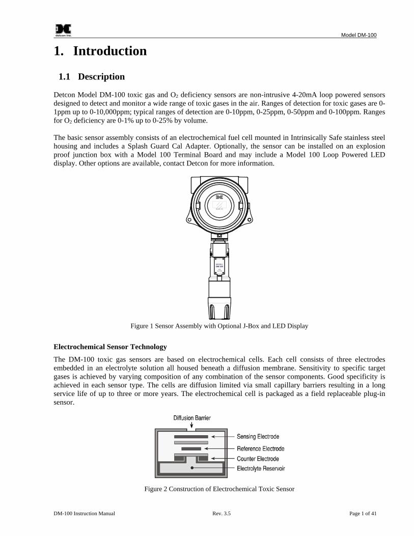
1.1 Description Detcon Model DM-100 toxic gas and O2 deficiency sensors are non-intrusive 4-20mA loop powered sensors designed to detect and monitor a wide range of toxic gases in the air. Ranges of detection for toxic gases are 0-1ppm up to 0-10,000ppm; typical ranges of detection are 0-10ppm, 0-25ppm, 0-50ppm and 0-100ppm. Ranges for O2 deficiency are 0-1% up to 0-25% by volume. The basic sensor assembly consists of an electrochemical fuel cell mounted in Intrinsically Safe stainless steel housing and includes a Splash Guard Cal Adapter. Optionally, the sensor can be installed on an explosion proof junction box with a Model 100 Terminal Board and may include a Model 100 Loop Powered LED display. Other options are available, contact Detcon for more information.
DETCON, INC.
H2S100 PPM
DM-100
Model 100
Figure 1 Sensor Assembly with Optional J-Box and LED Display
Electrochemical Sensor Technology
The DM-100 toxic gas sensors are based on electrochemical cells. Each cell consists of three electrodes embedded in an electrolyte solution all housed beneath a diffusion membrane. Sensitivity to specific target gases is achieved by varying composition of any combination of the sensor components. Good specificity is achieved in each sensor type. The cells are diffusion limited via small capillary barriers resulting in a long service life of up to three or more years. The electrochemical cell is packaged as a field replaceable plug-in sensor.
Figure 2 Construction of Electrochemical Toxic Sensor

Model DM-100
DM-100 Instruction Manual Rev. 3.5 Page 2 of 41
The DM-100 O2 deficiency sensor technology is a two electrode galvanic metal air battery type cell, which is housed as a field replaceable intelligent plug-in sensor. The cell is diffusion limited and functions as a direct current generator proportional to the amount of oxygen adsorption. The sensors are temperature compensated and show good accuracy and stability over the operating temperature range of -20° to 50°C (-4° to +122° F). The sensor is warranted for two years and has an expected service life of up to 2.5 years in ambient air at 20.9% oxygen.
Figure 3 Construction of Galvanic Cell
1.2 Modular Mechanical Design The Model DM-100 Sensor Assembly is completely modular and is made up of four parts (Figure 4):
1. DM-100 Intelligent Transmitter Module (ITM) 2. Intelligent Plug-in Sensor (varies by gas type and range) 3. 100 Series Bottom Housing Assembly (H2S assemblies use 100 Series Bottom Housing Assembly
with Integral Filter) 4. Splash Guard.
O-Ring
100 Series BottomHousing Assembly
Plug-inReplaceableSensor
InterconnectWires
Housing BottomLocking Screw
Intelligent Transmitter Module (ITM)Micro-processor controlled circuitencapsulated in an Explosion proofhousing.
MagneticProgramming
Switches
Splash Guard
DETC
ON
, INC
.
H2S
100 PPM
DM
-100
34" NPT Locking Nut
Figure 4 Sensor Assembly Breakaway
NOTE All metal components are constructed from electro polished 316 Stainless Steel in order to maximize corrosion resistance in harsh environments.
Model DM-100
DM-100 Instruction Manual Rev. 3.5 Page 3 of 41
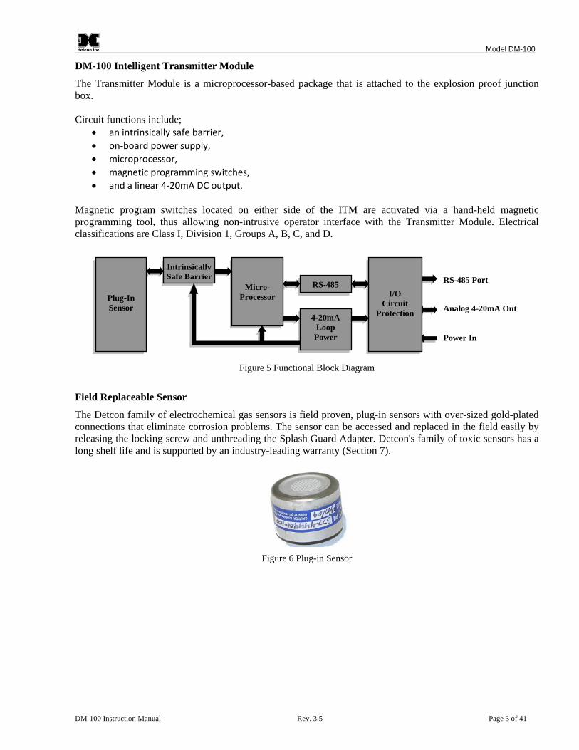
DM-100 Intelligent Transmitter Module
The Transmitter Module is a microprocessor-based package that is attached to the explosion proof junction box. Circuit functions include;
• an intrinsically safe barrier, • on-board power supply, • microprocessor, • magnetic programming switches, • and a linear 4-20mA DC output.
Magnetic program switches located on either side of the ITM are activated via a hand-held magnetic programming tool, thus allowing non-intrusive operator interface with the Transmitter Module. Electrical classifications are Class I, Division 1, Groups A, B, C, and D.
Figure 5 Functional Block Diagram Field Replaceable Sensor
The Detcon family of electrochemical gas sensors is field proven, plug-in sensors with over-sized gold-plated connections that eliminate corrosion problems. The sensor can be accessed and replaced in the field easily by releasing the locking screw and unthreading the Splash Guard Adapter. Detconꞌs family of toxic sensors has a long shelf life and is supported by an industry-leading warranty (Section 7).
Figure 6 Plug-in Sensor
I/O
Circuit Protection
RS-485 Port
Analog 4-20mA Out
Power In
RS-485
4-20mA Loop
Power
Micro-Processor
Intrinsically Safe Barrier
Plug-In Sensor

Model DM-100
DM-100 Instruction Manual Rev. 3.5 Page 4 of 41
1.3 Model 100 Standard Terminal Board (Optional) If the sensor is ordered with an explosion proof condulet/junction box, the sensor will come with the Model 100 Standard Terminal Board mounted in the J-Box (Figure 7). This terminal board affords the user easy plug-in connectors for use in wiring the unit during installation, and convenient test points for measuring the milliamp (mA) output.
RE
DG
RE
EN
BLU
EW
HIT
E
V+mA
Customer Wiring
Sensor Wiring Figure 7 DM Standard Terminal Board
The standard terminal board provides an easy Digital Volt Meter (DVM) connection for reading the mA output from the sensor. Two test points (TP1 and TP2) provide a connection across a 10Ω resistor that develops a 10mV voltage drop per 1mA output. Thus a reading of 40mV on a DVM equals 4mA of current. This is an alternative method to reading the mA output of the sensor for assemblies that do not include the DM-100 Series Display option. Refer to Section 2.6, Field Wiring for more information about the setup of the DM-100 Terminal Board.
1.4 DM-100 Display Terminal Board (Optional) If the unit is ordered with the optional display or a battery pack (wireless configurations) the unit comes with the DM-100 Display Terminal Board mounted in the J-Box (Figure 8).
J6
J7
J4
J1
J5
J8
L9
J2
AIN
1
W/B
K
W/B
N
W/B
U
W/G
N
W/V
WIRELESS
AIN
2
MA
GN
D
PWR
POWER IN( SOLAR)
WIRELESSPROGRAM
B A
GN
D
24V
MODBUS OUT( WIRELESS)
24V
GN
D A B
MODBUS IN
24V
GN
D A B
SENSOR
PWR
GN
D
SCL
SDA
SP1
SP2
DISPLAY
JP1
SW2
SW1
TERMPROGRAM
POWERmA
RED
BLAC
KBL
UE
WH
ITE
Customer Wiring
Figure 8 Model 100 Display Terminal Board

Model DM-100
DM-100 Instruction Manual Rev. 3.5 Page 5 of 41
This terminal board includes connectors for the following:
Table 1 Terminal Board Connectors
Terminal Connector Purpose J1 4-Pin Connector Modbus Out (Wireless Transceiver Option) J2 6-Pin Header Wireless Transceiver Programming Header J3 6-Beau Connector Battery operation or display interface dependent on sensor configuration J4 4-Pin Connector Modbus In J5 6-Pin Connector Display interface with battery/wireless configurations J6 4-Pin Connector Sensor connections J7 4-Pin Connector Auxiliary power in and mA out J8 6-Pin Connector Wireless Transceiver J9 5-Pin Header Terminal Board Programming
The Model 100 Display Terminal Board does not provide test points for measuring the milliamp (mA) output. The mA output is available at J7.
NOTE Install JP1 jumper on pins 1 and 2 if a battery pack is used. Install JP1 on pins 2 and 3 if battery is not used.
1.5 DM-100 Series Display (Optional) The DM-100 Series Display is a 4-digit LED display that provides a direct display of the sensor readings. In units that are ordered with the optional display, the display is mounted directly onto the J3 Beau connector of the Display Terminal Board so the display can be easily seen through the J-box window. The display automatically identifies the ITM, the sensor type, and range. This factory installed option must be ordered with the sensor assembly.
Figure 9 Model 100 Series Display
1.6 Wireless Transceiver and Battery Pack (Optional) The DM-100 has the option to operate on a wireless network with the addition of a wireless transceiver and battery pack. These options allow the sensor to be remotely mounted without the need for cables. These options are factory installed. Contact Detcon for more information on these options.

Model DM-100
DM-100 Instruction Manual Rev. 3.5 Page 6 of 41
2. Installation
2.1 Hazardous Locations Installation Guidelines for Safe Use
1. Install the sensor only in areas with classifications matching the approval label. Follow all warnings listed on the label.
Figure 10 Approval Label
2. For intrinsically safe Ex ia installations, follow the intrinsically safe installation guidelines shown in
control drawing #3993, Section 8.5.
3. For non-intrinsically safe Ex mb [ib] installations, ensure that the sensor is properly threaded into a suitable explosion-proof rated junction box with a downward pointing female 3/4" NPT threaded connection. The sensor should be threaded at least 5 full turns until tight, with the locking screw facing forward. Avoid use of Teflon Tape, or any type of non-conductive pipe thread coating on the NPT threaded connection.
4. A good ground connection should be verified between the sensor’s metal enclosure and the junction
box. If a good ground connection is not made, the sensor can be grounded to the junction box using the sensor’s external ground lug. Verify a good ground connection between the junction box and earth ground.
5. Proper precautions should be taken during installation and maintenance to avoid the build-up of static
charge on the plastic components of the sensor (Splash Guard and Splash Guard adapter).
6. All input circuits of the DM-100 must be connected to current limiting devices (e.g. Fuses of 1500 amp breaking capacity) to ensure that the maximum input current does not exceed 62mA.
7. Do not substitute components. Substitution of components may impair the intrinsic safety rating.
8. Do not operate the sensor outside of the stated operating temperature limits.
9. Do not operate the sensor outside the stated operating limits for voltage supply. 10. These sensors meet ATEX standards EN60079-0, EN60079-18 and EN60079-11.
11. These sensors have a maximum safe location voltage of Um=60V.
12. These sensors pass dielectric strength of 500VRMS between circuit and enclosure for a minimum of 1
minute at a maximum test current of 5mA.

Model DM-100
DM-100 Instruction Manual Rev. 3.5 Page 7 of 41
13. The DM-100 may be used as an oxygen deficiency sensor; the DM-100 must not be used for detecting oxygen concentrations expected to be greater than 21%.
14. The DM-100 must only use gas sensor cell models 371-xxxxxx-xxx (Table 5, Section 8.1). No other
gas sensor cells shall be used.
2.2 Sensor Placement Sensor location is critical to the overall safe performance of the product. Five factors play an important role in selection of sensor locations:
1. Density of the gas to be detected 2. Most probable leak sources within the industrial process 3. Ventilation or prevailing wind conditions 4. Personnel exposure 5. Maintenance access
Density
Placement of sensors relative to the density of the target gas is such that sensors for the detection of heavier than air gases should be located within 4 feet of grade as these heavy gases will tend to settle in low lying areas. For gases lighter than air, sensor placement should be 4 to 8 feet above grade in open areas or in pitched areas of enclosed spaces. Leak Sources
The most probable leak sources within an industrial process include flanges, valves, and tubing connections of the sealed type where seals may either fail or wear. Other leak sources are best determined by facility engineers with experience in similar processes. Ventilation
Normal ventilation or prevailing wind conditions can dictate efficient location of gas sensors in a manner where the migration of gas clouds is quickly detected. Personnel Exposure
The undetected migration of gas clouds should not be allowed to approach concentrated personnel areas such as control rooms, maintenance or warehouse buildings. A more general and applicable thought toward selecting sensor location is combining leak source and perimeter protection in the best possible configuration. Maintenance Access
Consideration should be given to providing easy access for maintenance personnel and the consequences of close proximity to contaminants that may foul the sensor prematurely.
NOTE In all installations the gas sensor should point straight down (Figure 12). Improper sensor orientation may result in false readings and permanent sensor damage.
Additional Placement Considerations
The sensor should not be positioned where it may be sprayed or coated with surface contaminating substances. Painting sensor assemblies is prohibited.

Model DM-100
DM-100 Instruction Manual Rev. 3.5 Page 8 of 41
Although the sensor is designed to be RFI resistant, it should not be mounted in close proximity to high-powered radio transmitters or similar RFI generating equipment. When possible mount in an area void of high wind, accumulating dust, rain, or splashing from hose spray, direct steam releases, and continuous vibration. If the sensor cannot be mounted away from these conditions then ensure the Detcon Harsh Location Dust Guard accessory is used. Do not mount in locations where temperatures will exceed the operating temperature limits of the sensor. Where direct sunlight leads to exceeding the high temperature-operating limit, use a sunshade to help reduce temperature.
2.3 Sensor Contaminants and Interference Electrochemical toxic gas may be adversely affected by exposure to other airborne gases. Depending on the cross-sensitivity relationship, there may be a positive or negative impact on the reading. The most commonly present gases that potentially cause interference problems are listed in Table 4, Interfering Gases and Table 5, Cross Interference Table (Section 8.3, Interference Table). The presence of cross-interference gases in an area does not preclude the use of this sensor technology. The sensor could experience a false high or false low reading should exposure occur. Cross-Interference Data Table
The gases typically found in industrial environments that may cause a cross-interference response on Detcon toxic gas sensors are listed in Table 5 (Section 8.3, Interference Table). Review Table 5 for the correct gas and then scan across the list for possible interference gases. Determine the magnitude of cross-interference that may occur.
2.4 Sensor Mounting The DM-100 should be vertically oriented so that the sensor points straight downward. The explosion-proof enclosure or junction box is typically mounted on a wall or pole (Figure 11). Detcon provides a selection of standard junction boxes in both Aluminum and Stainless Steel.
NOTE If wall mounting without a mounting plate, make sure to use at least 0.5" spacers underneath the J-Box’s 1/4" mounting holes to move the wireless sensor assembly away from the wall and allow access clearance to the sensor assembly.
NOTE
Do not use Teflon Tape or any other type of Pipe Thread material on the 3/4" threads unless the sensor is mounted in a severe or harsh environment. Metal-on-metal contact must be maintained to provide a solid electrical ground path. If Teflon Tape is used the Sensor must be externally grounded using a ground strap.

Model DM-100
DM-100 Instruction Manual Rev. 3.5 Page 9 of 41
When mounting on a pole, secure the Junction Box to a suitable mounting plate and attach the mounting plate to the pole using U-Bolts. (Pole-Mounting brackets for Detcon Junction Box’s are available separately.)
8-32 tappedground point
4.35"
34 NPT Ports6.1"
5.5"
14" mounting holes
Wal
l (or
oth
erm
ount
ing
surfa
ce)
Splash Guard Adapter
Splash Guard2"
DETCON, INC.
H2S100 PPM
DM-100
ITM Assembly
13.75" Typ.9.625" Typ.
Use spacers to movesensor assembly away from wall at least 0.5".
Spa
cer
Figure 11 Typical DM-100 Sensor Assembly and Mounting Dimensions
2.5 Electrical Installation The Sensor Assembly should be installed in accordance with local electrical codes. The sensor assemblies are CSA/NRTL approved (US and Canada) for Class I, Division 1, Groups A, B, C, & D area classifications, and are ATEX Approved for Class I, Zone 1, Group IIC area classifications. Proper electrical installation of the gas sensor is critical for conformance to Electrical Codes and to avoid damage due to water leakage. Refer to Figure 8 and Figure 12 for proper electrical installation.
NOTE If a conduit run exits the secondary port, repeat the installation technique shown in Figure 12.
In Figure 12, the drain allows H2O condensation inside the conduit run to safely drain away from the sensor assembly. The electrical seal fitting is required to meet the National Electrical Code per NEC Article 500-3d (or Canadian Electrical Code Handbook, Part 1, Section 18-154). Requirements for locations of electrical seals are covered under NEC Article 501-5. Electrical seals act as a secondary seal to prevent water from entering the wiring terminal enclosure. However, they are not designed to provide an absolute watertight seal, especially when used in the vertical orientation.

Model DM-100
DM-100 Instruction Manual Rev. 3.5 Page 10 of 41
NOTE
For products utilizing the aluminum junction box option, the conduit seal shall be placed at the entry to the junction box (see Figure 12 as an example). For products utilizing the stainless steel junction box option, the conduit seal shall be placed within 18" of the enclosure. Crouse Hinds type EYS2, EYD2 or equivalent are suitable for this purpose.
NOTE The Detcon Warranty does not cover water damage resulting from water leaking into the enclosure.
Drain
Conduit
"T" EYS Seal Fitting
DETCON, INC.
H2S100 PPM
DM-100
Model 100
Figure 12 Typical Installation
NOTE Any unused ports should be blocked with suitable 3/4" male NPT plugs. Detcon supplies one 3/4" NPT male plug with each J-box enclosure. If connections are other than 3/4" NPT, use an appropriate male plug of like construction material.
2.6 Field Wiring Detcon Model DM-100 sensor assemblies require two conductor connections between power supplies and host electronic controller’s 4-20mA input. Wiring designations are PWR and mA (sensor signal).
NOTE Shielded cable is required for installations where cable trays or conduit runs include high voltage lines or other possible sources of induced interference. Separate conduit runs are highly recommended in these cases.
NOTE The supply of power should be from an isolated source with over-current protection.

Model DM-100
DM-100 Instruction Manual Rev. 3.5 Page 11 of 41
Terminal Connections – with Junction Box Option
CAUTION Do not apply System power to the sensor until all wiring is properly terminated. Refer to Section 2.7, Initial Start Up.
1. Remove the junction box cover. 2. If the sensor has the Display option installed, unplug the display from the terminal board by pulling the
display out of the junction box. The display option plugs directly into the terminal board’s Beau Connector.
3. Observing correct polarity, terminate the 2-conductor power and 4-20mA field wiring (+ and mA) at the
terminal board connector J1 (4-20mA Out) on the Standard Terminal Board shown in Figure 7, or J7 (PWR and MA) on the Display Terminal Board shown in Figure 8.
4. Trim and cap all exposed wire leads if they are not permanently landed in the terminal board. 5. The sensor should be connected to J2, labeled SENSOR on the Standard Terminal Board, and J6, labeled
SENSOR, on the Display Terminal Board. On the Standard Terminal Board, the wiring from the sensor should match the silkscreen on the terminal board: R–Red, BK–Black, GN-Green, BU–Blue, and W–White. On the Display Terminal Board the wiring should be: Red-PWR, Black-GND, White–A, Blue–B (Green is not connected).
6. On the Display Terminal Board other connectors are provided for factory installed options. The options
ordered will dictate if, and what connectors are used. The display option is plugged into the Beau connector (J3) for a DM-100 with just the display option added. Other options are covered in the associated manual for those options.
7. If a display was removed in Step 2, re-install the display by plugging it back into the terminal board. 8. Replace the junction box cover after initial startup.
NOTE A 6-32 or 8-32 threaded exterior ground point is provided on most junction boxes for an external ground. If the Sensor Assembly is not mechanically grounded, an external ground strap must be used to ensure that the sensor is electrically grounded.
2.6.1 DM-100 Display Terminal Board Settings
The Model 100 Display Terminal Board contains a jumper that must be configured properly for the board to operate correctly. The jumper is normally configured at the factory and should not be changed. Misplacement of the jumper may cause the sensor to become inoperative.
Table 2 Model 100 Terminal Board Jumper JP1 1-2 – Battery installed 2-3 – Display only
2.7 Initial Start Up
2.7.1 Toxic Gas Sensors Upon completion of all mechanical mounting and termination of all field wiring, apply system power in the range of 11-26VDC (24VDC typical) and observe the following normal conditions:

Model DM-100
DM-100 Instruction Manual Rev. 3.5 Page 12 of 41
1. If the Loop Powered Display option is installed, the display should read 0.0 upon power up. If a Loop
Powered Display is not installed on the sensor, set a DVM to measure millivolts, and connect it across TP1 and TP2 on the terminal board. The DVM will read the voltage drop across a 10Ω resistor. The resistor develops a 10mV voltage drop per 1mA of current. Thus a reading of 40mV on a DVM equals 4mA of current.
2. A temporary upscale reading may occur as the sensor stabilizes. This upscale reading will decrease to
"0" ppm (40mV on the DVM) within 1 to 2 minutes of power-up, assuming there is no gas in the area of the sensor.
NOTE The 4-20mA signal is held constant at 4mA for the first two minutes after power up.
3. Sensors cells that use a bias voltage require a longer time to stabilize. This can vary between 1 and 24
hours depending on the sensor type and range. Biased sensors include NH3, NO, HCl, and VOC gases (ethylene oxide, ethylene, methanol, formaldehyde….etc).
Initial Operational Tests
After a warm up period of 1 hour (or when zero has stabilized), the sensor should be checked to verify sensitivity to the target gas. Material Requirements
• Detcon PN 613-120000-700 700 Series Splash Guard with integral Cal Port and Calibration Wind Guard (P/N 943-000000-000) -OR-
• Detcon PN 943-000006-132 Threaded Calibration Adapter - OR - • Detcon PN 943-01747-T05 Teflon Calibration Adapter for highly reactive gases • Detcon Span Gas; 50% of range target gas in balance N2 or Air at fixed flow rate between
200-500cc/min (500cc/min is preferred) • DVM (if a loop powered display is not installed)
NOTE Calibration gas generators using perm tubes or electrochemical sources may be used in place of span gas cylinders.
NOTE The cover of the junction box will need to be removed if there is not a loop powered display. The area may need to be de-classified.
1. If the sensor has a loop power display installed, the display should read "0". If a DVM is used to
measure the 4-20mA output, set the DVM to measure millivolts and connect the leads across TP1 and TP2 on the terminal board. The DVM should read 40±2mV.
2. Attach the calibration adapter to the Splash Guard adapter or connect tubing to integral cal port. It is
recommended that the Wind Guard (PN 943-000000-000) in installed over the Splash Guard during calibration. Apply the test gas at a controlled flow rate of 200-500cc/min (500cc/min is the recommended flow). If the sensor has a loop power display attached the reading should increase to 50% of full range (if the range is 100, the display should read 50). Observe that the DVM increases to a level near that of the applied calibration gas value. Typically this would be 50% of full range, a reading of 120±2mV (12mA).
3. Remove test gas and observe that, if the sensor has a loop power display installed, the display
decreases to "0". If a DVM is used the DVM reading should decrease back to 40mV (4mA).
Model DM-100
DM-100 Instruction Manual Rev. 3.5 Page 13 of 41
4. If a calibration adapter was used during these tests, remove them from the unit, and re-install the Splash Guard. If the wind guard was used, remove the wind guard.
Initial operational tests are complete. DM-100 toxic gas sensors are factory calibrated prior to shipment, and should not require significant adjustment on start up. However, it is recommended that a complete calibration test and adjustment be performed 16 to 24 hours after power-up. Refer to zero and span calibration instructions in Section 3.3, Calibration.
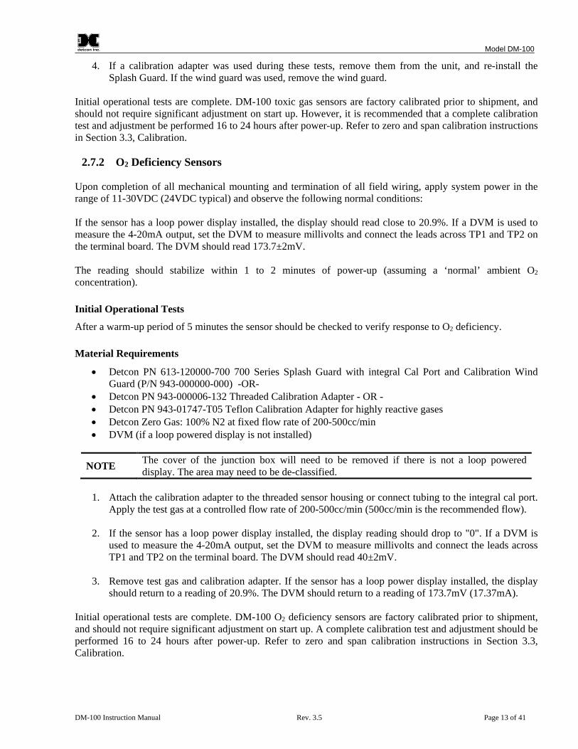
2.7.2 O2 Deficiency Sensors Upon completion of all mechanical mounting and termination of all field wiring, apply system power in the range of 11-30VDC (24VDC typical) and observe the following normal conditions: If the sensor has a loop power display installed, the display should read close to 20.9%. If a DVM is used to measure the 4-20mA output, set the DVM to measure millivolts and connect the leads across TP1 and TP2 on the terminal board. The DVM should read 173.7±2mV. The reading should stabilize within 1 to 2 minutes of power-up (assuming a ‘normal’ ambient O2 concentration). Initial Operational Tests
After a warm-up period of 5 minutes the sensor should be checked to verify response to O2 deficiency. Material Requirements
• Detcon PN 613-120000-700 700 Series Splash Guard with integral Cal Port and Calibration Wind Guard (P/N 943-000000-000) -OR-
• Detcon PN 943-000006-132 Threaded Calibration Adapter - OR - • Detcon PN 943-01747-T05 Teflon Calibration Adapter for highly reactive gases • Detcon Zero Gas: 100% N2 at fixed flow rate of 200-500cc/min • DVM (if a loop powered display is not installed)
NOTE The cover of the junction box will need to be removed if there is not a loop powered display. The area may need to be de-classified.
1. Attach the calibration adapter to the threaded sensor housing or connect tubing to the integral cal port.
Apply the test gas at a controlled flow rate of 200-500cc/min (500cc/min is the recommended flow).
2. If the sensor has a loop power display installed, the display reading should drop to "0". If a DVM is used to measure the 4-20mA output, set the DVM to measure millivolts and connect the leads across TP1 and TP2 on the terminal board. The DVM should read 40±2mV.
3. Remove test gas and calibration adapter. If the sensor has a loop power display installed, the display
should return to a reading of 20.9%. The DVM should return to a reading of 173.7mV (17.37mA). Initial operational tests are complete. DM-100 O2 deficiency sensors are factory calibrated prior to shipment, and should not require significant adjustment on start up. A complete calibration test and adjustment should be performed 16 to 24 hours after power-up. Refer to zero and span calibration instructions in Section 3.3, Calibration.
Model DM-100
DM-100 Instruction Manual Rev. 3.5 Page 14 of 41
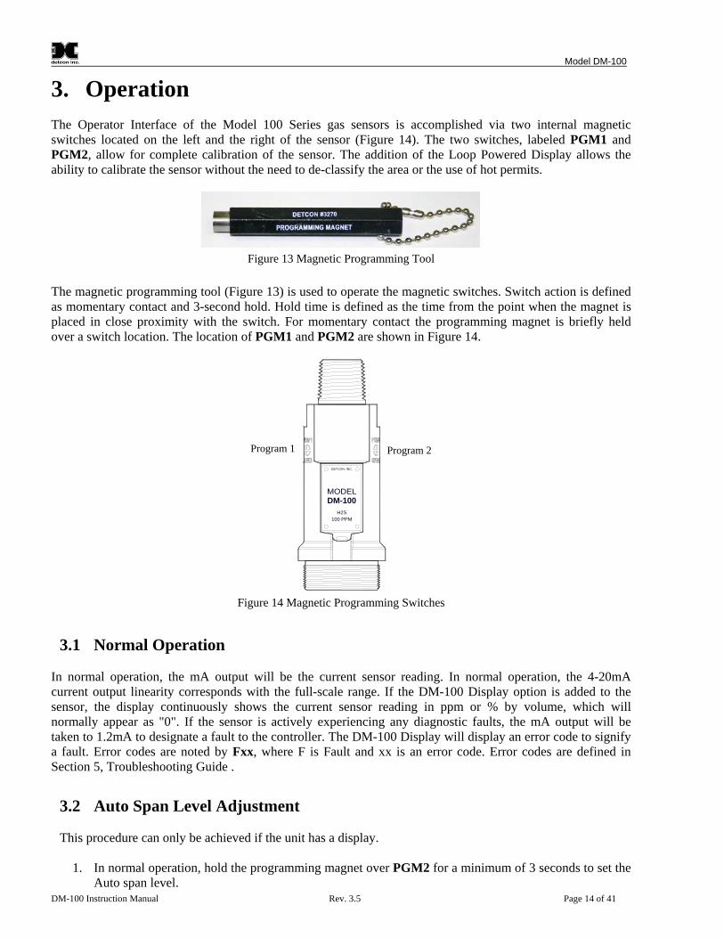
3. Operation The Operator Interface of the Model 100 Series gas sensors is accomplished via two internal magnetic switches located on the left and the right of the sensor (Figure 14). The two switches, labeled PGM1 and PGM2, allow for complete calibration of the sensor. The addition of the Loop Powered Display allows the ability to calibrate the sensor without the need to de-classify the area or the use of hot permits.
Figure 13 Magnetic Programming Tool
The magnetic programming tool (Figure 13) is used to operate the magnetic switches. Switch action is defined as momentary contact and 3-second hold. Hold time is defined as the time from the point when the magnet is placed in close proximity with the switch. For momentary contact the programming magnet is briefly held over a switch location. The location of PGM1 and PGM2 are shown in Figure 14.
DETCON, INC.
H2S100 PPM
DM-100
Program 1 Program 2
Figure 14 Magnetic Programming Switches
3.1 Normal Operation In normal operation, the mA output will be the current sensor reading. In normal operation, the 4-20mA current output linearity corresponds with the full-scale range. If the DM-100 Display option is added to the sensor, the display continuously shows the current sensor reading in ppm or % by volume, which will normally appear as "0". If the sensor is actively experiencing any diagnostic faults, the mA output will be taken to 1.2mA to designate a fault to the controller. The DM-100 Display will display an error code to signify a fault. Error codes are noted by Fxx, where F is Fault and xx is an error code. Error codes are defined in Section 5, Troubleshooting Guide .
3.2 Auto Span Level Adjustment This procedure can only be achieved if the unit has a display.
1. In normal operation, hold the programming magnet over PGM2 for a minimum of 3 seconds to set the Auto span level.

Model DM-100
DM-100 Instruction Manual Rev. 3.5 Page 15 of 41
2. SET AUTO SPAN will scroll across the display to indicate entry into the routine.
3. When adjustments can be made, the display will scroll ADJUST AUTO SPAN. Swipe PGM2 to adjust the AutoSpan Level up. Swipe PGM1 to adjust it down.
4. If no action is taken within 5 seconds, the display will scroll AUTO SPAN NOT SAVED to indicate
a value was not saved. The unit will then return to normal operation.
5. If changes are made, the display will reflect the adjustments.
6. A 2 second hold on PGM1 or PGM2 will save the level. The display will scroll AUTO SPAN SAVED to indicate that the value was saved and the unit will return to normal operation.
7. If no hold is placed on PGM1 or PGM2, the level will revert to the previous value. The display will
scroll AUTO SPAN NOT SAVED to indicate that the value was not saved and the unit will return to normal operation.
3.3 Calibration Zero and span calibration should be performed on a routine basis (quarterly minimum) to ensure reliable performance. If a sensor has been exposed to any de-sensitizing gases, or to very high over-range combustible gas levels, re-calibration should be considered. Unless otherwise specified, span adjustment is recommended at 50% of the full scale range.
3.3.1 Zero Calibration The zero calibration is used to zero the sensor. Zero calibration should be performed periodically or as required. Zero calibration should be considered after periods of over-range target gas exposure. Local ambient air can be used to zero calibrate a toxic gas sensor as long as it can be confirmed that it contains no target or interference gases. If this cannot be confirmed then a zero air or N2 cylinder should be used. Pure N2 must be used for zero calibration of the O2 deficiency sensors. Material Requirements:
• Detcon PN 327-000000-000 Programming Magnet • Detcon PN 613-120000-700 700 Series Splash Guard with integral Cal Port and Calibration Wind
Guard (P/N 943-000000-000) -OR- • Detcon PN 943-000006-132 Threaded Calibration Adapter - OR - • Detcon PN 943-01747-T05 Teflon Calibration Adapter for highly reactive gases • Detcon PN 942-001123-000 Zero Air cal gas (or use ambient air if no target gas is present). • Detcon PN 942-640023-100 Nitrogen 99.99% • DVM (if a loop powered display is not installed)
NOTE 1: The zero gas source may be zero air or N2 for toxic sensors, but must be pure N2 (99.99%) for O2 deficiency sensors.
NOTE 2: The Calibration Wind Guard must be used when the Splashguard Adapter with integral Cal Port is used. Failure to use the Calibration Wind Guard may result in an inaccurate AutoZero calibration.
NOTE 3: The cover of the junction box will need to be removed if there is not a loop powered display. The area may need to be de-classified.

Model DM-100
DM-100 Instruction Manual Rev. 3.5 Page 16 of 41
3.3.1.1 Display Not Installed
1. If a DM-100 Display is not installed on the sensor, set a DVM to measure millivolts, and connect it
across TP1 and TP2 on the terminal board. The DVM will read the voltage drop across a 10Ω resistor. The resistor develops a 10mV voltage drop per 1mA of current. Thus a reading of 40mV on a DVM equals 4mA of current.
2. For toxic sensors, if the ambient air is known to contain no target gas content, then it can be used for
zero calibration. If a zero gas cal cylinder is going to be used, attach the calibration adapter and set flow rate of 200-500cc/min (500cc/min is the recommended flow rate) and let the sensor purge for 1 to 2 minutes before zeroing the sensor. For O2 deficiency sensors, apply N2 at a set flow rate of 500cc/min for 3 to 5 minutes before zeroing the sensor.
NOTE: For O2 deficiency sensors N2 (99.99%) MUST be applied at a flow rate of 500cc/min for a time period of 3 to 5 minutes to successfully zero calibrate the sensor.
3. From Normal Operation, hold the programming magnet over PGM1 for 3 seconds. The reading will
dip momentarily to 2mA (20mV on the meter). The reading will then return to 4ma. (The ideal reading for zero is 4.03mA or 40.3mV.)
4. Observe the reading for a minute or so to ensure that the reading does not drift.
5. If zero gas was used, remove the gas from the sensor.
3.3.1.2 With Display
1. For toxic sensors, if the ambient air is known to contain no target gas content, then it can be used for zero calibration. If a zero gas cal cylinder is going to be used, attach the calibration adapter and set flow rate of 200-500cc/min (500cc/min is the recommended flow rate) and let the sensor purge for 1 to 2 minutes before zeroing the sensor. For O2 deficiency sensors, apply N2 at a set flow rate of 500cc/min for 3 to 5 minutes before zeroing the sensor.
NOTE: For O2 deficiency sensors N2 (99.99%) MUST be applied at a flow rate of 500cc/min for a time period of 3 to 5 minutes to successfully zero calibrate the sensor.
2. From Normal Operation, hold the programming magnet over PGM1 for 3 seconds. The display will
scroll 1-ZERO…2-SPAN for 10 seconds.
NOTE If no action is taken unit returns to normal operation after time expires, 10 seconds.
3. Hold PGM1 to start Auto Zero routine, ZERO IN PROGRESS… will scroll across the display. Output current from the sensor will drop to 3.5mA.
4. Observe the reading for a minute or so to ensure that the reading does not drift.
5. If zero gas was used, remove the gas from the sensor.

Model DM-100
DM-100 Instruction Manual Rev. 3.5 Page 17 of 41
3.3.2 Span Calibration Span Calibration is used to adjust the span of the sensor and should be performed periodically or as required. Span calibration should be considered after periods of over-range target gas exposure. Unless otherwise specified, span adjustment is recommended at 50% of range. Material Requirements:
• Detcon PN 327-000000-000 Programming Magnet • Detcon PN 613-120000-700 700 Series Splash Guard with integral Cal Port and Calibration Wind
Guard (P/N 943-000000-000) -OR- • Detcon PN 943-000006-132 Threaded Calibration Adapter - OR - • Detcon PN 943-01747-T05 Teflon Calibration Adapter for highly reactive gases • Detcon Span Gas (See Detcon for Ordering Information). Recommended span gas is 50% of range
with target gas. Other suitable span gas sources containing the target gas in air or N2 balance are acceptable.
• DVM (if a loop powered display is not installed)
NOTE 1; The cover of the junction box will need to be removed if there is not a loop powered display. The area may need to be de-classified.
NOTE 2:
A target gas concentration of 50% of range is strongly recommended. This should be applied at a controlled flow rate of 200 to 500cc/min, with 500cc/min being the recommended flow rate. Other concentrations can be used if they fall within allowable levels of 10% to 100% of range.
NOTE 3: The Calibration Wind Guard must be used when the Splashguard Adapter with integral Cal Port is used. Failure to use the Calibration Wind Guard may result in an inaccurate AutoZero calibration.
NOTE 4: Contact Detcon for ordering information on Span Gas cylinders.
NOTE 5: Ambient air should be used to calibrate O2 deficiency sensors as long as the oxygen concentration is confirmed to be 20.9%.
NOTE 6: Cross-calibration for span by use of other gases is not advised and should be confirmed by Detcon.
Span consists of applying the correct gas concentration at the correct flow rate, and adjusting the sensor for the proper output. The recommendation for span gas concentration is 50% of range. If a span gas containing the recommended concentration is not available, other concentrations may be used as long as they fall between 10% and 100% of range.
3.3.2.1 Display Not Installed
1. Set a DVM up to measure millivolts, and connect it across TP1 and TP2 on the terminal board. The DVM will read the voltage drop across a 10Ω resistor. The resistor develops a 10mV voltage drop per 1mA of current. Thus a reading of 40mV on the DVM equals 4mA of current.
2. Install the Calibration Wind Guard, or the appropriate calibration adapter.

Model DM-100
DM-100 Instruction Manual Rev. 3.5 Page 18 of 41
3. From normal operation, hold the programming magnet over PGM2 for at least 3 seconds. Apply the span calibration test gas for toxic gas sensors at a flow rate of 200-500cc/min (500cc/min is the recommended flow rate). The DVM reading will remain at 2mA or "0" for 2 minutes.
4. When the 2 minute wait is complete, the reading will increase to a level that corresponds to the level of gas the plug-in sensor is detecting. There is a 30 second period to decide if the reading needs to be adjusted. If the reading matches the level of gas applied continue to Step 7.
5. To adjust the reading, hold the programming magnet over PGM2. The reading will also start to
increase. Continue to hold the programming magnet over PGM2 to make the current increase, or hold the magnet over PGM1 to make the current decrease. Use PGM1 and PGM2 to adjust the output to match the target gas set-point. Assuming 50% of full range was applied, adjust the reading to 12mA (120mV on the DVM).
NOTE
12mA and 50% of full range are based on the use of a span gas concentration of 50%. If a different concentration of span gas is used, the mA reading will need to be calculated. I.E. if a 25% concentration span gas is used the reading would be 8mA. Use the magnetic tool to adjust the mA reading to the target set-point.
6. When the correct adjustment has been made, wait 15 seconds without holding the programming
magnet over either PGM1 or PGM2. The reading will momentarily decrease about 20% and then return to the target reading. This indicates that the span calibration point has been successfully saved. If a lack of proper signal level change is internally detected the sensor will immediately go into fault. The reading will go to 1.2ma (12mV). Only a successful re-calibration will clear this fault (Section 5, Troubleshooting Guide).
NOTE: For O2 deficiency sensors, N2 (99.99%) MUST be applied at a flow rate of 500cc/min for 2 to 3 minutes until the sensor reading clears below 2.5% volume O2. At this point the autospan cycle is complete. If not done properly a clearing fault will occur.
7. Remove the span gas and calibration adapter (or calibration wind guard), or for O2 deficiency sensors,
apply N2 at a set flow rate of 500cc/min. On the DVM, the reading will fall from the reported span level to 4mA (40mV). The sensor now allows 5 minutes for the reading to clear below 10% of full scale range (5.6mA). If the reading does not meet the clearing test criteria the sensor will go into fault. The reading will go to 1.2ma 12Mv). Only a successful re-calibration will clear this fault (Section 5, Troubleshooting Guide).
NOTE: For O2 deficiency sensors, N2 (99.99%) MUST be applied at a flow rate of 500cc/min for 2 to 3 minutes until the sensor reading clears below 2.5% volume O2. At this point the autospan cycle is complete. If not done properly a clearing fault will occur.
8. Span calibration is complete. If the Splash Guard was removed for calibration, re-install the Splash
Guard.
NOTE Any fault during the AutoSpan will cause the current output from the sensor to drop to 1.2mA (12mV).
3.3.2.2 Display Installed
1. Install calibration adapter or wind guard. 2. From Normal Operation, hold the programming magnet over PGM1 for 3 seconds. The display will
scroll 1-ZERO…2-SPAN.

Model DM-100
DM-100 Instruction Manual Rev. 3.5 Page 19 of 41
3. Hold PGM2 for three seconds and Auto span routine is executed and APPLY XXXXX UUU GGG is
scrolled across the display. Where XXXXX represent the auto span level, UUU represent the units (% or PPM), and GGG represent the gas type. Output current from the sensor will drop to 3.5mA.
4. Apply the span calibration test gas for toxic gas sensors at a flow rate of 200-500cc/min (500cc/min is
the recommended flow rate). As the sensor signal begins to increase the display will switch to XX reading as the ITM shows the sensor’s "as found" response to the span gas presented. If it fails to meet the minimum in-range signal change criteria within 21/2 minutes, the display will report a Range Fault fault code and the ITM will return to normal operation, aborting the AutoSpan sequence. The ITM will continue to report a Range Fault and will not clear the fault until a successful AutoSpan is completed.
5. Assuming acceptable sensor signal change, after 1 minute the reading will auto-adjust to the
programmed AutoSpan level. During the next 30 seconds, the AutoSpan sequence checks the sensor for acceptable reading stability. If the sensor fails the stability check, the reading is re-adjusted back to the AutoSpan level and the cycle repeats until the stability check is passed. Up to three additional 30-second stability check periods are allowed before the display scrolls a Stability Fault fault code and the sensor will return to normal operation, aborting the AutoSpan sequence. The sensor will continue to report a Stability Fault and will not clear the fault until a successful AutoSpan is completed.
NOTE: For O2 deficiency sensors, N2 (99.99%) MUST be applied at a flow rate of 500cc/min for 2 to 3 minutes until the sensor reading clears below 2.5% volume O2. At this point the autospan cycle is complete. If not done properly a clearing fault will occur.
6. Remove the span gas source and calibration adapter, or for O2 deficiency sensors, apply N2 at a set
flow rate of 500cc/min. The display will toggle between reporting a live reading and "REMOVE GAS" as it clears toward "0". When the reading clears below 10% of range, the display will scroll Span Complete and will revert to normal operation. If the sensor fails to clear to less than 10% in less than 5 minutes, a Clearing Fault fault code will be displayed and the sensor will return to normal operation, aborting the AutoSpan sequence. The sensor will continue to report a Clearing Fault and will not clear the fault until a successful AutoSpan is completed.
NOTE: For O2 deficiency sensors, N2 (99.99%) MUST be applied at a flow rate of 500cc/min for 2 to 3 minutes until the sensor reading clears below 2.5% volume O2. At this point the autospan cycle is complete. If not done properly a clearing fault will occur.
NOTE Any fault during the AutoSpan will cause the current output from the sensor to drop to 3.25mA.
3.4 Fault Diagnostic/Failsafe Feature If the ITM should incur a fault, the ITM will drop the mA output to 1.2mA (without display) or 3.25mA (with display). This can occur if the ITM;
• detects a problem with the sensor, • detects that there is no sensor cell connected, or • detects an internal ITM fault.
The ITM will hold the fault current output until the problem is resolved. If the DM-100 Display is installed, the display will show an error code. The error codes are defined in Section 5, Troubleshooting Guide.
Model DM-100
DM-100 Instruction Manual Rev. 3.5 Page 20 of 41
4. Service and Maintenance Calibration Frequency
In most applications, monthly to quarterly span calibration intervals will assure reliable detection. However, industrial environments differ. Upon initial installation and commissioning, close frequency tests should be performed, weekly to monthly. Test results should be recorded and reviewed to determine a suitable calibration interval. Visual Inspection
The Sensor should be inspected annually: • Inspect the sensor for signs of corrosion, pitting, and water damage. • Remove the Splash Guard and inspected it for blockage, broken, cracked, or missing pieces. • For H2S Sensor assemblies, inspect DM-100 Bottom Housing Assembly with integral filter (PN 602-
003552-100) for blockage of filter material. • Inspect inside of the Junction Box for signs of water accumulation, signs of corrosion. • Check wiring to ensure there are no loose or pinched wires and all connections are clean and tight.
Condensation Prevention Packet
A moisture condensation prevention packet (PN 960-202200-000) should be installed in every explosion proof Junction Box. The prevention packet will prevent the internal volume of the J-Box from condensing and accumulating moisture due to day-night humidity changes. This packet provides a critical function and should be replaced annually.
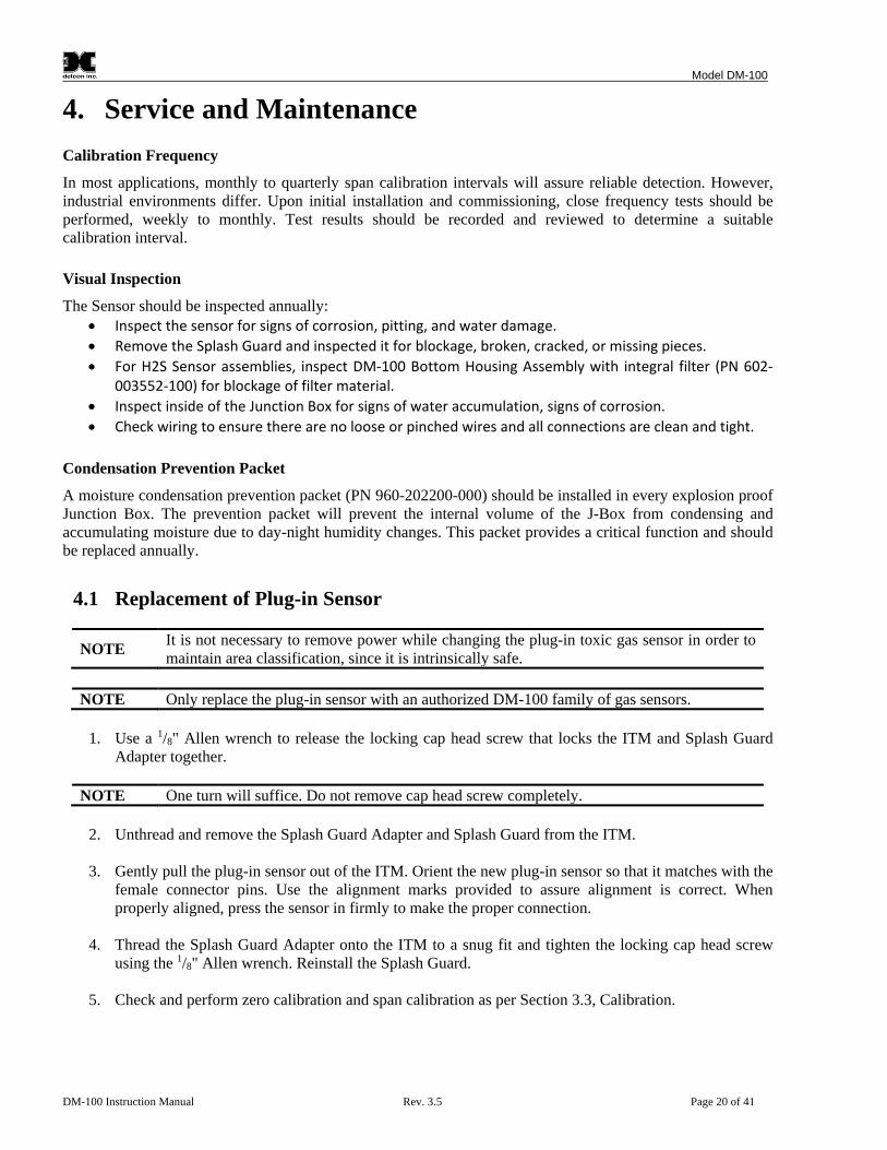
4.1 Replacement of Plug-in Sensor
NOTE It is not necessary to remove power while changing the plug-in toxic gas sensor in order to maintain area classification, since it is intrinsically safe.
NOTE Only replace the plug-in sensor with an authorized DM-100 family of gas sensors.
1. Use a 1/8" Allen wrench to release the locking cap head screw that locks the ITM and Splash Guard
Adapter together.
NOTE One turn will suffice. Do not remove cap head screw completely.
2. Unthread and remove the Splash Guard Adapter and Splash Guard from the ITM.
3. Gently pull the plug-in sensor out of the ITM. Orient the new plug-in sensor so that it matches with the female connector pins. Use the alignment marks provided to assure alignment is correct. When properly aligned, press the sensor in firmly to make the proper connection.
4. Thread the Splash Guard Adapter onto the ITM to a snug fit and tighten the locking cap head screw
using the 1/8" Allen wrench. Reinstall the Splash Guard.
5. Check and perform zero calibration and span calibration as per Section 3.3, Calibration.

Model DM-100
DM-100 Instruction Manual Rev. 3.5 Page 21 of 41
4.2 Replacement of ITM
1. Remove the power source to the sensor assembly. Disconnect all sensor wire connections at the Junction Box Terminal Board taking note of the wire connections.
NOTE It is necessary to remove power to the Junction box while changing the ITM in order to maintain area classification.
2. Use a wrench and the wrench flats provided at the top section of the ITM and unthread the ITM until it
can be removed.
3. Use a 1/8" Allen wrench to release the locking cap head screw that locks the ITM and Splash Guard Adapter together (One turn will suffice - Do not remove setscrew completely).
4. Unthread and remove the Splash Guard Adapter and Splash Guard from the ITM. These will be re-
used with the new ITM.
5. Gently remove the plug-in toxic gas sensor from the old ITM and install it in the new ITM. Orient the plug-in sensors so that it matches the female connector pins on the new ITM and press the sensor in firmly to make proper connection.
6. Thread the Splash Guard Adapter onto the new ITM until snug, tighten the locking cap head screw and
reinstall Splash Guard.
7. Feed the sensor assembly wires through the 3/4" female NPT mounting hole and thread the assembly into the J-box until tight and the ITM faces toward the front access point. Use the locking nut to secure the ITM in this position. Connect the sensor assembly wires to the terminal board inside the Junction Box (Section 2.6).
8. Check and/or perform Zero Calibration and Span Calibration (Section 3.3, Calibration).
4.3 Replacement of the Model 100 Terminal Board
1. Remove the power source to the sensor assembly.
NOTE It is necessary to remove power to the Junction Box while changing the Model 100 Terminal Board in order to maintain area classification.
2. Remove the junction box cover and remove the Loop Powered Display, if one is installed.
3. Remove the power connector on the terminal board.
4. Unplug all other connectors from the terminal board, noting where they are plugged into.
5. Remove the four 6-32 screws holding the terminal board to the base of the junction box and remove
the terminal board.
6. Install the new terminal board using the four 6-32 screws removed in Step 5.
7. If the unit has the DM-100 Display Terminal Board, ensure that the jumper on the terminal board is set properly (Section 2.6.1, DM-100 Display Terminal Board Settings).
8. Re-connect the sensor connector to the terminal board and all other connections removed in Step 4.

Model DM-100
DM-100 Instruction Manual Rev. 3.5 Page 22 of 41
9. Reconnect the power connector to the terminal board.
10. Re-install the DM-100 Display, if one was installed.
11. Reinstall the junction box cover, and restore power to the sensor.
12. Check operation of sensor assembly (Section 2.7, Initial Start Up).
Model DM-100
DM-100 Instruction Manual Rev. 3.5 Page 23 of 41
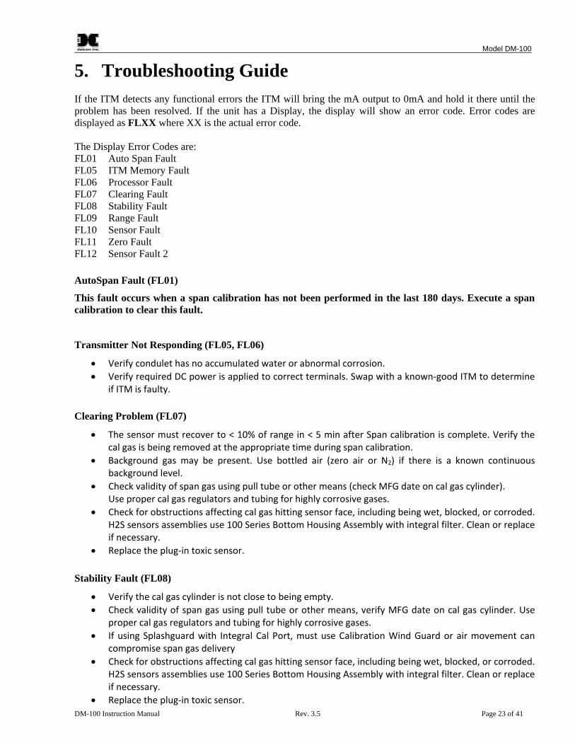
5. Troubleshooting Guide If the ITM detects any functional errors the ITM will bring the mA output to 0mA and hold it there until the problem has been resolved. If the unit has a Display, the display will show an error code. Error codes are displayed as FLXX where XX is the actual error code. The Display Error Codes are: FL01 Auto Span Fault FL05 ITM Memory Fault FL06 Processor Fault FL07 Clearing Fault FL08 Stability Fault FL09 Range Fault FL10 Sensor Fault FL11 Zero Fault FL12 Sensor Fault 2 AutoSpan Fault (FL01)
This fault occurs when a span calibration has not been performed in the last 180 days. Execute a span calibration to clear this fault.
Transmitter Not Responding (FL05, FL06)
• Verify condulet has no accumulated water or abnormal corrosion. • Verify required DC power is applied to correct terminals. Swap with a known-good ITM to determine
if ITM is faulty. Clearing Problem (FL07)
• The sensor must recover to < 10% of range in < 5 min after Span calibration is complete. Verify the cal gas is being removed at the appropriate time during span calibration.
• Background gas may be present. Use bottled air (zero air or N2) if there is a known continuous background level.
• Check validity of span gas using pull tube or other means (check MFG date on cal gas cylinder). Use proper cal gas regulators and tubing for highly corrosive gases.
• Check for obstructions affecting cal gas hitting sensor face, including being wet, blocked, or corroded. H2S sensors assemblies use 100 Series Bottom Housing Assembly with integral filter. Clean or replace if necessary.
• Replace the plug-in toxic sensor.
Stability Fault (FL08)
• Verify the cal gas cylinder is not close to being empty. • Check validity of span gas using pull tube or other means, verify MFG date on cal gas cylinder. Use
proper cal gas regulators and tubing for highly corrosive gases. • If using Splashguard with Integral Cal Port, must use Calibration Wind Guard or air movement can
compromise span gas delivery • Check for obstructions affecting cal gas hitting sensor face, including being wet, blocked, or corroded.
H2S sensors assemblies use 100 Series Bottom Housing Assembly with integral filter. Clean or replace if necessary.
• Replace the plug-in toxic sensor.

Model DM-100
DM-100 Instruction Manual Rev. 3.5 Page 24 of 41
Range Fault (FL09)
• Check validity of span gas with regulator and sample tubing in place using pull tube or other means (check MFG date on cal gas cylinder). Use proper cal gas regulators and tubing for highly corrosive gases (HF, HCI, Cl2, NH3, HBR, F2, etc.)
• Check for obstructions affecting cal gas hitting sensor face (including being wet, blocked, or corroded). H2S sensors assemblies use DM-100 Bottom Housing Assembly with integral filter. Clean or replace if necessary.
• If using Splashguard with Integral Cal Port, must use Calibration Wind Guard or air movement can compromise span gas delivery
• Verify there is no background cross interference gases. • Replace the plug-in toxic sensor.
Sensor Fault (FL10)
• Verify that the sensor cell is plugged into the ITM. • Swap cell with a known good cell to see if the fault clears. • Replace the sensor cell.
Zero Fault (FL11)
• The sensor zero baseline may have drifted lower. Perform Zero Calibration. Use Zero Air or N2 source (Section 3.3.1, Zero Calibration). Allow more time for zero stabilization if usuing a biased sensor type.
• Execute successful Span Calibration (Section 3.3.2, Span Calibration). Replace plug-in toxic sensor if error continues.
Unstable Output/Sudden Spiking
• Verify that the field wiring is properly shielded and grounded. • Verify that the power source is stable. • Contact Detcon to optimize shielding and grounding. • Add Detcon’s RFI Protection Circuit Accessory (PN 975-343002-007) if problem is proven RFI induced.
Nuisance Alarms
• Check condulet for accumulated water and abnormal corrosion on terminal board. If nuisance alarms are happening at night, suspect condensation in condulet.
• Add or replace Detcon’s Condensation Prevention Packet (PN 960-202200-000). • Investigate the presence of other target gases that are causing cross-interference signals. • Determine if cause is RFI induced.
Unreadable Display (If a DM-100 display is installed.)
• If due to excessive sunlight, install a sunshade to reduce glare. • Replace Display Assembly. • Replace DM-100 Display.
Blank or Incorrect Reading on Display (If a DM-100 display is installed.)
• ITM has an internal fault, problem with display. • Swap with a known-good ITM to determine if ITM is faulty.

Model DM-100
DM-100 Instruction Manual Rev. 3.5 Page 25 of 41
• Swap DM-100 Display Terminal Board with known good board. • Swap DM-100 Display with known good display.
5.1 Smart Display Error Codes These error codes are determined by the smart display and must be rectified before normal operation of the unit will continue. ER01
Firmware Incompatible: Sensor firmware version is not compatible with the display. ER02
Zero Range: The sensor has a range value of zero. ER03
Zero Auto Span: The sensor has an Auto Span value of zero.

Model DM-100
DM-100 Instruction Manual Rev. 3.5 Page 26 of 41
6. Customer Support and Service Policy Detcon Headquarters Shipping Address: 4055 Technology Forest Blvd, The Woodlands, Texas 77381 Mailing Address: P.O. Box 8067, The Woodlands Texas 77387-8067 Phone: 713-559-9200 Fax: 281.298.2868 • www.detcon.com • [email protected] • [email protected] All Technical Service and Repair activities should be handled by the Detcon Service Department via phone, fax or email (contact information given above). RMA numbers should be obtained from the Detcon Service Department prior to equipment being returned. For on-line technical service, have the model number, part number, and serial number of product(s) in question available. All Sales activities (including spare parts purchase) should be handled by the Detcon Sales Department via phone, fax or email (contact information given above). Warranty Notice
Detcon Inc. warrants the Model DM-100 gas sensor to be free from defects in workmanship of material under normal use and service for two years from the date of shipment on the transmitter electronics. See Warranty details in Section 7 DM-100 Sensor Warranty. Detcon Inc. will repair or replace without charge any such equipment found to be defective during the warranty period. Full determination of the nature of, and responsibility for, defective or damaged equipment will be made by Detcon Inc. personnel. Defective or damaged equipment must be shipped to the Detcon Inc. factory or representative from which the original shipment was made. In all cases, this warranty is limited to the cost of the equipment supplied by Detcon Inc. The customer will assume all liability for the misuse of this equipment by its employees or other contracted personnel. All warranties are contingent upon the proper use in the application for which the product was intended and does not cover products which have been modified or repaired without Detcon Inc. approval, or which have been subjected to neglect, accident, improper installation or application, or on which the original identification marks have been removed or altered. Except for the express warranty stated above, Detcon Inc. disclaims all warranties with regard to the products sold. Including all implied warranties of merchantability and fitness and the express warranties stated herein are in lieu of all obligations or liabilities on the part of Detcon Inc. for damages including, but not limited to, consequential damages arising out of, or in connection with, the performance of the product.

Model DM-100
DM-100 Instruction Manual Rev. 3.5 Page 27 of 41
7. DM-100 Sensor Warranty Plug-in Sensor Warranty Detcon Inc. warrants, under normal intended use, each new intelligent plug-in sensor per the period specified in the Warranty column of Table 3, Sensor Specific Data (Section 8.2, Sensor Specific Data) and under the conditions described as follows:
• The warranty period begins on the date of shipment to the original purchaser. • The sensor element is warranted to be free of defects in material and workmanship. • Should any sensor fail to perform in accordance with published specifications within the warranty
period, return the defective part to Detcon, Inc., 4055 Technology Forest Blvd, The Woodlands, Texas 77381, for necessary repairs or replacement.
Terms & Conditions • The original serial number must be legible on each sensor element base. • Shipping point is FOB the Detcon factory. • Net payment is due within 30 days of invoice. • Detcon, Inc. reserves the right to refund the original purchase price in lieu of sensor replacement. ITM Electronics Warranty Detcon Inc. warrants, under intended normal use, each new Model 100 ITM to be free from defects in material and workmanship for a period of two years from the date of shipment to the original purchaser. All warranties and service policies are FOB the Detcon facility located in The Woodlands, Texas. Terms & Conditions • The original serial number must be legible on each ITM. • Shipping point is FOB the Detcon factory. • Net payment is due within 30 days of invoice. • Detcon, Inc. reserves the right to refund the original purchase price in lieu of ITM replacement.

Model DM-100
DM-100 Instruction Manual Rev. 3.5 Page 28 of 41
8. Appendix
8.1 Specifications System Specifications
Sensor Type: Continuous diffusion/adsorption type 3-Electrode Electrochemical Sensor (2-Electrode for O2) Plug-in Replaceable Type
Sensor Life: 2 years typical Measuring Ranges: 0-1ppm up to 0-10,000ppm (Toxic Gases) 0-1% up to 0-25% volume (O2) Accuracy/ Repeatability: ±2% of full-range (other Toxic Gases) ±1% of full-range (O2) Response Time: T90 < 30 seconds typical (Table 3) Electrical Classification: CSA and US (NRTL)
Class I, Division 1, Groups A, B, C, D
ATEX Class I, Zone 1, Group IIC Ex d [ib] ib IIC T6
Approvals: CCSAUS, ATEX, CE Marking Warranty: Electronics – 2 years Sensor – (Table 3)
Environmental Specifications
Operating Temperature: -40°C to +50°C typical (Table 3) Storage Temperature: -35°C to +55°C typical Operating Humidity: 10-95% RH Continuous Duty (Table 3) 0-100% RH Short-Term Duration Only Operating Pressure: Ambient ± 10% Maximum Altitude 9000 Feet/3000 Meters Air Velocity: 0-5 meters/second
Electrical Specifications
Input Voltage: 10-28 VDC Power Consumption: Normal operation = 4 mA (0.1 watts @ 24VDC);
Maximum = 20 mA (0.5 watts @ 24VDC; 0.23 watts @ 11.5VDC) RFI/EMI Protection: Complies with EN61326

Model DM-100
DM-100 Instruction Manual Rev. 3.5 Page 29 of 41
Analog Output: Linear 4-20mA DC current 750 ohms maximum loop load @ 24VDC 1.2 mA All Fault Diagnostics (without display) 2mA Sensor in calibration (without display) 3.25mA All Fault Diagnostics (with display) 3.5mA Sensor in calibration (with display) 4-20 mA 0-100% full-scale 22 mA Over-range condition Cable Requirements: Power/Analog: 2-wire shielded cable
Maximum distance is 13,300 feet with 14 AWG
Mechanical Specifications
Length: 8.5 inches (215mm) DM-100 13.25 inches (337 mm) DM-100 w/ XP Display Width: 2.2 inches (55 mm) DM-100 6.0 inches (152 mm) DM-100 Weight: 2.5 lbs (1.2 Kg) DM-100 7.4 lbs (3.4 Kg) DM-100 w/ XP Display Mechanical Connection: 3/4" Male NPT threaded connection with locking nut (DM-100) Two ¾” female NPT Threaded connections (DM-100 w/ XP Display) Electrical Connection: four 18 gauge wire leads - 5.5" long (DM-100) Input terminations for two 18 gauge wires (DM-100 w/ XP Display)
8.2 Sensor Specific Data
Table 3 Sensor Specific Data
Gas GasName Part Number1 Response
Time (seconds)
SpanDrift Temperature Range °C
Humidity Range% Warranty
O2 Oxygen 371-343400-025 T95<30 <5%signal loss/year -20 to+50 15 to 90 2 years C2H3O Acetyldehyde 371-12EA00-100 T90<140 <5%signal loss/year -20 to+50 15 to 90 2 years C2H2 Acetylene 371-12EG00-100 T90<140 <5%signal loss/year -20 to+50 15 to 90 2 years C3H3N Acrylonitrile 371-12EM00-100 T90<140 <5%signal loss/year -20 to+50 15 to 90 2 years
NH3 Ammonia 371-171700-100 T90<90 <2%signal loss/month -20 to+50 15 to 90 2 years
AsH3 Arsine 371-191900-001 T90<60 <5%signal loss/month -20 to+40 20 to 95 1.5 years
Br2 Bromine 371-747500-005 T90<60 <2%signal loss/month -20 to+50 15 to 90 2 years
C4H6 Butadiene 371-12EB00-100 T90<140 <5%signal loss/year -20 to+50 15 to 90 2 years
CO Carbon Monoxide 371-444400-100 T90=30 <5%signal loss/year -40 to+50 15 to 90 3 years
Cl2 Chlorine 371-747400-010 T90<60 <2%signal loss/month -20 to+50 15 to 90 2 years
ClO2 (>10ppm) Chlorine Dioxide 371-777700-001 T90<60 <2%signal loss/month -20 to+50 15 to 90 2 years
1 The last three digits of the Part Number are the range of the sensor cell. I.E. "-100" is a 100ppm range.

Model DM-100
DM-100 Instruction Manual Rev. 3.5 Page 30 of 41
Gas GasName Part Number1 Response
Time (seconds)
SpanDrift Temperature Range °C
Humidity Range% Warranty
ClO2 (<=10ppm) Chlorine Dioxide 371-282800-050 T90<120 <1%signal
loss/month -20 to+40 10 to 95 2 years
B2H6 Diborane 371-192100-005 T90<60 <5%signal loss/month -20 to+40 20 to 95 1.5 years
C2H5OH Ethanol 371-12EO00-100 T90<140 <5%signal loss/year -20 to+50 15 to 90 2 years
C2H5SH Ethyl Mercaptan 371-24EZ00-100 T90<45 <2%signal loss/month -40 to+50 15 to 90 2 years
C2H4 Ethylene 371-12ED00-100 T90<140 <5%signal loss/year -20 to+50 15 to 90 2 years C2H4O Ethylene Oxide 371-12EJ00-100 T90<140 <5%signal loss/year -20 to+50 15 to 90 2 years F2 Fluorine 371-272700-001 T90<80 <5%signal loss/year -10 to+40 10 to 95 1.5 years CH2O Formaldehyde 371-12EP00-100 T90<140 <5%signal loss/year -20 to+50 15 to 90 2 years
GeH4 Germane 371-232500-002 T90<60 <1%signal loss/month -20 to+40 20 to 95 1.5 years
N2H4 Hydrazine 371-262600-001 T90<120 <5%signal loss/month -10 to+40 10 to 95 1 year
H2 (ppm) Hydrogen 371-848400-100 T90=30 <2%signal loss/month -20 to+50 15 to 90 2 years
H2 (LEL)* Hydrogen 371-050500-04P T90<60 <2%signal loss/month -40 to+40 5 to 95 2 years
HBr Hydrogen Bromide 371-090800-030 T90<70 <3%signal
loss/month -20 to+40 10 to 95 1.5 years
HCl Hydrogen Chloride 371-090900-030 T90<70 <2%signal
loss/month -20 to+40 10 to 95 1.5 years
HCN Hydrogen Cyanide 371-131300-030 T90<40 <5%signal
loss/month -40 to+40 5 to 95 2 years
HF Hydrogen Fluoride 371-333300-010 T90<90 <10%signal
loss/month -20 to+35 10 to 80 1.5 years
H2S Hydrogen Sulfide 371-242400-100 T80<30 <2%signal loss/month -40 to+50 15 to 90 2 years
CH3OH Methanol 371-12EE00-100 T90<140 <5%signal loss/year -20 to+50 15 to 90 2 years
CH3SH Methyl Mercaptan 371-24EK00-100 T90<45 <2%signal
loss/month -40 to+50 15 to 90 2 years
NO Nitric Oxide 371-949400-100 T90=10 <2%signal loss/month -20 to+50 15 to 90 3 years
NO2 Nitrogen Dioxide 371-646400-010 T90<40 <2%signal loss/month -20 to+50 15 to 90 2 years
O3 Ozone 371-999900-001 T90<120 <1%signal loss/month -10 to+40 10 to 95 2 years
COCl2 Phosgene 371-414100-001 T90<120 <1%signal loss/month -20 to+40 10 to 95 1.5 years
PH3 Phosphine 371-192000-005 T90<30 <1%signal loss/month -20 to+40 20 to 95 1.5 years
SiH4 Silane 371-232300-050 T90<60 <1%signal loss/month -20 to+40 20 to 95 1.5 years
SO2 SulfurDioxide 371-555500-020 T90=20 <2%signal loss/month -20 to+50 15 to 90 2 years
C4H6O2 Vinyl Acetate 371-12EF00-100 T90<140 <5%signal loss/year -20 to+50 15 to 90 2 years C2H3Cl Vinyl Chloride 371-12EL00-100 T90<140 <5%signal loss/year -20 to+50 15 to 90 2 years
Model DM-100
DM-100 Instruction Manual Rev. 3.5 Page 31 of 41
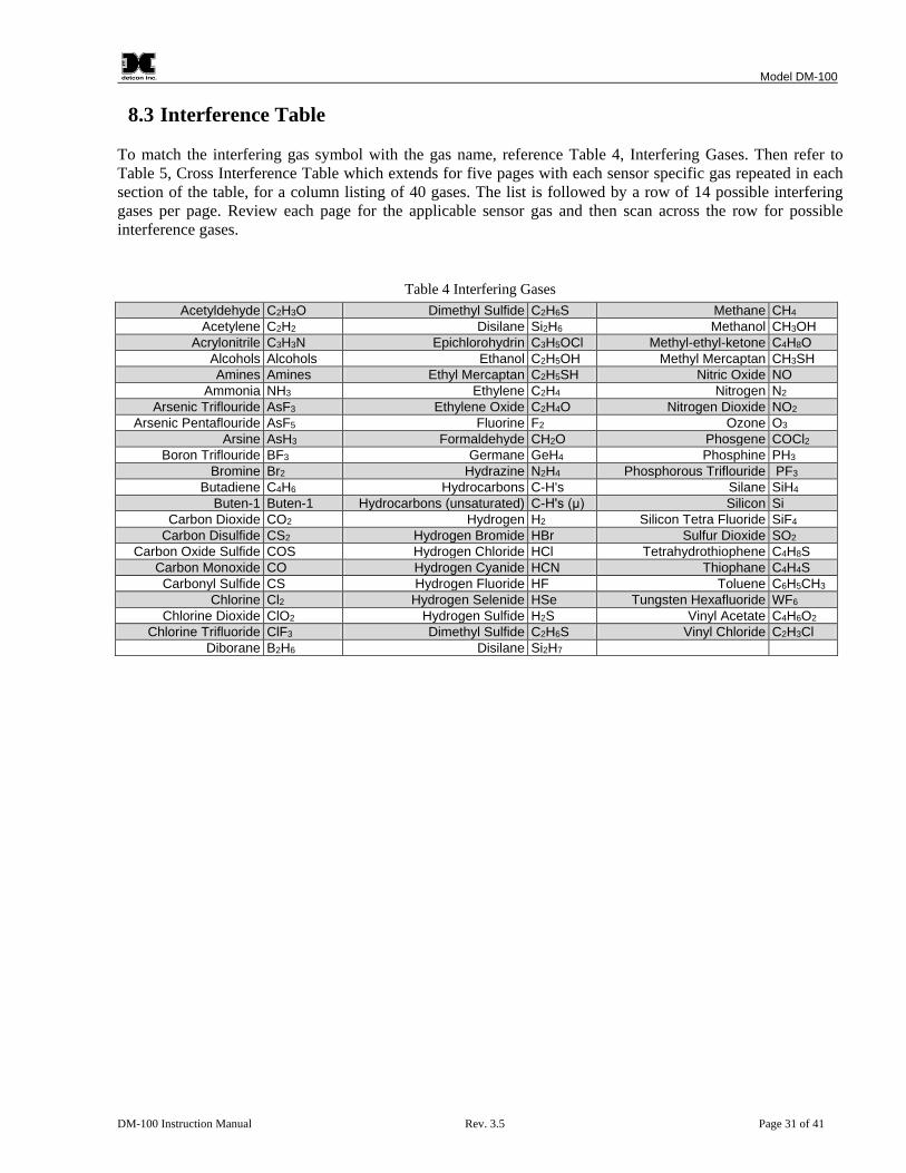
8.3 Interference Table To match the interfering gas symbol with the gas name, reference Table 4, Interfering Gases. Then refer to Table 5, Cross Interference Table which extends for five pages with each sensor specific gas repeated in each section of the table, for a column listing of 40 gases. The list is followed by a row of 14 possible interfering gases per page. Review each page for the applicable sensor gas and then scan across the row for possible interference gases.
Table 4 Interfering Gases Acetyldehyde C2H3O Dimethyl Sulfide C2H6S Methane CH4
Acetylene C2H2 Disilane Si2H6 Methanol CH3OH Acrylonitrile C3H3N Epichlorohydrin C3H5OCl Methyl-ethyl-ketone C4H8O
Alcohols Alcohols Ethanol C2H5OH Methyl Mercaptan CH3SH Amines Amines Ethyl Mercaptan C2H5SH Nitric Oxide NO
Ammonia NH3 Ethylene C2H4 Nitrogen N2 Arsenic Triflouride AsF3 Ethylene Oxide C2H4O Nitrogen Dioxide NO2
Arsenic Pentaflouride AsF5 Fluorine F2 Ozone O3 Arsine AsH3 Formaldehyde CH2O Phosgene COCl2
Boron Triflouride BF3 Germane GeH4 Phosphine PH3 Bromine Br2 Hydrazine N2H4 Phosphorous Triflouride PF3
Butadiene C4H6 Hydrocarbons C-H's Silane SiH4 Buten-1 Buten-1 Hydrocarbons (unsaturated) C-H's (μ) Silicon Si
Carbon Dioxide CO2 Hydrogen H2 Silicon Tetra Fluoride SiF4 Carbon Disulfide CS2 Hydrogen Bromide HBr Sulfur Dioxide SO2
Carbon Oxide Sulfide COS Hydrogen Chloride HCl Tetrahydrothiophene C4H8S Carbon Monoxide CO Hydrogen Cyanide HCN Thiophane C4H4S Carbonyl Sulfide CS Hydrogen Fluoride HF Toluene C6H5CH3
Chlorine Cl2 Hydrogen Selenide HSe Tungsten Hexafluoride WF6 Chlorine Dioxide ClO2 Hydrogen Sulfide H2S Vinyl Acetate C4H6O2
Chlorine Trifluoride ClF3 Dimethyl Sulfide C2H6S Vinyl Chloride C2H3Cl Diborane B2H6 Disilane Si2H7

Model DM-100
DM-100 Instruction Manual Rev. 3.5 Page 32 of 41
Table 5 Cross Interference Table
Gas C2H30 C2H2 C3H3N Alcohols Amines NH3 AsF3 AsF5 AsH3 BF3 Br2 C4H6 Buten-1 C2H3O n/a 40=340 40=75 n/d n/d n/d n/d n/d n/d n/d n/d 40=170 n/d C2H2 340=40 n/a 340=75 n/d n/d n/d n/d n/d n/d n/d n/d 340=170 n/d C3H3N 75=40 75=340 n/a n/d n/d n/d n/d n/d n/d n/d n/d 75=170 n/d NH3 n/d n/d n/d n/d n/d n/d n/d n/d n/d n/d n/d n/d n/d AsH3 n/d n/d n/d n/d n/d 100=0.01 n/d n/d n/a n/d n/d n/d n/d Br2 n/d n/d n/d n/d n/d n/d n/d n/d n/d n/d n/a n/d n/d C4H6 170=40 170=340 170=75 n/d n/d n/d n/d n/d n/d n/d n/d n/a n/d CS2 140=40 140=340 140=75 n/d n/d n/d n/d n/d n/d n/d n/d 140=170 n/d CO n/d n/d n/d n/d n/d n/d n/d n/d n/d n/d n/d n/d n/d Cl2 n/d n/d n/d n/d n/d n/d n/d n/d n/d n/d 1=0.55 n/d n/d ClO2 (>10ppm) n/d n/d n/d n/d n/d n/d n/d n/d n/d n/d 1=0.18 n/d n/d ClO2 (=10ppm) n/d n/d n/d n/d n/d n/d n/d n/d n/d n/d n/d n/d n/d B2H6 n/d n/d n/d n/d n/d 100=0.013 n/d n/d 0.15=0.2 n/d n/d n/d n/d C3H5OCl 50=40 50=340 50=75 n/d n/d n/d n/d n/d n/d n/d n/d 50=170 n/d C2H5OH 180=40 180=340 180=75 n/d n/d n/d n/d n/d n/d n/d n/d 180=170 n/d C2H5SH n/d n/d n/d n/d n/d n/d n/d n/d n/d n/d n/d n/d n/d C2H4 220=40 220=340 220=75 n/d n/d n/d n/d n/d n/d n/d n/d 220=170 n/d C2H4O 275=40 275=340 275=75 n/d n/d n/d n/d n/d n/d n/d n/d 275=170 n/d F2 n/d n/d n/d 1000=0 n/d n/d n/d n/d 0.1=0 n/d yes n/d n/d n/d CH2O 330=40 330=340 330=75 n/d n/d n/d n/d n/d n/d n/d n/d 330=170 n/d GeH4 n/d n/d n/d n/d n/d 100=<1 n/d n/d 0.2=0.14 n/d n/d n/d n/d N2H4 n/d n/d n/d 1000=0 n/d 200=0.04 n/d n/d 0.1=0.1 n/d n/d n/d n/d H2 (ppm) n/d n/d n/d n/d n/d n/d n/d n/d n/d n/d n/d n/d n/d H2 (LEL) n/d n/d n/d n/d n/d 100=0 n/d n/d n/d n/d n/d n/d n/d HBr n/d n/d n/d 1000=0 no n/d n/d n/d 0.1=0.3 n/d n/d n/d n/d HCl n/d n/d n/d 1000=0 no n/d n/d n/d 0.1=0.3 n/d n/d n/d n/d HCN n/d n/d n/d 1000=0 n/d n/d n/d n/d 0.1=0 n/d yes n/d n/d n/d HF n/d n/d n/d 1000=0 n/d n/d yes n/d yes n/d 0.1=0 yes n/d n/d n/d n/d H2S n/d n/d n/d n/d n/d n/d n/d n/d n/d n/d n/d n/d n/d CH3OH 415=40 415=340 415=75 n/d n/d n/d n/d n/d n/d n/d n/d 415=170 n/d CH3SH n/d n/d n/d n/d n/d n/d n/d n/d n/d n/d n/d 275=170 n/d NO n/d n/d n/d n/d n/d n/d n/d n/d n/d n/d n/d n/d n/d NO2 n/d n/d n/d n/d n/d n/d n/d n/d n/d n/d n/d n/d n/d O3 n/d n/d n/d n/d n/d n/d n/d n/d 0.1=0.05 n/d yes n/d n/d n/d COCl2 n/d n/d n/d 1000=0 n/d 50=0.5 n/d n/d n/d n/d n/d n/d n/d PH3 n/d n/d n/d n/d n/d 100=0.01 n/d n/d 1=1 n/d n/d n/d n/d SiH4 n/d n/d n/d n/d n/d 100=<1 n/d n/d 0.2=0.14 n/d n/d n/d n/d SO2 n/d n/d n/d n/d n/d n/d n/d n/d n/d n/d n/d n/d n/d C4H6O2 200=40 200=340 200=75 n/d n/d n/d n/d n/d n/d n/d n/d 200=170 n/d C2H3Cl 200=40 200=340 200=75 n/d n/d n/d n/d n/d n/d n/d n/d 200=170 n/d n/a – not applicable n/d – no data

Model DM-100
DM-100 Instruction Manual Rev. 3.5 Page 33 of 41
Table 5 Cross Interference Table (pg.2)
Gas CO2 CS2 CO COS CL2 CLO2 CLF3 B2H6 C2H6S Si2H6 C3H5OCL C2H5OH F2 C2H3O n/d 40=140 40=100 40=135 n/d n/d n/d n/d 40=150 n/d 40=50 40=180 n/d C2H2 n/d 340=140 340=100 340=135 n/d n/d n/d n/d 340=150 n/d 340=50 340=180 n/d C3H3N n/d 75=140 75=100 75=135 n/d n/d n/d n/d 75=150 n/d 75=50 75=180 n/d NH3 n/d n/d 300=8 n/d 1=-1 10%=-15 n/d n/d n/d n/d n/d n/d n/d AsH3 5000=0 n/d 300=0 n/d 0.5=-0.04 n/d n/d 0.2=0.15 n/d 5=yes n/d n/d n/d n/d Br2 n/d n/d 300=0 n/d 1=2 1=6 n/d n/d n/d n/d n/d n/d n/d C4H6 n/d 170=140 170=100 170=135 n/d n/d n/d n/d 170=150 n/d 170=50 170=180 n/d CS2 n/d n/a 140=100 140=135 n/d n/d n/d n/d 140=150 n/d 140=50 140=180 n/d CO n/d n/d n/a n/d 1=0 n/d n/d n/d n/d n/d n/d 200=0 n/d Cl2 n/d n/d 300=0 n/d n/a n/d n/d n/d n/d n/d n/d n/d n/d ClO2 (>10ppm) n/d n/d 300=0 n/d 3=1 n/a n/d n/d n/d n/d n/d n/d n/d ClO2 (=10ppm) 5000=0 n/d 1000=0 n/d 1=0.9 n/a yes n/d 0.1=0 n/d n/d n/d n/d yes n/d B2H6 5000=0 n/d 300=0 n/d 0.5=-0.05 n/d n/d n/a n/d 5=yes n/d n/d n/d n/d C3H5OCl n/d 50=140 50=100 50=135 n/d n/d n/d n/d 50=150 n/d n/a 50=180 n/d C2H5OH n/d 180=140 180=100 180=135 n/d n/d n/d n/d 180=150 n/d 180=50 n/a n/d C2H5SH n/d n/d 300=5 n/d 1=-0.6 n/d n/d n/d n/d n/d n/d n/d n/d C2H4 n/d 220=140 220=100 220=135 n/d n/d n/d n/d 220=150 n/d 220=50 220=180 n/d C2H4O n/d 275=140 275=100 275=135 n/d n/d n/d n/d 275=150 n/d 275=50 275=180 n/d F2 5000=0 n/d 1000=0 n/d 1=1.3 n/d n/d n/d n/d n/d n/d n/d n/a CH2O n/d 330=140 330=100 330=135 n/d n/d n/d n/d 330=150 n/d 330=50 330=180 n/d GeH4 5000=0 n/d 300=0 n/d 0.5=-0.04 n/d n/d 0.2=0.11 n/d 5=yes n/d n/d n/d n/d N2H4 5000=0 n/d 1000=0 n/d 1=0 n/d n/d n/d n/d n/d n/d n/d n/d H2 (ppm) n/d n/d 300=<30 n/d 1=0 n/d n/d n/d n/d n/d n/d n/d n/d H2 (LEL) 1000=0 n/d 50=6 n/d 5=0 n/d n/d n/d n/d n/d n/d n/d n/d HBr 5000=0 n/d 1000=0 n/d 5=1 n/d yes n/d n/d n/d n/d n/d n/d n/d HCl 5000=0 n/d 1000=0 n/d 5=1 n/d 1=yes n/d n/d n/d n/d n/d n/d n/d HCN 5000=0 n/d 1000=0 n/d 5=-1 n/d n/d n/d n/d n/d n/d n/d n/d HF 5000=0 n/d 1000=0 n/d 1=0.4 n/d yes n/d 0.1=0 n/d n/d n/d n/d yes n/d H2S n/d n/d 300==1.5 n/d 1=˜-0.2 n/d n/d n/d n/d n/d n/d n/d n/d CH3OH n/d 415=140 415=100 415=135 n/d n/d n/d n/d 415=150 n/d 415=50 415=180 n/d CH3SH n/d n/d 300=3 n/d 1=-0.4 n/d n/d n/d n/d n/d n/d n/d n/d NO n/d n/d 300=0 n/d 1=0 n/d n/d n/d n/d n/d n/d n/d n/d NO2 n/d n/d 300=0 n/d 1=˜1 n/d n/d n/d n/d n/d n/d n/d n/d O3 5000=0 n/d 300=0 n/d 1=1.4 0.1=0.12 1=1(theory n/d n/d n/d n/d n/d 0.1=0.07 COCl2 5000=0 n/d 1000=0 n/d 1=0 n/d n/d n/d n/d n/d n/d n/d n/d PH3 5000=0 n/d 300=0 n/d 0.5=-0.04 n/d n/d 0.2=0.15 n/d 5=yes n/d n/d n/d n/d SiH4 5000=0 n/d 300=0 n/d 0.5=-0.04 n/d n/d 0.2=0.11 n/d 5=yes n/d n/d n/d n/d SO2 n/d n/d 300=<5 n/d 1=<0.5 n/d n/d n/d n/d n/d n/d n/d n/d C4H6O2 n/d 200=140 200=100 200=135 n/d n/d n/d n/d 200=150 n/d 200=50 200=180 n/d C2H3Cl n/d 200=140 200=100 200=135 n/d n/d n/d n/d 200=150 n/d 200=50 200=180 n/d n/a – not applicable n/d – no data

Model DM-100
DM-100 Instruction Manual Rev. 3.5 Page 34 of 41
Table 5 Cross Interference Table (pg.3)
Gas C2H4 C2H4O CH2O GeH4 N2H4 C-H's C-H's (U) H2 HBr HCL HCN HF I2 C2H3O 40=220 40=275 40=330 N/d n/d n/d n/d n/d n/d n/d n/d n/d n/d C2H2 340=220 340=275 340=330 N/d n/d n/d n/d n/d n/d n/d n/d n/d n/d C3H3N 75=220 75=275 75=330 N/d n/d n/d n/d n/d n/d n/d n/d n/d n/d NH3 100=0 n/d n/d N/d n/d n/d n/d 200=4 n/d 5=-3 10=0 n/d n/d AsH3 n/d n/d n/d 1=0.4 n/d %range=0 n/d 3000=0 n/d 5=0 10=0.1 4=0 n/d Br2 100=0 n/d n/d N/d n/d n/d n/d 100=0 n/d 5=0 10=0 n/d n/d C4H6 170=220 170=275 170=330 N/d n/d n/d n/d n/d n/d n/d n/d n/d n/d CS2 140=220 140=275 140=330 N/d n/d n/d n/d n/d n/d n/d n/d n/d n/d CO 100=<100 n/d n/d N/d n/d n/d n/d 100=<60 n/d 5=0 10=<2 n/d n/d Cl2 100=0 n/d n/d N/d n/d n/d n/d 100=0 n/d 5=0 10=0 n/d n/d ClO2 (>10ppm) 100=0 n/d n/d N/d n/d n/d n/d 100=0 n/d 5=0 10=0 n/d n/d ClO2 (=10ppm) n/d n/d n/d 1=0 n/d %range=0 n/d 1%=0 n/d n/d n/d n/d n/d B2H6 n/d n/d n/d 1=0.53 n/d %range=0 n/d 3000=0 n/d 5=0 10=0.13 4=0 n/d C3H5OCl 50=220 50=275 50=330 N/d n/d n/d n/d n/d n/d n/d n/d n/d n/d C2H5OH 180=220 180=275 180=330 N/d n/d n/d n/d n/d n/d n/d n/d n/d n/d C2H5SH 100=0 n/d n/d N/d n/d n/d n/d 1%=<15 n/d 5=0 10=0 n/d n/d C2H4 n/a 220=275 220=330 n/d n/d n/d n/d n/d n/d n/d n/d n/d n/d C2H4O 275=220 n/a 275=330 n/d n/d n/d n/d n/d n/d n/d n/d n/d n/d F2 n/d n/d n/d n/d n/d %range=0 n/d 1%=0 n/d 5=0 1=-3 3=0 n/d CH2O 330=220 330=275 n/a n/d n/d n/d n/d n/d n/d n/d n/d n/d n/d GeH4 n/d n/d n/d n/a n/d %range=0 n/d 3000=0 n/d 5=0 10=1 4=0 n/d N2H4 n/d n/d n/d n/d n/a %range=0 n/d 1000=0 n/d 5=0.1 n/d 3=0 n/d H2 (ppm) 100=˜80 n/d n/d n/d n/d n/d n/d n/a n/d 5=0 10=˜3 n/d n/d H2 (LEL) yes n/d n/d n/d n/d n/d n/d n/d n/a n/d n/d 10=0 n/d n/d HBr n/d n/d n/d n/d n/d %range=0 n/d 1%=0 n/a 1=1 15=1 3=0 n/d HCl n/d n/d n/d 1=n/d n/d %range=0 n/d 1%=0 1=1 n/a 15=1 3=0 n/d HCN n/d n/d n/d n/d n/d %range=0 n/d 1000=0 n/d 5=0 n/a 3=0 n/d HF n/d n/d n/d 1=0 n/d %range=0 n/d 1%=0 n/d 5=3.3 n/d n/a n/d H2S 100=0 n/d n/d n/d n/d n/d n/d 1%=<5 n/d 5=0 10=0 n/d n/d CH3OH 415=220 415=275 415=330 n/d n/d n/d n/d n/d n/d n/d n/d n/d n/d CH3SH 100=0 n/d n/d n/d n/d n/d n/d 1%=<10 n/d 5=0 10=0 n/d n/d NO 100=0 n/d n/d n/d n/d n/d n/d 100=0 n/d 5=<1 10=0 n/d n/d NO2 100=0 n/d n/d n/d n/d n/d n/d 100=0 n/d 5=0 10=0 n/d n/d O3 n/d n/d n/d n/d n/d n/d n/d 1%=0.003 n/d 10=0 10=0.03 5=0 yes n/d COCl2 n/d n/d n/d n/d n/d %range=0 n/d 1%=0 n/d 5=0 5=0 3=0 n/d PH3 n/d n/d n/d 1=0.4 n/d %range=0 n/d 3000=0 n/d 5=0 10=0.1 4=0 n/d SiH4 n/d n/d n/d 1=1.0 n/d %range=0 n/d 3000-=0 n/d 5=0 10=1 4=0 n/d SO2 100=0 n/d n/d n/d n/d n/d n/d 100=0 n/d 5=0 10=<5 n/d n/d C4H6O2 200=220 200=275 200=330 n/d n/d n/d n/d n/d n/d n/d n/d n/d n/d C2H3Cl 200=220 200=275 200=330 n/d n/d n/d n/d n/d n/d n/d n/d n/d n/d n/a – not applicable n/d – no data

Model DM-100
DM-100 Instruction Manual Rev. 3.5 Page 35 of 41
Table 5 Cross Interference Table (pg.4)
Gas HSe H2S C3H8O CH4 CH3OH C4H8O CH3SH NO N2 NO2 O3 COCL2 PH3 C2H3O n/d n/d n/d n/d 40=415 n/d 40=275 n/d n/d n/d n/d n/d n/d C2H2 n/d n/d n/d n/d 340=415 n/d 340=275 n/d n/d n/d n/d n/d n/d C3H3N n/d n/d n/d n/d 75=415 n/d 75=275 n/d n/d n/d n/d n/d n/d NH3 n/d 15=30 n/d n/d n/d n/d n/d 35=6 n/d 5=-1 n/d n/d n/d AsH3 0.05=0.005 1=0 n/d n/d n/d n/d n/d n/d 100%=0 n/d n/d n/d 0.1=0.11 Br2 n/d 15=-1.5 n/d n/d n/d n/d n/d 35=0 n/d 5=˜10 n/d n/d n/d C4H6 n/d n/d n/d n/d 170=415 n/d 170=275 n/d n/d n/d n/d n/d n/d CS2 n/d n/d n/d n/d 140=415 n/d 140=275 n/d n/d n/d n/d n/d n/d CO n/d 15=<0.3 n/d n/d n/d n/d n/d 35==7 n/d 5=0.5 n/d n/d n/d Cl2 n/d 15=-0.75 n/d n/d n/d n/d n/d 35=0 n/d 5=˜5 n/d n/d n/d ClO2 (>10ppm) n/d 15=0.25 n/d n/d n/d n/d n/d 35=0 n/d 5=1.66 n/d n/d n/d ClO2 (=10ppm) n/d 10=-0.015 n/d n/d n/d n/d n/d n/d n/d yes n/d yes n/d n/d n/d B2H6 0.05=0.006 1=0 n/d n/d n/d n/d n/d n/d 100%=0 n/d n/d n/d 0.1=0.14 C3H5OCl n/d n/d n/d n/d 50=415 n/d 50=275 n/d n/d n/d n/d n/d n/d C2H5OH n/d n/d n/d n/d 180=415 n/d 180=275 n/d n/d n/d n/d n/d n/d C2H5SH n/d 1:03 n/d n/d n/d n/d 5=8 35=<6 n/d 5=-1.5 n/d n/d n/d C2H4 n/d n/d n/d n/d 220=415 n/d 220=275 n/d n/d n/d n/d n/d n/d C2H4O n/d n/d n/d n/d 275=415 n/d 275=275 n/d n/d n/d n/d n/d n/d F2 n/d 1=-1.5 n/d n/d n/d n/d n/d n/d 100%=0 1=0.05 0.1=0.2 n/d n/d CH2O n/d n/d n/d n/d 330=415 n/d 330=275 n/d n/d n/d n/d n/d n/d GeH4 0.05=0.005 1=0 n/d n/d n/d n/d n/d n/d 100%=0 n/d n/d n/d 0.1=0.13 N2H4 n/d 1=0.1 n/d n/d n/d n/d n/d n/d 100%=0 1=-0.25 0.1=-0.1 n/d 0.3=0.1 H2 (ppm) n/d 15=<3 n/d n/d n/d n/d n/d 35=˜10 n/d 5=0 n/d n/d n/d H2 (LEL) n/d n/d yes n/d 1%=0 n/d n/d n/d yes n/d n/d 10=0 n/d n/d n/d HBr 0.1=0 10=2.75 n/d n/d n/d n/d n/d n/d 100%=0 n/d n/d 0.1=0 0.1=0.3 HCl 0.1=0 10=2.75 n/d n/d n/d n/d n/d n/d 100%=0 n/d n/d 0.1=0 0.1=0.3 HCN n/d 10=0 n/d n/d n/d n/d n/d n/d 100%=0 10=-12 0.1=0 n/d 0.3=0 HF n/d 10=0 n/d n/d n/d n/d n/d n/d 100%=0 10˜0.1 n/d n/d 0.1=0 H2S n/d n/a n/d n/d n/d n/d 2:01 35=<2 n/d 5=-0.5 n/d n/d n/d CH3OH n/d n/d n/d n/d n/a n/d 415=275 n/d n/d n/d n/d n/d n/d CH3SH n/d 1:02 n/d n/d n/d n/d n/a 35=<4 n/d 5=-1.0 n/d n/d n/d NO n/d 15=˜5 n/d n/d n/d n/d n/d 100=0 n/d 5=<1.5 n/d n/d n/d NO2 n/d 15=-0.75 n/d n/d n/d n/d n/d 35=0 n/d n/a n/d n/d n/d O3 n/d 1=-.015 n/d n/d n/d n/d n/d 10=0 100%=0 1=0.7 n/a n/d 0.3=0.03 COCl2 n/d 1=0 n/d n/d n/d n/d n/d n/d 100%=0 n/d n/d n/a 0.3=0 PH3 0.05=0.005 1=0 n/d n/d n/d n/d n/d n/d 100%=0 n/d n/d n/d n/a SiH4 0.05=0.005 1=0 n/d n/d n/d n/d n/d n/d 100%=0 n/d n/d n/d 0.1=0.13 SO2 n/d 15=0 n/d n/d n/d n/d n/d 35=0 n/d 5=˜-5 n/d n/d n/d C4H6O2 n/d n/d n/d n/d 200=415 n/d 200=275 n/d n/d n/d n/d n/d n/d C2H3Cl n/d n/d n/d n/d 200=415 n/d 200=275 n/d n/d n/d n/d n/d n/d n/a – not applicable n/d – no data

Model DM-100
DM-100 Instruction Manual Rev. 3.5 Page 36 of 41
Table 5 Cross Interference Table (pg.5)
Gas PF3 SiH4 Si SiF4 SO2 C4H8S C4H4S C6H5CH3 WF6 C4H6O2 C2H3CL C2H5SH C6H5CH3 C2H3O n/d n/d n/d n/d n/d n/d 40=45 n/d n/d 40=200 40=200 n/d 40=55 C2H2 n/d n/d n/d n/d n/d n/d 340=45 n/d n/d 340=200 340=200 n/d 340=55 C3H3N n/d n/d n/d n/d n/d n/d 75=45 n/d n/d 75=200 75=200 n/d 75=55 NH3 n/d n/d n/d n/d 5=-0.5 n/d n/d n/d n/d n/d n/d n/d n/d AsH3 n/d 1=0.56 n/d n/d 2=0 n/d n/d n/d n/d n/d n/d n/d n/d Br2 n/d n/d n/d n/d 5=-0.1 n/d n/d n/d n/d n/d n/d n/d n/d C4H6 n/d n/d n/d n/d n/d n/d 170=45 n/d n/d 170=200 170=200 n/d 170=55 CS2 n/d n/d n/d n/d n/d n/d 140=45 n/d n/d 140=200 140=200 n/d 140=55 CO n/d n/d n/d n/d 5=0 n/d n/d n/d n/d n/d n/d n/d n/d Cl2 n/d n/d n/d n/d 5=-0.05 n/d n/d n/d n/d n/d n/d n/d n/d ClO2 (>10ppm) n/d n/d n/d n/d 5=-0.016 n/d n/d n/d n/d n/d n/d n/d n/d ClO2 (=10ppm) n/d n/d n/d n/d n/d n/d n/d n/d n/d n/d n/d n/d n/d B2H6 n/d 1=0.72 n/d n/d 2=0 n/d n/d n/d n/d n/d n/d n/d n/d C3H5OCl n/d n/d n/d n/d n/d n/d 50=45 n/d n/d 50=200 50=200 n/d 50=55 C2H5OH n/d n/d n/d n/d n/d n/d 180=45 n/d n/d 180=200 180=200 n/d 180=55 C2H5SH n/d n/d n/d n/d 5=<3 n/d n/d n/d n/d n/d n/d n/a n/d C2H4 n/d n/d n/d n/d n/d n/d 220=45 n/d n/d 220=200 220=200 n/d 220=55 C2H4O n/d n/d n/d n/d n/d n/d 275=45 n/d n/d 275=200 275=200 n/d 275=55 F2 n/d n/d n/d n/d 2=0 n/d n/d n/d n/d n/d n/d n/d n/d CH2O n/d n/d n/d n/d n/d n/d 330=45 n/d n/d 330=200 330=200 n/d 330=55 GeH4 n/d 1=1 n/d n/d 2=0 n/d n/d n/d n/d n/d n/d n/d n/d N2H4 n/d n/d n/d n/d 2=0 n/d n/d n/d n/d n/d n/d n/d n/d H2 (ppm) n/d n/d n/d n/d 5=0 n/d n/d n/d n/d n/d n/d n/d n/d H2 (LEL) n/d n/d n/d n/d 2=0 n/d n/d n/d n/d n/d n/d n/d n/d HBr n/d n/d n/d n/d 5=2.5 n/d n/d n/d n/d n/d n/d n/d n/d HCl n/d n/d n/d n/d 5=2.5 n/d n/d n/d n/d n/d n/d n/d n/d HCN n/d n/d n/d n/d 2=0 n/d n/d n/d n/d n/d n/d n/d n/d HF yes n/d n/d n/d 3=4(theory) yes n/d n/d n/d n/d yes n/d n/d n/d n/d n/d H2S n/d n/d n/d n/d 5=<1 n/d n/d n/d n/d n/d n/d 3=1 n/d CH3OH n/d n/d n/d n/d n/d n/d 415=45 n/d n/d 415=200 415=200 n/d 413=55 CH3SH n/d n/d n/d n/d 5=<2 n/d n/d n/d n/d n/d n/d 2=1 n/d NO n/d n/d n/d n/d 5=0 n/d n/d n/d n/d n/d n/d n/d n/d NO2 n/d n/d n/d n/d 5=-0.025 n/d n/d n/d n/d n/d n/d n/d n/d O3 n/d 1=0.015 n/d n/d 2=0 n/d n/d n/d n/d n/d n/d n/d n/d COCl2 n/d n/d n/d n/d 2=0 n/d n/d n/d n/d n/d n/d n/d n/d PH3 n/d 1=0.56 n/d n/d 2=0 n/d n/d n/d n/d n/d n/d n/d n/d SiH4 n/d n/a n/d n/d 2=0 n/d n/d n/d n/d n/d n/d n/d n/d SO2 n/d n/d n/d n/d n/a n/d n/d n/d n/d n/d n/d n/d n/d C4H6O2 n/d n/d n/d n/d n/d n/d 200=45 n/d n/d n/a 200=200 n/d 200=55 C2H3Cl n/d n/d n/d n/d n/d n/d 200=45 n/d n/d 200=200 n/a n/d 200=55 n/a – not applicable n/d – no data

Model DM-100
DM-100 Instruction Manual Rev. 3.5 Page 37 of 41
8.4 Proper Application and Maintenance of Acrylonitrile Sensor Acrylonitrile (ACN) is a very dangerous toxic gas that has OSHA and NIOSH TWA limits of 1 and 2 ppm respectively. It has an IDLH (Immediately Dangerous to Life and Health) limit of 85 ppm and a 15 minute ceiling limit exposure of 10 ppm. The Detcon Model DM-700 Acrylonitrile Sensor is based on an electrochemical sensor which has certain limitations of use. Although it has good original span sensitivity to measure acrylonitrile, it has been known in certain application cases to lose sensitivity over time. Continuous exposure to background ACN levels or repeated high ACN exposures will cause the sensor’s response to ACN gas to be lost, and hence its useful life be shortened. It is not reliably suitable for strict industrial hygiene monitoring where the application goal may be to assure that the ACN levels remain below the 2 ppm TWA limits. When properly maintained it does offer the ability to function as gross leak detection method for ACN releases. The lowest recommended scale range for ACN is 0- 50 ppm. The lowest recommended alarm set limit is 4 ppm. Sensor Warranty is 6 months (this shortened warranty period reflects the vulnerability to unpredictable losses of sensitivity). Using appropriate PPE, the sensor should periodically be span calibrated with ACN target gas (or occasionally bump tested with ACN target gas). However, frequent exposures to ACN during calibrations and bump testing will also shorten the life of the sensor. To address this, it is possible to use Carbon Monoxide (CO) as a cross-calibration gas, but CO may only be used if it is in combination with a program of periodic ACN bump testing that confirms the ultimate ability to adequately sense the ACN should a release occur. If the ACN bump test result is not acceptable, then a formal ACN span calibration must take place. The end-user should work with Detcon to assure that a suitable amount of replacement Plug-in sensors are available on hand to handle the ongoing exchange of sensors that may require periodic replacement.

Model DM-100
DM-100 Instruction Manual Rev. 3.5 Page 38 of 41
8.5 Intrinsically Safe Installation Guidelines, Control Drawing #3993
Figure 15 Control Drawing #3993

Model DM-100
DM-100 Instruction Manual Rev. 3.5 Page 39 of 41
8.6 Spare Parts, Sensor Accessories, Calibration Equipment
Part Number Spare Parts 921-245400-000 DM-100 Intelligent Transmitter Module (ITM for Toxic Gas Sensors is
universal design for all gas types and ranges via label inscription.) 921-345500-025 DM-100 Intelligent Transmitter Module (ITM for O2 Sensors) 371-XXXX00-XXX Replacement Plug-in toxic gas sensor (Table 3, Sensor Specific Data) 500-005157-100 Model 100 Standard Terminal Board 500-005158-100 Model 100 Display Terminal Board (used with display option) 500-005158-200 Model 100 Display Terminal Board (used with battery option) 345-001560-100 Model 100 Display Assembly
Part Number Sensor Accessories
613-120000-700 Sensor Splash Guard with integral Cal Port 602-003552-000 100 Series Bottom Housing Assembly (includes DM-100 Splash Guard
adapter, O-Ring and Gasket) 602-003552-100 100 Series Bottom Housing Assembly with integral filter
(Used in H2S sensor assemblies) (includes DM 100 Splash Guard adapter, O-Ring ,Gasket and Filter)
943-002273-000 Harsh Environment Sensor Guard 327-000000-000 Programming Magnet
Part Number Calibration Accessories
943-000000-000 Calibration Wind Guard 943-000006-132 Threaded Calibration Adapter 943-000000-000 Calibration Wind Guard 943-01747-T05 Calibration Adapter for highly reactive gases 943-050000-132 Span Gas Kit: Includes calibration adapter, span gas humidifier, 500cc/min
fixed flow regulator, and carrying case. (Not including gas). 943-050000-HRG Highly Reactive Gas Span Gas Kit (Used for NH3, Cl2, HCl, HBr, etc.) See Detcon Span Gases – various 943-05AM00-000 500 cc/min Fixed Flow Regulator for span gas bottle
Part Number Optional Accessories
897-850800-010 NEMA 7 Aluminum Condulet Base 897-850400-010 NEMA 7 Aluminum Condulet Solid Cover 897-850500-010 NEMA 7 Aluminum Condulet w/Window Cover 897-850801-316 NEMA 7 316SS Condulet Base 897-850401-316 NEMA 7 316SS Condulet Solid Cover 897-850701-316 NEMA 7 316SS Condulet w/Window Cover 960-202200-000 Condensation prevention packet (For condulet, replace annually) 800-004221-000 Mounting Plate 500-005157-100 Model 100 Standard Terminal Board 500-005158-100 Model 100 Display Terminal Board (used with display option) 500-005158-200 Model 100 Display Terminal Board (used with battery option) 345-001560-100 Model 100 Display Assembly 975-343002-007 Detcon’s RFI Protection Circuit Accessory

Model DM-100
DM-100 Instruction Manual Rev. 3.5 Page 40 of 41
8.7 Revision Log
Revision Date Changes made Approval 0.0 09/01/2010 Initial Release LU 0.1 11/08/2010 Update to Cross Interference table to correct wrong value for
C2H3CL against CO. Previous value was 1250=100, corrected value is 200=100
LU
0.2 11/17/2010 Added updated table for Jumper descriptions and Jumper settings on DM-100 Terminal Board
LU
0.3 11/30/2010 Corrections to Cross Interference Table, and some spelling LU 1.0 02/02/2011 Revised ATEX operational guidelines. Updated manual to
reflect most current template. Made significant changes due to creation of Wireless DM-100 manual so manuals can complement each other. This includes removing duplicate tables and figures, adding/modifying tables and figures, updating drawings, adding/modifying sections, etc.
BM
1.1 02/15/2011 Added additional notes required by approval agencies. LU 1.2 04/06/2011 Added references to 100 Series Bottom Housing Assembly with
integral filter. Added 100 Series Bottom Housing Assembly with integral filter to spare parts. Modified troubleshooting section to reference use of 100 Series Bottom Housing Assembly with integral filter
BM
1.3 04/13/2011 Add additional guidelines in 2.1 per ATEX requirements. VR 1.4 06/02/2011 Added “DM-200L Toxic Gas Sensors” on Cover Sheet LU 1.5 08/01/2011 Added DM-100 intrinsically safe installation notes drawing to
back of manual. LU
2.0 08/17/2011 Updated Terminal Boards, new display LU 3.0 10/5/2012 Added AutoZero and AutoSpan LU 3.1 11/22/13 Corrected instructions for performing span with no display LU 3.2 12/26/13 Added Wind Guard to Calibration Procedure BM 3.3 01/30/14 Stress and highlight parts of span calibration for O2 sensors BM 3.4 11/15/17 Added Max Altitude and dimensions for DM-100 w/ Display to
Specifications BM
3.5 06/08/18 Updated Section 2.5 Conduit Seal MM

Model DM-100
DM-100 Instruction Manual Rev. 3.5 Page 41 of 41
Shipping Address: 4055 Technology Forest Blvd, The Woodlands, Texas 77381 Mailing Address: P.O. Box 8067, The Woodlands Texas 77387-8067
Phone: 888.367.4286, 281.367.4100 • Fax: 281.292.2860 • www.detcon.com • [email protected]