dl.1.3 process monitoring requirements 100613 - … · deliverable 1.3 process monitoring...
TRANSCRIPT

DELIVERABLE 1.3 PROCESS MONITORING REQUIREMENTS 1/50
DELIVERABLE 1.3
PROCESS MONITORING REQUIREMENTS

DELIVERABLE 1.3 PROCESS MONITORING REQUIREMENTS 2/50
1. Introduction
2. Methodology
3. Description of Commercial Bags production process
3.1. Film processing
3.1.1. Blown film extrusion
3.1.2. Equipment used in blown film extrusion
3.1.3. Blown film co‐extrusion
3.2. Printing
3.2.1. Printing presses in flexographic printing
3.2.2 Printing substrates
3.2.3 Inks
3.2.4 Pre‐press in flexographic printing
3.2.5. Process control in Flexographic printing
3.3. Bags manufacturing (Cutting and converting)
3.4. Technical Procedures
4. Requirements of Commercial Bags production process
4.1. Mechanical requirements
4.2. Film processing requirements
4.3. Printing requirements
4.4. Legislative requirements
4.5. Environmental requirements
4.6. Economic, productivity and quality requirements
5. Conclusions

DELIVERABLE 1.3 PROCESS MONITORING REQUIREMENTS 3/50
1. Introduction
ECOFLEXOBAG (Development and Demonstration of Best Practices to Design and Produce Sustainable Commercial Bags) is the LIFE+ funded European project that aims at reduction of negative environmental impact of carrier bags during their entire lifecycle. Its main objective is to develop an innovative methodology that will help manufacturers, particularly small and medium enterprises, to design and produce environmentally sustainable commercial (carrier) bags.
Taken into account time and financial limitations, project focuses more specifically on plastic bags that represent the most of commercial bags market. In particular, the following types of plastic bags (substrates) are considered:
• HDPE/LDPE;
• Recycled LDPE;
• Oxo‐degradable HDPE/LDPE (HDPE/LDPE + oxodegradable additives);
• Compostable materials (based on starch, PLA and polyester).
Polyethylene is one of the main materials used in manufacturing of commercial bags, so it is crucial to define sustainable procedures for this case. As this material is very used not only in a virgin form, but also in post‐consumer recycled form, coming as a separated current in integrated waste systems, it is important for the project to include this specific case. Finally, oxo‐degradable polyethylene is included because is a widely used technology in an important segment of market, but there are several uncertainties related to this technology that should be clarified
Biodegradable / compostable bags are recently started to be available for consumers, and considering a possible increasing of these bags in market in next future, it is important to develop sustainable procedures for these compostable materials. These compostable materials have usually higher prices than conventional polymers and its processing conditions should be adjusted when using conventional processing machines. The more usual cases, composed of blends of starch/polyester and PLA/polyester, are selected.
The report
This report has been prepared within project Action A.1 Assessment of sustainable developments related to commercial bags, describing requirements for monitoring of bags production process (Deliverable 1.3 Process monitoring requirements). Together with other two reports (1.1 Report on trends on the commercial bags production, 1.2 Suitability of substrates and BATs), they represent key outputs of Action A.1, providing input for the next project activities (Actions B.1, B.2, B.3).
Identification of key aspects to be identified and monitored during the production of printed commercial bags provided by this report will be further used to determine concrete procedures for production process monitoring (Action B.3 Determination of procedures for monitoring the sustainable production of commercial bags).

DELIVERABLE 1.3 PROCESS MONITORING REQUIREMENTS 4/50
2. Methodology
The project focuses on production of plastic bags; several substrates that can be used are considered (see above).
Regarding life cycle of commercial bag, the project takes into account and evaluates more in detail production process phase that is connected with major negative environmental impacts (e.g. use of non‐renewable sources, VOC emissions) and at the same time, determines environmental impacts of use and end‐of‐life phases (e.g. one x multiple use, recyclability, degradability, compostability).
Commercial bag production process includes three main steps:
• Film processing;
• Printing (flexography);
• Cutting and converting.
In order to determine the process monitoring requirements, the following information sources have been used:
• Bibliography, existing studies;
• Description of production process (developed by project partners AIDO and AIMPLAS);
• Study on existing and emerging techniques (developed by WCPC);
• Outputs of previous projects (BATsGRAPH, EEEI);
• Current legislation (Solvent Directive, IPPC / IED Directive)
• Survey among 52 stakeholders, including bag manufacturers, ink suppliers and substrates suppliers.

DELIVERABLE 1.3 PROCESS MONITORING REQUIREMENTS 5/50
3. Description of Commercial Bags production process
Production process of commercial bags consists of the following steps:
• Film processing;
• Printing (using flexography method);
• Cutting and converting.
Within the scope of the project, three types of bags are considered (specifically for defining sustainable procedure in confection stage):
1. T‐ Shirt bag – including reusable bags 2. Die cut handle bag 3. Soft look handle bag
Figure1 ‐ T‐Shirt bag (1), Die cut handle bag (2), Soft look handle bag (3)
3.1. Film processing
The process for making films transform solid thermoplastic polymer resins in granular or pellet form into films on rolls. The first part of the transformation is the extrusion sequence, which consists of the following steps:
Polymer Feeding → Melting → Mixing → Metering → Filtration
All extruded polymers must go through the complete sequence. It takes place in an extruder: solid polymer particles drop onto a screw which rotates inside of a heating barrel where the material is melted and pumped as it is transported along the barrel.
The second part, the film‐making sequence, consists of the following steps:
Melt Film Formation → Quenching → Orientation → Windup
First step consist in forcing the melt material to pass through a die with a special design. As the melt film emerges from the die opening it is critical to quench the film quickly to minimize thickness variations. The orientation step may or may not be used depending on the polymer. In all of the
1 2 3

DELIVERABLE 1.3 PROCESS MONITORING REQUIREMENTS 6/50
steps significant variations are found either because of the characteristics of the polymer involved, because of the demand for specific properties or because of the processing method.
Main methods for film extrusion at industrial level include cast film and blown film:
A. Cast film
The extruder plasticizers the polymer and pumps it through a flat type die so that the material emerges as a sheet. Next the sheet must be solidified by cooling or quenching as it travels around the rolls of the calender. After leaving the usual three roll stack, the sheet cools further as it travels down the line being pulled by pull rolls.
Figure2 Extrusion line for cast film.
B. Blown film
In this process the molten polymer passes through a circular type die so that a tube is formed and then, while it is molten, is blown up like a bubble to generate a large diameter tube from a relatively small circular die. Downstream a wide nip roll pinches off the inflated tube to maintain the air pressure. Also external air is blown against the outside of the bubble by circular vent to cooling the film.
Figure3 ‐ Extrusion line for blown film.
The film properties are deeply controlled by the extrusion method and the process variables. Since in the blown film process the melt is allowed to cool over a relatively long period of time, blown films

DELIVERABLE 1.3 PROCESS MONITORING REQUIREMENTS 7/50
are more crystalline and have higher haze level than cast film. Nevertheless, there are some benefits of the higher crystallinity for blown films, such as greater stiffness and improved barrier to moisture and gases. Another difference between these processes is the much higher level of melt drawing or blown film, which causes inferiority in level of uniformity of film thickness and sheet flatness. However there is a better orientation of the polymer chains in the cross direction; this increases film strength, toughness and stiffnes.
3.1.1. Blown film extrusion
Blown film extrusion involves extruding a thermoplastic pipe then filling it with air to make it nearly several times its initial diameter. This creates a tubular product which is known as a balloon and, once the material has cooled, can be bound in the shape of a double film.
The equipment is made up of five main elements:
• Extruding press • Bolster • Cooling and calibration unit • Grinding unit • Winding/reeling
Figure4 – Typical Blown film Unit
Legend of the figure:
Extrusion de film soplado = Blown film extrusion, Unidad de arrastre = grinding unit, Unidad de calibracionaltura adjustable = Calibration unit with adjustable height,

DELIVERABLE 1.3 PROCESS MONITORING REQUIREMENTS 8/50
rodillosguia = reference rollers, tubosoplado = blown film, corte = edge, bobinado = winding unit, entrada de aire = input of air, cabezal film soplado = blown film bolster, extrusora = extruding press, anillo de enfriamiento = cooling ring
There are different types of blown film extrusion, depending on the bearing and direction in which the balloon is set:
• Upwards vertical: This is the most common type of blow film extrusion. The balloon moves vertically upwards from the bolster to the grinding rollers. This type of film extrusion allows greater film stability and extension control, as well as improved thickness uniformity.
Figure5 – Blown film unit with upwards vertical bearing
• Downwards vertical:The extruding press is set in a high position and the balloon moves down towards the calibration unit. This type of extrusion is used to take advantage of the film’s own gravity and therefore downward movement.
• Horizontal:This type of blown film extrusion requires a greater cooling length. However, it carries some advantages such as the initial minimum cost, a bolster that does not change the flow direction, less height and the opportunity to work at higher extrusion velocities.
The following materials are used for blown film extrusion:
• Traditional polymeric materials in blown film
1. Polyethylene (PE)

DELIVERABLE 1.3 PROCESS MONITORING REQUIREMENTS 9/50
2. Polypropylene 3. Polyester 4. Polyamides (Nylon)
• Biodegradable polymers for blow film extrusion
1. Polymers based on starch to blow extrusion 2. Polylactic acid (PLA) and blends to blow film extrusion 3. Polybutylene succinate adipate and copolymers
3.1.2. Equipment used in blown film extrusion
Blown film nozzles or bolsters
The nozzles ought to facilitate the exit of the polymer so that it forms the shape of a pipe and should encourage a system that inflates the balloon from the inside.
One of the biggest problems with blown film extrusion is the setting of the nozzle around the mandrel or peg. This fact affects the thickness uniformity and creates problems when it comes to the winding and feeding of auxiliary equipment.
In order to avoid this problem there are rotation designs based on:
• Oscillation of the nozzle. This design is used for central feeding nozzles. • Oscillation of the extruding press, which is located above a type of cart that rotates around
the central axis of the nozzle. This method is used in vertical extruding presses. • Oscillation of the reference points. This method can be extremely problematic for the
operators.
Types of nozzles
The nozzles used in blown film extrusion make use of a central mandrel, which is what gives the material its tubular shape as it leaves. The mandrel design can be optimised by using a series of helix channels which improves the flow of material.
Figure6Corrogatedhelicoidal mandrel
There are various types of nozzle, depending on how the material has been put into the system:
1. Lateral entry nozzle

DELIVERABLE 1.3 PROCESS MONITORING REQUIREMENTS 10/50
Figure7 ‐ Lateral entry nozzle
This type of feeding is used for horizontal extrusion and changes the direction of flow to vertical. The disadvantages of this type of nozzle are:
• Difficulty attaining thickness uniformity in the film due to the complex nature of achieving a good marriage in the furthest away side from the material opening.
• When extrusion velocity is changed, the forces exerted on the mandrel are also changed, and so it re‐centres itself.
2. Central input nozzles
These nozzles provide a more uniform flow across the circumference of the nozzle, given that all the flow lines are practically equal. Furthermore, these central nozzles normally have an adaptor which allows them to rotate mechanically or oscillate part of the nozzle in order to make the film thickness uniform.
There are two types of central input nozzles: lampshade and spider legs
Lampshade:
Figure8 ‐ Central input lampshade nozzle

DELIVERABLE 1.3 PROCESS MONITORING REQUIREMENTS 11/50
The main aim of the lampshade is to work in the same way as a static mixer, ensuring flow uniformity. However, in this model, the access to the interior bubble for blowing is complicated; moreover it presents dead areas and regions of slow flow.
Nozzle with spider´s legs nucleus
Figure9 ‐ Nozzle with spider´s legs nucleus
As in the other models there is the problem of connecting the mandrel to the nozzle. In this case they are connected using spiders´ legs, taking care with its design to make sure there are no dead areas.
The blown air is introduced through one of the spiders´ legs.. These legs ought to be sufficiently strong to be able to withstand all the melting pressure but not to interfere in the flow route.
Balloon refrigeration system
This tends to comprise a ring which circles the nozzle only millimetres from the exit point of the material, providing cold air to the balloon and physically stabilising the bubble.
The cooling function will give out a volume of projected air, its speed and the temperature of the air.
Figure10 ‐ Diagram of the balloon during cooling

DELIVERABLE 1.3 PROCESS MONITORING REQUIREMENTS 12/50
The job of the cooling system is to offset the tendency of air inside the balloon to rise and to make sure it receives an input of heat via part of the melted plastic which leaves the bolster.
In some cases, an oscillatory ring is used to try to achieve a uniform cooling effect around the circumference of the bubble.
Figure11 ‐ Rotatory cooling ring
Collection systems
The balloon is pushed through rollers which hermetically seal it to make sure the air remains trapped inside. In this phase the film will acquire a flat shape. The stretching rollers are between 9 and 12 metres above the nozzle, in order to guarantee the suitable cooling time.
These rollers are normally covered in rubber to avoid air losses which would alter the diameter of the balloon. In some cases, one of the rollers is cooled by water, which provides additional cooling which will allow the two sides of the film to be separated more easily at a later stage. These rollers direct the film toward the collection and winding system.
Closing the balloon, the edge and winding
The closing of the pipe will be controlled with superior rollers in order to ensure that the amount of air trapped inside remains constant and moreover avoids discontinuities in the stretching of the melted material.
In order to control the pipe there are a few guide rollers and two smooth V‐shaped external plates. These plates tend to be perforated in order to allow the passage of air and to provide a layer of air which improves the grinding of the pipe by them.

DELIVERABLE 1.3 PROCESS MONITORING REQUIREMENTS 13/50
Figure12 ‐ Balloon closing system
(Sistemacierre=closing system, film pegado=pasted film)
At the edge, when the film has little resistance to tearing, there is a risk of creasing or ripping in the transversal direction to the edge.
3.1.3. Blown film coextrusion
The principle elements of blown film co‐extrusion are similar to those of laminate co‐extrusion, as are described in detail in Unit 1 of Module 3. The bolsters or nozzles used in blown film co‐extrusion are particularly relevant.
In the same way as sheet laminate co‐extrusion, in blown film co‐extrusion the marriage of the different layers can be done using a division block or with multiple distributor nozzles.
The difference between both systems has already been discussed in Unit 1 of Module 3. Moving on, let’s look at an example of each type of system:
Division block
Figure13 ‐ Division block for the co‐extrusion of blown film

DELIVERABLE 1.3 PROCESS MONITORING REQUIREMENTS 14/50
Multiple distributors
Figure14 ‐ Blown film co‐extrusion nozzle with multiple distributors
3.2. Printing
For printing of commercial bags (as well as other type of packaging), a flexography printing method is used.
The main feature of flexographic printing is the use of flexible printing plates, also called clichés, which are relatively soft and enable special ink feeding. Using the flexible (soft) printing plate and the appropriate ink (low viscosity) for the printing substrate, it is possible to print on a wide range of absorbent and non‐absorbent printing substrates. The principle on which a flexographic printing unit works is illustrated in the next figure. The low‐viscosity ink is transferred to the printing plate via a roller that is evenly screened with cells, the so‐called screen roller/anilox roller (screen width 200–600 lines/cm, ceramic or hardchromed metal surface). The rubber or plastic plate is attached to the printing plate cylinder. Ink is transferred to the printing substrate by the pressure of the impression cylinder. The use of a blade (together with the ink supply system) on the screen roller has a stabilizing effect on the printing process resulting from even filling of the cells on the screen roller
Many variations of the basic flexographic printing presses exist, each developed for a specific purpose. The transfer of ink to the substrate is one of the most important factors affecting the quality of the final printed result. The thin, highly fluid and rapid‐drying inks in flexography require the use of an ink‐metering anilox roller, which is engraved with a cell pattern, to enable an even and fast ink transfer to the printing plate. The configuration of the cells in the anilox roller, the pressure between the rollers, and the use of a doctor blade mechanism control the amount of ink retained in the anilox roller and therefore available to be transferred to the printing plate.
In this section emergent techniques are discussed with the expected benefits to the lifecycle of bag production any potential conflicts or disadvantages are also described.

DELIVERABLE 1.3 PROCESS MONITORING REQUIREMENTS 15/50
Figure15 ‐ Scheme of printing process
Figure16‐ Anilox cylinder showing an enlarged view of the small cells crucial to controlled and uniform metering of the
ink (left) and a printing plate illustrating relief printing (right).
The shape and volume of the cells are chosen to suit the anilox surface (chrome or ceramic), the doctoring system, the press capabilities, the printing substrate, the image type (solid or halftone) and the type of ink. Advances in anilox technology have resulted in laser‐engraved ceramic anilox rollers offering tougher and more long‐wearing rollers with greatly improved ink‐release characteristics compared to the conventional mechanically engraved chrome rollers.
The flexographic printing plate, or cliché, which is mounted on the printing cylinder, is made either of rubber or more commonly of a photopolymeric material. The plate thickness varies from 1.14 mm up to a few millimetres, and its hardness has a pronounced effect on the printing characteristics. Hardness is measured by using a Shore gauge, and photopolymer‐plate materials are normally available in a range from 25 to 70 Shore A. The flexibility of the printing plate enables good quality printing even on rough substrates. The image area receives the ink, which is transferred to the print substrate when the latter is pressed with support of the impression cylinder against the printing plate. Flexography is a direct method, i.e. the printing plate transfers the ink directly to the substrate, and the image on the printing plate is therefore inverted. Flexographic presses are run at speeds up to 800 m/min, and presses able to print at 1000 m/min are now appearing on the market. The printing speed, however, also varies greatly depending on type of press and material being printed. Both sheet‐fed and web presses are used in flexographic where two to eight printing units are

DELIVERABLE 1.3 PROCESS MONITORING REQUIREMENTS 16/50
arranged around a single central impression cylinder. The other basic types of flexographic presses are stack and inline. As flexography is a relief printing process, ink squash can be visible on the printed work. Ink squash is a „halo” normally visible all around the edges of letters, lines and solid areas of print. During the printing, the ink is squashed between the printing plate and the substrate on impression, resulting in it being squeezed to the edges of the printed image surface and producing the „halo‐effect”.
The range of materials for different end applications printed by flexography is extensive. Flexography is the predominant method of printing in the packaging industry but is also expanding in other segments. It is widely used for flexible and corrugated packaging, folding cartons, milk and other liquid cartons, food and rigid‐plastic containers, multiwall and paper bags, tags and labels, and gift wraps. Other applications include towels, tissues and napkins as well as newspapers and books.
3.2.1. Printing presses in flexographic printing
The Design of Presses for Multicolour Printing Flexographic presses are predominantly designed as web presses in the three configurations:
• Central printing cylinder system (Figure a), and
• In‐line design (Figure b), and
• Stack‐type design (Figure c).
Figure 17–(a) Central printing cylinder system (b) In‐line design (c) Stack‐type design
Central printing cylinder presses (satellite printing units) have advantages over stack type presses in the precision of the longitudinal register, above all for printing flexible materials (plastic film), due to their large wrap angle. In‐line presses are flexible and expandable with respect to the number of printing units and the usable printing processes (combination of different processes). The stack type and central cylinder system, on the other hand, are restricted to a specified choice of printing and inking units.
Central printing cylinder system
These presses were originally developed to make possible in‐register printing on flexible film (Figure a). The substrate lies on the large impression cylinder throughout the entire printing process, thus achieving the greatest possible positional stability. Four to ten inking units with intermediate dryers can be configured round a central impression cylinder (diameter greater than 2m and web widths of 300–3000mm). To maintain the necessary even pressure in the printing nip, the central impression cylinder must be manufactured with a low runout of less than 5μm and be temperature controlled with a tolerance of +/–1°C (in the case of a 1.80m diameter steel cylinder, for example, 1°C

DELIVERABLE 1.3 PROCESS MONITORING REQUIREMENTS 17/50
difference in temperature brings about a difference in the radius of approximately 10μm). The printing units are engaged manually and/or by motor via adjusting spindles. Modern presses operate under NC control, which engages and positions the printing units in register with an accuracy of up to 1μm in relation to the impression cylinder, taking into account job data such as plate thickness, rolling length, and substrate characteristics. Standard presses have a printing width of 1300mm and a printing length of up to 1000mm, with a production speed up to 6.7m/s.
In‐line design
Multi‐Cylinder Presses in Unit Design. With these types of presses, the same printing units are arranged in a row (Figure b). The web of material is usually diverted between the printing units in order to accommodate dryers with the corresponding drying length as well as web‐tensioning and guidance elements. Unit design initially found favour in narrow web presses (with web width of up to around 500mm) for label printing and more recently has tended to appear increasingly on the market with web widths of up to around 1500mm. Production speeds of up to 4m/s are possible. Direct drives on the individual printing units facilitate extended interconnection of machinery and high register accuracy in conjunction with high‐quality web travel controls even for flexible materials. Flexographic printing units are interchangeable and can also be combined with offset or gravure printing units for the construction of hybrid printing systems. This type of printing press is normally not used in the production of flexible bags as ECOFLEXOBAG is dealing with.
Stack‐type design
Stack‐type Presses. These press types are only used for simple print jobs because of their poor register accuracy (around +/‐ 0.2 mm in longitudinal register), for instance, as auxiliary printing units for bag production (Figure c). An advantage that this design has over central impression cylinder presses is that with appropriate web guidance printing can be done on both sides.
3.2.1.1. Examples of Flexographic printing presses
An eight‐colour central printing cylinder flexographic printing press (the corresponding layout is shown in Figure a) with the state‐of‐the‐art control technology and automatic reel change is illustrated in the next figure. The dryer is configured in the superstructure between the reelstand and the printing unit.
Figure 18 ‐ Eight‐colour flexographic printing press with a central printing cylinder, cylinder diameter2275mm, web width up to 1700mm, printing length up to 1400mm, printing speed m/s (34 DF/8‐CNC, Fischer &Krecke)

DELIVERABLE 1.3 PROCESS MONITORING REQUIREMENTS 18/50
Equipping of the press with plate cylinders by means of a robot system from a loading trolley is shown in this figure. It takes around twelve minutes to change eight cylinders.
Figure 19Plate cylinder change with automatic cylinder loading system for a flexographic printing press with a central printing cylinder (Fischer &Krecke)
Figure 20 ‐ Change of a plate cylinder and anilox roller sleeve in a flexographic printing unit (Soloflex, W&H)
The fundamental developments in recent years in the design of flexographic central printing cylinder presses are summarized in the model shown in the next figure. Individual drives for the inking and printing units and automation modules are interfaced via an „industrial field bus”, so that faults can be analyzed via a modem by means of a remote diagnostics system; computer controlled engagement and cut‐off of the inking units, non‐stop winding systems with automatic reel change at maximum production speed, and so on.

DELIVERABLE 1.3 PROCESS MONITORING REQUIREMENTS 19/50
Figure 21 ‐ Flexographic printing press with a central printing cylinder with eight printing units and a high degree of automation (Astraflex, W&H)
A flexographic printing press in unit design and comprising an integrated die‐cutting unit is shown below. It is used for producing folding boxes. Board from 200 to 600g/m2 can be processed, with a maximum reel diameter of almost 2m and a maximum width of 82cm.
Figure 22 ‐ Flexographic printing press with in‐line units (unit design) and with integrated diecutting unit for folding box production (printing on reel material, delivery of diecut sheets), production speed 3.5m/s (Lemanic 82 F, Bobst)
3.2.2. Printing substrates
Flexographic printing is distinguished from other print methods by the variety of substrates that can be printed on and it is therefore a central process in packaging printing, next to gravure‐ and offset printing. The packaging market can be divided into flexible packaging (paper, film and foil), multi‐wall bags, corrugated and pre‐printed linerboard, labels and wrappers, folding cartons, beverage carriers and cans.

DELIVERABLE 1.3 PROCESS MONITORING REQUIREMENTS 20/50
The choice of printing substrate is in most cases determined by the end application and the requirements demanded by it. Printing substrates can be grouped into five categories, namely paper and paperboard, corrugated board, laminates, foils and films.
3.2.3. Inks
The flexographic technique can be used on a variety of substrates and the formulation of the inks depends on the process and printed matter. There are UV inks, solvent‐based and water based inks. The UV‐ ink needs UV‐radiation to polymerise or dry it and electron beam curing is basically the same as UV inks, however, they do not contain photoinitiators and need highly energized electrons to cure. In the simplest term, the solvent based and water‐borne inks dry as the solvent evaporates or is absorbed in the substrate. As legislation demands a more environment‐friendly ink, water‐borne inks, which now contain only small amounts of volatile organic compounds (VOC), have become more frequently used for absorbent substrates. The basic elements in flexographic inks are colorant, binder and solvent. Additives of various types are also used to impart printability and runability on the press.
Reduction in solvent emission is focused upon substitution of solvent based inks and varnishes with water based, ultraviolet radiation cured (UV), electron beam (EB) technology and in the case of varnishes with co‐extrusion. If no substitution has taken place, solvent emission reduction can be achieved by extracting and treating waste gasses from driers, presses, production areas and automatic cleaning machines. Further reduction in VOC emissions could be brought about through substituting cleaning materials, in press cleaning of cylinders, high pressure water cleaning and other non‐solvent cleaning techniques.
Waste gas collection and treatment is to be conducted using the most appropriate method dependent upon the amount of air to be extracted, the solvent levels and number of hours a year of operation. The system should minimize energy consumption, optimize waste gas treatment and, in the case of thermal treatment, recover and reuse surplus energy. The efficiency of any waste gas collection and treatment system must be kept optimal through a planned maintenance schedule.
Reduction of solvent emissions for Gravure is focused on the reduction of fugitive emissions and the VOCs remaining after gas treatment. Waste gas should be treated with an absorption system for toluene recovery with waste gas extracted continuously from the driers, discontinuously from enclosed press air and air extraction from the press driers and pressroom. The waste water from toluene recovery should contain 10mg/l or less when discharged to municipal waste water.
3.2.4. Prepress in flexographic printing
The requirements on the artwork and pre‐press for flexographic printing have – like every printing method – his own specifications regarding to the printing parameters. Some special characteristics of flexographic has to be considered as smallest printing details are 30µm and some limitations in printing halftone images and colour management.
Digital pre‐press
In following the specifications, which must be respected in the digital pre‐press print production. These specifications are considered for flexographic print production.

DELIVERABLE 1.3 PROCESS MONITORING REQUIREMENTS 21/50
Digital files; Generally, image files are welcome as PDF, EPS, TIFF, PSD, JPEG (at the lowest compression possible to avoid quality loss). It is not recommended using GIF, BMP and PICT files, even if they have got a sufficient resolution.
Not suitable are files created with Office‐applications like Word, Excel or Power‐Point. Converting these files into printable data would cause an immense effort. Simple text files without any images can be used.
Used Fonts; All fonts used are to be supplied along with the complete PostScript character set. Before supplying fonts, the legal position has to be considered. It is also possible to create outlines of all fonts. This should only be applied to a copy of the original file, because in the outlined text‐elements neither content nor the program‐specific text‐features can be changed. If the text is to change due to a correction, the original file has to be used. It’s up to STI to decide, which of those possibilities is to prefer.
Type sizes and stroke strength; To preserve printability and legibility, type sizes should not be less than 6 points. Thickness of negative characters is reduced due to the printing process. No negative characters should be positioned on multi‐coloured objects. The stroke strength should be at least 0.15 mm. Deviations from these guidelines are to be discussed with the display‐ and packaging manufacturer with regard to realization.
Text attributes / text effects; The distance between graphic elements/text and cut or folding lines should not be less than 3 mm. Types used, their sizes and other attributes of fonts used in finishing processes are subject to agreement, because of their special parameters. Program‐specific text‐effects (e.g. underline, shadow etc) cannot be vectorized and must not be used.
Pictures; Half‐tone images, coming with a 70 l/cm screening ought to have a resolution of 300 dpi at 100% size. For finer screening widths the resolution has to be increased accordingly. If there are images to be digitalized as monochrome bitmaps, they have to be rasterized with 1200 dpi at least. To guarantee smooth edges a resolution of 2400 dpi is required. For high resolution images TIFF, EPS, PDF or PSD files are to be produced.
Black full‐tone surfaces; With multicoloured prints, black full‐tone surfaces should be underlaid with 40% cyan.
Under colour removal (UCR); The maximum colour quantity of the printing colours (incl. black) has to be 280%.
Colour proof
All parties involved with a project must agree on the process and terminology used to evaluate and communicate colour. Specifically, every proof created throughout the workflow should be clearly labelled to communicate:
- The purpose of the proof.
- The system or device on which the proof was created.
- Whether the output device was profiled, and if so, which profile was used?
- The suitability of the proof for judging colour.

DELIVERABLE 1.3 PROCESS MONITORING REQUIREMENTS 22/50
Concept Proofs; This proof is common in the early creative stages of the project. It is used to capture input from all partners in the supply chain during design development and is also referred to as a “collaborative proof'”. This proof is not typically colour profiled. Therefore, it is not used for matching colour.
Profiled Contract Proof; The profiled contact proof represents the customer's expectation of the printed product. The profiled contract proof represents the customer's complete content and colour expectations for the final printed product and is the basis for negotiations on project performance. It illustrates how the printed image is expected to look when reproduced on press and is an important quality control tool and communication device. It is profiled using a colour management system (CMS) and is prepared based on profiles provided by the specific printing house or common standard ISO profiles and is produced according to ISO specifications. The contract proof does not have to be a dot‐for‐dot reproduction, but it must be an overall visual simulation of the expected print results. Therefore, it must simulate the dot gain, colour attributes, detail, and contrast of the printed image. It must also contain a control target that is processed and imaged as part of the proof, which will be used to verify accuracy and consistency throughout the design, proofing, and printing process. The control target must contain specific screen values, which should be determined with the printer, for any colours printing dots, including vignettes. This control target should be a FOGRA MediaWedge V3. Although most digital proofing devices may not reproduce a conventional dot pattern, the tone scales should be measured using a densitometer (or spectralphotometer) in the dot area function.
Each one of the tone scales must equal the weight (dot area) identified by the press profile. Before a contract proof can be accurately used, the entire reproduction system must be characterized so that the proofing system is calibrated to match the printed result. Afterward, both press and proofing systems must be maintained for consistency and repeatability. The matching is to be carried out under standard light of 5000K. [1]
Reprographic films
In the conventional pre‐press surrounding without using Computer‐to‐Plate (CtP) Technology, there are still reprographic films in use. These films are produced by a filmmaking exposure and afterwards preceded by a processor, which automatically develop, fix, wash, and dry the exposed photographic film. Reprographic films have some characteristics to be respect:
Film Density; The clear area (Dmin) of the film should have a base orthochromatic density less than 0.05 and an ultraviolet density less than 0.10. The measurement of Dmin using the ultraviolet channel on a transmission densitometer is important to ensure optimum proofing and plate exposures. The higher the Dmin number, more ultraviolet light is filtered out. Most proofing systems and photopolymer plates require ultraviolet light to accurately and consistently expose the image. Therefore, the lower the Dmin value, the better.
The black maximum density (Dmax) area of the film should have orthochromatic and ultraviolet densities greater than 4.00.
Film Thickness
All film should be a consistent thickness and dimensionally stable. The recommended film thickness for photopolymer platemaking is 0.18 mm and for wide‐web and 0.10 mm for narrow‐web printing applications.

DELIVERABLE 1.3 PROCESS MONITORING REQUIREMENTS 23/50
Film Negatives ‐ Physical Specifications
• All film must be matte finish as specified by the raw plate material manufacturer.
• Film must be supplied as one piece per colour, identified by the colour (Magenta, PMS 186
red, etc.).
• All films supplied for the flexographic printing process must be negative.
• No etching or hand colour corrections may be made on supplied film.
• Opaquing may be done on the non‐emulsion side of the film. Opaquing should be minimal
and thin in consistency to preclude high spots in the film that may create contact and dot
gain problems during platemaking.
• All extraneous marks, smaller than a minimum dot, should be opaqued or covered.
• Excessive opaquing is unacceptable.
• All films must be orthochromatic; camera or soft‐edged film is unacceptable.
• The film must be free of kinks and scratches.
• Visible fingerprints, bleaching, or coloured markings are not acceptable when viewing the
film’s clear areas.
Film Negative Emulsion
• Negatives prepared for surface print must be right reading emulsion up.
• Negatives prepared for reverse print must be right reading emulsion down.
Printing plates, tape and sleeve assembly
The printing plates are made from rubber or photopolymers. Their hardness and thickness are adapted to the particular substrate and motif. Since, on the one hand, the types of substrate to be printed range from corrugated board via paper, plastic film, and metal foil to composite materials and on the other, extremely varied requirements (different requirements apply for the packaging of industrial products than those for the packaging of foodstuffs) have to be met, numerous types of ink are used for flexography – water‐based inks, inks containing alcohol or benzene, ester inks, UV curing inks, and so forth. The printing plate material must be selected so that it will not be swollen, etched, or embrittled by the inks.
Printing plates are either flat or fastened onto the plate cylinder with adhesive or double‐sided adhesive film, or they are produced in cylindrical form (e. g., sleeve technology).
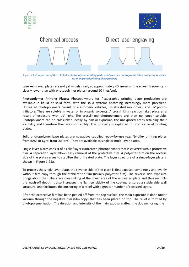
Rubber Plates; Rubber plates are produced by molding a matrix (embossed casting mold) using natural rubber with subsequent vulcanization. The plate is sometimes worked to an even thickness by grinding of the reverse side. The best quality rubber and elastomer plates are produced when the print image relief is applied by laser engraving to plate cylinders that have been fully coated with elastomer and then precision‐ground. With this process, the side walls of the printing elements can be shaped – in contrast to photo‐chemical production – so that only the foot is at a slant, to increase stability, and the upper area has a vertical side wall, so that any resulting dot gain is to a large extent avoided during abrasion of the plate during printing (Figure 23). [2]
DELIVERABLE 1.3 PROCESS MONITORING REQUIREMENTS 24/50
Figure 23: Comparison of the relief of a photopolymer printing plate produced in a photographic/chemical process with a
laser engraved printing plate (rubber)
Laser‐engraved plates are not yet widely used; at approximately 40 lines/cm, the screen frequency is clearly lower than with photopolymer plates (around 60 lines/cm).
Photopolymer Printing Plates; Photopolymers for flexographic printing plate production are available in liquid or solid form, with the solid systems becoming increasingly more prevalent. Untreated photopolymers consist of elastomeric vehicles, unsaturated monomers, and UV photo‐initiators. They are soluble in water or in organic solvents. A crosslinking reaction takes place as a result of exposure with UV light. The crosslinked photopolymers are then no longer soluble. Photopolymers can be crosslinked locally by partial exposure, the unexposed areas retaining their solubility and therefore their wash‐off ability. This property is exploited to produce relief printing plates.
Solid photopolymer base plates are nowadays supplied ready‐for‐use (e.g. Nyloflex printing plates from BASF or Cyrel from DuPont). They are available as single or multi‐layer plates.
Single‐layer plates consist of a relief layer (untreated photopolymer) that is covered with a protective film. A separation layer allows easy removal of the protective film. A polyester film on the reverse side of the plate serves to stabilize the untreated plate. The layer structure of a single‐layer plate is shown in Figure 1‐25a.
To process the single‐layer plate, the reverse side of the plate is first exposed completely and evenly without film copy through the stabilization film (usually polyester film). The reverse side exposure brings about the full‐surface crosslinking of the lower area of the untreated plate and thus restricts the wash‐off depth. It also increases the light‐sensitivity of the coating, ensures a stable side wall structure, and facilitates the anchoring of a relief with a greater number of recessed layers.
After the protective film has been peeled off from the top surface, the main exposure is done under vacuum through the negative film (film copy) that has been placed on top. The relief is formed by photopolymerization. The duration and intensity of the main exposure affect the dot anchoring, the

DELIVERABLE 1.3 PROCESS MONITORING REQUIREMENTS 25/50
side wall angle, and the intermediate depths in fine structures, such as halftone areas (Figure 24). [1]
Figure 24: Main exposure, effect of exposure time. (a) Dot anchoring (e.g., with line structures) by UV exposure; (b) Side wall angle and intermediate depth (with screened image elements); relief in the case of a 1.14 mm digiflex plate about 0.6–0.7mm, intermediate depth min. 70μm
Figure 25: Fig. 2.3‐7 Structure of the various flexographic plates. (a) Single‐layer plate (BASF); (b) Multi‐layer plate (BASF); (c) Plate for computer to plate imaging systems (digiflex, BASF)
DELIVERABLE 1.3 PROCESS MONITORING REQUIREMENTS 26/50
The main exposure is followed by the washing‐off process. The unpolymerized areas of the plate are dissolved with a solvent, with brushes supporting this dissolving process mechanically. After washing‐off, the plate has to be dried thoroughly, in order to evaporate any wash‐off agent that has penetrated the relief layer. This is followed by all‐over post‐exposure without film, in order to crosslink all parts of the relief completely. In this state, the flexographic printing plate has a sticky surface, on which dust and dirt would collect. This stickiness disappears as a result of exposure to UV‐C light or after immersion in a bromine solution. Now the flexographic printing plate is complete.
Single‐layer plates are made in thicknesses of 0.76mm (e.g., for printing on plastic bags, film, and fine cardboard products) to 6.35 mm (e.g., for corrugated board and heavy‐duty bags made from paper and film). Screen frequencies of up to 60lines/cm (150lpi) can be achieved with plates less than 3.2 mm thick. The possible tonal range here is about 2–95%. Thicker plates (around 4–5 mm) are suitable for screen frequencies of up to 24 lines/cm (60 lpi) with a tonal range of approximately 3–90%.
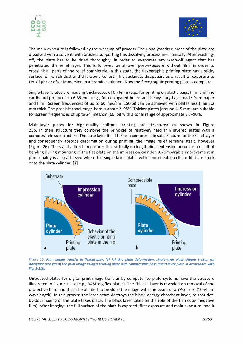
Multi‐layer plates for high‐quality halftone printing are structured as shown in Figure 25b. In their structure they combine the principle of relatively hard thin layered plates with a compressible substructure. The base layer itself forms a compressible substructure for the relief layer and consequently absorbs deformation during printing; the image relief remains static, however (Figure 26). The stabilization film ensures that virtually no longitudinal extension occurs as a result of bending during mounting of the flat plate on the impression cylinder. A comparable improvement in print quality is also achieved when thin single‐layer plates with compressible cellular film are stuck onto the plate cylinder. [2]
Figure 26; Print image transfer in flexography. (a) Printing plate deformation, single‐layer plate (Figure 1‐11a); (b) Adequate transfer of the print image using a printing plate with compressible base (multi‐layer plate in accordance with Fig. 1‐11b)
Untreated plates for digital print image transfer by computer to plate systems have the structure illustrated in Figure 1‐11c (e.g., BASF digiflex plates). The “black” layer is revealed on removal of the protective film, and it can be ablated to produce the image with the beam of a YAG laser (1064 nm wavelength). In this process the laser beam destroys the black, energy‐absorbent layer, so that dot‐by‐dot imaging of the plate takes place. The black layer takes on the role of the film copy (negative film). After imaging, the full surface of the plate is exposed (first exposure and main exposure) and it

DELIVERABLE 1.3 PROCESS MONITORING REQUIREMENTS 27/50
is further processed in the same way as a single layer plate in order to create the relief (no laser‐engraving takes place here, as was explained for the production of rubber plates).
Mounting the Printing Plate; The flat plates are fastened in accurate register onto the plate cylinder with double‐sided adhesive film. When doing this, the plate must be brought into the shape of a cylinder shell. The image dimensions have to be reduced in prepress in the direction of printing to compensate for the longitudinal increase in size.
Sleeve Technology; The principle of sleeve technology consists of a thin‐walled metal sleeve, the inside diameter of which is dimensioned so that the sleeve can be expanded under compressed air and pushed axially onto the plate cylinder. Once the compressed air has been turned off, the sleeve sits firmly on the plate cylinder by force fit. Before being pushed onto the plate cylinder, the entire outer surface of this sleeve is covered with plate base material. The cylindrical plate is directly imaged using lasers in a round imagesetter (Fig.27
Figure 27: Laser exposure of a sleeve printing master (digiflex, BASF)
With this process the longitudinal extension that takes place during conventional mounting and the inaccuracies connected with the attachment of the block do not occur.
There are two modes of procedure for sleeve technology:
• Covering the sleeve with a laser exposable plate cut exactly to the size of its cylinder casing,
in which case the sleeve has a seam.
• The use of seamless sleeves which have been already fully prepared by the manufacturer
with the relief layer (e. g., BASF digisleeve). [2]
Bar Code specifications
Bar code print specifications are produced by combining three types of related specifications:
1. Application Standards are published by accredited standards organizations.
Bar codes are used in many different applications with different scanning conditions. For example, one application involves packaging for retail checkout lanes while another application is for coding shipments for conveyor lane routing in distribution centres. The specifications for bar codes used in these two applications are different because the conditions for scanning the bar codes are different.

DELIVERABLE 1.3 PROCESS MONITORING REQUIREMENTS 28/50
Accredited standards organizations provide specifications in the form of guidelines and standards to assist in:
- Selecting the bar code type to be used, - Structuring the data inside the bar code, - Defining the printed human‐readable information that is inside the bar code, - Selecting bar code size within the acceptable range, - Understanding where the bar code should be placed on the product, and - Defining the minimum print quality requirements.
2. FIRST Print Specifications prescribe a minimal level of capability for all compliant printers.
These specifications fall within the acceptable limits of the appropriate Application Standard for the bar code being printed and will assist in:
Determining the minimum size for a bar code depending on the printing press and substrate, and identifying the preferred bar code orientation given the direction the web or sheet will travel.
3. Job Specifications should be published for film or plate output.
These specifications should assist in:
- Identifying optimum film/plate output resolution, and - Determining bar width reduction (BWR) required by the specified print conditions.
Figure 28 Colour Considerations: The optimum bar code colour combination is opaque black ink for the bars and opaque white substrate or ink for the background. [11]
Handling Flexographic printing plates
The printing plates provided are high‐quality flexographic printing plates. Please note that they can hold a considerable value.
Flexographic printing plates are designed for the mechanical strain in the printing press. If subjected to any form of improper strain outside the printing press, the quality of the plate and thus the print may be affected. The finest printing elements, such as halftone and fine line elements are particularly influenced by adverse mechanical effects. Digital printing plates are more sensitive than analogue printing plates due to their small detail and must therefore be handled with particular care. [1]

DELIVERABLE 1.3 PROCESS MONITORING REQUIREMENTS 29/50
Goods inward; Make sure the packaging of the delivered material is correct. The plates have to be placed back‐to‐back and the printing surface must be protected with foam. In order to prevent indentations or similar damage, plates should not be stacked in too large quantities on top of each other (depending on size and weight/thickness) and should not be packed too tightly. Digital printing plates are more sensitive than analogue plates in some parts of the images.
The quality of a printing plate in conjunction with printing ink is determined by the surface quality. The plates therefore usually have a certain degree of residual adhesiveness when used properly. For this reason, it is important the plates are not placed directly on top of each other as they may otherwise become stuck. On delivery, the individual printing plates are protected by a layer of material placed between each one. This should be kept in place as far as possible.
The printing plate maker must also take care not to finish the printing plates too strongly as this may cause light cracking in the background and on the surface. A certain smell from residual solvent, although not pleasant, is unavoidable. It does however decrease constantly over time and is not to be regarded as a health risk. [1]
Preparation for printing; Generally the printing plates are checked for the relevant parameters at the print preparation stage in order to ensure that further processing runs smoothly. The printing plates which are carefully produced and packed by the trade shop may be subjected to the first stress during this inspection, e.g. by being stacked or creased. This should be avoided. [1]
Mounting plates; Before the printing plates can be mounted, they should be given time to compensate for any climatic fluctuations during transportation and when being passed on into the printing shop as temperature and air humidity has an effect on the polyester backing material. In practice, printing plates are still quite often “distorted” which can be traced back to ambient climate related problems. Later problems with the register can then not be ruled out.
During the mounting process it is important not to apply too much pressure to the surface. A soft foam helps to distribute the pressure evenly and prevents friction on printing elements in the highlight tonal range which are sensitive on both analogue and digital plates. The position should not be frequently adjusted by repeatedly removing the plates from the adhesive tape.
If a final test proof is made, the proof printing ink must be removed from the surface carefully. This is best performed using a soft, lint‐free cloth and not using brushes. Special proof inks can be washed off with water. Substances which contain oil or acetate must not be used. The printing surface in halftone areas must be dabbed and not rubbed. The polymer should in general be given enough time after each contact with ink/cleaning agent for the liquids to evaporate. [1]
Printing process; Cleaning poses the biggest danger for the printing plate. In addition to problems during mounting, such as rubbing/friction on the surface and the related losses in the finest printing elements, at this further stage the printing plates are also exposed to solvents and, in the case of other ink systems, such as UV curing systems, the effects of other components in the printing ink. The incorrect solvent or cleaning agent can cause, for example, everything from swelling and the possible loss of parts of the image to register problems in repeat jobs.
Photopolymer printing plates are subject to high levels of mechanical force from the application of the print, from forced control on gearless printing presses, between the impression cylinder and anilox roller. This force is increased exponentially if the surface speeds do not match. This
DELIVERABLE 1.3 PROCESS MONITORING REQUIREMENTS 30/50
mismatched ratio can be caused by the height of the printing plate being incorrect (printing cylinder diameter, sleeve diameter, thickness of adhesive tape, thickness of printing plate), the anilox roller and/or the impression cylinder being applied incorrectly, the use of an anilox roller with the incorrect diameter or the use of substrate which is too thick or thin (relative to the dimensions of the impression cylinder). Premature wear and tear or the breakup of small elements of the design may be caused as a result.
The trend in anilox roll technology is towards finer lines with higher volume. Even with more coarse engravings it is important that the ceramic coating is of an even thickness and has a low level of porousness. A homogenous formation of cell walls stabilises the halftone dots especially with digital or point light exposed printing plates.
Most factories use a mix of both analogue and digital printing plates. If they are not labelled accordingly, the printer does not know whether he is working with digital or analogue plates and cannot therefore deliberately apply the appropriate precautionary measures. It is therefore very important that sets of printing plates are marked permanently. [1]
Cleaning and archiving; The statements made for mounting and printing are equally valid here, too. Whether the printing plates remain on the sleeve or are stored flat ‐ they must be protected from pressure and light.
The appropriate cleaning agents for the type of plate must be volatilised before storage. If a cleaning machine is used, the stiffness of the brushes and the pressure applied by the brush and spraying systems must be checked before use with digital printing plates. Special cleaners may contain a higher concentration of corrosive solvents which will attack the structure of the printing plates. The printing plates should be powdered before storing. Climatic fluctuations during storage lead to later problems with the register and thickness tolerances. The date of storage should be recorded. [1]
3.2.5. Process control in Flexographic printing
For consistent, repeatable product – in the case of ECOFLEXOBAG a flexible bag – there must be allocated (either on the design or in the waste matrix of the job) to accommodate an appropriate control target. The same control target (run target) included on all optimization, fingerprint and characterization trials must also be included on “live” jobs. It is impossible to control what is not measured. By measuring the process control parameters (print density, dot gain, gray balance, as well as print contrast, Total area coverage, spot colour, bar code scan rate, etc) and key mechanical control parameters (ink viscosity, pH, film surface tension, etc) and comparing the results – in real time – to the average and control limits established from the fingerprint data, it is possible to control the printing process for repeatable results. Realtime control charting, with appropriate training, makes it easy for press crews to determine when press adjustments are necessary and, as importantly, when they are not necessary to maintain print quality and consistency. Overadjusting a press can actually increase the amount of variation in print quality and generate more scrap and downtime. Basic statistical training clarifies for press crews what variation is inherent in the process – and therefore, should not attempt to correct – and what variation is due to a change in the process (special cause) – and therefore, should be corrected. [1]
• Press Maintenance – A properly maintained press is capable of achieving similar print results run after run. However, a press in need of maintenance will have a difficult time duplicating

DELIVERABLE 1.3 PROCESS MONITORING REQUIREMENTS 31/50
previous results. Press maintenance is an example of “special cause variation” which must be corrected in order to print “in control”.
• Process Documentation – Strong documentation systems make it easy to monitor and control the components coming to press and to set‐up and run the press the same way every time a job is run. Some examples of process documentation that help to reduce variability include:
o Press Operating Data Sheet – Ensures the press is set‐up and run the same way every time.
o Anilox Roll Identification Code & Card – By labelling each individual anilox roll with a unique code, the printer can ensure the same roll is put in each deck ‐ not just the same cell count, volume, and angle. The card that accompanies the anilox roll includes manufacturer, date new, date last cleaned, cell count, screen angle, and actual cell volume measurement. The anilox roll card makes it easy to determine the last time a roll was cleaned, how old it is, and the latest volume measurement.
o Printing Plate Labelling & Card – Each printing plate should have clearly imaged, in a non‐print zone, the appropriate CMYK, Spot 1, Spot 2, etc. label. This provides a quick and easy check throughout the manufacturing process to confirm each plate is printing in the correct deck. Also, the plate card tracks date new, plate type, each date it is used, and the number of impressions on the plate. This information helps to determine when a plate should be replaced and the plate material to use when making a replacement plate. [1]
Throughout the press run, the press crew should measure and record, on a standardized form, spreadsheet, or database, the process control parameters and appropriate mechanical control parameters. This information is used, real‐time, to control the printing process.
Standardized printing plate production
This section provides information on the manufacturing, specifications, tolerances, and measurement methods for the three main types of flexographic printing plates:
- Single‐layer plate - Multi‐layer plate - Plate for computer to plate imaging systems
This information will assist the print production team in selecting the most appropriate printing plate to best produce the design and ensure consistent performance.
Flexographic plates are supplied by the manufacturer in a variety of forms, which determines the platemaking process required to produce a press‐ready flexographic printing plate. [1]
Imaging and processing parameters; In order to establish optimum imaging parameters, it is imperative to check the Laser focus settings. To do so, follow the instructions of the manufacturer. In certain circumstances this function may not be necessary or available if an automatic focus is in use. To optimise the fundamental laser power balance, image the DFTA CtP strip in the pixel version and appropriate platesetter´s resolution several times side by side.
Depending on the utilized platesetter´s capabilities the individual imaging settings are supposed to differ either in the energy setting of the laser or in the rotation speed of the drum.

DELIVERABLE 1.3 PROCESS MONITORING REQUIREMENTS 32/50
Figure 29: DFTA CtP control strip. [12]
For more detailed information, please contact the manufacturer of your platesetter. The evaluation of the optimum laser power balance may be performed as follows. Visual evaluation should be recommended due to its ease‐of‐use and precision.
Flexographic printing plates require a certain relief depth, therefore the settings in the plate processor must be held constant and it must be assumed that a certain brush pressure is constantly set per every plate thicknesses.
The thicknesses of the finished flexographic printing plates are very important for the printing process as larger fluctuation within the printing plates contained on one print cylinder can only be compensated with great difficulty and usually with clear loss of quality. It is therefore very important to perform an inspection regularly of the printing plates produced. Using a thickness measuring device is indispensable to determine the optimum washing time. It is also important that the measuring device used in each case is suitable for the purpose. Thus, devices which apply a large degree of pressure on the soft elastic samples being measured should be avoided. They may deform the printing plate material considerably and thus distort the measurements. They are particularly unsuited to measurements in halftone tints.
Print quality in flexographic printing
The print quality that can be achieved in flexographic printing is lower than the achieved in gravure and offset printing. The resolution is generally lower with flexography (48 lines/cm) than with offset which has a standard of 60 up to 120 lines/cm. [2] Mottling and optical print density variations in full tones are critical in flexographic printing, due to the low ink transfer.
When designing the fingerprint test form, the test elements typically included can be divided into two general categories:
• Process Control Parameters/Elements, which indicate the print capability of a particular press, operating with specific settings and materials as required by the graphic design. These test elements measure key quality attributes of the graphic design. Typical process control parameters on a fingerprint test form include: o Solid Colour Patches
Process Colours: With process printing, the solid test patches represent important “anchor points” for the colour reproduction process, so it is important to quantify them. The process colour solids can be measured using both densitometry (solid ink density) and spectrophotometry (L*a*b*C*hº).
Custom/Spot Colours: Using the best press set‐up and ink formulation (as determined during the optimization process), quantify, using spectrophotometry (L*a*b*C*hº DE) and visual evaluation, how well the printing process is able to match the specified

DELIVERABLE 1.3 PROCESS MONITORING REQUIREMENTS 33/50
colour. A sample of the fingerprint test form, printed with the same substrate, press, ink formulation, etc. as future production, should be sent to the customer for colour approval. Once approved, the solid custom colour printed on the fingerprint test form should be used to create the “standard” in the colour measurement software to which all “live” jobs will be compared.
o Gray Balance Patches: This test element should include patches representing highlights, 1/4‐tones, mid‐tones, 3/4‐tones and shadows. Gray balance is influenced by the colour and density of the process inks, dot gain, and ink trapping. It is the most sensitive parameter to monitor and the easiest to evaluate visually. While gray balance will not identify which variable has deviated, it is the first place where a change in the printing process is usually detected.
o OverprintTrap Patches: These patches are used to assess how well inks trap, or print over one another. In addition to the process colour solids, process colour overprints (red, green, blue) represent additional “anchor points” in the colour reproduction process. They can be quantified either densitometrically (trap equations) or colorimetrically (L*a*b*C*hº). Also, if there are any non‐process overprints (spot with process, spot with spot), they should be quantified as well. Traps should appear smooth and free of pinholes. Refer to Print Section 20.4.6 for additional information.
o Tone Scales: Tone scales are flat tints typically ranging from 2%, as measured in the film/file, to as much as 98%. They can be used to measure dot area, dot gain, print contrast, and tint density. Regardless of the measurement equations used, it is important to understand how halftone dots are reproduced on the press and to quantify the results (establish aim points and tolerances) for future runs. In addition to evaluating tone compression, tone scales are useful for identifying the best screen ruling and screening technology (conventional/stochastic/ hybrid) for the design requirements.
o Vignettes: A vignette is a continuously graduated scale that smoothly transitions from a solid to the minimum dot held on the plate. Vignettes may be included in several screen rulings to visually determine the optimum ruling to use on “live” jobs given the press set‐up and design parameters.
o Bar Codes: For the appropriate symbology, include several different combinations of magnification (size) and BarWidth Reduction (BWR). Orient the symbols in both the web and cross directions to determine the optimum combination to use on the “live” jobs given the press set‐up and design parameters.
o Line & Type Elements: These test elements are used to determine the minimum type size and rule width to use on “live” jobs given the press set‐up and design parameters. These elements should be printed on every deck since the minimum printable size will vary with deck set‐up conditions. The test elements should include both positive and reverse lines/rules and serif & sans‐serif fonts. Include the point size of each line of text for easy identification. [1]
• Mechanical Control Parameters/Elements are used to ensure the press is mechanically operating as it should be. These elements should be included in several places across the fingerprint test

DELIVERABLE 1.3 PROCESS MONITORING REQUIREMENTS 34/50
form (gear, centre & operator sides) to ensure the press is balanced across the sheet/web. Typical mechanical control parameters on a fingerprint test form include: o Impression & Slur Targets: These elements evaluate plate‐to‐substrate and anilox‐to‐plate
impression, ink volume, ink dry rate, and fluting (in corrugated applications).
o Plate Exposure Guides: These test elements confirm optimum exposure and processing of the printing plates.
o Registration Targets: There are several registration targets used to determine the accuracy and consistency of colour‐to‐colour registration on press. These test elements also monitor the position of the image (centre marks) and confirm the image is square to the lead edge (in corrugated and envelope blank applications).
o Solid Ink Colour Patches: In addition to the process control parameters that are evaluated using these test elements, they can also be used to evaluate mechanical control parameters such as anilox‐to‐plate and plate‐to‐substrate impression.
o Vignettes: Vignettes can also be used to identify defects that result in light and dark areas, or bands that stretch across the entire web/sheet width. Common names include barring, gear marking, or gear chatter. This defect is typically attributed to gear problems, form layout, or doctor blade chatter. There can also be localized banding problems as a result of imaging problems in platemaking. Higher line screens are more likely to show barring.
o FlatTint: This test element is very useful to quickly identify press problems during the fingerprint trial associated with: ink volume & dry rate, anilox volume, bad bearings, plate impression settings, and fluting (in corrugated applications). The printer should select the best tint for their operation; a 30% ‐35% tint is typical. [1]
3.3. Bags manufacturing (Cutting and converting) After the printing process is complete, the large roll of film is then cut to size with hot knives that seam the sides of the bags together when cut.
Then, the film is fed into bag manufacturing machines where the top and bottom seals are formed and the handles are cut out. All of internal „scrap” is usually then reintroduced into the manufacturing process as a closed loop system to eliminate any wasted material.
There are four basic sealing methods:
• sideweld seal, • bottomseal, • twinseal, • slit seal.
DELIVERABLE 1.3 PROCESS MONITORING REQUIREMENTS 35/50
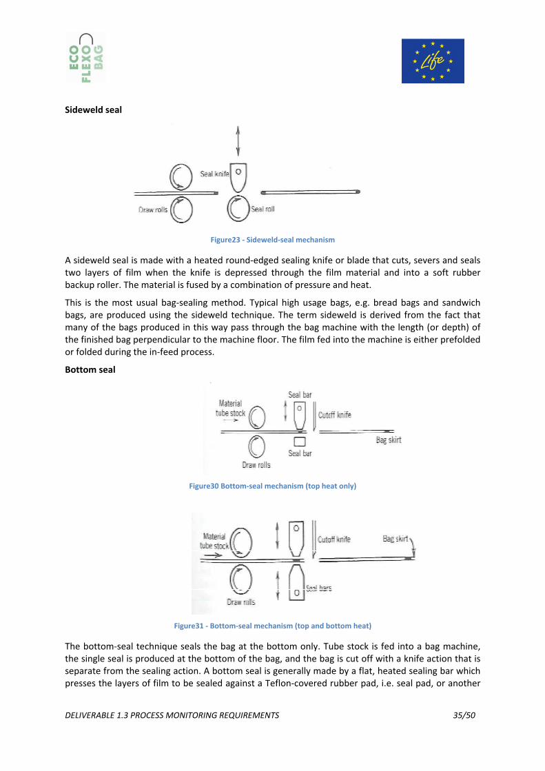
Sideweld seal
Figure23 ‐ Sideweld‐seal mechanism
A sideweld seal is made with a heated round‐edged sealing knife or blade that cuts, severs and seals two layers of film when the knife is depressed through the film material and into a soft rubber backup roller. The material is fused by a combination of pressure and heat.
This is the most usual bag‐sealing method. Typical high usage bags, e.g. bread bags and sandwich bags, are produced using the sideweld technique. The term sideweld is derived from the fact that many of the bags produced in this way pass through the bag machine with the length (or depth) of the finished bag perpendicular to the machine floor. The film fed into the machine is either prefolded or folded during the in‐feed process.
Bottom seal
Figure30 Bottom‐seal mechanism (top heat only)
Figure31 ‐ Bottom‐seal mechanism (top and bottom heat)
The bottom‐seal technique seals the bag at the bottom only. Tube stock is fed into a bag machine, the single seal is produced at the bottom of the bag, and the bag is cut off with a knife action that is separate from the sealing action. A bottom seal is generally made by a flat, heated sealing bar which presses the layers of film to be sealed against a Teflon‐covered rubber pad, i.e. seal pad, or another

DELIVERABLE 1.3 PROCESS MONITORING REQUIREMENTS 36/50
seal bar. A separate cutoff knife is used to separate the bag from the feedstock while the seal is made or immediately thereafter.Both bottom‐seal mechanism designs produce a bag with only one seal, unless the tube has been manufactured by slit‐sealing (see below). The small amount of unusable, wasted film between the edge of the seal and the cutoff point, called the „skirt” of the bag, is an important factor in the total cost of the bag. Any disadvantage caused by the presence of the unwanted skirt are usually offset by greater control of the sealing process.
The bottom‐seal method is commonly used to produce HDPE merchandise bags and LDPE industrial liners, trash bags, vegetable and fruit bags, and many other types of bags supplied in a roll. In contrast to the sideweld method, designed primarily for high‐speed production of bags made from relatively light‐gauge films, i.e. 13‐51 µm, bottom‐seal methods are often used to produce bags from film from 13‐ 150 µm at slower production speeds. Bags manufactured by bottom‐seal methods are delivered through and out of the bag machine with the length (or depth) of the bag parallel to the machine direction. Since all of the bags are produced from tube sock, multiple‐lane production of bags is limited only by the widths of the machine and the bags and the film‐handling capability of the bag machine.
Twin seal
The twin‐seal method employs a dual bottom‐seal mechanism with a heated or unheated cutoff knife located between the two seal heads. The unique feature of the twin‐seal mechanism is that it supplies heat to both the top and bottom of the film material and makes two completely separate and independent seals each time the seal head cycles.
Figure32‐ Twin‐seal mechanism
Like the bottom‐seal method, the twin‐seal technique can supply a large amount of controlled heat for a given duration. This makes the twin seal useful in sealing heavier‐gauge films as well as coextrusions and laminates. Since two seals are made with each machine cycle, the twin‐seal method can be used to make bags with the seals on the sides of the finished bag, i.e. like sideweld bags, or on the bottom of the bag in some special applications, such as retail bags with handles. Many special applications call for the use of a twin‐seal type sealing method, but it is most often used in the production of the plastic „T‐shirt” grocery sack.
Slit seal
Another type of sealing method, the slit seal, involves sealing two or more layers (usually only two) of film together in the machine direction through the use of a heated knife, hot air, laser beam, or a combination of methods. The slit‐seal technique is usually used to convert a single large tube of film into smaller tubes. In the production of grocery sacks, for example, a single extruded 152 cm lay‐flat tube of film can be run through two slit sealers in line with the bag machine. This results in three tubes of 51 cm lay‐flat material being fed to the bag making system.

DELIVERABLE 1.3 PROCESS MONITORING REQUIREMENTS 37/50
Figure24 ‐ Slit sealer (hot‐knife type): Left: Side view; Right: Top view
3.4. Technical Procedures
3.4.1. Standard Layouts Standard layouts should be used to minimize waste both in the print process and during further processing. For example arrows can be placed in the bearer bars or outside cutter guides to ensure print is always heads up to the converting equipment. Ideas like this should be included in the standard layout in collaboration with the converter so that overruns can be minimized.
3.4.1.1. Colour Management
Colour management is of paramount importance, poor colour management results in large waste production caused by, for example, extended set up times or customer rejection.
In order to achieve consistent colour control, gamut profiling of each input device (scanner, design) and output device (proofer, press) should be conducted. Colour management software then transforms the output profile so that it matches the input. Good colour management will also include ink supplier certification of supplied ink to specified tolerances. In house colour mixing will also be supplied to press within a given tolerance and with colour chips for colour matching on press.
3.4.1.2. Standard Operating Procedures
Standard operating procedures detail the optimum methodology for conducting a particular task. The SOP which should be written in consultation with operators ensures optimum performance, maintains consistency and retains knowledge ‐ should personnel leave. The SOP should be regularly updated so that any improvements identified are recorded.
3.4.1.3. Ink Tank Volume Reduction
Ink tanks often require a set volume of ink to prime and run the system, when using spot colours this could be significantly larger than that actually required to produce the job. Ink tank volume can be reduced simply by inserting a rubber brick or using a variable volume ink tank so that a minimum of press ready ink can be produced saving on ink wastage due to overproduction.
3.4.2. Overlooked Techniques
3.4.2.1. Energy Reduction
When considering the lifecycle of bag production, reducing the use of energy at the printing stage will contribute to a reduction in the overall carbon footprint. Therefore any system that can be applied to the production process should be considered for BAT. Systems for the reduction in energy use are suggested in this section.
3.4.2.2. Switch Off When Not in Use
In principle the concept of switching off equipment when not in use is simple, however many items of equipment will be left on or in standby when not in use. For example when the press is not running web cleaners, antistatic equipment, registration and inspection cameras and sensors (web

DELIVERABLE 1.3 PROCESS MONITORING REQUIREMENTS 38/50
break, web alignment etc) will remain working when they could be switched off. Dryers will also continue working at reduced power however this may be necessary to remove solvents during set up.
Off press equipment that may be left in operation or standby are cleaning equipment, compressors, cooling systems. Cleaning equipment like ultra sonic cleaners may be left on in preparation while a job is running and the principle also applies to all areas of the production plant including lighting, air‐conditioning, computing equipment and automatic flush systems in lavatories.
The BAT would therefore be to survey the plant and identify any equipment that is routinely left on when not in use and systems put in place to reduce the occurrence. This could be included in standard operating procedures or automation.
3.4.2.3. Centralized Systems
In many cases it will be possible to reduce energy use by using centralized systems. For example consideration should be given to a centralized compressor system. This reduces energy consumption as a centralized compressor system is more efficient than multiple small compressors at point of use.
3.4.2.4. Minimum Dryer Requirements
The specific requirements for drying/curing will vary from colour to colour and job to job therefore a BAT should be considered where the dryer settings are adjusted for each job/ colour individually. With good communication between press and pre press operators, job and colour specific dryer settingscan be included in the job file. The dryer system should also be linked to press speed so that the dryer power is ramped with speed.
Dryer power is usually thought of in terms of temperature; however increased airflow will increase osmotic potential ‐ increasing the rate of drying. Consideration should therefore be given to increasing airflow as a less energy intensive means of improving drying than increasing temperature. However this should be done with the understanding that some dryers must retain a certain solvent content to maintain waste gas treatment efficiency.
Residual Solvent Removal by Final Dryer
In BREF STS it is stated that a residual solvent content of typically 2‐3% remains in the dry ink film and this solvent should be removed with higher dryer power. This residual solvent could however be removed using only the final dryer in the print sequence, avoiding the need for high power on all inter unit dryers. The same principle can be applied with UV cured inks where a complete cure is only achieved at the final unit.
3.4.2.5. Weight Reduction
Reduction of weight has an energy saving. An example of this is the use of reduced weight gravure cylinders or sleeves. A gravure sleeve can weigh 7kg where a standard cylinder would weigh 225kg[16] this large weight reduction provides several environmental benefits. The reduced weight is an operational improvement as lifting and transport equipment such as cranes can be eliminated and changeover speed can be increased reducing press downtime. An additional benefit is reduced storage and transportation requirements, the lower weight will require less fuel usage in transportation between the plant and engraver.

DELIVERABLE 1.3 PROCESS MONITORING REQUIREMENTS 39/50
4. Requirements of Commercial Bags production process
In this chapter, aspects to be taken into account and monitored during the production of printed commercial bags are identified based on survey that have been carried out within the project, analysis of legislation and experience from previous projects.
The following groups of requirements are considered:
• Mechanical requirements • Film processing requirements • Printing requirements • Legislative requirements • Environmental requirements • Economic, productivity and quality requirements
As a next step, the most relevant key aspects will be selected and used to determine concrete procedures for production process monitoring in the following project steps (Action B.3 Determination of procedures for monitoring the sustainable production of commercial bags).
4.1. Mechanical requirements Materials used in Commercial Bags production process are characterised by the following main properties:
• Thermal properties: Melting temperature, sealing conditions, etc.; • Physical properties: Density, surface tension, etc.; • Mechanical properties: Tensile strength, elongation, tear resistance, static and dynamic load
resistance, coefficient of friction, etc.
It is important to maintain the main properties, namely strength properties, when sustainable substrates are used. While recycled materials provide more or less the same strength, some producers report that biodegradable plastic bags do not reach the same strength as conventional bags made from virgin material and stretch.
The main mechanical requirements to be considered include:
• Viscosity • Temperature profile • Speed of the press • Extrusion speed • Extension ratio • Melt temperature control • Melt pressure control • Torque control • Blow‐up ratio • Fast ink transfer to the printing plate • Thickness of plates • Hardness of plates

DELIVERABLE 1.3 PROCESS MONITORING REQUIREMENTS 40/50
• Flexibility of printing plates • Pressure between the aniloxrol and printing plate and substrate • Nature of the substrate surface – substrate characteristics • Amount of volatile organic compounds • Production speed • Accuracy • Orthochromatis density • UV density less • Black maximum density
4.2. Film processing requirements
Before the printing plates can be mounted, they should be given time to compensate for any climatic fluctuations during transportation and when being passed on into the printing shop as temperature and air humidity has an effect on the polyester backing material. In practice, printing plates are still quite often „distorted” which can be traced back to ambient climate related problems. Later problems with the register can then not be ruled out. To maintain the necessary even pressure in the printing nip, the central impression cylinder must be manufactured with a low runout of less than 5μm and be temperature controlled with a tolerance of +/–1°C (in the case of a 1.80m diameter steel cylinder, for example, 1°C difference in temperature brings about a difference in the radius of approximately 10μm).
Extension ratio is the ratio between the speed of collection of the film and the lineal extrusion speed, and therefore tells us the degree of longitudinal extension. It needs to be greater than the blow ratio for better balloon stability control. The extension ratio is what controls the gauge or thickness of the film. The maximum extension ratio is around 1:25.
Flexographic presses are run at speeds up to 800 m/min, and presses able to print at 1000 m/min are now appearing on the market. The printing speed, however, also varies greatly depending on type of press and material being printed. Both sheet‐fed and web presses are used in flexographic where two to eight printing units are arranged around a single central impression cylinder. The other basic types of flexographic presses are stack and inline.
The main control parameters to be considered in blown film extrusion are:
• Temperature profile • Extrusion speed • Extension ratio • Melt temperature control • Torque control • Melt pressure control • Blow‐up ratio
4.3. Printing requirements
The printing requirements of the Commercial Bags are not so exhaustive for supermarkets. Customers expect a high quality reproduction of their logo but are not looking for more complex

DELIVERABLE 1.3 PROCESS MONITORING REQUIREMENTS 41/50
graphics.Mainly Commercial Bags are printed with single colour printing and they don´t need process colour printing.
However, Commercial Bags for more expensive products have higher printing requirements, for instance:
• Hue and intensity of every color should be correct and consistent. (Appropriate color management);
• The global positioning of the print should be ‘in register’ – exactly the correct position; • Inks may not transfer off the bag surface (not under mechanical tension, friction or under
heat pressure); • Adhesive strength of the ink; • Colour requirements; • Smooth printing quality.
With sustainable substrates (oxe‐degradable, recycled material), a bag surface is rougher which results in lower printing quality (less sharpness/resolution, true color). This fact is often accepted by clients, and the printed image is then adjusted to show that the bag is recycled. Better printing quality can be achieved with Biodegradable plastic; but new materials are under development for the time being.
When the bag contains some part of recycled material, the bag is not purely whitewhich is understood by clients (they accept the grey colour of bags).
Main printing requirements:
• Viskosity of inks • Thin, highly fluid and rapid‐drying inks • Ink film thickness • Printing width, length • Printing on both sides • Transfer characteristics of the ink • Printing speed • Temperature of drying • Consumption of electricity
4.4. Legislative requirements Industrial Emissions Directive (IED) 2010/75/EU
Industrial production processes account for a considerable share of the overall pollution in Europe (for emissions of greenhouse gases and acidifying substances, wastewater emissions and waste). In order to take further steps to reduce emissions from such installations, the Industrial Emissions Directive (IED) has been introduced.
The IED is the successor of the IPPC Directive and aims at minimization of pollution from various industrial sources throughout the European Union. Operators of industrial installations operating activities covered by Annex I of the IED are required to obtain an integrated permit from the authorities in the EU countries. Permit needs to contain permit conditions including emission limit

DELIVERABLE 1.3 PROCESS MONITORING REQUIREMENTS 42/50
values (ELVs) for all relevant pollutants, which are to be based on the use of the best available techniques (BAT).
The IED entered 6/1/2011; the Member States were obliged to fully transpose the Directive by 6/1/2013. The Directive applies to all new installations from this date onwards. All existing installations previously subject to IPPC, WI, SE and TiO2 Directives must meet the requirements of the IED by 6/1/2014. Large Combustion Plants (LCP) do not yet need to meet the new ELVs.
BAT reference document (BREF) already exists for Organic Solvents Printing, including requirements in relation to air emissions (namely VOC), energy consumption and resources, waste and waste water.
VOC Directive
The Council Directive on the limitation of emissions of volatile organic compounds due to use of organic solvents in certain activities and installations 1999/13/EC (VOC Directive) aims at prevention and reduction of both direct andindirect effects of emissions of volatileorganic compounds into the environment,mainly into air, and the potential risks tohuman health.
Printing according to this directive means any reproduction activity of text and/or images in which, with the use of an image carrier, ink istransferred onto whatever type of surface. It includes associated varnishing, coating and laminating techniques. However, only the following sub‐processes are subject to the Directive:
• Flexography ‐ a printing activity using an image carrier of rubber or elastic photopolymers on which the printing areas are above the non‐printing areas, using liquid inks which dry through evaporation,
• Heatsetweb offset ‐ a web‐fed printing activity using an image carrier in which the printing and non‐printing area are in the same plane, where web‐fed means that the material to be printed is fed to the machine from a reel as distinct from separate sheets. The non‐printing area is treated to attract water and thus reject ink. The printing area is treated to receive and transmit ink to the surface to be printed. Evaporation takes place in an oven where hot air is used to heat the printed material,
• Laminating associated to a printing activity ‐ the adhering together of two or more flexible materials to produce laminates,
• Publication rotogravure ‐ a rotogravure printing activity used for printing paper for magazines, brochures, catalogues or similar products, using toluene‐based inks,
• Rotogravure ‐ a printing activity using a cylindrical image carrier in which the printing area is below the non‐printing area, using liquid inks which dry through evaporation. The recesses are filled with ink and the surplus is cleaned off the non‐printing area before the surface to be printed contacts the cylinder and lifts the ink from the recesses,
• Rotary screen printing ‐ a web‐fed printing activity in which the ink is passed onto the surface to be printed by forcing it through a porous image carrier, in which the printing area is open and the nonprinting area is sealed off, using liquid inks which dry only through evaporation. Web‐fed means that the material to be printed is fed to the machine from a reel as distinct from separate sheets,

DELIVERABLE 1.3 PROCESS MONITORING REQUIREMENTS 43/50
• Varnishing ‐ an activity by which a varnish or an adhesive coating for the purpose of later sealing the packaging material is applied to a flexible material.
Installations subject to the VOC Directive has to demonstrate that they fulfil relevant emission limit values in waste gases, fugitive emissionvalues and total emission limit values or the requirements of the reduction scheme. A Solvent Management Plan can be established by the installation in order to demonstrate compliance with these requirements.
In 2004, the Directive on the limitation of emissions of volatile organic compounds due to use of organic solvents in certain paints and varnishers and vehicle refinishing products (2004/42/EC) was published. It amends the VOC Directive and its aim is to limit the total content of VOCs in certainpaints and varnishes and vehicle refinishingproducts in order to prevent or reduce airpollution resulting from the contribution of VOCsto the formation of tropospherical ozone.
Waste Management Directives
In 1999, the Landfill Directive was published with the main aim to prevent, or minimise the negative effects on both the environment and human health caused by landfilling of wastes. The directive requires the amount of biodegradable municipal solid waste sent to landfill to be reduced
• to 75% of 1995 levels by 2010; • to 50% of 1995 levels by 2013; • to 35% of 1995 levels by 2020.
Packaging and Packaging WasteDirective (and amendments) requires packaging to be minimised and designed for recovery and re‐use, and sets recovery targets to be met by the European countries for waste packaging. Heavy metals in packaging are restricted.

DELIVERABLE 1.3 PROCESS MONITORING REQUIREMENTS 44/50
Waste Management Plans
In several countries, national plans in a field of waste management exist dealing with issue of packaging including Commercial Bags. Targets relating to reduction of their use and replacement by biodegradable bags are often set.
On the other hand, plastic bags are not included in the EU Green Public Procurement criteria nor the EU Ecolabel product groups exist.
Main legislative requirements:
• Production according to Industrial Emissions Directive • Production according to VOC Directive • Production according to Waste management legislation • Production according to national waste management plans
4.5. Environmental requirements The main environmental concernsin Commercial Bags are the consumption of resources caused by the increasing consumption of these products, VOC emissions and waste‐related issues.
While some commercial distributors ask their suppliers to provide sustainable Commercial Bags, others do not set any specific environmental criteria. However, when recycled or biodegradable materials are demanded, often proof in a form of certification is required.
Plastic bags made from recycled material appear to be the most favourable alternative. Unlike the results of earlier studies, cotton bags did not emerge as the best product, the reason for this being the substantial amount of energy and irrigation water required in cotton production, and the resulting greenhouse gas emissions. Biodegradable plastic bags turned out to be the worst alternative due to the fossil ingredients which are added to their material mix to enhance stability. Their biodegradation, whether through composting or as landfill waste, has a negative effect on the climate.
Main environmental requirements:
• Reusable bags • Using recycled PE • Compostability • Certification of reusable commercial bags • Biodegradable materials • Oxo‐biodegradable materials • Recyclability • VOC emissions • Energy consumption • Water consumption
4.6. Economic, productivity and quality requirements
Economic factors have to do with the economical sustainability of a process. Nowadays, economic sustainability (long term profit) has become mixed with other aspects of sustainability (people, planet). This is due to the increased importance of stakeholders such as a company’s employees

DELIVERABLE 1.3 PROCESS MONITORING REQUIREMENTS 45/50
(people make the difference) and volatile customers with rapidly shifting perceptions and values (CSR, planet). This means that an effective set of indicators will not only be concerned with immediate profits (added value, delivery time, turnover, etc.) but also with planet and people aspects.
Facts are best expressed in numbers as they are unambiguous. It is important to only measure the data that directly contributes to the desired final result. In practice, it is often found to be difficult to connect strategic‐level goals to specific units on the work floor (work place / cell / unit).
The desire is to control and monitor in increasing detail (from strategic level to departments (or product types/families) to finally the machine level) in such a way that there is a strong connection between high‐level measurements and detailed measurements. As the level of detail increases, the technical nature of performance indicators also increases.
The different aspects in the company that need to be controlled (expressed as KPI’s) are relevant for the company as a whole and therefore relevant for every employee – but not every employee will be able to work with them. Financial controllers do not run machines, the management doesn’t measure the temperature of a machine, a machine maintenance crew does not receive feedback about customer satisfaction. It is therefore appropriate to separate KPI’s and place them where they are relevant, as long as the connection between the KPI’s is ensured. Everything must work towards the common goal. Specific goals for departments or machines are ever more related to individual companies, but in general a division can be made of KPI’s into the strategic, operational and machine level. This division ranges from high‐level to detailed level.1
1 More detailed division of KPI’s into the strategic, operational and machine level is provided in Annex I.

DELIVERABLE 1.3 PROCESS MONITORING REQUIREMENTS 46/50
5. Conclusions
Production of printed Commercial Bags consists of several production phases, in which various aspects have to be considered and controlled in order to achieve the highest effectiveness and efficiency of the process possible.
Therefore, the ECOFLEXOBAG project focuses on identification of key aspects and requirements to be monitored, and development of process monitoring requirements procedure. Mechanical, film processing, printing, legislative, environmental, economic, productivity and quality requirements are taken into account.
In this report, a wide range of important aspects and indicators was identified. As a next step, the most relevant key aspects will be selected and used to determine concrete procedures for production process monitoring in project Action B.3 (Determination of procedures for monitoring the sustainable production of commercial bags).
Table 1 – Process monitoring requirements divided into six main areas
Mechanical requirements Film processing requirements
• Viscosity • Temperature profile • Speed of the press • Extrusion speed • Extension ratio • Melt temperature control • Melt pressure control • Torque control • Blow‐up ratio • Fast ink transfer to the printing plate • Thickness of plates • Hardness of plates • Flexibility of printing plates • Pressure between the aniloxrol and
printing plate and substrate • Nature of the substrate surface –
substrate characteristics • Amount of volatile organic compounds • Production speed • Accuracy • Orthochromatis density • UV density less • Black maximum density
• Temperature profile • Extrusion speed • Extension ratio • Melt temperature control • Torque control • Melt pressure control • Blow‐up ratio

DELIVERABLE 1.3 PROCESS MONITORING REQUIREMENTS 47/50
Printing requirements Legislative requirements
• Viscosity of inks • Thin, highly fluid and rapid‐drying inks • Ink film thickness • Printing width, length • Printing on both sides • Transfer characteristics of the ink • Printing speed • Temperature of drying • Consumption of electricity
• Production according to Industrial Emissions Directive
• Production according to VOC Directive • Production according to Waste
management legislation • Production according to national waste
management plans
Environmental requirements Economic requirements
• Reusable bags • Using recycled PE • Compostability • Certification of reusable commercial
bags • Biodegradable materials • Oxo‐biodegradable materials • Recyclability • VOC emissions • Energy consumption • Water consumption
• See Annex I
The project will make use of and integrate already existing procedures and tools. For printing process and monitoring of VOC emissions, the following tools have been identified as relevant:
• Solvent Management Tool (Spain); • VOC Tool (Germany); • Risk Inventarisation and Evaluation tool (Netherlands).
The Action B.3 will be finished by 31/12/2013.

DELIVERABLE 1.3 PROCESS MONITORING REQUIREMENTS 48/50
Annex I – Economic KPIs for ECOFLEXOBAG
Strategic
(some of these indicators below can be used directly or 'per turnover unit (euro)' or 'per bag')
• Turnover • Number of bags produced • Total weight of bags produced • Profit • Absolute / Relative substrate consumption (total) • Absolute / Relative ink consumption (total) • Absolute / Relative energy consumption (total) • Absolute / Relative water consumption (total) • Absolute / relative solvent consumption (total) • Total amount of substrate waste produced (kg) • Total amount of ink waste produced (kg) • Total amount of waste water produced (l), if any • Net cost of waste production / disposal • Average delivery time • Customer satisfaction scores
Operational
(the indicators below can be used directly or 'per bag' or 'per product family')
• Relative substrate consumption per product family (Yield) • Relative ink consumption per product family (Yield) • (average) % added value per product family • Error rate at department / product family level. • Cost of errors at department / product family level • External (customer) complaints and associated error cost • Cost of corrective production runs (as a result of error) • Stock levels per department / product family • Cost of Stock (warehousing, depreciation, tied‐up capital) • VOC emissions at department / product family level • Solvent use per unit per product family • Cost of bag design / pre‐manufacture as % of total product cost • Cost of actual bag manufacture as % of total cost • cost of pre‐press activities as % of total product cost • Cost of printing activities as % of total cost • Cost of post‐print production as % of total cost • Cost of logistics / transport as % of total cost • Scheduling attainment / deadline overrun per product type • Throughput time per product type (associated with delivery time) • Amount of Work In Progress per product type (hidden stock)

DELIVERABLE 1.3 PROCESS MONITORING REQUIREMENTS 49/50
• Competence training / competence errors regarding innovation at department level • Number of running improvement projects at department / product type level • Supplier performance scores
Work area
• Ink circulation • Substrate and ink Yield per product family / product / machine level (this also leads to waste at
the machine level) • Added value at machine level • Machine operation speed • Average productivity of machine • Error rate at machine • Cost of errors at machine level • Machine maintenance time (or % downtime) • Machine maintenance cost • Setup / Changeover time • Total operational effectiveness • VOC emissions at machine level • Internal complaints/ failures (errors) and failure cost • Competence level at machine level (education, ability to handle innovation) • (Sales) ‐ Lead acquisition rate • (Sales) ‐ Lead conversion rate • (Sales) ‐ Value of jobs

DELIVERABLE 1.3 PROCESS MONITORING REQUIREMENTS 50/50
References
[1] Flexographic Image Reproduction, Specifications&Tolerances, Volume 4, Flexographic Technical Association of the USA (2012)
[2] Kipphahn H., Handbook of Print Media, Technologies and Production Methods, Springer‐Verlag, Heidelberg, 2001