dktcomega 796xx series user guide - alcadis shop€¦ · the cpe requires a dhcp server connected...
TRANSCRIPT

DKTCOMEGA 796xx Series User Guide

2
introduction This is the user guide for the DKTCOMEGA 796xx Series CPE.
No CATV With CATV Description
79601 79631 4 x 10/100/1000 Base-T LAN with 100/1000 Base-Bx WAN uplink
79602 79632 4x 10/100/1000 Base-T LAN with SFP cage
79603 79633 4x 10/100/1000 Base-T LAN with 100/1000 Base-Bx WAN uplink + 2x VoIP FXS
79604 79634 4x 10/100/1000 Base-T LAN with SFP uplink + 2x VoIP FXS
79611 79641 8x 10/100/1000 Base-T LAN with 100/1000 Base-Bx WAN uplink
79612 79642 8x 10/100/1000 Base-T LAN with SFP uplink
79613 79643 8x 10/100/1000 Base-T LAN with 100/1000 Base-Bx WAN uplink + 2x VoIP FXS
79614 79644 8x 10/100/1000 Base-T LAN with SFP uplink + 2x VoIP FXS
79615 79645 7x 10/100/1000 Base-T LAN with 100/1000 Base-Bx WAN uplink + 2x VoIP FXS + Wifi
79616796467x10/100/1000Base-TLANwithSFPuplink+2xVoIPFXS+Wifi
79699 n/a Fiber Mounting Cassette

3
The boot process of the CPE node...............................................4DHCP Settings........................................................................5Customconfiguration...............................................................6Device script commands...........................................................8Explanation of feature settings.................................................16VLAN settings.......................................................................16Provider mode (Double tagging, Q-in-Q).......................................19Isolate LAN ports.............................................................. ....19Enable LAN.........................................................................19Set LAN Port Speed................................................................20Set Port MTU size.................................................................20IGMP snooping......................................................................20Ingress rate limitation............................................................22Egress rate limitation.............................................................23ConfigurationofSNMPvalues....................................................24Syslog ...............................................................................24Surveillance via SNMP.............................................................25CATV setup..........................................................................25Quality of Service (QoS) ............................................................25Reboot..............................................................................28Saveconfigurationtoflash.......................................................28DHCP Option 82 ...................................................................28LLDP/EDP/CDP.....................................................................29Support for SSH....................................................................29Built-in VoIP ATA (for 796x3, 796x4, 79615, 79616)..........................31DHCP/TFTP based provisioning..................................................31Web Interface......................................................................32System Parameters................................................................32 VoIP Accounts......................................................................37VoIP Parameters....................................................................39SIP Parameters.....................................................................40IPBX Parameters...................................................................43Regionalization....................................................................45Subscription Services..............................................................51UserConfiguration................................................................57Feature Code Assignments (*55 - *99) .........................................60Built-inWifi(for79615and79616).............................................61Important:.........................................................................61TFTP based provisioning..........................................................61System Parameters................................................................61Appendix1–ATAconfigurationfile.............................................69Appendix2–Wificonfigurationfile............................................83Appendix 3 – DHCP Settings......................................................86Appendix 4 – TFTP Settings.......................................................88
index

4
the boot process of the cpe nodeThe boot process is split in two:
- Firstthenodeissueadhcprequestwithdhcpoption60setto<filename>vx_xx(wherex_xxis theversionnumberofthefirmware).
-Afterwards the node start it’s operation system (OS). The OS also issue a dhcp request, with dhcp option 60 set to the version of the software. Whenanewnodeisunpackeditdoesn’tcontainanyfirmware,andbeforeitcanbeusedinmustbeupdated with the latest revision. This mean that when the node is installed at the customer premise, it willberequiredtoremotelyupdatewithfirmware,beforeitwillbeworking.Itishighlyrecommendedtovisitwww.dktcomega.com->support->firmwareforlatestbootloaderandfirmwarerevision.ThemanagednodedependsonDHCPnegotiation.ThroughthisnegotiationthefirmwareIDoftheman-agednodeisexchangedforaconfigurationfile.TheDHCPserverhandsouttheconfigurationfiledepend-ingonthefirmwareID.
Bootstrap (Part of boot loader).AsmallpieceofcodethatisabletosetupcriticalCPUspecificregisterssuchasCPUclock,flashinterfaceand SDRAM timing. The bootstrap code is automatically loaded by the CPU into internal RAM of the CPU and executed. Bootstrap loads a larger general boot-loader; U-boot.U-boot (Part of boot loader).This is a larger chunk of boot-loader software, which is able to setup network and other more complex featuresoftheCPU.U-bootuseDHCPtogetnetworksetup.U-bootisabletodownloadfirmwareupdatesusing TFTP.
Linux (Main Firmware).This is the main software with full network support and features to use the complete hardware platform. ThenetworkisconfiguredusingDHCP,andthesystemconfigurationisdownloadedusingTFTP.Thefirstbootp/dhcprequestfromthedevicecanbeusedtoremoteupgradethefirmware.Ifabootfileandabootserverisgiveninthebootpresponsethenthefileisdownloadedviatftpandexecutedbythedevice.
Thedeviceisconfiguredtonotpassanytrafficperdefault,soinordertopasstrafficthroughtheswitchengine, the switch --enable-lan command must be provisioned to the device. Also telnet daemon must be started, with the use of telnetd -l /bin/sh command in the script
Boot
load
erLi
nux
DHCP DKTCOMEGA
Atdevicestart-upconfigurationisprovisionedautomatically.Firmwareisprovisionedbyrequest,eitheratfirstbootorwhenapplicable
Ensurescorrectdevicesettingsandautomaticallyfirmwareupgradewithoutuserinteraction
Firmwareandconfigurationareprovisionedbytheoperator
DHCPDiscover–VendorclassID(DKT_Firstboot,option60)
DHCPOffer–IPAddress+DKT_firmwareinfo(filename,serverinfo,etc)
DHCP Request – request parameter list, incl network info
DHCPACK–respondparameterlist,inclnetworkinfo+“filename”
TFTPRequest–”filename”
TFTPtransferoffirmware
DHCP Release – Release IP
DHCPDiscover–configuration(option66,67)
DHCPOffer–configuration(filename,serverinfo,etc)
DHCP Request – request parameter list, incl network info
DHCPACK–respondparameterlist,inclnetworkinfo+“configura-tion”
TFTPRequest–”configuration”
TFTPtransferofconfiguration

5
dhcp settings TheCPErequiresadhcpserverconnectedtothefiberWANportbeforepoweron.Please refer to Appendix 3 – DHCP Settings for example of DHCP settings
1) CPE requests in its BOOTLOADER discoverer:Option: 53, 57, 60, 55
2) DHCP Server offers in it responses:Option: 53, 54, 51, 1, 3

6
3)CPErequestsinitsLINUXBoot-upprocess,whereconfigurationfileisrequested:Option: 53, 61, 60, 50, 54, 55, 1, 3, 28, 66, 67
custom conf iguration WhentheOSissueadhcprequestafilenameofaconfigurationfilecanbesenttothenode.Thisconfigu-rationfileisthendownloadedbytftpduringthebootprocessandissuedinsteadofthedefaultconfigura-tion. In this way it is possible to persist settings for each customer (by mapping the hardware address of the node and the customer number).
Theserverandthefilenameoftheconfigurationfileshouldbesentinrespectivetftp-server-name(op-tion66)andbootfile-name(option67)fromthedhcpserver.Noticetheseoptionsaredifferentfromthebootfile/bootserverusedinthebootpresponse.
Ifitisnotfeasiblethatthedhcpserverdistinguishthecustomer’sconfigurationsbaseonthehardwareaddressanalternativemethodcanbeused.Thedhcpserversendsoutthenameofagenericconfigura-tion.Thisconfigurationcanthenincludeinstructiontothenodeoffetchinganodespecificconfigurebytftpwheretherequestedfilenameisacombinationofthenodehardwareaddress.Inthegenericconfigurationscript,whichiscommonforalldevicesandthatwillprovisionedduringbootup, the following instructions can be inserted:
source /etc/dhcp.varsexport WAN_MACADDR=$(ip addr show dev eth0 | grep “ether” | cut -d “ “ -f6 | tr -d :)tftp -g -r my_conf_$WAN_MACADDR -l /tmp/config.sh $TFTP_SERVERsave_configurationsource /tmp/config.sh

7
Anexampleofaconfigurationfilecouldbethefollowing:
##################################################################### DKT configuration
# Firmware version: 02_05
####################################################################switch --enable-lan # enable LAN ports# VLAN SETTINGS FOR WAN PORTswitch --set-port-802dot1q-mode=0:2 # Sets the WAN port in check mode, allows untagged on ingress if VID (incl default) is present in VTUswitch --set-port-default-vid=0:102 # Default VLAN for WAN portswitch --add-vtu-entry 102:2:1:1:1:1:2:0 # Management VLAN, enables contact to CPU - untagged on egressswitch --set-port-802dot1q-mode=1:3 # Sets the LAN port in secure modeswitch --set-port-802dot1q-mode=2:3 # Sets the LAN port in secure modeswitch --set-port-802dot1q-mode=3:3 # Sets the LAN port in secure modeswitch --set-port-802dot1q-mode=4:3 # Sets the LAN port in secure modeswitch --add-vtu-entry 104:3:2:2:1:1:2:0 # put WAN and LAN port into VLAN - untagged on egress, IPTV VLANswitch --set-port-default-vid=1:104 # Default VLAN for LAN port 1, IPTV VLANswitch --set-port-default-vid=2:104 # Default VLAN for LAN port 2, IPTV VLANswitch --add-vtu-entry 106:3:1:1:2:1:2:0 # put WAN and LAN port into VLAN - untagged on egress, DATA VLANswitch --set-port-default-vid=3:106 # Default VLAN for LAN port 3, DATA VLANswitch --add-vtu-entry 105:3:1:1:1:2:2:0 # put WAN and LAN port into VLAN - untagged on egress, VoIP VLANswitch --set-port-default-vid=4:105 # Default VLAN for LAN port 4, VoIP VLAN## QoS Settings #Uplink rate (DATA port 3 and 4, ingress rates of 1 Mbps)switch --set-port-ingress-rate-limit 3:0:1000:3:FC # port=3, bucket=0, rate=1000kb/S, bytecounter=layer3,limitaction=flowcontrolswitch --port-map-to-pirl-bucket 4:0 # join port 4 to bucket 0. Please notice that thisfeature is NOT valid for the Gigabit CPE#Downlink rate (Total for WAN 2Mbps)switch --set-port-ingress-rate-limit 0:1:2000:3:FC # port=0(WAN), bucket=0, rate=2Mb/S, bytecounter=layer3, limitaction=flowcontrol## Turn CATV module offswitch -c 0## The following command enables TELNET access from WANtelnetd -l /bin/sh # End of DKT configuration
####################################################################

8
device script commands The following commands are supported in the script that will be downloaded to the CPE via TFTP during boot-up process.Thiscommandisusedtoconfiguretheswitchintheunit.Thecommandtakesoneormoreofthefollow-ing parameters, with the syntax switch --nn.
The 7960x models have 4 LAN ports, whereas 7961x models have 7/8 LAN ports. The port outline and port mapping is as follows, shown from the front:
4 port (7960x):
LAN1 1
LAN22
LAN33
LAN44
7 port (79615, 79616):
LAN22
LAN44
LAN6Ext2
LAN8Ext4
X(WiFi)
LAN33
LAN5Ext1
LAN7Ext3
8 port (79611/12/13/14):
LAN22
LAN44
LAN6Ext2
LAN8Ext4
LAN11
LAN33
LAN5Ext1
LAN7Ext3
LAN ports 5 – 8 are activated by the –ext command, e.g.
--set-port-mtu=PORT:(0|1|2), where port is 1…4, covering LAN1…4--set-port-mtu-ext=PORT:(0|1|2), where port is 1…4, covering LAN5…8
Basic settings:
-s, --simple-switchSetup port based VLAN for a simple switch.
-e, --enable-lanEnables LAN ports so traffic can be switched between WAN and LAN.
-v, --versionPrints the firmware version number.
-h, --helpPrints this help text.
--set-arp-mirroring=PORT:enableEnable/disable ARP mirroring to the CPU port, works from firmware revision 02_13 and later
--get-arp-mirroring=PORTGet state of ARP mirroring to the CPU port, works from firmware revision 02_13 and later

9
CATV:
-c, --catv=(1|0)Turns on/off the CATV module.
Unicast:
--add-uca=PORT:aa:bb:cc:dd:ee:ffAdds the Ethernet address statically into the ATU.
--add-uca-ext=PORT:aa:bb:cc:dd:ee:ffAdds the Ethernet address statically into the ATU. Applicable to 7/8 port models only. Port 1…4 covers LAN port 5…8.
--del-uca=aa:bb:cc:dd:ee:ffRemoves the Ethernet address from the ATU.--dump-atuDumps the current content of the ATU, Ethernet addresses and Port no.
Multicast:
--add-mca=PORT:aaa.bbb.ccc.dddAdds the IP multicast address statically to the ATU.
--add-mca-ext=PORT:aaa.bbb.ccc.dddAdds the IP multicast address statically to the ATU.Applicable to 7/8 port models only. Port 1…4 covers LAN port 5…8.
--del-mca=PORT:aaa.bbb.ccc.dddRemoves the IP multicast address from the ATU.
--del-mca-ext=PORT:aaa.bbb.ccc.dddRemoves the IP multicast address from the ATU.Applicable to 7/8 port models only. Port 1…4 covers LAN port 5…8.
--enable-port-block-unknown-multicast=PORT:(1|0)Blocks all Ethernet frames with Destination Address not present in the ATU.
--enable-port-block-unknown-multicast-ext=PORT:(1|0)Blocks all Ethernet frames with Destination Address not present in the ATU.Applicable to 7/8 port models only. Port 1…4 covers LAN port 5…8.
--get-enable-port-block-unknown-multicast=PORTPrints the status of blocking all Ethernet frames with Destination Address not present in the ATU.
--get-enable-port-block-unknown-multicast-ext=PORTPrints the status of blocking all Ethernet frames with Destination Address not present in the ATU.Applicable to 7/8 port models only. Port 1…4 covers LAN port 5…8.
--enable-port-igmp-snooping=PORT:(1|0)Enables/disables IGMP snooping for the individual port.
--enable-port-igmp-snooping-ext=PORT:(1|0)Enables/disables IGMP snooping for the individual port.Applicable to 7/8 port models only. Port 1…4 covers LAN port 5…8.
--get-enable-port-igmp-snooping=PORTPrints the status if IGMP snooping is enabled for the port.
--get-enable-port-igmp-snooping-ext=PORTPrints the status if IGMP snooping is enabled for the port.Applicable to 7/8 port models only. Port 1…4 covers LAN port 5…8.

10
--set-port-mtu=PORT:(0|1|2) Sets the MTU size for the port 0…5, where 0 indicates support for 1522 bytes, 1 indicates support for 2048 bytes and 2 indicates support for 10240 bytes
--set-port-mtu-ext=PORT:(0|1|2) Sets the MTU size for the port 0…4 covering LAN port 5…8, where 0 indicates support for 1522 bytes, 1 indicates support for 2048 bytes and 2 indicates sup-port for 10240 bytesApplicable to 7/8 port models only. Port 1…4 covers LAN port 5…8.
--get-port-mtu=PORTGet the MTU size for the port
--get-port-mtu-ext=PORTGet the MTU size for the portApplicable to 7/8 port models only. Port 1…4 covers LAN port 5…8.
Link status:
--get-port-link-status=PORTGets the links status of the port
--get-port-link-status-ext=PORTGets the links status of the portApplicable to 7/8 port models only. Port 1…4 covers LAN port 5…8.
Speed and duplex mode:
--set-port-autonegotiation=PORT:(1|0)Enable or disable autonegotation on the port
--set-port-autonegotiation-ext=PORT:(1|0)Enable or disable autonegotation on the portApplicable to 7/8 port models only. Port 1…4 covers LAN port 5…8.
--get-port-autonegotiation=PORTGets the autonegotiation status of the port
--get-port-autonegotiation-ext=PORTGets the autonegotiation status of the portApplicable to 7/8 port models only. Port 1…4 covers LAN port 5…8.
--set-port-speed-mode=PORT:(1000FD|1000HD|100FD|100HD|10FD|10HD|AUTO|FD|HD)Sets the speed and duplex mode of the port
--set-port-speed-mode-ext=PORT:(1000FD|1000HD|100FD|100HD|10FD|10HD|AUTO|FD|HD)Sets the speed and duplex mode of the portApplicable to 7/8 port models only. Port 1…4 covers LAN port 5…8.
--get-port-speed-mode=PORTGets the speed and duplex mode of the port
--get-port-speed-mode-ext=PORTGets the speed and duplex mode of the portApplicable to 7/8 port models only. Port 1…4 covers LAN port 5…8.

11
Flow control:
--enable-port-flowcontrol=PORT:(1|0)Enables/disables flow control on the port
--enable-port-flowcontrol-ext=PORT:(1|0)Enables/disables flow control on the portApplicable to 7/8 port models only. Port 1…4 covers LAN port 5…8.
--get-enable-port-flowcontrol=PORT:(1|0)Prints the status of flow control on the port
--get-enable-port-flowcontrol-ext=PORT:(1|0)Prints the status of flow control on the portApplicable to 7/8 port models only. Port 1…4 covers LAN port 5…8.
Rate control:
--dump-pirl-bucketsPrints the status of the PIRL buckets.
--set-port-egress-rate-limit=PORT:rateSets the egress rate for the port. Rate is in kbps range: 0, 128..1000000 - 0=unlimited
--set-port-egress-rate-limit-ext=PORT:rateSets the egress rate for the port. Rate is in kbps range: 0, 128..1000000 - 0=unlimitedApplicable to 7/8 port models only. Port 1…4 covers LAN port 5…8.
--get-port-egress-rate-limit=portDisplay egress rate for the port.
--get-port-egress-rate-limit-ext=portDisplay egress rate for the port.Applicable to 7/8 port models only. Port 1…4 covers LAN port 5…8.
--set-port-ingress-rate-limit=port:bucket:rate:layer:(DROP|FC)Sets a Port Input Rate Limit(PIRL) bucket.
--set-port-ingress-rate-limit-ext=port:bucket:rate:layer:(DROP|FC)Sets a Port Input Rate Limit(PIRL) bucket.Applicable to 7/8 port models only. Port 1…4 covers LAN port 5…8.
--get-port-ingress-rate-limit=portGets a list of enabled Port Input Rate Limit(PIRL) buckets.
--get-port-ingress-rate-limit-ext=portGets a list of enabled Port Input Rate Limit(PIRL) buckets.Applicable to 7/8 port models only. Port 1…4 covers LAN port 5…8.
--disable-pirl-bucket=port:bucket Disables a PIRL bucket.
--disable-pirl-bucket-ext=port:bucket Disables a PIRL bucket.Applicable to 7/8 port models only. Port 1…4 covers LAN port 5…8.

12
QoS:
--set-port-ieee-tag-priority=PORT:(1|0)Enables prioritized frames based on their IEEE priority tags
--set-port-ieee-tag-priority-ext=PORT:(1|0)Enables prioritized frames based on their IEEE priority tagsApplicable to 7/8 port models only. Port 1…4 covers LAN port 5…8.
--get-port-ieee-tag-priority=PORTPrints the status of Enable prioritized frames based on there IEEE priority tags
--get-port-ieee-tag-prioritye-ext=PORTPrints the status of Enable prioritized frames based on there IEEE priority tagsApplicable to 7/8 port models only. Port 1…4 covers LAN port 5…8.
--set-port-ip4ip6-priority-field=PORT:(1|0)Enables prioritized frames based on their IP4/IP6 priority fields
--set-port-ip4ip6-priority-field-ext=PORT:(1|0)Enables prioritized frames based on their IP4/IP6 priority fieldsApplicable to 7/8 port models only. Port 1…4 covers LAN port 5…8.
--get-port-ip4ip6-priority-field=PORTPrints the status of Enable prioritized frames based on their IP4/IP6 priority fields--get-port-ip4ip6-priority-field-ext=PORTPrints the status of Enable prioritized frames based on their IP4/IP6 priority fieldsApplicable to 7/8 port models only. Port 1…4 covers LAN port 5…8.
--set-port-map-rule=PORT:(1|0)This makes IEEE tags to used priority to IP4/IP4 fields if both exists.
--set-port-map-rule-ext=PORT:(1|0)This makes IEEE tags to used priority to IP4/IP4 fields if both exists.Applicable to 7/8 port models only. Port 1…4 covers LAN port 5…8.
--get-port-map-rule=PORTPrints the status of if IEEE tags is prioritized over IP4/IP4 fields if both exists.
--get-port-map-rule-ext=PORTPrints the status of if IEEE tags is prioritized over IP4/IP4 fields if both exists.Applicable to 7/8 port models only. Port 1…4 covers LAN port 5…8.
--set-ieee-queue-map=PRIO:QUEUEUsed to map IEEE tag priority 0-7 to internal queue 0-3.
--get-ieee-queue-map=PORTPrints the queue of a mapped IEEE tag priority.
--get-ieee-queue-map-ext=PORTPrints the queue of a mapped IEEE tag priority.Applicable to 7/8 port models only. Port 1…4 covers LAN port 5…8.
--set-ip4ip6-queue-map=PRIO:QUEUE

13
Used to map IP4/IP6 priority 0-63 to internal queue 0-3.
--get-ip4ip6-queue-map=PORTPrints gets the queue of a mapped IP4/IP6 priority.
--get-ip4ip6-queue-map-ext=PORTPrints gets the queue of a mapped IP4/IP6 priority.Applicable to 7/8 port models only. Port 1…4 covers LAN port 5…8.
IEEE 802.1Q VLAN:
--set-port-admit-only-tagged-frames=PORT:ENABLEThis will make sure that all frames received on the port is blocked unless they are tagged with a VLAN ID.
--set-port-admit-only-tagged-frames-ext=PORT:ENABLEThis will make sure that all frames received on the port is blocked unless they are tagged with a VLAN ID.Applicable to 7/8 port models only. Port 1…4 covers LAN port 5…8.
--get-port-admit-only-tagged-frames=PORTPrints the status of blocking untagged frames--get-port-admit-only-tagged-frames-ext=PORTPrints the status of blocking untagged framesApplicable to 7/8 port models only. Port 1…4 covers LAN port 5…8.
--add-vtu-entry=VID:WAN:LAN1:LAN2:LAN3:LAN4:CPU:NRL-ENABLE[:PRIORITY]
--add-vtu-entry=VID:WAN:LAN1:LAN2:LAN3:LAN4:CPU:LAN5:LAN6: LAN7:LAN8:NRL-ENABLE[:PRIORITY]Applicable to 7/8 port models only.
Modes for the ports0=egress unmodified, so the frames’s VID tag will not be modified1=not member, frames belonging to the VLAN will not be present on the port2=egress untagged, frames with VID tag will have this tag stripped3=egress tagged, frames will have the VID tag insertedIf the VID should be omitted in rate limitation, the NRL-ENABLE should be set to 1, then PIRL bucket will be bypassed.PRIORITY is optional parameter, a Class of Service value can be associated to the specific VLAN. Value 0…7 is accepted. If parameters is omitted no changes will be made to priority tag.
--del-vtu-entry=VIDRemoves the VTU entry for the VID.
--dump-vtuDumps the VTU table
--clear-vtuRemoves all entries of the VTU.
--set-port-default-vid=PORT:VIDSets the default VLAN ID(VID) for a port.
--set-port-default-vid-ext=PORT:VIDSets the default VLAN ID(VID) for a port.Applicable to 7/8 port models only. Port 1…4 covers LAN port 5…8.

14
--get-port-default-vid=PORT:VIDPrints the default VLAN ID(VID) for a port.
--get-port-default-vid-ext=PORT:VIDPrints the default VLAN ID(VID) for a port.Applicable to 7/8 port models only. Port 1…4 covers LAN port 5…8.
--set-port-force-default-vid=PORT:ENABLEForces the tagging of VID on all frames on the port.
--set-port-force-default-vid-ext=PORT:ENABLEForces the tagging of VID on all frames on the port.Applicable to 7/8 port models only. Port 1…4 covers LAN port 5…8.
--get-port-force-default-vid=PORTGets the status of force tagging of VID on all frames on the port.
--get-port-force-default-vid-ext=PORTGets the status of force tagging of VID on all frames on the port.Applicable to 7/8 port models only. Port 1…4 covers LAN port 5…8.
--set-port-802dot1q-mode=PORT:MODE
--set-port-802dot1q-mode-ext=PORT:MODEApplicable to 7/8 port models only. Port 1…4 covers LAN port 5…8.
Sets the IEEE 802.1Q mode for the ingress port.Mode either0=disable, disables IEEE 802.1Q for the port, used for port based VLANs1=fallback, enables IEEE 802.1Q for the port, fallback mode2=check, enables IEEE 802.1Q for the port, check mode3=secure, enables IEEE 802.1Q for the port, secure mode
--get-port-802dot1q-mode=PORT
--get-port-802dot1q-mode-ext=PORTApplicable to 7/8 port models only. Port 1…4 covers LAN port 5…8.
Prints the 802.1Q mode for the ingress port.Mode either0=disable, disables IEEE 802.1Q for the port, used for port based VLANs1=fallback, enables IEEE 802.1Q for the port, fallback mode2=check, enables IEEE 802.1Q for the port, check mode3=secure, enables IEEE 802.1Q for the port, secure mode
Port based VLAN:
--set-port-vlan-table=port:WAN_ENABLE:LAN1_ENABLE:LAN2_ENABLE: LAN3_ENABLE:LAN4_ENABLE:CPU_ENABLEEnable which ports are enabled for communication. PORT_ENABLE is in the range 0..1
--set-port-vlan-table-ext=port:WAN_ENABLE:LAN1_ENABLE:LAN2_ENABLE: LAN3_ENABLE:LAN4_ENABLE:CPU_ENABLE:LAN5_ENABLE:LAN6_ENABLE:LAN7_ENABLE:LAN8_ENABLEEnable which ports are enabled for communication. PORT_ENABLE is in the range 0..1Applicable to 7/8 port models only.
--get-port-vlan-table=port

15
Prints the port based VLAN mapping
--get-port-vlan-table=portPrints the port based VLAN mappingApplicable to 7/8 port models only. Port 1…4 covers LAN port 5…8.
RMON:
--get-rmon-histogram-modeSets the mode for the RMON counters.0 = Rx only, 1 = Tx only, 2 = Sum of Rx and Tx.
--set-rmon-histogram-mode=MODESets the mode for the RMON counters.Mode must be between 0 and 2; 0 = Rx only, 1 = Tx only, 2 = Sum of Rx and Tx.
--flush-all-rmon-countersFlushes all counters on all ports.
--flush-port-rmon-counters=PORTFlushes all counter for a single port.
--flush-port-rmon-counters-ext=PORTFlushes all counter for a single port.Applicable to 7/8 port models only. Port 1…4 covers LAN port 5…8.
--get-port-rmon-counters=PORT, Prints the RMON counters for a port.
--get-port-rmon-counters-ext=PORT, Prints the RMON counters for a port.Applicable to 7/8 port models only. Port 1…4 covers LAN port 5…8.
DHCP Option 82:
--set-port-dhcp-option82=PORT:enable[:<optional text>]
--set-port-dhcp-option82-ext=PORT:enable[:<optional text>] Applicable to 7/8 port models only. Port 1…4 covers LAN port 5…8.
Enable or disable DHCP option 82 (DHCP relay agent). 1=enable, 0=disableThe optional text will be written in the “Option82 Agent Circuit IDSub-option” field. If the optional text contains white space, the text must be enclosed in “”.
--get-port-dhcp-option82=PORT
--get-port-dhcp-option82-ext=PORT Applicable to 7/8 port models only. Port 1…4 covers LAN port 5…8.
Is DHCP option 82 (DHCP relay agent) enabled? 1=enable, 0=disable “Option82 Agent Circuit ID Sub-option” text.

16
explanation of feature settings VLAN settingsIn SECURE mode, the VID for the given frame must be contained in the VTU, and the Ingress port must be a member of the VLAN or the frame will be discarded.In CHECK mode, the VID for the given frame must be contained in the VTU or the frame will be discarded (the frame will not be discarded if the Ingress port is not a memeber of the VLAN).In FALLBACK mode, Frames are not discarded if their VID’s are not contained in the VTU. If the frame’s VID is contained in the VTU, the frame is allowed to exit only those ports that are members of the frame’s VLAN; otherwise the switch ‘falls back’ into Port Based VLAN mode for the frame.Egress Tagging for a member port of a Vlan has the following three choices: 1. Unmodified2. Untagged3. Tagged
ThedefaultconfigurationdefinesnoVLAN.
The following ports can be included in the VLAN setup:• WANport=port<0>• LANport1=port<1>• LANport2=port<2>• LANport3=port<3>• LANport4=port<4>• CPUport=port<5>,thisistheinterfacebetweentheinternalswitchandCPUengine(management and VoIP processor, if applicable) For 7/8 port models:• LANport5=portExt<1>• LANport6=portExt<2>• LANport7=portExt<3>• LANport8=portExt<4> EachLANportcanbesetupuptotaggedtrafficthereingresstheportwithagivenvlanidentifier. WhenthetrafficegresstheLANportthevlantagisremoved. The syntax for the command is:
# VLAN SETTINGS FOR WAN PORT, WAN PORT WILL BE MEMBER OF ALL VLANS, SEE SET-TINGS UNDER EACH VLAN DEFINITIONswitch --set-port-802dot1q-mode 0:3 # WAN port is in secure mode, allows tagged frames onlyswitch --add-vtu-entry 500:3:1:1:1:1:2:2:0 # puts WAN and CPU into vid 500, THIS IS MANAGEMENT VLAN
# For 7/8 port modelsswitch --add-vtu-entry-ext 500:3:1:1:1:1:2::1:1:1:12:0 # puts WAN and CPU into vid 500, THIS IS MANAGEMENT VLAN## VLAN SETTINGS FOR LAN PORT 1switch --set-port-802dot1q-mode 1:3 # LAN port 1 is secure mode, allows tagged frames onlyswitch --add-vtu-entry 111:3:3:1:1:1:2:0 # puts WAN and LAN1 into vid 111, LAN1 is tagged on egressswitch --add-vtu-entry 121:3:3:1:1:1:2:0 # puts WAN and LAN1 into vid 121, LAN1 is tagged on egressswitch --add-vtu-entry 131:3:3:1:1:1:2:0 # puts WAN and LAN1 into vid 131, LAN1 is tagged on egressswitch --add-vtu-entry 141:3:3:1:1:1:2:0 # puts WAN and LAN1 into vid 141, LAN1

17
is tagged on egress#switch --set-port-default-vid 1:111 # If untagged frames ingress on port 1, place these into VLAN 111 (first VLAN)## VLAN SETTINGS FOR LAN PORT 2switch --set-port-802dot1q-mode 2:3 # LAN port 2 is secure mode, allows tagged frames onlyswitch --add-vtu-entry 211:3:1:3:1:1:2:0 # puts WAN and LAN2 into vid 211, LAN2 is tagged on egressswitch --add-vtu-entry 221:3:1:3:1:1:2:0 # puts WAN and LAN2 into vid 221, LAN2 is tagged on egressswitch --add-vtu-entry 231:3:1:3:1:1:2:0 # puts WAN and LAN2 into vid 231, LAN2 is tagged on egressswitch --add-vtu-entry 241:3:1:3:1:1:2:0 # puts WAN and LAN2 into vid 241, LAN2 is tagged on egress#switch --set-port-default-vid 2:211 # If untagged frames ingress on port 2, place these into VLAN 211 (first VLAN)## VLAN SETTINGS FOR LAN PORT 3switch --set-port-802dot1q-mode 3:3 # LAN port 3 is secure mode, allows tagged frames onlyswitch --add-vtu-entry 311:3:1:1:3:1:2:0 # puts WAN and LAN3 into vid 311, LAN3 is tagged on egressswitch --add-vtu-entry 321:3:1:1:3:1:2:0 # puts WAN and LAN3 into vid 321, LAN3 is tagged on egressswitch --add-vtu-entry 331:3:1:1:3:1:2:0 # puts WAN and LAN3 into vid 331, LAN3 is tagged on egressswitch --add-vtu-entry 341:3:1:1:3:1:2:0 # puts WAN and LAN3 into vid 341, LAN3 is tagged on egress#switch --set-port-default-vid 3:311 # If untagged frames ingress on port 3, place these into VLAN 311 (first VLAN)## VLAN SETTINGS FOR LAN PORT 4, DUMMY VLANswitch --set-port-802dot1q-mode 4:3 # LAN port 4 is secure mode, allows tagged frames only
# VLAN SETTINGS FOR LAN PORT 6, applicable to 7/8 port models onlyswitch --set-port-802dot1q-mode-ext 2:3 # LAN port 6 (Ext 2) is secure mode, allows tagged frames onlyswitch --add-vtu-entry 311:3:1:1:1:1:2:1:3:1:1:0 # puts WAN and LAN3 into vid 311, LAN6 is tagged on egressswitch --add-vtu-entry 321:3:1:1:1:1:2:1:3:1:1:0 # puts WAN and LAN3 into vid 321, LAN6 is tagged on egressswitch --add-vtu-entry 331:3:1:1:1:1:2:1:3:1:1:0 # puts WAN and LAN3 into vid 331, LAN6 is tagged on egressswitch --add-vtu-entry 341:3:1:1:1:1:2:1:3:1:1:0 # puts WAN and LAN3 into vid 341, LAN6 is tagged on egress#switch --set-port-default-vid-ext 2:311 # If untagged frames ingress on LAN port 6/port Ext 2, place these into VLAN 311 (first VLAN)#
Also a combination of tagged/untagged frames that ingress a port is possible. The following example has VLAN211andVLAN221definedforWANandLANport1.VLAN211willbetaggedegressonWANandLANport 1, whereas VLAN 221 will be tagged egress on WAN and untagged egress on LAN port 1. It is expected that VLAN 211 is tagged ingress on both WAN and LAN port 1, whereas VLAN 221 is tagged ingress on WAN and untagged ingress on LAN port 1. All other ports are not member of the VLANs. A management VLAN 951isdefined(untagged),whichenablescommunicationbetweensystemoperatorandCPEformanage-ment purposes (untagged).

18
switch --set-port-802dot1q-mode=0:3 # Sets the WAN port in check mode, allows untagged on ingress if VID (incl default) is present in VTUswitch --set-port-default-vid=0:951 # Default VLAN for WAN portswitch --add-vtu-entry 951:2:1:1:1:1:2:0 # Management VLAN, enables contact to CPU - untagged on egressswitch --set-port-802dot1q-mode=1:3 # Sets the LAN port in secure modeswitch --set-port-802dot1q-mode=2:3 # Sets the LAN port in secure modeswitch --set-port-802dot1q-mode=3:3 # Sets the LAN port in secure modeswitch --set-port-802dot1q-mode=4:3 # Sets the LAN port in secure modeswitch --add-vtu-entry 211:3:3:1:1:1:2:0 # put WAN and LAN port 1 into VLAN - tagged on egressswitch --add-vtu-entry 221:3:2:1:1:1:2:0 # put WAN and LAN port into VLAN - un-tagged on egress
switch --set-port-default-vid=1:221 # Default VLAN for LAN port 1
Operator
Network

19
provider mode (double tagging, q-in-q) In provider network environments, it is very common to use double VLAN tagging to pass along the customer tag through the provider network by adding a provider tag on top of the customer tag. Double Tagging is a way to isolate one IEEE 802.1Q VLAN from other IEEE 802.1Q VLANs in a hierarchical fashion that is compatible with IEEE 802.1Q aware switches. This method places an extra or Double Tag in front of a frame’s normal tag (assuming the frame was already Tagged), increasing the frame size by 4 bytes.Provider mode works for the WAN port only, and is simply enabled with the following syntax. The ingress ports default VLAN VID will be used as the double tag. Note: Client ports must have their ingress 802.1Q mode set to disable
# Syntax is switch --set-port-802dot1q-provider-mode = Enable # Note default VLAN must be defined for the ports# Sets the IEEE 802.1Q provider mode for the WAN port.# ENABLE is either # 0=disable, disables IEEE 802.1Q (Q-in-Q) double tagging# 1=enable, enables IEEE 802.1Q (Q-in-Q) double tagging# The tag value is set by the --set-port-default-vid=0:VID option# Example
switch --set-port-802dot1q-provider-mode = 1
isolate lan ports ThedefaultisthatthetrafficcanbeswitchbetweentheLANports.TheLANportcanbeisolatedbyeachother by issuing the command:
# Syntax for a port based VLAN is:--set-port-vlan-table=port:WAN_ENABLE:LAN1_ENABLE:LAN2_ENABLE: LAN3_ENABLE:LAN4_ENABLE:CPU_ENABLE# Enable which ports are enabled for communication. # PORT_ENABLE is in the range 0..1
# Example, LAN1, LAN2, LAN3 and LAN4 can communicate with WAN but not between the LAN portsswitch –set-port-vlan-table=0:1:1:1:1:1:1switch –set-port-vlan-table=1:1:1:0:0:0:0switch –set-port-vlan-table=2:1:0:1:0:0:0switch –set-port-vlan-table=3:1:0:0:1:0:0switch –set-port-vlan-table=4:1:0:0:0:1:0
# Please note that the ingress port setting mode for the client ports must be set to disableswitch –set-port-802dot1q-mode=1:0switch –set-port-802dot1q-mode=2:0switch –set-port-802dot1q-mode=3:0
switch –set-port-802dot1q-mode=4:0
enable lan TheLANportsaredisabledperdefault.ThereforetheconfigurationfileshouldenabletheLANportsby

20
issuing the command:
switch --enable-lan
set lan port speed Allportsaredefaultconfiguredto1000Mbit/sfullduplex.Changeofthissettingispossiblebyusingthefollowing command:
switch --set-port-speed-mode=<port>:<mode>
# <port> is 0, 1, 2, 3, or 4# <mode> is 1000FD|1000HD|100FD|100HD|10FD|10HD|AUTO
# applicable to 7/8 port models onlyswitch --set-port-speed-mode-ext=<port>:<mode>
# <port> is 1, 2, 3, or 4, covering LAN port 5, 6, 7, or 8# <mode> is 1000FD|1000HD|100FD|100HD|10FD|10HD|AUTO
set port mtu size The MTU size can be programmed for each port. The following syntax can be used:
switch --set-port-mtu=[PORT]:[Jumbo Mode]
#Where [PORT] is 0…5
# applicable to 7/8 port models onlyswitch --set-port-mtu-ext=[PORT]:[Jumbo Mode]
#Where [PORT] is 1…4
#Where [Jumbo Mode] = 0 for 1522 bytes, 1 for 2048 bytes and 2 for 10240 bytes
igmp snoopingThe device supports IGMP snooping, and join messages received from clients on the LAN ports will be handled by the CPE CPU, which will control which ports that belongs to which multi cast group. IGMP snooping has to be enabled per port but is running per default:
# Enable IGMP snooping on port 2, 3, 6 and 8switch --enable-port-igmp-snooping=2:1switch --enable-port-igmp-snooping=3:1
# applicable to 7/8 port models onlyswitch --enable-port-igmp-snooping-ext=2:1switch --enable-port-igmp-snooping-ext=4:1
# Also unknown multicast traffic should be blocked. This can be done via the

21
following commandsswitch --enable-port-block-unknown-multicast=1:1switch --enable-port-block-unknown-multicast=2:1switch --enable-port-block-unknown-multicast=3:1switch --enable-port-block-unknown-multicast=4:1switch --enable-port-block-unknown-multicast=5:1 # Important to include CPU port, alternatively a membership to any of the multicast groups could cause the CPU to be overloaded.
# applicable to 7/8 port models onlyswitch --enable-port-block-unknown-multicast-ext=2:1switch --enable-port-block-unknown-multicast-ext=4:1
# It is recommended NOT to block unknown multicasts on port 0 (WAN), as all client broadcasts are blocked, as broadcasts are considered as multicasts
# This will prevent unknown multicast traffic to be passed out on any of the LAN ports. So it requires a join message on the specific LAN port, from a set-top box, in order to have traffic passed on to that LAN port
# The IGMP can be shut off via SNMP, use dkt_ge.mib OID named “geIGMPSnooping”, input parameter 0 = stops IGMP snooping. Alternatively in the configuration file add the following: “mv /etc/init.d/igmp /etc/init.d/igmp2”
Note that blocking multicasts for port 5, will result in a blocking of ARPs originated for the WAN port also, as all broadcasts are considered as multicasts. In order to ensure that ARPs from the DHCP Server is still
passed through, ARP mirroring function must be enabled.
switch --set-arp-mirroring=0:1 # Enables ARP mirroring, so ARPs received on WAN port will be redirected to CPU port, despite the fact that multicast/broadcasts
are blocked on the CPE port
WhenanIGMPjoinisseenforamulticastgroup,thenswitchATUisconfiguredwithafiltersettingforthisgroup,allowingtrafficforthegrouptobebridgedtothespecificport.Perdefault,thefiltersettingsarekeptuntilappropriateIGMPleaveisseenfortheparticularmulticastgroup.This means that once a device has joined a multicast channel then the address will be present in the switch ATU until a leave is received by the IGMP snooper.It is possible to enable a timeout in the IGMP snooper with default timeout values, the user must put this
lineintheCPEconfigurationfile:
ENABLE_IGMP_TIMEOUT=1 /etc/init.d/igmp restart
#or “enable_igmp_timeout=1 /etc/init.d/igmp restart”
WhentheCPEdetectsIGMPv2/v3joinpacket,andwillestablishafilterforthemulticastgroupforthespecificportseen,andsetadefaulttime-outvalue(forIGMPv2thespecifiedtime-outvalueintheRFC,forIGMPv3thevalueextractedfromthejoinpacket)forthisspecificmulticastgroup.Theswitchfilterwill start to decrease this value immediately. It is expected that a IGMP Query is present, followed by a IGMP report from the client, saying that it is still a member of the groupInsomecasesraceconditionscanoccur,iftheCPEfiltertimesoutbeforeaclienthasrespondedtoanIGMP query, hence signal will be lost, as CPE expect that the client is no longer member of the multicast group. Therefore it is possible to change the default time-out values for the IGMP snooping.

22
To enable timeout and to increase timeout from defaults in the IGMP snooper, the user must put this line intheCPEconfigurationfile(examplewithadditional77secondstimeout):
ENABLE_IGMP_TIMEOUT=1 ADDITIONAL_IGMP_TIMEOUT=77 /etc/init.d/igmp restart
#or “enable_igmp_timeout=1 additional_igmp_timeout=77 /etc/init.d/igmp restart”
WhentheCPEdetectsIGMPv2/v3joinpacket,andwillestablishafilterforthemulticastgroupforthespecificportseen,andsetadefaulttime-outvalue(forIGMPv2thespecifiedtime-outvalueintheRFC,forIGMPv3thevalueextractedfromthejoinpacket)forthisspecificmulticastgroup.Theswitchfilterwill start to decrease this value immediately. It is expected that a IGMP Query is present, followed by a IGMP report from the client, saying that it is still a member of the groupInsomecasesraceconditionscanoccur,iftheCPEfiltertimesoutbeforeaclienthasrespondedtoanIGMP query, hence signal will be lost, as CPE expect that the client is no longer member of the multicast group.
Therefore it is possible to change the default time-out values for the IGMP snooping.To enable timeout and to increase timeout from defaults in the IGMP snooper, the user must put this line
intheCPEconfigurationfile(examplewithadditional77secondstimeout):
ENABLE_IGMP_TIMEOUT=1 ADDITIONAL_IGMP_TIMEOUT=77 /etc/init.d/igmp restart
#or “enable_igmp_timeout=1 additional_igmp_timeout=77 /etc/init.d/igmp restart”
ingress rate limitationTBD
The CPE includes 12 Port Ingress Rate Limitation buckets, that can be assigned to any of the CPE ports, both WAN and LAN ports. Bytes to be counted:
• Accountsforallbytes
• Accountsforallbytes,CountallLayer1bytes: Preamble (8bytes) + Frame’s DA to CRC + IFG (12bytes)
• Accountsforallbytes,CountallLayer2bytes: Frame’s DA to CRC
• Accountsforallbytes,CountallLayer3bytes: Frame’s DA to CRC - 18 - 4 (if frame is tagged)
• Broadcast(BC),Multicast(MC)andUnknownmulticastorunicastTraffic(UT). Broadcasts,BC#thisshouldbeusedtolimitanybroadcasttraffic Unknown multicast, UMC # this should be used as you don’t know the destination of any mul ticasttrafficknownmulticasts,MC#thisshouldbeusedonlyifyouknowthemulticasttraffic, must be present in the ATU
Non-Rate Limitation (NRL) overrides can be programmed for VLAN Id’s.The following example creates two buckets:Bucket 1 includes LAN port 3 and 4, which totally has an ingress data limitation of 1 Mbps, counted from layer 3 and upwards. Layer 1 and layer 2 statistics are not included/counted in this bucket.Bucket 2 includes WAN port, which has an ingress data limitation of 2 Mbps, counted from layer 3 and upwards. Layer 1 and layer 2 statistics are not included/counted in this bucket.

23
This would match a situation where the service provider is offering a 2048/1024 kbps broadband connec-tion to the Internet. Since the service provider may want to offer VoIP and/or IPTV, these services should not be counted in the bucket. A Non-Rate Limitation setting for the services can be made with the use of the VLAN Id’s. In the example VLAN VID 100 is excluded from the buckets, and therefore they do not have any rate limitations assigned.
The following rate limitation structure for ingress must be followed:
• 64kbps ~ 1Mbps : increments of 64kbps• 1Mbps ~ 100Mbps : increments of 1Mbps• 100Mbps ~ 200Mbps : increments of 10Mbps
The valid values are:
• 64, 128, 192, 256, 320, 384,..., 960• 1000, 2000, 3000, 4000, ..., 100000• 110000, 120000, 130000, ..., 200000
switch --add-vtu-entry 100:3:1:1:2:2:2:1 # put WAN and LAN port 3 and port 4 into VLAN 100, which could be IPTV. Notice NRL bit is set, so this VLAN will bypass buckets
switch --add-vtu-entry 200:3:1:1:2:2:2:0 # put WAN and LAN port 3 and port 4 into VLAN, which could be data. Notice NRL bit is not set, so this VLAN will not bypass buckets
#Uplink rate (DATA port 3 and 4, ingress rates of 1 Mbps)## port=3, bucket=0, rate=1000kb/S, byte counter=layer3, limitation = dropswitch --set-port-ingress-rate-limit 3:0:1000:3:DROP
#Downlink rate (Total for WAN 2Mbps)#switch --set-port-ingress-rate-limit 0:1:2000:3:DROP # port=0(WAN), bucket=0, rate=2Mb/S, bytecounter=layer3, limitation=drop## Non-Rate Limitation settings# Enable NRL for all ports. If a VLAN is defined with “--add-vtu”, see first command in this example, having NRL bit set, then traffic from this VLAN (VID 100) is not counted inside the bucketswitch --port-enable-vid-nrl=1:1switch --port-enable-vid-nrl=2:1switch --port-enable-vid-nrl=3:1switch --port-enable-vid-nrl=4:1
egress rate limitationThe egress rate can be set by each port. The default is full 1000Mbit access. The integer part of the value could be used to set the egress rate for a given port:
switch --set-port-egress-rate-limit=0:8192 # set the WAN port to 8Mbit/sec.switch --set-port-egress-rate-limit=1:256 # set the LAN1 port to 256kbit/sec.switch --set-port-egress-rate-limit=2: 1024 # set the LAN2 port to 1Mbit/sec.switch --set-port-egress-rate-limit=3:8192 # set the LAN3 port to 8Mbit/sec.switch --set-port-egress-rate-limit=4:512 # set the LAN4 port to 512kbit/sec.
# applicable to 7/8 port models onlyswitch --set-port-egress-rate-limit-ext=1:256 # set the LAN5 port to 256kbit/

24
sec.switch --set-port-egress-rate-limit-ext=2: 1024 # set the LAN6 port to 1Mbit/sec.switch --set-port-egress-rate-limit-ext=3:8192 # set the LAN7 port to 8Mbit/sec.switch --set-port-egress-rate-limit-ext=4:512 # set the LAN8 port to 512kbit/sec.
Because the egress rate of the WAN port is in opposite direction than the LAN port the egress rate can be used to limit the upload rate.
conf iguration of snmp valu esThefollowingSNMPvaluescanbesetbytheconfigurationfile:
SysContact the administrate contact for the network echo “syscontact [email protected]” >> /etc/snmp/snmpd.local.conf
SysLocation for the location of the system echo “syslocation somewhere” >> /etc/snmp/snmpd.local.conf
SysNamethenameofthesysteme.gthecustomeridentification echo “sysname customerXYZ” >> /etc/snmp/snmpd.local.conf
syslogSupport for remote logging via syslog (RFC 3164)Tostartsyslog,enterthefollowinglineinyourconfigurationfile
syslogd [-l <log level>] -R <Remote server IP>
The syslog daemon sends logging information in UDP packets - port 514.
If all IP addresses are handled by the DHCP server, then there is also a way that the syslog daemon may be started by the DHCP client:
echo “-O logsrv” > /tmp/dhcp_requests.txt/etc/init.d/udhcpc restart
The daemon will be started by the DHCP client if the log server parameter (DHCP option 7) is received in the DHCP response.
You may control which extra DHCP options that are requested in DHCP option 55. It is done by creating a file/tmp/dhcp_requests.txt containing just one line with a list of request commands to the DHCP client.
The format of the line is:-O <option name> [-O <option name>] ...
The following values for <option name> are currently supported:
Name DHCP Option Description
dns 6 Domain name server IP
logsrv 7 Log server IP address
hostname 12 Hostname of the box

25
domain 15 Domain name
serverid 54 DHCPserveridentifier
surveilla nce via snmpVarious information about the node and the switch can be access via SNMP. Some of these can also be set by snmp - but the setting is lost during a power reset. To persist a setting it must be set as part of theconfigurationfile.TheMIBsforSNMPmanagementisavailableatwww.dktcomega.com->support->firmware.ThesecanbeloadedintoastandardMIBbrowseror3rdpartySNMPmanagementsystem. CATV setupThe CATV module can be setup, on/off mode:switch -c 1switch -c 0
# Turn CATV module offswitch -c 0
# Turn CATV module onswitch -c 1
quality of service (qos)Perdefaultallportsandtraffictypeshaveequalpriority.PrioritizationbasedonpacketToSorDiffServvalue can be made.Below is an example of prioritization based on ToS value, where the switch engine will inspect the value from 0 – 7. The switch holds 4 queues per port, where 3 is highest priority and 0 is lowest.
switch --set-port-ieee-tag-priority=0:1 #Enables prioritization for WAN portswitch --set-port-ieee-tag-priority=1:1 #Enables prioritization for LAN port1switch --set-port-ieee-tag-priority=2:1 #Enables prioritization for LAN port2switch --set-port-ieee-tag-priority=3:1 #Enables prioritization for LAN port3switch --set-port-ieee-tag-priority=4:1 #Enables prioritization for LAN port4switch --set-port-ieee-tag-priority=5:1 #Enables prioritization for CPU port
# applicable to 7/8 port models onlyswitch --set-port-ieee-tag-priority-ext=1:1 #Enables prioritization for LAN port 5switch --set-port-ieee-tag-priority-ext=2:1 #Enables prioritization for LAN port 6switch --set-port-ieee-tag-priority-ext=3:1 #Enables prioritization for LAN port 7switch --set-port-ieee-tag-priority-ext=4:1 #Enables prioritization for LAN port 8
switch --set-ieee-queue-map=7:3 # ToS value of 7 will go to queue with highest priority switch --set-ieee-queue-map=6:3 # ToS value of 6 will go to queue with highest priorityswitch --set-ieee-queue-map=5:2 # ToS value of 5 will go to queue with next highest priorityswitch --set-ieee-queue-map=4:2 # ToS value of 4 will go to queue with next highest priority

26
switch --set-ieee-queue-map=3:1 # ToS value of 3 will go to queue with low pri-orityswitch --set-ieee-queue-map=2:1 # ToS value of 2 will go to queue with low pri-orityswitch --set-ieee-queue-map=1:0 # ToS value of 1 will go to queue with lowest priorityswitch --set-ieee-queue-map=0:0 # ToS value of 0 will go to queue with lowest priority
Usingatrafficanalyzer,wherewehavedefined8trafficclasses,eachsending12.5%inanoversubscrip-tionconfiguration,wecanseethatClass_0programmedwithToSvalue=7,Class_1programmedwithToSvalue=6…Class_7programmedwithToSvalue=0willbeprioritizedaccordingtothespecificationabove.
The same goes for Differentiated Services, where the value can be between 0 – 63.
switch --set-port-ip4ip6-priority-field=0:1 #Enables prioritization for WAN portswitch --set-port-ip4ip6-priority-field=1:1 #Enables prioritization for LAN port1switch --set-port-ip4ip6-priority-field=2:1 #Enables prioritization for LAN port2switch --set-port-ip4ip6-priority-field=3:1 #Enables prioritization for LAN port3switch --set-port-ip4ip6-priority-field=4:1 #Enables prioritization for LAN port4switch --set-port-ip4ip6-priority-field=5:1 #Enables prioritization for CPU port
# applicable to 7/8 port models onlyswitch --set-port-ip4ip6-priority-field-ext=1:1 #Enables prioritization for LAN port 5switch --set-port-ip4ip6-priority-field-ext=2:1 #Enables prioritization for LAN

27
port 6switch --set-port-ip4ip6-priority-field-ext=3:1 #Enables prioritization for LAN port 7switch --set-port-ip4ip6-priority-field-ext=4:1 #Enables prioritization for LAN port 8
switch --set-ip4ip6-queue-map=63:3 # DiffServ value of 63 will go to queue with highest priorityswitch --set-ip4ip6-queue-map=62:3 # DiffServ value of 62 will go to queue with highest priorityswitch --set-ip4ip6-queue-map=61:2 # DiffServ value of 61 will go to queue with next highest priorityswitch --set-ip4ip6-queue-map=60:2 # DiffServ value of 60 will go to queue with next highest priorityswitch --set-ip4ip6-queue-map=59:1 # DiffServ value of 59 will go to queue with low priorityswitch --set-ip4ip6-queue-map=58:1 # DiffServ value of 58 will go to queue with low priorityswitch --set-ip4ip6-queue-map=57:0 # DiffServ value of 57 will go to queue with lowest priorityswitch --set-ip4ip6-queue-map=56:0 # DiffServ value of 56 will go to queue with lowest priority
Usingatrafficanalyzer,wherewehavedefined8trafficclasses,eachsending12.5%inanoversubscrip-tionconfiguration,wecanseethatClass_0programmedwithDiffServvalue=63,Class_1programmedwithDiffServvalue=62…Class_7programmedwithDiffServvalue=56willbeprioritizedaccordingtothespecificationabove.
TheIEEE802.1Prioritizationremappingsupports8priorities,parametervalue0…7.Ifthe802.1Qisena-bled for the ports a prioritization can be associated to each VLAN#Syntaxisswitch--add-vtu-entry=VID:WAN:LAN1:LAN2:LAN3:LAN4:CPU:NRL-ENABLE[:PRIORITY]switch--add-vtu-entry=100:3:2:2:1:1:2:0:5#prioritytagof5willbeassociatedwithVLANid100.
# Applicable to 7/8 port models only# Syntax is switch --add-vtu-entry-ext=VID:WAN:LAN1:LAN2:LAN3:LAN4:CPU:LAN5:LAN6:LAN7:LAN8:NRL-ENABLE[:PRIORITY]

28
switch --add-vtu-entry=100:3:2:2:1:1:2:1:1:1:1:0:5 # priority tag of 5 will be associated with VLAN id 100.
reboot ThedevicecanbeaccessedviaTELNET,andisrebootedwiththeuseof“reboot”command.TELNETac-cessmusthoweverbeconfiguredintheconfigurationfile.
# The following command enables TELNET access from WANtelnetd -l /bin/sh
save conf iguration to f lashPerdefaultdeviceconfigurationisprovisionedviaDHCPatboot,anditwillbestoredindeviceRAMmemory,whichmeansthatthedevicewouldneedtohavetheconfigurationloadedateveryboot.
Conceptisifdhcpserviceisout,thedevicewillrestoreitslatestsaved–thelatestsavedconfigurationistheincidentwherethereisadifferencebetweensavedconfigurationandprovisionedconfiguration.AlsotheCPEwillgetanad-hoclink-localIPaddress,whichisanautoconfigurationalgorithmdescribedintheIETFDraft“DynamicConfigurationofIPv4link-localaddresses”.
Procedure is to -insertasyntaxintheconfigurationfile“save_configuration”
Pleasenotethatthesyntax“save_configuration”willbefilteredbythedevice,soifyoudoa“cat/tmp/config.sh”or“cat/mnt/flash/config.sh”thiscommandisnotvisible.
When dhcp service comes back, then the device will lease an IP address again, but not fetch any new configuration,asitwillkeepitsrestoredconfigurationuntilnextbootprocess.
# The following command allows the configuration to be saved to flash memory, and this will be restore if dhcp service is out.save_configuration
dhcp option 82DHCPOption82relayfeatureissupportedfromfirmwarerevision03_00andlater.DHCPRelayAgentInformationOption82isanextensiontotheDynamicHostConfigurationProtocol(DHCP),andisdefinedinRFC3046andRFC3993.DHCPOption82canbeusedtosendinformationaboutDHCP clients to the authenticating DHCP server. DHCP Option 82 can as an example identify the VLAN number, port number as well as a customer ID of a client, during any IP address allocation. When DHCP Option82isenabledontheCPE,itinsertstheperportdefinedinformationintotheDHCPpacketsastheypass through the CPE on their way to the DHCP server. The DHCP server stores the IP allocation record. The CPE will strip off the DHCP reply from the DHCP server, so the clients will never see the DHCP option 82 information.
The DHCP Option 82 information can hold a 32 char string per port.
# Syntax is switch --set-port-dhcp-option82=PORT:enable[:<optional text>] switch --set-port-dhcp-option82=1:1:”VLAN 100, LAN port 1”switch --set-port-dhcp-option82=2:1:”VLAN 200, LAN port 2”switch --set-port-dhcp-option82=3:1:”VLAN 300, LAN port 3”switch --set-port-dhcp-option82=4:1:”VLAN 400, LAN port 4”

29
# Applicable to 7/8 ports only# Syntax is switch --set-port-dhcp-option82-ext=PORT:enable[:<optional text>] switch --set-port-dhcp-option82-ext=1:1:”VLAN 100, LAN port 5”switch --set-port-dhcp-option82-ext=2:1:”VLAN 200, LAN port 6”switch --set-port-dhcp-option82-ext=3:1:”VLAN 300, LAN port 7”
switch --set-port-dhcp-option82-ext=4:1:”VLAN 400, LAN port 8”
lldp/edp/cdpLLDP/EDP/CDPfeatureisenabledusingthefollowingsyntaxintheconfigurationscript:
# Syntax is /etc/init.d/lldpd start [-OPTIONAL MODE <C | E | F>]/etc/init.d/lldpd start # Starts LLDP on WAN port/etc/init.d/lldpd start –C # Starts LLDP and CDP on WAN port/etc/init.d/lldpd start –E # Starts LLDP and EDP on WAN port
# combinations of the above is also possible
/etc/init.d/lldpd start –CEF # Starts LLDP and CDP/EDP/Foundry DP on WAN port
support for sshPlease note that support for SSH is available for all DKTCOMEGA CPE platforms except HW revision “FE1 0”orearlier.HWrevisioncanfoundviaSNMPOID-.1.3.6.1.4.1.27304.10.1.0
Alternatively with DKT-GENERIC-MIB::hwVersion.0HWwithvaluesof“ERROR”or“FE10”donotsupportSSH.
InordertohaveSSHsupport,pleaseinsertthefollowingcommandintheconfigurationscript:
# SSH daemon is started with the following command/etc/init.d/sshd start

30
TheCPEispreconfiguredwithaloginforSSH,pleaseconsultDKTCOMEGAforusernameandpassword.
ThefirsttimetheSSHdaemonisstarted;twosecretkeyfilesaregenerated.
Pleasenotethatittakesawhiletogeneratethesecretkeyfiles.Thesecretkeyfilesarenotautomati-callystoredtoflash.
SavetheSSHsecretkeyfilestoflashusingsave_configurationintheconfigurationfile:
# Save configuration to flash memory, same SSH key is used at every boot
save_configuration
NowitispossibletologintotheCPEastheuser”Administrator”(casesensitive)throughSSH.
ssh Administrator@<IP address>
or
ssh -l Administrator <IP address>
or using e.g. Putty application
When logged in as Administrator, it is not possible to make any changes, as you must switch user to root with this command:
su
Nowitispossibletorunalloftheconfigurationcommands,anditispossibletochangethepasswordofthe user with the command
passwd <username>
Ifpasswordischangedremembersavetoflashwiththesave_configuration command.
Whenfinished,type exit to return to the Administrator user. To log out, type exit again.
Thedaemonisstartedbythenormalconfigurationfilebyinsertingthefollowingcommands(thelinesshould replace the telnetd command):
# Some configuration commands# Start SSH daemon/etc/init.d/sshd start# Save configuration and SSH secret files to flashsave_configuration
Thesshdscriptautomaticallyrestorespassword-andSSHkeyfilesfromflashbeforetheSSHdaemonisstarted.
Procedure for changing SSH password on all CPE units.If password for Administrator is to be changed for all CPE’s do the following:
1) Log into one CPE via ssh2) change user to root with command su3) cd /etc4) change password of the CPE5)Nowcopytheshadowfiletoatftpserver,typing“tftp -p -l shadow -r shadow <TFTP Serv-

31
er IP Address>”
ThisfilehastobepushedtoallCPE’s6)youcaneditCPE’sconfigurationfilesbyinsertingthefollowingcommands: tftp -g -r shadow -l /tmp/shadow <TFTP Server IP Address> # This will get the shadow file for Administrator from TFTP server and temporarily store this in /tmp directory
chown root /tmp/shadow # change owner of shadow
chmod 600 /tmp/shadow # change rights of shadow
mv /tmp/shadow /etc/ # move the shadow file to correct directory
save_configuration # save configuration to flash memory, now the password is saved locally on each CPE
built-in voip ata (for 796x3, 796x4, 79615, 79616) dhcp/tftp based provisioning Thebuilt-inATAwillgetitsconfigurationfilefromaTFTPserverwhenenabled,thisfileholdsallATAspecificparameters,aslistedinthefollowingsectionsandcanbetailoredspecificallyforeachATAunit,pleaserefertoAppendix1–ATAconfigurationfileThe VoIP ATA is enabled using the following syntax:
enable_voip [-s <configuration file TFTP server>] [-v <VLAN ID> { -i <IP> -m <netmask> } ] <configuration file name>If -s is not specified, then the TFTP server will be the same as the server for the CPE configuration file. If VLAN is specified, -i and -m (IP and netmask) must be specified if a specif-ic IP address/netmask is desired, alternatively it will obtain its address via DHCP. A route entry will be created for the new VoIP network.
enable_voip –s 192.168.1.1 –v 100 voip_settings.txt
# example ATA will get the voip_settings.txt from TFTP Server 192.168.1.1, and obtain an IP address via DHCP. All frames will be tagged via a VID of 100.
If ATA packets should be untagged along with the CPE management, the following command should be used:
# example ATA packets will be untagged, TFTP server will be the same as for the CPE part enable_voip voip_settings.txt
TheATAandCPEpartsharethesameMACaddress,butiftheATApartisconfiguredinaseparateVLAN,then the ATA and CPE parts will get their individual IP addresses, based on the networking topology.

32
web interfaceAlternativelytheATAcanbemanagedviaHTTPbrowserbyinsertinghttp://<IPAddress>
• Username:<tobedisclosedbyDKTCOMEGA>
• Password:<tobedisclosedbyDKTCOMEGA>
system parameters GenericsettingsfortheATAplug-inmodulecanbeconfiguredunderSystem
• ATAManagerLogon• Date/Time• NetworkDeviceConfiguration• StaticNetworkConfiguration• DynamicNetworkConfiguration• RemoteConfigurationAccess• NATTransversalParameters• UpdateParameters• ATAMaintenance• SystemIdentification
Accounts:Parameter Description Default
ata service name Brand or service name used by telephone service provider
VoIP Service Plan Name
ata admin name Administratorconfigurationaccess name, Please consult DKTCOMEGA for user name and password
************
ata admin password Administrator password, Please consult DKTCOMEGA for user name and password
************
ata user name Userconfigurationaccessname
ata user password User password
ata user message Message which is displayed to the user when they access the ATA web interface
Thank you for purchasing this DKTCOMEGA ATA
Date/Time:
Parameter Description Default
ata date Current date 2004/7/4
ata time Current time 12:00:00
ata time zone Number of hours to subtract from GMT to form local time
-5
ata daylight savings enable Enable local application of day-light savings time
Enabled

33
ata timeserver enable Enable use of network time-server
Enabled
ata timeserver domain name Fullyqualifieddomainname(in-cluding an optional port number) for the NTP/SNTP timeserver server
time-a.nist.gov
Network Device Configuration:Parameter Description Default
net assigned router name Manuallyconfiguredrouterdevicename DKTCOMEGA_ATA
net assigned host name Manuallyconfiguredhostdevicename(ornameautomatically assigned and saved)
DKTCOMEGA_ATA
net assigned domain name Manuallyconfigureddomainname (empty)
net assigned mtu Manuallyconfiguredmaximumtransmitunitsize(range of 576 to 1500)
1492
net assigned cloned mac address Alternate Ethernet MAC address used for cloning an existing device (required for special situa-tions only)
(empty)
Static Network Configuration:
Parameter Description Default
netstaticconfigenable Enablestaticnetworkconfiguration Disabled
net static ip address ManuallyconfiguredIPaddress(oraddressauto-matically assigned and saved)
0.0.0.0
net static netmask Manuallyconfiguredlocalnetworkmask(ornetmask automatically assigned and saved)
255.255.255.0
net static gateway address ManuallyconfiguredgatewayIPaddress(orad-dress automatically assigned and saved)
0.0.0.0
DNS Configuration:Parameter Description Default
net dns primary address ManuallyconfiguredIPaddressofprimarydo-main name server (DNS)
0.0.0.0
net dns secondary address ManuallyconfiguredIPaddressofbackupdo-main name server (DNS)
0.0.0.0
net dns parallel search mode Uses both DNS servers concurrently when enabled
Disabled
Dynamic Network Configuration:Parameter Description Default
net isp dhcp enable Enable use of DHCP for automatic local IP address configuration
Enabled
net isp pppoe enable Enable use of PPPoE for automatic local IP address configurationandpublicnetworkaccess
Disabled
net isp user name PPPoE or PPTP user name (empty)
net isp password PPPoE or PPTP password (empty)

34
net isp dhcp discover duration A parameter to enable DHCP retries. This param-eter is in units of seconds and sets how long after a DHCP timeout that the ATA will restart sending
DHCP discovers.
0 (Disabled)
net isp connect on demand en-able
Enable PPPoE or PPTP connection on demand Disabled
net isp connect on demand interval
Idle period for disconnection in seconds 0
net isp keep alive enable Keep PPPoE or PPTP connection active when enabled
Disabled
net isp keep alive interval Interval for keep alive messages in seconds 0
net isp save as assigned Enable saving of results acquired automatically as the assigned address, netmask and gateway for later restarts. When this is enabled the ATA saves the IP information (IP address, netmask, gateway, DNS servers) obtained from a DHCP response in the appropriate parameters (‘net static ip address’, ‘net static netmask’, ‘net static gateway address’, ‘net dns primary address’, ‘net dns secondary ad-dress’)
net isp reconnect on link
loss Enable automatic reconnection on link loss (re-tainsinitialconfigurationifdisabled),CURRENTLY
NOT IMPLEMENTED n/a
Disabled
Remote Access Configuration:Parameter Description Default
ata web external server en-able
Enableaccesstoconfigurationprocedures from external IP ad-dresses
Enabled
ata web internal server en-able
Enableaccesstoconfigurationprocedures from local IP ad-dresses
Enabled
ata web server port Portnumberforconfigurationweb server
0 (Defaults to 80)
ata web server language Language selection English
ata telnet server enable Enable remote access via telnet protocols
Enabled
ata telnet port Telnet Port no
ata ftp server enable Enable remove access via ftp protocols
Enabled
ata ftp port FTP Port no
NAT Transversal Parameters:Parameter Description Default
nat stun enable2 Enables use of STUN for discov-ery of network address transla-tion (NAT) mapping
Enabled

35
nat stun server domain name Fullyqualifieddomainname(including optional port number) for the STUN server
stun.fwdnet.net
nat stun symmetric deterministic enable
Enables STUN deduction for a symmetricdeterministicfirewall
Enabled
nat turn enable Enables use of TURN for discov-ery of network address transla-tion (NAT) mapping
Disabled
nat turn server domain name Fullyqualifieddomainname(including optional port number) for the STUN server
(empty)
nat ice enable Enables use of ICE for discovery of network address translation (NAT) mapping and exchange via SIP
Disabled
2If STUN is enabled the ATA will wait until STUN completes or times out before it will send the INVITE on an outgoing call or begin to ring on an incoming call. Please notice that this can cause delays in making and receiving calls if the STUN service is not used, but enabled.
Update Parameters:Parameter Description Default
ata local update enable Control to enable a manual update operation from a local PC running the provided ATA local update services
Disabled
ata local update domain name Fullyqualifieddomainname(in-cluding an optional port number) for the update server
(empty)
ata update domain name Fullyqualifieddomainname(in-cluding an optional port number) for the update server
TBD
ataconfigurationupdateenable Control to enable automatic updatingofconfiguration
Enabled
ataconfigurationupdateonreset
Control to enable automatic up-dateofconfigurationonreset
Enabled
ataconfigurationupdatefromsip
Control to enable automatic up-date on receipt of SIP message
Disabled
ataconfigurationrequestmes-sage
SYSLOG message body sent whenrequestingaconfigurationupdate
(empty)
ataconfigurationsuccessmes-sage
YSLOG message body sent when configurationupdatecompletedsuccessfullys
Configurationupdatesuccessful
ataconfigurationfailedmessage SYSLOG message body sent when configurationupdatecompletedunsuccessfully
Configurationupdatefailed
ataconfigurationupdateperi-odic delay
Periodic delay in seconds betweenconfigurationupdatechecks
3600
ataconfigurationupdaterandomdelay
Uniform random delay in seconds applied when contact with the update server fails
240

36
ataconfigurationupdateerrorretry delay
Fixed delay in seconds applied whentheconfigurationupdateoperation fails
120
atafirmwareupdateenable Control to enable automatic updatingoffirmware
Enabled
atafirmwareupdateonreset Control to enable automatic updateoffirmwareonreset
Enabled
atafirmwarerequestmessage SYSLOG message body sent when requestingafirmwareupdate
(empty)
atafirmwaresuccessmessage SYSLOG message body sent when firmwareupdatecompletedsuc-cessfully
Firmware update successful
atafirmwarefailedmessage SYSLOG message body sent when firmwareupdatecompletedunsuccessfully
Firmware update failed
atafirmwareupdateperiodicdelay
Periodic delay in seconds be-tweenfirmwareupdatechecks
86400
atafirmwareupdaterandomdelay
Uniform random delay in seconds applied when contact with the update server fails
240
atafirmwareupdateerrorretrydelay
Fixed delay in seconds applied whenthefirmwareupdateop-eration fails
120
ATA Maintenance:Parameter Description Default
ata help url URLforATAconfigurationhelp(default page says no help avail-able here)
help.html
ata logo url URL for ATA logo (default logo is stored in ATA when manufac-tured)
Atalogo.jpg
net syslog enable Control to enable transmission of SYSLOG messages
Disabled
net syslog server Fullyqualifieddomainname(in-cluding an optional port number) for the SYSLOG server
(empty)
net debug enable Control to enable transmission of developer debug messages
Disabled
net debug server Fullyqualifieddomainname(in-cluding an optional port number) for the debug server
(empty)
net debug level ata Debug message level hex bitmask for ATA layer function
7
net debug level sip Debug message level hex bitmask for SIP layer function
307
net debug level mgcp Debug message level hex bitmask for MGCP layer function
307
net debug level net Debug message level hex bitmask for NETWORK layer function
7

37
net debug level omc Debug message level hex bitmask for OMC layer function
7
net debug level pmp Debug message level hex bitmask for PUMP layer function
7
System Identification:Parameter Description Default
ata copyright notice DKTCOMEGA’s copyright notice (C) 1994-2009 DKTCOMEGA
ata manufacturer Manufacturer name DKTCOMEGA.
ata model number Product model number TBD
ata serial number Serial number assigned during manufacture
(as assigned)
ata hardware revision Hardware revision 0.30
ata boot rom revision Boot code revision 3.28.00
atafirmwarerevision Run-time code revision 3.31.01
ataconfigurationrevision Configurationfilerevision 3.28.00
net hardware mac address Ethernet MAC address assigned during manufacture
(as assigned)
net unique device id Unique device ID including Ethernet MAC used for DHCP and update operations
(as assigned)
Voip accounts TheVoIPProviderParametersconfiguretheuseraccountaccessforuptofourproviders.Followingarebrief descriptions of the parameters available for each account.
VoIP Account #1 - #4:Parameter Description Default
voip provider 1.provider name Name of VoIP provider (empty)
voip provider 1.provider type Type of VoIP provider Disabled
voip provider 1.distinctive ring type
Distinctive ring type 1
voipprovider1.dialingprefix Dialingprefixtoselectprovider(such as 10288)
(empty)
voip provider 1.preferred codecs List of numeric codec types in order of preference
(empty)
voip provider 1.incoming mode Incoming call distribution mode (ring all, hunt all, ring group or hunt group)
Ring All
voip provider 1.group line 1 en-able
Line 1 enable for group Enable
voip provider 1.group line 2 en-able
Line 2 enable for group Enable

38
voip provider 1 use outbound proxy
voip provider 1.display name Outgoing caller ID display name (empty)
voip provider 1.user name User name such as an E.164 number
(empty)
voip provider 1.domain name Authentication domain name (or realm)
(empty)
voip provider 1.auth user name User name for authentication (empty)
voip provider 1.auth domain name
Fullyqualifieddomainnameused as the authentication realm
(empty)
voip provider 1.auth user pass-word
User password for authentication (empty)
voip provider 1.proxy domain name
Fullyqualifieddomainname(with optional port number) for the SIP proxy server
(empty)
voip provider 1.register domain name
Fullyqualifieddomainname(with optional port number) for the SIP registration server
(empty)
voip provider 1.reregister inter-val
Re-registration period in seconds 120
voip provider 1.subscription domain name
Fullyqualifieddomainname(with optional port number) for the SIP subscription server
(empty)
voip provider 1.resubscribe interval
Re-registration period in seconds 0
DialPrefixContainsthedialstringpatternmatchingusedtodistinguishandroutecallstoaVoIPserviceprovider.
VoIP Provider Defaults:Parameter Description Default
voip default display name Display name used as the name in the caller ID
default_display_name
voip default user name Login user name default_user_name
voip provider default1 Default provider selection 1
voip provider alternate1 Alternate provider to use when selected provider is unavailable (0 to disable)
0
voip provider default line 1 Default provider selection for line 1
1
voip provider alternate line 1 Alternate provider for line 1 to use when selected provider is unavailable (0 to disable)
0
voip provider default line 2 Default provider selection for line 2
1
voip provider alternate line 2 Alternate provider for line 2 to use when selected provider is unavailable (0 to disable)
0

39
Voip parametersThe VoIP Protocol Parameters control various common aspects of the ATA device. These include:
• AudioSettings• RTPProtocolParameters• SDPProtocolParameters• SDPAudioCodecNames
Audio Settings:Parameter Description Default
voip preferred codecs List of numeric codec types in order of preference
18 0
voip silence supression enable Enables comfort noise/silence processing
Disabled
voip echo canceller enable Enables the G.168 echo canceller Enabled
voip echo canceller mode Sets the echo canceller operat-ing mode
2
voip echo canceller tail length Specifieslengthofechocancel-ler in msec
16
voip fax processing mode Control for FAX processing method: off, pass through (uLaw or Alaw) or real-time FAX (T.38)
Off
voip fax processing rate Controls the fax processing rate (0 to 5 for 2400 to 14400 respec-tively)
5
RTP Protocol Parameters:Parameter Description Default
rtp port minimum The minimum RTP port number to be used
1234
rtp port maximum The maximum RTP port number to be used
65535
rtp public external ip address ForceaspecificexternalIPaddress for SDP messages sent (disabled when 0.0.0.0)
0.0.0.0
rtp public external port min SpecifiesthefixedRTPportmap-pingperformedbyaNATfirewallassociated with the minimum RTP port number (disabled when 0)
0
rtp tos value Type of service (TOS) value or DIFFServ DSFIELD used for SIP messages as a hexidecimal value
0x68
rtp packet duration The duration in msec for frame-based codecs
30
rtp stream duration The duration in msec for sample stream-based codecs
20
rtp session timeout interval The session timeout interval in seconds
120
40
rtp jitter buffer start depth Jitter buffer depth at startup in msec
20
rtp jitter buffer minimum depth Jitter buffer minimum depth 20
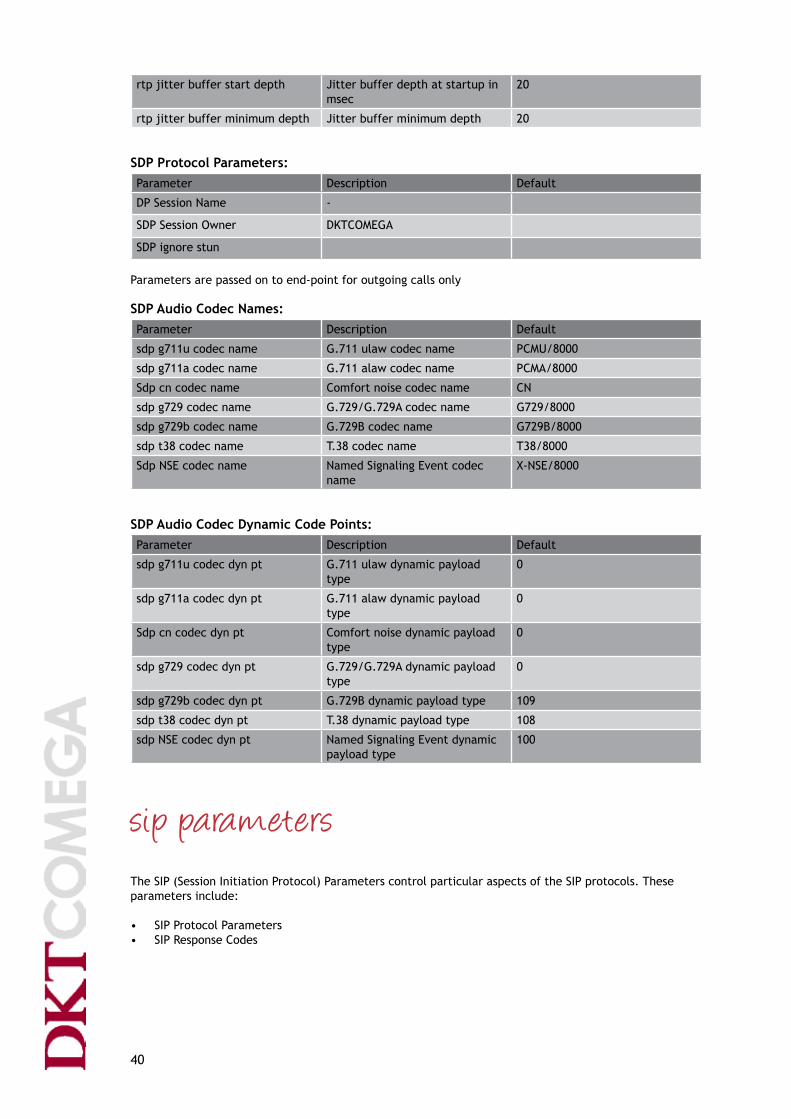
SDP Protocol Parameters: Parameter Description Default
DP Session Name -
SDP Session Owner DKTCOMEGA
SDP ignore stun
Parameters are passed on to end-point for outgoing calls only
SDP Audio Codec Names:Parameter Description Default
sdp g711u codec name G.711 ulaw codec name PCMU/8000
sdp g711a codec name G.711 alaw codec name PCMA/8000
Sdp cn codec name Comfort noise codec name CN
sdp g729 codec name G.729/G.729A codec name G729/8000
sdp g729b codec name G.729B codec name G729B/8000
sdp t38 codec name T.38 codec name T38/8000
Sdp NSE codec name Named Signaling Event codec name
X-NSE/8000
SDP Audio Codec Dynamic Code Points:Parameter Description Default
sdp g711u codec dyn pt G.711 ulaw dynamic payload type
0
sdp g711a codec dyn pt G.711 alaw dynamic payload type
0
Sdp cn codec dyn pt Comfort noise dynamic payload type
0
sdp g729 codec dyn pt G.729/G.729A dynamic payload type
0
sdp g729b codec dyn pt G.729B dynamic payload type 109
sdp t38 codec dyn pt T.38 dynamic payload type 108
sdp NSE codec dyn pt Named Signaling Event dynamic payload type
100
sip parameters The SIP (Session Initiation Protocol) Parameters control particular aspects of the SIP protocols. These parameters include:
• SIPProtocolParameters• SIPResponseCodes

41
• SIPDistinctiveRingNames• SIPProtocolTimers
SIP Protocol Parameters:Parameter Description Default
sip user agent User-Agent header for outbound responses if not empty
DKTCOMEGA 3.27
sip require user name Require username to match for incoming calls
Disabled
sip local port Local UDP port used for send-ing/ receiving SIP call control messages
5060
sip public external ip address ForceaspecificexternalIPaddress for SIP messages sent (disabled when 0.0.0.0)
0.0.0.0
sip public external sip port ForceaspecificexternalUDPport for SIP messages sent (disa-bled when 0)
0
sip tos value Type of service (TOS) value or DIFFServ DSFIELD used for SIP messages as a hexidecimal value
0x68
sip accept language string Specifiesthelanguageforuserviewable messages used in the SIP accept message
(empty)
sip send response to src port Respond to the sender’s IP address/UDP port used by SIP request message
Enabled
sip max forwards Maximum forward value 15
sip ringing retransmit Enables ringing invite retrans-mission
Enabled
sip use nat discovery Enable use of NAT discovery procedures to obtain an external IP address/UDP port mapping for SIP messages
Enabled
sip use received via info Use VIA header IP address/UDP port parameters in received messages as external IP address/UDP port
Disabled
sip nat keep alive enable Send periodic SIP messages to keep port mapping active
Disabled
sip nat keep alive interval Periodic interval in seconds for SIP keep alive messages
15
sip nat keep alive domain name Fullyqualifieddomainname(including an optional port num-ber) for the destination of SIP keep alive message (sends to the proxy server if empty)
(empty)
sip nat keep alive message Type of message to be sent as SIP keep alive: empty, notify or register
(empty)

42
sip prack enable Enables support for Provisional Response ACKnowledgement, PRACK(supportedfromfirmware05_05b6orlater)
Disabled
SIP Response Codes:Parameter Description Default
sip response code sit1 SIP response code which plays the SIT1 tone sequence
0
sip response code sit2 SIP response code which plays the SIT2 tone sequence
0
sip response code sit3 SIP response code which plays the SIT3 tone sequence
0
sip response code sit4 SIP response code which plays the SIT4 tone sequence
0
sip response code try backup SIP response code to use backup server
0
sip response code retry registra-tion
SIP response code to retry the registration
30
SIP Distinctive Ring Names:Parameter Description Default
sip distinctive ring names 1 Telephone event name to pro-duce distinctive ring pattern 1
Belcore-r1
sip distinctive ring names 2 Telephone event name to pro-duce distinctive ring pattern 2
Belcore-r2
sip distinctive ring names 3 Telephone event name to pro-duce distinctive ring pattern 3
Belcore-r3
sip distinctive ring names 4 Telephone event name to pro-duce distinctive ring pattern 4
Belcore-r4
sip distinctive ring names 5 Telephone event name to pro-duce distinctive ring pattern 5
Belcore-r5
sip distinctive ring names 6 Telephone event name to pro-duce distinctive ring pattern 6
Belcore-r6
sip distinctive ring names 7 Telephone event name to pro-duce distinctive ring pattern 7
Belcore-r7
sip distinctive ring names 8 Telephone event name to pro-duce distinctive ring pattern 8
Belcore-r8
SIP Protocol Timers:Parameter Description Default
sip timer invite expires Invite expiration in seconds 180
sip timer reinvite expires Re-invite expiration in seconds 180
sip timer registration min Registration period minimum in seconds
1
sip timer registration max Registration period maximum in seconds
7200
sip timer registration retry Registration expiration in sec-onds
30

43
sip timer no answer duration No answer duration in seconds 300
sip session time Session expiration in seconds 1800 SIP Server Configuration:Parameter Description Default
sip allow incoming subscription Disabled
sip subscribe authentication Disabled
sip incoming resubscribe interval Resubscribe interval in seconds 3600
sip allow incoming registration Disabled
sip register authentication Disabled
sip incoming reregister interval Reregister interval in seconds 3600
sip invite authentication Disabled
sip bye authentication Disabled
sip notify authentication Disabled
sip incoming auth user name (empty)
sip incoming auth realm (empty)
sip incoming auth password (empty)
ipbx parameters IPBX Parameters:
The parameters in the following three sections control the connection to the local phone (FXS) port on the ATA. This includes control of both the SLIC (Subscriber Line Interface Circuit) and SLAC (Subscriber LineAudioCircuit)thattogethermakeuptheFXSport.Thefirstsection,below,offersseparatecontrolfor voice and tone signals, of parameters including transmit and receive levels, and of DTMF tone charac-teristics.
Parameter Description Default
ipbx voice rx gain Additional voice receive gain in dB units
0
ipbx voice tx gain Additional voice transmit gain in dB units
0
ipbx tone gain Additional tonal signal gain in dB units
0
ipbx tone max Maximum tonal signal level in dBm
-12
dtmf low tone gain Low frequency group DTMF tone level in dBm
-9
dtmf high tone gain High frequency group DTMF tone level in dBm
-7
dtmf tone on time DTMF generation on time in msec 80
dtmf tone off time DTMF generation off time in msec
80

44
dtmf detect abcd DTMF detection enable for ABCD dual tone pairs
Enabled
dtmf generate abcd DTMF generation enable for ABCD dual tone pairs
Enabled
dtmf pad duration DTMF out-of-band on time in msec
100
dtmf wait duration DTMF out-of-band off time in msec
50
dtmf playout min duration DTMF out-of-band minimum on time in msec
100
Timers:Parameter Description Default
ipbx brief pause duration Time in 10 msec units before tone
50
ipbx initial dial duration Timeout in 10 msec units from off-hooktofirstdialeddigit
1500
ipbx warm line duration Timeout in 10 msec units from off-hooktofirstdialeddigitbefore warm dial
400
ipbx interdigit duration Timeout in 10 msec units be-tween digits after dial string al-ready matches a possible pattern
500
ipbx dialing duration Timeout in 10 msec units after each digit until next digit
1000
ipbx hangup disconnect duration Hangup disconnect duration in 10 msec units
85
ipbx hangup silence duration Hangup silence duration in 10 msec units
1000
ipbx pause wait duration DTMF dial string pause duration in 10 msec units
300
ipbx timeout tone duration Duration of busy in 10 msec units after aborted dialing or aborted answer (glare)
6000
ipbx timeout pause duration Pause in 10 msec units between busy and alert tone
100
ipbx timeout warning duration Duration of alerting tone in 10 msec units when off hook for too long
0
ipbx timeout hold duration Duration of time in 10 msec units before call holding tone
1000
ipbx timeout hold drop duration Duration of time in 10 msec units before dropping holding call
6000
ipbx no answer duration No answer duration in seconds 20
ipbx call back duration Callback duration in seconds 1800
ipbx call back retry duration Callback retry duration in sec-onds
30
ipbx call back ring wait duration Callback ring wait duration in seconds
1
ipbx message waiting refresh duration
Message waiting refresh duration in seconds
1800

45
ipbxhookflashmaximum Time in msec for maximum hookflash
900
ipbxhookflashminimum Time in msec for minimum hookflash
100
ipbxhookflashdelay Timeinmsectodelayhookflashaction in case of hangup
200
ipbx answer hangup delay Time in msec for answer side hangup delay
0
Other:Parameter Description Default
ipbx concurrent line count Number of concurrent line per-mitted
2
ipbx concurrent voip count Number of concurrent VoIP segments permitted including conferences
3
ipbx epoch clock limit Call progress, ringer and display synchronization period in sam-ples (16000 for two seconds and 48000 for six seconds)
16000
ipbx hook debounce Debounce test count for hook on/off transitions
10
ipbxhookflashenable A parameter added to disable hookflashprocessing
1
regionalization TheRegionalizationsettingsareusedtoconfiguretheATAforlocaloperatingconventions.Theseinclude:
• CallProgressTones• DefaultRingingPatterns• DistinctiveRingingPatterns• DistinctiveCallWaitingPatterns• LEDPatternsandPriority• VoiceandToneParameters• SLACConfiguration• CommandStrings
Call Progress Tones:Callprogresstonesarespecifiedbyalistofvaluesindicatingthenumberoftones,numberofon/offtransitions, frequency/signal level pairs and tone on/off times according to the following format:
no_of_tones, no_of_times, duration, {tone_element1_freq, tone_element1_db, tone_element2_freq, tone_element2_db, …}, {tone_on_time1, tone_off_time1, tone_on_time2, …}
•no_of_tones is the number of tone elements that are combined to form a tone. Each tone element

46
has an associated frequency and amplitude. Up to four tone elements can be combined – to form a chord, orplayedinsequence–asatune(seeno_of_times).Anegativeno_of_tonesindicatesthatthetoneswillbe synchronized to a two-second timer (relevant for multi-port ATAs only).
•no_of_times is the total of both on-to-off and off-to-on transitions in the tone pattern. If this value is positive, it produces a composite tone. If it is negative, the tones are played in sequence. Zero produces a continuous composite tone
• duration is the length of time in seconds that the call progress tone will be played. A value of zero means that the tone will be played until instructed otherwise.
•tone_elementX_freq and tone_elementX_db represent the frequency (Hz) and signal level (dB) of each tone. A negative frequency is used to modulate the prior tone components summed together. A negativedBmlevelcanbeoffsetbyipbx_tone_gain.
•tone_on_timeX and tone_off_timeX are interleaved Tone On and Tone Off durations in msec. A value of zero for a Tone On time indicates a continuous tone. A value of zero for a Tone Off time produces silence, while a negative value (-1) terminates the tone pattern, removing the silencing. (With silencing, the voice channel is blocked until the tone pattern is stopped.)
Allowed values for frequency are from 0 to 3000Hz. Allowed values for dB levels are from –1 to –40 dB. The maximum number of tones is 4. The maximum number of on-to-off and off-to-on times counted individually is 9.
For example, the default setting for initial dial tone is “{2, 0, 0, {350, -19, 440, -19}, {0}}”. “2” is the number of frequency/dB pairs, “350, -19” and “440, -19”. “0” is the number of on/off transitions in the tone pattern, which means that it is a constant tone. The second “0” indicates that thetonewillbeplayeduntilotherwiseinstructed.Thefirstpairoffrequency/dB“350, -19” means thatthefirsttoneisat350Hzwithalevelof-19dB.Thesecondpair“440, -19” means that the second toneisat440Hzwithalevelof-19dB.Thefinal“{0}” means that there are no on/off times and that the tone is constant.
Parameter Description Default
ipbx initial dial tone Initial composite dial tone pat-tern
{2, 0, 0, {350, -19, 440, -19}, {0}}
ipbx alternate dial tone Alternate dial tone pattern used with primary VoIP provider not available
{1, 0, 0, {400, -16}, {0}}
ipbx secondary dial tone Outside line composite dial tone pattern
{2, 0, 0, {420, -19, 520, -19}, {0}}
ipbx stuttered dial tone Stuttered composite dial tone pattern
{2, 7, 0, {350, -19, 440, -19}, {100, 110, 100, 110, 100, 110, 0}}
ipbx message wait dial tone Message waiting composite dial tone pattern
{2, 2, 0, {350, -19, 440, -19}, {160, 160}}
ipbx call forward dial tone Call forward composite dial tone pattern
{2, 3, 0, {350, -19, 440, -19}, {250, 400, 0}}
ipbx pre ringback tone Pre-ringback tone pattern se-quence
{4, -8, 0, {440, -16, 494, -19, 523, -19, 587, -19}, {340, 160, 340, 160, 340, 160, 340, 160}}
ipbx ringback tone Ringback composite tone pattern {2, 2, 0, {440, -19, 480, -19}, {2000, 4000}}
ipbx call waiting tone default Non-blocking call waiting single tone pattern
{1, 2, 0, {440, -16}, {300, 9700}}

47
ipbx station call waiting tone default
Non-blocking call waiting single tone pattern for station to sta-tion calls
{1, 2, 0, {440, -16}, {300, 9700}}
ipbx call holding tone Non-blocking call holding single tone pattern
{1, 4, 0, {1200, -16}, {100, 200, 100, -1}}
ipbx call hold disconnect tone Non-blocking call hold discon-nect single tone pattern
{1, 4, 0, {350, -16}, {50, 100, 50, -1}}
ipbx call disconnect tone Call disconnect tone pattern {2, 2, 0, {480, -19, 620, -19}, {500, 500}}
ipbx call conference tone Non-blocking conference call tone pattern
{1, 2, 0, {350, -16}, {100, 15000}}
ipbx busy tone Normal busy composite tone pattern
{2, 2, 0, {480, -19, 620, -19}, {500, 500}}
ipbx reorder tone Re-order (network/fast busy) composite tone pattern
{2, 2, 0, {480, -19, 620, -19}, {250, 250}}
ipbx off hook warning tone Off-hook warning composite tone pattern
{4, 2, 0, {1400, 11, 2050, 11, 2450, 11, 2600, 11}, {100, 100}}
ipbx sit1 tone Sit tone #1 tone sequence {3, -6, 0, {985, -16, 1428, -16, 1777, -16}, {330, 5, 330, 5, 330, 1000}}
ipbx sit2 tone Sit tone #2 tone sequence {3, -6, 0, {914, -16, 1371, -16, 1777, -16}, {330, 5, 330, 5, 330, 1000}}
ipbx sit3 tone Sit tone #3 tone sequence {3, -6, 0, {985, -16, 1428, -16, 1777, -16}, {380, 5, 380, 5, 380, 1000}}
ipbx sit4 tone Sit tone #4 tone sequence {3, -6, 0, {985, -16, 1428, -16, 1777, -16}, {380, 5, 380, 5, 380, 1000}}
ipbx prompt tone Prompt composite tone {2, 0, 0, {520, -19, 620, -19}, {0}}
ipbxconfirmtone Confirmationsingletone {1, 2, 0, {600, -16}, {400, 0}}
ipbx input error tone Input error composite tone pat-tern
{2, 2, 0, {480, -19, 620, -19}, {250, 250}}
ipbx number error tone Number error composite tone pattern
{2, 2, 0, {480, -19, 620, -19}, {250, 250}}
Standard Ringing Patterns:Ringpatternsarespecifiedbyalistofvaluesindicatingthefrequency,numberofon/offtransitionsandRing On/Ring Off times according to the following format: ring_frequency, no_of_times, duration, {ring_on_time1, ring_off_time1, ring_on_time2, ring_off_time2, …}
•ring_frequency specifiesthefrequencyoftheringingtoneinHzforsinusoidalandtrapezoidalring-

48
ing. This value is only used if the default ringer parameter slac_ring_frequency is zero.
•no_of_times is the total of both on and off transitions in the ring pattern. This can be zero for a con-tinuous ring signal (which may not be desirable and may exceed the rated power capacity of the ATA).
•duration is the length of time in seconds to ring. A value of zero means until instructed otherwise.
• ring_on_timeX and ring_off_timeX are interleaved Ring On and Ring Off durations in msec. A value of zero for a Ring On time indicates a continuous tone. A value of zero for a Ring Off time produces continuous silence. Possible values for frequency are between 0-60Hz. The maximum total of on and off times summed to-gether is 9.
Parameter Description Default
ipbx call ring default Default ring pattern {20, 2, 0, {2000, 4000}}
ipbx call station ring default Default station call ring pattern {20, 2, 0, {1000, 3000}}
ipbx call holding rering Call on hold reminder re-ring pattern
{20, 2, 0, {500, 0}}
ipbx call back ring Call back success ring pattern {20, 2, 0, {1500, 0}}
ipbx call back ring splash Call back in progress ring pattern {20, 2, 0, {700, 0}}
ipbx call forward ring splash Call forward reminder ring pat-tern
{20, 2, 0, {500, 0}}
ipbx message waiting ring splash1
Audible message waiting ring pattern
{20, 2, 0, {500, 0}}
Distinctive Ringing Patterns:The distinctive ring feature allows a different ring to be sent to the telephone as per the values of the Distinctive Ring parameters 1 - 8. Support for up to 8 distinctive rings is available to the user. The syntax for each of the distinctive ring parameters is the same as the default ring parameter where the frequen-cy, number of On/Off transitions, and the Ring On/Ring Off times can be set as desired.
Parameter Description Default
ipbx distinctive ring 1 Distinctive ring pattern #1 {20, 2, 0, {2000, 4000}}
ipbx distinctive ring 2 Distinctive ring pattern #2 {20, 4, 0, {1000, 1000, 1000, 3000}}
ipbx distinctive ring 3 Distinctive ring pattern #3 {20, 6, 0, {300, 200, 1000, 200, 300, 4000}}
ipbx distinctive ring 4 Distinctive ring pattern #4 {20, 4, 0, {800, 400, 800, 4000}}
ipbx distinctive ring 5 Distinctive ring pattern #5 {20, 4, 0, {400, 200, 400, 2000}}
ipbx distinctive ring 6 Distinctive ring pattern #6 {20, 2, 0, {1000, 3000}}
ipbx distinctive ring 7 Distinctive ring pattern #7 {20, 4, 0, {300, 200, 1500, 2000}}
ipbx distinctive ring 8 Distinctive ring pattern #8 {20, 4, 0, {800, 400, 800, 2000}}
Distinctive Call Waiting Patterns:A distinctive call waiting tone is played when an incoming call arrives while the phone is in use. Support for up to 8 distinctive call waiting tone patterns is available. The syntax for each of the distinctive call waiting tone parameters is the same as the default call waiting tone parameter where the number of tones, number of On/Off transitions, Frequency/Signal level pairs and the tone On/Off times can be set as desired.

49
Parameter Description Default
ipbx call waiting tone 1 Non-blocking call waiting #1 single tone pattern
{1, 2, 0, {440, -16}, {300, 9700}}
ipbx call waiting tone 2 Non-blocking call waiting #2 single tone pattern
{1, 6, 0, {440, -16}, {100, 20, 100, 20, 100, 9660}}
ipbx call waiting tone 3 Non-blocking call waiting #3 single tone pattern
{1, 4, 0, {440, -16}, {100, 100, 100, 9700}}
ipbx call waiting tone 4 Non-blocking call waiting #4 single tone pattern
{1, 6, 0, {440, -16}, {100, 100, 100, 100, 100, 9500}}
ipbx call waiting tone 5 Non-blocking call waiting #5 single tone pattern
{1, 2, 0, {620, -16}, {300, 9700}}
ipbx call waiting tone 6 blocking call waiting #6 single tone pattern
{1, 6, 0, {620, -16}, {100, 20, 100, 20, 100, 9660}}
ipbx call waiting tone 7 Non-blocking call waiting #7 single tone pattern
{1, 4, 0, {620, -16}, {100, 100, 100, 9700}}
ipbx call waiting tone 8 Non-blocking call waiting #8 single tone pattern
{1, 6, 0, {620, -16}, {100, 100, 100, 100, 100, 9500}}
SLAC Configuration:Parameter Description Default
slac port impedance Synthetic impedance matching network control for a choice of one in ten common world-wide configurations
600 ohm
slac port rx gain (GR) SLAC receive gain in dB units -3
slac port tx gain (GX) SLAC transmit gain in dB units 6
slac audio clamp slac caller id type 1 mode Caller ID type 1 (on-hook) mode (None, Belcore MDMF, SDMF, ETSI WINK, ETSI RING and DTMF)
Belcore MDMF
slac caller id type 2 mode Caller ID type 2 (off-hook) mode (None, Belcore MDMF, SDMF, ETSI WINK, ETSI RING and DTMF)
Belcore MDMF
slac message waiting mode Message waiting mode (None, Belcore VMWI, ETSI, DTMF)
Belcore VMWI
slac ring type Selects ring waveform type of sinusoidal or trapezoidal
sinusoidal
slac ring frequency Ringer frequency in Hz (zero to use ring pattern frequency specification)
slac ring transition Trapezoidal transition time in msec
15
slac ring amplitude Ringer voltage in volts 85

50
slac ring bias Ringer bias in volts 0
slac message waiting type Selects visual message waiting waveform type of sinusoidal or trapezoidal
Sinusoidal
slac message waiting frequency Visual message waiting frequen-cy in Hz
25
slac message waiting transition Trapezoidal transition time in msec
15
slac message waiting amplitude Visual message waiting voltage in volts
50
slac message waiting bias Visual message waiting bias in volts
0
slac dtmf caller id start code The parameters ‘slac dtmf caller id start code’ and ‘slac dtmf caller id end code’ allow you toconfigurethestartandendcodes respectively.
slac dtmf caller id end code The parameters ‘slac dtmf caller id start code’ and ‘slac dtmf caller id end code’ allow you toconfigurethestartandendcodes respectively.
slac dtmf caller id polarity reversal
DTMF polarity reversal as per ETSI EN 300 659-1: Subscriber line protocol over the local loop for display (and related) services ; Part 1 : On-hook data transmis-sion. The parameter ‘slac dtmf caller id polarity reversal’ allow you to enable to disable polarity reversal during DTMF caller ID transmission. This function will invert voltage when DTMF tones are transmitted on the analogue interface (Caller Id) before ring-ing.
Disabled
SLAC Command Strings:Parameter Description Default
slac initialization commands 100
slac impedance commands 1 SLAC commands to synthesize 600 ohm impedance
(many)
slac impedance commands 2 SLAC commands to synthesize 900 ohm impedance
(many)
slac impedance commands 3 SLAC commands to synthesize 600 ohm + 1.0uF impedance
(many)
slac impedance commands 4 SLAC commands to synthesize 900 ohm + 2.16uF impedance
(many)
slac impedance commands 5 SLAC commands to synthesize 270 ohm + 750 ohm || 150nF impedance
(many)

51
slac impedance commands 6 SLAC commands to synthesize 220 ohm + 820 ohm || 120nF impedance
(many)
slac impedance commands 7 SLAC commands to synthesize 220 ohm + 820 ohm || 115nF impedance
(many)
slac impedance commands 8 SLAC commands to synthesize 370 ohm + 620 ohm || 310nF impedance
(many)
slac impedance commands 9 SLAC commands to synthesize 200 ohm + 680 ohm || 100nF impedance
(many)
slac impedance commands 10 SLAC commands to synthesize 800 ohm + 50nF impedance
(many)
subscription servicesSubscriptionServicesconfiguretheATAforthespecificadvancedservicespermittedand/orsupported.These include:
• SubscriptionServices• PortConfiguration
Subscription Service Parameters:Parameter Description Default
ipbx call waiting service Enables customer use of call waiting service
Enabled
ipbx caller id inbound service Enables customer use of incom-ing caller ID service
Enabled
ipbx caller id outbound service Enables customer use of outgo-ing caller ID service (i.e. always send caller ID information)
Enabled
ipbx call waiting caller id service Enables customer use of incom-ing caller ID during call waiting service
Enabled
ipbx call back service Enables customer use of call back service
Enabled
ipbx call return service Enables customer use of call return service
Enabled
ipbx speed dial service Enables customer use of speed dial service
Enabled
ipbx do not disturb service Enables customer use of do not disturb service
Enabled
ipbx block anonymous service Enables customer use of anony-mous call block service
Enabled
ipbx call forward service Enables customer use of call forward service
Enabled

52
ipbx busy forward service Enables customer use of call forward when busy service
Enabled
ipbx no answer forward service Enables customer use of no an-swer call forward service
Enabled
ipbx priority forward service Enables customer use of priority call service
Enabled
ipbx distinctive ring service Enables customer use of distinc-tive ring service
Enabled
ipbx disturb accept service Enables customer use of do not disturb accept service
Enabled
ipbx blocked number service Enables customer use of blocked number service
Enabled
Ipbx outgoing block number service
Enables outgoing block service Enabled
ipbx forward last call service Enables customer use of forward to last caller service
Enabled
ipbx distinctive ring last call service
Enables customer use of distinc-tive ring for last caller service
Enabled
ipbx disturb accept last call service
Enables customer use of do not disturb accept last caller service
Enabled
ipbx block last call service Enables customer use of block last caller service
Enabled
ipbx three way calling service Enables customer use of three way calling service
Enabled
ipbx three way conference service3
Enables customer use of three way conference service
Enabled
ipbx attended transfer service Enables customer use of attend-ed call transfer service
Enabled
ipbx unattended transfer service Enables customer use of unat-tended call transfer service
Enabled
ipbx message waiting service Enables customer use of message waiting service
Enabled
ipbx visual message waiting service
Enables customer use of visual message waiting service. If enabled the ATA will send FSK data to the phone indicating the presence or non-presence of a message. The ATA supports the Belcore SDMF and Belcore MDMF standards of visual message waiting indication
Enabled
ipbx remote feature code ser-vice
Enables sending all features codes to remote service provider
Disabled
ipbx default feature code service Enables sending all unprocessed feature codes to remote service provider
Disabled
Port Configuration:Parameter Description Default
ipbx line 1 enable Enables use of physical line 1 Enabled
ipbx line 2 enable Enables use of physical line 2 Enabled

53
ipbx line 1 number Assigned local number for line 1 L1
ipbx line 2 number Assigned local number for line 2 L2
ipbx line 1 name Assigned name for line 1 (Empty)
ipbx line 2 name Assigned name for line 2 (Empty) 3 As far as conferencing goes, the ATA can handle two simultaneous media connections. If both ports are in use, local conferencing inside the ATA is not possible.
If three way conferencing is enabled:
Scenario 1 (while in call):
1. Hookflashputscurrentcallonhold.2. Dial and connect second call.3. Hookflashconferencesthecallstogether.4a.Hookflashhangsupthesecondcall.
or
4b. Hanging up will transfer the 2 remote calls together (attended transfer).
Scenario 2 (while in call):
1. Incoming call received (call waiting).2. Hookflashtoacceptcallwaitingcall.3. Hookflashtoswitchbacktofirstcall.4. Hookflashtoswitchbackandforthbetweencalls.
Scenario 3 (while in call and local processing of feature codes is enabled):
1. Hookflashputscurrentcallonhold.2. Dial *98 followed by a phone number.3. Current call will be transferred to number dialed in step 2 (blind transfer).
The difference between scenarios 1 and 2 is the direction of the second call. In scenario 1 the second call was an outgoing call from the ATA. In this case the ATA is able to conference the two calls together. In scenario 2 the second call was incoming to the ATA. In this case conferencing is not available. If three way conferencing is disabled the behavior is the same as scenario 2 regardless of whether the second call wasincomingornot(i.e.hookflashingwillswitchbetweenthetwoactivecalls).

54
Operating Mode:Parameter Description Default
ipbx mode ATA operating mode (ASS, SIHT, IHT, SIOT, IPBX)ASS (A Simple Service): The simplest mode passes all digits, as well as * and #, to the pattern matches for VOIP or PSTN calls. In this mode there is absolutely no feature codes, speed dialing or manual call routing.SIHT (Simple Internet Home Termination):This mode provides dialing priority for a VoIP call and al-most eliminates all special codes for access to other sta-tions. This is best used for a maximum of 2 to 4 stations. Themostsignificantsimplificationisforplacingacallon hold and picking it up. No transfer/pickup codes are needed. Picking up both lines conferences them togeth-er. A line may press * or # to get a new line to place their own call. Very limited feature sequences are needed.IHT (Internet Home Termination): This mode provides dialing priority for a VoIP call and requires special codes for access to other stations. This can be scaled from 2 to 8 stations (and possibly more by increasingthenumberofdigitsusedforstationidentifi-cation).SIOT(SmallInternetOfficeTermination):ThismodeisasimplifiedIBX/enhancedIHTIPBX (Internet Private Branch Exchange):This mode provides dialing priority for station-to-station calls and requires dialing 8 or 9 to place PSTN and VoIP calls. This can be scaled from 2 to 99 (or 999) stations withtheuseofmoredigitsforstationidentification.SIHT, value ‘1’
ipbx voip primary pro-vider unavailable
Dial tone to be generated when the primary provider is not available
Standard Dial Tone
ipbx voip no provider available
Dial tone to be generated when all VoIP providers are not available
Alternate Dial Tone
ipbx pstn not available Dial tone to be generated when no VoIP provider is avail-able and no PSTN dial tone is available
No Dial Tone
ipbx dial direct Direct dial processing mode (VoIP, PSTN, BOTH or DIRECT) BOTH
ipbx dial after 8 Processingmodeafteran8prefix(VoIP,PSTN,BOTHorDIRECT)
PSTN
ipbx dial after 9 Processingmodeaftera9prefix(VoIP,PSTN,BOTHorDIRECT)
VoIP
ipbx dial after pound 8 Processingmodeaftera#8prefix(VoIP,PSTN,BOTHorDIRECT)
BOTH
ipbx dial after pound 9 Processingmodeaftera#9prefix(VoIP,PSTN,BOTHorDIRECT)
BOTH
ipbx dial speed dial Processing mode for speed dial (VoIP, PSTN, BOTH or DIRECT)
VoIP

55
ipbx input pattern voip Pattern match for VoIP dialing [3469]11|*xx|**|1900r7x!| 976r4!|1800r7x|[^1]r6x|1r3x[^1]r6x|1010Se#e*p2r*x| 0Se#e*p2r*x
ipbx input pattern pstn Pattern match for PSTN dialing 911
ipbx hot line dialing Enables automatic hot-line dialing Disabled
ipbx warm line dialing Enables shorter duration timeout for warm line dialing Disabled
ipbx hotwarm dial string
Hot/warm dial string (empty)
ipbx polarity dialing Sets the SLAC line polarity during dialing (forward or reverse)
Forward
ipbx polarity dial done Sets the SLAC line polarity after dialing is done (forward or reverse)
Forward
ipbx polarity connect Sets the SLAC line polarity during connect (forward or reverse)
Forward
ipbx polarity an-swer
Sets the SLAC line polarity during answer (forward or reverse)
Forward
ipbx polarity idle Sets the SLAC line polarity during idle (forward or re-verse)
Forward
Ipbx party line enable Enables the two lines to be bridged with the use of hock flash
Disabled
VoIP Dial Pattern:The VoIP Dial Pattern and the PSTN Dial Pattern together determine how the ATA handles dial strings when someone dials a number from an attached phone. For units without an FXO port, the PSTN Dial Pattern is ignored. In a given location, there are generally only a few types of dialed numbers that need to be defined.Thereisdialingforlocalcalls,thereisdialingfordomestictollcalls,andthereisdialingforin-ternationaltollcalls.Inaddition,therearespecificshortstringsthataresetasideforemergencydialing,and there may be other special strings that invoke telephone features.
Bydefault,theATAisconfiguredtohandlenumberpatternsineverycountryintheworld.Formodelswith an FXO port, emergency calls are by default routed to the PSTN, and all other calls are routed via VoIP. You can use the Dial Patterns to change which calls are sent via VoIP, and which are sent to the PSTN. For example, you may want to send all local calls via the PSTN, because these may be free on yourPSTNline.YoumayalsowanttotailortheDialPatternstopreciselyreflecttheformatoftelephonenumbersinyourlocation.Forexample,thedefaultconfigurationrecognizesthatalocalnumbermaybefrom 5 to 10 digits long. If local numbers are always 8 digits, this means that the ATA will wait a few sec-ondsafterthe8thdigithasbeendialed,toseeifanydigitsfollow.Youcouldredefinethelocaldialstringalways to expect 8 digits, and to immediately send the number to the service provider once someone had dialed 8 digits.
Parameter Description
“|” separates different possible patterns
“r” repeatbyfollowinganumber(1-9),letter(a-zfor10to35times)or“*”,“+”or“.”tomean any number of times (255 times)
“.” repeat previous digit any number of times (0 to 255)

56
“+” repeat previous digit any number of times (0 to 255)
“x” match any numerical digit (0-9)
“~” matchanydigit(0-9,A-D,*,#)excludinganyspecifiedterminators
“!” disallows pattern
“$” indicatessecondarydialingtofollow-usedonlybyfixeddialstrings
“<:>” replace group to replace left digit(s) with right digit(s)
“[]” selection group of candidate digits
“[^]” exclusion group of digits
“[0-9]” selection range of candidate numerical digits
“[a-d]” selection range of candidate letter digits
“s” seize on string as only candidate if match to this point
“e” specify ending termination digit which follows (usually * or #)
“f” pause timeout causes failure instead of dial
“p” set digit pause to number of seconds which follow (1-9) for current pattern
“t” set digit timeout to default for current pattern
“-” human readable spacing which is ignored Interdigittimeout,orpause:Bydefault,thedeviceallowsfive(5)secondsbetweendialeddigits.Tochangethisdefault,youmustinsertthe“p”parameterbeforethepointinthematchstringthatyouwant this parameter to change. For example, if you would like a nine (9) second delay after each digit is pressed,thenyouwouldneedtoenter“p9”atthebeginningofthepatternmatchingstring.Similarly,ifyou would like a shorter timeout of three (3) seconds towards the end of a dial string, you would need to enter“p3”beforethelastentryinthepatternmatchingstring:…p3r*x.
Examples of dial strings:Each parameter in a pattern match string represents a single digit. The only exceptions are parameters that include a repeat operator. We will illustrate these features by examining the entries in the default VoIP dial string:
[346]11|*xx|**[1-9]e#r5xp3r*x|p8[1-9]e#r5xp3r*x|#[1-9]e#r5xp3r*x |1010Se#p2r*x|0Se#r5xp2r*x[3469]11
Recognize the sequences 311,411, 611 and 911, and send them to the service provider when com-plete. [3469]means“either3OR4OR6OR9”.Theentirestringmeans“either3OR4OR6OR9”followedby “11”.
*xx This string allows the ATA to recognize and forward feature codes to the service provider. However, note that by default, feature codes are handled locally, in the ATA. The ATA refers to this string only if the re-mote or default feature code parameters are enabled, or if Pass Through mode is enabled. In those cases, this string must be included in the pattern matching string, so that the ATA will forward feature codes to the service provider.

57
**[1-9]e#r5xp3r*x ThisstringpertainstoVoIPprovider“areacodes”.The“**”prefixisasignalfortheserviceproviderto forward this call to another VoIP service provider. The three digits following “**” constitute the VoIP provider“areacode.”Recognizeastringstartingwith“**”, and proceeding with any of the digits 1-9. “e#”defines“#”astheterminatingcharacter.Ifsomeonedials“#” at any point after the 1-9, the ATA sendsoutalldigitsdialedtothatpointtotheserviceprovider.Ifthepersondoesn’tdiala“#”,collectfivemoredigits(“’r5x”),switchfromthedefaultinter-digittimeoutoffive(5)secondstoashorterinter-digittimeoutofthree(3)seconds(“p3”),andcontinuecollectingdigitsuntilatimeoutoccurs(“r*x”).This string will be forwarded only if the ATA is in Pass Through Mode.
p8[1-9]e#r5xp3r*x This is the workhorse string of the default pattern for dialing. It matches dialing for VoIP calls, and for local dialing in most countries. It also matches dialing for domestic long distance dialing under the North Americandialplan.Thisstringisidenticaltotheprecedingstring,exceptforthefirsttwocharacters.Wheretheprecedingstringcallsforamatchtotheprefix“**”,thisstringredefinestheinterdigittimeout.Thisvaluehasbeenincreasedtoeight(8)seconds.Thistimeoutvaluepersistsuntilthefirstdigitplusfiveotherdigitshavebeencollected,atwhichtimethetimeoutvalueisreducedtothree(3)seconds. From that point onward, the ATA continues to collect digits until the user pauses three seconds, at which point, the ATA sends the dialed string to the service provider.
#[1-9]e#r5xp3r*x Thisstringisidenticaltotheprevioustwo,exceptforthefirstdigit.Thisstringsupportscaseswhereser-vice providers use strings that start with “#” for various special features or control purposes. This string is forwarded to the service provider only if the Mode is set to Pass Through.
1010Se#p2r*x This string is included to supported cases where North-American style dial-around dialing is available. The “S”meansthatifsomeonedials1010asthefirstfourdigitsofadialstring,thisistheonlystringtheATAshould match to from that point on. “e#” means that the user can indicate the completion of dialing at any time by entering “#”. “p2” means that after someone dials 1010, the timeout between subsequent digits is reduced to two (2) seconds. “r*x” means that the ATA will continue to collect dialed digits until there is a timeout.
0Se#r5xp2r*x This is the second workhorse string of the default pattern matching string. International calls in almost every country, and domestic long distance calls in most countries outside North America, all match this pattern. Any number that starts with zero (0) matches this string. The user may dial # at any time to indi-cate the number dialed is complete. After the user dials the sixth digit, the inter-digit timeout is reduced to two seconds. After that point, the ATA continues to collect digits until the user pauses two seconds. Then the ATA sends the dialed string to the service provider.
user conf igurationATA settings made by the user include:
• SpeedDials• CallForwarding• MessageWaiting• Timers• DistinctiveRinging• DoNotDisturb• CallBlocking• CallWaiting/CallerID
Speed Dial:TheSpeedDialListcanbemodifiedbythetelephoneorviathewebpages.Upto28numberscanbeentered into the Speed Dial List. Each number can be up to 40 digits in length.

58
Parameter Description Default
ipbx speed dial array *20 Speed dial number corresponding to *20
(empty)
(repeated)
ipbx speed dial array *39 Speed dial number corresponding to *39
(empty)
ipbx speed dial array #0 Speed dial number corresponding to #0
(empty)
(repeated)
ipbx speed dial array #7 Speed dial number corresponding to #7
(empty)
ipbx hot warm dial string Special number to be dialed when phone is picked up
(empty)
Call Forwarding:With Call Forward enabled, any call on this list will be forwarded to the number stored in the Call For-ward List (1-12). Up to thirty 40-digit numbers can be entered.
Parameter Description Default
ipbx call forward enable All call forward enable Disabled
ipbx busy forward enable Busy call forward enable Disabled
ipbx no answer forward enable No answer call forward enable Disabled
ipbx priority forward enable Priority call forward enable Disabled
ipbx call forward dial string Call forward destination (empty)
ipbx busy forward dial string Busy call forward destination (empty)
ipbx no answer forward dial string
No answer call forward destina-tion
(empty)
ipbx priority forward dial string Priority call forward destination (empty)
ipbx call forward list 1 Number to forward entry 1 (empty)
(repeated)
ipbx call forward list 30 Number to forward entry 30 (empty)
Distinctive Ringing:Parameter Description Default
ipbx distinctive ring enable Allows numbers on Distinctive Ring List to ring with a distinc-tive pattern
Enabled
ipbx distinctive ring list 1 Number for distinctive ringing entry 1
(empty)
(repeated)
ipbx distinctive ring list 30 Number for distinctive ringing entry 30
(empty)
Do Not Disturb:Parameter Description Default
ipbx do not disturb mode Enables Do Not Disturb Mode Disabled

59
ipbx disturb accept enable Enables only calls on the Disturb Accept List to ring
Disabled
ipbx disturb accept list 1 Number to accepted while in do not disturb state entry 1
(empty)
(Repeated)
Call Blocking:Parameter Description Default
ipbx block anonymous enable Blocks anonymous numbers Disabled
ipbx blocked number enable Enables blocking of calls from numbers in the Blocked Number List
Disabled
ipbx blocked number list 1 Numbers to block entry 1 (empty)
(repeated)
ipbx blocked number list 30 Numbers to block entry 30 (empty) Outgoing Call Blocking:Parameter Description Default
ipbx outgoing block enable Enables outgoing blocking of calls from numbers in the Blocked Number List
Disabled
ipbx outgoing block number list 1 Numbers to block entry 1 (empty)
(repeated)
ipbx outgoing block number list 30
Numbers to block entry 30 (empty)
Call Waiting/Caller ID:Parameter Description Default
ipbx call waiting enable Enables call waiting for all calls Enabled
ipbx caller id inbound enable Enables caller ID for inbound calls
Enabled
ipbx caller id outbound enable Enables caller ID for outbound calls
Enabled
ipbx caller id waiting enable Enables caller ID during call waiting
Disabled
Message Waiting:Parameter Description Default
ipbx message waiting Enables message waiting indica-tion
Off

60
feature code assignments (55 - 99) The IPBX calling features are assigned the ranges *55 to *89 and *92 to *99. The codes can be reassigned to better match common local conventions, but they must be given codes within the assigned ranges.
Parameter Description Default
ipbx fc call waiting enable Enable call waiting on all calls 55
ipbx fc call waiting disable Disable call waiting on all calls 56
ipbx fc call trace Call trace (reserved) 57
ipbx fc call waiting caller id enable Enable call waiting caller ID generation 58
ipbx fc call waiting caller id disable Disable call waiting caller ID generation 59
ipbx fc blocked number enable Enable call blocking feature 60
ipbx fc distinctive ring enable Enable distinctive ringing feature 61
ipbx fc caller id outbound disable Block caller ID on all outbound calls 62
ipbx fc priority forward enable Enable priority call forwarding feature 63
ipbx fc disturb accept enable Enable do not disturb accept call feature 64
ipbx fc caller id inbound enable Enable caller ID generation 65
ipbx fc busy number redial Busy number redial 66
ipbx fc caller id outbound enable once Unblock caller ID for one call 67
ipbx fc caller id outbound disable once Block caller ID for one call 68
ipbx fc caller redial Call the last caller 69
ipbx fc call waiting disable once Deactivate call waiting for current call 70
ipbx fc call waiting enable once Enable call waiting for current call 71
ipbx fc call forward enable Enable call forwarding to number which follows
72
ipbx fc call forward disable Cancel call forwarding of non-priority calls 73
ipbx fc one digit speed dial program Program speed dials 2-9 (20-39 imple-mented)
74
ipbx fc two digit speed dial program Program speed dials 20-49 (20-39 imple-mented)
75
ipbx fc block anonymous enable Block all anonymous calls 77
ipbx fc do not disturb enable Enter do not disturb state 78
ipbx fc do not disturb disable Exit do no disturb state 79
ipbx fc blocked number disable Cancel call lock - remove optional num-ber from blocked call list, or disable call blocking feature
80
ipbx fc distinctive ring disable Disable distinctive ringing 81
ipbx fc caller id outbound enable Unblock caller ID on all outbound calls 82
ipbx fc priority forward disable Cancel priority call forward 83
ipbx fc disturb accept disable Disable do not disturb accept call feature 84
ipbx fc caller id inbound disable Disable caller ID generation 85
ipbx fc busy number redial cancel Cancel busy redial 86
ipbx fc block anonymous disable Unblock anonymous calls 87
ipbxfchookflashsimulation 88
ipbx fc caller redial cancel Cancel calling last caller 89

61
ipbx fc no answer forward enable Call forward when no answer - number follows
92
ipbx fc no answer forward disable Cancel call forward when no answer 93
ipbx fc busy forward enable Call forward when busy - number follows 94
ipbx fc busy forward disable Cancel call forward when busy 95
ipbx outgoing block enable 96
ipbx outgoing block disable 97
ipbx fc unattended transfer 98
built-in wif i (for 79615 and 79616)Important:TheWifiAccessPointusestheLANport1asinterface,soallCPEswitchrelatedsettingsmadeforLANport 1 will be applicable to this interface. 79615 and 79616 do not have LAN port 1 available for other servicesthanwifi.
tftp based provisioningTheWifiAccessPointwillgetitsconfigurationviaaTFTPrequestinitiatedbytheCPE,whenthemoduleis present and enabled.
ThemoduleisenabledusingthefollowingcommandintheCPEconfigurationscript.
enable_wifi <host-wifi-setup-filename> [-t optional-TFTP-server-IP] [-p option-alpassword] [-w optional-WiFi-IP-address]
# The default password for the admin user is “admin”. If the password is changed, this new password may be supplied as the second parameter on the com-mand line. The default IP address of the wifi module is 192.168.1.250. If this is changed, then both the password and the correct IP address must be supplied on the command line. The default TFTP server is the same as used for the CPE configuration file.
system parameters ConfigurationoftheWifiAccessPointisdonewiththeuseofaconfigurationfile,includingthefollowingparameters,pleaserefertoAppendix2–Wificonfigurationfilefordetails.
Parameter Description Default
Default Do not touch -
WebInit Do not touch 1

62
HostName Wifihostname DKTCOMEGA
Login Administratorconfigurationaccessname,Pleaseconsult DKTCOMEGA for user name and pass-word
*********
Password Administrator password, Please consult DKTCO-MEGA for user name and password
*********
OperationMode WifiOperationModeThefollowingmodescanbeconfigured- Access Point (0)- Router (1)- AP Client (2)
0
Platform WifiModulePlatform,chipvendor RT3050
wanConnectionMode WAN Connection Type DHCP
wan_ipaddr Applicable to Router Operation Mode, WAN IP address
192.168.2.1
wan_netmask applicable to Router Operation Mode, IP Subnet mask
255.255.255.0
wan_gateway applicable to Router Operation Mode, IP Address of the WAN Gateway
192.168.2.254
wan_primary_dns applicable to Router Operation Mode, DNS Server, primary
168.95.1.1
wan_secondary_dns applicable to Router Operation Mode, DNS Server, secondary
168.95.192.1
wan_pppoe_user applicable to Router Operation Mode, PPPoE Username
pppoe_user
wan_pppoe_pass applicable to Router Operation Mode, PPPoW password
pppoe_passwd
wan_l2tp_server applicable to Router Operation Mode, Server IP Address
l2tp_server
wan_l2tp_user applicable to Router Operation Mode, Username l2tp_user
wan_l2tp_pass applicable to Router Operation Mode, Password l2tp_passwd
wan_l2tp_mode applicable to Router Operation Mode, Mode of Operation
0
wan_l2tp_ip applicable to Router Operation Mode, IP Address oftheWifi
192.168.2.1
wan_l2tp_netmask applicable to Router Operation Mode, Subnet maskoftheWifi
255.255.255.0
wan_l2tp_gateway applicable to Router Operation Mode, IP Address of the Gateway
192.168.2.254
wan_pptp_server applicable to Router Operation Mode, Point-to-point tunneling protocol, Server IP Address
pptp_server
wan_pptp_user applicable to Router Operation Mode, Point-to-point tunneling protocol, Username
pptp_user
wan_pptp_pass applicable to Router Operation Mode, Point-to-point tunneling protocol, Password
pptp_passwd
wan_pptp_mode applicable to Router Operation Mode, Point-to-point tunneling protocol, Mode of Operation
0

63
wan_pptp_ip applicable to Router Operation Mode, Point-to-pointtunnelingprotocol,IPAddressoftheWifi
192.168.2.1
wan_pptp_netmask applicable to Router Operation Mode, Point-to-point tunneling protocol, Subnet mask of the Wifi
255.255.255.0
wan_pptp_gateway applicable to Router Operation Mode, Point-to-point tunneling protocol, IP Address of the Gateway
192.168.2.254
lan_ipaddr LANIPAddressoftheWifi 192.168.1.250
lan_netmask SubnetmaskoftheWifi 255.255.255.0
dhcpEnabled DHCP Server functionality, Enable or Disable. ClientsconnectedtotheWifiwillgettheirIPAddressedbytheWifi.
0 (Disable)
dhcpStart Applicable to DHCP Enable, Start IP Address in the range
192.168.1.100
dhcpEnd Applicable to DHCP Enable, Stop IP Address of the rante
192.168.1.200
dhcpMask Applicable to DHCP Enable, Subnet mask 255.255.255.0
dhcpPriDns Applicable to DHCP Enable, Primary DNS Server IP Address
168.95.1.1
dhcpSecDns Applicable to DHCP Enable, Secondary DNS Server IP Address
168.95.192.1
dhcpGateway Applicable to DHCP Enable, IP Address of the Gateway
192.168.1.250
dhcpLease Applicable to DHCP Enable, this is the DHCP lease time. When it is short, the issued IP ad-dress to DHCP clients will be updated frequent-ly. It is recommended to keep default setting except for another purpose
86400 (24 hrs)
stpEnabled Spanning Tree 0
lltdEnabled Link Layer Topology Discovery, Enable or Disable 0
igmpEnabled IGMP functionality, Enable or Disable 0
natEnabled NAT functionality, Enable or Disable 1
IPPortFilterEnable IPbasedportfiltering,EnableorDisable 0
IPPortFilterRules IPbasedportfiltering,Rules -
PortForwardEnable Port Forwarding, Enable or Disable 0
PortForwardRules Port Forwarding, Rules -
MacFilterEnable MAC Filtering, Enable or Disable -
MacFilterRules MAC Filtering, Rules -
DefaultFirewallPolicy 1
DMZEnable De-Militarized Zone, Enable or Disable 0
DMZIPAddress Input the IP Address of the computer that you want to expose to Internet.
-
TZ -
NTPServerIP IP Address of the NTP Server -
NTPSync -

64
DDNSProvider -
DDNS -
DDNSAccount -
DDNSPassword -
BssidNum 4
SSID1 This device supports multiple SSID. Input the multipleSSID1,2,3inthefieldtoenablethefunction.WiththefieldofNetworkName(SSID), the device supports maximum 4 SSIDs.
DKTCOMEGA1
WirelessMode 9
TxRate 0;0;0;0
Channel 6
BasicRate 15
BeaconPeriod Beacons are the packets sending by Access point to synchronize the wireless network. The beacon interval is the time interval between beacons sending by this unit in AP or AP+WDS mode. The default and recommendedUser’s Guide 29beacon interval is 100 milliseconds
100
DtimPeriod ThisistheDeliveryTrafficIndicationMap.Itis used to alert the clients that multicast and broadcast packets buffer at the AP will be transmitted immediately after the transmission of this beacon frame. You can change the value from 1 to 255. The AP will check the buffer data according to this value. For example, selecting “1”meanstocheckthebufferdataateverybeacon.
1
TxPower 100
RxAckTimeout The Acknowledgement Timeout means from re-mote to local data transmission, one parameter to control both acknowledging action to guar-anty those packets have already be received. Usually, for short distance, keep default setting is proposed. If there is long distance applica-tion, have minor increased with this parameter will be proposed.
32
DisableOLBC 0
BGProtection Default: Auto. You can select the other options including On and Off. The B/G protection tech-nology is CTS-To-Self. It will try to reserve the throughput for 11bg clients association.
0
TxAntenna -
RxAntenna -
TxPreamble 0

65
RTSThreshold The RTS threshold determines the packet size at which the radio issues a request to send (RTS) before sending the packet. A low RTS Thresh-old setting can be useful in areas where many client devices are associating with the device, or in areas where the clients are far apart and can detect only the device and not each other. You can enter a setting ranging from 0 to 2347 bytes.
2347
FragThreshold The fragmentation threshold determines the size at which packets are fragmented (sent as several pieces instead of as one block). Use a low setting in areas where communication is poor or where there is a great deal of radio interference. This function will help you to improve the network performance.
2346
TxBurst The device will try to send a serial of packages with single ACK reply from the clients. Enable this function to apply it.
1
PktAggregate 1
TurboRate 0
StaLimitationEnable 0
StaLimitationNum 0
WmmCapable Choose“Enable”toenableWMM(Wi-FiMulti-media) function.
1;1;1;1
APAifsn 3;7;1;1
APCwmin 4;4;3;2
APCwmax 6;10;4;3
APTxop 0;0;94;47
APACM 0;0;0;0
BSSAifsn 3;7;2;2
BSSCwmin 4;4;3;2
BSSCwmax 10;10;4;3
BSSTxop 0;0;94;47
BSSACM 0;0;0;0
AckPolicy 0;0;0;0
APSDCapable Choose“Enable”toenableAPSD(AutomaticPower-Save Delivery) function.
0
DLSCapable 0
NoForwarding 0;0;0;0
NoForwardingBTNBSSID 0
HideSSID 0;0;0;0
ShortSlot 1
AutoChannelSelect=0 0
SecurityMode OPEN, SHARED, WEPAUTO, WPA RADIUS, WPA-PSK, WPA2 RADIUS, WPA2-PSK, WPA/WPA2 PSK, WPA/WPA2 RADIUS, 802.1X.
0

66
VLANEnable VLAN Support, Enable or Disable 0
VLANName VLAN name -
VLANID VLAN VID 0
VLANPriority VLAN priority 0
WscConfMode 0
WscConfStatus It shows the current status of the WPS process. 2
WscAKMP 1
WscConfigured ItindicatedwhethertheWPSisconfigured. 1
WscModeOption 0
WscActionIndex 9
WscPinCode Input the 8-digits PIN of client. -
WscRegResult 1
WscUseUPnP 1
WscUseUFD 0
WscSSID DKTCOMEGAAP
WscKeyMGMT WPA-EAP
WscConfigMethod 138
WscAuthType 1
WscEncrypType 1
WscNewKey Scaptest
IEEE8021X 0;0;0;0
IEEE80211H 0
CSPeriod 6
PreAuth 0;0;0;0
AuthMode WPAPSK;OPEN;OPEN;OPEN
EncrypType TKIP;NONE;NONE;NONE
RekeyInterval 3600
RekeyMethod DISABLE
PMKCachePeriod 10
WPAPSK1 WPA/WPA2-PSK Pass Phrase (8-64 characters). Key 2
56655153
DefaultKeyID 2;1;1;1
Key1Type 0;0;0;0
Key1Str1 -
Key2Type 0;0;0;0
Key2Str1 -
Key3Type 0;0;0;0
Key3Str1 -
Key4Type 0;0;0;0
Key4Str1 -
HSCounter 0
HT_HTC Applicable to HT Physical Mode 1

67
HT_RDG Applicable to HT Physical Mode, Reverse Direc-tion Grant (RDG). This is the 11n performance parameter. Enable it if needed.
1
HT_LinkAdapt Applicable to HT Physical Mode 0
HT_OpMode Applicable to HT Physical Mode 0
HT_MpduDensity Applicable to HT Physical Mode 5
HT_EXTCHA Applicable to HT Physical Mode 1
HT_BW Applicable to HT Physical Mode 1
HT_AutoBA Applicable to HT Physical Mode, Auto Block ACK.It is another aggregation technique which prevents sending ACK in the communication to increase the throughput. If this option is enabled, the device will activate this function when transmitting massive data.
1
HT_BADecline Applicable to HT Physical Mode, Decline BA Request, Enable this option to decline the Block ACK request addressed by the other devices.
0
HT_AMSDU Applicable to HT Physical Mode, Aggregation MSDU (A-MSDU). The multiple HT packets can be transmitted with single ACK reply packet. Enable it to apply this function and reduce the network congestion.
0
HT_BAWinSize Applicable to HT Physical Mode 64
HT_GI Applicable to HT Physical Mode 1
HT_STBC Applicable to HT Physical Mode 1
HT_MCS Applicable to HT Physical Mode 33;33;33;33
HT_PROTECT Applicable to HT Physical Mode 1
HT_MIMOPS Applicable to HT Physical Mode 3
HT_40MHZ_INTOLERANT Applicable to HT Physical Mode 0
HT_TxStream Applicable to HT Physical Mode 2
HT_RxStream Applicable to HT Physical Mode 2
NintendoCapable 0
AccessPolicy0 0
AccessControlList0 -
AccessPolicy1 0
AccessControlList1 -
AccessPolicy2 0
AccessControlList2 -
AccessPolicy3 0
AccessControlList3 -
WdsEnable Thisdevicesupports“AccessPoint”,“APallowsWDS”,“Bridge”and“Repeater”.Whenselect-ing“Bridge”,thisdeviceprovidesWDSconnec-tion only and doesn’t provide radio to the WLAN stations (clients). To provide both AP and WDS connections,select“Repeater”.
0

68
WdsPhyMode There are four modes including “CCK, OFDM, HTMIX,andGreenfield”.Selectoneaccordingthe WDS devices. The CCK is for pure 802.11b WDS network. OFDM is for pure 802.11g WDS network. HTMIX is for 802.11 g/n WDS network. Greenfieldisforpure802.11nWDSnetwork.
WdsEncrypType There are 4 types to support, NONE,WEP,TKIP,AES
NONE
WdsList -
WdsKey Please input the key for encryption -
WirelessEvent 0
RADIUS_Server Input the IP Address of the Radius server 0;0;0;0
RADIUS_Port Input the port of the Radius server. The default port is 1812.
1812;1812;1812;1812
RADIUS_Key Authentication Key DKTCOMEGA;DKTCOMEGA;DKTCOMEGA;DKTCOMEGA
RADIUS_Acct_Server -
RADIUS_Acct_Port 1813
RADIUS_Acct_Key -
session_timeout_interval maximum idle time for this connection 0
idle_timeout_interval 0
staWirelessMode 9
RemoteManagement Remote management (via WAN): you can select “Deny”or“Allow”todecidewhethertheWANof the device can be accessed. If it isn’t acces-sible, then you can’t open the web page from WAN.
1
WAN_MAC_ADDR MAC Address of the WAN interface
RFICType 5
TXPath 5
RXPath 1
SSID2 This device supports multiple SSID. Input the multipleSSID1,2,3inthefieldtoenablethefunction.WiththefieldofNetworkName(SSID), the device supports maximum 4 SSIDs.
DKTCOMEGA2
SSID3 This device supports multiple SSID. Input the multipleSSID1,2,3inthefieldtoenablethefunction.WiththefieldofNetworkName(SSID), the device supports maximum 4 SSIDs.
DKTCOMEGA3
SSID4 This device supports multiple SSID. Input the multipleSSID1,2,3inthefieldtoenablethefunction.WiththefieldofNetworkName(SSID), the device supports maximum 4 SSIDs.
DKTCOMEGA4
WPAPSK2 WPA/WPA2-PSK Pass Phrase (8-64 characters). Key 2
12345678
Key1Str2 -
Key2Str2 -
Key3Str2 -
Key4Str2 -
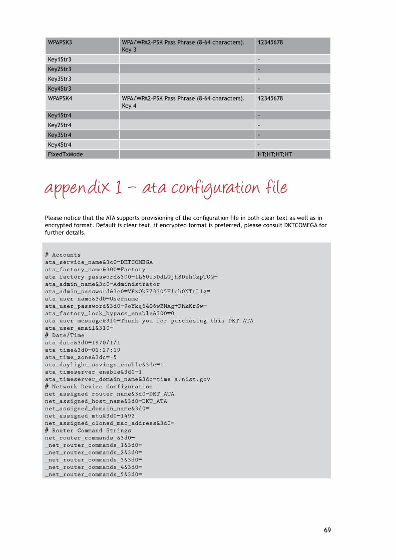
69
WPAPSK3 WPA/WPA2-PSK Pass Phrase (8-64 characters). Key 3
12345678
Key1Str3 -
Key2Str3 -
Key3Str3 -
Key4Str3 -
WPAPSK4 WPA/WPA2-PSK Pass Phrase (8-64 characters). Key 4
12345678
Key1Str4 -
Key2Str4 -
Key3Str4 -
Key4Str4 -
FixedTxMode HT;HT;HT;HT
appendix 1 – ata conf iguration f ilePleasenoticethattheATAsupportsprovisioningoftheconfigurationfileinbothcleartextaswellasinencrypted format. Default is clear text, if encrypted format is preferred, please consult DKTCOMEGA for further details.
# Accountsata_service_name&3c0=DKTCOMEGAata_factory_name&300=Factoryata_factory_password&300=1L60U5DdLQjh8DehGxpTCQ=ata_admin_name&3c0=Administratorata_admin_password&3c0=VPxOk773305H+qh0NTnL1g=ata_user_name&3d0=Usernameata_user_password&3d0=9oYkq64Q6wBNAg+FhkKrSw=ata_factory_lock_bypass_enable&300=0ata_user_message&3f0=Thank you for purchasing this DKT ATAata_user_email&310=# Date/Timeata_date&3d0=1970/1/1ata_time&3d0=01:27:19ata_time_zone&3dc=-5ata_daylight_savings_enable&3dc=1ata_timeserver_enable&3d0=1ata_timeserver_domain_name&3dc=time-a.nist.gov# Network Device Configurationnet_assigned_router_name&3d0=DKT_ATAnet_assigned_host_name&3d0=DKT_ATAnet_assigned_domain_name&3d0=net_assigned_mtu&3d0=1492net_assigned_cloned_mac_address&3d0=# Router Command Stringsnet_router_commands_&3d0=_net_router_commands_1&3d0=_net_router_commands_2&3d0=_net_router_commands_3&3d0=_net_router_commands_4&3d0=_net_router_commands_5&3d0=

70
_net_router_commands_6&3d0=_net_router_commands_7&3d0=_net_router_commands_8&3d0=_net_router_commands_9&3d0=_net_router_commands_10&3d0=# Static Network Configurationnet_static_config_enable&3dc=0net_static_ip_address&3dc=0.0.0.0net_static_netmask&3dc=255.255.255.0net_static_gateway_address&3dc=0.0.0.0# DNS Configurationnet_dns_primary_address&3dc=0.0.0.0net_dns_secondary_address&3dc=0.0.0.0net_dns_parallel_search_mode&3d0=0# Dynamic Network Configurationnet_isp_dhcp_enable&3dc=1net_isp_pppoe_enable&3dc=0net_isp_user_name&3dc=net_isp_password&3dc=net_isp_dhcp_discover_duration&3d0=1net_isp_connect_on_demand_enable&3d0=0net_isp_connect_on_demand_interval&3d0=0net_isp_keep_alive_enable&3d0=0net_isp_keep_alive_interval&3d0=0net_isp_reconnect_on_link_loss&3d0=0net_isp_save_as_assigned&3f0=0# Remote Configuration Accessata_web_external_server_enable&3f0=1ata_web_internal_server_enable&3f0=1ata_web_server_port&3f0=0ata_web_server_language&3f0=0ata_telnet_server_enable&3f0=1ata_telnet_server_port&3f0=0ata_ftp_server_enable&3f0=1ata_ftp_server_port&3f0=0# NAT Transversal Parametersnat_stun_enable&3dc=1nat_stun_dns_lookup_mode&3d0=0nat_stun_server_domain_name&3dc=nat_stun_symmetric_deterministic_enable&3dc=1nat_turn_enable&3dc=0nat_turn_server_domain_name&3dc=nat_ice_enable&3f0=0# Update Parametersata_local_update_enable&13f0=0ata_local_update_domain_name&3f0=ata_dhcp_update_enable&3c0=1ata_update_domain_name&3fc=update.dktcomega.com:5070ata_recovery_domain_name&300=recovery.dktcomega.com:5070ata_finalize_domain_name&300=finalize.dktcomega.com:5070ata_email_domain_name&300=email.dktcomega.comata_options_domain_name&300=options.dktcomega.comata_lcr_domain_name&300=lcr.dktcomega.comata_configuration_update_enable&3c0=0ata_configuration_update_on_reset&3c0=0ata_configuration_update_from_sip&3c0=0ata_configuration_recover_enable&3c0=0ata_configuration_request_message&3c0=ata_configuration_success_message&3c0=Configuration update successfulata_configuration_failed_message&3c0=Configuration update failed

71
ata_configuration_update_periodic_delay&3c0=3600ata_configuration_update_random_delay&3c0=240ata_configuration_update_error_retry_delay&3c0=120ata_firmware_update_enable&3fc=0ata_firmware_update_on_reset&3c0=0ata_firmware_recovery_enable&3c0=0ata_firmware_request_message&3c0=ata_firmware_success_message&3c0=Firmware update successfulata_firmware_failed_message&3c0=Firmware update failedata_firmware_update_periodic_delay&3c0=86400ata_firmware_update_random_delay&3c0=240ata_firmware_update_error_retry_delay&3c0=120# ATA Maintenanceata_help_url&3c0=help.htmlata_logo_url&3c0=atalogo.jpgnet_syslog_enable&3c0=0net_syslog_server&3c0=net_debug_enable&3c0=0net_debug_server&3c0=net_debug_level_ata&3c0=7net_debug_level_sip&3c0=307net_debug_level_mgcp&3c0=307net_debug_level_net&3c0=7net_debug_level_omc&3c0=7net_debug_level_pmp&3c0=7# System Identificationata_copyright_notice&12a0=ATA Ver 5.04 (C) 1994-2008 DKTCOMEGA A/Sata_manufacturer&12a0=DKTata_model_number&12a0=ATA2ata_serial_number&12a0=3108ata_hardware_revision&12a0=000ata_boot_rom_revision&12a0=5.03ata_firmware_revision&12a0=5.04ata_configuration_revision&12a0=1.00.00ata_processor_chip_id&1200=ata_processor_die_id&1200=net_hardware_mac_address&12a0= net_unique_device_id&12a0= #ata_processor_chip_id&1200=bf527#ata_processor_die_id&1200=b0c090220b980c3989db2276c89d0000#net_hardware_mac_address&12a0=00:50:c2:32:71:6c#net_unique_device_id&12a0=DKT_ATA_0050c232716cata_system_info_1&300=ata_system_info_2&300=ata_system_info_3&300=ata_system_info_4&300=ata_system_info_5&300=# VoIP Account 1 Informationvoip_provider_1&3dc=_voip_provider_1.provider_name&3fc=_voip_provider_1.provider_type&3fc=1_voip_provider_1.distinctive_ring_type&3fc=1_voip_provider_1.dialing_prefix&3dc=_voip_provider_1.preferred_audio_codecs&23fc=_voip_provider_1.incoming_mode&3d0=0_voip_provider_1.group_line_1_enable&3d0=1_voip_provider_1.group_line_2_enable&3d0=1_voip_provider_1.use_outbound_proxy&3d0=0_voip_provider_1.dns_lookup_mode&3d0=0_voip_provider_1.display_name&23fc=

72
_voip_provider_1.user_name&3fc=_voip_provider_1.domain_name&3fc=_voip_provider_1.auth_user_name&23fc=_voip_provider_1.auth_domain_name&23fc=_voip_provider_1.auth_user_password&3fc=_voip_provider_1.proxy_domain_name&3fc=_voip_provider_1.register_domain_name&3fc=_voip_provider_1.reregister_interval&23fc=120_voip_provider_1.subscription_domain_name&23fc=_voip_provider_1.resubscribe_interval&23fc=0# VoIP Account 2 Informationvoip_provider_2&3dc=_voip_provider_2.provider_name&3fc=_voip_provider_2.provider_type&3fc=0_voip_provider_2.distinctive_ring_type&3fc=0_voip_provider_2.dialing_prefix&3dc=_voip_provider_2.preferred_audio_codecs&23fc=_voip_provider_2.incoming_mode&3d0=0_voip_provider_2.group_line_1_enable&3d0=1_voip_provider_2.group_line_2_enable&3d0=1_voip_provider_2.use_outbound_proxy&3d0=0_voip_provider_2.dns_lookup_mode&3d0=0_voip_provider_2.display_name&23fc=_voip_provider_2.user_name&3fc=_voip_provider_2.domain_name&3fc=_voip_provider_2.auth_user_name&23fc=_voip_provider_2.auth_domain_name&23fc=_voip_provider_2.auth_user_password&3fc=_voip_provider_2.proxy_domain_name&3fc=_voip_provider_2.register_domain_name&3fc=_voip_provider_2.reregister_interval&23fc=120_voip_provider_2.subscription_domain_name&23fc=_voip_provider_2.resubscribe_interval&23fc=120# VoIP Account 3 Informationvoip_provider_3&3dc=_voip_provider_3.provider_name&3fc=_voip_provider_3.provider_type&3fc=0_voip_provider_3.distinctive_ring_type&3fc=0_voip_provider_3.dialing_prefix&3dc=_voip_provider_3.preferred_audio_codecs&23fc=_voip_provider_3.incoming_mode&3d0=0_voip_provider_3.group_line_1_enable&3d0=1_voip_provider_3.group_line_2_enable&3d0=1_voip_provider_3.use_outbound_proxy&3d0=0_voip_provider_3.dns_lookup_mode&3d0=0_voip_provider_3.display_name&23fc=_voip_provider_3.user_name&3fc=_voip_provider_3.domain_name&3fc=_voip_provider_3.auth_user_name&23fc=_voip_provider_3.auth_domain_name&23fc=_voip_provider_3.auth_user_password&3fc=_voip_provider_3.proxy_domain_name&3fc=_voip_provider_3.register_domain_name&3fc=_voip_provider_3.reregister_interval&23fc=120_voip_provider_3.subscription_domain_name&23fc=_voip_provider_3.resubscribe_interval&23fc=120# VoIP Account 4 Informationvoip_provider_4&3dc=_voip_provider_4.provider_name&3fc=_voip_provider_4.provider_type&3fc=0

73
_voip_provider_4.distinctive_ring_type&3fc=0_voip_provider_4.dialing_prefix&3dc=_voip_provider_4.preferred_audio_codecs&23fc=_voip_provider_4.incoming_mode&3d0=0_voip_provider_4.group_line_1_enable&3d0=1_voip_provider_4.group_line_2_enable&3d0=1_voip_provider_4.use_outbound_proxy&3d0=0_voip_provider_4.dns_lookup_mode&3d0=0_voip_provider_4.display_name&23fc=_voip_provider_4.user_name&3fc=_voip_provider_4.domain_name&3fc=_voip_provider_4.auth_user_name&23fc=_voip_provider_4.auth_domain_name&23fc=_voip_provider_4.auth_user_password&3fc=_voip_provider_4.proxy_domain_name&3fc=_voip_provider_4.register_domain_name&3fc=_voip_provider_4.reregister_interval&23fc=120_voip_provider_4.subscription_domain_name&23fc=_voip_provider_4.resubscribe_interval&23fc=120# VoIP Provider Defaultsvoip_default_display_name&3e0=voip_default_user_name&3e0=voip_provider_default_line_1&3c0=1voip_provider_alternate_line_1&3c0=0voip_provider_default_line_2&3c0=1voip_provider_alternate_line_2&3c0=0# Audio Settingsvoip_preferred_audio_codecs&3e0=18 0 8 109 voip_silence_suppression_enable&3e0=0voip_echo_canceller_enable&3e0=1voip_echo_canceller_mode&3e0=2voip_echo_canceller_tail_length&3e0=16voip_fax_processing_mode&3e0=0voip_dtmf_transmit_method&3e0=0# RTP Protocol Parametersrtp_port_minimum&3e0=1234rtp_port_maximum&3e0=65535rtp_public_external_ip_address&3e0=0.0.0.0rtp_public_external_port_min&3e0=0rtp_tos_value&3e0=68rtp_packet_duration&3e0=30rtp_stream_duration&3e0=20rtp_session_timeout_interval&3e0=900rtp_jitter_buffer_start_depth&3e0=20rtp_jitter_buffer_minimum_depth&3e0=20# SDP Protocol Parameterssdp_session_name&3e0=-sdp_session_owner&3e0=DKTsdp_ignore_stun&3e0=1# SDP Audio Codec Namessdp_g711u_codec_name&3e0=PCMU/8000sdp_g711a_codec_name&3e0=PCMA/8000sdp_cn_codec_name&3e0=CNsdp_g729_codec_name&3e0=G729/8000sdp_g729b_codec_name&3e0=G729B/8000sdp_t38_codec_name&3e0=T38/8000sdp_NSE_codec_name&3e0=X-NSE/8000sdp_AVT_codec_name&3e0=telephone-event/8000# SDP Audio Codec Dynamic Code Pointssdp_g711u_codec_dyn_pt&3e0=0

74
sdp_g711a_codec_dyn_pt&3e0=0sdp_cn_codec_dyn_pt&3e0=0sdp_g729_codec_dyn_pt&3e0=0sdp_g729b_codec_dyn_pt&3e0=109sdp_t38_codec_dyn_pt&3e0=108sdp_NSE_codec_dyn_pt&3e0=100sdp_AVT_codec_dyn_pt&3e0=101# T.38 Fax Parameterst38_fax_version&3e0=0t38_fax_processing_rate&3e0=5t38_fax_redundancy_level&3e0=1t38_fax_fill_bit_removal&3e0=0t38_fax_transcoding_mmr&3e0=0t38_fax_transcoding_jbig&3e0=0t38_fax_rate_management&3e0=0t38_fax_max_buffer&3e0=512t38_fax_max_datagram&3e0=200t38_fax_udp_ec&3e0=0t38_vendor_info&3e0=# SIP Protocol Parameterssip_user_agent&3e0=DKT 5.04sip_require_user_name&3c0=0sip_local_port&3e0=5060sip_public_external_ip_address&3e0=0.0.0.0sip_public_external_sip_port&3e0=0sip_tos_value&3e0=68sip_accept_language_string&3e0=sip_send_response_to_src_port&3c0=0sip_max_forwards&3e0=70sip_ringing_retransmit&3c0=1sip_use_nat_discovery&3e0=1sip_use_received_via_info&3c0=0sip_nat_keep_alive_enable&3c0=0sip_nat_keep_alive_interval&3c0=15sip_nat_keep_alive_domain_name&3c0=sip_nat_keep_alive_message&3c0=sip_prack_enable&3c0=0# SIP Response Codessip_response_code_sit1&3c0=0sip_response_code_sit2&3c0=0sip_response_code_sit3&3c0=0sip_response_code_sit4&3c0=0sip_response_code_try_backup&3c0=0sip_response_code_retry_registration&3c0=30# SIP Distinctive Ring Namessip_distinctive_ring_names_&3c0=_sip_distinctive_ring_names_1&3c0=Belcore-r1_sip_distinctive_ring_names_2&3c0=Belcore-r2_sip_distinctive_ring_names_3&3c0=Belcore-r3_sip_distinctive_ring_names_4&3c0=Belcore-r4_sip_distinctive_ring_names_5&3c0=Belcore-r5_sip_distinctive_ring_names_6&3c0=Belcore-r6_sip_distinctive_ring_names_7&3c0=Belcore-r7_sip_distinctive_ring_names_8&3c0=Belcore-r8# SIP Protocol Timerssip_timer_invite_expires&3c0=180sip_timer_reinvite_expires&3c0=180sip_timer_registration_min&3c0=1sip_timer_registration_max&3c0=7200sip_timer_registration_retry&3c0=30

75
sip_timer_no_answer_duration&3c0=300sip_timer_reregister_interval&3c0=0sip_session_timer&3c0=1800# SIP Server Configurationsip_allow_incoming_subscription&3c0=0sip_subscribe_authentication&3c0=0sip_incoming_resubscribe_interval&3c0=3600sip_invite_authentication&3c0=0sip_bye_authentication&3c0=0sip_notify_authentication&3c0=0sip_incoming_auth_user_name&3c0=sip_incoming_auth_realm&3c0=sip_incoming_auth_password&3c0=# Voice and Tone Parametersipbx_voice_rx_gain&3f0=0ipbx_voice_tx_gain&3f0=0ipbx_tone_gain&3f0=0ipbx_tone_max&3c0=-12dtmf_low_tone_gain&3c0=-9dtmf_high_tone_gain&3c0=-7dtmf_tone_on_time&3c0=80dtmf_tone_off_time&3c0=80dtmf_detect_abcd&3c0=1dtmf_generate_abcd&3c0=1dtmf_pad_duration&3c0=100dtmf_wait_duration&3c0=50dtmf_playout_min_duration&3c0=100# Timersipbx_brief_pause_duration&3c0=50ipbx_initial_dial_duration&3c0=1500ipbx_warm_line_duration&3c0=400ipbx_interdigit_duration&3c0=500ipbx_dialing_duration&3c0=1000ipbx_hangup_disconnect_duration&3c0=85ipbx_hangup_silence_duration&3c0=1000ipbx_pause_wait_duration&3c0=300ipbx_timeout_tone_duration&3c0=6000ipbx_timeout_pause_duration&3c0=100ipbx_timeout_disconnect_duration&3c0=85ipbx_timeout_warning_duration&3c0=0ipbx_timeout_hold_duration&3c0=1000ipbx_timeout_hold_drop_duration&3c0=6000ipbx_timeout_no_answer_drop_duration&3c0=120ipbx_no_answer_duration&3c0=20ipbx_call_back_duration&3c0=1800ipbx_call_back_retry_duration&3c0=30ipbx_call_back_ring_wait_duration&3c0=1ipbx_message_waiting_refresh_duration&3c0=1800ipbx_hookflash_maximum&3c0=900ipbx_hookflash_minimum&3c0=100ipbx_hookflash_delay&3c0=200ipbx_answer_hangup_delay&3c0=0# Otheripbx_line_concurrent_line_count&3e0=2ipbx_line_concurrent_voip_count&3e0=2ipbx_epoch_clock_limit&3c0=16000ipbx_hook_debounce&3c0=10ipbx_hookflash_enable&3c0=1# Call Progress Tonesipbx_initial_dial_tone&3c0=1 0 0 425

76
ipbx_alternate_dial_tone&3c0=1 0 0 400 -16ipbx_secondary_dial_tone&3c0=2 0 0 420 -19 520 -19ipbx_stuttered_dial_tone&3c0=2 7 0 350 -19 440 -19 100 110 100 110 100 110 0ipbx_message_wait_dial_tone&3c0=2 2 0 350 -19 440 -19 160 160ipbx_call_forward_dial_tone&3c0=2 3 0 350 -19 440 -19 250 400 0ipbx_pre_ringback_tone&3c0=4 -8 0 440 -16 494 -19 523 -19 587 -19 340 160 340 160 340 160 340 160ipbx_ringback_tone&3c0=2 2 0 440 -19 480 -19 2000 4000ipbx_call_waiting_tone_default&3c0=1 2 0 440 -16 300 9700ipbx_call_station_call_waiting_tone_default&3c0=1 2 0 440 -16 300 9700ipbx_call_holding_tone&3c0=1 4 0 1200 -16 100 200 100 -1ipbx_call_disconnect_tone&3c0=2 2 0 480 -19 620 -19 500 500ipbx_call_conference_tone&3c0=1 2 0 350 -16 100 15000ipbx_busy_tone&3c0=2 2 0 480 -19 620 -19 500 500ipbx_reorder_tone&3c0=2 2 0 480 -19 620 -19 250 250ipbx_off_hook_warning_tone&3c0=4 2 0 1400 11 2050 11 2450 11 2600 11 100 100ipbx_sit1_tone&3c0=3 -6 0 985 -16 1428 -16 1777 -16 330 5 330 5 330 1000ipbx_sit2_tone&3c0=3 -6 0 914 -16 1371 -16 1777 -16 330 5 330 5 330 1000ipbx_sit3_tone&3c0=3 -6 0 985 -16 1428 -16 1777 -16 380 5 380 5 380 1000ipbx_sit4_tone&3c0=3 -6 0 914 -16 1371 -16 1777 -16 380 5 380 5 380 1000ipbx_prompt_tone&3c0=2 0 0 520 -19 620 -19ipbx_confirm_tone&3c0=1 2 0 600 -16 400 0ipbx_input_error_tone&3c0=2 2 0 480 -19 620 -19 250 250ipbx_number_error_tone&3c0=2 2 0 480 -19 620 -19 250 250# Standard Ringing Patternsipbx_call_ring_default&3f0=20 2 0 2000 4000ipbx_call_station_ring_default&3f0=20 2 0 1000 3000ipbx_call_holding_rering&3f0=20 2 0 500 0ipbx_call_back_ring&3f0=20 2 0 1500 0ipbx_call_back_ring_splash&3f0=20 2 0 700 0ipbx_call_forward_ring_splash&3f0=20 2 0 500 0ipbx_message_waiting_ring_splash&3f0=20 2 0 500 0# Distinctive Ringing Patternsipbx_distinctive_ring_1&3f0=20 2 0 2000 4000ipbx_distinctive_ring_2&3f0=20 4 0 1000 1000 1000 3000ipbx_distinctive_ring_3&3f0=20 6 0 300 200 1000 200 300 4000ipbx_distinctive_ring_4&3f0=20 4 0 800 400 800 4000ipbx_distinctive_ring_5&3f0=20 4 0 400 200 400 2000ipbx_distinctive_ring_6&3f0=20 2 0 1000 3000ipbx_distinctive_ring_7&3f0=20 4 0 300 200 1500 2000ipbx_distinctive_ring_8&3f0=20 4 0 800 400 800 2000# Distinctive Call Waiting Patternsipbx_call_waiting_tone_1&3f0=1 2 0 440 -16 300 9700ipbx_call_waiting_tone_2&3f0=1 6 0 440 -16 100 20 100 20 100 9660ipbx_call_waiting_tone_3&3f0=1 4 0 440 -16 100 100 100 9700ipbx_call_waiting_tone_4&3f0=1 6 0 440 -16 100 100 100 100 100 9500ipbx_call_waiting_tone_5&3f0=1 2 0 620 -16 300 9700ipbx_call_waiting_tone_6&3f0=1 6 0 620 -16 100 20 100 20 100 9660ipbx_call_waiting_tone_7&3f0=1 4 0 620 -16 100 100 100 9700ipbx_call_waiting_tone_8&3f0=1 6 0 620 -16 100 100 100 100 100 9500# SLAC Configurationslac_port_impedance&3c0=0slac_port_rx_gain&3c0=-3slac_port_tx_gain&3c0=2slac_audio_clamp_duration&3c0=100slac_caller_id_type_1_mode&3c0=1slac_caller_id_type_2_mode&3c0=1slac_message_waiting_mode&3c0=1slac_ring_type&3c0=0slac_ring_frequency&3c0=25
77
slac_ring_transition&3c0=15slac_ring_amplitude&3c0=85slac_ring_bias&3c0=0slac_message_waiting_type&3c0=0slac_message_waiting_frequency&3c0=25slac_message_waiting_transition&3c0=15slac_message_waiting_amplitude&3c0=50slac_message_waiting_bias&3c0=0slac_dtmf_caller_id_start_code&3c0=0slac_dtmf_caller_id_end_code&3c0=2slac_dtmf_caller_id_polarity_reversal&3c0=0# SLAC Command Stringsslac_initialization_commands&3c0=100slac_impedance_commands_1&3c0=ca,40ed,98,3c,aa,32,ab,52,64,aa,a3,b2,40bc,9a,a2,ba,a6,9f,4001,8a,0,f0,24,b0,33,a2,53,2c,71,d4,0,3d,31,4026,88,15,10,13,3c,2b,b3,4b,2d,32,de,33,40a5,82,0,4002,80,b3,4011,86,3a,42,a1,3b,1d,24,b8,7a,87,a4,fb,9f,a9,40f0,96,2e,4001,100slac_impedance_commands_2&3c0=ca,4008,98,23,aa,32,ab,a4,b4,7d,a3,34,40ac,9a,a4,ba,57,9f,4001,8a,7d,d0,42,a0,31,b3,e2,bd,b3,25,22,2d,24,4016,88,2b,20,22,3b,44,13,24,1c,33,a6,13,40b6,82,0,4002,80,b3,4011,86,bd,42,51,22,13,b3,a8,f2,b6,b4,ea,8f,a2,40f0,96,2e,4001,100slac_impedance_commands_3&3c0=ca,4000,98,7a,b9,a2,d3,23,32,ab,33,3a,40dc,9a,2c,a2,a3,22,40d0,8a,42,11,71,b0,13,a4,51,bc,22,2c,d5,26,e4,4087,88,14,20,36,23,31,ba,7a,a7,c7,cc,0,4016,82,0,4002,80,b3,4011,86,f5,5b,a1,ae,1c,23,b2,3b,24,a5,4a,c4,2c,4040,96,b2,40d0,100slac_impedance_commands_4&3c0=ca,4006,98,3b,4c,ad,bb,aa,8f,a3,24,2a,40b7,9a,fd,b2,25,4d,4001,8a,c3,c0,23,a0,c3,45,31,37,22,35,c3,cc,31,40e5,88,32,20,23,b9,c2,41,3a,b9,c3,b2,12,402c,82,0,4002,80,b3,4011,86,aa,49,80,2a,c,23,23,7a,a4,2a,52,c6,ea,4050,96,2d,4001,100slac_impedance_commands_5&3c0=ca,40dd,98,23,51,b2,32,2c,4c,3a,aa,f3,4024,9a,a2,b2,a7,9f,4001,8a,3,f0,1c,10,12,b8,32,ac,13,15,22,ce,24,408f,88,2b,20,b4,2f,f2,3b,6d,c3,b2,bc,c4,40a5,82,0,4002,80,b3,4011,86,b2,52,32,98,3,a1,aa,24,b3,ac,4c,55,d3,4060,96,a5,40f1,100slac_impedance_commands_6&3c0=ca,40e1,98,2b,31,bb,22,a3,7b,ab,3a,bb,4043,9a,bd,42,97,9f,4001,8a,3,f0,1d,10,2c,e8,46,c3,c4,26,1c,be,13,408f,88,14,30,24,16,13,2b,47,4,13,1d,3b,4026,82,0,4002,80,b3,4011,86,a2,5a,22,d4,1b,a1,cb,25,b3,2b,42,b5,ca,4060,96,3b,40a1,100slac_impedance_commands_7&3c0=ca,40ed,98,3c,aa,32,ab,52,64,aa,a3,b2,40bc,9a,a2,ba,a6,9f,4001,8a,0,f0,14,b0,34,a2,32,ab,1c,54,e4,ac,24,40a5,88,15,10,b2,3c,1b,b3,bb,2d,3a,ce,33,40a5,82,0,4002,80,b3,4011,86,42,5c,22,ac,1c,a2,c3,5a,a6,29,fa,9f,4a,40f0,96,2e,4001,100slac_impedance_commands_8&3c0=ca,40dd,98,db,a3,ba,32,36,a2,a9,f5,23,40ad,9a,53,b2,a6,1f,4001,8a,e,e0,14,20,be,2a,bb,2a,1b,cc,a7,36,b3,405e,88,3a,10,48,75,d3,aa,32,b3,5a,2c,33,40a4,82,0,4002,80,b3,4011,86,a2,53,32,4b,13,52,22,3b,b3,a2,42,b4,a2,4050,96,a2,40a0,100slac_impedance_commands_9&3c0=ca,40e2,98,ab,b1,ad,42,23,bb,a8,7a,ca,40c3,9a,cb,a3,97,9f,4001,8a,3,f0,22,20,41,29,13,16,2b,c4,12,bd,1d,4097,88,3a,20,3d,c4,24,aa,15,43,13,bc,31,4036,82,0,4002,80,b3,4011,86,b2,5a,22,c5,12,a1,e2,34,b4,c4,64,97,39,40f0,96,2e,4001,100slac_impedance_commands_10&3c0=ca,4008,98,23,aa,32,ab,a4,b4,7d,a3,34,40ac,9a,a4,ba,57,9f,4001,8a,7d,d0,42,a0,23,14,41,bd,2d,25,32,2d,d4,4016,88,1b,20,23,3b,37,13,15,ab,2c,37,31,40c6,82,0,4002,80,b3,4011,86,72,53,a1,42,1a,e2,b8,73,77,39,fa,3f,ab,40f0,96,2e,4001,100# Subscription Service Settingsipbx_call_waiting_service&3e0=1ipbx_caller_id_inbound_service&3e0=1ipbx_caller_id_outbound_service&3e0=1ipbx_call_waiting_caller_id_service&3e0=1ipbx_call_back_service&3e0=1ipbx_call_return_service&3e0=1

78
ipbx_speed_dial_service&3e0=1ipbx_do_not_disturb_service&3e0=1ipbx_block_anonymous_service&3e0=1ipbx_call_forward_service&3e0=1ipbx_busy_forward_service&3e0=1ipbx_no_answer_forward_service&3e0=1ipbx_priority_forward_service&3e0=1ipbx_distinctive_ring_service&3e0=1ipbx_disturb_accept_service&3e0=1ipbx_blocked_number_service&3e0=1ipbx_outgoing_block_service&3e0=1ipbx_forward_last_call_service&3e0=1ipbx_distinctive_ring_last_call_service&3e0=1ipbx_disturb_accept_last_call_service&3e0=1ipbx_block_last_call_service&3e0=1ipbx_three_way_calling_service&3e0=1ipbx_three_way_conference_service&3e0=1ipbx_attended_transfer_service&3e0=1ipbx_unattended_transfer_service&3e0=1ipbx_message_waiting_service&3e0=1ipbx_visual_message_waiting_service&3e0=1ipbx_remote_feature_code_service&3e0=0ipbx_default_feature_code_service&3e0=0# Port Configurationipbx_line_1_enable&3e0=1ipbx_line_2_enable&3e0=1ipbx_line_1_number&3e0=L1ipbx_line_2_number&3e0=L2ipbx_line_1_name&3e0=ipbx_line_2_name&3e0=# Operating Modeipbx_mode&3f0=1ipbx_voip_primary_provider_unavailable&3f0=0ipbx_voip_no_provider_available&3f0=1ipbx_pstn_not_available&3f0=2ipbx_dial_direct&3f0=3ipbx_dial_after_8&3f0=2ipbx_dial_after_9&3f0=1ipbx_dial_after_pound_8&3f0=3ipbx_dial_after_pound_9&3f0=3ipbx_dial_speed_dial&3f0=1ipbx_input_pattern_voip&3f0=[3469]11|*xx|**p2r*x|1900r7x!|976r4!|1800r7x|[^1]r7x|1r3x[^1]r6x|1010Se#e*p2r*x|0Se#e*p2r*xipbx_input_pattern_pstn&3f0=911ipbx_hot_line_dialing&3e0=0ipbx_warm_line_dialing&3e0=0ipbx_hotwarm_dial_string&3e0=ipbx_party_line_enable&3e0=0ipbx_polarity_dialing&3e0=1ipbx_polarity_dial_done&3e0=1ipbx_polarity_connect&3e0=1ipbx_polarity_answer&3e0=1ipbx_polarity_idle&3e0=1# Speed Dialsipbx_speed_dial_array_&3df=_ipbx_speed_dial_array_1&3df=_ipbx_speed_dial_array_2&3df=_ipbx_speed_dial_array_3&3df=_ipbx_speed_dial_array_4&3df=_ipbx_speed_dial_array_5&3df=

79
_ipbx_speed_dial_array_6&3df=_ipbx_speed_dial_array_7&3df=_ipbx_speed_dial_array_8&3df=_ipbx_speed_dial_array_9&3df=_ipbx_speed_dial_array_10&3df=_ipbx_speed_dial_array_11&3df=_ipbx_speed_dial_array_12&3df=_ipbx_speed_dial_array_13&3df=_ipbx_speed_dial_array_14&3df=_ipbx_speed_dial_array_15&3df=_ipbx_speed_dial_array_16&3df=_ipbx_speed_dial_array_17&3df=_ipbx_speed_dial_array_18&3df=_ipbx_speed_dial_array_19&3df=_ipbx_speed_dial_array_20&3df=_ipbx_speed_dial_array_21&3df=_ipbx_speed_dial_array_22&3df=_ipbx_speed_dial_array_23&3df=_ipbx_speed_dial_array_24&3df=_ipbx_speed_dial_array_25&3df=_ipbx_speed_dial_array_26&3df=_ipbx_speed_dial_array_27&3df=_ipbx_speed_dial_array_28&3df=_ipbx_speed_dial_array_29&3df=_ipbx_speed_dial_array_30&3df=ipbx_hot_warm_dial_string&3d3=# Call Forwardingipbx_call_forward_enable&3df=0ipbx_busy_forward_enable&3df=0ipbx_no_answer_forward_enable&3df=0ipbx_priority_forward_enable&3df=0ipbx_call_forward_dial_string&3df=ipbx_busy_forward_dial_string&3df=ipbx_no_answer_forward_dial_string&3df=ipbx_priority_forward_dial_string&3df=ipbx_call_forward_list_&3df=_ipbx_call_forward_list_1&3df=_ipbx_call_forward_list_2&3df=_ipbx_call_forward_list_3&3df=_ipbx_call_forward_list_4&3df=_ipbx_call_forward_list_5&3df=_ipbx_call_forward_list_6&3df=_ipbx_call_forward_list_7&3df=_ipbx_call_forward_list_8&3df=_ipbx_call_forward_list_9&3df=_ipbx_call_forward_list_10&3df=_ipbx_call_forward_list_11&3df=_ipbx_call_forward_list_12&3df=_ipbx_call_forward_list_13&3df=_ipbx_call_forward_list_14&3df=_ipbx_call_forward_list_15&3df=_ipbx_call_forward_list_16&3df=_ipbx_call_forward_list_17&3df=_ipbx_call_forward_list_18&3df=_ipbx_call_forward_list_19&3df=_ipbx_call_forward_list_20&3df=_ipbx_call_forward_list_21&3df=_ipbx_call_forward_list_22&3df=_ipbx_call_forward_list_23&3df=_ipbx_call_forward_list_24&3df=

80
_ipbx_call_forward_list_25&3df=_ipbx_call_forward_list_26&3df=_ipbx_call_forward_list_27&3df=_ipbx_call_forward_list_28&3df=_ipbx_call_forward_list_29&3df=_ipbx_call_forward_list_30&3df=# Distinctive Ringingipbx_distinctive_ring_enable&3df=1ipbx_distinctive_ring_list_&3df=_ipbx_distinctive_ring_list_1&3df=_ipbx_distinctive_ring_list_2&3df=_ipbx_distinctive_ring_list_3&3df=_ipbx_distinctive_ring_list_4&3df=_ipbx_distinctive_ring_list_5&3df=_ipbx_distinctive_ring_list_6&3df=_ipbx_distinctive_ring_list_7&3df=_ipbx_distinctive_ring_list_8&3df=_ipbx_distinctive_ring_list_9&3df=_ipbx_distinctive_ring_list_10&3df=_ipbx_distinctive_ring_list_11&3df=_ipbx_distinctive_ring_list_12&3df=_ipbx_distinctive_ring_list_13&3df=_ipbx_distinctive_ring_list_14&3df=_ipbx_distinctive_ring_list_15&3df=_ipbx_distinctive_ring_list_16&3df=_ipbx_distinctive_ring_list_17&3df=_ipbx_distinctive_ring_list_18&3df=_ipbx_distinctive_ring_list_19&3df=_ipbx_distinctive_ring_list_20&3df=_ipbx_distinctive_ring_list_21&3df=_ipbx_distinctive_ring_list_22&3df=_ipbx_distinctive_ring_list_23&3df=_ipbx_distinctive_ring_list_24&3df=_ipbx_distinctive_ring_list_25&3df=_ipbx_distinctive_ring_list_26&3df=_ipbx_distinctive_ring_list_27&3df=_ipbx_distinctive_ring_list_28&3df=_ipbx_distinctive_ring_list_29&3df=_ipbx_distinctive_ring_list_30&3df=# Do Not Disturbipbx_do_not_disturb_mode&13df=0ipbx_disturb_accept_enable&3df=0ipbx_disturb_accept_list_&3df=_ipbx_disturb_accept_list_1&3df=_ipbx_disturb_accept_list_2&3df=_ipbx_disturb_accept_list_3&3df=_ipbx_disturb_accept_list_4&3df=_ipbx_disturb_accept_list_5&3df=_ipbx_disturb_accept_list_6&3df=_ipbx_disturb_accept_list_7&3df=_ipbx_disturb_accept_list_8&3df=_ipbx_disturb_accept_list_9&3df=_ipbx_disturb_accept_list_10&3df=_ipbx_disturb_accept_list_11&3df=_ipbx_disturb_accept_list_12&3df=_ipbx_disturb_accept_list_13&3df=_ipbx_disturb_accept_list_14&3df=_ipbx_disturb_accept_list_15&3df=_ipbx_disturb_accept_list_16&3df=_ipbx_disturb_accept_list_17&3df=

81
_ipbx_disturb_accept_list_18&3df=_ipbx_disturb_accept_list_19&3df=_ipbx_disturb_accept_list_20&3df=_ipbx_disturb_accept_list_21&3df=_ipbx_disturb_accept_list_22&3df=_ipbx_disturb_accept_list_23&3df=_ipbx_disturb_accept_list_24&3df=_ipbx_disturb_accept_list_25&3df=_ipbx_disturb_accept_list_26&3df=_ipbx_disturb_accept_list_27&3df=_ipbx_disturb_accept_list_28&3df=_ipbx_disturb_accept_list_29&3df=_ipbx_disturb_accept_list_30&3df=# Call Blockingipbx_block_anonymous_enable&3df=0ipbx_blocked_number_enable&3df=0ipbx_blocked_number_list_&3df=_ipbx_blocked_number_list_1&3df=_ipbx_blocked_number_list_2&3df=_ipbx_blocked_number_list_3&3df=_ipbx_blocked_number_list_4&3df=_ipbx_blocked_number_list_5&3df=_ipbx_blocked_number_list_6&3df=_ipbx_blocked_number_list_7&3df=_ipbx_blocked_number_list_8&3df=_ipbx_blocked_number_list_9&3df=_ipbx_blocked_number_list_10&3df=_ipbx_blocked_number_list_11&3df=_ipbx_blocked_number_list_12&3df=_ipbx_blocked_number_list_13&3df=_ipbx_blocked_number_list_14&3df=_ipbx_blocked_number_list_15&3df=_ipbx_blocked_number_list_16&3df=_ipbx_blocked_number_list_17&3df=_ipbx_blocked_number_list_18&3df=_ipbx_blocked_number_list_19&3df=_ipbx_blocked_number_list_20&3df=_ipbx_blocked_number_list_21&3df=_ipbx_blocked_number_list_22&3df=_ipbx_blocked_number_list_23&3df=_ipbx_blocked_number_list_24&3df=_ipbx_blocked_number_list_25&3df=_ipbx_blocked_number_list_26&3df=_ipbx_blocked_number_list_27&3df=_ipbx_blocked_number_list_28&3df=_ipbx_blocked_number_list_29&3df=_ipbx_blocked_number_list_30&3df=# Outgoing Call Blockingipbx_outgoing_block_enable&3df=0ipbx_outgoing_block_list_&3df=_ipbx_outgoing_block_list_1&3df=_ipbx_outgoing_block_list_2&3df=_ipbx_outgoing_block_list_3&3df=_ipbx_outgoing_block_list_4&3df=_ipbx_outgoing_block_list_5&3df=_ipbx_outgoing_block_list_6&3df=_ipbx_outgoing_block_list_7&3df=_ipbx_outgoing_block_list_8&3df=_ipbx_outgoing_block_list_9&3df=_ipbx_outgoing_block_list_10&3df=

82
_ipbx_outgoing_block_list_11&3df=_ipbx_outgoing_block_list_12&3df=_ipbx_outgoing_block_list_13&3df=_ipbx_outgoing_block_list_14&3df=_ipbx_outgoing_block_list_15&3df=_ipbx_outgoing_block_list_16&3df=_ipbx_outgoing_block_list_17&3df=_ipbx_outgoing_block_list_18&3df=_ipbx_outgoing_block_list_19&3df=_ipbx_outgoing_block_list_20&3df=_ipbx_outgoing_block_list_21&3df=_ipbx_outgoing_block_list_22&3df=_ipbx_outgoing_block_list_23&3df=_ipbx_outgoing_block_list_24&3df=_ipbx_outgoing_block_list_25&3df=_ipbx_outgoing_block_list_26&3df=_ipbx_outgoing_block_list_27&3df=_ipbx_outgoing_block_list_28&3df=_ipbx_outgoing_block_list_29&3df=_ipbx_outgoing_block_list_30&3df=# Caller Waiting/Caller IDipbx_call_waiting_enable&3df=1ipbx_caller_id_inbound_enable&3df=1ipbx_caller_id_outbound_enable&3df=1ipbx_caller_id_waiting_enable&3df=0# Message Waitingipbx_message_waiting&13e0=0# Feature Code Assignments (55-99)ipbx_fc_call_waiting_enable&3e0=55ipbx_fc_call_waiting_disable&3e0=56ipbx_fc_call_trace&3e0=57ipbx_fc_call_waiting_caller_id_enable&3e0=58ipbx_fc_call_waiting_caller_id_disable&3e0=59ipbx_fc_blocked_number_enable&3e0=60ipbx_fc_distinctive_ring_enable&3e0=61ipbx_fc_caller_id_outbound_disable&3e0=62ipbx_fc_priority_forward_enable&3e0=63ipbx_fc_disturb_accept_enable&3e0=64ipbx_fc_caller_id_inbound_enable&3e0=65ipbx_fc_busy_number_redial&3e0=66ipbx_fc_caller_id_outbound_enable_once&3e0=67ipbx_fc_caller_id_outbound_disable_once&3e0=68ipbx_fc_caller_redial&3e0=69ipbx_fc_call_waiting_disable_once&3e0=70ipbx_fc_call_waiting_enable_once&3e0=71ipbx_fc_call_forward_enable&3e0=72ipbx_fc_call_forward_disable&3e0=73ipbx_fc_one_digit_speed_dial_program&3e0=74ipbx_fc_two_digit_speed_dial_program&3e0=75ipbx_fc_block_anonymous_enable&3e0=77ipbx_fc_do_not_disturb_enable&3e0=78ipbx_fc_do_not_disturb_disable&3e0=79ipbx_fc_blocked_number_disable&3e0=80ipbx_fc_distinctive_ring_disable&3e0=81ipbx_fc_caller_id_outbound_enable&3e0=82ipbx_fc_priority_forward_disable&3e0=83ipbx_fc_disturb_accept_disable&3e0=84ipbx_fc_caller_id_inbound_disable&3e0=85ipbx_fc_busy_number_redial_cancel&3e0=86ipbx_fc_block_anonymous_disable&3e0=87

83
ipbx_fc_hookflash_simulation&3e0=88ipbx_fc_caller_redial_cancel&3e0=89ipbx_fc_no_answer_forward_enable&3e0=92ipbx_fc_no_answer_forward_disable&3e0=93ipbx_fc_busy_forward_enable&3e0=94ipbx_fc_busy_forward_disable&3e0=95ipbx_fc_outgoing_block_enable&3e0=96ipbx_fc_outgoing_block_disable&3e0=97ipbx_fc_unattended_transfer&3e0=98
appendix 2 – wif i conf iguration f ile
#The following line must not be removed.DefaultWebInit=1HostName=DKTCOMEGALogin=*********Password=*********OperationMode=0Platform=RT3050wanConnectionMode=DHCPwan_ipaddr=192.168.2.1wan_netmask=255.255.255.0wan_gateway=192.168.2.254wan_primary_dns=168.95.1.1wan_secondary_dns=168.95.192.1wan_pppoe_user=pppoe_userwan_pppoe_pass=pppoe_passwdwan_l2tp_server=l2tp_serverwan_l2tp_user=l2tp_userwan_l2tp_pass=l2tp_passwdwan_l2tp_mode=0wan_l2tp_ip=192.168.2.1wan_l2tp_netmask=255.255.255.0wan_l2tp_gateway=192.168.2.254wan_pptp_server=pptp_serverwan_pptp_user=pptp_userwan_pptp_pass=pptp_passwdwan_pptp_mode=0wan_pptp_ip=192.168.2.1wan_pptp_netmask=255.255.255.0wan_pptp_gateway=192.168.2.254lan_ipaddr=192.168.1.250lan_netmask=255.255.255.0dhcpEnabled=0dhcpStart=192.168.1.100dhcpEnd=192.168.1.200dhcpMask=255.255.255.0dhcpPriDns=168.95.1.1dhcpSecDns=168.95.192.1dhcpGateway=192.168.1.250dhcpLease=86400stpEnabled=0lltdEnabled=0igmpEnabled=0natEnabled=1

84
IPPortFilterEnable=0IPPortFilterRules=PortForwardEnable=0PortForwardRules=MacFilterEnable=0MacFilterRules=DefaultFirewallPolicy=1DMZEnable=0DMZIPAddress=TZ=NTPServerIP=NTPSync=DDNSProvider=DDNS=DDNSAccount=DDNSPassword=BssidNum=4SSID1=DKTCOMEGA1WirelessMode=9TxRate=0;0;0;0Channel=6BasicRate=15BeaconPeriod=100DtimPeriod=1TxPower=100RxAckTimeout=32DisableOLBC=0BGProtection=0TxAntenna=RxAntenna=TxPreamble=0RTSThreshold=2347FragThreshold=2346TxBurst=1PktAggregate=1TurboRate=0StaLimitationEnable=0StaLimitationNum=0WmmCapable=1;1;1;1APAifsn=3;7;1;1APCwmin=4;4;3;2APCwmax=6;10;4;3APTxop=0;0;94;47APACM=0;0;0;0BSSAifsn=3;7;2;2BSSCwmin=4;4;3;2BSSCwmax=10;10;4;3BSSTxop=0;0;94;47BSSACM=0;0;0;0AckPolicy=0;0;0;0APSDCapable=0DLSCapable=0NoForwarding=0;0;0;0NoForwardingBTNBSSID=0HideSSID=0;0;0;0ShortSlot=1AutoChannelSelect=0SecurityMode=0VLANEnable=0VLANName=

85
VLANID=0;0;0;0VLANPriority=0;0;0;0WscConfMode=0WscConfStatus=2WscAKMP=1WscConfigured=1WscModeOption=0WscActionIndex=9WscPinCode=WscRegResult=1WscUseUPnP=1WscUseUFD=0WscSSID=DKTCOMEGAAPWscKeyMGMT=WPA-EAPWscConfigMethod=138WscAuthType=1WscEncrypType=1WscNewKey=scaptestIEEE8021X=0;0;0;0IEEE80211H=0CSPeriod=6PreAuth=0;0;0;0AuthMode=WPAPSK;OPEN;OPEN;OPENEncrypType=TKIP;NONE;NONE;NONERekeyInterval=3600RekeyMethod=DISABLEPMKCachePeriod=10WPAPSK1=56655153DefaultKeyID=2;1;1;1Key1Type=0;0;0;0Key1Str1=Key2Type=0;0;0;0Key2Str1=Key3Type=0;0;0;0Key3Str1=Key4Type=0;0;0;0Key4Str1=HSCounter=0HT_HTC=1HT_RDG=1HT_LinkAdapt=0HT_OpMode=0HT_MpduDensity=5HT_EXTCHA=1HT_BW=1HT_AutoBA=1HT_BADecline=0HT_AMSDU=0HT_BAWinSize=64HT_GI=1HT_STBC=1HT_MCS=33;33;33;33HT_PROTECT=1HT_MIMOPS=3HT_40MHZ_INTOLERANT=0HT_TxStream=2HT_RxStream=2NintendoCapable=0AccessPolicy0=0AccessControlList0=

86
AccessPolicy1=0AccessControlList1=AccessPolicy2=0AccessControlList2=AccessPolicy3=0AccessControlList3=WdsEnable=0WdsPhyMode=HTMIX;HTMIX;HTMIX;HTMIXWdsEncrypType=NONEWdsList=WdsKey=WirelessEvent=0RADIUS_Server=0;0;0;0RADIUS_Port=1812;1812;1812;1812RADIUS_Key=DKTCOMEGA;DKTCOMEGA;DKTCOMEGA;DKTCOMEGARADIUS_Acct_Server=RADIUS_Acct_Port=1813RADIUS_Acct_Key=session_timeout_interval=0idle_timeout_interval=0staWirelessMode=9RemoteManagement=1WAN_MAC_ADDR=00:0C:43:30:50:66
RFICType=5TXPath=5RXPath=1SSID2=DKTCOMEGA2SSID3=DKTCOMEGA3SSID4=DKTCOMEGA4WPAPSK2=12345678Key1Str2=Key2Str2=Key3Str2=Key4Str2=WPAPSK3=12345678Key1Str3=Key2Str3=Key3Str3=Key4Str3=WPAPSK4=12345678Key1Str4=Key2Str4=Key3Str4=Key4Str4=FixedTxMode=HT;HT;HT;HTMNGVLANID=
appendix 3 – dhcp settingsAs an example we have used Linux Kubunto platform and installed the following component via adept
• dhcp3• tftpd
MakesurethatDHCPserverhasitsuniquestaticIPaddresssettings,soitdoesn’tconflictwithitsownleasing of IP Addresses.ItisimportantthattheDHCPserverisproperlyconfigured,andthatitrespondstotheDHCPoptions

87
requested by the CPE. Otherwise communication with the internal CPU of the CPE can’t be obtained.For more information about DHCP options in dhcp3, please refer to: http://pwet.fr/man/linux/formats/dhcp_optionsToeditDHCPServerSetupfordhcp3,edittheDHCPsetupconfigurationfile: sudo kate /etc/dhcp3/dhcpd.conf
# DHCP SECTION: insert the followingdefault-lease-time <SECONDS>; # Ex: default-lease-time 600max-lease-time <SECONDS>; # Ex: max-lease-time 7200# --------------FIRMWARE UPGRADE PART -----------------class “Upgrade Firmware after boot loader upgrade” {match if option vendor-class-identifier = “DKT_BF_firstboot”;filename = “dkt_fw_02_01.img”;}# DHCP request in U-boot has got an option 43 field with bootloader/U-boot software version information (ex. the text string “14” for revision 1.4). This information is available from boot loader revision 2_00 and forward---# --------------- END OF UPGRADE -------------------# The following is needed in order for the CPE to download the configuration. Remember to place this configuration file in TFTPBOOT directory. Remember to assign correct eth interface, subnet/mask, IP address range, TFTP-server name and bootfile-name belowsubnet <Subnet> netmask <Subnet mask> # Ex: subnet 192.168.1.0 netmask 255.255.255.0{ interface <Ethernet Interface>;# Ex. interface eth0 range <Min IP Address> <Max IP Address>;# Ex: range 192.168.1.10 192.168.1.30 option tftp-server-name “<TFTP Server IP Address>”;# Ex: option tftp-server-name “192.168.1.1” option bootfile-name “<Configuration_File_Name”;# Ex: option bootfile-name “cpe_settings.txt”option broadcast-address <Broadcast IP Address>;# Ex: option broadcast-address 192.168.1.255option routers <Router IP Address>;# Ex: option routers 192.168.1.1server-name “<Server IP Address Name>”;# Ex: server-name “192.168.1.1”option next-server <Server IP Address Name>;# Ex: next-server 192.168.1.1option subnet-mask <Subnet Mask>;# Ex: option subnet-mask 255.255.255.0} To restart DHCP ServerAnychangeinthedchpconfigurationimpliesaserverreset.FortheDHCPserverusedforthispurposethe following instruction is necessary:
sudo /etc/init.d/dhcp3-server restart

88
appendix 4 – tftp settings AftertheDHCPserverisconfiguredaTFTPservershouldbeconfigured,sofirmwareimageandconfigura-tionfilefortheCPEcanbedownloadedcorrectly.As an example we have used Linux tftpd and xinetdTheTFTPconfigurationfilemustbeedited.Andatftpbootdirectorymustbecreatedinrootandmadeaccessible from CPEs
mkdir tftpboot # creates tftpboot directorychmod a+wrx tftpboot # changes rights so directory is readable, writeable and executable from CPEssudo kate /etc/xinetd.d/tftp# starts an editor where TFTP settings can be insertedInsert the following:service tftp{protocol = udpport = 69# CONFIGURATION FILE SECTION: insert the followingsocket_type = dgramwait = yesuser = nobody server = /usr/sbin/in.tftpdserver_args = /tftpbootdisable = no}

89