division two - kern county public works€¦ · system astm designation d -2487 and d -2488. native...
TRANSCRIPT

(Updated 5.21.10) 108
DIVISION TWO
STANDARDS FOR WATER SYSTEMS
CHAPTER I. GENERAL Sec. 201-1 Scope This division establishes the minimum acceptable standards of performance and materials and methods used in the construction of water mains and water systems for developments in the County of Kern. Water purveyors may have more restrictive requirements. Sec. 201-2 General
201-2.01 The provisions of this manual are not intended to prevent the use of any material or method of construction not specifically prescribed by this manual if such alternate has been submitted to and has been approved by the Director and the Purveyor's Engineer.
201-2.02 The Director may approve such alternate if such alternate is found to
be for the purpose intended and at least the equivalent of that prescribed in this manual in quality, strength, sanitation, durability, safety, and effectiveness.
201-2.03 The Director may require the person seeking approval of such
alternate to submit to him a sample of such alternate material or method, together with two copies of a technical report, including design data, report of material and chemical analysis, and details of laboratory tests which have been performed, plus copies of all tests and approvals, if any, under "AWWA", "ASA", State Department of Health Services, or other approved testing laboratories.
201-2.04 In no event will the use of other than new and unused materials be
permitted unless specifically approved by the Environmental Health Services Department and the Director.
201-2.05 The Land Division Ordinance requires that construction plans for the
water supply and distribution system be reviewed andapproved by the Fire Department, Environmental Health Services Department, and Engineering, Surveying & Permit Services Department.
109
201-2.06 The requirement for review by and approval of the Director for water plans may be waived when all of the following conditions exist:
a. The facilities are to be accepted and maintained by an
established public district or company.
b. The company or district has adopted standards which are equivalent to, or more restrictive than, the County’s adopted Development Standards.
c. The plans are prepared by the developer's engineer and
approved by the company's or district's engineer or prepared by the company's or district's engineer and approved by the developer's engineer.
d. The company's or district's engineer is independent of the
developer and the developer's engineer.
e. The company's or district's engineer by certificate shall state on the plans that the plans meet or exceed the minimum County Development Standards.
f. The district or company has received written approval of the
Director for waiver of the requirement of his review and approval of the plans.
201-2.07 See Section 305 of Division III, Standards for Sanitary Sewers, for
clearance between water and sewer lines. Sec. 201-3 Enforcement Provisions of these standards for water systems shall be enforced by the Director, the Director of Environmental Health Services, and the Fire Chief. Sec. 201-4 Definitions, Terms, and Abbreviations Whenever any of the following words, expressions or pronouns are used in these minimum standards, they shall be understood to have the meanings given below:
201-4.01 PURVEYOR'S ENGINEER: Civil Engineer registered in State of
California employed or contracted by the Water Purveyor.
201-4.02 WATER PURVEYORS: The water system shall be owned and operated by a public utility, a mutual water company, or a governmental body. The entity serving water must hold a valid permit to purvey water from the State Department of Health Services or County Environmental Health Services Department. In the case of a

110
public utility, it must also hold a valid "Certificate of Convenience and Necessity" from the California Public Utility Commission.
201-4.03 TRADE NAMES: Where trade names are used in these minimum
standards, it shall be understood that other materials may be substituted provided they are equal in quality and meet with the approval of the Engineer and the Purveyor's Engineer.
201-4.04 REFERENCE TO STANDARDS AND PUBLICATIONS: Any
reference made in these minimum standards to any specifications, standard methods or publications of any scientific or technical society or other organization shall be understood to refer to the specification, standard, method or publication, in effect as of the date the work is approved.
201-4.05 SPECIFICATION REFERENCES: The following standards of
materials and construction for installation of water mains and water systems in the County are included by reference:
a. Specifications of the "American Water Works Association”
(AWWA).
b. Specifications of "The American Society for Testing Materials" (ASTM).
c. Specifications of the "American Petroleum Institute" (API).
d. Specifications of the "American Society of Mechanical
Engineers" (ASME).
201-4.06 CERTIFICATE: The supplier shall furnish a certificate if requested by the Engineer, stating that all pipe, valves, fittings, protective coatings and all other materials comply with the specifications in these standards.
CHAPTER II. WATER SUPPLY REQUIREMENTS Sec. 202-1 General The developer shall form a service entity or furnish a certificate from the water purveyor stating that they can and will perform the function of providing and maintaining the water supply, mains, valves, hydrants, and fire flows.

111
All facilities of the water system shall be designed and constructed to provide adequate size and capacity from the source facilities and storage to meet the flow requirements. All distribution systems shall be designed to permit circulation of water flows throughout, except where impractical because of cul-de-sac and like conditions. Sec. 202-2 Number of Customers (See Water Supply Requirement Chart, Plate
W-5) The total number of customers shall be determined in accordance with this section.
202-2.01 Residential Areas: Each single family home or lot will be counted as
one (1) customer. Each dwelling unit of an apartment, duplex, or triplex building will be counted as one-half (½) customer.
202-2.02 Commercial and Industrial Areas: Each acre (including storage and
parking area) will be counted as a minimum five (5) customers.
202-2.03 Parks and Landscaped Areas: Each acre of land will be counted as two (2) customers, except where specific design indicates otherwise.
202-2.04 Mobile Home Parks: Each mobile home or mobile home space will be
counted a one-half (½) customer. Sec. 202-3 Required Residential Supply - General All water systems shall be designed with minimum source and storage capacities as required in this section and as may be required by the California Building Standards Code.
202-3.01 Plate W-5 "Water Supply Requirements Chart," shall be used in computing the peak hourly residential flow. The top of the appropriate band shall be used in computing the peak hourly residential.
202-3.02 The peak hourly residential flow or the sum of the required fire flow
plus one-half (½) of the peak hourly residential flow, whichever is greater, shall be maintained for the period of time shown in Section 205-3. With the most critical well or pump inoperative, a minimum of 2/3 of the above flow shall be maintained for the time specified. This requirement may be met by drawing from both well pumping and storage.
202-3.03 The maximum daily residential flow shall be equal to one-half (½) of
the peak hourly residential flow and shall be maintained for a period of three days. This requirement may be met from a combined source of wells and storage.
202-3.04 The average daily residential flow for the maximum month shall be
equal to one-third (1/3) of the peak hourly residential flow and shall be maintained continuously from the well pumping only.

112
CHAPTER III. WATER PIPE Sec. 203-1 Pipe Pressure Water distribution systems shall be designed to maintain normal operating pressures of not less than 25 PSIG at the service connection, except that during periods of fire flow plus one-half (½) of the peak hourly residential flow as defined in Section 202-3.02, the pressure may be reduced to not less than 20 PSIG. During periods of hourly minimum demand or no flow, the water system pressure may not be more than 150 PSIG. Variations in pressures under normal operations shall not exceed 50% of the average operating pressure. Computations shall be submitted to demonstrate that these maximum and minimum pressures will be met. Class 150 pipe shall be the minimum pressure pipe used. Sec. 203-2 Pipe Diameter All diameters shall be full nominal inside diameters; the actual diameters may not be less than the nominal by more than 5.0% when measured approximately three (3) inches from the ends of the pipe. Water main minimum nominal diameter shall be six (6) inches. A variance may be granted by the Director to allow a reduction to four (4) inches minimum nominal diameter for water mains.
203-3 Poly Vinyl Chloride Pipe (PVC) 203-3.01 General
All pipe and fittings shall conform to the following:
a. Pipe and fittings shall conform to AWWA-C-900 Class 150, DR
18, and ASTM-D-3139.
b. Pipe fittings and couplings made from PVC shall have a minimum cell classification of 12454B or 12454C as defined by ASTM-D-1784.
c. Each length of pipe shall be marked with the applicable ASTM,
DR, cell classification, nominal pipe size and manufacturer's name or trade mark.
d. A certificate of compliance from the pipe manufacturer shall be
provided for each type of material used.
e. PVC pipe shall not deviate-from straight by more than 1/16th inch per foot (camber) when the maximum offset is measured from the concave side of the pipe.

113
f. Double strap saddles shall be used for service taps.
g. PVC pipe shall be of the bell and spigot type. Bells shall be factory attached to the pipe. Couplings may be used as allowed by the Engineer.
203-3.02 Storage and Handling of PVC Pipe
PVC pipe shall be stored on a smooth bed. The pipe shall not be dropped or dragged. Stored pipe shall be covered to protect it from ultraviolet light (sun's rays). PVC pipe with noticeable color changes resulting from exposure to ultraviolet light shall be rejected by the Engineer.
203-3.03 Bedding
Embedment materials (Class I, II, and III) shall conform to, Paragraphs 6.1.1, 6.1.2, and 6.1.3, ASTM D-2321 which reads as follows:
Class I - Angular, 1/4 to 1-1/2 inch, graded stone, including a number of fill materials that have regional significance such as coral, slag, cinders, crushed stone, crushed gravel, and crushed shells.
Class II - Coarse sands and gravels with maximum particle size of 1-1/2 inch, including variously graded sands and gravels containing small percentages of fines, generally granular and non-cohesive, either wet or dry. Soil Types GW, GP, SW. and SP are included in this class.
Class III - Fine sand and clayey gravels, including fine sands, sand-clay mixtures, and gravel-clay mixtures. Soil Types GM, GC, SM, and SC are included in this class.
Soil classification is in conformance with Unified Soil Classification System ASTM Designation D-2487 and D-2488. Native soils meeting the requirements for Class II and Class III materials may be accepted by the Engineer.
Bedding procedure shall conform to Paragraphs 8.1.1, 8.1.2, and 8.1.3 of ASTM-D-2321 and the following:
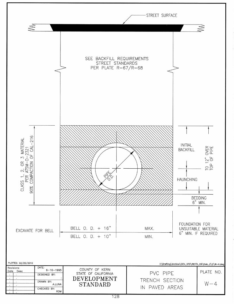
a. Bedding shall be placed and compacted for all main
lines as shown on Plate W-4.
114
b. After placement and compaction of bedding and prior to installation of water main and laterals, the Engineer shall inspect the bedding placement and compaction.
203-3.04 Installation of Pipe, Fittings, and Haunching
PVC pipe exposed to the sun during summer months shall be allowed to cool prior to connection to manholes or placement of haunching. Allowance shall be made for the movement of pipe along the main line and at the laterals. Fittings shall be sized to receive type of pipe used. Installation of fittings shall be in accordance with manufacturers instruction manuals.
Pipe installation and haunching shall conform to Paragraphs 9.1.1, 9.1.2, and 9.1.3 of ASTM-D-2321, AWWA Standards and the following: a. After cooling of the PVC pipe, haunching shall be placed and
compacted for all main lines as shown on plate W-4.
b. Materials used for haunching shall be the same class as that used for bedding.
c. Prior to placement and compaction of initial backfill, the
Engineer shall inspect the placement of the water main and laterals, haunching and compaction.
d. Care shall be exercised in placing haunching material to
prevent damage to or displacement of, the water pipe.
e. Initial backfill shall be placed as required to secure the pipe prior to testing in conformance with Section 203-3.07.
203-3.05 Cleaning
The completed water main shall be flushed and chlorinated in conformance with Section 208-7.
203-3.06 Testing
The completed water main and laterals shall be hydrostatically tested, after pipeline cleaning, but prior to completion of initial backfill and compaction in conformance with Section 208-6.

115
203-3.07 Initial Backfill
Initial backfill shall conform to Paragraphs 9.1.1, 9.1.2, and 9.1.3 of ASTM-D-2321 and the following:
a. After testing of the PVC pipe and placement and
inspection of haunching, initial backfill placement shall be completed and compacted for all main lines as shown on plate W-4.
b. Materials used for initial backfill shall be the same class
as that used for haunching. c. Prior to placement and compaction of backfill, the
Engineer shall inspect the initial backfill and compaction.
d. Care shall be exercised in placing initial backfill material
to prevent damage to or displacement of, the water pipe.
203-3.08 Backfill
The remainder of the trench backfill shall conform with Section 19-3 of the Standard Specifications and as follows:
a. Section 19-3.062, "Slurry Cement Backfill", of the
Standard Specifications is deleted.
b. Backfill material shall be free of all rock or lumps, exceeding six (6) inches maximum dimension.
c. Compacting of backfill material shall be required for all
main lines and laterals as shown on the attached plate.
CHAPTER IV. VALVES AND OTHER APPURTENANCES Sec. 204-1 General All main line gate valves on transmission and/or distribution mains shall be double disc gate valves or butterfly valves and shall conform to the following standards:
204-1.01 Double Disc Gate Valves shall be cast-iron body, all bronze mounted interior, non-rising stem, or for cold water service of 175 PSI working water pressure and shall be in accordance with "AWWA C500", as last revised.
116
204-1.02 Hub End Gate Valves provided with rubber rings shall be in accordance with "AWWA C500" or C509.
204-1.03 Bronze for interior of Gate Valves shall be Grade 1 and shall conform
to current ASTM and State Standards. 204-1.04 Butterfly Valves shall be rubber seated and shall comply with "AWWA
C504", class 125-16 gear operated unless otherwise authorized. Disc shall be of ni-resist alloy cast-iron and shall rotate 90 degrees between the fully open and fully closed positions. Rubber seats shall be securely held in place by nickel cast-iron or type 316 stainless steel retaining segments, and shall not require bonding or cementing to the body.
204-1.05 The butterfly valve standard is not intended to cover valves for
installation where service conditions exceed the shutoff pressures and line velocities stated in Table 1 of "AWWA C504" or on lines supplying fire hydrants.
Sec. 204-2 Valve Boxes and Vaults 204-2-1 A valve box or vault or capped standpipe shall be provided for every
valve installed below the grade. The cover for all valve boxes and vaults placed in the street pavement or any location where there is vehicular traffic shall be traffic rated, metallic or of reinforced concrete.
204-2-2 All valve box caps shall be marked with the word "water", or a "W", or
a suitable identification of the water utility. Sec. 204-3 Air and Vacuum Release Valves Air and vacuum release valves shall be installed in the water system at all points where it is indicated that air pockets may form. The design shall be such as to ensure the release of air automatically from the water main. These valves may also ensure the entrance of air into the water main when the pressure inside the line is below atmospheric pressure. All valves shall be designed for a minimum of 150 PSI operating pressure. The inlet to each valve shall be provided with a gate valve or corporation stop to provide a positive closure between the main pipeline and the air and vacuum release valve. Vent outlets shall be installed above ground in such manner as to preclude back-flow.

117
Sec. 204-4 Check Valves All check valves shall seat readily and completely to assure water tightness. The face of the closure element and valve seat shall be bronze, composition, or other non-corrodible material which will seat tightly under all prevailing conditions of field use. All check valves four (4) inch and larger in size, for use on distribution mains, shall be designed for a minimum of 175 PSI cold water working pressure. Sec. 204-5 Flushouts (Blowoffs) All flushouts (blowoffs) shall be a minimum outlet size of 2" and shall be designed for a minimum operating pressure of 150 PSI. A flushout or fire hydrant shall be installed at the terminus of all dead-end water mains or non-circulating flow water mains.
CHAPTER V. FIRE PROTECTION REQUIREMENTS Sec. 205-1 Fire Hydrants Fire hydrants shall conform with AWWA Specification NO. C-502 or C-503 2-1/2" and 4” national standard threaded connections as required. Hydrant shall be painted rust inhibiting aluminum silver (Rust-Oleum aluminum silver #7715 or equivalent.) For details see Fire Hydrant Detail Standard Drawing, Plate W-1. Sec. 205-2 Bury Bury for hydrants shall conform to AWWA standard specifications C-502 or C-503, height to be sufficient to ensure 30" minimum cover. Bury to be coated with coal tar enamel or coal tar epoxy. Sec. 205-3 Water Supplies for Fire Protection
205-3.01 The fire flow requirements shall be determined by the Fire Chief and shall be computed on the basis of a minimum 20 PSIG residual operating pressure at the point of lowest pressure of the street main from which the flow is measured. In setting the requirements for fire flow, the Fire Chief may be guided by the minimum requirements set forth in Table 1-W, but may require higher standards on the basis of local conditions, exposure, congestion, other regulations, or construction of the buildings. The required fire flows are to be provided in addition to the residential requirements required in Section 202-3.

118
TABLE NO. 1-W - FIRE FLOW REQUIREMENTS
DISTRICT CLASSIFICATION
MINIMUM FIRE FLOW (in gpm)
MINIMUM DURATION (in hours)
MAXIMUM HYDRANT SPACING
Residential Includes: 1 and 2 family dwellings
500
1
660'
Commercial Includes: all commercial uses, hotels, apartments, multiple residence buildings, schools, and colleges
1,500
2
330'
Industrial
1,500
4
330'
205-3.02 The water distribution system shall be provided with valves and other
facilities, such as tanks, so that no point on any lot at the street right-of-way shall be more than one and one-half (1-1/2) times the maximum hydrant spacing from a working hydrant as a result of any single break or shutdown for repairs, except where impractical.
205-3.03 All water mains serving hydrants shall have a minimum nominal
diameter of six inches (6"). Stub lines over 800 feet in length or supporting more than one hydrant shall have a minimum nominal diameter of eight inches (8").
205-3.04 The location, number and type of fire hydrants connected to a water
supply capable of delivering the required fire flow shall be as required and approved by the Fire Chief.
205-3.05 Fire Hydrants shall be installed with a maximum spacing between
hydrants as indicated in Table No. 1-W. A hydrant shall be placed at each intersection except where this would provide excessive hydrant coverage.
Exception: The spacing of hydrants shall have an individual tolerance of 10 percent. However, the average spacing between any three (3) adjacent hydrants shall not exceed the required spacing.
205-3.06 Fire hydrant spacing shall be computed separately for each side of
major highways, divided roadways, canals, or railways. 205-3.07 The last hydrant on a cul-de-sac or stub street shall not be more than
one-half the maximum spacing from the end of the street.

119
205-3.08 Whenever any hydrant or other valve, which is intended for use by the Fire Chief for fire suppression purposes, is installed or replaced, the same shall be installed or replaced in accordance with Plate W-1, "Fire Hydrant Detail."
205-3.09 "Dry Barrel" type fire hydrants shall be provided at all elevations
above 2,500 feet, or where freezing conditions occur. Sec. 205-4 Fire Checks Any connection between a building's fire sprinkler system and the water purveyor's main line shall be protected from backflow in accordance with the Fire Department, Environmental Health Services Department Standards and the water purveyors requirements. Sec. 205-5 Fire Hydrant Barricades Barricades shall be installed where considered necessary by the Fire Chief to protect fire hydrants. Fire hydrant barricades shall not obstruct the outlets and shall consist of 4" diameter standard steel pipe filled with concrete, extending 3' above and 3' below ground and imbedded in concrete 15” (inches) in diameter and 4’ (ft.) deep. All steel pipe above ground shall be painted with a minimum of two (2) coats of primer paint and a finish coat of John Deere Yellow Paint. Fire hydrant barricades shall be installed in accordance with Plate W-6 “Guard Post Installation” at locations specified by the Fire Chief. Sec. 205-6 Location Markers for Fire Hydrants Blue raised retroreflective pavement markers shall be placed on a highway, street, or road to mark fire hydrant locations. They shall not be used for any other purpose. In general, the blue raised retroreflective pavement markers:
a. Should be placed 0.5 foot from the centerline stripe, or approximate center of the pavement where there is no centerline stripe, on the side nearest the fire hydrant.
b. When placed on expressways, freeways and freeway ramps, they should be
placed on the shoulder, 1.0 foot to the right of the edge line, opposite the fire hydrant. Typical marker locations are shown on Figure 3B-102((CA) CMUTCD).
c. In areas at elevations above 2,500 feet and where snow plows are used shall
be recessed, as shown in the Caltrans Department of Transportation’s Standard Plan A20-D.
Because fire hydrants adjacent to freeways may be out of the right-of-way and, in many locations, out of view from the freeway, the Fire Department may require installation of small supplemental signs (S9(CA) and S10(CA) CMUTCD) or markings to indentify the

120
hydrant number or distance to the hydrant. These installations are optional and at the discretion of the Fire Department and Caltrans.
CHAPTER VI. PIPE FITTINGS Sec. 206-1 Cast-Iron Fittings
206-1.01 Bell and Spigot Fittings: All cast-iron bell and spigot fittings shall conform with either "AWWA C110" (Standard, Class D, 173 PSI) or "AWWA C110" (shortbody, 3 inch to 12 inch, 250 PSI) or the long radius type, in class D, 173 PSI water working pressure.
206-1.02 Flange Fitting: All cast-iron flanged fittings shall conform to
"AWWA C110."
CHAPTER VII. WATER SERVICE CONNECTIONS Sec. 207-1 Threads All threads for underground service line fittings and materials for these fittings, corporation and meter stops, shall comply with "AWWA C800”. Sec. 207-2 Service Pipe Size
207-2.01 Water service connections shall be adequately sized to provide 25 psi at the customer connection during peak hourly residential flow. Water service connections shall not be less than 3/4 inch nominal size.
207-2.02 In the event of double service connections for two 3/4" services, the
service pipe from the main to the service connection tee shall be 1" nominal size.
207-2.03 The water service connection shall be equipped with a service valve
or curb stop located two feet outside of the property, or next to the sidewalk where sidewalk is placed.
207-2.04 Where property will be served by two or more water service
connections from different street water mains or supplies, each service connection shall be equipped with a single check valve to prevent cross connection flow.
Sec. 207-3 Water Service Pipe and Tubing All the following materials shall conform either to IAPMO IS 3 "Installation Standard for Copper Plumbing Tube, Pipe and Fittings" or IAPMO 7 "Installation Standard for Polyethylene (PE) Cold Water Building Supply and Yard Piping" in the current adopted edition of the California Plumbing Code.
121
207-3.01 All 3/4 inch and larger water service connections may be seamless
copper water tubing (ASTM B 88) or polyethylene plastic tubing (ASTM D2239, PE 3408).
207-3.02 All 1-1/2 inch and larger water service connections may also use
seamless red brass pipe conforming to (ASTM B 43), or copper pipe conforming to (ASTM B 42).
207-3.03 Water services for either 1-1/2 inch or 2 inch may also use annealed
coiled copper tubing. Sec. 207-4 Corporation Stops All corporation stops, if used, shall be bronze or brass, round, with inlet for either corporation stop (C.S.) thread or iron pipe standard (I.P.S.) thread, and outlet for the type of service pipe used in accordance with AWWA C800. Sec. 207-5 Meter Stops All 3/4 inch and 1 inch (curb) meter stops shall be bronze or brass, with inlet for the type of service pipe used, and outlet for the type or service pipe or meter coupling used. For 1-1/2 inch and 2 inch service, bronze or brass curb stop valve, straight ground key curb stop, or bronze gate valve (Minimum of 200 PSI rated working pressure) may be used. Inlet and outlet shall be appropriate for the type of service pipe or meter flange used. All valves shall be factory hydro-tested to 300 PSI or air-tested to 100 PSI under water. Sec. 207-6 Bronze Gate Valves All 1-1/2 inch through 3 inch gate valves shall be all bronze and comply with "AWWA C500" and ASTM standards. Sec. 207-7 Standard Service Clamps All Service clamps and straps shall be in accordance with AWWA Standards and the pipe manufacturer's recommendations. Sec. 207-8 Repair Service Clamp Where no service clamp is required, and the corporation stop does not seal properly, a repair service clamp shall be used. Sec. 207-9 Solder Joints and Fittings The use of solder containing more than two-tenths of one percent of lead in making joints and fittings in any potable water system is prohibited.

122
CHAPTER VIII. WATER PIPE INSTALLATION
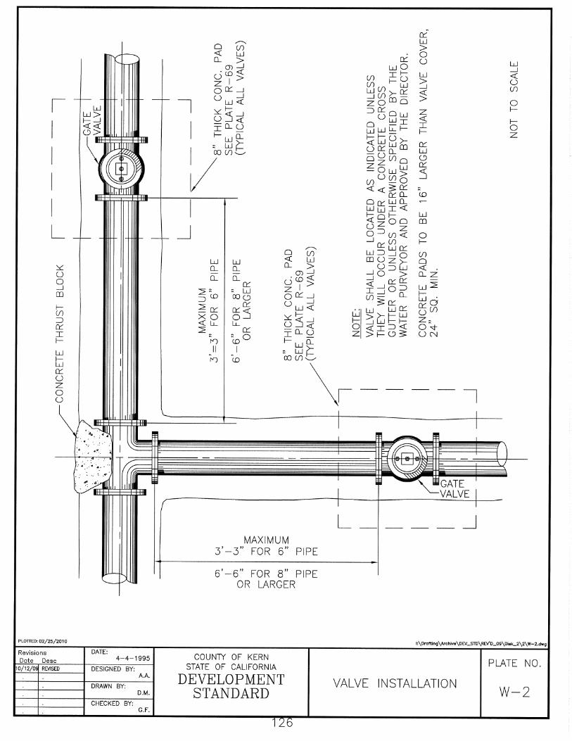
Sec. 208-1 Trench Excavation and Backfilling for Dedicated Streets All pipeline trenches in streets dedicated or offered for dedication shall be excavated, backfilled, and compacted in accordance with this Division and Division I Standards for Streets, see Plate Nos. W-4, R-67 and R-68. Sec. 208-2 Trench Excavation and Backfilling Outside of Dedicated Streets The engineer in charge of the design and construction of the water system shall specify compaction requirements for the backfill of all waterline trenches not located in streets dedicated or offered for dedication. Prior to acceptance of the water system the developer's engineer shall certify by letter that all trenches have been backfilled in accordance with the specifications. Sec. 208-3 Pipe Depth All water mains shall be installed so that the top of the pipe and fittings are not less than 30 inches below finished paving of the street for water mains less than 12 inches in diameter or a minimum cover or 36 inches for mains 12 inches and larger in diameter, unless a greater depth is specified in the excavation and/or encroachment permit. All water service connections shall be installed with a minimum of 30 inch cover within the right of way. Sec. 208-4 Material Handling All pipe material shall be handled, laid, blocked and joined in accordance with the manufacturer's recommendations. All open ends of all water mains being installed shall be properly covered at the end of each day's work to prevent entry of foreign matter, animals, debris, or children. Sec. 208-5 Thrust Devices All tees, plugs, caps, bends of more than 5 degrees, hydrant branches or pipe reducers shall be restrained against movement by use of thrust devices. All reaction or thrust backing devices shall be designed for a minimum static pressure of 200 PSIG. All thrust devices shall be installed in accordance with design data and plans submitted to the engineer. For normal situations, installation shall be in accordance with Plate W-3, "Typical Thrust Block Details." The size and shape of the thrust device shall be designed to prevent movement of the water mains when subjected to the maximum hydrostatic test pressure. Thrust devices shall be cast-in-place concrete, metal harness, or other suitable devices. If the thrust exceeds the bearing value of the surrounding soil, the soil shall be precompacted before placing concrete. To ensure against lateral movement of the water main, valve or fitting where a change in direction of the water main is made by the use of such fittings, a metal harness of tie rods and pipe clamps may be used, except

123
for pipe having rubber-ring type joints. Steel tie rods and pipe clamps shall be galvanized or otherwise rust proofed or painted. All concrete used for thrust blocks shall develop an ultimate compressive strength of 2,000 PSI at 28 days. Sec. 208-6 Testing 208-6.01 Distribution mains shall be tested to a minimum hydrostatic pressure
of design pressure or pipe class. Class 150 pipe shall be tested to a minimum of 150 PSIG. The minimum duration of the test shall be two hours. Before applying the hydrostatic pressure, all entrapped air shall be thoroughly bled off. For all types of water mains, there shall be no visible leakage at any joint or section of pipe and the allowable leakage for the total lengths of all water mains under test shall not exceed that amount specified in "AWWA C600" or “AWWA M23" as appropriate.
208-6.02 All tests shall be made in the presence of the Engineer. Backfill over
joints, valves or fittings shall not exceed the initial backfill until they have been inspected, tested, and approved by the Engineer.
208-6.03 When it is necessary to cover the ditch as soon as the water main is
laid, the authorized representative of the Engineer may permit the backfilling to be completed prior to testing and disinfecting. If the pipe then tested exceeds the allowable leakage, the pipe must be uncovered, repaired, and tested until it meets the allowable leakage.
Sec. 208-7 Disinfecting All new or repaired water mains, pumps, tanks, wells, and other facilities before being placed in service, shall be completely disinfected in accordance with "Procedures for Disinfecting Water Mains, AWWA C601" and any additional requirements, as required by the State Department of Health Services or the Kern County Environmental Health Services Department. Water used for testing shall be potable and contain a minimum residual chlorine content of 50 ppm after a time period of 24 hours, after which the water mains and/or waterworks shall be thoroughly drained and flushed. Before being placed in service, a bacteriological test of the system shall be performed in compliance with the requirements of the appropriate health agency.
CHAPTER IX. STORAGE FACILITIES Sec. 209-1 Design All steel tanks, standpipes, reservoirs and elevated tanks for water storage shall comply with "AWWA D100 Standard for Welded Steel Tanks for Water Storage" or "AWWA D103 Standard for Factory Coated Bolted Steel Tanks for Water Storage," and also meet all foundation and seismic requirements of the Building Code.

124
All pressure (hydromatic) tanks containing more than 1000 U.S. gallons shall conform to the ASME Code for pressure storage and vessels. Sec. 209-2 Repairing and Painting All inspection, repairing, painting and repainting of steel tanks, standpipes, reservoirs, and elevated tanks for water storage shall comply with "AWWA D102."
CHAPTER X. VERTICAL TURBINE PUMPS Sec. 210-1 General All vertical turbine pumps shall comply with "AWWA E-101".
CHAPTER XI. TESTS Sec. 211-1 General
211-1.01 All tests to determine compliance with any of these specifications shall be made within the Continental United States.
211-1.02 If requested by the Engineer, the test results shall be certified by an
established reputable materials testing firm and a copy forwarded to the Engineer.
211.1.03 Any materials delivered to the job site and suspected of damage due
to shipping or handling, if requested by the Engineer, shall be tested again and the test results certified by an approved materials testing firm.