division 700 materials details section 701 … 700 materials details section 701 hydraulic cement...
TRANSCRIPT

DIVISION 700MATERIALS DETAILS
SECTION 701HYDRAULIC CEMENT
701.01 Hydraulic Cement. Hydraulic cement shall conform to the requirements of the following specifications for the type specified or permitted:
Portland Cement ASTM C 150
Blended Hydraulic Cement ASTM C 595
Hydraulic Cement ASTM C 1157
All concrete, including precast, prestressed and pipe shall be constructed with one of the following hydraulic cements unless permitted otherwise.
ASTM C 150 Type I
ASTM C 150 Type II
ASTM C 150 Type V
ASTM C 595 Type IP consisting of no less than 70 percent portland cement
ASTM C 595 Type IP(MS) consisting of no less than 70 percent portland cement
ASTM C 595 Type IP(HS) consisting of no less than 70 percent portland cement
ASTM C 1157 Type GU, consisting of no more than 10 percent limestone
ASTM C 1157 Type MS, consisting of no more than 10 percent limestone
ASTM C 1157 Type HS, consisting of no more than 10 percent limestone
Cement shall be from a preapproved source listed on the Department’s Approved Products List. The cement intended for use on the project shall have been tested and accepted prior to its use. Certified Test Reports showing that the cement meets the specification requirements and supporting this statement with actual test results shall be submitted to the Engineer prior to the tested material being incorporated into the project. Certified Test Reports shall indicate the percentage of pozzolan and limestone incorporated into the cement.
The cement shall be subject to sampling and testing by the Department. Test results that do not meet the physical and chemical requirements may result in the suspension of the use of the cement until the corrections necessary have been taken to insure that the material meets the specifications.
The Contractor shall provide suitable means for storing and protecting the cement against dampness. Cement which, for an reason, has become partially set or which contains lumps of caked cement shall not be used.
Cement salvaged from discarded or used bags shall not be used.
677
701.01

701.02 Fly Ash. Fly ash for concrete shall conform to the requirements of ASTM C 618, Class C or Class F with the following exceptions:
(1) The loss on ignition shall not exceed 3.0 percent.
(2) The CaO in Class F fly ash shall not exceed 18 percent.
Fly ash shall be from a preapproved source listed on the Department’s Approved Products List. The fly ash intended for use on the project shall have been tested and accepted prior to its use. Certified Test Reports showing that the fly ash meets the specification requirements and supporting this statement with actual test results shall be submitted to the Engineer.
Preapproval shall include submission of a report from the supplier documenting the results of testing the fly ash from that source in accordance with the Toxicity Characteristic Leaching Procedure (TCLP) described in 40 CFR 261, Appendix II. The report shall include the results of TCLP testing for heavy metals and other contaminants found in the fly ash. The report shall list the contaminants tested, and the allowable levels for each contaminant tested. A new report shall be submitted for each preapproved source annually. Additional TCLP testing may be required when the Department suspects that the fly ash source may have been contaminated.
The fly ash shall be subject to sampling and testing by the Department. Test results that do not meet the physical and chemical requirements may result in the suspension of the use of fly ash until the corrections necessary have been taken to insure that the material meets the specifications.
701.03 Silica Fume. Silica fume for concrete shall conform to the requirements of ASTM C 1240.
Silica Fume shall be from a preapproved source listed on the Department’s Approved Products List. The silica fume intended for use on the project shall have been tested and accepted prior to its use. Certified Test Reports showing that the silica fume meets the specification requirements and supporting this statement with actual test results shall be submitted to the Engineer. The certification for silica fume shall state the solids content if the silica fume admixture is furnished as slurry.
The silica fume shall be subject to sampling and testing by the Department. Test results that do not meet the physical and chemical requirements may result in the suspension of the use of the silica fume until the corrections necessary have been taken to insure that the material meets the specifications.
678
701.02
SECTION 702BITUMINOUS MATERIALS
702.01 Asphalt Cements.
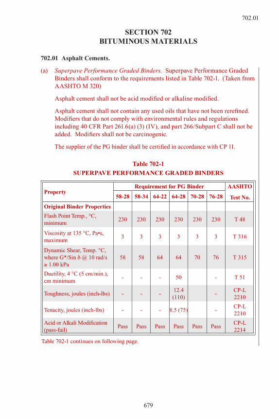
(a) Superpave Performance Graded Binders. Superpave Performance Graded Binders shall conform to the requirements listed in Table 702-1. (Taken from AASHTO M 320)
Asphalt cement shall not be acid modified or alkaline modified.
Asphalt cement shall not contain any used oils that have not been rerefined. Modifiers that do not comply with environmental rules and regulations including 40 CFR Part 261.6(a) (3) (IV), and part 266/Subpart C shall not be added. Modifiers shall not be carcinogenic.
The supplier of the PG binder shall be certified in accordance with CP 11.
Table 702-1
SUPERPAVE PERFORMANCE GRADED BINDERS
PropertyRequirement for PG Binder AASHTO
Test No.58-28 58-34 64-22 64-28 70-28 76-28
Original Binder Properties
Flash Point Temp., °C, minimum
230 230 230 230 230 230 T 48
Viscosity at 135 °C, Pa•s, maximum
3 3 3 3 3 3 T 316
Dynamic Shear, Temp. °C, where G*/Sin d @ 10 rad/s ≥ 1.00 kPa
58 58 64 64 70 76 T 315
Ductility, 4 °C (5 cm/min.), cm minimum
- - - 50 - T 51
Toughness, joules (inch-lbs) - - -12.4 (110)
-CP-L 2210
Tenacity, joules (inch-lbs) - - - 8.5 (75) -CP-L 2210
Acid or Alkali Modification (pass-fail)
Pass Pass Pass Pass Pass PassCP-L 2214
Table 702-1 continues on following page.
679
702.01

Table 702-1 (continued)
PropertyRequirement for PG Binder AASHTO
Test No.58-28 58-34 64-22 64-28 70-28 76-28
RTFO Residue Properties
Mass Loss, percent maximum
1.00 1.00 1.00 1.00 1.00 1.00CP-L 2215
Dynamic Shear, Temp. °C, where G*/Sin d @ 10 rad/s ≥ 2.20 kPa
58 58 64 64 70 76 T 315
Elastic Recovery, 25 °C, percent min.
- - - - 50 50 T 301
Ductility, 4 °C (5 cm/min.), cm minimum
- - - 20 - - T 51
PAV Residue Properties, Aging Temperature 100 °C
R 28
Dynamic Shear, Temp. °C, where G*•Sin d @ 10 rad/s ≤ 5000 kPa
19 16 25 22 25 28 T 315
Creep Stiffness, @ 60 s, Test Temperature in °C
-18 -24 -12 -18 -18 -18 T 315
S, maximum, MPa 300 300 300 300 300 300 T 313
m-value, minimum 0.300 0.300 0.300 0.300 0.300 0.300 T 313
**Direct Tension, Temperature in °C, @ 1 mm/min., where failure strain ≥ 1.0 %
-18 -24 -12 -18 -18 -18 T 314
**Direct tension measurements are required when needed to show conformance to AASHTO M 320.
Acceptance Samples of the PG binder will be taken on the project in accordance with the Schedule in the Field Materials Manual.
The Department will test for acid modification and alkaline modification during the binder certification process. Thereafter, the Department will randomly test for acid modification and alkaline modification.
(b) Dampproofing. Asphalt for damp proofing shall conform to the requirements of ASTM D 449, and the asphaltic primer shall conform to the requirements of ASTM D 41.
702.02 Liquid Asphaltic Materials. Liquid asphaltic materials shall conform to the requirements of AASHTO M 81, M 82, and ASTM D 2026 for the designated types and grades.
680
702.01

702.03 Emulsified Asphalts. Emulsified asphalts shall conform to AASHTO M 140 or M 208 for the designated types and grades. Emulsified asphalt and aggregate used for seal coats shall be sampled and will be tested for information only in accordance with CP-L 2213.
When grade CSS-1h or SS-1h emulsified asphalt is used for tack coat, residue penetration test values shall be 40 to 120.
Emulsified asphalt (HFMS-2S) with a residual penetration greater than 300 dmm (dmm = 0.1 mm) shall conform to all properties listed in AASHTO M 140, Table 1 except that ductility shall be reported for information only.
(a) Emulsion for Seal Coat. Polymerized emulsions for seal coat shall conform to the requirements listed in Table 702-2. Emulsion grades for CRS-2P, CMS-2P, HFRS-2P, and HFMS-2P for seal coat shall be an emulsified blend of polymerized asphalt, water, and emulsifiers. The asphalt cement shall be polymerized prior to emulsification and shall contain at least 3 percent polymer by weight of asphalt cement. The emulsion standing undisturbed for a minimum of 24 hours shall show no white, milky separation but shall be smooth and homogeneous throughout. The emulsion shall be pumpable and suitable for application through a distributor.
Emulsion grade CRS-2R for seal coat shall be an emulsified blend of asphalt, styrene-butadiene-rubber (SBR) latex polymer, water and emulsifiers. The emulsion shall contain at least 3 percent polymer solids by weight of asphalt cement. The polymer will be incorporated by comilling into the emulsion.
Table 702-2
POLYMERIZED EMULSIONS FOR SEAL COATS
PropertyCRS-
2PCRS-
2RCMS-
2PHFRS-
2PHFMS-
2PAASHTO Test No.
Tests on Emulsion
Viscosity1, at 50 ºC, Say-bolt- Furol, s
min 50 50 50 50 50T 59
max 450 450 450 450 450
Storage stability, 24 hr, % max
1.0 1.0 1.0 1.0 1.0 T 59
Particle charge test Positive Positive Positive T 59
Sieve test, % max 0.10 0.10 0.10 0.10 0.10 T 59
Demulsibility1, % min 40 40 40 T 59
Oil Distillate by volume, % max or range
3.0 3.0 3.0 3.0 3.0 T 59
Residue by distillation/ evaporation, % min3 653 653 653 653 653 T 59/
CP-L 22122
Table 702-2 continues on following page.
681
702.03
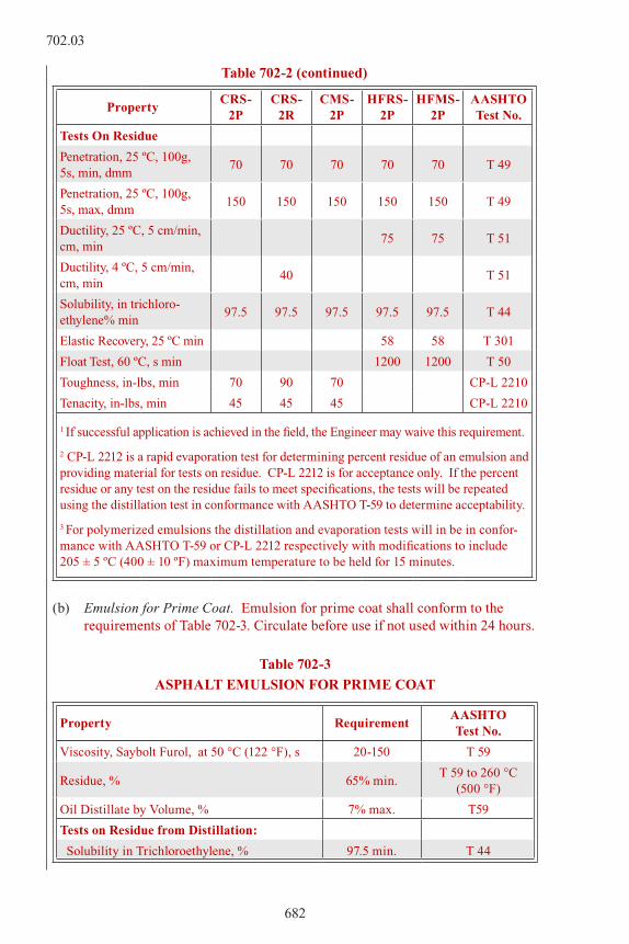
Table 702-2 (continued)
PropertyCRS-
2PCRS-
2RCMS-
2PHFRS-
2PHFMS-
2PAASHTO Test No.
Tests On Residue
Penetration, 25 ºC, 100g, 5s, min, dmm
70 70 70 70 70 T 49
Penetration, 25 ºC, 100g, 5s, max, dmm
150 150 150 150 150 T 49
Ductility, 25 ºC, 5 cm/min, cm, min
75 75 T 51
Ductility, 4 ºC, 5 cm/min, cm, min
40 T 51
Solubility, in trichloro-ethylene% min
97.5 97.5 97.5 97.5 97.5 T 44
Elastic Recovery, 25 ºC min 58 58 T 301
Float Test, 60 ºC, s min 1200 1200 T 50
Toughness, in-lbs, min 70 90 70 CP-L 2210
Tenacity, in-lbs, min 45 45 45 CP-L 2210
1 If successful application is achieved in the field, the Engineer may waive this requirement.
2 CP-L 2212 is a rapid evaporation test for determining percent residue of an emulsion and providing material for tests on residue. CP-L 2212 is for acceptance only. If the percent residue or any test on the residue fails to meet specifications, the tests will be repeated using the distillation test in conformance with AASHTO T-59 to determine acceptability.
3 For polymerized emulsions the distillation and evaporation tests will in be in confor-mance with AASHTO T-59 or CP-L 2212 respectively with modifications to include 205 ± 5 ºC (400 ± 10 ºF) maximum temperature to be held for 15 minutes.
(b) Emulsion for Prime Coat. Emulsion for prime coat shall conform to the requirements of Table 702-3. Circulate before use if not used within 24 hours.
Table 702-3
ASPHALT EMULSION FOR PRIME COAT
Property RequirementAASHTO Test No.
Viscosity, Saybolt Furol, at 50 °C (122 °F), s 20-150 T 59
Residue, % 65% min.T 59 to 260 °C
(500 °F)
Oil Distillate by Volume, % 7% max. T59
Tests on Residue from Distillation:
Solubility in Trichloroethylene, % 97.5 min. T 44
682
702.03

(c) Recycling Agent. Recycling Agent for Item 406, Cold Bituminous Pavement (Recycle), shall be either a high float emulsified asphalt (polymerized) or an emulsified recycling agent as follows:
1. High Float Emulsified Asphalt (Polymerized). High Float Emulsified Asphalt (Polymerized) for Cold Bituminous Pavement (Recycle) shall be an emulsified blend of polymer modified asphalt, water, and emulsifiers conforming to Table 7024 for HFMS2sP. The asphalt cement shall be polymerized prior to emulsification, and shall contain at least 3 percent polymer.
The emulsion standing undisturbed for a minimum of 24 hours shall show no white, milky separation, and shall be smooth and homogeneous throughout.
The emulsion shall be pumpable and suitable for application through a pressure distributor.
Table 702-4
HIGH FLOAT EMULSIFIED ASPHALT
(POLYMERIZED) (HFMS2sP)
PropertyRequirement
AASHTO Test
Minimum Maximum
Tests on Emulsion:
Viscosity, Saybolt Furol at 50 °C (122 °F), sec 50 450 T 59
Storage Stability test, 24 hours, % 1 T 59
Sieve test, % 0.10 T 59
Residue, %1 65 T 59
Oil distillate by volume, % 1 7 T 59
Tests on Residue:
Penetration, 25 °C (77 °F), 100g, 5 sec 150 3002 T 49
Float Test, 60 °C (140 °F), sec 1200 T 50
Solubility in TCE, % 97.5 T 44
Elastic Recovery, 4 °C (39.2 °F), % 50 T 301
1 400 ± 10° F maximum temperature to be held for 15 minutes.2 When approved by the Engineer, Emulsified Asphalt (HFMS-2sP) with a residual
penetration greater than 300 dmm may be used with Cold Bituminous Pavement (Recycle) to address problems with cool weather or extremely aged existing pavement. Emulsified Asphalt (HFMS-2sP) with a residual penetration greater than 300 dmm shall meet all properties listed in Table 702-4 except that Elastic Recovery shall be reported for information only.
683
702.03

2. Emulsified Recycling Agent. Emulsified Recycling Agent for use in Cold Bituminous Pavement (Recycle) shall conform to the requirements in Table 702-5.
Table 702-5
EMULSIFIED RECYCLING AGENT
PropertyRequirement
TestMinimum Maximum
Tests on Emulsion:
Viscosity @ 25 °C, SFS 20 200 ASTM D 244
Pumping Stability Pass GB Method1
Sieve Test, %w 0.1 ASTM D 2442
Cement Mixing, %w 2.0 ASTM D 244
Particle Charge Positive ASTM D 244
Conc. Of Oil Phase 64 ASTM D 2443
Tests on Residue:
Viscosity @ 60 °C , CST 2000 4000 ASTM D 2170
Flash Point, COC, °C (° F) 232 ASTM D 92
Maltenes Dist. PC+A1
Ratio4 S+A2 0.3 0.6
ASTMD 2006
PC/S Ratio 0.4ASTMD 2006
Asphaltenes, % max. 11.0ASTMD 2006
1 Pumping stability is determined by charging 450 ml of emulsion into a one liter beaker and circulating the emulsion through a gear pump (Roper 29.B22621) having a 6.3 mm (1/4 inch) inlet and outlet. The emulsion passes if there is no significant separation after circulating ten minutes.
2 Test procedure identical with ASTM D 244 except that distilled water shall be used in place of 2 percent sodium oleate solution.
3 ASTM D 244 Evaporation Test for percent of residue is modified by heating 50 gram sample to 149°C (300 °F) until foaming ceases, then cooling immediately and calcu-lating results.
4 In the Maltenes Distribution Ratio Test by ASTM Method D 2006.PC = Polar Compounds S = SaturatesA
1 = First Acidaffin A
2 = Second Acidaffins
684
702.03

702.04 Rejuvenating Agents. Asphalt rejuvenating agents (ARA) shall be composed of a petroleum resin-oil base uniformly emulsified with water and shall conform to the physical and chemical requirements of Table 702-6 or ASTM D 4552.
Table 702-6
ASPHALT REJUVENATING AGENT
Property Test Method Requirement
Viscosity, S.F., @ 25 °C (77 °F), s ASTM D 244 20-401Residue, % min. ASTM D 244 60-65
2Miscibility Test ASTM D 244No
coagulation3Sieve Test, % max. ASTM D 244 0.10
Particle Charge Test ASTM D 244 Positive
ASTM D244 (Mod):
Viscosity, 60 °C (140 °F), mm2/s ASTM D 445 100 - 200
Flash Point, COC, °C, min. ASTM D 92 196
Asphaltenes, % max.ASTMD2006
1.0
4Maltenes Dist. PC+A1
Ratio S+A2
ASTMD 2006
0.3-0.6
Saturated Hydrocarbons, %ASTMD 2006
21-28
1 ASTM D244 Modified Evaporation Test for percent of residue is made by heating 50-gram sample to 149 °C (300 °F) until foaming ceases, then cooling immediately and calculating results.
2 Test procedure identical with ASTM D244 except that 0.02 Normal Calcium Chloride solution shall be used in place of distilled water.
3 Test procedure identical with ASTM D244 except that distilled water shall be used in place of 2% sodium oleate solution.
4 In the Maltenes Distribution Ratio Test by ASTM Method D4124:PC = Polar Compounds S = SaturatesA
1 = First Acidaffin A
2 = Second Acidaffins
For hot-in-place recycling ARA-1P is an acceptable alternative to ARA. ARA-1P shall meet the requirements below:
Emulsified Polymer Modified Asphalt Rejuvenating Agent (ARA-1P) for use in hot-in-place recycling of bituminous pavements shall be modified with a minimum of 1.5 percent styrene-butadiene solution polymer. The finished product shall conform to the physical requirements listed in Table 702-7 below.
685
702.04

Table 702-7
ARA 1P
Property Test Method Min Max
Test on Emulsion
Viscosity, Saybolt-Furol @ 77 ºF, s ASTM D 244 100
Residue @ 350 ºF, % ASTM D 244 Mod 60
Sieve Test, % ASTM D 244 0.10
Oil distillate, % ASTM D 244 2.0
Test on Residue
Penetration @ 39.2 ºF, 100g, 5s, dmm ASTM D-5 Modified 150 250
Asphaltenes, % ASTM D 4124 15
702.05 (unused)
702.06 Hot Poured Joint and Crack Sealant. Hot poured material for filling joints and cracks shall conform to the requirements of ASTM D 6690, Type I or II. The concrete blocks used in the Bond Test shall be prepared in accordance with CP-L 4101.
Sealant material shall be supplied pre-blended, pre-reacted, and prepackaged. If supplied in solid form the sealant material shall be cast in a plastic or other dissolvable liner having the capability of becoming part of the crack sealing liquid. The sealant shall be delivered in the manufacturer’s original sealed container.
Each container shall be legibly marked with the manufacturer’s name, the trade name of the sealer, the manufacturer’s batch or lot number, the application temperature range, the recommended application temperature, and the safe heating temperature.
The sealant shall be listed in CDOT’s Approved Products List prior to use.
686
702.04

SECTION 703AGGREGATES
All sieve sizes and designations described in this section refer to laboratory sieves having square openings and conforming to ASTM E 11.
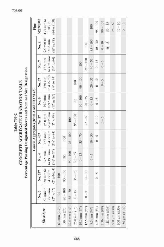
Where the Contract refers to a nominal size aggregate, the nominal size shall conform to the gradation in Table 703-1 below.
Table 703-1
DEFINITION OF NOMINAL AGGREGATES
Nominal SizeMaterial passing the designated sieve by weight
100% 90% to 100% No more than 90%
50 mm (2") 63 mm (2½") 50 mm (2") 37.5 mm (1½")
37.5 mm (1½") 50 mm (2") 37.5 mm (1½") 25.0 mm (1")
25.0 mm (1") 37.5 mm (1½") 25.0 mm (1") 19.0 mm (¾")
19.0 mm (¾") 25.0 mm (1") 19.0 mm (¾") 12.5 mm (½")
12.5 mm (½") 19.0 mm (¾") 12.5 mm (½") 9.5 mm (3/8")
9.5 mm (3/8") 12.5 mm (½") 9.5 mm (3/8") 4.75 mm (#4)
The grading and composition requirements for coarse and fine aggregates for concrete are set forth in Table 703-2.
687
703.00
Tab
le 7
03-2
CO
NC
RE
TE
AG
GR
EG
AT
E G
RA
DA
TIO
N T
AB
LE
Per
cent
age
Pas
sin
g D
esig
nat
ed S
ieve
s an
d N
omin
al S
ize
Des
ign
atio
n
Sie
ve S
ize
Coa
rse
Agg
rega
tes
(fro
m A
ASH
TO
M 4
3)F
ine
Agg
rega
teN
o. 3
No.
357
No.
4N
o. 4
67N
o. 5
7N
o. 6
No.
67
No.
7N
o. 8
50 m
m to
25
.0 m
m
(2"
to 1
")
50 m
m to
4.
75 m
m
(2"
to N
o. 4
)
37.5
mm
to
19.
0 m
m
(1½
" to
¾")
37.5
mm
to
4.7
5 m
m
(1½
" to
#4)
25.0
mm
to
4.7
5 m
m
(1"
to #
4)
19.0
mm
to
9.5
mm
(¾
" to
3/8")
19.0
mm
to
4.7
5 m
m
(¾"
to #
4)
12.5
mm
to
4.7
5 m
m
(½"
to #
4)
9.5
mm
to
2.36
mm
(3/8
" to
#8)
4.75
mm
to
150
µm
(#4
to #
100)
63 m
m (
2½")
100
100
50 m
m (
2")
90 –
100
95 –
100
100
100
37.5
mm
(1½
")35
– 7
090
– 1
0095
– 1
0010
0
25.0
mm
(1")
0 –
1535
– 7
020
– 5
595
– 1
0010
010
0
19.0
mm
(¾
")0
– 15
35 –
70
90 –
100
90 –
100
100
12.5
mm
(½
")0
– 5
10 –
30
25 –
60
20 –
55
90 –
100
100
9.5
mm
(3/8
")0
– 5
10 –
30
0 –
1520
– 5
540
– 7
085
– 1
0010
0
4.75
mm
(#4
)0
– 5
0 –
50
– 10
0 –
50
– 10
0 –
1510
– 3
095
– 1
00
2.36
mm
(#
8)0
– 5
0 –
50
– 5
0 –
1080
– 1
00
1.18
mm
(#1
6)0
– 5
50 –
85
600
µm (
#30)
25 –
60
300
µm (
#50)
10 –
30
150
µm (
#100
)2
– 10
688
703.00

703.01 Fine Aggregate for Concrete. Fine aggregate for concrete shall conform to the requirements of AASHTO M 6. The amount of material finer than 75 µm (No. 200) sieve shall not exceed three percent by dry weight of fine aggregate, when tested in accordance with AASHTO T 11 or Colorado Procedure 31, Method D, unless otherwise specified. The minimum sand equivalent, as tested in accordance with AASHTO T 176 shall be 80 unless otherwise specified. The fineness modulus, as determined by AASHTO T 27, shall not be less than 2.50 or greater than 3.50 unless otherwise approved.
703.02 Coarse Aggregate for Concrete. Coarse aggregate for concrete shall conform to the requirements of AASHTO M 80, except that the percentage of wear shall not exceed 45 when tested in accordance with AASHTO T 96. Coarse aggregate shall conform to the grading in Table 703-2. Sizes 357 and 467 shall each be furnished in two separate sizes and combined in the plant in the proportions necessary to conform to the grading requirements. Compliance with grading requirements will be based on the combination and not on each individual stockpile.
703.03 Aggregate for Bases. Aggregates for bases shall be crushed stone, crushed slag, crushed gravel, natural gravel, or crushed reclaimed concrete or asphalt material which conforms to the quality requirements of AASHTO M 147 except that the requirements for the ratio of minus 75 µm (No. 200) sieve fraction to the minus No. 40 sieve fraction, stated in 2.2.2 of AASHTO M 147, shall not apply. The requirements for the Los Angeles wear test (AASHTO T 96) shall not apply to Class 1, 2, and 3. Aggregate for bases shall meet the grading requirements of Table 703-3 for the class specified for the project, unless otherwise specified.
The liquid limit shall be as shown in Table 703-3 and the plasticity index shall not exceed six when the aggregate is tested in accordance with AASHTO T89 and T 90 respectively.
Table 703-3CLASSIFICATION FOR AGGREGATE BASE COURSE
Sieve Size
Mass Percent Passing Square Mesh Sieves
LL not greater than 35 LL not greater than 30
Class 1 Class 2 Class 3 Class 4 Class 5 Class 6 Class 7150mm (6") 100
100mm (4") 100
75mm (3") 95-100
60mm (2 ½") 100
50mm (2") 95-100 100
37.5mm (2") 90-100 100
25mm (1") 95-100 100
19mm (3/4") 50-90 100
4.75mm (#4) 30-65 30-50 30-70 30-65
2.36mm (#8) 25-55 20-85
75 µm (#200) 3-15 3-15 20 max 3-12 3-15 3-12 5-15
NOTE: Class 3 material shall consist of bank or pit run material.
689
703.03
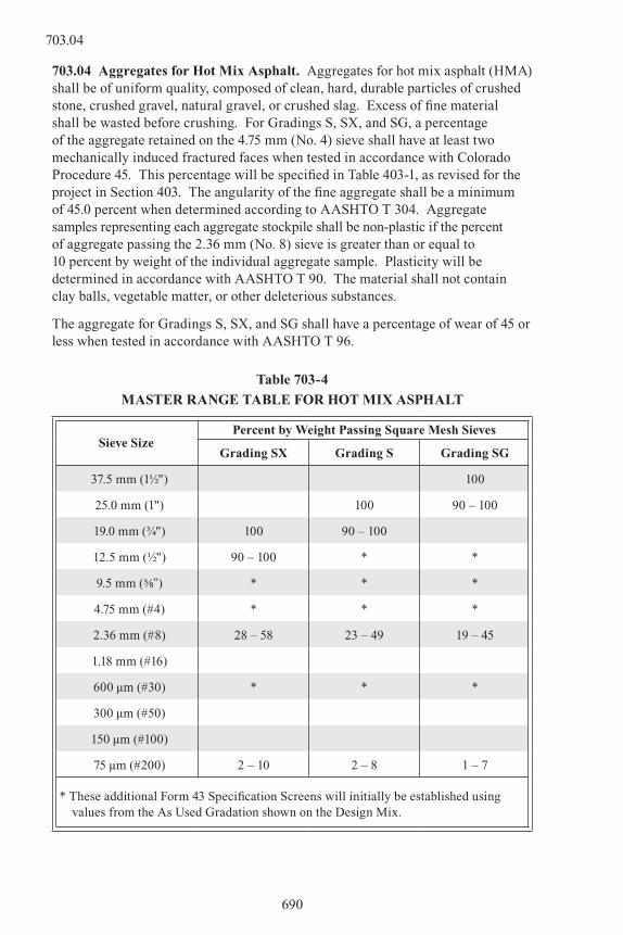
703.04 Aggregates for Hot Mix Asphalt. Aggregates for hot mix asphalt (HMA) shall be of uniform quality, composed of clean, hard, durable particles of crushed stone, crushed gravel, natural gravel, or crushed slag. Excess of fine material shall be wasted before crushing. For Gradings S, SX, and SG, a percentage of the aggregate retained on the 4.75 mm (No. 4) sieve shall have at least two mechanically induced fractured faces when tested in accordance with Colorado Procedure 45. This percentage will be specified in Table 403-1, as revised for the project in Section 403. The angularity of the fine aggregate shall be a minimum of 45.0 percent when determined according to AASHTO T 304. Aggregate samples representing each aggregate stockpile shall be non-plastic if the percent of aggregate passing the 2.36 mm (No. 8) sieve is greater than or equal to 10 percent by weight of the individual aggregate sample. Plasticity will be determined in accordance with AASHTO T 90. The material shall not contain clay balls, vegetable matter, or other deleterious substances.
The aggregate for Gradings S, SX, and SG shall have a percentage of wear of 45 or less when tested in accordance with AASHTO T 96.
Table 703-4
MASTER RANGE TABLE FOR HOT MIx ASPHALT
Sieve SizePercent by Weight Passing Square Mesh Sieves
Grading Sx Grading S Grading SG
37.5 mm (1½") 100
25.0 mm (1") 100 90 – 100
19.0 mm (¾") 100 90 – 100
12.5 mm (½") 90 – 100 * *
9.5 mm (3/8") * * *
4.75 mm (#4) * * *
2.36 mm (#8) 28 – 58 23 – 49 19 – 45
1.18 mm (#16)
600 µm (#30) * * *
300 µm (#50)
150 µm (#100)
75 µm (#200) 2 – 10 2 – 8 1 – 7
* These additional Form 43 Specification Screens will initially be established using values from the As Used Gradation shown on the Design Mix.
690
703.04
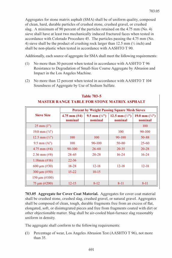
Aggregates for stone matrix asphalt (SMA) shall be of uniform quality, composed of clean, hard, durable particles of crushed stone, crushed gravel, or crushed slag. A minimum of 90 percent of the particles retained on the 4.75 mm (No. 4) sieve shall have at least two mechanically induced fractured faces when tested in accordance with Colorado Procedure 45. The particles passing the 4.75 mm (No. 4) sieve shall be the product of crushing rock larger than 12.5 mm (½ inch) and shall be non-plastic when tested in accordance with AASHTO T 90.
Additionally, each source of aggregate for SMA shall meet the following requirements:
(1) No more than 30 percent when tested in accordance with AASHTO T 96 Resistance to Degradation of Small-Size Coarse Aggregate by Abrasion and Impact in the Los Angeles Machine.
(2) No more than 12 percent when tested in accordance with AASHTO T 104 Soundness of Aggregate by Use of Sodium Sulfate.
Table 703-5
MASTER RANGE TABLE FOR STONE MATRIx ASPHALT
Sieve Size
Percent by Weight Passing Square Mesh Sieves
4.75 mm (#4) nominal
9.5 mm (3/8") nominal
12.5 mm (½") nominal
19.0 mm (¾") nominal
25 mm (1") 100
19.0 mm (¾") 100 90-100
12.5 mm (½") 100 100 90-100 50-88
9.5 mm (3/8") 100 90-100 50-80 25-60
4.75 mm (#4) 90-100 26-60 20-35 20-28
2.36 mm (#8) 28-65 20-28 16-24 16-24
1.18mm (#16) 22-36
600 µm (#30) 18-28 12-18 12-18 12-18
300 µm (#50) 15-22 10-15
150 µm (#100)
75 µm (#200) 12-15 8-12 8-11 8-11
703.05 Aggregate for Cover Coat Material. Aggregates for cover coat material shall be crushed stone, crushed slag, crushed gravel, or natural gravel. Aggregates shall be composed of clean, tough, durable fragments free from an excess of flat, elongated, soft, or disintegrated pieces and free from fragments coated with dirt or other objectionable matter. Slag shall be air-cooled blast-furnace slag reasonably uniform in density.
The aggregate shall conform to the following requirements:
(1) Percentage of wear, Los Angeles Abrasion Test (AASHTO T 96), not more than 35.
691
703.05

(2) When blast-furnace slag is used, weight per cubic foot shall be at least 70 pounds.
(3) For Type I, II, or IV cover coat material, 90 percent by weight of the particles retained on the 4.75 mm (No. 4) sieve shall have at least two fractured faces when tested in accordance with Colorado Procedure 45.
(4) Lightweight aggregate used for cover coat material shall be an aggregate prepared by expanding shale, clay, or slate in a rotary fired kiln. Lightweight aggregate shall have a dry loose unit weight of 35 to 55 pounds per cubic foot determined in accordance with AASHTO T 19, Shoveling Procedure. The total mass of the test sample of lightweight aggregate used in AASHTO T 96 (Los Angles Abrasion) shall be 2000 g.
Table 703-6
GRADATION SPECIFICATIONS FOR COVER COAT AGGREGATE
Sieve Size
Percent by Weight Passing Square Mesh Sieve
9.5 mm (3/8")Type 1
12.5 mm (½")Type II
19.0 mm (¾")*Type IV
19.0 mm (¾") 100
12.5 mm (½") 100 95-100
9.5 mm (3/8") 100 70-100 60-80
4.75 mm (No. 4) 0-15 0-4 0-10
75 µm (# 200) 0-1.0 0-1.0 0-1.0
*Type IV shall be used only with lightweight aggregates.
703.06 Mineral Filler. Mineral filler shall conform to the requirements of AASHTO M 17 and shall consist of rock dust, slag dust, hydrated lime, hydraulic cement, fly ash, or other suitable mineral matter. It shall be free of organic impurities and agglomerations. When used, it shall be dry enough to flow freely.
Mineral filler shall be graded within the following limits:
Sieve Size Mass Percent Passing
600 µm (No. 30) 100
300 µm (No. 50) 95-100
75 µm (No. 200) 70-100
Mineral filler shall have a plasticity index not greater than four excluding hydrated lime and hydraulic cement.
692
703.05

703.07 Bed Course Material.
(a) Bed course material for sidewalks, curbing, and bikeways shall consist of cinders, sand, slag, gravel, crushed stone, or other approved material of such gradation that all particles shall pass through a sieve having 19.0 mm (¾ inch) square openings.
(b) Bed course material for slope protection, or riprap filter blanket shall be a porous, free draining material consisting of sand, gravel, cinders, slag, crushed stone, or other approved free draining material. This material shall meet the following gradation requirements:
Sieve SizeMass Percent Passing Square Mesh Sieves
75 mm (3 inch) 100
4.75 mm (No. 4) 20-65
75 µm (No. 200) 0-10
703.08 Structure Backfill Material.
(a) Class I structure backfill shall meet the following gradation requirements:
Sieve SizeMass Percent Passing Square Mesh Sieves
50 mm (2 inch) 100
4.75 mm (No. 4) 30-100
300 µm (No. 50) 10-60
75 µm (No. 200) 5-20
In addition this material shall have a liquid limit not exceeding 35 and a plasticity index of not over six when determined in conformity with AASHTO T 89 and T 90 respectively.
(b) Class 2 structure backfill shall be composed of suitable materials developed on the project. To be suitable for use under this classification, backfill shall be free of frozen lumps, wood, or other organic material. If the material contains rock fragments that, in the opinion of the Engineer, will be injurious to the structure, the native material shall not be used for backfilling and the Contractor shall furnish Class 1 structure backfill material at the contract unit price. If contract unit price does not exist for Class I structure backfill, it will be paid for in accordance with subsection 104.03.
703.09 Filter Material. Filter material shall consist of free draining sand, gravel, slag, or crushed stone. The grading requirements are set forth in Table 703-7.
693
703.09
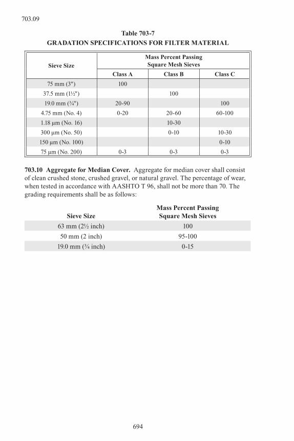
Table 703-7
GRADATION SPECIFICATIONS FOR FILTER MATERIAL
Sieve Size
Mass Percent PassingSquare Mesh Sieves
Class A Class B Class C
75 mm (3") 100
37.5 mm (1½") 100
19.0 mm (¾") 20-90 100
4.75 mm (No. 4) 0-20 20-60 60-100
1.18 µm (No. 16) 10-30
300 µm (No. 50) 0-10 10-30
150 µm (No. 100) 0-10
75 µm (No. 200) 0-3 0-3 0-3
703.10 Aggregate for Median Cover. Aggregate for median cover shall consist of clean crushed stone, crushed gravel, or natural gravel. The percentage of wear, when tested in accordance with AASHTO T 96, shall not be more than 70. The grading requirements shall be as follows:
Sieve SizeMass Percent Passing Square Mesh Sieves
63 mm (2½ inch) 100
50 mm (2 inch) 95-100
19.0 mm (¾ inch) 0-15
694
703.09

SECTION 704MASONRY UNITS
704.01 Clay or Shale Brick. Brick shall conform to the requirements of one of the following specifications:
Sewer and Manhole Brick-AASHTO M 91. Building Brick-AASHTO M 114.
704.02 Concrete Brick. Concrete brick shall conform to the requirements of ASTM C 55.
704.03 Concrete Masonry Blocks. Concrete masonry blocks may be rectangular or segmented and, when specified, shall have ends shaped to provide interlock at vertical joints. The blocks shall conform to the requirements of ASTM C 139, or, for hollow blocks, to ASTM C 90. Dimensions and tolerances shall conform to the above applicable requirements or those specified on the plans.
704.04 Masonry Mortar. Masonry mortar shall be Type S conforming to ASTM C 270.
695
704.04

SECTION 705JOINT, WATERPROOFING,
AND BEARING MATERIALS
705.01 Joint Fillers.
(a) Joint Sealant with Backer Rod. The joint sealant material shall be a silicone that is on the Department’s Approved Products List. The silicone materials shall be stored and applied in accordance with manufacturer’s recommendations, but they shall not be exposed to ambient temperatures in excess of 125 °F or stored in direct sunlight. The backer rod placed prior to joint sealant shall be constructed of closed cell polyethylene strand as approved.
(b) Preformed Joint Fillers. Preformed fillers for joints shall conform to the requirements of AASHTO M 213 and shall be punched to admit the dowels where called for on the plans. The filler for each joint shall be furnished in a single piece for the full depth and thickness required for the joint unless otherwise authorized by the Engineer. When the use of more than one piece is authorized for a joint, the abutting ends shall be fastened securely, and held accurately to shape, by stapling or other positive fastening satisfactory to the Engineer.
705.02 (unused)
705.03 Gaskets. Rubber gasketed joints shall conform to the requirements of AASHTO M 315 and shall be flexible and able to withstand expansion, contraction, and settlement.
All rubber gaskets shall be stored in as cool a place as practicable, preferably at 70 °F or less. Rubber gaskets shall not be exposed to the direct rays of the sun for more than 72 hours.
Rubber gaskets, of the type requiring lubrication, shall be lubricated with the lubricant recommended and supplied by the manufacturer of the pipe.
705.04 Pipe Joint Sealing Compounds. Joint sealing compounds for concrete pipe shall conform to the requirements of AASHTO M 198.
Joint sealants for metal pipe shall conform to the pipe manufacturer’s recommendations.
705.05 Compression Ring. Compression ring jointing connections for clay pipe, made of resilient material, shall conform to the requirements of ASTM C 425.
705.06 Bearing Materials
696
705.01

Table 705-1POLYISOPRENE (NATURAL RUBBER) ELASTOMER
Specimen PropertiesASTM
TestProcedure
Requirements
50 Duro 60 Duro 70 Duro
Physical Properties
Hardness D 2240 50 ± 5 60 ± 5 70 ± 5
Tensile Strength, MPa Minimum (psi). D 412 15.5 (2250) 15.5 (2250) 15.5 (2250)
Ultimate Elongation, % Minimum D 412 450 400 300
Heat Resistance, 70 Hr./70 °C (158 °F)
Change in Durometer Hardness, Maximum Points
+10 +10 +10
Change in Tensile Strength, % Maximum
D 573 -25 -25 -25
Change in Ultimate Elongation, % Maximum
D573 -25 -25 -25
Compression Set D 395
% Maximum, 22 Hr./70 °C (158 °F) Method B 25 25 25
Ozone Resistance, 20% Strain25 ppm Ozone in Air by Volume38 ± 1 °C (100 ± 2 °F)/48 Hr.Mounting Procedure ASTM D 518, Procedure A
D 1149No
CracksNo
CracksNo
Cracks
AdhesionBond Made during Vulcanization,N per mm (Lb. per Inch)
D 429, B 7 (40) 7 (40) 7 (40)
Low Temperature Brittleness:Grade 3 at -40 °C (-40 °F)Grade 4 at -48 °C (-55 °F)Grade 5 at -57 °C (-70 °F)
D 746Procedure
B
NoFailure
NoFailure
NoFailure
Instantaneous Thermal Stiffening:Grade 3 at -40 °C (-40 °F)Grade 4 at -46 °C (-50 °F)Grade 5 at -54 °C (-65 °F)
D 10431
3
1
3
1
3
Low Temperature Crystallization: D 4014Quad Shear
Test as described
in Annex A
2
3
2
3
2
3
Grade 3, 14 Days at -26 °C (-15 °F)Grade 4, 21 Days at -37 °C (-35 °F)Grade 5, 28 Days at -37 °C (-35 °F)
1 Stiffness at test temperature shall not exceed 4 times the stiffness measured at 23 °C (73 °F).2 Stiffness at test time and temperature shall not exceed 4 times the stiffness measured at
23 °C (73 °F) with no time delay. The stiffness shall be measured with a quad shear test rig in an enclosed freezer unit. The test specimens shall be taken from a randomly selected bearing. A ± 25° strain cycle shall be used and a complete cycle of strain shall be applied with a period of 100 seconds. The first ¾ cycle of strain shall be discarded and the stiffness shall be determined by the slope of the force deflection curve for the next ½ cycle of loading.
3 ASTM D 1043 refers to the “Modulus of Rigidity” while ASTM D 4014 refers to the “Shear Modulus Stiffness”. The word “stiffness” is used to describe both terms.
697
705.06

Table 705-2CHLOROPRENE (NEOPRENE) ELASTOMER
Specimen PropertiesASTM
TestProcedure
Requirements
50 Duro 60 Duro 70 Duro
Physical Properties
Hardness D 2240 50 ± 5 60 ± 5 70 ± 5
Tensile Strength, MPa Minimum (psi). D 412 17.2(2500) 17.2(2500) 17.2(2500)
Ultimate Elongation, % Minimum D 412 400 350 300
Heat Resistance, 70 Hr./ 70 °C (158 °F)
Change in Durometer Hardness, Maximum Points
+15 +15 +15
Change in Tensile Strength, % Maximum
D 573 -15 -15 -15
Change in Ultimate Elongation, % Maximum
D573 -40 -40 -40
Compression Set D 395
% Maximum, 22 Hr./100 °C (212 °F) Method B 35 35 35
Ozone Resistance, 20% Strain100 ppm Ozone in Air by Volume38 ± 1 °C (100 ± 2 °F)/ 100 Hr.Mounting Procedure ASTM D 518, Procedure A
D 1149No
CracksNo
CracksNo
Cracks
AdhesionBond Made during Vulcanization,N per mm (Lb. per Inch)
D 429, B 7 (40) 7 (40) 7 (40)
Low Temperature Brittleness:Grade 3 at -40 °C (-40 °F)Grade 4 at -48 °C (-55 °F)Grade 5 at -57 °C (-70 °F)
D 746Procedure
B
NoFailure
NoFailure
NoFailure
Instantaneous Thermal Stiffening:
Grade 3 at -40 °C (-40 °F)Grade 4 at -46 °C (-50 °F)Grade 5 at -54 °C (-65 °F)
D 10431
3
1
3
1
3
Low Temperature Crystallization: D 40142
3
2
3
2
3
Grade 3, 14 Days at -26 °C (-15 °F)Grade 4, 21 Days at -37 °C (-35 °F)Grade 5, 28 Days at -37 °C (-35 °F)
Quad Shear Test as
described in Annex A
1 Stiffness at test temperature shall not exceed 4 times the stiffness measured at 23 °C (73 °F).2 Stiffness at test time and temperature shall not exceed 4 times the stiffness measured at
23 °C (73 °F) with no time delay. The stiffness shall be measured with a quad shear test rig in an enclosed freezer unit. The test specimens shall be taken from a randomly selected bearing. A ± 25° strain cycle shall be used and a complete cycle of strain shall be applied with a period of 100 seconds. The first ¾ cycle of strain shall be discarded and the stiffness shall be determined by the slope of the force deflection curve for the next ½ cycle of loading.
3 ASTM D 1043 refers to the “Modulus of Rigidity” while ASTM D 4014 refers to the “Shear Modulus Stiffness”. The word “stiffness” is used to describe both terms.
698
705.06

(a) Elastomeric Bearing Pads. Laminates shall be rolled mild steel sheets conforming to AASHTO M 270 Grade 36 unless otherwise specified.
A Durometer hardness of 60 shall be used unless otherwise shown on the plans.
The elastomer portion of the elastomeric compound shall be 100 percent virgin natural polyisoprene (natural rubber) or 100 percent virgin chloroprene (neoprene), and shall be not less than 60 percent by volume of the total compound.
(b) Sheet Lead. Sheet lead shall conform to the requirements of ASTM B 29 for common desilverized lead.
(c) Polytetrafluoroethylene (PTFE) Sheets. PTFE resin shall be virgin material conforming to the requirements of ASTM D 4894 or D 4895. The specific gravity shall be 2.13 to 2.19 and the melting point shall be 623 °F ± 2°F.
Filler material shall be milled glass fibers, carbon, or other approved inert filler materials.
Finished unfilled PTFE sheet shall be made from PTFE resin and shall conform to the following requirements:
Tensile strength (min.) ASTM D 4894 or D 4895 2800 psi
Elongation (min.) ASTM D 4894 or D 4895 200 percent
Filled PTFE sheet shall be made from PTFE resin uniformly blended with inert filler material. Finished filled PTFE sheet containing glass fiber or carbon shall conform to the following requirements:
Mechanical ASTM Method 15% Glass Fiber 25% Carbon
Tensile Strength (min.) D 4894 or D 4895 2000 psi 1300 psi
Elongation (min.) D 4894 or D 4895 150% 75%
Physical ASTM Method 15% Glass Fiber 25% Carbon
Specific Gravity (min.) D 4894 or D 4895 2.20 2.10
Melting Point D 4894 or D 4895 621 °F ± 18 °F 621 °F ± 18 °F
The maximum coefficient of friction for the PTFE shall be as follows:
Bearing Pressure 500 psi 2000 psi 3000 psi
Unfilled PTFE 0.08 0.06 0.04
Filled PTFE 0.12 0.10 0.08
The average bearing pressure on the PTFE sliding surface due to all loads shall not exceed:
699
705.06

Type II Bearing Device Unfilled and Filled PTFE 2000 psi
Type III Bearing Device Filled PTFE 3500 psi
Unfilled PTFE (Recessed) 3500 psi
Unfilled PTFE (Not Recessed) 2000 psi
The edge load pressure due to all loads and rotations shall not exceed:
Unfilled and filled PTFE (Type II and III Bearing Device) 5000 psi
(d) Stainless Steel Sheets. The stainless steel sheet shall be 16 gage minimum thickness and shall conform to ASTM A 240, Type 304.
(e) Adhesive Material. Adhesive material shall be an epoxy resin meeting the requirements of Federal Specification MMM-A-134, FEP film or approved equal.
(f) Certification and Testing. The Contractor shall furnish a manufacturer’s certification that the material proposed for use on the project meets the requirements set forth in the tables above. The Department also reserves the right to test random samples of full size bearings proposed for use on the project. The following values shall be met under laboratory testing of full size bearings.
(1) Compressive strain of any layer of an elastomeric bearing shall not exceed 7 percent at 800 psi average unit pressure, or at the design dead load plus live load pressure when so shown on the plans.
(2) The shear resistance of the bearing shall not exceed 30 psi for 50 durometer, 40 psi for 60 durometer, or 50 psi for 70 durometer, polyisoprene compounds, nor 50 psi for 50 durometer, 75 psi for 60 durometer, or 110 psi for 70 durometer, chloroprene compounds. Shear resistance shall be measured at 25 percent strain of the total effective rubber thickness after an extended four-day ambient temperature of -20 °F.
Components of nominal hardness between values shown may be used and test requirements interpolated. When test specimens are cut from the finished product a 10 percent variation in “physical properties” will be permitted.
(g) Tolerances. Flash tolerance, finish and appearance shall meet the requirements of the latest edition of the Rubber Handbook as published by the Rubber Manufacturers Association, Inc., RMA F3 and T.063 for molded bearings and RMA F2 for extruded bearings.
For both plain and laminated bearings, the permissible variation from the dimensions and configuration required by the plans and these specifications shall be as follows:
700
705.06

(1) Overall Vertical Dimensions: Average Total Thickness 1¼ inches or less -0, +1/8 inch Average Total Thickness over 1¼ inches -0, +¼ inch
(2) Overall Horizontal Dimension: 36 inches and less -0, +¼ inch Over 36 inches -0, +½ inch
(3) Thickness of Individual Layers of: Elastomer (Laminated Bearings Only) ±1/8 inch
(4) Variation from a Plane parallel to the Theoretical Surface (as determined by measurements at the edges of the bearings): Top ±1/8 inch Sides ±¼ inch Individual Non-Elastic Laminates ±1/8 inch
(5) Position of Exposed Connection Members: ±1/8 inch
(6) Edge Cover of Embedded Laminates or Connection Members: -0, +1/8 inch
(7) Size of Holes Slots or Inserts: ±1/8 inch
(8) Position of Holes Slots or Inserts: ±1/8 inch
705.07 Protective Covering for Bridge Deck Waterproofing Membrane. The protective covering shall be composed of one or more layers of felt thoroughly bonded together and saturated with asphalt. Both exposed sides shall be asphalt-coated. The density shall be 55 pounds per 100 square feet. The surfaces shall be coated with suitable mineral matter to prevent the material from sticking to itself.
The covering may be furnished either in rolls or sheets.
The covering shall be free of visible external defects, such as holes, ragged or untrue edges, breaks, cracks, tears, protuberances, and indentations.
The covering furnished in rolls shall not crack nor be so sticky as to cause material damage upon being unrolled at atmospheric temperatures as low as 50 °F.
The covering shall conform to the following requirements when tested in accordance with Colorado Procedure L-2202:
Property Determined Specification
Width Min. 35 ½", Max. 60 ½"
Pliability at 25 °C (77 °F)
At least 4 of 5 strips shall not crack when bent 90° over a rounded corner of 13 mm ( ½") radius.
Behavior on heating to 80 °C (176 °F)
Max. 1.5 percent volatile loss. No flowing, sagging or blistering.
Weight per square foot 0.5 lbs
701
705.07
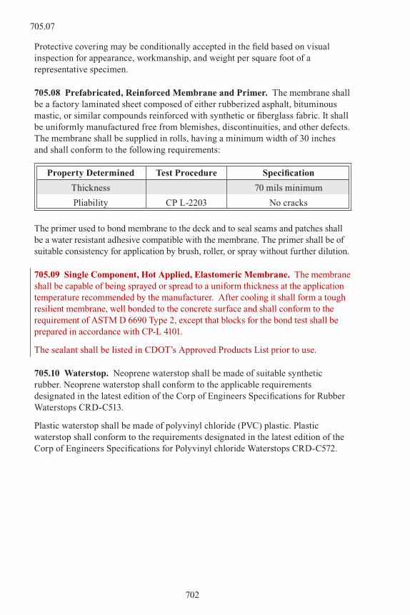
Protective covering may be conditionally accepted in the field based on visual inspection for appearance, workmanship, and weight per square foot of a representative specimen.
705.08 Prefabricated, Reinforced Membrane and Primer. The membrane shall be a factory laminated sheet composed of either rubberized asphalt, bituminous mastic, or similar compounds reinforced with synthetic or fiberglass fabric. It shall be uniformly manufactured free from blemishes, discontinuities, and other defects. The membrane shall be supplied in rolls, having a minimum width of 30 inches and shall conform to the following requirements:
Property Determined Test Procedure Specification
Thickness 70 mils minimum
Pliability CP L-2203 No cracks
The primer used to bond membrane to the deck and to seal seams and patches shall be a water resistant adhesive compatible with the membrane. The primer shall be of suitable consistency for application by brush, roller, or spray without further dilution.
705.09 Single Component, Hot Applied, Elastomeric Membrane. The membrane shall be capable of being sprayed or spread to a uniform thickness at the application temperature recommended by the manufacturer. After cooling it shall form a tough resilient membrane, well bonded to the concrete surface and shall conform to the requirement of ASTM D 6690 Type 2, except that blocks for the bond test shall be prepared in accordance with CP-L 4101.
The sealant shall be listed in CDOT’s Approved Products List prior to use.
705.10 Waterstop. Neoprene waterstop shall be made of suitable synthetic rubber. Neoprene waterstop shall conform to the applicable requirements designated in the latest edition of the Corp of Engineers Specifications for Rubber Waterstops CRD-C513.
Plastic waterstop shall be made of polyvinyl chloride (PVC) plastic. Plastic waterstop shall conform to the requirements designated in the latest edition of the Corp of Engineers Specifications for Polyvinyl chloride Waterstops CRD-C572.
702
705.07

SECTION 706CONCRETE AND CLAY PIPE
706.01 Nonreinforced Concrete Pipe. This pipe shall conform to the requirements of AASHTO M 86 for the specified diameters and strength classes.
Pipe shall be obtained from a manufacturer that is a current plant quality certified member of the American Concrete Pipe Association (ACPA), meeting all current ACPA requirements for this certification.
A copy of the ACPA certification shall be submitted to the Engineer prior to delivery of the pipe.
706.02 Reinforced Concrete Pipe. This pipe shall conform to the requirements of AASHTO M 170 for the specified diameters and strength classes. Unless otherwise specified, pipe wall design and use of elliptical reinforcement in circular pipe are optional. Reinforced concrete pipe being jacked shall be Class V and shall be furnished with grouting nipples spaced not more than 8 feet apart. Joints for this pipe shall come equipped with steel rings and rubber gaskets conforming to ASTM C 361 and as described in Bureau of Reclamation Specifications for Type R-2 joints.
Elliptical pipe conforming to AASHTO M 207 shall be furnished when required on the plans. Arch pipe conforming to AASHTO M 206 shall be furnished when required on the plans.
Precast reinforced concrete end sections shall have at least one line of reinforcement conforming to the requirements of AASHTO M 170 equivalent to the square inches per linear foot for elliptical reinforcement in circular pipe, Class II, Wall B.
Pipe shall be obtained from a manufacturer that is a current plant quality certified member of the American Concrete Pipe Association (ACPA), meeting all current ACPA requirements for this certification.
A copy of the ACPA certification shall be submitted to the Engineer prior to delivery of the pipe.
706.03 Perforated Concrete Pipe. This pipe shall conform to the requirements of AASHTO M 175 for the specified diameters and strength classes. Unless otherwise specified, perforations shall be Type 1.
Pipe shall be obtained from a manufacturer that is a current plant quality certified member of the American Concrete Pipe Association (ACPA), meeting all current ACPA requirements for this certification.
A copy of the ACPA certification shall be submitted to the Engineer prior to delivery of the pipe.
706.04 Drain Tile. This pipe shall conform to the requirements of AASHTO M 178 or M 179 for the specified material, diameters and quality classes.
703
706.04
706.05 Porous Concrete Pipe. This pipe shall conform to the requirements of AASHTO M 176 for the specified diameters.
Pipe shall be obtained from a manufacturer that is a current plant quality certified member of the American Concrete Pipe Association (ACPA), meeting all current ACPA requirements for this certification.
A copy of the ACPA certification shall be submitted to the Engineer prior to delivery of the pipe.
706.06 Vitrified Clay Pipe. This pipe shall conform to the requirements of AASHTO M 65 for the specified diameter and strength class.
706.07 Coated Concrete Pipe. This pipe may be reinforced or nonreinforced in accordance with the requirements shown on the plans for the designated diameters and strength classes, and in addition, shall be coated with asphalt mastic conforming to the requirements of AASHTO M 243.
Asphalt mastic shall be uniformly applied in two coats by spray or brush to the entire designated surface to be coated, to a total thickness of 50 mils. Asphalt mastic may also be applied by trowel in one coat provided the required thickness is obtained. The first coat shall be dry to touch before the second coat is applied. The second coat shall be dry to touch before any handling or backfilling operations.
The finished coat shall cover the surface to be protected evenly, without running, and without any visible holidays, bubbles, or bare spots.
704
706.05

SECTION 707METAL PIPE
707.01 Ductile Iron Pipe. This pipe shall conform to the requirements of ASTM A 716 for the specified diameters and strength classes. Unless otherwise specified either smooth, corrugated or ribbed pipe may be furnished.
707.02 Corrugated Steel Pipe and Pipe Arches. These conduits and coupling bands shall conform to the requirements of AASHTO M 36, except for the following:
Sawed ends and butt welded joints will be permitted for pipe with helical corrugations formed with continuous lock or welded seams provided all burrs are removed from sawed ends and provided the welds are acceptable.
Pipe fabricated with resistance spot welds shall also conform to the following additional requirement: Where double welding is necessary, adjacent welds shall not be closer than two spot weld nugget diameters from center to center.
Shop formed elliptical pipe shall be furnished where specified. Field elongation will be accepted as an alternate to shop elongation when done in a neat workmanlike manner.
Special fittings and elbows for these conduits shall be the same metal thickness as the conduit to which they are joined, and shall conform to the applicable requirements of AASHTO M 36.
Semicircular corrugated steel pipe for encasement, along with required fastening devices, shall conform to the requirements of this subsection and the requirements of Military Specification MIL-P-236, Type I or II, Class 1.
Coupling bands shall conform to the requirements of AASHTO M 36 with the following exceptions:
(1) The use of channel bands as described in 9.1 of AASHTO M 36 will not be allowed.
(2) Connecting bands shall be at least 10 ½ inches wide.
707.03 Bituminous Coated Corrugated Steel Pipe and Pipe Arches. Conduit, fittings, elbows, end sections and coupling bands shall be fully coated with bituminous material conforming to the requirements of AASHTO M 190, Type A coating or materials conforming to the requirements of AASHTO M 243, except that the use of tar base material will not be permitted. Coatings shall be shop applied. The finished coat shall uniformly cover the surface to be protected. The coating shall not contain any visible holidays, bubbles or bare spots. Minimum thickness shall be 1.3 mm (50 mils) measured on the crest of the corrugations.
In complying with AASHTO M 190, each section shall be given a double dip application. In the first immersion, the section shall remain submerged until the metal has reached a temperature that will allow the hot bituminous material to penetrate and seal each joint.
705
707.03

Other coatings meeting the requirements of AASHTO M 190 or M 243 will be acceptable upon written approval by the Engineer.
Materials meeting the requirements of AASHTO M 243 shall be uniformly applied by spray, trowel, or brush to the entire designated surface to be coated, to a minimum thickness of 1.3 mm (50 mils). The coating shall be dry to the touch prior to any handling or backfilling operations.
Special fittings and elbows for conduits shall be of the same gage as the conduit to which they are joined.
When aramid fiber bonded corrugated steel pipe is specified the pipe shall conform to ASTM A 885 and the bituminous coating shall conform to the requirements of AASHTO M 190, Type A.
707.04 Corrugated Steel Pipe for Underdrains. This pipe shall conform to the requirements of AASHTO M 36, Type I, except that all reference to “sleeve type coupler” or “coupling” as described in 9.1 and 9.2 therein shall be disregarded. Sleeve type couplers or couplings will not be permitted.
Perforated pipe shall have Class 1 perforations.
707.05 Bituminous Coated Corrugated Steel Pipe for Underdrains. This pipe shall conform to the requirements of AASHTO M 36, Type I.
Perforated pipe shall have Class 1 perforations.
Underdrain, fittings, elbows, end sections, and coupling bands shall be fully coated with bituminous material conforming to the requirements of AASHTO M 190, Type A coating or materials conforming to the requirements of AASHTO M 243, except that the use of tar base material will not be permitted. Coatings shall be shop applied. The finished coat shall uniformly cover the surface to be protected. The coating shall not contain any visible holidays, bubbles or bare spots. Minimum thickness shall be 1.3 mm (50 mils) measured on the crest of the corrugations.
In complying with AASHTO M 190, each section shall be given a double dip application. In the first immersion, the section shall remain submerged until the metal has reached a temperature that will allow the hot bituminous material to penetrate and seal each joint.
Other coatings meeting the requirements of AASHTO M 190 or M 243 will be acceptable upon written approval by the Engineer.
Materials meeting the requirements of AASHTO M 243 shall be uniformly applied by spray, trowel, or brush to the entire designated surface to be coated, to a minimum thickness of 1.3 mm (50 mils). The coating shall be dry to the touch prior to any handling or backfilling operations.
Special fittings and elbows for underdrains shall be of the same gage as the conduit to which they are joined.
The specified minimum size of perforations shall apply after coating.
706
707.03

707.06 Corrugated Aluminum Pipe. This pipe and coupling bands shall conform to the requirements of AASHTO M196, Type 1 pipe.
707.07 Corrugated Aluminum Pipe for Underdrains. This pipe shall conform to the requirements of AASHTO M196. Non-perforated pipe shall be Type 1. Perforated pipe shall be Type III, with Class I perforations.
707.08 Extensions. Connecting bands and extensions to existing culverts shall be of the same type metal or alloy, unless otherwise shown on the plans.
707.09 Repair of Damaged Coating. Units on which the spelter coating has been damaged shall be either regalvanized as provided under AASHTO M 36 or painted with one full brush coat of a zinc rich paint meeting Military Specification DOD-P-21035A, or by other approved process on properly cleaned surface, as determined by the Engineer.
Bituminous coated material which has been damaged shall be repaired with field-applied asphalt mastic conforming to AASHTO M 243. Other coating material may be used when approved by the Engineer.
707.10 Polymer Precoated Corrugated Steel Pipe. Polymer precoated corrugated steel pipe shall conform to the requirements of AASHTO M 245.
707
707.10

SECTION 708PAINTS
708.01 General. This specification covers ready-mixed paints and coatings. Paints and coatings shall be manufactured eight weeks or less prior to delivery to the project. Each paint container shall be labeled with the name and address of the manufacturer, trade name or trademark, type of paint, number of gallons, batch number, and date of manufacture.
Paints shall be free of foreign material that is capable of clogging screens, valves, pumps, and other parts of the application equipment. Paint shall not contain the following:
(1) Benzene
(2) Chlorinated solvents
(3) Ethylene glycol ethers
(4) Ethylene glycol acetates
(5) Lead
(6) Mercury
(7) Chromium
(8) Cadmium
(9) Petroleum products
The Contractor shall obtain certification in writing from the manufacturer showing that the product is free of the materials described above and that it meets or exceeds the requirements of 29 CFR 1910.1200.
Paints shall not form a surface skin within 48 hours in three-quarter filled, tightly closed containers. Paint and coating pigments shall be lead free, and shall not thicken, become granular, or curdle in their containers.
Volatile Organic Compound (VOC) levels for paints and coatings shall comply with the most current EPA regulations. All product compositional proportions are specified by weight. Material Safety Data Sheets and manufacturer’s recommended application instruction sheets representing each paint and coating shall be submitted to the Engineer for the project records prior to use.
708.02 List of Paints.
PAINTS SPECIFICATION
Structural Steel Bridge Paint Subsection 708.03
White Wood Primer TT-P-25
Outside White Paint TT-P-102, Class A
Exterior Black Paint TT-P-61
Black or White Baking Enamel TT-E-489, Class B
708
708.01
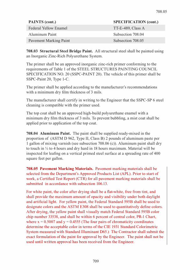
PAINTS (cont.) SPECIFICATION (cont.)
Federal Yellow Enamel TT-E-489, Class A
Aluminum Paint Subsection 708.04
Pavement Marking Paint Subsection 708.05
708.03 Structural Steel Bridge Paint. All structural steel shall be painted using an Inorganic Zinc-Rich Polyurethane System.
The primer shall be an approved inorganic zinc-rich primer conforming to the requirements of Table 1 of the STEEL STRUCTURES PAINTING COUNCIL SPECIFICATION NO. 20 (SSPC-PAINT 20). The vehicle of this primer shall be SSPC-Paint 20, Type 1-C.
The primer shall be applied according to the manufacturer’s recommendations with a minimum dry film thickness of 3 mils.
The manufacturer shall certify in writing to the Engineer that the SSPC-SP 6 steel cleaning is compatible with the primer used.
The top coat shall be an approved high-build polyurethane enamel with a minimum dry film thickness of 3 mils. To prevent bubbling, a mist coat shall be applied prior to application of the top coat.
708.04 Aluminum Paint. The paint shall be supplied ready-mixed in the proportion of (ASTM D 962, Type II, Class B) 2 pounds of aluminum paste per 1 gallon of mixing varnish (see subsection 708.06 (c)). Aluminum paint shall dry to touch in ½ to 4 hours and dry hard in 18 hours maximum. Material will be inspected for leafing on a vertical primed steel surface at a spreading rate of 400 square feet per gallon.
708.05 Pavement Marking Materials. Pavement marking materials shall be selected from the Department’s Approved Products List (APL). Prior to start of work, a Certified Test Report (CTR) for all pavement marking materials shall be submitted in accordance with subsection 106.13.
For white paint, the color after drying shall be a flat-white, free from tint, and shall provide the maximum amount of opacity and visibility under both daylight and artificial light. For yellow paint, the Federal Standard 595B shall be used to designate colors and the ASTM E308 shall be used to quantitatively define colors. After drying, the yellow paint shall visually match Federal Standard 595B color chip number 33538, and shall be within 6 percent of central color, PR-1 Chart, where x = 0.5007 and y = 0.4555 (The four pairs of chromaticity coordinates determine the acceptable color in terms of the CIE 1931 Standard Colorimetric System measured with Standard Illuminant D65.) The Contractor shall submit the exact formulation of the paint for approval by the Engineer. The paint shall not be used until written approval has been received from the Engineer.
709
708.05

(a) Low VOC Solvent Base Paint. Low VOC Paint shall be ready mixed, and shall be capable of being applied to Asphalt or Portland Cement Concrete Pavements.
(b) Acrylic Waterborne Paint. Acrylic waterborne paint shall be a lead-free, 100 percent Acrylic resin polymer waterborne product. The finished product shall maintain its consistency during application at temperatures compatible with conventional equipment.
Waterborne paint shall meet all of the following requirements:
Performance Requirements: The paint shall be water resistant and shall show no softening, blistering or loss in gloss.
Table 708-1
ACRYLIC WATERBORNE PAINT
Property Minimum Maximum Test Method
Composition Requirements
Nonvolatile portion of vehicle (white and yellow), %
43.0FTMS 141C - Method 4031 or Method 4053.1
Pigment Composition
(white and yellow), % by weight ♦
58.0 62.0ASTM D 4451ASTM D 3723
White Paint Titanium Dioxide Content,% 80 ASTM D 476, Type III
Total Carbonate,% 94 ASTM D 1199, Type GC
Yellow PaintTitanium Dioxide Content,% 80 ASTM D 476, Type III
Total Carbonate,% 94ASTM D 1199,
Type GC
Organic Yellow Pigments,% 5.0
Yellow Iron Oxide, % 83 ASTM D 768
Properties of the Finished Paint
Total Non-volatiles, (solids) % by weight
White Paint, % 77.0FTMS 141C - Method
4053.1,
Yellow Paint, % 76.0ASTM D 2369, or
ASTM D 4758
Density, lbs/gal ■
White Paint 14.0ASTM D 1475 using U.S. Standard weight
per gallon cup as defined in U.S. Military
Standard 4566AYellow Paint 13.7
Table 708-1 continues on following page.
710
708.05
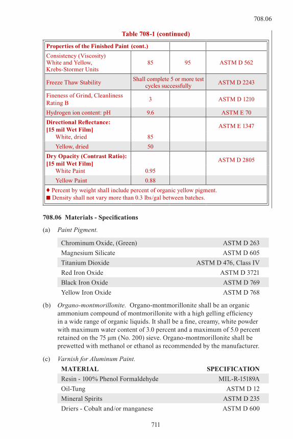
Table 708-1 (continued)
Properties of the Finished Paint (cont.)
Consistency (Viscosity) White and Yellow, Krebs-Stormer Units
85 95 ASTM D 562
Freeze Thaw StabilityShall complete 5 or more test
cycles successfullyASTM D 2243
Fineness of Grind, Cleanliness Rating B
3 ASTM D 1210
Hydrogen ion content: pH 9.6 ASTM E 70
Directional Reflectance: [15 mil Wet Film]
ASTM E 1347
White, dried 85
Yellow, dried 50
Dry Opacity (Contrast Ratio): [15 mil Wet Film]
ASTM D 2805
White Paint 0.95
Yellow Paint 0.88
♦ Percent by weight shall include percent of organic yellow pigment.■ Density shall not vary more than 0.3 lbs/gal between batches.
708.06 Materials - Specifications
(a) Paint Pigment.
Chrominum Oxide, (Green) ASTM D 263
Magnesium Silicate ASTM D 605
Titanium Dioxide ASTM D 476, Class IV
Red Iron Oxide ASTM D 3721
Black Iron Oxide ASTM D 769
Yellow Iron Oxide ASTM D 768
(b) Organo-montmorillonite. Organo-montmorillonite shall be an organic ammonium compound of montmorillonite with a high gelling efficiency in a wide range of organic liquids. It shall be a fine, creamy, white powder with maximum water content of 3.0 percent and a maximum of 5.0 percent retained on the 75 µm (No. 200) sieve. Organo-montmorillonite shall be prewetted with methanol or ethanol as recommended by the manufacturer.
(c) Varnish for Aluminum Paint.
MATERIAL SPECIFICATION
Resin - 100% Phenol Formaldehyde MIL-R-15189A
Oil-Tung ASTM D 12
Mineral Spirits ASTM D 235
Driers - Cobalt and/or manganese ASTM D 600
711
708.06

PROPERTIES OF VARNISH
Viscosity (G-H) A-C
Oil Length 275 liters per 100 kilograms of resin (33 gal.)
Nonvolatile 55% min.
Proportion of Thinners 90% Mineral Spirits, 10% Xylene
Color (Hellige) 12 max.
Zinc Reactivity None
Kauri Reduction 140% min.
Rosin and Rosin Derivatives None
Appearance Clear and Transparent
Drying Time: Set to Touch 1 to 3 hrs.
Dry Hard 18 hrs. max.
Alkali Resistance. No visible attack to film dried 72 hours after 8 hours in 5% sodium hydroxide solution at 21 °C (70 °F).
708.07 Pavement Primers. The type and application rate of epoxy resin primer shall be as recommended by the thermoplastic or preformed plastic pavement marking manufacturer.
A primer application rate of zero will not be accepted, except for thermoplastic marking and inlaid preformed plastic pavement marking placed on new asphalt surfaces as recommended by the manufacturer and approved in writing by the Engineer. However, if the Engineer determines that a new asphalt surface has become soiled, prior to placement of the pavement markings, pavement primer will be required and shall be applied as approved.
The epoxy resin primer material may be accepted at the job site on the basis of a manufacturer’s certification, or a sample may be sent to the Laboratory for testing, in which case three weeks shall be allowed between sampling and intended use.
708.08 Structural Concrete Coating. The Coating shall be a one-component, high-build, non-vapor barrier, 100 percent acrylic emulsion in water, and a texturing agent.
MINIMUM PHYSICAL PROPERTIES
Solids by Weight 48 percent (Without texturing agent)
Solids by Volume 36 percent (Without texturing agent)
Weight per gallon 8.3 lbs./gal. (Without texturing agent)
Texturing Agent 3.2 to 3.8 lbs./gal.), No. 40 to 60 Ottawa sand or equivalent
712
708.06

All coating material shall be delivered to the project site in sealed containers bearing the manufacturer’s original labels.
A material safety data sheet (MSDS) prepared in accordance with Federal Standard 313 and a complete set of manufacturer’s mixing and application instructions shall be submitted to the Engineer before the Contractor begins applying the coating.
708.09 Inspection and Testing. The manufacturer shall notify the Engineer well in advance of actual paint manufacture in order to arrange for sampling and testing of raw materials and inspection of paint production.
Test methods shall be according to ASTM or, if not covered therein, Federal Test Method Standard No. 141.
All paint shall have been approved before delivery.
713
708.09
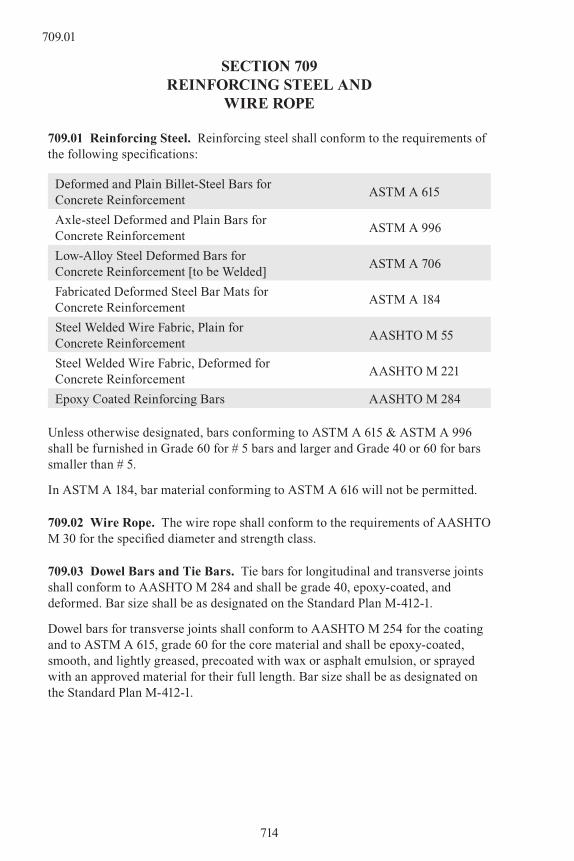
SECTION 709REINFORCING STEEL AND
WIRE ROPE
709.01 Reinforcing Steel. Reinforcing steel shall conform to the requirements of the following specifications:
Deformed and Plain Billet-Steel Bars for Concrete Reinforcement
ASTM A 615
Axle-steel Deformed and Plain Bars for Concrete Reinforcement
ASTM A 996
Low-Alloy Steel Deformed Bars for Concrete Reinforcement [to be Welded]
ASTM A 706
Fabricated Deformed Steel Bar Mats for Concrete Reinforcement
ASTM A 184
Steel Welded Wire Fabric, Plain for Concrete Reinforcement
AASHTO M 55
Steel Welded Wire Fabric, Deformed for Concrete Reinforcement
AASHTO M 221
Epoxy Coated Reinforcing Bars AASHTO M 284
Unless otherwise designated, bars conforming to ASTM A 615 & ASTM A 996 shall be furnished in Grade 60 for # 5 bars and larger and Grade 40 or 60 for bars smaller than # 5.
In ASTM A 184, bar material conforming to ASTM A 616 will not be permitted.
709.02 Wire Rope. The wire rope shall conform to the requirements of AASHTO M 30 for the specified diameter and strength class.
709.03 Dowel Bars and Tie Bars. Tie bars for longitudinal and transverse joints shall conform to AASHTO M 284 and shall be grade 40, epoxy-coated, and deformed. Bar size shall be as designated on the Standard Plan M-412-1.
Dowel bars for transverse joints shall conform to AASHTO M 254 for the coating and to ASTM A 615, grade 60 for the core material and shall be epoxy-coated, smooth, and lightly greased, precoated with wax or asphalt emulsion, or sprayed with an approved material for their full length. Bar size shall be as designated on the Standard Plan M-412-1.
714
709.01

SECTION 710FENCE AND GUARDRAIL
710.01 Barbed Wire. Steel barbed wire shall conform to the requirements of ASTM A 121, Class I. Aluminum barbed wire shall be manufactured in accordance with ASTM B 211 with alloy 5052-O for the line wire and alloy 5052-H38 for the barbs.
710.02 Woven Wire. Woven wire shall conform to the details and requirements shown on the plans and to the following:
Zinc coated steel woven wire shall conform to the requirements of ASTM A 116, coating Class I.
Aluminum coated steel woven wire shall conform to the requirements of ASTM A 116, Type A.
Fittings and attachments shall be zinc coated to conform to the requirements of AASHTO M 232.
710.03 Chain Link Fabric. Chain link fabric and required fittings and hardware shall conform to the requirements of AASHTO M 181 for the kind of metal, sizes of wire and mesh specified.
Zinc coating for steel fabric shall conform to ASTM A 392, Class I; and aluminum coating for steel fabric to ASTM A 491, Class I.
710.04 Snow Fence. Wire-bound picket fence shall conform to the requirements of ASTM F 537. Posts shall conform to the requirements of AASHTO M 281.
710.05 “W” Beam Rail. The rail elements shall be corrugated sheet steel beams conforming to the requirements of AASHTO M 180 of the designated class and type. The beams shall be galvanized, shop painted or corrosion resistant as may be specified. The same requirements shall apply to metal offset devices.
Corrosion resistant steel for rail elements and terminals shall not be painted or galvanized.
Corrosion resistant beam rails shall consist of corrugated sheet steel conforming to the requirements of AASHTO M 180, Type IV and shall have a corrosion resistance of at least 4 times that of carbon steel without copper (0.02 Max), or twice that of carbon steel with copper. The sheet steel may be either in coils or cut lengths when processed for corrugation.
All corrosion resistant material shall be sandblasted to provide a uniform weathered appearance.
All corrosion resistant steel parts shall be handled with care to avoid gouges, scratches, or dents. Care shall be exercised to keep foreign material such as paint, grease, oil, or crayon, from contact with the surface. Steel parts damaged either physically or by contact with foreign substances, will not be accepted.
715
710.05

During shipment or site storage, corrosion resistant steel parts must be positioned to allow free drainage and air circulation on the surfaces. Natural oxide formation on the steel may occur and will not be considered objectionable.
The Contractor shall furnish three copies of a certified mill test report to the Engineer. This report shall show the results of physical and chemical tests of the metal and its coating.
710.06 Timber For Wood Sound Barrier. Timber shall be any of the timber species given in subsection 508.02 including all species defined as “Native.” Throughout the project, posts shall be of one species; boards may be of another species; and rails may be a mix of any permissible species, except where single sided fence is built, the rails shall be of one species. The exposed board surfaces shall be of one finish throughout the entire fence and may be rough sawn, SIS, S1S2E, or S48; posts and rails may have any of the finishes. Species selected for posts, rails, and boards shall conform to the grading rules of the Western Wood Products Association (WWPA), the Southern Pine Inspection Bureau (SPIB), or the West Coast Lumber Inspection Bureau (WCLIB) for grading and strength.
(1) Posts. WWPA or WCLIB posts and timbers, No. 1 or better; or SPIB timbers No. 2SR or better.
(2) Rails. WWPA, WCLIB, or SPIB: Light framing, standard or better; or structural joists and planks, No. 2 or better.
(3) Boards. WWPA No. 2 common or better; or SPIB No. 1 or better.
(4) Treatment. The selected species shall be pressure treated lumber conforming in all respects to the American Wood Preserver’s Association (AWPA) standards, Sections C1 and C2 (Soil contact for posts, above ground for balance of fence). A treatment report is required from the treatment plant.
(5) Preservative. Section P5 of AWPA standards.
All lumber shall be manufactured in accordance with Product Standard 20-70 as published by the Department of Commerce, and shall be grade marked by a grading agency or have an accompanying certificate from the grading agency. The grading agency shall be certified by the Board of Review of the American Lumber Standards Committee.
All posts, rails, and fence board materials shall be dried after treatment to a maximum of 19 percent moisture content.
710.07 Fence Posts. Wood posts shall conform to the details and dimensions indicated on the plans. Wood posts shall be straight, sound, and seasoned with ends sawed off square or as indicated. All knots shall be trimmed flush with the surface. Wood posts shall be peeled and shall be treated with preservative in accordance with AASHTO M 133 and AWPA C14. When native cedar posts are called for on the plans, the requirements for peeling and for treating may be omitted.
716
710.05

All dimension timber and lumber required for fences or gates shall be sound, straight, and free from knots, splits, and shakes. It shall be of the species and grades indicated on the plans.
Concrete posts shall be made of concrete of the class specified, and shall contain steel reinforcement as shown on the plans.
Steel posts shall be galvanized in accordance with AASHTO M 111. Fittings, hardware and other appurtenances not specifically covered by the Contract shall be standard commercial grade, and in accord with current standard practice. Pipe material for fence posts shall conform to the requirements shown on the plans and to the requirements of Class 1 Pipe, Grade A or Grade B, of Federal Specification RR-F-191/3C.
710.08 Guardrail Posts. Posts shall be of either wood or steel. When the choice of post is at the option of the Contractor, there shall be only one kind furnished on the project unless otherwise specified in the Contract.
(a) Wood posts shall be fabricated from an approved or specified timber species and shall be of the quality, diameter or section, and length as specified or as shown in the Contract. Treated posts shall be fabricated or framed before treatment, and shall conform to the requirements of AASHTO M 133.
(b) Steel posts shall be of the section and length as specified or as shown in the Contract. Steel shall conform to the requirements of AASHTO M 183 for the grade specified.
The posts shall be galvanized or corrosion resistant as may be specified.
All corrosion resistant material shall conform to the requirements of AASHTO M 222.
(c) Concrete deadmen for end anchorages shall be as specified in the Contract.
710.09 Guardrail Hardware. Splices, end connections, end anchor rods, and accessories shall be as specified or as shown in the Contract.
Bolts, nuts, and washers shall be galvanized in accordance with AASHTO M 232, Class C, or AASHTO M 298, Class 50, Type 1. All other fittings shall be galvanized in accordance with AASHTO M 111. Bolts, nuts, and washers for corrosion resistant guard rail shall be of corrosion resistant material and conform to or exceed the requirements of ASTM A 307.
Where high strength bolts are required, they shall conform to the requirements of ASTM A 325.
717
710.09
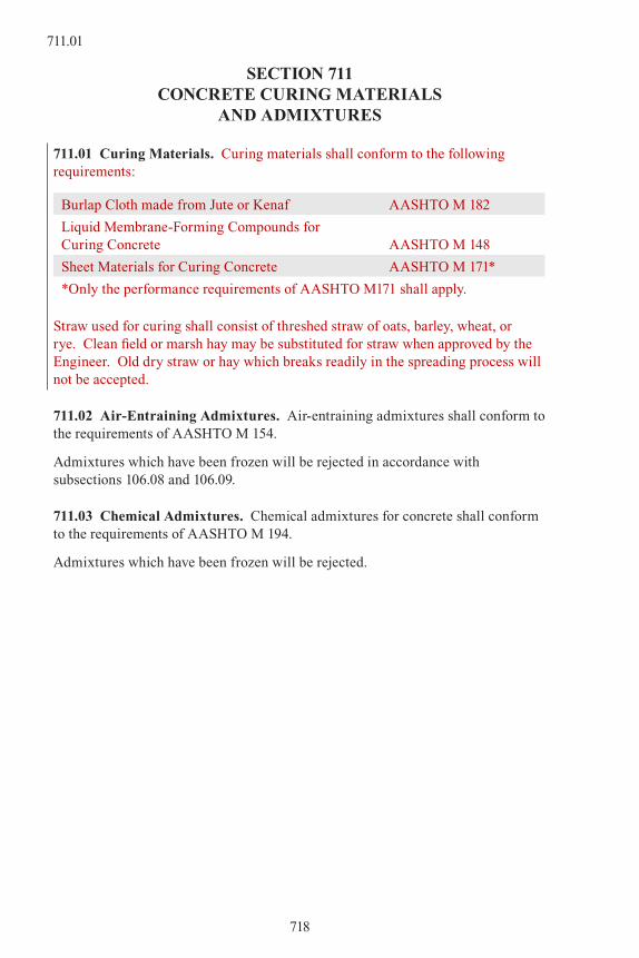
SECTION 711CONCRETE CURING MATERIALS
AND ADMIxTURES
711.01 Curing Materials. Curing materials shall conform to the following requirements:
Burlap Cloth made from Jute or Kenaf AASHTO M 182
Liquid Membrane-Forming Compounds for Curing Concrete AASHTO M 148
Sheet Materials for Curing Concrete AASHTO M 171*
*Only the performance requirements of AASHTO M171 shall apply.
Straw used for curing shall consist of threshed straw of oats, barley, wheat, or rye. Clean field or marsh hay may be substituted for straw when approved by the Engineer. Old dry straw or hay which breaks readily in the spreading process will not be accepted.
711.02 Air-Entraining Admixtures. Air-entraining admixtures shall conform to the requirements of AASHTO M 154.
Admixtures which have been frozen will be rejected in accordance with subsections 106.08 and 106.09.
711.03 Chemical Admixtures. Chemical admixtures for concrete shall conform to the requirements of AASHTO M 194.
Admixtures which have been frozen will be rejected.
718
711.01

SECTION 712MISCELLANEOUS
712.01 Water. Water used in mixing or curing shall be reasonably clean and free of oil, salt, acid, alkali, sugar, vegetable, or other substance injurious to the finished product. Water will be tested in accordance with, and shall meet the suggested requirements of AASHTO T 26. Water known to be of potable quality may be used without test. Where the source of water is relatively shallow, the intake shall be so enclosed as to exclude silt, mud, grass, or other foreign materials.
712.02 Calcium Chloride. Calcium chloride shall conform to the requirements of AASHTO M 144.
712.03 Hydrated Lime. The hydrated lime for Hot Mix Asphalt (HMA) shall conform to the requirements of AASHTO M 303, Type I. In addition, the particle size requirements shall conform to AASHTO M 303 when tested in accordance with CP-L 4209 Physical Testing of Quicklime, Hydrated Lime, and Limestone.
712.04 (unused)
712.05 Precast Concrete Units. Precast concrete manhole base sections, riser sections, and grade rings shall conform to AASHTO M 199. All other precast units shall be cast in substantial forms. Structural concrete used shall attain a minimum 28-day compressive strength of 3000 psi as determined in accordance with AASHTO T 22. When air-entrained concrete is specified, it shall have an air content of 5 to 8 percent by volume. The precast units shall be cured in accordance with AASHTO M 170. Additional reinforcement shall be provided as necessary to provide for handling of the precast units.
A sufficient number of cylinders shall be cast and field cured from each batch, or truck-mixer load, of concrete to permit compression tests at 7, 14, and 28 days, and to allow for at least two cylinders for each test. When the strength requirement is met the units will be certified for use.
Cracks in units, honeycombed or patched areas in excess of 30 square inches, excessive water absorption, or failure to meet strength requirements will be cause for rejection.
712.06 Frames, Grates, Covers, and Steps. Metal units shall conform to the plan dimensions and to the following specification requirements for the designated materials.
Gray iron castings shall conform to the requirements of AASHTO M 306 and AASHTO M 105, Class 35B.
Carbon-steel castings shall conform to the requirements of AASHTO M 103, grade 415-205, Class 2.
719
712.06

Ductile iron castings shall conform to the requirements of ASTM A 536. Grade shall be optional unless otherwise designated.
Structural steel shall conform to the requirements of AASHTO M 270.
Malleable iron castings shall conform to the requirements of ASTM A 47. Grade shall be optional unless otherwise designated.
Steps shall conform to the requirements of AASHTO M 199.
Galvanizing, where specified for these units shall conform to the requirements of AASHTO M 111.
712.07 Geosynthetics. Geosynthetic rolls shall be furnished with suitable wrapping to protect against moisture and extended ultraviolet exposure prior to placement. Each roll shall be labeled to provide product identification sufficient for inventory and quality control purposes. Rolls shall be stored in a manner which protects them from the elements. If stored outdoors, they shall be elevated and protected with a waterproof cover. The Contractor shall submit a certified test report from the manufacturer in accordance with subsection 106.13 including all data necessary to verify compliance with this specification.
Securing pins shall be made from galvanized steel wire or other approved wire material, 0.091 inch or larger in diameter. They shall be U-shaped, with legs 6 inches long and a 1 inch crown.
Physical requirements of geosynthetics shall meet or exceed what is shown in Table 712-1. Unless otherwise stated, all property values represent minimum average roll values (MARV) in the weakest principle direction. Stated values are for non-critical, non-severe conditions. Lots shall be sampled in accordance with ASTM D 4354.
(a) Geomembrane. Geomembrane shall be manufactured for stopping seepage loss. The lining shall consist of virgin polyvinyl chloride (PVC) resins, plasticizers, stabilizers, and other necessary materials that, when compounded, shall meet or exceed the physical requirements for the thickness specified in Table 712-1.
Individual widths of PVC materials shall be fabricated into large sections by dielectric sealing into a single piece, or into a minimum number of panels, up to 100 feet wide, as required to fit the facility. Lap joints with a minimum joint width of ½ inch shall be used. After fabrication, the lining shall be accordion folded in both directions and packaged for minimum handling in the field. Shipping boxes shall be substantial enough to prevent damage to contents.
720
712.06

Table 712-1
PHYSICAL REQUIREMENTS FOR GEOMEMBRANE
Property
Thickness
Test Method0.25 mm(10 mil)
0.51 mm(20 mil)
0.76 mm(30 mil)
Thickness, % Tolerance ±7 ±5 ±5 ASTM D 1593
Tensile Strength, kN/m (lbs./in.) width
3.50 (20) 8.75 (50) 12.25 (70)ASTM D 882, Method B
Modulus @ 100% Elongation, kN/m (lbs./in.)
1.58 (9) 3.50 (20) 5.25 (30)ASTM D 882, Method B
Ultimate Elongation, % 350 350 350ASTM D 882, Method A
Tear Resistance: N (lbs) 18 (3.2) 29 (6.5) 38 (8.5) ASTM D 1004
Low Temperature Impact, °C (°F)
-23 (-13) -26 (-15) -29 (-20) ASTM D 1790
Volatile loss, % max. 1.5 0.9 0.7ASTM D 1203, Method A
Pinholes, No. /8 m2
(No. Per 10 sq. Yds.) max.1 1 1
Bonded Seam Strength, % of tensile strength
80 80 80
(b) Reserved.
712.08 Geotextiles. Geotextile rolls shall be furnished with suitable wrapping to protect against moisture and extended ultraviolet exposure prior to placement. Each roll shall be labeled to provide product identification sufficient for inventory and quality control purposes. Rolls shall be stored in a manner which protects them from the elements. If stored outdoors, they shall be elevated and protected with a waterproof cover. The Contractor shall submit a certified test report from the manufacturer in accordance with subsection 106.13 including all data necessary to verify compliance with this specification.
Securing pins shall be made from galvanized steel wire or other approved wire material, 0.091 inch or larger in diameter. They shall be U-shaped, with legs 6 inches long and a 1 inch crown.
Physical requirements for all geotextiles shall conform to the requirements of AASHTO M-288. Materials shall be selected from the New York Department of Transportation’s Approved Products List of Geosynthetic materials that meet the National Transportation Product Evaluation Program (NTPEP) and AASHTO M-288 testing requirements. The current list of products that meet these requirements is located at: www.dot.state.ny.us
The Geotextile Approved Products List may be accessed by clicking on the following tabs once on the NYDOT site to:
721
712.08

(1) Publications
(2) more
(3) site index tab
(4) approved list of Materials & Equipment
(5) geosynthetics for Highway Construction
(6) geotextiles
Table 712-2
TYPICAL VALUES OF PERMEABILITY COEFFICIENTS1
Turbulent Flow
ParticleSize Range
Millimeters (inches)
EffectiveSize Permeability
Coefficient kcm/s
D max D minD 20 mm (inches)
Derrick STONE 3000 (120) 900 (36) 1200 (48) 100
One-man STONE 300 (12) 100 (4) 150 (6) 30
Clean, fine to coarse GRAVEL
80 (3) 10 (¼) 13 (½) 10
Fine, uniform GRAVEL 8 (3/8) 1.5 (1/16) 3 (1/8) 5
Very coarse, clean,
uniform SAND3 (1/8) 0.8 (1/32) 1.5 (1/16) 3
Uniform, coarse SAND 2 (1/8) 0.5 (1/64) 0.6 0.4
Uniform, medium SAND 0.5 0.25 0.3 0.1
Clean, well-graded SAND & GRAVEL
10 0.05 0.1 0.01
Uniform, fine SAND 0.25 0.05 0.06 40 x 10-4
Well-graded, silty
SAND & GRAVEL5 0.01 0.02 4 x 10⁻⁴
Silty SAND 2 0.005 0.01 1.0 x 10⁻⁴
Uniform SILT 0.05 0.005 0.006 0.5 x 10⁻⁴
Sandy CLAY 1.0 0.001 0.002 0.05 x 10⁻⁴
Silty CLAY 0.05 0.001 0.0015 0.01 x 10⁻⁴
CLAY (30% to 50% clay sizes)
0.05 0.0005 0.0008 0.001 x 10⁻⁴
Colloidal CLAY (-2 µm 50%)
0.01 10 40 10-9
1 Basic Soils Engineering, R.K. Hough, 2nd Edition, Ronald Pess Co.; 1969, Page 76.
Note: Since the permeability coefficient of the soil will be unknown in most non-crit-ical, non-severe applications for erosion control and drainage, the soil-permea-bility coefficients listed in Table 712-2 may be used as a guide for comparing the permeability coefficient of the fabric with that of the in-place soil
722
712.08
712.09 Gabions and Slope Mattresses. All wire used in the manufacture and assembly of the mesh shall conform to Federal Specification QQ-W-461H, finish 5, class 3.
Wire mesh for Gabions (cage thickness 12 inches and greater) shall be 11 gage (U.S.), soft temper.
Wire mesh for Slope Mattress (cage thickness up to 10 inches) shall be 14 gage (U.S.), soft temper.
Samples for testing shall include at least one sample of each component of the mesh.
Tie and connecting wire shall be supplied for securely fastening all edges of the gabions and diaphragms. Gabions shall be provided with four cross connecting wires in each cell ½ unit high and eight in each cell one unit high. Gabions shall also have inner tie wires connecting the front face to the rear face at approximate spacing of 12 inches in both vertical and horizontal dimensions. Tie wire shall meet the same specifications for wire used in the mesh except that tie wire for gabion cages shall not be more than two gages lighter.
All wire used, including tie and connecting wire, shall be certified by mill test reports showing compliance with specification requirements.
(a) Mesh Opening. The longer dimension of the mesh openings for gabions and slope mattresses shall be as shown on the plans.
(b) Wire Mesh. Wire mesh shall be woven in such a manner as to be non-raveling and have elasticity. Tests for compliance with these and the following properties shall be performed by the Contractor. A certified test report, showing these required results and information shall be supplied with each project. Tests are to be run on cages of the same specification, made within a year prior to the date of letting.
(c) Non-raveling. The mesh for both gabions and slope mattresses shall show no raveling beyond the mesh opening in which the break occurred when the loading is continued after the first break in the test conducted with the pull parallel to the axis of the wire twist.
(d) Elasticity. For gabions, when pulled parallel to the axis of the wire twist and deformation is controlled by spreader bars, no wire shall break until the mesh has been stretched at least 4.5 percent. The pull test shall be performed both parallel and perpendicular to the axis of the wire twist and in either case, the first wire break shall not occur until the loading on the table below has been reached.
(e) Edge Wire Connection. The edge wire connection for both gabions and slope mattresses shall be strong enough so that when tested the first wire break shall occur in the wire mesh.
(f) Selvedge. The selvedge on each sheet of mesh for both gabions and slope mattresses shall be galvanized steel wire (as described above) two gages
723
712.09
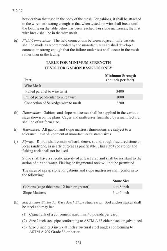
heavier than that used in the body of the mesh. For gabions, it shall be attached to the wire mesh strong enough so that when tested, no wire shall break until the loading on the table below has been reached. For slope mattresses, the first wire break shall be in the wire mesh.
(g) Field Connections. The field connections between adjacent wire baskets shall be made as recommended by the manufacturer and shall develop a connection strong enough that the failure under test shall occur in the mesh rather than in the lacing.
TABLE FOR MINIMUM STRENGTH
TESTS FOR GABION BASKETS ONLY
Part Minimum Strength
(pounds per foot)
Wire Mesh
Pulled parallel to wire twist 3400
Pulled perpendicular to wire twist 1000
Connection of Selvedge wire to mesh 2200
(h) Dimensions. Gabions and slope mattresses shall be supplied in the various sizes shown on the plans. Cages and mattresses furnished by a manufacturer shall be of uniform size.
(i) Tolerances. All gabion and slope mattress dimensions are subject to a tolerance limit of 3 percent of manufacturer’s stated sizes.
(j) Riprap. Riprap shall consist of hard, dense, sound, rough fractured stone or local sandstone, as nearly cubical as practicable. Thin slab type stones and flaking rock shall not be used.
Stone shall have a specific gravity of at least 2.25 and shall be resistant to the action of air and water. Flaking or fragmental rock will not be permitted.
The sizes of riprap stone for gabions and slope mattresses shall conform to the following:
Stone Size
Gabions (cage thickness 12 inch or greater) 4 to 8 inch
Slope Mattress 3 to 6 inch
(k) Soil Anchor Stakes for Wire Mesh Slope Mattresses. Soil anchor stakes shall be steel and may be:
(1) Crane rails of a convenient size, min. 40 pounds per yard.
(2) Size 2 inch steel pipe conforming to ASTM A 53 either black or galvanized.
(3) Size 3 inch x 3 inch x 3/8 inch structural steel angles conforming to ASTM A 709 Grade 36 or better.
724
712.09

(4) Used rails, pipe or angles may be used provided the material is not rusted or damaged to such an extent that the strength of the stakes is affected.
Soil anchor stakes shall be of the lengths called for on the plans.
712.10 Epoxy. Epoxy used for bonding new, or wet concrete, to old concrete shall be an approved product and shall be of the type specifically intended for bonding wet concrete to existing concrete. Each container of epoxy shall conform to ASTM C 881.
712.11 Plastic Pipe for Underdrains. Polyethylene perforated or nonperforated corrugated pipe shall conform to AASHTO M 252.
Perforated or nonperforated Polyvinyl Chloride Pipe-Smooth Interior, Smooth or Ribbed Exterior, shall conform to AASHTO M 304.
712.12 Geocomposite Drains. Geocomposite drains, underdrains, and edge drains for subsurface drainage shall be constructed of a drainage geotextile and a semi-rigid drainage core. A drainage pipe collector may also be included in the drain system.
Drainage geotextile shall be a minimum Class 3, conforming to AASHTO M 288. The drainage pipe collector, when used, shall conform to the requirements designated in subsection 605.02 for the type of pipe used.
The semi-rigid drainage core shall be constructed of material that will not deteriorate in subsurface conditions, and shall conform to the physical requirements of Table 712-3.
Table 712-3
PHYSICAL REQUIREMENTS FOR DRAINAGE CORE
Property Value Test Method
Compressive Strength, kPa (lbs./sq. in.) 140 (20) ASTM D 1621
In-Plane Flow Capacity L/s/m (gal./min./ft.), minimum
2.12 (10) ASTM D 4716
Minimum Core Thickness, mm (inch) 6 (0.25)
712.13 Plastic Pipe. Plastic pipe shall conform to the following requirements for the type of pipe used:
(a) Polyethylene (PE) Pipe. Polyethylene (PE) pipe shall conform to the following requirements for the type of culvert pipe used:
(1) AASHTO M 252 (Corrugated Pipe) for nominal pipe sizes of 3 to 10 inches (75 to 250 mm) with the following additions or exceptions:
(i) Type S, and Type SP are acceptable. (Type C, Type CP and Type D will not be accepted.)
(ii) Rotational Molded Pipe will not be accepted.
725
712.13

(2) AASHTO M 294 (Corrugated Pipe) for nominal pipe sizes of 12 to 60 inches (300 to 1500 mm) with the following additions or exceptions:
(i) Type S, and Type SP are acceptable. (Type C, Type CP and Type D will not be accepted.)
(ii) Rotational Molded Pipe will not be accepted.
(3) ASTM F 894 (Ribbed, Profile) with the following additions or exceptions:
(i) AASHTO LRFD Bridge Design Specifications, SECTION 12, 50 year life requirements.
(ii) Minimum Cell Class per ASTM D 3350 of 334433C or 335434C.
(iii) Minimum section properties as noted in SECTION 12.
(4) ASTM F 714 (Smooth Wall) with the following additions or exceptions:
(i) A DR of 21 or less will be required.
(ii) AASHTO LRFD Bridge Design Specification, SECTION 12, 50 year life requirements.
(iii) Minimum Cell Class per ASTM D 3350 of 335434C.
The Contractor shall provide a polyethylene (PE) pipe product that is prequalified under the AASHTO National Transportation Product Evaluation Program (NTPEP). Only products from suppliers whose manufacturing plant and PE pipe products comply with this specification shall be placed by the Contractor. The current list of plants and PE pipe products that meet these requirements is located at: www.ntpep.org. The Contractor shall use plants listed as compliant and a size listed in the NTPEP reports on PE Thermoplastic Pipe. Every Certificate of Compliance (COC) on each diameter PE pipe product delivered to the project shall include a statement that the product has been manufactured at a NTPEP inspected plant, has been tested by NTPEP, has a NTPEP product number, and is currently on the NTPEP website. The COC shall confirm that the supplied pipe meets the applicable specification limits in Subsection 712.13. Manufacturers shall remain acceptable to CDOT as long as the results of verification samples and performance in the field are satisfactory. Any changes in the PE pipe formulation will require re-submittal for prequalification testing by NTPEP.
(b) Polyvinyl Chloride (PVC) Pipe
(1) AASHTO M 304 (Profile) for nominal pipe sizes of 4 to 48 inches (100 to 1200 mm).
(2) ASTM F794 (Profile) for nominal pipe sizes 4 to 48 inches with 46 psi minimum pipe stiffness.
(3) ASTM F949 (Profile) for nominal pipe sizes 4 to 36 inches with 46 psi minimum pipe stiffness.
726
712.13

SECTION 713TRAFFIC CONTROL MATERIALS
713.01 Signs-General. Aluminum or steel used for traffic control shall conform to Table 713-1.
Table 713-1
Aluminum Steel
ApplicationASTM
DesignationAlloy No. Temper
ASTM Designation
Sign panels B 209
6061-T6
5052-H36
5052-H38
*A 653
Traffic controller cabinets B 209 6061-T6A 709
Grade 36
Clip bolts B 211 2024-T4
Locknuts or steel nuts and bolts B 211 2017-T4 A 307
Clips and backing angles B 221 6061-T6
* Steel sheets shall have a Z600 zinc coating in accordance with ASTM A 653 and a light phosphate coating. Phosphate coating of 3.5 oz./sq. ft. will be required for application with reflective sheeting. Nuts and bolts shall be galvanized or cadmium plated.
713.02 Aluminum Sign Panel Tolerances. Aluminum sign panel sheet dimensional tolerances shall conform to the applicable requirements of the American National Standards Institute Dimensional Tolerances for Aluminum Products, ANSIH35.2(M), with the following exceptions:
The flatness tolerances shall be onehalf the values listed in Table 3.12, and shall apply to all aluminum alloy grades permitted for sign panels.
Sign blanks are to be tensile leveled for sheet thickness less than 0.09 inch, and stretcher leveled for thickness equal to or greater than 0.09 inch.
The individual sign blank bow tolerance (deviation of a side edge from a straight line) shall not exceed 1/3 inch, and the dimensions of the opposing sides shall be within 1/16 inch.
Aluminum sign panel shall be subject to the requirements of the first paragraph of subsection 713.09.
713.03 (unused)
713.04 Sign Panel Backgrounds. Reflective sheeting background material used shall be of the type as specified on the plans and shall conform to the requirements specified in subsection 713.10.
727
713.04
All reflective sheeting shall be sealed at the seams and edges as recommended by the manufacturer.
The aluminum sign blanks shall receive a chemical treatment conforming to ASTM B 449, Class 2 prior to placement of reflective sheeting.
713.05 Hardware. All hardware shall be compatible with sign material and shall not cause discoloration due to weather.
713.06 Messages. Letter design shall be in accordance with the following:
Letter design for commercial legend shall be Series “E” for capitals, and Series “E Modified” for upper and lower case letters and numbers. The “E Modified” legend shall have an increased stroke width of 20 percent of the required legend height. The Inter-letter spacing shall be “Colorado Improved” in accordance with the Colorado Supplement to the Standard Highway Signs.
Silk screen process figures shall be in accordance with the plans and series figures described in the current editions of “Standard Alphabets for Highway Signs” and “Standard Highway Signs”, published by the FHWA, and the “Colorado Supplement to Standard Highway Signs”.
For overhead signs, the legend and borders shall be VIP sheeting or equivalent. The background retroreflective sheeting shall be Type IV.
713.07 Reflectors. Reflectors shall consist of a clear and transparent acrylic plastic prismatic reflex lens with a smooth front face, except for the legibly molded manufacturer’s trademark, and a back hermetically sealed surface with prismatic configuration effecting total internal reflection of light. Firmly fused to the back surface shall be a backing material. The backing material shall be white opaque plastic of the same type as the lens and delineator reflectors may be backed with a plastic coated metallic foil. Delineator reflectors shall be housed in embossed aluminum and provided with a single grommetted mounting hole. The delineator unit shall withstand the combined corrosion test described in ASTM B 117.
713.08 Glass Beads for Traffic Markings. Glass beads for Traffic Paint shall conform to AASHTO M 247, Type 1 or Type 2, nonflotation grade.
Glass beads shall be furnished in fully identified containers and shall be free of extraneous material or clumps.
Glass beads used for any type of pavement marking shall not contain more than 75 parts per million (ppm) Arsenic, 75 ppm Antimony and 100 ppm Lead.
Glass beads for Thermoplastic Pavement Marking shall conform to AASHTO M 247, Type 1.
Glass beads for epoxy pavement marking shall conform to AASHTO M 247, Type 1. The beads shall be silicon treated to meet the requirements of Section 4.4.2 of AASHTO M 247.
728
713.04

Glass beads for methyl methacrylate pavement marking shall conform to AASHTO M 247, Type 1 non-floatation and shall be applied by the first bead applicator. Glass beads applied by the second bead applicator shall be AASHTO M 247, Type 1 silane coated (AC-02) flotation beads.
713.09 Sampling and Inspection. The Engineer shall be notified well in advance of beginning of shop work so that adequate arrangements may be made for sampling and inspection. Shop inspection may be waived and complete inspection made when the fabricated sign panels are delivered to the site of the work.
The following samples shall be submitted to the Engineer for approval:
(1) A 12 inch x12 inch sample of finished material for figure frames.
(2) A 12 inch x12 inch sample of reflective sheeting representing each lot used on the project.
(3) Two reflectors for each 100, or part thereof, of each size and color, with a limit of 53 samples for any one size or color. When reflective buttons are so affixed to the cutout frames that their removal for testing will cause breakage, it shall be the responsibility of the sign fabricator to furnish a representative sample of reflective buttons.
(4) 2 pounds of glass beads, representing each lot used on the project.
(5) 1 pint of paint of each color, representing each lot used on the project.
(6) 1 pound of thermoplastic marking material and one liter of each primer component.
(7) 36 inch strip of preformed plastic pavement marking.
(8) 36 inch strip of pavement marking tape.
(9) 1 square foot of preformed thermoplastic pavement marking material.
713.10 Quality Requirements of Reflective Materials. Reflective devices and reflective sheeting shall be materials which are on the Department’s Approved Products List.
(a) Reflective Devices.
1. Reflective Quality Requirements.
A. Delineator and Median Barrier Reflectors. The specific intensity of each delineator and median barrier reflector shall be at least equal to the following minimum values when tested in accordance with AASHTO T 257, with an observation angle of 0.1 degrees.
Entrance Angle Degrees
Specific IntensityCandlepower per Foot-Candle
Crystal Yellow Red Green
0 110 50 33 22
20 60 30 18 12
729
713.10

B. Cut-out Figure Reflectors. The specific brightness of crystal reflectors used in cut-out figures shall be at least equal to the following minimum values.
Observation Angle Degrees
Entrance Angle Degrees
Specific Brightness: Candlepower per Sq. In. per Foot-Candle
0.1 0 14.0
0.1 20 5.6
2. Material and Component Requirements. Plastic for delineator and cutout figure reflectors shall be poly methyl methacrylate conforming to requirements of ASTM D 788, Grade 8. The reflectors shall meet test requirements of CP L-2115, Sec. 3.2 and 3.3.
(b) Retroreflective Sheeting. Reflective sheeting for traffic control devices shall conform to the requirements of ASTM D 4956.
713.11 Traffic Signals. Electrical conduit, pull boxes and junction boxes shall conform to the requirements of Section 613 and subsection 715.06, and to the details shown on the plans.
Conductors shall be nineteen strand or seven stranded, tinned copper wire, rated at 600 volts and individually insulated with heat stabilized polyethylene. Conductors and cables shall be copper and conform to Specification 19-1 of the IMSA.
Direct-burial cable shall be copper and conform to Specification 19-5 of the IMSA except that conductors shall be seven, wire, stranded.
Pull rope shall be 1/8 inch nylon.
Messenger cable (span wire) shall be 3/8 inch diameter (minimum), seven wire stranded, common galvanized, utilities grade, rated at 11,500 pounds, in accordance with ASTM A 475.
Grounding and bonding wires, straps and electrodes shall be copper and conform to NEC Article 250.
Adjustable face vehicle traffic control signal heads and associated equipment shall conform to the general specifications and definitions contained in the latest issue of Technical Report No. 1, prepared by the ITE, and as shown on the plans.
Adjustable face pedestrian signal heads and associated equipment shall conform to the general specifications and definitions contained in the latest issue of Technical Report No. 5, prepared by the Institute of Traffic Engineers, and as shown on the plans.
Traffic signal lamps shall conform to the general specifications and definitions contained in the latest issue of Technical Report No. 6, prepared by the Institute of Traffic Engineers. Lamps shall be rated for operation at 120 volts AC. Lamp wattages shall be 60-69 Watts for all 8 inch traffic signals, 150 Watts for all 12
730
713.10

inch traffic signals, 116 Watts for all 16 inch pedestrian signals, or as otherwise specified by the manufacturer.
LED Traffic Signal Section optical units shall meet or exceed ITE Adjustable Face Vehicular Traffic Control and Pedestrian Signal Head Standards. In addition to this, LED optical units shall conform to the following requirements:
(1) Wattage
Max. 35 watts, ±5 watts for 12 inch ball
Max. 30 watts, ±5 watts for 8 inch ball
Max. 15 watts, ±5 watts for 12 inch arrow
Max. 15 watts, ±5 watts for PED hand symbol
Maximum total harmonic current distortion (THD) shall be < 20 percent.
Power factor shall be > 90 percent.
Load balance requirement: load in one phase shall not exceed the load in any other phase by 15 percent.
Note: THD and power factor requirements shall be waived for products designed to operate at less than 14 watts.
(2) Voltage
Operating shall be between 85 and 130 VAC. Electronic circuitry shall assure proper operation of the load switch and monitor in the control cabinet.
(3) Circuit Configuration
The LEDs shall be connected to form multiple series circuits. All series circuits shall be interconnected at intervals, forming subcircuits not exceeding 15 LEDs for the ball and arrow signals, and 10 LEDS for the pedestrian hand symbol. In the event of an LED failure, these subcircuits shall limit the number of extinguished LEDs to no more than 4 percent of the total on the ball and pedestrian hand signal lamps, and 6 percent of the total on the arrow lamp.
(4) Enclosure
Shall be dust and water resistant
(5) Operating Temperature
Between -40 °F and +165 °F
(6) Lens
Shall be replaceable, polycarbonate (UV stabilized “Lexan”) convex lens; meet ITE color standards; minimum of 1/8 inch thickness; and minimum light transmittance of 92 percent, free from bubbles, flaws and other imperfections. Non-polycarbonate tinted lenses will be accepted provided that these meet ITE color standards. Chromacity shall be measured uniform across the face of the lens. Non-polycarbonate lenses shall also meet 3½ foot drop tests. The outside face of the lens shall be smooth. Grooves, ridges, or both that may
731
713.11

be used to enhance optical characteristics of the LED optical unit shall be located on the inside face of the lens.
(7) Candlepower Distribution
Shall meet minimum ITE specifications. Intensity shall be measured uniform across the face of the lens. Brightness shall be maintained in the event of voltage fluctuations or voltage drops.
(8) Beam Spread
30 degrees both horizontally and vertically.
(9) Manufacturer’s Warranty
Repair or replacement guarantee of five years covering all but accidental damage.
Foundations for poles, pedestals, posts, and cabinets shall conform to the requirements of Section 601.
Bonding and grounding jumpers shall be copper wire or copper strap of the same cross sectional area; the wire size shall be No. 6 AWG for all systems except the ground terminal of controllers, which shall be No. 8 AWG.
All exterior parts of the signal heads requiring paint shall be painted Federal Yellow 595B No. 13538 unless otherwise specified.
Traffic signal faces, which are rigidly supported on the top and bottom, may be of an approved polycarbonate type unless otherwise shown on the plans.
713.12 Thermoplastic Marking Material. Thermoplastic marking material shall conform to AASHTO M 249 except for the following:
(1) In paragraph 3.1.2 of the AASHTO specifications, delete the first two sentences and replace with the following:
The material manufacturer shall have the option of formulating the material according to its own specifications. However, the binder shall be composed of alkyd resins wherein a minimum of 70 percent (by weight) of the binder shall be maleic modified glycerol ester of rosin. The physical and chemical properties contained in this specification shall apply regardless of the type of formulation used.
(2) In paragraph 4.3 of the AASHTO specifications, add the following physical characteristics: The infra-red spectra of the extracted binder will be compared to the characteristic absorption bands of maleic modified glycerol ester of rosin.
(3) In paragraph 6.1 of the AASHTO specifications, delete the second sentence and replace with the following: The containers of thermoplastic material shall weigh approximately 50 pounds.
713.13 Preformed Plastic Material. Preformed plastic pavement marking material shall conform to ASTM D 4505 for one of the following requirements:
732
713.11
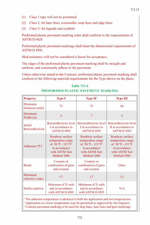
(1) Class 1 tape will not be permitted.
(2) Class 2: for lane lines, crosswalks, stop lines and edge lines
(3) Class 3: for legends and symbols
Preformed plastic pavement marking color shall conform to the requirements of ASTM D 6628.
Preformed plastic pavement markings shall meet the dimensional requirements of ASTM D 4505.
Skid resistance will not be considered a factor for acceptance.
The edges of the preformed plastic pavement marking shall be straight and uniform, and consistently adhere to the pavement.
Unless otherwise stated in the Contract, preformed plastic pavement marking shall conform to the following material requirements for the Type shown on the plans:
Table 713-2
PREFORMED PLASTIC PAVEMENT MARKING
Property Type I Type II3 Type III
Minimum thickness (mils)
75 75 60
MinimumWidth (in)
4 7 4
Initial Retroreflectivity
Retroreflectivity level I in accordance to
ASTM D 4505
Retroreflectivity level I in accordance to
ASTM D 4505
Retroreflectivity level II in accordance to
ASTM D 4505
Adhesion (ºF)1
Roadway surface temperature range of 50 ºF - 115 ºF2
in accordance with ASTM Test
Method 1000
Roadway surface temperature range of 50 ºF - 115 ºF2
in accordance with ASTM Test
Method 1000
Roadway surface temperature range of 50 ºF - 115 ºF
in accordance with ASTM Test
Method 1000
BeadsCeramic or
combination of glass and ceramic
Ceramic or combination of glass
and ceramicGlass
Minimum refractive index
1.7 1.7 1.5
Surface patternMinimum of 31 mils
and in accordance with ASTM D 4505
Minimum of 31 mils and in accordance
with ASTM D 4505N/A
1 The adhesion temperature is identical to both the application and test temperatures.2 Application at a lower temperature may be permitted as approved by the Engineer.3 Contrast pavement marking to be used for skip lines, lane lines and gore markings.
733
713.13

713.14 Preformed Thermoplastic Material.
(a) General. Preformed Thermoplastic markings shall be composed of aggregates, pigments, binders and glass beads, and shall conform to AASHTO designation M 249 with the exception of the relevant differences due to the fact that the material is supplied in a preformed state. The material shall be either alkyd or hydrocarbon based. Only preformed thermoplastic pavement marking material listed on the Department’s approved products list may be used.
(b) Physical Requirements.
1. Graded Glass Beads. The material shall contain a minimum of 30 percent graded glass beads by weight. The beads shall be clear and transparent. Twenty percent or less shall consist of irregular, fused spheroids, or silica. The refractive index shall be at least 1.50.
2. Pigments. White Sufficient titanium dioxide pigment shall be used to insure a color similar to Federal Highway White, Color Number 17886, conforming to Federal Standard 595. Yellow Sufficient yellow pigment shall be used to insure a color similar to Federal Highway Yellow, Color Number 13655, conforming to Federal Standard 595. The yellow pigment shall be organic and contain no lead chromate.
3. Skid Resistance. The surface of the preformed thermoplastic markings shall provide a minimum resistance value of 45 BPN when tested according to ASTM E 303.
4. Thickness. The material shall be supplied at a minimum thickness of 125 mils.
5. Environmental Resistance. The preformed thermoplastic material shall be resistant to deterioration due to exposure to sunlight, water, oil, gasoline, salt and adverse weather conditions.
713.15 Pavement Marking Tape.
(a) Description. The marking tape shall consist of weather and traffic resistant yellow or white colored reflective material. The material shall consist of conformable (metal foil) backing with a pressure sensitive adhesive designed for adhesion to asphalt or concrete surfaces.
(b) Requirements.
1. Color. The color of the visible or outer surface shall closely match the white or yellow traffic marking paint specified for highway delineation. Glass beads shall be strongly adhered to the tape.
2. Reflectance. The white and yellow tapes shall have the following initial minimum reflectance values at 0.20° and 0.50° observation angles and 86.00° entrance angle as measured in accordance with the testing
734
713.14
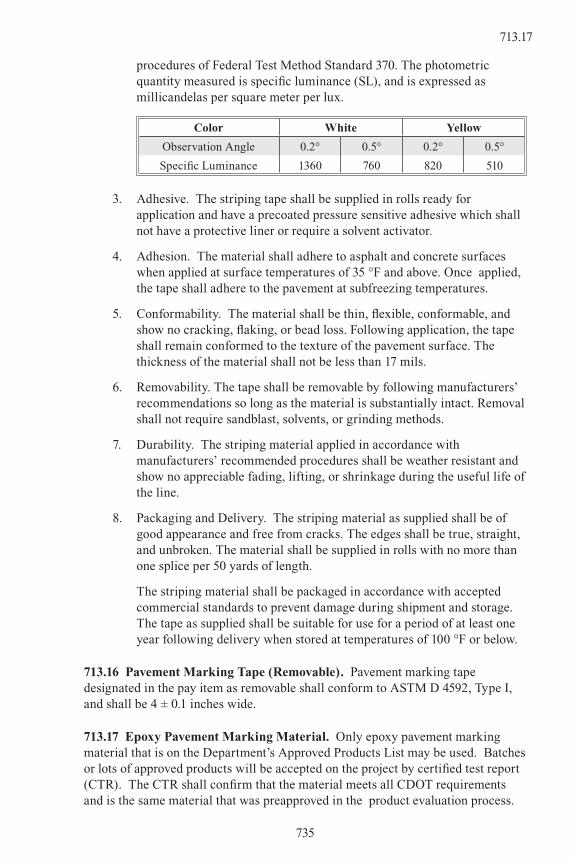
procedures of Federal Test Method Standard 370. The photometric quantity measured is specific luminance (SL), and is expressed as millicandelas per square meter per lux.
Color White Yellow
Observation Angle 0.2° 0.5° 0.2° 0.5°
Specific Luminance 1360 760 820 510
3. Adhesive. The striping tape shall be supplied in rolls ready for application and have a precoated pressure sensitive adhesive which shall not have a protective liner or require a solvent activator.
4. Adhesion. The material shall adhere to asphalt and concrete surfaces when applied at surface temperatures of 35 °F and above. Once applied, the tape shall adhere to the pavement at subfreezing temperatures.
5. Conformability. The material shall be thin, flexible, conformable, and show no cracking, flaking, or bead loss. Following application, the tape shall remain conformed to the texture of the pavement surface. The thickness of the material shall not be less than 17 mils.
6. Removability. The tape shall be removable by following manufacturers’ recommendations so long as the material is substantially intact. Removal shall not require sandblast, solvents, or grinding methods.
7. Durability. The striping material applied in accordance with manufacturers’ recommended procedures shall be weather resistant and show no appreciable fading, lifting, or shrinkage during the useful life of the line.
8. Packaging and Delivery. The striping material as supplied shall be of good appearance and free from cracks. The edges shall be true, straight, and unbroken. The material shall be supplied in rolls with no more than one splice per 50 yards of length.
The striping material shall be packaged in accordance with accepted commercial standards to prevent damage during shipment and storage. The tape as supplied shall be suitable for use for a period of at least one year following delivery when stored at temperatures of 100 °F or below.
713.16 Pavement Marking Tape (Removable). Pavement marking tape designated in the pay item as removable shall conform to ASTM D 4592, Type I, and shall be 4 ± 0.1 inches wide.
713.17 Epoxy Pavement Marking Material. Only epoxy pavement marking material that is on the Department’s Approved Products List may be used. Batches or lots of approved products will be accepted on the project by certified test report (CTR). The CTR shall confirm that the material meets all CDOT requirements and is the same material that was preapproved in the product evaluation process.
735
713.17

(a) Formulation. Epoxy pavement marking material shall be a two component, 100 percent solids, material formulated to provide simple volumetric mixing ratio of two volumes of component A and one volume of component B unless otherwise recommended by the material manufacturer.
(b) Composition. The component A of both white and yellow shall be within the following limits:
WHITE: YELLOW:
PigmentsMin % by weight 18%
Titanium Dioxide, (ASTM D 476, Type II)
% by weight21-27%
Epoxy Resin 75-82% 73-79%
The pigment for yellow epoxy shall contain no lead or other material such that the cured epoxy could be considered a hazardous waste under EPA or CDPHE regulations. The Contractor shall submit to the Engineer a manufacturer’s certification of compliance with this requirement.
(c) Epoxide Number. The epoxy number of the epoxy resin shall be 0.38 ± 0.05 as determined by ASTM D 1652 for white and yellow component A on pigment free basis.
(d) Amine Number. The amine number on the curing agent (component B) shall be 410 ± 50 per ASTM D 2071.
(e) Toxicity. Upon heating to application temperature, the material shall not produce fumes which are toxic or injurious to persons or property.
(f) Color and Weather Resistance. The mixed epoxy compound, both white and yellow, when applied to 3 inch x 6 inch aluminum panels at 15 ± ½ mils of thickness with no glass beads and exposed in the Q.U.V. Environmental Testing Chamber as described in ASTM G 154, shall conform to the following minimum requirements. (The test shall be conducted for 75 hours at 122 ºF, 4 hours humidity, and 4 hours U.V., in alternating cycles. The prepared panels shall be cured at 77 º F for 72 hours prior to exposure.) The color of the white epoxy system shall not be darker than Federal Standard No. 595B-17778. The color of the yellow epoxy system shall conform to Federal Standard No. 595B-13538. The gloss values of both samples shall not be less than 70° after the test.
(g) Drying Time. The epoxy pavement marking material shall have a setting time to a no-tracking condition of not more than 25 minutes at a temperature of 73 °F and above.
(h) Curing. The epoxy material shall be capable of fully curing under the constant surface temperature condition of 25 °F and above.
(i) Adhesion to Concrete. The catalyzed epoxy pavement marking material, when tested according to ACI Method 503, shall have such a high degree of adhesion to the specified (4000 psi minimum) concrete surface that there shall be a 100 percent concrete failure in the performance of this test.
736
713.17

(j) Hardness. The epoxy pavement marking materials, when tested according to ASTM D 2240, shall have a Shore D Hardness between 75 and 100. Samples shall be allowed to cure at room temperature, 75 ± 2 °F for a minimum of 12 hours and a maximum of 48 hours prior to performing the indicated test.
(k) Abrasion Resistance. The abrasion resistance shall be evaluated on Taber Abrader with a 1000 gram load and CS-17 wheels. The duration of the test shall be 1000 cycles. The wear index shall be calculated based on ASTM test method C-501 and the wear index for the catalyzed material shall not be more than 70. The tests shall be run on cured samples of material which have been applied at film thickness of 15 ± ½ mils to code S-16 stainless steel plates. The samples shall be allowed to cure at 75 ± 2 °F for a minimum of 48 hours prior to performing the indicated tests.
(l) Tensile Strength. When tested according to ASTM D 638, the epoxy pavement marking materials shall have a tensile strength of not less than 6000 psi. The Type IV Specimens shall be cast in a suitable mold and pulled at the rate of ¼ inch per minute by a suitable dynamic testing machine. The samples shall be allowed to cure at room temperature (75 ± 2 °F) for a minimum of 12 hours and a maximum of 48 hours prior to performing the indicated tests.
(m) Compressive Strength. When tested according to ASTM D 695, the catalyzed epoxy pavement marking materials shall have a compressive strength of not less than 12,000 psi. The cast sample shall be conditioned at room temperature, 75 ± 2 °F, for a minimum of 12 hours and a maximum of 48 hours prior to performing the tests. The rate of compression of these samples shall be no more than ¼ inch per minute.
713.18 Raised Pavement Marker. Raised pavement marker shall not be less than 3.5 inches or more than 4.5 inches in the major dimension and not more than 0.75 inch in height. The marker shall contain a retroreflective element not less than 0.38 square inch in area. The color of the marker and the retroreflective element shall match the color of the pavement marking line. The reflective quality requirements shall be at least equal to the following minimum values:
ObservationAngle
Degrees
EntranceAngle
Degrees
Specific IntensityCandela per Lux
White Yellow
0.1 0 0.09 0.06
0.1 20 0.04 0.02
The marker shall be ceramic or plastic and shall be secured to old or new pavement using an adhesive approved by the marker manufacturer.
713.19 Methyl Methacrylate Pavement Marking. The Methyl Methacrylate material shall be preapproved by the Department.
737
713.19

SECTION 714PRESTRESSED UNIT MATERIALS
714.01 Prestressing Steel. Prestressing reinforcement shall be manufactured from high tensile strength steel or alloyed steel. Reinforcement size and grade shall be designated in the Contract. Prestressing steel materials shall meet the appropriate following requirements:
(1) Seven wire steel strand shall meet the requirements of AASHTO M 203. All furnished strand shall be “weldless” in accordance with AASHTO M 203, subsection 8.1.4. The Contractor shall furnish one test specimen per coil. Each test specimen shall be 5 to 6 feet long.
(2) High tensile alloy bars shall meet the requirements of AASHTO M 275. Unless otherwise approved by the Engineer, the Contractor shall furnish two test bars per diameter size, per heat number. Each test bar shall be 5 feet in length.
All testing specimens shall be furnished free of cost. If test specimens are not delivered in time for tests to be performed prior to time of use, the Contractor may elect to incorporate materials into the work at the Contractor’s own risk. All test specimens shall be representative of the furnished material lot. If ordered by the Engineer, selection of test samples shall be witnessed by the Engineer’s representative, at any location chosen by the Engineer.
All prestressing unit materials shall be subject to interim inspection and testing, before, during and after incorporation into the work, as ordered by the Engineer.
714.02 Anchorage Assemblies. If the anchorage assemblies are not attached to the reinforcement samples, the Contractor shall furnish two anchorage assemblies, complete with distribution plates, for each size or type to be used when requested by the Engineer.
714.03 Post-tensioning Products. The following lengths of materials shall be furnished by the Contractor:
(1) For strand to be furnished with fittings; 5 feet between near ends of fittings.
(2) For bars to be furnished with threaded ends and nuts; 5 feet threads at ends.
738
714.01

SECTION 715LIGHTING AND ELECTRICAL MATERIALS
715.01 General. Materials shall be of a standard line from a name brand manufacturer. Electrical material shall be listed by the Underwriters’ Laboratories, Inc., and shall conform to the National Electrical Code.
Material shall be the same as, or compatible with, that used and accepted by the agency responsible for maintenance.
The Engineer may inspect all lighting materials and all electrical materials and accept or reject them at the project site. Samples may be taken or manufacturer’s certifications may be accepted in lieu of samples.
715.02 Light Standard Foundations and Concrete Foundation Pads. Concrete shall be Class B conforming to Section 601.
Anchor bolts shall be designed by the Contractor’s Engineer and shown on the working drawings. The threaded ends of the anchor bolts, the nuts, and the washers shall be galvanized in accordance with ASTM A 153. Galvanizing on anchor bolts shall extend 2 to 4 inches beyond the threads.
Reinforcing steel shall conform to Section 602.
715.03 Light Standards.
(a) General. All structural components of light standards, bases, couplers, anchor bolts, luminaires, and other attachments to be used for lighting shall be designed for a minimum of 100 MPH wind velocity, in accordance with AASHTO’s Standard Specifications for Structural Supports for Highway Signs, Luminaires, and Traffic Signals,.
All breakaway bases and couplers shall meet the breakaway requirements specified in AASHTO’s Standard Specification for Structural Supports for Highway Signs, Luminaires, and Traffic Signals, Section 12. Conformance shall be verified by crash tests reviewed and accepted by FHWA. A certificate of compliance shall be provided.
(b) Metal Light Standards. Metal light standards shall be fabricated of either steel or aluminum, unless otherwise specified. Whenever Light Standard Metal is specified, the Contractor may furnish either steel or aluminum. Material type and shape of light standards shall be the same throughout the project, unless otherwise shown in the Contract.
All standards shall have cable-entrance holes located in conformity with the type of arm mounting used. Metal surfaces shall be free of imperfections marring the appearance and of burrs or sharp edges that might damage the cable.
739
715.03

All metal poles shall be tapered and shall be supplied with pole caps.
Aluminum alloys shall have a minimum yield strength of 25,000 psi. Aluminum poles, arms, and fittings shall be made of aluminum alloy conforming to the following for the material form required:
ASTM Standard Alloy Number
B 209 6061-T6
B 211 6061-T6
B 221 6061-T6
6063-T6
6005-T5
B 241 6061-T6
6063-T6
Aluminum poles may also be made of aluminum alloy 5086-H34 conforming to ASTM B 313 (excluding pressure and burst tests).
Aluminum mast arms shall be tapered unless otherwise shown on the plans.
Steel mast arms shall be made of Schedule 40 standard steel pipe conforming to ASTM A 53.
All steel poles, mast arms and base flanges shall be hot-dip galvanized in accordance with ASTM A 123. Units on which the spelter coating has been damaged shall be repaired as provided in AASHTO M 36, or other approved method.
Base flanges for both aluminum and steel poles shall have continuous welds both inside and outside, unless otherwise permitted. Base flanges inserted into the pole and bonded shall meet the requirements for materials and strength stated herein.
Base flanges for aluminum poles and transformer bases shall be aluminum castings of alloy ANSI 356.0-T6 or UNS A03560 T6 conforming to ASTM B 26 or an acceptable equivalent.
Each metal light standard shall be wired with a breakaway fused connector of proper capacity rating. The fused connector shall be located in the transformer base. If the light standard has no transformer base, the fused connector shall be located in the pole at the hand hole.
All transformer bases shall have vandal resistant, removable access doors.
The transformer base shall be a frangible breakaway type as shown on the plans and shall accommodate the anchorage and base flange of the light pole supplied. Each transformer base shall have a ½ inch bolt or lug fastened inside the base for grounding; the lug or bolt shall be visible from the door opening. The transformer base shall have a wire hole for outside grounding, if required.
740
715.03

(c) Hardware used with steel standards shall be either cadmium plated steel, hot dip galvanized steel, or stainless steel. All hardware used with aluminum standards shall be anodized aluminum or stainless steel. Bolts to be inserted in aluminum threads shall be stainless steel.
715.04 Luminaires and Lamps. Luminaires shall be UL or ETL Listed for use in wet locations and IP66 rated. Luminaires shall be adaptable to the type of power distribution system to be used.
(a) General. Luminaires shall conform to the following requirements:
1. Housing. The luminaire enclosure shall be an injection-molded or die-cast opaque housing. The housing shall have a powder-coated, corrosion-resistant finish. The color shall be as specified on the plans. The mounting shall be as shown on the plans.
The housing shall have a door that provides access to all internal components. The door shall be equipped with a safety catch and a latch. The housing shall have an inner rolled flange to support the door frame. The door frame shall be an aluminum casting, hinged to the housing. The door frame shall be sealed to the housing with a molded silicone gasket and shall be secured with a minimum of four captive screws.
2. Optical Chamber. The luminaire distribution shall be an IESNA full-cutoff, type III reflector system for lamps over 3200 lumens. The optical chamber shall be completely sealed from the housing, or the housing shall be completely sealed. A seamless one piece memory-retentive gasket shall seal the optical chamber or housing against the luminaire lens door. All wires entering the optical chamber shall be gasketed at their point of entry. Socket mountings, rivets used in the construction or support of the reflector system, and all other penetrations into the optical chamber shall be completely sealed. The optical chamber shall be water tight when the luminaire door is closed.
3. Lens and Lens Door. The lens shall be constructed of clear, flat (for lamps over 3200 lumens), tempered glass. The glass shall be thermal-resistant and impact-resistant. The lens shall be sealed to the door frame with continuous silicone gasketing. The door shall have an easy-access, quick-release safety latch. The door shall have aluminum or stainless steel quick-release hinge pins for tool-less or one-hand easy and secure opening. When the door is closed, the electrical component compartment and the optical chamber shall be completely sealed.
4. Electrical Components. All components shall be UL listed for wet locations. Luminaires shall operate at either 120 or 240 VAC as specified on the plans or adaptable to the type of power distribution system to be used. Sockets shall be porcelain with nickel plated current-carrying parts. Sockets shall be rated for at least 600 VAC at 302 °F. All internal wiring and quick disconnects shall be rated for at least 600 VAC and insulated for 203 °F The ballast or induction lamp power generator shall
741
715.04
be easily removable from the luminaire housing without the use of tools. If induction lamps are used, the luminaire shall be designed for the operating conditions of an induction lamp.
(b) Roadway Luminaires. Roadway luminaires shall be high pressure sodium, induction, or metal halide. All luminaires for the project shall be the same type and design unless the plans specify otherwise. Cobra head style shall have a bubble level for leveling.
(c) Wall and Pendant Type Luminaires. Wall and pendant type luminaires for use under overpass structures shall be complete, pre-wired lighting devices. Luminaire shall be furnished with a fixed hood for moderate glare control along roadway.
(d) Pedestrian Luminaires. Pedestrian luminaires shall be the type and style shown on the plans.
(e) Lamps. Lamps for luminaires shall be high pressure sodium, metal halide, compact fluorescent, or induction-type of the wattage shown on the plans. Mercury vapor shall not be used.
Lamps shall be installed and operated only in luminaires designed to accommodate the specific lamp. Lamps shall be compatible with ballasts and power generators supplied with the luminaires in which they are to be installed. Metal halide (150 watts or less), fluorescent, and induction lamps shall have a color temperature of 3000K. All lamps of a similar type shall be provided by the same manufacturer.
The induction lamp system shall consist of three main components: the vessel, the power coupler, and the high frequency power generator. All three components shall be supplied by one manufacturer as one system and shall be warranted by the manufacturer for parts and labor for a minimum of five years. The power factor shall be greater than 0.9, and the total harmonic distortion shall be less than 10 percent.
715.05 Ballasts and Induction Lamp Power Generators.
(a) Ballasts. Ballasts shall be the magnetic regulator type specifically manufactured for use with the lamp shown on the plans, and shall operate at a minimum of 90 percent power factor. Operation shall be suitable with a line voltage variation of ±10 percent. Satisfactory starting operation shall be obtained with an ambient temperature of -20 ˚F. Electronic ballasts for metal halide lamps of 150 watts or less shall have an ANSI Transient Insulation Level of at least 10,000 VAC for roadway lighting applications.
(b) Induction Lamp Power Generators. Power Generators shall be supplied with the lamp. Power generators for induction lamps shall have an input voltage of 120 or 240 VAC/60Hz. Minimum operating temperature shall be -40 °F. The heat sink shall be designed to maintain 80 percent of peak luminous flux in ambient temperatures between -10 °F and +110 °F.
742
715.04

715.06 Conduit. Unless otherwise specified, conduit shall be rigid metallic or semirigid plastic electrical conduit. Metallic conduit shall be clean, free of burrs, and galvanized.
Plastic conduit shall be a semirigid type currently recommended and approved by Underwriters’ Laboratories, Inc. for the proposed use. Underground plastic conduit for street lighting shall conform to ASTM-F 441 schedule 80. Fittings shall be the type used outside the conduit. Fittings shall connect the conduit in a manner that makes the joints watertight.
Junction boxes used in structures shall be galvanized steel, 6 inches square by 4 inches deep, with weatherproof covers.
Pull boxes and splice boxes shall be a minimum of 16 inches by 12 inches and 6 inches deep unless otherwise shown on the plans. Pull and splice boxes shall have heavy duty weatherproof covers rated for roadway applications. The housing shall be resistant to sunlight exposure, weathering, and chemicals; it shall be unaffected by freeze/thaw cycles. Covers shall fit flush to the sidewalk, turf area, or roadway surface. Hardware and inserts shall be stainless steel. The cover for street lighting circuits shall be marked “ELECTRICAL” or “STREET LIGHTING”. The cover shall list the minimum HS load rating of 20,000 psi.
715.07 Lighting Circuitry and Wiring. Lighting systems shall be photoelectric controlled. Photoelectric controls shall be the hermetically sealed, cadmium sulfide twist-lock type with high impact polypropylene cover with clear UV stabilized window. Photoelectric controls shall have a turn-on setting of 1.4 foot-candles ± 0.2 foot-candles. The maximum ratio of the turn-off to turn-on setting shall be 3:1.
All electrical apparatus used in the lighting system shall be rated to adequately handle the necessary loads and shall conform to power source requirements.
715.08 Secondary Service Pedestals and Lighting Control Centers. Secondary Service Pedestals and Lighting Control Centers shall be metal conforming to ANSI C47.12.28, Pad Mounted Enclosure Integrity Standard and shall be the nominal size and dimensions shown in the Contract.
The cabinets shall be constructed of 12 gauge corrosion-resistant steel with hoods and covers constructed of 14 gauge corrosion-resistant steel. Cabinets shall be NEMA 4 construction and shall be UL listed as “Enclosed Industrial Control Equipment” (UL508). Cabinets shall be vandal resistant dead-front enclosures.
The cabinet’s external finish shall be polyurethane industrial grade powder paint of 1.7 mil minimum thickness. The cabinet’s internal finish shall be polyurethane industrial grade powder paint of 1.7 mil minimum thickness or bare aluminum.
All external fasteners, rivets, screws and bolts shall be stainless steel. Fasteners, except sealing screws, shall not be removable by external access. Hinges shall be stainless steel continuous piano hinge type hinges.
743
715.08

External nameplates shall be permanently attached to the cabinet. A stainless steel handle shall be provided on the front exterior of each cabinet door or hood. Cabinet shall be equipped with a three point catch and lock. These locks shall be furnished with two keys for each cabinet, and all locks shall be master keyed Type I police lock. When final acceptance of the project is made, the Engineer will distribute the keys to the agencies responsible for maintenance of the system.
The cabinet shall have separate isolated sections for metering equipment (if required), utility termination, and CDOT equipment. All sections must be sealed and pad lockable.
The metering section shall have a hinged swing back hood with an integral hinged polycarbonate sealable window for visual access to meters.
The utility termination section shall be sealed and securable with a padlock. The section shall have a lift off cover with a stainless steel handle. Sufficient clearance shall be provided for a 4 inch diameter conduit for utility cables. Utility landing lugs shall be UL listed and shall accommodate 6 - #350 kcmil conductors.
The CDOT compartment door shall be sealed and securable with a padlock. The compartment door shall be anchorable in an open position. There shall be a print pocket on the inside of the door. The print pocket shall hold all wiring schematics and instructions in a clear weatherproof sleeve with a side opening. Required UL labeling shall be located on the inside of the CDOT door. Distribution and control equipment shall be behind an internal dead-front door with a quarter-turn securing latch and be hinged to open more than 90 degrees. The dead-front door shall be hinged on the same side as the CDOT section door.
Pedestal mounting bolts shall not be visible or accessible externally. Pedestal mounting shall include pedestal mounting base and hardware. Pad mounting shall include concrete pad mounting base, anchor bolt kit and hardware.
Secondary Service Pedestals and Lighting Control Centers shall be rated for 600 VAC, installed with protection against damage from greater currents. The pedestals and centers shall be grounded with grounding rods in conformance with the National Electric Code. The following equipment is for a typical installation and may or may not be required as shown on the plans:
(1) Meter Sockets (100 amp minimum)
(2) Main circuit breaker that is installed in a circuit load center as sized on the plans
(3) Circuit load center with an all-copper bus for CDOT loads as shown on the plans
(4) Circuit breakers
(5) Ground Fault Interrupter Receptacle (20 amp, 120 VAC)
(6) Multiple Pole Light Contactors
(7) Test Switch
(8) Photoelectronic Control Relay
744
715.08
(9) Mounting pans or false backs for circuit breakers, contactors, relays, switches, transformers, and other types of electrical equipment mounted inside the cabinet
The internal wiring of cabinets shall be assembled by a UL listed facility. Cabinets shall conform to one or more of the following standards where appropriate: UL 50, Cabinets and Boxes; UL 67, Panel Boards and UL 869A, Service Equipment.
Circuit breakers and equipment shall be labeled with an engraved permanent label on the dead-front panel to indicate the circuit controlled.
Multiple Pole Light Contactors shall be “lighting” type, specifically rated for the type of lighting load specified. The contactors shall have a 600 Volt rating. All multiple pole light contactors shall be unenclosed, single phase with the number of poles specified on plans; they shall be open type lighting contactors with the rating shown or specified. Contactors shall be constructed for surface mounting on a false back or bracket within a weatherproof cabinet. The contactor coil shall operate on 120 Volt for 240 Volt circuits and 240 Volt, 208 Volt, and 277 Volt for 480 Volt circuits. Contact material shall be designed for lighting ballast loads and require no maintenance such as filing, burnishing, or dressing at any time the contactor is in service.
A 277 VAC rated test switch shall be installed in the control cabinets if shown. The test switch shall be a heavy-duty single pole switch or circuit breaker rated at 20 amps and shall be installed in the control cabinet as a roadway lighting test switch. The switch shall be wired to shunt the photoelectric control relay power contactor and energize the lighting circuit contactors.
All components of the photoelectric control relays shall be housed in a weatherproof, locking, non-rusting container. The photoelectric control relay shall attach to a three pole locking receptacle by a twisting motion.
The photoelectronic control shall have a built in surge protective device for protection from induced high voltage and overcurrents. The photoelectric control relay shall meet or exceed the requirements of ANSI C136.10. The photoelectric control shall be factory set to turn on lights when ambient light falls to 1.4 footcandle plus or minus 0.2 footcandle when operated at 120 VAC. When operated at 250 VAC, turn on shall not change more than plus or minus 0.3 footcandle from the 120 VAC value. The maximum off to on ratio shall be 1.5:1. The photoelectric control shall be a cadmium sulfide photoelectric control encapsulated for humidity protection, or a silicon junction type photo transistor. The photoelectric control shall be designed for normal operation at a dual voltage of 105 V and 285 V. Power consumption shall be less than 1 watt. At the designated voltage, the photoelectric control shall be capable of controlling a minimum load of 1000 watts. Minimum operating temperature range shall be from -40 °F to 150 °F. A time delay control circuit shall prevent false turn offs by transient lighting conditions. The unit shall include a failsafe circuit for the lighting load such that the lighting systems remain energized if any functional failure of the photoelectric control circuit occurs.
745
715.08

SECTION 716WATER LINE MATERIALS
716.01 Cast Iron Pipe. Cast iron pipe shall conform to the requirements of Federal Specification WW-P-421, Class 150 with Type III mechanical joints.
716.02 Welded Steel Pipe. Welded steel pipe shall be of the length, diameter and metal thickness shown on the plans and shall conform to the following:
(1) Pipe shall conform to the applicable requirements of AWWA Standard C 200, Section 3, manufactured from steel sheets conforming to ASTM A 1011, Grade 33 or 36, plates conforming to ASTM A 283 Grade C or D, or ASTM A 572 Grade 42; or it shall be manufactured to meet the requirements of ASTM A 53, Grade B or ASTM A 139 Grade B or C.
(2) Surface Preparation and Coating. Inside and outside surfaces shall be blast cleaned with sand, steel grit, steel Shot or a combination of steel grit and steel shot to remove mill scale and rust, in accordance with subsection 509.24(b). Pipe that is cement mortar lined in accordance with AWWA Standard C205 shall not be blast cleaned. Paint and coating schedule for pipe larger than 10 inch shall conform to Table 716-1.
TABLE 716-1
FOR PIPES CARRYING POTABLE WATER
Pipes to be disinfected after installation, in accordance with AWWA Standards
Buried Pipe Exposed Pipe
Interior Exterior Interior Exterior
Lined with cement mortar in accordance with AWWA Standard C 205
80 mil thickness tape coating systems for the exterior of steel water pipelines in accordance with AWWA Standard C 214
Lined with cement mortar in accordance with AWWA Standard C 205 or coal tar epoxy in accordance with Corps of Engineers C 200
Subsections509.24 and 509.29
FOR PIPES CARRYING NON-POTABLE WATER
AND FOR SEWERS
Buried Pipe Exposed Pipe
Interior Exterior Interior Exterior
Lined with cement mortar in accordance with AWWA Standard C 205 or coal tar epoxy in accordance with Corps of Engineers C 200
80 mil thickness tape coating systems for the exterior of steel water pipelines in accordance with AWWA Standard C 214
Lined with cement mortar in accordance with AWWA Standard C 205 or coal tar epoxy in accordance with Corps of Engineers C 200
Subsections509.24 and 509.29
746
716.01

Type of pipe and its coating for pipe 10 inch and smaller shall be as shown on the plans.
Bell and spigot ends with rubber gaskets, flanges, mechanical couplings, or field welded joints may be used, as conditions require to join the pipe.
All field welds shall conform to Section 509 and shall have linings and coatings replaced equal to the original coating. Wire brushing shall be used where necessary to clean the pipe.
Where cement mortar lining is used with welded joints or bell and spigot ends with rubber gaskets, the joint cut back shall be mortared after the pipe has been laid. This cement mortar lining and application shall conform to AWWA Standard C 205.
On buried pipe coated with a tape coating system conforming to AWWA Standard C 214, the field joints shall be cleaned, primed, and wrapped with two thicknesses of 35 mil cold applied elastomeric joint tape conforming to AWWA Standard C 209, Type 11.
Damage to the pipe lining or coating due to the Contractor’s operation shall be repaired at the Contractor’s expense.
716.03 Galvanized Pipe. Galvanized pipe and fittings shall conform to the requirements of ASTM A 53.
716.04 Copper Pipe. Copper pipe shall conform to the requirements of ASTM B 88, Type “K” and shall be annealed. Pipe shall be supplied with solder type fittings.
716.05 Plastic Pipe. Polyethylene pipe (PE) shall conform to the requirements of ASTM D 2104 when size, type, and schedule or series are designated or ASTM D 2239 when size and pressure ratings are designated. Polyvinyl Chloride pipe (PVC) shall conform to the requirements of ASTM D 1785 when size and schedule are designated or ASTM D 2241 when size and pressure ratings are designated.
All plastic pipe used as water pipe must bear the National Sanitation Foundation (nSf) seal of approval.
716.06 (unused)
716.07 Valves and Valve Boxes. Valves shall be designed to exceed the required working pressure of the water line but shall not be less than the values herein.
(a) Gate Valves.
1. General. Valves shall have non-rising stems, unless otherwise specified, with inside screw and shall open to the left or counterclockwise. Valves shall be equipped with double O-ring stem seals conforming to AWWA C500. All valves shall have the manufacturer’s names, catalog number and working pressure molded or stamped thereon. Valves shall be painted as specified in AWWA C500, Section 27, and shall be furnished complete with all accessories. Ends of valve shall fit the pipe or fitting to which attached (push-on, mechanical, bell-and-spigot or flanged).
747
716.07

Gate valves shall be for buried service, however, they shall be protected against freezing above the frost line.
2. Valves Smaller than 3 Inch. Valves shall be of the wedge-disc type with non-rising stem, screw ends and bronze body. Metal composition of the body, center-piece and other cast parts shall be cast bronze meeting the requirements of ASTM B 62. All packing shall have each ring cut to fit, with staggered joints. Continuous (spiralled) packing shall not be used. Valves shall be provided with handwheels and stuffing box glands. Unless otherwise specified, valves shall be for 200 pound water service.
3. Valves 3 Inch and Larger. Valves 3 inch and larger shall conform with AWWA C500, except that they may be furnished with 2 inch square operating nuts or hand-wheels.
Bypasses, when required, shall conform to the details shown on the plans or established.
The intended position of the valve in the water line (either horizontal or vertical) shall be as shown on the plans.
(b) Other Valves. Butterfly valves, globe valves, air relief valves, check valves, tapping valve and sleeve and other appurtenances shall be as shown on the plans.
(c) Valve Boxes. Unless otherwise specified or shown on the plans, valve boxes shall be of the adjustable screw type, complete with drop cover.
748
716.07

SECTION 717REST AREA AND BUILDING MATERIALS
717.01 General. All materials and equipment shall be new and shall be of recognized standard quality.
717.02 Masonry and Masonry Wall Reinforcement.
(a) Masonry. Concrete blocks or concrete ornamental blocks shall be light-weight aggregate concrete blocks conforming to ASTM C 129, Type 1. Corner block shall be installed at all wall openings. All block shall be uniform in color and be smooth textured. Ornamental block shall be of the type as scheduled on the plans.
Structural glazed tile shall be of the types, color, and sizes shown on the plans.
Face brick shall be 2¼ inch x 35/8 inch x 75/8 inch (nominal 8 inch) modular size brick. Brick required at ends of rowlock shall be solid brick (no holes). All face brick shall conform to ASTM C 216, Grade SW Type FBS (rough). The style of brick to be used shall be as scheduled on the plans.
(b) Masonry Wall Reinforcement. Masonry wall reinforcement for curtain walls, shelter wall panels and information center wall panels shall be ladder type for 6 inch wall, 9 gauge, galvanized, with deformed side rods.
“Z” ties for cavity walls of building shall be 3/16 inch x 6 inch galvanized rod.
Corrugated wall ties shall be 7/8 inch x 7 inch x 20 gauge galvanized steel.
717.03 Mortar for Masonry and Structural Glazed Tile. Mortar shall conform to subsection 704.04. Coloring shall be added to the mortar for the face brick to yield a mortar compatible with or approximating the color of the face brick.
Remixing or retempering of mortar will not be permitted.
Waterproofing compound shall be used in all mortar. Mixing waterproofing compound with mortar shall be in strict accordance with the manufacturer’s instructions.
717.04 Metal Specialties.
(a) Metal Toilet Stalls. Metal compartments for toilet rooms shall be of the type and style as scheduled on the plans.
Each toilet compartment shall be furnished with a cast alloy chrome plated Combination Coat Hook and Bumper and a chrome plated, single-fold type toilet paper dispenser.
(b) Mirrors. Mirrors shall have clear anodized aluminum or stainless steel vandal-proof frames with finish similar to #44 satin stainless steel. Corners shall be mitered and reinforced. Mirror glass shall be ¼ inch thick, #1 quality polished plate, 18 inch wide x 24 inch high, of the type and style as scheduled on the plans.
749
717.04

717.05 Sanitary Napkin Disposal. Sanitary napkin disposal shall be of the type and style as scheduled on the plans.
717.06 Doors, Frames and Windows. General. All steel doors, door frames and windows shall be as scheduled on the plans.
All doors shall be full flush type, with no exposed seams.
(a) Frame and Window Construction. All frames shall be No. 16 gauge steel, with 2 inch face, ½ inch or 5/8 inch integral stops and 5 ½ inch or 5 ¾ inch depth.
Window frames and door frames shall be shipped as “set up,” when welded units are used, with all comers and intersections welded and ground smooth. Frames may be knocked-down when units with steel tabs are furnished. Window frames shall have bottom panels of heights shown on the plans.
Hinge jambs shall be mortised for 4 ½ inches x 4 ½ inches template hinges and prepared for the ANSI Universal lock strike, or approved equal.
(b) Door Hardware. Hardware shall be reinforced and completely prepared for field attachment into drilled and tapped holes.
All hardware, whether specifically mentioned or not, required to fully complete the work as shown on the plans and in the specifications, shall be included and of the same type and quality as that specified herein.
All hardware shall be as scheduled on the plans. Lockset shall conform to Federal Specification FF-H-00106b, Series 86C-4 where applicable and shall be mortise type. Finish of all hardware shall be U.S. 10 as identified in Fed. Spec. FF-H-00106b, Sec. 6.8, Table II.
(c) Hardware Sets. For hardware locations refer to the door schedule on the plans.
(d) Keying. All doors shall be keyed alike. Three keys shall be furnished per building.
717.07 Ceramic Tile. Unless otherwise specified, all tile shall conform to ASTM C 126.
All floor tile shall be delivered to the job in unopened, sealed containers. They shall be accompanied with a certificate of grade signed by the manufacturer and the Contractor, together with adequate identification of the containers.
Ceramic floor tile shall be of unglazed tile of the style and pattern as scheduled on the plans. Ceramic tile for the Mosaic shall be 1inch x 1 inch squares and part squares. The colors and placement shall be as shown on the plans.
The Contractor shall submit samples to the Engineer for approval, in duplicate, of each kind of tile proposed for use. When approved, one sample shall be retained for comparison with the finished work.
750
717.05

717.08 Roofing, Flashing and Roof Insulation. General. All roofing materials shall bear the manufacturer’s label on sealed packages. All insulation shall be marked for proper identification.
Asphalt for applying roofing shall conform to ASTM D 312, Types I, and III.
Felt for roofing shall be Type II (30 pound type) (not perforated) for the base sheet, and Type I (15 pound type) (perforated) for additional layers. Felt shall conform to ASTM D 226.
Roofing aggregate shall meet the quality requirements of subsection 703.02 and shall be graded uniformly with 100 percent passing the 19.0 mm (¾ inch) screen and 100 percent retained on the 4.75 mm (No. 4) screen.
Lumber shall be construction grade or better, Douglas Fir, Larch or Hemlock.
Shingles shall be good grade (No. 2) cedar shingles, with a weight of not less than 36 pounds per bundle.
All membrane roofing shall be 4 ply. Lumber roofing shall be as shown on the plans.
All joints shall be sealed with a two component type, polysulfide-base synthetic rubber sealant or an approved equal. Sealant shall meet the requirements of ANSI A 116.1, Class B. Primer shall conform to the requirements of the manufacturer of the sealant used.
Joint filler used as back up for sealant shall be plastic foam joint filler.
Care shall be taken to ensure that back-up material shall not contain any asphalt. (Asphalt is incompatible with this type sealant).
717.09 Carpentry. Ceiling panels, adhesive for panels, moldings to conceal joints, corners and intersections of panels and walls, color and style of panels shall be as scheduled on the plans.
717.10 Interior Insulation. All insulation, except that required for roof or in frame walls, shall be expanded polystyrene having a “K” factor of 0.26 (average) at a mean temperature of 70 ˚F and a Perm rating of 1.2 or less, with thicknesses as shown on the plans. Adhesive for bonding the insulation to the masonry walls shall be an asphalt emulsion material that is acceptable to the manufacturer of the insulation. Insulation required for underside of roof or in frame walls shall be blanket-type fiber glass, thickness as shown on the plans with a density of ¾ pound per cubic foot and shall have a vapor barrier of the embossed vinyl, scrim reinforced, aluminum foil type.
717.11 Glass and Glazing. All glass shall be obscure type, ¼" thick, rough one side and polished one side or as called for on the plans.
All glass shall bear the identifying label of the manufacturer.
751
717.11

717.12 Trash Receptacles. The trash receptacles shall be of the type and style as scheduled on the plans. Each receptacle shall be furnished with 25 disposable polyethylene liners.
Receptacles shall be painted with baked enamel finish, Metallic Gray bottom and Sea Mist top.
717.13 Paint and Special Coating. The special makes of prepared paints, sealant or special coatings that may be specified or otherwise required must be delivered in the original package with the seals unbroken and labels attached.
717.14 Plumbing. The sanitary drainage system within the building and to the septic tank or sanitary hookup shall be made of standard weight cast iron soil pipe. The pipe shall be furnished in standard lengths with inner and outer surfaces concentric, smooth inside and free from defects. Any pipe cracked in cutting shall be removed.
Cast iron pipe, including bell, shall weigh not less than the following average weights per 5 foot of length:
2 inches 20 pounds
3 inches 30 pounds
4 inches 40 pounds
6 inches 65 pounds
Fittings for cast iron pipe shall be standard design fittings of the same inside diameter as the pipe with which they are used, and of equal quality and weight in all parts.
Cast iron pipe and fittings shall conform to Commercial Standard CS 188 for Standard Weight Cast Iron Soil Pipe and Fittings.
Lead for caulking joints in cast iron pipe shall be soft pig. All oakum shall be pitched. Use 12 ounces of lead for each 4 inch diameter of pipe used.
All hot and cold water piping and supply lines above grade shall be Type L, copper pipe with sweated and brazed fittings. Pipe, valves and fittings shall be of Bridgeport, Case or Mueller, or an approved equal. Connections involving different metals shall require a dielectric union. Solder shall be 95.5 tin and antimony, and shall be applied as per manufacturer’s instructions.
Underground water lines under concrete slab of the building shall be ASTM B 88, Type “K” hard drawn copper pipe with brazed fittings. Brazing material shall be silver solder.
Pipe for sewage vent lines shall conform to the Colorado Plumbing Code. A suitable vent screen shall be provided for each vent line.
Underground water line to building, sanitary station and trailer pad shall be 100 psi pressure rated, virgin polyethylene pipe.
752
717.12
Fittings shall be of polyethylene or nylon with stainless steel clamps. All pipe and fittings shall be approved by the National Sanitation Foundation and shall bear that mark.
717.15 Heating and Ventilating.
(a) Heaters. The wall heaters shall be of the make and model scheduled on the plans.
The forced air furnace shall be of the make and model scheduled on the plans with adjustable pulley type belt drive blower. Motor shall be 120 V/60 cycle single phase. Furnace shall be complete with cabinet, electric heating section, blower, filters, motor, belt drive, adjustable pulley on motor, safety controls, relays, and all other items as may be incidentally required for a complete and ready to operate installation. Capacity shall be as indicated on the plans.
(b) Grills. Grill location, model, style and sizes shall be as shown on the plans.
(c) Thermostat. Thermostats shall be as specified under electrical work in subsection 717.16.
(d) Exhaust Fan and Curb. Exhaust fan shall be of the make and model scheduled on the plans. Fan shall be mounted on a prefabricated curb equipped with automatic back draft damper. Fan shall be operated by a timer. Fasten curb directly on top of sheathing.
(e) Duct Work. Duct work shall be fabricated from galvanized steel sheets in accordance with recommended practice as outlined in the current edition of the American Society of Heating, Refrigeration and Air Conditioning Engineering Guide. Aluminum may be used at the Contractor’s option and shall conform to gauge shown in the table below. All duct work shall be fabricated from the one material selected by the Contractor.
The following sheet gauges and thicknesses shall be used throughout:
MaximumSide
(Inch)
Steel U.S.Gauge
AluminumThickness
(Inch)
Type OfTransverse
Joint*Bracing
Up to 12 26 .020S, Drive Pocket or Bar Slips, on 7"-10" centers
None
13 to 18 24 .025 None
19 to 30 24 .0251" x 1" x 1/8"
at 60"
* Other joint connections of equivalent mechanical strength and air tightness may be used.
The flat side of all ducts shall be cross broken.
753
717.15
All horizontal ducts are to be supported with angle iron hangers secured to the construction above, at intervals not to exceed 7'-10". All vertical riser ducts shall be supported at floor and ceiling with angle iron rests secured to the ducts.
(f) Outlets, Inlets and Vents. All outlets, inlets and vents shall be of the type and style called for on the plans, or an approved equal.
717.16 Electrical.
(a) Conduit. Conduit below grade, finish floor elevation, or embedded in concrete shall be rigid steel, hot dipped, sherardized or galvanized, unless otherwise specified. Each length of conduit shall be stamped with the name or trade mark of the manufacturer and shall bear the Underwriter’s Laboratories, Inc. label.
Thin wall electrical metallic tubing conduit will be permitted above grade, unless otherwise noted on the plans.
(b) Conduit Fittings. Conduit fittings shall be compatible with the conduit furnished, with cast covers and where installed exposed to the elements, shall have vellum or fiber gaskets.
(c) Conductors. All 120 and 220 volt wire and cable shall be single conductor, soft drawn, copper wire with 600 volt insulation. Type TW shall be used for overhead runs. Type THW shall be used in runs under floor slab inside building.
Cable serving water wells, may be one cable of 3 conductor, Type USE; three single conductors, Type USE, placed in the same trench; or 2 conductor Type UF, with ground wire. The wire size shall be as shown on the plans with no splices below ground.
Cable serving outdoor lighting may be one cable of 2 conductors Type USE or two single conductors, Type USE placed in the same trench. The wire size shall be as shown on the plans with no splices below ground.
Main service cables shall be Type USE. Wire size shall be as shown on the plans for direct burial type. Cable sheathing and insulation shall conform to ASTM D 4227. Splices will not be allowed between the utility pole and the main circuit breakers at building.
All wire smaller than #10 AWG, shall be solid copper and all wire #10 AWG and larger shall be stranded copper wire.
Aluminum wire will not be allowed. Wire size not shown on the plans shall be sized according to the requirements of the National Electric Code.
(d) Thermostat. Thermostat for controlling furnace or wall heaters shall be of the low voltage type.
Thermostat for operating emergency light shall be 32-90 ˚F range, heavy duty, line voltage type, to make contact on temperature drop.
754
717.15
(e) Emergency Light. The emergency light shall be weatherproof, with guard, red glass globe, gasket and 6 volt, 25 watt, medium base extended service lamp.
(f) Device Plates. Device plates in Utility room shall be pressed steel to suit the device to be covered. Device plate in Men and Women’s rooms shall be stainless steel type 430.
(g) Emergency Battery Charger. The charger shall be 6 volt, 50 amp hour rated, operating on 110-120 volt AC, 60 cycle, without lights, mounted on a bracket supplied by the manufacturer, complete with fast charge ammeter, trickle charge milliammeter, test switch and pilot lights. The battery shall be 6 volt plastic or glass jar lead acid type. All shall be mounted in a 20 gage minimum steel cabinet, adequately ventilated by louvers.
(h) Disconnect Switches. All safety switches shall be S/N, fused, and Type “ND” construction as prescribed by the National Electrical Code. Weather-proof housing for exterior switches shall be provided.
(i) Timer. Timer for exhaust fan shall be 10 ampere, SPDT, 120 V for intermittent operation. A 24 hour dial with 96 tabs to permit 15 minute switching changes shall be provided.
(j) Miscellaneous. Lighting switches, receptacles, hand dryers, photoelectric cells, contactors, switches, panels, lighting fixtures, area luminaires and poles shall be the style, type and color as scheduled on the plans. Note: The Contractor shall furnish the Engineer three portfolios (bound copies) containing names of manufacturers, cuts and curves of all lighting fixtures to be used on the project within 30 days after approval of all materials has been made. The portfolios shall be made on 8 ½ inch x 11inch sheets, with cuts glued on and fixtures identified by number as per specifications. These portfolios will not be returned and will become the property of the Department.
717.17 Sewer, Septic Tank, Leaching Field, Sanitary Station and Sewer Lift Station. Concrete reinforcing steel, concrete pipe and sewer piping (vitrified clay, plastic, and cast iron) and associated construction methods shall be as specified under the appropriate subsections of Section 600 or 700.
Cast iron manholes and waterstops for septic tanks and water tower and hatch for trailer sanitary station shall be the type and size as scheduled on the plans.
The gravel material used for leaching fields shall be crushed stone or crushed or natural gravel meeting the following grading requirements:
Passing 25.0 mm (1 inch) Sieve 100%
Passing 19.0 mm (¾ inch) Sieve 95%-100%
Passing 4.75 mm (No. 4) Sieve 0%-5%
755
717.17

756