division 32 – exterior improvements section title number · pdf filedivision 32 –...
TRANSCRIPT

DIVISION 32 – EXTERIOR IMPROVEMENTS Section Title Number
Technical Standards Revised 10/01/2015
1 of 42
32 00 00 EXTERIOR IMPROVEMENTS ***EXTERIOR IMPROVEMENTS MUST ADHERE TO THE 2015 LANDSCAPE MASTER PLAN AS WELL AS THE DIVISION 32 TECHNICAL STANDARDS. THE LANDSCAPE MASTER PLAN CAN BE FOUND BY CLICKING ON THE LINK PROVIDED BELOW. NOTE THAT THE EXISTING DIVISION 32 TECHNICAL STANDARDS INCLUDED IN THIS DOCUMENT ARE STILL APPLICABLE DURING THE ROLL‐OUT OF THE NEW MASTER PLAN. SOME OVERLAP & DISCREPANCIES MAY OCCUR BETWEEN THE TWO DOCUMENTS AND NOT ALL EXISTING STANDARDS ARE INCLUDED IN THE MASTER PLAN. AS A RESULT BOTH DOCUMENTS ARE TO BE UTILIZED HOWEVER WORK MUST CONFORM TO THE LANDSCAPE MASTER PLAN UNLESS WRITTEN EXCEPTION IS MADE BY THE NAU PROJECT MANAGER. IT IS THE CONTRACTORS AND DESIGN PROFESSIONALS RESPONSIBILITY TO IDENTIFY IN WRITING TO THE NAU PROJECT MANAGER ANY DISCREPANCIES IDENTIFIED BETWEEN THESE TWO DOCUMENTS THAT MAY ALTER A PROPOSAL OR BID. 2015 LANDSCAPE MASTER PLAN LINK: http://nau.edu/uploadedFiles/Administrative/Finance_and_Administration/Facility_Services/Documents/DP_Contract/2015%20Landscape%20Masterplan%20Final.pdf 32 10 00 BASES, BALLASTS, AND PAVING 32 11 00 Base Courses 32 12 00 Flexible Paving 32 12 16 Asphalt Paving 32 12 19 Asphalt Paving Wearing Courses 32 12 36 Seal Coats 32 12 73 Asphalt Paving Joint Sealants 32 13 00 Rigid Paving 32 13 13 Concrete Paving 32 13 16 Decorative Paving 32 13 73 Concrete Paving Joint Sealants 32 14 00 Unit Paving 32 14 13 Precast Concrete Unit Paving 32 14 40 Stone Pavers 32 15 00 Aggregate Surfacing 32 15 13 Cinder Surfacing 32 15 40 Crushed Stone Surfacing 32 16 00 Curbs and Gutters 32 16 13 Concrete Curbs and Gutters 32 16 19 Asphalt Curbs 32 17 00 Paving Specialties 32 17 13 Parking Bumpers 32 17 23 Pavement Markings 32 17 26 Tactile Warning Surfaces

DIVISION 32 – EXTERIOR IMPROVEMENTS Section Title Number
Technical Standards Revised 10/01/2015
2 of 42
32 18 00 Athletic and Recreational Surfacing 32 18 13 Synthetic Grass Surfacing 32 18 16 Synthetic Resilient Surfacing 32 18 23 Athletic Surfacing 32 30 00 SITE IMPROVEMENTS 32 31 00 Fences and Gates Bike Racks 32 32 00 Retaining Walls 32 35 00 Screening Devices 32 80 00 IRRIGATION 32 84 00 Planting Irrigation 32 90 00 PLANTING 32 91 00 Planting Preparation 32 91 13 Soil Preparation 32 91 19 Landscape Grading Topsoil Placement and Grading 32 92 00 Turf and Grasses 32 92 22 Hydroseeding 32 92 23 Sodding 32 93 00 Plants 32 93 43 Trees, Plants and Ground Covers 32 94 00 Planting Accessories 32 96 00 Transplanting 32 96 33 Shrub and Tree Transplanting

DIVISION 32 – EXTERIOR IMPROVEMENTS Section Title Number
Technical Standards Revised 10/01/2015
3 of 42
32 00 00 EXTERIOR IMPROVEMENTS
This section covers paving, site improvements and landscaping requirements for NAU.
Part 1 – General
A specification section shall be provided for work under this section including Special Provisions and other qualifications as necessary to make the specifications project specific.
Consultants shall tailor their specifications to local practice and University requirements. Testing of materials will be by qualified materials testing laboratory hired by either the Contractor or the University.
Require repaving and stripping if staging or yard areas for construction are in an existing parking lot or an adjacent street. Any pavement damage or significant increased wear as a result of a construction project’s laydown area(s) and/or site operations are the responsibility of the prime contractor. The contractor may be required to repave the entire parking lot or roadway section. The contractor may provide an alternate asphalt/concrete treatment to remediate the damaged condition back to a like new condition for review and approval. An alternate treatment would only be considered when recommended, designed, & stamped by a civil engineer registered in the state of Arizona. Any additional assessment, engineering, or other design and construction costs associated with these types of repairs are the responsibility of the contractor and cannot be charged back to the project budget.
The most current version of the Flagstaff/Coconino County Pedestrian and Bicycle Design Guide shall be used for design and specification of paving and signage for bicycle routes and facilities.
Concrete surfaces shall be provided at motorcycle parking and in maintenance areas where oil or gas spillage could occur.
Access ramps shall be provided when the project is located at an intersection and at other intervals along a street if crosswalks are provided. Inclusion of these ramps must be evaluated with the FS PM for ADA Compliance.
Dead end driveways are highly discouraged, but if site restrictions mandate this design approach, there shall be a minimum of 20' of unobstructed pull in length; width equal to the driveway.
The DP is required to obtain all information regarding parking stall layout, flow

DIVISION 32 – EXTERIOR IMPROVEMENTS Section Title Number
Technical Standards Revised 10/01/2015
4 of 42
and stall dimensioning from Parking Services, Mountain Campus Transit, NAU Department of Public Safety and NAU Disability Resources per the NAU Design Guidelines, along with formal written approvals of the design concept from these entities at the completion of the 30%, 60%,and 90% Construction Drawing phases.
Part 2 – Products
Portland Cement Concrete 03 00 00, Asphalt 32 12 16 and Masonry Pavers 04 22 33 are included in this division. In addition to testing required by MAG2014, Aggregates must be subjected to five cycles of the sodium sulfate soundness test in accordance with the requirements of AASHTO T‐104. The total loss shall not exceed ten percent by weight of the aggregate as a result of the test.
During construction projects that affect the parking areas on campus, the Contractor shall be responsible for providing barricades and appropriate signage for all parking lot entrances.
Signs shall read:
"Parking Lot Closed From to _____ Use Lot # "
Part 3 – Execution 32 11 00 Base Courses Part 1 – General
Base course materials and preparation shall be determined by a geotechnical engineer after an investigation of the proposed project area and the existing surface (may be pavement) and subgrade conditions present.
Complete base course design includes subgrade soil preparation information and compaction standards, base course composition, depth and compaction standards. Base course placement will comply with MAG 2014 Section 310.
Part 2 – Products
Base course materials shall be tested in accordance with MAG2014 Section 701 and shall be consistent with Section 702.
Part 3 – Execution
The aggregate base course to be 6" minimum in depth, (more as defined on a project specific basis) 100% crushed rock conforming to MAG Specification 702, Type B, compacted per ASTM D1557‐78;
32 12 00 Flexible Paving

DIVISION 32 – EXTERIOR IMPROVEMENTS Section Title Number
Technical Standards Revised 10/01/2015
5 of 42
Part 1 – General
This section will cover asphalt and permeable asphalt paving at NAU. Pavements are part of the site grading and storm drainage and will be designed in conformance with the stormwater design guidelines (00 00 00). Use of permeable (also called porous or pervious) asphalt requires special permission by the FS project team. Asphalt and pervious or permeable pavements shall be designed by a geotechnical engineer registered in the state of Arizona. A life cycle cost analysis (including proper maintenance procedures). The Contractor shall furnish the Engineer with a job‐mix formula for the asphalt concrete not less than ten (10) days in advance of actual placement of the material. The job mix formula, upon approval of the Engineer, shall be used to establish the standards to which field test results will be compared, and to determine compliance of the materials furnished with all physical properties of the composite mix and its individual components as shown on the approved job‐mix formula. The job‐mix formula, with the allowable tolerances for a single test, shall be used for monitoring compliance with the specifications.
Part 2 – Products Products will be consistent with Section 32 12 16 Asphalt Paving or as specified in the plans and specifications by the pavement designer. Part 3 – Execution Execution of flexible pavements will be consistent with Section 32 12 16 Asphalt Paving or as specified in the plans and specifications by the pavement designer.
32 12 16 Asphalt Paving
Part 1 ‐ General This section is written as design guidance for any NAU paving project and is intended to give sufficient detail to provide a designer the information required to prepare design development documents (60 %) for asphalt and MAC paving projects throughout campus including roadways, parking lots, driveways, bike paths, pedestrian ways and sidewalks. This section also applies to patching and repairing of the above listed pavements. Further refinement should not be made without specific input from the FS project team. All new and replacement full pavement sections shall include subgrade, base course, asphalt, and chip seal. Patches shall match existing pavement sections.

DIVISION 32 – EXTERIOR IMPROVEMENTS Section Title Number
Technical Standards Revised 10/01/2015
6 of 42
Throughout the design process (CD 30%, 60%, 90%) formal written approvals are required.
The designer shall follow the recommendations of the geotechnical engineer with regard to pavement design, including but not limited to asphalt cement type, subgrade thickness, and pavement thickness. If a geotechnical engineer has not been retained for the work, then the minimum standards contained in this section shall be used.
Damage to existing utilities shall be repaired and made good by the contractor. Cold patching may be used only as a temporary measure. Permanent patches must be hot mix.
If asphalt patch is less than 25 sq. ft., hand method of placement and screening can be used. Materials must be hot mix. If asphalt patch is greater than 25 sq. ft. or a critical area, use lay down machine. When working at curbs, widen excavation, form and pour curb, cut straight asphalt edge, and patch. All asphalt cuts shall be saw cut. Manholes and valves shall be adjusted to grade after paving. Final adjustment shall be provided with concrete paving patch to roadway grade.
No asphaltic concrete curbing or driveway aprons are allowable.
Testing Requirements: Contractor will secure an independent testing lab for quality control purposes. The Owner shall employ an independent testing lab for quality assurance. All testing shall be documented and reports shall be provided to the owner’s representative on an ongoing basis as soon as the results are obtained. The schedule for testing and results will be developed between the owner and the lab as part of contract agreement but shall not be longer than 2 days from when the tests results are obtained. Tests within the acceptable ranges are not as critical as tests falling outside the acceptable range. Failing tests are to be reported immediately to the contractor and the Owner. Retesting required due to test failures are to be paid for by the Contractor. Testing is to be scheduled along with the work and delays caused by testing will not be subject to change orders for more time.
DIVISION 32 – EXTERIOR IMPROVEMENTS Section Title Number
Technical Standards Revised 10/01/2015
7 of 42
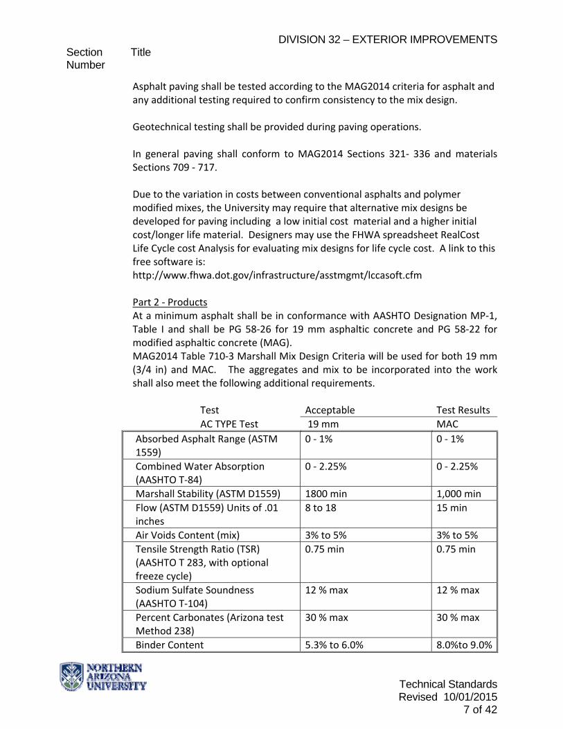
Asphalt paving shall be tested according to the MAG2014 criteria for asphalt and any additional testing required to confirm consistency to the mix design. Geotechnical testing shall be provided during paving operations. In general paving shall conform to MAG2014 Sections 321‐ 336 and materials Sections 709 ‐ 717. Due to the variation in costs between conventional asphalts and polymer modified mixes, the University may require that alternative mix designs be developed for paving including a low initial cost material and a higher initial cost/longer life material. Designers may use the FHWA spreadsheet RealCost Life Cycle cost Analysis for evaluating mix designs for life cycle cost. A link to this free software is: http://www.fhwa.dot.gov/infrastructure/asstmgmt/lccasoft.cfm Part 2 ‐ Products At a minimum asphalt shall be in conformance with AASHTO Designation MP‐1, Table I and shall be PG 58‐26 for 19 mm asphaltic concrete and PG 58‐22 for modified asphaltic concrete (MAG). MAG2014 Table 710‐3 Marshall Mix Design Criteria will be used for both 19 mm (3/4 in) and MAC. The aggregates and mix to be incorporated into the work shall also meet the following additional requirements.
Test Acceptable Test Results
AC TYPE Test 19 mm MAC
Absorbed Asphalt Range (ASTM 1559)
0 ‐ 1% 0 ‐ 1%
Combined Water Absorption (AASHTO T‐84)
0 ‐ 2.25% 0 ‐ 2.25%
Marshall Stability (ASTM D1559) 1800 min 1,000 min
Flow (ASTM D1559) Units of .01 inches
8 to 18 15 min
Air Voids Content (mix) 3% to 5% 3% to 5%
Tensile Strength Ratio (TSR) (AASHTO T 283, with optional freeze cycle)
0.75 min 0.75 min
Sodium Sulfate Soundness (AASHTO T‐104)
12 % max 12 % max
Percent Carbonates (Arizona test Method 238)
30 % max 30 % max
Binder Content 5.3% to 6.0% 8.0%to 9.0%

DIVISION 32 – EXTERIOR IMPROVEMENTS Section Title Number
Technical Standards Revised 10/01/2015
8 of 42
All asphaltic concrete and modified asphaltic concrete shall contain a minimum of 1% Portland cement or dry hydrated lime by weight of total aggregate added to the aggregate in a pug mill prior to addition of the binder. The moisture content of the aggregate immediately prior to the addition of the admixture shall be a minimum of 3.0 %. See Section 714 for modified asphaltic concrete specifications.
REQUIREMENTS FOR ANIONIC/CATIONIC EMULSIFIED ASPHALT (revise to include the following for CRS‐2P) CATIONIC RAPID‐SETTING POLYMER‐MODIFIED ASPHALTIC EMULSION, CRS‐2P MATERIAL SPECIFICATIONS FOR CHIP SEAL COATING
Test Description Test Method Min Max
TEST OF EMULSION
Viscosity, SFS @ 122 F D244 125 400
Settlement, 5 days, % D244 5
Storage Stability 1 Day, %
A244 1
Class, Un‐coated Par A502 60
Particle Charge Test D244 +
Sieve Test, % D244 0.30
Oil Distillate, % V of Emulsion
D244 3
Residue by Distillation, % D244 66
Tests on Residue by VACUUM RECOVERY A512
Viscosity, ABS, Poise @ 140 F
D2171 1800 2800
Pen @ 77F, 100g/5 sec, Dmm
D5 40 90
Ductility, 77F, 5 cm/min, Cm
D113 40
Solubility in TCE, % D2042 97.5
Toughness, inch‐pounds (1) 150
Elastic Recovery by means of Ductilometer, %
T301 58
Tenacity, inch‐pounds (1) 110
Polymer Content (by wt. Of solids) %
CAL‐401 2.5
TEST ON RTFO RESIDUE
Aging Ratio, ABS viscosities
D2171 2.5

DIVISION 32 – EXTERIOR IMPROVEMENTS Section Title Number
Technical Standards Revised 10/01/2015
9 of 42
1) Benson method of toughness and tenacity: Scott tester, inch‐pounds @ 77ºF, 20 inches per minute pull. Tension head 7/8" diameter.
2) Upon standing undisturbed for a period of 24 hours, the emulsion shall show no white milky film upon the surface.
3) The base asphalt shall be modified prior to emulsification. 4) The emulsion shall be pre‐certified prior to use. A one‐quart sample each
of the base asphalt and polymer shall be supplied to the agency 10 days in advance to the project start.
MODIFIEDASPHALTICCONCRETE
Modified Asphalt Concrete (MAC) shall consist of a mixture of paving asphalt, modifiers and mineral aggregate which, with the addition of mineral filler and blending sand as may be required, shall be mixed at a central mixing plant in the proportions hereinafter specified to provide a homogeneous and workable mixture.
Modified Asphaltic Concrete (MAC) shall consist of furnishing asphaltic concrete with binder meeting the requirements of either:
Rubberized Asphaltic Concrete (RAC) Polymer Modified Asphalt Concrete (PMA) Polymer Modified Rubberized Asphalt Concrete – Dry Process (PMRAC) SHRP graded PG64‐28TR=(TR+) At the locations shown on the plans in accordance with the following specifications. Within 10 calendar days of notice of award, the contractor shall submit in letterform, the name of the supplier and a type of MAC to be supplied.
Two weeks prior to construction the contractor shall submit three (3) gallons of the modified asphalt binder for testing. Application and testing will be in accordance with MAG 321 as amended by the General Provisions and Special Provisions.
POLYMER REQUIREMENTS
Melt flow rate, dg/min 190 C
D1238 45

DIVISION 32 – EXTERIOR IMPROVEMENTS Section Title Number
Technical Standards Revised 10/01/2015
10 of 42
MATERIAL
BINDER
The asphalt rubber binder in the mix shall comply with MAG 717 and 335 except the rubber shall be type II and the minimum rubber content for RAC shall be 17% as a percentage of total binder. Asphalt cement for all MAC shall meet the requirements of PG 58‐22 as per AASHTO MP‐1 Table I. Polymer shall be Type SBS and shall be 5.5% to 7% of the total binder for PMA. Twenty percent of the modifier for PMA shall be ground tire rubber. The PMA shall be such that the materials conform to the specification requirements. Ground rubber shall be Type II with the following gradation:
Gradation ‐ Ground Rubber (Type II)
Sieve No. % Passing #10 100 #16 70‐100 #30 25‐60 #50 0‐20 #200 0‐5
Binder for Rubberized Asphaltic Concrete (RAC) shall conform to the following specifications:
Parameter Requirement Apparent viscosity, centipoise, 350ºF, Spindle 3, 1500‐6000 Centipoise
20 RPM (ASTM D2196) Penetration, 77ºF, dmm, 100g, 5 sec 25 minimum 90 maximum
(ASTM D‐5) Penetration, 39.2ºF, dmm, 200 g, 60 sec 15 minimum
(ASTM D‐5) Cone Penetration, 77ºF, dmm,150g, 25 minimum 5 sec (ASTM D‐5) Resilience, 77ºF, % 20 minimum (ASTM D‐3407) Softening Point, ºF 135 minimum (ASTM D‐36)
TFOT Residue (ASTM D1754) 75 minimum Penetration Retention, 39.2ºF, %" Haake type viscosity may be substituted for field control

DIVISION 32 – EXTERIOR IMPROVEMENTS Section Title Number
Technical Standards Revised 10/01/2015
11 of 42
Binder for Polymer Modified Asphaltic Concrete shall conform to the following specifications:
Specification: ASTM SPEC. LIMITS
ORIGINAL ASPHALT METHOD MIN. MAX. Penetration, 39.2 F (200g/60 sec), dmm
D5 25
Penetration, 77 F (100g/5 sec), dmm
D5 40 90
Softening point, F D36 180 Flash point, F D92 450
Ductility, 39.2, F (5 cm/min), cm
D113 30
Ductility, 77 F (5 cm/min), cm
D113 100
Viscosity, 275 F, cst D2170 1000
Recovery, 39.2 F, % D113 MOD 60 Solubility in Tricholrethylyene %
D2042 99
AGED ASPHALT (RTFO) METHOD MIN. MAX.
Retained Penetration, 77 F, %
D5 60
Viscosity Ratio, 275 F, % D2170 15 Softening Point, F D36 175 Ductility, 39.2 F (5 cm/min), cm
D113 20
The asphalt binder modifier for the PMA shall contain a minimum of 20% recycled material.
The Polymer Modified Rubberized Asphalt Concrete – Dry Process (PMRAC‐DP) and SHRP graded PG64‐28TR+ shall conform to requirements of Superpave Grade PG64‐28 (AASHTO MP‐1 and MAG Section 335) except as follows: PMRAC‐DP PG64‐28TR+ Test Properties Test Method Specification Specification Scrap whole tire rubber (Type II) content, %, Minimum 17.0 8.0 Trans‐polyoctenamer rubber polymer (TOR), %, Based on the weight of the tire rubber 4.5
SBS Polymer content %, Minimum 2.0
Original Testing

DIVISION 32 – EXTERIOR IMPROVEMENTS Section Title Number
Technical Standards Revised 10/01/2015
12 of 42
COC Flash Point, C, Minimum ASTM D92 232 232
Softening Point, C, Minimum ASTM D36 50 50
Elastic Recovery, 10C, ASTM D6084 10cm, % recovery/1hr, Minimum 55 55
Solubility in Trichloroethylene, ASTM D2042 97.5 97.5 Minimum, %
Dynamic Shear, 64C, 10 rad/sec, AASHTO TP5
G/sin delta, kPa, Minimum 1.00 1.00
G/sin delta, phase angle, degrees, Maximum 75 75
RTFO Residue Testing AASHTO TP5
Dynamic Shear, 64C, 10 rad/sec,
G/sin delta, kPa, Minimum 2.20 2.20
PAV Aging Residue Testing AASHTO TP5
Dynamic Shear, 25C, 10 rad/sec, G/sin delta, kPa, Maximum 5000 5000
Bending Beam Rheometer AASHTO TP5
Creep stiffness, ‐18C, MPa/60 sec, Maximum 300 300
M‐Value, ‐18C, 60 sec, Minimum 0.300 0.300
Aggregate shall conform to Section 710.2.2.
The aggregate gradation will be as follows: Sieve No. Percent Passing 5/8 100 1/2 98 +/‐ 2 3/8 85 +/‐ 7 4 35 +/‐ 7 8 20 +/‐ 5 30 10 +/‐ 5 200 5 +/‐ 2
AGGREGATES CHARACTERISTICS
Combined aggregates shall conform to 710.2.2 except the minimum sand equivalent shall be 65 and at least 85% by weight of the aggregate retained on the #8 sieve shall consist of particles with at least one rough, angular surface

DIVISION 32 – EXTERIOR IMPROVEMENTS Section Title Number
Technical Standards Revised 10/01/2015
13 of 42
produced by crushing.
MINERAL FILLER AND ANTI‐STRIPPING AGENT
Mineral filler and anti‐stripping agent shall be as per Section 710.2.3.
MIX DESIGN REQUIREMENTS
The provisions of 710.3 MIX DESIGN REQUIREMENTS shall apply to MAC except that:
References to asphalt, liquid asphalt, bituminous cement shall be changed to "binder conforming to 714.2.1."
For estimating purposes, the percentage of binder in the MAC shall be 8% for PMA and RAC. For estimating purposes, the percentage of binder in the MAC shall be 7% for TR+ and for PMRAC‐DP. The exact amount of binder in the MAC shall be subject to the Engineer's approval after review of the contractor's job mix formula and materials submittals. Marshal mix design criteria will be used for MAC.
PRODUCTION TOLERANCES
The provisions of 710.4 PRODUCTION TOLERANCES shall apply to MAC except that:
References to asphalt, liquid asphalt, bituminous cement shall be changed to "binder conforming to 714.2.1."
PRODUCTION REQUIREMENTS
The provisions of 710.5 shall apply for MAC except that:
References to asphalt, liquid asphalt, bituminous cement shall be changed to "binder conforming to 714.2.1." Bituminous binder course shall 2" thick, conforming to MAG Specifications Section 710;
Bituminous surface course shall be 2" thick, conforming to MAG Specifications Section 710. Sealer coat shall be applied after completion of laying of asphalt. DP to specify

DIVISION 32 – EXTERIOR IMPROVEMENTS Section Title Number
Technical Standards Revised 10/01/2015
14 of 42
time frame and procedures. Designer to include in asphalt section design.
32 12 19 Asphalt Paving Wearing Courses
Part 1 – General All new asphaltic pavements shall include a wearing course. Part 2 – Products
Quick setting and emulsified asphalt per MAG spec type CRS‐2. Aggregate gradation shall conform to MAG spec table 716‐1 for moderate traffic areas and MAG spec Table 716‐2 for high traffic areas. ADOT specification CM 11 will be considered as an alternate subject to availability of MAG specification material and credit price.
Submit chip sample for testing prior to application. Part 3 – Execution Loose chips shall be swept and removed within a 24‐hour period and again at a later date if required.
Contractor is responsible for protection of all manholes and valve covers. All manholes and valve covers shall be marked with non‐permanent orange paint and protected with cardboard (or equally effective material) prior to chip sealing.
32 12 36 Seal Coats
Part 1 – General Bituminous surfacing shall be used only in exceptional cases. Chipseal is the preferred preservation method. Part 2 – Products Part 3 – Execution
32 12 73 Asphalt Paving Joint Sealants
Part 1 – General Expansion joint filler material is used with asphalt pavements per MAG2014 Sections 321‐336.

DIVISION 32 – EXTERIOR IMPROVEMENTS Section Title Number
Technical Standards Revised 10/01/2015
15 of 42
Part 2 – Products Joint materials shall be in conformance with MAG2014 Section 729
Part 3 – Execution
32 13 00 Rigid Paving
This section includes concrete and pervious Portland cement based concrete pavements.
32 13 13 Concrete Paving
Part 1 – General Concrete Ramps must meet the requirements of the NAU Design Guideline for Campus Accessibility. Submittals Shop Drawings: Submit sections and details where not fully dimensioned on the drawings. Manufacturer's Data: Submit for proprietary products. Mix Design: Prior to pouring any concrete, submit concrete mixes for approval in accordance with Section 03 00 00. Separate mix designs shall be submitted for each type of concrete to be used in the project. Record of Work: Provide record of time and date of placement, temperature, water additions to the mix, and weather conditions. Quality Assurance: For placement restrictions see Division 03 concrete. All materials to conform to Division 03 concrete
Prior to placement of concrete, independent testing lab must confirm subgrade compaction, responsible party shall confirm that the form placement conforms to the survey and is within the tolerances. Reinforcement shall be tied and supported in rebar chairs as approved by the DP. If welded wire mesh is used, support shall conform with plans and specs. The responsible party shall confirm proper placement and spacing between the rebar or weld wire mesh and the

DIVISION 32 – EXTERIOR IMPROVEMENTS Section Title Number
Technical Standards Revised 10/01/2015
16 of 42
forms. Minimum Thicknesses: 1. Sidewalks not Subject to Vehicle Traffic: 4". 2. Sidewalks and Drives Subject to Vehicle Traffic: 6". 3. Structurally Supported Slabs (Such as Over Tunnels): As required to meet potential loading conditions. 4. Loading docks: 8”
Part 2 – Products Reinforcement shall conformance with 03 21 00 Reinforcing Steel. All campus loading docks shall be paved in concrete and reinforced per DP specifications. Provide either welded wire fabric or fibrous reinforcement in concrete. One type is required for all on‐grade slabs. Curbs, gutter and cross pans finished with burlap drag or wood float. Do not plaster surfaces. Immediately after float finishing sidewalks and ramps, slightly roughen the concrete surface by brooming in the direction perpendicular to the main traffic route. Use fine hair fiber‐bristle broom except on inclined slab surfaces provide a coarse, non‐slip finish by scoring surface with a stiff‐bristled broom, perpendicular to the line of traffic. Special Finishes: Do not use special finishes such as colored concrete, exposed aggregate, etc. unless specific approval from NAU Project Manager is obtained. Evaluation will be made on a job‐by‐job basis. Do not use metal nosings on exterior concrete stairs.
Part 3 – Execution Deposit concrete near final position on grade with minimum segregation and without damage of subgrade. Consolidate concrete so that concrete shall fill the forms and be free from rock pockets, bee holes, and honeycombing. Finishing Use equipment designed to spread, consolidate, screed and float freshly placed concrete in one pass, providing well consolidated, homogeneous mixture, requiring minimum of hand finishing to meet surface tolerances.

DIVISION 32 – EXTERIOR IMPROVEMENTS Section Title Number
Technical Standards Revised 10/01/2015
17 of 42
Finished surface tolerances: Tested with 10' straight edge parallel to center line immediately following first float‐ing of surface. Advance straight edge 5'; space under straight edge shall not exceed 3/16". Joints Control joints, 1. Shall have a minimum depth of 1/4 thickness in the concrete or a minimum of ¾ inch. Space at even intervals perpendicular to the path of travel. The jointing pattern shall be equal to the width of the walk or drive to a maximum of 6 feet o.c. on any side or 10 feet for curb and gutter. For small concrete replacements the jointing pattern shall match existing adjacent work. Expansion joints with preformed joint filler in a vertical position, deviating not more than 1/4" from a straight line. Expansion joints shall be installed when abutting existing concrete or fixed structure. Expansion joint material shall be ½” thick and shall extend the full depth of contact surface and shall be at a maximum spacing of 60 foot o.c. Saw Cutting and Patching Joints shall be sawcut or added during placement with a jointing tool to eliminate random expansive cracking of slab surfaces. Sawcutting shall be performed within 24 hours of the slab Curing Required curing practices will be specified by the design professional in the design documents. As is standard practice, contractors will have their curing equipment and accessories ready for use prior to placement of the concrete to ensure prompt curing once the exposed surfaces are finished. Designers will provide for curing options for warm, dry and cold weather. Concrete operations: Curing of the concrete should begin immediately upon finishing the surface. Finishing should not be completed until surface bleeding has stopped and the bleed water has dried immediately after finishing and water film has evaporated from surface. Do not use liquid membrane type on surfaces to receive mortar bed finishes.

DIVISION 32 – EXTERIOR IMPROVEMENTS Section Title Number
Technical Standards Revised 10/01/2015
18 of 42
Field Quality Control / Testing General: All testing, shall be performed by an approved testing laboratory. The following tests and procedures are subject to change during construction at the discretion of the Engineer. Control Tests: Control test of concrete work shall be made at such times and in such manner as directed by the Engineer at the expense of the owner. Each test shall consist of 3 standard 6” test cylinders cast and cured in accordance with ASTM C31 and C172. One cylinder shall be broken at the end of 7 days after placing, one cylinder shall be broken at the end of 28 days after placing, and the remaining cylinder shall be kept for disposition is determined by Engineer. The remaining cylinder will be broken only when the previous test reports indicate unsatisfactory results. Tests shall be made at the time test cylinders are taken, and recorded on the reports to determine the slump, air content, unit weights, and temperature of the concrete. All tests shall be made in accordance with ASTM C39, C138, or C231. Protection Protect fresh uncured surfaces from rain. Cold Weather: Maintain temperature of concrete above 50 degrees F. for minimum five days from placement. No vehicle loads exceeding design loading. No equipment permitted on new pavement until design strength is attained. Engineer to specify cure of 3 to 7 days minimum unless special use / mix.
32 13 13 Concrete Paving
Part 1 – General Part 2 – Products Part 3 – Execution Description This section includes all general concrete paving for pedestrian travel ways or entry features, that do not have special prominence dictating special design finishes. Design Standard A. 6' design width in areas of low pedestrian travel, 8' design width in areas of
high pedestrian travel, including collector walks at residence hall buildings.

DIVISION 32 – EXTERIOR IMPROVEMENTS Section Title Number
Technical Standards Revised 10/01/2015
19 of 42
Paving continuing or connecting major mall travelways (i.e., Tyler Mall), or major/significant building entries shall be of a width justified by traffic volume and aesthetic precedent.
B. All curb cuts, ramps and level transition shall conform to the most recent edition of ANSI "Specifications for Making Buildings and Facilities to, and Usable for, the Physically Handicapped," Arizona Revised Statues, Title 34.
C. Sidewalks that are 5 feet in width or wider should have 6 inches of concrete over 4 inches of base course.
D. Magnesium floated, with a "rosebud" texture. E. Expansion joints 20' maximum in a single run of paving. F. Architectural scoring or joints to be at the same interval as the design width
of the subject travel way. Designers option for widths greater than 8', or walks requiring special design consideration.
G. An additional 3' of width is required for walks that are adjacent to surface parking lots, where the edge facing parking is used as a wheel stop or overhang area.
H. Walk intersection corners shall be rounded and at all grade changes shall have appropriate curb cuts and transitions that allow full handicap accessibility and safety.
I. A minimum 12' radius turn‐around area is required for any dead‐end walk. J. Walks over 8' in width, adjacent to grade changes of over 4 inch, adjacent to
planter beds, walks crossing of vehicular travelways, special entry features or major mall connections or extensions shall also consist of a border/curb design as described in Division 03, Section 03 35 23.
K. Minimum parking stall size is 9’‐0” x 18’‐0”, handicap accessible stalls 11’‐0” x 18’‐0” with a 5’‐0” unload zone.
32 13 16 Decorative Paving No information 32 13 73 Concrete Paving Joint Sealants No information 32 14 00 Unit Paving 32 14 13 Precast Concrete Unit Paving
Part 1 ‐ General Concrete paving stones are the University preference. 2 3/8" interlocking paving stones, in "N.A.U. Triblend" colors. Unit pavers used in walkways shall have bands of "Finetta" I.P.S. Spacing of bands shall be equal to walkway width. (Reference the pedway for example of the above criteria).

DIVISION 32 – EXTERIOR IMPROVEMENTS Section Title Number
Technical Standards Revised 10/01/2015
20 of 42
This section covers unit pavers. Submittals Prior to construction of the sample pavement submit one set of six units each for each type and color of paver required, showing full range of colors and textures. A materials palette was established for use for all new construction as part of the campus master planning. Pavers shall be consistent with the materials palette. Materials included in the palette are the only materials allowed for use in the exterior of all new buildings and renovations. Brick, sandstone and stone veneer are the masonry elements described. Along with the acceptable materials list the approved local suppliers for LEED accreditation are listed. For all new and infill masonry pavers adjacent to existing pavement, a 36 square
foot sample pavement (mock up) shall be constructed on site near the proposed
work area to evaluate the selected brick for matching. DP shall require the
contractor to allow for sufficient time for the owner and the DP to evaluation
and approve the proposed pavement.
On new construction, a minimum 36 square foot sample pavement (mock up)
should be constructed to establish the standard of acceptance for all elements of
the work, including but not limited to: curbing and expansion, bond pattern, tie‐
in with other materials and finishes, accessories, etc. The sample panel shall be
approved by the owner and the design professional prior to ordering materials
and commencement of masonry work.
Retain sample pavement (mock‐up) during construction as a standard for judging completed unit paver work. Do not move or destroy mock‐up until work is completed. For roadway applications pavement section should include a concrete subbase for pavers. Consult with geotechnical engineer if the area will see lots of vehicular traffic. Part 2 – Products Paver units shall be whole and undamaged prior to installation. Units that are chipped, cracked, broken or stained are not allowed Provide materials obtained from only one source for each type and color of pavers. Bedding and joint sand shall be clean, non‐plastic, and free from deleterious or

DIVISION 32 – EXTERIOR IMPROVEMENTS Section Title Number
Technical Standards Revised 10/01/2015
21 of 42
foreign matter. The sand shall be natural or manufactured from crushed rock. Limestone screenings or stone dust or lightweight aggregates that do not conform to the grading requirements in Table 1 shall not be used. The sands shall be as hard as practically available. Sound durable particles free from organics, clays, deleterious and foreign matter Use an aggregate base course material per MAG2014 Section 702. Bed Sand shall conform to ASTM C33 and joint sand shall conform to ASTM C144 not more than 1% passing No. 200 sieve. ACCESSORIES Upon recommendation by the geotechnical engineer, a geotextile fabric may be specified for paver installation. Use of fabric is reserved for areas with clay soil or damp conditions. Part 3 – Execution Contact Bluestake before conducting any excavations Excavate the pavement area to allow for the pavers, the bedding sand layer Prepare subgrade soil per the recommendations of the soils report. In all cases, this will include even grading of the area and compaction. The subgrade shall be free from water, clay and rocks. If recommended, provide a geotextile fabric. Install edge restraints per plans Verify location, type, installation and elevations of edge restraints around the perimeter area to be paved. Place an approximately 1‐1 ¼ inch deep sand bed
Lay out work in pattern provided in the plans and specs to minimize cutting. Cut pavers as necessary to fit within the edge retraints. Lay the pavers with consistent spacing for joints and provide an even flat surface with no elevation deviation between pavers of greater than 1/16" will be unacceptable. Pavement tolerance of 3/16" is allowed over a distance of ten feet.
32 14 40 Stone Pavers
Description
DIVISION 32 – EXTERIOR IMPROVEMENTS Section Title Number
Technical Standards Revised 10/01/2015
22 of 42
Generally, the project budget will preclude the use of large areas of stone pavers, however in limited areas and as accents, the material can greatly enhance the overall aesthetic character of the design.
Design Standard Pavers: 1/2 inch minimum thickness, thick‐set. A material should be chosen that is relatively impervious to moisture absorption and has a high degree of slip coefficient. Polished or honed finishes as a major field finish are not acceptable.
32 15 00 Aggregate Surfacing
32 15 13 Cinder Surfacing
Clean cinders are not allowed for anything in the County. Dirty cinders are used for bedding pipes and shading trenches. City calls out cinder sand for curbs stops and valve boxes and allows for ½ inch diameter red and black cinders as rock mulch.
32 15 40 Crushed Stone Surfacing
Part 1 – General Gravel roads shall be constructed with the proper cross section to allow for drainage and maintenance. Use the county lot split standard for sloping of roadway bed and shoulders for emergency and maintenance access driveways.
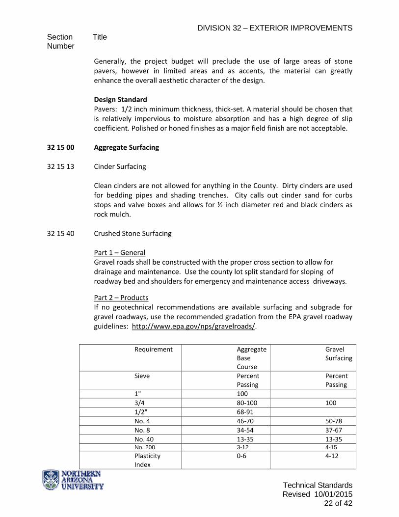
Part 2 – Products If no geotechnical recommendations are available surfacing and subgrade for gravel roadways, use the recommended gradation from the EPA gravel roadway guidelines: http://www.epa.gov/nps/gravelroads/.
Requirement Aggregate Base Course
Gravel Surfacing
Sieve Percent Passing
Percent Passing
1" 100
3/4 80‐100 100
1/2" 68‐91
No. 4 46‐70 50‐78
No. 8 34‐54 37‐67
No. 40 13‐35 13‐35 No. 200 3-12 4-15
Plasticity Index
0‐6 4‐12

DIVISION 32 – EXTERIOR IMPROVEMENTS Section Title Number
Technical Standards Revised 10/01/2015
23 of 42
Part 3 – Execution Contractor to call bluestake before grading the roadway area.
Excavate within the area to allow for driveway material, shoulders, and drainage areas. Scarify and compact the subgrade per MAG2014 Section 301 Install the subgrade ABC per MAG2014 Section 310. Install the crushed stone (gravel surfacing) wearing course per MAG2014 Section 310.
32 16 00 Curbs and Gutters Curbs are used to define the roadway areas and for drainage control. Part 1 – General For concrete curbs Please see NAU Technical Standards, Division 03 Concrete.
Part 2 – Products
Part 3 – Execution
32 16 13 Concrete Curbs and Gutters
Part 1 – General
Part 2 – Products
Part 3 – Execution
32 16 19 Asphalt Curbs 32 17 00 Paving Specialties
No info
32 17 13 Parking Bumpers
Parking bumpers shall be specified for all pavement installations within 2’ of existing structures or fences.

DIVISION 32 – EXTERIOR IMPROVEMENTS Section Title Number
Technical Standards Revised 10/01/2015
24 of 42
32 17 23 Pavement Markings
All roadway pavement markings other than lane striping (bike lane assembly, turn arrows, stop bars, crosswalks, etc.) are to be thermoplastic per ADOT SS704. They may not be painted.
Painted traffic markings to be 4" wide and contain glass beads.
All bike lane assemblies, turn arrows, stop bars, crosswalks, or similar roadway pavement markings that are newly constructed or re‐striped on a chip seal asphalt treatment that is less than 6 months old are to be high visibility preformed tape pavement markings per ADOT Standards. Typical right angle parking stalls are to be installed at a minimum stall size of 9’x18’ and are to be striped on‐center of these dimensions. ADA parking stall sizes, quantities, locations, signage, & paths of travel must adhere to the 2010 ADA Standards for Accessible Design. Each accessible parking stall shall have a surface identification duplicating the following scheme: The NAU CDAD Approved “Accessible Icon” shall be in white on a blue background, and outlined in a white border. A likeness and description of the “Accessible Icon” itself can be found at the following website: http://www.accessibleicon.org. The overall surface identification shall be a minimum 36 inches wide (3’x3’) and shall be aligned with the end of the stall or space adjacent to the traffic aisle so that it is visible to a traffic enforcement officer when a vehicle is properly parked in the space. Marking of Ground or Surface at Access Aisle: The accessible loading and unloading access aisle shall be marked by a border, whereas the painted lines are White and at least 4 inches wide. Within the border, hatched lines a maximum of 36 inches on center shall be at least 4 inches wide and painted Blue. The words "NO PARKING" shall be painted on the ground within each 5‐foot wide loading and unloading access aisle. This notice shall be painted Blue in UPPERCASE letters, no less than 10 inches high, and clearly identifiable as written, and located so that it is visible to traffic enforcement officials. Parking lot striping color schemes: White – Used for vehicle stall lines & motorcycle parking hatched areas Yellow – Hatches used for no parking of any type. Stenciled inside “no parking”. Blue – Hatched Accessible aisles, ADA Stall Lines & Accessible Icons. Stenciled “no parking” inside of hatched areas. Red – Curbs, Fire Lanes, & Hatched Areas anywhere we do not want there to be

DIVISION 32 – EXTERIOR IMPROVEMENTS Section Title Number
Technical Standards Revised 10/01/2015
25 of 42
parking. Typically associated with fire truck access areas. Stenciled “no parking” inside of hatched areas.
32 17 26 Tactile Warning Surfacing
Where ever curb ramps are installed they should comply with the Design Guidelines for universal accessibility. These ramps shall also include a tactile warning area paved using detectable warning/truncated domes in an area determined by the ADA Design guideline requirements. Cast Iron Truncated Dome plates by the Neenah Foundry are the preferred basis of design.
32 18 00 Athletic and Recreational Surfacing
32 18 13 Synthetic Grass Surfacing 32 18 16 Synthetic Resilient Surfacing 32 18 23 Athletic Surfacing Part 1 – General
Part 2 – Products
Part 3 – Execution
**END OF SECTION**

DIVISION 32 – EXTERIOR IMPROVEMENTS Section Title Number
Technical Standards Revised 10/01/2015
26 of 42
32 30 00 SITE IMPROVEMENTS Part 1 – General All site improvements on the campus of NAU shall be designed with sustainability in mind and shall conform to the Design Guidelines for Sustainability.
Part 2 – Products
Products used for site improvements are covered in Sections 31 00 00 and 32 00 00.
Part 3 – Execution
If no direction is given in the plans and specs follow manufacturer’s recommendations or MAG2014 applicable sections.
32 31 00 Fences and Gates
The University has a standard design for the masonry pillar/ornamental iron fence that surrounds the campus. The DP shall obtain this design standard from the Facility Services project manager for projects which require additions to this fence.
32 32 00 Retaining Walls
NAU prefers a dry stack locking material for site retaining walls. Any retaining wall must match the surrounding area where it is built. Submit samples to DP and Owner prior to purchase.
Part 1 – General Part 2 – Products Part 3 – Execution
32 35 00 Screening Devices
Part 1 – General Part 2 – Products Part 3 – Execution
**END OF SECTION**

DIVISION 32 – EXTERIOR IMPROVEMENTS Section Title Number
Technical Standards Revised 10/01/2015
27 of 42
32 80 00 IRRIGATION 32 84 00 Planting Irrigation
Part 1 – General
All irrigation system for new construction shall be designed as part of the landscaping plans and shall be considered in the grading, and stormwater management of the site and the surrounding areas. The design professional shall include adequate irrigation for planting and use reclaimed water for irrigation where it is available.
The contractor will be responsible for all blue staking before and during the project.
Warning Tape: Each 2” line shall have warning tape provided directly above line, 12 inches below finished grade, except 6 inches below subgrade under pavements and slabs. All main lines shall have tracer wires for efficient locating. Provide detectable warning tape (“water” blue for domestic and potable water and “reclaimed” purple for reclaimed water) with metallic core encased in a protective jacket for corrosion protection for irrigation mains, conduit or other underground services outside of building line.
Reduced pressure backflow preventers shall be installed at all connections to water distribution mains. Immediately downstream of the back‐flow preventer shall be a Calsense flow sensor of appropriate size.
Drawings
Prior to construction, preliminary design plans must be submitted to NAU Grounds for approval. At the completion of each project, accurate, reproducable, as‐built drawings will be provided to NAU Ground Department. AutoCad compatible files (*.dwg, *.dxf) will be be provided so the sprinkler system may be entered into the campus infrastructure data.
Part 2 – Products
Pipe and Fittings All pipe used for main lines and auxiliary lines shall be schedule 40 PVC pipe with ratings printed on pipe.
All fittings shall be schedule 40, pressure rated, PVC fittings. Fittings between the auxiliary (lateral) line and any sprinkler head or hose bib shall consist of rigid PVC full circle swing joint. Specifications for piping shall include standards that all piping shall be free from

DIVISION 32 – EXTERIOR IMPROVEMENTS Section Title Number
Technical Standards Revised 10/01/2015
28 of 42
cracks, holes, and foreign materials, blisters, inside bubbles, wrinkles, and dents.
If pipe is stored outside it shall be protected from direct sunlight. No galvanized nipples, elbows, or other fittings shall be used with PVC pipe installations. Standard specifications for the piping materials shall include that the pipe shall be free from cracks, sunburn, discoloration, holes, foreign materials, blisters inside, bubbles, wrinkles and dents. Controllers The controller shall be Calsense ET2000e Irrigation Controller. Flow Sensors shall be Calsense FM Flow Sensors. The master valve will be located in the control box.
Controller Wires Electronic controller cable to be solid copper wire, UL approved for direct burial, minimum gauge 14 UV for runs under 1000 L.F., 12 UF for runs over 1000 L.F. Control wires must be buried at least 18" below finish grade. Electric control wires shall be color coded so that neutrals are white, grass areas are red, shrub areas are blue, flower beds are green and drip irrigated areas are brown. All connections to valves and all splices shall be made with "SNAP‐TITE" connectors and PT‐55 sealer, or approved equal. Valves Valves shall have a minimum size of 1". EFB‐CP Series Rainbird. Ball valves to be installed before all control valves to isolate. Clocks Heads for lawn areas less than 25 feet wide shall be Hunter I 20 or approved equal. Heads for strips and shrubs shall be Rainbird 1800 series., Heads for open areas 25 feet or wider shall be Hunter I 40 or approved equal. Heads for large areas with few trees shall be RAINBIRD SAMS or Hunter I40 or approved equal.

DIVISION 32 – EXTERIOR IMPROVEMENTS Section Title Number
Technical Standards Revised 10/01/2015
29 of 42
Backflow Prevention Backflow preventers shall be reduced pressure type and shall be installed at all connections to domestic water distribution mains. Preferred manufacturers are FEBCO, WATTS or pre‐approved equal. Reclaimed water mains will require pressure reducing valves (PRV). By code, back‐flow preventers must be a minimum of 12 inches above grade. Part 3 – Execution Trenching: Cover Requirements: All pipe and wire under pavement 24" Pressurized Lines 18" Non‐pressurized lines 12" Non‐pressurized drip laterals 8" Control Wire 18"
Lines bordering curbs and sidewalks shall be held 12" away to allow for maintenance and access to the lines. Backfill around and over pipes shall be with sandy soil free from rocks over 1/8" in diameter. Where existing soil does not meet this requirement, sandy soil shall be imported for backfilling. Pipe and control wiring and tubing under walks, roads and other hard surfaces shall be installed in schedule 40 sleeves that are two times the size of the pipe. Sleeves shall extend a minimum of 12" beyond the hard surface. Heads, bubblers, and drip lines shall maintain a minimum of 2' 0" setback from walks, drives or building faces. Special care shall be utilized in design to avoid the possibility of wind driven mist from wetting paving and building surfaces.
Pipe and Fittings All main lines shall be looped whenever possible so as to improve pressure and flow.
Glued joints shall set for 24 hours before pressure is applied to lines. If pipe is stored outside, it shall be protected from direct sunlight.
PVC joints shall be glued according to manufacturer’s recommendations.
Control Wires

DIVISION 32 – EXTERIOR IMPROVEMENTS Section Title Number
Technical Standards Revised 10/01/2015
30 of 42
Lawn, shrub, flower beds, xeriscape and drip areas shall be valved separately and have separate stations on the time clock. All splices shall be made in valve boxes. All wire runs shall have expansion loops at all corners. Valves All valves shall be EFB‐CP Series Rainbird valves. Avoid locating valves in areas where curbs and walks come together. Main valves should be located, when possible, in a grassed area, five feet from sidewalks curbs, or other traffic areas. Ball valve isolation valve installed before all control valves. Valve boxes shall be set at finished grade with valve stems 4" below top of the box. Each valve box or group of valves shall have a quick connect on the pressure side of the valve. Valves to be separated where possible. All valves shall be placed in valve boxes so to allow access for servicing. 3" of gravel shall be placed under all valves (electric, gate and sectional).
Clocks Clocks shall be mounted outside the buildings or any other proximate built structure. Heads Placement of heads shall be influenced by prevailing wind direction, location of mounds and placement and location of trees. Provide diagrams for all head installation. All lines shall be flushed before the heads are installed. A non‐fading, weather resistant copy of the irrigation diagram and controller name‐label shall be affixed to the inside of the controller cabinet door. The irrigation diagram shall show all valves operated by the controller, valve sizes and type of plantings irrigated.
Backflow Prevention All backflow preventers shall be assembled with pipe fittings and risers of

DIVISION 32 – EXTERIOR IMPROVEMENTS Section Title Number
Technical Standards Revised 10/01/2015
31 of 42
galvanized steel, or copper. Valves and drains shall be placed so the entire system may be winterized. Trenching Immediately downstream of the back‐flow preventer shall be a water meter or flow sensor of appropriate size. Flow sensors shall be 2 feet before and two feet after any joints to insure accurate readings.
1. Main lines shall be a minimum of 24 inches deep; auxiliary lines shall be 4
inches deeper than the bottom of the head being used. 2. Lines bordering curbs, sidewalks or other hard surfaces shall be held 12
inches away to allow for maintenance and access to the lines. 3. Sand shall be used in all trenches as bedding material for all PVC piping and
also used as a covering for all piping. There shall be a minumum depth of 2 inches over the top of all piping.
4. Pipe, drip tubing and control wire being routed under walks, roads or other hard surfaces shall be installed in schedule 40 sleeves.
Warning Tape Provide warning tape in the trench with irrigation lines 12 inches above the line and provide detectable warning tape with metallic core encased in a protective jacket for corrosion protection, detectable by metal detector for irrigation mains, conduit or other underground services outside of building line.
32 90 00 PLANTING
Part 1 ‐ General Designers are encouraged to use plant material in energy conserving, climate ameliorating ways. Combinations of deciduous and evergreen shade trees can do much to mediate weather and climatic extremes.
Designers shall refer to site paving drawings and coordinate size of plant pits so as to not undermine hardscape.
Designers to include specifications so that the landscape contractor shall maintain all planting until accepted. Maintenance operations shall include: watering, mulching, tightening or adjusting of tree ties, resetting plants to proper grade, restoration of irrigation basins, fertilization and weeding. Landscape contractor shall commission the irrigation system prior to acceptance. Replacement materials shall meet all specifications of original materials.

DIVISION 32 – EXTERIOR IMPROVEMENTS Section Title Number
Technical Standards Revised 10/01/2015
32 of 42
All plant materials shall be guaranteed for 1 full year following substantial completion or replacement.
Part 2 ‐ Products Fertilizer shall be commercial Ammonium Phosphate w/an NPK ration of 16‐20‐0. Mulch ‐ Fine Screen Organic Top Dressing shall be composted, well rotted, free of refuse and containing not more than 25% straw or other bedding material. Tree stakes shall be three (3) inch diameter by eight (8) feet long, pressure‐treated Lodgepole Pine, free of any weakening knots or other defect. Stake trees up to 15 gallon size with two (2) stakes. Larger sizes shall be staked or guyed. Guy wire shall be new, 12 gauge, annealed, galvanized. Chafing guards shall be new, 3/4" dia. reinforced rubber or vinyl hose, 12" long (min) or as necessary to protect tree from guy wires. Sod shall be cut, delivered and installed (remove mesh from sod rolls) within a 24 hour period. Cultivate subgrade to a depth of 6" prior to placing topsoil and remove all stones and debris 1" and greater in dia. Place topsoil to a depth of 9" over cultivated subgrade. Topsoil shall consist of equal parts topsoil, sand and fine screened organic mulch top dressing.
Part 3 ‐ Execution Where plant material will be placed in soil beneath existing pavement, especially asphalt pavement, or other condition where soil sterilant or other treatment potentially harmful to plant material may have been applied shall be tested for the presence of any such chemicals or condition. Affected soils shall be treated and/or excavated and disposed of in accordance with local codes. Areas to receive ground cover plants shall be excavated in their entirety to 18" below finish grade and backfilled with backfill mix described above. Planting pit percolation rates to be determined prior to planting in the presence of NAU Grounds representative. After water settling backfill, set plants lower than finish grade to create irrigation basins such that the crown of the root ball shall be 4" lower than surrounding finish grade. Basins shall be as wide as the plant pit. Top of rootball shall be flush with finish grade of the basin.

DIVISION 32 – EXTERIOR IMPROVEMENTS Section Title Number
Technical Standards Revised 10/01/2015
33 of 42
2" of mulch shall be incorporated into the top 3" of soil in irrigation basin areas. Where existing lawns have been damaged by construction and are to be repaired by the contractor, follow these instructions: Loosen compacted soil to a depth of 9" min. Remove debris and rock larger than 1" and all contaminated soil. Add topsoil to the level of original grade and allow for settlement. Rototill into the top 6" a 3" layer of fine screened organic mulch top dressing, 2 pounds Ammonium Phosphate (16‐20‐0). Plant NAU approved grass seed (99% pure, 85% minimum germination) at the rate of three pounds per 1000 sf and cover with a thin layer of fine screened organic mulch top dressing. The contractor is required to provide a seed bag tag submittal for review and approval prior to installation which includes at a minimum the Purity %, Test Date, Germination Rate, and Weed Seed Content. Maintenance for new or reestablished turf areas shall be as follows: Maintenance period shall be for 1 year. New sod shall be mowed in ½” increments. Spray heads shall be initially set at finish grade. During the warranty period additional height adjustments by the contractor at no additional cost may be required once turf is established. Irrigation shall not result in wilting, puddles or runoff. After 3 weeks and again at the end of the maintenance period, fertilize with a fertilizer that provides one pound available Nitrogen per 1000 sf. Final acceptance will occur with a satisfactory stand of grass (solid, healthy growth, without bare spots) at the end of the maintenance period.
Berms and swales shall be formed as continuous, smooth landforms with no obvious top or bottom to slopes or grade change from berm to swale. Provide positive drainage away from buildings and structures. Direct runoff water to planting areas.
32 91 00 Planting Preparation

DIVISION 32 – EXTERIOR IMPROVEMENTS Section Title Number
Technical Standards Revised 10/01/2015
34 of 42
32 91 13 Soil Preparation
Part 1 – General
Part 2 – Products Topsoil Topsoil shall be friable, loam topsoil, free from sticks, stones over 1" in diameter, roots, refuse, noxious weeds or any other material toxic to plant growth.
Shall have:
Loam and soil texture (USDA classification) 30% to 50% sand 10% to 25% clay 30% to 50% silt
PH. ‐ 6.0 ‐ 7.5 All in‐place soil and topsoil shall be free from nut grass, refuse, roots, noxious weeds, or any material toxic or a hinderance to plant growth. Unless otherwise specified, all in‐place and/or imported soil will be prepared and conditioned as topsoil to meet the following minimum specifications:
PH shall not exceed 7.5 or lower than 6.0
Electrical conductivity (ec) shall be less than 4.0 milliohms per centimeter as measured on the saturation extract.
Sodium absorption ratio of less than 5 as measured on the saturation extract.
Shall contain approximately 1.5%, by dry weight, organic matter either natural or added.
Soil gradation shall be in accordance with the IBC and the City of Flagstaff Engineering Design and Construction Standards and Specifications.
Any use of manure as a soil conditioner is not acceptable.
All planted areas shall be conditioned by spreading evenly, over the areas, and thoroughly incorporating (rototilled) into the soil to a depth of 6 inches the following material, per 1000 square feet:
20 lbs of 6‐20‐20 commercial fertilizer.
3 cubic yards of nitrogen stabilized amendment derive from redwood sawdust, fir sawdust or finely ground bark.
Part 3 – Execution

DIVISION 32 – EXTERIOR IMPROVEMENTS Section Title Number
Technical Standards Revised 10/01/2015
35 of 42
The contractor may be required to furnish the University at no additional cost, a numerical analysis and test from a soils laboratory for imported materials which will include:
Nitrogen
Phosphorus
Potassium
Electrical conductivity (ec)
Sodium absorption
PH
Percentage of sand, silt, clay, organic matter, water holding capacity
Landscape or planting areas shall not be cultivated when they are so wet as to cause excessive compaction or so dry as to cause excessive dust or the formation of large clods. If existing topsoil is to be used, it should be filled to 3” depth and graded. If imported soil is specified the existing soil shall be scarified to a minimum depth of 8 inches prior to placing topsoil. All clods and rocks over 1 inch in diameter, within 6 inches of the surface, shall be removed and disposed of offsite. The thickness of the topsoil shall be at least 4 inches.
32 91 19 Landscape Grading 32 91 19.13 Topsoil Placement and Grading
NONE Found
**END OF SECTION**

DIVISION 32 – EXTERIOR IMPROVEMENTS Section Title Number
Technical Standards Revised 10/01/2015
36 of 42
32 92 00 TURFS AND GRASSES
Part 1 – General No more than 10% of the area around newly constructed facility shall be turf or other type of water intensive vegetation.
Lawns shall be specified only where maintainable with full normal access (no inner courtyards not directly accessible from outside) for irrigation, mowing, fertilizing, and pest control operations. Lawn areas shall be designed open and clutter free, as far as practical, shrubs and ground cover areas shall be separated by concrete, exposed aggregate, 6"x 6" or greater treated timbers or occasionally brick headers, their tops being 1/2 inch above sod/soil level. Lawn grass shall not be used in any planting strip less than 36" wide unless it has an extension of a continuous larger area. Lawn soil surfaces shall be constructed 1/2 inch below walks, curbs, mow strips or other adjacent paving. Any valve boxes installed in turfed areas shall be made flush with the finish grade not turf height. Single isolated posts in lawn areas shall be fitted with a concrete mow strip at least 6 inches wide around the post.
Part 2 – Products
32 92 22 Hydroseeding
Part 1 ‐ General Hydroseeding must be approved by the Director of Operations and the Grounds Supervisor. Part 2 – Products The preferred grass seed mix is a perennial rye/bluegrass mix. Submit species for approval. Reference page 77 of the Landscape Master Plan for the specific locations and types of grasses required. Different campus areas referred to as different “NAU Zones” in the master plan require different products. Any wildflower seed mix shall be submitted to the NAU Facility Services Grounds division prior to specifying.
DIVISION 32 – EXTERIOR IMPROVEMENTS Section Title Number
Technical Standards Revised 10/01/2015
37 of 42
Part 3 – Execution Lawns may be established cut sod or by hydroseeding. In either case the soil shall be thoroughly rototilled and leveled to receive the grass. All specified hydroseeding must be in place prior to August 1 and protection must be provided for 1 year.
32 92 23 Sodding
Part 1 ‐ General NAU prefers the placement of sod for turf areas when budget constraints allow. Part 2 – Products Sod will be a bluegrass/perennial rye mix. It will come from an area with similar climate and soil conditions to the University. Sod grown on a sandy loam soil will not be accepted. Part 3 – Execution Lawns may be established cut sod or by hydroseeding. In either case the soil shall be thoroughly rototilled and leveled to receive the grass. All sod must be in place prior to September 1 and warranty must be provided for 2 years from the date of substantial completion.
32 93 00 Plants 32 93 43 Trees, Plants and Ground Covers
Part 1 – General All planting shall be guaranteed by the Contractor for a minimum of one year after substantial completion. All specified planting materials shall be of species that have a proved history of resilience in the Northern Arizona locale. Preference shall be given to designs that center around a xeriscape approach and utilize drip irrigation. NAU permits many tree, shrubs, ground covers and flowers to be used for landscaping purposes. Plant selected for landscaping are either included on the focus plant material list or on the permitted list. Designers should not specify or permit the substitution of materials that do not appear on the approved lists.

DIVISION 32 – EXTERIOR IMPROVEMENTS Section Title Number
Technical Standards Revised 10/01/2015
38 of 42
Part 2 – Products The following trees and shrubs have been identified and labeled as focus plant material to be utilized in campus planting:
Trees
Acer Platanoides Red Maple Malus Flowering Crabapple Pinus nigra Australian Black Pine
Picea Pungens Colorado Blue Spruce Populus Tremuloides ‘Kaibab’ Kaibab Aspen Robina pseudoacacia Black Locust Shrubs
Fallugia paradoxa Apache Plume Juniperus spp Juniper Mahonia aquifolium Oregon Grape Pinus mugo mugus Dwarf’ Mugo Pine Potentilla Fruticosa Potentilla Rhus spp Sumac Ribes spp Currant iburnum Opulus Snowball Viburnum The following trees and shrubs may be utilized on campus with the approval of the Manager of Planning and Design and the Grounds Supervisor: Acceptable Plant Material (Trees) Abies Concolor White Fir Abies Lasiocarpa Arizonica Corkbark Fir Acer ginnala Amus Maple Acer Saccharum Sugar Maple Acer Negundo Boxelder Acer Saccharinum Silver Maple Betula Pendula European White Birch Fraxinus Americana American Ash Catalpa spp Catalpa Fraxinus Pennsylvanica Green Ash Gleditsia Tracanthos Honeylocust Picea Abies Norway Spruce Picea Engelmannii Englemann Spruce Pinus Aristata Bristlecone Pine Pinus Flexilis Limber Pine

DIVISION 32 – EXTERIOR IMPROVEMENTS Section Title Number
Technical Standards Revised 10/01/2015
39 of 42
Pinus Sylvestris Scotch Pine Platanus spp Sycamore Populus Tremuloides Quaking Aspen Prunus spp FloweringPlum Prunus spp Flowering Cherry Pseudotsuga Menziesii Douglas Fir Pyrus Calleryana Bradford Flowering Pear Quercus Gambelli Gambel Oal Quercus Rubra Northern Red Oak Salix matsudana Globe Willow
Sequoidendron Giganteum Giant Sequoia Tilia spp Linden
Acceptable Plant Material (Shrubs) Agave spp Agave
Amelanchier spp Serviceberry Amorpha fruticos Indigo Bush Berberis thunbergii Japanese Barberry
Chamaebatiaria millifolium Fernbush Cowania Mexicana Common Cliffrose Forsythia Intermedia Dwarf Forsythia Ligustrum Vulgare Privet Locicera Involucrata Twinberry Honeysuckle Robinia neomexicana New Mexico Locust
Rosa spp Rose Rosa woodsii Wild or Woods Rose
Spiraea spp Spirea Yucca spp Yucca
Acceptable Plant Material (Groundcovers)
Scientific Name Common Name Delosperma nubigenum Ice Plant Lonicera arizonica Arizona Honeysuckle Partheocissus quinquefolia Virginia Creeper Sedum spp. Stonecrop
Acceptable Plant Material (perennial flowers) Scientific Name Common Name Archillea spp. Yarrow Berlandiera lyrata Chocolate Flower Campanula Glomerata Clustered Bellflower Cetnranthis ribber Red Valerian Chamaemelum Nobile Chamomile

DIVISION 32 – EXTERIOR IMPROVEMENTS Section Title Number
Technical Standards Revised 10/01/2015
40 of 42
Clematis spp Clematis Coreopsis spp Coreopsis Eschscholzia californica California Poppy Gaillardia grandiflora Blanket Flower Sempervivum tectorum Hens and Chickens Geum triflorum Old Man’s Whiskers Hemerocallis spp DayLily Ipomopsis aggregate Skyrocket Iris spp Bearded Iris Linum perenne Blue Flax Lupinus spp Lupine Kniphofovia uvaria Red hot Poker Oenthera caespitosa Tuft Evening Prim‐rose Oryzopsis hymenoids Indian Rice Grass Penstemon spp. Beardtongue Phlox spp Phlox Potentilla spp. Cinquefoil Ratibida columnifera Mexican Hat Salvia spp Sage Thymus spp. Thyme Zinnia grandiflora Prairie Zinnia
Acceptable Plant Material (Flowers) The flower list subject to approval of the Director of Operations and the Grounds Supervisor. Trees and Shrubs All specified tree and shrub plant material must be in place prior to August 1. All plant materials used shall be of types proven hardy for the area and situation. New, novel or "different" plants shall be restricted to a bare minimum. All plants shall be healthy, true to name and full size of specifications (no recent shifts to larger container). The minimum caliper size for new trees shall be 2 inches. Trees planted in lawns shall be provided with 24 inches of bare, sod free soil beyond and around the full circle of the tree. This area shall also be depressed (dish shaped) to help deep watering of the tree. Deciduous trees shall be planted no closer than 8 feet from any walk or drive and evergreen trees planted no closer than 2 feet greater than the anticipated mature radius of branching. Trees planted in rows shall be uniform in size and shape. Trees and shrubs shall not be planted until all construction working the area has

DIVISION 32 – EXTERIOR IMPROVEMENTS Section Title Number
Technical Standards Revised 10/01/2015
41 of 42
been completed, final grades established, the planting areas properly graded and prepared as specified.
Part 3 – Execution
Temporary Protection Provide temporary fencing, barricades or guards to protect from damage existing trees, lawn, and other plants which are designated to remain on site. Protect root systems by not storing construction materials, debris, or excavated material within five (5) feet of the drip line of the tree (outer perimeter of the branches). Do not permit vehicle traffic within stated area and restrict foot traffic to prevent excessive compaction of the soil over root systems. Repair and Replacement of Trees, Shrubs and Lawn Repair trees, shrubs and lawns damaged by construction in a manner acceptable to the Landscape Architect and/or the Facility Services Grounds Supervisor. Make repairs promptly after damage occurs to prevent progressive deterioration of damaged trees, shrubs, and lawns.
Remove and replace dead and damaged trees, lawns, and shrubs, which are determined by the Grounds Supervisor to be incapable of restoration to normal growth patterns. Provide new trees of same size and species, unless such plant is on the "DO NOT PLANT" list. Plant and maintain as specified under landscaping section of the specifications. For any trees requiring replacement due to neglect by the contractor that have a caliper greater than 4", a penalty of $1,000.00 per tree will be assessed. Dig plant pocket for trees a minimum of 24" wider and 6" deeper than root ball, unless otherwise specified. Dig plant pocket for shrubs a minimum of 12" wider and 6" deeper than root ball, unless otherwise specified.
Loosen subsoil to a depth of 4". Loosen earth on sides of pocket to break the glaze caused by digging. Set plants at finished grade. Fill prepared soil to 1/2 the depth of ball, pack firmly, and settle with water.
If balled and burlapped, loosen and remove burlap and all lacing and remove

DIVISION 32 – EXTERIOR IMPROVEMENTS Section Title Number
Technical Standards Revised 10/01/2015
42 of 42
wire baskets from root ball. Absolutely no packaging material is allowed to be left with the tree. . Backfill with prepared soil which, after compaction, is flush with ground level. Cover plant pocket area with 3" to 4" of mulch. Prune, wrap and brace as specified.
32 94 00 Planting Accessories
Part 1 – General
Part 2 – Products
Part 3 – Execution
32 96 00 Transplanting
Part 1 – General Salvage of existing trees from a project shall be performed by a firm approved by the University and with at least four years experience with this type of work. The work shall be guaranteed and conducted in a manner consistent with local practice. The University shall designate a holding area and source of irrigation for boxed or otherwise temporarily stored trees. NAU Landscape has first right of refusal for all plantings or materials removed or transplanted from the site. Contractor is required to provide the NAU Landscape department and NAU Project Manager a minimum 72 hours’ notice prior to any site removals or anticipated transplants.
Part 2 – Products No specific products included. Part 3 – Execution Transplanting of plant materials shall be consistent with the execution section of 32 90 00.
32 96 33 Shrub and Tree Transplanting
All trees and shrubs shall be container grown, not balled and burlap, unless otherwise approved by NAU Grounds Department.
**END OF SECTION**