division 23 heating, ventilation, and air conditioning · a. heating, ventilating, and...
TRANSCRIPT

Division 23 - Heating, Ventilation and Air Conditioning
University of Minnesota Standards and Procedures for Design
December 2012
1 of 164
Division 23 – Heating, Ventilation, and Air Conditioning
Table of Contents
23 00 00 HVAC
23 00 01 Scope
23 00 02 Prohibited Items
23 00 03 Codes
23 00 04 Design Intent Report/Basis of Design
23 00 05 Coordination with University of Minnesota Department
23 00 06 Access for Maintenance
23 00 07 Mechanical Specifications
23 00 08 Mechanical Drawings
23 00 09 Coordination with Other Trades
23 00 10 Materials, Manufacturers, and Suppliers
23 00 11 Equipment Bases
23 00 12 Painting
23 00 13 Existing Facilities
23 00 14 Building Service Outages
23 00 15 Mechanical Equipment Rooms, Penthouse Access
23 00 16 Operating Instructions
23 00 17 Energy Information
23 00 18 Energy Conservation and Sustainability
23 00 19 Industry Standards
23 00 20 Welding and Brazing
23 00 21 Electrical Requirements
23 00 22 Excavation and Backfill for Underground Mechanical Work
23 00 23 Equipment Isolation
23 00 24 Equipment and System Cleaning
23 00 25 Basic Tunnel Requirements
23 00 26 Tunnel Communication Cable Installation – UTY
23 01 30 Operation and Maintenance of HVAC Air Distribution
23 01 60 Operation and Maintenance of Central Cooling Equipment
23 05 13 Common Motor Requirements for HVAC Equipment
23 05 16 Expansion Fittings and Loops for HVAC Equipment
23 05 19 Meters and Gages for HVAC Piping
23 05 23 General-Duty Valves for HVAC Piping
23 05 29 Hangers and Supports for HVAC Piping and Equipment
23 05 53 Identification of HVAC Piping and Equipment
23 05 93 Testing, Adjusting, and Balancing
23 06 00 Schedules for HVAC
23 07 00 HVAC Insulation
23 07 13 Duct Insulation
23 07 16 Equipment Insulation
23 07 19 Piping Insulation
23 08 00 Commissioning of HVAC
23 09 00 Instrumentation and Controls for HVAC
23 21 13 Hydronic Piping and Heating Piping

Division 23 - Heating, Ventilation and Air Conditioning
University of Minnesota Standards and Procedures for Design
December 2012
2
23 21 23 Hydronic Pumps
23 22 00 Steam and Condensate Piping and Pumps
23 25 00 HVAC Water Treatment
23 30 00 HVAC Air Distribution
23 57 00 Heat Exchangers for HVAC
23 60 00 Central Cooling Equipment
23 64 00 Packaged Water Chillers
23 65 00 Cooling Towers
23 73 00 Indoor5 Central-Station Air-Handling Units
23 74 00 Packaged Outdoor HVAC Equipment-Rooftop Air Conditioners
23 75 00 Compressed-Air Systems

Division 23 - Heating, Ventilation and Air Conditioning
University of Minnesota Standards and Procedures for Design
December 2012
3
23 00 00 Heating, Ventilation and Air Conditioning (HVAC)
23 00 01 General: The HVAC specifications shall be properly coordinated with
Division 01 00 00 - General Requirements and other divisions, and shall
conform to the format and organizational requirements stated in the
introduction of these standards.
.
23 00 02 Scope: This division covers the following mechanical systems:
a. Heating, Ventilating, and air-conditioning (HVAC), including, all ducting, air handling
equipment, all supply, return, and exhaust fans, all heat recovery equipment and any other air
flow equipment for buildings environmental controls
b. All HVAC equipment piping
c. All ventilation for research related equipment
d. All bio-tech related piping
e. Steam distribution and individual applications
f. Chilled water and glycol distribution and individual applications
g. Hydronic heating distribution and individual applications
h. Compressed air generation and distribution for the laboratory applications
i. All process piping for all research related equipment
j. All piping in utilities tunnels and shafts.
k. All direct buried piping for all utilities, including the factory insulated steam and condensate
piping.
l. 23 00 02 Prohibited materials and practices:
Where applicable, individual sub sections include the prohibited materials and installation
practices.
23 00 03 Codes: All work shall meet all applicable U of M, local, state and national codes and
standards.
23 00 04 Design Intent Report/Basis of Design:
Architect/Engineer (A/E) shall provide a design intent report at the preliminary design phase that
documents the following:
a. Energy conservation measures and energy requirements for the proposed
facility.
b. Noise criteria
c. Choice of equipment with life cycle cost analysis
d. Variances to the codes and standards
e. B3, SB-2030 and/or LEED compliance measures when required.
f. 50 year design considerations and its impact on mechanical equipment
selection. Most mechanical equipment has a 25 years life.
g. Alternates and proposed value engineered construction materials and
construction methods.
23 00 05 Coordination with University of Minnesota departments.

Division 23 - Heating, Ventilation and Air Conditioning
University of Minnesota Standards and Procedures for Design
December 2012
4
05.1. The architectural and engineering consulting firm (A/E) shall coordinate with the following
departments to ensure that the users needs are satisfied:
1. Facilities Management (FM)
2. Board of Regents
3. U of M Building Code Office
4. Capital Project Management (CPM)
5. Office of Classroom Management (OCM)
6. Department of Environmental Health and Safety (DEHS)
7. Disability Services
8. Facility Support
9. Food Service
10. Parking and Transportation Services (PTS)
11. Central Security
12. Office of Information Technology (OIT)
13. University of Minnesota Policy Department (UMPD)
14. Energy Management and University Planning
15. Operations and Maintenance
16. District offices
The A/E shall also coordinate with the University Utility Group to determine availability of steam, chilled water, compressed air, and 13.8 KV electrical feed for connection to campus utility systems.
05.2. The architect shall work with the mechanical engineer to ensure that the equipment
installation meets the architectural requirements of the building. All mechanical equipment shall
be located inside the building except cooling towers and rooftop air handling equipment.
05.3. Building air intakes shall be located a minimum of 30 feet above the grade or on the roof.
On buildings less than three stories high, location on the roofs shall be allowed. All ground level
air intakes shall be reviewed and approved by the Facilities Management.
23 00 06 Access for maintenance
06.1. Location of equipment shall be determined by its service need, so it can be easily
maintained. In mechanical spaces, when the equipment is located 6 feet or higher above the
ground, a service platform shall be provided that complies with
M N OSHA requirements for service and maintainability. The A/E shall provide sectional
drawings of the mechanical rooms and shall meet with the district (Facilities Management) early
in the design phase. For all equipment on flat and pitched roofs, access, safety and service
platforms shall be provided per MN OSHA and MN building codes.
06.2. The A/E shall coordinate the mechanical design with other disciplines to provide
adequately sized and properly located access panels.
06.3. If below ground pits are required, these shall be minimum 6’x6’ with permanent ladders,
gratings, and railings, a minimum 20 A GFI outlet, and a floor drain. These shall be reviewed
with the DEHS for the confined spaces and properly labeled.

Division 23 - Heating, Ventilation and Air Conditioning
University of Minnesota Standards and Procedures for Design
December 2012
5
23 00 07 Mechanical Standards: Mechanical standards shall be properly
coordinated with the CSI sections of Section 01 00 00 - General Requirements and other
sections, and shall conform to the format and organizational requirements stated in the
Introduction of this manual.
23 00 08 Mechanical Drawings: Mechanical drawings shall be clearly delineated at
appropriate scale to accurately define piping, ductwork and equipment. The A/E shall provide
coordination drawings when necessary. These are different than the construction coordination
drawings, normally in 3d format.
23 00 09 Coordination with other trades
09.1. Mechanical systems shall be coordinated with the building design and construction, as well
as with electrical, plumbing, fire protection, temperature controls, and other systems to eliminate
construction conflicts.
23 00 10 Materials, Manufacturers and Suppliers
10.1. Whenever possible, equipment specified and provided shall be of a type and manufacturer
that has a local representative and a local replacement and service outlet to give complete
coverage on parts and service at all times.
10.2. All factory-assembled equipment shall incorporate materials and fabrication methods
consistent with these standards and shall meet all MN codes including but limited to welding and
pressure piping.
23 00 11 Equipment Bases: Concrete bases with a 4-inch minimum height shall be
provided under all floor-mounted mechanical equipment. The concrete base height shall be
adequate to accommodate condensate ‘P’ traps and proper condensate flow. Base size and
location shall be coordinated with the equipment specified and shall be shown on the
architectural and structural drawings. Mechanical equipment shall be installed using vibration
isolators. The vibration isolators shall be per equipment manufacturer’s recommendations. No
isolation to the floor is needed for slab on grade.
Concrete bases for equipment requiring isolation pads shall be designed, reviewed and approved
by the final user of the equipment.
23 00 12 Painting
12.1. All piping, ducts, radiation, grills, diffusers and other equipment that is exposed in finished
and unfinished spaces shall be painted in accordance with Division 09 91 00 under finishes.
12.2. Painting of exposed piping, ducts and other equipment in the equipment spaces, tunnels,
crawl spaces, shafts, and other unfinished spaces shall be included in the mechanical
specifications. See Division 09 91 00 under finishes.
23 00 13 Existing Facilities: For remodeling projects, the University of Minnesota shall

Division 23 - Heating, Ventilation and Air Conditioning
University of Minnesota Standards and Procedures for Design
December 2012
6
provide openings in walls and ceilings where required and where the A/E requests to permit
verification of existing piping, ductwork and equipment.
23 00 14 Building Service Outages: The A/E shall coordinate this requirement with the
Preconstruction Meeting Agenda form located in the Forms Section.
14.1. Service Outage Request: The contractor shall request all building service outages through
the Project Manager. All outages shall be accommodated Monday thru Thursday unless
otherwise requested by the Project Manager. The contractor shall give 2 week notice to the
Project Manager for any planned service outages.
14.2. Impairment Procedures: Request for impairments of fire protection system or fire alarm
system requires a 24-hour notice. Refer to Division 21 00 00 - Fire Protection Systems and
Division 21 30 00 - Fire Pumps for specific impairment procedures.
14.3. Fire Safety Precautions
14.3.1. The A/E shall include the following statement in the specifications with regard to
protective measures for the contractor during grinding, cutting, brazing, sweating or
welding operations.
14.3.1.1. All grinding, cutting, brazing, sweating or welding operations carried on
in the vicinity of, or accessible to combustible material, shall be adequately
protected to make certain that a spark or hot slag does not reach the combustible
material and start a fire.
14.3.1.2. When it is necessary to do grinding, cutting, brazing, sweating or welding
close to wood construction in pipe shafts or other locations where combustible
materials cannot be removed or adequately protected, employ fireproof blankets and
proper fire extinguishers. A helper shall be stationed nearby to guard against sparks
and fire.
14.3.1.3. Whenever combustible material has been exposed to molten metal or hot
slag from welding or cutting operations or spatter from electric arc, a fireguard shall
be kept at the place of the work for at least one hour after completion to make sure
that smoldering fires do not start.
14.3.1.4. When welding or cutting in a vertical pipe shaft or floor opening, a
fireguard shall examine all floors below the welding or cutting operation. The
fireguard shall be kept on duty for at least one hour after completion of work to
guard against fires.
14.3.1.5. Before grinding, cutting, brazing, sweating or welding, consult with the
A/E as to particular safety precautions.
14.3.1.6. In the case of a remodeling project in an existing building or connection of
a new building to an existing building, the A/E also shall include in the

Division 23 - Heating, Ventilation and Air Conditioning
University of Minnesota Standards and Procedures for Design
December 2012
7
specifications all the mandatory requirements described in the Standard Operating
Procedures for Hot Works form located in the Forms Section.
23 00 15 Mechanical Equipment Rooms, Penthouse Access
15.1. All equipment rooms shall be properly ventilated to maintain proper operating temperatures
as required by the proper equipment operation.
15.2. Mechanical equipment shall be located, sized and arranged in a space that provides easy
access for maintenance, repair and future replacement. The equipment also shall be enclosed to
separate it from other building functions.
15.3. Where heat-generating equipment is situated adjacent to or above occupied spaces, the
equipment shall be ventilated. In addition, the floors, walls and ceilings shall be insulated with
permanently attached, durable, and fire-resistant insulation to provide a “U” (overall heat transfer
coefficient) value through the wall or ceiling not to exceed 0.15 BTU/hr. sq. ft. °F. The
insulating materials shall be reviewed and approved by the U of M designated representative.
15.4. Adequate provisions shall be made in mechanical space to support equipment, piping and
ductwork.
15.5. Equipment, piping and ductwork in such rooms shall be mounted or suspended in a manner
that will isolate it from the system and from the structure to prevent noise and vibrations in
adjacent spaces.
15.6. No mechanical equipment of any type shall be placed in building areaways or tunnels
without prior approval from the appropriate parties. No piping shall run into or through fresh air
plenums and/or air ducts.
23 00 16 Operating Instructions
16.1. Complete temperature control drawings and operations sequence shall be mounted in a
conspicuous location on or immediately adjacent to major equipment such as air handlers and
converters.
16.2. Refer to Division 01 00 00 - General Requirements, Section 01 70 00 - Contract Closeout
for additional information on equipment maintenance and operations manuals.
16.3. Specifications shall clearly define the responsibilities of the contractor and the
manufacturers to provide instruction to designated university personnel in the proper operation
and maintenance of all mechanical equipment provided. The schedule for the training shall be
coordinated with the Project Manager and the commissioning agent as appropriate.
23 00 17 Energy Information
17.1. The Uof M operates its own central steam, chilled water, central compressed air, and
primary electric distribution systems. For utility services to new buildings or existing buildings

Division 23 - Heating, Ventilation and Air Conditioning
University of Minnesota Standards and Procedures for Design
December 2012
8
being remodeled, contact the University Energy Management Utility section for information on
utility services availability and installation requirements to connect to the central systems.
17.2. Specification for new university buildings shall include a section that identifies the peak
and monthly energy and utility requirements of the buildings. The requirements shall include
electrical, chilled water, gas, steam, compressed air, and water services. Provide both design load
and estimated load.
17.2.1. Electricity
A. Design Load: kWh/month for a 12-month period
B. Design Demand: Peak kW/month for a 12-month period
C. Estimated Load Profile: kWh/month for a 12-month period
D. Estimated Demand: Peak kW/month for a 12-month period
17.2.2. Chilled Water
A. Design Load: Tons of cooling required/chiller size recommended
B. Installed Capacity: Chiller size in tons if a stand alone chiller is required.
C. Design cooling load calculations in tons on a design day
D. Estimated Load Profile: Ton hours/month for a 12-month period
17.2.3. Gas
A. Estimated Load Profile: Therms/month for a 12-month period
B. Design Demand: Peak usage, cubic ft./hr. on a design day
17.2.4. Steam
A. Estimated Load Profile: Steam pounds per month for a 12-month period
B. Design Demand: Peak steam demand in pounds per hour on a design day
17.2.5. Water
A. Estimated Load Profile: Water gallons per month for a 12-month period
B. Design Demand: Gallons/hour maximum
17.2.6 Compressed Air
A. Estimated use in SCFM
B. Designed load in SCFM
23 00 18 Energy Conservation and Sustainability
Refer to the Sustainable Design Standards section (General Information) for energy conservation design
requirements.

Division 23 - Heating, Ventilation and Air Conditioning
University of Minnesota Standards and Procedures for Design
December 2012
9
23 00 19 Industry Standards
In addition to the requirements of the regulatory agencies listed in Division 01 00 00 - General
Requirements, Division 01 41 13 - Building Code Regulatory Requirements, the design and construction
shall conform to the latest edition of the following standards where applicable:
a. American Concrete Institute
b. American Conference of Governmental Industrial Hygienists
c. American Institute of Steel Construction
d. American Society of Heating, Refrigeration and Air Conditioning Engineering
e. American Society of Mechanical Engineers
f. American Society for Testing Materials
g. American Water Works Association
h. American Welding Society
i. ANSI Code for Power Piping B31.1
j. Associated Air Balance Council
k. Hydraulic Institute Standards for Centrifugal, Rotary and Reciprocating Pumps
l. Institute of Electrical and Electronic Engineers
m. National Association of Sheet Metal and Air Conditioning Contractors
n. National Board of Boiler and Pressure Vessel Inspectors
o. National Bureau of Standards
p. National Commercial and Industrial Insulation standards
q. National Environmental Balancing Bureau
r. National Fire Protection Association
s. National Safety Code for Mechanical Refrigeration
t. International Institute of Ammonia Refrigeration
u. ASME BioProcessing Equipment and Piping
23 00 20 Welding and Brazing
20.1. Certified and licensed trades persons shall perform all mechanical welding and brazing.
Certification shall be for the type of work being performed and shall be accomplished in
accordance with the “Qualification Standard for Welding Procedure, Welders and Welding
Operators" as specified by ASME or appropriate governing agency for brazing.
20.2. An independent testing laboratory shall radiograph selected joints, which shall be evaluated
on the basis of API and ANSI construction standards appropriate for the service. The A/E shall
identify the standard applicable for each welded system.
20.3. Steam condensate piping trades persons shall follow procedures identified in the Procedure
Qualification Record and Welding Procedure Specifications in these standards.
20.4 All underground and in tunnels steam and condensate piping welding joints shall be 100%
radiographed.
23 00 21 Electrical Requirements

Division 23 - Heating, Ventilation and Air Conditioning
University of Minnesota Standards and Procedures for Design
December 2012
10
21.1. The A/E shall supplement specifications with the necessary control diagrams for
mechanical equipment. The diagrams shall clearly define the sequence of operation, as well as
the responsibilities of mechanical and electrical subcontractors.
21.2. To ensure that the temperature control system is complete, control wiring for automatic
temperature control systems and other special systems as noted shall be specified in this division.
21.3 All motor starters and disconnects and other electrical components that are not integral part
of the shipped equipment shall be installed and wired by the electrical trade.
23 00 22 Excavation and Backfill for Underground Mechanical Work
22.1. The requirements specified in Division 31 - Earth Work shall be applicable to this work,
including protecting, sheathing and shoring, blasting, compaction filling, compaction testing and
grading.
22.2. Fill at manholes shall be placed in 6-inch lifts and compacted to the standards specified in
Division 31 - Earth Work.
23 00 23 Equipment Isolation
23.1. The specifications shall include isolation valves. All equipment must be installed with
isolation valves for shutoff service. The valves must have flanged or screwed ends. If screwed,
provide a union between equipment and valve.
23.2. All systems such as potable water, heating systems and cooling systems must have a
minimum of one isolation valve per building level.
23 00 24 Equipment and System Cleaning
24.1. The specifications shall include system-cleaning requirements. After hydrostatic tests and
prior to operating tests, equipment, including and not necessarily limited to the chiller, cooling
tower, boilers, heat exchangers and all piping shall be thoroughly flushed and cleaned.
24.2. All piping systems, including open and closed loops, shall be cleaned and disinfected
before they become operational. Exception: Sanitary and storm sewers are not required to be
disinfected. The A/E shall specify that cleaning and disinfecting the system be done by the
university water treatment supplier.
Coordination of the activity with the District is required. Disinfecting shall be done to meet the
minimum requirements that DEHS defines.
24.3. After the solution has cleaned the system, the solution shall be drained and thoroughly
flushed with fresh water from the system. After initial cleaning, the Project Manager or designee
shall sign and certify that the system has been thoroughly cleaned. Any cleaning water that
cannot be drained to the city sewer system shall be removed from the site by the contractor.
23 00 25 Basic tunnel requirements.

Division 23 - Heating, Ventilation and Air Conditioning
University of Minnesota Standards and Procedures for Design
December 2012
11
General: These services and equipment are provided by appropriate contractors.
25.1. Lighting must be equivalent to equipment rooms. Two-lamp fluorescent, surface-mounted,
low profile fixtures that are free from sharp edges are preferred. Pay careful attention to location
to ensure that lighting fixtures do not pose a hazard for head injuries.
25.2. Four-way convenience outlets shall be no farther than 100 feet apart.
25.3. Welding outlets that match existing standard welding outlets shall be no farther than 200
feet apart.
25.4. Provide ventilation. Fresh air sources shall be controlled with manual dampers.
25.5. Surface and groundwater must be drained to the nearest storm sewer. Drainage pipes and
trenches must be designed so that trash, sand, mineral deposits and other debris can be easily
removed.
25.6. Secure all access points by padlock or key lock or electronic card entry. Full-sized doors
require panic hardware. Dampers may be provided on doors for ventilation.
25.7. Designers shall contact University Energy Management Utility Section personnel regarding
specific design requirements for equipment that detects intrusion into tunnels and steam system
sensors.
23 00 26 Tunnel Communication Cable Installation.
1. General: This section covers standards for planning and installing all communication cable in the
steam tunnels on the Minneapolis and St. Paul campuses. This standard covers cable installations by any
university department and outside contractors. These services and equipment are provided by
appropriate contractors.
2. Planning
2.1. New cable installations shall go through a planning stage. The installing
department/contractor shall show the locations of all new cable on a scalable drawing. Drawings
shall be submitted to the building code official's office and University Energy Management for
approval prior to installation. Drawings shall be submitted at least two weeks before the planned
start of construction. Drawings shall include sections that detail precisely where the cable is to be
routed. Drawings shall clearly point out locations where headroom or other safety compromises
cannot be avoided.
2.2. Because there are numerous existing tunnels with varying needs for cable installation, it is
impractical to create details on standard installation layout. Where there is doubt, contact
University Energy Management for the best routes for new cable installation.

Division 23 - Heating, Ventilation and Air Conditioning
University of Minnesota Standards and Procedures for Design
December 2012
12
3. Installation
3.1. The Building Officials Office and University Energy Management shall approve the
drawings before cable installation.
3.2. Cable installation shall be done in as safe and professional manner as possible.
3.3. New installation shall not create unnecessary safety hazards.
3.4. Headroom shall be maintained at all times in all locations.
3.5. Install cables where they will not interfere with existing mechanical equipment, existing
lighting and electrical power equipment, ladders and tunnel carts.
3.6. Cable installation shall be free of sharp edges.
3.7. Remove unused cable at the earliest possible time.
3.8. Place tags with installation date and responsible party on the cable every 200 feet and at
every juncture and turn.
23 01 30 Operation and Maintenance of HVAC Air Distribution
30.51 HVAC Duct Cleaning
When duct cleaning is necessary, refer to Appendix II - HVAC System Decontamination: Duct
Cleaning.
For all new construction, all HVAC ducts shall be cleaned prior to the
commissioning of HVAC equipment and acceptance of the mechanical work.
For all remodeling, all ductwork shall be cleaned as required and as directed by
the A/E and the District’s personnel.
23 01 60 Operation and Maintenance of Central Cooling Equipment
60.71 Refrigerant Recovery/Recycling
For all new and remodeling work, special attention shall be provided to eliminate any leaks and
accidental discharge of any refrigerant to the atmosphere. All refrigerants shall be recovered and
recycled per local and national standards and codes. The recovered refrigerant are the property
of the U of M. These shall be saved or discarded by the contractor as directed by the U of M
authorized personnel.
23 05 13 Common Motor Requirements for HVAC Equipment
Design ‘E’ motors are prohibited
Division 23 - Heating, Ventilation and Air Conditioning
University of Minnesota Standards and Procedures for Design
December 2012
13
All electrical motors up to and including 0.5 HP shall be 115-1-60. All motors above 0.5 HP
shall be 460-3-60 or 208-3-60. All three phase motors shall be dual voltage; 208/230 and 460
volts.
All electrical motors shall be of high efficiency, 1.1 service factor.
All motors located inside the air handling equipment shall be TEFC.
All motors located in the ambient shall be protected from rain
All motors shall meet the minimum requirements of all applicable Energy codes,
and standards.
23 05 16 Expansion Fittings and Loops for HVAC Equipment
1. Wherever practical, show details for properly designed expansion loops or piping offsets to
compensate for thermal expansion in the piping system. A structural engineer shall design
anchors and guides for expansion loops and joints as required. Show details for the anchors and
guides on the drawings. A structural registered engineer’s signed design calculations shall be
submitted for review.
2. Expansion compensators in hot water systems shall be Flexonics Model H or the U of M
approved equal. The compensators shall incorporate guides and anchors.
3. Where loops cannot be used, the following expansion joints shall be specified:
3.1. Low Pressure Steam Lines (15 psig and less)
3.1.1. Expansion joints shall be the packed slip tube-type that allows for
additional packing to be injected under full system pressure.
3.1.2. Expansion joints shall be designed for steam at a maximum working
pressure of 150 psig and a maximum temperature of 350 degrees F. The steam
system, for which the expansion joints will be installed, shall be designed to 15
psig with 100 degree F superheat.
3.1.3. Expansion joints shall be either the single-slip design that is furnished with
or without an anchor base or double-slip design that is furnished with an anchor
base. The ends of the slip shall be ANSI Class 150 raised face forged steel
flanges. The stuffing box shall have integral internal and external guide surfaces,
and be furnished with low friction, non-metallic guide inserts.
3.1.4. The total traverse of an expansion joint shall be a minimum of 1 inch
greater than the nominal traverse. All expansion joints shall be shipped with a
minimum of 1-inch pre-compression to allow for 1-inch extension and the
nominal traverse in compression.
3.1.5. Specify Advanced Thermal Systems Inc. or the U of M approved equal.
3.2. High Pressure Steam Lines (greater than 15 psig)

Division 23 - Heating, Ventilation and Air Conditioning
University of Minnesota Standards and Procedures for Design
December 2012
14
3.2.1. High-pressure steam lines greater than 15 psi: All expansion joints shall be
ANSI Class 300 #, steel body, lubricated slip joint type, internally/externally
guided with weld ends. Specify Yarway Gun-Pakt or university-approved equal.
3.2.2. Expansion joints shall be the packed slip tube-type that allows for
additional packing to be injected under full system pressure.
3.2.3. Expansion joints shall be designed for steam at a maximum working
pressure of 300 psig and a maximum temperature of 506 degrees F. The steam
system, for which the expansion joints shall be installed, shall be designed to 250
psig with 100 degree F superheat.
3.2.4. Expansion joints shall be either single-slip design that is furnished with or
without an anchor base or double-slip design that is furnished with an anchor
base. The ends of the slip shall be ANSI Class 300 raised face forged steel
flanges. The stuffing box shall have integral internal and external guide surfaces
and be furnished with low-friction, non-metallic guide inserts.
3.2.5. The total traverse of an expansion joint shall be a minimum of 1 inch
greater than the nominal traverse. All expansion joints shall be shipped with a
minimum of 1-inch pre-compression to allow for 1-inch extension and the
nominal traverse in compression.
3.2.6. Specify Advanced Thermal Systems Inc. or university-approved equal.
23 05 19 Meters and Gages for HVAC Piping
1. General
1.1. 1/8” NPT connection and dry pressure gages are prohibited
1.2. The designer shall obtain information and assistance that relates to the location(s) and design
of all meters by contacting University Energy Management. Initial contact shall be made at the
earliest possible stage of design. Steam condensate and chilled water meters shall have a local
readout and be capable of interfacing with the local Building Automation System and BSAC to
enable remote reading and data logging.
1.3. The A/E shall provide University Energy Management with utility and energy consumption
and demand estimates. These estimates shall be calculated in accordance with the ASHRAE bin
method described in the handbook of fundamentals. Include estimated building or system design
requirements, demand peak, minimum usage and hourly consumption for electricity, steam,
chilled water, domestic water and sanitary sewer.
1.4. Verify with University Energy Management if sub-metering is needed.

Division 23 - Heating, Ventilation and Air Conditioning
University of Minnesota Standards and Procedures for Design
December 2012
15
1.5. University Energy Management shall use the estimates that the A/E provides to analyze
existing utility infrastructure systems and determine if adequate capacity exists. University
Energy Management and the A/E shall work together to determine the location of utility tie-ins
and meter requirements.
1.6. The A/E shall include a copy of the utility meter report form in the specifications for the
contractor to complete prior to receiving utility services. The A/E shall submit the form to
University Energy Management.
1.7. Chilled water and steam condensate water meters shall be connected to the building
automation center. Chilled water and condensate meters shall be sized and specified by the
Energy Management and procured and installed by the mechanical contractor.
1.8. Water meters used for potable water, including cooling towers, shall be installed with an
electronic radio transmitter (ERT) device for remote reading. The ERT shall be located on the
outside perimeter wall of the building. Empty conduit is required from the meter to the ERT.
Wiring is provided by the local water utility provider.
1.9. The A/E shall develop a sub-metering plan with the Project Manager as required.
1.10. Provide a local disconnect switch inside a lockable box for all meters.
1.11. The A/E shall design a metering system that includes a scaled piping drawing and electrical
wiring diagram in sufficient detail so that accuracy and maintainability are not compromised.
1.12. The design specifications shall call for the contractor to furnish the proper documentation
on all meters, including assembly drawings, parts lists, calibration certificates, wiring diagrams,
maintenance instructions and recommended spare parts lists to University Energy Management.
2. Steam Meters
2.1. Steam meters shall be incorporated into the design of the steam distribution systems for all
new buildings that consume steam supplied by a central heating plant. Steam meters shall be
sized and specified by the Energy Management and procured and installed by the mechanical
contractor.
2.2. Steam supply systems in buildings that will be occupied by more than one university
department or shared between non-university and university entities shall be designed to
incorporate separate metering.
2.3. Using the data identified in item 1.3 of this section, and any other relevant design
information, the A/E shall design a metering system accurate to +/- 2 percent of actual flow over
the top 90 percent of the building steam demand. It shall have a minimum turndown of 40:1. The
metering system shall be temperature-compensated and pressure-compensated.
2.4. All steam meters shall be provided with remote surface-mount electronic totalizers with two
clearly identified terminals that allow for the remote readout of consumption. One terminal shall
Division 23 - Heating, Ventilation and Air Conditioning
University of Minnesota Standards and Procedures for Design
December 2012
16
have local readout and the other shall be capable of interfacing with the Building Automation
System and BSAC to enable remote reading and data logging.
2.5. One remote readout terminal shall be a dry contact type, normally closed, and shall open to
indicate a unit of measure. The contact shall be rated for at least two amps at 120 volts. The
contact shall remain open for at least 40 milliseconds. The other remote readout terminal shall be
4 mA to 20 mA that is proportional to the flow rate. The totalizers shall be of a backlit LCD type,
indicating steam flow and total, as manufactured by Kessler Ellis or university-approved equal.
2.6. Steam metering systems shall incorporate electronic "peak pickers" that can be reset and
store monthly peak flow.
3. Chilled Water Meters
3.1. Chilled water meters shall be incorporated into the design of the chilled water distribution
systems for all new buildings that consume steam supplied by a central heating plant.
3.2. Chilled water supply systems in buildings that will be occupied by more than one university
department or shared between non-university and university entities, shall be designed to
incorporate separate metering.
3.3. Chilled water meters shall be incorporated into the design of chilled water systems to
measure the water flow and BTUs of the chilled water. Meters shall be manufactured by EMCO,
model MAGFLO 3100 or university-approved equal.
3.4. Totalizers shall be designed to read tons and ton/hours. Totalizers shall be manufactured by
EMCO, model FP-100 or university-approved equal.
3.5. The designer shall analyze the range of flow that chilled water systems operate. The designer
also shall design a metering system that is accurate at all anticipated flow to a maximum error of
+3 percent of actual flow over the top 90 percent of the building chilled water demand.
3.6. Chilled water meters shall be able to measure flow bi-directionally using magnetic or
ultrasonic transducers. Chilled water meters also shall measure temperature differences of at
least 1 degree F using matched RTD sensors.
3.7. Chilled water meters shall be provided with local readout and with two clearly identified
terminals that allow for the remote readout of consumption. One remote readout shall be
connected to the chiller control panel and the other remote readout to BSAC.
4. Steam Condensate Meters
4.1. Steam condensate meters shall be incorporated into the design of the steam condensate
return systems for all new buildings that consume steam supplied by a central heating plant.

Division 23 - Heating, Ventilation and Air Conditioning
University of Minnesota Standards and Procedures for Design
December 2012
17
4.2. Steam condensate return systems in buildings that will be occupied by more than one
university department or shared between non-university and university entities shall be designed
to incorporate separate metering.
4.3. When the building design includes a condensate pump, a turbine hot water meter, Niagara
WPX series turbine flowmeter or university-approved equal shall be used.
4.4. If the building design does not require a condensate pump, the meter shall be a low-head
positive displacement drum meter as manufactured by Lincoln Meter Co. or university-approved
equal.
5. Gages
Temperature: Adjustable angle thermometer, 9” scale with well and separable socket, range to
be one and half times the maximum operating range.
Chilled water and hot water/glycol systems shall have gages for pressure, temperatures, and test
plugs for differential pressure measurements.
5.1. All pressure gauges shall have stainless steel casing with a liquid-filled gauge and a shut off
valve (unless not applicable for usage or specifically noted in the standards).
5.2. Specify pressure gauges at all inlets and outlets of pumps and pressure-reducing stations,
and at each point of pressure change. Specify pressure gauges with a maximum range of 1-1/2
times the highest operating pressure.
5.3. Compound gauges shall be specified wherever pressure might be below atmospheric
pressure.
5.4. On steam lines up to 15 psi, specify Ashcroft No. 1010 pressure gauge, 6-inch dial complete
with pigtail and Ashcroft No. 50-700IL shutoff.
5.5. On steam lines greater than 15 psi, specify Ashcroft No. 1010 pressure gauge, 6-inch dial
complete with pigtail and Ashcroft No. 50-700IL shutoff.
5.6. Medical gas and medical vacuum gauges shall comply with the current edition of NFPA 99,
Standard for Health Care Facilities. Refer to Section 226000 - Plumbing, 1. Medical Gas Piping
for more information.
23 05 23 General – Duty Valves for HVAC Piping
1.1 Plug valves are prohibited for the gas service
Ball valves, spring check valves and trip stop valves are prohibited for steam unless specifically
approved by the U of M Energy Management Utility Group.
1.2 Valves
1.2.1. General

Division 23 - Heating, Ventilation and Air Conditioning
University of Minnesota Standards and Procedures for Design
December 2012
18
1.2.1.1. Valves shall use chain operators when necessary.
1.2.1.2. Valve material must be compatible with system fluid.
1.2.1.3. Valves in accessible areas shall be secured.
1.2.1.4. The majority of valves for all major piping systems, except steam service, shall
be ball valves unless noted otherwise on the drawings.
1.2.1.5. Provide a by-pass on all actuated valves unless noted otherwise.
1.2.1.6. PVC valves shall be true union type.
1.2.1.7. Use threaded connections for pipes that are 2 inches and smaller, except for a
high-pressure steam system that is welded or concealed gas piping, which is to be
welded. Use flanged connections for pipes 2-1/2 inches and larger unless noted
otherwise. PVC/thermoplastic valves that are 3 inches and smaller shall have sockets.
PVC/thermoplastic valves that are 4 inches and larger shall be flanged.
1.2.1.8. The minimum rating for valves shall be one and a half times the maximum
system pressure, except high-pressure steam shall be ANSI Class 300 and low-pressure
steam shall be ANSI Class 150.
1.2.2. Balancing Valves: Ball valves with memory stops shall be specified for balancing
hydronic systems. Triple duty hydronic valves are acceptable, however, butterfly valves with
butterfly check valve combination is preferred.
1.2.3. Gate Valves
1.2.3.1. Valves used for compressed air, chilled water, heating water, and condenser
water shall be the following:
1.2.3.1.1. Valves up to 2 inches in size shall be bronze body, ANSI Class 150
minimum, union bonnet, rising stem, solid wedge gate, screwed type, Milwaukee
No. 1151 or the U of M approved equal.
1.2.3.1.2. Valves 2-1/2 inches in size and larger shall have flanged ends, cast steel
body, ANSI Class 150 minimum, rising stem, outside stem and yoke, renewable
seat and solid wedge, Milwaukee No. 1550 or the U of M approved equal.
1.2.3.2. Valves used for low-pressure steam 15 psi and below shall be the following:
1.2.3.2.1. Valves up to 2 inches shall be weld end or screwed. They shall be made
with a steel body, ANSI Class 800, rising stem, outside stem and yoke, stainless
steel seat rings, solid wedge, welded bonnet, Bonney Forge W-11-T or the U of M
approved equal.

Division 23 - Heating, Ventilation and Air Conditioning
University of Minnesota Standards and Procedures for Design
December 2012
19
1.2.3.2.2. Valves 2-1/2 inches and larger shall be flanged, steel body, ANSI Class
150, rising stem, outside stem and yoke, renewable seat, solid wedge type.
Milwaukee No. 1550 or U of M approved equal.
1.2.3.3. Valves used for high-pressure steam more than 15 psi shall be the following:
1.2.3.3.1. Valves up to 2 inches shall be weld end. They shall be made with a
forged steel body, ANSI Class 800, rising stem, outside stem and yoke, stainless
steel seat rings, solid wedge, welded bonnet, Bonney Forge W-11-SW.
1.2.3.3.2. Valves 2-1/2 inches and larger shall be weld end or flanged, cast steel
body, ANSI Class 300, rising stem, outside stem and yoke, stainless steel seat
rings, solid wedge: Milwaukee No. 3050 or university-approved equal. Valves in
main service required for warm-ups shall have externally tapped by-pass and be
so noted on drawings.
1.2.3.3.3. Warm up lines shall be installed with two valves, a union and two
pressure gauges.
1.2.4. Butterfly Valves
1.2.4.1. Valves used for compressed air, chilled water, condenser water, and heating
water service up to 150 degrees F. They also shall be of a threaded lug style or a flanged
style with extended necks, cast iron body, ANSI Class 125 or ANSI Class 150 compatible
flanges, 316 stainless steel shaft and disc, hand lever with 10 position notch plate, EPDM
seat. Valves must be rated for a minimum of one and half times the design pressure.
1.2.4.2. Butterfly valves that are 3 inches and larger only may be specified for use in lieu
of gate or globe valves where applicable.
1.2.4.3. For high-pressure steam service 3 inches and larger, all isolation valves must be
Vanessa series 30,000 or the U of M approved equal.
1.2.4.4. Butterfly valves used for isolation shall be bubble-tight.
1.2.5. Ball Valves: Prohibited on steam and condensate
1.2.5.2. All ball valves shall be full port.
1.2.5.3. All ball valves shall be supplied with stainless steel trim unless material is not
compatible with the fluid.
1.2.5.4. Ball valves specified for insulated piping systems shall have extended stems.
Stems shall be of sufficient length to allow free operation of handle.

Division 23 - Heating, Ventilation and Air Conditioning
University of Minnesota Standards and Procedures for Design
December 2012
20
1.2.5.5. Ball valves that are 2 inches and smaller shall be screwed valve, bronze body,
stainless steel stem and ball, with Teflon seat or the U of M approved equal.
1.2.5.6. Ball valves that are 2-1/2 inches and larger and used for water service shall be
American Valve model 4000, flanged end or the U of M approved equal.
1.2.5.7. PVC ball valves shall be rated at a minimum of 150 psig, and shall be true union.
1.2.6. Globe Valves
1.2.6.1. Globe valves used for low-pressure steam up to 15 psig shall be the following:
1.2.6.1.1. Globe valves 2 inches and smaller shall be ANSI Class 800 and made of
forged steel body. They also shall have screwed ends, a rising stem, O.S. & Y.
stainless steel seat and disc, and renewable composition disc: Bonney W-31-T or
the U of M approved equal.
1.2.6.1.2. Globe valves 2-1/2 inches and larger shall be ANSI Class 150 and made
of weld end steel body. They also shall have flanged ends, a rising stem, O.S. &
Y. renewable stainless steel disc and seat, Milwaukee No. 1560 or the U of M
approved equal.
1.2.6.2. Valves used for high-pressure steam more than 15 psig shall be the following:
1.2.6.2.1. Valves 2 inches and smaller shall be ANSI Class 800, made of forged
steel body and have weld ends. They also shall have a rising stem, and O.S. & Y.
stainless steel seat and disc: Bonney W-31-SW or the U of M approved equal.
1.2.6.2.2. Valves 2-1/2 inches and larger shall be ANSI Class 300, made of forged
steel body and have weld ends. They also shall have a rising stem, and O.S. & Y.
stainless steel seat and disc: Milwaukee No. 3065 or the U of M approved equal.
1.2.6.3. Valves for water service shall be ANSI Class 150 minimum, made of brass body
with stainless steel trim and have a rising stem.
1.2.7. Hydrants: Provide frost-proof sill cocks on all sides of new buildings. Each sill cock shall
be equipped with a non-pressure type vacuum breaker and interior shut-off valve
1.2.7.1. Hydrants may be provided with integral vacuum breakers. Hydrants without
integral vacuum breakers shall be provided with a field-testable dual check valve
backflow preventor, ASSE 1052-approved and as approved by the State of Minnesota,
similar to Woodford Model 67. Indicate all exterior hydrants to have loose key operating
handle.
1.2.8. Check Valves: Spring loaded check valves are prohibited on steam and condensate.

Division 23 - Heating, Ventilation and Air Conditioning
University of Minnesota Standards and Procedures for Design
December 2012
21
1.2.8.1. Check valves for compressed air, a low-pressure steam condensate system up to
15 psig, chilled water, condenser water, potable and non-potable water and heating water
service shall be as follows:
1.2.8.1.1. Valves 2 inches and smaller shall be screwed end, bronze body, 300
pound, WOG, with replaceable disc. Swing checks shall be Milwaukee 510 or the
U of M approved equal. Spring checks shall be Symmons model 506 SB or the U
of M approved equal.
1.2.8.1.2. Valves 2-1/2 inches and larger shall be flanged end, cast steel body,
ANSI Class 150, with replaceable disc: Milwaukee No. 1570 or the U of M
approved equal.
1.2.8.2. Valves for high-pressure steam more than 15 psig shall be as follows:
1.2.8.2.1. Check valves 2 inches and smaller shall be ANSI Class 800 screwed
forged steel body. Swing check shall be Bonney H-60-SW.
1.2.8.2.2. Check valves 2-1/2 inches and larger shall be ANSI Class 300 cast steel
body, non-slam, swing check valve, bolted bonnet and flanged. Specify
Milwaukee No. 3070 or the U of M approved equal.
1.2.9. Gas Valves
1.2.9.1. Valves on gas systems 2 inches and smaller shall be iron body or brass body,
rated at 200 pounds, WOG, with screwed ends.
1.2.9.2. Valves on gas systems 2-1/2 inches and larger shall be iron body, rated at 200
pounds, WOG, with flanged ends.
1.2.9.3. Medical gas and medical vacuum valves shall comply with the current edition of
NFPA 99, Standard for Health Care Facilities.
1.2.10. Oxygen Valves: Valves on oxygen main piping shall be National Cylinder Gas 2500
Series valves or the U of M approved equal. Valves shall be brass, diaphragm type globe valves
of leak-proof construction.
1.2.11. Mixing Valves: All mixing valves for photo processing, emergency showers and personal
use shall be Symmons or the U of M approved equal and contain integral check stops.
1.2.12. Pressure Regulating Valves
1.2.12.2. Steam pressure-reducing stations shall have duplex valves in parallel with a
globe valve by-pass. One valve shall be sized to handle one-third of the maximum load,
while the other shall be sized to handle the remaining load. The by-pass shall be designed
to facilitate inspection of the pressure regulator without interrupting service. The control
valve shall be single-seated. Pressure-reducing valves shall be pilot-operated, Spence ED
or the U of M approved equal. Provide an isolation valve on each pilot line.

Division 23 - Heating, Ventilation and Air Conditioning
University of Minnesota Standards and Procedures for Design
December 2012
22
1.2.12.3. The pressure-reducing station shall be vented to the outside through a pressure-
relief valve.
1.2.12.4. The A/E shall specify a strainer ahead of each pressure-reducing valve. Each
pressure-reducing valve shall be isolated by gate valves at both ends, and be rated for the
higher pressure. Isolation valves shall be the same size as the pipe connected to header.
1.2.12.5. The A/E shall provide a detail showing piping and valve arrangement, and
including headroom above the regulator and clearance under the regulator for
maintenance and replacement.
1.2.12.6. Each header shall have a drip leg with valve and trap to be gravity drained to
condensate system.
1.2.13. Pressure Relief Valves
1.2.13.1. Pressure relief valves for the steam pressure-reducing station shall be sized for
the total steam capacity of the steam station. The valves shall be rated at the maximum
possible pressure of the supply branch if the steam plant pressure has been reduced.
Otherwise, the pressure shall be equal to the relief valve setting at the steam plant boiler.
Contact University Energy Management for pressure to be used.
1.2.13.2. All safety valves for steam shall be vented to the outside of the building away
from pedestrian traffic. Maximum pressure drop in the discharge piping shall not exceed
10% of the operating pressure. The pressure relief piping shall be pitched upward and
designed with proper drains. Calculations for pressure drop in the pressure relief piping
shall be provided for review and approval.
All safety valves on hot water systems shall be piped to the nearest floor drain.
1.2.13.3. The A/E shall provide BTU-rated, ASME-approved hot water relief valves
where necessary. Relief valves shall be sized to be less than the maximum allowable
BTU rating for converters and boilers.
1.2.13.4. Relief valves on hot water systems shall be properly sized to the pressure of the
system and the head of the pump. The valves also shall have a sufficient margin of safety
in accordance with ASME code.
1.2.13.5. All safety valves shall be ASME-approved. All valves shall be flanged on lines
that are 2-1/2 inches or larger.
1.2.13.6. Steam pressure relief valves that are 2 inches or larger shall be connected to a
drip pan elbow.
23 05 29 Hangers and Supports for HVAC Piping and Equipment
1.1 Torch cut hanger rods and support members in trapeze hangers are prohibited

Division 23 - Heating, Ventilation and Air Conditioning
University of Minnesota Standards and Procedures for Design
December 2012
23
Clevis hangers for hanging any steam pipes are prohibited
1.2. Suitable trapeze hangers, Clevis hangers, approved Phillips shields or heavy line hangers
shall support piping. Piping also shall be supported from concrete inserts or the U of M approved
concrete anchors.
1.3. Hanger rods for piping supports shall comply with the following chart:
Pipe SizeHanger Rod
Diameter
Up to 2 inches 3/8 inch
2 ½ to 3 ½ inches 1/2 inch
4 to 5 inches 5/8 inch
6 inches 3/4 inch
8 to 12 inches 7/8 inch
1.4. Hangers for insulated piping shall be large enough to encompass the insulation and the metal
saddle.
1.5. Specify riser clamps to support vertical risers at every floor.
1.6 Sleeves
1.6.1. All pipe sleeves through slabs, walls and partitions shall be fabricated from new material,
cut square and reamed. Sleeves shall be large enough to allow full thickness of pipe insulation.
1.6.2. Space between the piping/insulation and sleeve shall be sealed with an approved fire-rated
caulking material on all fire-rated walls. Space between the piping/insulation and sleeve shall be
sealed with an approved waterproof caulking at wet walls and through floor slabs. Sleeves
through exterior walls shall be provided with linkseal or the U of M approved equal mechanical
sealing system between sleeve and pipe. Where necessary, provide fire-rated caulking and
waterproof caulking material. On vertical sleeves, the sealant shall be applied flush with the top
of the sleeve to make a watertight joint. Refer to Division 7, Section 07 27 00 Fire-stopping.
1.6.3. Sleeves through Walls
Division 23 - Heating, Ventilation and Air Conditioning
University of Minnesota Standards and Procedures for Design
December 2012
24
9.3.1. Sleeves through interior masonry partitions and exterior building walls shall be
made of Schedule #40 steel pipe that extends through the wall. The sleeves also shall be
flush with the finished surface.
9.3.2. Sleeves through gypsum wallboard partitions shall be made of 22-gauge galvanized
steel up to 3 inches in diameter, and minimum 16-gauge for anything larger. The sleeves
also shall be flush with the finished surface.
1.6.4. Sleeves through Slabs
1.6.4.1. Generally, no sleeves are required through slabs on grade.
1.6.4.2. Sleeves through roof slabs shall be made of minimum 16-gauge galvanized steel.
1.6.4.3. Sleeves through floor slabs in exposed areas such as classrooms, offices and
corridors, shall be made of Schedule #40 steel pipe that extends 1/2 inch above the
finished floor.
1.6.4.4. Sleeves through floor slabs for piping in chases, and within walls and partitions
shall be made of minimum 16-gauge galvanized steel. Sleeves shall extend 1/2 inch
above the floor surface. Sleeves for water closets shall be of 16-gauge galvanized steel.
1.6.4.5. Sleeves through floor slabs in kitchen areas, damp areas or concealed under
cabinets or laboratory equipment, as well as mechanical areas, shall be made of Schedule
#40 steel pipe that extends 2 inches above the finished floor.
1.6.4.6. Sleeves for heating piping shall be anchored midway with three anchors, 120
degrees apart.
1.6.4.7. Where exposed covered piping passes through floor slabs in kitchen areas and
hospital areas, the covering at floor shall be encased with an 18-gauge, stainless steel,
cylindrical sleeve that is 6 inches high with lap joints fastened by two stainless steel
metal screws. In other exposed areas, an 18-gauge galvanized steel sleeve may be used.
1.6.4.8. Fire-stopping and waterproofing design for materials between the pipe and the
sleeve must be detailed on the plans.
23 05 53 Identification of HVAC Piping and Equipment
1.1 Magic marker or permanent pen written markings are prohibited
1.2 Identification Labels
Ducting: Mark supply or return or exhaust every 20 feet with minimum 2” high white letters on
black background

Division 23 - Heating, Ventilation and Air Conditioning
University of Minnesota Standards and Procedures for Design
December 2012
25
Chilled and Hot Water: Supply and return pipes shall be marked using ASME, ANSI standards
and follow NFPA54 and NFPA58 guidelines. All piping shall be labeled every 20 feet and every
change of direction as to type of service and direction of flow.
Natural Gas: ASME and ANSI standards
Refrigerant: ASME and ANSI standards
Steam: ASME and ANSI standards
Valves: All manually operated service valves and automatic control valves not immediately
in sight of the fixture or equipment it serves shall include approved 19 gauge brass or 0.032-inch
aluminum tags secured with brass “S” hooks or chain. Tags shall be stamped with an identifying
number. The contractor shall provide a tabulation that cross-references the valve numbers to a
description of the valves and equipment or piping controlled in terms of A/E room numbers.
Traps: Each steam trap shall be tagged with a triangular steel tag that contains the
number of trap, and its orifice size. The U of M shall provide the contractor with a sequence of
numbers to be used in numbering the traps. The A/E shall specify the necessary clearance for the
maintenance, repair and replacement of valves and traps and other fittings.
Fume Hoods: All fume hoods, special exhaust systems and supply and return exhaust mains
shall be labeled every 20 feet, including change of direction.
23 05 93 Testing, Adjusting, and Balancing
1. General: The contractor shall be responsible for testing, adjusting and balancing all mechanical
systems. The A/E shall specify detailed testing, balancing and adjusting procedures based on the content
of this section.
2. Fume Hood Testing: The contractor shall evaluate the installed fume hoods to ensure that they
conform to ANSI/AIHA Z9.5 Class A Performance Standards. The contractor shall perform the fume
hood evaluation procedures outlined in this section. The Class A Performance Standard requires that
capture efficiency for fume hoods as used and installed must be at least 4AU0.1 as measured by the
ASHRAE 110 tracer gas test. To meet the Class A standard, less than 0.1 ppm of gas shall be detected in
the breathing zone when 4 l/min of test gas is released inside the hood. Performance is determined when
the fume hood sash is located at the sash lock, the safety sash is moved to one side and the test
mannequin is positioned in the center of the fume hood open area. Note that ASHRAE 110 is a
quantitative test of capture efficiency that involves the release of a gas inside the hood and detection of
escaped gas in the breathing zone of a test mannequin. The university shall check some hoods to verify
the contractor's work.
2.1. Fume Hood Evaluation Procedures: These procedures are based on SEFA 1.2 - 1996,
Laboratory Fume Hoods, Recommended Practices.
2.1.1. Equipment List

Division 23 - Heating, Ventilation and Air Conditioning
University of Minnesota Standards and Procedures for Design
December 2012
26
A. A properly calibrated anemometer with a velocity grid
B. A supply of 30-second to 60-second smoke candles or a theater fog generator
C. A bottle of titanium tetrachloride and supply of cotton swabs or another
smoke-producing device such as a MSA tube
2.1.2. Caution: Titanium tetrachloride fumes are toxic and corrosive. Use it sparingly.
Avoid breathing fumes and avoid exposure to body, clothing and equipment.
2.1.3. Room Conditions
2.1.3.1. Verify that the cross draft velocity does not exceed 20 fpm.
2.1.3.2. Check room conditions in front of the fume hood by using an anemometer
and a smoke source to ensure that supply air turbulence does not cause out flow of
air from the hood.
2.1.3.3. Correct conditions causing cross drafts that exceed 20 fpm before
performing fume hood testing.
2.1.4. Note: No fume hood can adequately contain fumes if there is excessive cross draft.
2.1.5. Face Velocity Check. Verify with DEHS for the minimum acceptable face
velocity.
2.1.5.1. The average face velocity for each fume hood shall be 100 (or less as
approved by the DEHS) fpm (+/- 10 fpm) when the fume hood sash is located at
the sash lock. If the hood has combination sashes, the hood must satisfy two tests.
First, the airflow at the sash lock with the horizontal sashes closed must be 100
fpm (+/- 10 fpm) and second, airflow with the vertical sash at its lowest position
and the horizontal sashes fully open must be 100 fpm (+/- 10 fpm).
2.1.5.2. The average face velocity shall be determined by taking at least six
velocity readings at evenly distributed points across the open fume hood face.
2.1.6. Sash Operation
2.1.6.1. Sashes shall function smoothly through their full range of motion.
Vertical rising sashes shall hold at any height without creeping up or down.
2.1.6.2. Qualitative Verification of Proper Air Flow and Patterns Using Smoke
2.1.6.2.1. Fume hoods shall contain smoke from a smoke candle or fog
generator. Smoke shall be contained within the fume hoods and rapidly
exhausted. Reverse flow of smoke out of the hoods on any test indicates
that the hoods failed.

Division 23 - Heating, Ventilation and Air Conditioning
University of Minnesota Standards and Procedures for Design
December 2012
27
2.1.6.2.2. Direct smoke across the work surface and against the sidewalls
and baffle. Fume hoods with horizontal sliding sashes or a safety shield
shall show reverse flow and turbulence behind the sash panel, but no
outflow of smoke shall be evident.
2.1.6.2.3. On fume hoods with a vertical sliding sash, position the sash at
the sash lock. Move the safety shield to each side and to the middle during
the test.
2.1.6.2.4. On fume hoods with combination sashes, close the vertical sash
and check airflow while sliding the horizontal sashes to various positions.
2.1.6.2.5. Traverse along the fume hood face area with a smoke-producing
device to verify that airflow is into the fume hood.
2.1.6.2.6. When a hood fails a test, the contractor shall adjust the system
and retest until the hood passes.
2.1.7. Disputes
2.1.7.1. The university typically will accept a hood that passes a qualitative
verification of proper airflow and patterns using smoke.
2.1.7.2. When a university representative disagrees that a hood passed the smoke
test, the contractor shall perform an ASHRAE 110 test. The smoke test is a
qualitative test and is subject to errors of observation, while the ASHRAE test is
considered to be quantifiable and objective.
2.1.8. Evaluate the Low Airflow Monitor
2.1.8.1. Verify that the monitor sounds a local audible alarm when the face
velocity is less than 80 fpm or as directed by the DEHS
2.1.8.2. Ensure that alarms do not sound when the sash is open to the sash lock.
2.1.9. Reports: The contractor shall report fume hood evaluation results to the university.
3. Biological Safety Cabinet Testing: HEPA filter leak tests and inward airflow work access opening
tests shall be conducted in compliance with National Sanitation Foundation (NSF) Standard 49 for Class
II Biological Safety Cabinets.
4. Testing and Balancing of Air Distribution Systems: The A/E shall specify testing and balancing
procedures based on NEBB or AABC specification. The use of NEBB or AABC forms in the balancing
report is required. The TAB contractor shall be NEBB or AABC certified. Each ductwork shall be tested
for leaks using the maximum allowable class pressure. Follow MN Mechanical codes and nationally
recognized standards.

Division 23 - Heating, Ventilation and Air Conditioning
University of Minnesota Standards and Procedures for Design
December 2012
28
5. Testing and Balancing of Hydronic System: Each hydronic system shall be balanced following NEBB
or AABC specification. The A/E shall specify the use of NEBB or AABC forms for the balancing
report. The TAB contractor shall be NEBB or AABC certified.
23 06 00 Schedules for HVAC
All HVAC equipment schedules shall be shown on drawings.
All Chilled water equipment schedules shall be shown on drawings
All Heating water equipment schedules shall be shown on drawings
All Steam heating equipment schedules shall be shown on drawings
All Refrigerant equipment schedules shall be shown on drawings
23 07 00 HVAC Insulation
23 07 13 Duct Insulation
1.1. Interior thermal insulation of air ducts is prohibited
1.2. Sound attenuation for each individual project must be reviewed and is subject to approval
before design is completed.
1.3 Duct insulation thickness and vapor jacket perm rating are in accordance with the latest MN
Mechanical Code.
1.4. Thickness of supply air duct and plenum insulation shall be selected to prevent condensation
on the surface of insulation when the ambient relative humidity is 90 percent at the maximum
difference between the ambient air temperature and the supply air temperature. Fresh air intake
ducts shall be insulated with fiberglass board insulation 2 inches thick, mechanically fastened,
and shall have a finish suitable to the location and surrounding conditions. Fastenings shall not
penetrate the inside of ducts. Insulation pins shall be fastened to ductwork by welding.
1.5. Insulate ducts located in mechanical equipment rooms or other areas where insulation is
exposed and may be subject to mechanical damage with 1-inch thick fiberglass board, including
glass cloth or canvas jacket with vapor barrier. In concealed areas, ducts shall be insulated with
1-1/2 inch thick fiberglass blanket, 3/4-pound density.
1.6. Insulation shall be suitably framed at all access panels.
1.7. Class I kitchen ventilation systems must be insulated as specified in NFPA 96.
23 07 16 Equipment Insulation
1.1 Prohibited: Insulated steam traps, hot water and condensate return pumps, and hot water
expansion tanks. Hog rings and staples are also prohibited.
1.2. Pieces of equipment with a surface temperature warmer than 130 degrees F or at a
temperature that causes condensation at ambient relative humidity of 90 percent shall be
insulated.

Division 23 - Heating, Ventilation and Air Conditioning
University of Minnesota Standards and Procedures for Design
December 2012
29
1.3. Equipment condensate drain pans shall be insulated. The type and thickness of insulation
shall be as specified for piping.
1.4. Specify factory insulation of autoclaves and sterilizers.
1.5. Boiler breeching shall be insulated as specified for piping with an operating temperature of
400 degrees F and warmer. Provide a minimum of 1/2 inch of air space between boiler breeching
and insulation.
1.6 Blankets
1.6.1. In locations that are not accessible to the public such as crawl spaces, equipment
rooms and tunnels, steam-piping specialties/equipment shall be insulated with removable
blankets or university-approved equal insulation system. The types of fittings included
are valves, slip joints and steam condensate meters.
1.6.2. Each removable cover shall have a close contour fit for appearance and proper
thermal performance.
1.6.3. Blanket material shall be as follows:
A. Inner and outer jacketing and gussets: 17-ounce, Teflon-coated Nomex cloth
B. Insulation: 2-inch, high-density fiberglass insulation, Temp-mat or university-
approved equal
C. Sewing thread: Teflon-coated Nomex
D. Seam fasteners: 17-ounce, Teflon-coated fiberglass cloth belts with stainless steel
double D-rings and Velcro tabs
E. ID Tags: stainless steel
F. Terminal ends: 17-ounce, Teflon-coated fiberglass cloth flaps with Nomex drawcord
G. All hardware: stainless steel
1.6.4. Covers shall be of one-piece construction, except where one-piece construction
would weigh more than 60 pounds. Covers shall be constructed and installed to shed
water.
1.6.5. All seams shall be sewn using a locking stitch with a minimum of seven stitches
per inch.
1.6.6. Insulation shall be held in place with stainless steel quilt pins.
1.6.7. Cover fasteners shall be made of two layers of outer cover material sewn together
and two stainless steel D-rings with Velcro fasteners.
1.6.8. Covers shall be constructed and installed so that the end flaps can be tightened
securely over adjacent pipe insulation.

Division 23 - Heating, Ventilation and Air Conditioning
University of Minnesota Standards and Procedures for Design
December 2012
30
1.6.9. Covers shall be as manufactured by Advance Thermal Corp or university-approved
equal.
23 07 19 Piping Insulation. Minimum thickness per MN mechanical codes and energy
codes.
1.1. Prohibited: Insulated steam traps and steam condensate return pumps.
Steam:
1.1. Insulate low-pressure steam condensate piping systems 15 psi and less that are
located in tunnels, tunnel shafts and manholes with calcium silicate, mineral wool, or
university-approved equal.
1.2. Insulate low-pressure steam condensate piping systems outside of tunnels, tunnel
shafts and manholes with fiberglass, pre-molded pipe covering or a factory-applied
jacket.
1.3. Insulate high-pressure steam condensate piping systems greater than 15 psi with
calcium silicate, mineral wool, or university-approved equal that is molded in sections.
Install insulation with double-layered staggered joints.
1.4. Fittings 3 inches and larger shall have mitered segments. Provide staggered joints
when a two-layer system requires them.
1.5 Steam traps and steam condensate return pumps shall not be insulated.
Pipe and Fittings Insulation for Chilled Water Supply and Return Systems, and
Condensate Drain Lines
1.1 Chilled water supply and return pipes shall be insulated with fiberglass, foamed
plastic or flexible elastomeric material.
1.2. Below grade chilled water piping shall have no insulation.
Piping and Fitting Insulation for Hot Water Heating Systems
1.1 Prohibited: Foamed plastic or flexible elastomeric material.
No insulation is required on hot water recirculating pumps and hot water expansion tanks.
1.2 Hot water heating supply and return pipes shall be insulated with fiberglass. See MN
Mechanical code for insulation thickness
Materials
1.1 Insulation containing any asbestos is prohibited
1.2. General Provisions for Fire and Smoke Hazard Rating: All insulation shall have a
system fire and smoke hazard rating as tested by procedure ASTM-E84, NFPA 255 and

Division 23 - Heating, Ventilation and Air Conditioning
University of Minnesota Standards and Procedures for Design
December 2012
31
UL 723, not exceeding Flame Spread 25 and Smoke Developed 50. The system rating
shall be based on insulation, jacket, adhesives, coatings, fittings and cements. Any
treatment of jackets or facings to impede flame and/or smoke shall last the life span of the
jacket.
1.2.1. Minimum insulation thickness shall comply with the latest Minnesota Energy
Code.
2. Jacket
2.1 Stapling pipe covering is prohibited. Paper jacket on high-pressure steam condensate
return systems is prohibited.
2.3. PVC jacket: On piping 3 inches and larger, install 30-mil thick PVC covering over
insulation of all piping located in shafts, manholes and tunnels. In addition, install PVC
covering for outside applications that are subject to exposure to water. On piping smaller
than 3 inches, install 20-mil thick PVC covering. Stop PVC jacket 2 inches from exposed
metal on valves, traps and unions, and finish with CP-11.
2.4. Canvas jacket: Except for tunnels and tunnel shafts, a 6-ounce canvas jacket shall be
installed on all piping and equipment located in mechanical equipment rooms or other
areas where insulation is exposed and may be subject to mechanical damage. Coat canvas
with waterproof mastic, CP11 or the U of M approved equal. Paint the canvas pink. PVC
jacket may be used in lieu of canvas in mechanical rooms, equipment rooms or other
areas where insulation is exposed and may be subject to mechanical damage.
2.5. Insulated piping lines running outdoors shall have a 30 mil ultraviolet-rated PVC
jacket installed over the insulation and vapor barrier.
2.6. All jacketing shall be continuous with vapor seal throughout system.
2.7. All fiberglass pipe covering shall have a factory-applied, all-service jacket.
3. Protection at Hangers
3.1. Wood block inserts on all steam condensate return systems is prohibited
3.2. On steam condensate return piping where rigid insulation is required, install calcium
silicate insulation inserts of proper length between pipe and insulation protection shield to
prevent sagging of pipe covering at hanger points. Specify that inserts be installed as pipe
is erected.
3.3. Pipe insulation shall be continuous, and protected at hangers and support points.
Specify Buckaroo shields with flared ends or the U of M approved equal for installation
at each hanger or support point. Shields on pipe/insulation that are 2-1/2 inches to 5
inches in diameter shall be 22 gauge. Shields on pipe/insulation that are 6 inches to 12
inches in diameter shall be 20 gauge.

Division 23 - Heating, Ventilation and Air Conditioning
University of Minnesota Standards and Procedures for Design
December 2012
32
4. Pipe and Fittings Insulation
4.1. General Requirements
4.1.1. Insulate the following piping:
A. Steam lines
B. Domestic hot and recirculating water lines
C. Steam condensate lines
D. Chilled water lines, except for buried lines
E. Refrigerant lines, where necessary
F. Fuel oil lines, where necessary or exposed to low temperature
G. Heating water lines
I. Other piping systems above and below ambient temperature
4.1.2. The maximum temperature limit of the insulation must be above the maximum
operating temperature of the piping. The minimum temperature limit of the insulation
must be below the minimum operating temperature of the piping.
4.1.3. New insulation covering shall be colored pink to indicate non-asbestos material. If
this conflicts with existing color-coding of pipes, stencil new insulation per OSHA 29
CFR 1926.1101 to identify it as non-asbestos covering.
4.1.4. Insulate fittings, flanges, unions and valves. Insulation covers shall be either
prefabricated or fabricated of pipe insulation. Insulation efficiency shall not be less than
that of the adjoining piping. Specify that insulation vapor barrier be installed continuous
and unbroken.
4.1.5. The A/E shall specify the type and thickness of the insulation based on the pipe
size and the exposure. Minimum insulation thickness shall comply with the latest
Minnesota State Energy Code. Select a thickness of insulation for cold piping that
prevents condensation on the surface of the insulation, as well as has an ambient
temperature 50 degrees F warmer than the pipe temperature. Specify that the insulation
be installed with a continuous unbroken and non-punctured factory-applied vapor barrier.
Insulation shall meet or exceed ASHRAE Standard 90A-1980 for energy conservation.
5. Piping and Fitting Insulation for Refrigerant Lines
5.1 Elastomeric material for piping when temperature is 32 degrees F and colder is
prohibited.
5.2. Refrigerant lines and equipment 32 degrees F and colder shall be insulated with
closed cell rigid insulation, Styrofoam or the U of M approved equal. Seal all insulation
joints per manufacturer's recommended sealant.

Division 23 - Heating, Ventilation and Air Conditioning
University of Minnesota Standards and Procedures for Design
December 2012
33
5.3. Provide refrigerant lines and equipment warmer than 32 degrees F with fiberglass,
foam plastic or flexible elastomeric material.
5.4. Pipe and Fitting Insulation for Fuel Oil Lines. Fuel oil lines shall be insulated with
fiberglass, foam plastic or flexible elastomeric material where necessary.
6. Insulation Thickness: Surface temperature of insulation for heated piping in still ambient
air at 80 degrees F shall not be warmer than 110 degrees F at the pipe operating temperature
below 400 degrees F
23 08 00 Commissioning of HVAC
23 09 00 Instrumentation and Control for HVAC
Table Of Contents
Part 1. General ................................................................................................................................. 35
1.1 General ....................................................................................................................................... 35 1.2 Related Sections ......................................................................................................................... 37 1.3 Related Documents .................................................................................................................... 37 1.4 Definition Of Terms/Acronyms/Abbreviations ......................................................................... 38 1.5 References .................................................................................................................................. 39 1.6 Products Furnished, But Not Installed Under This Section ....................................................... 39 1.7 Products Installed, But Not Furnished Under This Section ....................................................... 39 1.8 Products Integrated With The Work Of This Section ................................................................ 39 1.9 Submittals .................................................................................................................................. 39 1.10 Project Record Documents ........................................................................................................ 47 1.11 Warranty .................................................................................................................................... 48 1.12 Ownership Of Proprietary Material ........................................................................................... 48 1.13 Permits And Inspections ............................................................................................................ 49 1.14 Hazardous Waste Management .................................................................................................. 50 1.15 Solid Waste Management Plan .................................................................................................. 50
Part 2. Products ............................................................................................................................... 52
2.1 Manufacturers ............................................................................................................................ 52
2.2 System Architecture ................................................................................................................... 52
2.3 Networking ................................................................................................................................ 52
2.4 Building Level Controllers (B-Bc) ............................................................................................ 53
2.5 Unit Level Controllers ............................................................................................................... 56
2.6 Operator Workstation (Ows) ...................................................................................................... 59
2.7 Ddc System Software ................................................................................................................. 60
2.8 Enclosures And Weather Shields ............................................................................................... 69
2.9 Wire, Cable, And Transformers ................................................................................................. 70
2.10 Other Equipment Requirements ................................................................................................. 70
2.11 Hvac Control Hardware Identification....................................................................................... 71
Part 3. Execution ............................................................................................................................. 72

Division 23 - Heating, Ventilation and Air Conditioning
University of Minnesota Standards and Procedures for Design
December 2012
34
3.1 Examination ............................................................................................................................... 72
3.2 Protection ................................................................................................................................... 72
3.3 Coordination .............................................................................................................................. 72
3.4 General Workmanship ............................................................................................................... 74
3.5 Field Quality Control ................................................................................................................. 74
3.6 Existing Equipment .................................................................................................................... 75
3.7 Continuity Of Existing System Operation ................................................................................. 78
3.8 Exposed Work ............................................................................................................................ 78
3.9 Enclosures .................................................................................................................................. 78
3.10 Wiring ........................................................................................................................................ 78
3.11 Communication Wiring ............................................................................................................. 82
3.12 Network Communication Trunk And Terminations .................................................................. 82
3.13 Ip Interface Devices ................................................................................................................... 83
3.14 Control Piping And Tubing And Wiring ................................................................................... 83
3.15 Sensors ....................................................................................................................................... 85
3.16 Flow Switches ............................................................................................................................ 86
3.17 Actuators .................................................................................................................................... 86
3.18 Control Dampers ........................................................................................................................ 87
3.19 Control Valves ........................................................................................................................... 87
3.20 Warning Labels .......................................................................................................................... 87
3.21 Identification Of Hardware And Wiring .................................................................................... 88
3.22 Programming For Programmable Devices................................................................................. 88
3.23 Servers And Workstations ......................................................................................................... 90
3.24 Cleaning And Finishing ............................................................................................................. 90
3.25 Systems Integration .................................................................................................................... 90
3.26 Building Systems Automation Network Performance Requirements ....................................... 91
3.27 Training: ..................................................................................................................................... 91
3.28 Documentation ........................................................................................................................... 92 3.29 Control System Checkout ......................................................................................................... 92 3.30 Testing And Commissioning .................................................................................................... 93 3.31 Service And Spare Parts............................................................................................................ 95 3.32 Alarms ....................................................................................................................................... 95 3.33 Trends ....................................................................................................................................... 96 3.34 Fire Alarm Monitoring .............................................................................................................. 97 3.35 Critical System Monitoring....................................................................................................... 97 3.36 Software And Graphics ............................................................................................................. 98 3.37 Graphic Standards For Building Systems ............................................................................... 100 3.38 Point Naming/Point Logical Grouping And Graphics ............................................................ 101
Appendix A: U Of M Bacnet Object Support Requirements ........................................................ 102

Division 23 - Heating, Ventilation and Air Conditioning
University of Minnesota Standards and Procedures for Design
December 2012
35
PART 1. General
1.1 General
A. Provide all labor, materials, equipment, installation, service and training
necessary for a complete, operational, and fully commissioned direct digital
control (DDC) system for the facilities identified on the contract drawings.
The system shall use the BACnet protocol at the TCP/IP level of the
architecture.
B. Provide all labor, materials, equipment, service, and training necessary to
integrate the new DDC systems into the existing University DDC network.
The communications protocol used by the University is BACnet/IP.
C. Control systems shall be installed by experienced personnel regularly engaged
in such installations and in the full employ of the manufacturer or in the
employ of a franchised licensee of the manufacturer.
D. The controls contractor shall include minor items, which are obviously and
reasonably necessary to complete the installation and usually included in
similar work even though not specifically mentioned in the Contract
Documents.
E. Expansion of Existing Systems: Furnish all labor, materials, equipment,
service and training necessary to integrate the existing DDC systems in the
facility into the new DDC system. Alternately, the existing DDC system can
be removed and replaced with a BACnet-based DDC system meeting the
requirements of this specification.
F. Temperature control panels and/or enclosures in equipment rooms shall be
located at readily accessible walkup locations approved by the University’s
Owner Representative.
G. Building Systems Automation Center (BSAC)
1. The University owns and operates BSAC, which provides central
monitoring of HVAC systems, fire and life safety systems, and other
building systems on the Twin Cities campus. Each addition and/or
alteration to a building control system shall be designed to work with the
BSAC systems. BSAC uses the MultiLiant workstation (MLWS) as the
primary DDC alarm monitoring device.
2. BSAC is presently located in the Donhowe Building on the East Bank
Campus.
H. University DDC Network
1. The University owns and operates a dedicated mixed-mode network (fiber
and copper) for building-to-building and building-to-BSAC
communications. Energy Management is responsible for network design
and network device maintenance. The DDC network is a private LAN
with no Internet connections.

Division 23 - Heating, Ventilation and Air Conditioning
University of Minnesota Standards and Procedures for Design
December 2012
36
2. The University DDC system uses Distributed Process Architecture to
monitor, control and integrate pneumatic, electric, and DDC systems. The
controls contractor shall consider the DDC network an existing University
utility system to which the specific building control system will be
connected.
3. All building level devices must communicate using BACnet/IP and must
support the objects and services listed in this specification. The University
of Minnesota is committed to integration so that point status and automatic
control can be channeled into a common protocol. The University has
established BACnet as the common protocol.
I. University DDC System Functions
1. The general categories of the automated capabilities of the University
DDC system are:
a. Monitoring and Scheduling: Includes starting, stopping, observing, and
reporting the operating status of the equipment, systems, and
subsystems.
b. Intervention: The ability to automatically or manually shift to an
alternate operating mode from a remote location when weather or
other conditions warrant it.
c. Integration: The ability to coordinate the operation of several systems
within a building, or several subsystems within a system, to ensure
most efficient operation.
d. Management Information: The ability to provide cumulative operating
data such as system run time, units of energy consumed, and
preventive maintenance schedules.
2. All vendor DDC systems must be capable of functioning in the following
modes:
a. All life safety and building systems points can be monitored and
commanded, including equipment scheduling, by the MLWS and the
vendor workstation 24 Hrs/Day, 7 Days/Wk.
b. System alarms shall be displayed and acknowledged at the vendor’s
workstation, and MLWS 24 Hrs/Day, 7 Days/Wk.
3. University personnel can make control set point, alarm limit and time
schedule program modifications from the vendor’s workstation or through
any third party BACnet workstation.
J. BACnet Integration:
1. Due to the complexity and size of the University BACnet system,
integration requires stringent cooperation between the Energy
Management department and the selected temperature Controls contractor.
The University requires direct communication with the manufacturer's
highest level of customer support, and may need to converse with the
manufacturer's BACnet development team during project design,
implementation, commissioning, and warranty phases.

Division 23 - Heating, Ventilation and Air Conditioning
University of Minnesota Standards and Procedures for Design
December 2012
37
2. The University of Minnesota is committed to integrating different
manufacturer’s temperature control systems on a common LAN using a
master workstation for all existing and future temperature control systems
that may be installed. U of M BACnet required conformance is limited to
B-Side or BACnet building controllers, only. The temperature Controls
contractor must provide labor, software, materials, wiring, fiber
coordination and expertise to install the BACnet Building Controller.
3. Bidding Controls contractor must indicate Readable, Writable or Not
Supported under Proposed Temperature Control Panel Conformance
column in Appendix A for all standard objects shown and return this
information with their proposal.
4. BACnet communication shall be via the private DDC LAN directly from
the building level controllers without having to route or convert it from a
proprietary source. When building level network controllers are used for
core BACnet communications, the field level panels on its sub LAN, such
as VAVs and unitary level controllers, can utilize BACnet MS/TP, or
LON. Building level network controllers shall support the requirements of
Appendix A.
5. BACnet conformance disputes that may arise in the temperature control
contractors installed BACnet Building Controller will be resolved by U of
M engineers working directly with the temperature Controls contractor’s
factory. Cost of translation between non-English speaking testers,
developers and customer support personal whether overseas or in the USA
will be the responsibility of the controls contractor. On site device testing
will be conducted using the BACnet Manufacturers Association / BACnet
Testing Laboratories (BMA/BTL) Virtual Test Shell 3.5.0 (VTS) program.
Virtual Test Shell (VTS) is an application for testing the BACnet
functionality of various devices used in building automation systems. It is
available at http://sourceforge.net/projects/vts/. Conformance issue fault
will be agreed on and resolved using ANSI/ASHRAE Standards 135-2004
publication.
1.2 Related Sections
A. 230913 Instrumentation and Control Devices for HVAC
B. 230933 Electric and Electronic Controls System for HVAC
C. 230943 Pneumatic Controls System for HVAC
D. 230953 Pneumatic and Electric Control System for HVAC
E. 230993 Sequence of Operations for HVAC Controls
F. 250000 Integrated Automation
1.3 Related Documents

Division 23 - Heating, Ventilation and Air Conditioning
University of Minnesota Standards and Procedures for Design
December 2012
38
A. University DDC Alarming Guidelines. Energy Management maintains
guidelines for the configuration of DDC alarms. Contact Energy Management
for the latest version of the guidelines.
B. University DDC Point Naming Convention. Energy Management maintains
the point naming conventions for DDC systems. Contact Energy
Management for the latest version of the conventions.
1.4 Definition Of Terms/Acronyms/Abbreviations
A. Additional definitions of terms or acronyms are included on the contract
drawings and in other sections of this specification.
B. In the preparation of submittals and reports, the contractor shall use these
definitions and abbreviations. Any terms or abbreviations used by the
contractor in submittals and reports that have not been defined in this section
shall be defined by the contractor in the first section of the submittal or report
prior to their use.
C. The following definitions serve as a guide for industry acronyms in the
coming sections:
1. ANSI - American National Standards Institute
2. ASHRAE - American Society of Heating Refrigeration and Air
Conditioning Engineers
3. BACnet - Building Automation and Controls Network
4. BAC/IP – BACnet communications protocol via IP
5. BACnet/MSTP – BACnet communications using master/slave token
passing on a field bus.
6. BIBBs - BACnet Interoperability Building Blocks
7. BMA – BACnet Manufacturers Association
8. BTL – BACnet Testing Laboratories
9. CSV – Comma Separated Value
10. DDC - Direct Digital Controls
11. EIA - Electronic Industries Association
12. Field Bus – Communications link between unit level controllers (RS485 or
LON)
13. IP – Internet Protocol
14. ISO - International Standards Organization
15. LAN - Local Area Network
16. LON – LONTalk communications protocol
17. LONTalk - Open, published protocol
18. LONWorks - A set of tools and components
19. NIST - National Institute of Standards and Technology
20. PIC - Protocol Implementation Conformance Statement
21. Point Expansion Modules – Devices that are connected to unit controllers
via dedicated communication links that are intended to increase the
physical point count for the unit controller.

Division 23 - Heating, Ventilation and Air Conditioning
University of Minnesota Standards and Procedures for Design
December 2012
39
22. VAV - Variable Air Volume
1.5 References
A. The publications listed below form a part of this specification to the extent
referenced. The publications are referred to within the text by the basic
designation only.
1. AIR MOVEMENT AND CONTROL ASSOCIATION (AMCA)
2. AMERICAN NATIONAL STANDARDS INSTITUTE (ANSI)
3. AMERICAN SOCIETY OF HEATING, REFRIGERATION AND AIR-
CONDITIONING ENGINEERS (ASHRAE)
a. ASHRAE 135-2004 BACnet Standard
4. FEDERAL COMMUNICATIONS COMMISSION (FCC)
5. INSTITUTE OF ELECTRICAL AND ELECTRONICS ENGINEERS
(IEEE)
6. INTERNATIONAL ORGANIZATION FOR STANDARDIZATION
(ISO)
7. NATIONAL ELECTRICAL MANUFACTURERS ASSOCIATION
(NEMA)
8. NATIONAL FIRE PROTECTION ASSOCIATION (NFPA)
9. UNDERWRITERS’ LABORATORIES (UL)
a. UL 864
1.6 Products Furnished, But Not Installed Under This Section
A. None.
1.7 Products Installed, But Not Furnished Under This Section
A. None
1.8 Products Integrated With The Work Of This Section
A. None
1.9 Submittals

Division 23 - Heating, Ventilation and Air Conditioning
University of Minnesota Standards and Procedures for Design
December 2012
40
A. Upon receipt of order, the controls contractor will submit drawings for
approval prior to ordering or installing any equipment.
B. Copies of all required software shall be submitted to the Owner prior to the
start of construction. No pay applications will be approved until all required
software has been received.
C. Shop drawings shall be 11 inch by 17 inch, landscape, bound on the left edge.
They shall be produced with Microsoft Visio or Autodesk AutoCAD software.
Organize the packages by building. All documents shall be submitted
electronically in portable document format (PDF). At the request of the
Owner, shop drawings will also be submitted in the native CAD format.
D. All text based documents and product data sheets shall be 8 ½ inch by 11 inch
format bound on the left edge. All documents shall be submitted
electronically in portable document format (PDF).
E. Software files shall be submitted on fully labeled CDs that shall include a
table of contents file in PDF format that provides a description of all of the
files on the CD.
F. Submittals Prior To Construction
1. Shop Drawings
a. System Architecture Design Diagram
1) A riser diagram that shall show the IP layer and all of the field bus
layers.
2) It shall show each computer, printer, router, repeater, controller,
and protocol translator that is connected to either the IP layer or
any of the field busses.
3) Where applicable, this diagram shall include the existing control
system that is to be integrated into the new system.
4) Each component that is shown shall have a name that is
representative of how it will be identified in the completed
database and the manufacturer’s name and model number.
5) The physical relationship of one component to another component
shall reflect the proposed installation.
6) The Field Bus wiring diagram shall clearly show the use of daisy
chain wiring, the order in which the devices are connected to the
Field Bus, and the location of end of segment termination devices
and repeaters (if any). All wire identification numbers shall be
annotated on the diagram.
7) This diagram shall not include power supplies, sensors or end
devices.
b. System Flow Design Diagram for each controlled system.
1) A two dimensional cross sectional diagram showing key
components such as fans, coils, dampers, valves, pump, etc.

Division 23 - Heating, Ventilation and Air Conditioning
University of Minnesota Standards and Procedures for Design
December 2012
41
2) Identify the locations and names of all sensors and end devices that
are associated with the control system. Label the panel name and
terminal numbers where the connections are landed.
3) Where pneumatic devices are monitored or controlled by the DDC
systems, a pneumatic piping diagram for all components must be
included.
4) A legend shall be provided for all symbols used.
c. Sequence of Control: A sequence of control for each system being
controlled. Include the following as a minimum.
1) A narrative explaining the sequence associated with each major
control function (heating, cooling, occupied, unoccupied, smoke
mode, etc.) including both normal and emergency operating
modes. The narrative must contain:
a) Local (stand alone) control sequences.
b) Supervisory logic sequence of control (e.g. dynamic setpoint
resets from the network controller(s), smoke mode initiation,
demand limit control, etc.).
2) Within the sequence of control, all application parameters that are
to be user adjustable from an OWS shall be annotated with (adj)
after the name of the parameter. This shall include set points, reset
schedule parameters, calibration offsets, timer settings, control
loop parameters such as gain, integral time constant, sample rates,
differentials, etc.
3) All functions that can be manually initiated by an operator without
the use of the OWS (e.g. HOA switch, occupancy overrides from
T-stats, etc.).
4) A list of all alarm points including a description of the alarm and
of the alarm criteria.
d. Installation Design Detail for each I/O device.
1) A drawing of the wiring details for each sensor and/or end device.
2) For devices with multiple quantities, a standard detail may be
submitted.
2. Data
a. BACnet Compliance Documentation:
1) BACnet Interoperability Building Blocks (BIBBs) and PICs
Statement: The Contractor will submit up-to-date PICS and BIBBs
Statements for each controller and workstation showing
ANSI/ASHRA 135-2004 BACnet communication protocol
standards that identifies all of the portions of BACnet that the
vendor adheres to. The PIC statement must show conformance to
the BACnet devices the vendor proposes to use. See Appendix A
for additional PIC information. The vendor PICS statement will
contain the following:
a) BACnet protocol revision
b) Applications software and firmware revision
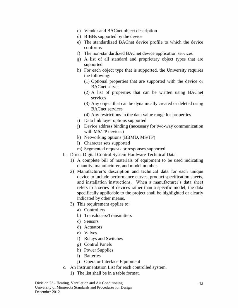
Division 23 - Heating, Ventilation and Air Conditioning
University of Minnesota Standards and Procedures for Design
December 2012
42
c) Vendor and BACnet object description
d) BIBBs supported by the device
e) The standardized BACnet device profile to which the device
conforms
f) The non-standardized BACnet device application services
g) A list of all standard and proprietary object types that are
supported
h) For each object type that is supported, the University requires
the following:
(1) Optional properties that are supported with the device or
BACnet server
(2) A list of properties that can be written using BACnet
services
(3) Any object that can be dynamically created or deleted using
BACnet services
(4) Any restrictions in the data value range for properties
i) Data link layer options supported
j) Device address binding (necessary for two-way communication
with MS/TP devices)
k) Networking options (BBMD, MS/TP)
l) Character sets supported
m) Segmented requests or responses supported
b. Direct Digital Control System Hardware Technical Data.
1) A complete bill of materials of equipment to be used indicating
quantity, manufacturer, and model number.
2) Manufacturer’s description and technical data for each unique
device to include performance curves, product specification sheets,
and installation instructions. When a manufacturer’s data sheet
refers to a series of devices rather than a specific model, the data
specifically applicable to the project shall be highlighted or clearly
indicated by other means.
3) This requirement applies to:
a) Controllers
b) Transducers/Transmitters
c) Sensors
d) Actuators
e) Valves
f) Relays and Switches
g) Control Panels
h) Power Supplies
i) Batteries
j) Operator Interface Equipment
c. An Instrumentation List for each controlled system.
1) The list shall be in a table format.

Division 23 - Heating, Ventilation and Air Conditioning
University of Minnesota Standards and Procedures for Design
December 2012
43
2) Include name, type of device, manufacturer, model number, and
product data sheet number.
d. Binding Map
1) A list of the device-to-device (peer-to-peer) data flow. This shall
not include the flow of data from devices to the OWS.
2) Include:
a) Description of the variable.
b) Sending device.
c) Receiving device.
G. Submittals During Construction
1. Training Plan
a. Submit the following six weeks in advance of the training:
1) Outline of the training with time allocations per topic.
2) Training presentation material (slides, word documents, etc.).
3) Copy of training reference material (product manuals to be used,
etc.).
4) Instructor’s name and resume with an emphasis on experience in
presenting training programs.
2. Startup Testing Plan
a. Submit a start up testing plan for each unique system at least two
weeks prior to equipment startup.
b. The purpose of a startup test is to demonstrate the completeness of the
system and the performance of the components.
c. For each task on the startup test checklist, the plan shall require the
technician to enter his or her initials and the date the test was
completed along with any recorded data such as voltages, offsets, or
tuning parameters. Any deviations from the submitted installation
plan shall also be recorded.
d. Required elements of the startup testing include:
1) Measurement of voltage sources, primary and secondary.
2) Verification of proper controller power wiring.
3) Verification of component inventory when compared to the
submittals.
4) Verification of labeling on components and wiring.
5) Verification of connection integrity and quality (loose strands and
tight connections).
6) Verification of bus topology, grounding of shields and installation
of termination devices.
7) Verification of point checkout.
a) All I/O device wiring is landed per the submittals and functions
per the sequence of control.
b) Analog sensors are properly scaled and a value is reported.
c) Binary sensors have the correct normal position and the state is
correctly reported.
Division 23 - Heating, Ventilation and Air Conditioning
University of Minnesota Standards and Procedures for Design
December 2012
44
d) Devices controlled by analog outputs have the correct normal
position and move full stroke when so commanded.
e) Devices controlled by binary outputs have the correct normal
state and respond appropriately to energize/de-energize
commands.
8) Documentation of analog sensor calibration (measured value,
reported value and calculated offset).
3. Startup Testing Report.
a. Startup testing reports shall be submitted on a per system basis.
b. Startup testing reports shall be the documented results of the executed
startup testing plans.
4. Graphic Pages: Submit a sample graphic page for each type of page
described in the specification section on graphic pages.
H. Submittals After Construction
1. The following is a list of post construction submittals that shall be updated
to reflect any changes during construction and re-submitted as “As-Built”.
As-Built drawings will each be stamped “As-Built” and have the as-built
date on them. The As-Built drawings will contain at a minimum:
a. System architecture drawing.
b. Detailed drawings for each piece of controlled and monitored
equipment
1) Layout drawing for each control panel.
2) Wiring Design Diagram for each control panel.
a) The control voltage wiring diagram shall clearly designate
devices powered by each control transformer. The diagram
shall clearly show the consistent grounding of the appropriate
power connection. All wire identification numbers shall be
annotated on the diagram.
b) If shielded communication wiring is used, the grounding of the
shield shall be shown.
c) The terminal strip wiring diagram shall identify all connections
on both sides of the terminal strip. Wiring label numbers for
all wiring leaving the control panel shall be annotated on the
diagram.
d) Where pneumatic devices are monitored or controlled by the
DDC systems, the control panel wiring diagrams shall include
pneumatic piping diagrams for all components.
3) Wiring diagram for individual components.
4) Point lists
5) Room Schedules
6) Sequence of operation
7) Hardware with part number information
8) System flow diagram for each controlled system.
Division 23 - Heating, Ventilation and Air Conditioning
University of Minnesota Standards and Procedures for Design
December 2012
45
c. Detailed routing of all communication trunk wires (building-to-
building and within building), locations of all network and integration
devices, front-end workstations, UPS and campus network/LAN
connections.
d. Binding map.
2. Operation and Maintenance Manuals
a. The controls contractor shall provide one electronic (PDF) copy and
three (3) bound copies of Operation and Maintenance Manuals.
b. Deliver manuals to the University project manager.
c. Manuals shall be bound in heavy-duty, vinyl-covered, three-post,
loose-leaf binders, permanently labeled on front and spine of each
binder.
d. Arrange the manuals according to specification section numbers used
in the Project Manual; include a table of contents that identifies the
responsible installing contractor, contact person, and telephone
number with area code and thumb tab index sheets.
e. Provide pocket folders for folded sheet information.
f. Maintenance and Operating Manual shall include the following type of
information:
1) One copy of the executed Certificate(s) of Substantial Completion.
This document will be used to communicate to all necessary
University personnel the starting date of the one-year Warranty
period.
2) Signed record copy of bonds, guarantees, and warranties required
by the Contract Documents.
3) Manufacturer’s required preventative maintenance inspections,
testing, service, lubrication, maintenance instructions, and
schedules.
4) Parts lists and local service organization.
5) As-built wiring and piping diagrams.
6) System architecture diagram for components within the building
annotated with specific location information.
7) As-built drawing for each control panel.
8) As-built wiring design diagram for each control panel.
9) As-built wiring design diagram for all components.
10) Installation design details for each I/O device.
11) As-built system flow diagram for each system.
12) Sequence of control for each system.
13) Room schedules.
14) Binding map for the building.
15) Product data sheet for each component.
16) Installation data sheet for each component.
17) Other information required by the Specifications.
g. The Contractor shall instruct University personnel in the use of
Maintenance and Operating Manuals.

Division 23 - Heating, Ventilation and Air Conditioning
University of Minnesota Standards and Procedures for Design
December 2012
46
3. Software
a. Submit a copy of all software installed on the servers and
workstations.
b. Submit all licensing information for all software installed on the
servers and workstations.
c. Submit two copies of all software used to execute the project even if
the software was not installed on the servers and workstations. This
includes all programs used to configure, program, and troubleshoot
both unit-level and system-level controllers. If the controllers require
proprietary cabling to use the software this cabling must also be
provided.
d. Submit all licensing information for all of the software used to execute
the project.
e. All software revisions shall be as installed at the time of the system
acceptance.
4. Firmware Files
a. Submit a copy of all firmware files that were downloaded to or pre-
installed on any devices installed as part of this project.
b. This does not apply to firmware that is permanently burned on a chip
at the factory and can only be replaced by replacing the chip.
c. Submit a copy of all application files that were created during the
execution of the project.
d. Submit a copy of all graphic page files created during the execution of
the project.
e. Submit a copy of all secondary graphic files such as bitmaps, jpegs,
etc. that were used in the creation of the graphic pages.
I. Project Closeout Submittals:
1. The controls contractor shall advise the Owner throughout the duration of
construction as to the status of the contract closeout submittals including,
but not limited to, the ongoing development of the maintenance and
operations manuals and record documents.
2. The Contractor shall assemble and submit as one package the following
before making application for final payment.
a. Consent of Surety.
b. Documentation that Contractor returned University keys.
c. Documentation that Contractor returned signs reading, “Construction
Staging Area, Vehicle Permit Required, Violators Will be Tagged and
Towed.”
d. Documentation that the Punch list is complete.
e. Executed Certificate of Occupancy (if required).
f. Executed TGB Total Payment Affidavit (if required).
g. Executed TGB Verification of Completed Work Affidavit (if
required).
h. Executed Prevailing Wage Payment Affidavit (if required).

Division 23 - Heating, Ventilation and Air Conditioning
University of Minnesota Standards and Procedures for Design
December 2012
47
i. Evidence of Completed Operations Liability insurance coverage
during the one-year correction period (if required).
j. Waste manifests, TCLP (Toxicity Characteristic Leachate Procedure),
and OSHA monitoring results for asbestos or lead, as required by the
Contract Documents (if required).
1.10 Project Record Documents
A. General Requirements:
1. The Contractor shall maintain a set of Contract Documents at the site, on
which variations shall be accurately marked with red erasable pencil on a
daily basis. All changes, whether resulting from change orders, Architect’s
supplementary instructions, Contractor change directives, or other job
noted changes, shall be recorded. The controls contractor shall
periodically verify that this is being done satisfactorily.
B. Contract Drawings
1. Maintain a clean, undamaged set of blue or black line prints of Contract
Drawings to use as the Project record documents.
2. Mark the drawing sets to show the actual installation where the installation
varies substantially from the work as originally shown.
3. Give particular attention to recording concealed elements that will be
difficult to measure and record at a later date. Also record new
information that is important to the Owner but is not shown on Contract
Drawings.
4. Note the related change order number where applicable.
5. Organize the record drawing sheets into manageable sets. Bind sets with
durable-paper cover sheets; print the University Project Number and
Name, and drawing numbers and titles on the cover sheet.
C. Record Project Manual
1. Maintain a clean, undamaged, complete set of the Project Manual to use as
the Project record documents.
2. Include one copy of the addenda and other written documents issued
during the construction period (Change Orders, RFIs, PRs, etc.) with the
record Project Manual.
3. Contractor shall submit the Project record documents to the University for
final inspection and comment at the completion of the job.
4. The final payment will not be made to the Contractor until the record
documents and the Maintenance and Operating Manuals are received and
approved in writing by the University.
5. Two months before expiration of the one-year correction period the
controls contractor shall conduct a walk through and provide a written
summary of findings and recommendations.
6. Submit electronic versions of all CAD drawings, points lists, and
operating sequences. The electronic copies shall be stored on CDs and
shall be saved in an editable format. Acceptable formats include
Division 23 - Heating, Ventilation and Air Conditioning
University of Minnesota Standards and Procedures for Design
December 2012
48
Microsoft Office program formats (i.e. Word, Excel, Access, etc.), Visio,
and AutoCAD. Other formats must be approved by the University at time
of project award.
1.11 Warranty
A. Warrant all work as follows:
1. The warranty period for labor and material for the control system,
including all subcontractor work, shall be 12 months after acceptance by
Owner. The Owner’s written acceptance will be given after verification
testing demonstrates that the equipment is operating in accord with the
contract documents. Minor deficiencies identified during testing that do
not affect the functional performance of the equipment will not be used to
deny acceptance for the purposes of determining the start of the warranty
period.
2. During the warranty period, the Contractor shall respond to the Owner’s
request for warranty service within 24 hours during normal business
hours.
3. For systems designated at critical, the Contractor shall respond to warranty
service requests within 4 hours.
4. The Contractor shall correct all warranty repairs at no cost to the Owner.
5. The Contractor shall make all reasonable efforts to minimize the Owner’s
business disruption and loss associated with warranty repairs. This
includes expedited shipping of materials, overtime work, night/weekend
work, etc.
6. Software upgrades and service patches shall be made available and
installed by the Contractor at no cost to the University during the warranty
period.
7. The Contractor shall maintain a copy of the project database through the
warranty period.
1.12 Ownership Of Proprietary Material

Division 23 - Heating, Ventilation and Air Conditioning
University of Minnesota Standards and Procedures for Design
December 2012
49
A. The Owner shall retain all rights to software for this project.
B. The Owner shall sign a copy of the manufacturer’s standard software and
firmware licensing agreement as a condition of this contract. Such license
shall grant use of all programs and application software to the Owner as
defined by the manufacturer’s license agreement, but shall protect the
manufacturer’s rights to disclosure of Trade Secrets contained within such
software.
C. The licensing agreement shall not preclude the use of the software by
individuals under contract to the owner for commissioning, servicing, or
altering the system in the future. Use of the software by individuals under
contract to the owner shall be restricted to use on the owner’s computers and
only for the purpose of commissioning, servicing, or altering the installed
system.
D. All project developed software, files and documentation shall become the
property of the Owner. These include but are not limited to:
1. Server and Workstation software
2. Application Programming Tools
3. Configuration Tools
4. Addressing Tools
5. Application Files
6. Configuration Files
7. Graphic Files
8. Report Files
9. Graphic Symbol Libraries
10. All Documentation.
1.13 Permits And Inspections
A. In accordance with Minnesota statute, the University of Minnesota enforces
the Minnesota State Building Code and other applicable codes and regulations
in University owned facilities. The University carries out this responsibility
through a University Building Official appointed by the Regents of the
University of Minnesota.
B. A building permit is required for all new construction, alterations, demolition,
remodeling, additions, electrical work, wiring, mechanical, plumbing work,
and temporary work that is conducted on University of Minnesota property.
The controls contractor shall obtain and pay for all permits and inspections
required for the electrical and mechanical work, arrange for inspections to be
performed, and furnish a certificate of final inspection and approval by
enforcement authorities. Contact University Code Office at 612.625.3318.
C. University Building, Electrical, Mechanical, Plumbing, or Fire Inspectors
shall inspect construction work conducted on University of Minnesota
property. Contractor shall request an inspection from the University Building

Division 23 - Heating, Ventilation and Air Conditioning
University of Minnesota Standards and Procedures for Design
December 2012
50
Code Division, 270 Donhowe Building, 319 - 15th Ave. SE, Minneapolis, MN
55455, (612) 625-3318, in accordance with current code office requirements.
D. As provided for in state law, the Contractor may be required to uncover work
that was covered prior to being inspected.
E. The controls contractor is to retain on the job site a signed copy of the
building permit, a copy of the inspection sign off card, requests for
mechanical/electrical inspections, and the University Building Code signed
and stamped approved plans and specifications.
F. When required, the Contractor shall obtain permits other than those issued by
the University Building Official, which include, but are not limited to, high-
pressure steam, elevators, and city and/or county utilities.
1.14 Hazardous Waste Management
A. The University will identify areas in the facility where asbestos or other
hazardous materials are known to exist.
B. Controls contractor shall identify all locations where the proposed
construction may disturb hazardous material in before performing any work
and notify the Owner. Owner shall coordinate all work with the University of
Minnesota hazardous abatement department to remove the asbestos material
as deemed necessary for the safety and well being of building occupants and
construction workers. All costs related to the removal of the hazardous
material shall be the responsibility of the University.
C. The Contractor or any of the subcontractors shall not remove asbestos
containing materials of any kind. Any trades working around any asbestos
containing materials shall take extra caution not to disturb those materials. If
this does not appear to be possible, the materials shall be requested to be
removed. Such requests shall be made to the Owner in a timely fashion so as
not to delay the project.
1.15 Solid Waste Management Plan
A. Provide for the management of construction and demolition waste through
reuse, recycling and reduction methods. Typical designated waste streams are:
land clearing debris, concrete and masonry, metals, dimensional wood &
lumber, wooden pallets, gypsum wallboard, paper and cardboard. Depending
on the project, other large volume wastes may be included (e.g., bricks,
asphalt, carpeting).
1. A specified percentage of the waste should be specially collected,
segregated and sent for recycling or reuse. Documented waste reduction
strategies will be credited against the goal.
2. Specification will include standard instructions for handling designated
wastes, stressing the need for not contaminating the recyclable wastes.
3. The Contractor is encouraged to work with the University’s Waste
Management Division to evaluate recycling options. The Waste
Division 23 - Heating, Ventilation and Air Conditioning
University of Minnesota Standards and Procedures for Design
December 2012
51
Management Division will also provide no cost service for recycling
properly segregated and uncontaminated cardboard and scrap metals.
4. Reduction: Reduction includes eliminating excess material use or waste.
Examples of reduction include ordering materials to fit the module of the
design, such as eliminating cut-off waste from lumber, drywall or
carpeting; working with suppliers to eliminate or reduce packaging.
5. Reuse: Reuse includes salvaging components from remodeling or
demolition projects for resale or transfer to salvage businesses, non-
profits, material exchange networks, or for use in new construction at the
same site or elsewhere. Reusable items include plumbing and mechanical
equipment, doors, windows, fixtures, trim, etc. Other reuse strategies
include returning unused products or shipping containers (pallets) to
vendors.
6. Recycling: Recycling includes the recovery of materials that have existing
and stable markets. These materials can be used as raw materials for the
manufacturing of new products. Examples include cardboard, metals and
concrete.
B. Submittals:
1. Contractor shall submit the Construction Solid Waste Management Plan to
Project Manager 10 days prior to start of construction. The plan should
include the following elements:
a. Whether construction waste will be recycled or reused by source
separation, time-based separation, or commingled for delivery to an
off-site separation facility.
b. The types of materials to be targeted for recycling and reuse, the
projected volumes and fate of the materials. Identify materials that are
recyclable or otherwise recoverable that must be disposed of in a
landfill.
c. The diversion goal indicates the percentage of waste to be diverted
from land filling or incineration.
d. The facilities to be used, both landfills and recycling facilities,
indicating which of the targeted wastes are to be received, projected
volumes, and documentation of their permit status.
e. Maintenance of a Construction Waste Log (dates, facility, transporter,
weights) and a file of waste receipts for all wastes shipped off-site.
C. Implementation:
1. Contractor shall conduct a Pre-Construction Waste Management
Conference to discuss the Plan requirements, schedules and procedures
with Contractor personnel associated with waste management, the
Architect, suppliers (where appropriate), and Project Manager.
2. Contractor shall designate the on-site party responsible for implementing
the plan and instructing workers, distributing plan to site foremen and each
subcontractor, including the plan in worker orientation and safety
meetings, and providing site instruction on separation, handling, and
recovery methods.

Division 23 - Heating, Ventilation and Air Conditioning
University of Minnesota Standards and Procedures for Design
December 2012
52
PART 2. Products
2.1 Manufacturers
A. Approved Manufacturers
1. Johnson Controls
2. Siemens
3. University Approved Alternate
B. Acceptable Installation Contractors
1. Branch offices and independent representatives for the above
manufacturers must have a full staff of project managers, project
engineers, system application engineers, application engineers and
technicians. Branch offices and independent representatives must have a
separate fully staffed service department to be an acceptable bidder.
2. Approved Installation Contractors
a. Johnson Controls Branch Office – Minneapolis
b. Siemens Building Technologies Branch Office – Minneapolis
c. Trane Branch Office – Minneapolis
d. University Approved Alternate
3. Installation contractors not currently on the approved list may be
considered if they meet the requirements of this specification. Financial
stability and prior experience on University (or similar) projects will be
considered by the Owner when selecting an installation contractor.
2.2 System Architecture
A. The DDC system architecture shall consist of two layers, the TCP/IP layer and
the field bus layer.
B. The TCP/IP layer connects all of the buildings on a single dedicated and
isolated network. Fixed IP addresses for connections to the University private
DDC network shall be used for each device.
C. BACnet Building Controllers (B-BC) shall be used to connect each field bus
to the TCP/IP layer.
2.3 Networking
A. IP Network: All devices that connect to the WAN shall be capable of
operating at 100 megabits per second.
B. IP-to-Field Bus Routing Devices
1. BACnet Building Controller shall be used to provide this functionality.
2. These devices shall be configurable locally with RS232 or IP crossover
cable and configurable via the IP network.
3. The routing configuration shall be such that only data packets from the
field bus devices that need to travel over the IP level of the architecture are
forwarded.

Division 23 - Heating, Ventilation and Air Conditioning
University of Minnesota Standards and Procedures for Design
December 2012
53
C. Field Bus
1. The wiring of components shall use a bus or daisy chain concept with no
tees, stubs, or free topology.
D. Repeaters
1. Where repeaters are required to connect two segments, repeaters shall be
installed in an enclosure mounted in an accessible area.
2.4 Building Level Controllers (B-BC)
A. Building level DDC controllers shall be microprocessor-based, multi-tasking,
multi-user, real-time digital control processors fully capable of being
integrated with the selected vendor’s master work station, or any third party
BACnet workstation.
B. Building level DDC controllers shall utilize BACnet open standard
communication protocol. All building level controllers shall communicate
using BACnet/IP.
C. A BACnet Building Controller (B-BC) as defined by ASHRAE Annex L is a
general purpose, field programmable device capable of carrying out a variety
of building automation and control tasks. It enables the specification of the
following:
1. Data Sharing
a. Ability to provide the values of any of its BACnet objects
b. Ability to retrieve the values of BACnet objects from other devices
c. Ability to allow modifications such as scheduling and present value of
some or all of its BACnet objects by another device as shown in U of
M required object table (see Appendix A).
2. Alarm and Event Management
a. Generation of alarms / events notifications and the ability to direct
them to recipients using the BACnet intrinsic alarming method
b. Maintain a list of unacknowledged alarms / events retrievable using
standard BACnet Services
c. Maintain a list of alarms / events retrievable using standard BACnet
Services
d. Notifying other recipients that the acknowledgment has been received
e. Adjustment of alarm / event parameters
3. Scheduling
a. Ability to schedule output actions, both in the local device and in other
devices, both binary and analog, based on date and time
4. Trending
a. Collection and delivery of (time, value) pairs
5. Device and Network Management
a. Ability to respond to information about its status
b. Ability to respond to requests for information about any of its objects
c. Ability to respond to communication control messages

Division 23 - Heating, Ventilation and Air Conditioning
University of Minnesota Standards and Procedures for Design
December 2012
54
d. Ability to synchronize its internal clock upon request. (not required by
U of M)
e. Ability to perform re-initialize upon request (not required by U of M)
f. Ability to upload its configuration and allow it to be subsequently
restored
g. Ability to command half routers to establish and terminate connections
(not required by U of M)
D. If Building Controllers have embedded I/O, all of the requirements for I/O
that are described under Unit Level Controllers shall apply.
E. The temperature controls contractor's B-BC device(s) shall support all
ANSI/ASHRAE 135-2004 standard object required and optional properties as
listed in Appendix A. BACnet intrinsic alarming is required. All objects
and object properties shall be supported so that alarms are sent from the
temperature controls contractor's BACnet device without having to be
solicited from the University BACnet Operators Workstation (BOWS) or U of
M Master History PC.
F. DDC panels and devices must utilize ANSI/ASHRAE 135-2004 BACnet
Communications Protocol on a single building level network. BACnet
communications must not cause derogated communications on the sites
existing temperature control network. Derogation includes router, switch, or
hub lockups, BACnet building controller lockups, excessive site network
slowdowns, unnecessary and repeated ‘who is’ messages. Refer to ASHRAE
BACnet standard for definition of unnecessary Who-is messages.
G. U of M BACnet Required Protocol Services supported:
1. Acknowledge Alarm
2. Confirmed Event Notify
3. Get Alarm Summary
4. Get Enrollment Sum
5. Add List Element (for the purpose of allowing the addition of a recipient
to the BB-C)
6. Remove List Element (for the purpose of allowing the deletion of a
recipient to the BB-C)
7. Read Property
8. Read Property Multiple
9. Write Property
10. Write Property Multiple
11. Confirm Private Xfer
12. I AM
13. I Have
14. Unconfirmed COV Notify
15. Unconfirmed Event Notify
16. Time Synchronization
17. Who Has

Division 23 - Heating, Ventilation and Air Conditioning
University of Minnesota Standards and Procedures for Design
December 2012
55
18. Who Is
19. UTC Time Sync
20. Get Event Info

Division 23 - Heating, Ventilation and Air Conditioning
University of Minnesota Standards and Procedures for Design
December 2012
56
H. All building controllers must be capable of having their databases uploaded,
downloaded and viewed from the vendor’s master workstation.
I. All building level controllers shall have a local port that can connect to a
laptop PC or other hand-held tool for local service work, troubleshooting, etc.
Each controller shall include the capability to store, retrieve and print alarm
summaries, trends and other critical point summaries or reports.
J. Memory: Each DDC controller shall have sufficient memory to support its
own operating system and databases and continuous trending on all analog
points for that controller (AV, AI, AO) based on 300 sample intervals.
K. Integrated On-line Diagnostics: Each DDC controller shall continuously
perform self-diagnostics and communication diagnosis of all associated unit
level equipment. The DDC controller shall provide both local and remote
annunciation of any detected component failures, or repeated failure to
establish communication. Indication of the diagnostic results shall be
provided at each DDC controller and shall not require the connection of an
auxiliary I/O device.
L. Power Fail Restart: In the event of the loss of normal power, there shall be an
orderly shutdown of all DDC controllers to prevent the loss of database or
operating system software. Non-volatile memory shall be incorporated for all
critical controller configuration data, and battery back up shall be provided to
support the real-time clock and all volatile memory for a minimum of seventy-
two (72) hours. Upon restoration of normal power, the DDC controller shall
automatically resume full operation without manual intervention. Should a
DDC controller memory be lost for any reason, the user shall have the
capability of reloading the DDC controller via the local area network or via
the local interface port.
M. System architectural design shall eliminate dependence upon any single
device, front-end or higher level of controller for alarm reporting and control
execution. Each DDC controller shall operate independently by performing
its own specified control, alarm management, operator I/O, and historical data
collection. The failure of any single component or network connection shall
not interrupt the execution of control strategies at other operational devices.
N. Building level DDC controllers shall be able to access any data from, or send
control commands and alarm reports directly to any other building level
controller or combination of controllers on the IP network without dependence
upon a central processing device. Building level DDC controllers shall also be
able to send alarm reports to multiple operator workstations without
dependence upon a central processing device.
O. All Ethernet network communications will use 100 MPS communication
rates.
2.5 Unit Level Controllers
A. Each Unit Level DDC controller shall consist of modular hardware with plug-
in enclosed processors, communication controllers, power supplies, input and

Division 23 - Heating, Ventilation and Air Conditioning
University of Minnesota Standards and Procedures for Design
December 2012
57
output (DI, DO, AI, AO) capabilities. A sufficient number of controllers shall
be supplied to fully meet the requirements of this specification, the project
drawings, and the point lists.
B. Unit level DDC controllers shall utilize BACnet/MSTP or LON open standard
communication protocol.
C. All unit level controllers, including VAV controllers, must be able to have
their databases uploaded, downloaded and viewed from the vendor’s master
workstation.
D. Power Fail Restart: In the event of the loss of normal power, there shall be an
orderly shutdown of all DDC controllers to prevent the loss of database or
operating system software. Non-volatile memory shall be incorporated for all
critical controller configuration data, and battery back up shall be provided to
support the real-time clock and all volatile memory for a minimum of seventy-
two (72) hours. Upon restoration of normal power, the DDC controller shall
automatically resume full operation without manual intervention. Should a
DDC controller memory be lost for any reason, the user shall have the
capability of reloading the DDC controller via the local area network or via
the local interface port.
E. Each controller will be programmed such that each controlled device will
have a default value in which to be commanded to in the event of a control
sensor failure. The acceptable default values are, last command, full open, or
full closed.
F. Controller I/O Requirements
1. Analog Input Circuits
a. The resolution of the A/D chip shall not be greater than 0.01 Volts per
increment. For an A/D converter that has a measurement range of 0 to
10 VDC and is 10 bit, the resolution is 10/1024 or 0.00976 Volts per
increment.
b. For non-flow sensors, the control logic shall support a calibration
offset such that the raw measured value is added to the (+/-) offset to
create a calibration value to be used by the control logic and reported
to the Operator Workstation (OWS).
c. For flow sensors, the control logic shall provide support for the use of
an adjustable gain and an adjustable offset such that a two point
calibration concept can be executed (both a low range value and a high
range value are adjusted to match values determined by a calibration
instrument).
d. For non-linear sensors such as thermistors and flow sensors the
controller shall provide software support for the linearization of the
input signal.
2. Binary Input Circuits
a. Dry contact sensors shall wire to the controller with two wires.
b. An external power supply in the sensor circuit shall not be required.

Division 23 - Heating, Ventilation and Air Conditioning
University of Minnesota Standards and Procedures for Design
December 2012
58
3. Pulse Input Circuits
a. Pulse input sensors shall wire to the controller with two wires.
b. An external power supply in the sensor circuit shall not be required.
c. The pulse input circuit shall be able to process up to 20 pulses per
second.
4. True Analog Output Circuits
a. The logical commands shall be processed by a digital to analog (D/A)
converter chip. The 0% to 100% control signal shall be scalable to the
full output range which shall be either 0 to 10 VDC, 4 to 20 milliamps
or 0 to 20 milliamps or to ranges within the full output range.
b. The resolution of the D/A chip shall not be less than 0.04 Volts per
increment or 0.08 milliamps per increment.
5. Binary Output Circuits
a. Single pole, single throw or single pole, double throw relays.
b. Voltage sourcing or externally powered triacs with support for up to
30 VAC and 0.5 amps at 24 VAC.
6. Program Execution
a. Process control loops shall operate in parallel and not in sequence
unless specifically required to operate in sequence by the sequence of
control.
b. The sample rate for a process control loop shall be adjustable and shall
support a maximum sample rate of 1 second.
c. The sample rate for process variables shall be adjustable and shall
support a maximum sample rate of 1 second.
d. The sample rate for algorithm updates shall be adjustable and shall
support a maximum sample rate of 1 second.
e. The application shall have the ability to determine if a power cycle to
the controller has occurred and the application programmer shall be
able to use the indication of a power cycle to modify the sequence of
controller immediately following a power cycle.
7. Local Interface: The controller shall support the connection of a portable
interface device such as a laptop computer or vendor specific hand-held
device. Via this local interface, an operator shall be able to:
a. Adjust application parameters.
b. Execute manual control of input and output points.
c. View dynamic data.
G. Unit level controllers shall not be dependent upon any other controller (unit or
building level) to maintain safe operation of the controlled equipment.
H. All unit level controllers and/or enclosures shall be clearly labeled with their
Node address. Tag all wiring on the DDC side of the interface panel
identifying the associated point.
I. PROHIBITED: Using a single unit level controller (or building level
controller that is serving as a unit level controller) to control more than one
major mechanical system without the express permission of the Owner. The

Division 23 - Heating, Ventilation and Air Conditioning
University of Minnesota Standards and Procedures for Design
December 2012
59
intent is to minimize disruptions to multiple systems if a single controller fails
or must be serviced/programmed. A voluntary deduct may be provided with
the proposal stating which systems will be controlled by a common controller
and the associated price reduction. Major mechanical system is defined as:
1. Air handling units
2. Heating systems (multiple pumps and heat exchangers that are part of the
same overall heating loop can be combined).
3. Cooling systems (multiple pumps, chillers, towers, etc. associated with the
same cooling loop can be combined).
4. Building exhaust systems.
5. Other building systems where a failure of multiple devices will cause
significant disruption to building operations.
J. PROHIBITED: Transmitting process variable data via the IP network or field
bus for use in PID control loops. Data transmitted from point expansion
modules to unit controllers via a dedicated point expansion communication
bus is allowed.
K. PROHIBITED: Splitting mechanical systems between more than one Unit
Level controller without prior approval from Owner.
2.6 Operator Workstation (OWS)
A. The Operator Interface Workstations will comprise a Personal Computer (PC)
together with operator terminals. The PC will be a fully integrated node on the
management level network and shall provide the operator with a graphical
interface into the entire network. The monitoring and control functions of the
BMCS shall be totally independent of the PC such that if the PC is not
operational there shall be no impact on the building control systems except for
the reduced operator interface capability at that location.
B. Provide OWS meeting, at minimum, the following requirements:
1. Intel motherboard with single Intel Core 2 Duo processor with a
minimum speed of 3.0 GHz and 4 MB L2 Cache.
2. 2 Gigabyte of memory.
3. One 160 Gigabyte SATA hard drive.
4. Tower or desktop style case.
5. 4 USB ports.
6. 48x32xCDRW and 16xDVD+/-RW.
7. Auto sensing full duplex 10/100/1000 Ethernet network interface card
(NIC).
8. USB style connectors for keyboard and mouse.
9. 256 Megabyte video RAM.
10. All necessary mounting hardware and cables for all components.
11. Integral power supplies which shall be suitably rated for the service.
12. Real time software or hardware clock.
13. 1.44 Floppy disk drive

Division 23 - Heating, Ventilation and Air Conditioning
University of Minnesota Standards and Procedures for Design
December 2012
60
C. Provide a Video Display Unit (VDU) meeting, at minimum, the following
requirements:
1. Flat panel LCD display with screen diagonal measurement of no less than
19 inches.
2. Resolution of .28 pitch, 1280 by 1024 pixels with 85Hz minimum refresh
rate.
3. Capable of displaying both schematic and alphanumeric data at the same
time.
4. 16 million discrete colors.
5. Manufactured by NEC, Viewsonic, Sony, Samsung, or approved equal.
2.7 DDC System Software
A. BACnet Operator Workstations
1. Hardware Communication Function
a. The OWS shall extract data from the hardware environment and move
the data to the data server and/or present the data to the presentation
system.
b. The OWS shall extract data from the data server and present the data
to the data presentation system.
c. The OWS shall track operator actions at the presentation system and
write a record of activities to the data server.
2. BACnet Compliance
a. The OWS shall be able to initiate a “Who Is” request to the network.
b. The OWS shall respond to a “Who Is” request from another BACnet
device with an “I Am” response.
c. The OWS shall be able to read binary and analog data from BACnet
devices that support the reading of data.
d. The OWS shall be able to write binary and analog data to BACnet
devices that support the writing of data from a BACnet OWS.
e. The OWS shall be able to receive alarm messages from BACnet
devices that export alarm messages.
f. The OWS shall be able to acknowledge alarms from BACnet devices.
g. The OWS shall be able to edit time schedule parameters in BACnet
devices that support the editing of time schedule parameters from a
BACnet OWS.
h. The OWS shall be able to retrieve a collection of trend samples from a
BACnet device that stores the data and permits the export of that data
to a BACnet OWS.
i. The OWS shall be able to initiate time synchronization commands to
all BACnet devices that support the receipt of time synchronization
commands from a BACnet OWS.
3. Data Presentation: Data shall be presented in the following formats.
a. Points lists with dynamic presentation of data. The operator shall be
able to create custom point lists with data that originates from multiple

Division 23 - Heating, Ventilation and Air Conditioning
University of Minnesota Standards and Procedures for Design
December 2012
61
devices. A point may be dynamic data from a controller or a
configuration parameter to be written to a controller by the operator.
b. Graphic pages with dynamic presentation of data on a visual diagram
that represents a building, a floor plan, a cross section of a mechanical
system or a table of data.
c. Graphical presentation of historical trend log data plotted against time.
d. Graphical presentation of real time trend data plotted against time.
e. Alarm Presentation
1) Unless restricted by a reduction in viewing authority, an operator
shall be able to view alarms for all systems in a single alarm list.
2) Custom alarm views configured for select categories of alarms
shall present only the alarms specified.
3) Alarm messages shall include identifying information and the
signal value or state at the time of the alarm.
f. Event Presentation
1) Unless restricted by a reduction in viewing authority, an operator
shall be able to view an event log that chronologically captures all
activity created by the system and operator actions.
2) Custom event views for select categories of events shall present
only the events specified.
g. Time Schedules
1) Each time schedule shall have the ability to issue a minimum of 10
start and 10 stop commands for the week. The requirements for
start and stop commands may be different for each day of the
week.
2) Each time schedule shall also include a holiday component where a
holiday is identified by the date and duration (one day, two days,
etc.). The time schedule shall support a unique set of start and stop
commands for each holiday. The time schedule shall support a
minimum of 20 holidays per year. Holiday schedules shall take
precedence over standard schedules during the holiday period.
Holidays that are date specific shall roll over from year to year
without operator programming action.
3) There shall be a mechanism to link a master time schedule editor at
an OWS to multiple time schedules in various Building
Controllers. Once linked, whenever the master time schedule is
changed at an OWS, the new time schedule parameters shall be
downloaded to all of the linked time schedules. This concept shall
apply to both standard schedules and holiday schedules.
h. The system shall support a configuration that:
1) Causes the system to go into standby mode (user is logged out but
the current screen is still displayed) after a specific period of
inactivity.
2) Automatic system logout after a specific period of inactivity.
4. Data Source

Division 23 - Heating, Ventilation and Air Conditioning
University of Minnesota Standards and Procedures for Design
December 2012
62
a. An operator workstation shall present data from the entire hardware
environment.
b. The system architecture shall provide for a minimum of 25 concurrent
operator workstations per system.
5. Operator Access And Privileges
a. There shall be a minimum of four privilege levels.
1) System Administrator
a) No limitations
b) Only level that can assign or delete users and assign or modify
privileges.
2) Engineer
a) View data in any format.
b) Acknowledge alarms.
c) Inhibit alarms.
d) Exercise control actions.
e) Edit the presentation of data.
f) Modify the system.
3) Operator
a) View data in any format.
b) Acknowledge alarms.
c) Exercise control actions.
4) Viewer
a) View data in any format.
b. The level assigned to a specific user shall be the maximum level that
can be used any where in the system. The software shall provide the
capability to reduce a user’s level from his or her maximum level to a
lower level on a per building or system basis. This may be
accomplished on a per object basis within the database or by the
application of additional security levels beyond the basic four levels.
c. Signing on to the system shall require a user name and password.
When the password is typed in, it shall not be shown on the screen.
d. The software shall provide the capability to establish groups of users
with the same privileges. Once assigned to the group, the user shall
automatically have the maximum privileges and the selectively
reduced privileges assigned to the group.
e. The software shall provide the capability to set user profiles that
enable assigning a specific home graphic page, alarm view, and event
view.
6. Operator Actions
a. Given the appropriate authority, an operator from an operator
workstation shall be able to:
1) View all data that is presented in the forms described previously.
2) Acknowledge alarms.
3) Manually control both physical input and physical output points.
Division 23 - Heating, Ventilation and Air Conditioning
University of Minnesota Standards and Procedures for Design
December 2012
63
4) Edit both independent and master time schedules.
5) Initiate real time trend logging.
6) Manually initiate reports.
7) Initiate system backups for the database and trend log data.
8) Customize the layout of the operator workstation presentation
which shall then be the default for that user.
b. The operator shall be able to execute the above tasks on data from any
of the operator workstations.
c. The system shall support the use of Electronic Signature system wide
or on a per user basis.
d. All of the operator workstations shall be operable simultaneously.
7. Engineering Actions
a. The software shall, as a minimum, enable the following engineering
functions from each of the operator workstations:
1) Create graphic pages for the presentation of dynamic data on visual
images of buildings or equipment.
2) Create reports for the presentation of historical data in an
organized format.
3) Create time schedules.
4) Create trend logs in any of the field level devices and assign a
dynamic variable from a field bus device to be trended.
5) Setup long term storage of trend log data on the data server
computer and the automatic transfer of the trend log data to the
data storage tables in the long-term database.
6) Create alarm objects in any of the field level devices, assign an
alarm variable from a field bus device to initiate the alarm and set
up the alarm routing.
7) Configure and bring on-line a newly installed Building Controller
in support of an initial or incrementally added building control
system.
8) Configure and bring on-line a newly installed field level devices in
support of an initial or incrementally added building control
system.
9) Create and download applications for programmable devices.
10) Download firmware updates to field level devices.
11) Import all field level devices into the system so that all input
network variables, output network variables and adjustable
application parameters can be accessed from any of the operator
workstations.
12) Establish data flow from one field level device to a second field
level device.
13) Establish data flow from a field bus device under one IP
connection to a field bus device under a different IP connection.
14) Configure the system to create backups of the database and all
application and supporting databases on a scheduled basis.
Division 23 - Heating, Ventilation and Air Conditioning
University of Minnesota Standards and Procedures for Design
December 2012
64
15) Setup user groups and individual users and establish authority
levels for each group and individual user.
16) Any additional tasks defined later in this document or required to
deliver a fully functional system.
B. Graphic Page Creation And Editing
1. The Graphics Editor portion of the Engineering Software shall provide the
following minimum capabilities:
a. Create and save symbols.
b. Create and save pages.
c. Group and ungroup symbols.
d. Modify an existing symbol.
e. Modify an existing graphic page.
f. Rotate and mirror a symbol.
g. Place a symbol on a page.
h. Place analog dynamic data in decimal format on a page.
i. Place binary dynamic data using state descriptors on a page.
j. Create motion through the use off gif, jpeg, bmp or svg files
k. Place test mode indication on a page.
l. Place manual mode indication on a page.
m. Place links using a fixed symbol or flyover on a page.
1) Links to other graphics.
2) Links to web sites.
3) Links to notes.
4) Links to time schedules.
5) Links to trends.
n. Assign a background color.
o. Assign a foreground color.
p. Place alarm indicators on a page.
q. Change a symbol color as a function of an analog variable.
r. Change a symbol color as a function of a binary state.
s. Change symbols as a function of a binary state.
t. All symbols used by the contractor in the creation of graphic pages
shall be saved to a library file for use by the owner.
C. Event Logging
1. The system shall maintain a log of all operator activity, system messages,
alarms, and alarm acknowledgments.
2. Operator activity is defined as any action by an operator such as changing
the value of an application parameter, modifying a program,
acknowledging an alarm, logging on, logging off, etc. Any change in the
system caused by operator action shall be part of the log. The log shall
include the event, the time of the event, the part of the system affected,
and an identification of the operator and the OWS from which the change
was made.

Division 23 - Heating, Ventilation and Air Conditioning
University of Minnesota Standards and Procedures for Design
December 2012
65
3. When the event deals with a value change, both the original and new
values shall be part of the event record.
4. The Event Log shall be exportable to a report format that is printable.
5. The System Administrator shall be able to archive the event log.
6. The event data shall comply with 21 CFR Part 11 requirements for data
integrity.
7. The Event Log shall have a search function with assignable criteria to
identify subsets of the event log such as all points placed under manual
control, etc.
D. Alarm Generation And Processing
1. Alarm creation is a two part process. The creation of a binary alarm
indication is accomplished in a field level device where a binary state of
zero shall indicate a normal condition and a binary state of one shall
indicate an alarm condition. The binary alarm condition is read within a
B-AAC, or Building Controller. The B-AAC or Building Controller shall
assign a descriptive message, a category or priority number and a date and
time stamp to the alarm and forward the information to the OWS in
accordance with an alarm routing table.
2. Alarm parameters such as high limits, low limits, time to state, binary
alarm conditions are setup within the programming of the field level
devices. These parameters shall be viewable and editable in point lists and
on configuration graphic pages.
3. The alarm message shall be descriptive.
a. Building identification
b. System identification
c. Device identification
d. Date
e. Time to the second
f. Nature of the alarm
1) High value
2) Low value
3) Fail to start
g. Value or state at the time of the alarm.
4. When the operator acknowledges the alarm, there shall be an opportunity
to enter a message that becomes a permanent part of the alarm record
recorded in the event log.
5. The system shall support the association of graphic pages, trend charts,
reports and text documents with specific alarms.
a. The operator shall have the ability to configure the system to auto-
launch a specific graphic page when the alarm occurs.
b. The system shall support the assignment of wav files to alarm signals
on graphic pages.
c. The operator shall have the ability to launch a specific trend chart from
the alarm window when the alarm occurs.

Division 23 - Heating, Ventilation and Air Conditioning
University of Minnesota Standards and Procedures for Design
December 2012
66
d. The operator shall have the ability to launch a specific text document
when the alarm occurs.
e. An associated report shall automatically execute and write to the hard
disk on the OWS when the alarm occurs. Configurations options shall
include overwriting the previous report or creating a new file.
6. The system shall use selectable multiple colors on alarm messages for
each of the following conditions:
a. Alarm condition exists and has not been acknowledged
b. Alarm condition has returned to normal but was never acknowledged
c. Alarm condition exists and has been acknowledged
7. When an alarm condition no longer exists and has been acknowledged, it
shall no longer be displayed in the alarm viewer but it shall be
permanently recorded in the event list.
8. The Alarm Routing Table shall support the following:
a. Multiple workstations at any time.
b. Specific workstations at particular times (to include all of the time as
one choice).
c. Pagers
d. Email addresses via simple mail transfer protocol (SMTP; RFC 821)
e. Permanent comprehensive system wide alarm file
f. Specific alarm file based on a building or equipment identification
g. One or more alarm printers at any time
h. Specific alarm printers at specific times
i. Rerouting of alarms to a backup receiver when an acknowledgement
has not been entered into the system within a specified time.
9. The system shall have a default audible indicator generated by the
computer when an alarm is received.
10. Once an alarm is acknowledged at one OWS, it shall display as
acknowledged at all operator workstations.
11. An operator shall be able to select multiple alarms for single action
acknowledgement.
12. There shall be the ability to disable alarms.
13. The OWS alarm viewer shall be able to display the last 100 active alarms.
If there are more than 100 active alarms, as alarms are acknowledged and
removed from the viewer, older alarms shall be viewable to keep the
viewer showing the last 100 active alarms until there are less than 100
active alarms.
E. Trends
1. Real Time Trends:
a. At each OWS the operator shall be able to initiate a real time trending
instance of up to 10 variables simultaneously.
b. The polling interval setting shall be adjustable down to a rate of every
second.
Division 23 - Heating, Ventilation and Air Conditioning
University of Minnesota Standards and Procedures for Design
December 2012
67
c. The data for each instance shall be presented on a single graphical
display that automatically updates with each new data collection cycle.
d. The graphical presentation shall plot the variables on the Y axis and
time on the X axis.
e. A minimum of two Y axis scales shall be available.
f. The operator shall have the ability to set the range on each Y axis scale
or let the scales auto range to cover the range of the values being
trended.
g. Each element of data on the graphical display must be labeled by name
or by a unique color. If color is used, a color legend must be included
on the graph.
h. The operator shall be able to open up to five instances simultaneously
for a total of 100 points being trended at one time.
i. An operator shall be able to print an instance of real time data.
j. The system shall be capable of trending any variable in the system.
k. The operator shall be able to save pre-configured instances of real time
trending that can be initiated with simple point and click actions.
2. Historical Data Collection:
a. Historical trend data shall be collected by field level devices and
periodically uploaded to the data server.
b. The trend log objects in the field level devices shall have the capacity
to store 300 samples per variable. When the 301st sample is collected,
the 1st sample shall be discarded.
c. The field level devices shall be configured to request an upload of data
when the number of samples is not greater than 180. Uploads may be
configured to occur at a greater frequency.
d. Initiation of historical data collection shall be configurable.
1) By manual operator intervention in a point and click manner.
2) By a user adjustable time schedule or date.
3) Triggered by a binary status variable (when the fan status is on,
start the trend of the mixed air temperature).
4) The system shall be capable of trending any variable in the system.
e. The status and capacity of the trend logs in the field devices shall be
viewable from the operator workstation.
3. Historical Data Presentation:
a. An OWS shall have the capability to present the historical data for a
variable in a tabular presentation of the values along with the date and
time of the sample. The time period for the values to be presented
shall be user adjustable.
b. An OWS shall have the capability to present the historical data for a
variable in a graphical presentation of the values plotted against time
and date.
c. The graphical presentation capabilities for historical trends shall equal
those described above for real time trends.

Division 23 - Heating, Ventilation and Air Conditioning
University of Minnesota Standards and Procedures for Design
December 2012
68
d. The operator shall be able to save pre-configured instances of
historical trending that can be initiated with simple point and click
actions.
e. The operator shall be able to print the tabular presentations and
graphical presentations of historical trend data.
4. The data collection, storage, retrieval and presentation system shall
provide the features necessary for the owner to achieve certification under
21 CFR Part 11. The key issue is the integrity of the data, the ability to
verify that the data has not been modified after collection by the system.
F. Application Programming
1. The application programming tool may be based on Line Programming or
Graphical Programming concepts.
2. If the application programming is object based and graphical:
a. There shall be an off-line simulation capability.
b. There shall be the ability to view dynamic data displayed on the object
diagram in real time.
3. There shall be self checking for errors in programming to be used by the
programmer.
4. Key functions that must be supported are:
a. Timer functions to include Delay Off, Delay On and Sample Rate
Support
b. Interval timer
c. Math functions to include Addition, Subtraction, Multiplication,
Division, Exponentiation, Trigonometric Functions and Logarithmic
Functions (base 2 and base 10)
d. If-Then-Else Instructions (also referred to as switching logic)
e. Look up tables with a minimum of 100 entries, with and without
extrapolation
f. Bit Wise Logic
g. Sample and hold binary
h. Sample and hold analog
i. Latch on and latch off functions with resets
j. Input network variable definition
k. Output network variable definition
l. Sensor measurement definition
m. End device control definition
n. Logic functions to include And, Or, Not and Exclusive Or
o. Detection of a power cycle
p. Common function support (standard objects in graphical programs and
subroutines in line programs). As a minimum the common functions
shall include:
1) PID with analog output
2) PID with tri-state outputs
3) Enthalpy from temperature and relative humidity

Division 23 - Heating, Ventilation and Air Conditioning
University of Minnesota Standards and Procedures for Design
December 2012
69
4) Optimum start stop based on occupancy schedule, temperature, set
point and outside air temperature.
5) Polynomial equation
G. Report Creation
1. The operators shall be able to extract historical data from the data
collection files and present the data in a Microsoft Excel format. All of
the data in the log shall be exportable to include the date, time and values.
2. The number of trend logs that can be inserted into a single Excel
Workbook shall not be limited by the OWS software.
3. The operators shall be able to pre-configure reports for manual execution
or automated execution.
4. The OWS shall be able to auto execute any report based on:
a. A time schedule
b. An alarm trigger
c. The status of a binary point (state=1, execute the report)
5. The operators shall be able to pre-configure the destination of the report:
a. OWS screen
b. Write to file on the hard drive
c. Send to a printer.
6. The generation of a report shall not interrupt the use of the OWS by the
operator, that is, it shall execute in the background.
2.8 Enclosures And Weather Shields
A. Enclosures shall meet the following minimum requirements:
1. Outdoors: Enclosures located outdoors shall meet NEMA Type 4
requirements.
2. Mechanical and Electrical Rooms: Enclosures shall meet NEMA 250
Type 12 requirements. If no water source is located above or closer than
20 feet horizontally from the panel location a Type 1 enclosure can be
used with prior approval from the Owner.
3. Wet Locations: Enclosures shall meet NEMA 250 Type 4 requirements.
4. All Other Dry Locations: Enclosures shall meet NEMA 250 Type 1
requirements.
5. All panels shall be self-supporting enclosures with keyed lock
6. Each panel shall be UL/ETL listed and stamped.
B. Weather shields shall meet the following minimum requirements:
1. They shall prevent the sun from directly striking the sensor.
2. They shall provide sufficient ventilation so that the sensing element
measures the ambient conditions of the surroundings.
3. They shall prevent rain from directly striking or dripping onto the sensor.
4. When installed near outside air intake ducts, they shall be installed such
that normal outside air flow does not cause rainwater to strike the sensor.

Division 23 - Heating, Ventilation and Air Conditioning
University of Minnesota Standards and Procedures for Design
December 2012
70
5. They shall be unpainted aluminum or they shall be white galvanized steel
aluminum or PVC.
2.9 WIRE, CABLE, And TRANSFORMERS
A. Refer to Division 26 for conduits and conductors, except as noted.
B. All wire and cable shall meet the requirements of NFPA 70 and NFPA 90A.
C. Terminal blocks, which are not integral to other equipment, shall be insulated,
modular, feed-trough, clamp style with recessed captive screw-type clamping
mechanism, shall be suitable for rail mounting, and shall have end plates and
partition plates for separation or enclosed sides.
D. Control wiring for binary sensors shall be 18 AWG copper and shall be rated
for 300-volt service.
E. Wiring for 120-volt circuits shall be 18 AWG or thicker stranded copper and
shall be rated for 600-volt service.
F. Control wiring for analog signals shall be 18 AWG, copper, multiple strand,
twisted (minimum 50 mm lay of twist), and shall have 300 volt insulation.
For applications requiring shielded cable, each pair shall have a 20 AWG
tinned-copper drain wire and individual overall pair insulation.
G. IP Network cable shall meet or exceed all requirements of Category 5 cable as
specified in ANSI/TIA/EAI 568-A.
H. Transformers shall be UL 1585 approved and shall be sized so that the
connected load is no greater than 80% of the transformer rated capacity.
2.10 Other Equipment Requirements

Division 23 - Heating, Ventilation and Air Conditioning
University of Minnesota Standards and Procedures for Design
December 2012
71
A. At a minimum, building level controllers and unit level controllers monitoring
and/or transmitting fire alarm points shall have UL 864 UOJZ listing with
Underwriters Laboratories. The controls contractor shall provide a copy of the
UL certificate for their controllers.
B. All controllers used for smoke control shall be UL 864 UUKL listed.
C. If the DDC system is controlling a piece of equipment that is on emergency
power, the DDC panel shall be connected to the same source of emergency
power.
D. All DDC primary LAN controllers, PCs and communication equipment that
monitor life safety and critical points (such as fire alarm and elevator
emergency) shall be connected to emergency power and have an online UPS
with full-load rectification and inversion (double conversion). If a generator
supports the electrical circuit, then four-hour UPS is required. If a generator
does not support the electrical circuit, then 24-hour UPS is required. The
University must approve any deviations from this requirement in writing prior
to bidding.
E. Operating system for the building level network controller shall be Windows
XP Professional or the most recent release of Windows.
2.11 Hvac Control Hardware Identification
A. Automatic Control Valve Tags
1. Use metal tags with a 2-inch minimum diameter, fabricated of brass,
stainless steel, or aluminum. Attach the tags with a chain of the same
material.
2. For lubrication instructions, use linen or a heavy duty shipping tag.
3. Tag the valves with identifying number and system.
4. Prepare a list of all tagged valves showing location, floor level, tag
number, and use. Organize the list by system. Include copies in each
maintenance manual.
B. Wire Tags: All multi-conductor cables in all pull boxes and terminal strip
cabinets shall be tagged.
C. Conduit Tags: Provide tagging or labeling of all conduits so that it is readily
observable which conduit was installed or used in implementation of this
work.
D. Panels and Control Devices
1. Control Panels (Enclosures) shall be labeled.
2. All sensors, controllers, and controlled devices shall also be labeled.
3. Where physical space permits, the labels shall be made of black lamicoid
sheet with white lettering. They shall be affixed to the panel or device by
screws if possible or glue if screws are not feasible. If physical space does
not permit the use of labels with readable text, tags shall be used.

Division 23 - Heating, Ventilation and Air Conditioning
University of Minnesota Standards and Procedures for Design
December 2012
72
4. Identification on the labels or tags shall match the identification
documented on the submittals/as-builts.
PART 3. Execution
3.1 Examination
A. Verify existing conditions before starting work. The beginning of installation
implies that the contractor accepts the existing conditions.
B. The contractor shall thoroughly examine the project plans for control device
and equipment locations, and any discrepancies, conflicts, or omissions shall
be reported to the Engineer for resolution before rough-in work is started.
C. The contractor shall inspect the site to verify that equipment is installable as
shown, and any discrepancies, conflicts, or omissions shall be reported to the
Engineer for resolution before rough-in work is started.
D. The contractor shall examine the drawings and specifications and if head
room or space conditions appear inadequate or if any discrepancies occur
between the plans for work under this contract and the plans for the work of
others, the discrepancies shall be reported to the Engineer and the contractor
shall obtain written instructions for any changes necessary to accommodate
the work under this contract with the work of others.
E. For Retrofit Projects:
1. Where required, verify that conditioned power supply (UPS) is available
to the control units and to the operator work station.
2. Verify that existing equipment to be reused such as field end devices,
wiring, and pneumatic tubing is installed and in working condition prior to
installation proceeding.
3.2 Protection
A. The contractor shall protect against and be liable for damage to work and to
material caused by the contractor’s work or employees.
B. The contractor shall be responsible for work and equipment until inspected,
tested, and accepted.
C. The contractor shall be responsible for protecting materials awaiting
installation.
D. The contractor shall close open ends of work with temporary covers or plugs
during storage and construction to prevent entry of foreign objects.
3.3 Coordination
A. Site
1. The contractor shall assist in coordinating space conditions to
accommodate the work of each trade where work will be installed near or
will possibly interfere with work of other trades. If installation with

Division 23 - Heating, Ventilation and Air Conditioning
University of Minnesota Standards and Procedures for Design
December 2012
73
coordination causes interference with work of other trades, the contractor
shall correct conditions without extra charge.
a. Coordinate and schedule work with work in the same area and with
work that is dependent upon other work to facilitate mutual progress.
B. Submittals: See Part 1
C. Test and Balance
1. The contractor shall provide the Test and Balance Contractor a single set
of necessary tools to interface with the control system for testing and
balancing.
2. The contractor shall provide a minimum of 4 hours of training on the use
of the interface tools.
3. The contractor shall provide a qualified technician to assist with the
testing and balancing of one system controlled by a programmable
controller and the first twenty terminal units.
4. The Test and Balance contractor is obligated to return the interface tools
undamaged and in working condition at completion of the testing and
balancing.
D. Network
1. The contractor shall allocate space in each Building Controller control
panel for the installation of a network switch. The size of the network
switch shall be selected such that a minimum of one spare port is available
at each control panel at the completion of the project.
E. Life Safety
1. Duct smoke detectors required for air handler shutdown are provided
under Division 16. The contractor shall interlock the smoke detectors to
the air handlers for shutdown as required by the sequence of control.
2. Smoke dampers and actuators required for duct smoke isolation are
provided under Division 15. The contractor shall interlock the smoke
dampers to the air handlers as required by the sequence of control.
3. Fire and smoke dampers and actuators required for fire-rated walls are
provided under Division 15. Fire and smoke damper control is provided
under Division 16.
F. Coordination with other controls specified in other sections or divisions:
Other sections and/or division of this specification include controls and
control devices that are to be part of or interfaced to the control system
specified in this section. The contractor shall coordinate his integration of
these devices as follows.
1. All communication media and equipment shall be provided as specified in
Section XXXXX.
2. Each supplier of a controls product is responsible for the configuration,
programming, start-up and testing of that product to meet the sequence of
control.

Division 23 - Heating, Ventilation and Air Conditioning
University of Minnesota Standards and Procedures for Design
December 2012
74
3. The contractor shall coordinate and resolve any incompatibility issues that
arise between the control products provided under this section and those
provided under other sections or divisions of this specification.
4. The contractor is responsible for providing all controls described in the
contract documents regardless of where within the contract documents
these controls are described.
5. The contractor is responsible for the interface of control products provided
by multiple suppliers regardless of where this interface is described within
the contract documents.
G. Site Meetings
1. The project manager shall attend and lead the progress meetings as
scheduled (see section 1.12).
2. The contractor shall allocate at least 2 hours for each meeting.
H. Verify building posting requirements with the Owner, before starting work.
3.4 General Workmanship
A. The contractor shall install equipment, piping, and wiring/raceway parallel to
building lines (i.e., horizontal, vertical, and parallel to walls) wherever
possible.
B. The contractor shall provide sufficient slack and flexible connections to allow
for vibration of piping and equipment.
C. The contractor shall install all equipment in readily accessible locations as
defined by Chapter 1, Article 100, Part A of the Nations Electrical Code
(NEC).
D. The contractor shall verify the integrity of all wiring to ensure continuity and
freedom from shorts and grounds.
E. All equipment, installation, and wiring shall comply with acceptable industry
specifications and standards for performance, reliability, and compatibility
and be executed in strict adherence to local codes and standard practices.
F. Penetrations for raceway, piping, sleeves, or other equipment shall be sealed
in a manner consistent with existing building conditions and current building
code requirements.
G. Limit dust and dirt dispersal to lowest practicable level. Comply with
governing regulations regarding environmental hazards and general dust
control. Notify the Project Manager of possible exposure to harmful dusts and
vapors, flammable or explosive materials, and other potential hazards. See
Appendix B - Dust, Contaminant and Odor Control Options. Patch to match
existing adjacent materials. When identical patching materials are not
available, review alternatives with Project Manager.
3.5 Field Quality Control

Division 23 - Heating, Ventilation and Air Conditioning
University of Minnesota Standards and Procedures for Design
December 2012
75
A. All work, materials, and equipment shall comply with the rules and
regulations of applicable local, state, and federal codes and ordinances as
identified in Part 1 of this specification.
B. The contractor shall continually monitor the field installation for code
compliance and quality of workmanship.
C. The Contractor shall have work inspected by local and/or state authorities
having jurisdiction over the work.
3.6 Existing Equipment

Division 23 - Heating, Ventilation and Air Conditioning
University of Minnesota Standards and Procedures for Design
December 2012
76
A. Interconnecting control wiring shall be removed by the contractor and become
the property of the contractor unless specifically noted or shown to be reused.
B. Interconnecting pneumatic tubing shall be removed by the contractor and
become the property of the contractor, unless specifically noted or shown to
be reused.
C. The contractor shall remove existing control panels and deliver to the owner.
D. Unless otherwise directed, the contractor is not responsible for the repairs or
replacement of existing energy equipment and systems, valves, dampers or
actuators. Should the contractor find existing equipment that requires
maintenance, the Owner is to be notified immediately.
E. The contractor may re-use any existing temperature sensor wells in piping for
temperature sensors. These wells shall be modified as required for proper fit
of the new sensors. The contractor is responsible for inspecting all wells that
are reused. Any leaks or other deficiencies are to be reported to the engineer
immediately.
F. Where indicator gauges remain and are not removed, they must be made
operational and recalibrated to ensure reasonable accuracy. Replace defective
gauges as necessary.
G. Where existing thermostats are to be replaced, remove existing room
thermostats and deliver them to the owner unless otherwise noted. Patch and
finish holes and marks left by the removal process to match existing walls.
H. Where existing electronic sensors and transmitters are no longer required,
remove, and deliver them to the owner unless otherwise noted.
I. Where existing controllers and auxiliary electronic devices are no longer
required, remove, and deliver them to the owner unless otherwise noted.
J. Remove existing pneumatic controllers and auxiliary devices and deliver them
to the owner unless otherwise noted.
K. Where existing damper actuators, linkages and appurtenances are replaced or
no longer required, remove, and deliver them to the owner unless otherwise
noted.
L. Where existing control valves are replaced or no longer required, remove, and
deliver them to the owner unless otherwise noted.
M. Patch all existing surfaces of walls, cabinets, insulation, etc. when the surfaces
have been disturbed by the removed of existing equipment. Painting will be
performed by others.
N. At the owner’s request, items to be delivered to the owner shall be properly
disposed of. Hazardous materials shall be disposed of as required by Division
02.

Division 23 - Heating, Ventilation and Air Conditioning
University of Minnesota Standards and Procedures for Design
December 2012
77
O. Interconnecting control wiring shall be removed by the contractor and become
the property of the contractor unless specifically noted or shown to be reused.
P. Interconnecting pneumatic tubing shall be removed by the contractor and
become the property of the contractor, unless specifically noted or shown to
be reused.
Q. The contractor shall remove existing control panels and deliver to the owner.
R. Unless otherwise directed, the contractor is not responsible for the repairs or
replacement of existing energy equipment and systems, valves, dampers or
actuators. Should the contractor find existing equipment that requires
maintenance, the Owner is to be notified immediately.
S. The contractor may re-use any existing temperature sensor wells in piping for
temperature sensors. These wells shall be modified as required for proper fit
of the new sensors. The contractor is responsible for inspecting all wells that
are reused. Any leaks or other deficiencies are to be reported to the engineer
immediately.
T. Where indicator gauges remain and are not removed, they must be made
operational and recalibrated to ensure reasonable accuracy. Replace defective
gauges as necessary.
U. Where existing thermostats are to be replaced, remove existing room
thermostats and deliver them to the owner unless otherwise noted. Patch and
finish holes and marks left by the removal process to match existing walls.
V. Where existing electronic sensors and transmitters are no longer required,
remove, and deliver them to the owner unless otherwise noted.
W. Where existing controllers and auxiliary electronic devices are no longer
required, remove, and deliver them to the owner unless otherwise noted.
X. Remove existing pneumatic controllers and auxiliary devices and deliver them
to the owner unless otherwise noted.
Y. Where existing damper actuators, linkages and appurtenances are replaced or
no longer required, remove, and deliver them to the owner unless otherwise
noted.
Z. Where existing control valves are replaced or no longer required, remove, and
deliver them to the owner unless otherwise noted.
AA. Patch all existing surfaces of walls, cabinets, insulation, etc. when the
surfaces have been disturbed by the removed of existing equipment. Painting
will be performed by others.
BB. At the owner’s request, items to be delivered to the owner shall be
properly disposed of. Hazardous materials shall be disposed of as required by
Division 02.

Division 23 - Heating, Ventilation and Air Conditioning
University of Minnesota Standards and Procedures for Design
December 2012
78
3.7 Continuity Of Existing System Operation
A. The contractor shall make all reasonable efforts to mitigate the impact of this
work on the operation of existing systems, building occupants, and research
equipment.
B. Notify the owner prior to commencing work that could or will disrupt the
functions of any building or network systems. The contractor and owner will
plan the detailed implementation of the contractor’s work plan submitted with
the proposal.
C. The contractor shall make provisions to maintain adequate continuous system
operation for equipment that serves critical research areas and all research
animal holding areas.
D. Where building DDC systems are used for fire alarm signaling, the contractor
shall make provisions to maintain this function during construction. The fire
alarm signaling can be disabled for construction during first shift if:
1. Approved by the owner.
2. BSAC fire system outage notification procedures are followed.
3. Proper fire watch procedures are followed.
4. The system is back online before the contractor leaves the jobsite each
day.
E. The contractor shall notify BSAC and the FM maintenance district prior to
disrupting the operation of any existing equipment or system. Notification
will also be made when the affected systems are back in operation.
3.8 Exposed Work
A. The controls contractor shall not run any conduit or wiring exposed below the
finished ceiling or on any finished walls, unless approved by the Owner. The
controls contractor shall be responsible for all cutting and patching required in
connection with his work. The Owner shall approve all cutting and patching.
3.9 Enclosures
A. Unless otherwise noted, all existing control panels (including pneumatic) shall
be reused.
B. All building controllers and/or enclosures shall be clearly labeled with their
device ID and IP address.
C. Mark all DDC panels with circuit number and electrical panel number.
3.10 Wiring
A. Licensed union electricians, experienced in this type of work shall perform all
electrical work. The Contractor shall be responsible for all control wiring
required for the proper installation of the system.
B. All power, control, and interlock wiring shall comply with national, state and
local electrical codes and Division 16 of this specification. Where the

Division 23 - Heating, Ventilation and Air Conditioning
University of Minnesota Standards and Procedures for Design
December 2012
79
requirements of this section differ from those in Division 16, the requirements
of this section shall take precedence.
C. All components/devices used in wiring shall be UL/ETL approved, listed and
stamped. All cable material and installation shall comply with State of
Minnesota Fire Code requirements.
D. Surge transient protection shall be incorporated in design of system to protect
electrical components in field panels.
E. Pathway/Raceway Construction
1. All raceway construction shall be in accordance with the latest revision of
the NEC and Division 16 requirements. The pathway shall be minimum
EMT with a flexible section for connection to devices, or PVC (polyvinyl
chloride) where corrosion is expected to be a problem. Pathway which
has been crushed or deformed in any way shall not be installed.
2. Bends of pathway system shall be made such that the pathway shall not be
injured and that the internal diameter of the conduit will not be effectively
reduced. The radius of the curve shall not be less that that recommended
by either the NEC or manufacturer of the wires or cable to be contained
within the pathway. Wherever possible, the maximum angle of bends
between pulls shall not total more than 270 degrees including the entrance
to and from the pull box.
3. The maximum allowable distance between pull points shall be 300 feet.
When the distance between the two pull points contains bends, the
maximum allowable distance shall be 75 feet. A lubricating agent
compatible with the wire insulation shall be used. The pull boxes shall be
sized to allow for an adequate bending radius for the wire or cable being
pulled.
4. The combined cross-sectional area of all conductors and cables shall not
exceed 40% of the total cross-sectional area of the pathway. The
minimum size of pathway is ¾ inches in diameter. Pathway on equipment
to end devices minimum size will be ½ inches and no longer than 3 feet.
5. Pathway shall be firmly supported within one meter or 3 feet of each pull
box, junction box or termination point. The pathway shall be sufficiently
supported elsewhere in accordance with NEC requirements. Pathway runs
shall be solidly connected to assure the ground continuity of the entire
length. Ground jumpers shall be installed where the possibility of losing
continuity exists.
6. Pathway runs shall be provided with condensation drains at low points.
Pathway runs shall be parallel or perpendicular to building walls.
7. Conduit Supports
a. Single runs: Galvanized conduit straps or ring bolt type hangers with
specialty spring clips. Do not use plumber’s perforated straps.
b. Multiple runs: Conduit rack with 25 percent spare capacity.
c. Vertical runs: Channel support with conduit fittings.
d. Anchor Methods

Division 23 - Heating, Ventilation and Air Conditioning
University of Minnesota Standards and Procedures for Design
December 2012
80
1) Hollow masonry: Toggle bolts or spider type expansion anchors.
2) Solid masonry: Lead expansion anchors or present inserts.
3) Metal surfaces: Machine screws, bolts, or welded studs.
4) Wood surfaces: Wood screws.
5) Concrete surfaces: Self drilling anchors or power driver studs.
8. The size of raceway and size and type of wire shall be the responsibility of
the contractor, in keeping with the manufacturer’s recommendations and
NEC requirements, except as noted elsewhere.
9. EMT and rigid conduit size shall be ¾” or greater.
10. Covers for J-Boxes used with DDC system wiring shall be painted green
and/or stenciled with “DDC”.
11. Include one pull string in each raceway that is 1 inch in diameter or larger.
12. Conceal all raceways, except within mechanical, electrical, or service
rooms. Install raceway to maintain a minimum clearance of 6 inches from
high-temperature equipment such as steam pipes or flues.
13. Secure raceways with raceway clamps fastened to the structure and spaced
according to code requirements. Raceways and pull boxes may not be
hung on flexible duct strap or tie rods. Raceways may not be run on or
attached to ductwork.
14. Adhere to Division 16 requirement where raceway crosses building
expansion joints.
15. Install insulated bushings on all raceway ends and openings to enclosures.
Seal top end of all vertical raceways.
16. Flexible metal raceways and liquid-tight, flexible metal raceways shall not
exceed 3 feet in length and shall be supported at each end. Flexible metal
raceway less than ½ inch electrical trade size shall not be used. In areas
exposed to moisture, including chiller and boiler rooms, liquid-tight,
flexible metal raceways shall be used.
17. Raceway must be rigidly installed, adequately supported, properly reamed
at both ends, and left clean and free of obstructions. Raceway sections
shall be joined with coupling according to code. Terminations must be
made with fittings at boxes and ends not terminating in boxes shall have
bushings installed.
F. Class 1 Wiring
1. All NEC Class 1 (line voltage) wiring shall be UL Listed in approved
raceway according to NEC and Division 16 requirements.
2. Maximum allowable voltage for control wiring shall be 120 Volts. If only
higher voltages are available, the contractor shall provide step-down
transformers.
G. Low Voltage (Class 2) Wiring
1. Low voltage wiring shall meet NEC Class 2 requirements. Sub-fuse low
voltage power circuits as required to meet Class 2 current limits.
Maximum control transformer size is 100VA without prior approval form
Owner.
Division 23 - Heating, Ventilation and Air Conditioning
University of Minnesota Standards and Procedures for Design
December 2012
81
2. Class 2 wiring installed above hard ceilings or other inaccessible locations
shall be run in approved raceway.
3. All exposed Class 2 wiring shall be enclosed in metallic conduit or
raceway.
4. All wiring in mechanical, electrical, or service rooms, or where subject to
mechanical damage, shall be installed in raceway at levels below 10 feet.
5. Low voltage wiring installed above lay-in or other accessible ceilings shall
be in conduit unless specifically allowed by the University. If allowed,
open cable installations will adhere to the requirements of this section.
6. Where NEC Class 2 (current-limited) wires are in concealed and
accessible locations, including ceiling return air plenums, approved cables
not in raceway may be used provided that cables are UL Listed for the
intended application.
7. Install plenum wiring in sleeves where it passes through walls and floors.
Maintain the fire rating at all penetrations.
8. Where Class 2 wiring is run without raceways:
a. Wiring is to be run parallel along a surface or perpendicular to it
b. Wiring will be neatly tied at 10 foot intervals or less as required to
prevent excessive sagging.
c. Wiring shall be supported from or anchored to structural members.
Cables shall not be supported by or anchored to ductwork, electrical
raceways, piping, or ceiling suspension systems.
9. The contractor shall not install Class 2 wiring in raceway containing Class
1 wiring. Boxes and panels containing high-voltage wiring and equipment
may not be used for low-voltage wiring except for the purpose of
interfacing the two (e.g., relays and transformers).
10. The contractor shall not install wiring in raceway containing pneumatic
tubing.
11. All wire-to-device connections shall be made at a terminal block or
terminal strip. All wire to wire connections shall be at a terminal block.
12. All wiring within enclosures shall be neatly bundled and anchored to
permit access and prevent restriction to devices and terminals.
13. All wiring shall be installed as continuous lengths, with no splices
permitted between termination points.
14. Use coded conductors throughout with conductors of different colors.
H. Other Requirements
1. Control and status relays are to be located in designated enclosures only.
These enclosures include packaged equipment control panel enclosures
unless they also contain Class 1 starters.
2. The contractor shall terminate all control and/or interlock wiring and shall
maintain updated as-built wiring diagrams with terminations identified at
the job site.
3. Unless required for life safety system operation, wire all safeties so the fan
shuts down even if the HOA switch is in the hand position. On a fan

Division 23 - Heating, Ventilation and Air Conditioning
University of Minnesota Standards and Procedures for Design
December 2012
82
system with VFDs, wire the safeties so the fan shuts down if the VFD is in
hand or bypass mode of operation.
3.11 Communication Wiring
A. The contractor shall adhere to the items listed in the previous section on
WIRING.
B. The contractor shall install all cabling in a neat and workmanlike manner.
Follow manufacturer’s installation recommendations for all communication
cabling.
C. The contractor shall not install communication wiring in raceway and
enclosures containing Class 1 wiring.
D. When a cable enters or exits a building, the contractor shall install a lightning
arrestor between the lines and ground. The lightning arrestor shall be installed
according to the manufacturer’s instructions.
E. The contractor shall install all runs of communication wiring with un-spliced
lengths when that length is commercially available.
F. The contractor shall label all communication wiring to indicate origination
and destination data.
G. The contractor shall ground coaxial cable in accordance with NEC regulations
on “Communications Circuits, Cable, and Protector Grounding.”
H. When shielded wiring is use, the contractor shall ground the shield only once
for each continuous segment of cable. The grounding location shall be at the
end of the segment that is most readily accessible.
3.12 Network Communication Trunk And Terminations

Division 23 - Heating, Ventilation and Air Conditioning
University of Minnesota Standards and Procedures for Design
December 2012
83
A. A backbone communication trunk will be provided and installed by the
University of Minnesota. All network fiber shall be 62.5 micron FDDI grade.
The University will provide the fiber connection in one location in the
building. The controls contractor is responsible for all DDC network wiring
within the building.
B. The controls contractor shall tag all fiber or copper cable with a tag indicating
“BSAC Fiber or BSAC Cable.” All lower level panel-to-panel networking
and fiber patch cords shall be the responsibility of the controls contractor.
C. The controls contractor shall connect the new system to the dedicated fiber
communication trunk and provide all components necessary (hubs, switches,
links, modems, connectors, cables, interface equipment, software, labor, etc.)
for communication on the dedicated University DDC network to the vendor’s
master work station. Hub and switch locations shall be supported by a four
hour UPS, provided by the University, and emergency power.
D. The controls contractor shall provide a network riser for all locations as part
of construction, submittals and as-built documents. All fiber and network
devices shall be clearly marked.
3.13 Ip Interface Devices
A. Install Building Controllers for each required connection to the dedicated
DDC TCP/IP network.
B. The Building Controllers shall be configured and commissioned to ensure that
the only data traffic on the TCP/IP is data that is essential for operation of the
system. Messages between field devices on the same field bus shall not be
allowed to pass onto the TCP/IP network.
3.14 Control Piping And Tubing And Wiring
A. GENERAL
1. Pneumatic lines shall be installed such that they are not exposed to outside
air temperatures.
2. Pneumatic lines shall be concealed except in mechanical rooms and other
areas where other tubing and piping is exposed.
3. All tubes and tube bundles exposed to view shall be installed neatly in
lines parallel to the lines of the building.
4. Tubing in mechanical/electrical spaces shall be routed so that the lines are
easily traceable.
5. All lines shall be purged of dirt, impurities and moisture before connecting
to the control equipment.
6. Air lines shall be number coded or color coded and keyed in the as-built
drawings for future identification and servicing of the control system.
7. Piping shall be hard-drawn, seamless copper tubing with extruded or
wrought copper fittings joined with 95-5 solder.
8. Polyethylene tubing and approved fittings may be specified and used
subject to the following conditions:

Division 23 - Heating, Ventilation and Air Conditioning
University of Minnesota Standards and Procedures for Design
December 2012
84
9. All polyethylene control air tubing shall be installed in rigid conduit or
metallic raceways that run parallel to the building structure.
10. Conduit or raceways may terminate 12 inches from individual controllers.
A flexible metal sheath shall protect tubing from conduit to controller.
11. Low pressure control piping systems (nominal 20 psig) shall be tested
with air at not less than 50 psig. Maintain this pressure for two hours. Use
brush-on soap solution to detect leaks. If 5 psig is lost, the test has failed.
B. PNEUMATIC LINES IN MECHANICAL/ELECTRICAL SPACES
1. In mechanical/electrical spaces, pneumatic lines shall be plastic or copper
tubing.
2. Horizontal and vertical runs of plastic tubing or soft copper tubing shall be
installed in raceways or rigid conduit dedicated to tubing.
3. Dedicated raceways, conduit and hard copper tubing not installed in
raceways shall be supported every 6 feet for horizontal runs and every 8
feet for vertical runs.
C. PNEUMATIC LINES EXTERNAL TO MECHANICAL/ELECTRICAL
SPACES
1. Shall be soft copper with sweat fittings or plastic tubing in raceways not
containing power wiring.
2. Raceways and tubing not in raceways shall be supported every 8 feet.
3. Pneumatic lines concealed in walls shall be hard-drawn copper tubing or
plastic tubing in rigid conduit.
4. Plastic tubing in a protective sheath, run parallel to the building lines and
supported as specified, may be used above accessible ceilings and in other
concealed, but accessible locations.
D. TERMINAL SINGLE LINES
1. Shall be hard-drawn copper tubing, except when the run is less than 12
inches in length.
2. When the length is less than 12 inches, flexible polyethylene may be used.
E. CONNECTION TO LIQUID AND STEAM LINES
1. Tubing for connection of sensing elements and transmitters to liquid and
steam lines shall be copper or series 300 stainless steel.
2. Fittings shall be brass or stainless steel compression type fittings
compatible with the tubing material.
3. CONNECTION TO DUCTWORK: Tubing shall be plastic.
F. TUBING IN CONCRETE
1. Shall be installed in rigid conduit.
2. Tubing in walls containing insulation, fill or other packing materials shall
be installed in raceways dedicated to tubing.
G. CONNECTIONS TO ACTUATORS:
1. Final connections to actuators shall be plastic tubing, 12 inches long and
unsupported at the actuator.
Division 23 - Heating, Ventilation and Air Conditioning
University of Minnesota Standards and Procedures for Design
December 2012
85
H. COMPRESSED AIR STATIONS:
1. The air line shall be connected to the tank with a flexible pipe connector.
3.15 Sensors
A. The contractor shall install sensors in accordance with the manufacturer’s
recommendations.
B. The contractor shall mount sensors rigidly and adequately for the environment
within which the sensor operates.
C. The contractor shall install all sensors in accessible locations.
D. Room temperature sensors shall be installed on concealed junction boxes
properly supported by the wall framing.
E. All wires attached to sensors shall be air sealed in their raceways or in the
wall to prevent air transmitted from other areas from affecting sensor
readings.
F. Sensors used in mixing plenums and hot and cold decks shall be of the
averaging type. Averaging sensors shall be installed in a serpentine manner
vertically across the duct. Each bend shall be supported with a capillary clip.
G. Low-limit sensors used in mixing plenums shall be installed in a serpentine
manner horizontally across the duct. Each bend shall be supported with a
capillary clip. Provide 1 foot of sensing element for each square foot of coil
area.
H. All pipe-mounted temperature sensors shall be installed in wells. Install all
liquid temperature sensors with heat-conducting fluid in the thermal wells.
I. Install outdoor air temperature sensors on the north wall, complete with a sun
shield at the designated location.
J. Differential air static pressure sensors:
1. For supply duct static pressure, pipe the high pressure tap to a duct probe
that measures at a 90 degree angle to flow (to measure only the static
pressure and not the effects of velocity). Pipe the low-pressure port to the
plenum.
2. For return duct static pressure, pipe the low pressure tap to a duct probe
that measures at a 90 degree angle to flow (to measure only the static
pressure and not the effects of velocity). Pipe the high-pressure port to the
plenum.
3. For building static pressure, pipe the low-pressure port of the sensor to the
static pressure port located on the outside of the building through a high-
volume accumulator. Pipe the high-pressure port to a location behind a
thermostat cover.
4. The piping to the pressure ports on all pressure transducers shall contain a
capped test port located adjacent to the transducer.
5. Mount transducers in a location accessible for service without the use of
ladders or special equipment to the maximum extent possible.

Division 23 - Heating, Ventilation and Air Conditioning
University of Minnesota Standards and Procedures for Design
December 2012
86
K. All water differential pressure sensors shall have gauge tees mounted adjacent
to the taps. Water gauges shall also have shutoff valves installed before the
tee.
L. Annular pitot tubes shall be installed so that the total head pressure ports are
set-in-line with the pipe axis upstream and the static port facing downstream.
The total head pressure ports shall extend diametrically across the entire pipe.
Annular pitot tubes shall not be used where the flow is pulsating or where pipe
vibration exists.
3.16 Flow Switches
A. Airflow Switches
1. Install in horizontal duct runs whenever possible.
2. If a vertical duct run is the only option, then install in a location with an
upward airflow.
B. Hydronic Switches
1. Use the correct paddle type for the pipe diameter as described by the
switch manufacturer.
2. Adjust the flow switch in accordance with the manufacturer’s instructions.
3.17 Actuators
A. Damper actuators shall be provided with all mounting hardware and linkages.
B. Mount and link control damper actuators according to manufacturer’s
instructions.
C. When spring return actuators are used on normally closed dampers, the seals
shall be compressed when the dampers have been closed by the actuator.
D. Damper/actuator combinations shall modulate smoothly from fully closed to
fully open and return.
E. Actuator Selection
1. Size damper actuators to operate the related control damper(s) with
sufficient reserve power to provide smooth modulating action or two-
position action.
2. Actuators shall also be sized for proper speed of response at the velocity
and pressure conditions to which the control damper is subject.
3. Shall produce sufficient torque to close off against the maximum system
pressures encountered.
4. Shall produce sufficient torque to close off against the fan shutoff pressure
as a minimum.
5. The total damper area operated by an actuator shall not exceed 80% of the
manufacturer’s maximum area rating. Provide at least one actuator for
each damper section. Each damper actuator shall not power more than 20
square feet of damper area.
6. Use line shafting or shaft couplings (jackshafting) in lieu of blade-to-blade
linkages or shaft coupling when driving axially aligned damper sections.

Division 23 - Heating, Ventilation and Air Conditioning
University of Minnesota Standards and Procedures for Design
December 2012
87
F. Electric/Electronic Damper Actuators
1. Shall be direct-mounted on the damper shaft or jackshaft unless shown as
a linkage installation.
2. Shall be mounted following the actuator manufacturer’s recommendations.
G. Electric/Electronic Valve Actuators
1. Shall be connected to the valve with adapters approved by the actuator
manufacturer.
2. Shall be mounted following the actuator manufacturer’s recommendations.
H. Pneumatic Actuators
1. Where two or more pneumatic damper actuators are installed for
interrelated operation in unison, such as dampers used for mixing, provide
the dampers with a positive pilot positioning device. The positive pilot
positioning device shall be directly mounted to the pneumatic damper
actuator and have pressure gauges for supply input and output pressures.
3.18 Control Dampers
A. Install dampers in accordance with the manufacturer’s instructions to operate
and to obtain leakage rates specified herein. Adjust the damper linkage such
that the damper closes before the actuator is fully closed to assure tight shut-
off of the damper.
B. Blank-off and seal around dampers and between dampers and sleeves or
frames to eliminate air by-pass.
C. For outdoor air damper assemblies, stage the opening of each section to
prevent stratification and poor mixing of outside and return air.
3.19 Control Valves
A. Install in an accessible location, with room for actuator removal and service.
Adjust the actuator to provide tight shutoff. Provide valve stem indicator and
adjust to indicate proper travel.
B. Where butterfly valves are used, permanently mark the end of the valve shaft
to indicate the valve position.
3.20 Warning Labels
A. The contractor shall affix permanent warning labels to all equipment that can
be automatically started by the DDC system.
1. Labels shall use white lettering, 12 point type or larger, on a red
background.
2. The labels shall read: “CAUTION: This equipment is operating under
automatic control and may start or stop at any time without warning.
Switch disconnect to the OFF position before servicing.”

Division 23 - Heating, Ventilation and Air Conditioning
University of Minnesota Standards and Procedures for Design
December 2012
88
B. The contractor shall affix permanent warning labels to all motor starters and
all control panels that are connected to multiple power sources utilizing
separate disconnects.
1. Labels shall use white lettering, 12 point type or larger, on a red
background.
2. The labels shall read: “CAUTION: This equipment is fed from more than
one power source with separate disconnects. Disconnect all power
sources before servicing.”
3.21 Identification Of Hardware And Wiring
A. The contractor shall label all wiring and cable, including that within factory-
fabricated panels, at each end and within 2 inches of the end of the cable with
the DDC address or termination number.
B. The contractor shall label all pneumatic tubing at each end within 2 inches of
the end with a descriptive identifier.
C. The contractor shall label all control panels with minimum ½ inch letters on
laminated plastic nameplates.
D. The contractor shall identify all other control components with permanent
labels. All plug-in components shall be labeled on both the removable
component and the permanently installed base such that it is obvious where
the removed component is to be re-installed.
E. The contractor shall label room sensors relating to terminal box or valves with
nameplates.
F. Manufacturer’s nameplates and UL or CSA labels are to be visible and legible
after equipment is installed.
G. All identifiers shall match the as-built documents.
3.22 Programming For Programmable Devices
A. These requirements apply to Building Controllers and Unit Level Controllers.
B. All process control loops for an integral system shall reside in a single
controller. Examples of integral systems are:
1. Air handling units.
2. Packaged chillers.
3. Chillers, excluding pumps and tower.
4. Boilers.

Division 23 - Heating, Ventilation and Air Conditioning
University of Minnesota Standards and Procedures for Design
December 2012
89
C. To the maximum extent possible, all process control loops for built up
systems shall reside in a single controller. An example is a chiller with its
associated chilled water and condenser water pumping systems or a boiler
system with steam to hot water heat exchangers. The objective of this
requirement is that the contractor shall use large point count primary
controllers in lieu of multiple secondary controllers.
D. Supervisory logic for integral and built up systems may reside in building
controllers with the output commands to the process control loops traversing
the field bus to the controllers executing the process control.
E. The contractor shall create and download application programs that meet the
requirements of the sequence of operations, time scheduling requirements,
trend logging requirements, alarm handling requirements and data visibility
requirements at the OWS.
1. The contractor shall use the University point naming convention
throughout the project.
2. All time schedules shall be fully configured with weekly schedules and all
of the holidays identified by the owner.
3. All trend logs identified in the sequence of control shall be fully
configured and operational.
4. All alarm handling shall be consistent with University alarming standards.
See Appendix B for current standards.
5. All application parameters identified as (adj) in the sequence of control
shall be exposed as viewable parameters and appropriate initial values
shall be set.
6. Manual control of all external points shall be configured with BACnet
command priority eight (8) unless otherwise specified in the sequence of
control.
7. For all variables broadcast onto the field bus, event driven communication
shall be used to avoid data storms. As a minimum the program shall
provide for the send on delta parameter and minimum send time parameter
for each output variable.
8. The contractor shall embed into the programs sufficient comment
statements to clearly describe each section of the program. This applies to
both line programming and graphical programming systems.
9. If graphical programming systems with multiple layers for the functional
block diagrams are used, no more than two layers shall be used.
F. All device-to-device (peer-to-peer) data flow shall be in place and configured
to meet the sequence of control.
G. The programmed applications for a single integrated system shall not be
distributed over more than one field bus. Examples:
1. A chiller is controlled by a controller on field bus number 1. The
controllers that control the pumps and tower shall also be on field bus
number 1 as these systems are integrated in their control requirements.

Division 23 - Heating, Ventilation and Air Conditioning
University of Minnesota Standards and Procedures for Design
December 2012
90
2. Multiple air handling units are controlled by controllers on field bus
number 1. The chiller system is controlled by controllers on field bus
number 2. The chiller control logic requires the chilled water valve
positions from each of the air handling unit controllers. It is acceptable
that these related but non-integral systems are controlled by controllers on
different field busses.
3.23 Servers And Workstations
A. The contractor shall install a data server and operator work stations as shown
on the contract drawings.
B. All required software for fully functional systems shall be installed and
configured. The owner shall provide the IP connections and identify the
specific rooms where the computers shall be installed.
3.24 Cleaning And Finishing
A. The controls contractor shall maintain good housekeeping at all times. Keep
the premises free from accumulations of waste materials or rubbish caused by
execution of the work. At completion of the work the Contractor shall leave
all work locations in a first class clean condition. In case of dispute, the
Owner may remove the rubbish and charge the cost to the Contractor. The
controls contractor shall be responsible for removing and reinstalling any
ceiling tiles necessary to perform the work. Damaged tiles will be replaced at
the Contractors expense.
B. The entire project area shall be cleaned immediately prior to final inspection.
C. Each surface or unit shall be cleaned to the condition expected in a normal,
commercial building cleaning and maintenance program.
D. Cleaning shall include the interior of cabinets and casework, converters, unit
heaters, radiation, electric panels, and similar items, and such accessible
spaces as tunnels, shafts, pipe spaces, plenums, crawl spaces and similar areas.
E. When punch-list work generates dust and debris, an additional cleaning will
be needed prior to occupancy.
3.25 Systems Integration
A. The controls contractor shall be fully responsible for the installation and
commissioning of the integrated system.
B. Controls contractor shall be responsible for all on-site and off-site
programming as required to provide a fully operational integrated system.
Contractor shall coordinate all programming and point mapping requirements
with University personnel. If the Contractor deems changes to the Contract
Documents necessary, submit details in writing, to the Owner for approval.
C. The controls contractor shall provide all engineering and analysis work
necessary to determine the method of network connectivity. The Contractor
shall furnish, install and program hardware, wiring, network devices, cabling,
software and graphics to connect the new DDC controls system to the

Division 23 - Heating, Ventilation and Air Conditioning
University of Minnesota Standards and Procedures for Design
December 2012
91
University DDC network. The interface will allow, at a minimum, the
following:
1. Alarm annunciation in BSAC
2. Output control
3. Analog and digital commands
4. Reset commands
5. Point enable and disable
6. Set point adjustments
7. Time Of Day Scheduling
8. Dynamic Alarm Synchronization
3.26 Building Systems Automation Network Performance Requirements
A. The temperature controls contractor will supply all hardware software labor,
material and expertise necessary to tie the BACnet building controller(s) to
the University private DDC control network. BACnet integration must
conform to Data Link Layer Option BACnet /IP shown in BACnet
ANSI/ASHRAE 135-2004 publication Annex J.
B. The controls contractor must install all new building level controllers such
that BACnet communications on the existing temperature control network are
not derogated. Derogation includes router, switch, hub lockups, BACnet
building controller lockups, site network excessive slowdowns, unnecessary
and repeated ‘who is’ messages. Refer to ASHRAE BACnet standard for
definition of unnecessary Who-is messages.
C. All BACnet read property requests from the U of M Master BACnet Operator
Workstation must not take more then 5 seconds to process once the BACnet
Building Controller receives the read request. Object properties that are read
requested that require multiple segmented packets must not take more than 5
seconds to process the request. All information that is received from a read
property multiple or single read property must not be older that 10 seconds.
3.27 Training:
A. The Control Contractor shall schedule twenty four (24) hours of system
training with a minimum of two weeks notice.
1. All training must be held on-site.
2. An outline of the proposed agenda shall be submitted to Energy
Management for review.
3. Training shall be performed during normal working hours with project
personnel who are familiar with the full scope of the integration project
and the vendor’s front-end workstation.
4. The training shall consist of instructions in the proper operation,
programming, and maintenance of the selected vendors system.
5. The Contractor shall instruct the Owner's personnel so that they can
troubleshoot and maintain integration hardware and databases, program,

Division 23 - Heating, Ventilation and Air Conditioning
University of Minnesota Standards and Procedures for Design
December 2012
92
reprogram, and/or reenter the desired schedules, values, settings, and
strategies.
3.28 Documentation
A. The controls contractor shall provide three (3) bound copies of Owner's
Manuals (i.e. equipment Data drawings with sequence of operations,
Operational Manuals, As-built drawings, etc.)
B. The controls contractor will include control equipment drawings for each
building. Submittal drawings will include network diagrams, panel layout
drawings, detailed equipment drawings, description of operation, wiring
diagrams, termination details, point schedules, trunk layouts including power
supplies at all bus levels, and room schedules. Drawings shall be “B” sized 11
inches x 17 inches. Submittal brochures will include detailed product data
sheets on all integration devices.
C. The controls contractor will include in the submittals a detailed point list for
each integrated building. The point list shall detail the point descriptor, the
type of input or output (i.e., DI, DO, AI, AO) and software points. The point
list must be submitted to the Project Manager for review and approval.
D. As-built drawings will each be stamped “As-Built” and have the as-built date
on them. Copies of as-built drawings shall include the following at a
minimum: Detailed drawings for each piece of controlled and monitored
equipment, point lists, sequence of operations, hardware with part
information, logic tables, room schedules, and O & M manuals. As part of the
as-built drawings, the Contractor will provide a drawing that shows the
detailed routing of all communication trunk wires (building-to-building and
within building), locations of all network and integration devices, front-end
workstations, UPS and campus network/LAN connections.
E. The controls contractor shall provide electronic copies of all as-built
documentation to the University. The electronic copies shall be stored on
CDs and shall be saved in an editable format. Acceptable formats include
Microsoft Office program formats (i.e. Word, Excel, Access, etc.), Visio, and
AutoCAD. Other formats must be approved by the University at time of
project award.
3.29 Control System Checkout
A. The contractor shall furnish all labor and test apparatus required to execute the
start up testing plan. Key tasks to be executed and documented in the start up
testing report include:
1. Verification of all primary and secondary voltages.
2. Verification that power wiring for all devices conforms to manufacturer’s
instructions.
3. Verification that all labeling is in place.
4. Inspection of wiring for loose strands and tight connections.

Division 23 - Heating, Ventilation and Air Conditioning
University of Minnesota Standards and Procedures for Design
December 2012
93
5. Verification of field bus topology, grounding of shields (if used) and
installation of termination devices.
6. Verification that each I/O device is landed per the submittals and functions
per the sequence of control.
a. Analog sensors shall be properly scaled and a value reported to the
OWS.
b. Binary sensors shall have the specified normal position and the state is
reporting properly to the OWS.
c. Analog outputs have the specified normal position and move full
stroke when so commanded.
d. Binary outputs have the specified normal state and respond to
energize/de-energize commands.
7. Analog sensors calibrated with high quality instrumentation suitable for
the sensor being calibrated.
a. The instruments shall display a current (12 month) NIST traceable
calibration sticker. Associated instrument calibration certificates shall
be made available within 24 hours of a request.
b. The measured value, reported value, and the calculated offset that was
entered into the database shall be recorded.
c. The calibration criteria shall be:
1) Space Temperature: +/- 0.5 degrees F
2) Air Temperature: +/- 0.5 degrees F
3) Fluid Temperature: +/- 0.5 degrees F
4) Air Flow Rate: +/- 5 %
5) Liquid Flow Rate: +/- 5 %
6) Differential Pressure: +/- 3 %
7) Gauge Pressure: +/- 5%
8) Relative Humidity: +/- 3 % relative humidity
9) CO2: +/- 2 %
8. Loop Tuning
a. The contractor shall tune all P, PI and PID control loops.
b. The loop tuning criteria shall be a stable control loop where the
average error over 15 minutes and 30 samples shall be less than:
1) Space Temperature: +/- 0.75 degrees F
2) Air Temperature: +/- 1.50 degrees F
3) Air Humidity: +/- 5 % relative humidity
4) Chilled Water Temp: +/- 1.00 degrees F
5) Hot Water Temp: +/- 1.00 degrees F
6) Duct Pressure: +/- 0.2 inches w.g.
3.30 Testing And Commissioning
A. The HVAC and control systems shall be commissioned in accordance with the
project Commissioning Plan. If no Commissioning Plan has been prepared,
the systems shall be commissioning in accordance with ASHRAE Guideline

Division 23 - Heating, Ventilation and Air Conditioning
University of Minnesota Standards and Procedures for Design
December 2012
94
1-1996. The controls contractor shall provide assistance, staff and materials to
support the commissioning activities.
B. All buildings transmitting fire alarm signals will be tested in accordance with
the 2002 EDITION of NFPA 72; 4.5 Documentation, 4.5.1; Approval and
Acceptance, sub-section 4.5.1.2, 4.5.2; Completion Documents and 4.5.3
Records. Test transmission of fire, trouble and supervisory signals. University
of Minnesota staff and Code Officials are available for consultation and
testing support.
C. The controls contractor shall provide assistance, staff and materials to support
the commissioning activities in the presence of a designated University
Representative, which shall include the following tests:
1. When installation is complete, verify and document communication
transmission between each building, the vendor’s master workstation, and
any third party BACnet work station. The controls contractor is
responsible for all final adjustments and testing. Submit test report to the
Owners Representative as part of the final operational test.
2. Field test the accuracy of all points and verify that the vendor’s front end
and third party BACnet work station receives the change of states. Field
point status must be in sync with the present alarm conditions, values, and
status of points that are mapped into the third party BACnet work station.
Any device out of the specified range shall be identified in the checkout
report. All field controller information for analog, digital, software points,
etc, received at the integrated front end, shall not be more then 10 seconds
old.
3. All analog inputs shall be verified for accuracy according to the
specifications for the device. Any device out of the specified range shall
be replaced. The devices shall be tested against the calibrated instrument
used in the initial setup of the device.
4. Switch the status of all digital inputs from the final field device. Verify
that BSAC received the change of state.
5. The building control system shall provide commands to all outputs. Proper
operation shall be verified in the field.
6. All DDC panels shall be tested for panel alarm condition and
communication trunk will be tested for panel no response alarm conditions
at the vendor’s master workstation and at the MLWS.
D. All points shall be in the automatic mode when the project is turned over to
the University.
E. Verification Testing.
1. The University will perform verification tests on all equipment installed as
part of this project.
2. The University will develop verification test plans for each system.
3. The controls contractor is responsible for providing materials and labor to
assist the University with verification testing. A University representative
will witness all verification testing.
Division 23 - Heating, Ventilation and Air Conditioning
University of Minnesota Standards and Procedures for Design
December 2012
95
4. The University will compile a log of open and deficient items observed
during the testing.
a. The controls contractor shall complete all required repairs, test the
system, and inform the University that the open and deficient items
have been resolved within one week after receipt of the log.
b. The University will retest the corrected items to confirm they are
complete. It is expected that the controls contractor will correct all
deficiencies in a timely manner and that multiple retesting by
University staff will not be required.
c. If more than one retest on the same system is required, the University
may back charge the controls contractor for all additional retests at a
rate of $100/hr per person.
3.31 Service And Spare Parts
A. During the warranty period, the controls contractor shall provide service on
hardware and software components with technical staff located in the
Minneapolis/St. Paul Metropolitan Area.
B. All service items and spare parts shall be available from the manufacturer or
Contractor’s stock for a minimum of 5 years following the expiration of the
warranty period.
3.32 Alarms
A. Contractor shall configure alarms as required by the latest University DDC
alarm guidelines.
B. All alarmed points must be properly named and must have a complete and
correct descriptor before the intrinsic alarm is enabled.
C. The completed system must be capable of transmitting all fire alarms,
emergency signals and building control points from the selected vendors
systems to the MLWS. A panel failure alarm must be transmitted to the third
party BACnet system when a DDC controller or network fails. Alarm
conditions shall be printed and stored in an electronic text format for
immediate and future reference.
D. All binary alarm points shall be Normally Open contacts (closed contact mean
alarm).
E. The controls contractor shall discuss with Energy Management the software
procedures for specific types of alarm lockouts. If different limits are needed,
the controls contractor shall get approval from Energy Management before
programming alarm limits. The controls contractor is responsible for high and
low alarm limits for analog input points. All critical digital input points shall
be programmed as alarmable points. All analog and digital points for process
equipment need to be reviewed with the process equipment owner or building
occupant for alarm conditions.
F. The vendor’s system and integrated system shall have the capability to
recognize alarm point limits and alarm point lockouts from field panels for

Division 23 - Heating, Ventilation and Air Conditioning
University of Minnesota Standards and Procedures for Design
December 2012
96
Dynamic Alarm Synchronization. On systems that are seasonal in operation or
have alarm limits controlled based on control logic, the alarm reporting will
be automatically overridden when the equipment is shut off and the alarm
condition shall read normal if the limits are within the alarm range.
G. All analog temperature, pressure, and other process variables shown in the
alarm guidelines that are actively controlled by the DDC system shall be
configured with dynamically resetting alarm limits linked to the control
setpoint. The point shall be in alarm whenever the present value of the point
is away from setpoint by more than the programmable deviation limit, subject
to the alarm delays shown in the guidelines. The default deviation limits for
analog points are as follows:
1. Discharge Air Temperature: +/- 50F
2. Other AHU Temperatures: +/- 50F
3. Duct Static Pressure: +/- 0.2 in w.c.
4. Room Temperature: +/- 50F
5. Space Humidity: +/- 10%
6. Discharge Air Humidity: +/- 10%
7. Hot Water System Temperatures: +/- 50F
8. Chilled Water System Temperatures: +/- 30F
9. Hydronic System Pressures: +/- 10% of setpoint or 1 psi whichever is
greater
H. All alarms must be routed to a BACnet notification class capable of routing
BACnet alarms to a third party BACnet device. If applicable, alarmed points
should be set to BACnet intrinsic. Proprietary alarming methods requiring use
of vendor specific software to view alarms are prohibited. Alarmable points
must be routed to the proper BSAC console operator terminal via a recipient
entry into a BACnet notification class object. Routing for Console 1 operator
position includes the East Bank & Northwest District and University of
Minnesota – Duluth (UMD). Console 3 operator position includes the Saint
Paul District & Academic Health District. All intrinsic reporting must also be
routed to the BSAC Master Alarm History Recorder which is located in the
B30 Donowe Building at BACnet device ID 123456. A BACnet Broadcast
Management Device has been initiated on each subnet. Additional BBMD
support, when needed, is the control contractor’s responsibility. BBMD must
fully support foreign device registration.
3.33 Trends
A. All DDC points associated with unit controllers shall have trends installed by
the controls contractor.
1. Exception: Points that are not needed for troubleshooting system
performance issues provided the contractor received approval from Energy
Management.
B. Analog input and output points and analog programming points shall have
trends that store a minimum of 24 hours of data with a maximum sampling

Division 23 - Heating, Ventilation and Air Conditioning
University of Minnesota Standards and Procedures for Design
December 2012
97
period of 30 minutes. Trends shall be configured to store the most recent 24
hours of data with older data being discarded as new data is stored.
1. Exception: Analog points that do not change frequently (e.g. setpoints)
can be treated as binary points when configuring trends.
C. Binary input and output points and binary programming points shall have
trends that record at least the last 10 changes of state.
D. Trends for multistate points (multiple discreet values) shall be configured like
binary point trends.
3.34 Fire Alarm Monitoring
A. PROHIBITED: Using DDC equipment to transmit fire alarm data to the
Central Station monitoring facility (BSAC).
B. In facilities where the fire alarm signaling is transmitted via the private DDC
IP network the network media converter and all networking equipment
between the converter and the fire alarm signaling device(s) shall be
connected to emergency power and backed up with a 4 hour UPS.
C. The DDC system shall monitor all UPS required under this section and report
an alarm to BSAC whenever the UPS senses a loss of primary power or
indicates a fault of any kind.
D. The DDC system will monitor the status of the fire alarm system only as
required by the system sequences of operation. The fire alarm contractor shall
provide relay outputs for the DDC system to monitor. These outputs will be
used by the DDC system to trigger control system responses to fire alarm
events (e.g. duct smoke detectors shutting down AHUs).
3.35 Critical System Monitoring

Division 23 - Heating, Ventilation and Air Conditioning
University of Minnesota Standards and Procedures for Design
December 2012
98
A. The system point list defines which alarm points are considered critical
B. In facilities where critical system monitoring is performed by DDC
equipment, the controls contractor shall be responsible for all required
material and labor to connect the Owner’s critical equipment to the DDC
system.
C. All critical system monitoring binary inputs shall be configured as normally
closed (open contact indicates an alarm condition).
D. In buildings with emergency generators, all DDC devices and networking
equipment that monitor and/or transmit critical system monitoring points shall
be connected to emergency power.
E. The controls contractor shall provide UPS power supplies for all DDC and
networking devices that monitor and/or transmit critical system monitoring
points. UPS shall be capable of maintaining full operation for a period no less
than 4 hours.
F. The DDC system shall monitor all UPS required under this section and report
an alarm to BSAC whenever the UPS senses a loss of primary power or
indicates a fault of any kind.
3.36 Software And Graphics

Division 23 - Heating, Ventilation and Air Conditioning
University of Minnesota Standards and Procedures for Design
December 2012
99
A. The controls contractor shall provide all necessary non-disclosure and license
agreements for required software. Energy Management shall receive all
software licenses, the original copies of all software loaded into the system,
and back-ups of all system databases and programs on CDs. All original
software and documentation shall be delivered to Energy Management in the
Donhowe Building. During the project, the controls contractor shall maintain
disk or CD copies of all data files, application programs, and system software.
B. Two copies of all software and/or hardware needed to configure all control
devices shall be provided to the Owner at the completion of the project. This
includes any software tools, cabling, disks, etc. needed to program, configure,
and maintain building and unit level DDC devices along with all networking
hardware provided as part of the project.
C. The controls contractor shall update all DDC controllers to the latest released
version of firmware at the completion of the project. Identical controllers
shall all have the same software revision number when the project is
complete.
D. The controls contractor shall make available and install DDC system and
configuration software fix packs and patches at no cost to the University
during the warranty period.
E. The controls contractor shall make available and install DDC system and
configuration software version upgrades released during the warranty period
at no cost to the University.
F. When the controls contractor integrates the selected vendors system into the
vendor’s master workstation or third party BACnet system, all workstations
shall be updated with the new system software, databases, graphics, etc.
G. In coordination with the requirements, specifications, and existing operating
conditions the controls contractor shall program all schedules, parameters,
high/low limits, control strategies, alarm values, descriptor, engineering units,
map all physical and software points into the vendor’s DDC panels/work-
stations or third party BACnet system for a complete operational system.
H. The DDC operator interface shall include all software programming required
to add the new building DDC databases and graphics to the existing DDC
network in the Donhowe Building. The programmer for the DDC system
shall map all physical and software points necessary for the operator to
monitor and command all physical points and adjust all set points from the
operator’s PC without requiring any additional program modifications. The
controls contractor shall verify and remove all points from the database that
are not used in the program. The controls contractor also shall be responsible
for all point mapping and input/output object creation. A minimum of eight
points shall be mapped from all VAV controllers to the vendor’s master
workstation and/or integrated system.
I. The addition of the vendors DDC points to the new subsystem shall not cause
that subsystem or any other subsystem to stop functioning (crash) or slow
Division 23 - Heating, Ventilation and Air Conditioning
University of Minnesota Standards and Procedures for Design
December 2012
100
down the request for point information. Subsystem start up synchronization
between field panels and or vendor workstations and any subsystem shall not
cause that subsystem or any other subsystem to stop functioning (crash) or
slow down the request for point information.
J. All database programs shall be complied and/or de-compiled for errors before
saving to the master front-end hard drive. Follow the specific procedures for
directory, path and file names.
K. The controls contractor shall upload all DDC controller databases, including
network controller level DDC programs, to the vendors master workstation
front end PC located in BSAC. Primary and secondary bus controllers,
including VAV box controllers, shall be uploaded and saved separately to the
vendor’s master workstation.
L. The University shall have the capability to add, modify and delete time of day
schedules, holiday schedules, weekday schedules, weekend schedules,
temporary schedules, etc. from the vendor’s front end.
3.37 Graphic Standards For Building Systems
A. Graphics shall be generated from the vendor’s template library. New graphics
shall be created at the vendor’s workstation. System graphics shall be
developed for the vendors DDC system or at the integrated operator’s
workstations, not both. Discuss graphic development as part of the bid and
design process. Vendor’s workstation graphics shall follow all existing U of
M graphic standards including ‘Fan Served Area served and ‘Quick
Reference’ text table sections. The University will provide the ‘Fan Served
Area’ in Auto-Cad version 14.
1. All hardware points shall have graphic(s) assigned
2. All user adjustable software points shall have graphic(s) assigned
3. Starting graphic for University campus with zones 1 through 5.
4. Each new building shall belong to one of the five zones.
5. Create graphic for outside conditions (Outside air, humidity, enthalpy,
etc.)
6. The graphics shall note the analog output range and normal position.
B. Each piece of equipment shall have one or more graphics to include the
following:
1. All hardware points
2. All user adjustable set points
3. All safety alarm points for the system (Fan, pump, static, freezestat, etc)
4. Heating/cooling switchover points
5. Occupancy/unoccupancy points
6. Summer/Winter mode points
7. Create graphic(s) for fire systems and other life and safety system alarms
(Fire system, carbon monoxide, oxygen depletion, etc).

Division 23 - Heating, Ventilation and Air Conditioning
University of Minnesota Standards and Procedures for Design
December 2012
101
8. Create graphic(s) for all other critical points (Elevator, control air, phase
outage, generator, city water, etc.).
9. Create graphic for steam points (Steam pressures, flow meters, etc.).
10. Create separate graphic(s) when more than 5 identical type of alarm points
are monitored (Six cold rooms, ten incubators, etc.).
11. Create miscellaneous graphic(s) for other non-critical points (roof drain,
sump pump, etc.).
12. Create graphic(s) for building layout and network system configuration
with identifying the bus layout.
13. Verify that all programmed points on each graphic are referencing the
correct software/hardware point at the controller level.
C. Other graphic criteria:
1. All graphics systems shall use standard templates and colors.
2. Type of font and font sizes shall be identical when appropriate.
3. All text and controller points shall be aligned properly.
4. All points shall flash red when points are in alarm condition.
5. When screens have minimal information, maximize the usage of the
screen by enlarging the graphic.
6. Use building equipment numbers when possible for all equipment.
7. Points and descriptors shall not overlap.
3.38 Point Naming/Point Logical Grouping And Graphics
A. The programmer shall meet with Energy Management personnel before
proceeding with programming to review point naming, system layout, point
logical grouping, graphics, graphical display response time, and tree structure.
1. The controls contractor shall contact Energy Management personnel
before deviating from University Standards.
2. Failure to work within the University Standards may result in the on
Contractor being required to redo their work without being compensated.
3. Point descriptors must also follow the University conventions.
B. Supervisory controllers must be named with their corresponding building
number & panel number. Before database generation is started, controls
contractors are advised to contact Energy Management for questions
regarding naming. Energy Management reserves the right to require changes
to point naming if the controls contractor does not clarify naming before start
of the controller database(s).
C. BACnet Object Identification numbers must also include building number and
panel number. Controls contractors must coordinate Object IDs & IP address
information with Energy Management prior to the start of database
generation.

Division 23 - Heating, Ventilation and Air Conditioning
University of Minnesota Standards and Procedures for Design
December 2012
102
APPENDIX A: U of M BACnet Object Support Requirements
Controls contractor shall complete and return Appendix A with their proposal. Controls
contractors must indicate Readable, Writable or Not Supported under Proposed
Temperature Control Panel Conformance column below for all object standards shown.
Standards Required Column Definition:
Optional: Indicates that the property is optional and is not required by U of M
BSAC
Readable: Indicates that the property is required by the University to be present
and readable using BACnet services. This property will be read by the BSAC
Master Operator Workstation.
Writable: Indicates that the property is required by the University to be present,
readable, and writable using BACnet services. This property will be read from
and written to by the BSAC Master Operator Workstation.
Not Req: Indicates that the property is not required by the University to be
present
Alarm and Event Services:
BACnet intrinsic to device alarming method is required by U of M BSAC. All standard
object properties and services that are required by ANSI/ASHRAE BACnet Standard
135-2004 for use with intrinsic reporting are required by U of M BSAC. Standard U of M
required objects that support intrinsic reporting:
If Present_Value changes to a new state for longer that Time_Delay AND the new
transition is enabled in Event_Enable an intrinsic alarm shall be sent for the following
standard BACnet objects:
Binary Input
Binary Value
Multi-state Input
Multi-state Value
If Present_Value exceeds range between High_Limit and Low_Limit for longer than
Time_Delay AND the new transition is enabled in Event_Enable and Limit_Enable an
intrinsic alarm shall be sent for the following standard BACnet objects:
Analog Input
Analog Output
Analog Value

Division 23 - Heating, Ventilation and Air Conditioning
University of Minnesota Standards and Procedures for Design
December 2012
103
If Present_Value returns within the High_Limit - Deadband to Low_Limit + Deadband
range for longer than Time_Delay AND the new transition is enabled in Event_Enable
and Limit_Enable an intrinsic return to normal shall be sent for the following standard
BACnet objects:
Analog Input
Analog Output
Analog Value
If Present_Value differs from Feedback_Value for longer than Time_Delay AND the
new transition is enabled in Event_Enable an intrinsic alarm shall be sent for the
following standard BACnet objects:
BACnet standard object type Binary Output
BACnet standard object type Multi-state Output
All BACnet Object definitions are standard types as defined by the ANSI/ASHRAE
BACnet Standard 135-2004. Custom or nonstandard BACnet objects supported by the
Vendor must support the Object_Identifier, Object_Name and Object_Type properties as
required by ASHRAE 135-2004. All Object properties required by ASHRAE for
instinsic reporting are required by U of M. If a standard BACnet object is not listed in
this construction standard then it is not required. U of M requires support for 13 of the 23
ASHRAE 135-2004 standard objects. The U of M requires Confirmed Event Notification
Service. All alarms sent to the U of M Master Operator Console Workstation and Master
Alarm History PC via Notification Class Object recipient list must be set to ‘Confirmed’.
The U of M requires foreign device registration support at control contractors BACnet
Broadcast Management Device (BBMD). The control contractor must support BBMD
capabilities for each individual subnet.
Controls contractors that are unable to comply with BACnet schedule Object:
If the controls contractor does not support the required schedule object including
associated properties and services than the controls contractor will be required to submit
a technical document that includes the following:
A. Custom and proprietary schedule objects and properties which will include
complete datatype and ANSI data definitions. Controls contractor will be required
submit, during the job submittal phase, all information that is necessary to
properly read and write schedule data into controls contractor proprietary
schedule at a building panel level.
B. Submitted proprietary schedule object data must include:
Internal schedule ID, name, and description information
Division 23 - Heating, Ventilation and Air Conditioning
University of Minnesota Standards and Procedures for Design
December 2012
104
Date range information when schedule is active (only if vendor supports this
function)
Weekly schedule information
Holiday schedule information
Exception or temporary schedule information that would take precedence over
normal day’s behavior
List of references including points information that are connected to the
schedule
Command priority for writing schedules information

Division 23 - Heating, Ventilation and Air Conditioning
University of Minnesota Standards and Procedures for Design
December 2012
105
Analog Input
Property Identifier
Analog Input
Property Datatype
Standards Required
Proposed
Temperature Control Panel Conformance
Object_Identifier BACnetObjectIdentifier
Readable
Object_Name CharacterString Readable
Object_Type BACnetObjectType Readable
Present_Value REAL Readable-1
Description CharacterString Not Req
Device_Type CharacterString Not Req
Status_Flags BACnetStatusFlags Readable
Event_State BACnetEventState Readable
Reliability BACnetReliability Not Req
Out_Of_Service BOOLEAN Readable
Update_Interval Unsigned Not Req
Units BACnetEngineeringUnit
Readable
Min_Pres_Value REAL Not Req
Max_Pres_Value REAL Not Req
Resolution REAL Not Req
COV_Increment REAL Optional-2
Time_Delay Unsigned Optional-3
Notification_Class Unsigned Optional-3
High_ Limit REAL Optional-3
Low_Limit REAL Optional-3
Deadband REAL Optional-3
Limit_ Enable BACnetLimitEnable Optional-3
Event_Enable BACnetEventTransitionBits
Optional-3
Acked_Transitions BACnetEventTransitionBits
Optional-3
Notify_Type BACnetNotifyType Optional-3
Event_Time_Stamps
BACnetARRAY[3]of BACnetTimeStamp
Optional-3
Proile_Name CharacterString Not Req
1 This property is required to be writable when Out_Of_Service is TRUE. 2 This property is required if the object supports COV reporting. (Not Required by the U of M) 3 These properties are required if the object supports intrinsic reporting. (Required by the U of M)
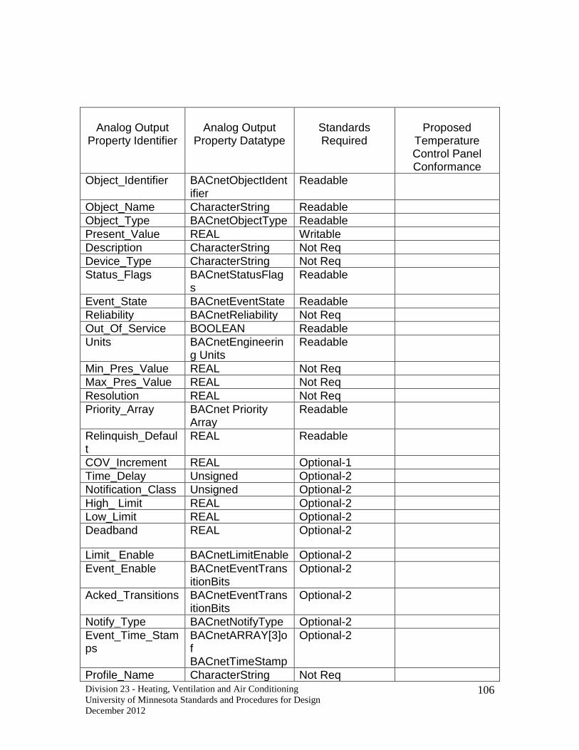
Division 23 - Heating, Ventilation and Air Conditioning
University of Minnesota Standards and Procedures for Design
December 2012
106
Analog Output
Property Identifier
Analog Output
Property Datatype
Standards Required
Proposed
Temperature Control Panel Conformance
Object_Identifier BACnetObjectIdentifier
Readable
Object_Name CharacterString Readable
Object_Type BACnetObjectType Readable
Present_Value REAL Writable
Description CharacterString Not Req
Device_Type CharacterString Not Req
Status_Flags BACnetStatusFlags
Readable
Event_State BACnetEventState Readable
Reliability BACnetReliability Not Req
Out_Of_Service BOOLEAN Readable
Units BACnetEngineering Units
Readable
Min_Pres_Value REAL Not Req
Max_Pres_Value REAL Not Req
Resolution REAL Not Req
Priority_Array BACnet Priority Array
Readable
Relinquish_Default
REAL Readable
COV_Increment REAL Optional-1
Time_Delay Unsigned Optional-2
Notification_Class Unsigned Optional-2
High_ Limit REAL Optional-2
Low_Limit REAL Optional-2
Deadband REAL Optional-2
Limit_ Enable BACnetLimitEnable Optional-2
Event_Enable BACnetEventTransitionBits
Optional-2
Acked_Transitions BACnetEventTransitionBits
Optional-2
Notify_Type BACnetNotifyType Optional-2
Event_Time_Stamps
BACnetARRAY[3]of BACnetTimeStamp
Optional-2
Profile_Name CharacterString Not Req

Division 23 - Heating, Ventilation and Air Conditioning
University of Minnesota Standards and Procedures for Design
December 2012
107
1 This property is required if the object supports COV reporting. (Not Required by the U of M) 2 These properties are required if the object supports intrinsic reporting. (Required by the U of M)

Division 23 - Heating, Ventilation and Air Conditioning
University of Minnesota Standards and Procedures for Design
December 2012
108
Analog Value
Property Identifier
Analog Value
Property Datatype
Standards Required
Proposed
Temperature Control Panel Conformance
Object_Identifier BACnetObjectIdentifier
Readable
Object_Name CharacterString Readable
Object_Type BACnetObjectType Readable
Present_Value REAL Readable-4
Description CharacterString Not Req
Status Flags BACnetStatusFlags Readable
Event_State BACnetEventState Readable
Reliability BACnetReliability Not Req
Out_Of_Service BOOLEAN Readable
Units BACnetEngineering Units
Readable
Priority Array BACnet Priority Array
Optional-1
Relinquish Default REAL Optional-1
COV_Increment REAL Optional-2
Time_Delay Unsigned Optional-3
Notification_Class Unsigned Optional-3
High_ Limit REAL Optional-3
Low_Limit REAL Optional-3
Deadband REAL Optional-3
Limit_ Enable BACnetLimitEnable Optional-3
Event_Enable BACnetEvent TransitionBits
Optional-3
Acked_Transitions BACnetEventTransitionBits
Optional-3
Notify_Type BACnetNotifyType Optional-3
Event_Time_Stamps
BACnetARRAY[3]of BACnetTimeStamp
Optional-3
Profile_Name CharacterString Not Req
1 If Present_Value is commandable, then both of these properties shall be present. 2 This property is required if the object supports COV reporting. (Not Required by the U of M) 3 These properties are required if the object supports intrinsic reporting. (Required by the U of M) 4 If Present_Value is commandable, then it is required to be writable. This property is required to be writable when Out_Of_Service is TRUE.

Division 23 - Heating, Ventilation and Air Conditioning
University of Minnesota Standards and Procedures for Design
December 2012
109
Binary Input
Property Identifier
Binary Input
Property Datatype
Standards Required
Proposed
Temperature Control Panel Conformance
Object_Identifier BACnetObject Identifier
Readable
Object_Name CharacterString Readable
Object_Type BACnetObject Type Readable
Present_Value REAL Readable-1
Description CharacterString Not Req
Device_Type CharacterString Not Req
Status_Flags BACnetStatusFlags Readable
Event_State BACnetEventState Readable
Reliability BACnetReliability Not Req
Out_Of_Service BOOLEAN Readable
Polarity BACnet Polarity Readable
Inactive_Text Character String Optional-2
Active_Text Character String Optional-2
Change_Of_State_Time BACnetDateTime Optional-3
Change_Of_State_Count
Unsigned Optional-3
Time_Of_State_Count_Reset
BACnetDateTime Optional-3
Elapsed_Active_Time Unsigned 32 Optional-4
Time_Of_Active_Time_Reset
BACnetDateTime Optional-4
Time_Delay Unsigned Optional-5
Notification_Class Unsigned Optional-5
Alarm_Value BACnetBinary PV Optional-5
Event_Enable BACnet Event TransitionBits
Optional-5
Acked_Transitions BACnetEventTransitionBits
Optional-5
Notify_Type BACnet NotifyType Optional-5
Event_Time_Stamps BACnetARRAY (3) of BACnetTime Stamp
Optional-5
Profile_Name CharacterString Not Req
1 This property is required to be writable when Out_Of_Service is TRUE.

Division 23 - Heating, Ventilation and Air Conditioning
University of Minnesota Standards and Procedures for Design
December 2012
110
2 If one of the optional properties Inactive_Text or Active_Text is present, then both of these properties shall be present. 3 If one of the optional properties Change_Of_State_Time, Change_Of_State_Count, or Time_Of_State_Count_Reset is present, then all of these properties shall be present. 4 If one of the optional properties Elapsed_Active_Time or Time_Of_Active_Time_Reset is present, then both of these properties shall be present. 5 These properties are required if the object supports intrinsic reporting. (Required by the U of M)

Division 23 - Heating, Ventilation and Air Conditioning
University of Minnesota Standards and Procedures for Design
December 2012
111
Binary Output
Property Identifier
Binary Output
Property Datatype
Standards Required
Proposed
Temperature Control Panel Conformance
Object_Identifier BACnetObject Identifier
Readable
Object_Name CharacterString Readable
Object_Type BACnetObjectType
Readable
Present_Value REAL Writable
Description CharacterString Not Req
Device_Type CharacterString Not Req
Status_Flags BACnetStatusFlags
Readable
Event_State BACnetEventState
Readable
Reliability BACnetReliability
Not Req
Out_Of_Service BOOLEAN Readable
Polarity BACnet Polarity Readable
Inactive_Text Character String Optional-1
Active_Text CharacterString Optional-1
Change_Of_State_Time
BACnetDateTime
Optional-2
Change_Of_State_Count
Unsigned Optional-2
Time_Of_State_Count_Reset
BACnetDateTime
Optional-2
Elapsed_Active_Time Unsigned 32 Optional-3
Time_Of_Active_Time_Reset
BACnetDateTime
Optional-3
Minimum_Off_Time Unsigned 32 Not Req
Minimum_On_Time Unsigned 32 Not Req
Priority_Array BACnetPriorityArray
Readable
Relinquish_Default BACnetBinaryPV
Readable
Time_Delay Unsigned Optional-4
Notification_Class Unsigned Optional-4
Feedback_Value BACnetBinaryPV
Optional-4
Event_Enable BACnetEvent TransitionBits
Optional-4

Division 23 - Heating, Ventilation and Air Conditioning
University of Minnesota Standards and Procedures for Design
December 2012
112
Acked_Transitions BACnetEvent TransitionBits
Optional-4
Notify_Type BACnetNotifyType
Optional-4
Event_Time_Stamps BACnetARRAY(3)of BACnetTimeStamp
Optional-4
Profile _Name CharacterString Not Req
1 If one of the optional properties Inactive_Text or Active_Text is present, then both of these properties shall be present. 2 If one of the optional properties Change_Of_State_Time, Change_Of_State_Count, or Time_Of_State_Count_Reset is present then all of these properties shall be present. 3 If one of the optional properties Elapsed_Active_Time or Time_Of_Active_Time_Reset is present, then both of these properties shall be present. 4 These properties are required if the object supports intrinsic reporting. (Required by the U of M)

Division 23 - Heating, Ventilation and Air Conditioning
University of Minnesota Standards and Procedures for Design
December 2012
113
Binary Value
Property Identifier
Binary Value
Property Datatype
Standards Required
Proposed
Temperature Control Panel Conformance
Object_Identifier BACnetObject Identifier
Readable
Object_Name CharacterString Readable
Object_Type BACnetObjectType
Readable
Present_Value REAL Readable-1
Description CharacterString Not Req
Status Flags BACnetStatusFlags
Readable
Event_State BACnetEventState
Readable
Reliability BACnetReliability
Not Req
Out_Of_Service BOOLEAN Readable
Inactive_Text CharacterString Optional-2
Active_Text CharacterString Optional-2
Change_Of_State_Time
BACnetDateTime
Optional-3
Change_Of_State_Count
Unsigned 32 Optional-3
Time_Of_State_Count_Reset
BACnetDateTime
Optional-3
Elapsed_Active_Time Unsigned 32 Optional-4
Time_Of_Active_Time_Reset
BACnetDateTime
Optional-4
Minimum_Off_Time Unsigned 32 Not Req
Minimum_On_Time Unsigned 32 Not Req
Priority_Array BACnetPriorityArray
Optional-5
Relinquish_Default BACnetBinaryPV
Optional-5
Time_Delay Unsigned Optional-6
Notification_Class Unsigned Optional-6
Alarm_Value BACnetBinaryPB
Optional-6
Event_Enable BACnetEvent TransitionBits
Optional-6
Acked_Transitions BACnetEventTransitionBits
Optional-6

Division 23 - Heating, Ventilation and Air Conditioning
University of Minnesota Standards and Procedures for Design
December 2012
114
Notify_Type BACnetNotifyType
Optional-6
Event_Time_Stamps BACnetARRAY[3]of BACnetTimeStamp
Optional-6
Profile_Name CharacterString Not Req
1 If Present_Value is commandable, then it is required to be writable. This property is required to be writable when Out_Of_Service is TRUE. 2 If one of the optional properties Inactive_Text or Active_Text is present, then both of these properties shall be present. 3 If one of the optional properties Change_Of_State_Time, Change_Of_State_Count, or Time_Of_State_Count_Reset is present, then all of these properties shall be present. 4 If one of the optional properties Elapsed_Active_Time or Time_Of_Active_Time_Reset is present, then both of these properties shall be present. 5 If present_Value is commandable, then both of these properties shall be present. 6 These properties are required if the object supports intrinsic reporting. (Required by the U of M)

Division 23 - Heating, Ventilation and Air Conditioning
University of Minnesota Standards and Procedures for Design
December 2012
115
Calendar
Property Identifier
Calendar
Property Datatype
Standards Required
Proposed
Temperature Control Panel Conformance
Object_Identifier BACnetObjectIdentifier
Readable
Object_Name CharacterString Readable
Object_Type BACnetObjectType Readable
Description CharacterString Not Req
Present_Value BOOLEAN Readable
Date List List of BACnetCalendarEntry
Readable
Profile_Name CharacterString Not Req

Division 23 - Heating, Ventilation and Air Conditioning
University of Minnesota Standards and Procedures for Design
December 2012
116
Device
Property Identifier
Device
Property Datatype
Standards Required
Proposed
Temperature Control Panel Conformance
Object_Identifier BACnetObjectIdentifier Readable
Object_Name CharacterString Readable
Object_Type BACnetObjectType Readable
System_Status BACnetDeviceStatus Readable
Vendor_Name CharacterString Readable
Vendor_Identifier Unsigned 16 Readable
Model Name CharacterString Readable
Firmware_Revision CharacterString Readable
Application_Software_Version
CharacterString Readable
Location CharacterString Not Req
Description CharacterString Not Req
Protocol_Version Unsigned Readable
Protocol_Revision Unsigned Readable
Protocol_Services_Supported
BACnetServicesSupported Readable
Protocol_Oject_Types_Supported
BACnetObjectTypesSupported
Readable
Object_List BACnetARRAY (N) of BACnet ObjectIdentifier
Readable
Max_APDU_Length_Accepted
Unsigned Readable
Segmentation_Supported BACnet Segmentation Readable
Max_Segments_Accepted Unsigned Optional-1
VT_Classes_Supported List of BACnet VTClass Optional-2
Active_VT_Sessions List of BACnetVTSession Optional-2
Local_Time Time Optional-3,4
Local_Date Date Optional-3,4
UTC_Offset INTEGER Optional-4
Daylight_Savings_Status BOOLEAN Optional-4
APDU_Segment_Timeout Unsigned Optional-1
APDU_Timeout Unsigned Readable
Number_Of_APDU_Retries Unsigned Readable
List_Of_Session_Keys List of BACnetSessionKey Not Req
Time_Synchronization_Recipients
List of BACnetRecipient Optional-5

Division 23 - Heating, Ventilation and Air Conditioning
University of Minnesota Standards and Procedures for Design
December 2012
117
Max_Master Unsigned (1..127) Optional-6
Max_Info_Frames Unsigned Optional-6
Device_Address_Binding List of BACnetAddressBinding
Readable
Database_Revision Unsigned Readable
Configuration_Files BACnetARRAY (N) of BACnet Object Identifier
Optional-7
Last_Restore_Time BACnetDateTime Optional-7
Backup_Failure_Timeout Unsigned 16 Optional-8
Active_COV_Subscriptions List of BACnetCOVSubscriptions
Optional-9
Profile_Name CharacterString Not Req
1 Required if segmentation of any kind is supported. 2 If one of the properties VT_Classes_Supported or Active_VT_Sessions is present, then both of these properties shall be present. Both properties are required if support for VT Services is indicated in the PICS. 3 If the device supports the execution of the TimeSynchronization service, then these properties shall be present. 4 If the device supports the execution of the UTCTimeSynchronization service, then these properties shall be present. 5 Required if PICS indicates that this device is a Time Master. If present, this property shall be writable. 6 These properties are required if the device is an MS/TP master node. (The U of M allows MS/TP at the building subLAN only) 7 These properties are required if the device supports the backup and restore procedures. 8 This property must be present and writable if the device supports the backup and restore procedures 9 This property is required if the device supports execution of either the SubscribeCOV or SubscribeCOV Property service.

Division 23 - Heating, Ventilation and Air Conditioning
University of Minnesota Standards and Procedures for Design
December 2012
118
Multi-state Input Property Identifier
Multi-state Input Property Datatype
Standards Required
Proposed Temperature Control Panel Conformance
Object_Identifier BACnetObjectIdentifier Readable
Object_Name CharacterString Readable
Object_Type BACnetObjectType Readable
Present_Value Unsigned Readable-1
Description CharacterString Not Req
Device_Type CharacterString Not Req
Status_Flags BACnetStatusFlags Readable
Event_State BACnetEventState Readable
Reliability BACnetReliability Optional-2
Out_Of_Service BOOLEAN Readable
Number_Of_States Unsigned Readable
State_Text BACnetARRAY(N) of CharacterString
Not Req
Time_Delay Unsigned Optional-3
Notification_Class Unsigned Optional-3
Alarm_Values List of Unsigned Optional-3
Fault_Values List of Unsigned Optional-3
Event_Enable BACnetEventTransitionBits Optional-3
Acked_Transitions BACnetEventTransitionBits Optional-3
Notify_Type BACnetNotifyType Optional-3
Event_Time_Stamps BACnetARRAY(3) of BACnetTimeStamp
Optional-3
Profile_Name CharacterString Not Req
1 This property is required to be writable when Out_Of_Service is TRUE. 2 This property shall be required if Fault_Values is present. 3 These properties are required if the object supports intrinsic reporting (Required by the U of M)

Division 23 - Heating, Ventilation and Air Conditioning
University of Minnesota Standards and Procedures for Design
December 2012
119
Multi-state Output Property Identifier
Multi-state Output Property Datatype
Standards Required
Proposed Temperature Control Panel Conformance
Object_Identifier BACnetObjectIdentifier
Readable
Object_Name CharacterString Readable
Object_Type BACnetObjectType
Readable
Present_Value Unsigned Writable
Description CharacterString Not Req
Device_Type CharacterString Not Req
Status_Flags BACnetStatusFlags
Readable
Event_State BACnetEventState
Readable
Reliability BACnetReliability Not Req
Out_Of_Service BOOLEAN Readable
Number_Of_States
Unsigned Readable
State_Text BACnetARRAY(N) of CharacterString
Not Req
Priority_Array BACnetPriorityArray
Readable
Relinquish_Default
Unsigned Readable
Time_Delay Unsigned Optional-1
Notification_Class Unsigned Optional-1
Feedback_Value Unsigned Optional-1
Event_Enable BACnetEventTransitionBits
Optional-1
Acked_Transitions BACnetEventTransitionBits
Optional-1
Notify_Type BACnetNotifyType Optional-1
Event_Time_Stamps
BACnetARRAY(3) of BACnetTimeStamp
Optional-1
Profile_Name CharacterString Not Req
1 These properties are required if the object supports intrinsic reporting. (Required by the U of M)

Division 23 - Heating, Ventilation and Air Conditioning
University of Minnesota Standards and Procedures for Design
December 2012
120
Multi-state Value Property Identifier
Multi-state Value Property Datatype
Standards Required
Proposed Temperature Control Panel Conformance
Object_Identifier BACnetObjectIdentifier
Readable
Object_Name CharacterString Readable
Object_Type BACnetObjectType
Readable
Present_Value Unsigned Readable-1
Description CharacterString Not Req
Status_Flags BACnetStatusFlags
Readable
Event_State BACnetEventState
Readable
Reliability BACnetReliability Optional-2
Out_Of_Service BOOLEAN Readable
Number_Of_States
Unsigned Readable
State_Text BACnetARRAY(N) of CharacterString
Not Req
Priority_Array BACnetPriorityArray
Optional-3
Relinquish_Default
Unsigned Optional-3
Time_Delay Unsigned Optional-4
Notification_Class Unsigned Optional-4
Alarm_Values List of Unsigned Optional-4
Fault_Values List of Unsigned Optional-4
Event_Enable BACnetEventTransitionBits
Optional-4
Acked_Transitions BACnetEventTransitionBits
Optional-4
Notify_Type BACnetNotifyType Optional-4
Event_Time_Stamps
BACnetARRAY(3) of BACnetTimeStamp
Optional-4
Profile_Name CharacterString Not Req
1 If Present_Value is commandable, then it is required to also be writable. This property is required to be writable when Out_Of_Service is TRUE. 2 This property shall be required if Fault_Values is present

Division 23 - Heating, Ventilation and Air Conditioning
University of Minnesota Standards and Procedures for Design
December 2012
121
3 If Present_Value is commandable, then both of these properties shall be present. 4 These properties are required if the object supports intrinsic reporting. (Required by the U of M)

Division 23 - Heating, Ventilation and Air Conditioning
University of Minnesota Standards and Procedures for Design
December 2012
122
Notification Class Property Identifier
Notification Class Property Datatype
Standard
s Required
Proposed Temperat
ure Control Panel
Conformance
Object_Identifier BACnetObjectIdentifier Readable
Object_Name CharacterString Readable
Object_Type BACnetObjectType Readable
Description CharacterString Not Req
Notification_Class Unsigned Readable
Priority BACnetARRAY(3)of Unsigned
Readable
Ack_Required BACnetEventTransitionBits Readable
Recipient List List of BACnetDestination Readable
Profile Name CharacterString Not Req

Division 23 - Heating, Ventilation and Air Conditioning
University of Minnesota Standards and Procedures for Design
December 2012
123
Schedule Property Identifier
Schedule Property Datatype
Standards Required
Proposed Temperature Control Panel Conformance
Object_Identifier BACnetObjectIdentifier Readable
Object_Name CharacterString Readable
Object_Type BACnetObjectType Readable
Present_Value Any Readable
Description CharacterString Not Req
Effective_Period BACnetDateRange Writable-1
Weekly_Schedule BACnetARRAY(7)of BACnetDailySchedule
Writable-1
Exception_Schedule BACnetARRAY(N)of BACnetSpecialEvent
Writable-1
List_Of_Object_Property_ References
List of BACnetDeviceObjectPropertyReference
Readable
Priority_For_Writing Unsigned (1..16) Readable
Profile_Name CharacterString Not Req
1- Writable indicates a requirement of the U of M which is over and above BACnet conformance requirements.

Division 23 - Heating, Ventilation and Air Conditioning
University of Minnesota Standards and Procedures for Design
December 2012
124
Trend Property Identifier
Trend Property Datatype
Standards Required
Proposed Temperature
Control Panel
Conformance
Object_Identifier BACnetObjectIdentifier Readable
Object_Name CharacterString Readable
Object_Type BACnetObjectType Readable
Description CharacterString Not Req
Log_Enable BOOLEAN Writable
Start_Time BACnetDateTime Optional-1,2
Stop_Time BACnetDateTime Optional-1,2
Log_DeviceObjectProperty
BACnetDeviceObjectPropertyReference
Optional-1
Log_Interval Unsigned Optional-1,2
COV_Resubscription_Interval
Unsigned Not Req
Client_COV_Increment BACnetClientCOV Not Req
Stop_When_Full BOOLEAN Readable
Buffer_Size Unsigned32 Readable
Log_Buffer List of BACnetLogRecord
Readable
Record_Count Unsigned32 Writable
Total_Record_Count Unsigned32 Readable
Notification_Threshold Unsigned32 Optional-3
Records_Since_Notification
Unsigned32 Readable-3
Last_Notify_Record Unsigned32 Readable-3
Event_State BACnetEventState Readable
Notification_Class Unsigned Readable-3
Event_Enable BACnetEventTransitionBits
Readable-3
Acked_Transitions BACnetEventTransitionBits
Readable-3
Notify_Type BACnetNotifyType Readable-3
Event_Time_Stamps BACnetARRAY[3] of BACnetTimeStamp
Readable-3
Profile_Name CharacterString Not Req
1These properties are required to be present if the monitored property is a BACnet property. 2 If present, these properties are required to be writable.

Division 23 - Heating, Ventilation and Air Conditioning
University of Minnesota Standards and Procedures for Design
December 2012
125
3 These properties are required if the object supports intrinsic reporting. (Required by U of M)
U of M Minimum Protocol Implementation Conformance (PIC) for BACnet
Building Controller
This PIC is used to describe what parts of the BACnet standard need to be implemented
at U of M in order to achieve interoperability. It is the intention of the U of M to require
temperature control products to conform to select BACnet standards in order to utilize a
single Master Operator Workstation.
BACnet Protocol Implementation Conformance Statement
Date: _April 1st 2005
BACnet Standardized Device Profile (Annex L):
All proposed devices show must meet all U of M BACnet requirements:
BACnet Building Controller (B-BC)
BACnet Advanced Application Controller (B-AAC)
BACnet Application Specific Controller (B-ASC)
BACnet Smart Sensor (B-SS)
BACnet Smart Actuator (B-SA)
BACnet Interoperability Building Blocks Supported (Annex K):
Segmentation Capability:
Segmented requests supported
The U of M does not require segmentation capability. Some vendors use this for
larger messages. If the vendor segments requests then it must conform to the
BACnet standard.
Segmented responses supported window Size
Varies depending on usage. Not stipulated by the U of M.
Standard Object Types Supported:
The U of M will require support for the following Standard ANSI/ASHRAE 135-2004
BACnet objects. See the object tables above for Individual Object property requirements.
BACnet Object 2004 Standard
Analog Input Vendor required to support object
Analog Output Vendor required to support object
Analog Value Vendor required to support object
Average Not required
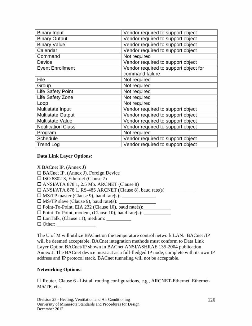
Division 23 - Heating, Ventilation and Air Conditioning
University of Minnesota Standards and Procedures for Design
December 2012
126
Binary Input Vendor required to support object
Binary Output Vendor required to support object
Binary Value Vendor required to support object
Calendar Vendor required to support object
Command Not required
Device Vendor required to support object
Event Enrollment Vendor required to support object for command failure
File Not required
Group Not required
Life Safety Point Not required
Life Safety Zone Not required
Loop Not required
Multistate Input Vendor required to support object
Multistate Output Vendor required to support object
Multistate Value Vendor required to support object
Notification Class Vendor required to support object
Program Not required
Schedule Vendor required to support object
Trend Log Vendor required to support object
Data Link Layer Options:
X BACnet IP, (Annex J)
BACnet IP, (Annex J), Foreign Device
ISO 8802-3, Ethernet (Clause 7)
ANSI/ATA 878.1, 2.5 Mb. ARCNET (Clause 8)
ANSI/ATA 878.1, RS-485 ARCNET (Clause 8), baud rate(s) ____________
MS/TP master (Clause 9), baud rate(s):
MS/TP slave (Clause 9), baud rate(s):
Point-To-Point, EIA 232 (Clause 10), baud rate(s):
Point-To-Point, modem, (Clause 10), baud rate(s):
LonTalk, (Clause 11), medium: __________
Other:
The U of M will utilize BACnet on the temperature control network LAN. BACnet /IP
will be deemed acceptable. BACnet integration methods must conform to Data Link
Layer Option BACnet/IP shown in BACnet ANSI/ASHRAE 135-2004 publication
Annex J. The BACnet device must act as a full-fledged IP node, complete with its own IP
address and IP protocol stack. BACnet tunneling will not be acceptable.
Networking Options:
Router, Clause 6 - List all routing configurations, e.g., ARCNET-Ethernet, Ethernet-
MS/TP, etc.

Division 23 - Heating, Ventilation and Air Conditioning
University of Minnesota Standards and Procedures for Design
December 2012
127
Annex H, BACnet Tunneling Router over IP (This protocal is not acceptable for any U
of M application)
BACnet/IP Broadcast Management Device (BBMD)
BBMD support registrations by Foreign Devices? X Yes No
The U of M requires Foreign Device Registration. If the BACnet Building
Controller proposed by the temperature controls contractor does not support
registrations by Foreign Device than the temperature controls contractor is required
to supply a 3rd
party device (BACnet router) or equivalent to perform this task.
BBMD (BACnet Broadcast Management Device) receives broadcast messages on
one subnet and forwards them to another subnet.
The U of M requires BBMD support
Character Sets Supported:
Indicating support for multiple character sets does not imply that they can all be
supported simultaneously.
X ANSI X3.4 IBM
/Microsoft
DBCS ISO 8859-1
ISO 10646 (UCS-2) ISO 10646 (UCS-4) JIS C 6226
The U of M requires ANSI X3.4 Support
All ANSI/ASHRA 135-2004 required standard object properties will be supported by the
temperature controls contractor BACnet device(s). Standard object optional properties
will be supported if they are a requirement of any object listed above. Unsolicited
change-of-value notification is required. All objects and object properties will be
supported so that alarms are sent from the temperature control contractors BACnet
building controller without having to be solicited from the U of M Master BACnet
Operators Workstation (B-OWS) or Master History PC.
End of 23 09 00 Instrumentation and Control for HVAC
23 21 13 Hydronic Piping and Heating Piping
Pipe
1.1. PROHIBITED: Direct-buried steam and steam condensate pipe.
1.2. Tie-ins to New or Existing Mains
1.2.1. Prohibited: Stub-ins when connecting to new or existing mains.
1.2.2. Branch lines up to and including 10 inches in diameter that are at
least two sizes smaller than the mains may be tied-in using reducing tees
or qeldolets.

Division 23 - Heating, Ventilation and Air Conditioning
University of Minnesota Standards and Procedures for Design
December 2012
128
1.2.3. Branch sizes greater than 10 inches in diameter must be tied-in with
tees.
1.2.4. Connections to piping in university tunnels shall have appropriate
offsets to maintain pipe stress within acceptable limits.
1.3. Steel Pipe
1.3.1. General
1.3.1.1. Galvanized steel pipe shall be at least minimum standard
weight.
1.3.1.2. Standard weight and extra heavy black steel pipe shall be
A53B, A106B, A120 or A135 welded or seamless construction as
indicated for specific applications.
1.3.2. Steam pipe shall be minimum standard weight ASTM A53B
seamless or A106B.
1.3.3. Steam condensate pipe shall be minimum Schedule 80 ASTM A53B
seamless or A106B.
1.4. Copper Pipe
1.4.1. Prohibited: Soft annealed copper.
1.4.2. Type ‘K’ for gas and HWS&R under slabs serving around entrance
ways. Type ‘L’ copper pipe for all piping within the building.
1.5. Plastic Pipe
1.5.1 Prohibited: Plastic piping is not allowed in the hydronic systems.
1.5.2 HDPE: is approved for underground chilled water systems.
1.5.3 Pex: Pex piping is not allowed.
1.6. Glass Pipe: Borosilicate glass drain line shall be specified for use in corrosive
waste systems and corrosive vent systems.
Pipe Fittings
1.1. General Requirements
Division 23 - Heating, Ventilation and Air Conditioning
University of Minnesota Standards and Procedures for Design
December 2012
129
1.1.1. Prohibited: Couplings normally furnished with lengths of pipe used
to install threaded piping.
1.1.2. Standard weight steel, malleable or drainage couplings shall be used
according to application.
1.1.3. Specify extruded or wrought copper fittings in copper piping
systems.
1.2. Specify 300# black or galvanized steel unions for steel piping systems.
1.2.1. Specify butt-weld or socket-weld fittings consistent with the piping
system. For example, specify standard weight fittings with standard
weight pipe. Welding flanges shall be weld neck or slip-on with pressure
to match the system as required.
1.2.2. For takeoffs from black steel piping mains and headers 2-1/2 inches
and larger, where pipe reduction is two sizes or more, specify weldolets or
sockolets in lieu of reducing weld tees subject to field inspection prior to
connection to branch lines. Manifolds must use reducing weld tees.
1.2.3. Specify isolating/dielectric unions or isolating/dielectric flanges
wherever iron and copper or iron and brass piping and equipment are used
together in a water piping system. The A/E shall clearly show on drawings
all locations for isolating/dielectric unions.
1.3. Low Pressure Steam Condensate
1.3.1. Fittings that are 2 inches and smaller shall be ANSI Class 150, black
malleable iron threaded. Fittings more than 2 inches shall be butt weld.
1.3.2. Unions that are 2 inches and smaller shall be ANSI Class 150, black
malleable iron threaded.
1.3.3. Flanges shall be ANSI Class 150, forged steel weld neck with B7
studs and A194 extra heavy hex nuts.
1.4. High Pressure Steam Condensate
3.4.1. Fittings that are 2 inches and smaller shall be ANSI Class 3000,
forged steel, socket weld. Fittings more than 2 inches shall be butt or
socket weld.
3.4.2. Unions that are 2 inches and smaller shall be ANSI Class 3000,
forged steel, socket weld.

Division 23 - Heating, Ventilation and Air Conditioning
University of Minnesota Standards and Procedures for Design
December 2012
130
3.4.3. Flanges shall be ANSI Class 300, forged steel weld neck with B7
studs and A194 extra heavy nuts.
Strainers/Steam and Hydronic Systems
1.1. “Y” type strainers with screens shall be installed ahead of all traps (except
radiator traps), control valves, pressure-reducing valves and other devices where
debris may cause malfunction.
1.2. Strainers shall be installed so the equipment isolating valves also isolate the
strainers.
1.3. Strainers for low-pressure steam shall be ANSI Class 150, and shall have
brass screen.
1.3.1. Strainers for low-pressure steam smaller than 3 inches shall have
blow down plugs installed with Teflon pipe dope.
1.3.2. Strainers for low-pressure steam 3 inches and larger shall be
complete with valve, nipple and pipe cup on blow down.
1.4. Strainers for high-pressure steam above 15 psig shall have 16-gauge mesh,
stainless steel screen with forged steel bodies, ANSI Class 300 with blow down
valves.
23 21 23 Hydronic Pumps
Pumping Systems for Chilled Water Plants
1. General Requirements for Chilled Water Pumping Systems
1.1. Each condenser water-pumping system shall be designed with a stand-by
pump.
1.2. The basic chilled water pumping system shall consist of a primary system
with constant flow pumps that only serve the chiller. A secondary system that
consists of pumps with VFD shall supply chilled water to the building.
1.3. The A/E shall determine if a tertiary pumping system is optional based upon
the pumping needed for the cluster of buildings.
1.4. Each primary and secondary system shall have a stand-by pump.
2. Chilled Water Pumping System Control Sequence

Division 23 - Heating, Ventilation and Air Conditioning
University of Minnesota Standards and Procedures for Design
December 2012
131
2.1. Secondary Chilled Water Pump Control: The chiller controls shall regulate
when the secondary chilled water pumps start and stop. The chiller plant controls
shall modulate the VFDs for the secondary pumps to maintain the pressure
differential between the secondary supply and return mains. The chiller controls
shall monitor the secondary differential pressure sensors where the
secondary/tertiary connects at each building. The chiller controls shall select the
pressure sensor with the lowest reading and modulate the VFD to maintain the
differential pressure set point.
2.2. Tertiary Chilled Water Pump Control
2.2.1. The building control system, rather than the chiller cluster controls,
shall start and stop the tertiary chilled water pumps. The building control
system also shall modulate the VFD to maintain a differential between the
building supply and return mains. The differential pressure sensors shall
be located where it is most difficult hydraulically to get water to chilled
water coils. Some buildings may require more than one differential
pressure sensor depending on the piping layout.
2.2.2. The building controls shall monitor the chilled water return
temperature that leaves the building and modulate a two-way control valve
on the return water piping to maintain the chilled water return set point of
58 degrees F.
3. Condenser Water Pumping System Control Sequence:
The chiller panel shall start the condenser water pumping system and run as long
as the chiller panel is energized.
23 22 00 Steam and Condensate Piping and Pumps
Utility Heating Piping Systems
1. Steam Piping Systems
1.1. This section pertains to standards for designing and testing campus steam
distribution and steam condensate piping systems, and connecting to university
buildings. The campus steam distribution system extends from the district meters
located near the heating plants up to and including the gate valves immediately
upstream of the building steam pressure reducing stations. The campus steam
condensate piping system extends from the district meters located near the heating
plants up to the building condensate meters.
1.2. The methods of design and construction shall be in accordance with the State
of Minnesota Code for High Pressure Piping, Chapter 5230, and ANSI B31.1 for
high-pressure piping, and shall be in accordance with the Minnesota Department
of Administration State Building Code, Mechanical Systems, Chapter 1345 for
low-pressure piping.

Division 23 - Heating, Ventilation and Air Conditioning
University of Minnesota Standards and Procedures for Design
December 2012
132
1.3. Whenever university standards differ from applicable codes, the more
stringent requirement shall be followed. In case of dispute, the authority having
jurisdiction is the high-pressure piping inspector, who is employed by the
Minnesota Department of Labor and Industry for high-pressure steam. The
University Building Code official is the authority having jurisdiction for low-
pressure steam condensate.
1.4. High-pressure steam systems and components shall be designed for 250 psig
at 500 degrees F for Minneapolis and St. Paul.
1.5. A sample of high-pressure steam system welds shall be x-rayed before
hydrostatic testing. The engineer and owner shall determine the sample number.
The contractor shall notify the university and any legal officers at least 24 hours
prior to hydrostatic testing. The university shall inspect the piping systems prior
to testing, and shall forward a punch list of items to be corrected, if necessary, to
the contractor. The contractor shall address the punch list items, forward a written
report to the university that indicates that all items on the punch list have been
satisfied and request permission from the university to proceed with the
hydrostatic testing. Upon receiving permission, the contractor shall test the
system. A hydrostatic test shall be conducted on campus steam condensate return
piping at 1-1/2 times the design pressure or 150 psig, whichever is greater, prior
to the installation of any insulating material. Design pressure for high-pressure
steam distribution systems shall be considered to be 250 psig. Upon passing the
hydrostatic test, the piping insulation shall be applied. The contractor shall
remove any temporary drains and/or vents.
1.6. Startup: When the contractor is finished with construction, testing and
completing the punch list, university personnel shall start the system. The
contractor shall have one or more pipefitters in attendance during system startup.
Once the system is up to full pressure and flow, the university and the contractor’s
pipefitters shall inspect the system for leaks, excessive movement and proper
support. If required, the university shall shut down the system for the contractor to
repair/revise the system. Then the startup procedure shall be repeated until the
university accepts the system as-built.
1.7. Documentation: The design specifications shall call for the contractor to
furnish the proper documentation to Steam Utilities on engineered items such as
pumps, valves and piping expansion/contraction parts that include expansion
joints, controls and meters. Documentation shall include assembly drawings, parts
lists, calibration certificates, wiring diagrams, maintenance instructions and
recommended spare parts lists.
1.8. Typical flash tank installation shall be per the sketch on the following page.

Division 23 - Heating, Ventilation and Air Conditioning
University of Minnesota Standards and Procedures for Design
December 2012
133
1.9. Typical steam trap installations shall be per the sketch on the following page.
High-pressure steam traps shall be Plenty Velan Model 250 or university-
approved equal.
1.10. Typical steam PRV station installation shall be per the sketch on the
following page.
1.11. Steam pipes that require welding shall be accomplished in the same method
as identified in the following ASME welding procedure specification.
1.12 Traps:
All traps shall have tags showing the model number and orifice size.
1.12.1 Prohibited: Cast-iron traps on high-pressure steam systems.
Thread O Let connections to steam mains on high-pressure
steam systems.
1.12.2. All steam mains shall have properly designed and detailed drip trap
assemblies shown with a maximum spacing between drip trap assemblies to be
200 linear feet. Steam mains shall be dripped whenever the piping makes
elevation changes. Consideration shall be given to looped mains because flow
may be bi-directional.
1.12.3. Maintain 4 inches minimum clearance between threaded dirt leg cap and
any obstruction.
1.12.4. Low Pressure Steam Systems
1.12.4.1. Specify Armstrong Series 880 or university-approved equal
inverted bucket traps or F & T traps with integral strainers and thermic
vent (in all cases) such as drip lines, unit heaters and heating coils where
radiator thermostatic traps are too small. Install in all instances except
radiation. A safety factor of two shall be used when determining trap size.
1.12.4.2. Radiator traps shall be thermostatic, siphon multiple bellows type
with replaceable stainless steel seats and discs. The traps shall close upon
failure.
1.12.5 High Pressure Steam Systems
1.12.5.1. Traps shall be stacked bimetallic thermostatic with a minimum
orifice size of 3/8 inches. Specify Plenty Velan type TS thermostatic steam
trap or university-approved equal.
1.12.5.2. Every trap assembly shall be designed for ease of trap testing by
including a test valve after the check valve

Division 23 - Heating, Ventilation and Air Conditioning
University of Minnesota Standards and Procedures for Design
December 2012
134
Note: Use vertical ASME 300# tank
Vent to Outside
Steam Flash Tank
LP Steam
Condensate TrapStrainer
Test ValveBlow Down
Valve
HP Condensate
Typical Flash Tank Detail
Pressure Gauge
Thermometer
Vent to Outside
Steam Flash Tank
LP Steam
Condensate TrapStrainer
Test ValveBlow Down
Valve
HP Condensate
Typical Flash Tank Detail
Pressure Gauge
Thermometer

Division 23 - Heating, Ventilation and Air Conditioning
University of Minnesota Standards and Procedures for Design
December 2012
135
Note: Traps with or without strainers shall have an inline strainer upstream of the trap.
Trap
CondensateTest Port
Strainer
w/blow down
Minimum 34" Diameter
Main Steam Pipe
Welded system to
second valveDirt Leg
Minimum 2" Diameter or
Full Size
Typical Steam Trap Detail
NOTE:
High Pressure - All welded construction except valves, strainers, traps
Low Pressure - Screwed fittings allowed 2" and under
12" minimum (bottom of
main to trap take off)

Division 23 - Heating, Ventilation and Air Conditioning
University of Minnesota Standards and Procedures for Design
December 2012
136
Note: Globe bypass valve shall be Klinger/Piston type or equal 3” and under and
Vanessa triple offset butterfly valve for 4” and above.
Class 300
NOTE:
- All welded construction except valves, strainers and traps
High Pressure
Steam
Dirt Leg
Class 300 (Typical)
Gravity Condensate (Typical)
Test Port (Typical)
Strainer w/blow down (Typical)
Class 150
Minimum 2" diameter
or fullsize (typical)
Class 300
Safety relief
Class 150
Vent to atmosphere
(outside)
Drip pan elbow
Typical Steam PRV Station
Dirt Leg
Low Pressure Steam
TT
Reducer (Typ)
Gravity
Condensate
(typical)Strainer
w/blow down
(Typical)
Flanged (Typ)
Globe Valve

Division 23 - Heating, Ventilation and Air Conditioning
University of Minnesota Standards and Procedures for Design
December 2012
137
ASME Welding Procedure Specification (Page 1)

Division 23 - Heating, Ventilation and Air Conditioning
University of Minnesota Standards and Procedures for Design
December 2012
138
ASME Welding Procedure Specification (Page 2)

Division 23 - Heating, Ventilation and Air Conditioning
University of Minnesota Standards and Procedures for Design
December 2012
139
23 25 00 HVAC Water Treatment
Water Treatment for Open and Closed Loops
1. Chemical Treatment for Open Loop Systems
1.1. Prohibited: Chemicals with powder and pellets.
1.2. The A/E shall specify a chemical water treatment system for each open loop.
The system specified shall include equipment, piping, tubing, inter-connecting
components and electrical controls as detailed in this section.
1.3. The minimum system requirements for open loops shall include all controls,
tanks, pumps, sensors, probes, analyzers, and valves necessary to perform and
service the following water treatment functions:
A. Automatic control of cooling tower bleed off
B. Automatic control of chemical treatment for scale and corrosion
C. Automatic control of biocide treatment
1.4. The A/E shall specify a water meter with a contacting head in the make up
line and a solenoid valve to measure water usage and control chemical feed in the
cooling tower. Provide a Y strainer upstream from water meter and solenoid
valve. It shall be supplied and positioned so water reading can be done remotely.
Local authorities shall approve the water meter. Specify Master Meters or
university-approved equal.
1.5. The A/E shall specify a water meter with a solenoid valve in the cooling
tower blow down line to measure water discharge. The specified meter shall
comply with local minimum code requirements. Provide a Y strainer upstream
from the water meter and solenoid valve. The meter must be in a position and
location so it can be easily read from the floor. It also shall be supplied so water
reading can be done remotely. Local authorities shall approve the water meter.
Specify Master Meters or university-approved equal.
1.6. The A/E shall specify a microprocessor-based conductivity controller that
controls bleed off, feeds the corrosion and scale inhibitor via a water meter in the
make-up water line that activates a pulse timer, alternates with a dual 28-day
biocide program and handles two water meters. The recommended water meter
manufacturer is Pulsatrol Plus Series Model MCT210BCF or university-approved
equal.
1.7. The A/E shall specify the liquid diaphragm metering pumps with adjustable
stroke and speed to feed biocides and the corrosion and scale inhibitor. The
pumps must be able to handle the design pressure and gpm for the specified
system. The recommended manufacturer is LMI or university-approved equal.

Division 23 - Heating, Ventilation and Air Conditioning
University of Minnesota Standards and Procedures for Design
December 2012
140
1.8. A corporation stop injector shall be provided at each point of injection in the
system.
1.9. The rack shall include a strainer, shut-off valves and a flow-regulating orifice
that are designed to produce 5 gpm.
1.10. The A/E shall specify that once the cooling tower is turned over to the
university, the university is responsible for the chemical treatment of the system.
No chemical treatment contract with the contractor or with an outside vendor is to
be specified for the warranty period. The university shall purchase all chemicals
necessary for the chemical treatment of the system.
1.11. The A/E shall specify that the water treatment supplier at the university is
responsible for cleaning and disinfecting open loop systems. The supplier shall
clean and disinfect them before they become operational. The supplier shall meet
the minimum requirements that DEHS defines for disinfecting. This specification
shall be included in the contractor's bid, and this activity must be coordinated with
the applicable zone.
2. Chemical Treatment for Closed Loop Systems
2.1. The A/E shall specify the necessary equipment for the chemical treatment of
the closed loop systems based on the following requirements:
2.1.1. The university shall purchase all chemicals necessary for the
chemical treatment of the system.
2.1.2. Each heating and cooling closed loop system shall be provided with
a one-shot feeder with an air-release valve, sized for the system to be
served and rated for a pressure of 300 psig. The minimum size of the
feeder shall be 5 gallons.
2.1.3. Propylene or ethylene glycol can be used where systems are
susceptible to freezing, provided the toxicity of the solution is consistent
with safety regulations. The minimum concentration of any glycol solution
shall be 20 percent. There can be no connections between systems with a
glycol/water mixture and systems with only water, which includes systems
used as stand by. All glycol provided for the system shall be HVAC grade,
Dowtherm, Dowfrost or university-approved equal.
23 30 00 HVAC Air Distribution
1. General

Division 23 - Heating, Ventilation and Air Conditioning
University of Minnesota Standards and Procedures for Design
December 2012
141
1.1. Design supply and return air systems to minimize short-circuiting supply air
to the return air system. The A/E shall include a schedule of ventilation efficiency
on the contract documents for rooms occupied by more than five people.
Ventilation efficiency shall be no less than 75 percent. Ventilation efficiency shall
be calculated in accordance with the most recent edition of ASHRAE 62-92.
Refer to Program Information/Requirements, Basic Design Requirements to
determine proper design in regards to air regulations and emissions.
1.2. To distribute outdoor air to people in the occupied spaces, supply and return
air shall be fully ducted.
1.3. Specify and witness duct leakage tests on supply and exhaust systems. The
design engineer and the university shall determine the frequency and extent of
testing.
1.4. To improve rigidity and tightness of construction, fabricate ductwork in
accordance with the most recent edition of the SMACNA standards.
1.5. The A/E shall coordinate the location, size and type of louvers, roof intake
and relief hoods. The size of each intake shall be based upon the manufacturer's
criteria for eliminating rain, snow or carry over into the air-handling system.
2. Ductwork Material
2.1. Prohibited: Fiberglass ductwork.
2.2. Fabricate ductwork from G-90 coated galvanized steel. Spunglass fiberglass
ductwork may be used underground. Stainless steel ducts may be required for
exhaust applications based on the use.
2.3. Gauge stickers or stamps shall be provided on each section of duct. In lieu of
stickers, gauge can be printed on the ductwork.
2.4. Supply and return air shall be fully ducted. Exceptions are special
applications such as in computer rooms, clean air rooms and dry rooms.
3. Minimum Supply Duct Size: Ducts shall be minimum 6 inches by 6 inches or 6 inches
round unless university-approved.
4. Ductwork Construction
4.1. Prohibited: Pipe or any other type of obstruction passing through a duct.
4.2. Provide a minimum of three duct diameters from fan inlet or discharge before
transition or elbows.

Division 23 - Heating, Ventilation and Air Conditioning
University of Minnesota Standards and Procedures for Design
December 2012
142
4.3. Duct connections shall be made with 30-degree to 45-degree takeoffs in the
direction of airflow.
4.4. Flexible duct length shall not exceed 6 feet. Limit total sag to less than 1/2-
inch per foot. Minimize bends in flexible duct. Limit total bends on one branch to
180 degrees. Between takeoff and termination, provide a minimum 6-inch overlap
where flexible duct connects to sheet metal duct or an air distribution device.
Minimum flexible duct size shall be 6 inches.
4.5. Each intake shall be sized based on the manufacturer’s criteria for eliminating
rain and snow from penetrating or carrying over into the air-handling system.
5. Sealing at Floors and Walls
5.1. Fire-stopping/sealant shall be installed in accordance with the requirements of
Division 7 - Thermal and Moisture Protection.
5.2. The A/E shall coordinate the sealing of floor and wall penetrations.
6. Special Exhaust System
6.1. Special purpose exhaust devices shall be designed with reference to
“Industrial Ventilation: A Manual of Recommended Practice by the American
Conference of Government Industrial Hygienists.” Use the current edition.
6.2. Refer to Division 13 00 30 - Food Service Construction Guide.
7. Duct Hangers and Supports
7.1. All ventilation ducts and related piping shall be independently supported
from the building structure. Cable hanging systems are approved as long as these
are used per manufacturer’s installation recommendations.
7.2. Horizontal ducts 48 inches or wider shall be rigidly and securely supported
with angle-iron trapeze hangers under the duct, according to SMACNA standards.
7.3. Structural members shall support all vertical ductwork at each floor.
7.4. All fastenings and hardware for galvanized ductwork and sheet metal shall be
cadmium-plated.
8. Manual Dampers
8.1. Specify and show all dampers required for proper balance of air on drawings.

Division 23 - Heating, Ventilation and Air Conditioning
University of Minnesota Standards and Procedures for Design
December 2012
143
8.2. Dampers come with a locking quadrant that is set, marked and locked in
position at the time of final balancing.
8.3. Damper construction shall be per most current SMACNA standards and shall
comply with the maximum leakage per MN Energy Code.
9. Motorized Dampers: All outside air dampers shall be ultra-low leak, thermally
insulated steel airfoil blade design with flexible extruded silicone side seals and blade
gaskets. Damper leakage rates in closed position shall not exceed 6 cfm/sq. ft. at 4 inches
WC.
10. Smoke and Fire Dampers
10.1. Smoke dampers or combination smoke/fire dampers shall have electric
actuators, and of multiple-blade type that meets the requirements of UL555 and
UL555S.
10.2. Damper operation shall be a controlled-closure type that closes in no less
than seven seconds and no more than 15 seconds.
10.3. All smoke and fire dampers shall be designed with access panels adjacent to
the dampers. The dampers shall be the right size to allow them to be reset through
the access panels.
10.4. Access doors with 1/4-inch wire glass panels shall be installed after each
fire damper is installed, so the damper position can be inspected from the floor.
Refer to 11. Duct Access Doors for size and construction requirements.
10.5. The A/E shall require field-testing of all smoke and fire damper installations
in the presence of the contractor.
10.6. Ducts shall be increased in size to accommodate fire and smoke dampers
that are a minimum size of 12 inches by 8 inches.
11. Duct Access Doors
11.1. Install access doors on mechanical and electrical devices such as coils,
motorized and manual dampers, and humidifiers.
11.2. Access doors shall be installed in sides or bottom of duct. The minimum
size for access doors shall be 18 inches by 16 inches. For smaller ducts, door
width shall be 2 inches narrower than the ducts by 16 inches long. Refer to
Division 13 00 30 - Food Service Construction Guide for more information
regarding access doors in kitchen hood exhaust ducts.
11.3. Fire and smoke access doors shall be removable have as many gaskets as
necessary and have a minimum of four cam lock closures that can be latched. The

Division 23 - Heating, Ventilation and Air Conditioning
University of Minnesota Standards and Procedures for Design
December 2012
144
doors shall be a minimum 10 inches by 16 inches. Access door construction shall
be per latest edition of SMACNA.
11.4. Coordinate mechanical access doors with architectural access panels.
12. Registers and Diffusers
12.1. Prohibited: Combination of supply and exhaust registers or diffusers.
12.2. Supply air registers shall have opposed blade dampers and horizontal and
vertical adjustable louvers.
12.3. Adjustable pattern ceiling diffusers shall be used. Linear diffusers with
clamshell pattern controllers shall be used for variable volume applications unless
the university approves otherwise.
13. Air Cleaning
13.1. Prohibited: Roll filters.
13.2. Provide air-handlers with a MERV 8 pre-filter and MERV 13 final filter.
Filters shall be located upstream from the first coil.
13.3. Provide cartridge-style filters.
13.4. The A/E shall specify a MERV 8 pre-filter on the upstream side of all
exhaust heat recovery coils.
13.5. To maintain cleanliness of the coils, conserve energy and extend filter life,
the selection of the filter area shall be based on a maximum face velocity in
constant volume units of 350 fpm. In variable volume units, the maximum design
velocity at the filters shall be 500 fpm.
13.6. Air-handling units in the same mechanical room shall use no more than two
sizes of filters.
13.7. A ‘Magnehelic’ pressure gauge with an adjustable indicator needle shall be
installed across the filter bank to indicate a drop in static pressure, at which time
the filters must be replaced.
23 57 00 Heat Exchangers for HVAC
Thermal Energy Distribution and Transfer

Division 23 - Heating, Ventilation and Air Conditioning
University of Minnesota Standards and Procedures for Design
December 2012
145
1. Heating Piping Systems - Energy Source and Heat Exchanger System: Use
steam for outside air-heating coils. Use hot water for radiation and reheat
applications.
2. Heat Exchangers
2.1. Documentation: Indicate dimensions, description of materials and finishes,
general construction, specific modifications, component connections, anchorage
methods, hardware, and installation procedures, including specific requirements.
2.2. Shell and Tube Heat Exchangers Design Requirements
2.2.1. Specify instantaneous, counterflow, steam in shell and water in
tubes with a maximum water velocity of 6 feet/second and a removable
tube bundle.
2.2.2. Specify a permanently attached ASME certification nameplate to
the shell exterior.
2.2.3. Each shell and tube heat exchanger system shall have redundant
converters that are sized to handle 100 percent of the load. For a very
large systems, a 50/50 split is recommended.
2.2.4. The A/E shall consider using separate radiation and duct reheat
exchangers.
2.3. Acceptable Shell and Tube Heat Exchanger Manufacturers: Bell & Gossett,
Taco or university-approved equal.
2.4. Design Requirements for Plate and Frame Heat Exchangers
2.4.1. Specify a counter-flow exchanger that is designed to prevent fluid
from intermixing when it leaks and flows outside of the unit.
2.4.2. Require type 304 stainless steel plates with a carbon steel frame that
is coated with baked epoxy enamel, and has stainless steel guide bars,
galvanized nuts and bolts.
2.4.3. Review the gasket specification with the Project Manager to
confirm the appropriateness of the application.
2.4.4. Design the plate and frame heat exchanger with two exchangers;
each sized for 67 percent of the design load.
2.4.5. Specify steel flanged pipe connections and shroud.

Division 23 - Heating, Ventilation and Air Conditioning
University of Minnesota Standards and Procedures for Design
December 2012
146
2.5. Acceptable Plate and Frame Heat Exchanger Manufacturers: Alfa-Laval, Bell
and Gossett, Taco, or university-approved equal.
3. Installation and Valves
3.1. Use steam to heat hot water in buildings.
3.2. The steam shall be supplied to the converters through two control valves that
are equipped with a three-valve bypass.
3.3. The control valves shall be piped so that both valves can serve either one of
the converters. Each valve shall be sized for 50 percent of the load.
3.4. The outside temperature shall cause the operation and sequence of the valves
to be reset.
3.5. The hot water system shall have two pumps; each rated at 100 percent design
capacity. Each pump shall be fed from a different electric branch circuit or feeder.
3.6. Arrange service valves around the control valves and pumps so that those
components may be serviced while the other components are in operation.
4. Hot Water Piping Systems
4.1 Prohibited: Victaulic type mechanical fittings with rubber inserts
4.2. Specify standard weight black steel pipe, ASTM A53 or A120 continuous
weld and Type L copper up to 2 inches.
4.3. Piping systems up to and including 2 inches in size shall be screwed
construction with standard weight cast iron fittings or lead-free soldered or brazed
copper. Larger systems shall be welded, 150# class weld neck or slip-on flanges.
4.4. A hydrostatic test shall be conducted on completed piping at no less than 100
psi gauge pressure or one and a half times the maximum working pressure,
whichever is greater. The pressure shall be maintained for two hours.
5. Chilled and Condenser Water Piping Systems
Mechanical fittings such as Victaulic, Goovelock are acceptable for chilled water
and condenser water.
5.1. Aboveground chilled and condenser water piping systems shall be standard
weight black steel pipe, ASTM A53 or A120 continuous weld.

Division 23 - Heating, Ventilation and Air Conditioning
University of Minnesota Standards and Procedures for Design
December 2012
147
5.2. Copper type ‘L’up to 2-1/2 inches may be used for pipe branches to connect
the main line to the cooling coils in air-handling units.
5.3. Risers and mains shall have valve drains.
5.4. All chilled water loops and condenser water loops shall be chemically treated.
The A/E shall specify the necessary equipment for treatment. Refer to Section 23
25 00 - Water Treatment for Open and Closed Loops.
5.5. The makeup water line that feeds the chilled water and condenser water loops
shall be equipped with a backflow preventer as required by code.
5.6. The A/E shall design and specify two types of piping systems for
underground chilled water pipe applications, one as an alternate bid:
5.6.1. Main Bid Option: Underground chilled water piping shall be coated
Schedule 40 black steel that conforms to ASTM A53 with passive
cathodic protection. The coating shall be polyethylene on the exterior
surface with setbacks for butt-welding that conforms to AWWA C105.
5.6.2. Alternate Bid Option: Underground chilled water piping shall be
high-density polyethylene (HDPE), PPI PE3408, ASTM D 3350 345464C.
The A/E shall specify a HDPE piping system that meets the following
reference specifications: ASTM D 638, ASTM D 696, ASTM D 790,
ASTM D 2774, ASTM D 3350, ASTM D 3261, ASTM F 714, PPI TR31-
9/79.
5.7. A hydrostatic test shall be conducted on completed piping at no less than 100
psi gauge pressure or one and a half times the maximum working pressure,
whichever is greater. The pressure shall be maintained for two hours.
6. Steam Supply and Return Piping System
6.1. Prohibited: Bypassed traps.
6.2. Prohibited: Condensate from pure or clean steam that is connected to a
central condensate return due to the incompatibility with iron piping.
6.3. Traps shall be designed to have a test valve that discharges to the atmosphere
located between the trap and the discharge shutoff valve.
6.4. Piping: Steam distribution piping shall be black steel pipe; ASTM A120
welded through 4 inches; A53 welded for larger pipe.
6.5. Extra heavy steel shall be used for condensate return piping. The piping shall
comply with ASTM A53 or A120 requirements, and be of continuous weld.

Division 23 - Heating, Ventilation and Air Conditioning
University of Minnesota Standards and Procedures for Design
December 2012
148
6.6. Steam condensate piping shall be of welded construction, except at valves,
traps and similar devices. Exception: Low-pressure (15 psig and less) steam and
low-pressure condensate return piping 2 inches and smaller may be screwed using
standard weight malleable or cast iron fittings.
6.7. Piping larger than 2 inches shall be fabricated using butt or socket-weld
fittings. Flanges may be welded neck or slip-on type 150# class (up to and
including 75 psig) or 300# class (greater than 75 psig).
6.8. Drip piping shall be welded, except for connection to screwed strainers and
traps. Screwed unions shall be 300# AAR or black steel.
6.9. Drip and trap assemblies for steam mains and headers shall be fabricated
using 2-inch extra heavy steel nipples with screwed caps for mains greater than 2
inches line size. Lines smaller than 2 inches shall have a full-sized gate valve
(NO) between the main and the take-off to the trap.
6.10. Steam and return piping, valve fittings and accessories shall be accessible
for maintenance.
6.11. Branch steam mains shall have valves at the main.
6.12. Flanges or unions shall be provided, and valves arranged so removable
equipment may be easily dismantled for maintenance without disruption of
service.
6.13. High-pressure condensate shall be discharged to a flash tank before draining
to a low-pressure condensate return line. The flash tank shall be vented to the
outside. The A/E shall include a detail of the flash tank installation, including
piping arrangement. The design of the flash tank installation and its sizing shall
comply with all the requirements in the Minnesota High Pressure Steam Code.
Use the flash steam to the greatest extent that is economically possible.
7. Specialties
7.1. Provide details that show valves, unions and controls on all converter and
expansion tank systems. Properly size relief valves for the system designed.
7.2. The A/E shall detail the piping connection to show valves, unions, control
valves, flow-metering devices and gauges for all types of coils.
7.3. Expansion tank and makeup: Specify expansion tanks with butyl rubber
bladders, Wessels NLA or university-approved equal. Connect the make-up water
line at the expansion tank. Provide a code-approved backflow preventer to protect
the domestic water supply at the make-up water line.

Division 23 - Heating, Ventilation and Air Conditioning
University of Minnesota Standards and Procedures for Design
December 2012
149
7.4. Heating coils shall be provided with an approved vacuum breaker and air
vent.
7.5. Service Valves: Provide supply and return mains and risers with isolation
valves for service, as well as valves and capped drains at low points to facilitate
complete drainage of the hydronic system.
7.6. Vent all high points of the system with air vents that prevent air from entering
the system under vacuum conditions.
7.7. To minimize water-hammering, makeup water lines to steam generators shall
have slow-close solenoid valves.
8. Coils: All coils shall be designed to maintain a minimum of 3 FPS water flow
at full flow design conditions.
8.1. All preheat coils shall be integral face and bypass, and constructed of 150#
WSP. Acceptable manufacturers are Flo-con, Wing or university-approved equal.
8.2. Where necessary, steam reheat coils shall distribute steam with sufficient
pitch to completely clear the coils if the trap fails.
8.3. All heating coils shall be provided with an approved vacuum breaker and air
vent.
8.4. Chilled water coils shall be able to be completely drained through individual
headers. Acceptable models are Trane Type D or university-approved equal.
Specify EWT and LWT to the cooling coil of 40 degrees F and 58 degrees F
respectively, or appropriate temperature range to be consistent with the existing
chilled water equipment. Chilled water coils shall be a maximum of eight rows.
8.5. Hot water coils shall be able to be completely drained through individual
headers. Specify EWT to the heating coil of 180 degrees F.
8.6. The A/E shall detail the piping connection to show valves, unions, control
valves, flow-metering devices and gauges.
8.7. The A/E shall consider whether freeze protection is required using constant
circulation pumps in cases where hot water coils are installed in air-handlers
below 35 degrees F EAT.
9. Baseboard Units
9.1. For general-purpose use, fin tube radiation shall have 18-gauge sloping to
steel covers, with 20-gauge solid backs.

Division 23 - Heating, Ventilation and Air Conditioning
University of Minnesota Standards and Procedures for Design
December 2012
150
9.2. Provide modulating valves to control the temperature of radiation units.
When used in conjunction with reheat coils, valves shall be sequenced from the
same control.
9.3. Provide an adequately sized access panel on radiation units at valves and air
vents for maintenance.
9.4. Radiation shall be detailed and installed so the radiation element can be
removed without draining risers that serve the element.
9.5. Radiation elements shall be fabricated from 1-1/4 inch standard weight steel
pipe or pressure tubing and 20-gauge aluminum fins at 32 fins per foot. Supply
and return connections shall include an eccentric reducer and threaded nipples for
connection to screwed valves or unions.
9.6. Provide details for venting fin tube radiation.
9.7. Provide a clearance of 6 inches under the radiator, radiation enclosure and
piping for sweeping with a broom.
10. Unit Heaters
10.1. Prohibited: Direct fuel-fired heaters in places intended for human habitation.
Exception: Food, fiber or fur animal housing at research and outreach centers may
be heated with direct fired-unit heaters.
10.2. A thermostat-controlled unit heater shall heat the vestibule.
10.3. Motors and belt drives shall be located out of the air-stream.
10.4. If possible, provide steam to vestibule unit heaters. If such units are subject
to freezing, traps shall be remotely located in a heated area.
11. Humidifiers
11.1. Prohibited: Supplying steam-to-steam humidifiers from the steam plant due
to chemical treatment of water for the steam plant.
11.2. Provide indirect clean steam humidity.
11.3. The A/E shall specify a slow closing, make-up water valve.
12. Process Heating (Constant Steam)

Division 23 - Heating, Ventilation and Air Conditioning
University of Minnesota Standards and Procedures for Design
December 2012
151
12.1. Process heating shall be shown distributed throughout the building in a
system separate from the steam required for space heating.
12.2. The A/E shall consult with the end-user regarding water quality that is to be
used for steam generation. Typical applications of constant steam include
humidifiers, laboratory steam baths, stills, sterilizers, autoclaves and kitchen
equipment.
12.3. The A/E shall specify a slow-closing make-up water valve on any steam-
generating equipment.
13. Water Treatment
13.1. All re-circulating water systems shall be chemically treated.
13.2. The A/E shall specify the necessary equipment for treatment and the initial
cleaning and treatment of the system.
13.3. Do not specify a supply of chemicals for the first year.
13.4. The university shall take over treatment of the system at the Substantial
Completion Phase.
23 60 00 Central Cooling Equipment
1. Refrigerants
1.1. All comfort cooling refrigeration equipment shall be charged with a non-
flammable, low toxicity, hydrochlorofluorocarbon (HCFC) or hydrofluorocarbon
(HFC), having an ozone depletion factor (ODF) of 0.05 or less. Acceptable
refrigerants for centrifugal chiller shall be approved per latest governing codes
and regulations.
1.2. Refrigerant piping arrangement, equipment room and purge system
ventilation shall consider the allowable exposure limit for the refrigerant
specified. Provide a corresponding complete purge system.
1.3. All refrigeration mechanical space must follow the University of Minnesota
Emergency Spill Response to CFC Release. Mechanical spaces that have the
potential for hazardous release of CFC shall meet the requirements of the latest
edition of ASHRAE 15, and be equipped with the following:
1.3.1. A multi-port CFC monitoring system.
1.3.2. A direct readout device located outside the entrance to the
mechanical room and/or each entrance of the mechanical room. The

Division 23 - Heating, Ventilation and Air Conditioning
University of Minnesota Standards and Procedures for Design
December 2012
152
device shall be equipped with a yellow alarm light at 30 ppm and a red
alarm light and audio alarm at 500 ppm. The monitoring system shall have
two alarm points. The first alarm point (yellow) shall be set at or below
the AEL of 30 ppm. The second alarm (red) shall be set at 10 times the
AEL of 500 ppm. Recommended manufacturers of the CFC monitor
include Trane, TruSense MGRMWE infrared photoacoustic refrigerant,
Chillgard RT or university-approved equal.
1.3.3. The monitoring system shall be connected to BSAC.
1.3.4. The A/E shall specify the sequence of operation as follows:
1.3.4.1. When the yellow alarm is activated, the mechanical room
ventilation system automatically ramps up to high speed and
BSAC is notified.
1.3.4.2. When the red alarm is activated, the system that controls
the operation of the compressors is immediately shut down.
1.4. All contractors shall carry appropriate EPA certification for their on-site
technicians and shall provide copies of these certifications as requested by the
Project Manager. University contractors and their subcontractors shall follow
requirements as defined in 40 CFR 82, which includes using EPA-approved
recovery equipment and providing written certification to the university of
refrigerant removal prior to final disposal of refrigerant containing equipment.
The university has the first right of refusal of any claimed refrigerants.
1.5. Refrigerant Piping and Vent Tests
1.5.1. Leak tests shall be made before insulation is installed on piping.
Tests shall be conducted using nitrogen, R-22 or a mixture of both, at 250
psi on the high side and 160 psi on the low side of the system.
1.5.2. After completion of the above tests, apply a 28-inch vacuum to the
entire system. No more than a 5-inch change shall be accepted after 24
hours.
1.5.3. Test the refrigerant vents at 25 psi or one and a half times the
operating pressure, whichever is greater. Isolate the pipe from the chiller-
rupture disk/relief valve assembly during the test. Type of test: pneumatic.
2. Kitchen Refrigeration Equipment: Refer to Division 130030 - Food Service
Construction Guide.
23 64 00 Packaged Water Chillers
Chillers

Division 23 - Heating, Ventilation and Air Conditioning
University of Minnesota Standards and Procedures for Design
December 2012
153
1. General Requirements
1.1. The university advocates providing chilled water for air-conditioning needs
from central chilled water plants. Chilled water plants shall be designed to
provide year-round cooling.
1.2. The size of the central plants will grow over time because the number of
chiller locations is being reduced. Further, consolidating capacity in pre-agreed
central configurations is causing the plants to grow. The plants shall be planned to
accommodate expected loads in a predetermined cluster of buildings served by a
common piping distribution system.
1.3. Prior to proceeding, the A/E shall contact University Energy Management to
obtain current status and availability of capacity, and to determine practicality of
connecting to a central system.
1.4. Chillers shall be of energy efficient design, and shall comply with
requirements for Excel Energy rebate programs. In areas where other programs
are available, the equipment also shall comply with requirements for those
programs. When the campus chilled water utilities are not available, use the
following guidelines to select chillers:
1.4.1. For cooling loads less than 100 tons, a reciprocating or scroll
compressor chiller with an air-cooled condensing unit is recommended.
Recommended manufacturers are Carrier, Trane, York or university-
approved equal.
1.4.2. For cooling loads more than 100 tons but less than 250 tons, a
water-cooled screw compressor chiller or a centrifugal compressor chiller
shall be used. Recommended manufacturers are Carrier, Trane, York or
university-approved equal.
1.4.3. For cooling loads more than 250 tons, the use of a water-cooled
centrifugal chiller or a high-pressure steam absorption chiller is
recommended. The decision to use a high-pressure steam absorption
chiller or electric chiller shall be based on a lifecycle cost analysis, and
shall be approved by the university. Recommended manufacturers are
Carrier, Trane, York or university-approved equal.
1.5. All chillers shall have specified chiller and safety controls, including high-
pressure and low-pressure safety controls, crank case heaters and low ambient
controls.

Division 23 - Heating, Ventilation and Air Conditioning
University of Minnesota Standards and Procedures for Design
December 2012
154
1.6. Centrifugal chillers shall be designed for 40 degrees F LWT and 58 degrees F
EWT at the evaporator of the chiller or absorber. High-pressure steam absorption
chillers shall be designed for 42 degrees F LWT and 60 degrees F EWT.
1.7. High-pressure centrifugal chillers shall have a condenser receiver and a relief
valve that can be resealed as standard equipment.
1.8. Low-pressure centrifugal chillers shall have a condenser receiver, non-
fragmenting rupture disk and relief valve, and automatic environmental purge as
standard equipment.
1.9. The decision on which chiller equipment to use in a given application shall be
based on several factors such as economic (lifecycle costing), noise, vibration,
energy efficiency and capacity. The decision also shall be based on the need at the
university for steam used for co-generation. The A/E shall consider all of these
factors in the final selection of the chiller.
1.9.1. The A/E shall specify acceptable noise levels to be met by the
manufacturer of the equipment. The A/E shall select an acceptable noise
criteria level in consultation with the Project Manager and zone personnel.
Confirm the need for factory testing for verification of performance with
the Project Manager.
1.9.2. The A/E shall specify an acceptable noise level for the manufacturer
of the equipment with a penalty clause in the specifications if those levels
are not met. The manufacturer shall perform a noise test in the presence of
a university representative.
1.9.3. The acceptable noise level in chiller rooms or cluster areas is
85dBA for an 8 hour Time Weighted Average (TWA).
2. Year Round Cooling: Special year round cooling systems that are not
connected to a central chilled water plant with year round cooling shall be stand-
alone air-conditioning units. These units shall be capable of operating at an
outside temperature as cold as -20 degrees F and shall be separated from the
General Comfort Cooling System in the building. These special systems shall be
equipped with an economizer cycle if feasible and/or humidifier controls as
required. Examples of these special cooling systems are research spaces,
telecommunication rooms, computer rooms, dry rooms and instrumentation
rooms.
3. Control Sequence
3.1. The standard sequence of operation for water-cooled chillers shall be as
follows:

Division 23 - Heating, Ventilation and Air Conditioning
University of Minnesota Standards and Procedures for Design
December 2012
155
3.1.1. BSAC starts and stops the chilled water pumps.
3.1.2. The chiller panel is enabled upon receiving proof of flow from the
chilled water flow switch.
3.1.3. Upon call for cooling, the chiller panel shall start chiller and
associated equipment. The sequence of operation is per the manufacturer.
3.1.4. The chiller panel enables cooling tower fan control.
3.1.5. The chiller controls prove water flow interlocks have a:
A. Evaporator chilled water flow switch
B. Condenser water flow switch
3.1.6. The chiller panel controls the cooling tower fan based on condenser
water temperature.
3.2. Building controls shall regulate systems with tertiary loop and variable speed
pumping in the buildings (not a part of the chiller control system).
3.3. University Energy Management shall approve any proposed modification to
this sequence.
3.4. For a multiple chiller system, the chiller manufacturer shall supply the
hardware/software system to control the sequence of the chillers and the optimum
start/stop operations (not BSAC or any other building DDC system). In such a
case, the function of BSAC or the DDC system is to energize the multiple chiller
system central panel.
4. Control Panels
4.1. Specify a dedicated factory-mounted and tested microprocessor-based chiller
control panel for each chiller that will monitor and control the chiller. The control
panel shall contain a microprocessor-based control system with non-volatile
memory that maintains all programming data even when power is off. The
internal controller shall provide a PID algorithm to control the chilled water
temperature within +/- 0.5 degrees F. The control panel will have a face-mounted
keypad and alphanumeric display for service/diagnostic functions. The panel shall
be operable in different modes that allow keypad and remote control,
programming and service/diagnostic capabilities.
4.2. Specify a central chiller plant controller that is capable of controlling a chiller
or chillers as applicable and their related systems, which is the cooling tower and
pumps.

Division 23 - Heating, Ventilation and Air Conditioning
University of Minnesota Standards and Procedures for Design
December 2012
156
5. BSAC Interface
5.1. Specify a central chiller plant controller that is capable of interfacing with
BSAC.
5.2. The chiller supplier shall furnish all hardware, wiring, modems and software
necessary to fully integrate the architecture of the chiller control system into the
Johnson Controls Unity front-end or other integrating system in the Donhowe
Building. This interface shall allow BSAC to issue commands to the chiller
control system and monitor chiller information. Refer to Section 230900 -
Controls and Instrumentation.
23 65 00 Cooling Towers
1. General Requirements
1.1. The A/E shall specify that the Cooling Tower Institute shall certify the
performance of the cooling tower in accordance with CTI Certification Standard
STD-201.
1.2. The A/E shall specify single-cell cooling towers with a single-speed, single-
motor system and a variable frequency drive.
1.3. Multiple-cell cooling towers shall be specified with equal-sized cells each
with a single-speed motor. Variable frequency drives for at least 50 percent of the
system capacity shall be specified.
1.4. Each cooling tower system also shall be equipped with a three-way diversion
valve and bypass system for startup and low-load conditions.
1.5. Cooling towers specified shall be induced draft, except as follows: Forced
draft towers shall be used for year-round cooling applications. Forced draft towers
may be considered when space is limited.
1.6. The A/E shall only specify belt driven fans to reduce maintenance, inventory
costs and downtime.
1.7. The A/E shall locate towers preferably on roofs, away from fresh air intakes
and hidden from view. Towers on roofs shall rest on a steel frame with at least 3
feet of clearance between the roof and the bottom of the frame. The A/E shall
consider the plume or drift to minimize the effect on other adjacent buildings.
1.8. The A/E shall specify installation of pressure gauges, temperature gauges,
and isolation valves on the condenser water supply and return lines.

Division 23 - Heating, Ventilation and Air Conditioning
University of Minnesota Standards and Procedures for Design
December 2012
157
1.9. The A/E shall specify the make up water meters and blow down deduct
meters. Water meter specifications shall meet the requirements of the local agency
having jurisdiction and the requirements of chemical treatment. Refer to Section
23 25 00 - Water Treatment for Open and Closed Loops.
1.10. The A/E shall specify that the drain, the overflow and bleed-off water from
the tower shall discharge into a sanitary sewer line and not into a storm sewer
line.
1.11. The A/E shall specify that the condenser water loop shall be equipped with a
backflow preventer if an air gap cannot be provided. Refer to Minnesota
Department of Health Plumbing Code.
1.12. The A/E shall specify each tower cell with a single water inlet connection,
complete with a pre-strainer assembly and means to balance the flow rates to the
distribution basins. A blow down connection extended to the exterior of the
casing shall be specified. If the manufacturer of the tower does not include a pre-
strainer assembly, the A/E shall specify an in-line Y strainer with a blow down
connection at the cooling tower inlet, so as to handle the blow down flow for
installation.
1.13. The A/E shall specify that an open gravity type hot water distribution basin
is preferred to a pressurized spray system.
1.14. The A/E shall specify that a ladder, perimeter handrails and a landing
platform be provided at the cooling tower for easy access.
1.15. The A/E shall locate the cooling tower in an area that adheres to the
manufacturer-recommended clearance for service and access maintenance. It also
shall meet the applicable OSHA and University Building Code Office
requirements for safe access.
2. Controls: The chiller control panel shall control the tower fans and bypass
valve. The A/E shall specify the proposed sequence of operation as follows:
2.1. On a rise in condenser water temperature above set point, the bypass valve
shall modulate to allow water to enter the tower.
2.2. After there is full flow to the tower and a call for additional cooling, the VFD
on the first cell will energize and modulate to maintain set point.
2.3. If the drive reaches 90 percent speed (adjustable) for three minutes
adjustable, the second cell fan will be energized and the VFD will modulate to
maintain set point.

Division 23 - Heating, Ventilation and Air Conditioning
University of Minnesota Standards and Procedures for Design
December 2012
158
2.4. When the drive has been below 30 percent (adjustable) for three minutes
adjustable, the second cell fan will de-energize and the VFD will modulate to
maintain set point.
2.5. With only the VFD running, if the temperature drops 3 degrees F adjustable
below set point, the VFD will be de-energized.
2.6. The set point for the bypass valve will be 5 degrees F adjustable lower than
the fan set point to ensure that if a fan is running there is full flow to the tower.
23 73 00 Indoor Central-Station Air-Handling Units
Air Handling
1. General System Design
1.1. To serve as a guide for the review of mechanical construction documents, a
design intent report for the HVAC systems shall be included with the plans and
specifications submitted to the university at the completion of each design phase.
Include fan and system characteristic curves, noise criteria and sequence of
operation for each ventilating system. Include an air distribution concept per
requirements of Section 233000 - HVAC Air Distribution for each system.
1.2. For each 100 percent exhaust make-up air system that operates 24 hours a
day, and has total outdoor air requirements exceeding 5,000 cfm, include energy
recovery hardware. Ensure that the hardware is capable of recovering at least 50
percent of the potential cooling or heating effect of the exhaust air whenever the
temperature difference between the exhaust and outside air exceeds 10 degrees F.
1.3. Run around coils shall be used in all instances except high latent loads, where
desiccant wheels may be used. Heat recovery systems shall be controlled to
prevent overheating. If other opportunities exist for heat recovery not covered in
1.2, the A/E shall provide a lifecycle cost analysis for the proposed system.
1.4. On remodeling projects, the A/E shall be responsible for verifying the actual
operating conditions of ventilating systems that require changes due to the
proposed remodeling.
1.5. Minimum design requirements for controlling air-handling units with cooling
and/or heating coils and delivering 5,000 cfm or more are:
A. Mixed air reset
B. Discharge air reset
C. Mixed air economizer
D. Freezestat

Division 23 - Heating, Ventilation and Air Conditioning
University of Minnesota Standards and Procedures for Design
December 2012
159
1.6. Air-handling units with more than 5,000 cfm and all 100 percent outside air
ventilating units shall have the following features:
A. Off the shelf air handling units are acceptable
B. Double wall construction. The interior shall be galvanized
B. Minimum wall thickness of 2” and a minimum insulation R= 12. The
insulation shall be closed cell, hydrophobic and injected in the panels with
thermal breaks.
C. Less than 1 percent leakage per section at operating conditions. Provide
testing procedure or certificate. This is the rated maximum total air flow
at rated cabinet negative pressure with all piping and electrical
penetrations in place.
D. Coils supported on racks to allow the coils to be removed individually
E. All drip pans to be stainless steel, each coil or section of coil shall have
its own drip pan. Drain pans to be designed per ASHRAE standards.
Drain pans shall have built-in pitch of at least 1/8” per foot towards the
drain pan outlet. All drain pans shall have a built-in overflow protection
by secondary piping. Where secondary piping is not possible, it shall have
a UL 508 compliant electronic means of equipment shut off.
F. Stainless steel drain pan below each coil.
G. All drives shall be synchronous belts, premium high efficiency TEFC
motors. See table 10.8, ASHRAE 90.1-2004 for motor efficiency
requirements.
H. No exposed insulation in the air stream.
I. Both internal and external construction to be UV proof. All internal
and external joints shall be caulked with UV inert 30+ year caulking
J. Totally sealed pillow block bearings with minimum contact between
the lubricant and the air stream. Extended life L10 bearing.
K. Economizer dampers shall be low leakage type, less than 4 cfm/sq. ft
at 1" wc pressure difference per ASHRAE 90.1-2004.
1.7. The A/E shall specify appropriate noise criteria. Labs must not exceed an
average of NC 45 and the space immediately in front of the fume hood must not
exceed NC 55.
1.8. Re-circulating units up to 5,000 cfm capacity may be packaged ventilating
units manufactured by Carrier, Trane, York or a university-approved equal.
1.9. All ventilating units shall be designed, detailed and specified to blend the
outside air with the return air to prevent stratification.
1.10. Air-handling units shall have door access to filters, heating and cooling
coils, dampers, humidifiers, fans and burners. The A/E shall include the
manufacturer-recommended clearances for maintenance and repair work in the
plans. The contract documents shall show the service space around all equipment.

Division 23 - Heating, Ventilation and Air Conditioning
University of Minnesota Standards and Procedures for Design
December 2012
160
2. Filter Section
2.1. Filter racks shall be designed to eliminate air bypass.
2.2. Filter sections shall allow for complete and total access for replacement of all
filters.
3. Equipment Spaces
3.1. Equipment rooms with refrigeration equipment shall comply with ASHRAE
Standard 15.
3.2. Provide adequate ventilation for all equipment rooms, including a filtered
outdoor air and exhaust system, complete with thermostatic control. The
temperature in equipment rooms shall not exceed 100 degrees on a design day.
3.3. Ventilation fans shall be installed within the building or in a penthouse.
3.4. Penthouses that contain fume hood exhaust stacks shall be provided with a
minimum of four air changes per hour continuously.
3.5. Coordinate with Division 26 - Electrical for design of generator room HVAC.
3.6. Locate light switches at the entrance to equipment rooms.
4. Location of Intake
4.1. Prohibited: Activated carbon filters to protect poorly located outside air
intakes.
4.2. The A/E shall be responsible for locating the outside air intake away from
sources of exhaust fumes. Examples include loading docks, parking areas, heavy
traffic areas, cooling towers, incinerator stacks, fume hood stacks and other stacks
that emit toxic or radioactive materials, nuisance odors, plumbing vents,
emergency generator exhausts and engine-driven fire pumps exhausts. The A/E
also shall consider a wind study.
4.3. Ensure that noise levels meet local requirements at 20 feet from the building
face.
4.4. Intakes shall be at least 24 inches above the roof and at least 30 feet above
grade.
4.5. Each intake shall be sized based on the manufacturer’s criteria for eliminating
rain and snow penetration or carry over into the air-handling system.

Division 23 - Heating, Ventilation and Air Conditioning
University of Minnesota Standards and Procedures for Design
December 2012
161
4.6. Provide a minimum 24-inch by 24-inch, insulated access panel with a gasket
at all intakes for cleaning and maintenance.
5. Exhaust and Relief
5.1. The A/E is responsible for locating building exhausts away from air intakes.
Consider intakes on adjacent existing buildings.
5.2. Provide a minimum 24-inch by 24-inch, insulated access panel with a gasket
at all exhaust and relief valves for cleaning and maintenance.
6. Duct Drainage
6.1. Outside air intake chambers, relief hoods and power roof ventilators shall be
furnished with watertight drain pans that have a minimum depth of 2 inches. An
open waste drain line shall be designed to carry rain or melting snow to a nearby
floor drain. Install an access door large enough to service the drain. Metal pans
shall be stainless steel.
6.2. At duct humidifiers, solder ductwork watertight, 5 feet upstream and 25 feet
downstream of the ductwork. Pitch ductwork to a drain located at the humidifier.
6.3. All ducts exposed to weather shall be watertight.
7. Areas Generating Noxious Odors
7.1. All areas within buildings where noxious and nuisance odors are generated
shall be under negative pressure at all times and exhausted directly to the
outdoors. The A/E shall be responsible for locating building exhausts (including
laboratory vacuum discharges) away from air intakes on adjacent existing
buildings.
7.2. The A/E shall provide calculations that confirm that noxious and nuisance
odors are not entrained.
8. Fan Identification: All fan units shall be permanently marked to clearly identify
the area served.
9. Window Fans: PROHIBITED: Transom or window fan installations.
10. Fan Bearings
10.1. Fans shall be equipped with frictionless self-aligning, resilient-mounted,
pillow block type bearings with a minimum average life of 80,000 hours on shafts

Division 23 - Heating, Ventilation and Air Conditioning
University of Minnesota Standards and Procedures for Design
December 2012
162
2” and smaller. Shafts 2.125” and up shall have bearings with L10 life of 200,000
hours.
10.2. Fan shafts shall not have to be removed to replace the bearings. Provide
adequate space for removing the shaft. Indicate space on coordination drawing.
11. Fan Drives shall be synchronous belts with a minimum life of 3 years between
replacements
11.1. Belt drives shall be selected for loading at least 150 percent of the brake
horsepower indicated by the fan manufacturer at the specified operating
conditions.
11.2. All sheaves shall be fixed pitch.
11.3. Drive belt guards shall be made with expanded metal and have hinged
access so the belts can be easily examined.
11.4. Provide shaft guards per OSHA standards.
12. Fan Access Panels: Fans shall be equipped with a drain and cap at the low
point of the scroll access panels so the blade and scroll interior can be cleaned and
repaired. Panels shall have gaskets and be airtight.
13. Fan Vibration
13.1. Isolate fans to meet the specified vibration requirements of the project.
13.2. Provide a minimum 1/16-inch-thick flexible connection between ducts and
inlets and outlets of all supply and exhaust fans and units. Joints shall be lapped
and airtight, and not be located at corners of ducts. Provide a minimum separation
of two inches between joints on flexible canvas connections with a minimum
overlap of two inches.
13.3. Vane axial fans with greater than 5 inches of static pressure shall have thrust
restraints.
13.4. Fans must meet Air Movement and Control Association (AMCA) 204,
Balance Quality and Vibration Levels for Fans.
14. Lights: Air-handling units with more than 5,000 cfm shall be provided with
interior service and inspection lighting at each access door.
15. Trap for Cooling Coil Drain Pan: The trap for cooling coil drain pans shall be
designed to handle the maximum static pressure of the system. The water shall

Division 23 - Heating, Ventilation and Air Conditioning
University of Minnesota Standards and Procedures for Design
December 2012
163
flow out of the pan at the specified maximum static pressure without the pan
overflowing.
16. Motors and Drives
16.1. Prohibited: Design E motors due to the effects of high inrush currents.
16.2. Variable frequency drives shall conform to the requirements of Division 16 -
Electrical.
16.3. Coordinate mechanical and electrical documents to clearly indicate and not
duplicate the responsibility for providing starters and wiring of equipment, motors
and controls.
16.4. Start motors to determine the largest motor that can be started at full voltage
within industry standards for an acceptable dip in voltage. Specify the appropriate
methods for starting large motors with less voltage.
16.5. Specify inverter-duty motors with integral grounding rings for VFD
applications. Specifications shall clearly state that the contractor or a specific
equipment supplier is responsible for VFD and motor compatibility. If VFDs
using IGBT output devices or high-carrier frequency are permitted by
specifications, address requirements for motor over-voltage and surge protection
in the design.
16.6. Specify that all motors be mounted so that the nameplate can be read
without removing the motor from its mounting.
16.7. Specify that bearings that require lubrication have readily accessible,
approved grease fittings for easy service.
23 74 00 Packaged Outdoor HVAC Equipment
Rooftop Air Conditioners
1. When other viable options are not available, rooftop equipment may be considered.
2. The A/E shall locate the unit to minimize the adverse effects to the building aesthetics.
3. The A/E shall select the unit and location to minimize noise impact in occupied areas.
The A/E shall submit to the University for review what noise criteria level will be used
for the selection of equipment.
4. When required by application, condensing equipment shall be capable of starting and
operating at low ambient temperatures.
23 75 00 Compressed-Air System:
Division 23 - Heating, Ventilation and Air Conditioning
University of Minnesota Standards and Procedures for Design
December 2012
164
1. Prohibited: Non-metallic material (unless specifically designed for compressed air
usage and approved by the U of M).
2. Mechanical grooved fittings such as Victaulic, Grinnell or as approved by the U of M
are allowed in the compressed air systems.
3. Welded piping, and brazed copper or soldered copper are allowed in the compressed
air system.
4. Copper; K, L, M, schedule 40 galvanized steel and schedule 10-40 stainless steel are
acceptable piping materials.
5. Compressed air piping systems shall be tested with air at 125 psi gauge pressure for
two hours or one and a half times the maximum working pressure, whichever is greater.
Use soap test on all joints.
End of Division 23 – Heating Ventilation and Air Conditioning