division 2 site work - thieneman construction in... · 02200-2 underground services. 1.4 general...
TRANSCRIPT

DIVISION 2
SITE WORK


02000-1
SECTION 02000
SUBSURFACE EXPLORATION PART 1 GENERAL 1.1 SCOPE
A. Subsurface soil borings in the construction sites have been made and are exhibited in the Geotechnical Investigation Report included in Appendix A for review by the contractor.
B. Contractor should examine the site and make any additional subsurface investigations
necessary to ascertain the conditions they might encounter.
C. Any conclusions or decisions arrived at on the basis of soil borings shall be the responsibility of the Contractor. By displaying these boring logs, the Engineer does not indicate or infer that they represent underground conditions at other parts of the site
D. Contractor is advised that ground water tables could change from those indicated in borings
or observed at time of bidding. Any such water table variation will not be considered as “changed conditions” by the Owner, and no extra costs will be allowed for such circumstances.
E. Contractor shall visit the site and become thoroughly familiar with all site conditions prior to
submitting a bid. No additional compensation will be considered for the bidder’s failure to become thoroughly familiar with the site conditions.
END OF SECTION


02200-1
SECTION 02200 EARTHWORK PART 1 GENERAL 1.1 SECTION INCLUDES
A. Excavating for building foundations.
B. Excavating for slabs-on-grade, paving, and landscaping.
C. Excavating for site structures. D. Removal of topsoil and subsoil.
E. Cutting, grading, filling and rough contouring the site for site structures and building pads.
F. The Contractor shall provide the excavation, backfilling, and trenching necessary to
accommodate the structures and piping as shown on the plans and as specified. 1.2 RELATED SECTIONS
A. Section 01400 - Quality Control: Testing fill compaction. B. Section 02055 - Demolition C. Section 02221 – Trenching
D. Section 02233 - Aggregate Materials.
E. Section 02251 - Materials Testing 1.3 DEFINITIONS A. Excavation consists of the removal of material encountered to subgrade elevations and the
reuse or disposal of materials removed. B. Subgrade: The exposed surface of an excavation.
C. Borrow: Soil material obtained off-site when sufficient approved soil materials are not available from excavations. Should the excavation material be insufficient to provide all of the fill required, the Contractor shall supply material from another source at no additional cost to the Owner.
D. Unauthorized excavation consists of removing materials beyond indicated subgrade
elevations or dimensions without direction by the Engineer. Unauthorized excavation, as well as remedial work directed by the Engineer, shall be at the Contractor's expense.
E. Structures: Building, footings, foundations, retaining walls, slabs tanks, curbs, mechanical
and electrical appurtenances, or other man-made stationary feature constructed above or below ground surface.
F. Utilities include on-site underground pipes, conduits, ducts, and cables, as well as

02200-2
underground services. 1.4 GENERAL GUIDELINES
A. Furnish all equipment, tools, materials, and labor to accomplish excavation, backfill, structural and area fill for buildings, pits and pipeline appurtenances.
B. Excavation for structures shall be to the dimensions and grades shown on plans.
C. Contractor shall back-slope excavation or install suitable bracing and sheeting necessary to
maintain open excavation in a safe secure condition.
D. All backfill around buried tanks, vaults, etc. shall be clean, granular material. On-site material, subject to the approval of the Engineer, may be used where granular material is not specifically called for.
E. All fill shall be material free of frozen material, wood, rocks, and rubbish. F. No fill shall be placed covering other work until such work has been inspected and
approved. Where fill is required on both sides of a foundation or wall, the fill shall be placed simultaneously on each side. Fill against building walls shall not be placed until the first floor slab has been poured and set, unless otherwise approved by the Engineer. Fill against other work shall be in a manner and at such time as not to endanger the stability or damage the work. No fill shall be placed against water bearing walls until they have been tested for water tightness. No fill shall be placed over snow or frozen material.
G. Compaction under structures and in backfilled areas shall be accomplished by vibratory
compaction equipment in lifts not exceeding 6 inches in loose depth. H. Prior to backfilling, all trash and rubble shall be removed from the excavation. I. Where compaction is specified, optimum density shall be determined by the methods set
forth in ASTM D-698 and compaction, unless specified otherwise, shall be as follows:
1. Area fill, outside of structure, 95% of optimum. 2. Backfill, outside of structure, 98% of optimum.
3. All fill under structures or slabs shall be not less than 100% of optimum.
4. Parking areas, drives, etc., 98% of optimum.
J. Excess soils which are free from deleterious components may be used on site for area fill
and grading. Area fill shall be compacted and graded to drain. K. Protection - All excavation shall be protected by bracing, sheeting, piling, or other
acceptable means. The Contractor shall be responsible for protection of the excavation at all times.
L. Dewatering - All excavations shall be kept dewatered by pumping equipment and drained
to prohibit saturation of the subgrade. Soft subgrade caused by inundation shall be dewatered or the soft material shall be removed to satisfactory bearing material and the area backfilled with Class B concrete or other approved material to bring the excavated area back to design elevations at no cost to the Owner.

02200-3
M. Unauthorized Excavation - Excavation shall be to the lines and grades indicated on the
drawings. Unauthorized excavation below design elevations shall be backfilled with Class B concrete or other approved material to the design elevations at no cost to the Owner.
N. Unsuitable Bearing Materials - Unsuitable bearing materials encountered at design
elevations shall, upon written direction of the Engineer, be removed and the required bearing provided by the Contractor. All authorized excavation below design elevations and all authorized corrective work such as backfilling with Class B concrete, driving of piling, compacted foundation, or by other acceptable means, will be paid for as specified in the "General Condition".
O. Rock
1. Definition - The word "rock" wherever used as the name of an excavated
material, shall mean boulders and solid masonry larger than 1/2 cubic yard in volume or solid ledge rock and masonry which required for its removal, drilling and blasting, wedging, sledging, barring, or breaking up with a power operated hand tool. Any material which can be excavated using a hand pick and shovel, power operated excavator, power operated backhoe, or power operated shovel shall not be defined as rock.
2. Blasting - No blasting of rock shall be done within 40 feet of pipes or structures
without approval of the Engineer. Blasts shall be properly covered and the pipe or structure properly protected. Warning shall be given to all people in the immediate vicinity. Blasting shall be at the risk of the Contractor who shall be liable for all damages to people or property. Necessary permits shall be secured and paid for by the Contractor.
1.4 SUBMITTALS A. Submit under the provisions of Section 01300. B. Test Reports: Contractor shall provide the following to the Engineer. 1. Laboratory analysis of each soil material proposed for fill and backfill from on-site
and borrow sources. 2. One optimum moisture-maximum density curve for each soil material.
C. Materials Source: Submit name of imported materials suppliers. Provide materials from
same source throughout the work. Change of source requires Engineer's approval. 1.5 QUALITY ASSURANCE A. Codes and Standards: Perform earthwork complying with requirements of authorities
having jurisdiction. B. Pre-installation Conference: Conduct conference at Project site to company with
requirements of Section 01041. 1. Before commencing earthwork, meet with representatives of the governing
authorities, Owner, Engineer, Consultants, Geotechnical Engineer, independent testing agency, and other concerned entities. Review earthwork procedures and responsibilities including testing and inspection procedures and requirements.

02200-4
Notify participants at least 3 working days prior to convening conference. Record discussions and agreements and furnish a copy to each participant.
1.6 PROJECT CONDITIONS A. Existing structures noted to be removed are to be broken up and removed totally from site
including foundation walls, basement slabs and footings. Before starting engineered fill procedures.
B. Existing Utilities: Do not interrupt existing utilities serving facilities occupied by the Owner or
other except when permitted in writing by the Engineer and then only after acceptable temporary utility services have been provided.
1. Provide a minimum 48-hours' notice to the Engineer and receive written notice to
proceed before interrupting any utility. 2. Coordinate with utility companies to shutoff services if lines are active.
1.7 FIELD MEASUREMENTS
A. Verify that survey bench mark and intended elevations for the Work are as indicated. 1.8 REFERENCES
A. ANSI/ASTM D698 - Test Methods for Moisture-Density Relations of Soils and Soil-Aggregate Mixtures, Using 5.5 lb. Rammer and 12 inch Drop.
B. ASTM D2487 - Classification of Soils for Engineering Purposes.
C. Indiana Department of Transportation Standard Specifications, Testing Frequency Manual.
1.9 PROJECT RECORD DOCUMENTS
A. Submit under provisions of Section 01700. B. Accurately record actual locations of utilities remaining, by horizontal dimensions, elevations
or inverts, and slope gradients. PART 2 PRODUCTS 2.1 SOIL MATERIALS
A. Subsoil Type S1: Excavated and re-used material, graded, free of lumps larger than 3 inches, rocks larger than 2 inches, and debris; conforming to ASTM D2487.
Subsoil Type S2: Imported material, graded, free of lumps larger than 3 inches, rocks larger than 2 inches, and debris; conforming to ASTM D2487.
B. Topsoil Type S3: Conforming to Indiana Department of Transportation Standard
Specifications. C. Acceptable Soil Materials: Satisfactory soil materials are defined as those complying with
ASTM D2487 soil classification groups GW, GP, GM, SM, SW and SP. Unsatisfactory

02200-5
soil materials are defined as those complying with ASTM D2487 soil classification groups GC, SC, ML, MH, CL, CH, OL, OH, and PT.
2.2. GRANULAR MATERIALS A. Granular material for embankments and structural backfill shall be in accordance with
Section 02233 of the Specifications. PART 3 EXECUTION 3.1 PREPARATION
A. Identify required lines, levels, contours, and datum. B. Locate, identify, and protect utilities to remain, from damage. Notify utility company to
remove and relocate utilities. C. Protect plant life, lawns, rock outcropping and other features remaining as a portion of final
landscaping.
D. Protect bench marks, existing structures, fences, sidewalks, paving, and curbs from excavating equipment and vehicular traffic.
E. Provide erosion control in accordance with the Section 02270. 3.2 EXCAVATION
A. Underpin adjacent structures which may be damaged by excavation work. B. Excavate subsoil required to accommodate building foundations, slabs-on-grade, paving,
site structures, and construction operations. C. Excavate to working elevations for piling work. Coordinate special requirements for piling. D. Machine slope banks to angle of repose or less, until shored. E. Do not interfere with 45 degree bearing splay of foundations.
F. Grade top perimeter of excavation to prevent surface water from draining into excavation.
G. Hand trim excavation. Remove loose matter. H. Remove lumped subsoil, boulders, and rock. I. Notify Engineer of unexpected subsurface conditions and discontinue affected Work in
area until notified to resume work.
J. Stockpile excavated material in area designated on site to depth not exceeding 8 feet. Protect from erosion. Remove subsoil not being reused, from site.
3.3 BACKFILL A. Promptly backfill areas where building, foundations, pavements and utility lines have been
removed, but not before completing the following:
02200-6
1. Removal of trash and debris from excavation. 2. Removal of temporary shoring and bracing, and sheeting. 3. Compacting all disturbed areas.
B. Backfill areas to contours and elevations, as per the project documents, with unfrozen
materials. C. Systematically backfill to allow maximum time for natural settlement. Do not backfill over
porous, wet, frozen or spongy subgrade surfaces.
D. Employ a placement method that does not disturb or damage other work.
E. Backfill against supported foundation walls. Do not backfill against unsupported foundation walls.
F. Backfill simultaneously on each side of unsupported foundation walls until supports are in
place. G. Make gradual grade changes. Blend slope into level areas. H. Remove surplus backfill materials from site. I. Leave fill material stockpile areas free of excess fill materials. J. Backfill excavations as promptly as work permits, but not until completion of the following:
1. Acceptance of construction below finish grade including, where applicable,
dampproofing, waterproofing, and perimeter insulation. 2. 3. Inspection, testing, approval, and recording locations of underground utilities.
4. Removal of trash and debris.
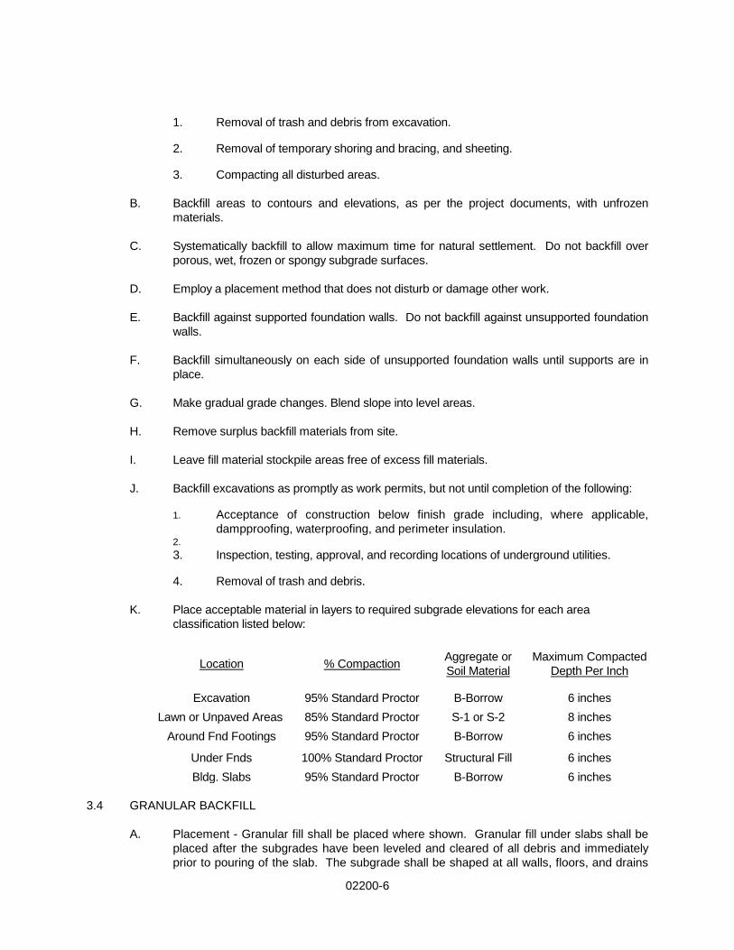
K. Place acceptable material in layers to required subgrade elevations for each area
classification listed below:
Location % Compaction Aggregate or Soil Material
Maximum Compacted Depth Per Inch
Excavation 95% Standard Proctor B-Borrow 6 inches Lawn or Unpaved Areas 85% Standard Proctor S-1 or S-2 8 inches
Around Fnd Footings 95% Standard Proctor B-Borrow 6 inches
Under Fnds 100% Standard Proctor Structural Fill 6 inches Bldg. Slabs 95% Standard Proctor B-Borrow 6 inches
3.4 GRANULAR BACKFILL
A. Placement - Granular fill shall be placed where shown. Granular fill under slabs shall be placed after the subgrades have been leveled and cleared of all debris and immediately prior to pouring of the slab. The subgrade shall be shaped at all walls, floors, and drains
02200-7
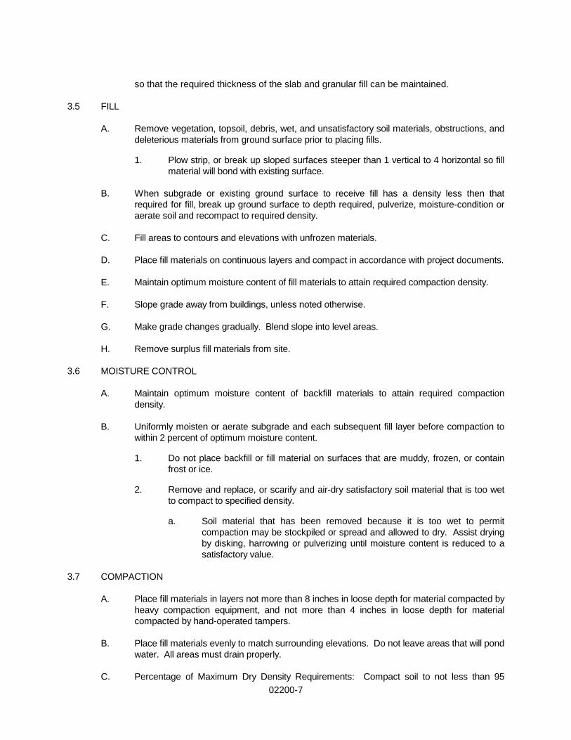
so that the required thickness of the slab and granular fill can be maintained. 3.5 FILL A. Remove vegetation, topsoil, debris, wet, and unsatisfactory soil materials, obstructions, and
deleterious materials from ground surface prior to placing fills. 1. Plow strip, or break up sloped surfaces steeper than 1 vertical to 4 horizontal so fill
material will bond with existing surface. B. When subgrade or existing ground surface to receive fill has a density less then that
required for fill, break up ground surface to depth required, pulverize, moisture-condition or aerate soil and recompact to required density.
C. Fill areas to contours and elevations with unfrozen materials. D. Place fill materials on continuous layers and compact in accordance with project documents.
E. Maintain optimum moisture content of fill materials to attain required compaction density.
F. Slope grade away from buildings, unless noted otherwise.
G. Make grade changes gradually. Blend slope into level areas.
H. Remove surplus fill materials from site.
3.6 MOISTURE CONTROL
A. Maintain optimum moisture content of backfill materials to attain required compaction density.
B. Uniformly moisten or aerate subgrade and each subsequent fill layer before compaction to
within 2 percent of optimum moisture content. 1. Do not place backfill or fill material on surfaces that are muddy, frozen, or contain
frost or ice. 2. Remove and replace, or scarify and air-dry satisfactory soil material that is too wet
to compact to specified density. a. Soil material that has been removed because it is too wet to permit
compaction may be stockpiled or spread and allowed to dry. Assist drying by disking, harrowing or pulverizing until moisture content is reduced to a satisfactory value.
3.7 COMPACTION A. Place fill materials in layers not more than 8 inches in loose depth for material compacted by
heavy compaction equipment, and not more than 4 inches in loose depth for material compacted by hand-operated tampers.
B. Place fill materials evenly to match surrounding elevations. Do not leave areas that will pond
water. All areas must drain properly.
C. Percentage of Maximum Dry Density Requirements: Compact soil to not less than 95

02200-8
percent of maximum dry density according to ASTM D 698. D. Granular material shall be placed in 6 inch loose layers and each layer compacted in
accordance with Section 02233 of the Specifications; the moisture content shall be not greater than 3 percentage points above optimum as determined by ASTM D698.
E. Embankments - Embankment fill shall be placed in 9 inch loose layers and each layer
compacted to not less than the percent of maximum dry density specified in Section 02233; the moisture content shall be not greater than 3 or less than one percentage points above optimum as determined by ASTM D698.
F. Subgrade - All roadway and parking area subgrades shall be compacted to a depth of 12
inches. Subgrade soils with a maximum dry density of less than 100 pounds per cubic foot are considered unsuitable for use where subgrade compaction for a depth of 12 inches is required, and when encountered in the upper 12 inches of the subgrade shall be replaced with suitable soil or granular material. Compaction shall be to a minimum density of 95% in accordance with ASTM D698.
G. Trenches for Pipe - Compaction of sewer pipe trenches shall be performed in accordance
with Section 02221. 3.8 STOCKPILING
A. Stockpile materials on site at locations indicated or as designated by Engineer. B. Stockpile in sufficient quantities to meet project schedule and requirements.
C. Separate differing materials with dividers or stockpile apart to prevent mixing.
D. Direct surface water away from stockpile site to prevent erosion or deterioration of materials.
3.9 STOCKPILE CLEANUP
A. Remove stockpile, leave area in a clean and neat condition. Grade site surface to prevent free standing surface water.
3.10 GRADING A. General: Uniformly grade areas to a smooth surface, free from irregular surface changes.
Comply with compaction requirements and grade to cross sections, lines, and elevations indicated.
1. Provide a smooth transition between existing adjacent grades and new grades. 2. Cut out soft spots, fill low spots, and trim high spots to conform to required surface
tolerances. B. Site Grading: Slope grades to direct water away as directed and to prevent ponding. Finish
subgrades to required elevations within the following tolerances: 1. All Areas: Plus or minus 0.10 foot.
C. Rough Grading - All areas shall be trimmed and graded to within 4 inches of the finished grades. These areas are to be free from rock or other foreign material, 3 inches or greater in dimension.

02200-9
D. Finished Grading - Topsoil shall be spread so as to conform to the finished grades.
3.11 FIELD QUALITY CONTROL A. Testing Agency Services: Allow testing agency to inspect and test each subgrade and each
fill layer. Do not proceed until test results for previously completed work verify compliance with requirements. Testing shall be in accordance with Section 02251.
B. When testing agency reports that subgrades, fills, or backfills are below specified density,
scarify and moisten or aerate, or remove and replace soil to the depth required, recompact and retest until required density is obtained.
C. Field inspection and testing will be performed under provisions of Section 01400.
Compaction testing will be conducted in accordance with ASTM 698. D. Provide for visual inspection of bearing surfaces.
E. Field density tests will be performed in sufficient number to insure that the specified
density is being obtained, but in no case shall less than one field density test for each 1,000 sq. ft. per foot of fill (one test per 1,000 SF of fill), one test at each structure at which fill or backfill is placed, and one test at existing subgrade prior to placement of fill. The specified testing is for the Owner only. Additional testing desired by the contractor shall be at not cost to the Owner.
F. If tests indicate materials and/or work do not meet specified requirements, the Contractor shall change materials or re-compact and re-test until the requirements are met at no additional cost to the Owner. Contractor shall coordinate and pay for all re-testing required.
3.12 PROTECTION
A. Protect excavations by methods required to prevent cave-in or loose soil from falling into excavation.
B. Protect bottom of excavations and soil adjacent to and beneath foundation, from freezing. C. Settling: Where settling occurs during the Project correction period, remove finished
surfacing, backfill with additional approved material, compact, and reconstruct surfacing. 1. Restore appearance, quality, and condition of finished surfacing to match adjacent
work, and eliminate evidence of restoration to the greatest extend possible. D. Protection Graded Areas: Protect newly graded areas from traffic and erosion. Keep free of
trash and debris. E. Repair and re-establish grades to specified tolerances where completed or partially
completed surfaces become eroded, rutted, settled, or loose compaction due to subsequent construction operations or weather conditions.
1. Scarify or remove and replace material to depth directed by the Engineer; reshape
and recompact at optimum moisture content to the required density.
F. Contractor shall control the grading around buildings or structures so that ground is pitched to prevent water from running into the excavated areas or damaging the structures. Maintain all pits and trenches where footings or structures are to be placed,

02200-10
free of water at all times.
G. Provide all pumping necessary to keep excavated spaces clear of water during construction. Should any springs or running water be encountered in the excavation, the Engineer shall be notified and the Contractor shall provide free discharge of it by trenches and drain to an appropriate point of disposal as directed.
H. Disposal of ground water for work below grade shall be the responsibility of the
Contractor. Water shall be directed to natural drains. Existing storm sewers may be used for disposal of this water so long as the sewer capacity is sufficient, and not during rain events.
3.13 DISPOSAL OF SURPLUS AND WASTE MATERIALS A. Disposal - All excavated material shall be disposed of as specified herein, unless
otherwise shown.
1. Acceptable as Fill Material
a. Excavation which is acceptable as fill material shall be used for backfill and embankments.
b. Surplus excavation which is acceptable as fill material shall be disposed
of off site, unless shown or directed otherwise.
2. Unacceptable as Fill Material - Excavation which is unacceptable as fill material shall be disposed of off site.
3.14 TOPSOIL A. Topsoil shall be stockpiled for reuse at the project site.
B. Place and final grade for seeding minimum of 4" of topsoil in all disturbed areas except building and paving areas.
3.15 TOLERANCES
A. Top Surface of Subgrade: Plus or minus 1/10 foot.
B. Top Surface of Backfilling Under Paved Areas: Plus or minus 1/4 inch from required elevations.
C. Top Surface of General Backfilling: Plus or minus 1/2 inch from required elevations.
3.16 SCHEDULES
A. As per the project documents.
END OF SECTION

02221-1
SECTION 02221
TRENCHING PART 1 GENERAL 1.1 SECTION INCLUDES
A. Excavating trenches. B. Compacted fill from top of utility bedding to subgrade elevations
C. Backfilling and compaction.
1.2 RELATED SECTIONS
A. Section 01400 – Quality Control B. Section 02200 – Earthwork
C. Section 02233 – Aggregate Materials
D. Section 03300 – Cast-in-Place Concrete: Concrete materials.
1.3 REFERENCES
A. ANSI/ASTM D698 – Test Methods for Moisture-Density Relations of Soils and Soil-Aggregate Mixtures, Using 5.5 lb (2.49 Kg) Rammer and 12 inch (304.8 mm) Drop.
1.4 DEFINITIONS
A. Utility: Any buried pipe, conduit, or cable or other improvement. 1.5 FIELD MEASUREMENTS
A. Verify that survey bench mark and intended elevations for the Work are as shown on drawing.
1.6 COORDINATION
A. Coordinate work under provisions as noted in the Division 01 specifications. B. Verify work associated with lower elevation utilities are complete before placing higher
elevation utilities. 1.7 EARTHWORK AND GRADING:
A. The trenching Contractor shall be responsible for leaving the site in a condition equal to that existing prior to trenching operations.
1.8 GENERAL TRENCHING
A. Trenches for pipes and other conduits shall be excavated of ample width to insure good workmanship in laying, jointing and backfilling. Unless otherwise permitted, all trenches in which mains are to be installed shall have a minimum width approximately twelve (12) inches wider than the inside diameter of the pipe being installed. Unless otherwise permitted, the

02221-2
maximum clear width of trench shall be not more than two (2) feet greater than the inside diameter of the pipe.
B. The trench shall have a flat bottom conforming to the grade to which the pipe is to be laid.
The pipe shall be laid upon prepared bottom as hereinafter specified, cut true and even so that the barrel of the pipe will have a bearing for its full length.
C. Care shall be taken not to injure the pipe or disturb its grade or alignment.
D. Material for backfilling shall be placed in the trenches in such a manner that no damage to
the pipe or joints will be possible. E. When bell and spigot pipe is to be used, bell holes of ample dimensions shall be dug at each
joint to permit the jointing to be properly made. F. When other type of pipe is used, such excavation as may be necessary to permit easy
jointing and to insure bedding of the pipe throughout its length shall be made. G. When bedding is required, it shall be so placed that the lower fourth of the pipe
circumference shall be firmly bedded therein. H. The work of backfilling and cleaning up shall proceed expeditiously so that the length of open
trench may be as short as possible. No trench may be opened more than 300 feet in advance of the completed work without the express permission of the Engineer.
I. The depth shall be sufficiently excavated to provide forty-eight inches (48”of cover between
the unfinished surface grade and the top of the pipe barrel or as specified on plans.
J. Excess excavated material not required for filling shall be removed at the Contractor's expense.
K. Trenches shall be cut as narrow as possible for installation of service lines and shall not
exceed eighteen (18”) inches in width unless rock excavation is required. L. Where the bottom of the trench at subgrade is found to be unstable or to include boulders
(less than 1/2 cubic yd. in volume) ashes, cinders, all types of refuse, vegetable or other organic material, or large pieces of fragments or inorganic material, which in the judgment of the Engineer should be removed, the Contractor shall excavate and remove such unsuitable material to a depth of not less than 4" and not more than 6" below the normal subgrade elevation. Before the pipe is laid, the subgrade shall provide a uniform and continuous bearing and support for the pipe at every point between the bell holes.
M. The Contractor shall excavate as necessary to perform the work and shall satisfactorily
remove and dispose of all rock and large boulders encountered in the excavation. N. Excavation of rock in or along highways shall be in accordance with the current regulations of
the Indiana Department of Transportation. Payment depth for rock excavation shall be the actual depth removed; however, it shall not exceed the pipe cover plus the pipes inside diameter plus 6".
1.9 BACKFILL PROCEDURE AT PIPE ZONE
A. Selected backfill material free from rock or debris shall be deposited simultaneously on both sides of the pipe in such a manner as to provide full bedding for the pipe as required on the drawings.

02221-3
1.10 BACKFILL PROCEDURE ABOVE PIPE ZONE
A. The pipe, unless otherwise permitted, shall be covered by hand to a depth of one foot (1’) and free of any piece of rock or stone larger than two inches (2”) in its largest dimension. The remainder of the trench may be backfilled with approved material, care being taken to exclude any piece of rock or stone larger than eight inches (8") in its largest dimension.
B. When the trench is within an area to be paved, including roadways, stone drives or country
roads, backfill shall be Special Trench Fill placed in even layers not exceeding eight inches (8") in depth before compaction and shall be thoroughly tamped. Granular materials may be compacted with vibratory tampers and just sufficient water to permit complete compaction. Mass jetting will not be permitted except by specific written approval of the Engineer.
C. Jetting or flooding may be permitted in trenches located outside of proposed paved areas, if
the backfill material is granular and air temperature is not less than 40 F. Pipe shall be water filled during the period of jetting and draining. Jetting method and conditions shall be approved by the Engineer.
D. When sheeting or bracing has been used, sufficient bracing shall be kept in place to prevent
caving or sliding during backfilling. This bracing shall be removed as backfilling progresses.
E. Backfill shall extend sufficiently above final grade, when practicable, to allow for final settlement. Any depressions, which may develop due to settlement of the backfill, shall be corrected by the Contractor at his expense during the 12 month period following acceptance of the work.
F. Surplus material shall be disposed of in a manner acceptable to the Engineer. G. The Engineer shall have authority to order trenches backfilled at any time in which his
judgment indicates that failure to backfill would result in damage or danger to structures, pavements, pipes, or to persons.
1.11 PUMPING AND DRAINAGE:
A. Under this Section shall be done all pumping, bailing and draining or otherwise disposing of any and all water or sewage, which may be encountered in connection with the work. Also all work shall be done which may be necessary to render the bottom of the excavation firm and dry and suitable for the laying of pipe or masonry thereon and to maintain such conditions for such period as may, in the opinion of the Engineer, be necessary.
B. Should any springs or running water be encountered in the excavation, the Engineer shall be
notified and the Contractor shall provide free discharge of it by trenches and drain to an appropriate point of disposal as directed.
C. Disposal of ground water for work below grade shall be the responsibility of the Contractor.
Water shall be directed to natural drains. Existing storm sewers may be used for disposal of this water so long as the sewer capacity is sufficient, and not during rain events.
1.12 PROTECTION OF EXCAVATION:
A. The Contractor shall furnish, put in place and maintain such sheeting, braces, caging and/or other devices, as may be required to support the sides of the excavation and to prevent any movement which could in any way injure or delay the work or endanger adjacent pavement, sewers, pipes, drains, conduits or other structure of the lives of workmen employed thereon.
B. Methods of sheeting and/or other protective devices shall be submitted to the Engineer for

02221-4
review. C. Trenches and other excavations, which do not require artificial support, shall be back-sloped
or benched as may be necessary to prevent movement or collapse. D. The Contractor shall have the sole responsibility of directing and conducting the work in a
manner which is in compliance with all pertinent regulations and accepted good practice and which will maintain a safe work area.
E. The Engineer may direct additional or improved bracing, sheeting, sloping or other changes
in work methods if, in the opinion of the Engineer, the methods used are unsafe. The Engineer may direct that work shall stop until such corrections have been made.
F. The right of the Engineer to order additional sheeting, bracing or slope cut shall not be
construed as creating an obligation on his part to issue such orders and his failure to exercise his right to do so shall not relieve the Contractor from liability for damages to persons or occasioned by negligence or otherwise, growing out of the failure of the Contractor to properly back slope, brace, sheet or otherwise protect the trench to prevent any caving or moving of the ground adjacent to the banks of the trench.
G. Remove shoring and boxes as the backfilling progresses, but only when banks are safe
against cave-ins or collapse, where shoring or underpinning furnishes permanent or temporary support, extreme care shall be taken to insure that no settlement or collapse will occur. Conform with OSHA safety rules and regulations.
H. Any voids left by the withdrawal of sheeting shall be carefully refilled with selected material
thoroughly rammed. PART 2 PRODUCTS 2.1 FILL MATERIALS
A. Granular Material, “B” Borrow: As specified in Section 02233, or approved equal, unless otherwise specified on the drawings.
2.2 SPECIAL TRENCH FILL
A. Special fill, where shown on the plans or required by the Engineer, shall be a predominantly granular material which can be readily compacted to a density which will produce no further settlement. Any material which meets the above requirements will ordinarily be acceptable; however, the selected material must be approved by the Engineer.
B. Special fill shall be compacted in uniform layers as outlined above in paragraphs 1 and 2
except that no post construction settlement will be acceptable. Compaction shall produce 98% of optimum density as determined by AASHTO T-99 (ASTM D-698).
PART 3 EXECUTION 3.1 PREPARATION
A. Identify required lines levels, contours, and datum. B. Protect plant life, lawns, rock outcropping and other features remaining as a portion of final
landscaping.

02221-5
C. Protect benchmarks, existing structures, fences, sidewalks, paving and curbs from excavation equipment and vehicular traffic.
D. Maintain and protect above and below grade utilities, which are to remain.
E. Cut out soft areas of subgrade not capable of in place compaction. Backfill with Fill Type #23
Sand and compact to density equal to or greater than requirements for subsequent backfill material.
3.2 EXCAVATION
A. Excavate as required for installation. B. Cut trenches sufficiently wide to enable installation and allow inspection.
C. Do not interfere with 45 degree bearing splay of foundation.
D. Hand trim excavation. Hand trim for bell and spigot pipe joints. Remove loose matter.
E. Remove lumped subsoil, boulders, and rock.
F. Correct areas over excavated in accordance with Section 02200.
G. Stockpile excavated material in area designated on site and remove excess material not
being used, from site. 3.3 BACKFILLING
A. Backfill trenches to contours and elevations with unfrozen materials per Section 02200. B. Systematically backfill to allow maximum time for natural settlement. Do not backfill over
porous, wet, frozen or spongy subgrade surfaces.
C. Employ a placement method that does not disturb or damage foundation perimeter drainage, conduit, or duct in trench.
D. Maintain optimum moisture content of fill materials to attain required compaction density.
E. Remove surplus fill materials from site.
F. Leave fill material stockpile areas completely free of excess fill materials.
3.4 TOLERANCES
A. Top Surface of Backfilling under Paved Areas: Plus or minus ¼ inch from required elevations.
B. Top Surface of General Backfilling: Plus or minus ½ inch from required elevations.
3.5 FIELD QUALITY CONTROL
A. Field inspection and testing will be performed under provisions as noted in the Division 01 specifications.
B. Compaction testing will be performed in accordance with ASTM D698.
C. Proof roll compacted fill surfaces.

02221-6
D. If tests indicate Work does not meet specified requirements, remove Work, replace, compact, and retest at no cost to the Owner.
E. The Contractor shall engage a Testing Laboratory.
1. The Testing Agency shall perform, to the Owner's satisfaction, the following tests
during progress of the work:
a. Gradation Test: Verify sample from supply source meets requirements of Indiana Department of Transportation for type of material specified.
b. In place density of subgrade: Verify in place of density of subgrade prior to
placement of fill, at locations per direction of Owner.
c. In place density of Compacted Fill & Backfill: Verify density of fill at locations, per direction of Owner.
F. Field density tests will be performed in sufficient number to insure that the specified density is being obtained, but in no case shall less than one field density test for each 1,000 sq. ft. per foot of fill (one test per 1,000 SF of fill), one test at each structure at which fill or backfill is placed, and one test at existing subgrade prior to placement of fill. The specified testing is for the Owner only. Additional testing desired by the contractor shall be at not cost to the Owner. 3.6 PROTECTION OF FINISHED WORK
A. Reshape and re-compact areas subjected to vehicular traffic during construction. 3.7 RESTORATION OF SURFACES, PAVEMENT, CURB, ETC.
A. All surface material, and curbing, sidewalks, gutters, shrubbery, fences and other surfaces disturbed, shall be restored to a condition equal to or better than that before the trenching began. In restoring paved surfaces, new pavement is required.
B. No permanent paving shall be placed above the trench within thirty (30) days after the
backfilling shall have been completed, except by order of the Engineer.
C. The Contractor shall furnish all labor and material incidental to such replacement. 3.8 SCHEDULE
A. As per project documents.
END OF SECTION

02233-1
SECTION 02233
AGGREGATE MATERIALS
PART 1 GENERAL 1.1 SECTION INCLUDES A. Aggregate Materials
B. Aggregate base for pavement. 1.2 RELATED SECTIONS
A. Section 01400 – Quality Control: Inspection of bearing surfaces
B. Section 02000 – Subsurface Exploration
C. Section 02221 – Trenching
D. Division 3 - Concrete 1.3 REFERENCES
A. AASHTO T99 - Moisture-Density Relations of Soils Using a 10-lb. Rammer and an 18-in. Drop.
B. ANSI/ASTM D698 - Test Methods for Moisture-Density Relations of Soils and Soil-Aggregate
Mixtures, Using 5.5 lb Rammer and 12 inch Drop.
C. ANSI/ASTM D698 - Test Methods for Moisture-Density Relations of Soils and Soil-Aggregate Mixtures Using 10 lb Rammer and 18 inch Drop.
D. ASTM D2167 - Test Method for Density and unit Weight of Soil in Place by the Rubber
Balloon Method.
E. ASTM D2922 - Test Methods for Density of Soil and Soil-Aggregate in Place by Nuclear Methods (Shallow Depth).
F. ASTM D3017 - Test Methods for Moisture Content of Soil and Soil-Aggregate Mixtures.
1.4 SUBMITTALS
A. Submit under provisions of Section 01300.
B. Materials Source: Submit name of imported materials supplies. Provide materials from same source throughout the work. Change of source requires Engineer approval.
PART 2 PRODUCTS 2.1 AGGREGATE MATERIALS
A. Structural Fill, Type #53: Conforming to Indiana Department of Transportation Standard Specification, Latest Edition.

02233-2
B. Backfill, “B” Borrow: Conforming to Indiana Department of Transportation Standard Specification, Latest Edition.
A. Coarse Aggregate Fill: #53 Crushed Limestone
2.2 SOURCE QUALITY CONTROL
A. Field inspection and testing will be performed under provisions of Section 01400. B. The Contractor shall employ a Testing Agency and the Testing Agency shall:
1. Perform the following tests during progress of the work:
a. Gradation Test: Verify samples from supply source meets requirements of
Indiana Department of Transportation for the type of material specified.
b. In place density of Subgrades: Verify in place density of subgrade prior to placement of fill at locations per direction of Owner/Engineer.
c. In place density of compacted fill and backfill: Verify density of fill at locations per direction of Engineer.
PART 3 EXECUTION 3.1 EXAMINATION
A. Verify substrate has been inspected, gradients and elevations are correct, and dry. 3.2 STOCKPILING
A. Stockpile materials on site at locations indicated or as designated by Engineer. B. Stockpile in sufficient quantities or arrange for the delivery of materials as needed to meet
project schedule and requirements. C. Separate differing materials with dividers or stockpile apart to prevent mixing.
D. Direct surface water away from stockpile site so as to prevent erosion or deterioration of
materials. 3.3 STOCKPILE CLEANUP
A. Remove stockpile, leave area in a clean and neat condition. Grade site surface to prevent free standing surface water.
B. If a borrow area is indicated, leave area in a clean and neat condition. Grade site surface to
prevent free standing surface water. 3.4 SCHEDULE
A. As per project documents. 3.5 AGGREGATE PLACEMENT
A. Proof roll subgrade with 25 ton roller as per Indiana Department of Transportation Specifications, Latest Edition.

02233-3
B. Spread aggregate over prepared substrate to a total compacted thickness as shown on the drawings.
C. Place aggregate in maximum 6 inch layers and roller compact.
D. Level and contour surfaces to elevations and gradients indicated.
E. Use mechanical tamping equipment in areas inaccessible to compaction equipment.
3.6 TOLERANCES
A. Flatness: Maximum variation of 2 inch measured with 10 foot (3 m) straight edge.
B. Scheduled Compacted Thickness: Within 2 inch.
C. Variation from True Elevation: Within 2 inch. 3.7 FIELD QUALITY CONTROL
A. Field inspection and testing will be performed under provisions of Section 01400.
B. Compaction testing will be performed in accordance with ASTM D698.
C. If tests indicate Work does not meet specified requirements, remove Work, replace and retest at no cost to the Owner.
D. Frequency of Tests: Per INDOT Standard Specifications and Testing Frequency Manual.
END OF SECTION


02251-1
SECTION 02251 MATERIALS TESTING PART 1 GENERAL 1.1 SECTION INCLUDES A. Testing by Contractor’s testing agency. B. Testing of backfilled areas where buildings, structures, and utilities were located. C. Reports by testing agencies. 1.2 SUBMITTALS A. Submit under the provisions of Section 01300. B. Test Reports: Testing Agency shall provide the following directly to the Engineer with copy
to Contractor. 1. Reports summarizing the results of bearing tests of each stratum tested. 1.3 QUALITY ASSURANCE A. Codes and Standards: Perform testing in compliance with requirements of authorities
having jurisdiction. B. Contractor shall employ a qualified independent geotechnical engineering testing agency to
perform required field and laboratory testing to verify that completed work is in conformance with project plans and specifications.
C. Contractor shall cooperate and work with Testing Agent in order to accomplish the testing
required. D. It shall be the Contractor's responsibility to notify Testing Agent 24 hours in advance of
required testing, and also to notify Testing Agent of cancellations to eliminate unnecessary trips.
E. If testing is not performed as required, Contractor shall be responsible for re-excavating and
re-compacting as required for testing to be performed at no additional expense to the Owner.
PART 2 PRODUCTS - NOT USED PART 3 EXECUTION 3.1 TESTING AGENCY SERVICES A. Testing Agency shall complete the following: 1. Perform field in-place density tests in accordance with this specification.
02251-2
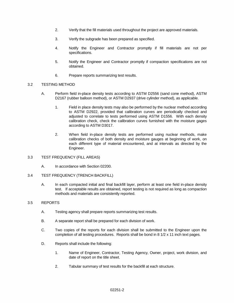
2. Verify that the fill materials used throughout the project are approved materials. 3. Verify the subgrade has been prepared as specified. 4. Notify the Engineer and Contractor promptly if fill materials are not per
specifications. 5. Notify the Engineer and Contractor promptly if compaction specifications are not
obtained. 6. Prepare reports summarizing test results. 3.2 TESTING METHOD
A. Perform field in-place density tests according to ASTM D2556 (sand cone method), ASTM D2167 (rubber balloon method), or ASTM D2937 (drive cylinder method), as applicable.
1. Field in place density tests may also be performed by the nuclear method according
to ASTM D2922, provided that calibration curves are periodically checked and adjusted to correlate to tests performed using ASTM D1556. With each density calibration check, check the calibration curves furnished with the moisture gages according to ASTM D3017.
2. When field in-place density tests are performed using nuclear methods, make
calibration checks of both density and moisture gauges at beginning of work, on each different type of material encountered, and at intervals as directed by the Engineer.
3.3 TEST FREQUENCY (FILL AREAS)
A. In accordance with Section 02200.
3.4 TEST FREQUENCY (TRENCH BACKFILL)
A. In each compacted initial and final backfill layer, perform at least one field in-place density test. If acceptable results are obtained, report testing is not required as long as compaction methods and materials are consistently reported.
3.5 REPORTS A. Testing agency shall prepare reports summarizing test results. B. A separate report shall be prepared for each division of work. C. Two copies of the reports for each division shall be submitted to the Engineer upon the
completion of all testing procedures. Reports shall be bond in 8 1/2 x 11 inch text pages. D. Reports shall include the following:
1. Name of Engineer, Contractor, Testing Agency, Owner, project, work division, and date of report on the title sheet.
2. Tabular summary of test results for the backfill at each structure.

02251-3
3. Letter from the testing agency, which certifies that material tested were found to be in compliance with the project documents.
END OF SECTION


02270-1
SECTION 02270
EROSION CONTROL PART 1 GENERAL 1.1 DESCRIPTION
A. All erosion and sediment control measures shown on the plans and referenced in this specification shall meet the design criteria, standards and specifications outlined in the latest edition of the “Indiana Storm Water Quality Manual” from the Indiana Department of Environmental Management.
1.2 RELATED SECTIONS
A. Section 02936 - Seeding
1.3 GUIDELINES A. The Contractor shall include in his bid costs for the installation of all necessary erosion
control items. It is the Contractor’s responsibility that all design criteria, standards and specifications are met and that all land disturbing activities are in accordance with the erosion/sediment control plan.
B. The Contractor shall retain existing vegetation on the construction site wherever possible.
If existing vegetation must be cleared, retain and protect it until the area must be disturbed.
C. The Contractor shall maintain a buffer strip of existing vegetation around the perimeter of
the site to reduce off-site erosion and sedimentation.
D. The Contractor shall minimize the extent and duration that bare soil is exposed to erosion by wind and water. Use staged clearing and grading to reduce the amount of disturbed area to the absolute minimum needed for immediate construction activities.
E. The Contractor shall keep sediment on the construction site as much as possible. Retain
sediment from unavoidable erosion on-site by trapping it with sediment basins or filtering it out of runoff with vegetative or man-made barriers. The Contractor shall install any needed sediment traps and basin before construction activity begins.
F. The Contractor shall divert off-site runoff away from disturbed areas, if possible. The
installation of these measures shall take place prior to clearing and grading to reduce the potential for erosion.
G. The Contractor shall stabilize disturbed areas as soon as possible. Stabilizing measures,
such as seeding temporary or permanent vegetation, sodding, mulching, sediment basins, erosion control blankets, or other protective practices shall be installed within seven days after the land has been disturbed.
H. The Contractor shall keep velocity of runoff leaving the site low.
I. The Contractor shall install drain inlet protection as soon as the storm sewer system is
functional.

02270-2
J. The Contractor shall assign someone the responsibility for routine, end-of-day inspection/maintenance checks of all erosion and sediment control measures. All measures shall be inspected for damage after each storm event. Damaged measures shall be repaired immediately.
K. The Contractor shall remove the interim measure when all areas protected are stabilized.
The Contractor shall then establish permanent stabilization protection before the entire site may be considered permanently stabilized.
L. The Contractor shall be responsible for the maintenance, repair, and/or replacement of all
required control measures with all disturbed areas being stabilized to the satisfaction of the local SWCD, County Surveyor, Owner, or Engineer.
PART 2 MEASURES 2.1 Refer to the erosion control plan for type and location of measures to be installed. 2.2 Temporary Seeding. A. Requirements
1. Site and Seedbed Preparation
2. Plant Species
Seed Species Rate / Acre Planting Depth Optimum Dates
Wheat or Rye 150 pounds 1 to 1.5 inches 9/15 to 10/30 Spring Oats 100 pounds 1 inch 3/1 to 4/15
Annual Ryegrass 40 pounds ¼ inch 3/1 to 5/1 8/1 to 9/1
German Millet 40 pounds 1 to 2 inches 5/1 to 6/1 Sudangrass 35 pounds 1 to 2 inches 5/1 to 7/30
3. Mulch
a. Clean grain straw, hay, wood fiber, etc., to protect seedbed and encourage plant growth.
b. From November 1 to March 1, mulching alone shall be used to stabilize
disturbed areas.
4. Seeding Frequency. Seed as often as possible following construction activity. Daily seeding of rough graded areas when the soil is loose and moist is usually most effective.
2.3 Dust Control
A. Road Surfaces: Apply calcium chloride, as needed, at a rate that will keep surface moist.
B. Street Cleaning: Brush, sweep or scoop street. Do not flush unless flow can be directed into an inlet, sediment trap or basin.

02270-3
PART 3 INSTALLATION 3.1 Refer to the “Indiana Storm Water Quality Manual”, latest edition for installation instructions for
the measures shown on the erosion control plan. 3.2 Temporary Seeding
A. Site Preparation
1. Install practices needed to control erosion, sedimentation, and water runoff, such s temporary and permanent diversions, sediment traps or basins, silt fences, and straw bale dams.
2. Grade the site as specified in the construction plans.
B. Seedbed Preparation
1. Fertilize by applying 18 pounds / 1000 square feet of 12-12-12 analysis, or equivalent, fertilizer.
2. Work the fertilizer into the soil 2-4 inches deep with a disk or rake operated
across the slope.
C. Seeding
1. Select a seeding mixture and rate from Section 2.2 and plant at depth and on dates shown.
2. Apply seed uniformly with a drill or cultipacker-seeder or by broadcasting and
cover to the depth shown in Section 2.2.
3. If drilling or broadcasting, firm the seedbed with a roller or cultipacker.
4. Mulch seeded areas to increase seeding success. Anchor all mulch by crimping or tackifying. Use of netting or erosion control blankets is possible, but may not be cost effective for temporary seeding.
3.3 Dust Control
A. Apply as needed to prevent wind-borne dust, which could create a health and/or visibility
hazard downwind, from leaving the construction area.
END OF SECTION


02600 - 1
SECTION 02600
FENCES AND GATES PART 1 GENERAL 1.1 SUMMARY A. This Section includes the following: 1. Fence framework and fabric. 2. Gates 1.2 SUBMITTALS A. Product data in the form of manufacturer's technical data, specifications, and installation
instructions for fence and gate posts, fabric, gates, gate operators, and accessories. B. Shop drawings showing location of fence, gates, each post, and details of post
installation, extension arms, gate swing, hardware, and accessories. 1.3 QUALITY ASSURANCE A. Installer Qualifications: Engage an experienced Installer who has at least three years'
experience and has completed at least five chain link fence projects with same material and of similar scope to that indicated for this Project with a successful construction record of in-service performance.
B. Single-Source Responsibility: Obtain chain link fences and gates, including accessories,
fittings, and fastenings, from a single source. 1.4 PROJECT CONDITIONS A. Field Measurements: Verify layout information for fences and gates shown on the
Drawings in relation to the property survey and existing structures. Verify dimensions by field measurements.
1.5 REFERENCES
A. American Society for Testing and Materials (ASTM), Fifth edition. B. A 446 (1987) Standard Specification for Steel Sheet, Zinc Coated (Galvanized) by the
Hot-Dip Process, Structural (physical) Quality. C. A500 (1993) Standard Specification for Cold formed welded and seamless carbon
steel structural tubing in round shapes. D. A 641 (1989) Standard Specification for Zinc-Coated (Galvanized) Carbon Steel Wire. E. B 6 (1987) Standard Specification for Zinc F. B 117 (1990) Standard Test Method of Salt Spray (Fog) Testing.
02600 - 2
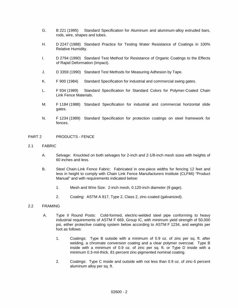
G. B 221 (1995) Standard Specification for Aluminum and aluminum-alloy extruded bars, rods, wire, shapes and tubes.
H. D 2247 (1988) Standard Practice for Testing Water Resistance of Coatings in 100%
Relative Humidity. I. D 2794 (1990) Standard Test Method for Resistance of Organic Coatings to the Effects
of Rapid Deformation (Impact). J. D 3359 (1990) Standard Test Methods for Measuring Adhesion by Tape. K. F 900 (1984) Standard Specification for industrial and commercial swing gates. L. F 934 (1989) Standard Specification for Standard Colors for Polymer-Coated Chain
Link Fence Materials. M. F 1184 (1988) Standard Specification for industrial and commercial horizontal slide
gates. N. F 1234 (1989) Standard Specification for protection coatings on steel framework for
fences. PART 2 PRODUCTS - FENCE 2.1 FABRIC A. Selvage: Knuckled on both selvages for 2-inch and 2-1/8-inch mesh sizes with heights of
60 inches and less. B. Steel Chain-Link Fence Fabric: Fabricated in one-piece widths for fencing 12 feet and
less in height to comply with Chain Link Fence Manufacturers Institute (CLFMI) "Product Manual" and with requirements indicated below:
1. Mesh and Wire Size: 2-inch mesh, 0.120-inch diameter (9 gage). 2. Coating: ASTM A 817, Type 2, Class 2, zinc-coated (galvanized). 2.2 FRAMING A. Type II Round Posts: Cold-formed, electric-welded steel pipe conforming to heavy
industrial requirements of ASTM F 669, Group IC, with minimum yield strength of 50,000 psi, either protective coating system below according to ASTM F 1234, and weights per foot as follows:
1. Coatings: Type B outside with a minimum of 0.9 oz. of zinc per sq. ft. after
welding, a chromate conversion coating and a clear polymer overcoat. Type B inside with a minimum of 0.9 oz. of zinc per sq. ft. or Type D inside with a minimum 0.3-mil-thick, 81-percent zinc-pigmented nominal coating.
2. Coatings: Type C inside and outside with not less than 0.9 oz. of zinc-5 percent
aluminum alloy per sq. ft.

02600 - 3
Actual OD Weight (lb/ft) NPS Size 1.315 1.35 1 1.660 1.84 1-1/4 1.900 2.28 1-1/2 2.375 3.12 2 2.875 4.64 2-1/2 3.500 5.71 3 4.000 6.56 3-1/2
B. Top Rail: Manufacturer's longest lengths (17 to 21 feet) with swedged-end or expansion-type coupling, approximately 6 inches long for joining. Provide rail ends or other means for attaching top rail securely to each gate corner, pull, and end post.
1. Round Steel: 1.660-inch OD Type II steel pipe.
C. Steel posts for fabric heights up to 6 feet:
1. Round Line or Intermediate Posts: 1.90-inch OD Type II steel pipe. 2. Round End, Corner, and Pull Posts: 2.375-inch OD Type II steel pipe.
D. Swing Gate Posts: Furnish posts to support single gate leaf, or one leaf of a double-gate
installation, according to ASTM F 900, sized as follows for steel and aluminum pipe posts:
1. Steel posts for fabric height of 6 feet or less and gate leaf width: a. Over 4 to 10 Feet: 2.875-inch OD pipe weighing at least 4.64 lb per ft.
E. Opening Width Up to 12 feet: 2.875-inch OD pipe weighing not less than 4.64 lb per ft. 2.3 FITTINGS AND ACCESSORIES A. Material: Comply with ASTM F 626. Mill-finished galvanized steel to suit manufacturer's
standards. 1. Steel: Unless specified otherwise, hot-dip galvanize pressed steel or cast-iron
fence fittings and accessories with at least 1.2 oz. zinc per sq. ft. as determined by ASTM A 90.
B. Post and Line Caps: Provide weathertight closure cap for each post. Provide line post
caps with loop to receive tension wire or top rail. C. Post Brace Assembly: Manufacturer's standard adjustable brace. Use material specified
below for brace, and truss to line posts with 3/8-inch-diameter rod and adjustable tightener. Provide manufacturer's standard galvanized-steel, cast-iron or cast-aluminum cap for each end.
1. Round Steel: 1.660-inch OD Type II steel pipe. D. Bottom and Center Rail: Same material as top rail. Provide manufacturer's standard
galvanized-steel and two for each corner and pull post, except where fabric is integrally woven into the post.
E. Tension and Brace Bands: 3/4-inch-wide minimum hot-dip galvanized steel with a

02600 - 4
minimum of 1.2 oz. of zinc coating per sq. ft. 1. Tension Bands: 0.074 inch thick (14 gage) minimum. 2. Brace Bands: 0.105 inch thick (12 gage) minimum cap for each end. F. Tension or Stretcher Bars: Hot-dip galvanized steel with a minimum length 2 inches less
than the full height of fabric, a minimum cross section of 3/16 inch by 3/4 inch, and a minimum of 1.2 oz. of zinc coating per sq. ft. Provide one bar for each gate and end post,
G. Tension Wire: 0.177-inch-diameter metallic-coated steel marcelled tension wire
conforming to ASTM A 824 with finish to match fabric. 1. Coating Type II zinc in the following class as determined by ASTM A 90. a. Class 2, with a minimum coating weight of 1.20 oz. per sq. ft. of uncoated
wire surface. H. Tie Wires: 0.106-inch-diameter (12-gage) galvanized steel with a minimum of 0.80 oz.
per sq. ft. of zinc coating according to ASTM A 641, Class 3 or 0.148-inch-diameter (9-gage) aluminum wire alloy 1350-H19 or equal, to match fabric wire.
2.4 CONCRETE A. Concrete: Provide concrete consisting of portland cement per ASTM C 150, aggregates
per ASTM C 33, and potable water. Mix materials to obtain concrete with a minimum 28-day compressive strength of 4000 psi. Use at least four sacks of cement per cu. yd., 1-inch maximum size aggregate, 3-inch maximum slump.
B. Packaged Concrete Mix: Mix dry-packaged normal-weight concrete conforming to ASTM
C 387 with clean water to obtain a 2- to 3-inch slump. PART 3 PRODUCTS - GATES 3.1 SWING GATES - Not Applicable 3.2 CANTILIVER SLIDE GATE – Not Applicable 3.3 SLIDING GATE – Not Applicable PART 4 EXECUTION 2.1 FENCE INSTALLATION A. Install fence to comply with ASTM F 567. Do not begin installation and erection before
final grading is completed, unless otherwise permitted. B. Excavation: Drill or hand-excavate (using post-hole digger) holes for posts to diameters
and spacing indicated, in firm, undisturbed or compacted soil. 1. If not indicated on Drawings, excavate holes for each post to minimum diameter
recommended by fence manufacturer, but not less than four times the largest cross section of post.
02600 - 5
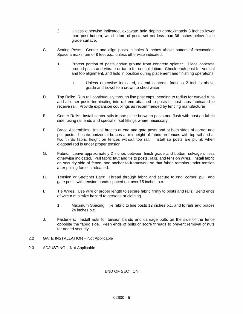
2. Unless otherwise indicated, excavate hole depths approximately 3 inches lower than post bottom, with bottom of posts set not less than 36 inches below finish grade surface.
C. Setting Posts: Center and align posts in holes 3 inches above bottom of excavation.
Space a maximum of 8 feet o.c., unless otherwise indicated. 1. Protect portion of posts above ground from concrete splatter. Place concrete
around posts and vibrate or tamp for consolidation. Check each post for vertical and top alignment, and hold in position during placement and finishing operations.
a. Unless otherwise indicated, extend concrete footings 2 inches above
grade and trowel to a crown to shed water. D. Top Rails: Run rail continuously through line post caps, bending to radius for curved runs
and at other posts terminating into rail end attached to posts or post caps fabricated to receive rail. Provide expansion couplings as recommended by fencing manufacturer.
E. Center Rails: Install center rails in one piece between posts and flush with post on fabric
side, using rail ends and special offset fittings where necessary. F. Brace Assemblies: Install braces at end and gate posts and at both sides of corner and
pull posts. Locate horizontal braces at midheight of fabric on fences with top rail and at two thirds fabric height on fences without top rail. Install so posts are plumb when diagonal rod is under proper tension.
G. Fabric: Leave approximately 2 inches between finish grade and bottom selvage unless
otherwise indicated. Pull fabric taut and tie to posts, rails, and tension wires. Install fabric on security side of fence, and anchor to framework so that fabric remains under tension after pulling force is released.
H. Tension or Stretcher Bars: Thread through fabric and secure to end, corner, pull, and
gate posts with tension bands spaced not over 15 inches o.c. I. Tie Wires: Use wire of proper length to secure fabric firmly to posts and rails. Bend ends
of wire o minimize hazard to persons or clothing. 1. Maximum Spacing: Tie fabric to line posts 12 inches o.c. and to rails and braces
24 inches o.c. J. Fasteners: Install nuts for tension bands and carriage bolts on the side of the fence
opposite the fabric side. Peen ends of bolts or score threads to prevent removal of nuts for added security.
2.2 GATE INSTALLATION – Not Applicable 2.3 ADJUSTING – Not Applicable END OF SECTION


02605-1
SECTION 02605
PRECAST MANHOLES
PART 1 GENERAL 1.1 DESCRIPTION
A. Furnish labor materials, tools and equipment for the installation of precast manholes, including valve vaults and lift station wet wells. For this project the Contractor shall provide precast structure base sections per the details shown in the plans.
1.2 WORK INCLUDED
A. Excavation and backfill B. Precast Manhole sections D. Frames and covers
E. Manhole steps F. Pipe seals
1.3 RELATED WORK
A. 02200 - Earthwork 1.4 REGULATORY REQUIREMENTS A. All work and materials shall conform to the latest addition of Indiana Department of Transportation Standards, at time of construction. PART 2 PRODUCTS 2.1 PRECAST CONCRETE SECTIONS
A. Precast concrete sections and appurtenances shall conform to the ASTM Standard Specifications for Precast Reinforced Concrete Manhole Sections. Designation C479-78, with the following exceptions and additional requirements:
B. The wall sections shall be not less than 5 inches thick. C. Joints between sections shall be made with round (O-ring) rubber gaskets with a suitable
groove on the spigot ends and shall conform to the ASTM Standard Specifications for Joints for Circular Concrete Sewer and Culvert Pipe, Using Rubber Gaskets, Designation C443-79. In addition to the O-Ring gasket the Contractor shall seal all manhole joints with mastic as directed by the Engineer.
2.2 PREMOLDED ELASTOMERIC-SEALED JOINTS
A. The Contractor shall use premolded elastomeric-sealed joints for pipe into precast manhole bases as indicated and as specified.
B. Premolded elastomeric-sealed joints shall be Lock Joint Flexible Manhole Sleeve made by Interpace Corp., Parsippany, NJ; Kor-N-Seal made by National Pollution Control Systems,

02605-2
Inc., Nashua, NH; Press Wedge II made by Press-Seal Gasket Corp., Fort Wayne, IN; A-Lok Manhole Pipe Seal made by A-Lok Corp., Trenton, NJ; or an acceptable equivalent product.
C. All materials, accessories and construction methods used in making the joint shall be
supplied, or approved by the manufacturer of the premolded elastomeric-sealed joint.
D. The Contractor shall furnish the manufacturer’s written instructions for installation prior to such installation.
E. Openings for pipe and materials to be embedded in the wall of the base for these joints shall
be cast in the base of the required locations during the manufacture of the base. 2.3 Access Hatches
A. Access hatches shall be aluminum with fall protection safety grating as indicated on the drawings.
2.4 STEPS
A. Manhole steps shall be copolymer polypropylene plastic type with ½" grade 60 steel reinforcement and shall meet the requirements of ASTM C-478, Section 11. The step shall be M.A. Industries PS-1, or equal.
B. The distance between the top of casting and the first step shall be not more than 24" and all
other steps spaced at 16” apart. Precast sections shall be sized so that there spacing requirements can be met.
2.5 MATERIALS FOR LEAK REPAIRS AT MANHOLES
A. The Contractor shall seal leaks at manholes using AV-118 Duriflex acrylic resin chemical grout as manufactured by Avanti International of Webster, TX, or acceptable equivalent.
B. Holes drilled to inject the chemical grout shall be plugged with Octocrete dry polymer
modified repair mortar as manufactured by IPA Systems, Inc., Philadelphia, PA, or acceptable equivalent.
C. The Contractor shall repair the surface of each application with Drycon waterproofing as
manufactured by IPA Systems, Inc., Philadelphia, PA, or acceptable equivalent. PART 3 EXECUTION 3.1 INSTALLATION
A. Manhole sections shall contain manhole steps accurately positioned and embedded in the concrete.
B. Sections shall be cured by subjecting them to thoroughly saturated steam at a temperature
between 100 and 130 degrees F. For a period of not less than 12 hours or, when necessary for such additional time as may be needed to enable the sections to meet the strength requirements. Sections shall not be shipped from the point of manufacture for at least 5 days from the casting date.
C. No more than two lift holes may be cast or drilled inside each section. Lift holes will not be
permitted to penetrate through the outside of the sections.

02605-3
D. The date of manufacture and the name or trademark of the manufacturer shall be clearly marked on the inside of the barrel.
E. Acceptance of the sections will be on the basis of material tests and inspection of the
completed product. G. The tops of the bases shall be suitably shaped by means of accurate bell-ring forms to
receive the barrel sections. H. Excavating for manholes shall be of sufficient size to adequately accommodated installation
and proper centering and for compacting backfill. 3.2 SETTING PRECAST MANHOLE SECTIONS
A. Precast-reinforced concrete manhole sections shall be set vertical and with sections and steps in true alignment.
B. Rubber gaskets shall be installed in all joints in accordance with the manufacturer’s
recommendations.
C. All holes in sections used for their handling shall be thoroughly plugged with rubber plugs made specifically for this purpose or with mortar. The mortar shall be one part cement to 1-1/2 parts sand, mixed slightly damp to the touch (just short of “balling”), hammered into the holes until it is dense and an excess of paste appears on the surface, and then finished smooth and flush with the adjoining surfaces.
3.3 SETTING HATCHES
A. Access hatch frames shall be cast into the concrete lid, inc accordance with manufacturer specifications.
3.4 MANHOLE REPAIR
A. The Contractor shall drill holes in the manhole wall where leaks may occur. The Duriflex
grout shall be injected through the hole until the leak stops. The contractor shall then fill the hole with the Octocrete and coat the surface with Dryon. All application of materials shall be in accordance with the manufacturer’s recommended procedures.
3.5 TESTING
A. Visual Test – Each manhole shall be visually inspected after assembly for deformities and potential leakage.
B. Vacuum Test – Vacuum testing of each manhole by means of negative air pressure per
ASTM C1244-93 shall be required.
1. Summary of Practice
a. All lift holes and any pipes entering the manhole are to be plugged. A vacuum will be drawn and the vacuum drop over a specified time period is used to determine the acceptability of the manhole.
2. Preparation of the Manhole
a. All lift holes shall be plugged b. All pipes entering the manhole shall be temporarily plugged, taking care to

02605-4
securely brace the pipes and plugs to prevent them from being drawn into the manhole.
3. Procedure
a. The test head shall be placed at the top of the manhole in accordance with
the manufacturer’s recommendations. Testing also includes the casting and any adjusting rings.
b. A vacuum of 10 in. of mercury shall be drawn on the manhole, the valve on
the vacuum line of the test head closed and the vacuum pump shut off. The time shall be measured for the vacuum to drop to 9 in. of mercury.
c. The manhole shall pass if the time for the vacuum reading to drop from 10
in. of mercury to 9 in. of mercury meets or exceeds the values indicated in Table 1.
d. If the manhole fails the initial test, necessary repairs shall be made by an
approved method. The manhole shall then be retested until a satisfactory test is obtained.
Minimum Test Times for Various Manhole Diameters
Depth Diameter (in.) / Time (sec.)
(ft.) 30 33 36 42 48 54 60 66 72 8 11 12 14 17 20 23 26 29 33 10 14 15 18 21 25 29 33 36 41 12 17 18 21 25 30 35 39 43 49 14 20 21 25 30 35 41 46 51 57 16 22 24 39 34 40 46 52 58 67 18 25 27 32 38 45 52 59 65 73 20 28 30 35 42 50 53 65 72 81 22 31 33 39 46 55 64 72 79 89 24 33 36 42 51 59 64 78 87 97 26 36 39 46 55 64 75 85 94 105 28 39 42 49 59 69 81 91 101 113 30 42 45 53 63 74 87 98 108 121
END OF SECTION

02700-1
SECTION 02700
POLYETHYLENE GEOMEMBRANE LINER PART 1 GENERAL 1.1 SECTION INCLUDES
A. Specifications and guidelines for MANUFACTURING and INSTALLING geomembrane. 1.2 REFERENCES
A. American Society for Testing and Materials (ASTM)
1. D 638 Standard Test Method for Tensile Properties of Plastics 2. D 1004 Test Method for Initial Tear Resistance of Plastic Film and Sheeting 3. D 1238 Standard Test Method for Flow Rates of Thermoplastics by Extrusion
Plastometer 4. D 1505 Test Method for Density of Plastics by the Density-Gradient Technique 5. D 1603 Test Method for Carbon Black in Olefin Plastics 6. D 3895 Standard Test Method for Oxidative-Induction Time of Polyolefins by
Differential Scanning Calorimetry 7. D 4833 Standard Test Method for Index Puncture Resistance of Geotextiles,
Geomembranes, and Related Products 8. D 5199 Standard Test Method for Measuring Nominal Thickness of Geotextiles
and Geomembranes 9. D 5397 Standard Test Method for Evaluation of Stress Crack Resistance of
Polyolefin Geomembranes Using Notched Constant Tensile Load Test 10. D 5596 Standard Test Method for Microscopic Evaluation of the Dispersion of
Carbon Black in Polyolefin Geosynthetics 11. D 5994 Standard Test Method for Measuring Core Thickness of Textured
Geomembranes 12. D 6392 Standard Test Method for Determining the Integrity of Non-reinforced
Geomembrane Seams Produced Using Thermo-Fusion Methods
1.3 DEFINITIONS
A. Lot- A quantity if resin (usually the capacity of one rail car) used in the manufacture of polyethylene geomembrane rolls. The finished roll will be identified by a roll number traceable to the resin lot used.
B. Construction Quality Assurance Consultant (CONSULTANT)- Party, independent from
MANUFACTURER and INSTALLER that is responsible for observing and documenting activities related to quality assurance during the lining system construction.

02700-2
C. ENGINEER- The individual or firm responsible for the design and preparation of the project’s Contract Drawings and Specifications. D. Geomembrane Manufacturer (MANUFACTURER)- The party responsible for
manufacturing the geomembrane rolls. E. Geosynthetic Quality Assurance Laboratory (TESTING LABORATORY)- Party,
independent from the OWNER, MANUFACTURER and INSTALLER, responsible for conducting laboratory tests on samples of geosynthetics obtained at the site or during manufacturing, usually under the direction of the OWNER.
F. INSTALLER- Party responsible for field handling, transporting, storing, deploying,
seaming and testing of the geomembrane seams. G. Panel - Unit area of a geomembrane that will be seamed in the field that is larger than 100
square feet. H. Patch - Unit area of a geomembrane that will be seamed in the field that is less than 100 square feet. I. Subgrade Surface - Soil layer surface which immediately underlies the geosynthetic material(s).
1.4 SUBMITTALS POST- AWARD A. Furnish the following product data, in writing, to ENGINEER prior to installation
of the geomembrane material:
1. Resin Data shall include the following.
a. Certification stating that the resin meets the specification requirements (see Section 1.9).
2. Geomembrane Roll
a. Statement certifying no reclaimed polymer is added to the resin (product
run may be recycled).
B. The INSTALLER shall furnish the following information to the ENGINEER and OWNER prior to installation:
1. Installation layout drawings
a. Must show proposed panel layout including field seams and details b. Must be approved prior to installing the geomembrane
1) Approved drawings will be for concept only and actual panel placement will be determined by site conditions.
2. Installer’s Geosynthetic Field Installation Quality Assurance Plan
02700-3
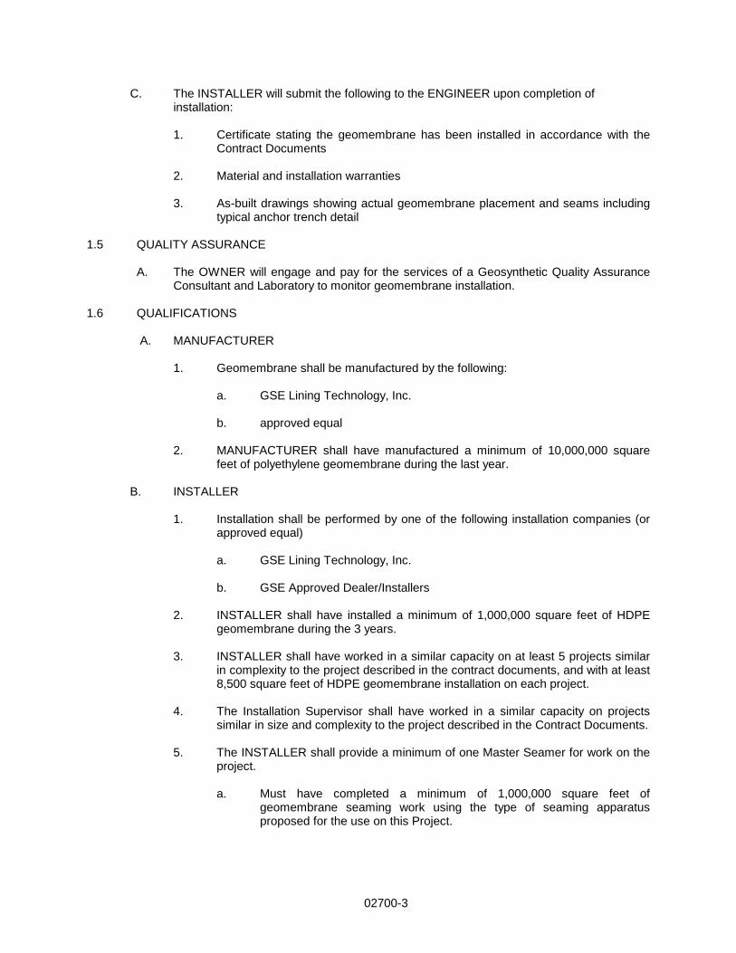
C. The INSTALLER will submit the following to the ENGINEER upon completion of installation:
1. Certificate stating the geomembrane has been installed in accordance with the Contract Documents
2. Material and installation warranties
3. As-built drawings showing actual geomembrane placement and seams including
typical anchor trench detail 1.5 QUALITY ASSURANCE
A. The OWNER will engage and pay for the services of a Geosynthetic Quality Assurance Consultant and Laboratory to monitor geomembrane installation.
1.6 QUALIFICATIONS
A. MANUFACTURER 1. Geomembrane shall be manufactured by the following: a. GSE Lining Technology, Inc.
b. approved equal
2. MANUFACTURER shall have manufactured a minimum of 10,000,000 square feet of polyethylene geomembrane during the last year.
B. INSTALLER
1. Installation shall be performed by one of the following installation companies (or approved equal)
a. GSE Lining Technology, Inc. b. GSE Approved Dealer/Installers
2. INSTALLER shall have installed a minimum of 1,000,000 square feet of HDPE
geomembrane during the 3 years. 3. INSTALLER shall have worked in a similar capacity on at least 5 projects similar
in complexity to the project described in the contract documents, and with at least 8,500 square feet of HDPE geomembrane installation on each project.
4. The Installation Supervisor shall have worked in a similar capacity on projects
similar in size and complexity to the project described in the Contract Documents. 5. The INSTALLER shall provide a minimum of one Master Seamer for work on the
project.
a. Must have completed a minimum of 1,000,000 square feet of geomembrane seaming work using the type of seaming apparatus proposed for the use on this Project.

02700-4
1.7 MATERIAL LABELING, DELIVERY, STORAGE AND HANDLING
A. Labeling - Each roll of geomembrane delivered to the site shall be labeled by the MANUFACTURER. The label will identify: 1. manufacturer’s name 2. product identification 3. thickness
4. length 5. width
6. roll number
a. Delivery- Rolls of liner will be prepared to ship by appropriate means to
prevent damage to the material and to facilitate off-loading. b. Storage- The on-site storage location for geomembrane material,
provided by the CONTRACTOR to protect the geomembrane from punctures, abrasions and excessive dirt and moisture for should have the following characteristics:
1) level (no wooden pallets) 2) smooth 3) dry 4) protected from theft and vandalism 5) adjacent to the area being lined
c. Handling- Materials are to be handled so as to prevent damage.
1.8 WARRANTY
A. Material shall be warranted, on a pro-rata basis against Manufacturer’s defects for a period of 5 years from the date of geomembrane installation.
B. Installation shall be warranted against defects in workmanship for a period of 1 year from
the date of geomembrane completion. 1.9 GEOMEMBRANE
A. Material shall be smooth/textured polyethylene geomembrane as shown on the drawings. B. Resin
1. Resin shall be new, first quality, compounded and manufactured specifically for producing geomembrane. 2. Natural resin (without carbon black) shall meet the following additional minimum
requirements:

02700-5
Property Test Method HDPE LLDPE Density [g/cm3] ASTM D 1505 0.932 0.915 Melt Flow Index [g/10 min.] ASTM D 1238 (190/2.16) ≤ 1.0 ≤ 1.0 OIT [minutes] ASTM D 3895 (1 atm/200°C) 100 100
C. Geomembrane Rolls
1. Do not exceed a combined maximum total of 1 percent by weight of additives other
than carbon black. 2. Geomembrane shall be free of holes, pinholes as verified by on-line electrical
detection, bubbles, blisters, excessive contamination by foreign matter, and nicks and cuts on roll edges.
3. Geomembrane material is to be supplied in roll form. Each roll is to be identified
with labels indicating both number, thickness, length, width and MANUFACTURER.
4. All liner sheets produced at the factory shall be inspected prior to shipment for
compliance with the physical property requirements listed in Section 1.09, B, and be tested by an acceptable method of inspecting for pinholes. If pinholes are located, identified and indicated during manufacturing, these pinholes may be corrected during installation.
D. Smooth surfaced geomembrane shall meet the requirements shown in the following table(s) for the following material(s): 1. Table 1.1 for black HDPE E. Extrudate Rod or Bead
1. Extrudate material shall be made from same type resin as the geomembrane. 2. Additives shall be thoroughly dispersed.
3. Materials shall be free of contamination by moisture or foreign matter.
1.10 EQUIPMENT
A. Welding equipment and accessories shall meet the following requirements:
1. Gauges showing temperatures in apparatus (extrusion welder) or wedge (wedge welder) shall be present.
2. An adequate number of welding apparati shall be available to avoid delaying
work. 3. Power source capable of providing constant voltage under combined line load
shall be used.

02700-6
1.11 DEPLOYMENT
A. Assign each panel a simple and logical identifying code. The coding system shall be subject to approval and shall be determined at the job site.
B. Visually inspect the geomembrane during deployment for imperfections and mark faulty or
suspect areas. C. Deployment of geomembrane panels shall be performed in a manner that will comply with
the following guidelines:
1. Unroll geomembrane panels using methods that will not damage geomembrane and will protect underlying surface from damage (i.e., spreader bar, protected equipment bucket).
2. Place ballast (commonly sandbags) on geomembrane which will not damage
geomembrane to prevent wind uplift. 3. Personnel walking on geomembrane shall not engage in activities or wear shoes
that could damage the geomembrane. Smoking will not be permitted on the geomembrane.
4. Do not allow heavy vehicular traffic directly on geomembrane. Rubber-tired
ATV’s and trucks are acceptable if wheel contact is less than 6 psi. 5. Protect geomembrane in areas of heavy traffic by placing protective cover over
the geomembrane.
D. Sufficient material (slack) shall be provided to allow for thermal expansion and contraction of the material.
1.12 FIELD SEAMING
A. Seams shall meet the following requirements:
1. To the maximum extent possible, orient seams parallel to line of slope, i.e., down and not across slope.
2. Minimize number of field seams in corners, odd-shaped geometric locations and
outside corners. 3. Slope seams (panels) shall extend a minimum of five-feet beyond the grade
break into the flat area. 4. Use a sequential seam numbering system compatible with panel numbering
system that is agreeable to the CONSULTANT and INSTALLER. 5. Align seam overlaps consistent with the requirements of the welding equipment
being used. A 6-inch overlap is commonly suggested.
B. During Welding Operations
1. Provide at least one Master Seamer who shall provide direct supervision over other welders as necessary.

02700-7
C. Extrusion Welding 1. Hot-air tack adjacent pieces together using procedures that do not damage
geomembrane. 2. Clean geomembrane surfaces by disc grinder or equivalent. 3. Purge welding apparatus of heat-degraded extrudate before welding.
D. Hot Wedge Welding
1. Welding apparatus shall be a self-propelled device equipped with an electronic controller which displays applicable temperatures.
2. Clean seam area of dust, mud, moisture and debris immediately ahead of the hot
wedge welder. 3. Protect against moisture build-up between sheets.
E. Trial Welds
1. Perform trial welds on geomembrane samples to verify welding equipment is operating properly.
2. Make trial welds under the same surface and environmental conditions as the
production welds, i.e., in contact with subgrade and similar ambient temperature. 3. Minimum of two trial welds per day, per welding apparatus, one made prior to the
start of work and one completed at mid shift. 4. Cut four, one-inch wide by six-inch long test strips from the trial weld. 5. Quantitatively test specimens for peel adhesion, and then for bonded seam
strength (shear). 6. Trial weld specimens shall pass when the results shown in Table 3 are achieved
in both peel and shear test.
a. The break, when peel testing, occurs in the liner material itself, not through peel separation (FTB).
b. The break is ductile.
7. Repeat the trial weld, in its entirety, when any of the trial weld samples fail in
either peel or shear. 8. No welding equipment or welder shall be allowed to perform production welds
until equipment and welders have successfully completed trial weld. F. Seaming shall not proceed when ambient air temperature or adverse weather conditions
jeopardize the integrity of the liner installation. INSTALLER shall demonstrate that acceptable seaming can be performed by completing acceptable trial welds.

02700-8
G. Defects and Repairs
1. Examine all seams and non-seam areas of the geomembrane for defects, holes, blisters, undispersed raw materials, and any sign of contamination by foreign matter.
2. Repair and non-destructively test each suspect location in both seam and non-
seam areas. Do not cover geomembrane at locations that have been repaired until test results with passing values are available.
1.13 FIELD QUALITY ASSURANCE
A. MANUFACTURER and INSTALLER shall participate in and conform to all terms and requirements of the Owner’s quality assurance program. CONTRACTOR shall be responsible for assuring this participation.
B. Quality assurance requirements are as specified in this Section and in the Field
Installation Quality Assurance Manual if it is included in the contract. C. Field Testing
1. Non-destructive testing may be carried out as the seaming progresses or at completion of all field seaming.
a. Vacuum Testing
1) Shall be performed in accordance with ASTM D 5641, Standard
Practice for Geomembrane Seam Evaluation by Vacuum Chamber.
b. Air Pressure Testing
1) Shall be performed in accordance with ASTM D 5820, Standard
Practice for Pressurized Air Channel Evaluation of Dual Seamed Geomembranes.
c. Other approved methods.
2. Destructive Testing (performed by CONSULTANT with assistance from
INSTALLER)
a. Location and Frequency of Testing
1) Collect destructive test samples at a frequency of one per every 1500 lineal feet of seam length.
2) Test locations will be determined after seaming. 3) Exercise Method of Attributes as described by GRI GM-14
(Geosynthetics Institute, http://www.geosynthetic-institute.org) to minimize test samples taken.

02700-9
b. Sampling Procedures are performed as follows:
1) INSTALLER shall cut samples at locations designated by the CONSULTANT as the seaming progresses in order to obtain field laboratory test results before the geomembrane is covered.
2) CONSULTANT will number each sample, and the location will be
noted on the installation as-built.
3) Samples shall be twelve (12) inches wide by minimal length with the seam centered lengthwise.
4) Cut a 2-inch wide strip from each end of the sample for field-
testing. 5) Cut the remaining sample into two parts for distribution as
follows:
a) One portion for INSTALLER, 12-inches by 12 inches b) One portion for the Third Party laboratory, 12-inches by
18-inches c) Additional samples may be archived if required.
6) Destructive testing shall be performed in accordance with ASTM
D 6392, Standard Test Method for Determing the Integrity of Non-Reinforced Geomembrane Seams Produced Using Thermo-Fusion Methods.
7) INSTALLER shall repair all holes in the geomembrane resulting
from destructive sampling. 8) Repair and test the continuity of the repair in accordance with
these Specifications.
3. Failed Seam Procedures
a. If the seam fails, INSTALLER shall follow one of two options:
1) Reconstruct the seam between any two passed test locations. 2) Trace the weld to an intermediate location at least 10 feet
minimum or to where the seam ends in both directions from the location of the failed test.
b. The next seam welded using the same welding device is required to
obtain an additional sample, i.e., if one side of the seam is less than 10 feet long.
c. If sample passes, then the seam shall be reconstructed or capped between the test sample locations.
d. If any sample fails, the process shall be repeated to establish the zone in which the seam shall be reconstructed.

02700-10
1.14 REPAIR PROCEDURES
A. Remove damaged geomembrane and replace with acceptable geomembrane materials if damage cannot be satisfactorily repaired.
B. Repair any portion of unsatisfactory geomembrane or seam area failing a destructive or
non-destructive test. C. INSTALLER shall be responsible for repair of defective areas. D. Agreement upon the appropriate repair method shall be decided between CONSULTANT
and INSTALLER by using one of the following repair methods:
1. Patching- Used to repair large holes, tears, undispersed raw materials and contamination by foreign matter.
2. Abrading and Re-welding- Used to repair short section of a seam.
3. Spot Welding- Used to repair pinholes or other minor, localized flaws or where
geomembrane thickness has been reduced. 4. Capping- Used to repair long lengths of failed seams. 5. Flap Welding- Used to extrusion weld the flap (excess outer portion) of a fusion
weld in lieu of a full cap. 6. Remove the unacceptable seam and replace with new material.
E. The following procedures shall be observed when a repair method is used:
1. All geomembrane surfaces shall be clean and dry at the time of repair. 2. Surfaces of the polyethylene which are to be repaired by extrusion welds shall be
lightly abraded to assure cleanliness. 3. Extend patches or caps at least 6 inches for extrusion welds and 4 inches for
wedge welds beyond the edge of the defect, and around all corners of patch material.
F. Repair Verification
1. Number and log each patch repair (performed by CONSULTANT). 2. Non-destructively test each repair using methods specified in this Specification.

02700-11
Table 1.1: Minimum Values for Smooth Black-Surfaced HDPE Geomembranes
Property Test Method(1) Thickness, mil (mm) Minimum Average Lowest Individual
Reading
ASTM D 5199 30 (0.75) 27 (0.69)
40 (1.0) 36 (0.91)
60 (1.5) 54 (1.4)
80 (2.0) 72 (1.8)
100 (2.5) 90 (2.3)
120 (3.0) 108 (2.7)
Density, g/cm3 ASTM D 1505 0.94 0.94 0.94 0.94 0.94 0.94 Carbon Black Content, % ASTM D 1603,
mod. 2.0 2.0 2.0 2.0 2.0 2.0
Carbon Black Dispersion ASTM D 5596 Note 2 Note 2 Note 2 Note 2 Note 2 Note 2 Tensile Properties: (each direction)
ASTM D 638 Type IV, 2 ipm
Strength at Yield, lb/in (kN/m)
63 (11) 84 (15) 130 (23) 173 (30) 216 (38) 259 (45)
Strength at Break, lb/in (kN/m)
122 (21) 162 (28) 243 (43) 324 (57) 405 (71) 486 (85)
Elongation at Yield, % (1.3” gauge length)
13 13 13 13 13 13
Elongation at Break, %
(2.0” gauge length)
700 700 700 700 700 700
Tear Resistance, lb (N) ASTM D 1004 21 (93) 28 (124) 42 (187) 56 (249) 70 (311) 84 (373) Puncture Resistance, lb (N)
ASTM D 4833 59 (263) 79 (352) 119 (530)
158 (703)
198 (881) 238 (1059)
Notched Constant Tensile Load, hours
ASTM D 5397, app.
400 400 400 400 400 400
Oxidative Induction Time, min.
ASTM D 3895 100 100 100 100 100 100
1 Some test procedures have been modified for application to geosynthetics. All procedures and values are subject to change without prior notification.
2 Only near spherical agglomerates are considered. 9 of 10 views shall be Category 1 or 2. No more than one
view Category 3. Table 3.1: Minimum Weld Values for HDPE Geomembranes
Property Test Method 30 (0.75) 40 (1.0) 60 (1.5) 80 (2.0) 100 (2.5) 120 (3.0) Peel Strength (fusion), ppi (kN/m) Peel Strength (extrusion), ppi (kN/m)
ASTM D 6392 ASTM D 6392
49 (8.6) 39 (6.9)
65 (12) 52 (9)
98 (17) 78 (14)
130 (23) 104 (18)
162 (29) 130 (23)
196 (35) 157 (28)
Shear Strength (fusion & ext.), ppi (kN/m)
ASTM D 6392 61 (11) 81 (14) 121 (21) 162 (29) 203 (36) 242 (43)
END OF SECTION


02936-1
SECTION 02936
SEEDING PART 1 GENERAL 1.1 SECTION INCLUDES
A. Preparation of subsoil. B. Placing topsoil. C. Seeding, mulching and fertilizer. D. Maintenance.
1.2 RELATED SECTIONS
A. Section 02200 – Earthwork B. Section 02221 - Trenching
1.3 MAINTENANCE DATA
A. Submit under provisions of Section 01700. B. Maintenance Data: Include maintenance instructions, cutting method and maximum grass
height; types, application frequency, and recommended coverage of fertilizer. 1.4 QUALITY ASSURANCE
A. Provide seed mixture in containers showing percentage of seed mix, year of production, net weight, date of packaging, and location of packaging. Seed shall be guaranteed by the supplier to be as specified in the project document.
1.5 REGULATORY REQUIREMENTS
A. Comply with regulatory agencies for fertilizer and herbicide composition. B. Provide certificate of compliance from owner indicating approval of seed mixture.
1.6 DELIVERY, STORAGE, AND HANDLING
A. Deliver, store, protect and handle products to site under provisions of Section 01600.
B. Deliver grass seed mixture in sealed containers. Seed in damaged packaging is not acceptable.
C. Deliver fertilizer in waterproof bags showing weight, chemical analysis, and name of
manufacturer. 1.7 COORDINATION A. Coordinate work under provisions of Section 01200.

02936-2
PART 2 PRODUCTS 2.1 SEED MIXTURE PURITY GERMINATION
A. Kentucky Blue Grass: 20% 85 75 B. Creeping Red Fescue Grass: 30% 95 80 C. Pennant Perennial Rye: 50% 98 90
2.2 SOIL MATERIALS
A. Topsoil: Fertile, agricultural soil, typical for locality, capable of sustaining vigorous plant growth, taken from drained site; free of subsoil, clay or impurities, plants, weeds and roots; pH value of minimum 6.2 and maximum 7.4.
2.3 ACCESSORIES
A. Mulching Material: Oat or wheat straw, free from weeds, foreign matter detrimental to plant life, and dry. Hay or chopped cornstalks are not acceptable. Mulch should conform to INDOT Standard Specifications, latest edition.
B. Fertilizer: Recommended for grass, with fifty percent of the elements derived from organic
sources; of proportion necessary to eliminate any deficiencies of topsoil to the following proportions: Nitrogen 10 percent, phosphoric acid 10 percent, soluble potash 10 percent. Fertilizer shall conform to INDOT Standards Specification, latest edition.
C. Water: Clean, fresh and free of substances or matter, which could inhibit vigorous growth of
grass. D. Agriculture Limestone: Shall conform to INDOT Standard Specifications, latest edition.
PART 3 EXECUTION 3.1 EXAMINATION A. Verify that prepared soil base is ready to receive the work of this Section. 3.2 PREPARATION OF SUBSOIL
A. Prepare sub-soil to eliminate uneven areas and low spots. Maintain lines, levels, profiles and contours. Make changes in grade gradual. Blend slopes into level areas.
B. Remove foreign materials, weeds and undesirable plants and their roots. Remove
contaminated sub-soil. C. Scarify subsoil to a depth of 3" inches where topsoil is to be placed. Repeat cultivation in
areas where equipment, used for hauling and spreading topsoil, has compacted sub-soil. 3.3 PLACING TOPSOIL
A. Spread topsoil to a minimum depth of 4" inches over area to be seeded. Rake until smooth.
02936-3
B. Place topsoil during dry weather and on dry unfrozen subgrade. C. Remove vegetable matter and foreign non-organic material from topsoil while spreading. D. Grade topsoil to eliminate rough, low or soft areas, and to ensure positive drainage.
E. Install edging at periphery of seeded areas in straight lines to consistent depth.
3.4 FERTILIZING
A. Apply fertilizer and agricultural limestone in accordance with manufacturer's instructions. B. Apply after smooth raking of topsoil [and prior to roller compaction. C. Do not apply fertilizer at same time or with same machine as will be used to apply seed. D. Mix thoroughly into upper 2" inches of topsoil.
E. Lightly water to aid the dissipation of fertilizer.
3.5 SEEDING
A. Apply seed at a rate of 4lbs per 1000 sq. ft. evenly in two intersecting directions. Rake in lightly.
B. Do not seed areas in excess of that which can be mulched on same day. C. Planting Season: At direction of the Owner. D. Do not sow immediately following rain, when ground is too dry, or during windy periods. E. Immediately following seeding, apply mulch at a rate of 1 lb. per 15 square feet. Maintain
clear of shrubs and trees.
F. Apply water with a fine spray immediately after each area has been mulched. Saturate to 4" inches of soil.
3.6 SEED PROTECTION A. Identify seeded areas with stakes and string around area periphery. Set string height to 36
inches. 3.7 MAINTENANCE
A. Mow grass at regular intervals to maintain at a maximum height of 2-1/2 inches. Do not cut more than 1/3 of grass blade at any one mowing.
B. Neatly trim edges and hand clip where necessary. C. Immediately remove clippings after mowing and trimming. D. Water to prevent grass and soil from drying out.
E. Control growth of weeds. Apply herbicides in accordance with manufacturer's instructions.
Remedy damage resulting from improper use of herbicides.

02936-4
F. Immediately reseed areas which show bare spots.
G. Protect seeded areas with warning signs during maintenance period.
3.8 SCHEDULE
A. All areas disturbed by construction shall be planted in grass, and maintained until growth is established and written release is provided by Owner.
END OF SECTION