division 2 – demolition division 7 – thermal … specifications.pdfstate universities retirement...
TRANSCRIPT

STATE UNIVERSITIES RETIREMENTSYSTEM
TABLE OF CONTENTS
SPECIFICATIONS TABLE OF CONTENTS
DIVISION 1 – GENERAL REQUIREMENTS
01 00 00 – General Requirements
01 33 00 – Submittals
01 40 00 – Quality Control Services
01 42 19 – Reference Standards
01 57 19 – Temporary Environmental Controls
01 74 19 – Construction Waste Management
1 77 00 – Project Closeout
DIVISION 2 – DEMOLITION
2 41 00 – Demolition
DIVISION 7 – THERMAL AND MOISTURE PROTECTION
07 60 00 – Flashing and Sheet Metal
07 84 00 – Firestopping
07 92 00 – Joint Sealants
DIVISION 20 – MECHANICAL, PLUMBING AND FIRE SUPRESSION
20 05 00 – Basic Requirements for Mechanical, Plumbing and Fire Suppression
20 05 19 – Meters and Gauges for Mechanical, Plumbing and Fire Suppression
20 07 00 – Thermal Insulation for Mechanical, Plumbing and Fire Suppression
DIVISION 23 – HEATING VENTILATION AND AIR CONDITIONING
23 05 11 – Common Work Results for HVAC
23 05 12 – General Motor Requirements for HVAC and Steam Generation Equipment
23 05 41 – Noise and Vibration Control for HVAC Piping and Equipment
23 05 93 – Testing, Adjusting and Balancing for HVAC
23 07 11 – HVAC and Boiler Plant Insulation
23 09 23 – Direct Digital Controls System for HVAC
23 21 13 – Hydronic Piping
CHAMPAIGN COUNTY FACILITIES
TABLE OF CONTENTS
DIVISION 26 – ELECTRICAL
26 05 11 – Requirements for Electrical Installations
26 05 19 – Low Voltage Electrical Power Conductors and Cables
26 05 26 – Grounding and Bonding for Electrical Systems
26 05 33 – Raceway and Boxes for Electrical Systems
26 24 16 - Panelboards
END OF TABLE OF CONTENTS

STATE UNIVERSITIES RETIREMENT 01 00 00- 1 SYSTEM
GENERAL REQUIREMENTS
SECTION 01 00 00 - GENERAL REQUIREMENTS PART I - GENERAL 1.1 GENERAL INTENTION
A. Furnish all labor, materials, equipment, tools, supervision, and all other necessary resources to perform work for the Owner as required by drawings and specifications.
B. The County shall act as the Construction Manager for this project and shall designate a Contracting Officer to act as the point of contact for this project.
C. All employees of general contractor and subcontractors shall comply with the Owner’s security management program and obtain permission of the Owner, be identified by project and employer, and restricted from unauthorized access.
D. Prior to commencing work, general contractor shall provide proof that a OSHA certified “competent person” (CP) (29 CFR 1926.20(b)(2) shall maintain a presence at the work site at any time work is being performed.
E. Training:
All employees of general contractor or subcontractors shall have the 10-hour OSHA Construction Safety course and other equivalent competency training. Submit training Records of all such employees for approval before the start of work.
1.2 STATEMENT OF BID ITEM(S)
A. BID ITEMS: Furnish all labor, materials, equipment, tools, supervision, and all other necessary resources for the scope of work included herein. Work includes demolition, general construction, structural alterations, roofing, mechanical and electrical work, utility systems, and other items for a complete and functional project.
B. See Bid Form for any and all alternates (if applicable)
Completion time: Project must be complete by May 1st, 2016. No extensions shall be granted.
1.3 SPECIFICATIONS AND DRAWINGS FOR CONTRACTOR
A. Additional sets of drawings shall be made by the Contractor, at Contractor’s expense, from reproducible digital files.
1.4 FIRE SAFETY
A. Applicable Publications: Publications listed below form part of this Article to extent referenced. Publications are referenced in text by basic designations only.
1. American Society for Testing and Materials (ASTM):
E84-2009 ............................. Surface Burning Characteristics of Building Materials
2. National Fire Protection Association (NFPA):
10-2010 ............................... Standard for Portable Fire Extinguishers
30-2008 ............................... Flammable and Combustible Liquids Code
51B-2009 ............................. Standard for Fire Prevention During Welding, Cutting and Other Hot Work
70-2011 ............................... National Electrical Code

STATE UNIVERSITIES RETIREMENT 01 00 00- 2 SYSTEM
GENERAL REQUIREMENTS
241-2009 ............................. Standard for Safeguarding Construction, Alteration, and Demolition Operations
3. Occupational Safety and Health Administration (OSHA):
29 FR 1926 ......................... Safety and Health Regulations for Construction
B. Fire Safety Plan: Establish and maintain a fire protection program in accordance with 29 CFR 1926. Prior to start of work, prepare a plan detailing project-specific fire safety measures, including periodic status reports, and submit to COR and Facility Safety Officer for review for compliance with contract requirements in accordance with Section 01 33 23, SHOP DRAWINGS, PRODUCT DATA AND SAMPLES Prior to any worker for the contractor or subcontractors beginning work, they shall undergo a safety briefing provided by the general contractor’s competent person per OSHA requirements. This briefing shall include information on the construction limits, Owner Safey Guidelines means of egress, break areas, work hours, locations of restrooms, and use of Owner equipment. Documentation shall be provided to the COR that individuals have undergone contractor’s safety briefing.
C. Site and Building Access: Maintain free and unobstructed access to facility emergency services and for fire, police and other emergency response forces in accordance with NFPA 241.
D. Separate temporary facilities, such as trailers, storage sheds, and dumpsters, from existing buildings and new construction by distances in accordance with NFPA 241. For small facilities with less than 6 m (20 feet) exposing overall length, separate by 3m (10 feet).
E. Temporary Construction Partitions:
1. Install and maintain temporary construction partitions to provide smoke-tight separations between construction areas and adjoining areas. Construct partitions of gypsum board or treated plywood (flame spread rating of 25 or less in accordance with ASTM E84) on both sides of fire retardant treated wood or metal steel studs. Extend the partitions through suspended ceilings to floor slab deck or roof. Seal joints and penetrations. At door openings, install Class C, ¾ hour fire/smoke rated doors with self-closing devices.
2. Install one-hour fire-rated temporary construction partitions as shown on drawings to maintain integrity of existing exit stair enclosures, exit passageways, fire-rated enclosures of hazardous areas, horizontal exits, smoke barriers, vertical shafts and openings enclosures.
3. Close openings in smoke barriers and fire-rated construction to maintain fire ratings. Seal penetrations with listed through-penetration firestop materials in accordance with Section 07 84 00, FIRESTOPPING.
F. Temporary Heating and Electrical: Install, use and maintain installations in accordance with 29 CFR 1926, NFPA 241 and NFPA 70.
G. Means of Egress: Do not block exiting for occupied buildings, including paths from exits to roads. Minimize disruptions and coordinate with COR.
H. Egress Routes for Construction Workers: Maintain free and unobstructed egress. Inspect daily. Report findings and corrective actions weekly to the COR.
I. Fire Extinguishers: Provide and maintain extinguishers in construction areas and temporary storage areas in accordance with 29 CFR 1926, NFPA 241 and NFPA 10.
J. Flammable and Combustible Liquids: Store, dispense and use liquids in accordance with 29 CFR 1926, NFPA 241 and NFPA 30.
K. Existing Fire Protection: Do not impair automatic sprinklers, smoke and heat detection, and fire alarm systems, except for portions immediately under construction, and temporarily for connections. Provide fire watch for impairments more than 4 hours in a 24-hour period.

STATE UNIVERSITIES RETIREMENT 01 00 00- 3 SYSTEM
GENERAL REQUIREMENTS
Request interruptions in accordance with Article, OPERATIONS AND STORAGE AREAS, and coordinate with COR. All existing or temporary fire protection systems (fire alarms, sprinklers) located in construction areas shall be tested as coordinated with the facility. Parameters for the testing and results of any tests performed shall be recorded by the Owner and copies provided to the COR.
L. Smoke Detectors: Prevent accidental operation. Remove temporary covers at end of work operations each day. Coordinate with COR.
M. Hot Work: Perform and safeguard hot work operations in accordance with NFPA 241 and NFPA 51B. Coordinate with COR Obtain permits from Fire Department at least 24 hours in advance. Designate contractor's responsible project-site fire prevention program manager to permit hot work.
N. Fire Hazard Prevention and Safety Inspections: Inspect entire construction areas weekly. Coordinate with, and report findings and corrective actions weekly to COR.
O. Smoking: Smoking is prohibited in and adjacent to construction areas inside existing buildings and additions under construction. In separate and detached buildings under construction, smoking is prohibited except in designated smoking rest areas.
P. Dispose of waste and debris in accordance with NFPA 241. Remove from buildings daily.
Q. If required, submit documentation to the COR that personnel have been trained in the fire safety aspects of working in areas with impaired structural or compartmentalization features.
1.5 OPERATIONS AND STORAGE AREAS
A. The Contractor shall confine all operations (including storage of materials) on Owner premises to areas authorized or approved by the Contracting Officer. The Contractor shall hold and save the Owner, its officers and agents, free and harmless from liability of any nature occasioned by the Contractor's performance.
B. Temporary buildings (e.g., storage sheds, shops, offices) and utilities may be erected by the Contractor only with the approval of the Contracting Officer and shall be built with labor and materials furnished by the Contractor without expense to the Owner. The temporary buildings and utilities shall remain the property of the Contractor and shall be removed by the Contractor at its expense upon completion of the work. With the written consent of the Contracting Officer, the buildings and utilities may be abandoned and need not be removed.
C. The Contractor shall, under regulations prescribed by the Contracting Officer, use only established roadways, or use temporary roadways constructed by the Contractor when and as authorized by the Contracting Officer. When materials are transported in prosecuting the work, vehicles shall not be loaded beyond the loading capacity recommended by the manufacturer of the vehicle or prescribed by any Federal, State, or local law or regulation. When it is necessary to cross curbs or sidewalks, the Contractor shall protect them from damage. The Contractor shall repair or pay for the repair of any damaged curbs, sidewalks, or roads.
D. Working space and space available for storing materials shall be as determined by the COR.
E. Workmen are subject to rules of facility applicable to their conduct.
F. Execute work in such a manner as to interfere as little as possible with work being done by others. Keep roads clear of construction materials, debris, standing construction equipment and vehicles at all times.
G. Execute work so as to interfere as little as possible with normal functioning of facility as a whole, including operations of utility services, fire protection systems and any existing equipment, and with work being done by others. Use of equipment and tools that transmit vibrations and noises through the building structure, are not permitted in buildings that are

STATE UNIVERSITIES RETIREMENT 01 00 00- 4 SYSTEM
GENERAL REQUIREMENTS
occupied, during construction, except as permitted by COR where required by limited working space.
1. Do not store materials and equipment in other than assigned areas.
2. Schedule delivery of materials and equipment to immediate construction working areas within facility in quantities sufficient for not more than two work days. Provide unobstructed access to facility areas required to remain in operation.
3. Where access by facility personnel to vacated portions of buildings is not required, storage of Contractor's materials and equipment will be permitted subject to fire and safety requirements.
H. Utilities Services: Where necessary to cut existing pipes, electrical wires, conduits, and cables of utility services, or of fire protection systems or communications systems (except telephone), they shall be cut and capped at suitable places where shown; or, in absence of such indication, where directed by COR. All such actions shall be coordinated with the Utility Company involved:
1. Whenever it is required that a connection fee be paid to a public utility provider for new permanent service to the construction project, for such items as water, sewer, electricity, gas or steam, payment of such fee shall be the responsibility of the Owner and not the Contractor.
I. Phasing: To insure such executions, Contractor shall furnish the COR with a schedule of approximate dates on which the Contractor intends to accomplish work in each specific area of site, building or portion thereof. In addition, Contractor shall notify the COR two weeks in advance of the proposed date of starting work in each specific area of site, building or portion thereof. Arrange such dates to insure accomplishment of this work in successive phases mutually agreeable to COR and Contractor.
J. When a building is turned over to Contractor, Contractor shall accept entire responsibility therefore.
1. Contractor shall maintain a minimum temperature of 4 degrees C (40 degrees F) at all times, except as otherwise specified.
2. Contractor shall maintain in operating condition existing fire protection and alarm equipment. In connection with fire alarm equipment, Contractor shall make arrangements for pre-inspection of site with Fire Department or Company or municipal whichever will be required to respond to an alarm from Contractor's employee or watchman.
K. Utilities Services: Maintain existing utility services for facility at all times. Provide temporary facilities, labor, materials, equipment, connections, and utilities to assure uninterrupted services. Where necessary to cut existing water, steam, gases, sewer or air pipes, or conduits, wires, and cables of utility services or of fire protection systems and communications systems (including telephone), they shall be cut and capped at suitable places where shown; or, in absence of such indication, where directed by COR.
1. No utility service such as water, gas, steam, sewers or electricity, or fire protection systems and communications systems may be interrupted without prior approval of COR. Electrical work shall be accomplished with all affected circuits or equipment de- energized. When an electrical outage cannot be accomplished, work on any energized circuits or equipment shall not commence without the Facility Director’s prior knowledge and written approval. Refer to specification Sections 26 05 11, REQUIREMENTS FOR ELECTRICAL INSTALLATIONS for additional requirements.
2. Contractor shall submit a request to interrupt any such services to COR, in writing, 48 hours in advance of proposed interruption. Request shall state reason, date, exact time of, and approximate duration of such interruption.
STATE UNIVERSITIES RETIREMENT 01 00 00- 5 SYSTEM
GENERAL REQUIREMENTS
3. Contractor will be advised (in writing) of approval of request, or of which other date and/or time such interruption will cause least inconvenience to operations of facility. Interruption time approved by facility may occur at other than Contractor's normal working hours.
4. Major interruptions of any system must be requested, in writing, at least 15 calendar days prior to the desired time and shall be performed as directed by the COR.
5. In case of a contract construction emergency, service will be interrupted on approval of COR. Such approval will be confirmed in writing as soon as practical.
6. Whenever it is required that a connection fee be paid to a public utility provider for new permanent service to the construction project, for such items as water, sewer, electricity, gas or steam, payment of such fee shall be the responsibility of the Owner and not the Contractor.
L. Abandoned Lines: All service lines such as wires, cables, conduits, ducts, pipes and the like, and their hangers or supports, which are to be abandoned but are not required to be entirely removed, shall be sealed, capped or plugged. The lines shall not be capped in finished areas, but shall be removed and sealed, capped or plugged in ceilings, within furred spaces, in unfinished areas, or within walls or partitions; so that they are completely behind the finished surfaces.
M. To minimize interference of construction activities with flow of Facility traffic, comply with the following:
1. Keep roads, walks and entrances to grounds, to parking and to occupied areas of buildings clear of construction materials, debris and standing construction equipment and vehicles. Wherever excavation for new utility lines cross existing roads, at least one lane must be open to traffic at all times.
2. Method and scheduling of required cutting, altering and removal of existing roads, walks and entrances must be approved by the COR.
N. Coordinate the work for this contract with other construction operations as directed by COR. This includes the scheduling of traffic and the use of roadways, as specified in Article, USE OF ROADWAYS.
1.6 ALTERATIONS
A. Survey: Before any work is started, the Contractor shall make a thorough survey with the COR in which alterations occur and areas which are anticipated routes of access, and furnish a report, signed by both, to the Contracting Officer. This report shall list by rooms and spaces:
1. Existing condition and types of resilient flooring, doors, windows, walls and other surfaces not required to be altered throughout affected areas of buildings.
2. Existence and conditions of items such as plumbing fixtures and accessories, electrical fixtures, equipment, venetian blinds, shades, required by drawings to be either reused or relocated, or both.
3. Shall note any discrepancies between drawings and existing conditions at site.
4. Shall designate areas for working space, materials storage and routes of access to areas within buildings where alterations occur and which have been agreed upon by Contractor and COR.
B. Any items required by drawings to be either reused or relocated or both, found during this survey to be nonexistent, or in opinion of COR, to be in such condition that their use is impossible or impractical, shall be furnished and/or replaced by Contractor with new items in accordance with specifications which will be furnished by Owner. Prior to the furnishing of any new items and any related work thereof, a mutual agreement between the Contractor and Contracting Officer on the total cost shall first be negotiated and a contract

STATE UNIVERSITIES RETIREMENT 01 00 00- 6 SYSTEM
GENERAL REQUIREMENTS
modification executed incorporating the changed work. Contractor is cautioned only the Contracting Officer has the authority to make changes to the price, schedule, quality, or quantity of times established by the contract. Any changed work performed or new items provided prior to Contracting Officer authorization shall result in no adjustment to the contract price.
C. Re-Survey: Thirty days before expected partial or final inspection date, the Contractor and COR together shall make a thorough re-survey of the areas of buildings involved. They shall furnish a report on conditions then existing, of resilient flooring, doors, windows, walls and other surfaces as compared with conditions of same as noted in first condition survey report:
1. Re-survey report shall also list any damage caused by Contractor to such flooring and other surfaces, despite protection measures; and, shall form basis for determining extent of repair work required of Contractor to restore damage caused by Contractor's workmen in executing work of this contract.
D. Protection: Provide the following protective measures:
1. Wherever existing roof surfaces are disturbed they shall be protected against water infiltration. In case of leaks, they shall be repaired immediately upon discovery.
2. Temporary protection against damage for portions of existing structures and grounds where work is to be done, materials handled and equipment moved and/or relocated.
3. Protection of interior of existing structures at all times, from damage, dust and weather inclemency. Wherever work is performed, floor surfaces that are to remain in place shall be adequately protected prior to starting work, and this protection shall be maintained intact until all work in the area is completed.
1.7 FINAL CLEANUP
A. Procedure:
1. Upon completion of project, or as work progresses, remove all construction debris from above ceiling, vertical shafts and utility chases that have been part of the construction.
2. Perform HEPA vacuum cleaning of all surfaces in the construction area. This includes walls, ceilings, cabinets, furniture (built-in or free standing), partitions, and flooring.
3. All new air ducts shall be cleaned prior to final inspection.
1.8 DISPOSAL AND RETENTION
A. Materials and equipment accruing from work removed and from demolition of buildings or structures, or parts thereof, shall be disposed of as follows:
1. Reserved items which are to remain property of the Owner are identified by attached tags or noted on drawings or in specifications as items to be stored. Items that remain property of the Owner shall be removed or dislodged from present locations in such a manner as to prevent damage which would be detrimental to re-installation and reuse. Store such items where directed by COR.
2. Items not reserved shall become property of the Contractor and be removed by Contractor from Facility.
3. Items of portable equipment and furnishings located in rooms and spaces in which work is to be done under this contract shall remain the property of the Owner. When rooms and spaces are vacated by the Owner during the alteration period, such items which are NOT required by drawings and specifications to be either relocated or reused will be removed by the Owner in advance of work to avoid interfering with Contractor's operation.
1.9 PRTECTION OF EXISTING VEGETATION, STRUCTURES, EQUIPMENT, UTILITIES, AND IMPROVEMENTS

STATE UNIVERSITIES RETIREMENT 01 00 00- 7 SYSTEM
GENERAL REQUIREMENTS
A. Refer to Section 01 57 19, TEMPORARY ENVIRONMENTAL CONTROLS, for additional requirements on protecting vegetation, soils and the environment. Refer to Articles "Alterations", "Restoration", and "Operations and Storage Areas" for additional instructions concerning repair of damage to structures and site improvements.
1.10 RESTORATION
A. Remove, cut, alter, replace, patch and repair existing work as necessary to install new work. Except as otherwise shown or specified, do not cut, alter or remove any structural work, and do not disturb any ducts, plumbing, steam, gas, or electric work without approval of the COR. Existing work to be altered or extended and that is found to be defective in any way, shall be reported to the COR before it is disturbed. Materials and workmanship used in restoring work, shall conform in type and quality to that of the original or better than before existing construction, except as otherwise shown or specified.
B. Upon completion of contract, deliver work complete and undamaged. Existing work (walls, ceilings, partitions, floors, mechanical and electrical work, lawns, paving, roads, walks, and finishes) disturbed or removed as a result of performing required new work, shall be patched, repaired, reinstalled, or replaced with new work, and refinished and left in as good condition as existed before commencing work.
C. At Contractor's own expense, Contractor shall immediately restore to service and repair any damage caused by Contractor's workmen to existing piping and conduits, wires, and cables of utility services or of fire protection systems and communications systems (including telephone) which are indicated on drawings and which are not scheduled for discontinuance or abandonment.
1.11 PHYSICAL DATA
A. Data and information furnished or referred to below is for the Contractor's information. The Owner shall not be responsible for any interpretation of or conclusion drawn from the data or information by the Contractor.
B. Owner does not guarantee that other materials will not be encountered nor that proportions, conditions or character of several materials will not vary from those indicated by explorations. Bidders are expected to examine site of work and logs of borings; and, after investigation, decide for themselves character of materials and make their bids accordingly. Upon proper application to Owner, bidders will be permitted to make subsurface explorations of their own at site.
1.12 AS-BUILT DRAWINGS
A. The contractor shall maintain two full size sets of as-built drawings which shall be kept current during construction of the project, to include all contract changes, modifications and clarifications.
B. All variations shall be shown in the same general detail as used in the contract drawings. To insure compliance, as-built drawings shall be made available for the COR's review, as often as requested.
C. Contractor shall deliver two approved completed sets of as-built drawings to the COR within 15 calendar days after each completed phase and after the acceptance of the project by the Contracting Officer.
D. Paragraphs A, B, & C shall also apply to all shop drawings.
1.13 USE OF ROADWAYS
A. For hauling, use only established public roads and roads on Facility property and, when authorized by the COR, such temporary roads which are necessary in the performance of contract work. Temporary roads shall be constructed by the Contractor at Contractor's expense. When necessary to cross curbing, sidewalks, or similar construction, they must be protected by well-constructed bridges.

STATE UNIVERSITIES RETIREMENT 01 00 00- 8 SYSTEM
GENERAL REQUIREMENTS
1.14 TEMPORARY USE OF MECHANICAL AND ELECTRICAL EQUIPMENT
A. Use of new installed mechanical and electrical equipment to provide heat, ventilation, plumbing, light and power will be permitted subject to compliance with the following provisions:
1. Permission to use each unit or system must be given by COR. If the equipment is not installed and maintained in accordance with the following provisions, the COR shall withdraw permission for use of the equipment.
2. Electrical installations used by the equipment shall be completed in accordance with the drawings and specifications to prevent damage to the equipment and the electrical systems, i.e. transformers, relays, circuit breakers, fuses, conductors, motor controllers and their overload elements shall be properly sized, coordinated and adjusted. Voltage supplied to each item of equipment shall be verified to be correct and it shall be determined that motors are not overloaded. The electrical equipment shall be thoroughly cleaned before using it and again immediately before final inspection including vacuum cleaning and wiping clean interior and exterior surfaces.
3. Units shall be properly lubricated, balanced, and aligned. Vibrations must be eliminated.
4. Automatic temperature control systems for preheat coils shall function properly and all safety controls shall function to prevent coil freeze-up damage.
5. The air filtering system utilized shall be that which is designed for the system when complete, and all filter elements shall be replaced at completion of construction and prior to testing and balancing of system.
6. All components of heat production and distribution system, metering equipment, condensate returns, and other auxiliary facilities used in temporary service shall be cleaned prior to use; maintained to prevent corrosion internally and externally during use; and cleaned, maintained and inspected prior to acceptance by the Owner. Boilers, pumps, feed water heaters and auxiliary equipment must be operated as a complete system and be fully maintained by operating personnel. Boiler water must be given complete and continuous chemical treatment.
B. Prior to final inspection, the equipment or parts used which show wear and tear beyond normal, shall be replaced with identical replacements, at no additional cost to the Owner.
C. This paragraph shall not reduce the requirements of the mechanical and electrical specifications sections.
1.15 TEMPORARY TOILETS
A. Provide where directed, (for use of all Contractor's workmen) ample temporary sanitary toilet accommodations with suitable sewer and water connections; or, when approved by COR, provide suitable dry closets where directed. Keep such places clean and free from flies, and all connections and appliances connected therewith are to be removed prior to completion of contract, and premises left perfectly clean.
1.16 AVAILABILITY AND USE OF UTILITY SERVICES
A. The Owner shall make all reasonably required amounts of utilities available to the Contractor from existing outlets and supplies, as specified in the contract.
B. Heat: Furnish temporary heat necessary to prevent injury to work and materials through dampness and cold. Use of open salamanders or any temporary heating devices which may be fire hazards or may smoke and damage finished work, shall not be permitted. Maintain minimum temperatures as specified for various materials:
1. Obtain heat by connecting to Owner heating distribution system.
C. Water (for Construction and Testing): Furnish temporary water service.

STATE UNIVERSITIES RETIREMENT 01 00 00- 9 SYSTEM
GENERAL REQUIREMENTS
1. Obtain water by connecting to the Owner water distribution system. Provide reduced pressure backflow preventer at each connection. Water is available at no cost to the Contractor.
2. Maintain connections, pipe, fittings and fixtures and conserve water-use so none is wasted. Failure to stop leakage or other wastes shall be cause for revocation (at COR's discretion) of use of water from Owner’s system.
D. Fuel: Natural and LP gas and burner fuel oil required for boiler cleaning, normal initial boiler-burner setup and adjusting, and for performing the specified boiler tests will be furnished by the Owner. Fuel required for prolonged boiler-burner setup, adjustments, or modifications due to improper design or operation of boiler, burner, or control devices shall be furnished by the Contractor at Contractor's expense.
1.17 TESTS
A. Contractor responsible for conducting all tests outlined in the specifications, whether required as part of commissioning effort or not. Pre-test mechanical and electrical equipment and systems and make corrections required for proper operation of such systems before requesting final tests. Final test will not be conducted unless pre-tested.
B. Conduct final tests required in various sections of specifications in presence of an authorized representative of the Contracting Officer. Contractor shall furnish all labor, materials, equipment, instruments, and forms, to conduct and Record such tests.
C. Mechanical and electrical systems shall be balanced, controlled and coordinated. A system is defined as the entire complex which must be coordinated to work together during normal operation to produce results for which the system is designed. For example, air conditioning supply air is only one part of entire system which provides comfort conditions for a building. Other related components are return air, exhaust air, steam, chilled water, refrigerant, hot water, controls and electricity. Another example of a complex which involves several components of different disciplines is a boiler installation. Efficient and acceptable boiler operation depends upon the coordination and proper operation of fuel, combustion air, controls, steam, feed water, condensate and other related components.
D. All related components as defined above shall be functioning when any system component is tested. Tests shall be completed within a reasonably short period of time during which operating and environmental conditions remain reasonably constant.
E. Individual test result of any component, where required, will only be accepted when submitted with the test results of related components and of the entire system.
1.18 INSTRUCTIONS
A. Contractor shall furnish Maintenance and Operating manuals and verbal instructions when required by the various sections of the specifications and as hereinafter specified.
B. Manuals: Maintenance and operating manuals (two hard copies and one electronic copy each) for each separate piece of equipment shall be delivered to the COR coincidental with the delivery of the equipment to the job site. Manuals shall be complete, detailed guides for the maintenance and operation of equipment. They shall include complete information necessary for starting, adjusting, maintaining in continuous operation for long periods of time and dismantling and reassembling of the complete units and sub-assembly components. Manuals shall include an index covering all component parts clearly cross- referenced to diagrams and illustrations. Illustrations shall include "exploded" views showing and identifying each separate item. Emphasis shall be placed on the use of special tools and instruments. The function of each piece of equipment, component, accessory and control shall be clearly and thoroughly explained. All necessary precautions for the operation of the equipment and the reason for each precaution shall be clearly set forth. Manuals must reference the exact model, style and size of the piece of equipment and system being furnished. Manuals referencing equipment similar to but of a different model, style, and size than that furnished shall not be accepted.

STATE UNIVERSITIES RETIREMENT 01 00 00- 10SYSTEM
GENERAL REQUIREMENTS
C. Instructions: Contractor shall provide qualified, factory-trained manufacturers' representatives to give detailed instructions to assigned Owner personnel in the operation and complete maintenance for each piece of equipment. All such training shall be at the job site. These requirements are more specifically detailed in the various technical sections. Instructions for different items of equipment that are component parts of a complete system, shall be given in an integrated, progressive manner. All instructors for every piece of component equipment in a system shall be available until instructions for all items included in the system have been completed. This is to assure proper instruction in the operation of inter-related systems. All instruction periods shall be at such times agreed to in advance by the COR and the Contractor and shall be considered concluded only when the COR is satisfied in regard to complete and thorough coverage. Any dispute between the COR and Contractor regarding compliance with meeting complete and thorough training shall be brought to the immediate attention of the Contracting Officer by the Contractor for resolution. The Owner reserves the right to request the removal of, and substitution for, any instructor who, in the opinion of the Contracting Officer, does not demonstrate sufficient qualifications in accordance with requirements for instructors above.
1.19 RELOCATED ITEMS
A. Contractor shall disconnect, dismantle as necessary, remove and reinstall in new location, all existing equipment and items indicated by symbol "R" or otherwise shown to be relocated by the Contractor.
B. The time(s) and manner for relocation of equipment and item(s) shall be coordinated in advance and approved by the COR.
C. Suitably cap existing service lines, such as steam, condensate return, water, drain, gas, air, vacuum and/or electrical, whenever such lines are disconnected from equipment to be relocated. Remove abandoned lines in finished areas and cap as specified herein before under paragraph "Abandoned Lines".
D. Provide all mechanical and electrical service connections, fittings, fastenings and any other materials necessary for assembly and installation of relocated equipment; and leave such equipment in proper operating condition.
E. All service lines such as noted above for relocated equipment shall be in place at point of relocation ready for use before any existing equipment is disconnected. Make relocated existing equipment ready for operation or use immediately after reinstallation.
1.20 HISTORIC PRESERVATION
A. Where the Contractor or any of the Contractor's employees, prior to, or during the construction work, are advised of or discover any possible archeological, historical and/or cultural resources, the Contractor shall immediately notify the COR verbally, and then with a written follow up.
END OF SECTION 01 00 00

STATE UNIVERSITIES RETIREMENT 01 33 00- 1SYSTEM
SUBMITTALS
SECTION 01 33 00 - SUBMITTALS
PART I - GENERAL
1.1 SECTION INCLUDES
A. Submittal procedures
B. Proposed products list
C. Contractor-prepared shop drawings
D. Preventive maintenance (PM) tasks/schedule
E. Product data
F. Samples
G. Manufacturer’s instructions
H. Manufacturer’s certificates
1.2 SUBMITTAL PROCEDURES
A. Refer also to provisions of the General Conditions.
B. Identify Project, Contractor, Subcontractor or supplier; pertinent Drawing sheet, equipment tag, system designation number(s) and specification Section number, as appropriate.
C. Where possible, submit shop drawings and product data grouped to include complete submittals of related systems, products and accessories in a single submittal so long as this does not delay individual items whose review is time-critical.
D. If only part of required drawings in one group are submitted, action will be withheld on them until remaining drawings are submitted.
E. Catalog cuts showing more than one model of a product shall be clearly marked indicating which model is being proposed.
F. Capacity and performance data shall be given in same form, units and completeness presented in Contract Documents.
G. Identifying symbols and tags used on drawings shall be clearly cross-referenced on shop drawings.
H. Identify room names and numbers in which various products will be used.
I. Schedule submittals to expedite the Project and deliver to Engineer at business address. Electronic submittals are also acceptable.
J. Mark in units to match those specified.
K. Apply Contractor's stamp, signed or initialed, certifying that review, verification of Products required, field dimensions, adjacent construction Work and coordination of information is in accordance with the requirements of the Work and Contract Documents.
L. Identify variations from Contract Documents and Product or system limitations which may be detrimental to successful performance of the completed Work.
M. Revise and resubmit submittals as required, identifying all changes made since previous submittal.

STATE UNIVERSITIES RETIREMENT 01 33 00- 2SYSTEM
SUBMITTALS
N. Distribute copies of reviewed submittals to concerned parties. Instruct parties to promptly report any inability to comply with provisions.
1.3 CONSTRUCTION PROGRESS SCHEDULES
A. Submit estimated progress schedule in duplicate within 10 days after date of Owner- Contractor Agreement established in Notice to Proceed] for Engineer review.
B. Revise and resubmit as required.
C. Revise and resubmit work schedule affected by accepted alternates.
1.4 PROPOSED PRODUCTS LIST
A. Not Applicable
1.5 CONTRACTOR-PREPARED SHOP DRAWINGS
A. Submit in the form of electronic document AutoCAD or pdf format.
B. After review, reproduce and distribute copies in accordance with Paragraph on Procedures above and for Record Documents described in Division 01 Section 01 7700, “Project Closeout”
C. Submit ¼” scale floor plans indicating proposed routing of new piping, electrical and duct systems, new and relocated equipment locations and connection points to existing services including sections through equipment and piping diagrams of all connections.
D. Identify equipment, pipe risers, duct risers, column lines, etc., with designations shown on Contract Documents.
1.6 PREVENTIVE MAINTENANCE (PM) TASKS/SCHEDULE
A. Within 10 days after date of Notice to Proceed, submit complete listing of PM tasks.
1.7 PRODUCT DATA
A. Submit the number of copies as established at the preconstruction conference.
B. Mark each copy to identify applicable products, models, systems, equipment tags and Mark each copy to identify applicable products, models, systems, equipment tags, and other data. Supplement manufacturer’s standard data to provide information unique to this Project.
C. After review, distribute in accordance with Article on Procedures above and provide copies for Record Documents described in Division 01 Section 01 7700ˆ “Project Closeout”
1.8 SAMPLES
A. Not Applicable
1.9 MANUFACTURER'S INSTRUCTIONS
A. When specified in individual specification Sections, instructions for delivery, storage, assembly, installation, start-up, adjusting, testing, in quantities specified for Product Data.
B. Identify conflicts between manufacturers’ instructions and contract documents
1.10 MANUFACTURER'S CERTIFICATES
A. When specified in individual specification Sections, submit manufacturers’ certificate to Engineer for review in quantities specified for Product Data.
B. Indicate that material or product conforms to or exceeds specified requirements. Submit supporting reference data, affidavits and certifications as appropriate.
C. Certificates may be recent or previous test results on material or Product but must be acceptable to Engineer.

STATE UNIVERSITIES RETIREMENT 01 33 00- 3SYSTEM
SUBMITTALS
PART 2 – PRODUCTS
PART 3 – EXECUTION
END OF SECTION 01 33 00

01 40 00- 1STATE UNIVERSITIES RETIREMENTSYSTEM
QUALITY CONTROLSERVICES
SECTION 01 40 00 - QUALITY CONTROL SERVICES
PART I - GENERAL
1.1 SECTION INCLUDES
A. Quality assurance and control of installation
B. References
C. Manufacturers’ field services and reports
1.2 QUALITY ASSURANCE/CONTROL OF INSTALLATION
A. Monitor quality control over suppliers, manufacturers, Products, services, site conditions and workmanship to produce Work of specified quality.
B. Comply fully with manufacturers’ instructions, including each step in sequence.
C. Should manufacturers’ instructions conflict with Contract Documents, request clarification from Engineer before proceeding.
D. Comply with specified standards as a minimum quality for the Work except when more stringent tolerances, codes or specified requirements indicate higher standards or more precise workmanship.
E. Work to be performed by persons qualified to produce workmanship of specified quality.
F. Secure Products in place with positive anchorage devices designed and sized to withstand stresses, vibration, physical distortion or disfigurement.
1.3 REFERENCES
A. Conform to reference standard by date of Owner-Contractor Agreement when there are no Bids date specified in product Sections.
B. Should specified reference standards conflict with Contract Documents, request clarification from Engineer before proceeding.
C. The contractual relationship of the parties to the Contract shall not be altered from the Contract Documents by mention or inference otherwise in any reference document.
1.4 MANUFACTURERS' FIELD SERVICES, FIELD TESTS AND REPORTS
A. When specified in individual specification Sections, Contractor shall require material or Product suppliers, Subcontractors, or manufacturers to provide qualified staff personnel to observe site conditions; testing; conditions of installation; quality of workmanship; start-up of equipment; testing, adjusting and balancing of equipment and materials; and troubleshooting as applicable B and to initiate instructions when necessary. Submit report per paragraph C below, this section.
B. Report observations and site decisions or instructions given to Owner, applicators or installers that are supplemental or contrary to manufacturers’ written instructions.
C. Submit written report in duplicate within 10 days of observation, start-up, testing, etc. to Engineer for review.
PART 2 – PRODUCTS
PART 3 – EXECUTION

01 40 00- 2STATE UNIVERSITIES RETIREMENTSYSTEM
QUALITY CONTROLSERVICES
END OF SECTION 01 40 00

STATE UNIVERSITIES RETIREMENT 01 42 19- 1SYSTEM
REFERENCE STANDARDS
SECTION 01 42 19 - REFERENCE STANDARDS
PART I - GENERAL
1.1 DESCRIPTION
A. This section specifies the availability and source of references and standards specified in the project manual under paragraphs APPLICABLE PUBLICATIONS and/or shown on the drawings. Reference the INSTRUCTIONS, CONDITIONS, AND OTHER STATEMENTS TO BIDDERS/OFFERORS for specification availability.
1.2 THE SPECIFICATIONS CITED IN THIS SOLICITATION MAY BE OBTAINED FROM THE ASSOCIATIONS OR ORGANIZATIONS LISTED BELOW.
AA Aluminum Association Inc.
http://www.aluminum.org
AABC Associated Air Balance Council
http://www.aabchq.com
AAMA American Architectural Manufacturer's Association
http://www.aamanet.org
AAN American Nursery and Landscape Association
http://www.anla.org
AASHTO American Association of State Highway and Transportation Officials
http://www.aashto.org
AATCC American Association of Textile Chemists and Colorists
http://www.aatcc.org
ACGIH American Conference of Governmental Industrial Hygienists
http://www.acgih.org
ACI American Concrete Institute
http://www.aci-int.net
ACPA American Concrete Pipe Association
http://www.concrete-pipe.org
ACPPA American Concrete Pressure Pipe Association
http://www.acppa.org
ADC Air Diffusion Council
http://flexibleduct.org
AGA American Gas Association
http://www.aga.org
AGC Associated General Contractors of America
http://www.agc.org

STATE UNIVERSITIES RETIREMENT 01 42 19- 2SYSTEM
REFERENCE STANDARDS
AGMA American Gear Manufacturers Association, Inc.
http://www.agma.org
AHAM Association of Home Appliance Manufacturers
http://www.aham.org
AISC American Institute of Steel Construction
http://www.aisc.org
AISI American Iron and Steel Institute
http://www.steel.org
AITC American Institute of Timber Construction
http://www.aitc-glulam.org
AMCA Air Movement and Control Association, Inc.
http://www.amca.org
ANLA American Nursery & Landscape Association
http://www.anla.org
ANSI American National Standards Institute, Inc.
http://www.ansi.org
APA The Engineered Wood Association
http://www.apawood.org
ARI Air-Conditioning and Refrigeration Institute
http://www.ari.org
ASAE American Society of Agricultural Engineers
http://www.asae.org
ASCE American Society of Civil Engineers
http://www.asce.org
ASHRAE American Society of Heating, Refrigerating, and Air-Conditioning Engineers
http://www.ashrae.org
ASME American Society of Mechanical Engineers
http://www.asme.org
ASSE American Society of Sanitary Engineering
http://www.asse-plumbing.org
ASTM American Society for Testing and Materials
http://www.astm.org
AWI Architectural Woodwork Institute
http://www.awinet.org
AWS American Welding Society
http://www.aws.org
AWWA American Water Works Association

STATE UNIVERSITIES RETIREMENT 01 42 19- 3SYSTEM
REFERENCE STANDARDS
http://www.awwa.org
BHMA Builders Hardware Manufacturers Association
http://www.buildershardware.com
BIA Brick Institute of America
http://www.bia.org
CAGI Compressed Air and Gas Institute
http://www.cagi.org
CGA Compressed Gas Association, Inc.
http://www.cganet.com
CI The Chlorine Institute, Inc.
http://www.chlorineinstitute.org
CISCA Ceilings and Interior Systems Construction Association
http://www.cisca.org
CISPI Cast Iron Soil Pipe Institute
http://www.cispi.org
CLFMI Chain Link Fence Manufacturers Institute
http://www.chainlinkinfo.org
CPMB Concrete Plant Manufacturers Bureau
http://www.cpmb.org
CRA California Redwood Association
http://www.calredwood.org
CRSI Concrete Reinforcing Steel Institute
http://www.crsi.org
CTI Cooling Technology Institute
http://www.cti.org
DHI Door and Hardware Institute
http://www.dhi.org
EGSA Electrical Generating Systems Association
http://www.egsa.org
EEI Edison Electric Institute
http://www.eei.org
EPA Environmental Protection Agency
http://www.epa.gov
ETL ETL Testing Laboratories, Inc.
http://www.et1.com
FAA Federal Aviation Administration
http://www.faa.gov

STATE UNIVERSITIES RETIREMENT 01 42 19- 4SYSTEM
REFERENCE STANDARDS
FCC Federal Communications Commission
http://www.fcc.gov
FPS The Forest Products Society
http://www.forestprod.org
GANA Glass Association of North America
http://www.cssinfo.com/info/gana.html/
FM Factory Mutual Insurance
http://www.fmglobal.com
GA Gypsum Association
http://www.gypsum.org
GSA General Services Administration
http://www.gsa.gov
HI Hydraulic Institute
http://www.pumps.org
HPVA Hardwood Plywood & Veneer Association
http://www.hpva.org
ICBO International Conference of Building Officials
http://www.icbo.org
ICEA Insulated Cable Engineers Association Inc.
http://www.icea.net
ICAC Institute of Clean Air Companies
http://www.icac.com
IEEE Institute of Electrical and Electronics Engineers
http://www.ieee.org
IMSA International Municipal Signal Association
http://www.imsasafety.org
IPCEA Insulated Power Cable Engineers Association NBMA Metal Buildings Manufacturers Association
http://www.mbma.com
MSS Manufacturers Standardization Society of the Valve and Fittings Industry Inc.
http://www.mss-hq.com
NAAMM National Association of Architectural Metal Manufacturers
http://www.naamm.org
NAPHCC Plumbing-Heating-Cooling Contractors Association
http://www.phccweb.org.org
NBS National Bureau of Standards
See - NIST

STATE UNIVERSITIES RETIREMENT 01 42 19- 5SYSTEM
REFERENCE STANDARDS
NBBPVI National Board of Boiler and Pressure Vessel Inspectors
http://www.nationboard.org
NEC National Electric Code
See - NFPA National Fire Protection Association
NEMA National Electrical Manufacturers Association
http://www.nema.org
NFPA National Fire Protection Association
http://www.nfpa.org
NHLA National Hardwood Lumber Association
http://www.natlhardwood.org
NIH National Institute of Health
http://www.nih.gov
NIST National Institute of Standards and Technology
http://www.nist.gov
NLMA Northeastern Lumber Manufacturers Association, Inc.
http://www.nelma.org
NPA National Particleboard Association
18928 Premiere Court
Gaithersburg, MD 20879
(301) 670-0604
NSF National Sanitation Foundation
http://www.nsf.org
NWWDA Window and Door Manufacturers Association
http://www.nwwda.org
OSHA Occupational Safety and Health Administration Department of Labor
http://www.osha.gov
PCA Portland Cement Association
http://www.portcement.org
PCI Precast Prestressed Concrete Institute
http://www.pci.org
PPI The Plastic Pipe Institute
http://www.plasticpipe.org
PEI Porcelain Enamel Institute, Inc.
http://www.porcelainenamel.com
PTI Post-Tensioning Institute
http://www.post-tensioning.org
RFCI The Resilient Floor Covering Institute

STATE UNIVERSITIES RETIREMENT 01 42 19- 6SYSTEM
REFERENCE STANDARDS
http://www.rfci.com
RIS Redwood Inspection Service
See - CRA
RMA Rubber Manufacturers Association, Inc.
http://www.rma.org
SCMA Southern Cypress Manufacturers Association
http://www.cypressinfo.org
SDI Steel Door Institute
http://www.steeldoor.org
IGMA Insulating Glass Manufacturers Alliance
http://www.igmaonline.org
SJI Steel Joist Institute
http://www.steeljoist.org
SMACNA Sheet Metal and Air-Conditioning Contractors National Association, Inc.
http://www.smacna.org
SSPC The Society for Protective Coatings
http://www.sspc.org
STI Steel Tank Institute
http://www.steeltank.com
SWI Steel Window Institute
http://www.steelwindows.com
TCA Tile Council of America, Inc.
http://www.tileusa.com
TEMA Tubular Exchange Manufacturers Association
http://www.tema.org
TPI Truss Plate Institute, Inc.
583 D'Onofrio Drive; Suite 200
Madison, WI 53719
(608) 833-5900
UBC The Uniform Building Code
See ICBO
UL Underwriters' Laboratories Incorporated
http://www.ul.com
ULC Underwriters' Laboratories of Canada
http://www.ulc.ca
WCLIB West Coast Lumber Inspection Bureau
6980 SW Varns Road, P.O. Box 23145

STATE UNIVERSITIES RETIREMENT 01 42 19- 7SYSTEM
REFERENCE STANDARDS
Portland, OR 97223
(503) 639-0651
WRCLA Western Red Cedar Lumber Association
P.O. Box 120786
New Brighton, MN 55112
(612) 633-4334
WWPA Western Wood Products Association
http://www.wwpa.org
END OF SECTION 01 42 19
STATE UNIVERSITITES RETIREMENT 01 57 19- 1SYSTEM
TEMPORARYENVIRONMENTAL
CONTROLS
SECTION 01 57 19 - TEMPORARY ENVIRONMENTAL CONTROLS
PART I - GENERAL
1.1 DESCRIPTION
A. This section specifies the control of environmental pollution and damage that the Contractor must consider for air, water, and land resources. It includes management of visual aesthetics, noise, solid waste, radiant energy, and radioactive materials, as well as other pollutants and resources encountered or generated by the Contractor. The Contractor is obligated to consider specified control measures with the costs included within the various contract items of work.
B. Environmental pollution and damage is defined as the presence of chemical, physical, or biological elements or agents which:
1. Adversely affect human health or welfare,
2. Unfavorably alter ecological balances of importance to human life,
3. Effect other species of importance to humankind, or;
4. Degrade the utility of the environment for aesthetic, cultural, an historical purposes.
C. Definitions of Pollutants:
1. Chemical Waste: Petroleum products, bituminous materials, salts, acids, alkalis, herbicides, pesticides, organic chemicals, and inorganic wastes.
2. Debris: Combustible and noncombustible wastes, such as leaves, tree trimmings, ashes, and waste materials resulting from construction or maintenance and repair work.
3. Sediment: Soil and other debris that has been eroded and transported by runoff water.
4. Solid Waste: Rubbish, debris, garbage, and other discarded solid materials resulting from industrial, commercial, and agricultural operations and from community activities.
5. Surface Discharge: The term "Surface Discharge" implies that the water is discharged with possible sheeting action and subsequent soil erosion may occur. Waters that are surface discharged may terminate in drainage ditches, storm sewers, creeks, and/or "water of the United States" and would require a permit to discharge water from the governing agency.
6. Rubbish: Combustible and noncombustible wastes such as paper, boxes, glass and crockery, metal and lumber scrap, tin cans, and bones.
7. Sanitary Wastes:
a. Sewage: Domestic sanitary sewage and human and animal waste.
b. Garbage: Refuse and scraps resulting from preparation, cooking, dispensing, and consumption of food.
1.2 QUALITY CONTROL
A. Establish and maintain quality control for the environmental protection of all items set forth herein.
B. Record on daily reports any problems in complying with laws, regulations, and ordinances. Note any corrective action taken.

STATE UNIVERSITITES RETIREMENT 01 57 19- 2SYSTEM
TEMPORARYENVIRONMENTAL
CONTROLS
1.3 REFERENCES
A. The publications listed below form a part of this specification to the extent referenced. The publications are referred to in the text by basic designation only.
B. U.S. National Archives and Records Administration (NARA):
33 CFR 328..............Definitions
1.4 SUBMITTALS
A. In accordance with Section, 01 33 23, SHOP DRAWINGS, PRODUCT DATA, AND SAMPLES, furnish the following:
1. Environmental Protection Plan: After the contract is awarded and prior to the commencement of the work, the Contractor shall meet with the COR to discuss the proposed Environmental Protection Plan and to develop mutual understanding relative to details of environmental protection. Not more than 20 days after the meeting, the Contractor shall prepare and submit to the COR and the Contracting Officer for approval, a written and/or graphic Environmental Protection Plan including the following:
a. Name(s) of person(s) within the Contractor's organization who is (are) responsible for ensuring adherence to the Environmental Protection Plan.
b. Name(s) and qualifications of person(s) responsible for manifesting hazardous waste to be removed from the site.
c. Name(s) and qualifications of person(s) responsible for training the Contractor's environmental protection personnel.
d. Description of the Contractor's environmental protection personnel training program.
e. A list of Federal, State, and local laws, regulations, and permits concerning environmental protection, pollution control, noise control and abatement that are applicable to the Contractor's proposed operations and the requirements imposed by those laws, regulations, and permits.
f. Methods for protection of features to be preserved within authorized work areas including trees, shrubs, vines, grasses, ground cover, landscape features, air and water quality, fish and wildlife, soil, historical, and archeological and cultural resources.
g. Procedures to provide the environmental protection that comply with the applicable laws and regulations. Describe the procedures to correct pollution of the environment due to accident, natural causes, or failure to follow the procedures as described in the Environmental Protection Plan.
h. Permits, licenses, and the location of the solid waste disposal area.
i. Drawings showing locations of any proposed temporary material storage areas, structures, sanitary facilities, and stockpiles of excess or spoil materials. Include as part of an Erosion Control Plan approved by the District Office of the U.S. Soil Conservation Service and the Owner.
j. Environmental Monitoring Plans for the job site including land, water, air, and noise.
k. Work Area Plan showing the proposed activity in each portion of the area and identifying the areas of limited use or nonuse. Plan should include measures for marking the limits of use areas. This plan may be incorporated within the Erosion Control Plan.

STATE UNIVERSITITES RETIREMENT 01 57 19- 3SYSTEM
TEMPORARYENVIRONMENTAL
CONTROLS
B. Approval of the Contractor's Environmental Protection Plan will not relieve the Contractor of responsibility for adequate and continued control of pollutants and other environmental protection measures.
1.5 PROTECTION OF ENVIRONMENTAL RESOURCES
A. Protect environmental resources within the project boundaries and those affected outside the limits of permanent work during the entire period of this contract. Confine activities to areas defined by the specifications and drawings.
B. Protection of Land Resources: Prior to construction, identify all land resources to be preserved within the work area. Do not remove, cut, deface, injure, or destroy land resources including trees, shrubs, vines, grasses, top soil, and land forms without permission from the COR. Do not fasten or attach ropes, cables, or guys to trees for anchorage unless specifically authorized, or where special emergency use is permitted.
1. Work Area Limits: Prior to any construction, mark the areas that require work to be performed under this contract. Mark or fence isolated areas within the general work area that are to be saved and protected. Protect monuments, works of art, and markers before construction operations begin. Convey to all personnel the purpose of marking and protecting all necessary objects.
2. Protection of Landscape: Protect trees, shrubs, vines, grasses, land forms, and other landscape features shown on the drawings to be preserved by marking, fencing, or using any other approved techniques.
a. Box and protect from damage existing trees and shrubs to remain on the construction site.
b. Immediately repair all damage to existing trees and shrubs by trimming, cleaning, and painting with antiseptic tree paint.
c. Do not store building materials or perform construction activities closer to existing trees or shrubs than the farthest extension of their limbs.
3. Handle and dispose of solid wastes in such a manner that will prevent contamination of the environment. Place solid wastes (excluding clearing debris) in containers that are emptied on a regular schedule. Transport all solid waste off Owner property and dispose of waste in compliance with Federal, State, and local requirements.
4. Store chemical waste away from the work areas in corrosion resistant containers and dispose of waste in accordance with Federal, State, and local regulations.
5. Handle discarded materials other than those included in the solid waste category as directed by the COR.
C. Protection of Water Resources: Keep construction activities under surveillance, management, and control to avoid pollution of surface and ground waters and sewer systems. Implement management techniques to control water pollution by the listed construction activities that are included in this contract.
1. Washing and Curing Water: Do not allow wastewater directly derived from construction activities to enter water areas. Collect and place wastewater in retention ponds allowing the suspended material to settle, the pollutants to separate, or the water to evaporate.
2. Control movement of materials and equipment at stream crossings during construction to prevent violation of water pollution control standards of the Federal, State, or local government.
3. Monitor water areas affected by construction.
D. Protection of Fish and Wildlife Resources: Keep construction activities under surveillance, management, and control to minimize interference with, disturbance of, or damage to fish

STATE UNIVERSITITES RETIREMENT 01 57 19- 4SYSTEM
TEMPORARYENVIRONMENTAL
CONTROLS
and wildlife. Prior to beginning construction operations, list species that require specific attention along with measures for their protection.
E. Protection of Air Resources: Keep construction activities under surveillance, management, and control to minimize pollution of air resources. Burning is not permitted on the job site. Keep activities, equipment, processes, and work operated or performed, in strict accordance with the State of Illinois Environmental Protection Agency and Federal emission and performance laws and standards. Maintain ambient air quality standards set by the Environmental Protection Agency, for those construction operations and activities specified.
1. Particulates: Control dust particles, aerosols, and gaseous byproduct from all construction activities, processing, an preparation of materials (such as from asphaltic batch plants) at al times, including weekends, holidays, and hours when work is not in progress.
2. Particulates Control: Maintain all excavations, stockpiles, haul roads, permanent and temporary access roads, plant sites, spoil areas, borrow areas, and all other work areas within or outside the project boundaries free from particulates which would cause a hazard or a nuisance. Sprinklering, chemical treatment of an approved type, light bituminous treatment, baghouse, scrubbers, electrostatic precipitators, or other methods are permitted to control particulates in the work area.
3. Hydrocarbons and Carbon Monoxide: Control monoxide emissions from equipment to Federal and State allowable limits.
4. Odors: Control odors of construction activities and prevent obnoxious odors from occurring.
F. Reduction of Noise: Minimize noise using every action possible. Perform noise-producing work in less sensitive hours of the day or week as directed by the COR. Maintain noise- produced work at or below the decibel levels and within the time periods specified.
1. Perform construction activities involving repetitive, high-level impact noise only between normal work hours unless otherwise permitted by local ordinance or the COR. Repetitive impact noise on the property shall not exceed the following dB limitations:
Time Duration of Impact Noise Sound Level in dB
More than 12 minutes in any hour 70
Less than 30 seconds of any hour 85
Less than three minutes of any hour 80
Less than 12 minutes of any hour 75
2. Provide sound-deadening devices on equipment and take noise abatement measures that are necessary to comply with the requirements of this contract, consisting of, but not limited to, the following:
a. Maintain maximum permissible construction equipment noise levels at 15 m (50 feet) (dBA):
EARTHMOVING MATERIALS HANDLING
FRONT LOADERS 75 CONCRETE MIXERS 75
BACKHOES 75 CONCRETE PUMPS 75
DOZERS 75 CRANES 75
TRACTORS 75 DERRICKS IMPACT 75
SCAPERS 80 PILE DRIVERS 95

STATE UNIVERSITITES RETIREMENT 01 57 19- 5SYSTEM
TEMPORARYENVIRONMENTAL
CONTROLS
GRADERS 75 JACK HAMMERS 75
TRUCKS 75 ROCK DRILLS 80
PAVERS,
STATIONARY 80 PNEUMATIC TOOLS 80
PUMPS 75 BLASTING
GENERATORS 75 SAWS 75
COMPRESSORS 75 VIBRATORS 75
b. Use shields or other physical barriers to restrict noise transmission.
c. Provide soundproof housings or enclosures for noise-producing machinery.
d. Use efficient silencers on equipment air intakes.
e. Use efficient intake and exhaust mufflers on internal combustion engines that are maintained so equipment performs below noise levels specified.
f. Line hoppers and storage bins with sound deadening material.
g. Conduct truck loading, unloading, and hauling operations so that noise is kept to a minimum.
G. Restoration of Damaged Property: If any direct or indirect damage is done to public or private property resulting from any act, omission, neglect, or misconduct, the Contractor shall restore the damaged property to a condition equal to that existing before the damage at no additional cost to the Owner. Repair, rebuild, or restore property as directed or make good such damage in an acceptable manner.
H. Final Clean-up: On completion of project and after removal of all debris, rubbish, and temporary construction, Contractor shall leave the construction area in a clean condition satisfactory to the COR. Cleaning shall include off the station disposal of all items and materials not required to be salvaged, as well as all debris and rubbish resulting from demolition and new work operations.
END OF SECTION 01 57 19

01 74 19- 1STATE UNIVERSITIES RETIREMENTSYSTEM
CONSTRUCTIONWASTE MANAGEMENT
SECTION 01 74 19 - CONSTRUCTION WASTE MANAGEMENT
PART I - GENERAL
1.1 DESCRIPTION
A. This section specifies the requirements for the management of nonhazardous building construction and demolition waste.
B. Waste disposal in landfills shall be minimized to the greatest extent possible. Of the inevitable waste that is generated, as much of the waste material as economically feasible shall be salvaged, recycled or reused.
C. Contractor shall use all reasonable means to divert construction and demolition waste from landfills and incinerators, and facilitate their salvage and recycle not limited to the following:
1. Waste Management Plan development and implementation.
2. Techniques to minimize waste generation.
3. Sorting and separating of waste materials.
4. Salvage of existing materials and items for reuse or resale.
5. Recycling of materials that cannot be reused or sold.
D. At a minimum the following waste categories shall be diverted from landfills:
1. Soil.
2. Inerts (eg, concrete, masonry and asphalt).
3. Clean dimensional wood and palette wood.
4. Green waste (biodegradable landscaping materials).
5. Engineered wood products (plywood, particle board and I-joists).
6. Metal products (eg, steel, wire, beverage containers, copper).
7. Cardboard, paper and packaging.
8. Bitumen roofing materials.
9. Plastics (eg, ABS, PVC).
10.Carpet and/or pad.
11.Gypsum board.
12.Insulation.
13.Paint.
14.Fluorescent lamps.
1.2 RELATED WORK
A. Section 02 41 00, DEMOLITION.
B. Section 01 00 00, GENERAL REQUIREMENTS.
1.3 QUALITY ASSURANCE

01 74 19- 2STATE UNIVERSITIES RETIREMENTSYSTEM
CONSTRUCTIONWASTE MANAGEMENT
A. Contractor shall practice efficient waste management when sizing, cutting and installing building products. Processes shall be employed to ensure the generation of as little waste as possible. Construction/Demolition waste includes products of the following:
1. Excess or unusable construction materials.
2. Packaging used for construction products.
3. Poor planning and/or layout.
4. Construction error.
5. Over ordering.
6. Weather damage.
7. Contamination.
8. Mishandling.
9. Breakage.
B. Establish and maintain the management of non-hazardous building construction and demolition waste set forth herein. Conduct a site assessment to estimate the types of materials that will be generated by demolition and construction.
C. Contractor shall develop and implement procedures to recycle construction and demolition waste to a minimum of 50 percent.
D. Contractor shall be responsible for implementation of any special programs involving rebates or similar incentives related to recycling. Any revenues or savings obtained from salvage or recycling shall accrue to the contractor.
E. Contractor shall provide all demolition, removal and legal disposal of materials. Contractor shall ensure that facilities used for recycling, reuse and disposal shall be permitted for the intended use to the extent required by local, state, federal regulations. The Whole Building Design Guide website http://www.cwm.wbdg.org provides a Construction Waste Management Database that contains information on companies that haul, collect, and process recyclable debris from construction projects.
F. Contractor shall assign a specific area to facilitate separation of materials for reuse, salvage, recycling, and return. Such areas are to be kept neat and clean and clearly marked in order to avoid contamination or mixing of materials.
G. Contractor shall provide on-site instructions and supervision of separation, handling, salvaging, recycling, reuse and return methods to be used by all parties during waste generating stages.
H. Record on daily reports any problems in complying with laws, regulations and ordinances with corrective action taken.
1.4 TERMINOLOGY
A. Class III Landfill: A landfill that accepts non-hazardous resources such as household, commercial and industrial waste resulting from construction, remodeling, repair and demolition operations.
B. Clean: Untreated and unpainted; uncontaminated with adhesives, oils, solvents, mastics and like products.
C. Construction and Demolition Waste: Includes all non-hazardous resources resulting from construction, remodeling, alterations, repair and demolition operations.
D. Dismantle: The process of parting out a building in such a way as to preserve the usefulness of its materials and components.

01 74 19- 3STATE UNIVERSITIES RETIREMENTSYSTEM
CONSTRUCTIONWASTE MANAGEMENT
E. Disposal: Acceptance of solid wastes at a legally operating facility for the purpose of land filling (includes Class III landfills and inert fills).
F. Inert Backfill Site: A location, other than inert fill or other disposal facility, to which inert materials are taken for the purpose of filling an excavation, shoring or other soil engineering operation.
G. Inert Fill: A facility that can legally accept inert waste, such as asphalt and concrete exclusively for the purpose of disposal.
H. Inert Solids/Inert Waste: Non-liquid solid resources including soil and concrete that does not contain hazardous waste or soluble pollutants at concentrations in excess of water- quality objectives established by a regional water board, and does not contain significant quantities of decomposable solid resources.
I. Mixed Debris: Loads that include commingled recyclable and nonrecyclable materials generated at the construction site.
J. Mixed Debris Recycling Facility: A solid resource processing facility that accepts loads of mixed construction and demolition debris for the purpose of recovering re-usable and recyclable materials and disposing non-recyclable materials.
K. Permitted Waste Hauler: A company that holds a valid permit to collect and transport solid wastes from individuals or businesses for the purpose of recycling or disposal.
L. Recycling: The process of sorting, cleansing, treating, and reconstituting materials for the purpose of using the altered form in the manufacture of a new product. Recycling does not include burning, incinerating or thermally destroying solid waste.
1. On-site Recycling – Materials that are sorted and processed on site for use in an altered state in the work, i.e. concrete crushed for use as a sub-base in paving.
2. Off-site Recycling – Materials hauled to a location and used in an altered form in the manufacture of new products.
M. Recycling Facility: An operation that can legally accept materials for the purpose of processing the materials into an altered form for the manufacture of new products. Depending on the types of materials accepted and operating procedures, a recycling facility may or may not be required to have a solid waste facilities permit or be regulated by the local enforcement agency.
N. Reuse: Materials that are recovered for use in the same form, on-site or off-site.
O. Return: To give back reusable items or unused products to vendors for credit.
P. Salvage: To remove waste materials from the site for resale or re-use by a third party.
Q. Source-Separated Materials: Materials that are sorted by type at the site for the purpose of reuse and recycling.
R. Solid Waste: Materials that have been designated as non-recyclable and are discarded for the purposes of disposal.
S. Transfer Station: A facility that can legally accept solid waste for the purpose of temporarily storing the materials for re-loading onto other trucks and transporting them to a landfill for disposal, or recovering some materials for re-use or recycling.
1.5 SUBMITTALS
A. In accordance with Section 01 33 23, SHOP DRAWINGS, PRODUCT DATA, and SAMPLES, furnish the following:
B. Prepare and submit to the COR a written demolition debris management plan. The plan shall include, but not be limited to, the following information:
1. Procedures to be used for debris management.

01 74 19- 4STATE UNIVERSITIES RETIREMENTSYSTEM
CONSTRUCTIONWASTE MANAGEMENT
2. Techniques to be used to minimize waste generation.
3. Analysis of the estimated job site waste to be generated:
a. List of each material and quantity to be salvaged, reused, recycled.
b. List of each material and quantity proposed to be taken to a landfill.
4. Detailed description of the Means/Methods to be used for material handling.
a. On site: Material separation, storage, protection where applicable.
b. Off site: Transportation means and destination. Include list of materials.
(a) Description of materials to be site-separated and self-hauled to designated facilities.
(b) Description of mixed materials to be collected by designated waste haulers and removed from the site.
c. The names and locations of mixed debris reuse and recycling facilities or sites.
d. The names and locations of trash disposal landfill facilities or sites.
e. Documentation that the facilities or sites are approved to receive the materials.
C. Designated Manager responsible for instructing personnel, supervising, documenting and administer over meetings relevant to the Waste Management Plan.
D. Monthly summary of construction and demolition debris diversion and disposal, quantifying all materials generated at the work site and disposed of or diverted from disposal through recycling.
1.6 APPLICABLE PUBLICATIONS
A. Publications listed below form a part of this specification to the extent referenced. Publications are referenced by the basic designation only. In the event that criteria requirements conflict, the most stringent requirements shall be met.
PART 2 – PRODUCTS
PART 3 – EXECUTION
3.1 COLLECTION
A. Provide all necessary containers, bins and storage areas to facilitate effective waste management.
B. Clearly identify containers, bins and storage areas so that recyclable materials are separated from trash and can be transported to respective recycling facility for processing.
C. Hazardous wastes shall be separated, stored, disposed of according to local, state, federal regulations.
3.2 DISPOSAL
A. Contractor shall be responsible for transporting and disposing of materials that cannot be delivered to a source-separated or mixed materials recycling facility to a transfer station or disposal facility that can accept the materials in accordance with state and federal regulations.
B. Construction or demolition materials with no practical reuse or that cannot be salvaged or recycled shall be disposed of at a landfill or incinerator.
END OF SECTION 01 74 19

01 77 00- 1STATE UNIVERSITIES SYSTEM
PROJECT CLOSEOUT
SECTION 01 77 00 - PROJECT CLOSEOUT PART I - GENERAL 1.1 SECTION INCLUDES
A. Closeout procedures
B. Final cleaning
C. Adjusting
D. Project record documents
E. Operation and maintenance data
F. Warranties
G. Spare parts and maintenance materials
1.2 CLOSEOUT PROCEDURES
A. Submit written certification that Contract Documents have been reviewed, Work has been inspected and that Work is complete in accordance with Contract Documents and ready for inspection by Engineer.
B. Provide submittals to Engineer that are required by governing or other authorities.
C. Submit final Application for Payment identifying total adjusted Contract Sum, previous payments, and sum remaining due.
D. Owner will occupy all portions of the building.
1.3 FINAL CLEANING
A. Execute final cleaning prior to final inspection.
B. Clean equipment and fixtures to a sanitary condition.
C. Replace strainers and replace filters of operating equipment affected by new installation.
D. Clean debris from roofs, gutters, downspouts, and drainage systems.
E. Clean site; sweep paved areas, rake clean landscaped surfaces affected by installation.
F. Remove waste and surplus materials, rubbish and any construction facilities and equipment from the site.
1.4 ADJUSTING
A. Adjust operating Products and equipment to ensure smooth and unhindered operation.
1.5 PROJECT RECORD DOCUMENTS
A. Maintain on site, one set of the following record documents; record actual revisions to the Work:
1. Contract Drawings
2. Specifications
3. Addenda
4. Change Orders and other Modifications to the Contract
5. Reviewed shop drawings, product data, and samples

01 77 00- 2STATE UNIVERSITIES SYSTEM
PROJECT CLOSEOUT
6. Store Record Documents separate from documents used for construction.
7. Record information concurrent with construction progress.
B. Specifications: Legibly mark and record at each Product section description of actual Products installed, including the following:
1. Manufacturer’s name and product model and number
2. Product substitutions or alternates utilized
3. Changes made by Addenda and Modifications
C. Record Documents and Shop Drawings: Legibly mark each item to record actual construction including:
1. Measured depths of foundations in relation to finish [first] [main] floor datum
2. Measured horizontal and vertical locations of underground utilities and appurtenances, referenced to permanent surface improvements
3. Measured locations of internal utilities and appurtenances concealed in construction, referenced to visible and accessible features of the Work
4. Field changes of dimension and detail
5. Details not on original Contract Drawings
D. Submit changes to Record Documents in AutoCAD format and pdf format.
E. Delete Engineer title block and seal from all documents.
F. Submit documents to Engineer with claim for final Application for Payment.
1.6 OPERATION AND MAINTENANCE DATA
A. Quality Assurance
1. Instructions and data are to be prepared by personnel experienced in maintenance and operation of described products.
B. Binders: Commercial quality, 3-D side ring binders with hardback, cleanable, plastic covers. When multiple binders are used, correlate data into related consistent groupings.
C. Prepare binder covers with printed title “OPERATION AND MAINTENANCE INSTRUCTIONS” and title of project. Include subject matter of binder when multiple binders are required.
D. Internally subdivide the binder contents with permanent page dividers, logically organized as described below with tab titling clearly printed under reinforced laminated plastic tabs.
E. Contents: Prepare a printed Table of Contents for each volume, with each Product or System description identified.
F. Part 1: Directory listing names, addresses, and telephone numbers of Engineer, Contractor, Subcontractors and major equipment suppliers.
G. Part 2: Operation and maintenance instructions, arranged by system and subdivided by component. For each category, identify names, addresses, and telephone numbers of Subcontractors and suppliers. Identify the following:
1. Significant design criteria.
2. List of equipment.
3. Parts list for each component.
4. Operating instructions.
5. Maintenance instructions for equipment and systems.

01 77 00- 3STATE UNIVERSITIES SYSTEM
PROJECT CLOSEOUT
6. Maintenance instructions for special finishes, including recommended cleaning methods and materials and special precautions identifying detrimental agents.
H. Part 3: Project documents and certificates, including the following:
1. Shop drawings and product data.
2. Air and water balance reports.
3. Certificates.
4. Photocopies of warranties.
I. Submit one copy of completed volumes in final form 15 days prior to final inspection. This copy will be returned after final inspection with Engineer comments. Revise content of documents as required prior to final submittal.
J. Submit final volumes revised within ten days after final inspection.
1.7 WARRANTIES
A. Execute and assemble documents from Subcontractors, suppliers and manufacturers.
B. Provide Table of Contents and assemble in 3-D side ring binder with durable cover.
C. Submit prior to final Application for Payment.
D. For items of Work delayed beyond date of Substantial Completion, provide updated submittal within ten days after acceptance, listing date of acceptance as start of warranty period.
1.8 SPARE PARTS AND MAINTENANCE MATERIALS
A. Provide products, spare parts, maintenance and extra materials in quantities specified in individual specification Sections.
B. Deliver to Project site and place in location as directed; obtain receipt from Owner prior to final payment.
PART 2 – PRODUCTS
PART 3 – EXECUTION
END OF SECTION 01 77 00

02 41 00- 1CHAMPAIGN COUNTY FACILITIES
DEMOLITION
SECTION 02 41 00 - DEMOLITION
PART I - GENERAL
1.1 DESCRIPTION
A. This section specifies demolition and removal of buildings, portions of buildings, utilities, other structures and debris from trash dumps shown.
1.2 RELATED WORK
A. Safety Requirements: GENERAL CONDITIONS Article, ACCIDENT PREVENTION.
B. Disconnecting utility services prior to demolition: Section 01 00 00, GENERAL REQUIREMENTS.
C. Reserved items that are to remain the property of the Owner: Section 01 00 00, GENERAL REQUIREMENTS.
D. Environmental Protection: Section 01 57 19, TEMPORARY ENVIRONMENTAL CONTROLS.
E. Construction Waste Management: Section 017419 CONSTRUCTION WASTE MANAGEMENT.
PROTECTION
F. Perform demolition in such manner as to eliminate hazards to persons and property; to minimize interference with use of adjacent areas, utilities and structures or interruption of use of such utilities; and to provide free passage to and from such adjacent areas of structures. Comply with requirements of GENERAL CONDITIONS Article, ACCIDENT PREVENTION.
G. Provide safeguards, including warning signs, barricades, temporary fences, warning lights, and other similar items that are required for protection of all personnel during demolition and removal operations. Comply with requirements of Section 01 00 00, GENERAL REQUIREMENTS, Article PROTECTION OF EXISTING VEGETATION, STRUCTURES, EQUIPMENT, UTILITIES AND IMPROVEMENTS.
H. Maintain fences, barricades, lights, and other similar items around exposed excavations until such excavations have been completely filled.
I. Provide enclosed dust chutes with control gates from each floor to carry debris to truck beds and govern flow of material into truck. Provide overhead bridges of tight board or prefabricated metal construction at dust chutes to protect persons and property from falling debris.
J. Prevent spread of flying particles and dust. Sprinkle rubbish and debris with water to keep dust to a minimum. Do not use water if it results in hazardous or objectionable condition such as, but not limited to; ice, flooding, or pollution. Vacuum and dust the work area daily.
K. In addition to previously listed fire and safety rules to be observed in performance of work, include following:
1. No wall or part of wall shall be permitted to fall outwardly from structures.
2. Wherever a cutting torch or other equipment that might cause a fire is used, provide and maintain fire extinguishers nearby ready for immediate use. Instruct all possible users in use of fire extinguishers.

02 41 00- 2CHAMPAIGN COUNTY FACILITIES
DEMOLITION
3. Keep hydrants clear and accessible at all times. Prohibit debris from accumulating within a radius of 4500 mm (15 feet) of fire hydrants.
L. Before beginning any demolition work, the Contractor shall survey the site and examine the drawings and specifications to determine the extent of the work. The contractor shall take necessary precautions to avoid damages to existing items to remain in place, to be reused, or to remain the property of the Owner; any damaged items shall be repaired or replaced as approved by the COR. The Contractor shall coordinate the work of this section with all other work and shall construct and maintain shoring, bracing, and supports as required. The Contractor shall ensure that structural elements are not overloaded and shall be responsible for increasing structural supports or adding new supports as may be required as a result of any cutting, removal, or demolition work performed under this contract. Do not overload structural elements. Provide new supports and reinforcement for existing construction weakened by demolition or removal works. Repairs, reinforcement, or structural replacement shall have COR’s approval.
M. The work shall comply with the requirements of Section 01 57 19, TEMPORARY ENVIRONMENTAL CONTROLS.
N. The work shall comply with the requirements of Section 01 00 00, GENERAL REQUIREMENTS
1.3 UTILITY SERVICES
A. Demolish and remove outside utility service lines shown to be removed.
B. Remove abandoned outside utility lines that would interfere with installation of new utility lines and new construction.
PART 2 – PRODUCTS
PART 3 – EXECUTION
3.1 DEMOLITION
A. Completely demolish and remove buildings and structures, including all appurtenances related or connected thereto, as noted below:
1. As required for installation of new utility service lines.
2. To full depth within an area defined by hypothetical lines located 1500 mm (5 feet) outside building lines of new structures.
B. Debris, including brick, concrete, stone, metals and similar materials shall become property of Contractor and shall be disposed of by him daily, off the Owner’s property to avoid accumulation at the demolition site. Materials that cannot be removed daily shall be stored in areas specified by the COR. Break up concrete slabs below grade that do not require removal from present location into pieces not exceeding 600 mm (24 inches) square to permit drainage. Contractor shall dispose debris in compliance with applicable federal, state or local permits, rules and/or regulations.
C. In removing buildings and structures of more than two stories, demolish work story by story starting at highest level and progressing down to third floor level. Demolition of first and second stories may proceed simultaneously.
D. Remove and legally dispose of all materials, other than earth to remain as part of project work, from any trash dumps shown. Materials removed shall become property of contractor and shall be disposed of in compliance with applicable federal, state or local permits, rules and/or regulations. All materials in the indicated trash dump areas, including above surrounding grade and extending to a depth of 1500mm (5feet) below surrounding grade, shall be included as part of the lump sum compensation for the work of this section. Materials that are located beneath the surface of the surrounding ground more than 1500 mm (5 feet), or materials that are discovered to be hazardous, shall be handled as

02 41 00- 3CHAMPAIGN COUNTY FACILITIES
DEMOLITION
unforeseen. The removal of hazardous material shall be referred to Hazardous Materials specifications.
E. Remove existing utilities as indicated or uncovered by work and terminate in a manner conforming to the nationally recognized code covering the specific utility and approved by the COR. When Utility lines are encountered that are not indicated on the drawings, the COR shall be notified prior to further work in that area.
3.2 CLEAN-UP
A. On completion of work of this section and after removal of all debris, leave site in clean condition satisfactory to COR. Clean-up shall include off the Owner disposal of all items and materials not required to remain property of the Owner as well as all debris and rubbish resulting from demolition operations.
END OF SECTION 02 41 00

20 05 00- 1 STATE UNIVERSITIES RETIREMENTSYSTEM
BASIC REQUIREMENTS FORMECHANICAL, PLUMBING, AND
FIRE SUPPRESSION
SECTION 20 05 00 - BASIC REQUIREMENTS FOR MECHANICAL, PLUMBING, AND FIRE SUPPRESSION
PART I - GENERAL
1.1 SECTION INCLUDES
A. Basic mechanical requirements specifically applicable to Divisions 20 and 23.
1.2 SCOPE OF WORK
A. The following description is a general description of the HVAC this project. This work description is not all inclusive but is offered to give the Contractor a general idea of the scope of the project.
1.3 DEFINITIONS
A. The following words or phrases have special meaning when used in the articles of this Division and in any other requirements applicable to this division:
1. “Exposed to View” or “Exposed” — shall have reference to and mean that the pipes, ducts, etc., insulated or otherwise, in the completed structure are visible within any normally occupied space, room or area.
2. “In Concealed Spaces”, “Concealed or “Not Exposed to View” — shall have reference to and mean that the pipes, duct, etc., insulated or otherwise are concealed and not exposed to view within furred spaces, above suspended ceilings, pipe chases, etc.
3. “Unfinished Spaces” or “Unfinished Rooms” — shall have reference to areas such as Machine Rooms, Equipment Rooms, or similar areas. Where the words “In Finished Areas” or “Finished Rooms” are used, it shall have reference to rooms or spaces, such as, Reading rooms, Offices, Public Corridors, etc.
4. “Finished Rooms or Spaces” shall refer to areas similar to offices, public corridors, and public toilet rooms.
5. “Provide” — shall be taken to mean “furnish and install” meaning to purchase and deliver to the job site and the installation thereof.
6. “Piping” — shall include, in addition to pipe all fittings, valves, hangers, and other supports, expansion compensators, anchors, and accessories related to such piping including associated insulation.
7. “Ductwork” — shall include, in addition to ducts, all fittings, transitions, dampers, hangers and other supports, fire dampers, access panels, associated insulation and accessories related to such ductwork.
8. “Contractor” in Specifications and Drawing refers to respective Contractor performing that portion of work.
9. “Invert Elevation” (I.E.) means elevation of inside bottom of pipe or duct.
10.“Mechanical Work” is work in Divisions 20, 21, 22, and 23.
1.4 SPECIAL CONDITIONS
A. Minor items and accessories or devices reasonably inferable as necessary to the complete and proper operation of any system shall be provided by the Contractor for such system whether or not they are specifically called for by the Specifications or Drawings.

20 05 00- 2 STATE UNIVERSITIES RETIREMENTSYSTEM
BASIC REQUIREMENTS FORMECHANICAL, PLUMBING, AND
FIRE SUPPRESSION
B. Where work specified in other sections of the specifications connects to equipment specified in Divisions 20 and 23 Sections, check the required connection to such equipment.
1.5 WORK BY OWNER
A. The following work shall be by the Owner: Not applicable
1.6 OWNER‐FURNISHED PRODUCTS A. Not applicable
1.7 PROJECT/SITE CONDITIONS
A. Install Work in locations shown on Drawings, unless prevented by Project conditions.
B. Prepare drawings showing proposed rearrangement of Work to meet Project conditions, including changes to Work specified in other Sections. Obtain permission of Owner before proceeding.
1.8 CONTRACTOR USE OF PREMISES
A. Refer to Division 01 and General Conditions.
B. Limit use of site and premises to allow:
1. Owner occupancy.
2. Use of premises by Owner to conduct normal activities.
a. Tie‐ins to existing systems must be done in manner so as not to interfere with Owner’s operations. All shut downs of existing services require a three day notice minimum in writing.
C. Schedule the Work to accommodate this requirement.
D. Cooperate with Owner to minimize conflict and to facilitate Owner’s operations.
E. The Owner will be responsible for the identification and abatement of all hazardous materials and asbestos associated with the project. Although great care will be taken to eliminate any risks, the Contractor must be aware that hazardous materials may exist on site. Therefore, the Contractor shall immediately suspend work and notify the Owner if asbestos or other hazardous material is suspected in the work area of the project.
1.9 PROJECT SCHEDULE
A. Refer to the invitation to bid documents.
1.10 REFERENCE STANDARDS
A. Quality Assurance
1. For products or workmanship specified by association, trade, or Federal Standards, comply with requirements of the standard, except when more rigid requirements are specified or are required by applicable codes.
2. Conform to reference standard by date of issue current on date of Contract Documents
date for receiving bids date of Owner‐Contractor Agreement when there are no Bid dates specified.
3. Obtain copies of standards when required by Contract Documents.
4. Maintain copy of applicable standard at job site during submittals, planning and progress of the specific work, until Substantial Completion.
5. Should specified reference standards conflict with Contract Documents, request clarification from Architect before proceeding.

20 05 00- 3 STATE UNIVERSITIES RETIREMENTSYSTEM
BASIC REQUIREMENTS FORMECHANICAL, PLUMBING, AND
FIRE SUPPRESSION
6. The contractual relationship of the parties to the Contract shall not be altered from the Contract Documents by mention or inference otherwise in any reference document.
B. Reference Standards and Specification Abbreviations
1. Refer to Divisions 01, 20, 21, 22, and 23.
1.11 SUBMITTALS
A. Shop drawings and samples shall be submitted in compliance with the Conditions of the Contract and General Requirements.
B. Submittals shall contain outline dimensions, operating and maintenance clearances and sufficient engineering data to indicate compliance with the specifications. Each submittal shall be clearly labeled as indicated in the Conditions of the Contract and General Requirements.
C. Each piece of equipment shall be identified by the number shown in the schedules and by specification article number pertaining to the item. Shop drawings shall as a minimum be
¼” equals 1’‐0” scale, and shall be newly prepared by the Contractor and not reproduced from the Architect’s drawings. Layouts shall be made for all floor plans including all ductwork, piping, electrical distribution and other mechanical equipment. Layouts shall show clearances of piping, ducts, etc., above floor.
D. Contractor shall obtain Engineer’s approval on all the work before any equipment is purchased, or any work installed. Contractor shall also secure approval of the Governmental Authorities having jurisdiction on all equipment and on the layout of the complete system.
E. The Engineer’s review and approval of shop drawings is a gratuitous assistance and in no way does it relieve the Contractor from responsibility for errors or omissions which may exist on the shop drawings. Where such errors or omissions are discovered later, they must be made good by the Contractor, without any additional cost to the Owner, irrespective of any approval by the Engineer.
1. The Contractor shall incorporate with his shop drawings, a letter indicating all deviations from the plans and/or specifications. If in the opinion of the Architect, the deviations are not equal, the Contractor will be required to furnish the item as specified and as indicated on the drawings.
2. Record documents shall be submitted in compliance with the requirements of the Specifications.
1.12 QUALITY CONTROL
A. Monitor quality control over suppliers, manufacturers, products, services, site conditions and workmanship to product Work of specified quality.
B. Comply fully with manufacturer’s instructions/ including each step in sequence.
C. Should manufacturer’s instructions conflict with Contract Documents, request clarification from Architect before proceeding
D. Comply with specified standards as a minimum quality for the Work except when more stringent tolerances, codes or specified requirements indicate higher standards or more precise workmanship.
E. Work to be performed by persons qualified to produce workmanship of specified quality.
F. Secure products in place with positive anchorage devices designed and sized to withstand stresses, vibration, physical distortion or disfigurement.
G. Manufacturer’s Field Services and Reports

20 05 00- 4 STATE UNIVERSITIES RETIREMENTSYSTEM
BASIC REQUIREMENTS FORMECHANICAL, PLUMBING, AND
FIRE SUPPRESSION
1. When specified in individual specification sections, require material or product suppliers or manufacturers to provide qualified staff personnel to observe site conditions,
conditions of installation, quality or workmanship, start‐up of equipment, testing, adjusting and balancing of equipment and troubleshooting as applicable and to initiate instructions when necessary.
2. Report observations and site decisions or instructions given to applicators or installers that are supplemental or contrary to manufacturer’s written instructions.
3. Submit report in duplicate within ten (10) days of observation to Architect for review.
1.13 CONTRACT CLOSEOUT
A. Final Cleaning
1. Refer to Division 01.
2. Execute final cleaning prior to final inspection.
B. Adjusting
1. Adjust operating products and equipment to ensure smooth and unhindered operation.
C. Project Record Documents
1. Refer to Division 01.
2. Record Documents and Shop Drawings: Legibly mark each item to record actual construction including:
a. Field changes of dimension and detail.
b. Details not on original Contract Drawings.
c. Delete Architect’s title block and seal from all documents.
d. Submit documents to Architect with claim for final application for payment.
1.14 SPARE PARTS AND MAINTENANCE DATA
A. Provide products, spare parts, maintenance and materials in quantities specified in individual specification sections.
B. Deliver to project site and place in location as directed; obtain receipt prior to final payment.
1.15 WARRANTIES
A. Provide notarized copies.
B. Execute and assemble documents from Subcontractors, suppliers and manufacturers.
C. Provide table of contents and assemble in 3‐D side ring binder with durable cover. D. Submit prior to final application for payment.
E. For items of Work delayed beyond date of Substantial Completion, provide updated submittal within ten days after acceptance, listing date of acceptance as start of warranty period.
1.16 REGULATORY REQUIREMENTS
A. Conform to 2006 International Mechanical Code with Amendments, State of Illinois Plumbing Code with Amendments and NFPA 13, latest editions.
B. Obtain permits and request inspections from Champaign County Planning and Development.
C. Conform to all other governing agencies and authorities.
20 05 00- 5 STATE UNIVERSITIES RETIREMENTSYSTEM
BASIC REQUIREMENTS FORMECHANICAL, PLUMBING, AND
FIRE SUPPRESSION
PART 2 – PRODUCTS
2.1 MATERIAL AND EQUIPMENT
A. Refer to Division 01.
B. Products
1. Products: Means new material, machinery, components, equipment, fixtures and systems forming Work. Does not include machinery and equipment used for preparation, fabrication, conveying and erection of Work. Products may also include existing materials or components required for reuse.
2. Do not use materials and equipment removed from existing premises, except as specifically permitted by Contract Documents.
3. Provide interchangeable components of same manufacturer for similar components.
4. Transportation and Handling
5. Transport and handle products in accordance with manufacturer’s instructions.
6. Promptly inspect shipment to assure that products comply with requirements, quantities are correct and products are undamaged.
2.2 STORAGE AND PROTECTION
A. Refer to Division 01.
B. Store and protect products in accordance with manufacturer’s instructions/ with seals and
labels intact and legible. Store sensitive products in weather‐tight, climate‐controlled enclosures.
C. For exterior storage of fabricated products, place on sloped supports above ground.
D. Provide off‐site storage and protection when site does not permit on‐site storage or protection.
E. Cover products subject to deterioration with impervious sheet covering. Provide ventilation to avoid condensation.
F. Store loose granular materials on solid flat surfaces in a well‐drained area. Provide mixing with foreign matter.
G. Provide equipment and personnel to store products by methods to prevent soiling, disfigurement or damage.
H. Arrange storage of products to permit access for inspection. Periodically inspect to assure products are undamaged and are maintained under specified conditions.
2.3 PRODUCT OPTIONS
A. Refer to Division 01.
B. Products Specified by Reference Standards or by Description only: Any product meeting those standards or description.
C. Products Specified by Naming One or More Manufacturers: Products of manufacturers named and meeting specifications; no options or substitutions allowed.
1. Documents have been prepared utilizing a single manufacturer as the basis of design. Contractor shall be responsible for coordinating any varying requirements (e.g. space requirements, electrical requirement) when utilizing the other acceptable manufacturers.
PART 3 – EXECUTION
3.1 SCOPE

20 05 00- 6 STATE UNIVERSITIES RETIREMENTSYSTEM
BASIC REQUIREMENTS FORMECHANICAL, PLUMBING, AND
FIRE SUPPRESSION
A. Work included under Divisions 20, 21, 22, and 23 shall include all labor, services, materials, and equipment and performance of all work required for installation of mechanical, plumbing, and fire suppression systems as shown on Drawings and as herein specified in following sections.
3.2 INTERPRETATION OF CONTRACT DOCUMENTS
A. Should there be discrepancy or a question of intent, refer matter to Engineer for decision before ordering any equipment or materials or before starting any related work.
B. Drawings and Specifications are to be taken together. Work specified and not shown or work shown and not specified shall be performed or furnished as though mentioned in both Specifications and Drawings. If there is discrepancy between Drawings and Specifications as to quantity or quality to be provided, the greater quantity or better quality shall be provided.
C. Minor items and accessories or devices reasonably inferable as necessary to complete and proper installation and operation of any system shall be provided by Contractor for such system whether or not specifically called for by Specifications or Drawings.
D. Engineer may change location of any equipment 5’ and any piping/ ductwork/ conduit/ etc. 10’ in any direction without extra charge, provided such changes are made before installation.
E. Locations of items not definitely fixed by dimensions are approximate only and exact locations necessary to secure the best conditions and results shall be determined at the site and shall be subject to review and approval by Architect.
F. Follow drawings in laying out work, check drawings of other trades to verify spaces in which work will be installed, and maintain maximum headroom and space conditions at all points.
1. Where headroom or space conditions appear inadequate, notify Architect or Owner’s field representative before proceeding with installation.
2. Duct and pipe rerouting and duct size changes shall be made at no additional cost to the Owner.
G. Furnish advance information on locations and sizes of frames, boxes, sleeves and openings needed for the work, and also furnish information and shop drawings necessary to permit installation of other work without delay.
H. Where there is evidence that parts of the Work specified in Divisions 20 and 23 will interfere with other work, assist in working out space conditions to make satisfactory adjustments, revise and submit coordinated shop drawings.
I. After review and without additional cost to the Owner, make minor modifications in the work as required by structural interferences, by interferences with work of other sections or for proper execution of the work.
J. Work installed before coordinating with other work so as to cause interference with other work shall be changed and corrected without additional cost to the Owner.
K. Drawings are diagrammatic in nature and are a graphic representation of requirements and shall be followed as closely as actual building construction will permit. All changes from the plans necessary to make the work conform to the building as constructed and to fit the work of other trades or to conform to rules of the Governmental Authorities having jurisdiction, NFPA, OSHA and the Owner’s Insurance Underwriters, shall be made by the Contractor without extra cost to the Owner.
L. The layout of the piping, ductwork, equipment, etc., as shown on the drawings shall be checked and exact locations shall be determined by the dimensions of the equipment approved and the Contractor shall obtain approval for the revised layout before the

20 05 00- 7 STATE UNIVERSITIES RETIREMENTSYSTEM
BASIC REQUIREMENTS FORMECHANICAL, PLUMBING, AND
FIRE SUPPRESSION
apparatus is installed. The Contractor shall field measure or consult existing record Architectural and Structural Drawings if available for all dimensions, locations of partitions, locations and sizes of structural supports, foundations, etc.
M. Omission in the Drawings and/or Specifications of any items necessary for the proper completion or operation of the work outlined in this specification shall not relieve the Contractor from furnishing same without additional cost to the Owner.
N. The Equipment Shop Drawings will be furnished to the Contractor before roughing‐in. Contractor shall not install any piping or ductwork for said equipment until he has received approved shop drawings for same.
3.3 PROJECT/SITE CONDITIONS
A. Each Contractor shall visit the site prior to bid submission to determine all existing conditions that may affect his work and shall make appropriate allowances for such conditions in his bid. Failure to visit the site shall not be cause for a request for additional compensation later in the project during construction.
B. Install Work in locations shown on Drawings, unless prevented by Project conditions.
C. Prepare drawings showing proposed rearrangement of Work to meet Project conditions, including changes to Work specified in other Sections. Obtain permission of Owner before proceeding.
3.4 ALTERATIONS IN PRESENT BUILDING AND SYSTEMS
A. Contractor shall take particular note of the revisions and alterations to the existing systems, facilities and equipment due to the new construction as indicated on the Drawings and/or in Specification. Contractor shall remove, reroute or alter all services, ductwork, etc., as required or as indicated on the drawings.
1. The Contractor shall maintain all services in the existing building. In case, where new service connections are to be made to existing services and service interruptions can in no way be avoided, the service interruptions shall be with the minimum of inconvenience to the Owner and the work shall be done at such time of any day, Saturday and Sunday included, and only as directed by the Owner or the Architect.
3.5 ERECTION & WORKMANSHIP
A. Contractor is to be responsible for all work fitting into place in satisfactory, neat and workmanlike manner in every particular, to approval of Engineer.
B. Unless explicitly stated to contrary, each Contractor shall furnish and install each item of equipment or material hereinafter specified, complete with all necessary fittings, supports, trim, piping, insulation, etc., as required for complete and operating installation.
C. Equipment and materials shall be installed according to manufacturer’s instruction unless otherwise specifically directed by Contract Documents.
D. Contractor shall provide all necessary OSHA approved rigging, scaffolding, tools, tackle, labor, etc., necessary for the complete installation of the equipment.
E. Contractor shall adapt his work to job conditions and make such changes as required and permitted by the Architect such as moving his work to clear beams, joints, light fixtures, etc., adjusting risers, etc. avoiding interferences with windows and openings, etc. raising or lowering his work to permit the passing of ductwork or the work of other trades, etc., all as required or as job conditions dictate, without any additional costs to the Owner.
F. All appliances and equipment shall be installed and connected with best engineering practices and in accordance with the manufacturer’s best instructions and recommendations.

20 05 00- 8 STATE UNIVERSITIES RETIREMENTSYSTEM
BASIC REQUIREMENTS FORMECHANICAL, PLUMBING, AND
FIRE SUPPRESSION
G. Work done by Contractor at the site in the execution of this Project shall be performed only by skilled mechanics, recognized as such in their respective trades in the direct employ either of the Contractor proper or of affiliate firms which have a longstanding and continuing formal agreement with the Contractor for providing the rendered services on similar work of this type.
3.6 PROTECTION FROM INJURY
A. All pipes, fixtures, traps, equipment, and other parts of the Work shall be protected against injury by freezing or exposure to the weather during construction while stored or installed in place.
3.7 MECHANICAL AND ELECTRICAL WORK COORDINATION
A. Refer to Division 01.
B. Provide coordination for type of mechanical and electrical work required for this project for duration of work.
C. Submittals
1. Coordinate mechanical and electrical work of Divisions 20, 23, and 26 with work of each other and of other Divisions.
2. Coordinate progress schedules, including dates for submittals and for delivery of products.
3. Coordinate location and verify size of pipes, equipment, fixtures, conduit, ducts, openings, switches, outlets, fire sprinkler heads, fire hose cabinets, etc., in progress of the Work. Architectural Drawings shall take precedence over Mechanical and Electrical Drawings.
4. Participate in progress meetings. Report on progress of work to be adjusted under coordination requirements and any required changes in schedules. Transmit minutes of meetings and reports to concerned parties.
D. Coordination of Submittals
1. Review shop drawings, product data, and sample for compliance with Contract Documents and for coordination among work of all sections of Project Manual. Transmit to Architect.
2. Check field dimensions and clearances and relationship to available space and anchors.
3. Check compatibility with equipment and work of other sections, electrical characteristics and operational control requirements.
4. Check motor voltages and control characteristics.
5. Coordinate controls, interlocks, wiring of pneumatic switches and relays.
6. Coordinate wiring and control diagrams.
7. Review effect of any changes on work of other sections.
8. Verify and coordinate maintenance of Record Documents.
E. Coordination of Substitutions and Modifications
1. Review proposals and requests from subcontractors.
2. Verify compliance with Contract Documents and for compatibility with work and products of other sections.
3. Submit to Architect with recommendation for action.
F. Observation of Work

20 05 00- 9 STATE UNIVERSITIES RETIREMENTSYSTEM
BASIC REQUIREMENTS FORMECHANICAL, PLUMBING, AND
FIRE SUPPRESSION
1. Observe work for compliance with Contract Documents.
2. Maintain list of observed deficiencies and defects; promptly submit to Architect.
G. Documentation
1. Observe and maintain a record of tests. Record:
a. Specification section number, product, and name of subcontractor
b. Name of testing agency and name of inspector
c. Name of manufacturer’ss representative present
d. Date, time, and duration of tests
e. Type of test, and results
f. Retesting required
2. Assemble background documentation for dispute and claim settlement by Architect.
a. Submit copies of documentation to Architect upon request.
H. Equipment Start‐Up 1. Verify utilities, connections and controls are complete and equipment is in operable
condition.
2. Observe start‐up and adjustments; record time and date of start‐up and results. 3. Observe equipment demonstrations to Owner; record times and additional information
required for Operation and Maintenance Manuals.
I. Inspection and Acceptance of Equipment
1. Prior to inspection, verify that equipment is tested and operational, and clean.
2. Assist Architect with inspection. Prepare list of items to be completed and corrected.
3.8 CUTTING AND PATCHING
A. Refer to Division 01.
B. Submit written request in advance of cutting or alteration which affects:
1. Structural integrity of any element of Project
2. Integrity of weather‐exposed or moisture‐resistant element 3. Efficiency, maintenance, or safety of any operational element
4. Visual qualities of sight‐exposed elements 5. Work of Owner or separate contractor
6. Include in request:
a. Effect on work of Owner or separate contractor
b. Written permission of affected separate contractor
c. All items requested in Division 01
C. Examination
1. Inspect existing conditions prior to commencing Work, including elements subject to damage or movement during cutting and patching.
2. After uncovering existing work, inspect conditions affecting performance of work.
3. Beginning of cutting or patching means acceptance of existing conditions.

20 05 00- 10STATE UNIVERSITIES RETIREMENTSYSTEM
BASIC REQUIREMENTS FORMECHANICAL, PLUMBING, AND
FIRE SUPPRESSION
D. Preparation
1. Provide temporary supports to ensure structural integrity of the Work. Provide devices and methods to protect other portions of Project from damage.
2. Provide protection from elements for areas which may be exposed by uncovering work.
3. Maintain excavations free of water.
E. Cutting and Patching
1. Execute cutting, fitting, and patching including excavation and fill to complete work.
2. Fit products together to integrate with other work.
3. Uncover work to install ill‐timed work.
4. Remove and replace defective or non‐conforming work. 5. Remove samples of installed work for testing when requested.
6. Provide openings in work for penetration of mechanical and electrical work.
F. Performance
1. Execute work by methods to avoid damage to other Work, and which will provide appropriate surfaces to receive patching and finishing.
2. Employ original installer to perform cutting and patching for weather‐exposed and moisture‐resistant elements, and sight‐exposed surfaces. 3. Cut rigid materials using masonry saw or core drill. Pneumatic tools not allowed without
prior approval.
4. Restore work with new products in accordance with requirements of Contract Documents.
5. Fit work air tight to pipes, sleeves, ducts, conduit, and other penetrations through surfaces.
6. At penetrations of fire‐rated walls, partitions, ceiling, or floor construction, completely seal voids with firerated fire resistant material to full thickness of the penetrated element.
7. Refinish surfaces to match adjacent finish. For continuous surfaces, refinish to nearest intersection or natural break. For an assembly, refinish entire unit.
3.9 ACCESS PANELS
A. Where control valves, shut‐off valves, drip traps, heating coils, dampers, pull boxes or other specialties, which require service or adjustment, are installed above inaccessible type furred ceilings or within furred walls, Contractor whose equipment is involved shall furnish and install access panels as required.
B. Access panels shall be of sufficient size to make possible servicing, adjustment, removal and replacement of concealed equipment through opening provided. Panels shall be sized as shown on drawings, or if sizes are not shown, shall be minimum of 16” x 24” in walls and 24” x 24” in ceilings.
C. Contractor shall confer with other trades with respect to access panel locations, and shall wherever practical group valves, traps, dampers, etc. in such way as to be accessible from single panel and eliminate as many access panels as possible.
D. Submit shop drawings for review before ordering panels. Where fire rating is required, furnish label doors compatible with fire rating of assembly.
3.10 SOUND CONTROL

20 05 00- 11STATE UNIVERSITIES RETIREMENTSYSTEM
BASIC REQUIREMENTS FORMECHANICAL, PLUMBING, AND
FIRE SUPPRESSION
A. Mechanical penetrations into shall be maintained airtight to prevent sound transfer.
B. Conduits shall be grouted or sealed tightly in place.
C. Piping, ductwork, etc. shall pass through sleeves. Pack sleeves tight with glass fiber or
oakum and caulked on both sides with non‐hardening acoustical sealant. 3.11 FIRE RATED PENETRATIONS
A. Sleeves for pipes and ducts through fire rated and fire resistive floors and walls shall be constructed of materials classified by UL to provide fire stopping equal to time rating of construction being penetrated. Use asbestos free materials that comply with applicable codes and have been tested under positive pressure in accordance with UL 1479 or ASTM E 814.
B. Install penetration seal materials in accordance with printed instructions of the UL Fire Resistance Directory and in accordance with manufacturer’s instruction.
C. Seal holes or voids made be penetrations to ensure an effective smoke barrier.
D. Where floor openings without penetrating items are more than 4” in width and subject to traffic or loading, install fire stopping materials capable of supporting same loading as floor.
E. Protect materials from damage on surfaces subject to traffic.
F. Examine penetration sealed areas to ensure proper installation before concealing or enclosing areas.
G. Keep areas of work accessible until inspection by applicable code authorities.
H. Perform under this section patching and repairing of fire stopping caused by cutting or penetration by other trades.
I. Clean up spills of liquid components.
J. Neatly cut and trim materials as required.
K. Remove equipment, materials and debris, leaving area in undamaged, clean condition.
3.12 PROTECTION OF ELECTRICAL EQUIPMENT
A. Contractor shall furnish and install sheet metal drain pans beneath piping that is routed above electrical equipment and/or above the 3’ access space in front of such equipment. Electrical equipment, for the purpose of addressing drain pan requirements, shall be
defined as free‐standing or wall‐mounted switchgear, transformers, distribution boards or motor control centers. Piping includes, but is not limited to, plumbing, fire suppression, mains (not branch piping with sprinkler heads), hydronic heating or cooling, steam and condensate, and fuel systems.
1. Drain pans shall be 20 gauge galvanized sheet metal with a minimum 4” high turned up edge. Bottom of drain pan shall slope to a single drainage point at ⅛” per foot. A 1” diameter clear plastic tube shall allow collected fluid to drain to the nearest open site floor drain. Secure plastic tubing to building structure only.
2. Drain pan shall be hung from building structure with angle iron trapeze hangers (no hanger shall penetrate the drain pan). Consider drain pan to be full of water for hanger load calculations.
3. Drain pans shall include liquid detectors with alarms only if noted on the drawings.
B. Provide sprinkler heads beneath drain pan only as required by NFPA.
C. Contractor shall include provisions to adjust the local lighting layout, at no extra cost to Owner, in order to accommodate any detrimental effect the drain pan has on the illumination of the electrical equipment and access space.
3.13 STARTING SYSTEMS

20 05 00- 12STATE UNIVERSITIES RETIREMENTSYSTEM
BASIC REQUIREMENTS FORMECHANICAL, PLUMBING, AND
FIRE SUPPRESSION
A. Coordinate schedule for start‐up of various equipment and systems.
B. Notify Architect and Owner seven days prior to start‐up of each item. C. Verify that each piece of equipment or system has been checked for proper lubrication,
drive rotation, belt tension, control sequence or other conditions which may cause damage.
D. Verify that tests, meter readings and specified electrical characteristics agree with those required by the equipment or system manufacturer.
E. Verify wiring and support components for equipment are complete and tested.
F. Execute start‐up under supervision of responsible manufacturer’s representative or Contractors’ personnel in accordance with manufacturers’ instructions.
G. When specified in individual specification sections, require manufacturer to provide authorized representative to be present at site to inspect, check and approve equipment or
system installation prior to start‐up and to supervise placing equipment or system in operation.
H. Submit a written report in accordance with paragraph 1.12 previously specified that equipment or system has been properly installed and is functioning correctly.
3.14 TESTING, ADJUSTING AND BALANCING
A. Contractor shall appoint, employ and pay for services of independent firm to perform testing, adjusting and balancing.
B. Independent firm will perform services specified in Division 01 and Division 23 Section 23 0593/ “Testing/ Adjusting/ and Balancing for HVAC.”
C. Reports will be submitted by independent firm to Architect indicating observations and
results of tests and indicating compliance or non‐compliance with specified requirements and with requirements of Contract Documents.
3.15 REMODELING PROJECT PROCEDURES
A. Refer to Division 01.
B. Demolition
1. Contractor shall remove existing equipment and materials pertaining to his contract as specified or as required, whether shown on Drawings or not, to prepare for new work of all contracts.
2. Where necessary, reroute piping, ducts, conduits, wiring, etc. from within walls, floors, ceilings, etc. being removed. Contractor involved with interrupted service shall be responsible for accomplishing required work whether shown on Drawings or not.
3. Cap all abandoned or terminated piping, conduit, etc. below floor, behind wall surface, above ceiling, etc. as required to be completely concealed after new work is complete.
4. In general, mechanical remodeling work is shown on Mechanical Drawings but carefully study all drawings for all contracts for “demolition” and “remodeling” work in existing building and field check to verify locations where such work is being done to determine exact extent of work required. No extra will be allowed for additional work required because of demolition or remodeling whether or not work is specifically noted, itemized or shown on Drawings.
5. Contractor shall cap or plug all pipes, valves, fittings, etc. left open after demolition if they are not to be reused.
3.16 CLEANING, FLUSHING, INSPECTING
A. General: Clean exterior surfaces of installed piping systems of superfluous materials and prepare for application of specified coatings (if any). Flush out piping systems with clean

20 05 00- 13STATE UNIVERSITIES RETIREMENTSYSTEM
BASIC REQUIREMENTS FORMECHANICAL, PLUMBING, AND
FIRE SUPPRESSION
water before proceeding with required tests. Inspect each run of each system for completion of joints, supports and accessory items.
B. Sufficient flushing water shall be introduced into the mains to produce a velocity of not less than 4’ per second and this flow rate shall be continued until the discharge is clean and clear and does not show evidences of silt or foreign matter when a sample is visually inspected.
C. Inspect pressure piping in accordance with procedures of ASME B31.
3.17 PIPING TESTS
A. Test pressure piping in accordance with ASME B31.
B. General: Provide temporary equipment for testing, including pump and gauges. Test piping systems before insulation is installed wherever feasible and remove control devices before testing. Test each natural section of each piping system independently, but do not use piping system valves to isolate sections where test pressure exceeds valve pressure rating. Fill each section with water and pressurize for indicated pressure and time.
1. Test each piping system at 150% of operating pressure indicated, but not less than 25 psi test pressure.
2. Observe each test section for leakage at end of test period. Test fails if leakage is observed or if pressure drop exceeds 5% of test pressure.
C. Repair piping systems sections which fail required piping test, by disassembly and reinstallation, using new materials to extent required to overcome leakage. Do not use
chemicals, stop‐leak compounds, mastics or other temporary repair methods. D. Drain test water from piping systems after testing and repair work has been completed.
END OF SECTION 20 05 00
20 05 19- 1STATE UNIVERSITIES RETIREMENTSYSTEM
METERS AND GAUGES FORMECHANICAL, PLUMBING, AND
FIRE SUPPRESSION
SECTION 20 05 19 - METERS AND GAUGES FOR MECHANICAL, PLUMBING, AND FIRE SUPPRESSION
PART I - GENERAL
1.1 SCOPE OF WORK
A. Meters and gauges specifically applicable to Divisions 20, 21, 22, and 23, including:
1. Thermometers for piping
2. Pressure gauges for piping
3. Test plugs for piping
1.2 CODES AND STANDARDS (USE LATEST EDITION)
A. American Society of Mechanical Engineers (ASME)
1. ASME B40.100 – Pressure Gauges and Gauge Attachments
2. ASME B40.200 – Thermometers, Direct Reading and Remote Reading
3. ASME B40.3 – Bimetallic Actuated Thermometers
1.3 SUBMITTALS
A. Product Data: For each type of product indicated provide manufacturer’s literature.
B. Shop Drawings: Schedule for instrumentation indicating manufacturer’s number/ scale range, and location for each.
C. Operations and Maintenance Data: Submit under provisions of Division 01. Accurately record location of all instrumentation.
PART 2 – PRODUCTS
2.1 LIQUID-IN-GLASS THERMOMETERS FOR PIPING
A. Acceptable Manufacturers
1. Ashcroft Inc.
2. H.O. Trerice Company
3. Miljoco Corporation
4. Weiss Instruments, Inc.
B. Direct reading liquid‐in‐glass thermometer complying with ASME B40.200
1. Case: Die‐cast aluminum, 7” long 2. Tube: Blue colored spirit (organic) filled, lens front
3. Tube Background: Aluminum white with permanently etched scale calibration in degrees Fahrenheit
4. Window: Clear acrylic or glass; provide glass for steam and condensate applications
5. Connector: Adjustable angle joint with positive locking device
6. Stem: Brass of length to suit installation
7. Accuracy: ±1% scale division

20 05 19- 2STATE UNIVERSITIES RETIREMENTSYSTEM
METERS AND GAUGES FORMECHANICAL, PLUMBING, AND
FIRE SUPPRESSION
8. Thermowells: Brass, pressure‐tight, socket‐type fitting made for insertion into piping and of type, diameter, and length required to hold thermometer clear of any pipe insulation.
9. Basis of Design: H.O. Trerice Company Model AX9‐2 2.2 PRESSURE GAUGES FOR PIPING
A. Acceptable Manufacturers
1. Ashcroft Inc.
2. H.O. Trerice Co.
3. Miljoco Corporation
4. Weiss Instruments, Inc.
5. Dial type pressure gauge complying with ASME B40.100
6. Case0 4½” diameter black aluminum
7. Pressure Element Assembly: Bronze bourdon tube
8. Pressure Connection: Brass socket
9. Movement: Rotary stainless steel
10. Dial: Aluminum with permanently etched black scale calibrated in psi on white background
11. Window: Clear glass
12. Accuracy: ±0.5% percent of full scale
13. Basis of Design: H.O. Trerice Company Model 500XB
14.Pressure Gauge Accessories
a. Valves
b. ¼ NPT brass needle valve for a maximum pressure of 2,000 psig
c. Basis of Design: H.O. Trerice Company Series 735
d. Impulse Dampeners
e. Brass with ¼ NPT connection
f. Basis of Design: H.O. Trerice Company Series 870
g. Coil Syphons
h. Seamless brass, schedule 40, ¼ NPT connections
(a) H.O. Trerice Company Series 885
2.3 TEST PLUGS FOR PIPING
A. Acceptable Manufacturers
1. Petersen Products Co.
2. Sisco Manufacturing Company, Inc.
3. H.O. Trerice Company
4. Watts Water Technologies
B. Test Plug (for insulated pipe)
1. ¼” by 3” long brass fitting for receiving ⅛” outside diameter pressure or temperature probe

20 05 19- 3STATE UNIVERSITIES RETIREMENTSYSTEM
METERS AND GAUGES FORMECHANICAL, PLUMBING, AND
FIRE SUPPRESSION
a. Core Inserts: Two self‐sealing rubber valve cores with a color coded cap strap with gasket
(a) Neoprene (maximum 200°F) at 500 psi
(b) Nordel (maximum 275°F) at 500 psi
b. Minimum Pressure and Temperature Rating: 1,000 psi at 140°F
c. Basis of Design: Model 100XL (neoprene core) or Model 110XL (Nordel core) manufactured by Petersen Products Co.
d. Test Kit: Furnish one test kit containing one 0‐100 psig range pressure gauge, two gauge adapters with 1/8” probes/ one 25°F to 125°F low range thermometer, one 0°F to 220°F high range thermometer, and one internally padded and fitted carrying case. Model 1500XL manufactured by Petersen Products Co.
PART 3 – EXECUTION
3.1 APPLICATIONS
A. Pressure Gauges
1. Provide pressure gauges in locations indicated on drawings with a scale range of those shown below such that the range is between 1½ and 2 times two times the operating pressure of the system.
a. 1.0‐15 psi b. 2.0‐30 psi c. 3.0‐60 psi d. 4.0‐100 psi B. Thermometers
C. Install liquid‐in‐glass thermometers in all chilled water, hot water, condenser water, steam and condensate piping applications as applicable
3.2 INSTALLATION
A. Install in accordance with manufacturer’s instructions.
B. Install gauges and thermometers in locations where they are easily read from normal operating level.
C. Thermometers for Pipes
1. Install direct‐mounting thermometers and adjust vertical and tilted positions. 2. Install thermometers in piping systems in thermowells with socket extending to center of
pipe or a minimum of 2” into fluid for piping less than 4”. Enlarge pipes smaller than 2½” for installation of thermowells.
D. Pressure Gauges for Pipes
1. Install direct‐mounting pressure gauges in piping tees with pressure gauge located on pipe at most readable position.
2. Provide needle valve and impulse dampener for each pressure gauge installed in pipe carrying all fluids except steam.
E. Install test plugs in tees in piping where indicated.
END OF SECTION 20 05 19

20 05 29- 1STATE UNIVERSITIES RETIREMENTSYSTEM
HANGERS AND SUPPORTS FORMECHANICAL, PLUMBING, AND
FIRE SUPPRESSION
SECTION 20 05 29 - HANGERS AND SUPPORTS FOR MECHANICAL, PLUMBING AND FIRE SUPPRESSION SYSTEMS
PART I - GENERAL
1.1 WORK INCLUDED
A. Hangers and supports specifically applicable to Divisions 20, 21, 22, and 23, including:
1. Multiple Pipe Supports
2. Roof Supports
3. Miscellaneous materials
1.2 CODES AND STANDARDS
A. American Society of Mechanical Engineers (ASME)
1. ASME B31.1 ‐Power Piping
2. ASME B31.5 ‐Refrigeration Piping
3. ASME B31.9 ‐Building Services Piping B. American Society for Testing and Materials (ASTM)
1. ASTM A1011 ‐Specification for Steel, Sheet and Strip, Hot‐Rolled, Carbon, Structural, High‐Strength Low‐Alloy and High‐Strength Low‐Alloy with Improved Formability (Formerly ASTM A570)
2. ASTM A123 ‐Specification for Zinc (Hot‐Galvanized) Coatings on Products Fabricated from Rolled, Pressed, and Forged Steel Shapes, Plates, Bars, and Strip
3. ASTM A36 ‐Steel Plates, Shapes and Bars
4. ASTM A653 ‐Specification for Steel Sheet, Zinc‐Coated by the Hot‐Dip Process
5. ASTM B633 ‐Specification for Electrodeposited Coatings of Zinc on Iron and Steel
6. ASTM C150 ‐Portland Cement
7. ASTM C404 ‐Uniformly Graded Natural Sand
8. ASTM E‐814 ‐Fire Tests of Through‐Penetration Fire Stops C. American Welding Society (AWS)
1. Specifications for Qualification of Welding Procedures and Welders
D. American Water Works Association (AWWA)
E. Building Officials and Code Administrators International (BOCAI)
1. BOCA ‐National Building Code
2. BOCA ‐National Mechanical Code F. International Conference of Building Officials (ICBO)
G. ICBO ‐Uniform Building Code H. Manufacturers Standardization Society of the Valve and Fittings Industry (MSS)
1. MSS SP 58 ‐Pipe Hangers and Supports ‐Materials, Design and Manufacturer

20 05 29- 2STATE UNIVERSITIES RETIREMENTSYSTEM
HANGERS AND SUPPORTS FORMECHANICAL, PLUMBING, AND
FIRE SUPPRESSION
2. MSS SP 69 ‐Pipe Hangers and Supports ‐Selection and Application
3. MSS SP 89 ‐Pipe Hangers and Supports ‐Fabrication and Installation Practices I. National Fire Protection Association (NFPA)
1. NFPA 13 ‐Standard for the Installation of Sprinkler Systems
2. NFPA 14 ‐Standard for the Installation of Standpipe and Hose Systems
3. NFPA 101 ‐Code for Safety to Life from Fires in Buildings and Structures J. Southern Building Code Congress International (SBCCI)
1. SBCCI ‐Standard Building Code K. Sheet Metal and Air Conditioning Contractors' National Association (SMACNA)
1. SMACNA ‐HVAC Duct Construction Standards, Metal and Flexible L. UL
1. UL 1479 ‐Fire Tests of Through Penetration Firestops and Building Joint Systems M. Factory Mutual (FM)
1.3 QUALITY ASSURANCE
A. Supports for Mechanical and Plumbing Piping: Provide products in compliance with MSS Standards:
1. Provide pipe hangers and supports of which materials, design and manufacture comply
with MSS SP‐58.
2. Select and apply pipe hangers and supports, complying with MSS SP‐69.
3. Fabricate and install pipe hangers and supports, complying with MSS SP‐89.
4. Terminology used in this section is defined in MSS SP‐90. B. Supports for Sprinkler Piping: Provide products which are UL listed and FM approved and
in conformance with NFPA 13.
C. Supports for Standpipes: Provide products which are UL listed and FM approved and in conformance with NFPA 14.
D. Structural Steel Welding Qualifications: Qualify procedures and personnel according to
AWS D1.1/D1.1M, "Structural Welding Code ‐Steel." E. Pipe Welding Qualifications: Qualify procedures and operators according to ASME Boiler
and Pressure Vessel Code.
1.4 SUBMITTALS
A. Product Data: Submit product data on all hanger and support devices, including shields and attachment methods. Product data to include, but not limited to materials, finishes, approvals, load ratings, and dimensional information.
B. Shop Drawings: Show fabrication and installation details and include Product Data for components:
1. Metal framing systems
2. Pipe stands
1.5 DELIVERY, STORAGE AND HANDLING
A. Accept materials on site in original factory packaging, labeled with manufacturer's identification.

20 05 29- 3STATE UNIVERSITIES RETIREMENTSYSTEM
HANGERS AND SUPPORTS FORMECHANICAL, PLUMBING, AND
FIRE SUPPRESSION
B. Protect from weather and construction traffic, dirt, water, chemical, and damage, by storing in original packaging.
PART 2 – PRODUCTS
2.1 PIPE HANGERS AND SUPPORTS
A. Acceptable Manufacturers
1. B‐Line Systems, Inc. 2. Fee and Mason Manufacturing Company
3. Anvil International
B. Construction
1. General Service
a. Exterior insulated pipe: Carbon steel with hot‐dip galvanized finish after fabrication C. Piping system classification
1. Type C‐1 Cold Systems (33°F ‐59°F) a. Chilled Water
D. Pipe supports shall be provided as indicated the table below:
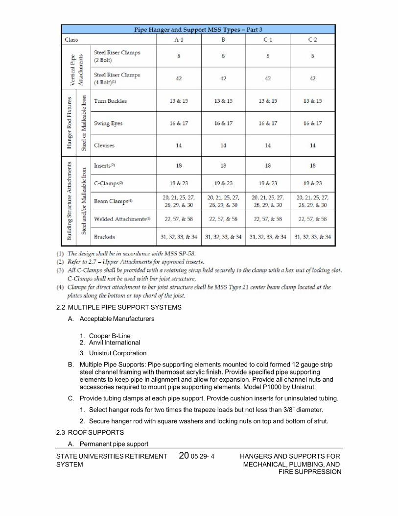
20 05 29- 4STATE UNIVERSITIES RETIREMENTSYSTEM
HANGERS AND SUPPORTS FORMECHANICAL, PLUMBING, AND
FIRE SUPPRESSION
2.2 MULTIPLE PIPE SUPPORT SYSTEMS
A. Acceptable Manufacturers
1. Cooper B‐Line 2. Anvil International
3. Unistrut Corporation
B. Multiple Pipe Supports: Pipe supporting elements mounted to cold formed 12 gauge strip steel channel framing with thermoset acrylic finish. Provide specified pipe supporting elements to keep pipe in alignment and allow for expansion. Provide all channel nuts and accessories required to mount pipe supporting elements. Model P1000 by Unistrut.
C. Provide tubing clamps at each pipe support. Provide cushion inserts for uninsulated tubing.
1. Select hanger rods for two times the trapeze loads but not less than 3/8” diameter.
2. Secure hanger rod with square washers and locking nuts on top and bottom of strut.
2.3 ROOF SUPPORTS
A. Permanent pipe support
20 05 29- 5STATE UNIVERSITIES RETIREMENTSYSTEM
HANGERS AND SUPPORTS FORMECHANICAL, PLUMBING, AND
FIRE SUPPRESSION
1. Acceptable Manufacturers:
a. Pate PRS/MPRS
2. Factory fabricated 18 gauge galvanized sheet steel support curb with fully welded corner seams, and 18 gauge galvanized steel counterflashing with galvanized steel channel track attached.
3. Vertical and horizontal adjustable roller assembly of galvanized steel channel track, galvanized steel fittings, washers and nuts and a painted cast iron roller.
4. Support shall be designed to be compatible with roofing system and roofing pitch.
5. Fixed Height Roller
a. UV resistant rubber base with fixed height electroplated cast iron MSS type 44
pipe roll. Cooper B‐Line DBR. 6. Adjustable Height Channel
a. Roof support: UV resistant rubber base with two ½” galvanized steel threaded rod
risers and one 12 gauge galvanized steel horizontal channel support. Cooper B‐Line DBE.
b. Pipe support: Electroplated cast iron MSS type 44 pipe roll
7. Fixed Height Channel
a. Roof support: UV resistant rubber base with fixed height 12 gauge galvanized steel
horizontal channel support. Cooper B‐Line DB6. b. Pipe support: Electroplated cast iron MSS type 44 pipe roll
2.4 MISCELLANEOUS MATERIALS
A. Metal Framing: Provide products complying with NEMA STD ML 1.
B. Steel Plates, Shapes and Bars: Provide products complying with ASTM A 36.
C. Cement Grout: Portland cement (ASTM C 150, Type I or Type III) and clean uniformly graded, natural sand (ASTM C 404, Size No. 2). Mix at a ratio of 1.0 part cement to 3.0 parts sand, by volume, with minimum amount of water required for placement and hydration.
PART 3 – EXECUTION
3.1 PIPE HANGERS AND SUPPORTS
A. Hanger and Support Installation
1. Thermal‐Hanger Shield Installation: Install in pipe hanger or shield for insulated piping. 2. Pipe Stand Installation:
a. Pipe Stand Types except Curb‐Mounted Type: Assemble components and mount on smooth roof surface. Do not penetrate roof membrane.
3. Install hangers and supports complete with necessary attachments, inserts, bolts, rods, nuts, washers, and other accessories.
4. Install hangers and supports to allow controlled thermal and seismic movement of piping systems, to permit freedom of movement between pipe anchors, and to facilitate action of expansion joints, expansion loops, expansion bends, and similar units.
5. Load Distribution: Install hangers and supports so that piping live and dead loads and stresses from movement will not be transmitted to connected equipment.

20 05 29- 6STATE UNIVERSITIES RETIREMENTSYSTEM
HANGERS AND SUPPORTS FORMECHANICAL, PLUMBING, AND
FIRE SUPPRESSION
6. Pipe Slopes: Install hangers and supports to provide indicated pipe slopes and to not exceed maximum pipe deflections allowed by ASME B31.9 for building services piping.
B. Hanger and Support Spacing
1. Pipe shall be adequately supported by pipe hanger and supports specified in Part 3. Hangers for insulated pipes shall be sized to accommodate insulation thickness.
2. Horizontal steel piping shall be supported in accordance with MSS SP‐69 Tables 3, 4, and 5, excerpts of which follow below:

20 05 29- 7STATE UNIVERSITIES RETIREMENTSYSTEM
HANGERS AND SUPPORTS FORMECHANICAL, PLUMBING, AND
FIRE SUPPRESSION
3.2 ROOF SUPPORTS
A. Verify that roofing system is complete and roof surfaces are smooth, flat, and ready to receive work of this section.
B. Clean surfaces of roof in areas to received supports.
C. Install in accordance with manufacturer’s instructions.
D. Pipe and Duct Supports
1. Locate bases and support framing as indicated on drawings and as specified herein. Provide complete and adequate support of all piping and ducts whether or not all required devices are shown.
2. The use of wood for supporting piping is not permitted.
3. Provide supports spaced so deflection of piping does not exceed L/240 of span.
4. Install framing at spacing indicated, but in no case at greater than 10 feet (3 m) on center.
3.3 METAL FABRICATIONS
A. Fit exposed connections together to form hairline joints. Field weld connections that cannot be shop welded because of shipping size limitations.

20 05 29- 8STATE UNIVERSITIES RETIREMENTSYSTEM
HANGERS AND SUPPORTS FORMECHANICAL, PLUMBING, AND
FIRE SUPPRESSION
B. Field Welding: Comply with AWS D1.1/D1.1M procedures for shielded, metal arc welding; appearance and quality of welds; and methods used in correcting welding work; and with the following:
1. Use materials and methods that minimize distortion and develop strength and corrosion resistance of base metals.
2. Obtain fusion without undercut or overlap.
3. Remove welding flux immediately.
4. Finish welds at exposed connections so no roughness shows after finishing and so contours of welded surfaces match adjacent contours.
3.4 ADJUSTING
A. Hanger Adjustments: Adjust hangers to distribute loads equally on attachments and to achieve indicated slope of pipe.
B. Trim excess length of continuous‐thread hanger and support rods to 1½”. C. Support Adjustment: Provide grout under supports so as to bring piping and equipment to
proper level and elevations.
3.5 PAINTING
A. Not Applicable

20 05 29- 9 STATE UNIVERSITIES RETIREMENTSYSTEM
HANGERS AND SUPPORTS FORMECHANICAL, PLUMBING, AND
FIRE SUPPRESSION

20 05 29- 10STATE UNIVERSITIES RETIREMENTSYSTEM
HANGERS AND SUPPORTS FORMECHANICAL, PLUMBING, AND
FIRE SUPPRESSION
END OF SECTION 20 05 29

20 07 00- 1STATE UNIVERSITIES RETIREMENTSYSTEM
THERMAL INSULATION FORMECHANICAL, PLUMBING, AND
FIRE SUPPRESSION
SECTION 20 07 00 - THERMAL INSULATION FOR MECHANICAL, PLUMBING, AND FIRE SUPPRESSION
PART I - GENERAL
1.1 SCOPE OF WORK
A. Thermal insulation products specifically applicable to Divisions 20 and 23, including:
1. Insulation
2. Protective coverings
3. Accessories
4. Repairs to all existing insulation cut or damaged by work performed under this Contract.
a. Products furnished but not installed under this section: None.
b. Products installed but not furnished under this section: None.
c. Services provided:
5. Design ‐None.
6. Training ‐None.
7. Obtain permits ‐None. 1.2 DEFINITIONS
A. Piping Insulation: Thermal insulation applied to prevent heat transmission to or from a piping system.
B. Ductwork Insulation: Thermal insulation applied to prevent heat transmission to or from a duct system.
C. Equipment Insulation: Thermal insulation applied to prevent heat transmission to or from a piece of equipment that is part of a plumbing, heating or cooling system.
D. Jacket: Protective covering over insulation; ‘all service jacket” or field applied to provide additional protection; of such materials as canvas, polyvinyl chloride (PVC), aluminum or stainless steel.
E. Vapor Retarder Jacket: Insulation jacket material which impedes the transmission of water vapor.
F. Insert: Spacer placed between the equipment support system and the equipment to allow for the space required for insulation.
G. Insulation Shield: Buffer material placed between the equipment support system and the insulation to prevent the insulation material from crushing.
1.3 CODES AND STANDARDS
A. American Society for Testing and Materials (ASTM)
1. ASTM A167 ‐Standard Specification for Stainless and Heat‐Resisting Chromium‐Nickel Steel Plate, Sheet, and Strip.
2. ASTM B209 ‐Standard Specification for Aluminum and Aluminum‐Alloy Sheet and Plate (ASTM B209M ‐Standard Specification for Aluminum and Aluminum‐Alloy Sheet and Plate).
20 07 00- 2STATE UNIVERSITIES RETIREMENTSYSTEM
THERMAL INSULATION FORMECHANICAL, PLUMBING, AND
FIRE SUPPRESSION
3. ASTM C177 ‐Standard Test Method for Steady‐State Heat Flux Measurements and Thermal Transmission Properties by Means of the Guarded Hot Plate Apparatus.
4. ASTM C195 ‐Standard Specification for Mineral Fiber Thermal Insulating Cement.
5. ASTM C449/C449M ‐Standard Specification for Mineral Fiber Hydraulic‐Setting Thermal Insulating and Finishing Cement.
6. ASTM C518 ‐Standard Test Method for Steady‐State Heat Flux Measurements and Thermal Transmission Properties by Means of the Heat Flow Meter Apparatus.
7. ASTM C534 ‐Standard Specification for Preformed Flexible Elastomeric Cellular Thermal Insulation in Sheet and Tubular Form.
8. ASTM C547 ‐Standard Specification for Mineral Fiber Preformed Pipe Insulation.
9. ASTM C449 ‐Mineral Fiber Hydraulic‐setting Thermal Insulating and Finishing Cement.
10. ASTM C553 ‐Mineral Fiber Blanket and Felt Insulation (Industrial Type).
11. ASTM C612 ‐Mineral Fiber Block and Board Thermal Insulation. 12. ASTM C795 ‐Standard Specification for Thermal Insulation for Use in Contact with
Austenitic Stainless Steel.
13. ASTM C921 ‐Standard Practice for Determining the Properties of Jacketing Materials for Thermal Insulation.
14. ASTM D1784 ‐Standard Specification for Rigid Poly (Vinyl Chloride) (PVC) Compounds and Chlorinated Poly (Vinyl Chloride) (CPVC) Compounds.
15. ASTM E84 ‐Standard Test Method for Surface Burning Characteristics of Building Materials.
16. ASTM E96 ‐Standard Test Methods for Water Vapor Transmission of Materials. 17.Midwest Insulation Contractors Association (MICA) ‐Commercial and Industrial Insulation Standards.
B. American Society of Heating, Refrigerating and Air‐Conditioning Engineers (ASHRAE)
1. ASHRAE Standard 90.1‐1989 Energy Efficient Design of New Buildings Except New
Low‐Rise Residential Buildings. C. National Fire Protection Association (NFPA)
1. NFPA 255 ‐Standard Method of Test of Surface Burning Characteristics of Building Materials.
2. NFPA‐90A ‐Installation of Air Conditioning and Ventilation Systems.
3. NFPA‐90B ‐Warm Air Heating and Air‐Conditioning Systems. D. National Insulation and Abatement Contractors Association (NIACA) ‐Guide to Insulation
Product Specifications.
E. North American Insulation Manufacturers Association (NAIMA) National Insulation Standards.
F. Underwriters Laboratory (UL)
1. UL 723 ‐Standard for Test for Surface Burning Characteristics of Building Materials. 1.4 QUALITY ASSURANCE
A. Manufacturer: Company specializing in manufacturing the Products specified in this section with minimum five years documented experience.

20 07 00- 3STATE UNIVERSITIES RETIREMENTSYSTEM
THERMAL INSULATION FORMECHANICAL, PLUMBING, AND
FIRE SUPPRESSION
B. Installer: Company specializing in performing the work of this section with minimum five years documented experience.
C. Products: Flame spread/smoke developed rating of 25/50 in accordance with ASTM E84 or NFPA 255 or UL 723.
D. No insulation product shall support or promote mold or fungus growth.
1.5 SUBMITTALS
A. Submit under provisions of Division 01.
B. Product Data: Provide a schedule, listing each type of insulation, thickness, density, type of protective covering, etc., and the work and service to which each type of insulation is to be applied. The schedule shall be submitted in quantities consistent with that required in th Conditions of the Contract. No insulation shall be purchased or installed until the schedule is reviewed by the Engineer.
C. Manufacturer’s Installation Instructions: Indicate specific installation instructions per the manufacturers of the various products and indicate how the system (combination of products) will be assembled. Highlight critical environmental factors such as drying time, etc., as well as any variations between the manufacturer’s installation instructions and the specified installation instructions along with a reason for the difference.
D. Manufacturer’s Certificate: Certify that products meet or exceed specified requirements.
1.6 DELIVERY, STORAGE AND HANDLING
A. Deliver products to site under provisions of Division 01.
B. Deliver products to site in containers with manufacturer’s stamp or label affixed showing fire hazard indexes of products.
C. Protect products against dirt, water, chemical and mechanical damage before, during and after installation. Do not install damaged or wet insulation; remove from project site. Damage to products prior to final acceptance of the Work shall be repaired or replaced at no additional cost to Owner.
D. Where existing insulation has been removed or disturbed, due to new connections and/or alterations, repair and replace existing insulation using materials that match existing, except where existing insulation includes asbestos material.
E. Existing insulation containing asbestos materials (or thought to contain asbestos materials) must be removed by Owner, either totally or in part, in strict accordance with OSHA Regulations utilizing OSHA approved Contractors. Repair and/or replacement of existing insulation containing asbestos shall be with new products as specified herein.
F. Maintain ambient conditions required by the manufacturer of each product.
1.7 SPARE PARTS
A. Six rolls of tape to be used for sealing penetrations in vapor retarder jackets.
1.8 WARRANTY
A. One year warranty on products and complete installation commencing at the time of Substantial Completion.
1.9 MAINTENANCE
A. Not Applicable
PART 2 – PRODUCTS
2.1 INSULATION
A. Acceptable Manufacturers
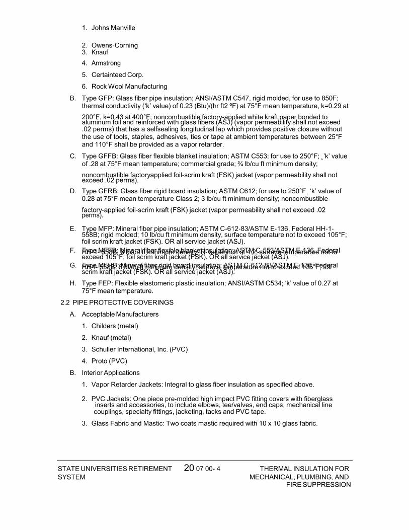
20 07 00- 4STATE UNIVERSITIES RETIREMENTSYSTEM
THERMAL INSULATION FORMECHANICAL, PLUMBING, AND
FIRE SUPPRESSION
1. Johns Manville
2. Owens‐Corning 3. Knauf
4. Armstrong
5. Certainteed Corp.
6. Rock Wool Manufacturing
B. Type GFP: Glass fiber pipe insulation; ANSI/ASTM C547, rigid molded, for use to 850F; thermal conductivity (‘k’ value) of 0.23 (Btu)/(hr ft2 ºF) at 75°F mean temperature, k=0.29 at
200°F, k=0.43 at 400°F; noncombustible factory‐applied white kraft paper bonded to aluminum foil and reinforced with glass fibers (ASJ) (vapor permeability shall not exceed .02 perms) that has a selfsealing longitudinal lap which provides positive closure without the use of tools, staples, adhesives, ties or tape at ambient temperatures between 25°F and 110°F shall be provided as a vapor retarder.
C. Type GFFB: Glass fiber flexible blanket insulation; ASTM C553; for use to 250°F; ˛’k’ value of .28 at 75°F mean temperature; commercial grade; ¾ lb/cu ft minimum density;
noncombustible factoryapplied foil‐scrim kraft (FSK) jacket (vapor permeability shall not exceed .02 perms).
D. Type GFRB: Glass fiber rigid board insulation; ASTM C612; for use to 250°Fˌ ‘k’ value of 0.28 at 75°F mean temperature Class 2; 3 lb/cu ft minimum density; noncombustible
factory‐applied foil‐scrim kraft (FSK) jacket (vapor permeability shall not exceed .02 perms).
E. Type MFP: Mineral fiber pipe insulation; ASTM C‐612‐83/ASTM E‐136, Federal HH‐1‐558B; rigid molded; 10 lb/cu ft minimum density, surface temperature not to exceed 105°F; foil scrim kraft jacket (FSK). OR all service jacket (ASJ).
F. Type MFFB: Mineral fiber flexible blanket insulation; ASTM C‐553/ASTM E‐136, Federal HH‐1‐558B; 6 lb/cu ft minimum density, R‐value/inch of 4.2, surface temperature not to exceed 105°F; foil scrim kraft jacket (FSK). OR all service jacket (ASJ).
G. Type MFRB: Mineral fiber rigid board insulation; ASTM C‐612‐83/ASTM E‐136, Federal HH‐I‐558B, 6 lb/cu ft minimum density, surface temperature not to exceed 105°F; foil scrim kraft jacket (FSK). OR all service jacket (ASJ).
H. Type FEP: Flexible elastomeric plastic insulation; ANSI/ASTM C534; ‘k’ value of 0.27 at 75°F mean temperature.
2.2 PIPE PROTECTIVE COVERINGS
A. Acceptable Manufacturers
1. Childers (metal)
2. Knauf (metal)
3. Schuller International, Inc. (PVC)
4. Proto (PVC)
B. Interior Applications
1. Vapor Retarder Jackets: Integral to glass fiber insulation as specified above.
2. PVC Jackets: One piece pre‐molded high impact PVC fitting covers with fiberglass inserts and accessories, to include elbows, tee/valves, end caps, mechanical line couplings, specialty fittings, jacketing, tacks and PVC tape.
3. Glass Fabric and Mastic: Two coats mastic required with 10 x 10 glass fabric.

20 07 00- 5STATE UNIVERSITIES RETIREMENTSYSTEM
THERMAL INSULATION FORMECHANICAL, PLUMBING, AND
FIRE SUPPRESSION
C. Exterior Applications
1. Aluminum Jackets: ASTM B209; 0.016” thick; stucco embossed
2. Stainless Steel Jackets: Type 304 stainless steel; 0.010” thick; smooth finish
3. Glass Fabric and Mastic: Two coats mastic required with 10 x 10 glass fabric.
2.3 PIPE ACCESSORIES
A. Acceptable Manufacturers
1. Foster
2. Minnesota Mining
3. Chicago Mastic
B. Insulating Cement: ANSI/ASTM C195; hydraulic setting mineral wool; compatible with the insulation and protective coverings.
C. Finishing Cement: ASTM C449; compatible with the insulation/fitting covers/jackets.
D. Adhesives and Tapes: Compatible with insulation and protective coverings.
E. Metal Jacket bands: ½” wide; 0.016” thick aluminum
PART 3 – EXECUTION
3.1 EXAMINATION
A. Install products only after piping, ductwork and equipment have been tested and approved.
B. Verify that surfaces are clean and dry with any and all foreign material removed.
C. Provide drop cloths or other means of protecting all equipment from drops, spattering, etc. which may be caused by the application of insulating products.
3.2 INSTALLATION
A. Install products in accordance with manufacturer’s and NAIMA instructions.
B. Whenever insulated pipes or ducts pass through sleeves or openings, the full specified thickness of the insulation shall pass through the sleeve or opening, except for sleeves located in fire rated partitions or floors. Space between pipe and sleeve located in fire rated partition or floor shall be sealed.
C. Contractor shall note that all adhesives shall be applied as specified, in continuous bands for complete coverage. The “spot” application of adhesives is not permitted.
D. Neatly finish insulation at supports, protrusions and interruptions.
E. Contractor shall coordinate with support and firestopping requirements as noted elsewhere in the Contract Documents.
3.3 APPLICATION (PIPING)
A. Schedule
1. INSULATION OPERATING
2. TYPE TEMP (°F)
3. Chilled Water and/or Glycol GFP
B. Insulation thickness shall be as follows:

20 07 00- 6STATE UNIVERSITIES RETIREMENTSYSTEM
THERMAL INSULATION FORMECHANICAL, PLUMBING, AND
FIRE SUPPRESSION
1. Use maximum fluid temperature for those systems where fluid temperature is above ambient temperature, minimum fluid temperature for those systems where fluid temperature is below ambient temperature.
2. EXCEPTION: Insulation thickness ɩɲɵ ɵɲɲɩ ɧɵɤɬɱɶ ɤɱɧ ɶɷɲɵɰ ɺɤɷɨɵ ɶɫɤɯɯ ɥɨ ȱ”¯
C. Indoor, Exposed Pipe
1. For pipe exposed in mechanical equipment rooms or in finished spaces, insulate pipe, fittings, joints, and valves the same as for concealed applications.
2. Locate insulation and cover seams in least visible locations on exposed piping systems.
D. Where multiple layers of pipe insulation are required, all longitudinal and circumferential joints shall be staggered.
E. Exterior Pipe
1. Insulate the same as for “Indoor, Concealed Pipe”
2. Cover pipe and fittings with aluminum jacket with seams located at 2 o’clock side of horizontal piping. Overlap jacket 90 degrees. Overlap jacket ends (do not butt together) along the length of the pipe (at least 3”) and secure jacket with aluminum bands.
F. Insulate all horizontal storm water piping as well as all vertical piping between roof drain body and the first length of vertical piping to first 90 degree elbow down. Insulate roof drain body and seal to roof slab.
G. Omit insulation on chrome‐plated exposed piping (except for physically challenged fixtures).
3.4 APPLICATION (EQUIPMENT)
A. Insulation shall be omitted at all equipment name plates and/or data plates.
B. Do not insulate factory insulated equipment.
C. Apply insulation as close as possible to equipment by grooving, scoring and beveling insulation, if necessary. Secure insulation to equipment with studs, pins, clips, adhesive, wires, or bands.
D. Fill joints, cracks, seams and depressions with bedding compound to form smooth surface. On cold equipment, use vapor retarder cement.
E. When equipment with insulation requires periodical opening for maintenance, repair, or cleaning, install insulation in such a manner that it can be easily removed and replaced without damage.

20 07 00- 7STATE UNIVERSITIES RETIREMENTSYSTEM
THERMAL INSULATION FORMECHANICAL, PLUMBING, AND
FIRE SUPPRESSION
F. Insulate cold tanks and cold heat exchangers, with 1‐1/2” thick insulation (Type FEP)

20 07 00- 8STATE UNIVERSITIES RETIREMENTSYSTEM
THERMAL INSULATION FORMECHANICAL, PLUMBING, AND
FIRE SUPPRESSION
1. Apply a coat of Foster No. 82‐31 adhesive to all surfaces to be covered and all surfaces and edges of the insulation. Press edges into place and then press or roll rest of insulation into place. Finish by sealing all joints with appropriate insulating cement.
2. After insulation has been installed, apply two coats of white vinyl lacquer finish.
3. Plate heat exchangers: only insulate fixed end plates and exterior side of splash guards. Do not insulate interior side of splash guards.
4. Insulate the following:
a. Chemical Pot Feeders
3.5 ADJUSTING
A. Not Applicable
3.6 CLEANING
A. All empty cartons, containers, etc. which have contained insulating materials shall be removed from the site and premises by the Contractor as soon as possible after their contents have been removed.
END OF SECTION 20 07 00

23 05 11- 1 STATE UNIVERSITIES RETIREMENTSYSTEM
COMMON WORK RESULTSFOR HVAC
SECTION 23 05 11 - COMMON WORK RESULTS FOR HVAC PART I - GENERAL 1.1 DESCRIPTION
A. The requirements of this Section apply to all sections of Division 23.
B. Definitions:
1. Exposed: Piping, ductwork, and equipment exposed to view in finished rooms.
2. Option or optional: Contractor's choice of an alternate material or method.
3. COR: Contracting Officer’s Representative.
1.2 RELATED WORK
A. Section 01 00 00, GENERAL REQUIREMENTS
B. Section 01 33 23, SHOP DRAWINGS, PRODUCT DATA, and SAMPLES
C. Section 07 84 00, FIRESTOPPING
D. Section 07 60 00, FLASHING AND SHEET METAL: Flashing for Wall and Roof Penetrations
E. Section 07 92 00, JOINT SEALANTS
F. Section 09 91 00, PAINTING
G. Section 23 05 41, NOISE AND VIBRATION CONTROL FOR HVAC PIPING and EQUIPMENT
H. Section 23 05 93, TESTING, ADJUSTING, and BALANCING FOR HVAC
I. Section 23 07 11, HVAC, PLUMBING, and Boiler Plant Insulation
J. Section 23 09 23, DIRECT-DIGITAL CONTROL SYSTEM FOR HVAC
K. Section 23 21 13, HYDRONIC PIPING
L. Section 23 25 00, HVAC WATER TREATMENT
M. Section 23 31 00, HVAC DUCTS and CASINGS
N. Section 23 36 00, AIR TERMINAL UNITS
O. Section 23 37 00, AIR OUTLETS and INLETS
P. Section 23 40 00, HVAC AIR CLEANING DEVICES
Q. Section 23 73 13, INDOOR CENTRAL STATION AIR HANDLING UNITS
R. Section 23 75 13, CUSTOM PACKAGED, OUTDOOR, CENTRAL-STATION AIR- HANDLING UNITS
S. Section 23 82 16, AIR COILS
T. Section 26 05 11, REQUIREMENTS FOR ELECTRICAL INSTALLATIONS
1.3 QUALITY ASSURANCE
A. Mechanical, electrical and associated systems shall be safe, reliable, efficient, durable, easily and safely operable and maintainable, easily and safely accessible, and in compliance with applicable codes as specified. The systems shall be comprised of high quality institutional class and industrial-class products of manufacturers that are

23 05 11- 2 STATE UNIVERSITIES RETIREMENTSYSTEM
COMMON WORK RESULTSFOR HVAC
experienced specialists in the required product lines. All construction firms and personnel shall be experienced and qualified specialists in industrial and institutional HVAC
B. Flow Rate Tolerance for HVAC Equipment: Section 23 05 93, TESTING, ADJUSTING, AND BALANCING FOR HVAC.
C. Equipment Vibration Tolerance:
1. Refer to Section 23 05 41, NOISE AND VIBRATION CONTROL FOR HVAC PIPING and EQUIPMENT. Equipment shall be factory-balanced to this tolerance and re- balanced on site, as necessary.
2. After HVAC air balance work is completed and permanent drive sheaves are in place, perform field mechanical balancing and adjustments required to meet the specified vibration tolerance.
D. Products Criteria:
1. Standard Products: Material and equipment shall be the standard products of a manufacturer regularly engaged in the manufacture of the products for at least 3 years (or longer as specified elsewhere). The design, model and size of each item shall have been in satisfactory and efficient operation on at least three installations for approximately three years. However, digital electronics devices, software and systems such as controls, instruments, computer work station, shall be the current generation of technology and basic design that has a proven satisfactory service record of at least three years. See other specification sections for any exceptions and/or additional requirements.
2. All items furnished shall be free from defects that would adversely affect the performance, maintainability and appearance of individual components and overall assembly.
3. Conform to codes and standards as required by the specifications. Conform to local codes, if required by local authorities such as the natural gas supplier, if the local codes are more stringent than those specified. Refer any conflicts to the COR.
4. Multiple Units: When two or more units of materials or equipment of the same type or class are required, these units shall be products of one manufacturer.
5. Assembled Units: Manufacturers of equipment assemblies, which use components made by others, assume complete responsibility for the final assembled product.
6. Nameplates: Nameplate bearing manufacturer's name or identifiable trademark shall be securely affixed in a conspicuous place on equipment, or name or trademark cast integrally with equipment, stamped or otherwise permanently marked on each item of equipment.
7. Asbestos products or equipment or materials containing asbestos shall not be used.
E. HVAC Mechanical Systems Welding: Before any welding is performed contractor shall submit a certificate certifying that welders comply with the following requirements:
1. Qualify welding processes and operators for piping according to ASME "Boiler and Pressure Vessel Code", Section IX, "Welding and Brazing Qualifications".
2. Comply with provisions of ASME B31 series "Code for Pressure Piping".
3. Certify that each welder has passed American Welding Society (AWS) qualification tests for the welding processes involved, and that certification is current.
F. Execution (Installation, Construction) Quality:
1. Apply and install all items in accordance with manufacturer's written instructions. Refer conflicts between the manufacturer's instructions and the contract drawings and specifications to the COR for resolution. Provide written hard copies or computer files of manufacturer’s installation instructions to the COR at least two weeks prior to

23 05 11- 3 STATE UNIVERSITIES RETIREMENTSYSTEM
COMMON WORK RESULTSFOR HVAC
commencing installation of any item. Installation of the item shall not be allowed to proceed until the recommendations are received. Failure to furnish these recommendations is a cause for rejection of the material.
2. Provide complete layout drawings required by Paragraph, SUBMITTALS. Do not commence construction work on any system until the layout drawings have been approved.
G. Upon request by Owner, provide lists of previous installations for selected items of equipment. Include contact persons who shall serve as references, with telephone numbers and e-mail addresses.
1.4 SUBMITTALS
A. Submit in accordance with Section 01 33 23, SHOP DRAWINGS, PRODUCT DATA AND SAMPLES, and with requirements in the individual specification sections.
B. Contractor shall make all necessary field measurements and investigations to assure that the equipment and assemblies shall meet contract requirements.
C. If equipment is submitted which differs in arrangement from that shown, provide drawings that show the rearrangement of all associated systems. Approval shall be given only if all features of the equipment and associated systems, including accessibility, are equivalent to that required by the contract.
D. Prior to submitting shop drawings for approval, contractor shall certify in writing that manufacturers of all major items of equipment have each reviewed drawings and specifications, and have jointly coordinated and properly integrated their equipment and controls to provide a complete and efficient installation.
E. Submittals and shop drawings for interdependent items, containing applicable descriptive information, shall be furnished together and complete in a group. Coordinate and properly integrate materials and equipment in each group to provide a completely compatible and efficient.
F. Samples: Samples shall not be required, except for insulation or where materials offered differ from specification requirements. Samples shall be accompanied by full description of characteristics different from specification. The Owner, at the Owner’s expense, shall perform evaluation and testing if necessary. The Contractor may submit samples of additional material at the Contractor's option; however, if additional samples of materials are submitted later, pursuant to Owner request, adjustment in contract price and time shall be made.
G. Layout Drawings:
1. Submit complete consolidated and coordinated layout drawings for all new systems, and for existing systems that are in the same areas.
2. The drawings shall include plan views, elevations and sections of all systems and shall be on a scale of not less than 1:32 (3/8-inch equal to one foot). Clearly identify and dimension the proposed locations of the principal items of equipment. The drawings shall clearly show locations and adequate clearance for all equipment, piping, valves, control panels and other items. Show the access means for all items requiring access for operations and maintenance. Provide detailed layout drawings of all piping and duct systems.
3. Do not install equipment foundations, equipment or piping until layout drawings have been approved.
4. In addition, for HVAC systems, provide details of the following:
a. Mechanical equipment rooms.
b. Interstitial space.
23 05 11- 4 STATE UNIVERSITIES RETIREMENTSYSTEM
COMMON WORK RESULTSFOR HVAC
c. Hangers, inserts, supports, and bracing.
d. Pipe sleeves.
e. Duct or equipment penetrations of floors, walls, ceilings, or roofs.
H. Manufacturer's Literature and Data: Submit under the pertinent section rather than under this section.
1. Submit belt drive with the driven equipment. Submit selection data for specific drives when requested by the COR.
2. Submit electric motor data and variable speed drive data with the driven equipment.
3. Equipment and materials identification.
4. Fire-stopping materials.
5. Hangers, inserts, supports and bracing. Provide load calculations for variable spring and constant support hangers.
6. Wall, floor, and ceiling plates.
I. HVAC Maintenance Data and Operating Instructions:
1. Maintenance and operating manuals in accordance with Section 01 00 00, GENERAL REQUIREMENTS, Article, INSTRUCTIONS, for systems and equipment.
2. Provide a listing of recommended replacement parts for keeping in stock supply, including sources of supply, for equipment. Include in the listing belts for equipment: Belt manufacturer, model number, size and style, and distinguished whether of multiple belt sets.
J. Provide copies of approved HVAC equipment submittals to the Testing, Adjusting and Balancing Subcontractor.
1.5 APPLICABLE PUBLICATIONS
A. The publications listed below form a part of this specification to the extent referenced. The publications are referenced in the text by the basic designation only.
B. Air Conditioning, Heating and Refrigeration Institute (AHRI):
430-2009................Central Station Air-Handling Units
C. American National Standard Institute (ANSI):
B31.1-2007..............Power Piping
D. Rubber Manufacturers Association (ANSI/RMA):
IP-20-2007..............Specifications for Drives Using Classical V-Belts and Sheaves IP-21-
2009..............Specifications for Drives Using Double-V (Hexagonal) Belts
IP-22-2007..............Specifications for Drives Using Narrow V-Belts and Sheaves
E. Air Movement and Control Association (AMCA):
410-96..................Recommended Safety Practices for Air Moving Devices
F. American Society of Mechanical Engineers (ASME):
Boiler and Pressure Vessel Code (BPVC):
Section I-2007..........Power Boilers
Section IX-2007.........Welding and Brazing Qualifications
Code for Pressure Piping:
B31.1-2007..............Power Piping

23 05 11- 5 STATE UNIVERSITIES RETIREMENTSYSTEM
COMMON WORK RESULTSFOR HVAC
G. American Society for Testing and Materials (ASTM):
A36/A36M-08.............Standard Specification for Carbon Structural Steel
A575-96(2007)...........Standard Specification for Steel Bars, Carbon, Merchant Quality, M- Grades
E84-10..................Standard Test Method for Surface Burning Characteristics of Building Materials
E119-09c................Standard Test Methods for Fire Tests of Building Construction and Materials
H. Manufacturers Standardization Society (MSS) of the Valve and Fittings Industry, Inc:
SP-58-2009..............Pipe Hangers and Supports-Materials, Design and Manufacture, Selection, Application, and Installation
SP 69-2003..............Pipe Hangers and Supports-Selection and Application
SP 127-2001.............Bracing for Piping Systems, Seismic – Wind – Dynamic, Design, Selection, Application
I. National Electrical Manufacturers Association (NEMA):
MG-1-2009...............Motors and Generators
J. National Fire Protection Association (NFPA):
31-06...................Standard for Installation of Oil-Burning Equipment
54-09...................National Fuel Gas Code
70-08...................National Electrical Code
85-07...................Boiler and Combustion Systems Hazards Code
90A-09..................Standard for the Installation of Air Conditioning and Ventilating Systems
101-09..................Life Safety Code
1.6 DELIVERY, STORAGE AND HANDLING
A. Protection of Equipment:
1. Equipment and material placed on the job site shall remain in the custody of the Contractor until phased acceptance, whether or not the Owner has reimbursed the Contractor for the equipment and material. The Contractor is solely responsible for the protection of such equipment and material against any damage.
2. Place damaged equipment in first class, new operating condition; or, replace same as determined and directed by the COR. Such repair or replacement shall be at no additional cost to the Owner.
3. Protect interiors of new equipment and piping systems against entry of foreign matter. Clean both inside and outside before painting or placing equipment in operation.
4. Existing equipment and piping being worked on by the Contractor shall be under the custody and responsibility of the Contractor and shall be protected as required for new work.
B. Cleanliness of Piping and Equipment Systems:
1. Exercise care in storage and handling of equipment and piping material to be incorporated in the work. Remove debris arising from cutting, threading and welding of piping.
2. Piping systems shall be flushed, blown or pigged as necessary to deliver clean systems.

23 05 11- 6 STATE UNIVERSITIES RETIREMENTSYSTEM
COMMON WORK RESULTSFOR HVAC
3. Clean interior of all tanks prior to delivery for beneficial use by the Owner.
4. Boilers shall be left clean following final internal inspection by Owner insurance representative or inspector.
5. Contractor shall be fully responsible for all costs, damage, and delay arising from failure to provide clean systems.
1.7 JOB CONDITIONS – WORK IN EXISTING BUILDING
A. Building Operation: Owner employees shall be continuously operating and managing all facilities, including temporary facilities, that serve the facility.
B. Maintenance of Service: Schedule all work to permit continuous service as required by the facility.
C. Phasing of Work: Comply with all requirements shown on drawings or specified.
D. Building Working Environment: Maintain the architectural and structural integrity of the building and the working environment at all times. Maintain the interior of building at 18 degrees C (65 degrees F) minimum. Limit the opening of doors, windows or other access openings to brief periods as necessary for rigging purposes. No storm water or ground water leakage permitted. Provide daily clean-up of construction and demolition debris on all floor surfaces and on all equipment being operated by Owner.
E. Acceptance of Work for Owner Operation: As new facilities are made available for operation and these facilities are of beneficial use to the Owner, inspections shall be made and tests shall be performed. Based on the inspections, a list of contract deficiencies shall be issued to the Contractor. After correction of deficiencies as necessary for beneficial use, the Contracting Officer shall process necessary acceptance and the equipment shall then be under the control and operation of Owner personnel.
F. Temporary Facilities: Refer to Article, TEMPORARY PIPING AND EQUIPMENT in this section.
PART 2 - PRODUCTS
2.1 FACTORY-ASSEMBLED PRODUCTS
A. Provide maximum standardization of components to reduce spare part requirements.
B. Manufacturers of equipment assemblies that include components made by others shall assume complete responsibility for final assembled unit.
1. All components of an assembled unit need not be products of same manufacturer.
2. Constituent parts that are alike shall be products of a single manufacturer.
3. Components shall be compatible with each other and with the total assembly for intended service.
4. Contractor shall guarantee performance of assemblies of components, and shall repair or replace elements of the assemblies as required to deliver specified performance of the complete assembly.
C. Components of equipment shall bear manufacturer's name and trademark, model number, serial number and performance data on a name plate securely affixed in a conspicuous place, or cast integral with, stamped or otherwise permanently marked upon the components of the equipment.
D. Major items of equipment, which serve the same function, shall be the same make and model. Exceptions shall be permitted if performance requirements cannot be met.
2.2 COMPATIBILITY OF RELATED EQUIPMENT

23 05 11- 7 STATE UNIVERSITIES RETIREMENTSYSTEM
COMMON WORK RESULTSFOR HVAC
A. Equipment and materials installed shall be compatible in all respects with other items being furnished and with existing items so that the result shall be a complete and fully operational plant that conforms to contract requirements.
2.3 BELT DRIVES
A. Type: ANSI/RMA standard V-belts with proper motor pulley and driven sheave. Belts shall be constructed of reinforced cord and rubber.
B. Dimensions, rating and selection standards: ANSI/RMA IP-20 and IP-21.
C. Minimum Horsepower Rating: Motor horsepower plus recommended ANSI/RMA service factor (not less than 20 percent) in addition to the ANSI/RMA allowances for pitch diameter, center distance, and arc of contact.
D. Maximum Speed: 25 m/s (5000 feet per minute).
E. Adjustment Provisions: For alignment and ANSI/RMA standard allowances for installation and take-up.
F. Drives may utilize a single V-Belt (any cross section) when it is the manufacturer's standard.
G. Multiple Belts: Matched to ANSI/RMA specified limits by measurement on a belt measuring fixture. Seal matched sets together to prevent mixing or partial loss of sets. Replacement, when necessary, shall be an entire set of new matched belts.
H. Sheaves and Pulleys:
1. Material: Pressed steel, or close grained cast iron.
2. Bore: Fixed or bushing type for securing to shaft with keys.
3. Balanced: Statically and dynamically.
4. Groove spacing for driving and driven pulleys shall be the same.
I. Drive Types, Based on ARI 435:
1. Provide adjustable-pitch drive as follows:
a. Fan speeds up to 1800 RPM: 7.5 kW (10 horsepower) and smaller.
b. Fan speeds over 1800 RPM: 2.2 kW (3 horsepower) and smaller.
2. Provide fixed-pitch drives for drives larger than those listed above.
3. The final fan speeds required to just meet the system CFM and pressure requirements, without throttling, shall be determined by adjustment of a temporary adjustable-pitch motor sheave or by fan law calculation if a fixed-pitch drive is used initially.
2.4 DRIVE GUARDS
A. For machinery and equipment, provide guards as shown in AMCA 410 for belts, chains, couplings, pulleys, sheaves, shafts, gears and other moving parts regardless of height above the floor to prevent damage to equipment and injury to personnel. Drive guards may be excluded where motors and drives are inside factory fabricated air handling unit casings.
B. Pump shafts and couplings shall be fully guarded by a sheet steel guard, covering coupling and shaft but not bearings. Material shall be minimum 16-gage sheet steel; ends shall be braked and drilled and attached to pump base with minimum of four 6 mm (1/4-inch) bolts. Reinforce guard as necessary to prevent side play forcing guard onto couplings.
C. V-belt and sheave assemblies shall be totally enclosed, firmly mounted, non-resonant. Guard shall be an assembly of minimum 22-gage sheet steel and expanded or perforated metal to permit observation of belts. 25 mm (one-inch) diameter hole shall be provided at each shaft centerline to permit speed measurement.

23 05 11- 8 STATE UNIVERSITIES RETIREMENTSYSTEM
COMMON WORK RESULTSFOR HVAC
D. Materials: Sheet steel, cast iron, expanded metal or wire mesh rigidly secured so as to be removable without disassembling pipe, duct, or electrical connections to equipment.
E. Access for Speed Measurement: 25 mm (One inch) diameter hole at each shaft center.
2.5 LIFTING ATTACHMENTS
A. Provide equipment with suitable lifting attachments to enable equipment to be lifted in its normal position. Lifting attachments shall withstand any handling conditions that might be encountered, without bending or distortion of shape, such as rapid lowering and braking of load.
2.6 ELECTRIC MOTORS
A. All material and equipment furnished and installation methods shall conform to the requirements of Section 23 05 12, GENERAL MOTOR REQUIREMENTS FOR HVAC AND STEAM GENERATION EQUIPMENT; and, Section 26 05 19, LOW-VOLTAGE ELECTRICAL POWER CONDUCTORS AND CABLES (600 VOLTS AND BELOW). Provide all electrical wiring, conduit, and devices necessary for the proper connection, protection and operation of the systems. Provide special energy efficient premium efficiency type motors as scheduled.
2.7 VARIABLE SPEED MOTOR CONTROLLERS
A. Refer to Section 26 05 11, REQUIREMENTS FOR ELECTRICAL INSTALLATIONS for specifications.
B. The combination of controller and motor shall be provided by the manufacturer of the driven equipment, such as pumps and fans, and shall be rated for 100 percent output performance. Multiple units of the same class of equipment, i.e. air handlers, fans, pumps, shall be product of a single manufacturer.
C. Motors shall be premium efficiency type and be approved by the motor controller manufacturer. The controller-motor combination shall be guaranteed to provide full motor nameplate horsepower in variable frequency operation. Both driving and driven motor/fan sheaves shall be fixed pitch.
D. Controller shall not add any current or voltage transients to the input AC power distribution system, DDC controls, sensitive medical equipment, or other connected electrical systems, nor shall be affected from other devices on the AC power system.
E. Controller shall be provided with the following operating features and accessories:
1. Suitable for variable torque load.
2. Provide thermal magnetic circuit breaker or fused switch with external operator and incoming line fuses. Unit shall be rated for minimum 25,000 AIC. Provide AC input line reactors (3% impedance) on incoming power line. Provide output line reactors on line between drive and motor where the distance between the breaker and motor exceeds 50 feet.
2.8 EQUIPMENT AND MATERIALS IDENTIFICATION
A. Use symbols, nomenclature and equipment numbers specified, shown on the drawings and shown in the maintenance manuals. Identification for piping is specified in Section 09 91 00, PAINTING.
B. Interior (Indoor) Equipment: Engraved nameplates, with letters not less than 48 mm (3/16- inch) high of brass with black-filled letters, or rigid black plastic with white letters specified in Section 09 91 00, PAINTING permanently fastened to the equipment. Identify unit components such as coils, filters, fans, and terminal units.
C. Exterior (Outdoor) Equipment: Brass nameplates, with engraved black filled letters, not less than 48 mm (3/16-inch) high riveted or bolted to the equipment.

23 05 11- 9 STATE UNIVERSITIES RETIREMENTSYSTEM
COMMON WORK RESULTSFOR HVAC
D. Control Items: Label all temperature and humidity sensors, controllers and control dampers. Identify and label each item as they appear on the control diagrams.
E. Valve Tags and Lists:
1. Valve tags: Engraved black filled numbers and letters not less than 13 mm (1/2-inch) high for number designation, and not less than 6.4 mm(1/4-inch) for service designation on 19 gage 38 mm (1-1/2 inches) round brass disc, attached with brass "S" hook or brass chain.
2. Valve lists: Typed or printed plastic coated card(s), sized 216 mm(8-1/2 inches) by 280 mm (11 inches) showing tag number, valve function and area of control, for each service or system. Punch sheets for a 3-ring notebook.
3. Provide detailed plan for each floor of the building indicating the location and valve number for each valve. Identify location of each valve with a color coded thumb tack in ceiling.
2.9 FIRESTOPPING
A. Section 07 84 00, FIRESTOPPING specifies an effective barrier against the spread of fire, smoke and gases where penetrations occur for piping and ductwork. Refer to Section 23 07 11, HVAC, PLUMBING, AND BOILER PLANT INSULATION, for firestop pipe and duct insulation.
2.10 GALVANIZED REPAIR COMPOUND
A. Mil. Spec. DOD-P-21035B, paint form.
2.11 HVAC PIPE AND EQUIPMENT SUPPORTS AND RESTRAINTS
A. Vibration Isolators: Refer to Section 23 05 41, NOISE AND VIBRATION CONTROL FOR HVAC PIPING AND EQUIPMENT.
B. Supports for Roof Mounted Items:
1. Equipment: Equipment rails shall be galvanized steel, minimum 1.3 mm (18 gauge), with integral baseplate, continuous welded corner seams, factory installed 50 mm by 100 mm (2 by 4) treated wood nailer, 1.3 mm (18 gauge) galvanized steel counter flashing cap with screws, built-in cant strip, (except for gypsum or tectum deck), minimum height 280 mm (11 inches). For surface insulated roof deck, provide raised cant strip to start at the upper surface of the insulation.
2. Pipe/duct pedestals: Provide a galvanized Unistrut channel welded to U-shaped mounting brackets which are secured to side of rail with galvanized lag bolts.
C. Pipe Supports: Comply with MSS SP-58. Type Numbers specified refer to this standard. For selection and application comply with MSS SP-69.D. Attachment to Concrete Building Construction:
1. Concrete insert: MSS SP-58, Type 18.
2. Self-drilling expansion shields and machine bolt expansion anchors: Permitted in concrete not less than 102 mm (four inches) thick when approved by the COR for each job condition.
3. Power-driven fasteners: Permitted in existing concrete or masonry not less than 102 mm (four inches) thick when approved by the COR for each job condition.
D. Attachment to Steel Building Construction:
1. Welded attachment: MSS SP-58, Type 22.
2. Beam clamps: MSS SP-58, Types 20, 21, 28 or 29. Type 23 C-clamp may be used for individual copper tubing up to 23mm (7/8-inch) outside diameter.
E. Attachment to existing structure: Support from existing floor/roof frame.

23 05 11- 10STATE UNIVERSITIES RETIREMENTSYSTEM
COMMON WORK RESULTSFOR HVAC
F. Attachment to Wood Construction: Wood screws or lag bolts.
G. Hanger Rods: Hot-rolled steel, ASTM A36 or A575 for allowable load listed in MSS SP-58. For piping, provide adjustment means for controlling level or slope. Types 13 or 15 turn- buckles shall provide 38 mm (1-1/2 inches) minimum of adjustment and incorporate locknuts. All-thread rods are acceptable.
H. Hangers Supporting Multiple Pipes (Trapeze Hangers): Galvanized, cold formed, lipped steel channel horizontal member, not less than 41 mm by 41 mm (1-5/8 inches by 1-5/8 inches), 2.7 mm (No. 12 gage), designed to accept special spring held, hardened steel nuts. Not permitted for steam supply and condensate piping.
1. Allowable hanger load: Manufacturers rating less 91kg (200 pounds).
2. Guide individual pipes on the horizontal member of every other trapeze hanger with 6 mm (1/4-inch) U-bolt fabricated from steel rod. Provide Type 40 insulation shield, secured by two 13mm (1/2-inch) galvanized steel bands, or preinsulated calcium silicate shield for insulated piping at each hanger.
I. Supports for Piping Systems:
1. Select hangers sized to encircle insulation on insulated piping. Refer to Section 23 07 11, HVAC, PLUMBING, AND BOILER PLANT INSULATION for insulation thickness. To protect insulation, provide Type 39 saddles for roller type supports or preinsulated calcium silicate shields. Provide Type 40 insulation shield or preinsulated calcium silicate shield at all other types of supports and hangers including those for preinsulated piping.
2. Piping Systems except High and Medium Pressure Steam (MSS SP-58):
a. Standard clevis hanger: Type 1; provide locknut.
b. Riser clamps: Type 8.
c. Wall brackets: Types 31, 32 or 33.
d. Roller supports: Type 41, 43, 44 and 46.
e. Saddle support: Type 36, 37 or 38.
f. Turnbuckle: Types 13 or 15. Preinsulate.
g. U-bolt clamp: Type 24.
h. Copper Tube:
(a) Hangers, clamps and other support material in contact with tubing shall be painted with copper colored epoxy paint, plastic coated or taped with non adhesive isolation tape to prevent electrolysis.
(b) For vertical runs use epoxy painted or plastic coated riser clamps.
(c) For supporting tube to strut: Provide epoxy painted pipe straps for copper tube or plastic inserted vibration isolation clamps.
(d) Insulated Lines: Provide pre-insulated calcium silicate shields sized for copper tube.
i. Supports for plastic or glass piping: As recommended by the pipe manufacturer with black rubber tape extending one inch beyond steel support or clamp.
3. Convertor and Expansion Tank Hangers: May be Type 1 sized for the shell diameter. Insulation where required shall cover the hangers.
J. Pre-insulated Calcium Silicate Shields:
1. Provide 360 degree water resistant high density 965 kPa (140 psi) compressive strength calcium silicate shields encased in galvanized metal.

23 05 11- 11STATE UNIVERSITIES RETIREMENTSYSTEM
COMMON WORK RESULTSFOR HVAC
2. Pre-insulated calcium silicate shields to be installed at the point of support during erection.
3. Shield thickness shall match the pipe insulation.
4. The type of shield is selected by the temperature of the pipe, the load it shall carry, and the type of support it shall be used with.
a. Shields for supporting chilled or cold water shall have insulation that extends a minimum of 1 inch past the sheet metal. Provide for an adequate vapor barrier in chilled lines.
b. The pre-insulated calcium silicate shield shall support the maximum allowable water filled span as indicated in MSS-SP 69. To support the load, the shields may have one or more of the following features: structural inserts 4138 kPa (600 psi) compressive strength, an extra bottom metal shield, or formed structural steel (ASTM A36) wear plates welded to the bottom sheet metal jacket.
5. Shields may be used on steel clevis hanger type supports, roller supports or flat surfaces.
2.12 PIPE PENETRATIONS
A. Install sleeves during construction for other than blocked out floor openings for risers in mechanical bays.
B. To prevent accidental liquid spills from passing to a lower level, provide the following:
1. For sleeves: Extend sleeve 25 mm (one inch) above finished floor and provide sealant for watertight joint.
2. For blocked out floor openings: Provide 40 mm (1-1/2 inch) angle set in silicone adhesive around opening.
3. For drilled penetrations: Provide 40 mm (1-1/2 inch) angle ring or square set in silicone adhesive around penetration.
C. Penetrations are not allowed through beams or ribs, but may be installed in concrete beam flanges. Any deviation from these requirements shall receive prior approval of COR.
D. Sheet Metal, Plastic, or Moisture-resistant Fiber Sleeves: Provide for pipe passing through floors, interior walls, and partitions, unless brass or steel pipe sleeves are specifically called for below.
E. Cast Iron or Zinc Coated Pipe Sleeves: Provide for pipe passing through exterior walls below grade. Make space between sleeve and pipe watertight with a modular or link rubber seal. Seal shall be applied at both ends of sleeve.
F. Galvanized Steel or an alternate Black Iron Pipe with asphalt coating Sleeves: Provide for pipe passing through concrete beam flanges, except where brass pipe sleeves are called for. Provide sleeve for pipe passing through floor of mechanical rooms, laundry work rooms, and animal rooms above basement. Except in mechanical rooms, connect sleeve with floor plate.
G. Brass Pipe Sleeves: Provide for pipe passing through quarry tile, terrazzo or ceramic tile floors. Connect sleeve with floor plate.
H. Sleeves are not required for wall hydrants for fire department connections or in drywall construction.
I. Sleeve Clearance: Sleeve through floors, walls, partitions, and beam flanges shall be one inch greater in diameter than external diameter of pipe. Sleeve for pipe with insulation shall be large enough to accommodate the insulation. Interior openings shall be caulked tight with fire stopping material and sealant to prevent the spread of fire, smoke, and gases.
J. Sealant and Adhesives: Shall be as specified in Section 07 92 00, JOINT SEALANTS.

23 05 11- 12STATE UNIVERSITIES RETIREMENTSYSTEM
COMMON WORK RESULTSFOR HVAC
2.13 DUCT PENETRATIONS
A. Provide curbs for roof mounted piping, ductwork and equipment. Curbs shall be 18 inches high with continuously welded seams, built-in cant strip, interior baffle with acoustic insulation, curb bottom, hinged curb adapter.
B. Provide firestopping for openings through fire and smoke barriers, maintaining minimum required rating of floor, ceiling or wall assembly. See section 07 84 00, FIRESTOPPING.
2.14 SPECIAL TOOLS AND LUBRICANTS
A. Furnish, and turn over to the COR, tools not readily available commercially, that are required for disassembly or adjustment of equipment and machinery furnished.
B. Grease Guns with Attachments for Applicable Fittings: One for each type of grease required for each motor or other equipment.
C. Refrigerant Tools: Provide system charging/Evacuation equipment, gauges, fittings, and tools required for maintenance of furnished equipment.
D. Tool Containers: Hardwood or metal, permanently identified for in tended service and mounted, or located, where directed by the COR.
E. Lubricants: A minimum of 0.95 L (one quart) of oil, and 0.45 kg (one pound) of grease, of equipment manufacturer's recommended grade and type, in unopened containers and properly identified as to use for each different application.
2.15 WALL, FLOOR AND CEILING PLATES
A. Material and Type: Chrome plated brass or chrome plated steel, one piece or split type with concealed hinge, with set screw for fastening to pipe, or sleeve. Use plates that fit tight around pipes, cover openings around pipes and cover the entire pipe sleeve projection.
B. Thickness: Not less than 2.4 mm (3/32-inch) for floor plates. For wall and ceiling plates, not less than 0.64 mm (0.025-inch) for up to 80 mm (3-inch pipe), 0.89 mm (0.035-inch) for larger pipe.
C. Locations: Use where pipe penetrates floors, walls and ceilings in exposed locations, in finished areas only. Provide a watertight joint in spaces where brass or steel pipe sleeves are specified.
2.16 ASBESTOS
A. Materials containing asbestos are not permitted.
PART 3 - EXECUTION
3.1 ARRANGEMENT AND INSTALLATION OF EQUIPMENT AND PIPING
A. Coordinate location of piping, sleeves, inserts, hangers, ductwork and equipment. Locate piping, sleeves, inserts, hangers, ductwork and equipment clear of windows, doors, openings, light outlets, and other services and utilities. Prepare equipment layout drawings to coordinate proper location and personnel access of all facilities. Submit the drawings for review as required by Part 1. Follow manufacturer's published recommendations for installation methods not otherwise specified.
B. Operating Personnel Access and Observation Provisions: Select and arrange all equipment and systems to provide clear view and easy access, without use of portable ladders, for maintenance and operation of all devices including all equipment items, valves, filters, strainers, transmitters, sensors, control devices. All gages and indicators shall be clearly visible by personnel standing on the floor or on permanent platforms. Do not reduce or change maintenance and operating space and access provisions that are shown on the drawings.
C. Equipment and Piping Support: Coordinate structural systems necessary for pipe and equipment support with pipe and equipment locations to permit proper installation.

23 05 11- 13STATE UNIVERSITIES RETIREMENTSYSTEM
COMMON WORK RESULTSFOR HVAC
D. Location of pipe sleeves, trenches and chases shall be accurately coordinated with equipment and piping locations.
E. Cutting Holes:
1. Cut holes through concrete and masonry by rotary core dril. Pneumatic hammer, impact electric, and hand or manual hammer type drill shall not be allowed, except as permitted by COR where working area space is limited.
2. Locate holes to avoid interference with structural members such as beams or grade beams. Holes shall be laid out in advance and drilling done only after approval by COR. If the Contractor considers it necessary to drill through structural members, this matter shall be referred to COR for approval.
3. Do not penetrate membrane waterproofing.
F. Interconnection of Instrumentation or Control Devices: Generally, electrical and pneumatic interconnections are not shown but shall be provided.
G. Minor Piping: Generally, small diameter pipe runs from drips and drains, water cooling, and other service are not shown but shall be provided.
H. Electrical and Pneumatic Interconnection of Controls and Instruments: This generally not shown but shall be provided. This includes interconnections of sensors, transmitters, transducers, control devices, control and instrumentation panels, instruments and computer workstations. Comply with NFPA-70.
I. Protection and Cleaning:
1. Equipment and materials shall be carefully handled, properly stored and adequately protected to prevent damage before and during installation, in accordance with the manufacturer's recommendations and as approved by the COR. Damaged or defective items in the opinion of the COR, shall be replaced.
2. Protect all finished parts of equipment, such as shafts and bearings where accessible, from rust prior to operation by means of protective grease coating and wrapping. Close pipe openings with caps or plugs during installation. Tightly cover and protect fixtures and equipment against dirt, water chemical, or mechanical injury. At completion of all work thoroughly clean fixtures, exposed materials and equipment.
J. Concrete and Grout: Use concrete and shrink compensating grout 25 MPa (3000 psi) minimum, specified in Section 03 30 00, CAST-IN-PLACE CONCRETE.
K. Install gages, thermometers, valves and other devices with due regard for ease in reading or operating and maintaining said devices. Locate and position thermometers and gages to be easily read by operator or staff standing on floor or walkway provided. Servicing shall not require dismantling adjacent equipment or pipe work.
L. Install steam piping expansion joints as per manufacturer’s recommendations.
M. Work in Existing Building:
1. Perform as specified in Article, OPERATIONS AND STORAGE AREAS, Article, ALTERATIONS, and Article, RESTORATION of the Section 01 00 00, GENERAL REQUIREMENTS for relocation of existing equipment, alterations and restoration of existing building(s).
2. As specified in Section 01 00 00, GENERAL REQUIREMENTS, Article, OPERATIONS AND STORAGE AREAS, make alterations to existing service piping at times that will least interfere with normal operation of the facility.
3. Cut required openings through existing masonry and reinforced concrete using diamond core drills. Use of pneumatic hammer type drills, impact type electric drills, and hand or manual hammer type drills, shall be permitted only with approval of the COR. Locate openings that will least effect structural slabs, columns, ribs or beams.

23 05 11- 14STATE UNIVERSITIES RETIREMENTSYSTEM
COMMON WORK RESULTSFOR HVAC
Refer to the COR for determination of proper design for openings through structural sections and opening layouts approval, prior to cutting or drilling into structure. After COR's approval, carefully cut opening through construction no larger than absolutely necessary for the required installation.
N. Switchgear/Electrical Equipment Drip Protection: Every effort shall be made to eliminate the installation of pipe above electrical and telephone switchgear. If this is not possible, encase pipe in a second pipe with a minimum of joints. Installation of piping, ductwork, leak protection apparatus or other installations foreign to the electrical installation shall be located in the space equal to the width and depth of the equipment and extending from to a height of 1.8 m (6 ft.) above the equipment of to ceiling structure, whichever is lower (NFPA 70).
O. Inaccessible Equipment:
1. Where the Owner determines that the Contractor has installed equipment not conveniently accessible for operation and maintenance, equipment shall be removed and reinstalled or remedial action performed as directed at no additional cost to the Owner.
2. The term "conveniently accessible" is defined as capable of being reached without the use of ladders, or without climbing or crawling under or over obstacles such as motors, fans, pumps, belt guards, transformers, high voltage lines, piping, and ductwork.
3.2 TEMPORARY PIPING AND EQUIPMENT
A. Continuity of operation of existing facilities shall generally require temporary installation or relocation of equipment and piping.
B. The Contractor shall provide all required facilities in accordance with the requirements of phased construction and maintenance of service. All piping and equipment shall be properly supported, sloped to drain, operate without excessive stress, and shall be insulated where injury can occur to personnel by contact with operating facilities. The requirements of Paragraph 3.1 apply.
C. Temporary facilities and piping shall be completely removed and any openings in structures sealed. Provide necessary blind flanges and caps to seal open piping remaining in service.
3.3 RIGGING
A. Design is based on application of available equipment. Openings in building structures are planned to accommodate design scheme.
B. Alternative methods of equipment delivery may be offered by Contractor and shall be considered by Owner under specified restrictions of phasing and maintenance of service as well as structural integrity of the building.
C. Close all openings in the building when not required for rigging operations to maintain proper environment in the facility for Owner operation and maintenance of service.
D. Contractor shall provide all facilities required to deliver specified equipment and place on foundations. Attachments to structures for rigging purposes and support of equipment on structures shall be Contractor's full responsibility. Upon request, the Owner shall check structure adequacy and advise Contractor of recommended restrictions.
E. Contractor shall check all clearances, weight limitations and shall offer a rigging plan designed by a Registered Professional Engineer. All modifications to structures, including reinforcement thereof, shall be at Contractor's cost, time and responsibility.
F. Rigging plan and methods shall be referred to COR for evaluation prior to actual work.
G. Restore building to original condition upon completion of rigging work.
3.4 PIPE AND EQUIPMENT SUPPORTS

23 05 11- 15STATE UNIVERSITIES RETIREMENTSYSTEM
COMMON WORK RESULTSFOR HVAC
A. Where hanger spacing does not correspond with joist or rib spacing, use structural steel channels secured directly to joist and rib structure that shall correspond to the required hanger spacing, and then suspend the equipment and piping from the channels. Drill or burn holes in structural steel only with the prior approval of the COR.
B. Use of chain, wire or strap hangers; wood for blocking, stays and bracing; or, hangers suspended from piping above shall not be permitted. Replace or thoroughly clean rusty products and paint with zinc primer.
C. Use hanger rods that are straight and vertical. Turnbuckles for vertical adjustments may be omitted where limited space prevents use. Provide a minimum of 15 mm (1/2-inch) clearance between pipe or piping covering and adjacent work.
D. HVAC Horizontal Pipe Support Spacing: Refer to MSS SP-69. Provide additional supports at valves, strainers, in-line pumps and other heavy components. Provide a support within one foot of each elbow.
E. HVAC Vertical Pipe Supports:
1. Up to 150 mm (6-inch pipe), 9 m (30 feet) long, bolt riser clamps to the pipe below couplings, or welded to the pipe and rests supports securely on the building structure.
2. Vertical pipe larger than the foregoing, support on base elbows or tees, or substantial pipe legs extending to the building structure.
F. Overhead Supports:
1. The basic structural system of the building is designed to sustain the loads imposed by equipment and piping to be supported overhead.
2. Provide steel structural members, in addition to those shown, of adequate capability to support the imposed loads, located in accordance with the final approved layout of equipment and piping.
3. Tubing and capillary systems shall be supported in channel troughs.
G. Floor Supports:
1. Provide concrete bases, concrete anchor blocks and pedestals, and structural steel systems for support of equipment and piping. Anchor and dowel concrete bases and structural systems to resist forces under operating and seismic conditions (if applicable) without excessive displacement or structural failure.
2. Do not locate or install bases and supports until equipment mounted thereon has been approved. Size bases to match equipment mounted thereon plus 50 mm (2 inch) excess on all edges. Boiler foundations shall have horizontal dimensions that exceed boiler base frame dimensions by at least 150 mm (6 inches) on all sides. Refer to structural drawings. Bases shall be neatly finished and smoothed, shall have chamfered edges at the top, and shall be suitable for painting.
3. All equipment shall be shimmed, leveled, firmly anchored, and grouted with epoxy grout. Anchor bolts shall be placed in sleeves, anchored to the bases. Fill the annular space between sleeves and bolts with a granular material to permit alignment and realignment.
3.5 MECHANICAL DEMOLITION
A. Rigging access, other than indicated on the drawings, shall be provided by the Contractor after approval for structural integrity by the COR. Such access shall be provided without additional cost or time to the Owner. Where work is in an operating plant, provide approved protection from dust and debris at all times for the safety of plant personnel and maintenance of plant operation and environment of the plant.
B. In an operating facility, maintain the operation, cleanliness and safety. Owner personnel shall be carrying on their normal duties of operating, cleaning and maintaining equipment

23 05 11- 16STATE UNIVERSITIES RETIREMENTSYSTEM
COMMON WORK RESULTSFOR HVAC
and plant operation. Confine the work to the immediate area concerned; maintain cleanliness and wet down demolished materials to eliminate dust. Do not permit debris to accumulate in the area to the detriment of plant operation. Perform all flame cutting to maintain the fire safety integrity of this plant. Adequate fire extinguishing facilities shall be available at all times. Perform all work in accordance with recognized fire protection standards. Inspection shall be made by personnel of the Owner, and Contractor shall follow all directives of the RE or COR with regard to rigging, safety, fire safety, and maintenance of operations.
C. Completely remove all piping, wiring, conduit, and other devices associated with the equipment not to be re-used in the new work. This includes all pipe, valves, fittings, insulation, and all hangers including the top connection and any fastenings to building structural systems. Seal all openings, after removal of equipment, pipes, ducts, and other penetrations in roof, walls, floors, in an approved manner and in accordance with plans and specifications where specifically covered. Structural integrity of the building system shall be maintained. Reference shall also be made to the drawings and specifications of the other disciplines in the project for additional facilities to be demolished or handled.
D. All valves including gate, globe, ball, butterfly and check, all pressure gages and thermometers with wells shall remain Owner property and shall be removed and delivered to COR and stored as directed. The Contractor shall remove all other material and equipment, devices and demolition debris under these plans and specifications. Such material shall be removed from Owner property expeditiously and shall not be allowed to accumulate.
3.6 CLEANING AND PAINTING
A. Prior to final inspection and acceptance of the plant and facilities for beneficial use by the Owner, the plant facilities, equipment and systems shall be thoroughly cleaned and painted. Refer to Section 09 9100, PAINTING.
B. In addition, the following special conditions apply:
1. Cleaning shall be thorough. Use solvents, cleaning materials and methods recommended by the manufacturers for the specific tasks. Remove all rust prior to painting and from surfaces to remain unpainted. Repair scratches, scuffs, and abrasions prior to applying prime and finish coats.
2. Material And Equipment Not To Be Painted Includes:
a. Motors, controllers, control switches, and safety switches.
b. Control and interlock devices.
c. Regulators.
d. Pressure reducing valves.
e. Control valves and thermostatic elements.
f. Lubrication devices and grease fittings.
g. Copper, brass, aluminum, stainless steel and bronze surfaces.
h. Valve stems and rotating shafts.
i. Pressure gauges and thermometers.
j. Glass.
k. Name plates.
3. Control and instrument panels shall be cleaned, damaged surfaces repaired, and shall be touched-up with matching paint obtained from panel manufacturer.
4. Pumps, motors, steel and cast iron bases, and coupling guards shall be cleaned, and shall be touched-up with the same color as utilized by the pump manufacturer

23 05 11- 17STATE UNIVERSITIES RETIREMENTSYSTEM
COMMON WORK RESULTSFOR HVAC
5. Temporary Facilities: Apply paint to surfaces that do not have existing finish coats.
6. Paint shall withstand the following temperatures without peeling or discoloration:
a. Condensate and feedwater -- 38 degrees C (100 degrees F) on insulation jacket surface and 120 degrees C (250 degrees F) on metal pipe surface.
b. Steam -- 52 degrees C (125 degrees F) on insulation jacket surface and 190 degrees C (375 degrees F) on metal pipe surface.
7. Final result shall be smooth, even-colored, even-textured factory finish on all items. Completely repaint the entire piece of equipment if necessary to achieve this.
3.7 IDENTIFICATION SIGNS
A. Provide laminated plastic signs, with engraved lettering not less than 5 mm (3/16-inch) high, designating functions, for all equipment, switches, motor controllers, relays, meters, control devices, including automatic control valves. Nomenclature and identification symbols shall correspond to that used in maintenance manual, and in diagrams specified elsewhere. Attach by chain, adhesive, or screws.
B. Factory Built Equipment: Metal plate, securely attached, with name and address of manufacturer, serial number, model number, size, performance.
C. Pipe Identification: Refer to Section 09 91 00, PAINTING.
3.8 MOTOR AND DRIVE ALIGNMENT
A. Belt Drive: Set driving and driven shafts parallel and align so that the corresponding grooves are in the same plane.
B. Direct-connect Drive: Securely mount motor in accurate alignment so that shafts are free from both angular and parallel misalignment when both motor and driven machine are operating at normal temperatures.
3.9 LUBRICATION
A. Lubricate all devices requiring lubrication prior to initial operation. Field-check all devices for proper lubrication.
B. Equip all devices with required lubrication fittings or devices. Provide a minimum of one liter (one quart) of oil and 0.5 kg (one pound) of grease of manufacturer's recommended grade and type for each different application; also provide 12 grease sticks for lubricated plug valves. Deliver all materials to COR in unopened containers that are properly identified as to application.
C. Provide a separate grease gun with attachments for applicable fittings for each type of grease applied.
D. All lubrication points shall be accessible without disassembling equipment, except to remove access plates.
3.10 STARTUP AND TEMPORARY OPERATION
A. Start up equipment as described in equipment specifications. Verify that vibration is within specified tolerance prior to extended operation. Temporary use of equipment is specified in Section 01 00 00, GENERAL REQUIREMENTS, Article, TEMPORARY USE OF MECHANICAL AND ELECTRICAL EQUIPMENT.
3.11 OPERATING AND PERFORMANCE TESTS
A. Prior to the final inspection, perform required tests as specified in Section 01 00 00, GENERAL REQUIREMENTS and submit the test reports and records to the COR.
B. Should evidence of malfunction in any tested system, or piece of equipment or component part thereof, occur during or as a result of tests, make proper corrections, repairs or replacements, and repeat tests at no additional cost to the Owner.

23 05 11- 18STATE UNIVERSITIES RETIREMENTSYSTEM
COMMON WORK RESULTSFOR HVAC
C. When completion of certain work or system occurs at a time when final control settings and adjustments cannot be properly made to make performance tests, then make performance tests for heating systems and for cooling systems respectively during first actual seasonal use of respective systems following completion of work.
END OF SECTION 23 05 11

23 05 12- 1STATE UNIVERSITIES RETIREMENTSYSTEM
GENERAL MOTOR REQUIREMENTSFOR HVAC AND STEAM
GENERATION EQUIPMENT
SECTION 23 05 12 - GENERAL MOTOR REQUIREMENTS FOR HVAC AND STEAM GENERATION EQUIPMENT
PART I - GENERAL
1.1 DESCRIPTION
A. This section specifies the furnishing, installation and connection of
B. motors for HVAC and steam generation equipment.
1.2 RELATED WORK:
A. Section 26 05 11, REQUIREMENTS FOR ELECTRICAL INSTALLATIONS: General electrical requirements common to more than one Section of Division 26. assemblies, which include motor starters.
B. Section 23 05 11, COMMON WORK RESULTS FOR HVAC.
C. Section 23 36 00, AIR TERMINAL UNITS.
D. Section 23 74 13, PACKAGED, OUTDOOR, CENTRAL-STATION AIR-HANDLING UNITS.
1.3 SUBMITTALS:
A. In accordance with Section 26 05 11, REQUIREMENTS FOR ELECTRICAL INSTALLATIONS, submit the following:
B. Shop Drawings:
1. Provide documentation to demonstrate compliance with drawings and specifications.
2. Include electrical ratings, efficiency, bearing data, power factor, frame size, dimensions, mounting details, materials, horsepower, voltage, phase, speed (RPM), enclosure, starting characteristics, torque characteristics, code letter, full load and locked rotor current, service factor, and lubrication method.
C. Manuals:
1. Submit simultaneously with the shop drawings, companion copies of complete installation, maintenance and operating manuals, including technical data sheets and application data.
D. Certification: Two weeks prior to final inspection, unless otherwise noted, submit four copies of the following certification to the COR:
1. Certification that the motors have been applied, installed, adjusted, lubricated, and tested according to manufacturer published recommendations.
E. Completed System Readiness Checklists provided by the Commissioning Agent and completed by the contractor, signed by a qualified technician and dated on the date of completion, in accordance with the requirements of Section 23 08 00 COMMISSIONING OF HVAC SYSTEMS.
1.4 APPLICABLE PUBLICATIONS:
A. The publications listed below form a part of this specification to the extent referenced. The publications are referenced in the text by the basic designation only.
B. National Electrical Manufacturers Association (NEMA):
MG 1-2006 Rev. 1 2009 ..Motors and Generators

23 05 12- 2STATE UNIVERSITIES RETIREMENTSYSTEM
GENERAL MOTOR REQUIREMENTSFOR HVAC AND STEAM
GENERATION EQUIPMENT
MG 2–2001 Rev. 1 2007...Safety Standard for Construction and Guide for Selection, Installation and Use of Electric Motors and Generators
C. National Fire Protection Association (NFPA):
70-2008.................National Electrical Code (NEC)
D. Institute of Electrical and Electronics Engineers (IEEE):
112-04..................Standard Test Procedure for Polyphase Induction Motors and Generators
E. American Society of Heating, Refrigerating and Air-Conditioning Engineers (ASHRAE):
90.1-2007...............Energy Standard for Buildings Except Low-Rise Residential Buildings
PART 2 – PRODUCTS
2.1 MOTORS:
A. For alternating current, fractional and integral horsepower motors, NEMA Publications MG 1 and MG 2 shall apply.
B. All material and equipment furnished and installation methods shall conform to the requirements of Section 26 05 19, LOW-VOLTAGE ELECTRICAL POWER CONDUCTORS AND CABLES (600 VOLTS AND BELOW). Provide all electrical wiring, conduit, and devices necessary for the proper connection, protection and operation of the systems. Provide premium efficiency type motors as scheduled. Unless otherwise specified for a particular application, use electric motors with the following requirements.
C. Single-phase Motors: Motors for centrifugal fans and pumps shall be split phase or permanent split capacitor (PSC) type. Provide capacitor start type for hard starting applications.
D. Voltage ratings shall be as follows:
1. Single phase:
a. Motors connected to 120-volt systems: 115 volts.
b. Motors connected to 208-volt systems: 200 volts.
c. Motors connected to 240 volt or 480 volt systems: 230/460 volts, dual connection.
2. Three phase:
a. Motors connected to 208-volt systems: 200 volts.
b. Motors, less than 74.6 kW (100 HP), connected to 240 volt or 480 volt systems: 208-230/460 volts, dual connection.
E. Number of phases shall be as follows:
1. Motors, less than 373 W (1/2 HP): Single phase.
2. Motors, 373 W (1/2 HP) and larger: 3 phase.
3. Exceptions:
a. Hermetically sealed motors.
b. Motors for equipment assemblies, less than 746 W (one HP), shall be single phase provided the manufacturer of the proposed assemblies cannot supply the assemblies with three phase motors.
F. Motors shall be designed for operating the connected loads continuously in a 40°C (104°F) environment, where the motors are installed, without exceeding the NEMA standard temperature rises for the motor insulation. If the motors exceed 40°C (104°F), the motors shall be rated for the actual ambient temperatures.

23 05 12- 3STATE UNIVERSITIES RETIREMENTSYSTEM
GENERAL MOTOR REQUIREMENTSFOR HVAC AND STEAM
GENERATION EQUIPMENT
G. Motor designs, as indicated by the NEMA code letters, shall be coordinated with the connected loads to assure adequate starting and running torque.
H. Motor Enclosures:
1. Shall be the NEMA types as specified and/or shown on the drawings.
2. Where the types of motor enclosures are not shown on the drawings, they shall be the NEMA types, which are most suitable for the environmental conditions where the motors are being installed. Enclosure requirements for certain conditions are as follows:
a. Motors located outdoors, indoors in wet or high humidity locations, or in unfiltered airstreams shall be totally enclosed type.
b. Where motors are located in an NEC 511 classified area, provide TEFC explosion proof motor enclosures.
c. Where motors are located in a corrosive environment, provide TEFC enclosures with corrosion resistant finish.
3. Enclosures shall be primed and finish coated at the factory with manufacturer's prime coat and standard finish.
I. Special Requirements:
1. Where motor power requirements of equipment furnished deviate from power shown on plans, provide electrical service designed under the requirements of NFPA 70 without additional time or cost to the Owner.
2. Assemblies of motors, starters, controls and interlocks on factory assembled and wired devices shall be in accordance with the requirements of this specification.
3. Wire and cable materials specified in the electrical division of the specifications shall be modified as follows:
a. Wiring material located where temperatures can exceed 71 degrees C (160 degrees F) shall be stranded copper with Teflon FEP insulation with jacket. This includes wiring on the boilers.
b. Other wiring at boilers and to control panels shall be NFPA 70 designation THWN.
c. Provide shielded conductors or wiring in separate conduits for all instrumentation and control systems where recommended by manufacturer of equipment.
4. Select motor sizes so that the motors do not operate into the service factor at maximum required loads on the driven equipment. Motors on pumps shall be sized for non-overloading at all points on the pump performance curves.
5. Motors utilized with variable frequency drives shall be rated “inverter-duty” per NEMA Standard, MG1, Part 31.4.4.2. Provide motor shaft grounding apparatus that shall protect bearings from damage from stray currents.
J. Additional requirements for specific motors, as indicated in the other sections listed in Article 1.2, shall also apply.
K. Energy-Efficient Motors (Motor Efficiencies): All permanently wired polyphase motors of 746 Watts (1 HP) or more shall meet the minimum full-load efficiencies as indicated in the following table. Motors of 746 Watts or more with open, drip-proof or totally enclosed fan- cooled enclosures shall be NEMA premium efficiency type, unless otherwise indicated. Motors provided as an integral part of motor driven equipment are excluded from this requirement if a minimum seasonal or overall efficiency requirement is indicated for that equipment by the provisions of another section. Motors not specified as “premium efficiency” shall comply with the Energy Policy Act of 2005 (EPACT).

23 05 12- 4STATE UNIVERSITIES RETIREMENTSYSTEM
GENERAL MOTOR REQUIREMENTSFOR HVAC AND STEAM
GENERATION EQUIPMENT
L. Minimum Power Factor at Full Load and Rated Voltage: 90 percent at 1200 RPM, 1800 RPM and 3600 RPM.
PART 3 - EXECUTION
3.1 INSTALLATION:
A. Install motors in accordance with manufacturer’s recommendations, the NEC, NEMA, as shown on the drawings and/or as required by other sections of these specifications.
3.2 FIELD TESTS
A. Perform an electric insulation resistance Test using a megohmmeter on all motors after installation, before start-up. All shall test free from grounds.
B. Perform Load test in accordance with ANSI/IEEE 112, Test Method B, to determine freedom from electrical or mechanical defects and compliance with performance data.
C. Insulation Resistance: Not less than one-half meg-ohm between stator conductors and frame, to be determined at the time of final inspection.
3.3 STARTUP AND TESTING
A. The Commissioning Agent shall observe startup and contractor testing of selected equipment. Coordinate the startup and contractor testing schedules with COR and Commissioning Agent. Provide a minimum of 7 days prior notice.
3.4 DEMONSTRATION AND TRAINING
A. Provide services of manufacturer’s technical representative for four hours to instruct Owner personnel in operation and maintenance of units.

23 05 12- 5STATE UNIVERSITIES RETIREMENTSYSTEM
GENERAL MOTOR REQUIREMENTSFOR HVAC AND STEAM
GENERATION EQUIPMENT
B. Submit training plans and instructor qualifications in accordance with the requirements of Section 23 08 00 – COMMISSIONING OF HVAC SYSTEMS.
END OF SECTION 23 05 12

23 05 41- 1STATE UNIVERSITIES RETIREMENTSYSTEM
NOISE AND VIBRATIONCONTROL FOR HVAC
PIPING AND EQUIPMENT
SECTION 23 05 41 - NOISE AND VIBRATION CONTROL FOR HVAC PIPING AND EQUIPMENT
PART I - GENERAL 1.1 DESCRIPTION
A. Noise criteria, vibration tolerance and vibration isolation for HVAC and plumbing work.
1.2 RELATED WORK
A. Section 23 05 11, COMMON WORK RESULTS FOR HVAC: General mechanical requirements and items, which are common to more than one section of Division 23.
B. Section 23 22 13, STEAM and CONDENSATE HEATING PIPING: Requirements for flexible pipe connectors to reciprocating and rotating mechanical equipment.
C. Section 23 31 00, HVAC DUCTS and CASINGS: requirements for flexible duct connectors, sound attenuators and sound absorbing duct lining.
D. SECTION 23 05 93, TESTING, ADJUSTING, and BALANCING FOR HVAC: requirements for sound and vibration tests.
E. SECTION 23 37 00, AIR OUTLETS and INLETS: noise requirements for Ggrilles.
1.3 QUALITY ASSURANCE
A. Refer to article, QUALITY ASSURANCE in specification Section 23 05 11, COMMON WORK RESULTS FOR HVAC.
B. Noise Criteria:
1. Noise levels in all 8 octave bands due to equipment and duct systems shall not exceed following NC levels:
2. For equipment which has no sound power ratings scheduled on the plans, the contractor shall select equipment such that the foregoing noise criteria, local ordinance noise levels, and OSHA requirements are not exceeded. Selection procedure shall be in accordance with ASHRAE Fundamentals Handbook, Chapter 7, Sound and Vibration.
3. An allowance, not to exceed 5db, shall be added to the measured value to compensate for the variation of the room attenuating effect between room test

23 05 41- 2STATE UNIVERSITIES RETIREMENTSYSTEM
NOISE AND VIBRATIONCONTROL FOR HVAC
PIPING AND EQUIPMENT
condition prior to occupancy and design condition after occupancy which shall include the addition of sound absorbing material, such as, furniture. This allowance may not be taken after occupancy. The room attenuating effect is defined as the difference between sound power level emitted to room and sound pressure levelin room.
4. In absence of specified measurement requirements, measure equipment noise levels three feet from equipment and at an elevation of maximum noise generation.
C. Allowable Vibration Tolerances for Rotating, Non-reciprocating Equipment: Not to exceed a self-excited vibration maximum velocity of 5 mm per second (0.20 inch per second) RMS, filter in, when measured with a vibration meter on bearing caps of machine in vertical, horizontal and axial directions or measured at equipment mounting feet if bearings are concealed. Measurements for internally isolated fans and motors shall be made at the mounting feet.
1.4 SUBMITTALS
A. Submit in accordance with specification Section 01 33 23, SHOP DRAWINGS, PRODUCT DATA, and SAMPLES.
B. Manufacturer's Literature and Data:
1. Vibration isolators:
a. Floor mountings
b. Hangers
2. Bases.
C. Isolator manufacturer shall furnish with submittal load calculations for selection of isolators, including supplemental bases, based on lowest operating speed of equipment supported.
1.5 APPLICABLE PUBLICATIONS
A. The publications listed below form a part of this specification to the extent referenced. The publications are referenced in the text by the basic designation only.
B. American Society of Heating, Refrigerating and Air-Conditioning Engineers, Inc. (ASHRAE): 2009 ...................Fundamentals Handbook, Chapter 7, Sound and Vibration
C. American Society for Testing and Materials (ASTM):
A123/A123M-09...........Standard Specification for Zinc (Hot-Dip Galvanized) Coatings on Iron and Steel Products
A307-07b................Standard Specification for Carbon Steel Bolts and Studs, 60,000 PSI Tensile Strength
D2240-05(2010)..........Standard Test Method for Rubber Property - Durometer Hardness
D. Manufacturers Standardization (MSS):
SP-58-2009..............Pipe Hangers and Supports-Materials, Design and Manufacture
E. Occupational Safety and Health Administration (OSHA):
29 CFR 1910.95..........Occupational Noise Exposure
F. American Society of Civil Engineers (ASCE):
ASCE 7-10 ..............Minimum Design Loads for Buildings and Other Structures.
G. American National Standards Institute / Sheet Metal and Air Conditioning Contractor’s National Association (ANSI/SMACNA):
001-2008................Seismic Restraint Manual: Guidelines for Mechanical Systems, 3rd Edition.
H. International Code Council (ICC):

23 05 41- 3STATE UNIVERSITIES RETIREMENTSYSTEM
NOISE AND VIBRATIONCONTROL FOR HVAC
PIPING AND EQUIPMENT
2009 IBC................International Building Code.
PART 2 – PRODUCTS
2.1 GENERAL REQUIREMENTS
A. Type of isolator, base, and minimum static deflection shall be as required for each specific equipment application as recommended by isolator or equipment manufacturer but subject to minimum requirements indicated herein and in the schedule on the drawings.
B. Elastometric Isolators shall comply with ASTM D2240 and be oil resistant neoprene with a maximum stiffness of 60 durometer and have a straight-line deflection curve.
C. Exposure to weather: Isolator housings to be either hot dipped galvanized or powder coated to ASTM B117 salt spray testing standards. Springs to be powder coated or electro galvanized. All hardware to be electro galvanized. In addition provide limit stops to resist wind velocity. Velocity pressure established by wind shall be calculated in accordance with section 1609 of the International Building Code. A minimum wind velocity of 75 mph shall be employed.
D. Uniform Loading: Select and locate isolators to produce uniform loading and deflection even when equipment weight is not evenly distributed.
E. Color code isolators by type and size for easy identification of capacity.
2.2 BASES
A. Curb Mounted Isolation Base (Type CB): Fabricate from aluminum to fit on top of standard curb with overlap to allow water run-off and have wind and water seals which shall not interfere with spring action. Provide resilient snubbers with 6 mm (1/4 inch) clearance for wind resistance. Top and bottom bearing surfaces shall have sponge type weather seals. Integral spring isolators shall comply with Spring Isolator (Type S) requirements.
PART 3 – EXECUTION
3.1 INSTALLATION
A. Vibration Isolation:
1. No metal-to-metal contact shall be permitted between fixed and floating parts.
2. Connections to Equipment: Allow for deflections equal to or greater than equipment deflections. Electrical, drain, piping connections, and other items made to rotating or reciprocating equipment (pumps, compressors, fans) which rests on vibration isolators, shall be isolated from building structure for first three hangers or supports with a deflection equal to that used on the corresponding equipment.
3. Common Foundation: Mount each electric motor on same foundation as driven machine. Hold driving motor and driven machine in positive rigid alignment with provision for adjusting motor alignment and belt tension. Bases shall be level throughout length and width. Provide shims to facilitate pipe connections, leveling, and bolting.
4. Provide heat shields where elastomers are subject to temperatures over 38 degrees C (l00 degrees F).
5. Extend bases for pipe elbow supports at discharge and suction connections at pumps. Pipe elbow supports shall not short circuit pump vibration to structure.
6. Non-rotating equipment such as heat exchangers and convertors shall be mounted on isolation units having the same static deflection as the isolation hangers or support of the pipe connected to the equipment.
B. Inspection and Adjustments: Check for vibration and noise transmission through connections, piping, ductwork, foundations, and walls. Adjust, repair, or replace isolators as required to reduce vibration and noise transmissions to specified levels.

23 05 41- 4STATE UNIVERSITIES RETIREMENTSYSTEM
NOISE AND VIBRATIONCONTROL FOR HVAC
PIPING AND EQUIPMENT
3.2 ADJUSTING
A. Adjust vibration isolators after piping systems are filled and equipment is at operating weight.
B. Adjust limit stops on restrained spring isolators to mount equipment at normal operating height. After equipment installation is complete, adjust limit stops so they are out of contact during normal operation.
C. Attach thrust limits at centerline of thrust and adjust to a maximum of 1/4inch (6-mm) movement during start and stop.
D. Adjust active height of spring isolators.
E. Adjust snubbers according to manufacturer's recommendations.
F. Adjust seismic restraints to permit free movement of equipment within normal mode of operation.
G. Torque anchor bolts according to equipment manufacturer's recommendations to resist seismic forces.
END OF SECTION 23 05 41

23 05 93- 1STATE UNIVERSITIES RETIREMENTSYSTEM
TESTING, ADJUSTINGAND BALANCING FOR HVAC
SECTION 23 05 93 - TESTING, ADJUSTING, AND BALANCING FOR HVAC
PART I - GENERAL
1.1 DESCRIPTION
A. Testing, adjusting, and balancing (TAB) of heating, ventilating and air conditioning (HVAC) systems. TAB includes the following:
1. Planning systematic TAB procedures.
2. Design Review Report.
3. Systems Inspection report.
4. Duct Air Leakage test report.
5. Systems Readiness Report.
6. Balancing air and water distribution systems; adjustment of total system to provide design performance; and testing performance of equipment and automatic controls.
7. Vibration and sound measurements.
8. Recording and reporting results.
B. Definitions:
1. Basic TAB used in this Section: Chapter 37, "Testing, Adjusting and Balancing" of 2007 ASHRAE Handbook, "HVAC Applications".
2. TAB: Testing, Adjusting and Balancing; the process of checking and adjusting HVAC systems to meet design objectives.
3. AABC: Associated Air Balance Council.
4. NEBB: National Environmental Balancing Bureau.
5. Hydronic Systems: Includes chilled water, heating hot water.
6. Air Systems: Includes all outside air, supply air, return air, exhaust air and relief air systems.
7. Flow rate tolerance: The allowable percentage variation, minus to plus, of actual flow rate from values (design) in the contract documents.
1.2 RELATED WORK
A. Section 23 05 11, COMMON WORK RESULTS FOR HVAC: General Mechanical Requirements.
B. Section 23 05 41, NOISE AND VIBRATION CONTROL FOR HVAC PIPING AND EQUIPMENT: Noise and Vibration Requirements.
C. Section 23 07 11, HVAC AND BOILER PLANT INSULATION: Piping and Equipment Insulation.
D. Section 23 36 00, AIR TERMINAL UNITS: Terminal Units Performance.
E. Section 23 31 00, HVAC DUCTS AND CASINGS: Duct Leakage.
F. Section 23 09 23, DIRECT-DIGITAL CONTROL SYSTEM FOR HVAC: Controls and Instrumentation Settings.

23 05 93- 2STATE UNIVERSITIES RETIREMENTSYSTEM
TESTING, ADJUSTINGAND BALANCING FOR HVAC
G. Section 23 82 16, AIR COILS
H. Section 23 74 13, PACKAGED, OUTDOOR, CENTRAL-STATION AIR-HANDLING UNITS
I. Section 23 37 00, AIR OUTLETS AND INLETS
J. Section 23 21 13, HYDRONIC PIPING
K. Section 23 05 12 GENERAL MOTOR REQUIREMENTS FOR HVAC AND STEAM GENERATION EQUIPMENT
1.3 QUALITY ASSURANCE
A. Refer to Articles, Quality Assurance and Submittals, in Section 23 05 11, COMMON WORK RESULTS FOR HVAC, and Section 23 08 00, COMMISSIONING OF HVAC SYSTEMS.
B. Qualifications:
1. TAB Agency: The TAB agency shall be a subcontractor of the General Contractor and shall be assigned to and be paid by the Prime Contractor.
2. The TAB agency shall be either a certified member of AABC or certified by the NEBB to perform TAB service for HVAC, water balancing and vibrations and sound testing of equipment. The certification shall be maintained for the entire duration of duties specified herein. If, for any reason, the agency loses subject certification during this period, the General Contractor shall immediately notify the COR and submit another TAB firm for approval. Any agency that has been the subject of disciplinary action by either the AABC or the NEBB within the three years preceding Contract Award shall not be eligible to perform any work related to the TAB. All work performed in this Section and in other related Sections by the TAB agency shall be considered invalid if the TAB agency loses its certification prior to Contract completion, and the successor agency’s review shows unsatisfactory work performed by the predecessor agency.
3. TAB Specialist: The TAB specialist shall be either a member of AABC or an experienced technician of the Agency certified by NEBB. The certification shall be maintained for the entire duration of duties specified herein. If, for any reason, the Specialist loses subject certification during this period, the General Contractor shall immediately notify the COR and submit another TAB Specialist for approval. Any individual that has been the subject of disciplinary action by either the AABC or the NEBB within the three years preceding Contract Award shall not be eligible to perform any duties related to the HVAC systems, including TAB. All work specified in this Section and in other related Sections performed by the TAB specialist shall be considered invalid if the TAB Specialist loses its certification prior to Contract completion and must be performed by an approved successor.
4. TAB Specialist shall be identified by the General Contractor within 60 calendar days after the notice to proceed. The TAB specialist shall be coordinating, scheduling and reporting all TAB work and related activities and shall provide necessary information as required by the COR. The responsibilities would specifically include:
a. Shall directly supervise all TAB work.
b. Shall sign the TAB reports that bear the seal of the TAB standard. The reports shall be accompanied by report forms and schematic drawings required by the TAB standard, AABC or NEBB.
c. Would follow all TAB work through its satisfactory completion.
d. Shall provide final markings of settings of all HVAC adjustment devices.
e. Permanently mark location of duct test ports.

23 05 93- 3STATE UNIVERSITIES RETIREMENTSYSTEM
TESTING, ADJUSTINGAND BALANCING FOR HVAC
5. All TAB technicians performing actual TAB work shall be experienced and shall have completed satisfactory work on a minimum of 3 projects comparable in size and complexity to this project. Qualifications shall be certified by the TAB agency in writing. The lead technician shall be certified by AABC or NEBB
C. Test Equipment Criteria: The instrumentation shall meet the accuracy/calibration requirements established by AABC National Standards or by NEBB Procedural Standards for Testing, Adjusting and Balancing of Environmental Systems and instrument manufacturer. Provide calibration history of the instruments to be used for test and balance purpose.
D. Tab Criteria:
1. One or more of the applicable AABC, NEBB or SMACNA publications, supplemented by ASHRAE Handbook "HVAC Applications" Chapter 36, and requirements stated herein shall be the basis for planning, procedures, and reports.
2. Flow rate tolerance: Following tolerances are allowed. For tolerances not mentioned herein follow ASHRAE Handbook "HVAC Applications", Chapter 36, as a guideline. Air Filter resistance during tests, artificially imposed if necessary, shall be at least 100 percent of manufacturer recommended change over pressure drop values for pre- filters and after-filters.
a. Air handling unit and all other fans, cubic meters/min (cubic feet per minute): Minus 0 percent to plus l0 percent.
b. Minimum outside air: 0 percent to plus 10 percent.
c. Individual room air outlets and inlets, and air flow rates not mentioned above: Minus 5 percent to plus l0 percent except if the air to a space is 100 CFM or less the tolerance would be minus 5 to plus 5 percent.
d. Chilled water coils: Minus 0 percent to plus 5 percent.
3. Systems shall be adjusted for energy efficient operation as described in PART 3.
4. Typical TAB procedures and results shall be demonstrated to the COR and witnessed by the commissioning authority for one air distribution system (including all fans, three terminal units, three rooms randomly selected by the COR) and one hydronic system (pumps and three coils) as follows:
a. When field TAB work begins.
b. During each partial final inspection and the final inspection for the project if requested by Owner.
1.4 SUBMITTALS
A. Submit in accordance with Section 01 33 23, SHOP DRAWINGS, PRODUCT DATA, and SAMPLES.
B. Submit names and qualifications of TAB agency and TAB specialists within 60 calendar days after the notice to proceed. Submit information on three recently completed projects and a list of proposed test equipment.
C. For use by the COR staff, submit one complete set of applicable AABC or NEBB publications that shall be the basis of TAB work.
D. Submit Following for Review and Approval:
1. Design Review Report within 90 days for conventional design projects after the system layout on air and water side is completed by the Contractor.
2. Systems inspection report on equipment and installation for conformance with design.
3. Duct Air Leakage Test Report.

23 05 93- 4STATE UNIVERSITIES RETIREMENTSYSTEM
TESTING, ADJUSTINGAND BALANCING FOR HVAC
4. Systems Readiness Report.
5. Intermediate and Final TAB reports covering flow balance and adjustments, performance tests, vibration tests and sound tests.
6. Include in final reports uncorrected installation deficiencies noted during TAB and applicable explanatory comments on test results that differ from design requirements.
E. Prior to request for Final or Partial Final inspection, submit completed Test and Balance report for the area.
1.5 APPLICABLE PUBLICATIONS
A. The following publications form a part of this specification to the extent indicated by the reference thereto. In text the publications are referenced to by the acronym of the organization.
B. American Society of Heating, Refrigerating and Air Conditioning Engineers, Inc. (ASHRAE):
2007 ...................HVAC Applications ASHRAE Handbook, Chapter 37, Testing, Adjusting, and Balancing and Chapter 47, Sound and Vibration Control
C. Associated Air Balance Council (AABC):
2002....................AABC National Standards for Total System Balance
D. National Environmental Balancing Bureau (NEBB):
7th Edition 2005 ........Procedural Standards for Testing, Adjusting, Balancing of Environmental Systems
2nd Edition 2006 .......Procedural Standards for the Measurement of Sound and Vibration
3rd Edition 2009 ........Procedural Standards for Whole Building Systems Commissioning of New Construction
E. Sheet Metal and Air Conditioning Contractors National Association (SMACNA):
3rd Edition 2002 ........HVAC SYSTEMS Testing, Adjusting and Balancing
PART 2 – PRODUCTS
2.1 PLUGS
A. Provide plastic plugs to seal holes drilled in ductwork for test purposes.
2.2 INSULATION REPAIR MATERIAL
A. See Section 23 07 11, HVAC and BOILER PLANT INSULATION Provide for repair of insulation removed or damaged for TAB work.
PART 3 – EXECUTION
3.1 GENERAL
A. Refer to TAB Criteria in Article, Quality Assurance.
B. Obtain applicable contract documents and copies of approved submittals for HVAC equipment and automatic control systems.
3.2 DESIGN REVIEW REPORT
A. The TAB Specialist shall review the Contract Plans and specifications and advise the COR of any design deficiencies that would prevent the HVAC systems from effectively operating in accordance with the sequence of operation specified or prevent the effective and accurate TAB of the system. The TAB Specialist shall provide a report individually listing each deficiency and the corresponding proposed corrective action necessary for proper system operation.

23 05 93- 5STATE UNIVERSITIES RETIREMENTSYSTEM
TESTING, ADJUSTINGAND BALANCING FOR HVAC
3.3 SYSTEMS INSPECTION REPORT
A. Inspect equipment and installation for conformance with design.
B. The inspection and report is to be done after air distribution equipment is on site and duct installation has begun, but well in advance of performance testing and balancing work. The purpose of the inspection is to identify and report deviations from design and ensure that systems shall be ready for TAB at the appropriate time.
C. Reports: Follow check list format developed by AABC, NEBB or SMACNA, supplemented by narrative comments, with emphasis on air handling units and fans. Check for conformance with submittals. Verify that diffuser and register sizes are correct. Check air terminal unit installation including their duct sizes and routing.
3.4 DUCT AIR LEAKAGE TEST REPORT
A. TAB Agency shall perform the leakage test as outlined in "Duct leakage Tests and Repairs" in Section 23 31 00, HVAC DUCTS and CASINGS for TAB agency’s role and responsibilities in witnessing, recording and reporting of deficiencies.
3.5 SYSTEM READINESS REPORT
A. The TAB Contractor shall measure existing air and water flow rates associated with existing systems utilized to serve renovated areas as indicated on drawings. Submit report of findings to COR.
B. Inspect each System to ensure that it is complete including installation and operation of controls. Submit report to RE in standard format and forms prepared and or approved by the Commissioning Agent.
C. Verify that all items such as ductwork, piping, ports, terminals, connectors, that is required for TAB are installed. Provide a report to the COR.
3.6 TAB REPORTS
A. Submit an intermediate report for 50 percent of systems and equipment tested and balanced to establish satisfactory test results.
B. The TAB contractor shall provide raw data immediately in writing to the COR if there is a problem in achieving intended results before submitting a formal report.
C. If over 20 percent of readings in the intermediate report fall outside the acceptable range, the TAB report shall be considered invalid and all contract TAB work shall be repeated and re-submitted for approval at no additional cost to the owner.
D. Do not proceed with the remaining systems until intermediate report is approved by the COR.
3.7 TAB PROCEDURES
A. Tab shall be performed in accordance with the requirement of the Standard under which TAB agency is certified by either AABC or NEBB.
B. General: During TAB all related system components shall be in full operation. Fan and pump rotation, motor loads and equipment vibration shall be checked and corrected as necessary before proceeding with TAB. Set controls and/or block off parts of distribution systems to simulate design operation of variable volume air or water systems for test and balance work.
C. Coordinate TAB procedures with existing systems and any phased construction completion requirements for the project. Provide TAB reports for pre construction air and water flow rate.
D. Allow 14 days time in construction schedule for TAB and submission of all reports for an organized and timely correction of deficiencies.

23 05 93- 6STATE UNIVERSITIES RETIREMENTSYSTEM
TESTING, ADJUSTINGAND BALANCING FOR HVAC
E. Air Balance and Equipment Test: Include air handling units, fans, VAV’s, and room diffusers/outlets/inlets. Diffusers/outlets/inlets shall be an alternate bid
1. Artificially load air filters by partial blanking to produce air pressure drop of manufacturer’s recommended pressure drop.
2. Adjust fan speeds to provide design air flow. V-belt drives, including fixed pitch pulley requirements, are specified in Section 23 05 11, COMMON WORK RESULTS FOR HVAC.
3. Test and balance systems in all specified modes of operation, including variable volume, economizer, and fire emergency modes. Verify that dampers and other controls function properly.
4. Record final measurements for air handling equipment performance data sheets.
F. Water Balance and Equipment Test: Include circulating pumps, coils:
1. Adjust flow rates for equipment. Set coils and evaporator to values on equipment submittals, if different from values on contract drawings.
2. Primary-secondary (variable volume) systems: Coordinate TAB with Section 23 09 23, DIRECT-DIGITAL CONTROL SYSTEM FOR HVAC. Balance systems at design water flow and then verify that variable flow controls function as designed.
3. Record final measurements for hydronic equipment on performance data sheets. Include entering and leaving water temperatures for heating and cooling coils, and for convertors. Include entering and leaving air temperatures (DB/WB for cooling coils) for air handling units and reheat coils. Make air and water temperature measurements at the same time.
3.8 VIBRATION TESTING
A. Furnish instruments and perform vibration measurements as specified in Section 23 05 41, NOISE and VIBRATION CONTROL FOR HVAC PIPING and EQUIPMENT. Field vibration balancing is specified in Section 23 05 11, COMMON WORK RESULTS FOR HVAC. Provide measurements for all rotating HVAC equipment of 373 watts (1/2 horsepower) and larger, including pumps, fans and motors.
B. Record initial measurements for each unit of equipment on test forms and submit a report to the COR. Where vibration readings exceed the allowable tolerance Contractor shall be directed to correct the problem. The TAB agency shall verify that the corrections are done and submit a final report to the COR.
3.9 3.9 SOUND TESTING
A. Perform and record required sound measurements in accordance with Paragraph, QUALITY ASSURANCE in Section 23 05 41, NOISE and VIBRATION CONTROL FOR HVAC PIPING and EQUIPMENT.
1. Take readings in rooms, approximately ten percent of all rooms. The COR may designate the specific rooms to be tested.
B. Take measurements with a calibrated sound level meter and octave band analyzer of the accuracy required by AABC or NEBB.
C. Sound reference levels, formulas and coefficients shall be according to ASHRAE Handbook, "HVAC Applications", Chapter 46, SOUND AND VIBRATION CONTROL.
3.10 MARKING OF SETTINGS
A. Following approval of Tab final Report, the setting of all HVAC adjustment devices including valves, splitters and dampers shall be permanently marked by the TAB Specialist so that adjustment can be restored if disturbed at any time. Style and colors used for markings shall be coordinated with the COR.

23 05 93- 7STATE UNIVERSITIES RETIREMENTSYSTEM
TESTING, ADJUSTINGAND BALANCING FOR HVAC
3.11 IDENTIFICATION OF TEST PORTS
A. The TAB Specialist shall permanently and legibly identify the location points of duct test ports. If the ductwork has exterior insulation, the identification shall be made on the exterior side of the insulation. All penetrations through ductwork and ductwork insulation shall be sealed to prevent air leaks and maintain integrity of vapor barrier.
3.12 PHASING
A. Phased Projects: Testing and Balancing Work to follow project with areas shall be completed per the project phasing. Upon completion of the project all areas shall have been tested and balanced per the contract documents.
B. Existing Areas: Systems that serve areas outside of the project scope shall not be adversely affected. Measure existing parameters where shown to document system capacity.
END OF SECTION 23 05 93

23 07 11- 1 STATE UNIVERSITIES RETIREMENTSYSTEM
HVAC AND BOILERPLANT INSULATION
SECTION 23 07 11 - HVAC AND BOILER PLANT INSULATION
PART I - GENERAL
1.1 DESCRIPTION
A. Field applied insulation for thermal efficiency and condensation control for
1. HVAC piping, ductwork and equipment.
2. Re-insulation of HVAC piping, ductwork and equipment, plumbing piping and equipment and boiler plant piping, breeching and stacks and equipment after asbestos abatement.
B. Definitions
1. ASJ: All service jacket, white finish facing or jacket.
2. Air conditioned space: Space having air temperature and/or humidity controlled by mechanical equipment.
3. Cold: Equipment, ductwork or piping handling media at design temperature of 16 degrees C (60 degrees F) or below.
4. Concealed: Ductwork and piping above ceilings and in chases, interstitial space, and pipe spaces.
5. Exposed: Piping, ductwork, and equipment exposed to view in finished areas including mechanical and electrical equipment rooms or exposed to outdoor weather. Attics and crawl spaces where air handling units are located are considered to be mechanical rooms. Shafts, chases, interstitial spaces, unfinished attics, crawl spaces and pipe basements are not considered finished areas.
6. FSK: Foil-scrim-kraft facing.
7. Hot: HVAC Ductwork handling air at design temperature above 16 degrees C (60 degrees F);HVAC equipment or piping handling media above 41 degrees C (105 degrees F); Boiler Plant breechings and stack temperature range 150-370 degrees C(300-700 degrees F) and piping media and equipment 32 to 230 degrees C(90 to 450 degrees F).
8. Density: kg/m3 - kilograms per cubic meter (Pcf - pounds per cubic foot).
9. Runouts: Branch pipe connections up to 25-mm (one-inch) nominal size to fan coil units or reheat coils for terminal units.
10. Thermal conductance: Heat flow rate through materials.
a. Flat surface: Watt per square meter (BTU per hour per square foot).
b. Pipe or Cylinder: Watt per square meter (BTU per hour per linear foot).
11. Thermal Conductivity (k): Watt per meter, per degree C (BTU per inch thickness, per hour, per square foot, per degree F temperature difference).
12. Vapor Retarder (Vapor Barrier): A material which retards the transmission (migration) of water vapor. Performance of the vapor retarder is rated in terms of permeance (perms). For the purpose of this specification, vapor retarders shall have a maximum published permeance of 0.1 perms and vapor barriers shall have a maximum published permeance of 0.001 perms.

23 07 11- 2 STATE UNIVERSITIES RETIREMENTSYSTEM
HVAC AND BOILERPLANT INSULATION
13. LPS: Low pressure steam (103 kPa [15 psig] and below).
14. LPR: Low pressure steam condensate gravity return.
15. PC: Pumped condensate.
16. HWH: Hot water heating supply.
17. HWHR: Hot water heating return.
18. R: Pump recirculation.
19. HW: Hot water.
20. CH: Chilled water supply.
21. CHR: Chilled water return.
22. PVDC: Polyvinylidene chloride vapor retarder jacketing, white.
1.2 RELATED WORK
A. Section 07 84 00, FIRESTOPPING: Mineral fiber and bond breaker behind sealant.
B. Section 23 05 11, COMMON WORK RESULTS FOR HVAC: General mechanical requirements and items, which are common to more than one section of Division 23.
C. Section 23 05 41, NOISE AND VIBRATION CONTROL FOR HVAC PIPING and EQUIPMENT
D. Section 23 21 13, HYDRONIC PIPING and Section 23 22 13, STEAM and CONDENSATE HEATING PIPING: Piping and equipment.
E. Section 23 31 00, HVAC DUCTS AND CASINGS: Ductwork, plenum and fittings.
1.3 QUALITY ASSURANCE
A. Refer to article QUALITY ASSURANCE, in Section 23 05 11, COMMON WORK RESULTS FOR HVAC.
B. B. Criteria:
1. Comply with NFPA 90A, particularly paragraphs 4.3.3.1 through 4.3.3.6, 4.3.10.2.6, and 5.4.6.4, parts of which are quoted as follows:
a. 4.3.3.1 Pipe insulation and coverings, duct coverings, duct linings, vapor retarder facings, adhesives, fasteners, tapes, and supplementary materials added to air ducts, plenums, panels, and duct silencers used in duct systems, unless otherwise provided for in 4.3.3.1.1 or 4.3.3.1.2., shall have, in the form in which they are used, a maximum flame spread index of 25 without evidence of continued progressive combustion and a maximum smoke developed index of 50 when tested in accordance with NFPA 255, Standard Method of Test of Surface Burning Characteristics of Building Materials.
b. 4.3.3.1.1 Where these products are to be applied with adhesives, they shall be tested with such adhesives applied, or the adhesives used shall have a maximum flame spread index of 25 and a maximum smoke developed index of 50 when in the final dry state.
c. 4.3.3.1.2 The flame spread and smoke developed index requirements of 4.3.3.1.1 shall not apply to air duct weatherproof coverings where they are located entirely outside of a building, do not penetrate a wall or roof, and do not create an exposure hazard.
d. 4.3.3.2 Closure systems for use with rigid and flexible air ducts tested in accordance with UL 181, Standard for Safety Factory- Made Air Ducts and Air

23 07 11- 3 STATE UNIVERSITIES RETIREMENTSYSTEM
HVAC AND BOILERPLANT INSULATION
Connectors, shall have been tested, listed, and used in accordance with the conditions of their listings, in accordance with one of the following:
(1) UL 181A, Standard for Safety Closure Systems for Use with Rigid Air Ducts and Air Connectors
(2) UL 181B, Standard for Safety Closure Systems for Use with Flexible Air Ducts and Air Connectors
e. 4.3.3.3 Air duct, panel, and plenum coverings and linings, and pipe insulation and coverings shall not flame, glow, smolder, or smoke when tested in accordance with a similar test for pipe covering, ASTM C 411, Standard Test Method for Hot- Surface Performance of High-Temperature Thermal Insulation, at the temperature to which they are exposed in service.
f. 4.3.3.3.1 In no case shall the test temperature be below 121°C (250°F).
g. 4.3.3.4 Air duct coverings shall not extend through walls or floors that are required to be fire stopped or required to have a fire resistance rating, unless such coverings meet the requirements of 5.4.6.4.
h. 4.3.3.5* Air duct linings shall be interrupted at fire dampers to prevent interference with the operation of devices.
i. 4.3.3.6 Air duct coverings shall not be installed so as to conceal or prevent the use of any service opening.
j. 4.3.10.2.6 Materials exposed to the airflow shall be noncombustible or limited combustible and have a maximum smoke developed index of 50 or comply with the following.
k. 4.3.10.2.6.1 Electrical wires and cables and optical fiber cables shall be listed as noncombustible or limited combustible and have a maximum smoke developed index of 50 or shall be listed as having a maximum peak optical density of 0.5 or less, an average optical density of 0.15 or less, and a maximum flame spread distance of 1.5 m (5 ft) or less when tested in accordance with NFPA 262, Standard Method of Test for Flame Travel and Smoke of Wires and Cables for Use in Air-Handling Spaces.
l. 4.3.10.2.6.4 Optical-fiber and communication raceways shall be listed as having a maximum peak optical density of 0.5 or less, an average optical density of 0.15 or less, and a maximum flame spread distance of 1.5 m (5 ft) or less when tested in accordance with UL 2024, Standard for Safety Optical-Fiber Cable Raceway.
m. 4.3.10.2.6.6 Supplementary materials for air distribution systems shall be permitted when complying with the provisions of 4.3.3.
n. 5.4.6.4 Where air ducts pass through walls, floors, or partitions that are required to have a fire resistance rating and where fire dampers are not required, the opening in the construction around the air duct shall be as follows:
(1) Not exceeding a 25.4 mm (1 in.) average clearance on all sides
(2) Filled solid with an approved material capable of preventing the passage of flame and hot gases sufficient to ignite cotton waste when subjected to the time- temperature fire conditions required for fire barrier penetration as specified in NFPA 251, Standard Methods of Tests of Fire Endurance of Building Construction and Materials
2. Test methods: ASTM E84, UL 723, or NFPA 255.
3. Specified k factors are at 24 degrees C (75 degrees F) mean temperature unless stated otherwise. Where optional thermal insulation material is used, select thickness to provide thermal conductance no greater than that for the specified material. For pipe,

23 07 11- 4 STATE UNIVERSITIES RETIREMENTSYSTEM
HVAC AND BOILERPLANT INSULATION
use insulation manufacturer's published heat flow tables. For domestic hot water supply and return, run out insulation and condensation control insulation, no thickness adjustment need be made.
4. All materials shall be compatible and suitable for service temperature, and shall not contribute to corrosion or otherwise attack surface to which applied in either the wet or dry state.
C. Every package or standard container of insulation or accessories delivered to the job site for use shall have a manufacturer's stamp or label giving the name of the manufacturer and description of the material.
1.4 SUBMITTALS
A. Submit in accordance with Section 01 33 23, SHOP DRAWINGS, PRODUCT DATA, and SAMPLES.
B. Shop Drawings:
1. All information, clearly presented, shall be included to determine compliance with drawings and specifications and ASTM, federal and military specifications.
a. Insulation materials: Specify each type used and state surface burning characteristics.
b. Insulation facings and jackets: Each type used. Make it clear that white finish shall be furnished for exposed ductwork, casings and equipment.
c. Insulation accessory materials: Each type used.
d. Manufacturer's installation and fitting fabrication instructions for flexible unicellular insulation.
e. Make reference to applicable specification paragraph numbers for coordination.
C. Samples:
1. Each type of insulation: Minimum size 100 mm (4 inches) square for board/block/ blanket; 150 mm (6 inches) long, full diameter for round types.
2. Each type of facing and jacket: Minimum size 100 mm (4 inches square).
3. Each accessory material: Minimum 120 ML (4 ounce) liquid container or 120 gram (4 ounce) dry weight for adhesives / cement / mastic.
1.5 STORAGE AND HANDLING OF MATERIAL
A. Store materials in clean and dry environment, pipe covering jackets shall be clean and unmarred. Place adhesives in original containers. Maintain ambient temperatures and conditions as required by printed instructions of manufacturers of adhesives, mastics and finishing cements.
1.6 APPLICABLE PUBLICATIONS
A. The publications listed below form a part of this specification to the extent referenced. The publications are referenced in the text by basic designation only.
B. Federal Specifications (Fed. Spec.):
L-P-535E (2)- 99........Plastic Sheet (Sheeting): Plastic Strip; Poly (Vinyl Chloride) and Poly (Vinyl Chloride - Vinyl Acetate), Rigid.
C. Military Specifications (Mil. Spec.):
MIL-A-3316C (2)-90......Adhesives, Fire-Resistant, Thermal Insulation
MIL-A-24179A (1)-87.....Adhesive, Flexible Unicellular-Plastic Thermal Insulation

23 07 11- 5 STATE UNIVERSITIES RETIREMENTSYSTEM
HVAC AND BOILERPLANT INSULATION
MIL-C-19565C (1)-88.....Coating Compounds, Thermal Insulation, Fire-and Water- Resistant, Vapor-Barrier
MIL-C-20079H-87.........Cloth, Glass; Tape, Textile Glass; and Thread, Glass and Wire- Reinforced Glass
D. American Society for Testing and Materials (ASTM):
A167-99(2004)...........Standard Specification for Stainless and Heat-Resisting Chromium- Nickel Steel Plate, Sheet, and Strip
B209-07.................Standard Specification for Aluminum and Aluminum-Alloy Sheet and Plate
C411-05.................Standard test method for Hot-Surface Performance of High- Temperature Thermal Insulation
C449-07.................Standard Specification for Mineral Fiber Hydraulic-Setting Thermal Insulating and Finishing Cement
C533-09.................Standard Specification for Calcium Silicate Block and Pipe Thermal Insulation
C534-08.................Standard Specification for Preformed Flexible Elastomeric Cellular Thermal Insulation in Sheet and Tubular Form
C547-07.................Standard Specification for Mineral Fiber pipe Insulation C552-
07.................Standard Specification for Cellular Glass Thermal Insulation
C553-08.................Standard Specification for Mineral Fiber Blanket Thermal Insulation for Commercial and Industrial Applications
C585-09.................Standard Practice for Inner and Outer Diameters of Rigid Thermal Insulation for Nominal Sizes of Pipe and Tubing (NPS System) R (1998)
C612-10.................Standard Specification for Mineral Fiber Block and Board Thermal Insulation
C1126-04................Standard Specification for Faced or Unfaced Rigid Cellular Phenolic Thermal Insulation
C1136-10................Standard Specification for Flexible, Low Permeance Vapor Retarders for Thermal Insulation
D1668-97a (2006)........Standard Specification for Glass Fabrics (Woven and Treated) for Roofing and Waterproofing
E84-10..................Standard Test Method for Surface Burning Characteristics of Building Materials
E119-09c................Standard Test Method for Fire Tests of Building Construction and Materials
E136-09b................Standard Test Methods for Behavior of Materials in a Vertical Tube Furnace at 750 degrees C (1380 F)
E. National Fire Protection Association (NFPA):
90A-09..................Standard for the Installation of Air Conditioning and Ventilating Systems
96-08...................Standards for Ventilation Control and Fire Protection of Commercial Cooking Operations
101-09..................Life Safety Code
251-06..................Standard methods of Tests of Fire Endurance of Building Construction Materials

23 07 11- 6 STATE UNIVERSITIES RETIREMENTSYSTEM
HVAC AND BOILERPLANT INSULATION
255-06..................Standard Method of tests of Surface Burning Characteristics of Building Materials
F. Underwriters Laboratories, Inc (UL):
723.....................UL Standard for Safety Test for Surface Burning Characteristics of Building Materials with Revision of 09/08
G. Manufacturer’s Standardization Society of the Valve and Fitting Industry (MSS):
SP58-2009...............Pipe Hangers and Supports Materials, Design and Manufacture
PART 2 – PRODUCTS
2.1 MINERAL FIBER OR FIBER GLASS
A. ASTM C612 (Board, Block), Class 1 or 2, density 48 kg/m3 (3 pcf), k = 0.037 (0.26) at 24 degrees C (75 degrees F), external insulation for temperatures up to 204 degrees C (400 degrees F) with foil scrim (FSK) facing.
B. ASTM C553 (Blanket, Flexible) Type I, Class B-5, Density 32 kg/m3 (2 pcf), k = 0.04 (0.27) at 24 degrees C (75 degrees F), for use at temperatures up to 204 degrees C (400 degrees F) with foil scrim (FSK) facing.
C. ASTM C547 (Pipe Fitting Insulation and Preformed Pipe Insulation), Class 1, k = 0.037 (0.26) at 24 degrees C (75 degrees F), for use at temperatures up to 230 degrees C (450 degrees F) with an all service vapor retarder jacket with polyvinyl chloride premolded fitting covering.
2.2 MINERAL WOOL OR REFRACTORY FIBER
A. Comply with Standard ASTM C612, Class 3, 450 degrees C (850 degrees F).
2.3 RIGID CELLULAR PHENOLIC FOAM
A. Preformed (molded) pipe insulation, ASTM C1126, type III, grade 1, k = 0.021(0.15) at 10 degrees C (50 degrees F), for use at temperatures up to 121 degrees C (250 degrees F) with all service vapor retarder jacket with polyvinyl chloride premolded fitting covering.
B. Equipment and Duct Insulation, ASTM C 1126, type II, grade 1, k = 0.021 (0.15) at 10 degrees C (50 degrees F), for use at temperatures up to 121 degrees C (250 degrees F) with rigid cellular phenolic insulation and covering, and all service vapor retarder jacket.
2.4 CELLULAR GLASS CLOSED-CELL
A. Comply with Standard ASTM C177, C518, density 120 kg/m3 (7.5 pcf) nominal, k = 0.033 (0.29) at 240 degrees C (75 degrees F).
B. Pipe insulation for use at temperatures up to 200 degrees C (400 degrees F) with all service vapor retarder jacket.
2.5 INSULATION FACINGS AND JACKETS
A. Vapor Retarder, higher strength with low water permeance = 0.02 or less perm rating, Beach puncture 50 units for insulation facing on exposed ductwork, casings and equipment, and for pipe insulation jackets. Facings and jackets shall be all service type (ASJ) or PVDC Vapor Retarder jacketing.
B. ASJ jacket shall be white kraft bonded to 0.025 mm (1 mil) thick aluminum foil, fiberglass reinforced, with pressure sensitive adhesive closure. Comply with ASTM C1136. Beach puncture 50 units, Suitable for painting without sizing. Jackets shall have minimum 40 mm (1-1/2 inch) lap on longitudinal joints and minimum 75 mm (3 inch) butt strip on end joints. Butt strip material shall be same as the jacket. Lap and butt strips shall be self-sealing type with factory-applied pressure sensitive adhesive.

23 07 11- 7 STATE UNIVERSITIES RETIREMENTSYSTEM
HVAC AND BOILERPLANT INSULATION
C. Vapor Retarder medium strength with low water vapor permeance of 0.02 or less perm rating), Beach puncture 25 units: Foil-Scrim-Kraft (FSK) or PVDC vapor retarder jacketing type for concealed ductwork and equipment.
D. Field applied vapor barrier jackets shall be provided, in addition to the specified facings and jackets, on all exterior piping and ductwork as well as on interior piping and ductwork conveying fluids below ambient temperature. The vapor barrier jacket shall consist of a multi-layer laminated cladding with a maximum water vapor permeance of 0.001 perms. The minimum puncture resistance shall be 35 cm-kg (30 inch-pounds) for interior locations and 92 cm-kg (80 inch-pounds) for exterior or exposed locations or where the insulation is subject to damage.
E. Glass Cloth Jackets: Presized, minimum 0.18 kg per square meter (7.8 ounces per square yard), 2000 kPa (300 psig) bursting strength with integral vapor retarder where required or specified. Weather proof if utilized for outside service.
F. Factory composite materials may be used provided that they have been tested and certified by the manufacturer.
G. Pipe fitting insulation covering (jackets): Fitting covering shall be premolded to match shape of fitting and shall be polyvinyl chloride (PVC) conforming to Fed Spec L-P-335, composition A, Type II Grade GU, and Type III, minimum thickness 0.7 mm (0.03 inches). Provide color matching vapor retarder pressure sensitive tape.
H. Aluminum Jacket-Piping systems: ASTM B209, 3003 alloy, H-14 temper, 0.6 mm (0.023 inch) minimum thickness with locking longitudinal joints. Jackets for elbows, tees and other fittings shall be factory-fabricated to match shape of fitting and of 0.6 mm (0.024) inch minimum thickness aluminum. Fittings shall be of same construction as straight run jackets but need not be of the same alloy. Factory-fabricated stainless steel bands shall be installed on all circumferential joints. Bands shall be 13 mm (0.5 inch) wide on 450 mm (18 inch) centers. System shall be weatherproof if utilized for outside service.
2.6 REMOVABLE INSULATION JACKETS
A. Insulation and Jacket:
1. Non-Asbestos Glass mat, type E needled fiber.
2. Temperature maximum of 450°F, Maximum water vapor transmission of 0.00 perm, and maximum moisture absorption of 0.2 percent by volume.
3. Jacket Material: Silicon/fiberglass and LFP 2109 pure PTFE.
4. Construction: One piece jacket body with three-ply braided pure Teflon or Kevlar thread and insulation sewn as part of jacket. Belt fastened.
2.7 PIPE COVERING PROTECTION SADDLES
A. Cold pipe support: Premolded pipe insulation 180 degrees (half-shells) on bottom half of pipe at supports. Material shall be cellular glass insulation of the same thickness as adjacent insulation.

23 07 11- 8 STATE UNIVERSITIES RETIREMENTSYSTEM
HVAC AND BOILERPLANT INSULATION
B. Warm or hot pipe supports: Premolded pipe insulation (180 degree halfshells) on bottom half of pipe at supports. Material shall be cellular glass. Insulation at supports shall have same thickness as adjacent insulation.
2.8 ADHESIVE, MASTIC, CEMENT
A. Mil. Spec. MIL-A-3316, Class 1: Jacket and lap adhesive and protective finish coating for insulation.
B. Mil. Spec. MIL-A-3316, Class 2: Adhesive for laps and for adhering insulation to metal surfaces.
C. Mil. Spec. MIL-C-19565, Type I: Protective finish for outdoor use.
D. Mil. Spec. MIL-C-19565, Type I or Type II: Vapor barrier compound for indoor use.
E. ASTM C449: Mineral fiber hydraulic-setting thermal insulating and finishing cement.
F. Other: Insulation manufacturers' published recommendations.
2.9 MECHANICAL FASTENERS
A. Pins, anchors: Welded pins, or metal or nylon anchors with galvanized steel-coated or fiber washer, or clips. Pin diameter shall be as recommended by the insulation manufacturer.
B. Staples: Outward clinching galvanized steel.
C. Wire: 1.3 mm thick (18 gage) soft annealed galvanized or 1.9 mm (14 gage) copper clad steel or nickel copper alloy.
D. Bands: 13 mm (0.5 inch) nominal width, brass, galvanized steel, aluminum or stainless steel.
2.10 REINFORCEMENT AND FINISHES
A. Glass fabric, open weave: ASTM D1668, Type III (resin treated) and Type I (asphalt treated).
B. Glass fiber fitting tape: Mil. Spec MIL-C-20079, Type II, Class 1.
C. Hexagonal wire netting: 25 mm (one inch) mesh, 0.85 mm thick (22 gage) galvanized steel.
D. Corner beads: 50 mm (2 inch) by 50 mm (2 inch), 0.55 mm thick (26 gage) galvanized steel; or, 25 mm (1 inch) by 25 mm (1 inch), 0.47 mm thick (28 gage) aluminum angle adhered to 50 mm (2 inch) by 50 mm (2 inch) Kraft paper.
E. PVC fitting cover: Fed. Spec L-P-535, Composition A, 11-86 Type II, Grade GU, with Form B Mineral Fiber insert, for media temperature 4 degrees C (40 degrees F) to 121 degrees C (250 degrees F). Below 4 degrees C (40 degrees F) and above 121 degrees C (250 degrees F). Provide double layer insert. Provide color matching vapor barrier pressure sensitive tape.
2.11 FIRESTOPPING MATERIAL

23 07 11- 9 STATE UNIVERSITIES RETIREMENTSYSTEM
HVAC AND BOILERPLANT INSULATION
A. Other than pipe and duct insulation, refer to Section 07 84 00 FIRESTOPPING.
2.12 FLAME AND SMOKE
A. Unless shown otherwise all assembled systems shall meet flame spread 25 and smoke developed 50 rating as developed under ASTM, NFPA and UL standards and specifications. See paragraph 1.3 "Quality Assurance".
PART 3 – EXECUTION
3.1 GENERAL REQUIREMENTS
A. Required pressure tests of duct and piping joints and connections shall be completed and the work approved by the COR for application of insulation. Surface shall be clean and dry with all foreign materials, such as dirt, oil, loose scale and rust removed.
B. Except for specific exceptions, insulate entire specified equipment, piping (pipe, fittings, valves, accessories), and duct systems. Insulate each pipe and duct individually. Do not use scrap pieces of insulation where a full length section will fit.
C. Insulation materials shall be installed in a first class manner with smooth and even surfaces, with jackets and facings drawn tight and smoothly cemented down at all laps. Insulation shall be continuous through all sleeves and openings, except at fire dampers and duct heaters (NFPA 90A). Vapor retarders shall be continuous and uninterrupted throughout systems with operating temperature 16 degrees C (60 degrees F) and below. Lap and seal vapor retarder over ends and exposed edges of insulation. Anchors, supports and other metal projections through insulation on cold surfaces shall be insulated and vapor sealed for a minimum length of 150 mm (6 inches).
D. Install vapor stops at all insulation terminations on either side of valves, pumps and equipment and particularly in straight lengths of pipe insulation.
E. Construct insulation on parts of equipment such as convertors and heat exchangers that shall be opened periodically for maintenance or repair, so insulation can be removed and replaced without damage. Install insulation with bolted 1 mm thick (20 gage) galvanized steel or aluminum covers as complete units, or in sections, with all necessary supports, and split to coincide with flange/split of the equipment.
F. Insulation on hot piping and equipment shall be terminated square at items not to be insulated, access openings and nameplates. Cover all exposed raw insulation with white sealer or jacket material.
G. Protect all insulations outside of buildings with aluminum jacket using lock joint or other approved system for a continuous weather tight system. Access doors and other items requiring maintenance or access shall be removable and sealable.
H. Insulate steam traps.
I. HVAC work not to be insulated:
1. Internally insulated ductwork and air handling units.
2. Relief air ducts (Economizer cycle exhaust air).
3. Exhaust air ducts and plenums, and ventilation exhaust air shafts.
4. In hot piping: Unions, flexible connectors, control valves, PRVs, safety valves and discharge vent piping, vacuum breakers, thermostatic vent valves, steam traps 20 mm (3/4 inch) and smaller, exposed piping through floor for convectors and radiators. Insulate piping to within approximately 75 mm (3 inches) of uninsulated items.
J. Apply insulation materials subject to the manufacturer's recommended temperature limits. Apply adhesives, mastic and coatings at the manufacturer's recommended minimum coverage.
23 07 11- 10STATE UNIVERSITIES RETIREMENTSYSTEM
HVAC AND BOILERPLANT INSULATION
K. Elbows, flanges and other fittings shall be insulated with the same material as is used on the pipe straights. Fitting insulation shall be field-fabricated, mitered or factory prefabricated to the necessary size and shape to fit on the fitting. Use of polyurethane spray-foam to fill a PVC elbow jacket is prohibited on cold applications.
L. Firestop Pipe and Duct insulation:
1. Provide firestopping insulation at fire and smoke barriers through penetrations. Fire stopping insulation shall be UL listed as defines in Section 07 84 00, FIRESTOPPING.
2. Pipe and duct penetrations requiring fire stop insulation including the following:
a. Pipe risers through floors
b. Pipe or duct chase walls and floors
c. Smoke partitions
d. Fire partitions
M. Provide vapor barrier jackets over insulation as follows:
1. All piping and ductwork exposed to outdoor weather.
2. All interior piping and ducts conveying fluids below ambient air temperature.
N. Provide metal jackets over insulation as follows:
1. All piping and ducts exposed to outdoor weather.
2. Piping exposed in building, within 1800 mm (6 feet) of the floor, that connects to kitchen and laundry equipment. Jackets may be applied with pop rivets. Provide aluminum angle ring escutcheons at wall, ceiling or floor penetrations.
3. A 50 mm (2 inch) overlap is required at longitudinal and circumferential joints.
3.2 INSULATION INSTALLATION
A. Mineral Fiber Board:
1. Faced board: Apply board on pins spaced not more than 300 mm (12 inches) on center each way, and not less than 75 mm (3 inches) from each edge of board. In addition to pins, apply insulation bonding adhesive to entire underside of horizontal metal surfaces. Butt insulation edges tightly and seal all joints with laps and butt strips. After applying speed clips cut pins off flush and apply vapor seal patches over clips.
2. Plain board:
a. Insulation shall be scored, beveled or mitered to provide tight joints and be secured to equipment with bands spaced 225 mm (9inches) on center for irregular surfaces or with pins and clips on flat surfaces. Use corner beads to protect edges of insulation.
b. For hot equipment: Stretch 25 mm (1 inch) mesh wire, with edges wire laced together, over insulation and finish with insulating and finishing cement applied in one coat, 6 mm (1/4 inch) thick, trowel led to a smooth finish.
3. Exposed, unlined ductwork and equipment in unfinished areas, mechanical and electrical equipment rooms and attics, interstitial spaces and duct work exposed to outdoor weather:
a. 50 mm (2 inch) thick insulation faced with ASJ (white all service jacket): Supply air duct and afterfilter housing.
b. 50 mm (2 inch) thick insulation faced with ASJ: Return air duct, mixed air plenums and prefilter housing.
c. Outside air intake ducts: 25 mm (one inch) thick insulation faced with ASJ.

23 07 11- 11STATE UNIVERSITIES RETIREMENTSYSTEM
HVAC AND BOILERPLANT INSULATION
d. Exposed, unlined supply and return ductwork exposed to outdoor weather: 50 mm (2 inch) thick insulation faced with a reinforcing membrane and two coats of vapor barrier mastic or multi-layer vapor barrier with a maximum water vapor permeability of 0.001 perms.
4. Hot equipment: 40 mm (1-1/2 inch) thick insulation faced with ASJ.
a. Separation chambers on steam humidifiers located above ceilings.
5. Laundry: Hot exhaust ducts from dryers and from ironers, where duct is exposed in the laundry.
B. Flexible Mineral Fiber Blanket:
1. Adhere insulation to metal with 75 mm (3 inch) wide strips of insulation bonding adhesive at 200 mm (8 inches) on center all around duct. Additionally secure insulation to bottom of ducts exceeding 600 mm (24 inches) in width with pins welded or adhered on 450 mm (18 inch) centers. Secure washers on pins. Butt insulation edges and seal joints with laps and butt strips. Staples may be used to assist in securing insulation. Seal all vapor retarder penetrations with mastic. Sagging duct insulation is not acceptable. Install firestop duct insulation where required.
2. Supply air ductwork to be insulated includes main and branch ducts from AHU discharge to room supply outlets, and the bodies of ceiling outlets to prevent condensation. Insulate sound attenuator units, coil casings and damper frames. To prevent condensation insulate trapeze type supports and angle iron hangers for flat oval ducts that are in direct contact with metal duct.
3. Concealed supply air ductwork.
a. Above ceilings at a roof level, in attics, and duct work exposed to outdoor weather: 50 mm (2 inch) thick insulation faced with FSK.
b. Above ceilings for other than roof level: 40 mm (1 ½ inch) thick insulation faced with FSK.
4. Concealed return air duct:
c. Above ceilings at a roof level, unconditioned areas, and in chases with external wall or containing steam piping; 40 mm (1- 1/2 inch) thick, insulation faced with FSK.
d. In interstitial spaces (where not subject to damage): 40 mm (1- 1/2 inch thick insulation faced with FSK.
e. Concealed return air ductwork in other locations need not be insulated.
5. Concealed outside air duct: 40 mm (1-1/2 inch) thick insulation faced with FSK.
C. Molded Mineral Fiber Pipe and Tubing Covering:
1. Fit insulation to pipe or duct, aligning longitudinal joints. Seal longitudinal joint laps and circumferential butt strips by rubbing hard with a nylon sealing tool to assure a positive seal. Staples may be used to assist in securing insulation. Seal all vapor retarder penetrations on cold piping with a generous application of vapor barrier mastic. Provide inserts and install with metal insulation shields at outside pipe supports. Install freeze protection insulation over heating cable.
2. Contractor's options for fitting, flange and valve insulation:
a. Insulating and finishing cement for sizes less than 100 mm (4 inches) operating at surface temperature of 16 degrees C (61 degrees F) or more.
b. Factory premolded, one piece PVC covers with mineral fiber, (Form B), inserts. Provide two insert layers for pipe temperatures below 4 degrees C (40 degrees F),

23 07 11- 12STATE UNIVERSITIES RETIREMENTSYSTEM
HVAC AND BOILERPLANT INSULATION
or above 121 degrees C (250 degrees F). Secure first layer of insulation with twine. Seal seam edges with vapor barrier mastic and secure with fitting tape.
c. Factory molded, ASTM C547 or field mitered sections, joined with adhesive or wired in place. For hot piping finish with a smoothing coat of finishing cement. For cold fittings, 16 degrees C (60 degrees F) or less, vapor seal with a layer of glass fitting tape imbedded between two 2 mm (1/16 inch) coats of vapor barrier mastic.
d. Fitting tape shall extend over the adjacent pipe insulation and overlap on itself at least 50 mm (2 inches).
3. Nominal thickness in millimeters and inches specified in the schedule at the end of this section.
D. Rigid Cellular Phenolic Foam:
1. Rigid closed cell phenolic insulation may be provided for piping, ductwork and equipment for temperatures up to 121 degrees C (250 degrees F).
2. Note the NFPA 90A burning characteristics requirements of 25/50 in paragraph 1.3.B
3. Provide secure attachment facilities such as welding pins.
4. Apply insulation with joints tightly drawn together
5. Apply adhesives, coverings, neatly finished at fittings, and valves.
6. Final installation shall be smooth, tight, neatly finished at all edges.
7. Minimum thickness in millimeters (inches) specified in the schedule at the end of this section.
8. Exposed, unlined supply and return ductwork exposed to outdoor weather: 50 mm (2 inch) thick insulation faced with a multi-layer vapor barrier with a maximum water vapor permeance of 0.00 perms.
9. Condensation control insulation: Minimum 25 mm (1.0 inch) thick for all pipe sizes.
a. HVAC: Cooling coil condensation piping to waste piping fixture or drain inlet. Omit insulation on plastic piping in mechanical rooms.
E. Cellular Glass Insulation:
1. Pipe and tubing, covering nominal thickness in millimeters and inches as specified in the schedule at the end of this section.
2. Exposed, unlined supply and return ductwork exposed to outdoor weather: 50 mm (2 inch) thick insulation faced with a reinforcing membrane and two coats of vapor barrier mastic or multi-layer vapor barrier with a water vapor permeability of 0.00 perms.
3.2 APPLICATION –BOILER PLANT, pipe, valves, strainers and fittings:
A. Temperature range 100 to 121 degrees C (211 to 250 degrees F):
1. Application: Steam service 103 kpa (15 psig) and below and trap assembly discharge piping.
2. Insulation and Jacket:
a. Mineral Fiber or rigid closed cell phenolic foam for all locations outside of boiler room.
b. ASJ with PVC premolded fitting coverings.
3. Thickness-rigid closed-cell phenolic foam insulation:
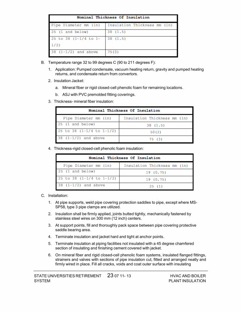
23 07 11- 13STATE UNIVERSITIES RETIREMENTSYSTEM
HVAC AND BOILERPLANT INSULATION
B. Temperature range 32 to 99 degrees C (90 to 211 degrees F):
1. Application: Pumped condensate, vacuum heating return, gravity and pumped heating returns, and condensate return from convertors.
2. Insulation Jacket:
a. Mineral fiber or rigid closed-cell phenolic foam for remaining locations.
b. ASJ with PVC premolded fitting coverings.
3. Thickness- mineral fiber insulation:
4. Thickness-rigid closed-cell phenolic foam insulation:
C. Installation:
1. At pipe supports, weld pipe covering protection saddles to pipe, except where MS- SP58, type 3 pipe clamps are utilized.
2. Insulation shall be firmly applied, joints butted tightly, mechanically fastened by stainless steel wires on 300 mm (12 inch) centers.
3. At support points, fill and thoroughly pack space between pipe covering protective saddle bearing area.
4. Terminate insulation and jacket hard and tight at anchor points.
5. Terminate insulation at piping facilities not insulated with a 45 degree chamfered section of insulating and finishing cement covered with jacket.
6. On mineral fiber and rigid closed-cell phenolic foam systems, insulated flanged fittings, strainers and valves with sections of pipe insulation cut, fitted and arranged neatly and firmly wired in place. Fill all cracks, voids and coat outer surface with insulating

23 07 11- 14STATE UNIVERSITIES RETIREMENTSYSTEM
HVAC AND BOILERPLANT INSULATION
cement. Install jacket. Provide similar construction on welded and threaded fittings on calcium silicate systems or use premolded fitting insulation.
7. On mineral fiber systems, insulate welded and threaded fittings more than 50 mm (2 inches) in diameter with compressed blanket insulation (minimum 2/1) and finish with jacket or PVC cover.
8. Insulate fittings 50 mm (2 inches) and smaller with mastic finishing material and cover with jacket.
9. Insulate valve bonnet up to valve side of bonnet flange to permit bonnet flange removal without disturbing insulation.
10. Install jacket smooth, tight and neatly finish all edges. Over wrap ASJ butt strips by 50 percent. Secure aluminum jacket with stainless steel bands 300 mm (12 inches) on center or aluminum screws on 200 mm (4 inch) centers.
11. Do not insulate basket removal flanges on strainers.
3.3 PIPE INSULATION SCHEDULE
A. Provide insulation for piping systems as scheduled below:

23 07 11- 15STATE UNIVERSITIES RETIREMENTSYSTEM
HVAC AND BOILERPLANT INSULATION
END OF SECTION 23 07 11

23 09 23- 1 STATE UNIVERSITIES RETIREMENTSYSTEM
DIRECT DIGITAL CONTROLSYSTEM FOR HVAC
SECTION 23 09 23 - DIRECT DIGITAL CONTROL SYSTEM FOR HVAC PART I - GENERAL 1.1 DESCRIPTION
A. This project shall include Direct Digital Controls (DDC) for all systems as noted below and in the drawings. This is an extension of the existing Schneider Electric I/A Series by Alpha Controls & Services.
1. Air handling units
2. Variable air volume units
3. Fan powered boxes
4. Boilers and associated pumps
5. Chiller and Chilled water pumps
6. Exhaust fans
7. Finned tube radiation
B. Provide (a) direct-digital control system(s) as indicated on the project documents, point list, interoperability tables, drawings and as described in these specifications. Include a complete and working direct-digital control system. Include all engineering, programming, controls and installation materials, installation labor, commissioning and start-up, training, final project documentation and warranty.
1. The direct-digital control system(s) shall consist of high-speed, peer-to-peer network of DDC controllers. The direct-digital control system(s) shall be native BACnet. All new controllers, devices and components shall be accessible using a Web browser interface and shall communicate exclusively using the ASHRAE Standard 135 BACnet communications protocol without the use of gateways, unless otherwise allowed by this Section of the technical specifications, specifically shown on the design drawings and specifically requested otherwise by the OWNER.
a. If used, gateways shall support the ASHRAE Standard 135 BACnet communications protocol.
2. The work administered by this Section of the technical specifications shall include all labor, materials, special tools, equipment, enclosures, power supplies, software, software licenses, Project specific software configurations and database entries, interfaces, wiring, tubing, installation, labeling, engineering, calibration, documentation, submittals, testing, verification, training services, permits and licenses, transportation, shipping, handling, administration, supervision, management, insurance, Warranty, specified services and items required for complete and fully functional Controls Systems.
3. The control systems shall be designed such that each mechanical system shall operate under stand-alone mode. The contractor administered by this Section of the technical specifications shall provide controllers for each mechanical system. In the event of a network communication failure, or the loss of any other controller, the control system shall continue to operate independently.
C. Some products are furnished but not installed by the contractor administered by this Section of the technical specifications. The contractor administered by this Section of the technical specifications shall formally coordinate in writing and receive from other

23 09 23- 2 STATE UNIVERSITIES RETIREMENTSYSTEM
DIRECT DIGITAL CONTROLSYSTEM FOR HVAC
contractors formal acknowledgements in writing prior to submission the installation of the products. These products include the following:
1. Control valves.
2. Sensor wells and sockets in piping.
D. The direct-digital control system shall start and stop equipment, move (position) damper
actuators and valve actuators, and vary speed of equipment to execute the mission of the control system. Use electricity as the motive force for all damper and valve actuators, unless use of pneumatics as motive force is not acceptable.
1.2 RELATED WORK
A. Section 23 21 13, Hydronic Piping.
B. Section 23 22 13, Steam and Condensate Heating Piping.
C. Section 23 31 00, HVAC Ducts and Casings.
D. Section 23 36 00, Air Terminal Units.
E. Section 23 74 13, Packaged, Outdoor, Central-Station Air-Handling Units.
F. Section 26 05 11, Requirements for Electrical Installations.
G. Section 26 05 19, Low-Voltage Electrical Power Conductors and Cables (600 Volts and Below).
H. Section 26 05 26, Grounding and Bonding for Electrical Systems.
I. Section 26 05 33, Raceway and Boxes for Electrical Systems.
J. Section 28 31 00, Fire Detection and Alarm.
1.3 DEFINITION
A. Algorithm: A logical procedure for solving a recurrent mathematical problem; A prescribed set of well-defined rules or processes for the solution of a problem in a finite number of steps.
B. Analog: A continuously varying signal value (e.g., temperature, current, velocity)
C. BACnet: A Data Communication Protocol for Building Automation and Control Networks , ANSI/ASHRAE Standard 135. This communications protocol allows diverse building automation devices to communicate data over and services over a network.
D. BACnet/IP: Annex J of Standard 135. It defines and allows for using a reserved UDP socket to transmit BACnet messages over IP networks. A BACnet/IP network is a collection of one or more IP sub-networks that share the same BACnet network number.
E. BACnet Internetwork: Two or more BACnet networks connected with routers. The two networks may sue different LAN technologies.
F. BACnet Network: One or more BACnet segments that have the same network address and are interconnected by bridges at the physical and data link layers.
G. BACnet Segment: One or more physical segments of BACnet devices on a BACnet network, connected at the physical layer by repeaters.
H. BACnet Broadcast Management Device (BBMD): A communications device which broadcasts BACnet messages to all BACnet/IP devices and other BBMDs connected to the same BACnet/IP network.

23 09 23- 3 STATE UNIVERSITIES RETIREMENTSYSTEM
DIRECT DIGITAL CONTROLSYSTEM FOR HVAC
I. BACnet Testing Laboratories (BTL). The organization responsible for testing products for compliance with the BACnet standard, operated under the direction of BACnet International.
J. Baud: It is a signal change in a communication link. One signal change can represent one or more bits of information depending on type of transmission scheme. Simple peripheral communication is normally one bit per Baud. (e.g., Baud rate = 78,000 Baud/sec is 78,000 bits/sec, if one signal change = 1 bit).
K. Binary: A two-state system where a high signal level represents an "ON" condition and an "OFF" condition is represented by a low signal level.
L. BMP or bmp: Suffix, computerized image file, used after the period in a DOS-based computer file to show that the file is an image stored as a series of pixels.
M. Bus Topology: A network topology that physically interconnects workstations and network devices in parallel on a network segment.
N. Control Unit (CU): Generic term for any controlling unit, stand-alone, microprocessor based, digital controller residing on secondary LAN or Primary LAN, used for local controls or global controls
O. Deadband: A temperature range over which no heating or cooling is supplied, i.e., 22-25 degrees C (72-78 degrees F), as opposed to a single point change over or overlap).
P. Device: a control system component that contains a BACnet Device Object and uses BACnet to communicate with other devices.
Q. Device Object: Every BACnet device requires one Device Object, whose properties represent the network visible properties of that device. Every Device Object requires a unique Object Identifier number on the BACnet internetwork. This number is often referred to as the device instance.
R. Device Profile: A specific group of services describing BACnet capabilities of a device, as defined in ASHRAE Standard 135-2008, Annex
S. Standard device profiles include BACnet Operator Workstations (BOWS), BACnet Building Controllers (B-BC), BACnet Advanced Application Controllers (B-AAC), BACnet Application Specific Controllers (B-ASC), BACnet Smart Actuator (B-SA), and BACnet Smart Sensor (B-SS). Each device used in new construction is required to have a PICS statement listing which service and BIBBs are supported by the device.
T. Diagnostic Program: A software test program, which is used to detect and report system or peripheral malfunctions and failures. Generally, this system is performed at the initial startup of the system.
U. Direct Digital Control (DDC): Microprocessor based control including Analog/Digital conversion and program logic. A control loop or subsystem in which digital and analog information is received and processed by a microprocessor, and digital control signals are generated based on control algorithms and transmitted to field devices in order to achieve a set of predefined conditions.
V. Distributed Control System: A system in which the processing of system data is decentralized and control decisions can and are made at the subsystem level. System operational programs and information are provided to the remote subsystems and status is reported back to the Engineering Control Center. Upon the loss of communication with the Engineering Control center, the subsystems shall be capable of operating in a stand-alone mode using the last best available data.
W. Download: The electronic transfer of programs and data files from a central computer or operation workstation with secondary memory devices to remote computers in a network (distributed) system.

23 09 23- 4 STATE UNIVERSITIES RETIREMENTSYSTEM
DIRECT DIGITAL CONTROLSYSTEM FOR HVAC
X. DXF: An AutoCAD 2-D graphics file format. Many CAD systems import and export the DXF format for graphics interchange.
Y. Electrical Control: A control circuit that operates on line or low voltage and uses a mechanical means, such as a temperature sensitive bimetal or bellows, to perform control functions, such as actuating a switch or positioning a potentiometer.
Z. Electronic Control: A control circuit that operates on low voltage and uses a solid-state components to amplify input signals and perform control functions, such as operating a relay or providing an output signal to position an actuator.
AA. Engineering Control Center (ECC): The centralized control point for the intelligent control network. The ECC comprises of personal computer and connected devices to form a single workstation.
BB. Ethernet: A trademark for a system for exchanging messages between computers on a local area network using coaxial, fiber optic, or twisted-pair cables.
CC.Firmware: Firmware is software programmed into read only memory (ROM) chips. Software may not be changed without physically altering the chip.
DD.Gateway: Communication hardware connecting two or more different protocols. It translates one protocol into equivalent concepts for the other protocol. In BACnet applications, a gateway has BACnet on one side and non-BACnet (usually proprietary) protocols on the other side.
EE. GIF: Abbreviation of Graphic interchange format.
FF. Graphic Program (GP): Program used to produce images of air handler systems, fans, chillers, pumps, and building spaces. These images can be animated and/or color-coded to indicate operation of the equipment.
GG. Graphic Sequence of Operation: It is a graphical representation of the sequence of operation, showing all inputs and output logical blocks.
HH.I/O Unit: The section of a digital control system through which information is received and transmitted. I/O refers to analog input (AI, digital input (DI), analog output (AO) and digital output (DO). Analog signals are continuous and represent information such as temperature, pressure, and flow rate, whereas digital signals convert electronic signals to digital pulses (values), represent information such as motor status, filter status, and on-off equipment.
II. I/P: a method for conveying and routing packets of information over LAN paths. User Datagram Protocol (UDP) conveys information to “sockets” without confirmation of receipt. Transmission Control Protocol (TCP) establishes "sessions", which have end-to-end confirmation and guaranteed sequence of delivery.
JJ. JPEG: A standardized image compression mechanism stands for Joint Photographic Experts Group, the original name of the committee that wrote the standard.
KK. Local Area Network (LAN): A communication bus that interconnects operator workstation and digital controllers for peer-to-peer communications, sharing resources and exchanging information.
LL. Network Repeater: A device that receives data packet from one network and rebroadcasts to another network. No routing information is added to the protocol.
MM. MS/TP: Master-slave/token-passing (ISO/IEC 8802, Part 3). It uses twistedpair wiring for relatively low speed and low cost communication.
NN.Native BACnet Device: A device that uses BACnet as its primary method of communication with other BACnet devices without intermediary gateways. A system that uses native BACnet devices at all levels is a native BACnet system

23 09 23- 5 STATE UNIVERSITIES RETIREMENTSYSTEM
DIRECT DIGITAL CONTROLSYSTEM FOR HVAC
OO. Network Number: A site-specific number assigned to each network segment to identify for routing. This network number shall be unique throughout the BACnet internetwork.
PP. Object: The concept of organizing BACnet information into standard components with various associated properties. Examples include analog input objects and binary output objects.
QQ. Object Identifier: An object property used to identify the object, including object type and instance. Object Identifiers shall be unique within a device.
RR.Object Properties: Attributes of an object. Examples include present value and high limit properties of an analog input object. Properties are defined in ASHRAE 135; some are optional and some are required. Objects are controlled by reading from and writing to object properties.
SS. Operating system (OS): Software, which controls the execution of computer application programs.
TT. PCX: File type for an image file. When photographs are scanned onto a personal computer they can be saved as PCX files and viewed or changed by a special application program as Photo Shop.
UU.Peripheral: Different components that make the control system function as one unit. Peripherals include monitor, printer, and I/O unit.
VV. Peer-to-Peer: A networking architecture that treats all network stations as equal partners- any device can initiate and respond to communication with other devices.
WW. PICS: Protocol Implementation Conformance Statement, describing the BACnet capabilities of a device. All BACnet devices have published PICS.
XX. PID: Proportional, integral, and derivative control, used to control modulating equipment to maintain a setpoint.
YY. Repeater: A network component that connects two or more physical segments at the physical layer.
ZZ. Router: a component that joins together two or more networks using different LAN technologies. Examples include joining a BACnet Ethernet LAN to a BACnet MS/TP LAN.
AAA. Sensors: devices measuring state points or flows, which are then transmitted back to the DDC system.
BBB. Thermostats : devices measuring temperatures, which are used in control of standalone or unitary systems and equipment not attached to the DDC system.
1.4 QUALITY ASSURANCE
A. Criteria:
1. Single Source Responsibility of subcontractor: The Contractor shall obtain hardware and software supplied under this Section and delegate the responsibility to a single source controls installation subcontractor. The controls subcontractor shall be responsible for the complete design, installation, and commissioning of the system. The controls subcontractor shall be in the business of design, installation and service of such building automation control systems similar in size and complexity.
2. Equipment and Materials: Equipment and materials shall be cataloged products of manufacturers regularly engaged in production and installation of HVAC control systems. Products shall be manufacturer’s latest standard design and have been tested and proven in actual use.
3. The controls subcontractor shall provide a list of no less than five similar projects which have building control systems as specified in this Section. These projects shall be on-

23 09 23- 6 STATE UNIVERSITIES RETIREMENTSYSTEM
DIRECT DIGITAL CONTROLSYSTEM FOR HVAC
line and functional such that the Owner’s representative would observe the control systems in full operation.
4. The controls subcontractor shall have in-place facility with technical staff, spare parts inventory for the next five (5) years, and necessary test and diagnostic equipment to support the control systems.
5. The controls subcontractor shall have minimum of three years’ experience in design and installation of building automation systems similar in performance to those specified in this Section. Provide evidence of experience by submitting resumes of the project manager, the local branch manager, project engineer, the application engineering staff, and the electronic technicians who would be involved with the supervision, the engineering, and the installation of the control systems. Training and experience of these personnel shall not be less than three years. Failure to disclose this information shall be a ground for disqualification of the supplier.
6. Provide a competent and experienced Project Manager employed by the Controls Contractor. The Project Manager shall be supported as necessary by other Contractor employees in order to provide professional engineering, technical and management service for the work. The Project Manager shall attend scheduled Project Meetings as required and shall be empowered to make technical, scheduling and related decisions on behalf of the Controls Contractor.
B. Codes and Standards:
1. All work shall conform to the applicable Codes and Standards.
2. Electronic equipment shall conform to the requirements of FCC Regulation, Part 15, Governing Radio Frequency Electromagnetic Interference, and be so labeled.
1.5 PERFORMANCE
A. The system shall conform to the following:

23 09 23- 7 STATE UNIVERSITIES RETIREMENTSYSTEM
DIRECT DIGITAL CONTROLSYSTEM FOR HVAC
1. Control stability and accuracy: Control sequences shall maintain measured variable at setpoint within the following tolerances:
2. Extent of direct digital control: control design shall allow for at least the points indicated on the points lists on the drawings.
1.6 WARRANTY
A. Labor and materials for control systems shall be warranted for a period of one year.
B. Control system failures during the warranty period shall be adjusted, repaired, or replaced at no cost or reduction in service to the owner. The system includes all computer equipment, transmission equipment, and all sensors and control devices.
1.7 SUBMITTALS
A. Submit shop drawings in accordance with Section 01 33 23, SHOP DRAWINGS, PRODUCT DATA, AND SAMPLES.
B. Manufacturer’s literature and data for all components including the following:
1. A wiring diagram for each type of input device and output device including DDC controllers, modems, repeaters, or other system components. Diagram shall show how the device is wired and powered, showing typical connections at the digital controllers and each power supply, as well as the device itself. Show for all field connected devices, such as control relays, motor starters, electric or electronic actuators, and temperature pressure, flow and humidity sensors and transmitters.
2. A diagram of each terminal strip, including digital controller terminal strips, terminal strip location, termination numbers and the associated point names.
3. Control dampers and control valves schedule, including the size and pressure drop.
4. Control air-supply components, and computations for sizing compressors, receivers and main air-piping, if pneumatic controls are furnished.
5. Catalog cut sheets of all equipment used. This includes, software (by manufacturer and by third parties), DDC controllers, panels, peripherals, and associated components, and auxiliary control devices such as sensors, actuators, and control dampers. When manufacturer’s cut sheets apply to a product series rather than a specific product, the

23 09 23- 8 STATE UNIVERSITIES RETIREMENTSYSTEM
DIRECT DIGITAL CONTROLSYSTEM FOR HVAC
data specifically applicable to the project shall be highlighted. Each submitted piece of literature and drawings shall clearly reference the specification and/or drawings that it supposed to represent.
6. Sequence of operations for each HVAC system and the associated control diagrams. Equipment and control labels shall correspond to those shown on the drawings.
7. Color prints of proposed graphics with a list of points for display.
8. Schematic wiring diagrams for all control, communication and power wiring.
9. An instrumentation list for each controlled system. Each element of the controlled system shall be listed in table format. The table shall show element name, type of device, manufacturer, model number, and product data sheet number.
10. Riser diagrams of wiring between central control unit and all control panels.
C. Product Certificates: Compliance with Article, QUALITY ASSURANCE.
D. Licenses: Provide licenses for all software residing on and used by the Controls Systems and transfer these licenses to the Owner prior to completion.
E. As Built Control Drawings:
1. Furnish three (3) copies of as-built drawings for each control system. The documents shall be submitted for approval prior to final completion.
F. Operation and Maintenance (O/M) Manuals):
1. Submit in accordance with Article, INSTRUCTIONS, in Specification Section 01 00 00, GENERAL REQUIREMENTS.
2. Include the following documentation:
a. General description and specifications for all components, including logging on/off, alarm handling, producing trend reports, overriding computer control, and changing set points and other variables.
b. Detailed illustrations of all the control systems specified for ease of maintenance and repair/replacement procedures, and complete calibration procedures.
c. One copy of the final version of all software provided including operating systems, programming language, operator workstation software, and graphics software.
d. Complete troubleshooting procedures and guidelines for all systems.
e. Complete operating instructions for all systems.
f. Recommended preventive maintenance procedures for all system components including a schedule of tasks for inspection, cleaning and calibration. Provide a list of recommended spare parts needed to minimize downtime.
g. Training Manuals: Submit the course outline and training material to the Owner for approval three (3) weeks prior to the training to Owner facility personnel. These persons shall be responsible for maintaining and the operation of the control systems, including programming. The Owner reserves the right to modify any or all of the course outline and training material.
h. Licenses, guaranty, and other pertaining documents for all equipment and systems.
1.8 INSTRUCTIONS
A. Instructions to Owner operations personnel: Perform in accordance with Article, INSTRUCTIONS, in Specification Section 01 00 00, GENERAL REQUIREMENTS, and as noted below. First Phase: Formal instructions to the Owner facilities personnel for a total of 8 hours, given in multiple training sessions (each no longer than four hours in length),

23 09 23- 9 STATE UNIVERSITIES RETIREMENTSYSTEM
DIRECT DIGITAL CONTROLSYSTEM FOR HVAC
conducted sometime between the completed installation and prior to the performance test period of the control system, at a time mutually agreeable to the Contractor and the Owner.
B. Second Phase: This phase of training shall comprise of on the job training during start-up, checkout period, and performance test period. Owner facilities personnel shall work with the Contractor’s installation and test personnel on a daily basis during start-up and checkout period. During the performance test period, controls subcontractor shall provide 8 hours of instructions, given in multiple training sessions (each no longer than four hours in length), to the Owner facilities personnel.
C. The O/M Manuals shall contain approved submittals as outlined in Article 1.7, SUBMITTALS. The Controls subcontractor shall review the manual contents with Owner facilities personnel during second phase of training.
D. Training shall be given by direct employees of the controls system subcontractor.
1.9 APPLICABLE PUBLICATIONS
A. The publications listed below form a part of this specification to the extent referenced. The publications are referenced in the text by the basic designation only.
B. American Society of Heating, Refrigerating, and Air-Conditioning Engineers (ASHRAE):
Standard 135-10.........BACNET Building Automation and Control Networks
C. American Society of Mechanical Engineers (ASME):
B16.18-01...............Cast Copper Alloy Solder Joint Pressure Fittings.
B16.22-01...............Wrought Copper and Copper Alloy Solder Joint Pressure Fittings.
D. American Society of Testing Materials (ASTM):
B32-08..................Standard Specification for Solder Metal
B88-09..................Standard Specifications for Seamless Copper Water Tube
B88M-09.................Standard Specification for Seamless Copper Water Tube (Metric)
B280-08.................Standard Specification for Seamless Copper Tube for Air-Conditioning and Refrigeration Field Service
D2737-03................Standard Specification for Polyethylene (PE) Plastic Tubing
E. Federal Communication Commission (FCC):
Rules and Regulations Title 47 Chapter 1-2001 Part 15: Radio Frequency Devices.
F. Institute of Electrical and Electronic Engineers (IEEE):
802.3-11................Information Technology-Telecommunications and Information Exchange between Systems-Local and Metropolitan Area Networks- Specific Requirements-Part 3: Carrier Sense Multiple Access with Collision Detection (CSMA/CD) Access method and Physical Layer Specifications
G. National Fire Protection Association (NFPA):
70-11...................National Electric Code
90A-09..................Standard for Installation of Air-Conditioning and Ventilation Systems
H. Underwriter Laboratories Inc (UL):
94-10...................Tests for Flammability of Plastic Materials for Parts and Devices and Appliances
294-10..................Access Control System Units 486A/486B-
10............Wire Connectors

23 09 23- 10STATE UNIVERSITIES RETIREMENTSYSTEM
DIRECT DIGITAL CONTROLSYSTEM FOR HVAC
555S-11.................Standard for Smoke Dampers
916-10..................Energy Management Equipment
1076-10.................Proprietary Burglar Alarm Units and Systems
PART 2 – PRODUCTS
2.1 ACCEPTABLE MANUFACTURER’S
A. Schneider Electric I/A Series by Alpha Controls & Services, LLC, no substitutions or exceptions shall be allowed. Contact: Jason Vogelbaugh at (217) 299-1379 or [email protected]
2.2 MATERIALS
A. Use new products that the manufacturer is currently manufacturing and that have been installed in a minimum of 25 installations.
2.3 CONTROLS SYSTEM ARCHITECTURE
A. General
1. The Controls Systems shall consist of multiple Nodes and associated equipment connected by industry standard digital and communication network arrangements.
2. The future ECC, building controllers and principal communications network equipment shall be standard products of recognized major manufacturers available through normal PC and computer vendor channels – not "Clones" assembled by a third-party subcontractor.
3. The networks shall, at minimum, comprise, as necessary, the following:
a. A future fixed ECC and a portable operator’s terminal.
b. Network computer processing, data storage and BACnet-compliant communication equipment including Servers and digital data processors.
c. BACnet-compliant routers, bridges, switches, hubs, modems, gateways, interfaces and similar communication equipment.
d. Active processing BACnet-compliant building controllers connected to other BACNet-compliant controllers together with their power supplies and associated equipment.
e. Addressable elements, sensors, transducers and end devices.
f. Third-party equipment interfaces and gateways as described and required by the Contract Documents.
g. Other components required for a complete and working Control Systems as specified.
B. The Specifications for the individual elements and component subsystems shall be minimum requirements and shall be augmented as necessary by the Contractor to achieve both compliance with all applicable codes, standards and to meet all requirements of the Contract Documents.
C. Network Architecture
1. The Controls communication network shall utilize BACnet communications protocol operating over a standard Ethernet LAN and operate at a minimum speed of 100 Mb/sec.
2. The networks shall utilize only copper and optical fiber communication media as appropriate and shall comply with applicable codes, ordinances and regulations.
23 09 23- 11STATE UNIVERSITIES RETIREMENTSYSTEM
DIRECT DIGITAL CONTROLSYSTEM FOR HVAC
3. All necessary telephone lines, ISDN lines and internet Service Provider services and connections shall be provided by the Owner.
D. Third Party Interfaces:
1. The contractor administered by this Section of the technical specifications shall include necessary hardware, equipment, software and programming to allow data communications between the controls systems and building systems supplied by other trades.
2. Other manufacturers and contractors supplying other associated systems and equipment shall provide their necessary hardware, software and start-up at their cost and shall cooperate fully with the contractor administered by this Section of the technical specifications in a timely manner and at their cost to ensure complete functional integration.
2.4 COMMUNICATION
A. Control products, communication media, connectors, repeaters, hubs, and routers shall comprise a BACnet internetwork. Controller and operator interface communication shall conform to ANSI/ASHRAE Standard 135-2008, BACnet.
1. The Data link / physical layer protocol (for communication) acceptable to the Owner throughout its facilities is Ethernet (ISO 8802-3) and BACnet/IP.
2. The MS/TP data link / physical layer protocol is acceptable to the Owner in any new BACnet network or sub-network throughout its facilities.
B. Each controller shall have a communication port for connection to an operator interface.
C. Project drawings indicate remote buildings or sites to be connected by a nominal 56,000 baud modem over voice-grade telephone lines. In each remote location a modem and field device connection shall allow communication with each controller on the internetwork as specified in Paragraph D.
D. Internetwork operator interface and value passing shall be transparent to internetwork architecture.
1. An operator interface connected to a controller shall allow the operator to interface with each internetwork controller as if directly connected. Controller information such as data, status, reports, system software, and custom programs shall be viewable and editable from each internetwork controller.
2. Inputs, outputs, and control variables used to integrate control strategies across multiple controllers shall be readable by each controller on the internetwork. Program and test all cross controller links required to execute specified control system operation. An authorized operator shall be able to edit crossc ontroller links by typing a standard object address.
E. System shall be expandable to at least twice the required input and output objects with additional controllers, associated devices, and wiring. Expansion shall not require operator interface hardware additions or software revisions.
F. Controllers with real-time clocks shall use the BACnet Time Synchronization service. The system shall automatically synchronize system clocks daily from an operator-designated device via the internetwork. The system shall automatically adjust for daylight savings and standard time as applicable.
2.5 BACNET DEVICES
A. All BACnet Devices – controllers, gateways, routers, actuators and sensors shall conform to BACnet Device Profiles and shall be BACnet Testing Laboratories (BTL) -Listed as conforming to those Device Profiles. Protocol Implementation Conformance Statements

23 09 23- 12STATE UNIVERSITIES RETIREMENTSYSTEM
DIRECT DIGITAL CONTROLSYSTEM FOR HVAC
(PICSs), describing the BACnet capabilities of the Devices shall be published and available of the Devices through links in the BTL website.
1. BACnet Building Controllers, historically referred to as NACs, shall conform to the BACnet B-BC Device Profile, and shall be BTL-Listed as conforming to the B-BC Device Profile. The Device’s PICS shall be submitted.
2. BACnet Advanced Application Controllers shall conform to the BACnet B-AAC Device Profile, and shall be BTL-Listed as conforming to the B-AAC Device Profile. The Device’s PICS shall be submitted.
3. BACnet Application Specific Controllers shall conform to the BACnet B-ASC Device Profile, and shall be BTL-Listed as conforming to theB-ASC Device Profile. The Device’s PICS shall be submitted.
4. BACnet Smart Actuators shall conform to the BACnet B-SA Device Profile, and shall be BTL-Listed as conforming to the B-SA Device Profile. The Device’s PICS shall be submitted.
5. BACnet Smart Sensors shall conform to the BACnet B-SS Device Profile, and shall be BTL-Listed as conforming to the B-SS Device Profile. The Device’s PICS shall be submitted.
6. BACnet routers and gateways shall conform to the BACnet B-OTH Device Profile, and shall be BTL-Listed as conforming to the B-OTH Device Profile. The Device’s PICS shall be submitted.
2.6 CONTROLLERS
A. General. Provide an adequate number of BTL-Listed B-BC building controllers and an adequate number of BTL-Listed B-AAC advanced application controllers to achieve the performance specified in the Part 1 Article on “System Performance.” Each of these controllers shall meet the following requirements.
1. The controller shall have sufficient memory to support its operating system, database, and programming requirements.
2. The building controller shall share data with the future ECC and the other networked building controllers. The advanced application controller shall share data with its building controller and the other networked advanced application controllers.
3. The operating system of the controller shall manage the input and output communication signals to allow distributed controllers to share real and virtual object information and allow for central monitoring and alarms.
4. Controllers that perform scheduling shall have a real-time clock.
5. The controller shall continually check the status of its processor and memory circuits. If an abnormal operation is detected, the controller shall:
a. Assume a predetermined failure mode, and generate an alarm notification.
6. The controller shall communicate with other BACnet devices on the internetwork using the BACnet Read (Execute and Initiate) and Write (Execute and Initiate) Property services.
7. Communication.
b. Each controller shall reside on a BACnet network using the ISO 8802-3 (Ethernet) Data Link/Physical layer protocol for its communications. Each building controller also shall perform BACnet routing if connected to a network of custom application and application specific controllers.
c. The controller shall provide a service communication port using BACnet Data Link/Physical layer protocol for connection to a portable operator’s terminal.

23 09 23- 13STATE UNIVERSITIES RETIREMENTSYSTEM
DIRECT DIGITAL CONTROLSYSTEM FOR HVAC
8. Keypad. A local keypad and display shall be provided for each controller. The keypad shall be provided for interrogating and editing data. Provide a system security password shall be available to prevent unauthorized use of the keypad and display.
9. Serviceability. Provide diagnostic LEDs for power, communication, and processor. All wiring connections shall be made to field removable, modular terminal strips or to a termination card connected by a ribbon cable.
10. Memory. The controller shall maintain all BIOS and programming information in the event of a power loss for at least 72 hours.
B. Provide BTL-Listed B-ASC application specific controllers for each piece of equipment for which they are constructed. Application specific controllers shall communicate with other BACnet devices on the internetwork using the BACnet Read (Execute) Property service.
1. Each B-ASC shall be capable of stand-alone operation and shall continue to provide control functions without being connected to the network.
2. Each B-ASC shall contain sufficient I/O capacity to control the target system.
3. Communication.
a. Each controller shall reside on a BACnet network using the ISO 8802-3 (Ethernet) Data Link/Physical layer protocol for its communications. Each building controller also shall perform BACnet routing if connected to a network of custom application and application specific controllers.
b. Each controller shall have a BACnet Data Link/Physical layer compatible connection for a laptop computer or a portable operator’s tool. This connection shall be extended to a space temperature sensor port where shown.
4. Serviceability. Provide diagnostic LEDs for power, communication, and processor. All wiring connections shall be made to field removable, modular terminal strips or to a termination card connected by a ribbon cable.
5. Memory. The application specific controller shall use nonvolatile memory and maintain all BIOS and programming information in the event of a power loss.
6. Immunity to power and noise. Controllers shall be able to operate at 90% to 110% of nominal voltage rating and shall perform an orderly shutdown below 80%. Operation shall be protected against electrical noise of 5-120 Hz and from keyed radios up to 5 W at 1 m (3 ft).
7. Transformer. Power supply for the ASC shall be rated at a minimum of 125% of ASC power consumption and shall be of the fused or current limiting type.
C. Direct Digital Controller Software
1. All controllers shall be capable of being programmed to utilize stored default values for assured fail-safe operation of critical processes. Default values shall be invoked upon sensor failure or, if the primary value is normally provided by the central or another CU, or by loss of bus communication. Individual application software packages shall be structured to assume a fail-safe condition upon loss of input sensors. Loss of an input sensor shall result in output of a sensor-failed message at the ECC. Each ACU and RCU shall have capability for local readouts of all functions. The UCUs shall be read remotely.
2. All DDC control loops shall be able to utilize any of the following control modes:
a. Two position (on-off, slow-fast) control.
b. Proportional control.
c. Proportional plus integral (PI) control.
23 09 23- 14STATE UNIVERSITIES RETIREMENTSYSTEM
DIRECT DIGITAL CONTROLSYSTEM FOR HVAC
d. Proportional plus integral plus derivative (PID) control. All PID programs shall automatically invoke integral wind up prevention routines whenever the controlled unit is off, under manual control of an automation system or time initiated program.
e. Automatic tuning of control loops.
3. System Security: Operator access shall be secured using individual password and operator’s name. Passwords shall restrict the operator to the level of object, applications, and system functions assigned to him. A minimum of six (6) levels of security for operator access shall be provided.
4. Application Software: The controllers shall provide the following programs as a minimum for the purpose of optimizing energy consumption while maintaining comfortable environment for occupants. All application software shall reside and run in the system digital controllers. Editing of the application shall occur at the future ECC or via a portable operator’s terminal, when it is necessary, to access directly the programmable unit.
f. Economizer: An economizer program shall be provided for air handling systems. This program shall control the position of air handler relief, return, and outdoors dampers, as applicable according to the drawings.
g. Night Setback/Morning Warm up Control: The system shall provide the ability to automatically adjust set points for this mode of operation.
h. Event Scheduling: Provide a comprehensive menu driven program to automatically start and stop designated points or a group of points according to a stored time. This program shall provide the capability to individually command a point or group of points. When points are assigned to one common load group it shall be possible to assign variable time advances/delays between each successive start or stop within that group. Scheduling shall be calendar based and advance schedules may be defined up to one year in advance. Advance schedule shall override the day-to- day schedule. The operator shall be able to define the following information:
(a) Time, day.
(b) Commands such as on, off, auto.
(c) Time delays between successive commands.
(d) Manual overriding of each schedule.
(e) Allow operator intervention.
i. Alarm Reporting: The operator shall be able to determine the action to be taken in the event of an alarm. Alarms shall be routed to the future ECC based on time and events. An alarm shall be able to start programs, login the event, print and display the messages. The system shall allow the operator to prioritize the alarms to minimize nuisance reporting and to speed operator’s response to critical alarms. A minimum of six (6) priority levels of alarms shall be provided for each point.
j. Remote Communications: The system shall have the ability to dial out in the event of an alarm to the future ECC and alpha-numeric pagers. The alarm message shall include the name of the calling location, the device that generated the alarm, and the alarm message itself. The operator shall be able to remotely access and operate the system using dial up communications. Remote access shall allow the operator to function the same as local access.
k. Maintenance Management (PM): The program shall monitor equipment status and generate maintenance messages based upon the operators defined equipment run time, starts, and/or calendar date limits. A preventative maintenance alarm shall be printed indicating maintenance requirements based on pre-defined run time. Each preventive message shall include point description, limit criteria and preventative

23 09 23- 15STATE UNIVERSITIES RETIREMENTSYSTEM
DIRECT DIGITAL CONTROLSYSTEM FOR HVAC
maintenance instruction assigned to that limit. A minimum of 480-character PM shall be provided for each component of units such as air handling units.
2.7 SENSORS (AIR, WATER AND STEAM)
A. Sensors’ measurements shall be read back to the DDC system, and shall be visible by the future ECC.
B. Temperature and Humidity Sensors shall be electronic, vibration and corrosion resistant for wall, immersion, and/or duct mounting. Provide all remote sensors as required for the systems.
1. Temperature Sensors: thermistor type for terminal units and Resistance Temperature Device (RTD) with an integral transmitter type for all other sensors.
a. Duct sensors shall be rigid or averaging type as shown on drawings. Averaging sensor shall be a minimum of 1 linear ft of sensing element for each sq ft of cooling coil face area.
b. Immersion sensors shall be provided with a separable well made of stainless steel or bronze material. Pressure rating of well is to be consistent with the system pressure in which it is to be installed.
c. Space sensors shall be equipped with in-space User set-point adjustment, override switch, numerical temperature display on sensor cover, and communication port. Match room thermostats. Provide a tooled-access cover.
(a) Public space sensor: set point adjustment shall be only through the future ECC or through the DDC system’s diagnostic device/laptop. Do not provide in-space User set-point adjustment.
d. Outdoor air temperature sensors shall have watertight inlet fittings and be shielded from direct sunlight.
e. Wire: Twisted, shielded-pair cable.
f. Output Signal: 4-20 ma.
2. Humidity Sensors: Bulk polymer sensing element type.
a. Duct and room sensors shall have a sensing range of 20 to 80 percent with accuracy of ± 3 to ・ 5 pe rc e nt R H, inc
b. Outdoor humidity sensors shall be furnished with element guard and mounting plate and have a sensing range of 0 to 100 percent RH.
c. 4-20 ma continuous output signal.
B. Static Pressure Sensors: Non-directional, temperature compensated.
1. 4-20 ma output signal.
2. 0 to 5 inches wg for duct static pressure range.
3. 0 to 0.25 inch wg for Building static pressure range.
C. Current Switches: Current operated switches shall be self-powered, solid state with adjustable trip current as well as status, power, and relay command status LED indication. The switches shall be selected to match the current of the application and output requirements of the DDC systems.
2.8 CONTROL CABLES
A. General:

23 09 23- 16STATE UNIVERSITIES RETIREMENTSYSTEM
DIRECT DIGITAL CONTROLSYSTEM FOR HVAC
1. Ground cable shields, drain conductors, and equipment to eliminate shock hazard and to minimize ground loops, common-mode returns noise pickup, cross talk, and other impairments. Comply with Sections 27 05 26 and 26 05 26.
2. Cable conductors to provide protection against induction in circuits. Crosstalk attenuation within the System shall be in excess of -80 dB throughout the frequency ranges specified.
3. Minimize the radiation of RF noise generated by the System equipment so as not to interfere with any audio, video, data, computer main distribution frame (MDF), telephone customer service unit (CSU), and electronic private branch exchange (EPBX) equipment the System may service.
4. The as-installed drawings shall identify each cable as labeled, used cable, and bad cable pairs.
5. Label system’s cables on each end. Test and certify cables in writing to the Owner before conducting proof-of-performance testing. Minimum cable test requirements are for impedance compliance, inductance, capacitance, signal level compliance, opens, shorts, cross talk, noise, and distortion, and split pairs on all cables in the frequency ranges used. Make available all cable installation and test records at demonstration to the Owner. All changes (e.g. used pair, failed pair) shall be posted in these records as the change occurs.
6. Power wiring shall not be run in conduit with communications trunk wiring or signal or control wiring operating at 100 volts or less.
B. Analogue control cabling shall be not less than No. 18 AWG solid, with thermoplastic insulated conductors as specified in Section 26 05 19.
C. Copper digital communication cable between the future ECC and the B-BC and B-AAC controllers shall be 100BASE-TX Ethernet, Category 5e or 6, not less than minimum 24 American Wire Gauge (AWG) solid, Shielded Twisted Pair (STP) or Unshielded Twisted Pair (UTP), with thermoplastic insulated conductors, enclosed in a thermoplastic outer jacket.
1. Other types of media commonly used within IEEE Std 802.3 LANs (e.g., 10Base-T and 10Base-2) shall be used only in cases to interconnect with existing media.
D. Optical digital communication fiber, if used, shall be Multimode or Singlemode fiber, 62.5/125 micron for multimode or 10/125 micron for singlemode micron with SC or ST connectors as specified in TIA-568-C.1. Terminations, patch panels, and other hardware shall be compatible with the specified fiber. Fiber-optic cable shall be suitable for use with the 100Base-FX or the 100Base-SX standard (as applicable) as defined in IEEE Std 802.3.
2.9 THERMOSTATS AND HUMIDISTATS
A. Room thermostats controlling unitary standalone heating and cooling devices not connected to the DDC system shall have three modes of operation (heating - null or dead band - cooling). Thermostats for other areas shall have capability of being adjusted to eliminate null or dead band. Wall mounted thermostats shall have manufacturer's recommendation finish, setpoint range and temperature display and external adjustment:
1. Electronic Thermostats: Solid-state, microprocessor based, programmable to daily, weekend, and holiday schedules.
a. Public Space Thermostat: Public space thermostat shall have a thermistor sensor and shall not have a visible means of set point adjustment. Adjustment shall be via the digital controller to which it is connected.
b. Battery replacement without program loss.

23 09 23- 17STATE UNIVERSITIES RETIREMENTSYSTEM
DIRECT DIGITAL CONTROLSYSTEM FOR HVAC
B. Freezestats shall have a minimum of 300 mm (one linear foot) of sensing element for each 0.093 square meter (one square foot) of coil area. A freezing condition at any increment of 300 mm (one foot) anywhere along the sensing element shall be sufficient to operate the thermostatic element. Freezestats shall be manually-reset.
2.10 FINAL CONTROL ELEMENTS AND OPERATORS
A. Fail Safe Operation: Control valves and dampers shall provide "fail safe" operation in either the normally open or normally closed position as required for freeze, moisture, and smoke or fire protection.
B. Spring Ranges: Range as required for system sequencing and to provide tight shut-off.
C. Power Operated Control Dampers (other than VAV Boxes): Factory fabricated, balanced type dampers. All modulating dampers shall be opposed blade type and gasketed. Blades for two-position, duct-mounted dampers shall be parallel, airfoil (streamlined) type for minimum noise generation and pressure drop.
1. Leakage: maximum leakage in closed position shall not exceed 7 L/S (15 CFMs) differential pressure for outside air and exhaust dampers and 200 L/S/ square meter (40 CFM/sq. ft.) at 50 mm (2 inches) differential pressure for other dampers.
2. Frame shall be galvanized steel channel with seals as required to meet leakage criteria.
3. Blades shall be galvanized steel or aluminum, 200 mm (8 inch) maximum width, with edges sealed as required.
4. Bearing shall be nylon, bronze sleeve or ball type.
5. Hardware shall be zinc-plated steel. Connected rods and linkage shall be non-slip. Working parts of joints shall be brass, bronze, nylon or stainless steel.
6. Maximum air velocity and pressure drop through free area the dampers:
a. Smoke damper in air handling unit: 305 meter per minute (1000 fpm).
b. Duct mounted damper: 600 meter per minute (2000 fpm).
c. Maximum static pressure loss: 50 Pascal (0.20 inches water gage).
D. Control Valves:
1. Valves shall be rated for a minimum of 150 percent of system operating pressure at the valve location but not less than 900 kPa (125 psig).
2. Valves 50 mm (2 inches) and smaller shall be bronze body with threaded or flare connections.
3. Valves 60 mm (2 1/2 inches) and larger shall be bronze or iron body with flanged connections.
4. Brass or bronze seats except for valves controlling media above 100 degrees C (210 degrees F), which shall have stainless steel seats.
5. Flow characteristics:
a. Three way modulating valves shall be globe pattern. Position versus flow relation shall be linear relation for steam or equal percentage for water flow control.
b. Two-way modulating valves shall be globe pattern. Position versus flow relation shall be linear for steam and equal percentage for water flow control.
c. Two-way 2-position valves shall be ball, gate or butterfly type.
6. Maximum pressure drop:
a. Two position steam control: 20 percent of inlet gauge pressure.
23 09 23- 18STATE UNIVERSITIES RETIREMENTSYSTEM
DIRECT DIGITAL CONTROLSYSTEM FOR HVAC
b. Modulating Steam Control: 80 percent of inlet gauge pressure (acoustic velocity limitation).
c. Modulating water flow control, greater of 3 meters (10 feet) of water or the pressure drop through the apparatus.
7. Two position water valves shall be line size.
E. Damper and Valve Operators and Relays:
1. Electric operator shall provide full modulating control of dampers and valves. A linkage and pushrod shall be furnished for mounting the actuator on the damper frame internally in the duct or externally in the duct or externally on the duct wall, or shall be furnished with a direct-coupled design. Metal parts shall be aluminum, mill finish galvanized steel, or zinc plated steel or stainless steel. Provide actuator heads which allow for electrical conduit attachment. The motors shall have sufficient closure torque to allow for complete closure of valve or damper under pressure. Provide multiple motors as required to achieve sufficient close-off torque.
a. Minimum valve close-off pressure shall be equal to the system pump’s dead-head pressure, minimum 50 psig for valves smaller than 4 inches.
2. Electronic damper operators: Metal parts shall be aluminum, mill finish galvanized steel, or zinc plated steel or stainless steel. Provide actuator heads which allow for electrical conduit attachment. The motors shall have sufficient closure torque to allow for complete closure of valve or damper under pressure. Provide multiple motors as required to achieve sufficient close-off torque.
b. VAV Box actuator shall be mounted on the damper axle or shall be of the air valve design, and shall provide complete modulating control of the damper. The motor shall have a closure torque of 35-inch pounds minimum with full torque applied at close off to attain minimum leakage.
3. See drawings for required control operation.
PART 3 – EXECUTION
3.1 INSTALLATION
A. General:
1. Examine project plans for control devices and equipment locations and report any discrepancies, conflicts, or omissions to COR for resolution before proceeding for installation.
2. Install equipment, piping, wiring /conduit parallel to or at right angles to building lines.
3. Install all equipment and piping in readily accessible locations. Do not run tubing and conduit concealed under insulation or inside ducts.
4. Mount control devices, tubing and conduit located on ducts and apparatus with external insulation on standoff support to avoid interference with insulation.
5. Provide sufficient slack and flexible connections to allow for vibration of piping and equipment.
6. Run tubing and wire connecting devices on or in control cabinets parallel with the sides of the cabinet neatly racked to permit tracing.
7. Install equipment level and plum.
B. Electrical Wiring Installation:
1. All wiring cabling shall be installed in conduit where inaccessible and in mechanical rooms in accordance with the National Electric Code and all local codes. Electrical Metallic Tubing (EMT) shall be installed.

23 09 23- 19STATE UNIVERSITIES RETIREMENTSYSTEM
DIRECT DIGITAL CONTROLSYSTEM FOR HVAC
2. For areas with lay-in ceilings and other accessible locations plenum cable using j-hooks and bridal rings in accordance with all applicable codes including the NEC shall be allowed. All work must be installed parallel and/or perpendicular to building structure.
3. Install all electrical work required for a fully functional system and not shown on electrical plans or required by electrical specifications. Where low voltage (less than 50 volt) power is required, provide suitable Class B transformers.
4. Install all system components in accordance with local Building Code and National Electric Code.
a. Splices: Splices in shielded and coaxial cables shall consist of terminations and the use of shielded cable couplers. Terminations shall be in accessible locations. Cables shall be harnessed with cable ties.
b. Equipment: Fit all equipment contained in cabinets or panels with service loops, each loop being at least 300 mm (12 inches) long. Equipment for fiber optics system shall be rack mounted, as applicable, in ventilated, self-supporting, code gauge steel enclosure. Cables shall be supported for minimum sag.
c. Cable Runs: Keep cable runs as short as possible. Allow extra length for connecting to the terminal board. Do not bend flexible coaxial cables in a radius less than ten times the cable outside diameter.
d. Use vinyl tape, sleeves, or grommets to protect cables from vibration at points where they pass around sharp corners, through walls, panel cabinets, or other opening that may cause damage to the cable.
5. Conceal cables, except in mechanical rooms and areas where other conduits and piping are exposed.
6. Permanently label or code each point of all field terminal strips to show the instrument or item served. Color-coded cable with cable diagrams may be used to accomplish cable identification.
7. Grounding: ground electrical systems per manufacturer’s written requirements for proper and safe operation.
C. Install Sensors and Controls:
1. Temperature Sensors:
a. Install all sensors and instrumentation according to manufacturer’s written instructions. Temperature sensor locations shall be readily accessible, permitting quick replacement and servicing of them without special skills and tools.
b. Calibrate sensors to accuracy specified, if not factory calibrated.
c. Use of sensors shall be limited to its duty, e.g., duct sensor shall not be used in lieu of room sensor.
d. Install room sensors permanently supported on wall frame. They shall be mounted at 48” to center above finished floor and in accordance with ADA requirements.
e. Mount sensors rigidly and adequately for the environment within which the sensor operates. Separate extended-bulb sensors form contact with metal casings and coils using insulated standoffs.
f. Sensors used in mixing plenum, and hot and cold decks shall be of the averaging of type. Averaging sensors shall be installed in a serpentine manner horizontally across duct. Each bend shall be supported with a capillary clip.
g. All pipe mounted temperature sensors shall be installed in wells.

23 09 23- 20STATE UNIVERSITIES RETIREMENTSYSTEM
DIRECT DIGITAL CONTROLSYSTEM FOR HVAC
h. All wires attached to sensors shall be air sealed in their conduits or in the wall to stop air transmitted from other areas affecting sensor reading.
i. Permanently mark terminal blocks for identification. Protect all circuits to avoid interruption of service due to short-circuiting or other conditions. Line-protect all wiring that comes from external sources to the site from lightning and static electricity.
2. Pressure Sensors:
a. Install duct static pressure sensor tips facing directly downstream of airflow.
b. Install high-pressure side of the differential switch between the pump discharge and the check valve.
c. Install snubbers and isolation valves on steam pressure sensing devices.
3. Actuators:
a. Mount and link damper and valve actuators according to manufacturer’s written instructions.
b. Check operation of damper/actuator combination to confirm that actuator modulates damper smoothly throughout stroke to both open and closed position.
c. Check operation of valve/actuator combination to confirm that actuator modulates valve smoothly in both open and closed position.
D. Installation of network:
1. Ethernet:
a. The network shall employ Ethernet LAN architecture, as defined by IEEE 802.3. The Network Interface shall be fully Internet Protocol (IP) compliant allowing connection to currently installed IEEE 802.3, Compliant Ethernet Networks.
b. The network shall directly support connectivity to a variety of cabling types. As a minimum provide the following connectivity: 100 Base TX (Category 5e cabling) for the communications between the ECC and the B-BC and the B-AAC controllers.
2. Third party interfaces: Contractor shall integrate real-time data from building systems by other trades and databases originating from other manufacturers as specified and required to make the system work as one system.
E. Installation of digital controllers and programming:
1. Provide a separate digital control panel for each major piece of equipment(i.e. air handling unit). Points used for control loop reset such as outdoor air, outdoor humidity, or space temperature could be located on any of the remote control units.
2. Provide sufficient internal memory for the specified control sequences and trend logging. There shall be a minimum of 25 percent of available memory free for future use.
3. System point names shall be modular in design, permitting easy operator interface without the use of a written point index.
4. Provide software programming for the applications intended for the systems specified, and adhere to the strategy algorithms provided.
5. Provide graphics for each piece of equipment and floor plan in the building. This includes each air handling unit, fan, and terminal unit. These graphics shall show all points dynamically as specified in the point list.
3.2 SYSTEM VALIDATION AND DEMONSTRATION

23 09 23- 21STATE UNIVERSITIES RETIREMENTSYSTEM
DIRECT DIGITAL CONTROLSYSTEM FOR HVAC
A. As part of final system acceptance, a system demonstration is required (see below). Prior to start of this demonstration, the contractor is to perform a complete validation of all aspects of the controls and instrumentation system.
B. Validation
C. Demonstration
1. System operation and calibration to be demonstrated by the installer in the presence of the Architect or Owner's representative on random samples of equipment as dictated by the Architect or Owner’s representative..
2. Demonstrate to authorities that all required safeties and life safety functions are fully functional and complete.
3. Make accessible, personnel to provide necessary adjustments and corrections to systems as directed by balancing agency.
4. The following witnessed demonstrations of field control equipment shall be included:
a. Observe HVAC systems in shut down condition. Check dampers and valves for normal position.
b. Test application software for its ability to communicate with digital controllers, operator workstation, and uploading and downloading of control programs.
c. Demonstrate the software ability to edit the control program offline.
d. Demonstrate reporting of alarm conditions for each alarm and ensure that these alarms are received at the assigned location, including operator workstations.
e. Demonstrate ability of software program to function for the intended applications- trend reports or change in status.
f. Demonstrate via graphed trends to show the sequence of operation is executed in correct manner, and that the HVAC systems operate properly through the complete sequence of operation, e.g., seasonal change, occupied/unoccupied mode, and warm-up condition.
g. Demonstrate hardware interlocks and safeties functions, and that the control systems perform the correct sequence of operation after power loss and resumption of power loss.
h. Prepare and deliver to the Owner graphed trends of all control loops to demonstrate that each control loop is stable and the set points are maintained.
i. Demonstrate that each control loop responds to set point adjustment and stabilizes within one (1) minute. Control loop trend data shall be instantaneous and the time between data points shall not be greater than one (1) minute.
END OF SECTION 23 09 23

STATE UNIVERSITIES RETIREMENT 23 21 13- 1 SYSTEM
HYDRONIC PIPING
SECTION 23 21 13 - HYDRONIC PIPING PART I - GENERAL 1.1 DESCRIPTION
A. Water piping to connect HVAC equipment, including the following:
1. Chilled water, heating hot water and drain piping.
1.2 RELATED WORK
A. Section 01 00 00, GENERAL REQUIREMENTS.
B. Section 01 33 23, SHOP DRAWINGS, PRODUCT DATA, and SAMPLES.
C. Section 07 12 00, BUILT-UP BITMUMINOUS WATERPROOFING, and Section 07 13 52, MODIFIED BITUMINOUS SHEET WATERPROOFING.
D. Section 23 05 11, COMMON WORK RESULTS FOR HVAC: General mechanical requirements and items, which are common to more than one section of Division 23.
E. Section 23 07 11, HVAC, and BOILER PLANT INSULATION: Piping insulation.
F. Section 23 25 00, HVAC WATER TREATMENT: Water treatment for open and closed systems.
G. Section 23 09 23, DIRECT-DIGITAL CONTROL SYSTEM FOR HVAC: Temperature and pressure sensors and valve operators.
1.3 QUALITY ASSURANCE
A. Section 23 05 11, COMMON WORK RESULTS FOR HVAC, which includes welding qualifications.
B. Submit prior to welding of steel piping a certificate of Welder’s certification. The certificate shall be current and not more than one year old.
C. All grooved joint couplings, fittings, valves, and specialties shall be the products of a single manufacturer. Grooving tools shall be the same manufacturer as the grooved components.
1. All castings used for coupling housings, fittings, or valve bodies, shall be date stamped for quality assurance and traceability.
1.4 SUBMITTALS
A. Product Data: Submit for each type of the products as listed below. Include component
sizes, rough‐in requirements, service sizes, and finishes. Include product description, model, and dimensions.
1. Pipe materials and fittings
2. Valves: Include flow and pressure drop curves based on manufacturer’s testing for calibrated balancing valves and automatic flow control valves.
3. Air control devices
4. Hydronic specialties
a. Shop Drawings: For all new piping systems submit layout drawings at ¼”=1’0”
scale in both hard‐copy and AutoCAD compatible format. Shop drawings shall include, but not be limited to:

STATE UNIVERSITIES RETIREMENT 23 21 13- 2 SYSTEM
HYDRONIC PIPING
b. Piping layout indicating sizes and locations
c. Elevations of piping
5. Slopes of horizontal piping
6. Wall and floor penetrations
7. Pressure rating for each service
8. Penetrations through fire‐rated and other partitions, floors, etc. 9. Equipment installation and connections based on the equipment being used on the
Project
10. Hangers and supports including multiple pipe hangers
11. Location of alignment guides, expansion joints, and anchors, including attachment to building structure
12. Shop drawings shall show other building and building system components for coordination purposes. Input from other installers shall be obtained. Any proposed changes to piping layout required for coordination purposed shall be indicated. Coordination items shown shall include but no be limited to:
13. Any pipe (e.g. sprinkler, plumbing pipes, roof drains, etc.) in vicinity of hydronic piping
a. Electrical equipment, duct banks, and conduit
b. Structural members, including structural members to which piping supports and anchors will be attached
B. Pipe Testing Submittals and Reports
1. Submit documentation of pipe pressure testing and submit test result reports within two weeks of testing.
2. Contractor shall be responsible for any corrective action required due to a failed pipe pressure test.
C. Manufacturer’s Installation Instruction: Submit manufacturer’s installation instructions for all manufactured products and assemblies required for this project.
D. Welding certificates
E. Operation and Maintenance Data: Include installation instruction, assembly views, lubrication instructions, and replacement parts list. For air control devices, hydronic
specialties, and special‐duty valves to include in emergency, operation, and maintenance manuals.
F. Final Record Drawings
1. During the construction process, the Contractor shall maintain a set of drawings showing the exact routing and location of piping systems being installed. The drawing shall be updated neatly by hand on a daily basis and account for routing modifications made in the field. Contractor shall use these drawing as a basis for generating the
project as‐built drawings.
G. As‐Built Drawings 1. Upon completion of project, Contractor shall furnish as‐built drawings showing in scale
the exact routing and locations of all newly installed piping systems.
1.5 APPLICABLE PUBLICATIONS
A. The publications listed below form a part of this specification to the extent referenced. The publications are referenced in the text by the basic designation only. American National
Standards Institute, Inc.

STATE UNIVERSITIES RETIREMENT 23 21 13- 3 SYSTEM
HYDRONIC PIPING
B. American Society of Mechanical Engineers/American National Standards Institute, Inc. (ASME/ANSI):
B1.20.1-83(R2006).......Pipe Threads, General Purpose (Inch)
B16.4-06................Gray Iron Threaded FittingsB16.18-01 Cast Copper Alloy Solder joint Pressure fittings
B16.23-02...............Cast Copper Alloy Solder joint Drainage fittings B40.100-
05..............Pressure Gauges and Gauge Attachments
C. C. American National Standards Institute, Inc./Fluid Controls Institute (ANSI/FCI):
70-2-2006...............Control Valve Seat Leakage
D. American Society of Mechanical Engineers (ASME):
B16.1-98................Cast Iron Pipe Flanges and Flanged Fittings
B16.3-2006..............Malleable Iron Threaded Fittings: Class 150 and 300 B16.4-
2006..............Gray Iron Threaded Fittings: (Class 125 and 250)
B16.5-2003..............Pipe Flanges and Flanged Fittings: NPS ½ through NPS 24 Metric/Inch Standard
B16.9-07................Factory Made Wrought Butt Welding Fittings B16.11-
05...............Forged Fittings, Socket Welding and Threaded B16.18-01...............Cast
Copper Alloy Solder Joint Pressure Fittings
B16.22-01...............Wrought Copper and Bronze Solder Joint Pressure Fittings. B16.24-
06...............Cast Copper Alloy Pipe Flanges and Flanged Fittings B16.39-
06...............Malleable Iron Threaded Pipe Unions
B16.42-06...............Ductile Iron Pipe Flanges and Flanged Fittings B31.1-
08................Power Piping
E. American Society for Testing and Materials (ASTM):
A47/A47M-99 (2004)......Ferritic Malleable Iron Castings
A53/A53M-07.............Standard Specification for Pipe, Steel, Black and Hot-Dipped, Zinc- Coated, Welded and Seamless
A106/A106M-08...........Standard Specification for Seamless Carbon Steel Pipe for High- Temperature Service
A126-04.................Standard Specification for Gray Iron Castings for Valves, Flanges, and Pipe Fittings
A183-03 ................ Standard Specification for Carbon Steel Track Bolts and Nuts
A216/A216M-08 .......... Standard Specification for Steel Castings, Carbon, Suitable for Fusion Welding, for High Temperature Service
A234/A234M-07 .......... Piping Fittings of Wrought Carbon Steel and Alloy Steel for Moderate and High Temperature Service
A307-07 ................ Standard Specification for Carbon Steel Bolts and Studs, 60,000 PSI Tensile Strength
A536-84 (2004) ......... Standard Specification for Ductile Iron Castings
A615/A615M-08 .......... Deformed and Plain Carbon Steel Bars for Concrete Reinforcement

STATE UNIVERSITIES RETIREMENT 23 21 13- 4 SYSTEM
HYDRONIC PIPING
A653/A 653M-08 ......... Steel Sheet, Zinc-Coated (Galvanized) or Zinc- Iron Alloy Coated (Galvannealed) By the Hot-Dip Process
B32-08 ................. Standard Specification for Solder Metal
B62-02 ................. Standard Specification for Composition Bronze or Ounce Metal Castings
B88-03 ................. Standard Specification for Seamless Copper Water Tube B209-
07 ................ Aluminum and Aluminum Alloy Sheet and Plate
C177-04 ............... Standard Test Method for Steady State Heat Flux Measurements and Thermal Transmission Properties by Means of the Guarded Hot Plate Apparatus
C533-07 ................ Calcium Silicate Block and Pipe Thermal Insulation C552-
07 ................ Cellular Glass Thermal Insulation
D3350-08 ............... Polyethylene Plastics Pipe and Fittings Materials
C591-08 ................ Unfaced Preformed Rigid Cellular Polyisocyanurate Thermal Insulation
F477-08 ................ Elastomeric Seals Gaskets) for Joining Plastic Pipe
F. American Water Works Association (AWWA):
C110-08.................Ductile Iron and Grey Iron Fittings for Water
C203-02.................Coal Tar Protective Coatings and Linings for Steel Water Pipe Lines Enamel and Tape Hot Applied
G. American Welding Society (AWS):
B2.1-02.................Standard Welding Procedure Specification
H. Copper Development Association, Inc. (CDA):
CDA A4015-06............Copper Tube Handbook
I. Expansion Joint Manufacturer’s Association, Inc. (EJMA):
EMJA-2003...............Expansion Joint Manufacturer’s Association Standards, Ninth Edition
J. Manufacturers Standardization Society (MSS) of the Valve and Fitting Industry, Inc.:
SP-67-02a...............Butterfly Valves
SP-70-06................Gray Iron Gate Valves, Flanged and Threaded Ends
SP-71-05................Gray Iron Swing Check Valves, Flanged and Threaded Ends SP-
80-08................Bronze Gate, Globe, Angle and Check Valves
SP-85-02................Cast Iron Globe and Angle Valves, Flanged and Threaded Ends
SP-110-96...............Ball Valves Threaded, Socket-Welding, Solder Joint, Grooved and Flared Ends
SP-125-00...............Gray Iron and Ductile Iron In-line, Spring Loaded, Center-Guided Check Valves
K. National Sanitation Foundation/American National Standards Institute, Inc. (NSF/ANSI):
14-06...................Plastic Piping System Components and Related Materials
50-2009a................Equipment for Swimming Pools, Spas, Hot Tubs and other Recreational Water Facilities – Evaluation criteria for materials, components, products, equipment and systems for use at recreational water facilities
61-2008.................Drinking Water System Components – Health Effects
STATE UNIVERSITIES RETIREMENT 23 21 13- 5 SYSTEM
HYDRONIC PIPING
L. Tubular Exchanger Manufacturers Association: TEMA 9th Edition, 2007
1.6 DELIVERY, STORAGE AND HANDLING
A. Protect new pipe interiors from moisture, construction debris and dust, and other foreign
materials with the use of plastic end caps/plugs on each end of pipe. Maintain end‐caps/plugs in place until piping is installed.
B. Store materials indoors, protected from the weather. Where exterior storage is necessary, elevate piping above grade and enclose with waterproof wrapping or cover.
C. Deliver and store valves in shipping containers with labeling in place.
D. Replace any piping or devices which are damaged during shipping or storage.
1.7 SPARE PARTS
A. For mechanical pressed sealed fittings provide tools required for each pipe size used at the facility.
1.8 WARRANTY
A. One year warranty on products and complete installation commencing at the time of Substantial Completion
PART 2 – PRODUCTS
2.1 PIPE AND EQUIPMENT SUPPORTS, PIPE SLEEVES, AND WALL AND CEILING PLATES
A. Provide in accordance with Section 23 05 11, COMMON WORK RESULTS FOR HVAC.
2.2 PIPE AND TUBING
A. Chilled Water, Heating Hot Water, and Vent Piping:
1. Steel: ASTM A53 Grade B, seamless or ERW, Schedule 40.
2. Copper water tube option: ASTM B88, Type K or L, hard drawn. Soft drawn tubing, 20 mm (3/4 inch) and larger, may be used for runouts routed under slab to floor mounted fan coil units.
B. Cooling Coil Condensate Drain Piping:
1. From air handling units: Copper water tube, ASTM B88, Type M.
2. From fan coil or other terminal units: Copper water tube, ASTM B88, Type L for runouts and Type M for mains.
C. Pipe supports, including insulation shields, for above ground piping: Section 23 05 11, COMMON WORK RESULTS FOR HVAC.
2.3 FLANGES, UNIONS AND COUPLINGS
A. Steel Pipe
1. Unions 2” and Smaller: ANSI/ASME B16.39 malleable iron unions for threaded pipe, ground joint, screwed bronze or brass to iron. Pressure class and joint type of union shall be equal to that specified for fittings of respective piping service.
2. Flanges 2 ½” and Larger: ANSI/ASME B16.5, forged steel, raised face, welding neck flanges. Pressure class and joint type of flange shall be equal to that specified for fittings of respective piping service.
3. Slip‐on flanges are not allowed. B. Flanges to match those on valves and equipment.
C. Flange Bolts and Nuts: ASME B18.2.1, carbon steel, unless otherwise indicated

STATE UNIVERSITIES RETIREMENT 23 21 13- 6 SYSTEM
HYDRONIC PIPING
D. Pipe‐Flange Gasket Materials 1. Suitable for chemical and thermal conditions of piping system contents.
2. ASME B16.21, nonmetallic, flat, asbestos free, 1/8” maximum thickness unless thickness or specific material is indicated.
a. Full‐Face Type: For flat‐face, Class 125, cast‐iron and cast‐bronze flanges
b. Narrow‐Face Type: For raised‐face, Class 250, cast‐iron and steel flanges 2.4 FITTINGS FOR STEEL PIPE
A. 50 mm (2 inches) and Smaller: Screwed or welded joints.
1. Butt welding: ASME B16.9 with same wall thickness as connecting piping.
2. Forged steel, socket welding or threaded: ASME B16.11.
3. Screwed: 150 pound malleable iron, ASME B16.3. 125 pound cast iron, ASME B16.4, may be used in lieu of malleable iron. Bushing reduction of a single pipe size, or use of close nipples, is not acceptable.
4. Unions: ASME B16.39.
5. Water hose connection adapter: Brass, pipe thread to 20 mm (3/4 inch) garden hose thread, with hose cap nut.
B. 65 mm (2-1/2 inches) and Larger: Welded or flanged joints. Contractor’s option: Grooved mechanical couplings and fittings are optional.
1. Butt welding fittings: ASME B16.9 with same wall thickness as connecting piping. Elbows shall be long radius type, unless otherwise noted.
2. Welding flanges and bolting: ASME B16.5:
a. Water service: Weld neck or slip-on, plain face, with 6 mm (1/8 inch) thick full face neoprene gasket suitable for 104 degrees C (220 degrees F).
(a) Contractor's option: Convoluted, cold formed 150 pound steel flanges, with teflon gaskets, may be used for water service.
b. Flange bolting: Carbon steel machine bolts or studs and nuts, ASTM A307, Grade B.
C. Welded Branch and Tap Connections: Forged steel weldolets, or branchlets and threadolets may be used for branch connections up to one pipe size smaller than the main. Forged steel half-couplings, ASME B16.11 may be used for drain, vent and gage connections.
D. Grooved Mechanical Pipe Couplings and Fittings (Contractor’s Option): Grooved Mechanical Pipe Couplings and Fittings may be used, with cut or roll grooved pipe, in water service up to 110 degrees C (230 degrees F) in lieu of welded, screwed or flanged connections. All joints shall be rigid type.
1. Grooved mechanical couplings: Malleable iron, ASTM A47 or ductile iron, ASTM A536, fabricated in two or more parts, securely held together by two or more track-head, square, or oval-neck bolts, ASTM A449 and A183.
2. Gaskets: Rubber product recommended by the coupling manufacturer for the intended service.
3. Grooved end fittings: Malleable iron, ASTM A47; ductile iron, ASTM A536; or steel, ASTM A53 or A106, designed to accept grooved mechanical couplings. Tap-in type branch connections are acceptable.
2.5 FITTINGS FOR COPPER TUBING

STATE UNIVERSITIES RETIREMENT 23 21 13- 7 SYSTEM
HYDRONIC PIPING
A. Joints:
1. Solder Joints: Joints shall be made up in accordance with recommended practices of the materials applied. Apply 95/5 tin and antimony on all copper piping.
2. Mechanically formed tee connection in water and drain piping: Form mechanically extracted collars in a continuous operation by drilling pilot hole and drawing out tube surface to form collar, having a height of not less than three times the thickness of tube wall. Adjustable collaring device shall insure proper tolerance and complete uniformity of the joint. Notch and dimple joining branch tube in a single process to provide free flow where the branch tube penetrates the fitting.
B. Bronze Flanges and Flanged Fittings: ASME B16.24.
C. Fittings: ANSI/ASME B16.18 cast copper or ANSI/ASME B16.22 solder wrought copper.
2.6 DIELECTRIC FITTINGS
A. Provide where copper tubing and ferrous metal pipe are joined.
B. 50 mm (2 inches) and Smaller: Threaded dielectric union, ASME B16.39.
C. 65 mm (2 1/2 inches) and Larger: Flange union with dielectric gasket and bolt sleeves, ASME B16.42.
D. Temperature Rating, 99 degrees C (210 degrees F).
E. Contractor’s option: On pipe sizes 2” and smaller, screwed end brass ball valves may be used in lieu of dielectric unions.
2.7 SCREWED JOINTS
A. Pipe Thread: ANSI B1.20.
B. Lubricant or Sealant: Oil and graphite or other compound approved for the intended service.
2.8 VALVES
A. Asbestos packing is not acceptable.
B. All valves of the same type shall be products of a single manufacturer.
C. Shut-Off Valves
1. Ball Valves (Pipe sizes 2” and smaller): MSS-SP 110, screwed or solder connections, brass or bronze body with chrome-plated ball with full port and Teflon seat at 2760 kPa (400 psig) working pressure rating. Provide stem extension to allow operation without interfering with pipe insulation.
a. Acceptable Manufacturers
(a) Apollo
(b) Crane
(c) Hammond
(d) Milwaukee
(e) Nibco
(f) Watts Regulator
2. Butterfly Valves (Pipe Sizes 2-1/2” and larger): Provide stem extension to allow 50 mm (2 inches) of pipe insulation without interfering with valve operation. MSS-SP 67, flange lug type or grooved end rated 1205 kPa (175 psig) working pressure at 93 degrees C (200 degrees F). Valves shall be ANSI Leakage Class VI and rated for bubble tight shut-off to full valve pressure rating. Valve shall be rated for dead end

STATE UNIVERSITIES RETIREMENT 23 21 13- 8 SYSTEM
HYDRONIC PIPING
service and bi-directional flow capability to full rated pressure. Not permitted for direct buried pipe applications.
a. Acceptable Manufacturers
(a) Bray
(b) DeZurik
(c) Keystone/Tyco
(d) Milwaukee
(e) Nibco
b. Body: Cast iron, ASTM A126, Class B. Malleable iron, ASTM A47 electro-plated, or ductile iron, ASTM A536, Grade 65-45-12 electro-plated.
c. Trim: Bronze, aluminum bronze, or 300 series stainless steel disc, bronze bearings, 316 stainless steel shaft and manufacturer's recommended resilient seat. Resilient seat shall be field replaceable, and fully line the body to completely isolate the body from the product. A phosphate coated steel shaft or stem is acceptable, if the stem is completely isolated from the product.
d. Actuators: Field interchangeable. Valves for balancing service shall have adjustable memory stop to limit open position.
(a) Valves 150 mm (6 inches) and smaller: Lever actuator with minimum of seven locking positions, except where chain wheel is required.
(b) Valves 200 mm (8 inches) and larger: Enclosed worm gear with handwheel, and where required, chain-wheel operator.
3. Gate Valves (Contractor’s Option in lieu of Ball or Butterfly Valves):
a. 50 mm (2 inches) and smaller: MSS-SP 80, Bronze, 1034 kPa (150 psig), wedge disc, rising stem, union bonnet.
b. 65 mm (2 1/2 inches) and larger: Flanged, outside screw and yoke. MSS-SP 70, iron body, bronze mounted, 861 kPa (125 psig) wedge disc.
D. Globe and Angle Valves
1. Acceptable Manufacturers
a. Crane
b. Hammond
c. Milwaukee
d. Nibco
2. Globe Valves
a. 50 mm (2 inches) and smaller: MSS-SP 80, bronze, 1034 kPa (150 lb.) Globe valves shall be union bonnet with metal plug type disc.
b. 65 mm (2 1/2 inches) and larger: 861 kPa (125 psig), flanged, iron body, bronze trim, MSS-SP-85 for globe valves.
3. Angle Valves:
a. 50 mm (2 inches) and smaller: MSS-SP 80, bronze, 1034 kPa (150 lb.) Angle valves shall be union bonnet with metal plug type disc.
b. 65 mm (2 1/2 inches) and larger: 861 kPa (125 psig), flanged, iron body, bronze trim, MSS-SP-85 for angle.

STATE UNIVERSITIES RETIREMENT 23 21 13- 9 SYSTEM
HYDRONIC PIPING
E. Check Valves
1. Swing Check Valves:
a. 50 mm (2 inches) and smaller: MSS-SP 80, bronze, 1034 kPa (150 lb.), 45 degree swing disc.
b. 65 mm (2 1/2 inches) and larger: 861 kPa (125 psig), flanged, iron body, bronze trim, MSS-SP-71 for check valves.
2. Non-Slam or Silent Check Valve: Spring loaded double disc swing check or internally guided flat disc lift type check for bubble tight shut-off. Provide where check valves are shown in chilled water and hot water piping. Check valves incorporating a balancingfeature may be used.
a. Body: MSS-SP 125 cast iron, ASTM A126, Class B, or steel, ASTM A216, Class WCB, or ductile iron, ASTM 536, flanged, grooved, or wafer type.
b. Seat, disc and spring: 18-8 stainless steel, or bronze, ASTM B62. Seats may be elastomer material.
F. Water Flow Balancing Valves: For flow regulation and shut-off. Valves shall be line size rather than reduced to control valve size.
1. Ball or Globe style valve.
2. A dual purpose flow balancing valve and adjustable flow meter, with bronze or cast iron body, calibrated position pointer, valved pressure taps or quick disconnects with integral check valves and preformed polyurethane insulating enclosure.
3. Provide a readout kit including flow meter, readout probes, hoses, flow charts or calculator, and carrying case.
G. Automatic Balancing Control Valves: Factory calibrated to maintain constant flow (plus or minus five percent) over system pressure fluctuations of at least 10 times the minimum required for control. Provide standard pressure taps and four sets of capacity charts. Valves shall be line size and be one of the following designs:
1. Gray iron (ASTM A126) or brass body rated 1205 kPa (175 psig) at 93 degrees C (200 degrees F), with stainless steel piston and spring.
2. Brass or ferrous body designed for 2067 kPa (300 psig) service at 121 degrees C (250 degrees F), with corrosion resistant, tamper proof, self-cleaning piston/spring assembly that is easily removable for inspection or replacement.
3. Combination assemblies containing ball type shut-off valves, unions, flow regulators, strainers with blowdown valves and pressure temperature ports shall be acceptable.
4. Provide a readout kit including flow meter, probes, hoses, flow charts and carrying case.
2.9 STRAINERS
A. Y Type.
1. Screens: Bronze, monel metal or 18-8 stainless steel, free area not less than 2-1/2 times pipe area, with perforations as follows: 1.1 mm (0.045 inch) diameter perforations for 100 mm (4 inches) and larger: 3.2 mm (0.125 inch) diameter perforations.
2.10 FLEXIBLE CONNECTORS FOR WATER SERVICE
A. Flanged Spool Connector:
1. Single arch or multiple arch type. Tube and cover shall be constructed of chlorobutyl elastomer with full faced integral flanges to provide a tight seal without gaskets.
STATE UNIVERSITIES RETIREMENT 23 21 13- 10SYSTEM
HYDRONIC PIPING
Connectors shall be internally reinforced with high strength synthetic fibers impregnated with rubber or synthetic compounds as recommended by connector manufacturer, and steel reinforcing rings.
2. Working pressures and temperatures shall be as follows:
a. Connector sizes 50 mm to 100 mm (2 inches to 4 inches), 1137 kPa (165psig) at 121 degrees C (250 degrees F).
b. Connector sizes 125 mm to 300 mm (5 inches to 12 inches), 965 kPa (140 psig) at 121 degrees C (250 degrees F).
3. Provide ductile iron retaining rings and control units.
B. Mechanical Pipe Couplings: See other fittings specified under Part 2, PRODUCTS.
2.11 EXPANSION JOINTS
A. Factory built devices, inserted in the pipe lines, designed to absorb axial cyclical pipe movement which results from thermal expansion and contraction. This includes factory- built or field-fabricated guides located along the pipe lines to restrain lateral pipe motion and direct the axial pipe movement into the expansion joints.
B. Manufacturing Quality Assurance: Conform to Expansion Joints Manufacturers Association Standards.
C. Bellows - Internally Pressurized Type:
1. Multiple corrugations of Type 304 or Type A240-321 stainless steel.
2. Internal stainless steel sleeve entire length of bellows.
3. External cast iron equalizing rings for services exceeding 340 kPa (50 psig).
4. Welded ends.
5. Design shall conform to standards of EJMA and ASME B31.1.
6. External tie rods designed to withstand pressure thrust force upon anchor failure if one or both anchors for the joint are at change in direction of pipeline.
7. Integral external cover.
D. Bellows - Externally Pressurized Type:
1. Multiple corrugations of Type 304 stainless steel.
2. Internal and external guide integral with joint.
3. Design for external pressurization of bellows to eliminate squirm.
4. Welded ends.
5. Conform to the standards of EJMA and ASME B31.1.
6. Threaded connection at bottom, 25 mm (one inch) minimum, for drain or drip point.
7. Integral external cover and internal sleeve.
E. Expansion Compensators:
1. Corrugated bellows, externally pressurized, stainless steel or bronze.
2. Internal guides and anti-torque devices.
3. Threaded ends.
4. External shroud.
5. Conform to standards of EJMA.

STATE UNIVERSITIES RETIREMENT 23 21 13- 11SYSTEM
HYDRONIC PIPING
F. Expansion Joint (Contractor’s Option): 2415 kPa (350 psig) maximum working pressure, steel pipe fitting consisting of telescoping body and slip-pipe sections, PTFE modified polyphenylene sulfide coated slide section, with grooved ends, suitable for axial end movement to 75 mm (3 inch).
G. Expansion Joint Identification: Provide stamped brass or stainless steel nameplate on each expansion joint listing the manufacturer, the allowable movement, flow direction, design pressure and temperature, date of manufacture, and identifying the expansion joint by the identification number on the contract drawings.
H. Guides: Provide factory-built guides along the pipe line to permit axial movement only and to restrain lateral and angular movement. Guides shall be designed to withstand a minimum of 15 percent of the axial force which will be imposed on the expansion joints and anchors. Field-built guides may be used if detailed on the contract drawings.
I. Supports: Provide saddle supports and frame or hangers for heat exchanger. Mounting height shall be adjusted to facilitate gravity return of steam condensate. Construct supports from steel, weld joints.
2.12 GAGES, PRESSURE
A. ASME B40.100, Accuracy Grade 1A, (pressure for water), initial mid-scale accuracy 1 percent of scale (Qualify grade), metal case, 115 mm (4-1/2 inches) in diameter, 6 mm (1/4 inch) NPT bottom connection, white dial with black graduations and pointer, clear glass window. Provide red "set hand" to indicate normal working pressure.
B. Provide brass lever handle union cock. Provide brass/bronze pressure snubber for gages in water service.
C. Range of Gages: Provide range equal to at least 130 percent of normal operating range.
2.13 PRESSURE/TEMPERATURE TEST PROVISIONS
A. Pete's Plug: 6 mm (1/4 inch) MPT by 75 mm (3 inches) long, brass body and cap, with retained safety cap, nordel self-closing valve cores, permanently installed in piping where shown, or in lieu of pressure gage test connections shown on the drawings.
2.14 THERMOMETERS
A. Mercury or organic liquid filled type, red or blue column, clear plastic window, with 150 mm (6 inch) brass stem, straight, fixed or adjustable angle as required for each in reading.
B. Case: Chrome plated brass or aluminum with enamel finish.
C. Scale: Not less than 225 mm (9 inches), range as described below, two degree graduations.
D. Separable Socket (Well): Brass, extension neck type to clear pipe insulation.
E. Scale ranges:
1. Chilled Water and Glycol-Water: 0-38 degrees C (32-100 degrees F).
2. Hot Water and Glycol-Water: -1 – 116 degrees C (30-240 degrees F).
2.15 FIRESTOPPING MATERIAL
A. Refer to Section 23 05 11, COMMON WORK RESULTS FOR HVAC.
2.16 ELECTRICAL HEAT TRACING SYSTEMS
A. Systems shall meet requirements of the National Electrical Code (NEC), Section 427.
B. Provide tracing for outdoor piping subject to freezing temperatures (Below 38 degrees F) as follows:
STATE UNIVERSITIES RETIREMENT 23 21 13- 12SYSTEM
HYDRONIC PIPING
1. Chilled water piping at units RTU-3, RTU-6, RTU-7 and all other areas exposed to the weather.
C. Heat tracing shall be provided to the extent shown on the drawings (Floor plans and Elevations). Heat tracing shall extend below grade to below the defined frost line.
D. Heating Cable: Flexible, parallel circuit construction consisting of a continuous self-limiting resistance, conductive inner core material between two parallel copper bus wires, designed for cut-to-length at the job site and for wrapping around valves and complex fittings. Selfregulation shall prevent overheating and burnouts even where the cable overlaps itself.
1. Provide end seals at ends of circuits. Wire at the ends of the circuits is not to be tied together.
2. Provide sufficient cable, as recommended by the manufacturer, to keep the pipe surface at 2.2 degrees C (36 degrees F) minimum during winter outdoor design temperature, but not less than the following:
a. 75 mm (3 inch) pipe and smaller with 25 mm (1 inch) thick insulation: 4 watts per foot of pipe.
b. 100 mm (4 inch)pipe and larger 38 mm (1-1/2 inch) thick insulation: 8 watts per feet of pipe.
E. Electrical Heating Tracing Accessories:
1. Power supply connection fitting and stainless steel mounting brackets. Provide stainless steel worm gear clamp to fasten bracket to pipe.
2. 13 mm (1/2 inch) wide fiberglass reinforced pressure sensitive cloth tape to fasten cable to pipe at 300 mm (12 inch) intervals.
3. Pipe surface temperature control thermostat: Cast aluminum, NEMA 4 (watertight) enclosure, 13 mm (1/2 inch) NPT conduit hub, SPST switch rated 20 amps at 480 volts AC, with capillary and copper bulb sensor. Set thermostat to maintain pipe surface temperature at not less than 1.1 degrees C (34 degrees F).
4. Signs: Manufacturer's standard (NEC Code), stamped "ELECTRIC TRACED" located on the insulation jacket at 3000 mm (10 feet) intervals along the pipe on alternating sides.
PART 3 – EXECUTION
3.1 INSTALLATION
A. Drawing plans, schematics, and diagrams indicate general location and arrangement of piping systems. Indicated piping locations and arrangements were used to size pipe and calculate friction loss, expansion, pump sizing, and other design considerations. Install piping as indicated unless deviations to layout are approved on Coordination Drawings.
B. Install piping in concealed locations, unless otherwise indicated and except in equipment rooms and service areas.
C. Install piping indicated to be exposed and piping in equipment rooms and service areas at right angles or parallel to building walls. Diagonal runs are prohibited unless specifically indicated otherwise.
D. Install piping to permit valve servicing.
E. Install piping at indicated slopes. Install piping at a uniform grade of 0.2 percent upward in direction of flow when not other slope is indicated on the drawings.
F. Install piping free of sags and bends.
G. Install fittings for changes in direction and branch connections.

STATE UNIVERSITIES RETIREMENT 23 21 13- 13SYSTEM
HYDRONIC PIPING
H. Install piping to allow application of insulation.
I. Install groups of pipes at common elevations, parallel to each other, spaced to permit applying insulation and servicing of valves.
J. Reduce pipe sizes using eccentric reducer fitting installed with level side up.
K. Install branch connections to mains using tee fittings in main pipe, with the branch
connected to the bottom of the main pipe. For up‐feed risers, connect the branch to the top of the main pipe.
1. The use of saddle or “cut‐in” connections is NOT allowed.
2. The use of T‐Drill connections is NOT allowed. L. The use of bullhead tee connections, where two opposite flows join to a common
perpendicular outlet, is NOT allowed.
M. Install piping to allow for expansion and contraction without stressing pipe, joints, or connected equipment.
N. Install pipe wells for temperature controls sensors and instrumentation. Coordinate with temperature controls contractor.
O. Pipe Joint Construction
1. Ream pipe and tube ends. Remove burrs. Bevel plain end ferrous pipe.
2. Remove scale, slag, dirt, and debris from inside and outside of pipe and fittings before assembly.
3. Soldered Joints: Apply ASTM B 813, water‐flushable flux, unless otherwise indicated, to tube end. Construct joints according to ASTM B 828 or CDA's “Copper Tube
Handbook,” using lead‐free solder alloy complying with ASTM B 32. 4. Brazed Joints: Construct joints according to AWS's “Brazing Handbook,”“Pipe and
Tube” Chapter, using copper‐phosphorus brazing filler metal complying with AWS A5.8.
5. Threaded Joints: Thread pipe with tapered pipe threads according to ASME B1.20.1. Cut threads full and clean using sharp dies. Ream threaded pipe ends to remove burrs and restore full ID. Join pipe fittings and valves as follows:
a. Apply appropriate tape or thread compound to external pipe threads unless dry seal threading is specified.
b. Damaged Threads: Do not use pipe or pipe fittings with threads that are corroded or damaged. Do not use pipe sections that have cracked or open welds.
6. Welded Joints: Construct joints according to AWS D10.12/D10.12M, using qualified processes and welding operators according to Part 1 “Quality Assurance” Article.
7. Flanged Joints: Select appropriate gasket material, size, type, and thickness for service application. Install gasket concentrically positioned. Use suitable lubricants on bolt threads.
8. Plastic Piping Solvent‐Cemented Joints: Clean and dry joining surfaces. Join pipe and fittings according to the following:
a. Comply with ASTM F 402 for safe‐handling practice of cleaners, primers, and solvent cements.
b. CPVC Piping: Join according to ASTM D 2846/D 2846M Appendix.
c. PVC Pressure Piping: Join ASTM D 1785 schedule number, PVC pipe and PVC
socket fittings according to ASTM D 2672. Join other‐thanschedule number PVC pipe and socket fittings according to ASTM D 2855.

STATE UNIVERSITIES RETIREMENT 23 21 13- 14SYSTEM
HYDRONIC PIPING
d. PVC Non‐Pressure Piping: Join according to ASTM D 2855. P. Coordination of mechanical work installation and access requirements:
1. Provide access where valves and fittings are not exposed. Coordinate size and location of access doors with Owner and General Contractor.
2. Where pipes are to be installed in partitions, furred out spaces and chases, obtain information as to their exact location and size and install work so as to be entirely concealed in allotted space.
3. Furnish advance information on locations and sizes of frames, boxes, sleeves and openings needed for work and also furnish information and shop drawings necessary to permit installation of other work without delay.
4. Where there is evidence that parts of Mechanical Work will interfere with other work, assist in working out space conditions and/or structure, and make necessary adjustments to accommodate work.
5. Mechanical Work installed before coordinating with other work so as to cause interference with other work to be changed to correct such condition without additional cost to Owner.
6. Install Mechanical work to permit removal (without damage to other parts) of coils, heat exchangers, pumps, fan shafts and wheels, belt guards, sheaves and drives and other parts requiring periodic replacement or maintenance.
7. Arrange pipes, ducts and equipment to permit ready access to valves, cocks, traps, starters, motors, dampers, control components and to clear the openings of swinging and overhead doors and of access panels.
8. Provide access panels in equipment, ducts and like items for inspection of interiors and proper maintenance.
Q. Appliances and equipment to be installed and connected with best engineering practices and in accordance with manufacturer’s instructions and recommendations. Piping, valves, connections and other like items recommended by manufacturer or as required for proper operation to be provided without additional cost to Owner.
R. In no case will any pipe, conduit or duct be installed where it is supported on or suspended from another pipe, conduit or duct.
S. Follow manufacturers’ directions in installation and operation of all equipment and materials.
T. Indirect waste lines, cooling coil drain pan lines, overflow pipes, relief valve discharge pipes, etc. shall have ends beveled at 45° angle to minimize splashing.
U. After completion or piping installation, clean, flush, and treat systems. Coordinate with chemical treatment requirements; refer to Division 23 Section 23 2500/ “Pipe Cleaning, Flushing, and Chemical Treatment.”
V. Valves
1. Examine valve interior for cleanliness. Clean or replace as required.
2. Remove special packing materials from valves.
3. Operate valves in positions from fully open to fully closed. Examine guides and seats made accessible by valve operation.
4. Install valves with stems upright or horizontal, not inverted.
5. Install valves in position to allow full movement and operation.
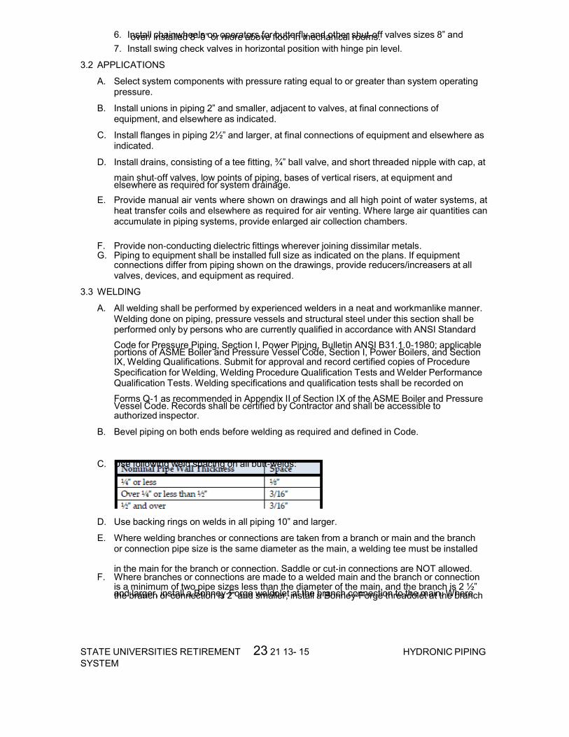
STATE UNIVERSITIES RETIREMENT 23 21 13- 15SYSTEM
HYDRONIC PIPING
6. Install chainwheels on operators for butterfly and other shut‐off valves sizes 8” and over/ installed 8’‐0” or more above floor in mechanical rooms. 7. Install swing check valves in horizontal position with hinge pin level.
3.2 APPLICATIONS
A. Select system components with pressure rating equal to or greater than system operating pressure.
B. Install unions in piping 2” and smaller, adjacent to valves, at final connections of equipment, and elsewhere as indicated.
C. Install flanges in piping 2½” and larger, at final connections of equipment and elsewhere as indicated.
D. Install drains, consisting of a tee fitting, ¾” ball valve, and short threaded nipple with cap, at
main shut‐off valves, low points of piping, bases of vertical risers, at equipment and elsewhere as required for system drainage.
E. Provide manual air vents where shown on drawings and all high point of water systems, at heat transfer coils and elsewhere as required for air venting. Where large air quantities can accumulate in piping systems, provide enlarged air collection chambers.
F. Provide non‐conducting dielectric fittings wherever joining dissimilar metals. G. Piping to equipment shall be installed full size as indicated on the plans. If equipment
connections differ from piping shown on the drawings, provide reducers/increasers at all valves, devices, and equipment as required.
3.3 WELDING
A. All welding shall be performed by experienced welders in a neat and workmanlike manner. Welding done on piping, pressure vessels and structural steel under this section shall be performed only by persons who are currently qualified in accordance with ANSI Standard
Code for Pressure Piping, Section I, Power Piping, Bulletin ANSI B31.1.0‐1980; applicable portions of ASME Boiler and Pressure Vessel Code, Section I, Power Boilers, and Section IX, Welding Qualifications. Submit for approval and record certified copies of Procedure Specification for Welding, Welding Procedure Qualification Tests and Welder Performance Qualification Tests. Welding specifications and qualification tests shall be recorded on
Forms Q‐1 as recommended in Appendix II of Section IX of the ASME Boiler and Pressure Vessel Code. Records shall be certified by Contractor and shall be accessible to authorized inspector.
B. Bevel piping on both ends before welding as required and defined in Code.
C. Use following weld spacing on all butt‐welds:
D. Use backing rings on welds in all piping 10” and larger.
E. Where welding branches or connections are taken from a branch or main and the branch or connection pipe size is the same diameter as the main, a welding tee must be installed
in the main for the branch or connection. Saddle or cut‐in connections are NOT allowed. F. Where branches or connections are made to a welded main and the branch or connection
is a minimum of two pipe sizes less than the diameter of the main, and the branch is 2 ½” and larger, install a Bonney‐Forge weldolet at the branch connection to the main. Where the branch or connection is 2” and smaller, install a Bonney‐Forge threadolet at the branch

STATE UNIVERSITIES RETIREMENT 23 21 13- 16SYSTEM
HYDRONIC PIPING
connection to the main. Screwed couplings, half couplings or screwed nipples welded to mains for screwed branches will not be permitted.
G. he method of attaching weldolet or threadolet units to the piping shall be in strict accordance with the ANSI Code for Pressure Piping, B31.1.
H. Before start of any welding, remove all corrosion and other foreign material from surface to be welded.
I. Welding shall be performed by either manual shielded metallic arc process or automatic submerged arc process. Use direct current exclusively.
J. Electrodes to be used with manual shielded metallic arc method shall conform to ASTM A‐233, Classification E‐6010. K. Size of electrodes, voltages, current, thickness, and number of passes or beads shall be in
accordance with provisions of previous paragraph.
L. After deposition, clean each layer of weld metal to remove all slab and scale by wire brushing or grinding, then chip where necessary to prepare for proper deposition of next layer.
M. Weld reinforcement shall be not less than 1/16” or more than ⅛” above normal surface of joined sections. Reinforcement shall be crowned at center and shall taper on each side to surface being joined. Exposed surface of weld shall present workmanlike appearance and shall be free of depressions below surface of joined members.
N. No welding of any kind shall be done when temperature of base metal is lower than 0°F. Material to be welded during freezing temperatures shall be made warm and dry before welding is started. Temperature of metal shall be “warm to hand”– or approximately 60°F.
O. All welders engaged in work performed under this Section shall have been qualified in accordance with test requirements of Section IX of the ASME Boiler and Pressure Vessel Code Each operator shall identify his production welds by marking his regularly assigned identification number or mark within 1” of weld. Contractor shall submit complete list of individual numbers of identifying marks and operator’s name, and a copy of each operator’s certificate.
3.4 TESTING
A. Furnish all labor, material, instruments, supplies and services and bear all costs for the accomplishment of tests herein specified. Correct all defects appearing under test and repeat the tests until no defects are disclosed; leave the equipment clean and ready for use.
B. Field test all piping before start‐up of systems. Tests of piping systems shall be conducted before connections to equipment are made and before piping is covered, buried or otherwise concealed.
C. Perform all tests other than herein specified which may be required by legal authorities or by agencies to whose requirements this work is to conform.
D. Furnish all necessary testing apparatus, make all temporary connections and perform all testing operations required, at no additional cost to Owner.
E. No work shall be insulated, painted, backfilled or concealed until authorized by Owner’s representative and/or the Engineer representative.
F. Inform Engineer and Owner’s representative 48 hours prior to when work is ready for test.
G. Systems found to have leaks shall be subjected to further tests when faulty joints have been repaired or replaced.
H. Prepare hydronic piping according to ASME B31.9 and as follows:

STATE UNIVERSITIES RETIREMENT 23 21 13- 17SYSTEM
HYDRONIC PIPING
1. Leave joints, including welds, uninsulated and exposed for examination during test.
2. Provide temporary restraints for expansion joints that cannot sustain reactions due to test pressure. If temporary restraints are impractical, isolate expansion joints from testing.
3. Flush hydronic piping systems with clean water; then remove and clean or replace strainer screens.
4. Isolate equipment from piping. If a valve is used to isolate equipment, its closure shall be capable of sealing against test pressure without damage to valve. Install blinds in flanged joints to isolate equipment.
5. Install safety valve, set at a pressure no more than one‐third higher than test pressure, to protect against damage by expanding liquid or other source of overpressure during test.
I. Perform the following tests on hydronic piping:
1. Use ambient temperature water as a testing medium unless there is risk of damage due to freezing. Another liquid that is safe for workers and compatible with piping may be used.
2. While filling system, use vents installed at high points of system to release air. Use drains installed at low points for complete draining of test liquid.
3. Isolate expansion tanks and determine that hydronic system is full of water.
4. Subject piping system to hydrostatic test pressure that is not less than 1.5 times the system's working pressure. Test pressure shall not exceed maximum pressure for any vessel, pump, valve, or other component in system under test. Verify that stress due to pressure at bottom of vertical runs does not exceed 90 percent of specified minimum yield strength or 1.7 times “SE” value in Appendix A in ASME B31.9, “Building Services Piping.”
5. After hydrostatic test pressure has been applied for at least 10 minutes, examine piping, joints, and connections for leakage. Eliminate leaks by tightening, repairing, or replacing components, and repeat hydrostatic test until there are no leaks.
6. Prepare written report of testing. Submit to Owner and Engineer.
J. Perform the following before operating the system:
1. Open manual valves fully.
2. Inspect pumps for proper rotation.
3. Set makeup pressure‐reducing valves for required system pressure. 4. Inspect air vents at high points of system and determine if all are installed and operating
freely (automatic type), or bleed air completely (manual type).
5. Set temperature controls so all coils are calling for full flow.
6. Inspect and set operating temperatures of hydronic equipment, such as boilers, chillers, and cooling towers, to specified values.
7. Verify lubrication of motors and bearings.
K. Test pressures shall be increased if necessary to comply with applicable codes.
3.5 FLUSHING AND CLEANING PIPING SYSTEMS
A. Water Piping: Clean systems as recommended by the suppliers of chemicals specified in Section 23 25 00, HVAC WATER TREATMENT.

STATE UNIVERSITIES RETIREMENT 23 21 13- 18SYSTEM
HYDRONIC PIPING
1. Initial flushing: Remove loose dirt, mill scale, metal chips, weld beads, rust, and like deleterious substances without damage to any system component. Provide temporary piping or hose to bypass coils, control valves, exchangers and other factory cleaned equipment unless acceptable means of protection are provided and subsequent inspection of hide-out areas takes place. Isolate or protect clean system components, including pumps and pressure vessels, and remove any component which may be damaged. Open all valves, drains, vents and strainers at all system levels. Remove plugs, caps, spool pieces, and components to facilitate early debris discharge from system. Sectionalize system to obtain debris carrying velocity of 1.8 m/S (6 feet per second), if possible. Connect dead-end supply and return headers as necessary. Flush bottoms of risers. Install temporary strainers where necessary to protect down-stream equipment. Supply and remove flushing water and drainage by various type hose, temporary and permanent piping and Contractor's booster pumps. Flush until clean as approved by the COR.
2. Cleaning: Using products supplied in Section 23 25 00, HVAC WATER TREATMENT, circulate systems at normal temperature to remove adherent organic soil, hydrocarbons, flux, pipe mill varnish, pipe joint compounds, iron oxide, and like deleterious substances not removed by flushing, without chemical or mechanical damage to any system component. Removal of tightly adherent mill scale is not required. Keep isolated equipment which is "clean" and where dead-end debris accumulation cannot occur. Sectionalize system if possible, to circulate at velocities not less than 1.8 m/S (6 feet per second). Circulate each section for not less than four hours. Blow-down all strainers, or remove and clean as frequently as necessary. Drain and prepare for final flushing.
3. Final Flushing: Return systems to conditions required by initial flushing after all cleaning solution has been displaced by clean make-up. Flush all dead ends and isolated clean equipment. Gently operate all valves to dislodge any debris in valve body by throttling velocity. Flush for not less than one hour.
3.6 WATER TREATMENT
A. Close and fill system as soon as possible after final flushing to minimize corrosion.
B. Charge systems with chemicals specified in Section 23 25 00, HVAC WATER TREATMENT.
C. Utilize this activity, by arrangement with the COR, for instructing Owner operating personnel.
3.7 ELECTRIC HEAT TRACING
A. Install tracing as recommended by the manufacturer.
B. Coordinate electrical connections.
3.8 OPERATING AND PERFORMANCE TEST AND INSTRUCTION
A. Refer to PART 3, Section 23 05 11, COMMON WORK RESULTS FOR HVAC.
B. Adjust red set hand on pressure gages to normal working pressure.
END OF SECTION 23 21 13

26 05 11- 1STATE UNIVERSITIES RETIREMENTSYSTEM
REQUIREMENTS FORELECTRICAL INSTALLATIONS
SECTION 26 05 11 - REQUIREMENTS FOR ELECTRICAL INSTALLATIONS
PART I - GENERAL
1.1 DESCRIPTION
A. This section applies to all sections of Division 26.
B. Furnish and install electrical systems, materials, equipment, and accessories in accordance with the specifications and drawings. Capacities and ratings of motors, conductors and cable, panelboards, and other items and arrangements for the specified items are shown on the drawings.
C. Coordinate temporary power with facility engineering. All temporary power installations shall be compliant with the NEC and shall be removed prior to project completion.
D. Conductor ampacities specified or shown on the drawings are based on copper conductors, with the conduit and raceways sized per NEC. Conductor size shall not be smaller than the size shown on the drawings, and shall be adjusted to a larger size as required to maintain a maximum 3% voltage drop from the source.
E. Aluminum conductors are prohibited.
1.2 MINIMUM REQUIREMENTS
A. The International Building Code (IBC), National Electrical Code (NEC), Underwriters Laboratories, Inc. (UL), and National Fire Protection Association (NFPA) codes and standards are the minimum requirements for materials and installation.
B. The drawings and specifications shall govern in those instances where requirements are greater than those stated in the above codes and standards.
1.3 TEST STANDARDS
A. All materials and equipment shall be listed, labeled, or certified by a Nationally Recognized Testing Laboratory (NRTL) to meet Underwriters Laboratories, Inc. (UL), standards where test standards have been established. Materials and equipment which are not covered by UL standards shall be accepted, providing that materials and equipment are listed, labeled, certified or otherwise determined to meet the safety requirements of a NRTL. Materials and equipment which no NRTL accepts, certifies, lists, labels, or determines to be safe, shall be considered if inspected or tested in accordance with national industrial standards, such as ANSI, NEMA, and NETA. Evidence of compliance shall include certified test reports and definitive shop drawings.
B. Definitions:
1. Listed: Materials and equipment included in a list published by an organization that is acceptable to the Authority Having Jurisdiction and concerned with evaluation of products or services, that maintains periodic inspection of production or listed materials and equipment or periodic evaluation of services, and whose listing states that the materials and equipment either meets appropriate designated standards or has been tested and found suitable for a specified purpose.
2. Labeled: Materials and equipment to which has been attached a label, symbol, or other identifying mark of an organization that is acceptable to the Authority Having Jurisdiction and concerned with product evaluation, that maintains periodic inspection of production of labeled materials and equipment, and by whose labeling the

26 05 11- 2STATE UNIVERSITIES RETIREMENTSYSTEM
REQUIREMENTS FORELECTRICAL INSTALLATIONS
manufacturer indicates compliance with appropriate standards or performance in a specified manner.
3. Certified: Materials and equipment which:
a. Have been tested and found by a NRTL to meet nationally recognized standards or to be safe for use in a specified manner.
b. Are periodically inspected by a NRTL.
c. Bear a label, tag, or other record of certification.
4. Nationally Recognized Testing Laboratory: Testing laboratory which is recognized and approved by the Secretary of Labor in accordance with OSHA regulations.
1.4 QUALIFICATIONS (PRODUCTS AND SERVICES)
A. Manufacturer’s Qualifications: The manufacturer shall regularly and currently produce, as one of the manufacturer's principal products, the materials and equipment specified for this project, and shall have manufactured the materials and equipment for at least three years.
B. Product Qualification:
1. Manufacturer's materials and equipment shall have been in satisfactory operation, on three installations of similar size and type as this project, for at least three years.
2. The Owner reserves the right to require the Contractor to submit a list of installations where the materials and equipment have been in operation before approval.
C. Service Qualifications: There shall be a permanent service organization maintained or trained by the manufacturer which shall render satisfactory service to this installation within four hours of receipt of notification that service is needed. Submit name and address of service organizations.
1.5 APPLICABLE PUBLICATIONS
A. Applicable publications listed in all Sections of Division 26 are the latest issue, unless otherwise noted.
B. Products specified in all sections of Division 26 shall comply with the applicable publications listed in each section.
1.6 MANUFACTURED PRODUCTS
A. Materials and equipment furnished shall be of current production by manufacturers regularly engaged in the manufacture of such items, and for which replacement parts shall be available.
B. When more than one unit of the same class or type of materials and equipment is required, such units shall be the product of a single manufacturer.
C. Equipment Assemblies and Components:
1. Components of an assembled unit need not be products of the same manufacturer.
2. Manufacturers of equipment assemblies, which include components made by others, shall assume complete responsibility for the final assembled unit.
3. Components shall be compatible with each other and with the total assembly for the intended service.
4. Constituent parts which are similar shall be the product of a single manufacturer.
D. Factory wiring and terminals shall be identified on the equipment being furnished and on all wiring diagrams.
E. When Factory Testing Is Specified:

26 05 11- 3STATE UNIVERSITIES RETIREMENTSYSTEM
REQUIREMENTS FORELECTRICAL INSTALLATIONS
1. The Owner shall have the option of witnessing factory tests. The Contractor shall notify the Owner through the COR a minimum of 15 working days prior to the manufacturer’s performing the factory tests.
2. Four copies of certified test reports shall be furnished to the COR two weeks prior to final inspection and not more than 90 days after completion of the tests.
3. When materials and equipment fail factory tests, and re-testing and re-inspection is required, the Contractor shall be liable for all additional expenses for the Owner to witness re-testing.
1.7 VARIATIONS FROM CONTRACT REQUIREMENTS
A. Where the Owner or the Contractor requests variations from the contract requirements, the connecting work and related components shall include, but not be limited to additions or changes to branch circuits, circuit protective devices, conduits, wire, feeders, controls, panels and installation methods.
1.8 MATERIALS AND EQUIPMENT PROTECTION
A. Materials and equipment shall be protected during shipment and storage against physical damage, vermin, dirt, corrosive substances, fumes, moisture, cold and rain.
1. Store materials and equipment indoors in clean dry space with uniform temperature to prevent condensation.
2. During installation, equipment shall be protected against entry of foreign matter, and be vacuum-cleaned both inside and outside before testing and operating. Compressed air shall not be used to clean equipment. Remove loose packing and flammable materials from inside equipment.
3. Damaged equipment shall be repaired or replaced, as determined by the COR.
4. Painted surfaces shall be protected with factory installed removable heavy kraft paper, sheet vinyl or equal.
5. Damaged paint on equipment shall be refinished with the same quality of paint and workmanship as used by the manufacturer so repaired areas are not obvious.
1.9 WORK PERFORMANCE
A. All electrical work shall comply with the requirements of NFPA 70 (NEC), NFPA 70B, NFPA 70E, OSHA Part 1910 subpart J – General Environmental Controls, OSHA Part 1910 subpart K – Medical and First Aid, and OSHA Part 1910 subpart S – Electrical, in addition to other references required by contract.
B. Job site safety and worker safety is the responsibility of the Contractor.
C. Electrical work shall be accomplished with all affected circuits or equipment de-energized. When an electrical outage cannot be accomplished in this manner for the required work, the following requirements are mandatory:
1. Electricians shall use full protective equipment (i.e., certified and tested insulating material to cover exposed energized electrical components, certified and tested insulated tools) while working on energized systems in accordance with NFPA 70E.
2. Before initiating any work, a job specific work plan shall be developed by the Contractor with a peer review conducted and documented by the COR and Owner staff. The work plan shall include procedures to be used on and near the live electrical equipment, barriers to be installed, safety equipment to be used, and exit pathways.
3. Work on energized circuits or equipment cannot begin until prior written approval is obtained from the COR.

26 05 11- 4STATE UNIVERSITIES RETIREMENTSYSTEM
REQUIREMENTS FORELECTRICAL INSTALLATIONS
D. For work that affects existing electrical systems, arrange, phase, and perform work to assure minimal interference with normal functioning of the facility. Refer to Article OPERATIONS AND STORAGE AREAS under Section 01 00 00, GENERAL REQUIREMENTS.
E. New work shall be installed and connected to existing work neatly, safely and professionally. Disturbed or damaged work shall be replaced or repaired to its prior conditions, as required by Section 01 00 00, GENERAL REQUIREMENTS.
F. Coordinate location of equipment and conduit with other trades to minimize interference.
1.10 EQUIPMENT INSTALLATION AND REQUIREMENTS
A. Equipment location shall be as close as practical to locations shown on the drawings.
B. Working clearances shall not be less than specified in the NEC.
C. Inaccessible Equipment:
1. Where the Owner determines that the Contractor has installed equipment not readily accessible for operation and maintenance, the equipment shall be removed and reinstalled as directed at no additional cost to the Owner.
2. "Readily accessible” is defined as being capable of being reached quickly for operation, maintenance, or inspections without the use of ladders, or without climbing or crawling under or over obstacles such as, but not limited to, motors, pumps, belt guards, transformers, piping, ductwork, conduit and raceways.
1.11 EQUIPMENT IDENTIFICATION
A. In addition to the requirements of the NEC, install an identification sign which clearly indicates information required for use and maintenance of items such as panelboards, cabinets, motor controllers, fused and non-fused safety switches, separately enclosed circuit breakers, individual breakers and controllers in switchboards, switchgear and motor control assemblies, control devices and other significant equipment.
B. Identification signs for Normal Power System equipment shall be laminated black phenolic resin with a white core with engraved lettering. Identification signs for Essential Electrical System (EES) equipment, as defined in the NEC, shall be laminated red phenolic resin with a white core with engraved lettering. Lettering shall be a minimum of 12 mm (1/2 inch) high. Identification signs shall indicate equipment designation, rated bus amperage, voltage, number of phases, number of wires, and type of EES power branch as applicable. Secure nameplates with stainless steel screws.
C. Install adhesive arc flash warning labels on all equipment as required by NFPA 70E. Label shall indicate the arc hazard boundary (inches), working distance (inches), arc flash incident energy at the working distance (calories/cm2), required PPE category and description including the glove rating, voltage rating of the equipment, limited approach distance (inches), restricted approach distance (inches), prohibited approach distance (inches), equipment/bus name, date prepared, and manufacturer name and address.
1.12 SUBMITTALS
A. Submit to the COR in accordance with Section 01 33 23, SHOP DRAWINGS, PRODUCT DATA, AND SAMPLES.
B. The Owner's approval shall be obtained for all materials and equipment before delivery to the job site. Delivery, storage or installation of materials and equipment which has not had prior approval shall not be permitted.
C. All submittals shall include adequate descriptive literature, catalog cuts, shop drawings, test reports, certifications, samples, and other data necessary for the Owner to ascertain that the proposed materials and equipment comply with drawing and specification

26 05 11- 5STATE UNIVERSITIES RETIREMENTSYSTEM
REQUIREMENTS FORELECTRICAL INSTALLATIONS
requirements. Catalog cuts submitted for approval shall be legible and clearly identify specific materials and equipment being submitted.
D. Submittals for individual systems and equipment assemblies which consist of more than one item or component shall be made for the system or assembly as a whole. Partial submittals shall not be considered for approval.
1. Mark the submittals, "SUBMITTED UNDER SECTION ".
2. Submittals shall be marked to show specification reference including the section and paragraph numbers.
3. Submit each section separately.
E. The submittals shall include the following:
1. Information that confirms compliance with contract requirements. Include the manufacturer's name, model or catalog numbers, catalog information, technical data sheets, shop drawings, manuals, pictures, nameplate data, and test reports as required. Where multiple items or catalog numbers, including accessories, appear on submittal documents, clearly identify (by circle, underline, boxing, and strike-out) which items are specifically being provided for this project.
2. Elementary and interconnection wiring diagrams for communication and signal systems, control systems, and equipment assemblies. All terminal points and wiring shall be identified on wiring diagrams.
3. Parts list which shall include information for replacement parts and ordering instructions, as recommended by the equipment manufacturer.
F. Maintenance and Operation Manuals:
1. Submit as required for systems and equipment specified in the technical sections. Furnish in hardcover binders or an approved equivalent. In addition to providing the binder, provide all information in digital format on a CD ROM. For panel schedules, provide a digitally editable file in .xls format.
2. Inscribe the following identification on the cover: the words "MAINTENANCE AND OPERATION MANUAL," the name and location of the system, material, equipment, building, name of Contractor, and contract name and number. Include in the manual the names, addresses, and telephone numbers of each subcontractor installing the system or equipment and the local representatives for the material or equipment.
3. Provide a table of contents and assemble the manual to conform to the table of contents, with tab sheets placed before instructions covering the subject. The instructions shall be legible and easily read, with large sheets of drawings folded in.
4. The manuals shall include:
a. Internal and interconnecting wiring and control diagrams with data to explain detailed operation and control of the equipment.
b. A control sequence describing start-up, operation, and shutdown.
c. Description of the function of each principal item of equipment.
d. Installation instructions.
e. Safety precautions for operation and maintenance.
f. Diagrams and illustrations.
g. Periodic maintenance and testing procedures and frequencies, including replacement parts numbers.
h. Performance data.

26 05 11- 6STATE UNIVERSITIES RETIREMENTSYSTEM
REQUIREMENTS FORELECTRICAL INSTALLATIONS
i. Pictorial "exploded" parts list with part numbers. Emphasis shall be placed on the use of special tools and instruments. The list shall indicate sources of supply, recommended spare and replacement parts, and name of servicing organization.
j. List of factory approved or qualified permanent servicing organizations for equipment repair and periodic testing and maintenance, including addresses and factory certification qualifications.
G. Approvals shall be based on complete submission of shop drawings, manuals, test reports, certifications, and samples as applicable.
H. After approval and prior to installation, furnish the COR with one sample of each of the following:
1. A minimum 300 mm (12 inches) length of each type and size of wire and cable along with the tag from the coils or reels from which the sample was taken. The length of the sample shall be sufficient to show all markings provided by the manufacturer.
2. Each type of conduit coupling, bushing, and termination fitting.
3. Conduit hangers, clamps, and supports.
4. Each type of receptacle, toggle switch, lighting control sensor, manual motor starter, device wall plate, engraved nameplate, wire and cable splicing and terminating material.
1.13 SINGULAR NUMBER
A. Where any device or part of equipment is referred to in these specifications in the singular number (e.g., "the switch"), this reference shall be deemed to apply to as many such devices as are required to complete the installation as shown on the drawings.
1.14 ACCEPTANCE CHECKS AND TESTS
A. The Contractor shall furnish the instruments, materials, and labor for tests.
B. Where systems are comprised of components specified in more than one section of Division 26, the Contractor shall coordinate the installation, testing, and adjustment of all components between various manufacturer’s representatives and technicians so that a complete, functional, and operational system is delivered to the Owner.
C. When test results indicate any defects, the Contractor shall repair or replace the defective materials or equipment, and repeat the tests. Repair, replacement, and retesting shall be accomplished at no additional cost to the Owner.
1.15 WARRANTY
A. All work performed and all equipment and material furnished under this Division shall be free from defects and shall remain so for a period of one year from the date of acceptance of the entire installation by the Contracting Officer for the Owner.
1.16 INSTRUCTION
A. Instruction to designated Owner personnel shall be provided for the particular equipment or system as required in each associated technical specification section.
B. Furnish the services of competent instructors to give full instruction in the adjustment, operation, and maintenance of the specified equipment and system, including pertinent safety requirements. Instructors shall be thoroughly familiar with all aspects of the installation, and shall be trained in operating theory as well as practical operation and maintenance procedures.
C. A training schedule shall be developed and submitted by the Contractor and approved by the COR at least 30 days prior to the planned training.

26 05 11- 7STATE UNIVERSITIES RETIREMENTSYSTEM
REQUIREMENTS FORELECTRICAL INSTALLATIONS
PART 2 – PRODUCTS
PART 3 – EXECUTION
END OF SECTION 26 05 11
26 05 19- 1STATE UNIVERSITIES RETIREMENTSYSTEM
LOW-VOLTAGE ELECTRICALPOWER CONDUCTORS
AND CABLES
SECTION 26 05 19 - LOW-VOLTAGE ELECTRICAL POWER CONDUCTORS AND CABLES PART I - GENERAL 1.1 DESCRIPTION
A. This section specifies the furnishing, installation, connection, and testing of the electrical conductors and cables for use in electrical systems rated 600 V and below, indicated as cable(s), conductor(s), wire, or wiring in this section.
1.2 1.2 RELATED WORK
A. Section 07 84 00, FIRESTOPPING: Sealing around penetrations to maintain the integrity of fire-resistant rated construction.
B. Section 26 05 11, REQUIREMENTS FOR ELECTRICAL INSTALLATIONS: Requirements that apply to all sections of Division 26.
C. Section 26 05 26, GROUNDING AND BONDING FOR ELECTRICAL SYSTEMS: Requirements for personnel safety and to provide a low impedance path for possible ground fault currents.
D. Section 26 05 33, RACEWAY AND BOXES FOR ELECTRICAL SYSTEMS: Conduits for conductors and cables.
1.3 QUALITY ASSURANCE
A. Refer to Paragraph, QUALIFICATIONS (PRODUCTS AND SERVICES), in Section 26 05 11, REQUIREMENTS FOR ELECTRICAL INSTALLATIONS.
B. All power conductors shall be new. Do not reuse existing conductors.
1.4 SUBMITTALS
A. Submit the following in accordance with Section 26 05 11, REQUIREMENTS FOR ELECTRICAL INSTALLATIONS.
1. Shop Drawings:
a. Submit sufficient information to demonstrate compliance with drawings and specifications.
b. Submit the following data for approval:
(a) Electrical ratings and insulation type for each conductor and cable.
(b) Splicing materials and pulling lubricant.
2. Certifications: Two weeks prior to final inspection, submit the following.
a. Certification by the Contractor that the conductors and cables have been properly installed, adjusted, and tested.
1.5 1.5 APPLICABLE PUBLICATIONS
A. Publications listed below (including amendments, addenda, revisions, supplements and errata) form a part of this specification to the extent referenced. Publications are reference in the text by designation only.
B. American Society of Testing Material (ASTM):
D2301-10................Standard Specification for Vinyl Chloride Plastic Pressure-Sensitive Electrical Insulating Tape

26 05 19- 2STATE UNIVERSITIES RETIREMENTSYSTEM
LOW-VOLTAGE ELECTRICALPOWER CONDUCTORS
AND CABLES
D2304-10................Test Method for Thermal Endurance of Rigid Electrical Insulating Materials
D3005-10................Low-Temperature Resistant Vinyl Chloride Plastic Pressure-Sensitive Electrical Insulating Tape
C. National Electrical Manufacturers Association (NEMA):
WC 70-09................Power Cables Rated 2000 Volts or Less for the Distribution of Electrical Energy
D. National Fire Protection Association (NFPA):
70-11...................National Electrical Code (NEC)
E. Underwriters Laboratories, Inc. (UL):
44-10...................Thermoset-Insulated Wires and Cables
83-08...................Thermoplastic-Insulated Wires and Cables
467-07..................Grounding and Bonding Equipment
486A-486B-03............Wire Connectors
486C-04.................Splicing Wire Connectors
486D-05.................Sealed Wire Connector Systems
486E-09.................Equipment Wiring Terminals for Use with Aluminum and/or Copper Conductors
493-07..................Thermoplastic-Insulated Underground Feeder and Branch Circuit Cables
514B-04.................Conduit, Tubing, and Cable Fittings
PART 2 – PRODUCTS
2.1 CONDUCTORS AND CABLES
A. Conductors and cables shall be in accordance with NEMA, UL, as specified herein, and as shown on the drawings.
B. All conductors shall be copper.
C. Single Conductor and Cable:
1. No. 12 AWG: Minimum size, except where smaller sizes are specified herein or shown on the drawings.
2. No. 8 AWG and larger: Stranded.
3. No. 10 AWG and smaller: Solid; except shall be stranded for final connection to motors, transformers, and vibrating equipment.
4. Insulation: THHN-THWN and XHHW-2. XHHW-2 shall be used for isolated power systems.
D. Color Code:
1. No. 10 AWG and smaller: Solid color insulation or solid color coating.
2. No. 8 AWG and larger: Color-coded using one of the following methods:
a. Solid color insulation or solid color coating.
b. Color using 19 mm (0.75 inches) wide tape.
3. For modifications and additions to existing wiring systems, color coding shall conform to the existing wiring system.

26 05 19- 3STATE UNIVERSITIES RETIREMENTSYSTEM
LOW-VOLTAGE ELECTRICALPOWER CONDUCTORS
AND CABLES
4. Conductors shall be color-coded as follows:
5. Lighting circuit “switch legs”, and 3-way and 4-way switch “traveling wires,” shall have color coding that is unique and distinct (e.g., pink and purple) from the color coding indicated above. The unique color codes shall be solid and in accordance with the NEC. Coordinate color coding in the field with the COR.
2.2 SPLICES
A. Splices shall be in accordance with NEC and UL.
B. Above Ground Splices for No. 10 AWG and Smaller:
1. Solderless, screw-on, reusable pressure cable type, with integral insulation, approved for copper and aluminum conductors.
2. The integral insulator shall have a skirt to completely cover the stripped conductors.
3. The number, size, and combination of conductors used with the connector, as listed on the manufacturer's packaging, shall be strictly followed.
C. Above Ground Splices for No. 8 AWG to No. 4/0 AWG:
1. Compression, hex screw, or bolt clamp-type of high conductivity and corrosion-resistant material, listed for use with copper and aluminum conductors.
2. Insulate with materials approved for the particular use, location, voltage, and temperature. Insulation level shall be not less than the insulation level of the conductors being joined.
3. Splice and insulation shall be product of the same manufacturer.
4. All bolts, nuts, and washers used with splices shall be zinc-plated steel.
D. Above Ground Splices for 250 kCM and Larger:
1. Long barrel “butt-splice” or “sleeve” type compression connectors, with minimum of two compression indents per wire, listed for use with copper and aluminum conductors.
2. Insulate with materials approved for the particular use, location, voltage, and temperature. Insulation level shall be not less than the insulation level of the conductors being joined.
3. Splice and insulation shall be product of the same manufacturer.
E. Plastic electrical insulating tape: Per ASTM D2304, flame-retardant, cold, and weather resistant.
2.3 CONNECTORS AND TERMINATIONS
A. Mechanical type of high conductivity and corrosion-resistant material, listed for use with copper and aluminum conductors.
B. Long barrel compression type of high conductivity and corrosion-resistant material, with minimum of two compression indents per wire, listed for use with copper and aluminum conductors.

26 05 19- 4STATE UNIVERSITIES RETIREMENTSYSTEM
LOW-VOLTAGE ELECTRICALPOWER CONDUCTORS
AND CABLES
C. All bolts, nuts, and washers used to connect connections and terminations to bus bars or other termination points shall be zincplated steel.
2.4 2.4 CONTROL WIRING
A. Unless otherwise specified elsewhere in these specifications, control wiring shall be as specified herein, except that the minimum size shall be not less than No. 14 AWG.
B. Control wiring shall be sized such that the voltage drop under in-rush conditions does not adversely affect operation of the controls.
2.5 WIRE LUBRICATING COMPOUND
A. Lubricating compound shall be suitable for the wire insulation and conduit, and shall not harden or become adhesive.
B. Shall not be used on conductors for isolated power systems.
PART 3 – EXECUTION
3.1 GENERAL
A. Install conductors in accordance with the NEC, as specified, and as shown on the drawings.
B. Install all conductors in raceway systems.
C. Splice conductors only in outlet boxes, junction boxes, pullboxes, manholes, or handholes.
D. Conductors of different systems (e.g., 120 V and 277 V) shall not be installed in the same raceway.
E. Install cable supports for all vertical feeders in accordance with the NEC. Provide split wedge type which firmly clamps each individual cable and tightens due to cable weight.
F. In panelboards, cabinets, wireways, switches, enclosures, and equipment assemblies, neatly form, train, and tie the conductors with nonmetallic ties.
G. For connections to motors, transformers, and vibrating equipment, stranded conductors shall be used only from the last fixed point of connection to the motors, transformers, or vibrating equipment.
H. Use expanding foam or non-hardening duct-seal to seal conduits entering a building, after installation of conductors.
I. Conductor and Cable Pulling:
1. Provide installation equipment that shall prevent the cutting or abrasion of insulation during pulling. Use lubricants approved for the cable.
2. Use nonmetallic pull ropes.
3. Attach pull ropes by means of either woven basket grips or pulling eyes attached directly to the conductors.
4. All conductors in a single conduit shall be pulled simultaneously.
5. Do not exceed manufacturer’s recommended maximum pulling tensions and sidewall pressure values.
J. No more than three branch circuits shall be installed in any one conduit.
K. When stripping stranded conductors, use a tool that does not damage the conductor or remove conductor strands.
L. For single phase branch circuits, each circuit shall have its own neutral; do not share the neutral conductor.
3.2 SPLICE AND TERMINATION INSTALLATION

26 05 19- 5STATE UNIVERSITIES RETIREMENTSYSTEM
LOW-VOLTAGE ELECTRICALPOWER CONDUCTORS
AND CABLES
A. Splices and terminations shall be mechanically and electrically secure, and tightened to manufacturer’s published torque values using a torque screwdriver or wrench.
B. Where the Owner determines that unsatisfactory splices or terminations have been installed, replace the splices or terminations at no additional cost to the Owner.
3.3 CONDUCTOR IDENTIFICATION
A. When using colored tape to identify phase, neutral, and ground conductors larger than No. 8 AWG, apply tape in half-overlapping turns for a minimum of 75 mm (3 inches) from terminal points, and in junction boxes, pullboxes, and manholes. Apply the last two laps of tape with no tension to prevent possible unwinding. Where cable markings are covered by tape, apply tags to cable, stating size and insulation type.
3.4 FEEDER CONDUCTOR IDENTIFICATION
A. In each interior pullbox, install brass tags on all feeder conductors to clearly designate their circuit identification and voltage. The tags shall be the embossed type, 40 mm (1-1/2 inches) in diameter and 40 mils thick. Attach tags with plastic ties.
3.5 EXISTING CONDUCTORS
A. Unless specifically indicated on the plans, existing conductors shall not be reused.
3.6 CONTROL WIRING INSTALLATION
A. Unless otherwise specified in other sections, install control wiring and connect to equipment to perform the required functions as specified or as shown on the drawings.
B. Install a separate power supply circuit for each system, except where otherwise shown on the drawings.
3.7 CONTROL WIRING IDENTIFICATION
A. Install a permanent wire marker on each wire at each termination.
B. Identifying numbers and letters on the wire markers shall correspond to those on the wiring diagrams used for installing the systems.
C. Wire markers shall retain their markings after cleaning.
3.8 ACCEPTANCE CHECKS AND TESTS
A. Perform in accordance with the manufacturer's recommendations. In addition, include the following:
1. Visual Inspection and Tests: Inspect physical condition.
2. Electrical tests:
a. After installation but before connection to utilization devices, such as motors, or appliances, test conductors phase-to-phase and phase-to-ground resistance with an insulation resistance tester. All three-phase circuits shall be tested. Existing conductors to be reused shall also be tested.
b. Applied voltage shall be 500 V DC for 300 V rated cable, and 1000 V DC for 600 V rated cable. Apply test for one minute or until reading is constant for 15 seconds, whichever is longer. Minimum insulation resistance values shall not be less than 25 Megohms for 300 V rated cable and 50 Megohms for 600 V rated cable.
c. c. Submit test results for each cable tested in organized chart form as part of certification for Part 1.4.2. Certifications in this Section.
d. Perform phase rotation test on all three-phase circuits.
26 05 19- 6STATE UNIVERSITIES RETIREMENTSYSTEM
LOW-VOLTAGE ELECTRICALPOWER CONDUCTORS
AND CABLES
END OF SECTION 26 05 19

26 05 26- 1STATE UNIVERSITIES RETIREMENTSYSTEM
GROUNDING AND BONDINGFOR ELECTRICAL SYSTEMS
SECTION 26 05 26 - GROUNDING AND BONDING FOR ELECTRICAL SYSTEMS
PART I - GENERAL
1.1 DESCRIPTION
A. This section specifies the furnishing, installation, connection, and testing of grounding and bonding equipment, indicated as grounding equipment in this section.
B. “Grounding electrode system” refers to grounding electrode conductors and all electrodes required or allowed by NEC, as well as made and supplementary system grounding electrodes.
C. The terms “connect” and “bond” are used interchangeably in this section and have the same meaning.
1.2 RELATED WORK
A. Section 26 05 11, REQUIREMENTS FOR ELECTRICAL INSTALLATIONS: Requirements that apply to all sections of Division 26.
B. Section 26 05 19, LOW-VOLTAGE ELECTRICAL POWER CONDUCTORS AND CABLES: Low-voltage conductors.
C. Section 26 05 33, RACEWAY AND BOXES FOR ELECTRICAL SYSTEMS: Conduit and boxes.
D. Section 26 24 16, PANELBOARDS: Low-voltage panelboards.
1.3 QUALITY ASSURANCE
A. Refer to Paragraph, QUALIFICATIONS (PRODUCTS AND SERVICES), in Section 26 05 11, REQUIREMENTS FOR ELECTRICAL INSTALLATIONS.
1.4 SUBMITTALS
A. Submit the following in accordance with Section 26 05 11, REQUIREMENTS FOR ELECTRICAL INSTALLATIONS.
1. Shop Drawings:
a. Submit sufficient information to demonstrate compliance with drawings and specifications.
1.5 APPLICABLE PUBLICATIONS
A. Publications listed below (including amendments, addenda, revisions, supplements, and errata) form a part of this specification to the extent referenced. Publications are referenced in the text by designation only.
B. American Society for Testing and Materials (ASTM):
B1-07...................Standard Specification for Hard-Drawn Copper Wire
B3-07...................Standard Specification for Soft or Annealed Copper Wire
B8-11...................Standard Specification for Concentric-Lay- Stranded Copper Conductors, Hard, Medium-Hard, or Soft
C. National Fire Protection Association (NFPA):
70-11...................National Electrical Code (NEC)

26 05 26- 2STATE UNIVERSITIES RETIREMENTSYSTEM
GROUNDING AND BONDINGFOR ELECTRICAL SYSTEMS
70E-12..................National Electrical Safety Code
99-12...................Health Care Facilities
D. Underwriters Laboratories, Inc. (UL):
44-10 ..................Thermoset-Insulated Wires and Cables
83-08 ..................Thermoplastic-Insulated Wires and Cables
467-07 .................Grounding and Bonding Equipment
PART 2 – PRODUCTS
2.1 GROUNDING AND BONDING CONDUCTORS
A. Equipment grounding conductors shall be insulated stranded copper, except that sizes No. 10 AWG and smaller shall be solid copper. Insulation color shall be continuous green for all equipment grounding conductors, except that wire sizes No. 4 AWG and larger shall be identified per NEC.
B. Bonding conductors shall be bare stranded copper, except that sizes No. 10 AWG and smaller shall be bare solid copper. Bonding conductors shall be stranded for final connection to motors, transformers, and vibrating equipment.
C. Conductor sizes shall not be less than shown on the drawings, or not less than required by the NEC, whichever is greater.
2.2 GROUND CONNECTIONS
A. Below Grade and Inaccessible Locations: Exothermic-welded type connectors.
B. Above Grade:
1. Bonding Jumpers: Listed for use with aluminum and copper conductors. For wire sizes No. 8 AWG and larger, use compression-type connectors. For wire sizes smaller than No. 8 AWG, use mechanical type lugs. Connectors or lugs shall use zinc-plated steel bolts, nuts, and washers. Bolts shall be torqued to the values recommended by the manufacturer.
2. Connection to Building Steel: Exothermic-welded type connectors.
3. Connection to Grounding Bus Bars: Listed for use with aluminum and copper conductors. Use mechanical type lugs, with zinc-plated steel bolts, nuts, and washers. Bolts shall be torqued to the values recommended by the manufacturer.
4. Connection to Equipment Rack and Cabinet Ground Bars: Listed for use with aluminum and copper conductors. Use mechanical type lugs, with zinc-plated steel bolts, nuts, and washers. Bolts shall be torqued to the values recommended by the manufacturer.
PART 3 – EXECUTION
3.1 GENERAL
A. Install grounding equipment in accordance with the NEC, as shown on the drawings, and as specified herein.
B. System Grounding:
1. Secondary service neutrals: Ground at the supply side of the secondary disconnecting means and at the related transformer.
2. Separately derived systems (transformers downstream from the service entrance): Ground the secondary neutral.
C. Equipment Grounding: Metallic piping, building structural steel, electrical enclosures, raceways, junction boxes, outlet boxes, cabinets, machine frames, and other conductive items in close proximity with electrical circuits, shall be bonded and grounded.
26 05 26- 3STATE UNIVERSITIES RETIREMENTSYSTEM
GROUNDING AND BONDINGFOR ELECTRICAL SYSTEMS
D. For patient care area electrical power system grounding, conform to NFPA 99 and NEC.
3.2 INACCESSIBLE GROUNDING CONNECTIONS
A. Make grounding connections, which are normally buried or otherwise inaccessible, by exothermic weld.
3.3 RACEWAY
A. Conduit Systems:
1. Ground all metallic conduit systems. All metallic conduit systems shall contain an equipment grounding conductor.
2. Non-metallic conduit systems, except non-metallic feeder conduits that carry a grounded conductor from exterior transformers to interior or building-mounted service entrance equipment, shall contain an equipment grounding conductor.
3. Metallic conduit that only contains a grounding conductor, and is provided for its mechanical protection, shall be bonded to that conductor at the entrance and exit from the conduit.
4. Metallic conduits which terminate without mechanical connection to an electrical equipment housing by means of locknut and bushings or adapters, shall be provided with grounding bushings. Connect bushings with an equipment grounding conductor to the equipment ground bus.
B. Feeders and Branch Circuits: Install equipment grounding conductors with all feeders, and power and lighting branch circuits.
C. Boxes, Cabinets, Enclosures, and Panelboards:
1. Bond the equipment grounding conductor to each pullbox, junction box, outlet box, device box, cabinets, and other enclosures through which the conductor passes (except for special grounding systems for intensive care units and other critical units shown).
2. Provide lugs in each box and enclosure for equipment grounding conductor termination.
D. Wireway Systems:
1. Bond the metallic structures of wireway to provide electrical continuity throughout the wireway system, by connecting a No. 6 AWG bonding jumper at all intermediate metallic enclosures and across all section junctions.
2. Install insulated No. 6 AWG bonding jumpers between the wireway system, bonded as required above, and the closest building ground at each end and approximately every 16 M (50 feet).
3. Use insulated No. 6 AWG bonding jumpers to ground or bond metallic wireway at each end for all intermediate metallic enclosures and across all section junctions.
4. Use insulated No. 6 AWG bonding jumpers to ground cable tray to column-mounted building ground plates (pads) at each end and approximately every 15 M (49 feet).
E. Receptacles shall not be grounded through their mounting screws. Ground receptacles with a jumper from the receptacle green ground terminal to the device box ground screw and a jumper to the branch circuit equipment grounding conductor.
F. Ground lighting fixtures to the equipment grounding conductor of the wiring system. Fixtures connected with flexible conduit shall have a green ground wire included with the power wires from the fixture through the flexible conduit to the first outlet box.
G. Fixed electrical appliances and equipment shall be provided with a ground lug for termination of the equipment grounding conductor.

26 05 26- 4STATE UNIVERSITIES RETIREMENTSYSTEM
GROUNDING AND BONDINGFOR ELECTRICAL SYSTEMS
3.4 CORROSION INHIBITORS
A. When making grounding and bonding connections, apply a corrosion inhibitor to all contact surfaces. Use corrosion inhibitor appropriate for protecting a connection between the metals used.
3.5 CONDUCTIVE PIPING
A. Bond all conductive piping systems, interior and exterior, to the grounding electrode system. Bonding connections shall be made as close as practical to the equipment ground bus.
END OF SECTION 26 05 26

26 05 33- 1STATE UNIVERSITIES RETIREMENTSYSTEM
RACEWAY AND BOXESFOR ELECTRICAL SYSTEMS
SECTION 26 05 33 - RACEWAY AND BOXES FOR ELECTRICAL SYSTEMS PART I - GENERAL 1.1 GROUNDING AND BONDING CONDUCTORS
A. This section specifies the furnishing, installation, and connection of conduit, fittings, and boxes, to form complete, coordinated, grounded raceway systems. Raceways are required for all wiring unless shown or specified otherwise.
B. Definitions: The term conduit, as used in this specification, shall mean any or all of the raceway types specified.
1.2 RELATED WORK
A. Section 07 60 00, FLASHING AND SHEET METAL: Fabrications for the deflection of water away from the building envelope at penetrations.
B. Section 07 84 00, FIRESTOPPING: Sealing around penetrations to maintain the integrity of fire rated construction.
C. Section 07 92 00, JOINT SEALANTS: Sealing around conduit penetrations through the building envelope to prevent moisture migration into the building.
D. Section 09 91 00, PAINTING: Identification and painting of conduit and other devices.
E. Section 26 05 11, REQUIREMENTS FOR ELECTRICAL INSTALLATIONS: General electrical requirements and items that are common to more than one section of Division 26.
F. Section 26 05 26, GROUNDING AND BONDING FOR ELECTRICAL SYSTEMS: Requirements for personnel safety and to provide a low impedance path for possible ground fault currents.
1.3 QUALITY ASSURANCE
A. Refer to Paragraph, QUALIFICATIONS, in Section 26 05 11, REQUIREMENTS FOR ELECTRICAL INSTALLATIONS.
1.4 SUBMITTALS
A. In accordance with Section 26 05 11, REQUIREMENTS FOR ELECTRICAL INSTALLATIONS, submit the following:
B. Manufacturer's Literature and Data: Showing each cable type and rating. The specific item proposed and its area of application shall be identified on the catalog cuts.
1.5 APPLICABLE PUBLICATIONS
A. Publications listed below (including amendments, addenda, revisions, supplements, and errata) form a part of this specification to the extent referenced. Publications are referenced in the text by designation only.
B. American National Standards Institute (ANSI):
C80.1-05................Electrical Rigid Steel Conduit
C80.3-05................Steel Electrical Metal Tubing
C80.6-05................Electrical Intermediate Metal Conduit
C. National Fire Protection Association (NFPA):
70-11...................National Electrical Code (NEC)
26 05 33- 2STATE UNIVERSITIES RETIREMENTSYSTEM
RACEWAY AND BOXESFOR ELECTRICAL SYSTEMS
D. Underwriters Laboratories, Inc. (UL):
1-05....................Flexible Metal Conduit
5-04....................Surface Metal Raceway and Fittings
6-07....................Electrical Rigid Metal Conduit - Steel
50-95...................Enclosures for Electrical Equipment
360-093.................Liquid-Tight Flexible Steel Conduit
467-07..................Grounding and Bonding Equipment
514A-04.................Metallic Outlet Boxes
514B-04.................Conduit, Tubing, and Cable Fittings
797-07..................Electrical Metallic Tubing
1242-06.................Electrical Intermediate Metal Conduit - Steel
E. National Electrical Manufacturers Association (NEMA):
FB1-07..................Fittings, Cast Metal Boxes, and Conduit Bodies for Conduit, Electrical Metallic Tubing, and Cable
PART 2 – PRODUCTS
2.1 MATERIAL
A. Conduit Size: In accordance with the NEC, but not less than 0.75 in [21 mm] unless otherwise shown. Where permitted by the NEC, 0.5 in [16 mm] flexible conduit shall be used for tap connections to recessed lighting fixtures.
B. Conduit:
1. Rigid steel: Shall conform to UL 6 and ANSI C80.1.
2. Rigid intermediate steel conduit (IMC): Shall conform to UL 1242 and ANSI C80.6.
3. Electrical metallic tubing (EMT): Shall conform to UL 797 and ANSI C80.3. Maximum size not to exceed 4 in [103 mm] and shall be permitted only with cable rated 600 V or less.
4. Flexible galvanized steel conduit: Shall conform to UL 1.
5. Liquid-tight flexible metal conduit: Shall conform to UL 360.
6. Surface metal raceway: Shall conform to UL 5.
C. Conduit Fittings:
1. Rigid steel and IMC conduit fittings:
a. Fittings shall meet the requirements of UL 514B and NEMA FB1.
b. Standard threaded couplings, locknuts, bushings, conduit bodies, and elbows: Only steel or malleable iron materials are acceptable. Integral retractable type IMC couplings are also acceptable.
c. Locknuts: Bonding type with sharp edges for digging into the metal wall of an enclosure.
d. Bushings: Metallic insulating type, consisting of an insulating insert, molded or locked into the metallic body of the fitting. Bushings made entirely of metal or nonmetallic material are not permitted.
e. Erickson (union-type) and set screw type couplings: Approved for use in concrete are permitted for use to complete a conduit run where conduit is installed in

26 05 33- 3STATE UNIVERSITIES RETIREMENTSYSTEM
RACEWAY AND BOXESFOR ELECTRICAL SYSTEMS
concrete. Use set screws of casehardened steel with hex head and cup point to firmly seat in conduit wall for positive ground. Tightening of set screws with pliers is prohibited.
f. Sealing fittings: Threaded cast iron type. Use continuous draintype sealing fittings to prevent passage of water vapor. In concealed work, install fittings in flush steel boxes with blank cover plates having the same finishes as that of other electrical plates in the room.
2. Electrical metallic tubing fittings:
a. Fittings and conduit bodies shall meet the requirements of UL 514B, ANSI C80.3, and NEMA FB1.
b. Only steel or malleable iron materials are acceptable.
c. Setscrew couplings and connectors: Use setscrews of case-hardened steel with hex head and cup point, to firmly seat in wall of conduit for positive grounding.
d. Indent-type connectors or couplings are prohibited.
e. Die-cast or pressure-cast zinc-alloy fittings or fittings made of "pot metal" are prohibited.
3. Flexible steel conduit fittings:
a. Conform to UL 514B. Only steel or malleable iron materials are acceptable.
b. Clamp-type, with insulated throat.
4. Liquid-tight flexible metal conduit fittings:
a. Fittings shall meet the requirements of UL 514B and NEMA FB1.
b. Only steel or malleable iron materials are acceptable.
c. Fittings shall incorporate a threaded grounding cone, a steel or plastic compression ring, and a gland for tightening. Connectors shall have insulated throats.
5. Surface metal raceway fittings: As recommended by the raceway manufacturer. Include couplings, offsets, elbows, expansion joints, adapters, hold-down straps, end caps, conduit entry fittings, accessories, and other fittings as required for complete system.
6. Expansion and deflection couplings:
a. Conform to UL 467 and UL 514B.
b. Accommodate a 0.75 in [19 mm] deflection, expansion, or contraction in any direction, and allow 30 degree angular deflections.
c. Include internal flexible metal braid, sized to guarantee conduit ground continuity and a low-impedance path for fault currents, in accordance with UL 467 and the NEC tables for equipment grounding conductors.
d. Jacket: Flexible, corrosion-resistant, watertight, moisture and heat-resistant molded rubber material with stainless steel jacket clamps.
D. Conduit Supports:
1. Parts and hardware: Zinc-coat or provide equivalent corrosion protection.
2. Individual Conduit Hangers: Designed for the purpose, having a pre-assembled closure bolt and nut, and provisions for receiving a hanger rod.
3. Multiple conduit (trapeze) hangers: Not less than 1.5 x 1.5 in [38 mm x 38 mm], 12- gauge steel, cold-formed, lipped channels; with not less than 0.375 in [9 mm] diameter steel hanger rods.

26 05 33- 4STATE UNIVERSITIES RETIREMENTSYSTEM
RACEWAY AND BOXESFOR ELECTRICAL SYSTEMS
4. Solid Masonry and Concrete Anchors: Self-drilling expansion shields, or machine bolt expansion.
E. Outlet, Junction, and Pull Boxes:
1. UL-50 and UL-514A.
2. Cast metal where required by the NEC or shown, and equipped with rustproof boxes.
3. Sheet metal boxes: Galvanized steel, except where otherwise shown.
4. Flush-mounted wall or ceiling boxes shall be installed with raised covers so that the front face of raised cover is flush with the wall finish. Surface-mounted wall or ceiling boxes shall be installed with surface-style flat or raised covers.
F. Wireways: Equip with hinged covers, except where removable covers are shown. Include couplings, offsets, elbows, expansion joints, adapters, hold-down straps, end caps, and other fittings to match and mate with wireways as required for a complete system.
PART 3 – EXECUTION
3.1 PENETRATIONS
A. Cutting or Holes:
1. Cut holes in advance where they should be placed in the structural elements, such as ribs or beams. Obtain the approval of the COR prior to drilling through structural elements.
2. Cut holes through concrete and masonry in new and existing structures with a diamond core drill or concrete saw. Pneumatic hammers, impact electric, hand, or manual hammer-type drills are not allowed, except where permitted by the COR as required by limited working space.
B. Firestop: Where conduits, wireways, and other electrical raceways pass through fire partitions, fire walls, smoke partitions, or floors, install a fire stop that provides an effective barrier against the spread of fire, smoke and gases as specified in Section 07 84 00, FIRESTOPPING.
C. Waterproofing: At floor, exterior wall, and roof conduit penetrations, completely seal clearances around the conduit and make watertight, as specified in Section 07 92 00, JOINT SEALANTS.
3.2 INSTALLATION, GENERAL
A. In accordance with UL, NEC, as shown, and as specified herein.
B. Essential (Emergency) raceway systems shall be entirely independent of other raceway systems, except where shown on drawings.
C. Install conduit as follows:
1. Complete mechanically and electrically continuous runs before pulling in cables or wires.
2. Unless otherwise indicated on the drawings or specified herein, installation of all conduits shall be concealed within finished walls, floors, and ceilings.
3. Flattened, dented, or deformed conduit is not permitted. Remove and replace the damaged conduits with new undamaged material.
4. Assure conduit installation does not encroach into the ceiling height head room, walkways, or doorways.
5. Cut square, ream, remove burrs, and draw up tight.
26 05 33- 5STATE UNIVERSITIES RETIREMENTSYSTEM
RACEWAY AND BOXESFOR ELECTRICAL SYSTEMS
6. Independently support conduit at 8 ft [2.4 M] on centers. Do not use other supports, i.e., suspended ceilings, suspended ceiling supporting members, lighting fixtures, conduits, mechanical piping, or mechanical ducts.
7. Support within 12 in [300 mm] of changes of direction, and within 12 in [300 mm] of each enclosure to which connected.
8. Close ends of empty conduit with plugs or caps at the rough-in stage until wires are pulled in, to prevent entry of debris.
9. Conduit installations under fume and vent hoods are prohibited.
10. Secure conduits to cabinets, junction boxes, pull-boxes, and outlet boxes with bonding type locknuts. For rigid and IMC conduit installations, provide a locknut on the inside of the enclosure, made up wrench tight. Do not make conduit connections to junction box covers.
11. Flashing of penetrations of the roof membrane is specified in Section 07 60 00, FLASHING AND SHEET METAL.
12. Conduit bodies shall only be used for changes in direction, and shall not contain splices.
D. Conduit Bends:
1. Make bends with standard conduit bending machines.
2. Conduit hickey may be used for slight offsets and for straightening stubbed out conduits.
3. Bending of conduits with a pipe tee or vise is prohibited.
E. Layout and Homeruns:
1. Install conduit with wiring, including homeruns, as shown on drawings.
2. Deviations: Make only where necessary to avoid interferences and only after drawings showing the proposed deviations have been submitted approved by the COR.
F. Install all fire alarm cable in EMT conduit. Flexible Metal Conduit (FMC) shall not be used for fire alarm cable.
3.3 CONCEALED WORK INSTALLATION
A. In Concrete:
1. Conduit: Rigid steel, IMC, or EMT. Do not install EMT in concrete slabs that are in contact with soil, gravel, or vapor barriers.
2. Align and run conduit in direct lines.
3. Install conduit through concrete beams only:
a. Where shown on the structural drawings.
b. As approved by the COR prior to construction, and after submittal of drawing showing location, size, and position of each penetration.
4. Installation of conduit in concrete that is less than 3 in [75 mm] thick is prohibited.
a. Conduit outside diameter larger than one-third of the slab thickness is prohibited.
b. Space between conduits in slabs: Approximately six conduit diameters apart, and one conduit diameter at conduit crossings.
c. Install conduits approximately in the center of the slab so that there shall be a minimum of 0.75 in [19 mm] of concrete around the conduits.
26 05 33- 6STATE UNIVERSITIES RETIREMENTSYSTEM
RACEWAY AND BOXESFOR ELECTRICAL SYSTEMS
5. Make couplings and connections watertight. Use thread compounds that are UL approved conductive type to ensure low resistance ground continuity through the conduits. Tightening setscrews with pliers is prohibited.
B. Above Furred or Suspended Ceilings and in Walls:
1. Conduit for conductors 600 V and below: Rigid steel, IMC, or EMT. Mixing different types of conduits in the same system is prohibited.
2. Align and run conduit parallel or perpendicular to the building lines.
3. Connect recessed lighting fixtures to conduit runs with maximum 6 ft [1.8 M] of flexible metal conduit extending from a junction box to the fixture.
4. Tightening setscrews with pliers is prohibited.
3.4 EXPOSED WORK INSTALLATION
A. Unless otherwise indicated on the drawings, exposed conduit is only permitted in mechanical and electrical rooms, and in the interstitial space above the ceiling.
B. Conduit for Conductors 600 V and Below: Rigid steel, IMC, or EMT. Mixing different types of conduits indiscriminately in the system is prohibited. In mechanical, electrical or generator rooms install Rigid steel up to Trade Size 2 [53 mm]; above Trade Size 2 [53 mm] install IMC. Exposed in the interstitial space, use EMT conduit.
C. Align and run conduit parallel or perpendicular to the building lines.
D. Install horizontal runs close to the ceiling or beams and secure with conduit straps.
E. Support horizontal or vertical runs at not over 8 ft [2.4 M] intervals.
F. Surface metal raceways: Use only where shown.
1. Where used, surface raceways shall be secured using two holed mechanical straps. Single hole or adhesive mounting is prohibited.
G. Painting:
1. Paint exposed conduit as specified in Section 09 91 00, PAINTING.
3.5 WET OR DAMP LOCATIONS
A. Unless otherwise shown, use conduits of rigid steel or IMC.
B. Provide sealing fittings to prevent passage of water vapor where conduits pass from warm to cold locations, i.e., refrigerated spaces, constant-temperature rooms, air-conditioned spaces, building exterior walls, roofs, or similar spaces.
C. Unless otherwise shown, use rigid steel or IMC conduit within 5 ft [1.5 M] of the exterior and below concrete building slabs in contact with soil, gravel, or vapor barriers. Conduit shall be half-lapped with 10 mil PVC tape before installation. After installation, completely recoat or retape any damaged areas of coating.
3.6 MOTORS AND VIBRATING EQUIPMENT
A. Use flexible metal conduit for connections to motors and other electrical equipment subject to movement, vibration, misalignment, cramped quarters, or noise transmission.
B. Use liquid-tight flexible metal conduit for installation in exterior locations, moisture or humidity laden atmosphere, corrosive atmosphere, water or spray wash-down operations, inside airstream of HVAC units, and locations subject to seepage or dripping of oil, grease, or water. Use LFMC for connections to vibrating equipment in mechanical rooms. Provide a green equipment grounding conductor with flexible metal conduit.
3.7 EXPANSION JOINTS

26 05 33- 7STATE UNIVERSITIES RETIREMENTSYSTEM
RACEWAY AND BOXESFOR ELECTRICAL SYSTEMS
A. Conduits 3 in [75 mm] and larger that are secured to the building structure on opposite sides of a building expansion joint require expansion and deflection couplings. Install the couplings in accordance with the manufacturer's recommendations.
B. Provide conduits smaller than 3 in [75 mm] with junction boxes on both sides of the expansion joint. Connect conduits to junction boxes with sufficient slack of flexible conduit to produce 5 in [125 mm] vertical drop midway between the ends. Flexible conduit shall have a bonding jumper installed. In lieu of this flexible conduit, expansion and deflection couplings as specified above for conduits 15 in [375 mm] and larger are acceptable.
C. Install expansion and deflection couplings where shown.
3.8 CONDUIT SUPPORTS, INSTALLATION
A. Safe working load shall not exceed one-quarter of proof test load of fastening devices.
B. Use pipe straps or individual conduit hangers for supporting individual conduits.
C. Support multiple conduit runs with trapeze hangers. Use trapeze hangers that are designed to support a load equal to or greater than the sum of the weights of the conduits, wires, hanger itself, and 200 lbs [90 kg]. Attach each conduit with U-bolts or other approved fasteners.
D. Support conduit independently of junction boxes, pull-boxes, fixtures, suspended ceiling T- bars, angle supports, and similar items.
E. Fasteners and Supports in Solid Masonry and Concrete:
1. New Construction: Use steel or malleable iron concrete inserts set in place prior to placing the concrete.
2. Existing Construction:
a. Steel expansion anchors not less than 0.25 in [6 mm] bolt size and not less than 1.125 in [28 mm] embedment.
b. Power set fasteners not less than 0.25 in [6 mm] diameter with depth of penetration not less than 3 in [75 mm].
c. Use vibration and shock-resistant anchors and fasteners for attaching to concrete ceilings.
F. Hollow Masonry: Toggle bolts.
G. Bolts supported only by plaster or gypsum wallboard are not acceptable.
H. Metal Structures: Use machine screw fasteners or other devices specifically designed and approved for the application.
I. Attachment by wood plugs, rawl plug, plastic, lead, or soft metal anchors, or wood blocking and bolts supported only by plaster is prohibited.
J. Chain, wire, or perforated strap shall not be used to support or fasten conduit.
K. Spring steel type supports or fasteners are prohibited for all uses except horizontal and vertical supports/fasteners within walls.
L. Vertical Supports: Vertical conduit runs shall have riser clamps and supports in accordance with the NEC and as shown. Provide supports for cable and wire with fittings that include internal wedges and retaining collars.
3.9 BOX INSTALLATION
A. Boxes for Concealed Conduits:
1. Flush-mounted.
2. Provide raised covers for boxes to suit the wall or ceiling, construction, and finish.

26 05 33- 8STATE UNIVERSITIES RETIREMENTSYSTEM
RACEWAY AND BOXESFOR ELECTRICAL SYSTEMS
B. In addition to boxes shown, install additional boxes where needed to prevent damage to cables and wires during pulling-in operations.
C. Remove only knockouts as required and plug unused openings. Use threaded plugs for cast metal boxes and snap-in metal covers for sheet metal boxes.
D. Outlet boxes mounted back-to-back in the same wall are prohibited. A minimum 24 in [600 mm] center-to-center lateral spacing shall be maintained between boxes.
E. Minimum size of outlet boxes for ground fault interrupter (GFI) receptacles is 4 in [100 mm] square x 2.125 in [55 mm] deep, with device covers for the wall material and thickness involved.
F. Stencil or install phenolic nameplates on covers of the boxes identified on riser diagrams; for example "SIG-FA JB No. 1."
G. On all branch circuit junction box covers, identify the circuits with black marker.
END OF SECTION 26 05 33

STATE UNIVERSITIES RETIREMENT 26 24 16- 1SYSTEM
PANELBOARDS
SECTION 26 24 16 - PANELBOARDS PART I - GENERAL 1.1 DESCRIPTION
A. This section specifies the furnishing, installation, and connection of panelboards.
1.2 RELATED WORK
A. Section 26 05 11, REQUIREMENTS FOR ELECTRICAL INSTALLATIONS: Requirements that apply to all sections of Division 26.
B. Section 26 05 19, LOW-VOLTAGE ELECTRICAL POWER CONDUCTORS AND CABLES: Low-voltage conductors.
C. Section 26 05 26, GROUNDING AND BONDING FOR ELECTRICAL SYSTEMS: Requirements for personnel safety and to provide a low impedance path for possible ground fault currents.
D. Section 26 05 33, RACEWAY AND BOXES FOR ELECTRICAL SYSTEMS: Conduits.
1.3 QUALITY ASSURANCE
A. Refer to Paragraph, QUALIFICATIONS (PRODUCTS AND SERVICES), in Section 26 05 11, REQUIREMENTS FOR ELECTRICAL INSTALLATIONS.
1.4 SUBMITTALS
A. Submit the following in accordance with Section 26 05 11, REQUIREMENTS FOR ELECTRICAL INSTALLATIONS.
1. Shop Drawings:
a. Submit sufficient information to demonstrate compliance with drawings and specifications.
b. Include electrical ratings, dimensions, mounting details, materials, required clearances, terminations, weight, circuit breakers, wiring and connection diagrams, accessories, and nameplate data.
2. Manuals:
a. Submit, simultaneously with the shop drawings, complete maintenance and operating manuals including technical data sheets, wiring diagrams, and information for ordering circuit breakers and replacement parts.
(a) Include schematic diagrams, with all terminals identified, matching terminal identification in the panelboards.
(b) Include information for testing, repair, troubleshooting, assembly, and disassembly.
(c) With final Operating and Maintenance Manual provide a spreadsheet in digital .xls format on a CD, in addition to printed panel schedules for all panels affected in this project. Finalized editions of the schedules shall be included.
b. If changes have been made to the maintenance and operating manuals originally submitted, submit updated maintenance and operating manuals two weeks prior to the final inspection.
3. Certifications: Two weeks prior to final inspection, submit the following.

STATE UNIVERSITIES RETIREMENT 26 24 16- 2SYSTEM
PANELBOARDS
a. Certification by the manufacturer that the panelboards conform to the requirements of the drawings and specifications.
b. Certification by the Contractor that the panelboards have been properly installed, adjusted, and tested.
1.5 APPLICABLE PUBLICATIONS
A. Publications listed below (including amendments, addenda, revisions, supplements, and errata) form a part of this specification to the extent referenced. Publications are referenced in the text by designation only.
B. International Code Council (ICC):
IBC-12..................International Building Code
C. National Electrical Manufacturers Association (NEMA):
PB 1-11.................Panelboards
250-08..................Enclosures for Electrical Equipment (1,000V Maximum)
D. National Fire Protection Association (NFPA):
70-11...................National Electrical Code (NEC)
70E-12..................Standard for Electrical Safety in the Workplace
E. Underwriters Laboratories, Inc. (UL):
50-95...................Enclosures for Electrical Equipment
67-09...................Panelboards
489-09..................Molded Case Circuit Breakers and Circuit Breaker Enclosures
PART 2 – PRODUCTS
2.1 GENERAL REQUIREMENTS
A. Panelboards shall be in accordance with NEC, NEMA, UL, as specified, and as shown on the drawings.
B. Panelboards shall have main breaker or main lugs, bus size, voltage, phases, number of circuit breaker mounting spaces, top or bottom feed, flush, or surface mounting, branch circuit breakers, and accessories as shown on the drawings.
C. Panelboards shall be completely factory-assembled with molded case circuit breakers and integral accessories as shown on the drawings or specified herein.
D. Non-reduced size copper bus bars, rigidly supported on molded insulators, and fabricated for bolt-on type circuit breakers.
E. Bus bar connections to the branch circuit breakers shall be the “distributed phase” or “phase sequence” type.
F. Mechanical lugs furnished with panelboards shall be cast, stamped, or machined metal alloys listed for use with the conductors to which they shall be connected.
G. Neutral bus shall be 100%rated, mounted on insulated supports.
H. Grounding bus bar shall be equipped with screws or lugs for the connection of equipment grounding conductors.
I. Bus bars shall be braced for the available short-circuit current as shown on the drawings, but not be less than 10,000 A symmetrical for 120/208 V and 120/240 V panelboards, and 14,000 A symmetrical for 277/480 V panelboards.

STATE UNIVERSITIES RETIREMENT 26 24 16- 3SYSTEM
PANELBOARDS
J. In two-section panelboards, the main bus in each section shall be full size. The first section shall be furnished with subfeed lugs on the line side of main lugs only, or through-feed lugs for main breaker type panelboards, and have field-installed cable connections to the second section as shown on the drawings. Panelboard sections with tapped bus or crossover bus are not acceptable.
K. Series-rated panelboards are not permitted.
2.2 ENCLOSURES AND TRIMS
A. Enclosures:
1. Provide galvanized steel enclosures, with NEMA rating as shown on the drawings or as required for the environmental conditions in which installed.
2. Enclosures shall not have ventilating openings.
3. Enclosures shall be of one-piece formed steel or of formed sheet steel with end and side panels welded, riveted, or bolted as required.
4. Provide manufacturer’s standard option for prepunched knockouts on top and bottom endwalls.
5. Include removable inner dead front cover, independent of the panelboard cover.
B. Trims:
1. Hinged “door-in-door” type.
2. Interior hinged door with hand-operated latch or latches, as required to provide access only to circuit breaker operating handles, not to energized parts.
3. Outer hinged door shall be securely mounted to the panelboard enclosure with factory bolts, screws, clips, or other fasteners, requiring a key or tool for entry. Hand-operated latches are not acceptable.
4. Inner and outer doors shall open left to right.
5. Trims shall be flush or surface type as shown on the drawings.
2.3 MOLDED CASE CIRCUIT BREAKERS
A. Circuit breakers shall be per UL, NEC, as shown on the drawings, and as specified.
B. Circuit breakers shall be bolt-on type.
C. Circuit breakers shall have minimum interrupting rating as required to withstand the available fault current, but not less than:
1. 120/208 V Panelboard: 10,000 A symmetrical.
2. 120/240 V Panelboard: 10,000 A symmetrical.
3. 277/480 V Panelboard: 14,000 A symmetrical.
D. Circuit breakers shall have automatic, trip free, non-adjustable, inverse time, and instantaneous magnetic trips for less than 400A frame.
E. Circuit breaker features shall be as follows:
1. A rugged, integral housing of molded insulating material.
2. Silver alloy contacts.
3. Arc quenchers and phase barriers for each pole.
4. Quick-make, quick-break, operating mechanisms.
5. A trip element for each pole, thermal magnetic type with long time delay and instantaneous characteristics, a common trip bar for all poles and a single operator.

STATE UNIVERSITIES RETIREMENT 26 24 16- 4SYSTEM
PANELBOARDS
6. Electrically and mechanically trip free.
7. An operating handle which indicates closed, tripped, and open positions.
8. An overload on one pole of a multi-pole breaker shall automatically cause all the poles of the breaker to open.
9. Ground fault current interrupting breakers, shunt trip breakers, lighting control breakers (including accessories to switch line currents), or other accessory devices or functions shall be provided where shown on the drawings.
10. For circuit breakers being added to existing panelboards, coordinate the breaker type with existing panelboards. Modify the panel directory accordingly.
11. All circuit breakers shall be bolt-on; snap on design is not acceptable.
PART 3 – EXECUTION
3.1 INSTALLATION
A. Installation shall be in accordance with the manufacturer’s instructions, the NEC, as shown on the drawings, and as specified.
B. Locate panelboards so that the present and future conduits can be conveniently connected.
C. Install a printed schedule of circuits in each panelboard after approval by the COR. Schedules shall reflect final load descriptions, room numbers, and room names connected to each circuit breaker. Schedules shall be printed on the panelboard directory cards and be installed in the appropriate panelboards
D. Mount panelboards such that the maximum height of the top circuit breaker above the finished floor shall not exceed 1980 mm (78 inches).
E. Provide blank cover for each unused circuit breaker mounting space.
3.2 ACCEPTANCE CHECKS AND TESTS
A. Perform in accordance with the manufacturer's recommendations. In addition, include the following:
1. Visual Inspection and Tests:
a. Compare equipment nameplate data with specifications and approved shop drawings.
b. Inspect physical, electrical, and mechanical condition.
c. Verify appropriate anchorage and required area clearances.
d. Verify that circuit breaker sizes and types correspond to approved shop drawings.
e. To verify tightness of accessible bolted electrical connections, use the calibrated torque-wrench method or perform thermographic survey after energization.
f. Vacuum-clean enclosure interior; compressed air shall not be used. Clean enclosure exterior.
3.3 FOLLOW-UP VERIFICATION
1. Upon completion of acceptance checks, settings, and tests, the Contractor shall demonstrate that the panelboards are in good operating condition and properly performing the intended function.
END OF SECTION 26 24 16