division 1600 ferrous and non-ferrous …...table of contents division 1600 ferrous and non-ferrous...
TRANSCRIPT
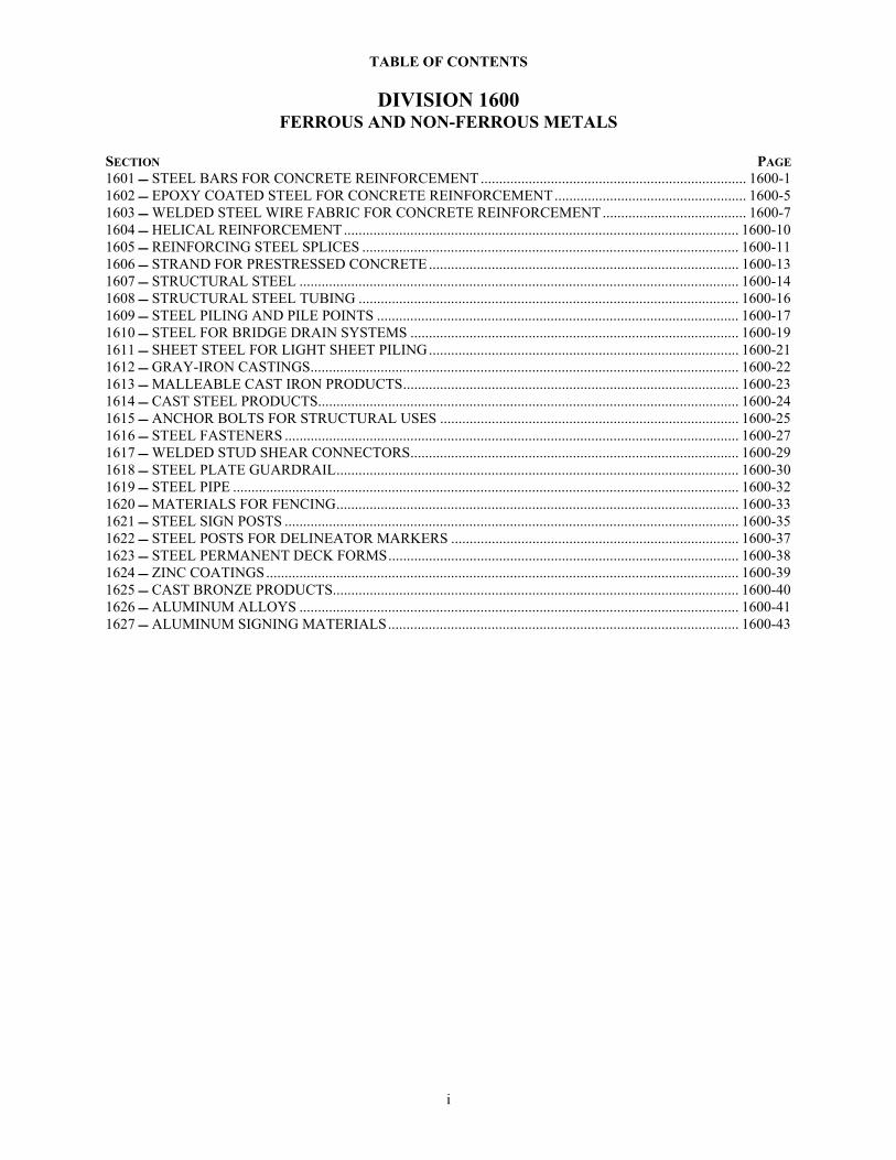
TABLE OF CONTENTS
DIVISION 1600 FERROUS AND NON-FERROUS METALS
SECTION PAGE 1601 STEEL BARS FOR CONCRETE REINFORCEMENT ........................................................................ 1600-1 1602 EPOXY COATED STEEL FOR CONCRETE REINFORCEMENT.................................................... 1600-5 1603 WELDED STEEL WIRE FABRIC FOR CONCRETE REINFORCEMENT ....................................... 1600-7 1604 HELICAL REINFORCEMENT ........................................................................................................... 1600-10 1605 REINFORCING STEEL SPLICES ...................................................................................................... 1600-11 1606 STRAND FOR PRESTRESSED CONCRETE .................................................................................... 1600-13 1607 STRUCTURAL STEEL ....................................................................................................................... 1600-14 1608 STRUCTURAL STEEL TUBING ....................................................................................................... 1600-16 1609 STEEL PILING AND PILE POINTS .................................................................................................. 1600-17 1610 STEEL FOR BRIDGE DRAIN SYSTEMS ......................................................................................... 1600-19 1611 SHEET STEEL FOR LIGHT SHEET PILING.................................................................................... 1600-21 1612 GRAY-IRON CASTINGS.................................................................................................................... 1600-22 1613 MALLEABLE CAST IRON PRODUCTS........................................................................................... 1600-23 1614 CAST STEEL PRODUCTS.................................................................................................................. 1600-24 1615 ANCHOR BOLTS FOR STRUCTURAL USES ................................................................................. 1600-25 1616 STEEL FASTENERS ........................................................................................................................... 1600-27 1617 WELDED STUD SHEAR CONNECTORS......................................................................................... 1600-29 1618 STEEL PLATE GUARDRAIL............................................................................................................. 1600-30 1619 STEEL PIPE ......................................................................................................................................... 1600-32 1620 MATERIALS FOR FENCING............................................................................................................. 1600-33 1621 STEEL SIGN POSTS ........................................................................................................................... 1600-35 1622 STEEL POSTS FOR DELINEATOR MARKERS .............................................................................. 1600-37 1623 STEEL PERMANENT DECK FORMS............................................................................................... 1600-38 1624 ZINC COATINGS................................................................................................................................ 1600-39 1625 CAST BRONZE PRODUCTS.............................................................................................................. 1600-40 1626 ALUMINUM ALLOYS ....................................................................................................................... 1600-41 1627 ALUMINUM SIGNING MATERIALS............................................................................................... 1600-43
i
1601 - STEEL BARS FOR CONCRETE REINFORCEMENT
SECTION 1601
STEEL BARS FOR CONCRETE REINFORCEMENT 1601.1 DESCRIPTION This specification governs the steel bars for concrete reinforcement that are produced from billet steel. 1601.2 REQUIREMENTS a. General. (1) Any plant producing steel bars for concrete reinforcement through this specification must be currently prequalified. A plant is any facility that rolls or otherwise produces the bars from the basis steel. (2) All the bars produced through this specification are to be deformed unless specified otherwise on the in the Contract Documents. (3) When it is required to bend and cut bars in order to produce components for a project, conduct these operations in a fabrication shop before shipment to the project. This requirement applies unless it is specified otherwise in the Contract Documents or documented approval is obtained from the Engineer’s representative. Heating of the bars to facilitate the bending operation is not permitted. b. Material Specifications.
• Carbon steel bars................................................................................................AASHTO M 31 • Rail-steel and Axle-steel bars ...........................................................................AASHTO M 322
1601.3 TEST METHODS Conduct all tests required by the applicable AASHTO material specification of subsection 1601.2b. 1601.4 PREQUALIFICATION a. General. Contact the Bureau Chief, Materials and Research, to arrange for the required sampling, observation of testing procedures and review of the plant quality control program. The plant is to absorb all the Engineer’s representative expenses associated with the inspection. This includes travel, subsistence and lodging, and the expenses of shipping the selected specimen bars to the KDOT Materials and Research Center for comparison testing. It is the option of the Bureau Chief, Materials and Research, to grant approval status to a plant based upon the qualification test and inspection results of the transportation agencies of other states. A plant will be notified by written documentation in the event of any change in their approval status. The Bureau of Materials and Research will maintain a list of all plants that are prequalified and approved to provide bars to KDOT projects. b. Plant Quality Control Requirements. The plant must have a quality control section identified within its organization that is adequately staffed to perform the required lot by lot testing. The plant laboratory must have proper equipment, calibrated according to AASHTO T 67 (ASTM E 4) annually as a minimum, with which to adequately perform all testing according to subsection 1601.3. Provide a copy of the plant quality control plan to the Engineer’s representative during the plant inspection. c. Sampling and Testing Procedure. The Engineer’s representative will select the test samples, at random, at the plant. Provide access to all facilities necessary for the Engineer’s representative to randomly select samples from all lots defined below. Provide plant personnel to cut and label the necessary specimens from the randomly selected bars. (1) Lot size. The lot of reinforcing bars that is subject to sampling includes all sizes, grades, and heats in stock. Remove the samples from 3 different bars from each of 10 heats, i.e., 30 sample bars, unless exceptions are authorized by the Bureau Chief, Materials and Research, or their designated representative. (2) The sample size is 12 feet for all bars selected.
1600-1
1601 - STEEL BARS FOR CONCRETE REINFORCEMENT
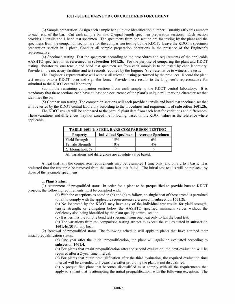
(3) Sample preparation. Assign each sample bar a unique identification number. Durably affix this number to each end of the bar. Cut each sample bar into 2 equal length specimen preparation sections. Each section provides 1 tensile and 1 bend test specimen. The specimens from one section are for testing by the plant and the specimens from the companion section are for the comparison testing by the KDOT. Leave the KDOT’s specimen preparation section in 1 piece. Conduct all sample preparation operations in the presence of the Engineer’s representative. (4) Specimen testing. Test the specimens according to the procedures and requirements of the applicable AASHTO specification as referenced in subsection 1601.2b. For the purpose of comparing the plant and KDOT testing laboratories, one tensile and bend test specimen set from each sample is to be tested by each laboratory. Provide all the necessary facilities and test records required by the Engineer’s representative to witness the tests. The Engineer’s representative will witness all relevant testing performed by the producer. Record the plant test results onto a KDOT form and sign the form. Provide these results to the Engineer’s representative for submittal to the KDOT central laboratory. Submit the remaining companion sections from each sample to the KDOT central laboratory. It is mandatory that these sections each have at least one occurrence of the plant’s unique mill marking character set that identifies the bar. (5) Comparison testing. The companion sections will each provide a tensile and bend test specimen set that will be tested by the KDOT central laboratory according to the procedures and requirements of subsection 1601.2b. The KDOT results will be compared to the parallel plant data from each heat for variations and differences. These variations and differences may not exceed the following, based on the KDOT values as the reference where applicable:
TABLE 1601-1: STEEL BARS COMPARISON TESTING Property Individual Specimen Average Specimen
Yield Strength 15% 6% Tensile Strength 10% 4% Δ Elongation, % 9 6 All variations and differences are absolute value based.
A heat that fails the comparison requirements may be resampled 1 time only, and on a 2 to 1 basis. It is preferred that the resample be removed from the same heat that failed. The initial test results will be replaced by those of the resample specimens. d. Plant Status. (1) Attainment of prequalified status. In order for a plant to be prequalified to provide bars to KDOT projects, the following requirements must be complied with:
(a) With the exceptions as noted in (b) and (c) to follow, no single heat of those tested is permitted to fail to comply with the applicable requirements referenced in subsection 1601.2b. (b) No lot tested by the KDOT may have any of the individual test results for yield strength, tensile strength, or elongation below the AASHTO specified minimum values without the deficiency also being identified by the plant quality control section. (c) It is permissible for one bend test specimen from one heat only to fail the bend test. (d) The variations from the comparison testing are not to exceed the values stated in subsection 1601.4c.(5) for any heat.
(2) Renewal of prequalified status. The following schedule will apply to plants that have attained their initial prequalification status:
(a) One year after the initial prequalification, the plant will again be evaluated according to subsection 1601.4. (b) For plants that retain prequalification after the second evaluation, the next evaluation will be required after a 2-year time interval. (c) For plants that retain prequalification after the third evaluation, the required evaluation time interval will be extended to 3 years thereafter providing the plant is not disqualified. (d) A prequalified plant that becomes disqualified must comply with all the requirements that apply to a plant that is attempting the initial prequalification, with the following exception. The
1600-2

1601 - STEEL BARS FOR CONCRETE REINFORCEMENT
disqualified plant may petition for an immediate reevaluation provided it can be demonstrated to the Bureau Chief, Materials and Research, that the disqualifying deficiencies have been corrected.
(3) Disqualification. All prequalified plants that are currently providing bars for KDOT projects will have their product quality monitored through the use of verification samples.
(a) Verification samples. The Regional Materials Laboratories will randomly select on average 1 verification sample per month from the bars being provided by each prequalified plant for use on KDOT projects. Special arrangements may be considered for plants providing small quantities during the course of a year. These samples are to include all bar grades and sizes that may be available for use on KDOT projects. These samples will be obtained from various shipments and at any fabrication, coating, or precast facility, or warehouse selected by the Regional Materials Engineer. On occasion, it will be necessary for the Regional Materials Engineer to notify the District to obtain verification samples at a project. Samples will be submitted to the MRC for testing according to the procedures and requirements of subsection 1601.2b. Reduction in sampling will follow the criteria established in Part V, Appendix A, Multi-level Sampling Frequency Chart, with the following exception: Reduced Frequency Approved by Regional Materials Engineer with Notification to Bureau of Materials and Research. (b) Verification sample testing. The verification samples are to comply with the minimum requirements of the applicable AASHTO specification of subsection 1601.2b with the exceptions as noted in the following. • It will be permissible for the test results from only one annual verification sample from each
prequalified plant to be less than the following:
TABLE 1601-2: STEEL BARS VERIFICATION TESTING Property Requirement
Unit Weight: 99% of the specified minimum Yield Strength: 95% of the specified minimum Tensile Strength: 95% of the specified minimum Elongation, %: Specified minimum minus 2
• Not more than 10% of the annual verification samples from each prequalified plant will be
permitted to have test results less than the applicable specification minimums. • Not more than one annual verification sample from each prequalified plant will be permitted
to fail the bend test. • In the event that the verification samples fail to comply with the proceeding, the Engineer’s
representative may resample the failing heat(s) one time only on a 2 to 1 basis or reject the failing heat(s). The Contractor is to replace the rejected heats at no additional cost to the KDOT. The initial test results will be replaced by those of the resample specimens.
Failure of the verification sample bars from a plant to comply with subsection 1601.4d.(3)(b) will result in disqualification of the plant and removal from the prequalified source list. In the event of disqualification, the plant is subject to subsection 1601.4. A plant that fails to comply with subsection 1601.4d.(3)(b) 2 times, consecutive or otherwise, will be permanently disqualified. 1601.5 BASIS OF ACCEPTANCE a. The plant must be currently prequalified. b. Submit for approval to the project Engineer and MRC, a copy of a Type A certification (certified mill test report), as specified in DIVISION 2600, that governs the analysis of all bar steel heats delivered to the project. c. The Engineer’s representative of the project must be provided with shipping orders, an invoice, or cover letter that documents the project number, bar sizes and grades, heat, job, or mill order number(s), and the total weight of each heat of the represented bars delivered to the project.
1600-3
1601 - STEEL BARS FOR CONCRETE REINFORCEMENT
d. The Engineer’s representative of the project must be provided with a document stating that the bars delivered to the project comply to this specification. This documentation must bear the signature and title of an official of the plant with Contract Document binding authority, and must be notarized. This requirement may be included on the certified mill test report referenced in subsection 1601.5b. e. Single or bound groups of bars must be tagged or otherwise marked in a durable manner. At a minimum, this identification must list the bar manufacturers corporate identification and plant location, the heat, job, or mill order number, and display a copy of the plant’s unique mill marking character set that identifies the bar. f. The final disposition of the bars will be completed at the final destination as the result of inspection for the quality of workmanship and the delivery condition.
1600-4
1602 - EPOXY COATED STEEL FOR CONCRETE REINFORCEMENT
SECTION 1602
EPOXY COATED STEEL FOR CONCRETE REINFORCEMENT 1602.1 DESCRIPTION This specification covers the requirements for epoxy coated steel for concrete reinforcement. The protective epoxy coating is applied to the reinforcing steel by the electrostatic spray or the electrostatic fluidized-bed method. 1602.2 REQUIREMENTS a. General. (1) Appendices to the standards cited below that are identified as nonmandatory information in those standards, are to be considered mandatory information for the purposes of this specification. (2) Applicators must be certified under the Concrete Reinforcing Steel Institute (CRSI) Epoxy Coating Plant Certification program. b. Epoxy Coated Steel Bars. (1) Unless shown otherwise in the Contract Documents, use uncoated steel bars that comply with SECTION 1601 for straight bars or SECTION 1604 for helical reinforcement. (2) Apply an epoxy coating that complies with ASTM A 775. (3) Fabricators must comply with the provisions of ASTM D 3963, “Standard Specification for Fabrication and Jobsite Handling of Epoxy-Coated Reinforcing Steel Bars." c. Epoxy Coated Steel Wire and Welded Wire Fabric. (1) Unless shown otherwise on the Contract Documents, use material which complies with SECTION 1603 for welded wire fabric or SECTION 1604 for steel wire. (2) Apply an epoxy coating that complies with ASTM A 884, Type 1 with Class A coating thickness. d. Dowel Bars and Straight Tie Bars for Pavement. (1) Unless shown otherwise in the Contract Documents, use uncoated steel bars that comply with SECTION 1601. (2) Apply an epoxy coating that complies with ASTM A 775 or ASTM A 934. Bent tie bars should be coated and handled as regular epoxy coated steel bars under subsection 1602.2 b. (3) Coating or patching material need not be applied to the cut end faces of the bars. For dowel bars to be mounted in baskets, coating will not be required within 2 inches of the end that will be fixed in the supporting basket by welding. (4) Cut the bars by a method that minimizes heat input and surface damage and results in no appreciable deformation of the ends. 1602.3 TEST METHODS As specified in the ASTM standards referenced above. 1602.4 PREQUALIFICATION a. Applicators. Epoxy coating applicator plants supplying material to KDOT projects must be prequalified. Send a copy of the most recent CRSI certification grade sheets and inspection notes to the Bureau of Materials and Research for review. Satisfactory certification will serve to prequalify the plant until the next anniversary date. In order to maintain prequalified status, send copies of the CRSI certification grade sheets and inspection notes each year as soon as they are received from CRSI. b. Organic Coatings. Organic coatings used for protection of reinforcing steel under this specification must be prequalified under ASTM A 775 or in the case of dowel bars or straight tie bars for pavement, ASTM A
1600-5
1602 - EPOXY COATED STEEL FOR CONCRETE REINFORCEMENT
934 if applicable. Manufacturers desiring to supply material should submit a certified test report by an independent laboratory regularly inspected by the Cement and Concrete Reference Laboratory (CCRL) to the Bureau of Materials and Research. c. Patching Material for Organic Coatings. Patching material for organic coatings used for protection of reinforcing steel under this specification must be prequalified under ASTM D 3963. Manufacturers desiring to supply material should submit a certified test report by an independent laboratory regularly inspected by the Cement and Concrete Reference Laboratory (CCRL) to the Bureau of Materials and Research. d. Prequalified Lists. The Bureau of Materials and Research will maintain lists of prequalified applicators, organic materials and patching materials for use on KDOT projects. 1602.5 BASIS OF ACCEPTANCE Receipt and approval by the Regional Materials Laboratory of the documents required for the uncoated reinforcing steel. Receipt and approval by the Regional Materials Laboratory of a certification prepared by the Plant that applied the coating, stating that all bars have been coated in accordance with this specification. Provide this certification to the KDOT representative at the coating plant. Satisfactory results of bend tests (if applicable), coating thickness and continuity tests conducted on the coated material by representatives of KDOT. Visual inspection at destination for proper tagging of each bundle to enable identification of each heat or lot, for condition and for other properties.
1600-6
1603 - WELDED STEEL WIRE FABRIC FOR CONCRETE REINFORCEMENT
SECTION 1603
WELDED STEEL WIRE FABRIC FOR CONCRETE REINFORCEMENT
1603.1 DESCRIPTION This specification governs the welded steel wire fabric for concrete reinforcement that is produced from deformed or non-deformed steel wire or a combination thereof. 1603.2 REQUIREMENTS a. General. (1) Any plant producing welded steel wire fabric for concrete reinforcement through this specification must be currently prequalified. A plant is any facility that welds the steel wire fabric from wire produced internally or obtained from an external source. (2) The fabric provided through this specification can be produced from deformed or non-deformed wire or a combination of both unless specified otherwise in the Contract Documents. (3) The fabric is to be produced to the dimensions and sizes as specified the Contract Documents. Deviations from this requirement must have the documented approval of the Engineer’s representative. b. Material Specifications.
• Non-deformed steel wire ................................................................................AASHTO M 32 • Deformed steel wire .......................................................................................AASHTO M 225 • Fabric produced from non-deformed steel wire .............................................AASHTO M 55 • Fabric produced from deformed wire or a combination of deformed
and non-deformed wire ..................................................................................AASHTO M 221 1603.3 TEST METHODS Conduct all tests as specified in subsection1603.2b. 1603.4 PREQUALIFICATION a. General. Contact the Bureau Chief, Materials and Research, to arrange for the required sampling, observation of testing procedures and review of the plant quality control program. The plant is to absorb all the Engineer’s representative’s expenses associated with the inspection. This includes travel, subsistence and lodging, and the expenses of shipping the selected wire and fabric specimens to the KDOT Materials and Research Center for comparison testing. It is the option of the Bureau Chief, Materials and Research, to grant prequalified status to a plant based upon the qualification test and inspection results of the transportation agencies of other states. A plant will be notified by written documentation in the event of any change in their prequalified status. The Bureau of Materials and Research will maintain a list of all plants that are prequalified to provide fabric to KDOT projects. b. Plant Quality Control Requirements. The plant must have a quality control section identified within its organization that is adequately staffed to perform the required lot by lot testing. The plant laboratory must have proper equipment, calibrated according to AASHTO T 67 (ASTM E 4) annually as a minimum, with which to adequately perform all testing required through subsection1603.3. Provide a copy of the plant quality control plan the Engineer’s representative during the plant inspection. c. Sampling and Testing Procedure. The Engineer’s representative will select the test samples, at random, at the plant. Provide access to all facilities necessary for the Engineer’s representative to randomly select samples from all lots defined below. Provide plant personnel to cut and label the necessary specimens from the randomly selected wire and fabric. (1) Lot size. The reinforcing fabric and wire that is subject to sampling includes all sizes and production
1600-7
1603 - WELDED STEEL WIRE FABRIC FOR CONCRETE REINFORCEMENT
lots of fabric, and heats or lots of wire in stock. Remove the fabric samples from 10 different production lots. Remove 3 wire samples from each of 10 different lots, heats when available, of wire being utilized to produce fabric at the plant. Vary the size of the fabric and wire that is sampled to the greatest extent that availability permits. This is for the purpose of obtaining a representative cross-section of the plant production. These sampling requirements apply unless exceptions are authorized by the Bureau Chief, Materials and Research, or their designated representative. (2) Fabric samples are to be contiguous sections, i.e., all wires and welds intact, that are 6 longitudinal or ‘running’ wires in width by 10 transverse wires in length. Wire tensile samples are to be 2 m in length. (3) Sample preparation. Assign each fabric and wire sample a unique identification number. Durably affix this number to each end of the wire tensile and fabric samples. For definition purposes, the length direction of a fabric sample is parallel to the longitudinal wires. Cut each fabric and wire sample into 2 equal length specimen preparation sections. This cut is perpendicular to the longitudinal wires for the fabric samples. Each wire section provides a tensile and bend test specimen and each fabric section provides 4 weld shear test specimens. The specimens from one section are for testing by the plant and the specimens from the companion section are for the comparison testing by the KDOT. Leave the KDOT’s specimen preparation sections in one piece. Conduct all sample preparation operations in the presence of the Engineer’s representative. (4) Specimen testing. Test the specimens according to the procedures and requirements of the applicable AASHTO specification as referenced in subsection 1603.2b. For the purpose of comparing the plant and KDOT testing laboratories, one tensile and bend test set from each sample and one weld shear test specimen set from each sample is to be tested by each laboratory. Provide all the necessary facilities and test records required by the Engineer’s representative to witness the tests. The Engineer’s representative will witness all relevant testing performed by the producer. Record the plant test results onto a KDOT form and sign the form. Provide these results to the Engineer’s representative for submittal to the KDOT central laboratory. Submit the remaining companion sections from each sample to the KDOT central laboratory. It is mandatory that these sections retain their unique identification number during shipment and when delivered to the central laboratory. (5) Comparison testing. The companion sections will each provide a tensile and bend test specimen set and a set of 4 weld shear test specimens that will be tested by the KDOT central laboratory according to the procedures and subsection 1603.2b. The KDOT results will be compared to the parallel plant data from each heat or lot for variations and differences. These variations and differences may not exceed the following, based on the KDOT values as the reference where applicable:
TABLE 1603-1: WELDED STEEL WIRE FABRIC COMPARISON TESTING
Property Individual Specimen Test Results
Average Test Results for the Heat or Lot
Tensile Strength 10% 5% All variations and differences are absolute value based.
A heat or lot that fails the comparison requirements may be resampled one time only, and on a 2 to 1 basis. It is preferable that the resample be removed from the same heat or lot that failed. The initial test results will be replaced by those of the resample specimens. A lot that fails the weld shear test requirements may be resampled in accordance with the procedures of subsection 1603.2b. d. Plant Status. (1) Attainment of prequalified status. In order for a plant to be prequalified to provide welded wire fabric to KDOT projects, the following requirements must be complied with:
(a) With the exceptions as noted in (b) and (c) to follow, no single heat of those tested is permitted to fail to comply with the applicable requirements referenced in subsection 1603.2b. (b) No heat or lot tested by the KDOT may have any of the individual test results for yield strength, tensile strength, reduction of area (when applicable), or the average weld shear strength below the AASHTO specified minimum values without the deficiency also being identified by the plant quality control section.
1600-8
1603 - WELDED STEEL WIRE FABRIC FOR CONCRETE REINFORCEMENT
(c) It is permissible for one bend test specimen from 1 heat or lot only to fail the bend test. (d) The variations from the comparison testing are not to exceed the values stated in subsection 1603.4c(5) for any heat or lot of wire.
(2) Renewal of prequalified status. Plants that have attained their initial prequalification status will remain prequalified unless the results of verification samples indicate quality control deviations, or there are significant changes in production methods or material characteristics. Any variations in production methods or material characteristics must be immediately brought to the attention of the Bureau Chief, Materials and Research, to determine if a subsequent prequalification evaluation is required. A prequalified plant that becomes disqualified must comply with all the requirements that apply to a plant that is attempting the initial prequalification, with the following exception. The disqualified plant may petition for an immediate reevaluation provided it can be demonstrated to the Bureau Chief, Materials and Research, that the disqualifying deficiencies have been corrected. (3) Disqualification. All prequalified plants that are currently providing welded steel wire fabric for KDOT projects will have their product quality monitored through the use of verification samples.
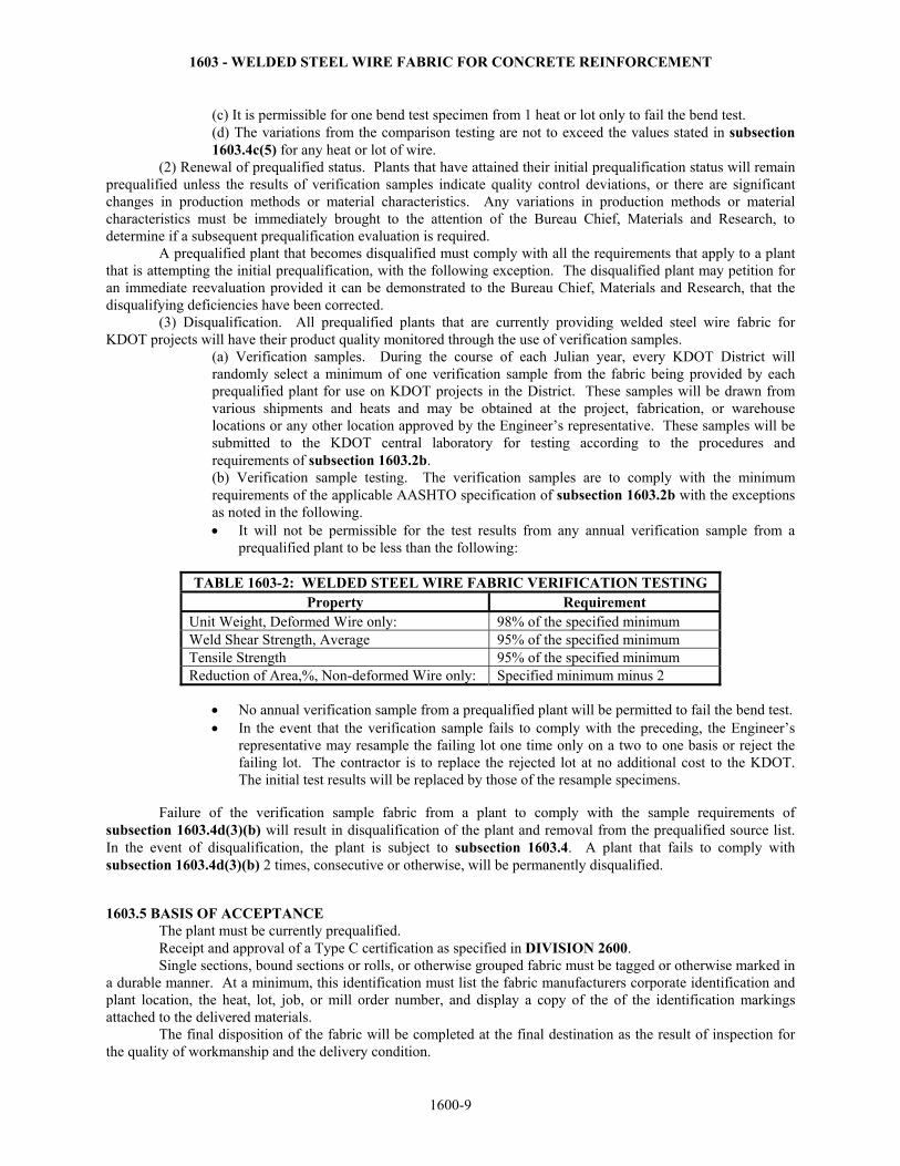
(a) Verification samples. During the course of each Julian year, every KDOT District will randomly select a minimum of one verification sample from the fabric being provided by each prequalified plant for use on KDOT projects in the District. These samples will be drawn from various shipments and heats and may be obtained at the project, fabrication, or warehouse locations or any other location approved by the Engineer’s representative. These samples will be submitted to the KDOT central laboratory for testing according to the procedures and requirements of subsection 1603.2b. (b) Verification sample testing. The verification samples are to comply with the minimum requirements of the applicable AASHTO specification of subsection 1603.2b with the exceptions as noted in the following. • It will not be permissible for the test results from any annual verification sample from a
prequalified plant to be less than the following:
TABLE 1603-2: WELDED STEEL WIRE FABRIC VERIFICATION TESTING Property Requirement
Unit Weight, Deformed Wire only: 98% of the specified minimum Weld Shear Strength, Average 95% of the specified minimum Tensile Strength 95% of the specified minimum Reduction of Area,%, Non-deformed Wire only: Specified minimum minus 2
• No annual verification sample from a prequalified plant will be permitted to fail the bend test. • In the event that the verification sample fails to comply with the preceding, the Engineer’s
representative may resample the failing lot one time only on a two to one basis or reject the failing lot. The contractor is to replace the rejected lot at no additional cost to the KDOT. The initial test results will be replaced by those of the resample specimens.
Failure of the verification sample fabric from a plant to comply with the sample requirements of subsection 1603.4d(3)(b) will result in disqualification of the plant and removal from the prequalified source list. In the event of disqualification, the plant is subject to subsection 1603.4. A plant that fails to comply with subsection 1603.4d(3)(b) 2 times, consecutive or otherwise, will be permanently disqualified. 1603.5 BASIS OF ACCEPTANCE The plant must be currently prequalified. Receipt and approval of a Type C certification as specified in DIVISION 2600. Single sections, bound sections or rolls, or otherwise grouped fabric must be tagged or otherwise marked in a durable manner. At a minimum, this identification must list the fabric manufacturers corporate identification and plant location, the heat, lot, job, or mill order number, and display a copy of the of the identification markings attached to the delivered materials. The final disposition of the fabric will be completed at the final destination as the result of inspection for the quality of workmanship and the delivery condition.
1600-9
1604 - HELICAL REINFORCEMENT
SECTION 1604
HELICAL REINFORCEMENT 1604.1 DESCRIPTION This specification covers steel wire and steel bars intended for use in helical reinforced members. 1604.2 REQUIREMENTS Provide materials that comply with AASHTO M 32 for plain, uncoated wire, or AASHTO M 31 for carbon steel bars. 1604.3 TEST METHODS Test methods as cited in the AASHTO references. 1604.4 PREQUALIFICATION Manufacturers desiring to provide material under this specification must be prequalified under the provisions of:
• Steel bars ........................................................................................................SECTION 1601 • Uncoated wire ................................................................................................SECTION 1603 • Epoxy coated reinforcement ..........................................................................SECTION 1602
1604.5 BASIS OF ACCEPTANCE Prequalification as required by subsection 1604.4. Submit for approval, to the project Engineer representative and MRC, a Type A certification (certified mill test report), as specified in DIVISION 2600, that governs the analysis of all bar or wire steel heats delivered to the project. Receipt and approval by the Field Engineer of a copy of the shipping orders or invoice showing the project number, heat or lot number, steel size and quantity in the shipment. Tag each bundle of helical reinforcement sent to the project with a plastic or metal tag which lists the plant name and the heat or lot number, or other identification tying the material to the certifications and invoices in subsections 1604.5a. and 1604.5b.
1600-10
1605 - REINFORCING STEEL SPLICES
SECTION 1605
REINFORCING STEEL SPLICES 1605.1 DESCRIPTION This specification covers devices and systems for splicing steel bars for concrete reinforcement. Thermomechanical splices are produced by a process that introduces molten filler metal into an annular space around the bars created by a high strength steel sleeve of larger diameter than the bars. Make the mechanical splices with any mechanical device or system which will meet the physical requirements cited below. 1605.2 REQUIREMENTS When tested in tension, develop all splices at least 125% of the minimum yield strength specified for the bars being spliced. For those splicing systems to be prequalified in the “fatigue resistant” group, provide splices capable of withstanding a load range of 12 ksi (3 ksi to 15 ksi, tension) for a minimum of 1,000,000 cycles. Prepare and mount splices on bars in a fabricator's shop for shipment to the project that meet all requirements of SECTION 1601 including prequalified plant status. 1605.3 TEST METHODS Splicing devices or systems will be tension tested according to the procedures of AASHTO M 31, “Deformed and Plain Carbon Steel Bars for Concrete Reinforcement." 1605.4 PREQUALIFICATION Prepare 3 fully assembled test specimens each for bar sizes number 4, 6 and 8, and forward them to the Engineer of Tests along with the following information:
• Name, address and telephone number of the manufacturer. Include the name of the preferred contact person.
• Brand name of the splice. • Type and description of the splice. • Information regarding recommended usage and splicing instructions. • Material Safety Data Sheets (if applicable). • For those splicing systems to be prequalified in the “fatigue resistant” group, submit test results from
an independent testing laboratory demonstrating that the splice meets the fatigue requirements described above. Test splices for #4, #8, and #11 size, Grade 60 reinforcing steel. These sizes represent the small, medium, and large sizes common in construction.
Exceptions to the bar sizes specified above may be authorized by the Engineer of Tests. The samples provided will be tested to destruction and test reports prepared. During testing, the Engineer of Tests will determine if operator prequalification is required for field and/or fabricator shop splicing, and enter that information on the test reports. The test reports and the information supplied will be reviewed by the Bureau Chief of Materials and Research. The manufacturer will be advised as to whether or not the product is prequalified. The Bureau of Materials and Research will maintain a list of prequalified splicing systems. Products will remain prequalified as long as the manufacturing processes remain unchanged, and field experience indicates that the product functions appropriately. Changes in manufacturing processes require new prequalification testing. Failure of the product to function appropriately in the field will be cause for removal from prequalified status. Products removed from prequalified status will be considered for requalification if the manufacturer can provide evidence that the cause of failure has been positively identified, and necessary changes and quality control measures have been implemented to eliminate that cause. Complete prequalification testing will be required for products that have been removed from prequalified status.
1600-11
1605 - REINFORCING STEEL SPLICES
1605.5 BASIS OF ACCEPTANCE Prequalification as specified in subsection 1605.4. Receipt and approval of a Type C certification as specified in DIVISION 2600. Satisfactory results of testing by lot during construction, as outlined in DIVISION 700.
1600-12
1606 - STRAND FOR PRESTRESSED CONCRETE
SECTION 1606
STRAND FOR PRESTRESSED CONCRETE 1606.1 DESCRIPTION This specification covers 7-wire, non-coated steel strand for use in pre-tensioned, pre-stressed concrete construction. 1606.2 REQUIREMENTS Provide wire strand for use in bonded and pre-tensioned concrete that complies with ASTM A 416. Provide low relaxation, Grade 270 strand unless otherwise specified. Store strand provided under this specification under conditions which maintains the strand in a dry condition and not in direct contact with the soil. When properly stored, the strand may remain in storage for a period not to exceed 6 months from the date of delivery to the pre-stress concrete production plant. Strand in storage in excess of 6 months must be re-tested by the manufacturer or an independent laboratory and a new certification issued before using it. 1606.3 TEST METHODS Test material as specified in ASTM A 416. 1606.4 PREQUALIFICATION None Required. 1606.5 BASIS OF ACCEPTANCE Acceptance of strand provided under this specification will be based on satisfactory results of tests conducted at the MRC on samples representing each lot of material. Consult Part V for a reduced testing frequency for producers with established compliance records.
1600-13
1607 - STRUCTURAL STEEL
SECTION 1607
STRUCTURAL STEEL 1607.1 DESCRIPTION This specification governs the structural steel shapes, plates, bars, and bearing pins utilized for construction purposes. 1607.2 REQUIREMENTS a. General. Dimensions, standard ASTM/AISC shapes, and specific fabrication requirements are as specified in the Contract Documents. Property requirements for the base steel are governed by the classification, designation, or grade of steel specified in the Contract Documents and in accordance with subsection 1607.2b. If a steel component is utilized in a fracture critical application, this must be designated in the Contract Documents according to the provisions of AASHTO M 270 inclusive of Supplementary Requirement S84. b. Structural Steel. (1) Provide steel that complies with AASHTO M 270 or ASTM A 709. Miscellaneous structural items may utilize ASTM A 36 or A 500; etc., but material changes to the Contract Documents require the approval of the State Bridge Office or the Bureau of Materials and Research, Operations Engineer. When AASHTO M 270 is specified, and unless shown otherwise in the Contract Documents, the requirements for toughness testing, Zone 2 or Zone 3 level as specified in the Contract Documents, are mandatory whether the steel component is subject to tensile stress or utilized in a fracture critical application or not. When ASTM A 709 followed by the letter “T” or “F” and a temperature zone number is specified, the supplementary requirements for toughness described above for AASHTO M 270 are required. (2) Steel component edges that are produced by methods, such as mechanical shearing, that induce significant residual stress fields are to be stress relieved by machining not less than ¼ inch of material from the edge if the component is over 5/8 inch in thickness and subject to a calculated stress field. Fabrication procedures that produce low radius edge intersections are to have these stress concentration effects reduced by a fillet at the intersection of not less than 1 inch radius in accordance with the requirements and procedures of AASHTO/AWS D1.5. Discontinuities such as seams, rolling laps, tears, gas porosity etc. observed in steel components and weldments are subject to the detection methods, acceptability criteria, repair methods and procedures, and other requirements of AASHTO/AWS D1.5. Unless specified otherwise, steel components and fabrications are subject to AASHTO/AWS D1.5 for the quality of the final product. In addition, all structural steel components are subject to the quality requirements of ASTM A 6 throughout the fabrication process. (3) Produce bearing pins from steel that complies with ASTM A 108, SAE 1018, or subsection 1607.2b.(1) unless specified otherwise in the Contract Documents. c. Structural Steel (Merchant Quality). This is a hot-rolled carbon steel in shapes or bars for use in non-critical parts of a structure or facility. It must be suitable for moderate cold bending, moderate hot forming, punching and welding, and capable of serving it’s intended purpose. 1607.3 TEST METHODS Conduct all tests required by the applicable AASHTO, ASTM, AISC, AWS, or other component or material specifications of subsection 1607.2b. 1607.4 PREQUALIFICATION Not applicable. 1607.5 BASIS OF ACCEPTANCE a. Structural Steel. Submit for approval to the project Engineer and MRC a Type A certification
1600-14
1607 - STRUCTURAL STEEL
(certified mill test report), as specified in DIVISION 2600, that governs the analysis of all bar steel heats delivered to the project. b. Structural Steel (Merchant Quality). Acceptance will be based on visual inspection for condition and compliance with dimensional requirements. c. The final disposition of steel components provided through this specification will be completed at the final destination as the result of inspection by field personnel for the quality of workmanship, the delivery condition, compliance with dimensional requirements and receipt. Certain fabricated structural components may also require inspection during the production process at the fabrication facility.
1600-15
1608 - STRUCTURAL STEEL TUBING
SECTION 1608
STRUCTURAL STEEL TUBING 1608.1 DESCRIPTION This specification governs cold and hot formed welded and seamless steel structural tubing. This includes round, square, rectangular, or special shape structural tubing, tapered or nontapered, for welded, riveted, or bolted construction of bridges, buildings, and general applications. 1608.2 REQUIREMENTS a. General. (1) Unless specified otherwise in the Contract Documents, welds in tubing and structures fabricated from tubing are to comply with AWS D1.1. Circumferential welds and longitudinal welds within the area of a slip joint are to exhibit complete joint penetration. Other longitudinal welds are permitted partial joint penetration as a percentage of the governing plate thickness. This value is not permitted to be less than 60% for a plate thickness of 0.4 inch or less and not less than 80% for a plate thickness greater than 0.4 inch. Discontinuities such as hot and cold cracks, craters, undercut, gas porosity, inclusions, etc. observed in welds are subject to the detection methods, acceptability criteria, repair methods and procedures, and AWS D1.1. Nonstandard or special shape tubing is to comply with the design specified in the Contract Documents. (2) If not governed by the component specification, when corrosion protection coatings are specified for tubing and tubing structures, these components are to be zinc coated by hot dip galvanizing after fabrication in compliance with ASTM A 123, Thickness Grade 85. Aluminum coating application after fabrication is acceptable when permitted and regulated by the specification that governs the component. Grade 85 should still be a valid designation. b. Materials Specifications.
• Cold formed welded and seamless structural steel tubing .............................ASTM A 500 • Hot formed welded and seamless structural steel tubing ...............................ASTM A 501
1608.3 TEST METHODS Conduct all tests required by the applicable ASTM, AWS, or other component or material specifications of subsection 1608.2. Coating thickness may be measured by any one of the methods specified in ASTM B 633 and by eddy current methods, ASTM B 244, provided that appropriate calibration procedures and standards have been applied. The magnetic induction and eddy current methods are nondestructive in nature and are preferred. Destructive techniques, i.e., coating removal, may be utilized as referee methods. 1608.4 PREQUALIFICATION Not applicable. 1608.5 BASIS OF ACCEPTANCE Submit for approval to the project Engineer and Materials Regional Laboratory a Type A certification (certified mill test report), as specified in DIVISION 2600, that governs the analysis of all heats delivered to the project. Inspection, and testing when applicable, by field personnel of steel structural tubing and structures fabricated from this tubing for compliance with corrosion protection coating thickness, weld quality, and dimensional requirements. The final disposition of tubing and structures fabricated from tubing will be completed at the final destination as the result of inspection for the quality of workmanship, the delivery condition. Certain fabricated tubing and tubing structures may also require inspection during the production process at the fabrication facility.
1600-16
1609 - STEEL PILING AND PILE POINTS
SECTION 1609
STEEL PILING AND PILE POINTS 1609.1 DESCRIPTION This specification governs structural steel piles, steel shells to be utilized as forms for in situ cast concrete piles, steel sheet piling, and fabricated or cast steel pile points. 1609.2 REQUIREMENTS a. General. Dimensions, standard ASTM/AISC shapes, pipe and tubing sizes, weights, wall thickness, and specific fabrication requirements are as specified in the Contract Documents. Comply with nationally accepted size standards whenever possible. Property requirements for the base steel are governed by the classification, designation, or grade of steel specified in the Contract Documents and with subsection 1609.2b. b. Materials Specifications. (1) Unless specified otherwise, provide steel piles that comply with the ASTM/AISC standard shape dimensions and ASTM A 6. The majority of the AISC shapes are also governed by the ASTM specification, in that instance, the ASTM requirements prevail. Unless specified otherwise, provide steel that complies with ASTM A 709 Grade 50 or ASTM A 572 Grade 50. As a minimum, each pile section must have the heat number durably affixed to it. (2) Steel shells with respect to their longitudinal dimension may be of a uniform or tapered section, fluted, helix corrugated, or a non-deformed surface round pipe. Pipe may be seamless, electric resistance welded longitudinally, or welded in a helix pattern by gas metal arc welding (GMAW) or other acceptable method. Furnace welding is not permitted. Provide pipe or pipe piles for shells that complies with ASTM A 53 Grade B with the hydrostatic and flattening test and chemical requirements waived, or A 252 Grade 2, respectively. In addition, the testing requirements of DIVISION 1600 for A 53 pipe are not required. Unless specified otherwise, provide steel for fluted and corrugated shells that complies with ASTM A 568 cold rolled carbon steel sheet SAE 1010, maximum carbon level. The dimensional and weight tolerances of A 53 or A 252 apply to all steel shells with the diameter of fluted and helix corrugated shells defined by the flute or helix crown diameter. Specify wall thickness in thousandths of an inch. The degree of taper for tapered shells is as defined in the Contract Documents with the outside diameter at any location as previously defined. Any completed shell, with point, is to be of sufficient rigidity so as to as to retain the original shape profile, resist the soil pressure, and not permit the influx of water after it and the adjacent shells have been driven into place. As a minimum, each pile section must have the heat number durably affixed to it. (3) Provide steel sheet piling that complies with AASHTO M 202. As a minimum, each section must have the heat number durably affixed to it. (4) Pile points may be fabricated or cast from steel as specified in the Contract Documents. For steel piles, provide only cast steel points that comply with ASTM A 148, Grade 80-50. For steel shells, fabricate points out of steel that complies with ASTM A 36 or provide cast steel points that comply with ASTM A 27, Grade 65-35. Other steels and fabrication procedures may be used if granted prior approval by the KDOT. Submit shop drawings that provide detailed dimensions, steel designation, point attachment methods, and any other pertinent information to the KDOT for approval. As a minimum, each point must have the heat or lot number durably affixed to it. 1609.3 TEST METHODS Conduct all tests required by the applicable AASHTO, ASTM, AISC, or other component or material specifications of subsection 1609.2b. 1609.4 PREQUALIFICATION Not applicable.
1600-17

1609 - STEEL PILING AND PILE POINTS
1609.5 BASIS OF ACCEPTANCE Submit for approval to the project Engineer and MRC a Type A certification (certified mill test report), as specified in DIVISION 2600, that governs the analysis of all heats delivered to the project. Components are to be identified according to subsection1609.2b. The final disposition of structural steel pile sections and points provided through this specification will be completed at the final destination as the result of inspection by field personnel for the quality of workmanship, the delivery condition, the condition after being driven, compliance with dimensional requirements, receipt and approval of the associated required documentation, and proper identification of the components.
1600-18
1610 - STEEL FOR BRIDGE DRAIN SYSTEMS
SECTION 1610
STEEL FOR BRIDGE DRAIN SYSTEMS 1610.1 DESCRIPTION This specification governs steel drainage systems applied to bridges. 1610.2 REQUIREMENTS a. General. The drainage system design, dimensions, method of corrosion protection, and specific fabrication requirements are to be as specified in the Contract Documents. Each method of corrosion protection dictates the use of certain steels. Only 1 method of corrosion protection is allowed for a structure. Property requirements for the steels and components are governed by the classifications, designations, or grades of steel, and the component specifications designated in the Contract Documents and in accordance with subsection 1610.2b. b. Material Specifications. (1) When it is specified that corrosion protection be provided by zinc coatings applied by hot dip galvanizing, identified as HDG, use structural steel and pipe that complies with ASTM A 36 and A 53 respectively. The testing requirements of DIVISION 1600 for A 53 pipe are not required. Coat the pipe with zinc in accordance with A 53. Furnace welded pipe is not acceptable and the hydrostatic and flattening tests are not required. Coat components produced from structural steel and or pipe with zinc by hot dip galvanizing, preferably after fabrication, in compliance with ASTM A 123. When coating by this method after fabrication is not practical, protect all areas where the coating is removed by welding or other procedures by application of a zinc or zinc alloy coating as specified in DIVISION 1800. Thoroughly clean the damaged areas before application of the coating. (2) When it is specified that corrosion protection be provided by copper bearing weathering steels, identified as CBW, use structural steel and pipe that complies with ASTM A 242 or A 588 and ASTM A 618, Grade II, respectively. The minimum acceptable copper content is 0.20%. (3) When it is specified that corrosion protection be provided through the use of stainless steels, identified as SST, use basis stainless structural steel and pipe that complies with ASTM A 240, AISI/SAE designations 302, 304 or 305, or ASTM A 358, Class 2, Grade 304 and A 312 respectively. Hydrostatic testing is not required. Weld stainless steels according to the procedures of the applicable specification in order to avoid cracking and weld area sensitization to corrosion. 1610.3 TEST METHODS Conduct all tests required by the applicable ASTM or other component or material specifications of subsection 1610.2b. Measure the coating thickness by any one of the methods specified in ASTM B 633 and by eddy current methods, ASTM B 244, provided that appropriate calibration procedures and standards have been applied. The magnetic induction and eddy current methods are nondestructive in nature and are preferred. Destructive techniques, i.e., coating removal, may be utilized as referee methods. 1610.4 PREQUALIFICATION Not applicable. 1610.5 BASIS OF ACCEPTANCE Submit for approval to the Regional Materials Laboratory a Type A certification (certified mill test report), as specified in DIVISION 2600, for all drainage system components, excluding pipe, when the HDG or CBW corrosion protection method is specified and all components, including pipe, when the SST method is specified. Receipt and approval of a Type D certification as specified in DIVISION 2600 for pipe when the HDG or CBW corrosion protection method is specified. Inspection and testing by field personnel of all components for compliance with dimensional requirements for all drainage system components and corrosion protection coating thickness when the HDG protection method is
1600-19

1610 - STEEL FOR BRIDGE DRAIN SYSTEMS
specified. Coating thickness is to be measured according to any of the procedures of subsection 1610.3. The final disposition of all drainage system components will be completed at the final destination as the result of inspection for the quality of workmanship and the delivery condition.
1600-20
1611 - SHEET STEEL FOR LIGHT SHEET PILING
SECTION 1611
SHEET STEEL FOR LIGHT SHEET PILING 1611.1 DESCRIPTION This specification governs the sheet steel utilized to fabricate lightweight or thin sheet piling. 1611.2 REQUIREMENTS a. General. Provide steel sheets intended for these applications that comply with the design, dimensions, requirement for corrosion protection, and specific fabrication requirements as specified in the Contract Documents. The sheets may be flanged, interlock seamed, corrugated, or flat. When properly driven, the sheets interlock or overlap so as to form a relatively impervious and continuous barrier. Provide the sheets with zinc coatings applied by hot dip galvanizing when corrosion protection is specified. The classifications, designations, grades of steel govern property requirements for the steels and corrosion protection, and or the specifications designated in the Contract Documents and in accordance with subsection 1611.2b. b. Material Specifications. (1) When corrosion protection is not required, provide basis sheet steel that complies with ASTM A 1011, Grade 30. (2) When corrosion protection is specified, provide basis sheet steel that complies with ASTM A 653, Grade 33, and is zinc coated by the hot dip galvanizing process in compliance with ASTM A 653, Coating Designation G90. 1611.3 TEST METHODS Conduct all tests required by the applicable ASTM specifications of subsection 1611.2b. Coating thickness may be measured by any one of the methods referenced in ASTM B 633 and by eddy current methods, ASTM E 376 (B 244 may also be useful as a technique guideline) provided that appropriate calibration procedures and standards have been applied. The magnetic induction and eddy current methods are nondestructive in nature and are preferred. Destructive techniques, i.e., coating removal, may be utilized as referee methods. 1611.4 PREQUALIFICATION Not applicable. 1611.5 BASIS OF ACCEPTANCE Receipt and approval of a Type D certification as specified in DIVISION 2600. Inspection and testing by field personnel of all components for compliance with dimensional requirements and corrosion protection coating thickness when corrosion protection is specified. Measure the coating thickness in accordance to any of the procedures of subsection 1611.3. The final disposition of all components will be completed at the final destination as the result of inspection for the quality of workmanship and the delivery condition.
1600-21
1612 - GRAY-IRON CASTINGS
SECTION 1612
GRAY-IRON CASTINGS 1612.1 DESCRIPTION This specification governs gray-iron castings that are subject to strength requirements. 1612.2 REQUIREMENTS a. Physical. The cast alloy is to comply with AASHTO M 105, Class 30B. b. Dimensions. The finished cast products are to comply with the dimensional requirements in the Contract Documents. c. Finish. (1) Provide all the cast products in the as-cast and as-machined condition. (2) Weld repairing of casting flaws will not be permitted without the express written consent of the KDOT. 1612.3 TEST METHODS Tension testing of specimens representative of the cast products is mandatory. Perform the testing in accordance to AASHTO M 105. Any additional tests will be according to the agreement procedures of AASHTO M 105 and the associated methods and requirements. 1612.4 PREQUALIFICATION Not applicable. 1612.5 BASIS OF ACCEPTANCE Submit for approval to the project Engineer’s and MRC a Type A certification (certified mill test report), as specified in DIVISION 2600, that governs the analysis of all heats delivered to the project. The KDOT reserves the right to call for and test specimens from certified lots to verify the certification results. Specimens may be cast test bars from the manufacturer or sections cut from actual castings if test bars are not available, or there is reason to suspect their validity.
1600-22
1613 - MALLEABLE CAST IRON PRODUCTS
SECTION 1613
MALLEABLE CAST IRON PRODUCTS 1613.1 DESCRIPTION This specification governs products for various applications cast from malleable iron. 1613.2 REQUIREMENTS a. General. Provide castings that comply with the design, dimensions, requirement for corrosion protection, and specific fabrication requirements specified in the Contract Documents. Unless corrosion protection is specified, the cast products are to be provided in the as-cast and as-machined condition. b. Material Specifications. (1) Provide ferritic malleable iron castings that comply with ASTM A 47. Weld joining or repair of these castings is permitted only with prior approval of the KDOT and must be in compliance with ASTM A 47. (2) When corrosion protection is specified, zinc coat the castings by the hot dip galvanizing process in compliance with ASTM A 47, Supplementary Requirement S5. 1613.3 TEST METHODS. Conduct all tests required by the applicable ASTM specifications of subsection 1613.2b. Measure coating thickness by any one of the methods specified in ASTM B 633 and by eddy current methods, ASTM B 244, provided that appropriate calibration procedures and standards have been applied. The magnetic induction and eddy current methods are nondestructive in nature and are preferred. Destructive techniques, i.e., coating removal, may be utilized as referee methods. 1613.4 PREQUALIFICATION Not applicable. 1613.5 BASIS OF ACCEPTANCE. Receipt and approval of a Type D certification as specified in DIVISION 2600. Inspection and testing by field personnel of all components for compliance with dimensional requirements and corrosion protection coating thickness when corrosion protection is specified. Coating thickness is to be measured according to any of the procedures of subsection 1613.3. The final disposition of all components will be completed at the final destination as the result of inspection for the quality of workmanship and the delivery condition.
1600-23
1614 - CAST STEEL PRODUCTS
SECTION 1614
CAST STEEL PRODUCTS 1614.1 DESCRIPTION This specification governs products for various applications cast from steel. 1614.2 REQUIREMENTS a. General. Provide castings that comply with the design, dimensions, and specific fabrication requirements as specified in the Contract Documents. Provide the products in the as-cast and as-machined condition. b. Material Specifications. The steel castings provided through this specification are to comply with ASTM A 27. Unless specified otherwise, annealed Grade 65-35 is required with the Class as specified on the Contract Documents. Comply with ASTM A 27 for all weld joining or repair of these castings. 1614.3 TEST METHODS Conduct all tests required by the applicable ASTM specifications of subsection 1614.2b. 1614.4 PREQUALIFICATION Not applicable. 1614.5 BASIS OF ACCEPTANCE Receipt and approval of a Type D certification as specified in DIVISION 2600. The KDOT reserves the right to request and test specimens from delivered casting lots to verify specification compliance. Specimens may be cast test bars from the manufacturer or sections removed from castings if test bars are not available, or there is reason to suspect their validity. The final disposition of all castings will be completed at the final destination as the result of inspection for the quality of workmanship and the delivery condition.
1600-24
1615 - ANCHOR BOLTS FOR STRUCTURAL USES
SECTION 1615
ANCHOR BOLTS FOR STRUCTURAL USES 1615.1 DESCRIPTION This specification governs the threaded and non-threaded fastener components utilized for anchoring structural components to a concrete foundation or base. 1615.2 REQUIREMENTS a. General. Fastener components and coatings governed through this specification must comply with subsection 1615.2b unless specified otherwise in the Contract Documents. For threaded fastener components, comply with the thread series requirements of ANSI/ASME B1.1 Coarse Thread Series, with a tolerance class that accommodates the corrosion protective coating when applicable. b. Material Specifications. (1) Provide externally threaded steel rods or anchor bolts that comply with AASHTO M 314 with the thread series as denoted in subsection 1615.2a. Provide rolled threads. The Grade and coating for corrosion protection is dictated by the intended application and specified in the Contract Documents. Provide nuts intended for use with these anchor bolts that comply with ASTM A 563 inclusive of the Appendices. They also must be compatible with the strength requirements for the Grade of anchor bolt specified according to the guidelines of ASTM A 563 for the Property Class and design style of the nut. All nuts must comply with their respective Property Class requirements of ASTM A 563. Plain, or flat, washers for use with these fastener components must comply with ASTM F 436. The washer type and series are determined by the intended application. (2) Provide swedge anchor bolts with deformations that comply with the following requirements.
• Depth - no more than 1/8 inches. • Radius – not less than ½ inches. • No more than one deformation occurring in any plane perpendicular to the shaft of the bolt. • At least one deformation within each 1 inch length of bolt. • Adjacent deformations shall be out of phase by a minimum of 90 degrees.
(3) If not governed by the component specification, when corrosion protection coatings are specified for fastener components, zinc coat these components in compliance with ASTM F 2329 for hot dip galvanizing or by the mechanical deposition of a zinc coating in compliance with ASTM B 695, Class 50. Aluminum coating is acceptable when permitted and regulated by the specification that governs the component. 1615.3 TEST METHODS Conduct all tests required by the applicable AASHTO, ASTM, ASME, ANSI, or other component or material specifications of subsection 1615.2b. Measure the coating thickness by any one of the methods specified in ASTM B 633 and by eddy current methods, ASTM B 244, provided that appropriate calibration procedures and standards have been applied. The magnetic induction and eddy current methods are nondestructive in nature and are preferred. Destructive techniques, i.e., coating removal, may be utilized as referee methods. 1615.4 PREQUALIFICATION Not applicable. 1615.5 BASIS OF ACCEPTANCE Submit for approval to the project Engineer and MRC a Type A certification (certified mill test report), as specified in DIVISION 2600, for all fastener components. In the event subsection 1615.5a cannot be complied with, submit samples representative of the lot(s) and
1600-25

1615 - ANCHOR BOLTS FOR STRUCTURAL USES
heat(s) of the components and materials provided to the Engineer of Tests for testing. These samples must comply with subsection 1615.2. Inspection by field personnel of all fastener components for compliance with corrosion protection and dimensional requirements. The final disposition of fastener components will be completed at the final destination as the result of inspection for the quality of workmanship, the delivery condition.
1600-26
1616 - STEEL FASTENERS
SECTION 1616
STEEL FASTENERS 1616.1 DESCRIPTION This specification governs threaded and non-threaded fastener components and the requirements for their corrosion protection. 1616.2 REQUIREMENTS a. General. Provide fastener components and coatings that comply with subsection 1616.2b unless specified otherwise on the Contract Documents. For threaded fastener components, comply with the thread series of ANSI/ASME B1.1 Coarse Thread Series, with a tolerance class that accommodates the corrosion protective coating when applicable. b. Material Specifications. (1) Provide externally threaded steel fasteners intended for general applications that comply with ASTM A 307 inclusive of the Appendices. The property grade specified is to be dictated by the intended application, nominal size, and availability, however Grade A is recommended for most purposes. Provide nuts intended for use with these fasteners that comply with ASTM A 563 inclusive of the Appendices. Provide nuts that are also compatible with the Grade of externally threaded fastener according to the guidelines of ASTM A 563 for the property grade and design style of the nut. Test all nuts for compliance with their respective property grade requirements of ASTM A 563 regardless of application. Provide plain, or flat, washers for use with these fastener components that comply with ANSI/ASME B18.22M, Type A or Type B, and ASTM F 844. Determine the washer type and series by the intended application. When atmospheric corrosion resistant steel is required, all fastener assembly components are to be produced from weathering steel. (2) Provide externally threaded steel fasteners for applications where high strength is a prerequisite that meet ASTM A 325 for Type 1, or Type 3 when the formation of a protective oxide coating is required for protection from atmospheric corrosion. Provide nuts intended for use with these fasteners are to be of a property grade specified by ASTM A 325 that comply with ASTM A 563 inclusive of the Appendices. Provide nuts that are also compatible with the Grade of externally threaded fastener according to the guidelines of ASTM A 563 for the property grade and design style of the nut. Test all nuts for compliance with their respective property grade requirements of ASTM A 563 regardless of application. Provide plain, or flat, washers for use with these fastener components as specified by ASTM A 325 and comply with ASTM F 436. Externally threaded steel fasteners that comply with ASTM A 490, magnetic particle inspection (MPI) requirement waived, and nuts that comply with ASTM A 194 may be utilized in lieu of A 325 and A 563 components. When atmospheric corrosion resistant steel is required, all fastener assembly components are to be produced from weathering steel. (3) Provide all high strength steel bolts, nuts, and washers that comply with the rotational capacity test requirements of FHWA Supplemental Contract Specifications for Projects with AASHTO M 164 (ASTM A 325) High Strength Bolts (July 2004), as outlined in the 17th edition (with Interim Specifications) of the AASHTO Standard Specifications for Highway Bridges, Division II, Section 11.5.6.4.2, or the 2nd edition (with Interim Specifications) of the AASHTO LRFD Bridge Construction Specifications, Section 11.5.6.4.2. The rotational capacity test procedures, as developed by the FHWA, are presented in KT-MR11, Rotational Capacity Testing of High Strength Fasteners. (4) When specified, provide lock washers that comply with ASME B18.22.1. Determine the washer type and series by the intended application. (5) Comply with the Direct Tension Indicators (DTI’s) requirements of ASTM F 959. Incorporate circumferential indentations, or edge notches, on the exposed face of the DTI to show where to insert feeler gages. Indentations and notches shall be clearly visible but not so large as to interfere with the function of the DTI. Use an uncoated DTI with Type 1 fasteners or use a Type 3 “weathering” DTI with Type 3 fasteners. Also, comply with the Type 3 DTI’s product marking requirements of ASTM F 436, Type 3 washers. (6) Provide steel structural rivets that comply with ASTM A 502 for Grade 1 or Grade 2, or Grade 3 when the formation of a protective oxide coating is required for protection from atmospheric corrosion. Dimensions and design type are to be as specified for the intended application.
1600-27
1616 - STEEL FASTENERS
(7) Miscellaneous fastener components not specifically addressed in this subsection are to comply with the applicable AASHTO, ASTM, ASME, ANSI, or other governing component or material specifications with the consensus of the component manufacturer and the KDOT. (8) When corrosion protection coatings are specified for fastener components, provide components that are zinc coated and in compliance with ASTM F 2329 for hot dip galvanizing or by the mechanical deposition of a zinc coating in compliance with ASTM B 695, Class 50. Fastener components of nominal size of less than 13 mm diameter may be zinc coated by an electrodeposition process. The coating is to be uniform, comply with ASTM B 633, and have a thickness in the range of 5 to 8 micrometers for use under mild to moderate service conditions, SC 1 to SC 2. Note that an electrodeposited zinc coating thickness in excess of 8 micrometers may result in thread fit interference. Electrodeposited cadmium coating is also permitted when in compliance with ASTM B 766 and the same thickness range constraints as for electrodeposited zinc coating. Aluminum coating is acceptable when permitted and regulated by the specification that governs the component. NOTE: subsection 1616.2 b (8) references only SI units, which are considered the standard. 1616.3 TEST METHODS Conduct all tests required by the applicable AASHTO, ASTM, ASME, ANSI, or other component or material specifications of subsection 1616.2b. Coating thickness may be measured by any one of the methods specified in ASTM B 633 and by eddy current methods, ASTM E 376 (B 244 may also be useful as a technique guideline), provided that appropriate calibration procedures and standards have been applied. The magnetic induction and eddy current methods are nondestructive in nature and are preferred. Destructive techniques, i.e., coating removal, may be utilized as referee methods. Conduct rotational capacity testing on all coated and non-coated high strength threaded fastener component assemblies referenced in subsection 1616.2b(3). 1616.4 PREQUALIFICATION Not applicable. 1616.5 BASIS OF ACCEPTANCE Submit for approval to the project Engineer and MRC a Type A certification, as specified in DIVISION 2600, for all fastener components provided through this specification. In addition, provide certifications for DTI’s showing the results of ASTM F 606, Annex A1. Compliance of samples of all fastener components utilized for overhead lighting and signing, sign supports, bridge beam connections and splices, and any other application considered relevant by the Engineer’s representative with subsection 1616.2b. Provide representative samples of the lot(s) and heat(s) of the components and materials. Submit the samples to the Engineer of Tests for testing. The KDOT representative will inspect all fastener components (except for DTI’s) for compliance with corrosion protection, marking, and dimensional requirements. The final disposition of fastener components will be completed at the final destination as the result of inspection for the quality of workmanship, the delivery condition.
1600-28
1617 - WELDED STUD SHEAR CONNECTORS
SECTION 1617
WELDED STUD SHEAR CONNECTORS 1617.1 DESCRIPTION This specification governs welded stud shear connector intended for shear load resistance applications. 1617.2 REQUIREMENTS a. General. Weld and test these studs in accordance with the procedures and AWS (ANSI/AASHTO) D1.5. The welding process is stud arc welding (SW), although other procedures in accordance with AWS D1.5 may be utilized when specified. The studs may be applied either at a fabrication facility or at the construction site. The design and dimensions of the studs are as specified in the Contract Documents. b. Material Specifications. The flux requirements for studs applied by the SW process are governed by AWS D1.5. Use steel for the studs that complies with ASTM A 108, Grade Designation 1010 through 1020 (AISI/SAE), and AWS D1.5. The cold finished steel or the finished studs, at the stud manufacturer's option, must comply with the mechanical property requirements of AWS D1.5, Type B. 1617.3 TEST METHODS Conduct all tests required by the applicable ASTM and AWS specifications of subsection 1617.2. 1617.4 PREQUALIFICATION A manufacturer's studs, flux, and welding process are to be qualified as a system according to AWS D1.5. Submit this qualification test data to the Bureau Chief of Materials and Research. The data will be reviewed and the manufacturer notified of the results. Those systems that comply with this specification will be included on a list of qualified systems maintained by the Bureau of Materials and Research. 1617.5 BASIS OF ACCEPTANCE Prequalification as required by subsection 1617.4. Submit for approval to the project Engineer and MRC a copy of a Type A certification (certified mill test report), as specified in DIVISION 2600. The final disposition of the installed studs provided through this specification will be completed at the point of installation as the result of inspection and testing by KDOT personnel for the quality of workmanship, the delivery condition, proper installation, compliance with dimensional requirements.
1600-29
1618 - STEEL PLATE GUARDRAIL
SECTION 1618
STEEL PLATE GUARDRAIL 1618.1 DESCRIPTION This specification governs corrugated sheet steel beams and related components utilized in the construction of highway guardrail systems. 1618.2 REQUIREMENTS a. General. The guardrail system design, dimensions, method of corrosion protection, end terminals, and specific fabrication requirements are specified in the Contract Documents. Property requirements for the steels and components are governed by the classifications, designations, or grades of steel, and the component specifications designated on the Contract Documents and subsection 1618.2b. Proprietary energy dissipating end terminal systems may be supplied only if prequalified by the KDOT. For threaded fastener components, comply with the thread series requirements of ANSI/ASME B1.1 Coarse Thread Series, with a tolerance class that accommodates the corrosion protective coating when applicable. Provide corrosion protection for all steel components utilized in guardrail systems by a nonmagnetic metal coating. Non-coated copper bearing weathering steel is not an acceptable alternative. Store guardrail components to prevent water retention and condensation, intimate contact between individual components, and contact with the soil. b. Material Specifications. (1) Unless specified otherwise, provide beams, transition sections, end terminals other than proprietary, beam washers, backing and splice plates that comply with AASHTO M 180, Class A, Type I beams. End terminals that are of KDOT design are to comply with the basis steel property and corrosion protection requirements of AASHTO M 180. (2) Threaded fastener components are to comply with SECTION 1616. All fastener components are to be metal coated for corrosion protection in accordance with SECTION 1616 and mechanical properties are to be equivalent to or greater than those specified within AASHTO M 180. (3) Guardrail components produced from structural steel stock, tubing, or pipe are to comply with SECTIONS 1607, 1608, or 1619 respectively. Steels not governed by these subsections may be utilized providing prior approval is granted by the KDOT and proper welding procedures are adhered to. These components include posts and offset blocks, soil, anchor, and bearing plates, etc. If not governed by the component specification or subsection, when corrosion protection coatings are specified, zinc coat these components by hot dip galvanizing after fabrication in compliance with ASTM A 123, Thickness Grade 85, minimum. Aluminum coating application after fabrication is acceptable when permitted and regulated by the specification that governs the component. (4) Use wire rope that complies with AASHTO M 30, Type II, Class B zinc coating. (5) Provide shackles and turnbuckles that comply with AASHTO M 269 with the thread series as specified in subsection 1618.2a. (6) Use wood components, e.g., posts, blocks, etc., that comply with the applicable subsection of DIVISION 2300. (7) Proprietary energy dissipating end terminal systems may be supplied only if prequalified by the KDOT. The prequalification process is specified in subsection 1618.4. 1618.3 TEST METHODS Conduct all tests required by the applicable AASHTO, ASTM, or other component or material specifications of subsection 1618.2. Coating thickness may be measured by any one of the methods specified in ASTM B 633 and by eddy current methods, ASTM B 244, provided that appropriate calibration procedures and standards have been applied. The magnetic induction and eddy current methods are nondestructive in nature and are preferred. Destructive techniques, i.e., coating removal, may be utilized as referee methods.
1600-30
1618 - STEEL PLATE GUARDRAIL
1618.4 PREQUALIFICATION a. All guardrail system components provided by the manufacturer of the beam, except for proprietary energy dissipating end terminal systems, must be prequalified before approval for installation on KDOT projects. The prequalification procedure is to be in accordance with AASHTO M 180, section 5.3, "Acceptance by Brand Registration and Guarantee." Submit the information required by section 5.3 to the Bureau Chief, Materials and Research, for evaluation. For components not specifically addressed by section 5.3, provide the information relevant to the component that is required by subsection 1618.2. Include all FHWA notifications of acceptance relevant to the components or system. b. Proprietary energy dissipating end terminal systems must be prequalified as a unit. The prequalification procedure requires that complete evaluation data, including design and test information and materials list, and the FHWA notification of acceptance, be submitted to the Bureau of Design, State Road Office. c. All manufacturers will be notified of their prequalification status upon evaluation of the submitted information. When granted approval, the manufacturer, components, and or system will be placed on a listing of prequalified manufacturers and providers of guardrail system components and or energy dissipating end terminal systems. The list will be maintained by the Bureau of Materials and Research. 1618.5 BASIS OF ACCEPTANCE a. Receipt and approval of a Type C certification as specified in DIVISION 2600 for all components governed by subsection 1618.2b.(1), (3), (4), (5), and (7). This supersedes the certification requirements of the specific SECTIONS 1607, 1608, and 1619. b. Submit for approval to the project Engineer and MRC a copy of a Type A certification as specified in DIVISION 2600 for all threaded fastener components, subsection 1618.2b(2), , and required by SECTION 1616. c. The disposition of wood components, e.g., posts, blocks, etc., subsection 1618.2b.(6), is to be in accordance with the applicable subsection of DIVISION 2300. d. The KDOT reserves the right to request and test specimens from certified component lots to verify the certification results or when there is reason to suspect their validity. e. Inspection and testing by field personnel of all steel components for compliance with dimensional requirements and corrosion protection coating thickness. Coating thickness will measured according to any of the procedures of subsection 1618.3. f. The final disposition of all components will be completed at the final destination as the result of inspection for the quality of workmanship and the delivery condition.
1600-31
1619 - STEEL PIPE
SECTION 1619
STEEL PIPE 1619.1 DESCRIPTION This specification governs steel pipe intended for various applications including protective encasements. 1619.2 REQUIREMENTS a. General. The pipe is to comply with the design, dimensions, requirement for corrosion protection, and specific fabrication requirements as specified in the Contract Documents. Unless corrosion protection is specified, the pipe is to be provided in the as produced and as machined condition. b. Material Specifications. (1) Steel pipe for applications other than encasement is to comply with ASTM A 53, Types E and S, Grade B. As noted, the pipe may be electric resistance welded, Type E, or seamless, Type S. Furnace welded pipe, Type F, is not acceptable. (2) When corrosion protection is specified, zinc coat the pipe by the hot dip galvanizing (HDG) process in compliance with ASTM A 53. Perform all welding and forming operations prior to HDG unless the size or configuration of the final product makes this impractical. If deviation from the desired sequencing is necessary, submit a request detailing the circumstances requiring the deviation and the procedures for repairing the damages to the coating, to the Engineer of Tests for review and approval prior to proceeding with the assembly. (3) Steel pipe utilized for protective encasement is to comply with ASTM A 139, Grade B. The minimum acceptable wall thickness is 0.25 inch. The pipe ends are to be machined, chamfered, for welding according to the specifications of A 139. 1619.3 TEST METHODS Conduct all tests required by the applicable ASTM specifications of subsection 1619.2b. Coating thickness may be measured by any one of the methods specified in ASTM B 633 and by eddy current methods, ASTM E 376 (B 244 may also be useful as a technique guideline), provided that appropriate calibration procedures and standards have been applied. The magnetic induction and eddy current methods are nondestructive in nature and are preferred. Destructive techniques, i.e., coating removal, may be utilized as referee methods. 1619.4 PREQUALIFICATION Not applicable. 1619.5 BASIS OF ACCEPTANCE a. Pipe other than encasement pipe. (1) Submit for approval to the project Engineer and MRC a Type A certification (certified mill test report), as specified in DIVISION 2600, that comply with subsection 1619.2. Submit samples to the Engineer of Tests for evaluation and testing. (2) Inspection and testing by field personnel of pipe for compliance with dimensional requirements and corrosion protection coating thickness when corrosion protection is specified. Measure the coating thickness according to any of the procedures of subsection 1619.3. b. Encasement Pipe. Receipt and approval of a Type D certification as specified in DIVISION 2600. c. The final disposition of all pipe will be completed at the final destination as the result of inspection for the quality of workmanship and the delivery condition.
1600-32
1620 - MATERIALS FOR FENCING
SECTION 1620
MATERIALS FOR FENCING 1620.1 DESCRIPTION This specification governs the ferrous and nonferrous materials and components utilized in the construction of fences of various types. 1620.2 REQUIREMENTS a. General. Fencing materials and components governed through this specification must comply with subsection 1620.2b unless specified otherwise in the Contract Documents. The height and design of any fence is to be as specified in the Contract Documents. This also applies to, but is not restricted to, wire diameters, mesh size, tension bar dimensions, selvage type, brace and tension bands, post caps, sleeves, rail ends, and other miscellaneous and accessory components associated with the type of fence specified. b. Material Specifications. (1) Provide chain link fence that complies with AASHTO M 181. Provide framework (post and rail) components that comply with ASTM F 1043 for heavy industrial fence with Group IA or IC only permitted when pipe is utilized. For Chain Link Fence (Special), provide pipe or tubing for framework that complies with the following:
• Nominal Pipe Size (NPS) as shown on the Contract Documents. • Outside diameter and wall thickness corresponding to Extra Strong Pipe (Schedule 80). • ASTM A 53, Grade B; ASTM A 500, Grade B; or ASTM A 501. • Other pipe or tubing will be approved provided it meets the dimensional requirements and the tensile
and chemical requirements of one of the materials listed above. Do not use continuous, furnace butt-welded (Type F) pipe. Provide accessory and miscellaneous components that comply with ASTM F 626. Components not specifically addressed in this or the other specifications must comply with the Chain Link Fence Manufacturer’s Institute (CLFMI) Product Manual, CLF 2445. Tension bars are to have nominal dimensions of not less than 3/16 inch by 3/4 inch and may not be more than 2 inches shorter than the height of the chain link fabric they are applied to. Brace and tension bands are to have nominal dimensions of not less than 3/32 inch by 7/8 inch and comply with the cross section profile of the posts they are to be applied to. Truss rods are to have a minimum nominal diameter of 3/8 inch. The terminology applied to chain link fencing is to be consistent with ASTM F 552. The corrosion protection coating requirements of AASHTO M 181 apply to all components and supersede less stringent requirements that may occur in other specifications. (2) Zinc coated and aluminum coated steel barbed wire must comply with AASHTO M 280 and AASHTO M 305 respectively. All barbed wire is to have dual line wires, each of 0.1 inch minimum nominal diameter, with four point round wire barbs, 0.08 inch minimum nominal diameter wire, at a nominal spacing of 5 inches. The dual line wires must have a unidirectional twist and have the barbs applied to one line wire only unless they are interwoven through the line wires. A Class 3 coating level is required for zinc coated barbed wire. (3) Zinc coated and aluminum coated steel woven wire fence fabric must comply with AASHTO M 279 and ASTM A 584 respectively. A Class 3 coating level is required for zinc coated woven wire fence fabric, and the minimum permissible line wire breaking strength is 4280 N. (4) Steel fence posts and assemblies other that those addressed previously in item subsection 1620.2b.(1) must comply with AASHTO M 281. (5) Zinc coated steel wire strand for use in conjunction with fences must comply with ASTM A 475. (6) Provide gates that comply with ASTM F 900 for swing type and ASTM F 1184 for slide type. The wire or fabric utilized in the fence construction is to be applied to the gate frame unless specified otherwise through subsection 1620.2a. It will be an option to require hot dip galvanizing of the frame after weld construction. (7) Accessory and miscellaneous components not referenced previously in a specification or this
1600-33
1620 - MATERIALS FOR FENCING
subsection must be zinc coated in compliance with ASTM A 153 for hot dip galvanizing or ASTM B 633 for electrodeposited zinc on threaded fastener components of nominal size of less than 1/2 inch diameter. Mechanically deposited zinc coatings on larger fastener components is permitted, however, other than the zinc coating application method, all ASTM F 2329 must be complied with. Fastener components must comply with SECTION 1616. Aluminum coating is acceptable when permitted and regulated by the specification that governs the component. 1620.3 TEST METHODS Conduct all tests required by the applicable AASHTO, ASTM, or other material specifications of subsection 1620.2b. Coating thickness may be measured by any one of the methods specified in ASTM B 633 and by eddy current methods, ASTM E 376 (B 244 may also be useful as a technique guideline), provided that appropriate calibration procedures and standards have been applied. The magnetic induction and eddy current methods are nondestructive in nature and are preferred. Destructive techniques, i.e., coating removal, may be utilized as referee methods. 1620.4 PREQUALIFICATION Not applicable. 1620.5 BASIS OF ACCEPTANCE a. Submit for approval to the project Engineer and MRC a Type A certification (certified mill test report), as specified in DIVISION 2600, that governs the analysis of all heats delivered to the project for all wire utilized in the construction of the fence or fence components, regardless of application. b. Submit for approval to the project Engineer and MRC a Type A certification (certified mill test report), as specified in DIVISION 2600, that governs the analysis of all heats delivered to the project for post and rail utilized in the construction of Chain Link Fence (Special). Provide certifications that show all information necessary to verify compliance with the dimensional, tensile and chemical requirements of this specification. c. Receipt and approval of a Type D certification as specified in DIVISION 2600 for all other fencing components. d. Inspection and testing by field personnel of all fencing components for compliance with corrosion protection coating thickness, dimensional requirements, quality of workmanship and the delivery condition.
1600-34
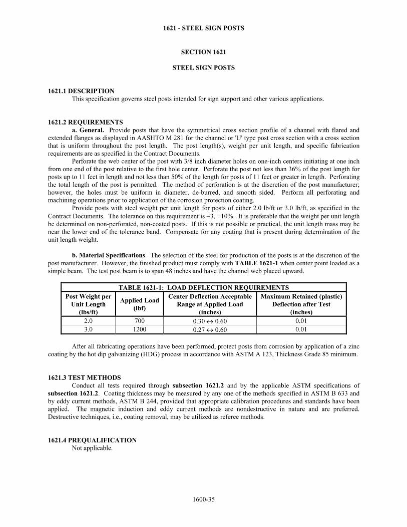
1621 - STEEL SIGN POSTS
SECTION 1621
STEEL SIGN POSTS 1621.1 DESCRIPTION This specification governs steel posts intended for sign support and other various applications. 1621.2 REQUIREMENTS a. General. Provide posts that have the symmetrical cross section profile of a channel with flared and extended flanges as displayed in AASHTO M 281 for the channel or 'U' type post cross section with a cross section that is uniform throughout the post length. The post length(s), weight per unit length, and specific fabrication requirements are as specified in the Contract Documents. Perforate the web center of the post with 3/8 inch diameter holes on one-inch centers initiating at one inch from one end of the post relative to the first hole center. Perforate the post not less than 36% of the post length for posts up to 11 feet in length and not less than 50% of the length for posts of 11 feet or greater in length. Perforating the total length of the post is permitted. The method of perforation is at the discretion of the post manufacturer; however, the holes must be uniform in diameter, de-burred, and smooth sided. Perform all perforating and machining operations prior to application of the corrosion protection coating. Provide posts with steel weight per unit length for posts of either 2.0 lb/ft or 3.0 lb/ft, as specified in the Contract Documents. The tolerance on this requirement is −3, +10%. It is preferable that the weight per unit length be determined on non-perforated, non-coated posts. If this is not possible or practical, the unit length mass may be near the lower end of the tolerance band. Compensate for any coating that is present during determination of the unit length weight. b. Material Specifications. The selection of the steel for production of the posts is at the discretion of the post manufacturer. However, the finished product must comply with TABLE 1621-1 when center point loaded as a simple beam. The test post beam is to span 48 inches and have the channel web placed upward.
TABLE 1621-1: LOAD DEFLECTION REQUIREMENTS Post Weight per
Unit Length (lbs/ft)
Applied Load (lbf)
Center Deflection Acceptable Range at Applied Load
(inches)
Maximum Retained (plastic) Deflection after Test
(inches) 2.0 700 0.30 ↔ 0.60 0.01 3.0 1200 0.27 ↔ 0.60 0.01
After all fabricating operations have been performed, protect posts from corrosion by application of a zinc coating by the hot dip galvanizing (HDG) process in accordance with ASTM A 123, Thickness Grade 85 minimum. 1621.3 TEST METHODS Conduct all tests required through subsection 1621.2 and by the applicable ASTM specifications of subsection 1621.2. Coating thickness may be measured by any one of the methods specified in ASTM B 633 and by eddy current methods, ASTM B 244, provided that appropriate calibration procedures and standards have been applied. The magnetic induction and eddy current methods are nondestructive in nature and are preferred. Destructive techniques, i.e., coating removal, may be utilized as referee methods. 1621.4 PREQUALIFICATION Not applicable.
1600-35
1621 - STEEL SIGN POSTS
1621.5 BASIS OF ACCEPTANCE Submit for approval to the project Engineer and MRC a Type A certification (certified mill test report), as specified in DIVISION 2600, that comply with subsection 1621.2. Submit the samples to the Engineer of Tests for evaluation and testing. Inspection of posts by field personnel for compliance with dimensional requirements and for the quality of the corrosion protection coating. The final disposition of all posts will be completed at the final destination as the result of inspection for the quality of workmanship and the delivery condition.
1600-36
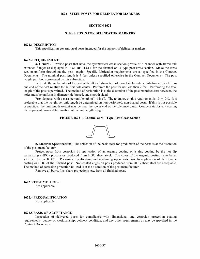
1622 - STEEL POSTS FOR DELINEATOR MARKERS
SECTION 1622
STEEL POSTS FOR DELINEATOR MARKERS 1622.1 DESCRIPTION This specification governs steel posts intended for the support of delineator markers. 1622.2 REQUIREMENTS a. General. Provide posts that have the symmetrical cross section profile of a channel with flared and extended flanges as displayed in FIGURE 1622-1 for the channel or 'U' type post cross section. Make the cross section uniform throughout the post length. Specific fabrication requirements are as specified in the Contract Documents. The nominal post length is 7 feet unless specified otherwise in the Contract Documents. The post weight per foot is governed by this subsection. Perforate the web center of the post with 3/8 inch diameter holes on 1 inch centers, initiating at 1 inch from one end of the post relative to the first hole center. Perforate the post for not less than 2 feet. Perforating the total length of the post is permitted. The method of perforation is at the discretion of the post manufacturer; however, the holes must be uniform in diameter, de-burred, and smooth sided. Provide posts with a mass per unit length of 1.1 lbs/ft. The tolerance on this requirement is −3, +10%. It is preferable that the weight per unit length be determined on non-perforated, non-coated posts. If this is not possible or practical, the unit length weight may be near the lower end of the tolerance band. Compensate for any coating that is present during determination of the unit length weight.
FIGURE 1622-1, Channel or ‘U’ Type Post Cross Section
b. Material Specifications. The selection of the basis steel for production of the posts is at the discretion of the post manufacturer. Protect posts from corrosion by application of an organic coating or a zinc coating by the hot dip galvanizing (HDG) process or produced from HDG sheet steel. The color of the organic coating is to be as specified by the KDOT. Perform all perforating and machining operations prior to application of the organic coating or HDG of the finished post. Non-coated edges on posts produced from HDG sheet steel are acceptable. The method of corrosion protection utilized is at the discretion of the post manufacturer. Remove all burrs, fins, sharp projections, etc. from all finished posts. 1622.3 TEST METHODS Not applicable. 1622.4 PREQUALIFICATION Not applicable. 1622.5 BASIS OF ACCEPTANCE Inspection of delivered posts for compliance with dimensional and corrosion protection coating requirements, quality of workmanship, delivery condition, and any other requirements as may be specified in the Contract Documents.
1600-37
1623 - STEEL PERMANENT DECK FORMS
SECTION 1623
STEEL PERMANENT DECK FORMS 1623.1 DESCRIPTION This specification governs the requirements for the steel utilized to fabricate permanent deck forms. 1623.2 REQUIREMENTS a. General. These forms are, by design, incorporated into the structure as an integral component. They contain the concrete during placement and add support to the deck of the finished structure. The design, dimensions, steel designation and thickness in inches, and specific fabrication requirements are to be as specified in the Contract Documents, or on the shop drawings. b. Material Specifications. Use steel in these forms that complies with ASTM A 653, structural steel (SS) and high strength low alloy steel (HSLAS), zinc coated to the Coating Designation G210 requirements. All HSLAS Type A and B Grades are acceptable. All SS Grades, except 50, are acceptable. Certain HSLAS require specific welding procedures. If welding of these steels is required, consult the steel producer. 1623.3 TEST METHODS Conduct all tests required by the applicable ASTM specifications of subsection 1623.2b. Coating thickness may be measured by any one of the methods specified in ASTM B 633 and by eddy current methods, ASTM B 244, provided that appropriate calibration procedures and standards have been applied. The magnetic induction and eddy current methods are nondestructive in nature and are preferred. Destructive techniques, i.e., coating removal, may be utilized as referee methods. 1623.4 PREQUALIFICATION Not applicable. 1623.5 BASIS OF ACCEPTANCE Receipt and approval of a Type D certification as specified in DIVISION 2600. Inspection and testing by field personnel of delivered permanent deck forms for compliance with dimensional and corrosion protection coating requirements, quality of workmanship, delivery condition, approval of required associated documentation, and any other requirements as may be specified in the Contract Documents. Coating thickness will be measured according to any of the procedures of subsection 1623.3.
1600-38
1624 - ZINC COATINGS
SECTION 1624
ZINC COATINGS 1624.1 DESCRIPTION This specification governs the requirements for zinc coatings applied to wrought and cast steel or cast iron products and components that are not specifically addressed within DIVISION 1600. 1624.2 REQUIREMENTS Wrought and cast steel products not specifically governed by DIVISION 1600 may be zinc coated in compliance with ASTM F 2329 for hot dip galvanizing. Cast iron products may be zinc coated by the hot dip galvanizing process in compliance with ASTM F 2329, also refer to SECTION 1613 and ASTM A 47, Supplementary Requirement S5, with regard to ferritic malleable iron castings. When hot dip galvanizing cast iron products, exercise caution to avoid galvanizing embrittlement. Wrought and cast steel or cast iron products may also be corrosion protected by the mechanical deposition of a zinc coating in compliance with ASTM B 695 as an alternative method, particularly when galvanizing embrittlement may be a factor. The Class required for ASTM B 695 is to be determined from the ASTM F 2329 minimum coating requirement for the product Class of Material. When corrosion protection by zinc coating is required, it must be specified in the Contract Documents. The method of coating, however, is to be at the discretion of the product manufacturer and selected from the alternatives addressed within this subsection. 1624.3 TEST METHODS The tests required for a product are to be based upon the consensus of the manufacturer and the KDOT. Conduct these tests as required by the applicable ASTM, or other material specifications of subsection 1624.2,. Coating thickness may be measured by any one of the methods specified in ASTM B 633 and by eddy current methods, ASTM E 376 (B 244 may also be useful as a technique guideline), provided that appropriate calibration procedures and standards have been applied. The magnetic induction and eddy current methods are nondestructive in nature and are preferred. Destructive techniques, i.e., coating removal, may be utilized as referee methods. 1624.4 PREQUALIFICATION Not applicable. 1624.5 BASIS OF ACCEPTANCE Inspection and testing by field personnel of delivered products and components for compliance with dimensional and corrosion protection coating requirements, quality of workmanship, delivery condition, approval of any required associated documentation, and any other requirements as may be specified in the Contract Documents. Measure coating thickness according to any of the procedures of subsection 1624.3.
1600-39
1625 - CAST BRONZE PRODUCTS
SECTION 1625
CAST BRONZE PRODUCTS 1625.1 DESCRIPTION This specification governs products for various applications cast from copper alloys generally classified as bronze. 1625.2 REQUIREMENTS a. General. Provide castings that comply with the design, dimensions, requirement for supplemental corrosion protection, and specific fabrication requirements as specified in the Contract Documents. Unless corrosion protection is specified, provide the cast products in the as-cast and as-machined condition. Bridge number plates are to be of the design and dimensions as specified in the Contract Documents and cast from a copper alloy identified in subsection 1625.2b. as a type to be utilized for general purpose castings. Relief cast the background of the plate relative to the letters, numbers, and border. Make the surfaces of the letters, numbers, and border lie in a single plane and polish them. Provide a relief from plane to background of about 1/8 inch. Make letters and numbers of the condensed Roman style approximately 1 ½ inches in height. Provide a matte non-reflective surface texture for the background. Coat the finished plates for corrosion protection with a clear organic coating that is durable and ultraviolet resistant. b. Material Specifications. The copper alloy utilized for bearing devices where the nominal contact pressure does not exceed 2500 psi, e.g., bridge bearing plates, complies with ASTM B 22, Copper Alloy UNS No. C91100. The copper alloy utilized for bearing devices where the nominal contact pressure does not exceed 1000 psi is to comply with ASTM B 22, Copper Alloy UNS No. C93700. Other copper alloys governed by ASTM B 22 may be utilized providing the KDOT grants prior approval. Use copper alloys for general purpose castings with a minimum copper content of 80%, and enhanced castability for the production of accurate castings with a high quality surface finish and a low level of discontinuities. Avoid beryllium copper alloys if at all possible. If they must be utilized, it is the manufacturer's responsibility to provide adequate warnings concerning the high toxicity of beryllium released to the atmosphere and potentially ingested during machining, grinding, welding, etc. operations. It is also the manufacturer's responsibility to document the precautionary procedures required to avoid exposure to beryllium if these operations must be conducted. 1625.3 TEST METHODS Not applicable. 1625.4 PREQUALIFICATION Not applicable. 1625.5 BASIS OF ACCEPTANCE Receipt and approval of a Type D certification as specified in DIVISION 2600. Inspection by field personnel of all products and components for compliance with dimensional and supplemental corrosion protection coating requirements when corrosion protection is specified, quality of workmanship, delivery condition, approval of the required associated documentation, and any other requirements as may be specified in the Contract documents.
1600-40
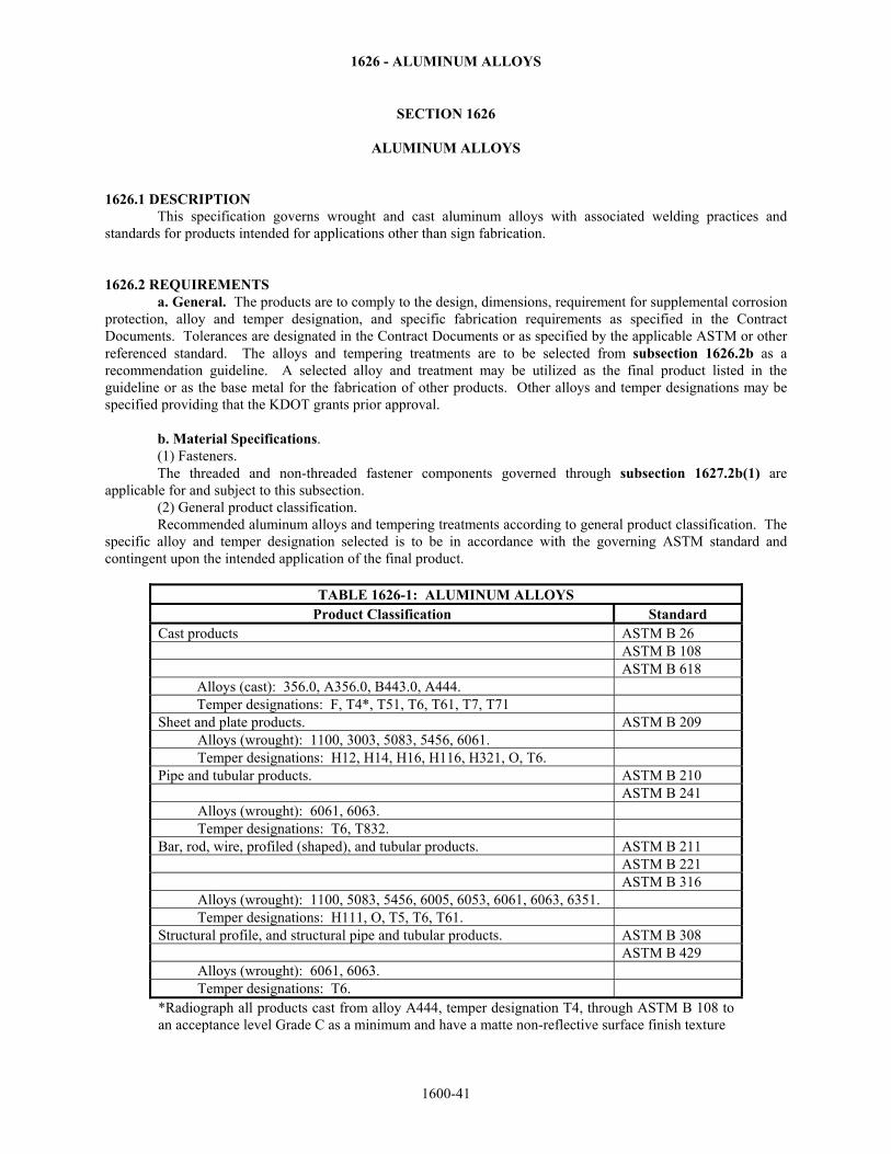
1626 - ALUMINUM ALLOYS
SECTION 1626
ALUMINUM ALLOYS 1626.1 DESCRIPTION This specification governs wrought and cast aluminum alloys with associated welding practices and standards for products intended for applications other than sign fabrication. 1626.2 REQUIREMENTS a. General. The products are to comply to the design, dimensions, requirement for supplemental corrosion protection, alloy and temper designation, and specific fabrication requirements as specified in the Contract Documents. Tolerances are designated in the Contract Documents or as specified by the applicable ASTM or other referenced standard. The alloys and tempering treatments are to be selected from subsection 1626.2b as a recommendation guideline. A selected alloy and treatment may be utilized as the final product listed in the guideline or as the base metal for the fabrication of other products. Other alloys and temper designations may be specified providing that the KDOT grants prior approval. b. Material Specifications. (1) Fasteners. The threaded and non-threaded fastener components governed through subsection 1627.2b(1) are applicable for and subject to this subsection. (2) General product classification. Recommended aluminum alloys and tempering treatments according to general product classification. The specific alloy and temper designation selected is to be in accordance with the governing ASTM standard and contingent upon the intended application of the final product.
TABLE 1626-1: ALUMINUM ALLOYS Product Classification Standard
Cast products ASTM B 26 ASTM B 108 ASTM B 618
Alloys (cast): 356.0, A356.0, B443.0, A444. Temper designations: F, T4*, T51, T6, T61, T7, T71
Sheet and plate products. ASTM B 209 Alloys (wrought): 1100, 3003, 5083, 5456, 6061. Temper designations: H12, H14, H16, H116, H321, O, T6.
Pipe and tubular products. ASTM B 210 ASTM B 241
Alloys (wrought): 6061, 6063. Temper designations: T6, T832.
Bar, rod, wire, profiled (shaped), and tubular products. ASTM B 211 ASTM B 221 ASTM B 316
Alloys (wrought): 1100, 5083, 5456, 6005, 6053, 6061, 6063, 6351. Temper designations: H111, O, T5, T6, T61.
Structural profile, and structural pipe and tubular products. ASTM B 308 ASTM B 429
Alloys (wrought): 6061, 6063. Temper designations: T6.
*Radiograph all products cast from alloy A444, temper designation T4, through ASTM B 108 to an acceptance level Grade C as a minimum and have a matte non-reflective surface finish texture
1600-41
1626 - ALUMINUM ALLOYS
(3) Welding of aluminum alloy products. Welding is to be conducted according to the recommendations of the ASTM standard that governs the product or basis metal and in accordance with the specifications and recommended procedures and practices of ANSI/AWS A5.10 and D1.2. 1626.3 TEST METHODS Conduct all tests required by the applicable ASTM or ANSI/AWS specification of subsection 1626.2b. 1626.4 PREQUALIFICATION Not applicable. 1626.5 BASIS OF ACCEPTANCE Receipt and approval of a Type B certification as specified in DIVISION 2600. Inspection by field personnel of all products and components for compliance with dimensional and supplemental corrosion protection coating requirements when corrosion protection is specified, quality of workmanship and delivery condition.
1600-42
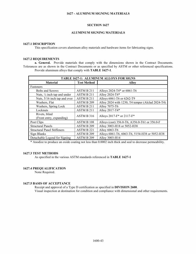
1627 - ALUMINUM SIGNING MATERIALS
SECTION 1627
ALUMINUM SIGNING MATERIALS 1627.1 DESCRIPTION This specification covers aluminum alloy materials and hardware items for fabricating signs. 1627.2 REQUIREMENTS a. General. Provide materials that comply with the dimensions shown in the Contract Documents. Tolerances are as shown in the Contract Documents or as specified by ASTM or other referenced specifications. Provide aluminum alloys that comply with TABLE 1627-1.
TABLE 1627-1: ALUMINUM ALLOYS FOR SIGNS Material Test Method Alloy
Fasteners Bolts and Screws ASTM B 211 Alloys 2024-T4* or 6061-T6 Nuts, ¼ inch tap and under ASTM B 211 Alloy 2024-T4* Nuts, 5/16 inch tap and over ASTM B 211 Alloys 6061-T6 or 6262-T9 Washers, Flat ASTM B 209 Alloy 2024 with 1230, T4 temper (Alclad 2024-T4)Washers, Spring Lock ASTM B 211 Alloy 7075-T6 Locknuts ASTM B 211 Alloy 2017-T4* Rivets, blind (Front entry, expanding) ASTM B 316 Alloys 2017-F* or 2117-F*
Post Clips ASTM B 108 Alloys (cast) 356.0-T6, A356.0-T61 or 356.0-F Structural Panels ASTM B 209 Alloy 3003-H18 or 5052-H38 Structural Panel Stiffeners ASTM B 221 Alloy 6063-T6 Sign Blanks ASTM B 209 Alloys 6061-T6, 6063-T6, 5154-H38 or 5052-H38 Detachable Legend for Signing ASTM B 209 Alloy 3003-H14 * Anodize to produce an oxide coating not less than 0.0002 inch thick and seal to decrease permeability.
1627.3 TEST METHODS As specified in the various ASTM standards referenced in TABLE 1627-1 1627.4 PREQUALIFICATION None Required. 1627.5 BASIS OF ACCEPTANCE Receipt and approval of a Type D certification as specified in DIVISION 2600. Visual inspection at destination for condition and compliance with dimensional and other requirements.
1600-43