division 13 special construction · size and configuration of tank: the dimensions of the...
TRANSCRIPT
DIVISION 13
SPECIAL CONSTRUCTION


13135-1
SECTION 13135
RADIO TELEMETRY SYSTEM (LICENSED) PART 1 - GENERAL 1.01 THE REQUIREMENT
A. The Contractor shall furnish, test, install and place in satisfactory operation the licensed radio telemetry system, with all spare parts, accessories, and appurtenances as herein specified and as shown on the Drawings.
B. A software radio path study has been completed using the parameters of the
equipment specified herein. The Contractor shall provide complete assistance to the Owner to obtain FCC licensing necessary to implement the wireless telemetry system as specified and shown on the Drawings. The Contractor shall retain a suitable firm to perform a radio frequency search and coordination. The Contractor shall complete all applications and acquire all necessary licenses in accordance with all applicable rules and regulations including, but not limited to, FCC Part 90. The Owner will pay all licensing fees and the cost of the frequency coordination.
C. The Contractor shall construct the system in accordance with all applicable FCC
rules as defined in 47CFR Part 90. In addition, the Contractor shall prepare and submit any required FAA permits or other documentation as required.
1.02 RELATED WORK SPECIFIED ELSEWHERE
A. Section 13300 – Instrumentation and Controls B. Section 16050 – Basic Electrical Materials and Controls
1.03 TOOLS, SUPPLIES AND SPARE PARTS
A. Tools, supplies and spare parts shall be provided as specified in Section 13300 Instrumentation and Controls. Where equipment is furnished under other Sections of the Specifications, spares requirements shall be as specified in those Sections. In addition, the following specific spare parts items shall be provided:
1. One of each type of printed circuit board used in telemetry equipment
furnished under this Contract. Complete devices shall be provided where individual circuit boards are impractical (e.g., radios).

13135-2
2. One of each type of miscellaneous hardware device for telemetry equipment furnished under this Contract (lightning arrester, power over Ethernet injector, set of connection glands, etc.).
3. One set of software and accessories for a notebook computer shall be
provided for diagnostic and programming functions. 4. One spare radio. 5. One spare antenna.
1.04 SUBMITTALS
A. In addition to submittals required under Section 13300 – Instrumentation and Controls, submit radio and antenna installation details for installations required under this Contract. The details shall include scaled drawings of the radio unit, antenna, antenna mounting hardware and support structures, enclosures, cabling, power supplies, connectors, ground clamps, fasteners, and lightning surge protectors. An equipment list shall be included identifying each component. Submit product literature for each component.
1.05 TELEMETRY SYSTEM EQUIPMENT LOCATIONS
A. The locations of the radio equipment and associated towers in the telemetry system are listed in the following table:
Location Coordinates Notes
Malcolm Road Gate 29 29 21.27N, 81 37 46.21W New 50’ tower PART 2 - PRODUCTS 2.01 GENERAL
A. The Contractor shall provide a licensed radio telemetry system that operates and is fully functional within the confines of the Owner's FCC license.
B. All communications equipment shall be installed in accordance with the
manufacturer's recommendations, FCC rules and regulations, and details on the Contract Drawings.
C. Radio telemetry equipment shall have a minimum of 30 minutes’ back-up power. D. All radio telemetry equipment power and signal lines that extend or are located
outside of an enclosed structure shall be protected from lightning and voltage surges
13135-3
in accordance with the requirements of Section 16050 –Basic Electrical Materials and Methods.
E. Although system configuration may be shown on the Control System Block Diagram,
the radio telemetry system shall be implemented based on actual installation conditions to provide a trouble-free and reliable transmission system.
2.02 ANTENNAS AND APPURTENANCES
A. Antennas shall be parabolic reflector type, with radome, rated for a minimum of 38 dBi gain and designed to operate in the 18 GHz frequency band. Antennas shall be provided with a waveguide connector suitable for mounting the radio directly to the back of the antenna. Net weight shall be no greater than 28 lbs. Antennas shall be Radiowaves model HP2-18, CommScope (Andrew) model VHLP2-18, or equal.
B. Antennas shall have a minimum operational wind speed rating of 90 mph. C. The Contractor shall provide and submit for approval a design for all new support
structures, including structure foundations, required for the radio telemetry system. The Contractor shall be responsible for obtain all geotechnical site information required to support the design.
1. Support structures shall be designed to withstand earthquake, wind and ice
loads in accordance with the Electronic Industries Association (EIA) Structural Standards for Steel Antenna Towers and Antenna Supporting Structures. Wind loads shall also be calculated in accordance with the State Building Code, except the basic wind speed used for calculating wind loads shall be 100 mph. The worst case loads from the EIA standards and the State Building Code shall be used for design.
2. Self-supporting towers shall be pre-fabricated of galvanized solid steel
members, as manufactured by PiRod, Inc., or equal. No welded supports shall be used on storage tanks. Only bolted stainless steel mountings shall be used, as manufactured by Tesco, Decibel Products, or equal.
D. Antennas shall be installed on existing or new support structures as specified and
shown on the Drawings. Antennas shall be installed with mounting hardware as recommended by the antenna manufacturer to adapt to the supporting structure.
2.03 LICENSED RADIO TRANSCEIVERS/MODEMS
A. Licensed radio transceivers shall use frequency modulation to transmit and receive telemetry data. The transceivers shall be completely compatible with the control and information system's hardware and communication protocols.
13135-4
B. Licensed radio transceivers shall be Solectek SkyWay-CM Series, GE MDS Intrepid
HC OIP, BridgeWave EtherFlex μWave ANSI, or equal. Licensed radios shall have the following operation and performance specifications:
1. Environmental
a. Temperature Range: -30°C to +55°C
b. Ingress Protection: IP66 or better
2. Power Supplies
a. Radio: Power over Ethernet
b. PoE Injector: 48 VDC
c. Maximum Power Consumption: 58 Watts 3. General Radio Specifications (Microwave)
a. Frequency Band: 17.7 to 19.7 GHz
b. FDD Spacing to 1560 MHz
c. Modulation Support: up to 256QAM
d. Ports: 1 x RJ-45 10/100/1000 Base-T for data, 1 x RJ-45 10/100 Base-T for network management
e. IP diagnostics included
f. Shall support IEEE 802.1Q (VLAN), IEEE 802.1p (QoS), IEEE 802.1ad (Q in Q)
4. Transmitter Specifications
a. Frequency Stability: +/- 7 PPM
b. Transmitter Output Power: 25 dBm, modulation dependent
c. Carrier Power Accuracy: Normal +/- 2 dB
d. Bandwidth: 10 – 50 MHz
e. Data Throughput: minimum 100 Mbps @256QAM
f. Latency: 150 μSec, configuration dependent
5. Receiver Specifications
a. Frequency Stability: +/- 7 PPM

13135-5
b. RF Sensitivity: -67dBm @256QAM
c. RSSI Accuracy: +/- 2 dB
B. All radio units shall be of the same manufacturer and model, and have the same operation and performance requirements.
PART 3 - EXECUTION 3.01 REQUIREMENTS
A. After the radios have been installed and configured, the instrumentation subcontractor shall optimize the antenna alignment for signal strength.
B. The instrumentation subcontractor shall test the following items and make all
necessary adjustments:
1. Supply voltage
2. Regulated voltage (In keyed and de-keyed positions)
3. Signal strength
4. Software revision
5. Hardware revision
C. Refer to Section 13300 for additional requirements.
END OF SECTION


13205-1
SECTION 13205
PRESTRESSED CIRCULAR CONCRETE TANKS PART 1 - GENERAL 1.01 DESCRIPTION A. Scope of Work 1. Requirements specified in Conditions of Contract and Division 1: General
Requirements form a part of this Section. Provide for the design and construction of the following tanks: two (2) 2.0 MG potable water ground storage tanks. Prestressed concrete tanks shall have domed top and shall conform to the dimensions and locations shown on the Drawings. The tank construction company shall furnish all engineering services required for the preparation of design calculations and detailed design drawings, and furnish all materials, labor and equipment for the construction of the prestressed tank as shown on the Drawings and as specified herein.
2. The prestressed concrete tanks shall be of composite steel-shotcrete, wire-
wound, prestressed construction. The wire-wound prestressed composite wall shall include a shotcrete core wall in which a steel shell diaphragm of a height equal to the full wall height has been encased. All prestressing shall be done with high tensile wire permanently bonded to the tank wall. The tank floor shall be of concrete or shotcrete construction containing no less than 0.6 percent of reinforcing steel. The tanks shall be designed to prevent buoyancy under conditions of maximum groundwater elevation as presented in the geotechnical engineer’s report (Appendix B). The tanks are not within 100 year flood zone.
3. Foundations of the storage tank is to be prepared in accordance with the
geotechnical engineer’s recommendations in the geotechnical report (Appendix B).
B. Related Work Described Elsewhere: 1. Excavation, Backfilling and Compaction: Section 02220. 2. Cast-In-Place Concrete: Section 03300. 3. Concrete Unit Masonry: Section 04220. 5. Pipe and Tube Railings: Section 05521.

13205-2
6. Bar Gratings: Section 05533. 7. Fiberglass Reinforced Plastic Fabrications: Section 06600. 8. Painting: Section 09900. 9. Process and Utility piping, fittings, valves and accessories: Division 15. C. General Design 1. The GST shall be furnished complete and shall, at a minimum, include: all
inlets and stand pipes; outlets; overflows; drain pipes; ladders, hatches, and railings; roof ventilators; perimeter concrete ventilators; manways; liquid level indicators; and tank levels and transmitters.
2. The thickness of the core wall shall be calculated so as to accept the initial
compressive forces applied by prestressing, hydrostatic stresses induced by contents, and other applicable loads such as soil backfill and wind.
3. Backfill loads shall not be used in the design of the core wall to counteract
hydraulic loads or provide residual compression in the wall. 4. All prestressing shall be done with high tensile steel wire in which a
substantial allowance shall be made for loss of prestress due to shrinkage and plastic flow in the shotcrete and to relaxation in the steel wire and diaphragm.
5. Size and Configuration of Tank: The dimensions of the prestressed
circular concrete tanks including the floor slopes, sumps, tank diameters and vertical wall heights shall be as indicated on the Drawings.
6. Design of the prestressed tanks shall accommodate the differential and total settlement values reported in the geotechnical investigation provided in the appendix of these specifications.
D. The Contractor shall be responsible for coordinating all activities with the
prestressed concrete tank construction company required for a complete installation. Activities requiring extensive coordination would include but not be limited to shop drawing submittals, embedded items required to be installed during construction of the prestressed concrete tank. Construction of the prestressed concrete tank shall not commence until all key dimensions, equipment and pipe locations, and any other interdependent items are approved by the Engineer and any conflicts or ambiguities are resolved. It shall remain the Contractor's sole responsibility to resolve any errors or conflicts arising during construction due to improper coordination with the prestressed concrete tank construction company.

13205-3
1.02 QUALITY ASSURANCE A. Design Standards: Unless otherwise indicated, all materials, workmanship and
practices shall meet all requirements of the following standards, latest revisions. 1. Standard Building Code. 2. ACI 301: Specifications for Structural Concrete for Buildings. 3. ACI 318: Building Code Requirements for Reinforced Concrete. 4. ACI 506R: Guide to Shotcrete. 5. ACI 372R-03: Design and Construction of Circular Wire and Strand
Wrapped Prestressed Concrete Structures. 6. AWWA D110-13 or latest revision - Wire- and Strand-Wound, Circular,
Prestressed Concrete Water Tanks. 7. ASTM A821/A821M - Standard Specification for Steel Wire, Hard Drawn
for Prestressing Concrete Tanks. 8. ASTM A1008/A1008M - Standard Specification for Steel, Sheet, Cold-
Rolled, Carbon, Structural, High-Strength Low-Alloy and High-Strength Low-Alloy with Improved Formability.
9. ASCE Standard 7-05 - Minimum Design Loads for Buildings and Other
Structures. 10. ASTM C881/C881M - Standard Specification for Epoxy-Resin-Base
Bonding Systems for Concrete. 11. ASTM A416/A416M - Standard Specification for Steel Strand, Uncoated
Seven-Wire for Prestressed Concrete. 12. ASTM A884/A884M - Standard Specification for Epoxy Coated Steel
Wire and Welded Wire Reinforcement. 13. ASTM A185 - Standard Specification for Steel Welded Wire
Reinforcement, Plain, for Concrete. 14. ASTM A615 - Standard Specification for Deformed and Plain Carbon-
Steel Bars for Concrete Reinforcement.

13205-4
15. ACI 305R - Hot Weather Concreting. 16. ACI 306R - Cold Weather Concreting. 17. ACI 350 - Building Code Requirements for Environmental Engineering
Concrete Structures and Commentary. 18. ASTM C31/C31M - Test Methods for Making and Curing Concrete Test
Specimens in the Field. 19. ASTM C39/C39M - Test Method for Compressive Strength of Cylindrical
Concrete Specimens. 20. ASTM C231 - Standard Test Method for Air Content of Freshly Mixed
Concrete by the Pressure Method. 21. ASTM C143 - Standard Test Method for Slump of Hydraulic -Cement. 22. ASTM C172 - Standard Practice for Sampling Freshly Mixed Concrete. 23. ASTM C33/C33M - Specification for Concrete Aggregates. 24. AWWA C652 - Disinfection of Potable Water Storage Tanks. 25. ASTM D1056 - Standard Specification for Flexible Cellular Material. B. Qualifications and Experience of Tank Construction Company: The tank
construction company shall have the following qualifications and experience: 1. The Tank Construction Company shall specialize in the design and
construction of wire-wound circular prestressed composite steel-concrete tanks. The tank construction company shall give satisfactory evidence that it has the skill, reliability and financial stability to design, build and guarantee the tank in accordance with the quality required by these specifications. The tank construction company shall have at least ten (10) years experience in this specialty and shall have built completely in its own name in the past five years no less than ten (10) prestressed composite tanks of comparable size, which meet these specifications and are now demonstrating satisfactory service.
2. The tank construction company staff shall include a full-time Professional
Engineer Registered in the State of Florida having no less than ten (10) years experience in the design and field construction of circular prestressed composite tanks who will be the responsible engineer in charge of the

13205-5
work to be done. All Working Drawings and design calculations shall carry the seal of such Registered Professional Engineer.
3. Acceptable Tank Manufacturers: The tank shall be as manufactured by the
Crom Corporation, Gainesville, Florida, or Precon Corporation, Newberry, Florida.
C. Design Criteria: To compensate for bending moments and for shrinkage,
differential drying, and temperature stresses, the following reinforcing steel shall be incorporated in the core wall:
1. The top two (2) feet of core wall shall have not less than 1%
circumferential reinforcing. 2. The bottom three (3) feet of core wall shall have not less than 1%
circumferential reinforcing. 3. Inside Face: a. 26-gauge steel shell diaphragm continuous the full wall height,
without horizontal splices. b. Additional vertical and horizontal reinforcing steel bars as required
by design computations. 4. Outside Face: a. Vertical reinforcing steel: Minimum of #4 bars at 12-inch center to
center. b. Additional vertical and horizontal reinforcing steel bars as required
by design computations. 5. Allowable Tensile Stress fs 18,000 psi Yield Strength fy 40,000 psi 6. Design Loads: Wind loads, including uplift and overturning shall be as
required by the Florida Building Code and any local amendments to the Code ASCE-7, or shall be for 155-mph wind loading, whichever is greater.
7. Qualifications of Workmen: The foreman, nozzlemen and gunmen shall
be skilled in their duties and certified in accordance with the guidelines by ACI Committee 506 Certification as outlined in Publication CP-60, latest revision. The Contractor shall submit the names of the men performing the above duties, with a statement of certification as to their qualifications.

13205-6
Certification will be accomplished by a recognized authority such as ELF/FC&PA*, ACI, or approved equal.
*ELF - Engineering Laboratory Forum, Florida Institute
of Consulting Engineers FC&PA - Florida Concrete and Products Association
8. Design shall account for buried depth of the tank as shown on drawings.
9. Concrete reinforcement, wall thickness, and loading shall be as certified by a Florida P.E.
1.03 SUBMITTALS A. Shop Drawings: The Contractor shall submit a complete set of detailed shop
drawings signed and sealed by a Florida Registered Professional Engineer for the work to be done. Inside dimensions, pipe openings and provisions for mechanical equipment shall be maintained as established by the Engineer. Shop drawings must be approved before construction may begin.
B. Design Computations: The Contractor shall submit complete design
computations. The design shall be done under the direction of a Florida Registered Professional Engineer and shall be signed or sealed by name of the design engineer. The design computations shall include all components of the tank, including wall, cantilevered launders, floor and sumps, baffle wall, wall penetrations, pipe supports, the wall reaction to the bottom slab, and the loads imposed by concrete dome covers. The design shall include consideration of temperature differentials under various conditions, stresses at wire winding and completed stages with tank empty and full, flexure in walls and base, anticipated movement of base under circumferential wire stresses, special stresses at wire anchorages and a construction procedure listing in chronological order the various operations of construction. The design computations shall be submitted for approval at least 30 days before the materials are assembled at the job site.
C. Shop drawings shall be submitted showing complete details, dimensions,
materials, fastenings, anchorages and special details of wall reinforcement at attachment of accessories and details of interior launder construction.
D. If a sliding waterstop is used in the floor/wall joint, submit load/shear/deflection
data to support shear and deflection calculations for base of wall. Tests shall have been generated for the particular waterstop configuration proposed.
E. Submit to the Engineer a guarantee document as specified in Paragraph 1.04,
herein following tank construction.

13205-7
1.04 WARRANTY A. The tank construction company shall guarantee workmanship and materials on the
entire tank structure and all accessories (i.e. manholes, ladders, aluminum stairs, platforms, grating, hatches, vents, baffle wall, etc.), including shrinkage cracks and hardware, for a period of five (5) years from final completion. In case leakage or other defects appear within the five (5) year period, the tank construction company shall promptly make repairs at its own expense, upon written notice by the Owner that such defects have been found.
B. To satisfy the five-year guarantee, acceptable tank construction companies listed
under paragraph 1.02B.3. above shall be required to furnish a written company warranty for the five-year period.
C. Leakage is defined as damp spots or visible leaks, appearing on the exterior
surface of the tank, indicating the existence of minor leaks or leakage through the base slab, the source of which is from the inside of the tank. Leakage shall be determined by leakage testing as defined herein.
PART 2 - PRODUCTS 2.01 MATERIALS
A. General Design of the tank shall meet the requirements in AWWA D110-13, or latest revision, Standard for Wire and Strand Wound Circular, Pre-stressed Concrete Water Tanks.
B. The tanks are intended for storage of potable drinking water. Therefore, materials that come into contact with the contents of the tank shall be approved for use with potable water by the National Sanitation Foundation (NSF) in accordance with Standard 61.
C. The roof and sidewalls of all water storage structures must be watertight with no
openings except properly constructed vents, manholes, overflows, risers, drains, pump mountings, control ports, or piping for inflow and outflow.
D. The tank walls shall be thickened in various areas to accommodate anchor bolts for the level indicator, ladders, electrical control panels, and various accessories shown on the Drawings and specified herein.
E. Protection from trespassers such as locks on manholes and other necessary
precautions to prevent trespassing, vandalism and sabotage shall be provided.
13205-8
High strength, cut resistant locks or lock covers to prevent direct cutting of a lock shall be provided.
F. Concrete shall have a 28 day compressive strength of 4000 psi and shall be in conformance with the requirements of Section 03300: Cast-in-Place Concrete. Cement shall be Type II.
G. Shotcrete shall be in accordance with ACI Standard 506, latest revision, except as indicated otherwise herein. Proportions for all shotcrete shall be one part cement to 4 parts moist sand by weight, except that proportions of 1 to 3 shall be used for the cover coat on each side of the steel shell diaphragm and over the wire wrapping; these richer cover coats shall be at least 1/4-inch thick (measured from the outside of the wire for wire wrapping coat). Sand shall be composed of hard, strong, durable, uncoated grains of quartz in accordance with gradation limits in ACI 506, except that the fineness modulus may be reduced to 2.0.
1. Compressive strength (fg) shall be 4,000 psi or greater at 28 days. 2. Allowable compressive stress (fg) shall be determined by the formula
1,250 + 75t with 0.45 fg maximum where t is the core wall thickness. 3. Allowable compressive stress (fg) due to initial prestressing force shall be
0.50 fgi or less, with a minimum of 2,000 psi, where fgi is defined as compressive strength at time initial prestressing force is applied.
4. Cement shall be in accordance with the requirements of Section 03300:
Cast-in-Place Concrete. Cement shall be Type II. H. Prestressing Wire: 1. Cold drawn, high-carbon steel wire complying with ASTM A-821 Type B. 2. Wire size shall be 0.162-inch diameter (8 gauge) or larger, but no larger
than 0.250-inch. 3. Working stress for wire in the wall (fs) shall be 115,000 psi. 4. Allowable tensile stress before losses (fis) shall be 145,000 psi or no
greater than 0.70 fs. 5. Ultimate tensile strength (fsu) shall be 231,000 psi or greater. I. Reinforcing Bars:

13205-9
1. In conformance with ASTM A615, Grade 60, and with the requirements of Section 03300: Cast-in-Place Concrete.
2. Floor slab bar supports shall be reinforced steel bolster. J. Wire Fabric Reinforcement: 1. Welded wire fabric (WWF) shall conform to ASTM A185: Welded Wire
Fabric for Concrete Reinforcement. Wire fabric shall be electrically welded and not galvanized wire. Welded wire fabric shall be furnished in flat sheets, rolled WWF is not permitted.
2. Welded wire fabric supports shall be plastic bolsters with bar ties
galvanized. K. Steel tank shell diaphragm shall be cold rolled sheet, minimum 26-gauge,
conforming to ASTM A1008/A-109 for Commercial Quality Cold Rolled Steel, with a Class 2, rolled finish or approved equal.
L. PVC waterstops shall have minimum thickness of 3/8-inch in areas exposed to
hydraulic loads.
M. Epoxy
1. Epoxy Sealants:
a. Epoxy used for sealing the steel shell shall conform to the requirements of ASTM C 881.
b. Epoxy used for sealing the steel shell shall be, Type III, Grade 1,
and shall be a 100% solids, moisture insensitive, low modulus epoxy system.
c. When pumped, maximum viscosity of the epoxy shall be 10 poises
at 77°F. d. The epoxy sealants used in the tank construction shall be suitable
for bonding to concrete, shotcrete, PVC, and steel.
2. Bonding Epoxy:
a. Epoxy resins used for enhancing the bond between fresh concrete and hardened concrete shall conform to the requirements of ASTM C 881.
13205-10
b. Epoxy resins shall be a two-component, 100% solids, moisture-insensitive epoxy and shall be Type II, Grade 2.
2.02 ACCESSORIES A. Accessories to be provided with each 2.0 MG Potable Water Ground Storage
Tank are as follows: 1. Accessories
a. Two (2) access manholes with smooth nozzle sample taps. b. One (1) set of exterior aluminum stairs. c. Two (2) interior fiberglass ladders with TS safety rail. d. Four (4) precast concrete overflow outlets. e. fiberglass access hatch for dome access as shown in the Drawings. f. One (1) fiberglass dome vent. g. Anodized aluminum handrailing around the dome hatch openings
and around the tank dome perimeter. h. Three (3) dome probe curbs (as shown in the Drawings). i. Five (5) stainless steel pipe support brackets. j. CMU baffle wall. k. Fiberglass vortex plate where shown in the drawings. l. One (1) 1-inch wall sleeve with modular seals. m. Fiberglass liquid level indicator. Accessories shall be provided and installed by the prestressed Concrete Tank
Construction Company. Accessories shall be as specified below. Anchor bolts, nuts, and bolts for all accessories shall be Type 316 stainless steel (certified).
B. Access Manholes:
1. Two (2) access manholes shall be provided for the prestressed concrete storage tank. Manways shall be provided on the sidewall of the tank for access. The access manholes shall be located on the vertical wall of the tank, at the locations shown on the Drawings. Each of the two (2) manholes shall be elevated at least 24 inches above the tank, or covering sod, whichever is higher. Each manhole shall be fitted with a solid water tight cover which overlaps a framed opening and extends down around the frame at least two inches. The frame shall be at least four inches high. Each cover shall be hinged on one side, and shall have a locking device.
2. Each access manhole shall include a fabricated Type 316 stainless steel frame and a fabricated Type 316 stainless steel cover. The cover plate shall be suitably gasketed with a suitable neoprene gasket as necessary to

13205-11
provide permanent water tightness. The manhole shall have a waterstop and be sealed with epoxy on the inside perimeter to preclude leakage. Pack thorite between re-entrant angles in diaphragm to give smooth surface for taping and cover taping with thorite. The manhole opening shall be in the shape of a round-ended slot approximately 17-inches high and 52-inches long.
3. All bolting materials shall be ASTM A320, B8M, Class 2, Type 316
stainless steel, high strength bolts and nuts. Washers shall be Type 316 stainless steel. Nuts shall have a hardness that is lower than that of the bolts and the washers by a difference of 50 Brinnell hardness to prevent galling.
C. Aluminum Handrails, Platforms and Grating: Anodized aluminum platforms shall be designed to support the intended live and
dead loads with a minimum factor of safety of 2.0. The maximum deflection for platforms shall be limited to a maximum of 1:360 of the maximum span. Aluminum used for fabrication shall be structural aluminum shapes in accordance with Section 05533 – Bar Grating. Aluminum grating used for platforms shall be in accordance with Section 05533 – Bar Grating. Aluminum handrailing installed around the dome access hatch and the aluminum access platforms shall be a two rail type handrail system, with a 4-inch toe board. Handrailing shall be constructed of 1-1/2-inch (1.90" o.d.), Schedule 40 aluminum pipe, Alloy 6063-T6, in accordance with Section 05521 – Pipe and Tube Railing.
D. Fiberglass Ladders: Fiberglass ladders shall be completely fabricated of fiberglass reinforced plastic
(FRP) structural shapes. Ladder uprights shall be 2-inch square tubing with a 1/8-inch wall thickness and shall be spaced 18-inches apart. Supports shall be 3/8-inch by 2-inch Type 316 stainless steel bars bent to shape and shall be spaced not over 5 feet apart. Ladders shall be rigidly supported not less than 7-inches from adjacent surfaces and shall be secured to the shotcrete wall by 316 stainless steel bolts embedded in the shotcrete during construction of the wall. Rungs shall be not less than 1-inch diameter, solid fiberglass bars, spaced 12-inches on centers with the ends fitted into and bonded to the uprights with epoxy. Fiberglass shapes for ladder fabrication shall be in accordance with Section 06600 - Reinforced Plastic Fabrications. An approved ladder safety device with Type 316 stainless steel TS rail and two safety harnesses shall be provided with the ladder. The ladder, and safety device shall be designed, fabricated, and erected in accordance with Part 1910 of the Occupational Safety and Health Standards of the Department of Labor.

13205-12
E. Fiberglass Hatch Cover: A hatch shall be provided on the top of the tank. Fiberglass hatch covers shall be
fabricated of 1/4-inch thick laminated fiberglass. Laminated Fiberglass fabrications shall be in accordance with Section 06600: Fiberglass Reinforced Plastic Fabrications. Dimensions of the hatch cover shall be as shown on the Drawings. The hatch cover shall be mounted onto a precast concrete curb cast into the dome cover.
The oversized frame for the fiberglass cover shall lap over and down the side of
the precast concrete curb to provide weather-tightness. The fiberglass frame shall have an integrally fabricated curb for mounting of the access hatch. The access hatch shall lap over and down the side of the fiberglass frame curb to provide weather-tightness. The fiberglass frame and access hatch shall be gasketed with a suitable neoprene gasket to prevent the entrance of water and insects. The hatch cover shall have a smooth, even, snug bearing in the locked position. All frame anchor bolts, hinges, lock loop, fasteners and other hardware shall be Type 316 stainless steel. The fiberglass hatch cover shall conform to the applicable requirements of Part 1910 of the Occupational Safety and Health Standards of the Department of Labor.
F. Fiberglass Vent: Fiberglass vents shall be fabricated of 1/4-inch thick laminated fiberglass.
Laminated fiberglass fabrications shall be in accordance with Section 06600: Fiberglass Reinforced Plastic Fabrications. The vent shall be mounted onto a precast concrete curb cast into the dome cover. A neoprene gasket shall be provided between the concrete curb and the fiberglass vent to prevent the entrance of water and insects. The fiberglass vent shall have a throat opening of 50-inches in diameter. The vent area shall be adequate for air venting at tank fill and withdrawal rates of 30 MGD. To prevent the entry of birds, animals and insects, the vent throat area and vent rim openings shall be covered with 24x24 mesh, vinyl covered fiberglass screening. All vent anchor bolts, fasteners and other hardware shall be Type 316 stainless steel.
G. Precast Concrete Overflow Vents: Overflow outlets for domed tanks shall be precast concrete with 24x24 mesh,
vinyl covered fiberglass insect screen and fiberglass frame attached with Type 316 stainless steel bolts of the size and number required. The precast concrete overflow outlets shall be cast into the dome cover. Each overflow outlet shall be sized for a 4.0-MGD minimum outflow.
13205-13
H. CMU Baffle Wall: Design of the CMU baffle wall shall be the responsibility of concrete tank
manufacturer and shall match the dimensions and location shown in the Drawings. CMU shall be in accordance with Specification Section 04230 and coating shall be in accordance with Specification Section 09900. Design of the concrete tank floor by the concrete tank manufacturer shall account for additional loads from the CMU baffle wall.
I. Exterior Access Stairs:
T-6061 aluminum with hand rail, kick plates, and landings meeting all OSHA requirements. Stairs shall be designed with three flights and landings and shall be located approximately as shown in the drawings. Provide structural calculation signed and sealed by a Florida licensed Professional Engineer.
J. Liquid Level Indicator
The fiberglass liquid level indicator shall be a standard unit supplied by the Tank Construction Company. The indicator board and target shall be 1/4-inch thick laminated fiberglass. The indicator board shall be white with 4-inch high black numbers and divisions. The numbers and divisions shall be black resin that is integrally molded into the fiberglass laminate board. All anchor bolts, fasteners, cable and other hardware shall be Type 316 stainless steel.
K. Sampling Taps Smooth-nosed sampling tap(s) shall be provided to facilitate collection of water samples for both bacteriological and chemical analyses. The sample tap(s) shall be easily accessible. Refer to Drawings for locations.
PART 3 - EXECUTION 3.01 CONSTRUCTION A. Excavation and Compaction: Excavation and compaction prior to tank
construction shall be in conformance with the applicable requirements of Section 02200, Earthwork, and the foundation preparation recommendations in the geotechnical engineer’s report (Appendix B).

13205-14
B. Floor: 1. The concrete floor is to be designed to be compatible with the foundation
preparation specified in the geotechnical Engineer’s recommendations in the geotechnical investigation report (Appendix B).
2. Concrete membrane floors (4-inches thick) shall have a minimum thickness of 8-inches of concrete over all pipe encasements. The minimum percentage, 0.6 percent, of reinforcing steel applies to these thickened sections and shall extend a minimum of two (2) feet in to the adjacent 4-inches thick floor.
3. Floors shall be vibratory screeded to effect consolidation of concrete and
proper encasement of floor reinforcing steel. 4. The floor shall be sloped to drain with the finishing criteria stated in
Section 03300: Cast-in-Place Concrete, except that the finishing tolerance shall be 1/2-inch in 10 feet, as determined by a 10-foot straightedge placed anywhere on the slab in any direction. The floor shall have a light broom finish.
5. Floors shall be continuously water cured until tank construction is
completed. C. Core Wall: 1. The core wall shall be constructed of shotcrete, encasing a steel shell
diaphragm continuous the full wall height without horizontal splices. The shotcrete shall be placed in accordance with ACI 506 as outlined in ACI Certification Public CP-60: A Guide to Shotcrete, latest revision.
2. The thickness of the core wall shall be calculated so as to resist the initial
compressive forces applied by prestressing, backfill, and other applicable loads. The wall may taper uniformly on the outside face from top to bottom as required by design computations. In no case shall the core wall be less than 3-1/2-inch thick. Horizontal sections of the wall shall form true circles without flats, excessive bumps, or hollows.
3. To compensate for bending moments and for shrinkage, differential
drying, and temperature stresses, the following reinforcing steel shall be incorporated in the core wall, as a minimum:

13205-15
a. The top two (2) feet of core wall shall have not less than one percent circumferential reinforcing.
b. The bottom three (3) feet of core wall shall have not less than one
percent circumferential reinforcing. c. Inside Face: 1) Vertical reinforcing steel: minimum of #4 bars at 12-inches
center to center. 2) Additional vertical and horizontal reinforcing steel as
required by design computations. d. Outside Face: 1) Vertical reinforcing steel: minimum of #4 bars at 12-inches
center to center. 2) Additional vertical and horizontal reinforcing steel bars as
required by design computations. 4. Curing: a. Interior core wall shall be continuously water cured for a minimum
of 7 days or until prestressing starts. b. Exterior core wall shall be continuously water cured for a
minimum of 7 days or until prestressing starts. 5. Tolerances: a. Tank Radius: The maximum permissible deviation from the
specified tank radius shall not be greater than 0.1 percent of the radius or 60 percent of the core wall thickness, whichever is less.
b. Vertical Walls: Walls shall be plumb within 3/8-inch per 10 feet
of vertical dimension. D. Steel Shell Diaphragm:
1. The galvanized steel diaphragm used in the construction of the core wall shall be 26 gauge with a minimum thickness of 0.017-inches conforming to the requirements of ASTM A653/A653M. Weight of zinc coating shall be not less than G90 of Table 1 of ASTM A653/A653M. The diaphragm

13205-16
shall be formed with re-entrant angles and erected so that a mechanical key is created between the shotcrete and diaphragm. The diaphragm shall be continuous to within 3-inches of the top and bottom of the wall. Horizontal joints or splices will not be permitted. All vertical joints in the diaphragm shall be rolled seamed, crimped and sealed watertight using epoxy injection. In all tanks designed to use a waterstop at the floor/wall joint, the steel shell diaphragm shall be epoxy bonded to the waterstop.
2. All vertical joints in the diaphragm shall be sealed watertight by epoxy injection. This epoxy injection shall be carried out from the bottom of wall to the top of wall, using a pressure pumping procedure, after the steel shell diaphragm has been full encased, inside and outside with shotcrete. The epoxy sealant shall be suitable for bonding to concrete, shotcrete, and steel. The sealant shall conform to the requirements of ASTM C881, Type III, Grade 1, and shall be 100 percent solids, moisture insensitive, low modulus epoxy system. When pumped, maximum viscosity of the epoxy shall be 10 poises at 77 degrees Fahrenheit (°F).
3. The steel shell diaphragm design and the epoxy injection procedure shall
have been used and proven satisfactory in the ten (10) tanks required for the tank construction company's experience record.
4. No nail or other holes shall be made in the steel shell for erection or other
purposes except for inserting pipe sleeves, reinforcing steel, bolts, or other special appurtenances. Such penetrations shall be sealed with an approved epoxy sealant.
5. In all tanks designed to use a waterstop at the floor/wall joint, the steel
shell diaphragm shall be epoxy bonded to this waterstop.
6. The steel shell diaphragm shall be suitably supported by temporary braces to preclude movement during construction. If the steel shell diaphragm is warm when ready for applications, the steel surfaces shall be sprayed with water for cooling approximately 30 minutes or less before shotcreting and again a few minutes before shotcreting.
E. Shotcrete: 1. All shotcrete shall be placed in accordance with ACI 506, latest revision,
and shall be applied by or under direct supervision of experienced nozzlemen certified in accordance with guidelines by ACI Committee 506 as outlined in ACI Certification. Certification shall be accomplished by an independent testing laboratory.

13205-17
2. Shotcrete mixes, measured by weight, shall be: a. First coat on steel shell diaphragm and prestressing wire: One (1)
part cement to three (3) parts fine aggregate. b. All other shotcrete: One (1) part cement to four (4) parts fine
aggregate. 3. Each shotcrete layer shall be broomed prior to final set to effect
satisfactory bonding of the following layer. No shotcrete shall be applied to reinforcing steel or diaphragm which is encrusted with overspray.
F. Horizontal Prestressing: 1. Circumferential prestressing of the tank walls shall be achieved by the
application of cold-drawn, high-carbon steel wire complying with ASTM A821 Type B, placed under high tension. A substantial allowance shall be made for prestressing losses due to shrinkage and plastic flow in the shotcrete and due to relaxation in the prestressing steel wire.
2. Placement of the prestressing steel wire to the core wall shall be in a
continuous and uniform helix of such pitch as to provide in each lineal foot of core wall height an initial predetermined force and unit compressive stress equivalent to that shown on the approved shop drawings. Splicing of the wire shall be permitted only when completing the application of a full coil of wire, or when removing a defective section of wire.
3. Areas to be prestressed shall contain not less than ten (10) wires per foot
of vertical wall. A maximum of 24 wires per layer per vertical foot will be allowed. Shotcrete shall be used to completely encase each individual wire, and protect it from corrosion. To facilitate this encasement, the clear space between adjacent wires is to be no less than one (1) wire diameter.
4. Prestressing shall be accomplished by a machine capable of continuously
inducing a uniform initial tension in the wire before it is positioned on the tank wall. Tension in the wire shall be generated by methods not dependent on cold working or re-drawing of the wire. In determining compliance with design requirements, the aggregate force of all tensioned wires per foot of wall shall be considered rather than the force per individual wire, and such aggregate force shall be no less than that required by the approved Shop Drawings.

13205-18
5. No circumferential movement of the wire along the tank wall shall be permitted during or after stressing of the wire. The steel wire bands on the core wall shall be so placed that the prestress "working force" per foot of wall height shall exceed the hydraulic ring tension forces by not less than 5 percent. The "working force" shall be defined as the force determined by multiplying the area of steel wire by the unit wire stress after an allowance for losses of 20,000 psi has been made from the initial unit wire stresses. Such initial unit wire stress readings shall be made the same day the wire is placed, or if made later and after some stress losses have already occurred due to creep of wire, plastic flow and shrinkage of core wall, allowances shall be made for such losses. The clear space between adjacent wires is to be no less than one wire diameter.
G. Measurement of Wire Stress: 1. Equipment shall be supplied at the construction site by the tank
construction company to measure tension in the wire after it is positioned on the tank wall. This stress measuring equipment shall include: electronic, direct reading, stressometer or other device which can demonstrate not less than 2 percent accuracy; calibrated dynamometers; and a test stand to field verify the accuracy of the stressometer.
H. Exterior Covercoat: 1. After circumferential prestressing wires have been placed by the wire
winding machine, they shall be protected by encasement in shotcrete. This shotcrete encasement shall completely encapsulate each wire, and shall permanently bond the wire to the tank wall. The shotcrete over cover shall have a thickness of no less than 1-inch over the wire. When multiple layers of wire are required, shotcrete cover between layers shall be no less than 1/8-inch thick.
I. Wall Openings: 1. When it is necessary for a pipe, access manhole or other appurtenance to
pass through the vertical tank wall, the bottom of such appurtenance shall be no less than 18-inches above the floor slab. The prestressing wires required at the pipe or appurtenance elevation shall be distributed equally above and below the opening, leaving an unbanded strip around the entire tank. Ordinarily, unbanded strips shall have a vertical dimension of no more than 36-inches. All pipe sleeves passing through the wall shall be sealed to the steel shell diaphragm by epoxy injection.

13205-19
J. Shotcrete Finishes: 1. The interior and exterior vertical surfaces of the tank walls shall have a
fine, hairbrush broom finish to provide a finely textured, sandy type finish suitable for finish coating. Following finishing, all interior and exterior surfaces of the tank shall be lightly brushed to remove all loose particles of shotcrete or aggregate.
K. Curing of Shotcrete: The finish surfaces of walls shall be cured, starting as soon
as possible without damaging surface and not later than two (2) hours after placing, by any of the following methods:
1. Moist-mat cure or moist-cure for seven (7) days. 2. Moist-mat curing shall be moist-curing by covering with at least two (2)
layers of burlap, cotton mats, or other approved material. The mat shall be continuously sprayed or intermittently saturated by hosing not less than four (4) times during daylight hours. If intermittently saturated, the mat shall be saturated before 8:30 a.m. and within one and one-half hours of sundown. Saturating of the mat through the night hours will not be required except as may be directed during hot nights if humidity is low and the breeze is more than 5 mph.
3. Moist-curing shall be accomplished by keeping the surface of the concrete
continuously wet with water. Sprinklers or soaker hoses may be used to insure continuous complete water coverage of the concrete surfaces. The sprinklers, soaker hoses or other watering equipment shall be operated 24 hours a day for the duration of the curing period. The duration of the curing period shall be seven (7) days. To ensure that sprinkling water is not blown away by wind from its intended location, special attention shall be given to the number and location of sprinklers so that all concrete surfaces are kept continuously wet. The Contractor shall have personnel at the site check the operation of all wetting equipment, the equipment shall be checked out not less than once each daylight hour and once every four hours during the night hours. Daylight hours shall be considered to be from one hour after sunrise to one hour before sundown. The remainder of the day shall be considered night hours.
4. Curing during the multi-layered shotcrete construction: The following
curing procedures shall be used for any layer of shotcrete that will remain in place more than three (3) hours before the next layer of shotcrete is applied. During hot weather, to reduce cracks caused by quick drying shrinkage, each layer of shotcrete shall be moist-mat cured or moist-cured within one hour after application. The mat, if used, shall be kept moist
13205-20
until it is removed and shall not be removed until just before the next layer of shotcrete is applied. The mat shall be against the shotcrete surface enough to avoid circulation of warm air between the mat and the shotcrete. The exterior surface of the core wall (the surface to receive wire wrapping) shall not receive curing compound, but shall be continuously cured for at least seven (7) days using the moist-mat or moist-cured procedure. In hot weather, the surface of shotcrete shall be fogged as soon as possible after application before other curing methods are started to avoid quick loss of moisture from the fresh shotcreted surface.
L. Drain and Overflow Piping
1. Provide flapper or duckbill check valve with corrosion resistant screen.
Refer to the drawing detail for location and installation detail. 3.02 FIELD QUALITY CONTROL A. Shotcrete Compressive Testing: 1. All tests shall be performed by the tank manufacturer. Each test of
shotcrete compressive strength shall consist of the preparation and breaking of five (5) cylinders. The high and low strength cylinders shall not be counted and the strength of the test shall be the average compressive strength in pounds per square inch of the three (3) remaining cylinders.
2. If cylinders are made for determining when wire wrapping can begin, they
shall be stored at the site and cured the same as the applicable portion of the structure. All other cylinders shall be removed the next day and stored in a testing laboratory vault similar to standard concrete cylinders. The test cylinders shall be the same mix used in the permanent construction.
3. One test shall be made for each 50 cubic yard (cy) of concrete, but not less
than two (2) sets for the inside core wall, two (2) sets for the outside core wall and two (2) sets for the over coat. Capping and breaking of cylinders shall be done similarly to standard concrete cylinders and shall be done by a recognized testing laboratory approved by the Engineer.
B. Leakage Testing: 1. Prior to testing, clean exposed surfaces by thorough hosing and remove all
loosened matter and wash water from the structures. 2. Conduct testing before backfill is placed against walls and after all
concrete has attained the specified compressive strength.

13205-21
3. Fill hydraulic structures to be subjected to leakage tests with water to the
high liquid level line. Fill rate shall not exceed the tank manufacturer’s recommendations. Do not fill more than 10 feet of water depth per day, unless otherwise approved by the Engineer. Repair any running leaks which appear during filling before continuing. After the structure has been kept full for 48 hours, it will be assumed, for the purposes of the tests, that the absorption of moisture by the concrete in the structure is complete. Then, close all valves and gates to the structure and measure the change in water surface each day for a five-day period.
4. During the test period, examine all exposed portions of the structure, and
mark all visible leaks or damp spots. Repair such leaks or damp spots later. If the drop in water surface in a 24 hour period exceeds 1/20 of 1 percent of the normal volume of liquid contained in the structure, the leakage will be considered excessive.
5. If the leakage is excessive, drain the structure, repair leaks and damp spots,
refill the structure and again test for leakage. Continue this process until the drop in water surface in a 24 hour period, with the structure full, is less than 1/20 of 1 percent of the volume.
6. Evaporation and precipitation rates shall be independently measured as
part of the leakage test. 7. Make repairs and retest using the above procedures at no additional cost to
the Owner. 8. Apply specified coatings only after acceptance of leakage testing by the
Engineer. 3.03 PAINTING A. All piping, supports, and other ferrous metal surfaces shall be coated in
accordance with the applicable requirements of Section 09900: Painting. All interior concrete surfaces of tank walls and tank domes shall be coated prior to leakage testing in accordance with the applicable requirements of Section 09900: Painting. All interior surfaces of the storage tanks shall be coated with a coating system that is NSF-61 approved for use with potable water. All curing compounds that shall contact potable water shall be NSF approved. Ground storage tank surfaces shall be coated with the following:
13205-22
1. Ground storage tank interior (walls, floors, dome and CMU baffle wall):
a. Prime coat: one (1) coat Tnemec Series 140 Pota-Pox plus polyamide epoxy at 7.0 mils dft per coat.
b. Finish coat: two (2) coats Tnemec Series 140 Pota-Pox plus polyamide epoxy at 7.0 mils dft per coat.
2. GST exterior (dome and walls):
a. Two (2) coats Tnemec Series 156 Enviro-Crete modified waterborne acrylate at 5.0 mils dft per coat.
3.04 DISINFECTION
A. Disinfect tanks in accordance with Specification Section 15041 Disdinfection of Piping
nad Structures.
END OF SECTION

13216-1
SECTION 13216
FIBERGLASS REINFORCED PLASTIC TANKS PART 1 - GENERAL 1.01 DESCRIPTION A. Scope of Work: 1. This section covers the furnishing and installation of one (1) fiberglass
reinforced plastic (FRP) tank for the storage hydrofluosilicic acid and two (2) fiberglass reinforced plastic (FRP) tanks for the storage of sodium hypochlorite.
2. Tanks furnished and installed under this section shall be fabricated,
assembled, erected, and placed in proper operating condition in full conformity with drawings, specifications, engineering data, instructions, and recommendations of the fabricator unless exceptions are noted by the Engineer.
3. The Contractor shall coordinate the work between the suppliers of
equipment to be used with or connected to the tank to ensure that all required provisions for mounting the accessories are included.
B. Related Work Described Elsewhere:
1. Cast-in-Place Concrete: Section 03300.
2. Structural Steel Framing: Section 05120.
3. Painting: Section 09900.
4. Chemical Feed Systems: Section 11241.
5. Polyvinyl Chloride (PVC) Pressure Pipe and Fittings: Section 15064.
6. Schedule 80 Polyvinyl Chloride (PVC) Pipe, Fittings, and Valves: Section 15070.
7. Chemical Feed System Piping: Section 15090.
C. General Design (not applicable)

13216-2
1.02 QUALITY ASSURANCE A. Governing Standards: Except as modified or supplemented herein, all materials
and construction methods shall comply with the applicable provisions of the following standards:
1. ASTM C581, "Chemical Resistance of Thermosetting Resins Used in
Glass Fiber Reinforced Structures”. 2. ASTM C582, "Standard Specification for Contact-Molded Reinforced
Thermosetting Plastic (RTP) Laminates for Corrosion Resistant Equipment".
3. ASTM D3299, "Standard Specification for Filament-Wound Glass-Fiber
Reinforced Thermoset Resin Chemical-Resistant Tanks". 4. ASTM D4097, "Standard Specification for Contact-Molded Glass-Fiber
Reinforced Thermoset Resin Chemical-Resistant Tanks". 5. NSF/ANSI Standard 61, AWWA – Drinking Water System Components
6. Florida Building Code. 7. Fabricator's Quality Assurance Supervisor: Minimum of 3 years'
experience in the fabrication of fiberglass structures. 8. Designer: Registered Professional Engineer in Florida. 9. The tanks shall be furnished, coordinated, and tested by one supplier. The
system shall be completely shop-assembled, skid-mounted, and shop-tested prior to shipment.
10. The tanks shall be ASME RTP-1 certified. 1.03 SUBMITTALS A. Materials and Shop Drawings: 1. Complete drawings, details, and specifications covering the storage tanks
and accessories shall be submitted in accordance with Section 01340: Shop Drawings, Working Drawings and Samples.
2. The data shall include full information on basic materials and test data
confirming the chemical resistance of the proposed resins to the intended tank contents.

13216-3
3. The data shall also indicate the sizes of all major tank components
including tank diameter, wall thickness, overall length, nozzle details and locations, anchor bolt locations and details, and full information and details concerning field assembly and installation.
4. Fabricator's catalog information, descriptive literature, specifications, and
identification of materials of construction. Include complete resin system information.
5. Color chart showing available tank colors. Black tanks are not acceptable. 6. Detailed fabrication drawings. 7. Complete design calculations for tanks, supports, and appropriate
accessories. 8. Tank capacity chart indicating gallons for each inch of depth and
cumulative total from bottom. 9. Fabricator's detailed requirements for tank foundations. 10. Recommended bolt torques for all bolted FRP connections. 11. Recommendations for tank material selection and fabrication methods for
services indicated on the Tank Data Sheets included at the end of the Detailed Specifications.
12. Supporting documentation of Manufacturer’s certification to NSF/ANSI
Standard 61 – Drinking Water System Components for water treatment chemicals.
13. ASME RTP-1 Certification. 14. Certified test data on representative samples of standard laminate materials
which verify that their physical properties meet the requirements and service conditions specified. Include verification of structural design parameters.
15. Final Configuration of Tank Appurtenances: The final locations of tank
appurtenances including, but not limited to, nozzles, manways, pipe supports, anchor lugs, ladder, and handrail will be confirmed by the Engineer during review of Contractor's drawing submittals.

13216-4
B. Samples: Laminate sample representative of production quality of surface finish and visual imperfections.
C. Quality Control Submittals: 1. Fabricator's Certificate of Compliance with fabrication requirements. 2. Qualifications of fabricator's Quality Assurance Supervisor. 3. Copy of the fabricator's Quality Assurance Program. 4. Certification of Factory Testing. Submit factory test reports to the
Engineer. 5. Certification that the tank supports, and access nozzles have been
coordinated with the actual equipment being furnished. 6. Special shipping, storage and protection, and handling instructions. 7. Fabricator's written/printed installation and tank support instructions. 8. Manufacturer's Certificate of Proper Installation. 9. ASME RTP-1 Certified. D. Contract Closeout submittals: Service records for repairs performed during
construction. E. Additional Information 1. In the event that it is impossible to conform to certain details of the
specifications due to different manufacturing techniques, describe completely all nonconforming aspects.
F. Operating Instructions 1. Operating and maintenance manuals shall be furnished. The manuals shall
be prepared specifically for this installation and shall include all required cuts, drawings, equipment lists, descriptions, etc., that are required to instruct operation and maintenance personnel unfamiliar with such equipment. The number and special requirements shall be as specified in Section 01730: Operating and Maintenance Data.
2. A factory representative of all major component manufacturers, who has
complete knowledge of proper operation and maintenance, shall be

13216-5
provided for a minimum two (2) eight (8) hour days to instruct representatives of the Owner and the Engineer on proper operation and maintenance. With the Owner's permission, this work may be conducted in conjunction with the inspection of the installation and test run as provided under PART 3-EXECUTION. If there are difficulties in operation of the equipment due to the manufacturer's design or fabrication, additional service shall be provided at no cost to the Owner.
1.04 PRODUCT DELIVERY, STORAGE AND HANDLING A. The tanks and components shall be adequately protected during transportation, in
storage at the job site, and during subsequent installation and construction activities. Damaged units will be rejected and shall be replaced with undamaged units.
1.05 WARRANTY AND GUARANTEES A. The tank shall be warranted for 10 years from final completion to be free of
defects in material and workmanship. B. See Section 01740: Warranties and Bonds. PART 2 - PRODUCTS 2.01 GENERAL
A. The tanks shall be as manufactured by Plas-Tanks Industries, Inc., Belco Manufacturing Co., Inc. Diamond Fiberglass, or Midwestern Fabricators.
B. Tanks shall be manufactured from materials certified to NSF/ANSI Standard 61 for chemical storage.
2.02 MATERIALS AND EQUIPMENT A. Basic materials shall be as follows:
Resin Vinyl ester resins shall be Hetron 922 suitable for use with the specified chemicals, or approved equal. Color shall be selected by the Owner. Black tanks will not be allowed.
Reinforcement Glass fiber with a suitable coupling agent.

13216-6
Surfacing Mat Burlington Formed Fabrics "Nexus Veil", Nicofibers "Surmat 100", or equal.
Plastic Laminate In conformity with the applicable governing
standards. Exposed Metal ANSI Type 316 stainless steel, in services other
than fluoride and sodium hypochlorite. Hastelloy C in fluoride and sodium hypochlorite service.
Exposed Assembly and Bolts, Nuts, and Washers ANSI Type 316 stainless steel, in services other
than fluoride and sodium hypochlorite. Hastelloy C in fluoride and sodium hypochlorite service.
Protected Metal Carbon steel, ASTM A36, with fiberglass
reinforced plastic coating. B. Performance and Design Requirements
1. Conditions of Service: Each tank will normally be used to store the specified chemical at atmospheric pressure. The tanks shall be designed for the storage of the following liquid chemicals:
Tank Number 5-TK-01 4-TK-01, 4TK-02
Chemical Hydrofluosilic Acid Sodium Hypochlorite
Location Treatment Building Treatment Building
Max. Concentration by Weight
25 15
Chemical Specific Gravity
1.25 1.16
Max. Temp., Degr. F 100 100
Min. Temp., Tank Contents, Degr. F.
Ambient Ambient
2. Design Criteria: a. Each tank shall be designed to withstand the hydrostatic head
which would result with the tank and fill line surcharged with the liquid chemical to 6 inches above the top of the tank.

13216-7
b. The tanks shall conform to the following requirements:
Tank Number 5-TK-01 4-TK-01, 4TK-02 Service Fluoride Bulk
Storage Sodium Hypochlorite
Storage Orientation Vertical Vertical Number of Units 1 2
Tank Number 5-TK-01 4-TK-01, 4TK-02 Nominal capacity, measured to invert of overflow pipe, gal
500 5,000
Max. Diameter, feet 6 9 Max. Height, feet 7 12
c. Each tank shall be designed in accordance with the applicable
design standards referenced herein. Design calculations shall be provided for each tank and shall be signed and sealed by a professional engineer registered in the State of Florida.
C. Fabrication and Manufacture 1. Manufacture a. The tanks shall be hand lay-up, spray-up, or filament wound
construction in accordance with the applicable governing standard. All tank shells shall be shop fabricated in a controlled environment by the manufacturer and no vertical seams shall be allowed. The finished laminate shall be constructed using a single generic type of thermoset resin throughout and shall not contain colorants, dyes, fillers, or pigments unless otherwise specified. Ultraviolet absorber shall be added to the resin used in the fabrication of tanks indicated on the drawings or specified to be suitable for installation in exposed, exterior locations.
b. The inner surface layer of the tanks shall consist of two resin rich
layers reinforced with surfacing mat and having a total combined thickness of not less than 110 mils.
c. Bracketed flat surfaces shall be provided on each tank for the
installation of a nameplate, and a certification plate. d. Minimum of four lifting lugs shall be provided on each tank as
required for handling and installation.
13216-8
e. For sodium hypochlorite, the cure system for the corrosion liner
shall be BPO/DMA with a four hour post cure at 180°F. For all other tanks and for structural layers on the sodium hypochlorite tanks, the initiator used shall be of the type, manufacturing origin, and amounts specified by the resin manufacturer. The resins and curing shall comply with FDA regulations 21 CFR 177.2420.
f. For sodium hypochlorite storage tanks, the inner surface of the tank
shall have double nexus veil of 20 mils with ECR banking for the corrosion liner. For all other chemical storage tanks, the inner surface of the tank shall have a single or double nexus veil of 20 mils as a minimum. Material used as reinforcing on the surface exposed to chemical attack shall be commercial grade chemical resistant glass fiber having a coupling agent.
g. The fluoride and sodium hypochlorite storage tanks shall be factory
air tested to a pressure of 5 psi for a duration of one hour. Any leaks detected during the testing shall be repaired by the manufacturer and the tank retested until no detectable leakage is observed.
3. Concrete Bases: a. The concrete bases for the tanks shall be constructed in accordance
with the provisions of Section 03300: Cast-in-Place Concrete and shall be level and smooth to the tolerances recommended by the tank fabricator. Concrete bases shall be coated in accordance with Sections 09900.
2.03 ACCESSORIES A. Accessories shall be provided on each tank as indicated on the drawings and as
specified herein. 1. Flanged Nozzles: a. Nozzles for connecting piping and accessories shall be provided on
each tank at the locations and of the sizes indicated on the drawings or specified herein.
b. Each nozzle shall be flanged, with flange diameter and drilling
conforming to ANSI B16.5, Class 150. Nozzles shall extend at least 4 inches from outside face of tank to face of flange. Gaskets for flanged connections shall be full-faced, 1/8-inch thick of

13216-9
suitable elastomeric material to resist the attack of the chemical lining being stored. Gaskets for sodium hypochlorite service shall be Viton. Gaskets for hydrofluosilicic acid service shall be Viton.
c. The level gauge mounting flange shall be above the maximum
liquid level recommended by the level sensor manufacturer. The length of the nozzle shall be as recommended by the level sensor manufacturer. The center line of the nozzle shall be at least 24 inches from the tank sidewall, fill nozzle, and other obstructions.
d. Flanged nozzles shall be fabricated of the same material as the tank
and shall be gusseted to the tank or otherwise reinforced in accordance with the governing standard.
e. Gaskets for flanged connections shall be full faced, 1/8-inch thick
of suitable elastomeric material to resist the attack of the chemical being stored.
f. Each tank shall be provided with the following flanged nozzles:
Nozzle Size, Location Quantity Connection Inches on Tank Fluoride Storage Tank - 5-TK-01 1 Fill 2 Top 1 Day Tank Feed 2 Side @ Bottom 1 Overflow 2 Top 1 Vent 6 Top 1 Level Transducer 6 Top 1 Site Glass 2 Side @ Top + Bottom 1 Drain 2 Side @ Bottom Sodium Hypochlorite Storage Tank - 4-TK-01 1 Fill 2 Top 1 Metering Pump Feed 4 Side @ Bottom 1 Overflow 2 Top @ Side 1 Vent 6 Top 1 Level Transducer 6 Top 1 Site Glass 2 Side @ Top + Bottom 1 Drain 4 Side @ Bottom

13216-10
Sodium Hypochlorite Storage Tank - 4-TK-02 1 Fill 2 Top 1 Metering Pump Feed 4 Side @ Bottom 1 Overflow 2 Top @ Side 1 Vent 6 Top 1 Level Transducer 6 Top 1 Site Glass 2 Side @ Top + Bottom 1 Drain 4 Side @ Bottom
2. Overflow and Drains: Chemical tank shall be provided with an overflow
and drain line of the size recommended by the manufacturer to provide means for draining the tank and to prevent spills in the event of an overflow.
3. Level Sight Gauge: Provide a 2-inch clear PVC level sight gauge where
indicated on the Drawings. Sight gauge shall be equipped with PVC isolation ball valves at the top and bottom connection to the tank. Provide drain with 2-inch ball valve as shown in the drawings.
4. Nameplates: Each tank shall be provided with a nameplate to identify the
use of the tank. The nameplates shall be of a plastic material with black engraved lettering one inch high and shall be mounted on the tank at a location acceptable to the Engineer.
5. Certification Plates: A plastic certification plate shall be installed below
each storage tank nameplate. The following data shall be included on the certification plate:
a. Name of tank fabricator. b. Date of manufacture. c. Product to be stored d. Maximum allowable concentration, specific gravity and
temperature of the specified chemical solution that can be stored safely.
e. Mechanical properties of the laminate. f. Resin designation. g. Equipment identification number shown listed herein.
13216-11
6. Lifting Lugs: Provide suitably attached for all tanks weighing over 100 pounds.
7. Anchor Bolts: Type 316, stainless steel bolts in services other than
fluoride and Hastelloy-C in fluoride service, sized by fabricator and at least 1/2-inch in diameter, or as shown and as specified in Section 05120, Structural Steel Framing.
8. Anchor Lugs: Anchor lugs shall be provided and shall be designed to
withstand all specified wind load conditions. No less than 8 anchor lugs shall be provided. Details of anchors shall be shown on fabrication Drawings. Anchor lugs shall be Hastelloy-C in fluoride and sodium hypochlorite service.
9. Ladders a. Provide ladders for tanks as shown on the drawings. Ladders shall
be constructed of FRP. Provide safety cages with ladders. Design ladders to meet OSHA standards: OSHA 2206, 1910.27.
b. Attach ladders to the tank to allow for tank expansion and
contraction due to temperature and loading changes. The mounting system shall be determined by the ladder material specified and the tank size requested. Connect top ladder mounts to integrally molded-in attachment lugs that allow for tank movement. Ladder mounts may be bolted or banded. Bolted mounts shall consist of a bracket bolted to the tank sidewall with 1/2-inch encapsulated bolts which allows tank movement without tank or ladder damage. The banded mounts shall consist of a bracket banded to the tank sidewall with 2-inch banding material which allows tank movement without tank or ladder damage. Attach ladders to the tank at the top ladder mount location only.
c. Provide work platform for access to top of the tanks as shown in
the Drawings. Work platform shall be constructed of FRP and designed to meet current OSHA specifications.
10. Each tank shall be provided with a 24-inch hinged manway located at the
top of the tank. 2.04 SPARE PARTS
A. Furnish the recommended spare parts properly boxed and labeled for each size and type provided for the project. At a minimum, furnish the following:

13216-12
1. Two (2) Gaskets for each size supplied under this Section. 2.05 QUALITY CONTROL A. Inspection of all products fabricated to this Specification is required prior to
shipment unless specifically waived in writing by the Engineer. This shall include:
1. Visual inspection to the requirements of ASTM C582-87 and ASTM
D2563-87. 2. Barcol Hardness measurements per ASTM D2583-87. 3. Acetone sensitivity test for all internal secondary bonds. 4. Glass content by ignition loss on three cutouts per ASTM D2584. 5. Hydrostatic Leak Test: a. Perform on each tank. b. Fill to top nozzle; allow to stand for 2 hours with no visible
leakage. B. Repairs authorized by the Engineer shall be reinspected before final acceptance
unless specifically waived. C. Identify and retain all cutouts. Engineer may select certain cutouts for testing for
physical properties of the laminate. D. Factory Test Reports: Certify, by signature, results of the following: a. Inspections. b. Results of hydrostatic testing. c. Test reports of physical properties of standard laminates.

13216-13
PART 3 - EXECUTION 3.01 PREPARATION (NOT APPLICABLE) 3.02 INSTALLATION A. The tanks shall be installed at the locations as indicated on the drawings. The
tanks shall be installed in accordance with the fabricator's recommendations, the requirements of the applicable governing standard, and to the satisfaction of the Engineer, and made ready for the installation of piping and other appurtenances as indicated on the drawings and specified under other sections. Grouting under the tank, if recommended by the tank fabricator, shall be done with nonshrinking grout as specified in Section 03300: Cast-in-Place Concrete.
3.03 INSPECTION AND TESTING A. After completion of installation, the tanks shall be filled with water to the top
access manhole opening and allowed to stand full for a period of not less than 48 hours. During testing, isolate tank by closing isolation valves where provided, flanged connections may be plugged by the installation of temporary blind flanges on the outside of the tank but shall not be blocked or plugged on the inside. All leaks or indications of leaks shall be repaired by the fabricator and made completely watertight. A leaking tank, upon repair, shall be retested to the satisfaction of the Engineer.
3.04 START-UP AND INSTRUCTION A. When installation has been completed and all connections have been made, all
tank surfaces, interior and exterior, shall be thoroughly cleaned as recommended by the fabricator and to the satisfaction of the Engineer. Abrasive cleaning agents shall not be used. The tank and wetted accessories shall be completely dried before being placed into service.
B. Provide fabricator's representative at site in accordance with Section 01650: Start-
Up for installation assistance, inspection and certification of proper installation and start-up assistance for specified component, subsystem, equipment, or system.
C. Manufacturer's Authorized Representative: Present at Work site designated by the
Contractor for the minimum person-days listed below, travel time excluded. 1. Services to include but may not be limited to: a. 1 person-day for installation assistance, inspection, and
certification of installation for each type of tank.

13216-14
2. Furnish assistance, inspection, and certification services at such times as requested by the Contractor.
END OF SECTION

13219-1
SECTION 13219
POLYETHYLENE CHEMICAL STORAGE TANKS PART 1 - GENERAL 1.01 DESCRIPTION A. Scope of Work: 1. This section covers the furnishing and installation of polyethylene
chemical tanks for the storage of the chemicals required for proper operation of the treatment facilities.
2. Tanks furnished and installed under this section shall be fabricated,
assembled, erected, and placed in proper operating condition in full conformity with drawings, specifications, engineering data, instructions, and recommendations of the fabricator unless exceptions are noted by the Engineer.
3. The Contractor shall coordinate the work between the suppliers of
equipment to be used with or connected to the storage tanks to ensure that all required provisions for mounting the accessories are included.
B. Related Work Described Elsewhere: Other sections directly related to work
covered in this section include the following:
1. Cast-in-Place Concrete: Section 03300.
2. Chemical Feed Systems: Section 11241.
3. Polyvinyl Chloride (PVC) Pressure Pipe and Fittings: Section 15064.
4. Schedule 80 Polyvinyl Chloride (PVC) Pipe, Fittings, and Valves: Section 15070.
5. Chemical Feed System Piping: Section 15090.
C. General Design (Not Applicable) 1.02 QUALITY ASSURANCE A. The tank manufacturer shall have a record of at least ten (10) installations during
the previous five (5) years for the tank sizes indicated. The manufacturer must be

13219-2
capable of furnishing names and telephone numbers of locations, which can be visibly inspected.
B. Factory Testing 1. Material Testing: Material taken from each tank shall be tested for the
following: Parameter Test Standard Value Impact ASTM D1998 120 ft-lb, min Gel, minimum ASTM D1998, 1/32-inch of inner wall: 65 percent outer wall: 85 percent total wall: 70 percent 2. Following fabrication, the tanks, including factory applied inlet and outlet
fittings, shall be hydraulically tested with water. The factory test shall compensate for the difference in specific gravity between the test water and chemical stored to simulate actual maximum operating pressures. Test methods shall include filling the tank with standpipes, raising the maximum water surface approximately 5 feet higher than the normal maximum tank level. The test duration shall be 24 hours. Following successful testing, the tank shall be emptied and dried prior to shipment.
3. An affidavit signed by the tank manufacturer shall be furnished indicating
that the factory tests have been performed and the indicated conditions have been met.
1.03 SUBMITTALS A. Materials and Shop Drawings 1. Complete drawings, details, and specifications covering the storage tanks
and accessories shall be submitted in accordance with Section 01340: Shop Drawings, Working Drawings and Samples.
2. The data shall include full information on basic materials and test data
confirming the chemical resistance of the proposed materials to the intended tank contents.
3. The data shall also indicate the sizes of all major tank components,
including tank diameter, wall thickness, overall length, nozzle details and locations, anchor bolt locations and details, support stands and full information and details concerning field assembly and installation.

13219-3
B. Additional Information 1. In the event that it is impossible to conform to certain details of the
specifications due to different manufacturing techniques, describe completely all nonconforming aspects.
2 Approved Materials: All materials that come into contact with the water
being treated or the finished water shall be on either the EPA or NSF lists of products approved for use in contact with potable water.
C. Operating Instructions 1. Operating and maintenance manuals shall be furnished. The manuals shall
be prepared specifically for this installation and shall include all required cuts, drawings, equipment lists, descriptions, etc., that are required to instruct operation and maintenance personnel unfamiliar with such equipment. The number and special requirements shall be as specified in Section 01730: Operating and Maintenance Data.
2. A factory representative of all major component manufacturers, who has
complete knowledge of proper operation and maintenance, shall be provided for a minimum two (2) eight (8) hour days to instruct representatives of the Owner and the Engineer on proper operation and maintenance. With the Owner's permission, this work may be conducted in conjunction with the inspection of the installation and performance test as provided under PART 3 - EXECUTION. If there are difficulties in operation of the equipment due to the manufacturer's design or fabrication, additional service shall be provided at no cost to the Owner.
1.04 PRODUCT DELIVERY, STORAGE AND HANDLING A. The tanks and components shall be adequately protected during transportation, in
storage at the job site, and during subsequent installation and construction activities. Damaged units will be rejected and shall be replaced with undamaged units at no expense to the Owner.
1.05 WARRANTY AND GUARANTEES A. The tank shall be warranted for ten (10) years from final completion to be free of
defects in material and workmanship. Warranty shall be prorated over the last eight (8) years.

13219-4
PART 2 - PRODUCTS 2.01 GENERAL Acceptable Manufacturers A. The tanks shall be as manufactured by Poly Processing, Assmann Corporation of
America, or Snyder Industries. 2.02 MATERIALS AND EQUIPMENT A. Basic materials shall be as follows: Tank Shell and Covers High density cross-linked polyethylene
construction with UV inhibitor. All tanks must be NSF approved.
Nozzles PVC, CPVC or Integrated Molded Flanged
(IMFO) outlet. Wetted and Non Wetted Bolts, Nuts, Washers and Hardware AISI Type 316 stainless steel, for services
other than fluoride and Hastelloy-C for fluoride service.
B. Performance and Design Requirements 1. Conditions of Service: Each tank will normally be used to store the
specified chemical at atmospheric pressure. The tanks shall be designed for the storage of the following liquid chemicals:
Tank Number 5-TK-02 Chemical Fluoride Location Treatment Building Max. Concentration Percent by Weight 25% Max. Specific Gravity 1.25 Max. Temp., Degrees F 100
Min. Temp. Tank Contents, Degrees F Ambient

13219-5
2. Design Criteria: a. Each tank shall be designed to withstand the hydrostatic head
which would result with the tank and fill line surcharged with the stored liquid chemical to 6 inches above the top of the tank.
b. The tanks shall conform to the following requirements:
Tank Number 5-TK-02 Tank Type Vertical Nominal Capacity measured to top of tank, (gal.) 50 Maximum diameter, inches 24 Max. tank height, inches 38
C. Fabrication and Manufacture 1. Fluoride Day Tank (5-TK-02) a. The tank shall be self-supporting of vertical cylindrical, seamless
construction. Day tank shall contain a flat bottom for mounting on the day tank scale specified herein. The tank shall be translucent with visible content level and white or cream in color. The tanks shall have capacities and dimensions as specified hereinbefore under Paragraph 2.02.
b. The tank shall be provided with a threaded access cap on the top of
the tank. c. The tank and tank scale shall be installed on a concrete base in
accordance with Section 03300. Base shall be level and smooth to the tolerances recommended by the tank manufacturer.
3. Testing a. Testing of all tanks shall be in accordance with subsections 1.02 B
and 3.03 of this specification.

13219-6
2.03 ACCESSORIES A. Accessories shall be provided on each tank as indicated on the Drawings and as
specified herein. 1. Nozzles: a. Nozzles for connecting piping and accessories shall be provided on
each tank at the locations and of the sizes indicated on the Drawings or specified herein.
b. Each nozzle for connecting piping and accessories 2-inch in
diameter and larger shall be flanged, with flange diameter and drilling conforming to ANSI B16.5, Class 150. Nozzles shall extend at least 3 inches from outside face of tank to face of flange. Gaskets for flanged connections shall be full face; 1/8 inch thick of suitable elastomeric material to resist the attack of the chemical being stored. Gaskets for fluoride service shall be Viton.
c. Nozzles for connecting piping and accessories less than 2-inches in
diameter shall be female NPT extending at least 2 inches from the outside face of the tank.
d. Each tank shall be provided with the following nozzles with the
orientation as shown on the Drawings:
Nozzle Location Quantity Connection Size, Inches on Tank
Fluoride Day Tank (5-TK-02)
1 Fill 1 Top 1 Overflow 2 Side @ Top 1 Feed Pump Suction/Drain 1 Side @ Bottom 1 Vent 2 Top
2. Vents: The chemical tanks shall be provided with a vent as shown on the
Drawings to prevent drawing a vacuum inside the tank during pumping or draining. Outside the vent shall be equipped with an insect screen of material compatible with the chemical stored.
3. Nameplates: Each tank shall be provided with a nameplate to identify the
chemical stored. The nameplates shall be of a plastic material with engraved lettering one inch high and shall be mounted on the tank at a

13219-7
location acceptable to the Engineer. The chemical designation to be engraved on the nameplate shall be as specified herein.
4. Certification Plates: A plastic certification plate shall be installed below
each storage tank nameplate. The following data shall be included on the certification plate:
a. Name of tank fabricator. b. Date of manufacture. c. Product to be stored. d. Maximum allowable concentration, specific gravity and
temperature of the specified chemical solution that can be stored safely.
e. Equipment identification number shown listed herein. 5. Gaskets for nozzles and tank cover flanges shall be supplied by the tank
manufacturer and be of an elastomeric material compatible with the chemical to be stored. Gaskets for fluoride service shall be Viton.
6. Day Tank Scales: Provide chemical scales suitable for the service intended
for each day tank where shown on the drawings. The chemical scale shall be of the digital readout/electronic single load cell type. The scale platform shall be sized to accept the tank size for which it is intended and shall be equipped with four (4) adjustable hold down lugs to increase lateral stability. The platform scale coating system shall be a minimum dry thickness of 80 mils and shall be resistant to moisture, chemicals, abrasion, impact, and UV light. Each day tank scale shall be equipped with a 4-20 mA output signal with a remote mounted LCD indicator. The indicator shall be housed in a NEMA 4X, UL approved enclosure with a power requirement of 120 volts. The indicator display shall give the operator the ability to monitor the chemical by weight (lbs) or volume (gallons) and shall display the percent (0-100) of net contents. The indicator shall output net weight via a 4-20mA signal and full scale output shall be user adjustable via the keypad. The indicator shall have four adjustable set points to display low or high level conditions on the indicator. Day tank scales shall be Force Flow Chem-Scale, or approved equal.

13219-8
2.04 SPARE PARTS
A. Furnish the recommended spare parts, properly boxed and labeled for each size and type provided for the project. At a minimum, furnish the following:
1. Two (2) Gaskets for each size supplied under this Section.
2.05 QUALITY CONTROL A. Contractor shall follow Manufacturer's and Supplier's product quality control
specifics as required for this project. PART 3 - EXECUTION 3.01 PREPARATION (Not applicable) 3.02 INSTALLATION A. The tanks shall be installed at the locations as indicated on the drawings. The
tanks shall be installed in accordance with the fabricator's recommendations, the requirements of the applicable governing standard, and to the satisfaction of the Engineer, and made ready for the installation of piping and other appurtenances as indicated on the drawings and specified under other sections. Grouting under the tank, if required to level the tank support stand, shall be done with non-shrinking grout as specified in Section 03300: Cast-in-Place Concrete.
3.03 ONSITE INSPECTION AND TESTING A. After completion of installation, the tanks shall be filled with water to the top
overflow opening and allowed to stand full for a period of not less than 48 hours. During testing, flanged or threaded connections may be plugged by the installation of temporary blind flanges or threaded plugs on the outside of the tank but shall not be blocked or plugged on the inside. All leaks or indications of leaks shall be repaired by the fabricator and made completely watertight. A leaking tank, upon repair, shall be retested to the satisfaction of the Engineer.
B Cleaning: When installation has been completed and all connections have been
made, all tank surfaces, interior and exterior, shall be thoroughly cleaned as recommended by the fabricator and to the satisfaction of the Engineer. Abrasive cleaning agents shall not be used. The tank and wetted accessories shall be completely dried before being placed into service.

13219-9
3.04 START-UP AND INSTRUCTION A. A representative of the manufacturer shall certify in writing that the tank has been
installed in accordance with the Manufacturer's recommendations. Certification shall be submitted.
END OF SECTION


13300-1
SECTION 13300
INSTRUMENTATION AND CONTROLS PART 1 – GENERAL 1.01 SUMMARY
A. The Contractor shall furnish, install and place into service operating process instrumentation, control systems and panels including accessories, related to this facility, all as shown on plans and specified herein.
1. The instrument contractor is responsible to provide completed panels that
are clean, functional and present a professional workman-like appearance. Field devices/equipment shall be provided with sunshields. Sunshields shall be rated for the area in which it will be constructed, unless otherwise noted, sunshields shall be rated NEMA-4X.
2. All wires in control panels must be permanently tagged and shown on the
as-built drawings. This includes all spare wires and cables. Spare cables are to be taped and left coiled in the panels for future use. Cable and wire numbers are to be assigned by the contractor, documented and controlled to prevent duplicate numbers. The contractor shall turn over to the owner, at the project conclusion, a cable and wire list showing assigned numbers and their physical location in the plant.
3. See electrical drawings and specifications for additional work required of the
instrument contractor as part of this project.
4. Provide and install new PLC control panels for the new Treatment Building, Wells (6), and Generator Switchboard including Schneider-Electric Modicon M580 PLC, input-output cards, fiber optic communication, as shown on drawings and as described in the specifications complete in place. All new control panels shall be included in the fiber loop. A break in the fiber loop shall not hinder any new control panel from communicating with SCADA. The Generator Switchboard shall be connected to the main SCADA system via Modbus Ethernet protocol.
5. Contractor shall provide PLC logic for all new PLC systems according to the
Orange County Standard Naming and Tag numbering system. Contractor shall closely coordinate with Owner and Engineer and inform any deviation and get approval from Owner.
6. Refer to “System Architecture” from I-drawings for the new PLC network.
All PLC panels shall use I/O scanning for program communication. Program 30 spare addresses into the I/O scanner.

13300-2
7. Contractor shall include, as part of the bid, factory level training course for the Owner from Belden for the Ethernet Switch Models to be supplied. Contractor shall pay all travel with perdiem and lodging for two individuals from Orlando, Florida to the training site for the duration of the training. Contractor shall also obtain the onsite training from the Hirschmann system integrator for at least four technicians from the Owner for four hours related to the devices installed. Contact information for Hirschmann is Paul Schonoff, office: 561-463-8577, [email protected].
8. Contractor shall configure the existing iHistorian Server Computer
located at the Eastern Regional Water Supply Facility to collect and store the data. Coordinate with Owner and provide for amount of tags that will be collected and stored at Eastern Regional Water Supply Facility.
B. Work Includes: Engineering, furnishing, installing, calibrating, adjusting, testing,
documenting, starting up, and OWNER training for a complete Instrumentation and Control System.
Major parts are:
1. Instrumentation including primary elements, transmitters, and control devices.
2. Control Panels. 3. PLC and I/O Rack Control Panels 4. Software and Licensing 5. Acceptance Testing, including 30-day system acceptance test.
C. Instrument and Control (I&C) Supplier work scope: 1. For I&C equipment and ancillaries provide the following: a. Complete detail design. b. Required Submittals. c. Equipment and ancillaries.
d. Instructions, details, and recommendations to, and coordination with, Contractor for proper installation.
e. Verify readiness for operation. f. Verify the correctness of final power and signal connections. g. Adjusting and calibrating. h. Starting up. i. Testing and coordination of testing. j. Training. 2. Verify following work not by I&C Supplier is provided: a. Correct type, size, and number of signal wires with their raceways. b. Correct electrical power circuits and raceways.

13300-3
c. Correct size, type, and number of I&C related pipes, valves, gates, fittings, and tubes.
d. Correct size, type, materials, and connection of process mechanical piping for in-line primary elements.
3. For equipment not provided under I&C Supplier, but directly connected to
equipment required by I&C Supplier: a. Obtain from Contractor, manufacturer’s information on
installation, interface, function, and adjustment b. Coordinate with Contractor to allow required interface and
operation with I&C System. c. For operation and control, verify that installations, interfacing
signal terminations, and adjustments have been completed with manufacturer’s recommendations.
d. Test to demonstrate required interface and operation with I&C System.
e. Examples of items in this category, but not limited to the following:
1) Valve operators, position switches, and controls. 2) Chemical feed pump and feeder speed/stroke controls. 3) Automatic samplers. 4) Motor control centers. 5) Adjustable speed drive systems. 6) Motor operated gates. f. Examples of items not in this category: 1) Internal portions of equipment provided under Division 16,
Electrical, that are not directly connected to equipment under I&C System.
2) Internal portions of I&C Systems provided as part of package systems and that are not directly connected to equipment provided under I&C System.
4. Wiring external to equipment provided by I&C Supplier: Special control and communications cable: Provided by I&C Supplier. D. Software Engineering work scope:
1. Configuration of PLCs, including:
a. Correct I/O mapping and scaling. b. Ladder logic implementing defined control strategies.
13300-4
c. SCADA interface mappings. d. Specifications/documents including: System External
Specification, System Internal Specification, I/O Checklist, Factory Acceptance Test Plan, and Site Acceptance Test Plan.
e. As-built documentation
2. Start-up support, including system testing.
3. System training. a) A minimum of two 8 hour days
4. Computer based SCADA system (G.E. Proficy/iFix. Version 5.8 or
latest version used by Owner.) No alternate shall be accepted.
1.02 SINGLE INSTRUMENT SUPPLIER
A. The Contractor shall assign to the Single Instrument and Control (I&C) supplier full responsibility for the functional operation of all new instrumentation systems. The Contractor shall have said supplier perform all engineering necessary in order to select, to furnish, to program, to supervise installation, to connect, to calibrate, to place into operation all sensors, instruments, alarm equipment, control panels, accessories, and all other equipment as specified herein. The I&C supplier shall have a maintenance/service office within a 150 mile radius of the project.
B. The single instrument and controls supplier shall demonstrate his ability to
successfully complete projects of similar sizes and nature. Provide references (including phone number and contact name) for at least three projects successfully completed in which the following tasks were performed: system engineering, documentation including panel assembly, schematics and wiring diagram, programming, field testing, calibration and start-up, operator instruction and maintenance training.
The foregoing shall enable the Contractor and the Owner to be assured that the
full responsibility for the requirements of this Section shall reside in an organization which is qualified and experienced in the water management field and its process technology on a functional systems basis.
The single I&C supplier shall have a UL approved shop and shall build all panels according to UL 508A.
Instrumentation and Controls supplier (System Integrator I&C Equipment
Supplier) shall be either Curry Controls Company or Revere Control Systems, Inc.
C. The single software engineering supplier shall demonstrate his ability to successfully complete projects of similar sizes and nature. Provide references (including phone number and contact name) for at least three projects successfully
13300-5
completed in which the following tasks were performed: ladder logic programming, computer based SCADA system configuration, documentation, field testing, start-up, and operator instruction.
1.03 COORDINATION
A. Systems supplied under this section shall be designed and coordinated by Systems Supplier for proper operation with related equipment and materials furnished by other suppliers under other sections of these specifications, under other contracts, and, where applicable, with related existing equipment. All equipment shall be designed and installed in full conformity with the drawings, specifications, engineering data, instructions, and recommendations of the manufacturer, and the manufacturer of the related equipment. All coordination and communications for the package control systems and other controls not supplied by the Systems Supplier shall be through the Systems Supplier.
1.04 INSTALLATION WORK
A. Nothing in this part of the Specifications shall be construed as requiring the Contractor to utilize personnel supplied by his assigned instrument manufacturer's organization, or any division thereof, to accomplish the physical installation of any elements, instruments, accessories or assemblies specified herein. However, the Contractor shall employ installers who are skilled and experienced in the installation and connection of all elements, instruments, accessories and assemblies; portions of their work shall be supervised or checked as specified in Part 3, herein.
1.05 PREPARATION OF SUBMITTAL OF DRAWINGS AND DATA
A. It is incumbent upon the Contractor to coordinate the work specified in these Sections so that a complete I&C system for the facility shall be provided and shall be supported by accurate Shop and record Drawings. As a part of the responsibility as assigned by the Contractor, the Single I&C supplier shall prepare and submit through the Contractor, complete organized Shop Drawings, as specified in Part 2.02, herein. Interface between instruments, motor starters, etc. shall be included in his Shop Drawing submittal.
B. During the period of preparation of this submittal, the Contractor shall authorize
direct, informal liaison between his Single I&C supplier and the Engineer for exchange of technical information. As a result of this liaison, certain minor refinements and revisions in the systems as specified may be authorized informally by the Engineer, but these shall not alter the scope of work or cause increase or decrease in the Contract Price. During this informal exchange, no oral statement by the Engineer shall be construed to give formal approval of any component or method, nor shall any statement be construed to grant formal exception to, or variation from these Specifications.

13300-6
C. In addition, I&C supplier/programmer shall also provide fully documented version
of PLC programming and HMI programming on the CD and hard paper copy. 1.06 ADDITIONAL TECHNICAL SERVICES
A. At no separate additional cost to the Owner, the Contractor shall provide the following services of qualified technical representatives of the Single I&C supplier (See Part 3, herein).
1. To supervise installation and connection of all instruments, elements, and
components of every system, including connection of instrument signals to primary measurement elements and to final control elements such as pumps, valves, and chemical feeders;
2. To make all necessary adjustments, calibrations and tests; and 3. To instruct plant operating and maintenance personnel on instrumentation.
This time shall be in addition to whatever time is required for other facets of work at the site, and shall be during the Owner's normal working days and hours.
4. To terminate and test all fiber optic cable and effected devices. 1.07 GUARANTEE A. The Contractor shall guarantee all equipment and installation, as specified herein,
for a period of three (3) years following the date of completion of the work. To fulfill this obligation, the Contractor shall utilize technical service personnel designated by the Single I&C supplier to which the Contractor originally assigned project responsibility for instrumentation. Services shall be performed within four (4) hours after notification by the Owner.
1.08 ADDITIONAL PROVISIONS A. The applicable provisions of the following Sections under Electrical Work shall
apply to work and equipment specified herein, the same as if stated in full, herein: 1. Codes and Standards 2. Equipment, Materials and Workmanship 3. Testing 4. Grounding 5. Equipment Anchoring 6. Conductor and Equipment Identification 7. Terminal Cabinets and Control Compartments 8. Process Control Devices

13300-7
1.09 NEWEST MODEL COMPONENTS A. All meters, instruments, and other components shall be the most recent field
proven models marketed by their manufacturers at the time of submittal of Shop Drawings unless otherwise specified to match existing equipment. All technical data publications included with submittals shall be the most recent issue.
1.10 INSPECTION OF THE SITE AND EXISTING CONDITIONS
A. The instrumentation drawings were developed from past record drawings and information supplied by the OWNER.
D. Before submitting a bid, visit the site and determine conditions at the site and at
all existing structures in order to become familiar with all existing conditions and instrumentation and control systems which will, in any way or manner, affect the work required under this Contract. No subsequent increase in Contract cost will be allowed for additional work required because of the CONTRACTOR’S failure to fulfill this requirement.
1.11 RELATED WORK A. Division 16 - Electrical B. Division 11 - Equipment C. Division 13 - Special Construction PART 2 - PRODUCTS 2.01 INSTRUMENTATION CRITERIA A. DESIGNATION OF COMPONENTS: In these Specifications and on the Drawings, all systems, meters, instruments, and
other elements are represented schematically, and are designated by numbers, as derived from criteria in Instrument Society of American Standard ANSI/ISA S5.1-1973. The nomenclature and numbers designated herein and on the Drawings shall be employed exclusively throughout Shop Drawings, data sheets, and similar materials. Any other symbols, designations, and nomenclature unique to the manufacturer's standard methods shall not replace these prescribed above, used herein, and on the Drawings.
B. ANALOG SIGNAL CHARACTERISTICS: Signals shall be electrical, as indicated herein, and shall vary in direct linear
proportion to the measured variable, except as noted. Electrical signals outside

13300-8
control panel(s) shall be 4 to 20 milliamperes DC, except as noted. Signals within enclosures may be 1-5 volts DC.
C. MATCHING STYLE, APPEARANCE AND TYPE: All instruments to be panel mounted at the control panels shall have matching
style and general appearance. Instruments performing similar functions shall be of the same type, model, or class, and shall be of one (1) manufacturer.
D. ACCURACY AND REPEATABILITY: The overall accuracy of each instrumentation system or loop shall be as prescribed
in the Specifications for that system or loop. Each system's accuracy shall be determined as a probable maximum error; this shall be the square-root of the sum of the squares of certified "accuracy s" of certain designated components in each system, expressed as a percentage of the actual span or value of the measured variable. Each individual electronic instrument shall have a minimum accuracy of +0.7 percent of full scale and a minimum repeatability of +0.4 percent of full scale unless otherwise specified. Instruments which do not conform to or improve upon these criteria are not acceptable.
E. SIGNAL ISOLATORS, CONVERTERS AND POWER SUPPLIES: Signal isolators shall be furnished and installed in each measurement and control
loop, wherever required, to insure adjacent component impedance match or where feedback paths may be generated. Signal converters shall be included where required to resolve any signal level incompatibilities. Signal power supplies shall be included, as required by the manufacturer's instrument load characteristics, to insure sufficient power to each loop component.
F. ALTERNATIVE EQUIPMENT OR METHODS: Equipment or methods requiring redesign of any project details are not acceptable
without prior approval of the Engineer. Any changes inherent to a proposal alternative shall be at no additional cost to the Owner. The required approval shall be obtained in writing by the single I&C Supplier through the Contractor prior to submittal of Shop Drawings and data. Any proposal for approval of alternative equipment or methods shall include evidence of improved performance, operational advantage and maintenance enhancement over the equipment or method specified, or shall include evidence that a specified component is not available. Otherwise, alternative equipment (other than direct, equivalent substitutions) and alternative methods shall not be proposed.

13300-9
2.02 DETAILED SYSTEMS DRAWINGS AND DATA A. CONTENT: The Contractor shall submit detailed Shop Drawings and data prepared and
organized by the Single I&C supplier in accordance with Division 1, Shop Drawings, Working Drawings, and Samples. These Drawings and data shall be submitted as a complete bound package at one time within 80 calendar days after date of Notice to Proceed and shall include:
1. Drawings showing definite diagrams for every instrumentation loop
system. These diagrams shall show and identify each component of each loop or system using legend and symbols from ISA Standard S5.4, each having the format of ISA Standard S5.1 as used on the Project Drawing. (Each system or loop diagram shall be drawn on a separate Drawing sheet.)
2. Data sheets for each component, together with a technical product
brochure or bulletin. The data sheets shall show: a. Component function description used herein and on the Drawings; b. Manufacturer's model number or other product designation; c. Project tag number used herein and on the Drawings; d. Project system loop of which the component is a part; e. Project location or assembly at which the component is to be
installed; f. Input and output characteristics; g. Scale range and units (if any) and multiplier (if any); h. Requirements for electric supply (if any); i. Requirements for air supply (if any); j. Materials of component parts to be in contact with, or otherwise
exposed to, process media; k. Calibration curves as required. l. Special requirements or features. A complete index shall appear in the front of each bound submittal
volume. A separate technical brochure or bulletin shall be included with each instrument data sheet. The data sheets shall be indexed in the submittal by systems or loops, as a separate group for each system or loop. If, within a single system or loop, a single instrument is employed more than once, one data sheet with one brochure or bulletin may cover all identical uses of that instrument in that system. Each brochure or bulletin shall include a list of tag numbers for which it applies. System groups shall be separated by labeled tags.
13300-10
3. Drawings showing both schematic and wiring diagrams for control circuits. Complete details on the circuit interrelationship of all devices within and outside each control panel shall be submitted first, using schematic control diagrams. Subsequent to return of this first submittal by the Engineer, piping and wiring diagrams shall be prepared and submitted for review by the Engineer; the diagrams shall consist of component layout Drawings to scale, showing numbered terminals on components together with the unique number of the wire to be connected to each terminal. Piping and wiring diagrams shall show terminal assignments from all primary measurement devices, such as flow meters, and to all final control devices, such as samplers, pumps, valves, and chemical feeders. The Contractor shall furnish all necessary equipment supplier's Shop Drawings to facilitate inclusion of this information by the I&C system supplier.
Schematic and wiring diagram criteria shall be followed as established in
NEMA Standards Publication ANSI/NEMA 1CS-1-1978, "Industrial Control and Systems."
4. Assembly and construction Drawings for each control panel and for other
special enclosed assemblies for field installation. These Drawings shall include dimensions, identification of all components, surface preparation and finish data, nameplates, and the like. These Drawings also shall include enough other details, including prototype photographs, to define exactly the style and overall appearance of the assembly; a finish treatment sample shall be included.
5. Installation, mounting and anchoring details for all components and
assemblies to be field-mounted, including conduit connection or entry details.
6. Complete and detailed bills of materials. A master Bill of Materials listing
all field mounted devices, control panels and other equipment that shall be shipped to the job site. A Bill of Materials for each control panel listing all devices within the panel.
7. Modifications to existing equipment. A complete description of all
proposed modifications to existing instrumentation equipment, control panels, control devices, cabinets, etc., shall be submitted with the Shop Drawings complete with detailed Drawings of the proposed modifications.
B. ORGANIZATION AND BINDING: The organization of initial Shop Drawing submittal required above shall be
compatible to eventual inclusion with the Technical Manuals submittal and shall include final alterations reflecting "as built" conditions. Accordingly, the initial
13300-11
multiple copy Shop Drawing submittal shall be separately bound in 3-ring binders of the type specified under Part 2.03, herein, for the Technical Manuals.
2.03 TECHNICAL MANUALS A. Five (5) final sets of technical manuals shall be supplied for the Owner, and one
(1) final set shall be supplied for the Engineer, as a condition of acceptance of the project. Each set shall consist of one (1) or more volumes, each of which shall be bound in a standard size, three-ring, loose-leaf, vinyl plastic hard cover binder suitable for bookshelf storage. Binder ring size shall not exceed 3.0 inches.
B. Initially, two (2) sets of these manuals shall be submitted to the Engineer for
favorable review after return of favorably reviewed Shop Drawings and data required under Part 3, herein. Following the Engineer's review, one (1) set shall be returned to the Contractor with comments. The sets shall be revised and/or amended as required and the requisite final sets shall be submitted to the Engineer fifteen (15) days prior to start-up of systems. The Engineer shall distribute the copies.
B. In addition to updated Shop Drawing information to reflect actual existing
conditions, each set of technical manuals shall include installation, connection, operating, trouble-shooting, maintenance, and overhaul instructions in complete detail. This shall provide the Owner with comprehensive information on all systems and components to enable operation, service, maintenance, and repair. Exploded or other detailed views of all instruments, assemblies, and accessory components shall be included together with complete parts lists and ordering instructions.
C. Contractor shall also need to provide all technical manuals and shop drawing
information in electronic format (searchable PDF, MS words, AutoCAD, etc.) and combine in a CD or DVD. Provide two copies of CD or DVD with the hard copies as stated above.
2.04 SPARE PARTS A. The Contractor shall include, as part of the bid package, a list of recommended
spare parts covering items required under Section 13300 2.08 except PLC’s of these Specifications. Contractor shall provide a spare UPS per every size UPS included in the project. The total price of these spare parts shall not be less than $5,000.00 and this sum shall be a part of the Contractor's total bid price. PLC spare parts are covered in the PLC section of this Specification, and the $5,000.00 cited above shall be in excess of the PLC spare parts and the UPS’s as listed in 2.08 of this specification. The Single I&C Supplier in fact shall be responsible for delivery of the spare parts, as directed by the Owner after plant start-up. Prior to delivery of the spare parts, the Owner shall have the option of adding or exchanging any originally enumerated component based on current list prices for

13300-12
each item. The Contractor shall also submit a list of recommended equipment for maintaining and calibrating equipment furnished under Section 13300.
2.05 CONTROL PANELS A. GENERAL New control panels shall be furnished and installed under this Contract. They
shall house the instrumentation, control devices, LED indicating lights, PLC’s, alarm chasses, displays, all necessary accessories, wiring and terminal blocks as necessary and as shown on the Drawings and as described herein. Control panel doors shall be equipped with a door latch kit or a fast operating clamp assembly as applicable. 120 volt AC control voltage in a control panel shall be supplied with a line noise suppressing transformer specified elsewhere in this Section. Each control panel shall be properly grounded and as such be provided with a ground terminal block. Control panels shall be properly sized for installation through new and existing entry ways and custom fit for locations as shown on the drawings.
B. CONSTRUCTION 1. CONTROL ROOM: Control room panels shall be NEMA 12 Gasketed. The enclosures shall be
manufactured of 14 gauge steel. 2. BUILDING: Control panels inside a building (not in a control room) shall be NEMA 12
Gasketed, 316 stainless steel 14 gauge construction. Control panels in corrosive areas shall be construed to be outdoors.
3. OUTDOOR: All outdoor control panels shall be NEMA 4X with drip shield kit, 3 point
latch mechanism and 316 stainless steel 14 gauge construction and painted white.
4. COOLING: Control panels shall have sufficient cooling and/or ventilation not to
exceed the maximum operating temperature of any of the internal components. Ambient temperature limits shall be 90 degrees F for indoor and 100 degrees F for outdoor control panels. Outdoor control panels with electronic equipment shall be furnished with sun shields around and on top of the control panels.

13300-13
5. UPS: Instrumentation Panel IP:
a. Instrumentation Panel shall be powered via a stand alone floor mounted UPS. UPS shall be 100% rated for full capacity of the instrumentation panel. (80 A). UPS shall be able to run the full potential load of 80A for a minimum of 30 minutes. Contractor shall supply UPS calculations as apart of the UPS submittal showing run times for UPS.
Well House Local Control Panels: b. UPS: Control Panels shall be furnished with a UPS to provide power
to the PLC microprocessor and all PLC support, interface, and communication equipment for a minimum of 45 minutes. UPS shall be manufactured by APC Smart-UPS SC or equal.
c. Each UPS shall be the on-line, double-conversion type with true sine
wave output. UPS shall provide power conditioning to the load. UPS shall be externally mounted from the PLC cabinet. UPS shall be installed in either an air conditioned or a ventilated building. Each UPS shall be provided with a bypass switch such that the UPS can be taken out for maintenance without disturbing the devices it protects. Each UPS shall provide auxiliary contact outputs connected to the PLC to monitor UPS alarm, UPS fail, lower battery, main power fail, and UPS bypassed.
d. Contractor shall supply UPS calculations as apart of the UPS
submittal showing run times for UPS. C. SIGNAL AND CONTROL CIRCUIT WIRING: 1. WIRE TYPE AND SIZES Conductors shall be flexible stranded copper wire; these shall be U.L.
listed Type XHHW and shall be rated 600 volts. Wire for control signal circuits and alarm input circuits shall be 14 AWG. All instrumentation cables shall be shielded twisted pair or triad No. 20 AWG with a copper drain wire. Multiconductor control cabling shall not be used. All special instrumentation cable such as between sensor and transmitter shall be supplied by the I&C supplier. Ethernet cable shall be Category 5e(Enhanced).
2. WIRE INSULATION COLORS Conductors supplying 120 volt AC power on the line side of a
disconnecting switch shall have a black insulation for the ungrounded conductor. Grounded circuit conductors shall have white insulation.

13300-14
Insulation for ungrounded 120 volt AC control circuit conductors shall be red. All wires energized by a voltage source external to the control board(s) shall have yellow insulation. Insulation for all DC conductors shall be blue.
3. WIRING INSTALLATION All wires shall be run in plastic wireways except (1) field wiring, (2)
wiring run between mating blocks in adjacent sections, (3) wiring run from components on a swing-out panel to components on a part of the fixed structure, and (4) wiring run to panel mounted components. Wiring run from components on a swing-out panels to other components on a fixed panel shall be made up in tied bundles. These shall be tied with nylon wire ties, and shall be secured to panels at both sides of the "hinge loop" so that conductors are not strained at terminals.
Wiring run to control devices on the front panels shall be tied together at
short intervals with nylon wire ties and secured to the inside face of the panel using adhesive mounts.
Wiring to rear terminals on panel mount instruments shall be run in plastic
wireways secured to horizontal brackets run above or below the instruments in about the same plane as the rear of the instruments.
Shields of shielded instrument cable shall only be grounded on one side of
each cable run. The side to be grounded shall always be in the field as applicable.
Care shall be exercised to properly insulate the ungrounded side, to
prevent ground loops from occurring. Conformance to the above wiring installation requirements shall be
reflected by details shown on the Shop Drawings for the Engineer's review.
4. WIRE MARKING Each signal, control, alarm, and indicating circuit conductor connected to a
given electrical point shall be designated by a single unique number which shall be shown on all Shop Drawings. These numbers shall be marked on all conductors at every terminal using permanently marked heat-shrink plastic. Instrument signal circuit conductors shall be tagged with unique multiple digit numbers. Black and white wires from the circuit breaker panelboard shall be tagged including the one (1) or two (2) digit number of the branch circuit breaker. Adhesive wire labels are not acceptable.

13300-15
5. TERMINAL BLOCKS Terminal blocks shall be molded plastic with barriers and box lug
terminals, and shall be rated 15 amperes at 600 volts. White marking strips, fastened securely to the molded sections, shall be provided and wire numbers or circuit identifications shall be marked thereon with permanent marking fluid. Terminal blocks shall be screw-type General Electric Type CR 151A1 with mounting rack, equivalent by Cinch-Jones or equal.
6. TERMINATION OF WIRING
All PLC I/O wiring shall be terminated on removable terminal strips on the individual PLC modules that permit removing I/O modules without disconnecting the wiring. Tag and mark all terminal blocks and individual wiring. All wiring from the field shall terminate on a separate numbered terminal blocks. Separate groups of terminal blocks in discrete inputs, discrete outputs, analog inputs, analog outputs, each different voltages, UPS power, etc. Use different colored wire for all digital inputs and digital outputs to aid in easy identification of signal type.
7. FIBER OPTIC CABLE New and replaced fiber shall be 24 strand Corning 62.5/125 multimode fiber optic, or equal. Label each end of the fiber optic cables according with County’s standards. All fiber optic cable, including spares, shall be terminated or spliced in fiber optic patch panels. Provide patch cables as required. All patch panel indoors shall be provided with NEMA 12 Gasketed enclosures, all panels outdoors shall be located in NEMA 4X enclosures and shall handle at least 12 strands of fiber. Fiber optic cable manufacturer shall provide a 25 year warranty on fiber cable. Fiber optic cable shall be installed by a Corning or equal certified I&C installer with a 25 year warranty guarantee for the Owner/County. Maximum acceptable signal loss shall be 10dB through the entire fiber path.
D. PAINTING: Control panels shall be thoroughly cleaned and sandblasted per SSPC-SP-6
(Commercial Blast) after which surfaces shall receive a prime coat (Amercoat 185, Koppers 622HB, or equal) 3-mils dry, followed by two (2) or more finish coats (Amercoat 5401, Koppers 501, or equal) 3-mils dry, for a total thickness of the complete system of 6 mils. The finished color of the outside surfaces shall be selected by the Engineer. The inside surfaces shall have a white finish coat.
Exterior control panels shall be painted white on the exterior. A durable coating
system with a five-year full replacement guarantee shall be used to coat the

13300-16
stainless steel panels. Defects in the coating systems include, but are not limited to, fading, color change, cracking peeling, or otherwise disbonding.
E. PLC CONTROL PANEL REQUIREMENTS
Programmable Logic Controllers and accessory equipment shall be Schneider-Electric Modicon M580 (P/N BMEP582040) with M340 Unity I/O. system as shown on Instrumentation drawings. No PLC alternate shall be accepted. Schneider Unity programming platform shall be used. All input/output hardware and interface equipment shall be provided by the computer & PLC system supplier for all specified inputs and outputs. Input/output hardware shall be plug-in modules (or equivalent I/O assembly and associated printed circuit board) in associated I/O rack assemblies. Signal and control circuitry to individual input/output modules shall be arranged such that any one module failure shall not disable more than one control loop within any group of controlled equipment (eg. one pump out of a group of three pumps, etc.) All analog and discrete inputs and outputs shall be optically or transformer isolated for voltage surge protection and shall meet peak common mode and 3 kV surge to ground withstand capability (SWC) test as specified by ANSI C37.90A-197A (IEEE Standard 472-1974). In the event a standard manufacturers product does not satisfy the above surge requirements, additional protective circuitry to suppress contact bounce and to protect transients from being recognized as data. Input/output modules shall be configured for ease of wiring and maintenance. The modules shall be connected to wiring arms which are movable to permit removal of a module without disturbing field wiring. Covers shall be provided to prevent operator personnel from inadvertently touching the terminals. The PLC shall be capable of handling the required number of process inputs and outputs as shown on Instrumentation Drawings, plus 25 percent active spares, plus capacity to accommodate 25 percent future inputs and outputs by the addition of the required input/output modules. Input/output modules shall have individual indicators that show the on/off status of each input or output device connected to it. Input/output modules shall be configured for ease of wiring and maintenance. The modules shall be connected to wiring arms which are movable to permit removal of a module without disturbing field wiring. Covers shall be provided to prevent operator personnel from inadvertently touching the terminals. Process interface units shall be provided with screw-type terminal blocks with barriers between adjacent terminals for connection of field inputs. Terminals shall be suitable for accepting up to and including No. 14 AWG wire. All terminals shall be provided with unique identification in accordance with approved loop
13300-17
interconnection diagrams. Furnish analog I/O cards that have 8 analog inputs or 8 analog outputs on the card and digital I/O cards that have 16 digital input or 16 digital outputs on the card. The requirements for each type of I/O are:
1. ANALOG INPUT
The HART analog input subsystem shall accept 4-20 mA (1-5 volts across 250 ohms) signals which shall be multiplexed into one or more amplifiers and ADC's by one or more analog input multiplexers. The analog input multiplexers shall be of the solid state differential type and shall employ successive approximation or dual slope integration to digitize the sampled analog signals into a 12 bit binary value; with an accuracy of +0.05% of full scale. Input power supply shall be 24 volts DC from the I/O power supply subsystem where power is not supplied by the associated field instrument. Common mode input protection of 30 VDC minimum shall be provided. Input signal A/D conversion shall be a minimum of 12-bits, with an accuracy of one bit. Isolated DC power for field transmitters shall be provided as required.
2. DISCRETE INPUT
Dry Contact: The input subsystem shall sense the open or closed status of contacts at
each scan interval. Sensing power shall be 24 volts DC from the I/O power supply subsystem. The module inputs shall be optically isolated from the PLC and designed to withstand transients and surges without damage. Input components shall be individually protected to ensure that failure within one component will not interrupt processing of others. Powered input: The input subsystem shall sense the status of 120VAC inputs at each scan interval. Power for inputs is derived from the source system or equipment.
3. ANALOG OUTPUT
The analog output subsystem shall accept incremental signals from the process controller. A solid state digital to analog converter (DAC) shall be provided for each analog output. The incremental signals from the process controller shall increment or decrement the 4-20 MA output signal from each DAC. A 24 volt DC power supply shall be provided for analog outputs from the I/O power supply subsystem.
The output of each DAC shall be continuously maintained and shall have a drift rate no greater than 2% in 24 hours. Each DAC shall have a 12 bit resolution and an accuracy of +0.05% full scale.

13300-18
4. DISCRETE OUTPUT
The discrete output subsystem shall be of the solid state type and shall generate maintained or momentary outputs as required to operate interposing relays provided in related circuitry. Diode protection (in addition to surge protection) shall be provided on all discrete outputs. The output contacts shall be rated 24 VDC/120 VAC, 5A SPDT.
5. POWER SUPPLIES
Input/output (I/O) subsystem power supplies shall be provided for each PLC control panel and shall be sized to power all 2-wire and 4-wire discrete and analog DC circuits under full-load conditions including allowances for specified spares. The incoming power source to the I/O subsystem power supplies shall be 115 VAC from the associated panelboard. Transformation, rectification and smoothing circuitry shall be furnished to provide a regulated 24 volt DC power supply. The DC power supply shall be converted to other DC voltage levels as required. Provide redundant 24VDC power supplies with diode protection and alarm (PLC input) in case of either power supply failure. The DC power supply shall be converted to other DC voltage levels as required. The PLC power supply shall have sufficient capability to handle the power requirements for all the PLC components and I/O points, including the following:
a. 25 percent input/output active spare capacity. b. 25 percent input/output expansion capability.
6. PLC SYSTEM
A minimum of 8MB of RAM memory shall be installed. Battery-backed memory modules shall maintain memory integrity for a minimum of 24 hours to eliminate the need for down-loading system programs from the host computer following temporary (short-term) power failures. The PLC systems shall include processor, power supplies, communications circuitry, process input and output modules, and battery-backed timing and memory modules. The latest revision of the programming software shall be installed as of substantial completion. Programmable Logic Controllers and accessory equipment shall be Schneider-Electric Modicon M580 (P/N BMEP582040) system as shown on Instrumentation drawings
7. PLC SPARE PARTS
a. 20% spare of each I/O type per control panel including: Analog Input, Analog Output, Digital Input, and Digital Output, with a minimum of two of each Analog type and one of each Digital type.
b. 20% spare of each type of communication module and cable, with a minimum of one of each type and length.

13300-19
2.06 ACCESSORIES A. General purpose relays with LED indication in the control panels shall be plug in
type with contacts rated 10 amperes at 120 volts AC. The quantity and type of contacts shall be as shown on the Drawings. Each relay shall be enclosed in a clear plastic heat and shock resistant dust cover. Sockets for relays shall have screw type terminals. Relays shall be Potter and Brumfield Type KRP or KUP, Square-D Type K, or equal.
B. Time delay relays shall be solid state on-delay or off-delay type with contacts rated
10 amperes at 120VAC. Units shall include adjustable dial with graduated scale or digital switch setting covering the time range in each case. Time delay relays shall be Agastat Series 7000, Omron series H3, SSAC type TDM or approved equal.
C. Additional slave relays shall be installed when the number or type of contacts
shown exceed the contact capacity of the specified relays and timers. D. All relays shall be provided with LED indication and a test button to show when
relay is energized. Relays shall be mechanically latched type where the service is primarily in the hold open or hold closed position to maintain the operating function. Internal intermittent acting relays may be electrically held. Fail safe conditions may also utilize electrically held relays.
E. Switches shall be round 30.5mm configuration and LED indicating lights shall be
round 16 mm configuration, heavy duty and corrosion resistant. Legend plate shall be standard size square style laminate with white field and black markings as shown.
F. LED Indicating lights (Pilot lights) shall be rated oil tight/water tight, heavy duty.
Miniature type devices are not acceptable. Pilot lights shall be of the transformer type utilizing low voltage lamps. Pilot lights shall be either the push to test type or a common lamp test button type provided on the panel. Pilot lights shall allow for lens and bulb replacement through the front of the unit. Pilot light shall be new LED technology type, no exception. Pushbuttons shall include full guard with flush button and selector switches shall include a black non-illuminated knob on switch, unless otherwise noted. Contact arrangement and configuration shall be as shown on drawings. Devices shall be Cutler Hammer Type E-30, General Electric Type CR104, Square D class 9001 type Sk, Allen Bradley Bulletin 800 or equal.
G. Selector switches shall be of the rotary type with the number of positions as
shown on the Drawings. Color, escutcheon engravings, contact configurations and the like shall be as shown. Devices shall be Cutler Hammer Type E-24, General Electric Type CR104, or equal.

13300-20
H. Circuit breakers shall be single pole, 120 volt, 15 ampere rating or as required to protect wires and equipment and mounted inside the panels as shown.
I. Nameplates shall be supplied for identification of all field mounted elements,
including flow meters and their transmitters. These nameplates shall identify the instrument, or meter, descriptively, as to function and system. These nameplates shall be fabricated from black-face, white-center, laminated engraving plastic. A nameplate shall be provided for each signal transducer, signal converter, signal isolator, each electronic trip, and the like, mounted inside the control panels. These shall be descriptive, to define the function and system of such element. Adhesives shall be acceptable for attaching nameplates. Painted surfaces must be prepared to allow permanent bonding of adhesives. Nameplates shall be provided for instruments, function titles for each group of instruments and other components mounted on the front of the control panels as shown. These nameplates and/or individual letters shall be fabricated from VI-LAM, Catalog No. 200, manufactured by N/P Company, or equivalent by Formica, or equal. Colors, lettering, style and sizes shall be as shown or as selected by the Engineer.
J. Solenoid Valves if not otherwise noted shall be globe valve directly actuated by
solenoid and not requiring minimum pressure differential for operation. Materials shall be brass globe valved bodies and Buna-N valve seats. The size shall be 1/4" normally closed. The coil shall be 115 VAC coil, NEMA 4 solenoid enclosure. Manufacturer shall be ASCO; Red Hat, or equal.
K. 4 to 20 mA Loop Indicators: For new supplied instruments, include a local digital
readout that is integral with the instrument. 2.07 TRANSIENT VOLTAGE SURGE SUPPRESSION (TVSS) PROTECTION A. GENERAL: TVSS protection shall be provided to protect the electronic instrumentation
system from induced surges propagating along the signal and power supply lines. The protection systems shall be such that the protective level shall not interfere with normal operation, but shall be lower than the instrument surge withstand level, and be maintenance free and self-restoring.
Instruments shall be housed in a suitable case, properly grounded. Ground wires
for all TVSS shall be connected to a good earth ground and where practical, each ground wire run individually and insulated from each other. These protectors shall be mounted within the instrument enclosure or a separate NEMA 4X junction box coupled to the enclosure.

13300-21
B. POWER SUPPLY: Protection of all 120 VAC instrument power supply lines shall be provided.
Control panels shall be protected by line noise suppressing isolation transformers and TVSS. Field instruments shall be protected by TVSS. For control panels, the line noise suppressing isolation transformer shall be Eaton Power Sure-800 or approved equal. The suppressor shall be Edco HSP-121, or equivalent unit by Surge Suppression Incorporated, Current Technology, or Joslyn.
C. ANALOG SIGNALS: Protection of analog signal lines originating and terminating not in the same
building shall be provided by TVSS. For analog signal lines the TVSS shall be Edco PC-642. For field mounted two-wire instruments the TVSS shall be encapsulated in stainless steel pipe nipples, and shall be Edco SS64 series, Phoenix, MTL, or DEHN with a small profile suitable for installation in the RTU’s.
For field mounted four-wire 120VAC instruments, the TVSS shall be in a NEMA
4X polycarbonate enclosure, Edco SLAC series, Phoenix, MTL, or DEHN. 2.08 INSTRUMENTATION AND CONTROL EQUIPMENT SPECIFICATIONS L1: LEVEL ELEMENT AND TRANSMITTER (ULTRA-SONIC)
1. The multi-purpose sonic level system shall operate on the principle of ultrasonic sonar reflection in which acoustic impulses emitted from an ultrasonic transducer are reflected back from the material surface and are received by the transducer. The transit time of pulse travel from generation to echo is measured. The elapsed time is proportional to the distance between the transducer face and material surface. Systems shall be designed for automatic self-compensation of signal speed due to temperature, humidity and other atmospheric variations. The system shall be supplied with interconnecting cable between sensor and transmitter.
2. Transmitter Design:
a. Microprocessor-based echo-time measuring transmitter with output signal proportional to distance between sensor and surface of media. The controller shall have an EEPROM memory and shall not require a battery to ensure protection of stored data.
b. Modular component assembly construction with plug-in electronics for convenient service.
c. Power: 120 VAC. 60 Hz, 17-Watt maximum power requirements (36-VA).
d. Isolated 4-20 mA DC output signal into 750 ohms

13300-22
e. Operation range and engineering unit selections with local digital display of measured distance shall be able to enter new data via infrared keypad.
f. Accuracy: +/- 0.25 percent of full scale. g. Resolution: +/- 0.1 percent of full scale. h. Distance: Maximum allowable distance between sensor and
transmitter is 1200 feet. i. Total Beam Angle: 6 degrees or less. j. Maximum Range: 0 to 50 standard feet. k. Process: Level of finished water in storage tank. l. Sensor Location Temperature: -40 to 203 degree F. m. Transmitter Ambient Temperature: -5 to 122 degree F.
3. The multipurpose sonic level system shall have internal self-diagnostics
function and 6 alarm relays for lost echo or temperature, rate of change of level, differential level, time sampling, volume sampling, and pump control. Systems shall be furnished complete with flanged transducer, interconnection cable and indicating transmitter.
4. The transmitter shall include an integral LCD type indicator calibrated in
engineering units for local indication. LCD display shall be minimum 100 x 40 mm (4 x 1.5”) multi-field back lit LCD display with individual alarm status lights on LCD display. Transmitter LCD display shall be mounted to unistrut at 5’-0” AFF/AFG max.
5. Provide a hand held keypad programmer or calibrator for startup. 6. Unless shown otherwise on the instrument schedule, provide NEMA 4X
corrosion resistant, oil tight, dust tight, and weatherproof housing for indoor or outdoor locations.
7. Provide all stainless steel mounting hardware for surface, panel or handrail
mounting as required by location. 8. Provide front mounted visible data display behind clear, shatterproof viewing
cover. 9. Systems shall be Manufactured by Siemens-Milltronics Model Hydroranger
200 with an Echomax XPS-15 transducer or Approved Equal.
A1: CHLORINE ANALYZER: FLUORIDE ANALYZER 1. General:
a. Function: Measure, indication, and transmit the total chlorine of a process stream.
b. Type: Direct sensing, membraned amperometric sensor.

13300-23
c. Parts: Chlorine element, flow assembly, transmitter, interconnecting cable, and accessories.
2. Performance:
a. Range: As noted (maximum of 0 to 20 mg/1). For chlorine only. b. Accuracy: Plus or minus 0.5 percent of range. For chlorine only. c. Linearity: Plus or minus 0.5 percent of range. For chlorine only.
3. Element: a. Type: Direct sensing, membraned amperometric sensor used for
continuous flow, continuous reading. b. Sample Flow: 8 to 25 gallons per hour. c. Sample Temperature Range: 0 to 50 degrees C. d. Materials: Corrosion-resistant plastic. e. Process Connections: Adaptable to plastic, PVC, and stainless
tubing. 1) Inlet: 1/4-inch NPT. 2) Outlet: 1/2-inch NPT.
f. Mounting: Surface or wall mounting. 4. Transmitter:
a. Features: 1) Type: Microprocessor based. 2) Indicator: Auto-ranging LCD readout which continuously
displays total chlorine. 3) Scale Range: 0 to 20 mg/l. 4) Diagnostics: Self-test diagnostics to automatically indicate
possible instrument malfunctions. System warning and shutdown alarms each activate a SPDT contact.
b. Enclosure: 1) Type: NEMA 4X plastic with clear polycarbonate front
cover. 2) Mounting: Wall.
c. Signal Interface: 1) Output: 4 to 20 mA dc signal for load impedance 0 to 500
ohms minimum for 24V dc supply without load adjustments. 2) Provide flow switch alarm to indicate loss of flow. 3) Contacts: SPDT rated 5-amp continuous at 120-volt ac
minimum. d. Power 120-volt ac, 60-Hz.
5. Cable: Length as required to accommodate the device location.
6. Manufacturers: Wallace & Tiernan Depolox +3 type with chlorine and fluoride measurement.
13300-24
F1: FLOW ELEMENT AND TRANSMITTER (MAGNETIC)
Furnish all labor, material, equipment, and incidentals required to install new magnetic flow meters and associated piping and auxiliary equipment as show on the Drawings. Meter: All equipment included in the construction of the magnetic flow meters shall be of proven ability for use in measuring total flow and flow rates. The meter shall contain a remote microprocessor based signal converter which will display both rate of flow and total flow using a 4-20 mA DC output signal. 1. General:
a. Function: Measure, indicate, and transmit the flow of a process liquid in a full pipe.
b. Type: Electromagnetic flowmeter, with operation based on Faraday's Law, utilizing the pulsed dc type coil excitation principle with high impedance electrodes.
c. Parts: Flow element, transmitter, interconnecting cables, mounting hardware, and calibrator.
2. Service:
a. Stream Fluid: As noted. b. Flow Stream Descriptions:
1) Water: a) Potable water; b) Water with slight alkalinity (7.5 to 8 pH) and up to
10 mg/l suspended solids; or c) Water with up to 20 mg/l of light organic solids,
temperature up to 250 degrees F. The meter shall be of the low frequency electromagnetic induction type and shall produce a pulsed DC signal directly proportional and linear with respect to the liquid flow rate. The output signal from the separately mounted meter electronics shall be 4-20mA DC. The meter shall be designed for operation of a 120 VAC, 60 Hz power consumption of less than 15 watts for sizes through 12-inch, and 5 watts per inch of diameter larger than 12 inches. The meter shall include a magnetic driver to power the magnetic coils and a signal converter. The metering velocity span shall be continuously adjustable from 0 to 1 and 0 to 33 feet per second, and the meter shall feature complete zero stability. The meter shall be hydraulically calibrated in the United States and the calibration shall be traceable to the National Bureau of Standards.

13300-25
3. Performance:
a. Flow Range: As noted. b. Accuracy: Plus or minus 1 percent of rate for all flows resulting
from pipe velocities of 0 to 100% flow range. c. Turndown Ratio: Minimum of 10 to 1 when flow velocity at
minimum flow is at least 1 foot per second. d. Repeatability: ±0.1% of full scale. e. Ambient Temperature - 20 to 120 OF. f. Range full scale from 0 to 33 ft/sec.
4. Features: a. Zero stability feature to eliminate the need to stop flow to check
zero alignment. b. No obstructions to flow. c. Very low pressure loss.
5. Process Connection: a. Meter Size: As noted. b. Connection Type: 150-pound ANSI raised-face flanges or wafer
style depending on meter size, unless otherwise noted. c. Flange Material: Carbon steel, unless otherwise noted.
6. Signal Interface: a. 4 to 20 mA dc for load impedance 0 to 800 ohms minimum for
24V dc supply. 7. Power: 120V ac, 60-Hz, unless otherwise noted. 8. Element:
a. Meter Tube Material: 304 stainless steel, unless otherwise noted. b. Liner Material: NSF approved fusion boned epoxy liner. c. Liner Protectors: Covers on each end to protect liner during
shipment. d. Electrode Type: non removable 316 stainless steel. e. Electrode Material: 316 stainless steel, unless otherwise noted. f. Enclosure: NEMA 4, unless otherwise noted. g. Grounding Ring/Electrode Material: 316 stainless steel, unless
otherwise noted. 9. Transmitter:
a. Display: Blind or indicating and/or totalizing as noted. b. Mounting: Pipe stand, wall, panel, or integral as noted. c. Enclosure: NEMA 4X. d. Zero and Span: Field adjustable. e. Indicator: Digital 16-character display, with scale range as noted. f. Totalizer: Digital 16-character display, with totalizer unit digit
value as noted. g. Terminal Box: NEMA 4X construction mounted on main body of
water. Provide splash and dust proof terminal boxes with water cable entrance seals.
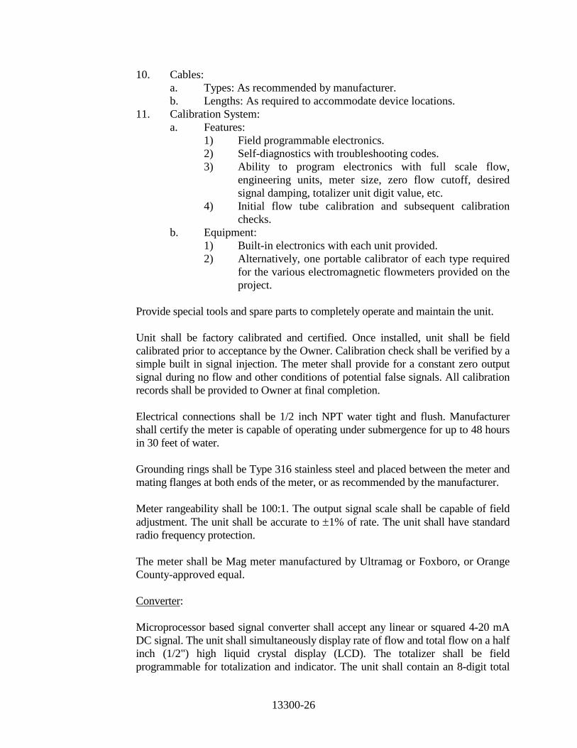
13300-26
10. Cables: a. Types: As recommended by manufacturer. b. Lengths: As required to accommodate device locations.
11. Calibration System: a. Features:
1) Field programmable electronics. 2) Self-diagnostics with troubleshooting codes. 3) Ability to program electronics with full scale flow,
engineering units, meter size, zero flow cutoff, desired signal damping, totalizer unit digit value, etc.
4) Initial flow tube calibration and subsequent calibration checks.
b. Equipment: 1) Built-in electronics with each unit provided. 2) Alternatively, one portable calibrator of each type required
for the various electromagnetic flowmeters provided on the project.
Provide special tools and spare parts to completely operate and maintain the unit.
Unit shall be factory calibrated and certified. Once installed, unit shall be field calibrated prior to acceptance by the Owner. Calibration check shall be verified by a simple built in signal injection. The meter shall provide for a constant zero output signal during no flow and other conditions of potential false signals. All calibration records shall be provided to Owner at final completion. Electrical connections shall be 1/2 inch NPT water tight and flush. Manufacturer shall certify the meter is capable of operating under submergence for up to 48 hours in 30 feet of water. Grounding rings shall be Type 316 stainless steel and placed between the meter and mating flanges at both ends of the meter, or as recommended by the manufacturer. Meter rangeability shall be 100:1. The output signal scale shall be capable of field adjustment. The unit shall be accurate to ±1% of rate. The unit shall have standard radio frequency protection. The meter shall be Mag meter manufactured by Ultramag or Foxboro, or Orange County-approved equal. Converter: Microprocessor based signal converter shall accept any linear or squared 4-20 mA DC signal. The unit shall simultaneously display rate of flow and total flow on a half inch (1/2") high liquid crystal display (LCD). The totalizer shall be field programmable for totalization and indicator. The unit shall contain an 8-digit total

13300-27
flow display and be provided with a battery back-up for total flow display, in the event of signal interruption or loss of signal. The total flow display, prior to signal interruption, shall not be lost or zeroed out. Power requirements shall be 120 VAC. The Indication Flow display shall be 3-digit, 1/2 inch high LCD. Converter shall be supplied with empty pipe detection feature. The accuracy of the Total Display shall be ±0.5 percent of rate over the full scale. The accuracy of the rate display shall be ±0.5 percent of rate over the full scale. The housing shall be a fire retardant glass-reinforced polyester plastic with provisions for surface mounting. The case shall be NEMA 4X rated suitable for outdoor installations. The window shall be tempered glass. Provide internal illumination for night reading.
Provide two output signals linear and directly proportional to flow as follows: 4-20mAdc isolated into 0-600 ohms. 0-10 kHz scaled pulse. Low Flow Cutoff Limit: Drive the output to zero when the measured flow rate is 1-10 percent (adjustable) of full scale and when fully developed flow no longer exists. High Impedance Sensing: Provide sensing amplifiers with high impedance to minimize effects of deposit build-up on the electrodes. Interchangeable Electronics: Provide converter/transmitter that is interchangeable with all flow meter sizes of manufacturer's same model.
The converter shall be manufactured by Ultramag, or Foxboro/Flexim, Siemens, or Orange County (Owner) Approved equal.
F2: FLOW ELEMENT AND TRANSMITTER, PROPELLER:
1. General: a. Function: Measure flow rate of a process liquid. b. Type: Flanged tube, propeller meter with magnetic coupled drive.
2. Service:
a. Fluid: Water. b. Pressure: 150 psi standard, 250 psi when noted. c. Temperature: 100 degrees F maximum. d. Flow Direction: Bi-directional measurement when noted.
3. Performance:
a. Accuracy: Plus or minus 2 percent of flow rate. 4. Element:
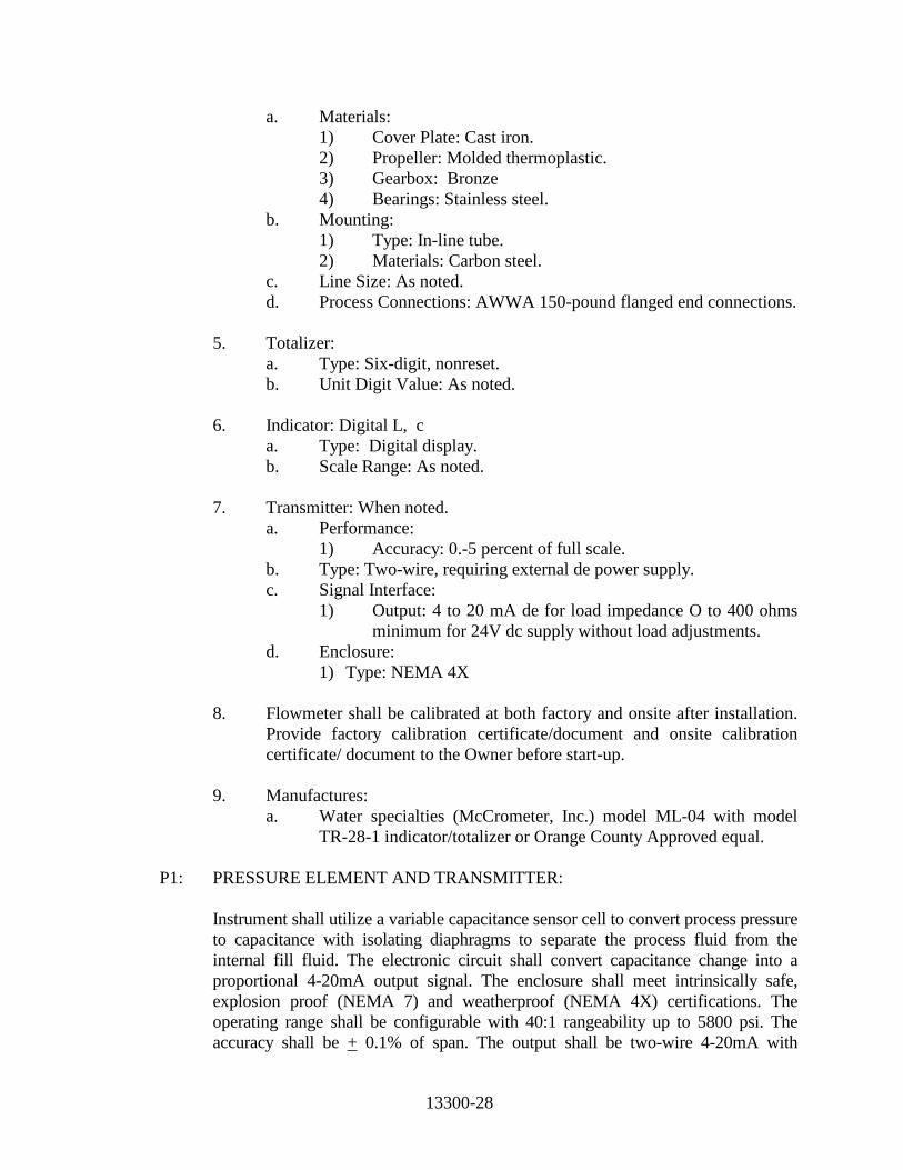
13300-28
a. Materials: 1) Cover Plate: Cast iron. 2) Propeller: Molded thermoplastic. 3) Gearbox: Bronze 4) Bearings: Stainless steel.
b. Mounting: 1) Type: In-line tube. 2) Materials: Carbon steel.
c. Line Size: As noted. d. Process Connections: AWWA 150-pound flanged end connections.
5. Totalizer: a. Type: Six-digit, nonreset. b. Unit Digit Value: As noted.
6. Indicator: Digital L, c
a. Type: Digital display. b. Scale Range: As noted.
7. Transmitter: When noted.
a. Performance: 1) Accuracy: 0.-5 percent of full scale.
b. Type: Two-wire, requiring external de power supply. c. Signal Interface:
1) Output: 4 to 20 mA de for load impedance O to 400 ohms minimum for 24V dc supply without load adjustments.
d. Enclosure: 1) Type: NEMA 4X
8. Flowmeter shall be calibrated at both factory and onsite after installation.
Provide factory calibration certificate/document and onsite calibration certificate/ document to the Owner before start-up.
9. Manufactures:
a. Water specialties (McCrometer, Inc.) model ML-04 with model TR-28-1 indicator/totalizer or Orange County Approved equal.
P1: PRESSURE ELEMENT AND TRANSMITTER:
Instrument shall utilize a variable capacitance sensor cell to convert process pressure to capacitance with isolating diaphragms to separate the process fluid from the internal fill fluid. The electronic circuit shall convert capacitance change into a proportional 4-20mA output signal. The enclosure shall meet intrinsically safe, explosion proof (NEMA 7) and weatherproof (NEMA 4X) certifications. The operating range shall be configurable with 40:1 rangeability up to 5800 psi. The accuracy shall be + 0.1% of span. The output shall be two-wire 4-20mA with

13300-29
superimposed digital communication using HART protocol. Unit shall operate on loop-power from 12 to 45 VDC. The unit shall have configurable 4 ½ digit numerical plus 5-character alphanumeric displays to indicate PV and output in Engineering Units. Configuration shall be performed using digital HART protocol with PC laptop software or using a HART hand-held configurator or through local adjustment. Provide configurator as part of package. Unit shall be Smar LD301 Series or approved equal.
P2: PRESSURE GAUGE As per specification 15130.
P3: PRESSURE SWITCH (DIAPHRAGM SENSOR) Pressure switch shall employ a diaphragm sensor and a Belleville disc spring for
setpoint stability and vibration resistance. Wetted parts are to be 316SS with BUNA-N "O" rings. Two setpoints shall be adjustable over selected range with an internal slotted adjustment with range scale. The enclosure shall be epoxy painted and meet the requirements of NEMA 4X. Pressure connection shall be ½" x 14 FMPT. Switch contact shall be 10A, 120VAC DPDT implying SPDT for each setpoint. Pressure switch shall be ITT NeoDyn Series 132P or Owner approved equal.
W1: DAY TANK SCALE As per specification 13219. Day tanks scales shall be Scaletron Industries Ltd., or equal. 2.09 LOOP DESCRIPTIONS A. See I-Drawings. 2.10 CONTROL STRATEGY SCHEDULES The control strategies are written descriptions of the programming required to implement
regulatory and sequential control of the unit processes. Control strategies shall fully reside in the memory of the designated PLC. Coefficients pertaining to control strategies shall be modifiable through the operator interface in the monitoring / control mode.
The I&C supplier shall include an additional 160 hours on-site to fine tune control systems and make minor software modifications in order to resolve any logic discrepancies encountered during start-up, and supply the Owner with a complete functional system. This shall be part of the bid package with no additional cost to the owner.

13300-30
A. Control Strategy: See Section 13610 for Control Strategy.
2.11 PROGRAMMING SOFTWARE The Contractor is responsible for using the PLC and SCADA programming software
Proworx NxT that the County is currently using for the PLC type specified under specification 13300. Contractor shall provide PLC software license and copy of software for this project to the Owner at completion of project. Contractor shall also provide a backup copy of software loaded onto PLC’s with initial settings pre-configured as noted during startup of project.
A. Programming software for Quantum Controllers shall be Schneider Unity.
B. Programming software for the Computer based SCADA/HMI system shall be GE
Proficy/iFix, version 5.8 or latest version currently used by owner. 2.12 TAGGING AND NUMBERING SYSTEMS
A. A tag convention consistent with Orange County Utility’s Water Division’s current standard shall be used in the HMI/SCADA database, HMI/SCADA graphics, and PLC programs. Contractor to coordinate with Orange County Utilities SCADA Administrator.
B. The tag convention shall use the facility code with a user defined abbreviated
process, unit identifier, and status for development of the tag name. The user defined abbreviations shall be consistent throughout all facilities.
C. The description field of the tag should be an English text description that clearly
describes the facility, process, instrument type/unit number, and status. For example, Tag Name: MR_FLU_P1_VENT-ST; this represents facility “Malcolm Road”, process “FLU”, pump “P1”, device “VENT”, and status “ST”. All tags developed for this project shall follow this tag convention.
2.13 NEW PLC RACKS AND I/O CARDS
A. Rack layouts consists of the following items:
MCP 16-Slot Rack 1 Layout (to be edited) Rack 0 Slot 0 Power Supply Rack 0 Slot 1 CPU with Modbus Plus Rack 0 Slot 2 NOE Module Rack 0 Slot 3 Digital Input Rack 0 Slot 4 Digital Input Rack 0 Slot 5 Digital Input Rack 0 Slot 6 Digital Input
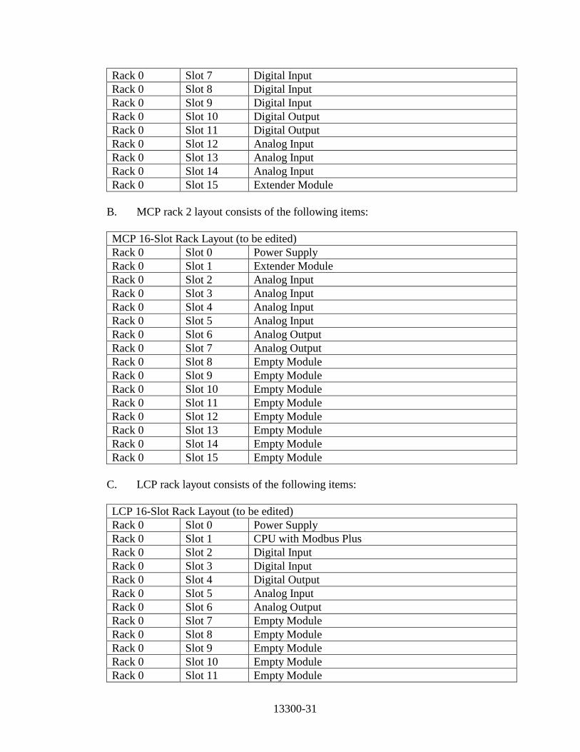
13300-31
Rack 0 Slot 7 Digital Input Rack 0 Slot 8 Digital Input Rack 0 Slot 9 Digital Input Rack 0 Slot 10 Digital Output Rack 0 Slot 11 Digital Output Rack 0 Slot 12 Analog Input Rack 0 Slot 13 Analog Input Rack 0 Slot 14 Analog Input Rack 0 Slot 15 Extender Module
B. MCP rack 2 layout consists of the following items:
MCP 16-Slot Rack Layout (to be edited) Rack 0 Slot 0 Power Supply Rack 0 Slot 1 Extender Module Rack 0 Slot 2 Analog Input Rack 0 Slot 3 Analog Input Rack 0 Slot 4 Analog Input Rack 0 Slot 5 Analog Input Rack 0 Slot 6 Analog Output Rack 0 Slot 7 Analog Output Rack 0 Slot 8 Empty Module Rack 0 Slot 9 Empty Module Rack 0 Slot 10 Empty Module Rack 0 Slot 11 Empty Module Rack 0 Slot 12 Empty Module Rack 0 Slot 13 Empty Module Rack 0 Slot 14 Empty Module Rack 0 Slot 15 Empty Module
C. LCP rack layout consists of the following items:
LCP 16-Slot Rack Layout (to be edited) Rack 0 Slot 0 Power Supply Rack 0 Slot 1 CPU with Modbus Plus Rack 0 Slot 2 Digital Input Rack 0 Slot 3 Digital Input Rack 0 Slot 4 Digital Output Rack 0 Slot 5 Analog Input Rack 0 Slot 6 Analog Output Rack 0 Slot 7 Empty Module Rack 0 Slot 8 Empty Module Rack 0 Slot 9 Empty Module Rack 0 Slot 10 Empty Module Rack 0 Slot 11 Empty Module
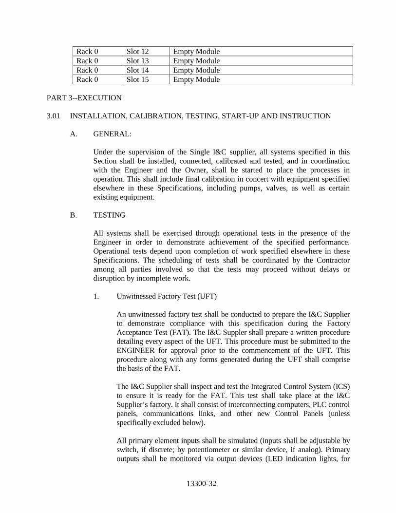
13300-32
Rack 0 Slot 12 Empty Module Rack 0 Slot 13 Empty Module Rack 0 Slot 14 Empty Module Rack 0 Slot 15 Empty Module
PART 3--EXECUTION 3.01 INSTALLATION, CALIBRATION, TESTING, START-UP AND INSTRUCTION A. GENERAL: Under the supervision of the Single I&C supplier, all systems specified in this
Section shall be installed, connected, calibrated and tested, and in coordination with the Engineer and the Owner, shall be started to place the processes in operation. This shall include final calibration in concert with equipment specified elsewhere in these Specifications, including pumps, valves, as well as certain existing equipment.
B. TESTING All systems shall be exercised through operational tests in the presence of the
Engineer in order to demonstrate achievement of the specified performance. Operational tests depend upon completion of work specified elsewhere in these Specifications. The scheduling of tests shall be coordinated by the Contractor among all parties involved so that the tests may proceed without delays or disruption by incomplete work.
1. Unwitnessed Factory Test (UFT) An unwitnessed factory test shall be conducted to prepare the I&C Supplier
to demonstrate compliance with this specification during the Factory Acceptance Test (FAT). The I&C Suppler shall prepare a written procedure detailing every aspect of the UFT. This procedure must be submitted to the ENGINEER for approval prior to the commencement of the UFT. This procedure along with any forms generated during the UFT shall comprise the basis of the FAT.
The I&C Supplier shall inspect and test the Integrated Control System (ICS)
to ensure it is ready for the FAT. This test shall take place at the I&C Supplier’s factory. It shall consist of interconnecting computers, PLC control panels, communications links, and other new Control Panels (unless specifically excluded below).
All primary element inputs shall be simulated (inputs shall be adjustable by
switch, if discrete; by potentiometer or similar device, if analog). Primary outputs shall be monitored via output devices (LED indication lights, for

13300-33
discrete; a meter, digital display (12-bit min. resolution) or other such analog device, if analog output).
During the UFT, the Contractor shall test the communications links and
demonstrate error-free communications to and from each node on the fiber optic network. Verify that each I/O point is consistently mapped at the computer node, at the PLC I/O card, in the PLC memory, and at the I/O simulated device according to the database provided by the software engineer. Verify the proper operation of each of the pilot devices on each of the control panels, if any.
Excluded New Panels: None 2. Factory Acceptance Test (FAT):
The I&C Supplier shall test the entire control system. The test shall take place at the I&C Supplier’s factory. The I&C Supplier shall simulate all inputs and outputs as performed in the UFT. The software engineer shall load application programs into each PLC. The software engineer shall load the HMI application into the computer. The I&C Supplier shall provide travel and accommodations for Owner and Owner’s Consultant to witness the FAT. Provide a minimum of 2 weeks’ notice to the Owner/Engineer before conducting testing. Prior to commencement of the FAT, the I&C Supplier shall furnish the following documentation to the ENGINEER:
a. All Drawings, Specifications, Addenda, and Change Orders
b. Master copy of the written FAT procedures c. List of equipment to be tested d. Shop drawings of equipment to be tested e. Preliminary Software documentation submittal
Daily Schedule for FAT:
a. Begin each day with a meeting to review the day’s test schedule
b. End each day with a meeting to review the day’s test results and to review and to revise the next day’s test schedule, if required.
The I&C Supplier shall repeat the I/O point mapping consistency check as before, with the addition of verification of mapping on HMI screens. Those variables, which are not I/O but are variables which exist in the PLC and HMI software only (see preliminary software documentation), shall all be checked.

13300-34
Check the function of each loop, including set points, alarms, displays, and operator interface. Check one loop of each type and 20% (min.) of all loops. Check data logging, alarm logging, and event logging. Test all non-loop-specific functions including, but not limited to the following:
a. Demonstrate capacity of system for expansion. Include tests for both storage capacity and processing capacity.
b. Include tests for timing requirements. c. Demonstrate online and offline diagnostic tests, procedures
and displays. d. Demonstrate Failure Mode and Backup Procedures: Power
failure, auto restart, disk backup and reload, retentive outputs.
Correct deficiencies found and complete correction of deficiencies prior to
shipment to site. Failed Tests shall be repeated and witnessed by the OWNER and
ENGINEER. With approval of the ENGINEER or OWNER certain tests may be conducted by the I&C Supplier and Witnessed by the OWNER and ENGINEER during START-UP.
See section 3.03 supplements for sample "Loop Status Report" and
"Functional Acceptance Test Sheet". C. INSTALLATION AND CONNECTION: 1. The Contractor shall install and connect all field-mounted components and
assemblies under the criteria imposed in Part 1, 1.03, herein. The installation personnel shall be provided with a final reviewed copy of the Shop Drawings and data.
2. The instrument process sensing lines and air signal tubing shall, in general,
be installed in a similar manner to the installation of conduit specified under Section 16050. Individual tubes shall be run parallel and near the surfaces from which they are supported.
Supports shall be used at intervals of not more than 3 feet of rigid tubing. Bends shall be formed with the proper tool and to uniform radii and shall
be made without deforming or thinning the walls of the tubing. Plastic clips shall be used to hold individual plastic tubes parallel. Ends of tubing shall be square cut and cleaned before being inserted in the fittings. Bulkhead fittings shall be provided at all panels.

13300-35
3. The Contractor shall have a technical field representative of the I&C
supplier to instruct these installation personnel on any and all installation requirements; thereafter, the technical field representative shall be readily available by telephone to answer questions and supply clarification when needed by the installation personnel.
Where primary elements (supplied by I&C supplier) shall be part of a
mechanical system, the I&C supplier shall coordinate the installation of the primary elements with the mechanical system manufacturer.
4. Fiber optic cable shall be furnished by the I&C Supplier and installed by
the Corning or equal certified I&C provider with a 25 year warranty guarantee. The I&C Supplier shall provide the services of an experienced fiber optic cable terminator and tester. The I&C Supplier shall supervise the cable installation and shall carry out all terminations at the I/O racks, repeaters, and data concentrators at PLC’s and computers. Fiber optic cable termination shall be carried out using the appropriate connectors and termination kit. All fiber optic system components shall be products of one manufacturer.
Fiber optic cable system shall be designed to minimize cable splicing. Where splicing becomes necessary perform fusion splice with loss not to exceed 0.2 dB. Test all splices with an Optical Time Domain Reflectometer (ODTR) bi-directionally to verify splice loss at the time of splicing. Redo any splices not conforming to Specifications. Provide means to protect the unspliced portions of the cable from intrusion of moisture and other foreign matter. Identify required splices in the submittal. Splices not identified in the submittal shall not be acceptable unless approved by the ENGINEER. After the fiber optic data link is in place, test the attenuation from hub to hub bi-directionally and document test results. Provide a complete fiber optic report showing all losses from newly installed and modified runs. Attenuation in excess of 3.5 dB/km at 850 nm wavelength or 1.0 dB/km at 1300 nm wavelength shall require the I&C supplier to replace the defective sections and retest until the attenuation is below the attenuation allowed per kilometer at the wavelengths cited. The I&C Supplier is responsible for the satisfactory performance of all fiber optic data links. Demonstrate and document error free bi-directional data files transfer from each host computer to each PLC node.
5. Finally, after all installation and connection work has been completed, the
technical field representative shall check it all for correctness, verifying polarity of electric power and signal connections, making sure all process
13300-36
connections are free of leaks, and all such similar details. If the initial inspection finds no deficiencies, the technical field representative shall proceed to the certification to the Contractor. Any completed work that is found to have deficiencies shall have those deficiencies corrected by installation personnel at no additional cost to the Owner. The technical field representative shall then recheck the work after the identified deficiencies are corrected. If the technical field representative finds deficiencies in the follow-up inspection, then remedial action shall be taken by the Contractor at no cost to the Owner. This pattern shall be repeated until the installation is free from defect. The technical field representative shall then certify in writing to the Contractor that for each loop or system that he has inspected is complete and without discrepancies.
6. The field representative of the Single I&C supplier shall coordinate all
work required to interface the new equipment and control devices with the existing equipment, including all required modifications to existing equipment and related devices.
D. CALIBRATION 1. All instruments and systems shall be calibrated after installation, in
conformance with the component manufacturer's written instructions. This shall provide that those components having adjustable features are set carefully for the specific conditions and applications of this installation, and that the components and/or systems are within the specified limits of accuracy. Defective elements which cannot achieve proper calibration or accuracy, either individually or within a system, shall be replaced. This calibration work shall be accomplished by the technical field representatives of the I&C system supplier who shall certify in writing to the Contractor that for each loop or system all calibrations have been made and that all instruments are ready to operate. See section 3.03 supplements for sample "Instrumentation Calibration Sheet".
2. Proof of Conformance - The burden of proof of conformance to specified
accuracy and performance is on the Contractor using its designated Single I&C supplier. The Contractor shall provide Flow Meter Certifications (Including Factory Certifications) to Owner prior to pumping water. The Contractor's designer shall supply necessary test equipment and technical personnel if called upon to prove accuracy and/or performance, at no separate additional cost to the Owner, wherever reasonable doubt or evidence of malfunction or poor performance may appear within the guarantee period.

13300-37
E. PRE-COMMISSIONING
The I&C Supplier shall test each loop (discrete and analog) to determine if it is functioning correctly. The I&C Supplier shall furnish a loop sheet for each loop to be tested. The loop sheet shall represent the actual “as-built” condition of the loop. The I&C Supplier shall perform a field functional loop test which shall be witnessed by the ENGINEER and OWNER. If the loop fails the functional test, the I&C Supplier shall coordinate repairs for the CONTRACTOR to correct whatever is wrong with the loop at no additional cost to the OWNER. The I&C Supplier shall retest the loop until it is approved. Each loop shall be tested and approved by ENGINEER and OWNER until all loops have been approved.
F. START-UP AND INSTRUCTION When all systems are assessed by the Contractor to have been successfully carried
through complete operational tests with a minimum of simulation, and the Engineer concurs in this assessment, plant start-up by the Owner's operating personnel can follow. For a minimum of three times for (4) hours prior to start-up, operating and maintenance personnel shall be instructed in the functions and operation of each system and shall be shown the various adjustable and set point features which may require readjustment, resetting or checking, re-calibration or maintenance by them from time to time. This instruction shall be scheduled at a time arranged with the Owner at least two (2) weeks in advance. Instruction shall be given by qualified persons who have been made familiar in advance with the systems. All equipment shall be checked during the first year of operation at intervals of three months for a period of not less than one day or as may be required to correct any defects to the satisfaction of the Owner.
G. PLANT SHUTDOWNS The Single I&C supplier shall carefully examine all work to be performed relative
to the installation of new equipment and control devices. Work shall be scheduled to minimize required plant shutdown times. Plant shutdown times shall be scheduled with Owner with a minimum of 2 weeks’ notice given to the Owner.
I. COORDINATION WITH OTHER CONCURRENT PROJECTS The single I&C supplier shall coordinate extensively with other I&C suppliers of
concurrent projects.

13300-38
3.02 TRAINING
A. General:
1. Provide an integrated training program to meet specific needs of Owner’s personnel. Provide outlined training schedule to Owner for review outlining training course material for approval by Owner prior to training program.
2. Field Instruments - Provide instruction on (2) 8-hour working shifts to accommodate the Owner’s personnel schedule.
3. Control Panel Hardware - Provide instruction on (2) 8-hour working shifts
to accommodate the Owner’s personnel schedule. 4.
5. Owner reserves the right to make and reuse video tapes of training
sessions if applicable.
6. Training to include software calibration, system tuning, and system updates.
B. Operations and Maintenance Training:
1. Include a review of O&M manuals, expendables, and test equipments.
2. Training session duration shall be minimum 8 hours. Provide training
schedule with outlines at least one week before the training to the Owner.
3. Training shall include a minimum understanding of loop functions, loop operation, component calibration, adjustments such as controller tuning, switch trip point, etc., and periodic maintenance.
C. Hirschmann (or equal) Ethernet Switch Onsite Training:
1. In additional to the factory level training, provide an onsite training for the
Hirschmann Ethernet switch models that are installed as part of this project. The training shall be by a system integrator (either from Hirschmann or ceritified by Hirschmann) and shall include a minimum of switch configuration, troubleshooting, connection, etc. as recommended by the manufacturer. Provide instruction on (2) 8-hour working shifts to accommodate the Owner’s personnel schedule.

13300-39
3.03 SUPPLEMENTS A. Supplements listed below, following "END OF SECTION" are part of this
Specification. 1. Instrumentation Calibration Sheet 2. Loop Status Report 3. Functional Acceptance Test Sheet 3.04 WARRANTY
A. Submit in accordance with requirements of Section 01740, warranties covering the items included under this Section. Unit shall be provided with a full factory warranty of 5 years from date of ENGINEER's acceptance.
B. Provide (in bid) a platinum maintenance agreement from manufacturer of supplied equipment for 5 years including all required maintenance, calibration and warrantee needs. Maintenance agreement to include 24 hour response time from time of service call.
C. Maintenance Agreement to be included in suppliers Bid.
END OF SECTION


13300-40
LOOP STATUS REPORT PROJECT NAME:_______________ PROJECT NO.:_______________
FUNCTIONAL REQUIREMENTS
COMPONENT STATUS
TAG NO.
DELIVERED*
TAG/IDENTIFI-
CATION CHECK*
INSTALLATION CHECK
TERMINATION
WIRING*
TERMINATION
TUBING*
CALIBRATED*
REMARKS
LOOP READY FOR START-UP
BY
DATE
* INITIAL AND DATE WHEN COMPLETE

13300-41
FUNCTIONAL ACCEPTANCE TEST SHEET PROJECT NAME: ________________________ PROJECT NO. :
FUNCTIONAL REQUIREMENTS AND SUMMARY OF COMPONENTS: (ATTACH XEROX OF LOOP SPECIFICATION FROM THE CONTRACT DOCUMENTS)
VERIFICATION OF LOOP STATUS REPORT AND BY:_____________________________ INSTRUMENT AND VALVE CALIBRATION SHEETS DATE:_____________________________ DEMONSTRATION TEST(S): FOR EACH FUNCTIONAL REQUIREMENT OF THE LOOP: REQUIRED PERFORMANCE (a) LIST AND NUMBER THE REQUIREMENT (c) CITE THE RESULTS THAT WILL VERIFY THE (b) BRIEFLY DESCRIBE THE DEMONSTRATION (d) PROVIDE SPACES FOR INITIAL AND DATE OF TEST TEST WITNESS.
PERFORMED BY:
LOOP ACCEPTED BY (OWNER)
WITNESSED BY:
BY
COMPLETED DATE:
DATE
CHECK IF REMARKS ON REVERSE SIDE LOOP NO.

13300-42
INSTRUMENTATION CALIBRATION SHEET
COMPONENT CODE: NAME:
MANUFACTURER: MODEL: SERIAL:
PROJECT NUMBER: NAME:
RANGE VALUE UNITS INDIATE/ CHART ______ _______ RECORD SCALE ______ _______ TRANS/ INPUT ______ _______ CONVERT OUTPUT ______ _______
COMPUTE FUNCTIONS
CONTROL ACTION (DIRECT/REVERSE) MODES (P/I/D) SWITCH UNIT RANGE (VALUE/UNITS) DIFFERENTIAL (FIXED/ADJUSTABLE) RESET (AUTOMATIC/MANUAL)
ANALOG DISCRETE
REQUIRED
AS CALIBRATED
REQUIRED
AS CALIBRATED
REMARKS
IN
SCALE
OUT
SCALE
OUT
SCALE
OUT
NUMBER
TRIP PT
RESET PT
TRIP PT
RESET PT
CODE
C. MODE SETTINGS: P I D
COMPONENT CALIBRATED AND READY FOR START-UP
BY DATE
TAG NO.


13400-1
SECTION 13400
DIGITAL VIDEO SECURITY SYSTEM PART 1 -- GENERAL
1.01 THE REQUIREMENT
A. The Contractor shall provide all digital video security cameras, network cables, video storage and management servers, software, and all required equipment, accessories, programming and appurtenances as herein specified and as shown on the Drawings.
1.02 RELATED WORK SPECIFIED ELSEWHERE
A. Section 13300 – Instrumentation and Controls
B. Section 13165 - Process Instrumentation and Controls – Products.
1.03 GENERAL INFORMATION AND DESCRIPTION
A. These Specifications are intended to give a general description of what is required,
but do not cover all details which will vary in accordance with the requirements of the equipment furnished. They are, however, intended to cover the furnishing, the shop testing, the delivery and complete installation and field testing, of all materials, equipment and appurtenances for complete systems herein specified, whether specifically mentioned in the Specification or not.
1.04 SUBMITTALS
A. General: The Contractor shall submit shop drawings and Operation and
Maintenance instructions and other information as specified in accordance with Section 01340 – Shop Drawings, Working Drawings, and Samples and Section 13300 – Instrumentation and Controls.
1.05 MANUFACTURER'S SERVICE REPRESENTATIVE
A. The Contractor shall provide the services of a qualified security system subcontractor or manufacturer’s representative who shall adequately supervise the installation and testing of all equipment furnished under this Contract and instruct

13400-2
the Contractor's personnel and the Owner's personnel in its maintenance and operation.
B. Any additional time required to achieve successful installation and operation shall
be at the expense of the Contractor.
1.06 PRODUCT DELIVERY STORAGE AND HANDLING
A. All new equipment shall be properly protected in accordance with manufacturer requirements so that no damage or deterioration will occur during a prolonged delay from the time of shipment until installation is complete and the system is ready for operation.
1.07 MANUFACTURER'S EXPERIENCE A. The video security system provided under this Contract shall be furnished by the
instrumentation and control system subcontractor.
PART 2 -- PRODUCTS AND REQUIREMENTS
2.01 INDOOR DIGITAL SECURITY CAMERAS
A. Indoor digital security cameras shall be progressive scan type cameras capable of
providing full frame rate video in resolutions up to 1 megapixel including HDTV 720p. The cameras shall be fully compatible with the server-based video management software specified herein. Cameras shall support motion detection configurable to detect motion in the entire video frame or limited to specific regions of the frame. The cameras shall have the following features:
1. Resolution: 1280x800 to 160x90 2. Frame Rate: 25/30 fps in all resolutions @ 50/60 Hz power 3. Compression: H.264 (MPEG-4 Part 10/AVC), Motion JPEG 4. Communication port: RJ45 10BASE-T/100BASE-TX 5. Alarm Contacts: 1 alarm input and 1 output 6. Lens: 2.8 mm, Horizontal field of view: 84°, F2.0 7. Power Supply: Power over Ethernet (PoE) 8. Casing: Aluminium and polycarbonate
B. Indoor digital security cameras shall be model M1054 Network Camera by Axis. 2.02 OUTDOOR DIGITAL SECURITY CAMERAS A. Outdoor digital security cameras shall be the rugged outdoor type utilizing infrared
LED technology with automatically removable infrared filter for day and night use.
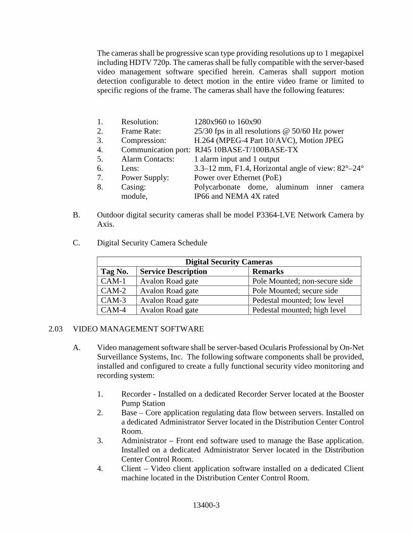
13400-3
The cameras shall be progressive scan type providing resolutions up to 1 megapixel including HDTV 720p. The cameras shall be fully compatible with the server-based video management software specified herein. Cameras shall support motion detection configurable to detect motion in the entire video frame or limited to specific regions of the frame. The cameras shall have the following features:
1. Resolution: 1280x960 to 160x90 2. Frame Rate: 25/30 fps in all resolutions @ 50/60 Hz power 3. Compression: H.264 (MPEG-4 Part 10/AVC), Motion JPEG 4. Communication port: RJ45 10BASE-T/100BASE-TX 5. Alarm Contacts: 1 alarm input and 1 output 6. Lens: 3.3–12 mm, F1.4, Horizontal angle of view: 82°–24° 7. Power Supply: Power over Ethernet (PoE) 8. Casing: Polycarbonate dome, aluminum inner camera
module, IP66 and NEMA 4X rated B. Outdoor digital security cameras shall be model P3364-LVE Network Camera by
Axis. C. Digital Security Camera Schedule
Digital Security Cameras Tag No. Service Description Remarks CAM-1 Avalon Road gate Pole Mounted; non-secure side CAM-2 Avalon Road gate Pole Mounted; secure side CAM-3 Avalon Road gate Pedestal mounted; low level CAM-4 Avalon Road gate Pedestal mounted; high level
2.03 VIDEO MANAGEMENT SOFTWARE
A. Video management software shall be server-based Ocularis Professional by On-Net
Surveillance Systems, Inc. The following software components shall be provided, installed and configured to create a fully functional security video monitoring and recording system:
1. Recorder - Installed on a dedicated Recorder Server located at the Booster
Pump Station 2. Base – Core application regulating data flow between servers. Installed on
a dedicated Administrator Server located in the Distribution Center Control Room.
3. Administrator – Front end software used to manage the Base application. Installed on a dedicated Administrator Server located in the Distribution Center Control Room.
4. Client – Video client application software installed on a dedicated Client machine located in the Distribution Center Control Room.

13400-4
2.04 VIDEO MANAGEMENT HARDWARE
A. The equipment shall be designed to operate in an indoor environment. The
equipment shall be capable of operation in an ambient temperature range of 0 to 40 degrees C and a relative humidity of 0-90%, non-condensing. The equipment shall be capable of operation on supply voltages of 102-132 VAC at 47-63 Hz. Video management hardware shall be as described below.
B. All video management hardware and associated peripherals shall be approved for
use with the video management software specified above. C. Recorder Server 1. Rack-mounted computer system as manufactured by Gateway 2000,
Compaq, Dell, Hewlett Packard, IBM or equal with the following features: a. CPU: Intel Core i7-4930K @ 3.40GHz or Intel Xeon E5-2640 v3
@ 2.60GHz or better b. RAM: 16 GB or better c. HDD: Minimum 800 GB free disk space @ 7200 RPM d. Network: Ethernet with 1000 MBit/s e. Operating System: Microsoft Windows Server 2012 R2, 64-bit 2. Three-button mouse with roller button by Logitech, Microsoft, or equal. 3. Standard PC keyboard. 4. Flat-screen color monitor as manufactured by Mitsubishi, NEC, ViewSonic,
or equal, with the following minimum features: a. 24" LED-backlit flat screen b. 1920 x 1080 resolution c. 0.28 mm dot pitch d. Multi-scanning 31.5-81.1 KHz horizontal and 56-76Hz vertical e. DisplayPort, DVI-D and VGA inputs f. Height-adjust, pivot, tilt and swivel

13400-5
D. Administrator Server
1. Rack-mounted computer system as manufactured by Gateway 2000, Compaq, Dell, Hewlett Packard, IBM or equal with the following features:
a. CPU: Intel Core i3 or better
b. RAM: 8 GB or better c. HDD: Minimum 500 GB d. Operating System: Microsoft Windows, coordinate with vendor for
compatible versions at time of purchase e. Additional software: Microsoft .NET 4.5 Framework; IIS 6.0 or
newer 2. Three-button mouse with roller button by Logitech, Microsoft, or equal. 3. Standard PC keyboard. 4. Flat-screen color monitor as manufactured by Mitsubishi, NEC, ViewSonic,
or equal, with the following minimum features: a. 24" LED-backlit flat screen b. 1920 x 1080 resolution c. 0.28 mm dot pitch d. Multi-scanning 31.5-81.1 KHz horizontal and 56-76Hz vertical e. DisplayPort, DVI-D and VGA inputs f. Height-adjust, pivot, tilt and swivel E. Client 1. Rack-mounted computer system as manufactured by Gateway 2000,
Compaq, Dell, Hewlett Packard, IBM or equal with the following features: a. CPU: Intel Core i7 or better b. RAM: 16 GB or better

13400-6
c. Operating System: Microsoft Windows, coordinate with vendor for compatible versions at time of purchase
d. Graphics Adapter: PCI-Express, 256 MB RAM, Direct 3D
supported 2. Three-button mouse with roller button by Logitech, Microsoft, or equal. 3. Standard PC keyboard. 4. Flat-screen, Ultra HD, color monitor as manufactured by Mitsubishi, NEC,
ViewSonic, or equal, with the following minimum features: a. 28" LED-backlit flat screen b. 3840 x 2160 resolution c. 0.17 mm dot pitch d. Multi-scanning 24-160 KHz horizontal and 24-75 Hz vertical e. DisplayPort, HDMI, DVI, USB f. Height-adjust, pivot, tilt and swivel F. Uninterruptible Power Systems 1. Uninterruptible power systems (UPS) shall be furnished for all Video
Management hardware in accordance with Section 13165 Process Instrumentation and Controls – Products.
2. One UPS shall be provided and installed for the Recorder Server and all appurtenances.
3. One UPS shall be provided and installed for the Administrator Server and Client.
G. Network 1. Network interfaces shall be furnished in accordance with Section 13413 of
the Specifications. 2. All video data shall be segmented to maintain layer two VLAN separation
from PLC data on the network.

13400-7
PART 3 -- EXECUTION 3.01 REQUIREMENTS A. Refer to Section 13300 Instrumentation and Controls.
END OF SECTION

13413-1
SECTION 13413
OPTICAL FIBER CABLING SYSTEMS PART 1 - GENERAL
1.01 SUMMARY
A. Section Includes: Product and installation requirements for the following:
1. Fiber-optic (FO) Cables.
2. Fiber-optic Connectors, Couplers, and Patch Panels.
1.02 SUBMITTALS
A. Shop Drawings: Submit in accordance with Section 01340, Shop Drawings covering the items included under this Section. Shop Drawing submittals shall include:
1. Product data for each type of product specified.
2. Product certificates, signed by the communication system manufacturers, certifying that the cables are suitable for the connected equipment as described in "Quality Assurance" Article below.
B. Contract Closeout: Submit in accordance with Section 01700.
1.03 QUALITY ASSURANCE
A. Manufacturers Qualifications: Firms regularly engaged in manufacture of equipment, of types and sizes required, and whose products have been in satisfactory use in similar service for not less than 5 years.
B. Connected Equipment Manufacturer Certifications: Where cables specified in this
Section are used to provide signal paths for systems specified in other sections of these Specifications, or for systems furnished under other contracts, obtain review of the cable characteristics and certification for use with the connected system equipment by the connected equipment manufacturers.
C. UL Compliance: For cables that may be run in plenum ceilings or other air-handling
spaces, provide cables tested for compliance with applicable requirements of UL Standard 910, "Test Method for Fire and Smoke Characteristics of Electrical and Optical Fiber Cables Used in Air-Handling Spaces." In addition, provide FO cables that have passed the UL VW-1 flame test.

13413-2
D. EIA/TIA Compliance: Comply with applicable requirements of EIA Standards, EIA-440, -455, -458, -475, -509, –568-b.3, and 598-a pertaining to optical fiber cable and system component construction and installation. EIA/TIA-455-61, FOTP-61, Measurement of Fiber or Cable Attenuation Using an OTDR.
E. Fiber Optics Experience: Contractor must be able to prove to the satisfaction of Owner
that it has significant experience in the installation of fiber-optics cable systems. Installation must include installation of fiber-optics cable, fiber termination, knowledge of interconnect equipment, and a thorough knowledge of testing procedures.
F. Labeling: Handwritten labels are not acceptable. All labels shall be machine printed on
clear or opaque tape, stenciled onto adhesive labels, or type written onto adhesive labels. The font shall be at least 1/8 inch in height, block characters, and legible. The text shall be of a color contrasting with the label such that is may be easily read. If labeling tape is utilized, the font color shall contrast with the background. Patch panels shall exhibit workstation numbers or some type of location identifier, in sequential order, for all workstations or devices attached. Each fiber-optics cable segment shall be labeled at each end with its respective identifier.
G. Fiber-Optics Interconnect Equipment (Patch Panels): Interconnect equipment shall be
used in all fiber cable installations. Patch panels shall be mounted in the equipment racks or panel mounted. Interconnect equipment mounted in racks shall be affixed to the rack by at least 4 screws. All fiber-optics interconnect devices shall be assembled and installed in accordance with the manufacturer’s instructions and recommendations.
H. Patch Cords: Patch cords shall be provided for each fiber-optic port on the patch panel.
Patch cords shall meet or exceed technical specifications of all installed fiber-optic cable. Patch cord connectors shall be matched with patch panel connector type and network fiber module connector type as required.
1.04 COMMISSIONING
A. Subsequent to hook-ups of FO system to signal sources and destination equipment, operate systems to demonstrate proper functioning. Replace malfunctioning FO cabling system items with new materials, and then retest until satisfactory performance is achieved.

13413-3
PART 2 - PRODUCTS
2.01 MANUFACTURERS
A. Subject to compliance with specified requirements, manufacturers offering products which may be incorporated in Work include:
1. FO Cables:
a. Corning Infinicor SX+ Optical Fiber, or Equal, for multi-mode applications. b. Corning NexCor Optical Fiber, or Equal, for single-mode applications.
2. FO Connectors and Couplers:
a. AMP Netcon. b. AT&T Network Systems. c. Corning. d. Honeywell, Inc. e. ITT Corp. f. Thomas and Betts Corp.
3. FO Patch Panels:
a. Panduit. b. Volition.
2.02 OPTICAL FIBER CABLING SYSTEMS
A. Fabricate system using manufacturer's standard materials as indicated by published product information and in sizes, types, and performance characteristics as indicated.
B. FO Cables: Factory fabricated, single channel, low loss glass type, fiber-optic
multimode graded-index cables with the following operational and construction features:
1. Multi-mode Fibers:
a. Cable Type shall be Corning FREEDM One Indoor/Outdoor Tight-Buffered Cable.
b. Number of Fibers: 6 minimum or as listed on Drawings.
c. Core Diameter: 50 microns or as listed on Drawings.
d. Cladding Diameter: 125 microns or as listed on Drawings.
e. Subunit Size: 2.0 mm or as listed on Drawings.

13413-4
f. Maximum Attenuation: Less than 2.5 dB/850 nm.
g. Minimum Bandwidth: Greater than 500 MHz-km.
h. Minimum Bend Radius (Unloaded): 10 cm (3.1 in).
i. Operating Temperature Range: -20 to +70 degrees C.
C. FO Connectors: Stainless steel, fiber-optic cable connectors, capable of terminating FO glass cables with diameters from 8 through 1,000 microns. Fabricate connectors with optical fiber, self-centering, axial alignment mechanisms. Provide ST style connectors as required or shown on Drawings.
2.03 SPARE PARTS
A. Provide at end of project the following spare parts:
1. Provide twenty (20) Optical Fiber splice pigtails.
2. One (1) optical fiber splice kit including optical fiber tester. PART 3 - EXECUTION
3.01 EXAMINATION
A. Examine areas and conditions with the Installer present for compliance with
requirements, and other conditions affecting the performance of optical fiber cabling system. Do not proceed with Work until unsatisfactory conditions have been corrected in a manner acceptable to Installer.
3.02 INSTALLATION
A. Install fiber-optic cables and associated equipment and devices in accordance with
industry standards and manufacturer's written instructions.
B. Install fiber-optic cable without damage to fibers, cladding, or jacket. Ensure that media manufacturer's recommended pulling tensions are not exceeded. Do not, at any time, bend cables to smaller radii than minimums recommended by manufacturer.
C. Install FO cables simultaneously where more than one cable is being installed in same
raceway. Use pulling lubricant where necessary; compound used must not deteriorate cable materials. Do not use soap. Use a pulling means, including fish tape, rope, and basket-weave grips, that will not damage media or raceway.
D. No splices are allowed, except at indicated splice points.

13413-5
3.03 GROUNDING
A. Provide grounding connections for FO cable and other system components as required
by manufacturer's written instructions.
3.04 APPLICATIONS
A. Install optical fiber cabling for project applications as detailed on drawings.
3.05 FIELD QUALITY CONTROL
A. Testing: Testing shall be done by Contractor with at least 5 years of experience in testing fiber-optic cabling systems. Contractor shall test each fiber strand. Owner reserves the right to have representation present during all or a portion of the testing process. Contractor must notify Owner 5 days prior to commencement of testing. If Owner elects to be present during testing, test results will only be acceptable when conducted in the presence of Owner. Any fiber-optic cable left non-terminated at the discretion of Owner, shall be tested using an adequate light source to determine that all installed strands are not damaged.
B. Fiber-Optics Cable: Each fiber strand shall undergo bi-directional testing for signal
attenuation losses using power meter and light source. Testing shall also include Optical Time Domain Reflectometer (OTDR) at both 850 and 1,300 nanometers for all installed fiber strands.
1. Recommended Test Equipment:
a. Multimode: Siecor OM-100F and OS-100D or equivalent power meter and light source.
b. Multimode: Siecor OTDRPlus with appropriate modules for testing.
2. Tests:
a. Multi-mode: Bi-directional signal attenuation at 850 and 1,300 nm.
3. Test Criteria: Signal loss of less than 10 dB through entire fiber path, including cable, couplers and jumpers.
C. Documentation (Fiber Optic): Contractor shall provide documentation to include test
results and as-built Drawings. Fiber Test Results: The results of the fiber testing shall be entered into the form "Fiber Attenuation Tests Results." Handwritten results are acceptable provided the test is neat and legible. Copies of test results are not acceptable. Only original signed copies will be acceptable.

13413-6
1. Each cable installed shall undergo complete testing in accordance with TIA/EIA TSB-67 to guarantee performance to this standard.
2. All required documentation shall be submitted within 30 days at conclusion of the project to Owner.
3. Test Criteria: Pass rate to conform to latest TIA/EIA Standards that incorporate link performance testing through entire path, including cable, couplers, and jumpers.
D. Acceptance: Acceptance of the Data Communications System, by Owner, shall be
based on the results of testing, functionality, and the receipt of documentation.
3.06 CLEANING
A. Clean optical fiber cabling and components of dirt and construction debris upon completion of installation.
3.07 WARRANTY
A. Fiber Optic cable and splices shall be provided with a 20 year full warranty covering
material and labor.
END OF SECTION
13610-1
SECTION 13610
DATA ACQUISITION AND PROCESS CONTROL SYSTEM PART 1 - GENERAL 1.01 DESCRIPTION A. Scope of Work: 1. The Primary Instrumentation and Control System Supplier (System
Supplier) shall furnish all labor, materials, modifications, programming, services and incidentals required to install and place into operation a digital computer-based data acquisition and process control system (DACS) in a distributed network configuration as specified and shown on the Contract Drawings, Section 13300: Instrumentation and Controls.
2. The System Supplier shall supply all equipment, materials, programming,
and services, hereinafter termed the system. The System Supplier shall provide all equipment, materials, programming, software with licensed backup, modifications and interfacing to existing equipment, calibrations and services that are required to successfully interface and interconnect any other control systems and associated equipment that are specified or designated in any drawings or specification provisions in Division 11: Equipment, Division 13: Special Construction, Division 15: Mechanical, and Division 16: Electrical of these Specifications for the purpose of providing a fully integrated and functional control system as specified herein. Successful integration and interconnection of the data acquisition and process control system to any of the areas of interface specified shall require the System Supplier to provide the necessary data highways and I/O capability.
3. The System Supplier shall be responsible for providing accessory devices,
including furnishing and installation of control switches and signal converters and changes to software necessary to perform the intent as shown in P&IDs and as specified in the functional process descriptions, providing services to calibrate all analog transmitters which provide inputs to the system, and services necessary to achieve a fully integrated and operational system as shown on the Contract Drawings, Section 13615 and described hereinafter.
4. The System Supplier shall furnish for installation by the Contractor all
cabling and cable accessories, including tools necessary for connecting the control system peripherals.
13610-2
5. The System Supplier shall furnish startup assistance and operator and
maintenance training necessary for successful operation and maintenance of the integrated control system.
6. Provide GE Proficy workstations with the latest version of iHistorian 7. Modify all local HMIs to reflect the proposed graphics and control system
configurations. 8. Provide the fiber optic loop topography as shown in the Contract
Drawings. B. Related Work Described Elsewhere:
1. Instrumentation and Controls: Section 13300.
2. Instrumentation and Controls – Training: Section 13300.
3. Process Instrumentation and Control – Products: Section 13615
4. Electrical: Division 16.
1.02 QUALITY ASSURANCE:
A. Qualification requirements are specified under Section 13300: Instrumentation and Controls.
1.03 SUBMITTALS:
A. Refer to Section 01340 Shop Drawings, Working Drawings and Samples and Section 13300: Instrumentation and Controls.
1.04 DOCUMENTATION:
A. Refer to Section 13300: Instrumentation and Controls. 1.05 PRODUCT DELIVERY, STORAGE AND HANDLING:
A. Refer to Section 13300: Instrumentation and Controls. 1.06 WARRANTY AND GUARANTEES: Refer to Section 01740: Warranties and Bonds A. All equipment supplied under this section shall be warranted per 01740. B. The System Supplier's warranty period shall run concurrently with the
Contractor's warranty period. No exception to this provision shall be allowed.

13610-3
PART 2 - PRODUCTS 2.01 CABLE/MODEM A. Fiber-Optic Cable: All fiber-optic connection shall be multi-mode 62.5/125µm
gel-filled, armored cable (pre-manufactured by a fiber optic cable manufacturer) furnished by the electrical contractor.
2.02 SYSTEM SOFTWARE A. General Description: 1. The supervisory system shall be an operator interface control system that
includes support for process control, data acquisition, alarming, trending, and management reports.
2.03 REPORTS A. Update all applicable existing Reports per new construction. Create new Reports
as required. 2.04 FUNCTION DESCRIPTIONS A. General Requirements: 1. The Data Acquisition System (DACS) shall perform the following as a
minimum: a. Monitor the status of all selector switches in the field. b. Display on each facility screen the run status and totalized run
hours of all equipment. c. Display, indicate and record alarm status as required by other
divisions of the specification. d. Provide interlocking signals between unit processes. e. Display and configure graphics. Graphics shall include facility
structure and major process piping and alarms. The graphics shall include facility name, specifics areas, time and date stamp, flow direction arrows, adjacent to and from process icons, valves and equipment tags, each process equipment shall be called-out (i.e.

13610-4
High Pressure Pump No.1 etc.) and equipment status shall be indicated. A color code system shall be submitted for approval.
f. Trend all flow, level and analytical signals including min. max. and
avg. for each. g. Configure tables of real-time data for access by other users on the
network. h. Configure tables of elapse time of all equipment and relational data
as required by the Owner. i. Alarm events shall be tagged to allow the user to mouse click to
the alarmed facility. B. Control Strategy:
The HMI screen shall have “Auto” and “Hand” operation selection for the high
service pump station.
Wellfield: When operating in the AUTO mode, the operator-entered low GST level, high GST level and time delay set points are used to control the matrix operation. The PLC switch will monitor the level signal value and initiate the starting and stopping of the well pumps utilizing the pump control matrix logic. The control matrix will consist of two stages as follows: • Stage 1: One well pump (one of Well Nos. 1, 2, 3, 4, 5, and 6). • Stage 2: Two well pumps (two of Well Nos. 1, 2, 3, 4, 5, and 6). If the GST level is below the set point XX (adjustable), the pump control matrix sequences the start of the well pump assigned to stage one of the matrix and starts an adjustable 0-20 minute time delay function. If, after the operator adjustable 0-20 minute time delay, the GST level remains below the set point the matrix initiates the second stage by bringing on the next pump assigned. If the GST level is above the high level set point, the cycle reverses and drops well pumps off-line to initiate the previous stage. The first pump brought on-line shall be the first pump off-line. The strategy continues to step down the matrix one step at a time (following the time out of the 0-20 minute timer) until the level control signal drops below the high level. When only one pump is operating at and the level remains above the high level set point until the adjustable 0-20 minute time cycle is completed, the matrix initiates the stopping of the stage one
13610-5
pump. The well pumps brought on-line to initiate stage 1 and stage 2 shall rotate between Well No. 1, 2, 3, 4, 5 and 6 (Well No. 1 then 2, Well No. 2 then 3, etc.). If a pump that is in the AUTO mode fails to start, then the controls shall automatically call for the next pump in the rotation to start and a pump fail alarm shall be initiated. HSP control: When operating in the AUTO mode, the operator-entered low pressure, high pressure and time delay set points are used to control the matrix operation. At the PLC switch will monitor the pressure signal value and initiate the starting and stopping of the high service pumps utilizing the pump control matrix logic. The control matrix will consist of three stages as follows: • Stage 1: One pump equipped with a VFD (one of HSP 1, 2, 3, and 4). • Stage 2: Two pumps equipped with a VFD (two of HSP 1, 2, 3 and 4). • Stage 3: Three pumps equipped with a VFD (three of HSP 1, 2, 3 and 4) If the distribution system pressure is below the pressure set point XX (adjustable), the pump control matrix sequences the start of the high service pump assigned to stage one of the matrix and starts an adjustable 0-20 minute time delay function. The pump VFD will monitor the analog 4-20 ma-dc signal from the pressure controller and ramp the pump speed as required to maintain the distribution system pressure at the desired set point. If the VFD has ramped the pump to maximum speed and the distribution system pressure remains below the set point the matrix initiates the second stage by bringing on the next pump assigned. The control system shall adjust the speed of both pumps in unison to maintain the pressure set point. If the VFDs have ramped the pumps to maximum speed and the distribution system pressure remains below the set point the matrix initiates the third stage by bringing on the next pump assigned. The control system shall adjust the speed of the pumps equipped with VFDs in unison to maintain the pressure set point. If the distribution system pressure is above the high pressure set point, the cycle reverses and drops pumps off-line to initiate the previous stage. The first pump brought on-line shall be the first pump off-line. The strategy continues to step down the matrix one step at a time (following the time out of the 0-20 minute timer) until the pressure control signal drops below the high pressure. When only one pump is operating at minimum speed and the pressure remains above the high pressure set point until the adjustable 0-20 minute time cycle is completed, the matrix initiates the stopping of the stage one pump. The pumps brought on-line to

13610-6
initiate stages 1, 2, and 3 shall rotate between HSP 1, 2, 3, and 4 (HSP 1 then 2 then 3, HSP 2 then 3 then 4, etc.). If a pump that is in the AUTO mode fails to start, then the controls shall automatically call for the next pump in the rotation to start and a pump fail alarm shall be initiated. A summary of the alarms/switches associated with the high service pumps shall be as follows: • Whenever a predetermined low low level occurs at the ground storage
tanks a level switch at the PLC will cause the high service pumps to sequence off. When the ground storage tank level rises to an acceptable level, the pumps are permitted to restart.
Sodium Hypochlorite Control: PLC program shall provide option to allow either flow pace or dosage rate control. PLC program shall have a preset ratio (adjustable) control logic for Sodium Hypochlorite feed pumps No.1 & 2 (pre-disinfection metering pumps). Pre-disinfection is active only when a well is running. The PLC logic shall turn on the Sodium Hypochlorite feed pump based on the preset ratio setpoint. The PLC logic shall have a trimming option based on the chlorine measurement from AIT-0301. PLC program shall monitor the chlorine measurement of the post-treatment analyzer (AIT-0303). If the chlorine measurement is lower than XX (adjustable setpoint), the PLC logic shall start the post-treatment sodium hypochlorite feed pump No. 3 or No. 4 (post-disinfection metering pumps). Post disinfection is active only when the high service pump is running. The PLC logic shall adjust the speed of the sodium hypochlorite feed pump based on the AIT-0303 measurement. If the chlorine measurement reaches or higher than the setpoint, PLC logic shall shutdown the post-treatment sodium hypochlorite feed pump. Hydrofluosilicic Acid Control: PLC program shall have a preset ratio (adjustable) control logic for Hydrofluosilicic acid feed pump. The PLC logic shall turn on the acid feed pump based on the preset ratio setpoint and the number of wells running. The PLC logic shall have a trimming option based on the Fluoride measurement (AIT-0302) and shall be able to enable or disable the trimming option via HMI screen. The PLC program shall have a pushbutton “acid control enable/disable” on the HMI screen. Operating in the MANUAL mode, the operator-enters low day tank level (from the weight scale), high day tank scale and time delay set points are used to control the opening and closing of the solenoid valve on the day tank fill line. The PLC will monitor the level signal value and initiate the opening and closing of the solenoid valve.

13610-7
C. General logic description:
1. Hand-off- Auto Start-Stop scheme for all equipment (pump or valves)
shall operate on the following way: Any equipment shall have Auto and Hand mode selectable from the HMI screen. In Auto mode the particular pump or valve shall follow the auto control strategy described above. In Hand mode, operator shall be able to Start, Stop, Open or Close pump/ Valve from the HMI screen. VFD pump or modulating valve shall have in addition the manual set point for speed/ position.
2. The control system shall be designed to allow online calibration and repair
of instruments used in the plant control scheme without disruption of the plant process or production rate. This shall be accomplished using operator selectable process hold values in conjunction with operator selectable hold timers and alarms to remind operators to reset the system to active inputs.
3. All alarms that are generated by the PLC and have active role in PLC
logic, shall be latched, and shall be resettable from the HMI screens, except the alarms that need to be reset on the field.
4. All alarms that are generated by the PLC and have only monitoring
purposes, shall be present only while the conditions that caused the alarm are present, and be automatically reset when the conditions are no longer present.
5. All alarms generated by the PLC shall have selectable value in HMI for
alarm set point, and selectable time delay. 6. All flow pacing controls (or pacing controls of any kind) shall include a
ratio factor that can be entered from the screens. Also, PLC programmer shall leave the option of adding calculation blocks for all pacing controls as required during the startup
. 7. All Set points for PID loops shall be enterable from the screen together
with percentage that PLC shall use to calculate stage up and stage down set points. That calculation shall be one scan operation. After that one scan operation initiated by either entering the PID set point or percentage, operator shall be able to overwrite calculated values from the screen
8. Plant PLC shall have a logic to only allow two high service pumps maximum running during emergency generator is running. System shall be provided with manual selectable load shedding.
9. Well PLC shall have a logic to only allow one of the wells to run during
emergency generator is running.

13610-8
PART 3 - EXECUTION 3.01 GENERAL INSTALLATION
A. The computer system, peripherals, and accessory equipment shall be installed in accordance with the requirements set forth under Section 13300: Instrumentation and Controls.
B. PLC communication protocol shall be done completely with MODBUS Ethernet. 3.02 TESTS AND ACCEPTANCE
A. Field and system tests, and acceptance requirements are specified under Section 13300: Instrumentation and Controls.
3.03 MAINTENANCE CONTRACT
A. Maintenance contract requirements are specified under Section 13300: Instrumentation and Controls.
3.04 WARRANTY
A. Provide a system warranty in accordance with the requirements of Section 01740: Warranties and Bonds.
3.05 INSTRUCTION AND TRAINING
A. Personnel training requirements are specified under Section 13300: Instrumentation and Controls.
3.06 SOFTWARE
A. Provide all necessary software as requirements are specified under Section 13300: Instrumentation and Controls.
END OF SECTION

13615-1
SECTION 13615
PROCESS INSTRUMENTATION AND CONTROLS - PRODUCTS PART 1 - GENERAL 1.01 SCOPE OF WORK A. Attention is drawn to the requirement that all instrumentation and control
equipment specified herein shall be furnished by the same System Supplier who shall provide all other related equipment as specified in Division 13.
B. System Supplier shall furnish all labor, materials, equipment, and services
required to install and place into operation the field instrumentation and controls specified herein and as shown on the Contract Drawings.
C. Any auxiliary devices such as lightning/surge protectors, relays, timers, isolators,
signal boosters, etc., which are necessary for complete operation of the system, or to perform the functions specified, shall be included whether or not they are specifically shown on the drawings.
D. System Supplier shall coordinate programming of the programmable logic
controllers with the membrane supplier, chemical feed pump supplier, motor control center supplier and all other related equipment supplied by other vendor.
1.02 RELATED WORK A. System Supplier shall be responsible for supplying and installing all equipment as
defined in this section and the following related sections: 1. Section 13300 - Instrumentation and Controls
2. Section 13610 - Data Acquisition and Process Control System B. System Supplier shall be responsible for coordinating with the work to be
performed as defined in section 13300. 1.03 QUALIFICATIONS A. All System Suppliers shall comply fully with the qualification requirements stated
in specification section 13300.

13615-2
1.04 SUBMITTAL REQUIREMENTS A. Refer to Section 13300 - Instrumentation and Controls 1.05 FINAL DOCUMENTATION A. Final Documentation requirements are defined in specification Section 13300. 1.06 QUALITY CONTROL A. Quality Control requirements are defined in specification Section 13300. 1.07 PRODUCT HANDLING A. Product handling requirements are defined in specification Section 13300. 1.08 TOOLS AND TEST EQUIPMENT A. In addition to the general tools and test equipment defined in specification section
13300, the System Supplier shall provide any items, such as calibration fixtures, patch cables, test leads, etc. necessary for properly checking field operation of equipment supplied under this section.
1.09 SPARE PARTS A. Spare parts shall be provided for all field replaceable components so there is one
spare for every five like items or part thereof. B. Backup of all software with license registered to OCU. Software provided shall
include system operation program with initial programmed set points and parameters configured fully.
C. All spares shall be packed in a manner suitable for long-term storage and shall be
adequately protected against corrosion, humidity and temperature. D. Storage and handling instructions shall be provided with each spare part. E. One year's supply of calibration gases, etc., as required for the equipment being
supplied, shall be provided. Items with less than one year's shelf life shall be provided at required intervals to ensure reliable systems operation throughout the first year following system acceptance.
13615-3
PART 2 - PRODUCTS 2.01 FIELD MOUNTED INSTRUMENTS See Section 13300 2.02 OTHER FIELD EQUIPMENT A. Intrinsic Safety Barriers 1. Intrinsic safety barriers shall be passive devices requiring no external
voltage supply and supplied with series resistors, series fuse and shunt zener diodes to limit the transfer of energy to levels required by intrinsically safe protection between safe and hazardous locations.
2. Unit shall be Factory mutual approved and certified for use in accordance
with National Fire Protection Association (NFPA 493 of 1978). 3. Unit shall be as manufactured by R. Stahl, Inc. or approved equal. 2.03 CONTROL PANELS A. Components 1. General
a. Panel shall be completely fabricated, instruments installed, wired, and plumbed at the factory.
b. Panel shall be free standing with concrete housekeeping pad, single
or double door, of sufficient size to adequately enclose all instruments plus 25 percent ample interior clearance to allow for installation, general servicing, future additions, and maintenance of the instruments. Weight of instruments shall be supported by channel supports where required. (See Indoor Panel Construction this section)
c. Circuit Protection
1. Main Circuit Breakers – MCB This breaker shall control the supplied 115 VAC primary power to all branch circuits within the panel. Main Circuit Breaker shall be protected by a minimum 40KA/mode Surge Suppression Device.

13615-4
2. Utilities Circuit Breakers – UCB This breaker shall control the supplied 115 VAC power to the service outlet, internal lamp and light switch.
3. UPS Power Supply Branch Circuit Breaker CB-1. This breaker
shall control the supplied 115 VAC power to the UPS power supply.
4. PLC Power Supply Branch Circuit Breaker CB-2.This breaker
shall control the supplied 115 VAC UPS supplied power to the PLC 24Vdc power supply.
5. I/O and Control Branch Circuit Breaker CB-3. This breaker
shall control the supplied 115 VAC UPS supplied power to the dedicated PLC I/O and control additional 24V power sources.
d. HMI
1. Instrumentation contractor shall be responsible for providing a
HMI workstation at each control panel as shown on the instrumentation drawings and per Orange County’s standards.
2. Panel can be mounted on front of control panel and provide full fold out keyboard with mouse for HMI screen.
3. HMI workstation shall be comprised of the following at
minimum:
a. Dell precision t5610 family product, comprised of the following configuration. This configuration is to be provided as a minimum:
i. Processor type: quard-core (intel xeon) ii. Processor speed: 2.4 GHZ
iii. Monitor type: flat panel, dual configuration iv. Monitor size: 20-inch ultrasharp monitor v. Memory size (ram): 8 GB
vi. Manufacturer: dell vii. Two 500 GB hard drives or larger with
integrated raid 1 controller viii. Single CPU, dual capable
ix. 16x DVD-RW DL x. 256 MB PCIE dual monitor DVI capable video
card xi. 6MB cache
13615-5
xii. Two 10/100/1000 gigabit RJ-45 connectivity ethernet controller PCIE cards
xiii. 3 button intellimouse xiv. Standard windows keyboard xv. 2 serial ports standard
xvi. 2 parallel port standard or USB ports xvii. Sound card and speakers
xviii. Windows 7 pro xix. Microsoft office 2013 professional xx. Norton internet security software with 3-year
subscription xxi. Resource DVD or USB contains diagnostics and
drivers
e. Panel Mounting 1. Panel Component Arrangements a. Panel face mounted equipment shall consist of pilot lights,
pushbuttons, selector switches, meters, indicating timers, etc. Spacing between horizontal rows of components shall be 1-1/2 inches center-to-center minimum; spacing between vertical columns of components shall be 1-7/8 inches center-to-center minimum.
b. The distance from the bottom row of components to the
floor shall be not less than 36-inches. The top row of recording and indicating instruments shall be centered approximately 60 inches above the floor. In general, all indicating lights, pushbuttons, etc. shall be mounted in accordance with the sequence of operation from left to right and top to bottom.
2. Rear of Panel Component Arrangements a. All relays, timers, etc. installed on each panel sub plate,
shall be provided with a minimum spacing between the component and the wire duct of 2 inches above and one inch below. Minimum spacing between adjacent components shall be 1/2-inch.
b. A minimum of 2-inches shall be provided between terminal
strips and wire ducts or terminal strips and terminal strips. In general, terminal strips shall be mounted vertically near the outer edges of the sub plate.

13615-6
c. Sub plates shall have a minimum of 33% spare mounting
space, and terminal strips shall have a minimum of 33% installed spare terminal blocks.
B. Temperature Control: 1. Indoor panels, except for those with their backs directly adjacent to a wall,
shall be provided with one louver filter fan and one louver filter exhaust grill on the rear of the panel located on the top and bottom of each access door. For panels mounted with their backs directly adjacent to a wall, or with front access only, louvers shall be located on the top and bottom of same side with fan motor on bottom as per manufacturers instructions. Exhaust grill shall be constructed of non-metallic material. Forced air ventilation fans, where used, shall be provided with washable or replaceable filters. Fan motors shall operate continuously on 120-volt, 60-Hz power.
2. Louvered fans shall be the Pro-Air SF Filter Fan Package Series
manufactured by McLean Midwest, Rittall Corp. or approved equal. C. Indoor Panel Construction: 1. Floor Mount panels shall be provided with welded floor stands/legs, Free
Standing Panels with 4-6” concrete housekeeping pad, interlocking double doors and adequate internal bracing, free of a center brace between doors, to support the weight of all instruments and wiring. Internal bracing shall permit panel lifting without racking or distortion. Panel shall be NEMA 12 rated. All doors shall be rubber gasketed.
2. Removable lifting rings designed to facilitate simple, safe rigging and
lifting of the panel during installation shall be provided. Plugs shall be provided to fill the lifting ring holes after installation and shall match the panel color.
3. When applicable, floor standing cabinets shall match adjacent floor
standing cabinets in height, depth, general access, and color, unless otherwise noted. Panels shall not require any additional external supports or bracing to maintain freestanding integrity.
4. All installation details shall be verified by the Contractor/System Supplier.
Unless otherwise noted, all panels including full range of door swing(s) shall be properly sized to fit in the allotted spaces as noted or shown in the Contract Drawings.

13615-7
5. The panels shall be so constructed that no seams or bolt heads are visible
when viewed from the front. Panel cutouts for instruments and other devices (e.g., lights and switches) shall be punched, or drilled and smoothly finished with rounded edges.
6. Provide steel angle and/or plate stiffeners on the back of the panel face to
prevent panel deflection under instrument loading or operation. Internally, the panels shall be supplied with a structural steel framework for instrument support purposes and panel bracing. The internal framework shall permit panel lifting without racking or distortion. Provide removable lifting rings designed to facilitate simple, safe rigging and lifting of the panel during installation. Where two or more panels are shown mounted immediately adjacent to one another, they shall be securely bolted together with their front faces parallel. All internal components shall be mounted on removable sub pans and not directly to the enclosures. Sub pans shall be painted with white enamel. Additional print storage pockets shall be provided on the inside of each panel. Its size shall be sufficient to hold all of the prints required servicing the equipment. All control operations and overload reset shall be accessible without opening panel.
7. Each enclosure shall be provided with full height, fully gasketed access
doors where shown. Doors shall be provided with three-point latches. Handles shall be stainless steel lever, quarter turn type. All panel access doors shall be provided with full length, continuous, piano type, and steel hinges with steel pins.
8. Panels shall be internally lighted by LED lights, provided with protective
shields and a switch box mounted control switch. LED lights shall be capable of illuminating all areas within the control panel. LED light output shall be equivalent to one (1) 30W fluorescent lamp mounted every four (4) feet of panel width.
9. Each panel shall be provided with one 15-amp ground fault protected,
duplex service outlet. One outlet shall be provided for every 3.0 feet of panel width and mounted to the panel subplate or deadfront.
10. Service lights and/or receptacles shall be wired to a separate main
disconnect circuit breaker and connected to the 120-volt, 60-hertz, single-phase supply. Receptacles shall be labeled as "Service Outlet"
11. Provide single steel handle, 3-point latch lock option on panel door(s). 12. Panel shall be manufactured by Hoffman, Hammond, Electromate,
Saginaw or approved equal.

13615-8
13. Panel finish, in addition to manufacturer’s finish, all surfaces shall be
painted with no less than three (3) coats of industrial type gloss polyurethane enamel paint light gray in color on exterior and gloss white on interior and back panel.
14. Panel shall be secured to concrete floor with no less than six (6) 3/8”
stainless steel wedge anchors. D. Panel Grounding 1. Contractor shall exercise care and furnish additional grounding to insure
good ground continuity in particular with equipment surge protection devices located within panel and to meet or exceed surge equipment manufacturers recommendations. See section 16450 Grounding Systems.
E. Uninterruptible Power Supply 1. The control panel shall operate from an On-line Uninterruptible Power
Supply (UPS). Battery-supplied power shall be provided to operate the system for at least 45 minutes. The UPS shall utilize low maintenance, rechargeable, sealed batteries, maintained at a float charge during normal power conditions. The UPS shall output a synchronized 60 Hz sine-wave output, in phase with the commercial line power sine wave. The sine-wave output shall be synchronized during switching from commercial AC power source to battery source and during switching from battery source back to commercial AC power source. The UPS shall switch to and from battery in less than 4 milliseconds. The UPS shall visually indicate its current mode of operation. The UPS shall provide silencing audible and visible alarms indicating commercial AC line power failure and low battery. The UPS shall support a serial port interface to communicate with the central site computer. This interface shall provide information to programmable controller to alert the utility staff in case of a power or UPS alarm or failure. The UPS shall be located external the control panel and supported by a sturdy metal rack.
2. The load center and UPS shall be protected by an Adaptive Surge Filter as
manufactured by Siemens, or equal.
3. UPS shall be manufactured by APC or Eaton.

13615-9
F. Details: 1. General a. All components and circuits used shall be subject to review and
approval by the Owner. All switching circuits shall be checked and verified for specified performance by testing before shipment. All wiring shall comply with the latest applicable local and N.E.C. codes. Non-conforming circuits shall be corrected and re-tested.
b. Each device requiring power shall be wired so that when wires are
removed from any one device, power will not be disrupted to any other device.
c. One isolated, N.O. spare contact shall be provided on each relay. d. Control device contacts going to high voltage equipment for motor
control shall be rated 240 V ac/125 V dc at 10 amps. The contacts shall handle 50 amps inrush on "make" at 120 V ac and one amp on "break" at 125 V dc.
e. If protection by circuit breakers will void the warranty of the
device, fuses shall be allowed.
f. Fuse holders shall be lever operator terminal block type with blown fuse indicator model M4/8.SFL for 110VAC and M4/8.SFD for 24VDC manufactured by Entrelec, Square D or equal.
g. Nameplates shall be plastic engraved type white in color with black
letters.
h. System supplier shall furnish Hirschmann 16 port Railswitch (P/N RS20-1600T1T1SDAE) for communication between HMI, PLC and field Ethernet devices.
i. Instrumentation contractor shall furnish Tempered Networks
HIPSwitch 200E, rail mounted. 2. Signal Distribution within Panels: a. All signals shall be 24 VDC 4 to 20 mA signals. b. Signals distributed outside panels shall be isolated 4 to 20 mA
signals.
13615-10
e. All signal wiring shall be twisted pairs.
f. All field 4-20mA dc signals shall be isolated with a din rail mount isolator, as manufactured by Moore Industries model SCX or M-Systems model M2VS.
e. All field 4-20mA dc signal isolators shall be protected with a surge
protector, as manufactured by EDCO model PC642C-036X or equal.
3. Signal Switching: a. Signals shall be switched by dry circuit type relays or switches. b. 4 to 20 mA loops shall not be interrupted during switching.
c. Switching transients in any associated signal circuit shall not exceed ±0.2 mA or ±0.05V depending on the signal type.
4. Discrete Control Distribution within Panels:
a. All discrete I/O control points shall be 120VAC power.
b. All discrete field I/O control points entering panel shall be
protected with a surge protection unit, as manufactured by MTL model SD150X, MTL model MA15, or Edco model HSP121BT-1RU.
c. Programmable Logic Controller (PLC) 1. General: a. The programmable logic controller (PLC), as specified
herein, shall be provided under this section and located within the control panel. RAM capacity shall be determined by size of project.
2. Programmable Controller: a. The plant shall be automatically controlled by a Schneider-
Electric Modicon M580 BMEP582040 Programmable Logic Controller (PLC) with three Ethernet communication ports (1 port for Ethernet and 2 ports for Remote I/O). The CPU, power supply, and input/output modules shall be mounted on a panel mounted 12 slot Ethernet Backplane.
13615-11
If more than 12 slots are needed, an extension 4 slot backplane may be added with an additional power supply. The PLC CPU shall contain no less than 8MB of memory. The I/O Ethernet Backplane shall be as manufactured by Schneider-Electric Modicon.
b. Each discrete input module shall accept up to sixteen (16)
120Vac input signals received from devices such as pushbuttons, selector switches, pressure switches, temperature switches, or limit switches and converts them into voltage logic levels that can be processed by the controller. Input signals shall be wired in two (2) groups of eight signals per module. Each group of eight points shall be protected by a .16 amp external indicating fuse block. Each input shall be optically isolated and protected with a red LED to indicate the presence of the 24Vdc power (circuit closed indication). A green LED shall be provided to indicate the presence of the I/O module supply voltage of each group. Discrete input modules shall be as manufactured by Modicon.
c. Each discrete output module shall provide eight (8), relay
switched, 120Vac output signals that can drive loads up to 1 amp such as relays, starters, and solenoid valves. The outputs shall be optically isolated from the system. Output signals shall be field wired in two groups of four (4) outputs per module. Each group of four points shall be protected by an external .16A indicating fuse block. Each output shall be isolated and provided with a red LED to indicate the output is turned "on". A green LED shall be provided to indicate the presence of the required 24Vdc supply voltage. External, panel mounted, 10Amp, interposing relays shall be provided for interfacing to control devices that are external to the local control panel or to devices that exceed the rating of the output module. Where LED type status indicators are used, a loading resister shall be installed to prevent leakage current from keeping the lamps falsely lit. Discrete input modules shall be as manufactured by Modicon.
d. Analog input modules shall be eight channels with opto-
isolation. Inputs shall accept 4-20mA DC signals. Input shall be set for Unipolar with Offset and Extended Resolution mode to detect loss of signal or low input indication. Resolution shall be 15 bit plus sign with a 4 ms

13615-12
conversion time. The four points shall be protected by an external .16A indicating fuse block. A green LED shall be provided to indicate the presence of the required 24Vdc supply voltage. A second green LED shall be provided to indicate the module is healthy. Removal of any panel-mounted devices shall not interrupt the input signals to the PLC. Analog values shall continue to function properly. Inputs shall be provided for Flow and Level. Analog input modules shall be as manufactured by Modicon.
e. Analog Output Module shall be eight channels with opto-
isolation. Outputs shall drive 4-20mA DC signals. Output shall be set for Unipolar with Offset and Extended Resolution mode to detect loss of signal or low input indication. Resolution shall be 11 bit plus sign with a 10 ms conversion time. The four points shall be protected by an external .16A indicating fuse block. A green LED shall be provided to indicate the presence of the required 24Vdc supply voltage. A second green LED shall be provided to indicate the module is healthy. Removal of any panel-mounted devices shall not interrupt the input signals to the PLC. Analog values shall continue to function properly. Outputs shall be provided for VFD speed pacing. Analog output modules shall be as manufactured by Modicon.
f. Power supply Modules shall be sum able, rack mounted and
provide DC power to CPU. Power supply modules shall be as manufactured by Modicon.
g. Operation of the PLC processor shall be continuously
monitored, and in the event the controller should stop functioning, or the branch circuit breaker is opened, the pumps shall automatically revert to ultrasonic control or float as required.
h. Memory shall be protected by using the Persistent Memory
in the CPU and additionally by adding the 4GB SD Memory Card for program backup.
i. Provide communication cable between M580 PLC and
Laptop for each new PLC.

13615-13
3. PLC Unity Logic Software a. The System Integrator shall program PLC to perform, and
warrant proper system operation as described in this document.
b. The Owner shall be sole owner of all programming
software described in this contract, the use of any proprietary software other than described in this contract will not be accepted.
c. All points used in Unity logic shall be documented and
labeled so Owners personnel can identify each point and its function.
d. Control (Command) points shall be programmed such that
control can be performed from HAND field devices (such as a selector switch) or from REMOTE by operator interface or HMI SCADA system, as described in contract. In some applications this will require that OR logic be in the program. The control description shall include how the HMI software should handle the commands.
e. PLC Command points shall be “SET” from HMI or Remote
SCADA system. Command example: To start Pump #1, the HMI system shall set the bit to a 1 at address 02001 and to stop the pump the HMI shall set the same bit to a 0 (zero) at the same address 02001.
f. Programmer shall keep the amount of points needed to
control equipment to a minimum; project is licensed to a limited amount of HMI points to be used.
g. Provide a Device Specific, Control Description in one (1)
document. The document shall provide all information about controlling each specific device in the same area of the document. This prevents the user from looking in four (4) different places for information on one (1) device.
h. All descriptions shall be grouped by piece of equipment,
functional description and address in the PLC. The documentation shall be created in a Excel spreadsheet format on CD and 8.5x11 printout.
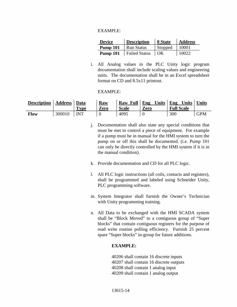
13615-14
EXAMPLE:
Device Description 0 State Address Pump 101 Run Status Stopped 10001 Pump 101 Failed Status OK 10022
i. All Analog values in the PLC Unity logic program
documentation shall include scaling values and engineering units. The documentation shall be in an Excel spreadsheet format on CD and 8.5x11 printout.
EXAMPLE: Description Address Data
Type Raw Zero
Raw Full Scale
Eng Units Zero
Eng Units Full Scale
Units
Flow 300010 INT 0 4095 0 300 GPM j. Documentation shall also state any special conditions that
must be met to control a piece of equipment. For example if a pump must be in manual for the HMI system to turn the pump on or off this shall be documented. (i.e. Pump 101 can only be directly controlled by the HMI system if it is in the manual condition).
k. Provide documentation and CD for all PLC logic. l. All PLC logic instructions (all coils, contacts and registers),
shall be programmed and labeled using Schneider Unity, PLC programming software.
m. System Integrator shall furnish the Owner’s Technician
with Unity programming training. n. All Data to be exchanged with the HMI SCADA system
shall be “Block Moved” to a contiguous group of “Super blocks” that contain contiguous registers for the purpose of read write routine polling efficiency. Furnish 25 percent spare “Super blocks” in-group for future additions.
EXAMPLE: 40206 shall contain 16 discrete inputs 40207 shall contain 16 discrete outputs 40208 shall contain 1 analog input 40209 shall contain 1 analog output

13615-15
All “Super block” register used shall contain the prefix
“HMI” in its description label for ease of identifying in its logic.
o. All analog I/O programming shall be based on a range
of 0 to 4095 bits.
p. To simplify program troubleshooting, PLC Unity logic program shall be written in a segment specific format as logic relates to field device control loops. (i.e. “For Example only”: Unity logic written for chlorine pacing system shall be contained in segment 07, logic to start and stop constant speed transfer pumps shall be contained in segment 08, etc.). Furnish Unity logic segment table of contents document listing segment numbers and control loop descriptions.
d. Relays: 1. Relays shall be provided as necessary to perform switching
functions required of control panels and other control circuits. All relays shall have screw type terminal interface. Terminals shall have a permanent, legible identification. Relays shall be mounted such that the terminal identifications are clearly visible and all terminals are readily accessible.
2. General-purpose relays shall be used for logic and
switching power to external loads and shall be DIN rail mounted, general purpose, medium power, and industrial type. Minimum mechanical life expectancy shall be 10,000,000 operations and electrical life expectancy of 100,000 operations at rated load. They shall be of the dust cover enclosed, plug-in type, with 8 or 11 pin, screw terminal, snap-on sockets. Relays shall have a maximum of three form C contacts rated for 10 amperes at 120V ac and be equipped with coil status indicator lamps and hold down springs. Relays shall be as manufactured by Potter-Brumfield series KRPA, KUP, or Omron Type G2R or approved equal.

13615-16
e. Power Supplies: 1. Provide dc power supplies as required to power instruments
requiring external dc power, including two-wire transmitters, dc relays.
2. Power supplies shall convert 120V ac, 60-Hz power to dc
power of the appropriate voltage(s) with sufficient voltage regulation and ripple control to assure that the instruments being supplied can operate within their required tolerances.
3. Output over voltage and over current protective devices
shall be provided with the power supply to protect the instruments from damage due to power supply failure and to protect the power supply from damage due to external failure. Provide NEMA 1 enclosure for all power supplies. Power supplies shall be DIN rail mounted such that dissipated heat does not adversely affect other components.
4. Power supplies shall be manufactured by Omron or Equal. f. Internal Panel Lights and Service Outlets: 1. Panels shall be internally lighted by LED lights, provided
with protective shields and an on/off toggle switch. LED lights shall be capable of illuminating all areas within the control panel. LED light output shall be equivalent to one (1) 40W fluorescent lamp mounted every four (4) feet of panel width.
2. Panels shall be provided with a 15-amp, 120-volt, service
outlet circuit within the back-of-panel area. The circuit shall be provided with three-wire, 120-volt, 15-ampere, duplex receptacles, one for every 4 feet of panel width (two minimum per panel) and spaced evenly along the back-of-panel area.
g. Wiring: Wiring within panels, consoles, racks, and cabinets shall
meet the following requirements: 1. AC power wiring shall be 600 VAC, 12 AWG tinned
stranded unless otherwise noted. 2. All Discrete Output control wiring to be orange in color,
300 VAC no less than, 16 AWG, Tinned Stranded Copper
13615-17
type B/N 16/19 or Belden 8500 or XHHW, insulated wire or equal.
3. All Discrete Input control wiring to be red in color, 300
VAC no less than, 16 AWG, Tinned Stranded Copper type B/N 16/19 or Belden 8500 or XHHW, insulated wire or equal.
4. Control wiring routed to MCC and field shall be no less
than 14 AWG multi-conductor Tray Cable, Stranded Copper type PVC, THWN or XHHW, insulated wire or equal.
5. All internal analog wiring, (PLC to field terminal), shall be
properly labeled and color coded Black for positive and White for negative polarity, no less than 18 AWG, Shielded Tinned Stranded Copper type Belden or equal.
6. All analog field signal cable exiting enclosure, outer jacket
shall be labeled with dot matrix printed shrink tube type wire labels. All shield drain wire shall be insulated and properly terminated per ISA and OEM standards. Labels shall identify terminal number, PLC logic reference number and affiliated process variable, properly color coded white for positive and black negative, no less than 16 AWG, Shielded Stranded Tinned Copper Signal type wire, Belden # 8719 or equal.
7. Wiring shall be numbered and tagged at each termination.
Heat shrunk dot matrix wire markers shall be provided at each wire termination point internal and external to each panel(s). Wire tags shall be marked with legible machine printed markings and numbers. Adhesive or taped on tags will not be accepted. Each wire shall have a unique tag number assigned and be clearly identified on the approved shop drawings. Tagging scheme shall identify the designated component tag and terminal number destination.
8. Wiring for special signals such as communications, digital
data, and multiplexed signals shall be labeled and use manufacturer's standard cables.
9. All wires to internal components shall be connected to the
"inside" of the field interface terminal strip. All wires to external components shall be connected to the "outside" of

13615-18
the field interface terminal strip. No more than two wires shall be connected to any one terminal point.
10. All panel wiring not run in wire ducts shall be bundled and
tied. 11. Wiring shall not be spliced or tapped except at device
terminals or terminal blocks. 12. Control and signal wiring shall be restrained by plastic ties
or ducts. Hinge wiring shall be secured at each end so that any bending or twisting will be around the longitudinal axis of the wire and the bend area shall be protected with a sleeve.
13. Where panel components are provided for future
equipment, wiring from the components to the panel terminal blocks shall be provided.
h. Wire Color Coding 1. Power Wiring: Phase A shall be black with brown phasing
tape, Phase B black with orange tape, and Phase C black with yellow tape.
2. Internally powered AC Control Wiring: Control panel
wiring associated with control circuits that are de-energized when the main panel disconnect is opened shall be color coded "Red".
3. Externally powered AC Control Wiring: Control panel
wiring associated with control circuits that remain "Hot" when the main panel disconnect is opened shall be color coded "Yellow".
4. All yellow wiring leaving panels shall be brought to an
isolated set of terminal blocks. 5. Low voltage, DC Wiring: Blue (DC+); White with Blue or
White with red and black -tracer (DC-). 6. DC Control Wiring: Dark Blue (+) and White with Blue
tracer (-). 7. Neutral: White

13615-19
Exception: Where prefabricated wire bundles are used, it is
permissible to identify the neutral at every termination with a white shrink tube at least 12 inches long.
8. Ground: Green 9. Field interface wiring shall be black and white pairs unless
otherwise noted or required by the National Electrical Code.
10. Intrinsically safe Light Blue 11. 24 VAC power wire shall be orange and brown. i. Wire Duct 1. Panel wire duct shall be provided between each row of
components and adjacent to each terminal strip. Wire ducts shall be a minimum of one inch wide and three inches deep with removable snap-on covers and perforated walls for easy wire entrance. Wire ducts shall be constructed of non-metallic materials with voltage insulation in excess of the maximum voltage carried therein.
2. Empty panel wire duct shall be provided for all field
connections to the terminal blocks. 3. A minimum of two inches shall be provided between wire
duct and terminal block assemblies 4. Wiring duct shall not be filled to more than 60% visible fill. j. Wiring Interface: All wiring including spares entering or leaving
each panel, console, rack or cabinet shall be terminated and identified as follows:
1. Analog and discrete signal wiring shall be terminated at
numbered terminal blocks. All wire shall be labeled with terminal number and PLC logic reference number.
2. Wiring for special signals such as communications, digital
data, and multiplexed signals may be terminated at manufacturer's standard connectors.
13615-20
k. Terminal Blocks: Terminal blocks for panels, consoles, racks, and cabinets shall meet the following requirements:
1. All terminal blocks shall be 600-volt rated and shall be
provided for termination of all circuits entering or leaving all panels. Terminal blocks shall have screw clamp compression, dead front barriers with current bar providing direct contact with wire between the compression screw and yoke. Yoke, current bar, and clamping screw shall be constructed of high strength and high conductivity metal. Yoke assembly shall guide all strands of wire into the terminal. Current bar shall provide dependable vibration-proof connections. Terminals shall be constructed to allow connection of wires without any special preparation other than stripping. Individual terminals shall be rail mounted to create a complete assembly such that jumpers can be installed with no loss of space on terminal or rail.
2. Terminal block components shall be sized to allow
insertion of all necessary wire sizes and types. Legible, factory machine printed markings and numbers shall be provided for terminal block identifications on both the inside and outside tracks of the terminal block assembly. Terminal blocks shall be numbered in numerical order.
3. Sufficient terminal blocks shall be provided to terminate all
wires routed to the panel, all spare points and spare conductors. In addition, the greatest of 20 percent or four unused spare terminals shall be provided
4. All connections for future functions shall be wired to
numbered terminal blocks, grouped separate from the terminal blocks in use. Terminal blocks shall be grouped to keep 120V ac circuits separate from the 24V dc circuits.
5. Terminal blocks shall be CSA certified and UL approved. 6. Control type terminal blocks shall be as manufactured by
WAGO, Entrelec, SQ-D or Owner approved equal. Analog signals (4-20 mA dc) shall be connected to knife type disconnect terminal. Shields required to be grounded shall be terminated. Signal shields shall be grounded at one point within a loop. Use blocks when passing the shields through.

13615-21
l. Grounding: Panels, consoles, racks and cabinets shall be provided with an isolated tinned copper grounding bus and lugs for all signal and shield ground connections. This ground bus shall be grounded at a common signal ground point. The signal grounding system shall meet National Electrical Code requirements. (See section 16450 Grounding System)
1. Each analog loop shall be grounded at a single point for the
loop. This single point shall be at location of the dc power supply for the loop. Keep all in separate conduit away from parallel runs or AC wiring.
2. Each analog loop shall have its wire shields connected to
ground at a single point for the loop. Shields shall be grouped and connected to ground at the same point as the analog signal ground.
m. Analog Signal Isolators and Surge Protectors: Instruments on
different panels, cabinets, or enclosures shall not be wired in series. Provide din rail mount analog signal isolators as manufactured by Moore Industries model SCX or M-Systems model M2VS, for analog signals that are sent from one panel or cabinet to another. All analog signals entering or leaving the control system shall be protected at both ends of loop by a surge arrester as manufactured by EDCO PC642C-036X or equal. Surge arresters shall be labeled.
2.04 TRANSFER METERING SYSTEM 1. Enclosure: a. Free-standing panels shall be provided with adequate internal
bracing to support the weight of all instruments and wiring. Internal bracing shall permit panel lifting without racking or distortion. Panel shall be NEMA 4X 316 stainless steel, R-6 insulted rated. All doors shall be rubber gasketed.
b. Removable lifting rings designed to facilitate simple, safe rigging
and lifting of the panel during installation shall be provided. Plugs shall be provided to fill the lifting ring holes after installation and shall match the panel color.
c. When applicable, free-standing cabinets shall match adjacent free-
standing cabinets in height, depth, general access, and color, unless

13615-22
otherwise noted. Panels shall not require any additional external supports or bracing to maintain freestanding integrity.
d. All installation details shall be verified by the Contractor/Supplier.
Unless otherwise noted, all panels shall be properly sized to fit in the allotted spaces as noted or shown in the Contract Drawings.
e. The panels shall be so constructed that no seams or bolt heads are
visible when viewed from the front. Panel cutouts for instruments and other devices (e.g., lights and switches) shall be punched, or drilled and smoothly finished with rounded edges.
f. Provide steel angle and/or plate stiffeners on the back of the panel
face to prevent panel deflection under instrument loading or operation. Internally, the panels shall be supplied with a structural steel framework for instrument support purposes and panel bracing. The internal framework shall permit panel lifting without racking or distortion. Provide removable lifting rings designed to facilitate simple, safe rigging and lifting of the panel during installation. Where two or more panels are shown mounted immediately adjacent to one another, they shall be securely bolted together with their front faces parallel. All internal components shall be mounted on removable subpans and not directly to the enclosures. Subpans shall be painted with a white enamel. Print storage pockets shall be provided on the inside of each panel. Its size shall be sufficient to hold all of the prints required to service the equipment. All control operations and overload reset shall be accessible without opening panel.
g. Each panel shall be provided with full height, fully gasketed access
doors where shown. Doors shall be provided with three-point latches. Handles shall be "D" ring, foldable type. All panel access doors shall be provided with full length, continuous, piano type, steel hinges with steel pins.
h. Freestanding panels shall be internally lighted by 30-watt min LED
lamps, provided with protective shields and a switch box mounted control switch. One light shall be provided for every 3.0 feet of panel width.
i. Panel shall permit continuous operation of all components with
external ambient temperatures of up to 100° F. The supplier shall submit to the Owner a heat dissipation summary with calculations for each panel furnished to support the fact that the panel and internal components have been designed to operate properly in the

13615-23
exposed environment. Heat dissipation shall be maximums and shall be given in BTU/Hr. Internal panel temperatures shall be maintained below 85° F.
j. Panels shall be provided with external conditioners as required to
prevent excessive temperature buildup as manufactured by Mclean Midwest "Slimboy" series with coated coils or equal. All temperature control equipment shall be controlled by a thermostat. Panels that are located outdoors shall not have vents open to the atmosphere and shall be provided with sun shields. Hardware shall be corrosion resistant for outdoor environments.
i. Panels shall be manufactured by Henessy Type TD or Equal. PART 3 - EXECUTION 3.01 GENERAL A. Instrumentation and accessory equipment shall be installed in accordance with
specification section 13300 and as specified herein. B. Unless specifically shown otherwise in the Drawings, direct reading or electrical
transmitting instrumentation shall not be mounted on process piping. Instrumentation shall be mounted on instrument racks or stands as detailed on the installation detail drawings. All instrumentation connections shall be provided with shutoff and drain valves. For differential pressure transmitters, three-way valve manifolds shall also be provided. For slurries, chemical or corrosive fluids, diaphragm seals with flushing connections shall be provided.
C. All piping to and from field instrumentation shall be provided with necessary
unions, test tees, couplings, adapters, and shut-off valves. D. Field instruments requiring power supplies shall be provided with local electrical
shut-offs and fuses as required. E. The shield on each process instrumentation cable shall be continuous from source
to destination and be grounded as directed by the manufacturer of the instrumentation equipment, but in no case shall more than one ground point be employed for each shield.
F. Lifting rings shall be removed from all panels and assemblies once in position.
Plugs of the same color as the panel shall then be installed in the holes.

13615-24
G. System Supplier shall coordinate the installation, placing and location of system components, their connections to the process equipment panels, cabinets and devices, subject to the Engineer's approval.
H. System Supplier shall ensure that all field wiring for power and signal circuits are
in accordance with best industry practice, and provide for all necessary system grounding to insure a satisfactory functioning installation.
I. Warranty per specification section 01740.
J. Manufacturer’s certification per 01650. 3.02 TRAINING
A. System Integrator shall furnish the Owner’s Technician with Basic PLC Operation training.
B. Provide instruction on (2) 8-hour working shifts to accommodate the Owner’s personnel schedule.
END OF SECTION