diversity techniques presentation material
TRANSCRIPT

Diversity Techniques
Vasileios Papoutsis
Wireless Telecommunication LaboratoryDepartment of Electrical and Computer Engineering
University of PatrasPatras, GreeceUNIVERSITY OF PATRAS ELECTRICAL &
COMPUTER ENG. DEPT. WIRELESS TELECOMMUNICATION LABORATORY No.1

Outline
• Introduction
• Diversity Techniques
• Diversity Combining Techniques
• MISO / OFDMA scheme
• Conclusions
UNIVERSITY OF PATRAS ELECTRICAL & COMPUTER ENG. DEPT. WIRELESS
TELECOMMUNICATION LABORATORY No.2

Challenges of Wireless Communication
• High Data Rate, seamless and high mobility requirements
• Spectral efficiency challenge (2-10 b/s/Hz)• Frequency selectivity due to large bandwidth
requirements• High System Capacity• Seamless coverage and support across different
networks, devices, and media forms• Reliable Communications
Harsh wireless channelScarce radio spectrumEnergy constraint
UNIVERSITY OF PATRAS ELECTRICAL & COMPUTER ENG. DEPT. WIRELESS
TELECOMMUNICATION LABORATORY No.3
UNIVERSITY OF PATRAS ELECTRICAL & COMPUTER ENG. DEPT. WIRELESS
TELECOMMUNICATION LABORATORY
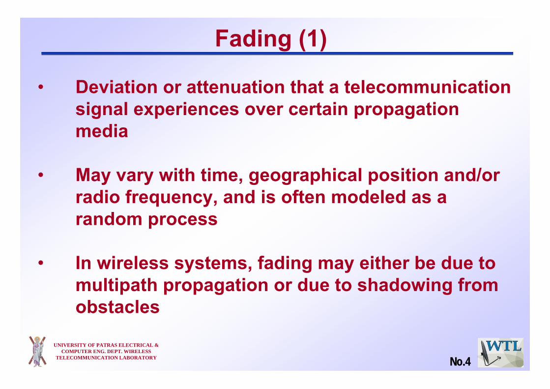
Fading (1)
• Deviation or attenuation that a telecommunication signal experiences over certain propagation media
• May vary with time, geographical position and/or radio frequency, and is often modeled as a random process
• In wireless systems, fading may either be due to multipath propagation or due to shadowing from obstacles
No.4

UNIVERSITY OF PATRAS ELECTRICAL & COMPUTER ENG. DEPT. WIRELESS
TELECOMMUNICATION LABORATORY
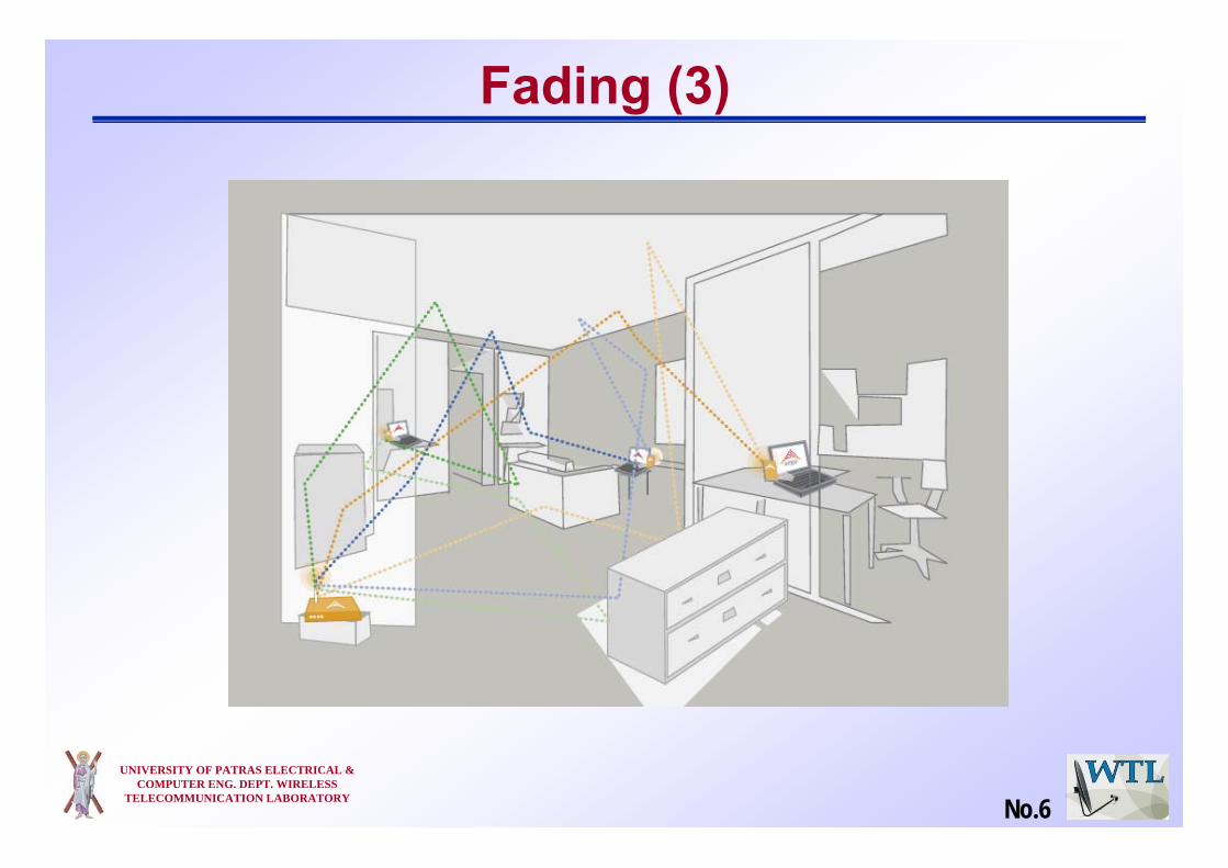
• Reflectors in the environment surrounding a transmitter and receiver create multiple paths that a transmitted signal can traverse
• The receiver sees the superposition of multiple copies of the transmitted signal, each traversing a different path
• Each signal copy will experience differences in attenuation, delay and phase shift while travelling from the source to the receiver
• This can result in either constructive or destructive interference, amplifying or attenuating the signal power seen at the receiver
• Strong destructive interference is frequently referred to as a deep fade and may result in temporary failure of communication due to a severe drop in the channel signal-to-noise ratio
Fading (2)
No.5
UNIVERSITY OF PATRAS ELECTRICAL & COMPUTER ENG. DEPT. WIRELESS
TELECOMMUNICATION LABORATORY
Fading (3)
No.6

Motivation of Diversity Techniques
• If a fading radio signal is received through only one channel, then in a deep fade, the signal could be lost, and there is nothing that can be done
• Diversity is a way to protect against deep fades, a choice to combat fading
• The key: create multiple channels or branches that have uncorrelated fading
UNIVERSITY OF PATRAS ELECTRICAL & COMPUTER ENG. DEPT. WIRELESS
TELECOMMUNICATION LABORATORY No.7

Basic Diversity Techniques
• Diversity combats fading by providing the receiver with multiple uncorrelated replicas of the same information bearing signal
• There are several types of receiver diversity methods
Time DiversityFrequency DiversityMultiuser DiversitySpace Diversity
UNIVERSITY OF PATRAS ELECTRICAL & COMPUTER ENG. DEPT. WIRELESS
TELECOMMUNICATION LABORATORY No.8

Basic Diversity Combining Techniques• Once you have created two or more channels or
branches that have uncorrelated fading, what do you do with them?
• Techniques applied to combine the multiple received signals of a diversity reception device into a single improved signal
Selection Combining (SC)Feedback or Scanning Combining (FC or SC)Maximal Ratio Combining (MRC)Equal Gain Combining (EGC)Zero Forcing (ZF)Minimum Mean Square Error (MMSE)
UNIVERSITY OF PATRAS ELECTRICAL & COMPUTER ENG. DEPT. WIRELESS
TELECOMMUNICATION LABORATORY No.9

Outline
• Introduction
• Diversity Techniques
• Diversity Combining
• MISO / OFDMA scheme
• Conclusions
UNIVERSITY OF PATRAS ELECTRICAL & COMPUTER ENG. DEPT. WIRELESS
TELECOMMUNICATION LABORATORY No.10

Time Diversity (1)
• Transmission in which signals representing the same information are sent over the same channel at different times
• The delay between replicas > coherence time uncorrelated channels
• Use coding and interleaving (it breaks the memory of the channel, not all bits of the codeword are likely to fall into a deep fade)
• It consumes extra transmission time
UNIVERSITY OF PATRAS ELECTRICAL & COMPUTER ENG. DEPT. WIRELESS
TELECOMMUNICATION LABORATORY No.11

Time Diversity (2)• The codewords are
transmitted over consecutive symbols (top) and interleaved (bottom)
• A deep fade will wipe out the entire codeword in the former case but only one coded symbol from each codeword in the latter
• In the latter case, each codeword can still be recovered from the other three unfaded symbols
UNIVERSITY OF PATRAS ELECTRICAL & COMPUTER ENG. DEPT. WIRELESS
TELECOMMUNICATION LABORATORY No.12

UNIVERSITY OF PATRAS ELECTRICAL & COMPUTER ENG. DEPT. WIRELESS
TELECOMMUNICATION LABORATORY
Time Diversity (3)
• Error probability as a function of SNR for different numbers of diversity branches L
No.13
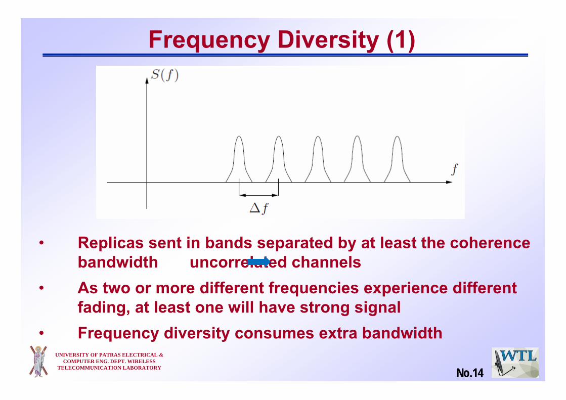
Frequency Diversity (1)
• Replicas sent in bands separated by at least the coherence bandwidth uncorrelated channels
• As two or more different frequencies experience different fading, at least one will have strong signal
• Frequency diversity consumes extra bandwidth UNIVERSITY OF PATRAS ELECTRICAL &
COMPUTER ENG. DEPT. WIRELESS TELECOMMUNICATION LABORATORY No.14

UNIVERSITY OF PATRAS ELECTRICAL & COMPUTER ENG. DEPT. WIRELESS
TELECOMMUNICATION LABORATORY
Frequency Diversity (2)
• Sending an information symbol every L symbol times
• Only one symbol can be transmitted every delay spread
• Once one tries to transmit symbols more frequently than the coherence bandwidth, inter-symbol interference (ISI) occurs
No.15

UNIVERSITY OF PATRAS ELECTRICAL & COMPUTER ENG. DEPT. WIRELESS
TELECOMMUNICATION LABORATORY
Multiuser Diversity
• Opportunistic user scheduling at either the transmitter or the receiver
• In a large system with users fading independently, there is likely to be a user with a very good channel at any time
• Transmitter selects the best user among candidate receivers according to the qualities of each channel between the transmitter and each receiver
No.16

UNIVERSITY OF PATRAS ELECTRICAL & COMPUTER ENG. DEPT. WIRELESS
TELECOMMUNICATION LABORATORY
OFDMA (1)• Orthogonal Frequency Division Multiple Access
(OFDMA) exploits multiuser diversity.
• Multiuser version of the popular Orthogonal Frequency Division Multiplexing (OFDM) digital modulation scheme which combats ISI
• Superior performance in frequency-selective fading wireless channels
• Modulation and multiple access scheme used in latest wireless systems such as IEEE 802.16e (Mobile WiMAX)
No.17

UNIVERSITY OF PATRAS ELECTRICAL & COMPUTER ENG. DEPT. WIRELESS
TELECOMMUNICATION LABORATORY
• Total bandwidth is divided into subcarriers.• Multiple access is achieved by assigning subsets
of subcarriers to individual users• A subcarrier is exclusively assigned to a user• Dynamic subcarrier assignment
OFDMA (2)
No.18

UNIVERSITY OF PATRAS ELECTRICAL & COMPUTER ENG. DEPT. WIRELESS
TELECOMMUNICATION LABORATORY
OFDMA (3)
No.19

UNIVERSITY OF PATRAS ELECTRICAL & COMPUTER ENG. DEPT. WIRELESS
TELECOMMUNICATION LABORATORY
• Two antennas separated by several wavelengths will not generally experience fades at the same time
• Space Diversity can be obtained by using two receiving antennas and switching instant-by-instant to whichever is best
Space Diversity (1)
No.20

UNIVERSITY OF PATRAS ELECTRICAL & COMPUTER ENG. DEPT. WIRELESS
TELECOMMUNICATION LABORATORY
Space Diversity (2)
• Several (receive) antennas (M)
• Uncorrelated branches Distance between antennas ≈ λ/2, where λ is the wavelength
• In GSM, λ ≈ 30 cm
No.21

UNIVERSITY OF PATRAS ELECTRICAL & COMPUTER ENG. DEPT. WIRELESS
TELECOMMUNICATION LABORATORY
Space Diversity (3)• Single-input, single-output (SISO) channel
No spatial diversity
• Single-input, multiple-output (SIMO) channelReceive diversity
• Multiple-input, single-output (MISO) channel Transmit diversity
• Multiple-input, multiple-output (MIMO) channelCombined transmit and receive diversity
No.22

UNIVERSITY OF PATRAS ELECTRICAL & COMPUTER ENG. DEPT. WIRELESS
TELECOMMUNICATION LABORATORY
Space Diversity (4)
No.23

UNIVERSITY OF PATRAS ELECTRICAL & COMPUTER ENG. DEPT. WIRELESS
TELECOMMUNICATION LABORATORY
Space Diversity (5)
No.24

UNIVERSITY OF PATRAS ELECTRICAL & COMPUTER ENG. DEPT. WIRELESS
TELECOMMUNICATION LABORATORY
Multiple Input Multiple Output (1)• MIMO uses independent
channel fading due to multipath propagation to increase capacity
• No extra bandwidth required
• Multiple independent samples of the same signal at the receiver give rise to diversity
No.25

UNIVERSITY OF PATRAS ELECTRICAL & COMPUTER ENG. DEPT. WIRELESS
TELECOMMUNICATION LABORATORY
Multiple Input Multiple Output (2)• MIMO system with NT transmit and NR receive
antennas
⎥⎥⎥
⎦
⎤
⎢⎢⎢
⎣
⎡
RTR
T
NNN
N
hh
hh
L
MOM
L
1
111
⎥⎥⎥
⎦
⎤
⎢⎢⎢
⎣
⎡
)(
)(1
kr
kr
RN
M⎥⎥⎥
⎦
⎤
⎢⎢⎢
⎣
⎡
)(
)(1
kx
kx
TN
M
⎥⎥⎥
⎦
⎤
⎢⎢⎢
⎣
⎡
)(
)(1
kn
kn
RN
M= +
)()()( kkk nxHr +⋅=: received vector: quasi-static channel matrix: transmitted vector: white Gaussian noise vector
H)(kr
)(kn)(kx
No.26

UNIVERSITY OF PATRAS ELECTRICAL & COMPUTER ENG. DEPT. WIRELESS
TELECOMMUNICATION LABORATORY
Shannon’s Law
Multiple Input Multiple Output (3)
No.27
UNIVERSITY OF PATRAS ELECTRICAL & COMPUTER ENG. DEPT. WIRELESS
TELECOMMUNICATION LABORATORY
Outline
• Introduction
• Diversity Techniques
• Diversity Combining Techniques
• MISO / OFDMA scheme
• Conclusions
No.28

UNIVERSITY OF PATRAS ELECTRICAL & COMPUTER ENG. DEPT. WIRELESS
TELECOMMUNICATION LABORATORY
Selection Combining
h1
h2
yx
MonitorSNR
Selectbranch
• Simple and cheap• Receiver selects branch with highest
instantaneous SNR• New selection made at a time that is the reciprocal
of the fading rate• This will cause the system to stay with the current
signal until it is likely the signal has faded
No.29
UNIVERSITY OF PATRAS ELECTRICAL & COMPUTER ENG. DEPT. WIRELESS
TELECOMMUNICATION LABORATORY
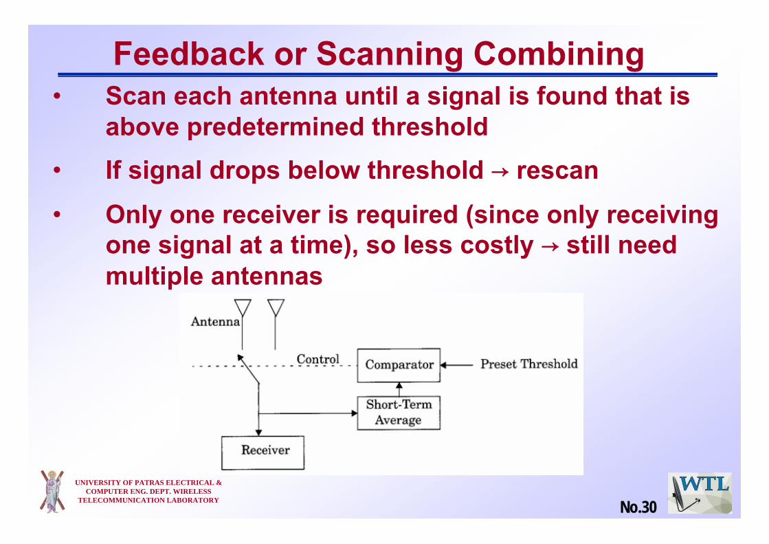
Feedback or Scanning Combining• Scan each antenna until a signal is found that is
above predetermined threshold• If signal drops below threshold → rescan• Only one receiver is required (since only receiving
one signal at a time), so less costly → still need multiple antennas
No.30

UNIVERSITY OF PATRAS ELECTRICAL & COMPUTER ENG. DEPT. WIRELESS
TELECOMMUNICATION LABORATORY
Maximal Ratio Combining
h1
h2
h1*
h2*
� yx
• All paths cophased and summed with optimal weighting to maximize combiner output SNR
• Optimal technique to maximize output SNR
• A means of combining the signals from all receiver branches, so that signals with a higher received power have a larger influence on the final output
No.31
UNIVERSITY OF PATRAS ELECTRICAL & COMPUTER ENG. DEPT. WIRELESS
TELECOMMUNICATION LABORATORY
Equal Gain Combining• Simplified method of Maximal Ratio Combining
• Combine multiple signals into one
• The phase is adjusted for each receive signal so that
The signal from each branch are co-phasedVectors add in-phase
• Better performance than selection diversity
No.32

UNIVERSITY OF PATRAS ELECTRICAL & COMPUTER ENG. DEPT. WIRELESS
TELECOMMUNICATION LABORATORY
ZF / MMSE
• MIMO system
• ZF: Pseudo inverse of the channel, simplest
• MMSE: Intermediate complexity and performance
)()()( kkk nxHr +⋅=
rHHrHHx * +− == 1)(ˆ
rHHHIx ⋅+= − HHNRSNR
1)1(ˆ
No.33

UNIVERSITY OF PATRAS ELECTRICAL & COMPUTER ENG. DEPT. WIRELESS
TELECOMMUNICATION LABORATORY
Outline
• Introduction
• Diversity Techniques
• Diversity Combining Techniques
• MISO / OFDMA scheme
• Conclusions
No.34

UNIVERSITY OF PATRAS ELECTRICAL & COMPUTER ENG. DEPT. WIRELESS
TELECOMMUNICATION LABORATORY No.35
System Model
• Base Station uses many antennas• A single antenna is available to each user• ZF beamforming inverts the channel matrix at the
transmitter in order to create orthogonal channels between the transmitter and the receiver. It is then possible to encode users individually
• Sum capacity is maximized while maintaining proportional fairness among users
• Proportional rate constraints are used• User selection procedure takes fairness into
account

UNIVERSITY OF PATRAS ELECTRICAL & COMPUTER ENG. DEPT. WIRELESS
TELECOMMUNICATION LABORATORY No.36
Problem Formulation (1)
• Where is the data rate of
user k per Hertz• if user k in the set Ai is selected in the
subcarrier n, otherwise
R1:R2:…:RK=γ1:γ2:…:γΚ

UNIVERSITY OF PATRAS ELECTRICAL & COMPUTER ENG. DEPT. WIRELESS
TELECOMMUNICATION LABORATORY No.37
Problem Formulation (2)
• is the equivalent signal to noise ratio
• and Bk is the BER requirement of user k
• is the Nt x 1beamforming vector for user k• PT is the total transmitted power• Nc is the total number of subcarriers• There are I possible combinations of users
transmitting on the same subcarrier, denoted as• is the allocated power to user k in the set Ai in
subcarrier n

UNIVERSITY OF PATRAS ELECTRICAL & COMPUTER ENG. DEPT. WIRELESS
TELECOMMUNICATION LABORATORY
Outline
• Introduction
• Diversity Techniques
• Diversity Combining Techniques
• MISO / OFDMA scheme
• Conclusions
No.38

Conclusions (1)
UNIVERSITY OF PATRAS ELECTRICAL & COMPUTER ENG. DEPT. WIRELESS
TELECOMMUNICATION LABORATORY
• Multipath fading is not an enemy but ally
• Diversity is used to provide the receiver with several replicas of the same signal
• Diversity techniques are used to improve the performance of the radio channel without any increase in the transmitted power
• As higher as the received signal replicas are decorrelated, as much as the diversity gain
No.39

UNIVERSITY OF PATRAS ELECTRICAL & COMPUTER ENG. DEPT. WIRELESS
TELECOMMUNICATION LABORATORY
Conclusions (2)• MRC outperforms the Selection Combining
• Equal gain combining (EGC) performs very close to the MRC
• Unlike the MRC, the estimate of the channel gain is not required in EGC
• Among different combining techniques MRC has the best performance and the highest complexity, SC has the lowest performance and the least complexity
No.40

Thank You!!!
UNIVERSITY OF PATRAS ELECTRICAL & COMPUTER ENG. DEPT. WIRELESS
TELECOMMUNICATION LABORATORY No.41