distributor catalogue - alliedheattransfer.com.au
TRANSCRIPT

DISTRIBUTOR CATALOGUEThis catalogue contains 4 sections:
Each section starts with a description and contents page followed by dimensional and performance data for the product listed in the section.
A Shell and Tube Heat Exchangers This section contains heat exchangers typically used
for cooling hydraulic, engine and marine systems with water.
B Air to Oil Cooling Systems For cooling oil with air both HP aluminium oil cooling
and ST steel oil cooling systems are listed in section B.
C Oil Cooler Panels Contains our ‘off the shelf’ stock of cooler panels
including aluminium, copper, steel, etc., along with replacements for common oil coolers.
D Accessories Section D includes strainers, 3 way thermo valves, thermo
by-pass valves, fans, temp operated fan switches, etc.
This catalogue is designed to assist our distributors by giving an easy reference to our product. We endeavour to keep the items listed in the catalogue on our shelves, however it pays to check availability with our office. It is important to remember that we are a heat exchanger company, we design and manufacture, so if you can not find what you need in the following pages, please contact us. In addition to making oil coolers, we also service them, so coolers can be sent to us for cleaning, repair and rebuild.
We support our distributors with backup advice, technical support and design software. For any heat exchanger enquiry contact us at the offices below.
www.alliedheattransfer.com.au
PERTH PH: 08 9455 5933 FAX: 08 9455 5944 19 Tacoma Circuit, Canning Vale, WA 6155
BRISBANE PH: 07 3375 1544 FAX: 07 3375 1566 18 Pradella Street, Darra, QLD 4076
EMAIL [email protected]
AHTI saddle stitched.indd 1 22/07/13 8:53 AM

AHTI saddle stitched.indd 2 22/07/13 8:53 AM

WATER TO OIL COOLERS/HEAT EXCHANGERS
Contents SECTION A page
DC and EC to PK range of Shell and Tube Oil Coolers 1-9
Performance of EC to PK Coolers 10-16
Stainless Steel Shell and Tube Oil Coolers 17
Exhaust Gas Heat Exchangers 18-19
Marine Cooling System 20
Header Tank Heat Exchanger 21-25
Shell and Tube Heat Exchangers
Basically a straightforward design and normally with cold water flowing through one, two, or three tube passes and hot oil over the outside of the tubes through the shell. Usually pumped in counter current, that is, oil flow out meeting water flow in. The ideal Shell and Tube exchanger is one with a fully floating and fully removable tube bundle. This design allows thermal expansion, longer service life and easier maintenance.
Materials used on the water side (tube side) are usually copper or cupro nickel, 90%cu and 10% nickel gives good protection against erosion of the tubes by salt or brine water. End bonnets can be cast iron where suitable corrosion inhibitors are used or cast bronze where water is raw or saline. Aluminium is an ideal material for the oil side shell. Stainless steel should not be used in salt-water applications.
Plate Heat Exchangers
There are two main types: the Gasketed plate heat exchanger, and the Brazed plate heat exchanger, the difference being that plates are separated by gaskets or fixed together by brazing.
Plate heat exchangers are efficient, compact and in the case of the gasket type, have a degree of versatility because plates can be added or subtracted if the duty changes.
Gasketed plate heat exchangers are custom built by adding the number of plates required to standard size frames.
Brazed Plate heat exchangers are as efficient as the gasketed type. The number of plates cannot be changed and they are not normally considered serviceable except for chemical cleaning. Generally used where both hot and cold fluids are clean. Materials used for plates are usually either 316 stainless steel or titanium for salt-water applications.
Always buy a quality heat exchanger. Cutting costs on cheaper varieties will come back to haunt you when water leaks into the oil system or visa versa.
Allied Heat Transfer International make and service heat exchangers. As a distributor of AHTI oil coolers and heat exchangers we want to keep you well informed, so please contact us if you have any questions on oil cooling or heat transfer.
WA
TER TO
OIL C
OO
LERS and
HEA
T EXC
HA
NG
ERS
section A
Water to oil coolers, commonly called heat exchangers, come in two main types – Shell and Tube and Plate type.
Use a heat exchanger when the required oil temperature from the cooler is lower than the ambient air temperature or where water is readily available, such as marine applications.
AHTI saddle stitched.indd 3 22/07/13 8:53 AM

www.alliedheattransfer.com.au
For more details or other sizes contact
PERTH PH: 08 9455 5933 FAX: 08 9455 5944 19 Tacoma Circuit, Canning Vale, WA 6155BRISBANE PH: 07 3375 1544 FAX: 07 3375 1566 18 Pradella Street, Darra, QLD 4076EMAIL [email protected]
WATER/OIL COOLER TECHNICAL DATA SHEET
OD oil port net dry Model No Size (mm) water pipe thread weight A / B / C (BSPP)
DC 50 205 x 51 22mm/28mm/32mm 1/2" 0.7
DC 60 240 x 51 22mm/28mm/32mm 1/2" 0.9
DC 90 314 x 51 22mm/28mm/32mm 1/2" 1.1
DC 120 396 x 51 22mm/28mm/32mm 1/2" 1.4
OIL COOLERSDC RANGE
NOW WITH RUBBER ENDS
SUITABLE FOR SALTWATER COOLING FLOW
MATERIALS Of CONSTRUCTION Tubes : 90/10 Cupro Nickel
Tubeplate : Naval Brass
End Caps : Rubber
Shell : Brass
3/8" available on special
order
section Apage 1
Suitable for Type Maximum sea water flow for end cover type gearbox transmitting
A/D B/E C/F None Straight/90˚ Straight/90˚ Straight/90˚
l/min l/min l/min l/min kW Hp
DC 50 60 90 120 180 75 100 DC 60 60 90 120 180 120 160 DC 90 60 90 120 180 150 200 DC 120 60 90 120 180 180 240
Maximum working oil pressure : 25 BARMaximum working water pressure : 3 BARMaximum working temperature : 125˚C
Typical examples of oil coolers fitted to marine transmissions with an oil inlet temperature of 80˚C and seawater temperature of 32˚C.
AHTI saddle stitched.indd 4 22/07/13 8:53 AM
www.alliedheattransfer.com.au
For more details or other sizes contact
PERTH PH: 08 9455 5933 FAX: 08 9455 5944 19 Tacoma Circuit, Canning Vale, WA 6155BRISBANE PH: 07 3375 1544 FAX: 07 3375 1566 18 Pradella Street, Darra, QLD 4076EMAIL [email protected]
A B C D MODEL NET OVERALL CONNECTION MOUNTING OIL CONNECTION NUMBER DRY WEIGHT LENGTH CENTRES CENTRES DIAMETER SIZE kg mm mm mm mm BSPP TAPPED M8x10
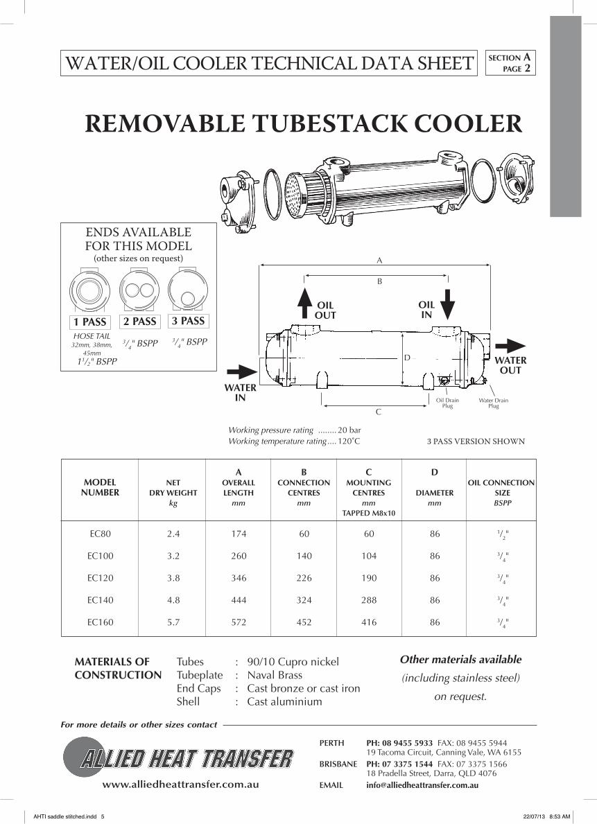
Working pressure rating ........ 20 bar Working temperature rating .... 120˚C
MATERIALS Of Tubes : 90/10 Cupro nickelCONSTRUCTION Tubeplate : Naval Brass End Caps : Cast bronze or cast iron Shell : Cast aluminium
Other materials available
(including stainless steel)
on request.
REMOVABLE TUBESTACK COOLER
A
B
OILOUT
OILIN
WATERIN
WATEROUT
D
C
Oil DrainPlug
Water DrainPlug
3 pASS vERSION SHOWN
1 PASS
ENDS AvAILABLE FOR THIS MODEL
(other sizes on request)
2 PASS 3 PASS
WATER/OIL COOLER TECHNICAL DATA SHEET
EC80 2.4 174 60 60 86 1/2"
EC100 3.2 260 140 104 86 3/4"
EC120 3.8 346 226 190 86 3/4"
EC140 4.8 444 324 288 86 3/4"
EC160 5.7 572 452 416 86 3/4"
3/4" BSPPHOSE TAIL
32mm, 38mm, 45mm
3/4" BSPP
section Apage 2
11/2" BSPP
AHTI saddle stitched.indd 5 22/07/13 8:53 AM

www.alliedheattransfer.com.au
For more details or other sizes contact
PERTH PH: 08 9455 5933 FAX: 08 9455 5944 19 Tacoma Circuit, Canning Vale, WA 6155BRISBANE PH: 07 3375 1544 FAX: 07 3375 1566 18 Pradella Street, Darra, QLD 4076EMAIL [email protected]
A B C D MODEL NET OVERALL CONNECTION MOUNTING OIL CONNECTION NUMBER DRY WEIGHT LENGTH CENTRES CENTRES DIAMETER SIZE kg mm mm mm mm BSPP TAPPED M8x12
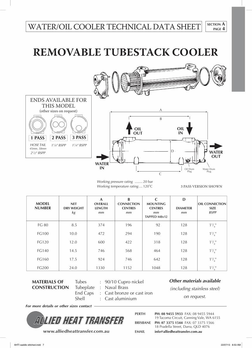
WATER/OIL COOLER TECHNICAL DATA SHEET
Working pressure rating ........ 20 bar Working temperature rating .... 120˚C
MATERIALS Of Tubes : 90/10 Cupro nickelCONSTRUCTION Tubeplate : Naval Brass End Caps : Cast bronze or cast iron Shell : Cast aluminium
Other materials available
(including stainless steel)
on request.
REMOVABLE TUBESTACK COOLER
A
B
OILOUT
OILIN
WATERIN
WATEROUT
D
C
Oil DrainPlug
Water DrainPlug
3 pASS vERSION SHOWN
1 PASS
ENDS AvAILABLE FOR THIS MODEL
(other sizes on request)
2 PASS 3 PASS
FC80 5.5 272 116 104 108 1"
FC100 6.3 358 202 190 108 1"
FC120 7.3 456 300 288 108 1"
FC140 9.4 584 428 288 108 1"
FC160 11.0 730 574 434 108 1"
1" BSPP
section Apage 3
HOSE TAIL45mm58mm
2" BSPP
1" BSPP
AHTI saddle stitched.indd 6 22/07/13 8:53 AM
www.alliedheattransfer.com.au
For more details or other sizes contact
PERTH PH: 08 9455 5933 FAX: 08 9455 5944 19 Tacoma Circuit, Canning Vale, WA 6155BRISBANE PH: 07 3375 1544 FAX: 07 3375 1566 18 Pradella Street, Darra, QLD 4076EMAIL [email protected]
A B C D MODEL NET OVERALL CONNECTION MOUNTING OIL CONNECTION NUMBER DRY WEIGHT LENGTH CENTRES CENTRES DIAMETER SIZE kg mm mm mm mm BSPP TAPPED M8x12
WATER/OIL COOLER TECHNICAL DATA SHEET
Working pressure rating ........ 20 bar Working temperature rating .... 120˚C
MATERIALS Of Tubes : 90/10 Cupro nickelCONSTRUCTION Tubeplate : Naval Brass End Caps : Cast bronze or cast iron Shell : Cast aluminium
Other materials available
(including stainless steel)
on request.
REMOVABLE TUBESTACK COOLER
A
B
OILOUT
OILIN
WATERIN
WATEROUT
D
C
Oil DrainPlug
Water DrainPlug
3 pASS vERSION SHOWN
1 PASS
ENDS AvAILABLE FOR THIS MODEL
(other sizes on request)
2 PASS 3 PASS
FG 80 8.5 374 196 92 128 11/4"
FG100 10.0 472 294 190 128 11/4"
FG120 12.0 600 422 318 128 11/4"
FG140 14.5 746 568 464 128 11/4"
FG160 17.5 924 746 642 128 11/4"
FG200 24.0 1330 1152 1048 128 11/4"
section Apage 4
11/4" BSPPHOSE TAIL45mm, 58mm
11/4" BSPP
21/2" BSPP
AHTI saddle stitched.indd 7 22/07/13 8:53 AM

www.alliedheattransfer.com.au
For more details or other sizes contact
PERTH PH: 08 9455 5933 FAX: 08 9455 5944 19 Tacoma Circuit, Canning Vale, WA 6155BRISBANE PH: 07 3375 1544 FAX: 07 3375 1566 18 Pradella Street, Darra, QLD 4076EMAIL [email protected]
A B C D MODEL NET OVERALL CONNECTION MOUNTING OIL CONNECTION NUMBER DRY WEIGHT LENGTH CENTRES CENTRES DIAMETER SIZE kg mm mm mm mm BSPP TAPPED M10x15
WATER/OIL COOLER TECHNICAL DATA SHEET
Working pressure rating ........ 20 bar Working temperature rating .... 120˚C
MATERIALS Of Tubes : 90/10 Cupro nickelCONSTRUCTION Tubeplate : Naval Brass End Caps : Cast bronze or cast iron Shell : Cast aluminium
Other materials available
(including stainless steel)
on request.
REMOVABLE TUBESTACK COOLER
A
B
OILOUT
OILIN
WATERIN
WATEROUT
D
C
Oil DrainPlug
Water DrainPlug
3 pASS vERSION SHOWN
1 PASS
ENDS AvAILABLE FOR THIS MODEL
(other sizes on request)
2 PASS 3 PASS
GL140 18 502 272 108 162 11/2"
GL180 21 630 400 236 162 11/2"
GL240 25 776 546 382 162 11/2"
GL320 30 954 724 560 162 11/2"
GL400 36 1156 926 762 162 11/2"
GL480 42 1360 1130 966 162 11/2"
section Apage 5
11/2" BSPP3" BSPP 11/2" BSPP
AHTI saddle stitched.indd 8 22/07/13 8:53 AM

www.alliedheattransfer.com.au
For more details or other sizes contact
PERTH PH: 08 9455 5933 FAX: 08 9455 5944 19 Tacoma Circuit, Canning Vale, WA 6155BRISBANE PH: 07 3375 1544 FAX: 07 3375 1566 18 Pradella Street, Darra, QLD 4076EMAIL [email protected]
A B C D MODEL NET OVERALL CONNECTION MOUNTING OIL CONNECTION NUMBER DRY WEIGHT LENGTH CENTRES CENTRES DIAMETER SIZE kg mm mm mm mm BSPP TAPPED M12x18
WATER/OIL COOLER TECHNICAL DATA SHEET
Working pressure rating ........ 20 bar Working temperature rating .... 120˚C
MATERIALS Of Tubes : 90/10 Cupro nickelCONSTRUCTION Tubeplate : Naval Brass End Caps : Cast bronze or cast iron Shell : Cast aluminium
Other materials available
(including stainless steel)
on request.
REMOVABLE TUBESTACK COOLER
A
B
OILOUT
OILIN
WATERIN
WATEROUT
D
C
Oil DrainPlug
Water DrainPlug
3 pASS vERSION SHOWN
1 PASS
ENDS AvAILABLE FOR THIS MODEL
(other sizes on request)
2 PASS 3 PASS
GK190 34 674 370 236 198 2"
GK250 39 820 516 382 198 2"
GK320 46 998 694 560 198 2"
GK400 54 1200 896 762 198 2"
GK480 62 1404 1100 966 198 2"
GK600 74 1708 1404 1270 198 2"
section Apage 6
2" BSPP2" BSPPFLANGE 104mm Ø
AHTI saddle stitched.indd 9 22/07/13 8:53 AM

www.alliedheattransfer.com.au
For more details or other sizes contact
PERTH PH: 08 9455 5933 FAX: 08 9455 5944 19 Tacoma Circuit, Canning Vale, WA 6155BRISBANE PH: 07 3375 1544 FAX: 07 3375 1566 18 Pradella Street, Darra, QLD 4076EMAIL [email protected]
A B C D MODEL NET OVERALL CONNECTION MOUNTING OIL CONNECTION NUMBER DRY WEIGHT LENGTH CENTRES CENTRES DIAMETER SIZE kg mm mm mm mm BSPP TAPPED M16x24
WATER/OIL COOLER TECHNICAL DATA SHEET
Working pressure rating ........ 20 bar Working temperature rating .... 120˚C
MATERIALS Of Tubes : 90/10 Cupro nickelCONSTRUCTION Tubeplate : Naval Brass End Caps : Cast bronze or cast iron Shell : Cast aluminium
Other materials available
(including stainless steel)
on request.
REMOVABLE TUBESTACK COOLER
A
B
OILOUT
OILIN
WATERIN
WATEROUT
D
C
Oil DrainPlug
Water DrainPlug
3 pASS vERSION SHOWN
1 PASS
ENDS AvAILABLE FOR THIS MODEL
(other sizes on request)
2 PASS 3 PASS
JK190 58 704 340 236 232 21/2"
JK250 66 850 486 382 232 21/2"
JK320 78 1028 664 560 232 21/2"
JK400 92 1230 866 762 232 21/2"
JK480 105 1434 1070 966 232 21/2"
JK600 126 1738 1374 1270 232 21/2"
section Apage 7
21/2" BSPP21/2" BSPPFLANGE 130mm Ø
AHTI saddle stitched.indd 10 22/07/13 8:53 AM

www.alliedheattransfer.com.au
For more details or other sizes contact
PERTH PH: 08 9455 5933 FAX: 08 9455 5944 19 Tacoma Circuit, Canning Vale, WA 6155BRISBANE PH: 07 3375 1544 FAX: 07 3375 1566 18 Pradella Street, Darra, QLD 4076EMAIL [email protected]
A B C D MODEL NET OVERALL CONNECTION MOUNTING OIL CONNECTION NUMBER DRY WEIGHT LENGTH CENTRES CENTRES DIAMETER SIZE kg mm mm mm mm BSPP TAPPED M16x24
WATER/OIL COOLER TECHNICAL DATA SHEET
Working pressure rating ........ 20 bar Working temperature rating .... 120˚C
MATERIALS Of Tubes : 90/10 Cupro nickelCONSTRUCTION Tubeplate : Naval Brass End Caps : Cast bronze or cast iron Shell : Cast aluminium
Other materials available
(including stainless steel)
on request.
REMOVABLE TUBESTACK COOLER
A
B
OILOUT
OILIN
WATERIN
WATEROUT
D
C
Oil DrainPlug
Water DrainPlug
3 pASS vERSION SHOWN
1 PASS
ENDS AvAILABLE FOR THIS MODEL
(other sizes on request)
2 PASS 3 PASS
PK190 81 754 330 236 278 3"
PK250 94 900 476 382 278 3"
PK320 110 1078 654 560 278 3"
PK400 125 1280 856 762 278 3"
PK480 140 1484 1060 966 278 3"
PK600 158 1788 1364 1270 278 3"
section Apage 8
3" BSPP3" BSPPFLANGE 150mm Ø
AHTI saddle stitched.indd 11 22/07/13 8:53 AM

www.alliedheattransfer.com.au
For more details or other sizes contact
PERTH PH: 08 9455 5933 FAX: 08 9455 5944 19 Tacoma Circuit, Canning Vale, WA 6155BRISBANE PH: 07 3375 1544 FAX: 07 3375 1566 18 Pradella Street, Darra, QLD 4076EMAIL [email protected]
* Maximum permttted oil flow on Shell Tellus 37 at 60˚CExceeding the maximum permitted water flow may cause tube failure.
MAXIMUM FLOW OF EC TO PK COOLERSTypical information for 3-pass units, for other configurations please contact us.
EC 80-1425-1 80 54 80 0.26 0.31 EC 100-1425-2 92 " " 0.49 0.44 EC 120-1425-3 77 " " 0.74 0.57 EC 140-1425-4 68 " " 0.97 0.71 EC 160-1425-5 64 " " 1.30 0.91 FC 80-1426-1 140 95 140 0.75 0.65 FC 100-1426-2 145 " " 1.10 0.84 FC 120-1426-3 116 " " 1.50 1.06 FC 140-1426-4 105 " " 2.00 1.35 FC 160-1426-5 96 " " 2.60 1.68 FG 80-1427-1 192 125 190 1.64 1.26 FG 100-1427-2 190 " " 2.40 1.56 FG 120-1427-3 160 " " 3.00 1.96 FG 140-1427-4 160 " " 3.90 2.42 FG 160-1427-5 145 " " 5.00 2.97 FG 200-1427-7 130 " " 7.58 4.53 GL 140-1428-2 300 225 330 3.60 3.10 GL 180-1428-3 285 " " 4.80 3.80 GL 240-1428-4 280 " " 6.30 4.60 GL 320-1428-5 270 " " 8.00 5.50 GL 400-1428-6 240 " " 10.00 6.60 GL 480-1428-7 235 " " 12.20 7.70 GK 190-1658-3 460 325 490 7.00 6.30 GK 250-1658-4 445 " " 9.00 7.50 GK 320-1658-5 430 " " 11.60 9.00 GK 400-1658-6 420 " " 14.60 10.60 GK 480-1658-7 400 " " 17.40 12.30 GK 600-1658-8 365 " " 22.10 14.70 JK 190-1661-3 830 460 700 9.70 8.80 JK 250-1661-4 740 " " 12.50 10.40 JK 320-1661-5 690 " " 16.10 12.50 JK 400-1661-6 650 " " 20.30 14.70 JK 480-1661-7 620 " " 24.20 17.10 JK 600-1661-8 600 " " 30.70 20.40 PK 190-1669-3 1600 700 1050 13.60 16.00 PK 250-1669-4 1240 " " 17.70 18.60 PK 320-1669-5 1060 " " 22.60 21.80 PK 400-1669-6 950 " " 28.50 25.30 PK 480-1669-7 890 " " 34.00 29.00 PK 600-1669-8 750 " " 42.50 34.40 PK 800-1669-9 630 " " 55.20 44.70
maximum maximum maximum internal internal TYPE oil flow sea water flow fresh water flow oil volume water volume
WATER/OIL COOLER TECHNICAL DATA SHEETsection Apage 9
AHTI saddle stitched.indd 12 22/07/13 8:53 AM

www.alliedheattransfer.com.au
For more details or other sizes contact
PERTH PH: 08 9455 5933 FAX: 08 9455 5944 19 Tacoma Circuit, Canning Vale, WA 6155BRISBANE PH: 07 3375 1544 FAX: 07 3375 1566 18 Pradella Street, Darra, QLD 4076EMAIL [email protected]
EC RANGE
WATER/OIL COOLER COOLING PERFORMANCE
20 40 60 80 100 120 140
28
24
20
16
12
8
4
10 20 30 40 50 60 70 80 90 100 110 120
140
120
100
80
60
40
20
35
30
25
20
15
10
5
5 10 15 20 25 30 35 40 45 50 55 60
Heat dissipation
kW D
ISSI
PATE
D w
hen
oil o
utle
t te
mpe
ratu
reex
ceed
s th
e w
ater
inle
t te
mpe
ratu
re b
y 25
˚C
Oil flow rate in litres per minute
Pres
sure
dro
p kP
a
Pres
sure
dro
p kP
a
Water flow (litre/min)Oil flow (litre/min)
Water pressure dropOil pressure dropWater at 25˚CShell Tellus 37 Oil at 50˚C outlet
For dimensions see water/oil cooler technical data sheet in this catalogue
EC160
EC140
EC120
EC100
EC80
EC160
EC140
EC80
EC120
EC160
EC140
EC120EC100
EC80
EC100
When the oil outlet temperature exceeds the water inlet temperature by other than 25˚C multiply the kW dissipation figure by the following correction factor –
The heat dissipation figures are based on a water flow rate which is 50% of the oil flow. For other water flow rates, multiply the dissipation figure by the following correction factor –
25% 50% 100%
0.8 1 1.2
15˚C 20˚C 25˚C 30˚C 35˚C
0.6 0.8 1 1.2 1.4Cor
rect
ion
fact
ors Temperature Difference Water flow Rate
section Apage 10
AHTI saddle stitched.indd 13 22/07/13 8:53 AM

www.alliedheattransfer.com.au
For more details or other sizes contact
PERTH PH: 08 9455 5933 FAX: 08 9455 5944 19 Tacoma Circuit, Canning Vale, WA 6155BRISBANE PH: 07 3375 1544 FAX: 07 3375 1566 18 Pradella Street, Darra, QLD 4076EMAIL [email protected]
Water flow (litre/min)
fC RANGE
50 70 90 110 130 150 170 190
32
28
24
20
16
12
8
4
10 20 30 40 50 60 70 80 90 100 110 120 130 140 150
140
120
100
80
60
40
20
35
30
25
20
15
10
5
10 20 30 40 50 60 70 80 90 100
kW D
ISSI
PATE
D w
hen
oil o
utle
t te
mpe
ratu
reex
ceed
s th
e w
ater
inle
t te
mpe
ratu
re b
y 25
˚C
Oil flow (litre/min)
Pres
sure
dro
p kP
a
Pres
sure
dro
p kP
a
Oil flow (litre/min)
Water pressure dropOil pressure dropWater at 25˚CShell Tellus 37 Oil at 50˚C outlet
For dimensions see water/oil cooler technical data sheet in this catalogue
FC160
FC160
FC140
FC80
FC120
FC100
FC160FC140FC120FC100FC80
When the oil outlet temperature exceeds the water inlet temperature by other than 25˚C multiply the kW dissipation figure by the following correction factor –
The heat dissipation figures are based on a water flow rate which is 50% of the oil flow. For other water flow rates, multiply the dissipation figure by the following correction factor –
25% 50% 100%
0.8 1 1.2
15˚C 20˚C 25˚C 30˚C 35˚C
0.6 0.8 1 1.2 1.4Cor
rect
ion
fact
ors Temperature Difference Water flow Rate
FC140
FC120
FC100
FC80
Heat dissipation
WATER/OIL COOLER COOLING PERFORMANCEsection Apage 11
AHTI saddle stitched.indd 14 22/07/13 8:53 AM

www.alliedheattransfer.com.au
For more details or other sizes contact
PERTH PH: 08 9455 5933 FAX: 08 9455 5944 19 Tacoma Circuit, Canning Vale, WA 6155BRISBANE PH: 07 3375 1544 FAX: 07 3375 1566 18 Pradella Street, Darra, QLD 4076EMAIL [email protected]
Water flow (litre/min)
fG RANGE
25 50 75 100 125 150 175 200 225 250 275 300
90
75
60
45
30
15
20 40 60 80 100 120 140 160 180 200 220 240
140
120
100
80
60
40
20
35
30
25
20
15
10
5
25 50 75 100 125 150
kW D
ISSI
PATE
D w
hen
oil o
utle
t te
mpe
ratu
reex
ceed
s th
e w
ater
inle
t te
mpe
ratu
re b
y 25
˚C
Oil flow (litre/min)
Pres
sure
dro
p kP
a
Pres
sure
dro
p kP
a
Oil flow (litre/min)
Water pressure dropOil pressure dropWater at 25˚CShell Tellus 37 Oil at 50˚C outlet
For dimensions see water/oil cooler technical data sheet in this catalogue
FG160
FG140
FG80
FG120 FG
100
FG160
FG140
FG120
FG100
FG80
When the oil outlet temperature exceeds the water inlet temperature by other than 25˚C multiply the kW dissipation figure by the following correction factor –
The heat dissipation figures are based on a water flow rate which is 50% of the oil flow. For other water flow rates, multiply the dissipation figure by the following correction factor –
25% 50% 100%
0.8 1 1.2
15˚C 20˚C 25˚C 30˚C 35˚C
0.6 0.8 1 1.2 1.4Cor
rect
ion
fact
ors Temperature Difference Water flow Rate
Heat dissipation
FG160
FG140
FG120
FG100
FG80
WATER/OIL COOLER COOLING PERFORMANCE section Apage 12
AHTI saddle stitched.indd 15 22/07/13 8:53 AM

www.alliedheattransfer.com.au
For more details or other sizes contact
PERTH PH: 08 9455 5933 FAX: 08 9455 5944 19 Tacoma Circuit, Canning Vale, WA 6155BRISBANE PH: 07 3375 1544 FAX: 07 3375 1566 18 Pradella Street, Darra, QLD 4076EMAIL [email protected]
30 60 90 120 150 180 210 240 270 300 330 360
140
120
100
80
60
40
20
35
30
25
20
15
10
5
25 50 75 100 125 150 175 200
Pres
sure
dro
p kP
a
Pres
sure
dro
p kP
a
Water flow (litre/min)Oil flow (litre/min)
Water pressure dropOil pressure dropWater at 25˚CShell Tellus 37 Oil at 50˚C outlet
For dimensions see water/oil cooler technical data sheet in this catalogue
GL480
GL400
GL180
GL320
GL240
GL140
GL480
GL400
GL180
GL320GL240
GL140
GL RANGE
100 125 150 175 200 225 250 275 300
120
105
90
75
60
45
30
kW D
ISSI
PATE
D w
hen
oil o
utle
t te
mpe
ratu
reex
ceed
s th
e w
ater
inle
t te
mpe
ratu
re b
y 25
˚C
Oil flow (litre/min)
When the oil outlet temperature exceeds the water inlet temperature by other than 25˚C multiply the kW dissipation figure by the following correction factor –
The heat dissipation figures are based on a water flow rate which is 50% of the oil flow. For other water flow rates, multiply the dissipation figure by the following correction factor –
25% 50% 100%
0.8 1 1.2
15˚C 20˚C 25˚C 30˚C 35˚C
0.6 0.8 1 1.2 1.4Cor
rect
ion
fact
ors Temperature Difference Water flow Rate
GL480 GL400
GL320
GL240
GL180
GL140
Heat dissipation
WATER/OIL COOLER COOLING PERFORMANCEsection Apage 13
AHTI saddle stitched.indd 16 22/07/13 8:53 AM

www.alliedheattransfer.com.au
For more details or other sizes contact
PERTH PH: 08 9455 5933 FAX: 08 9455 5944 19 Tacoma Circuit, Canning Vale, WA 6155BRISBANE PH: 07 3375 1544 FAX: 07 3375 1566 18 Pradella Street, Darra, QLD 4076EMAIL [email protected]
Water flow (litre/min)
GK RANGE
50 100 150 200 250 300 350 400 450 500 550 600
140
120
100
80
60
40
20
70
60
50
40
30
20
10
30 60 90 120 150 180 210 240 270 300 330 360
Pres
sure
dro
p kP
a
Pres
sure
dro
p kP
a
Oil flow (litre/min)
Water pressure dropOil pressure dropWater at 25˚CShell Tellus 37 Oil at 50˚C outlet
For dimensions see water/oil cooler technical data sheet in this catalogue
GK600
GK480
GK250
GK400 GK
320
GK190
GK190
GK250
GK320
GK400
GK480
GK600
150 200 250 300 350 400 450 500 550 600
350
300
250
200
150
100
50
kW D
ISSI
PATE
D w
hen
oil o
utle
t te
mpe
ratu
reex
ceed
s th
e w
ater
inle
t te
mpe
ratu
re b
y 25
˚C
Oil flow (litre/min)
Heat dissipation GK600
GK480
GK400
GK320
GK250
GK190
When the oil outlet temperature exceeds the water inlet temperature by other than 25˚C multiply the kW dissipation figure by the following correction factor –
The heat dissipation figures are based on a water flow rate which is 50% of the oil flow. For other water flow rates, multiply the dissipation figure by the following correction factor –
25% 50% 100%
0.8 1 1.2
15˚C 20˚C 25˚C 30˚C 35˚C
0.6 0.8 1 1.2 1.4
Cor
rect
ion
fact
ors Temperature Difference Water flow Rate
WATER/OIL COOLER COOLING PERFORMANCE section Apage 14
AHTI saddle stitched.indd 17 22/07/13 8:53 AM

www.alliedheattransfer.com.au
For more details or other sizes contact
PERTH PH: 08 9455 5933 FAX: 08 9455 5944 19 Tacoma Circuit, Canning Vale, WA 6155BRISBANE PH: 07 3375 1544 FAX: 07 3375 1566 18 Pradella Street, Darra, QLD 4076EMAIL [email protected]
Water flow (litre/min)
JK RANGE
75 150 225 300 375 450 525 600 675 750 825 900
400
350
300
250
200
150
100
50
75 150 225 300 375 450 525 600 675 750 825 900
140
120
100
80
60
40
20
35
30
25
20
15
10
5
50 100 150 200 250 300 350 400 450 500 550 600
Heat dissipation
kW D
ISSI
PATE
D w
hen
oil o
utle
t te
mpe
ratu
reex
ceed
s th
e w
ater
inle
t te
mpe
ratu
re b
y 25
˚C
Oil flow (litre/min)
Pres
sure
dro
p kP
a
Pres
sure
dro
p kP
a
Oil flow (litre/min)
Water pressure drop
Oil pressure drop
Water at 25˚C
Shell Tellus 37 Oil at 50˚C outlet
For dimensions see water/oil cooler technical data sheet in this catalogue
JK600
JK480
JK600
JK480
JK400
JK320
JK250
JK190
JK400
JK250
JK190
JK320
JK600
JK480
JK400
JK320
JK250
JK190
When the oil outlet temperature exceeds the water inlet temperature by other than 25˚C multiply the kW dissipation figure by the following correction factor –
The heat dissipation figures are based on a water flow rate which is 50% of the oil flow. For other water flow rates, multiply the dissipation figure by the following correction factor –
25% 50% 100%
0.8 1 1.2
15˚C 20˚C 25˚C 30˚C 35˚C
0.6 0.8 1 1.2 1.4
Cor
rect
ion
fact
ors Temperature Difference Water flow Rate
WATER/OIL COOLER COOLING PERFORMANCEsection Apage 15
AHTI saddle stitched.indd 18 22/07/13 8:53 AM

www.alliedheattransfer.com.au
For more details or other sizes contact
PERTH PH: 08 9455 5933 FAX: 08 9455 5944 19 Tacoma Circuit, Canning Vale, WA 6155BRISBANE PH: 07 3375 1544 FAX: 07 3375 1566 18 Pradella Street, Darra, QLD 4076EMAIL [email protected]
When the oil outlet temperature exceeds the water inlet temperature by other than 25˚C multiply the kW dissipation figure by the following correction factor –
The heat dissipation figures are based on a water flow rate which is 50% of the oil flow. For other water flow rates, multiply the dissipation figure by the following correction factor –
25% 50% 100%
0.8 1 1.2
15˚C 20˚C 25˚C 30˚C 35˚C
0.6 0.8 1 1.2 1.4
Cor
rect
ion
fact
ors Temperature Difference Water flow Rate
Water flow (litre/min)
PK RANGE
100 200 300 400 500 600 700 800 900 1000 1100 1200
600
525
450
375
300
225
150
75
100 200 300 400 500 600 700 800 900 1000 1100 1200
140
120
100
80
60
40
20
70
60
50
40
30
20
10
75 150 225 300 375 450 525 600 675 750 825 900
Heat dissipation
kW D
ISSI
PATE
D w
hen
oil o
utle
t te
mpe
ratu
reex
ceed
s th
e w
ater
inle
t te
mpe
ratu
re b
y 25
˚C
Oil flow (litre/min)
Pres
sure
dro
p kP
a
Pres
sure
dro
p kP
a
Oil flow (litre/min)
Water pressure dropOil pressure dropWater at 25˚CShell Tellus 37 Oil at 50˚C outlet
For dimensions see water/oil cooler technical data sheet in this catalogue
PK600
PK600
PK480
PK400
PK320PK250PK190
PK600 PK480
PK400PK320
PK190
PK250
PK480
PK400
PK320
PK250
PK190
WATER/OIL COOLER COOLING PERFORMANCE section Apage 16
AHTI saddle stitched.indd 19 22/07/13 8:53 AM

www.alliedheattransfer.com.au
For more details or other sizes contact
PERTH PH: 08 9455 5933 FAX: 08 9455 5944 19 Tacoma Circuit, Canning Vale, WA 6155BRISBANE PH: 07 3375 1544 FAX: 07 3375 1566 18 Pradella Street, Darra, QLD 4076EMAIL [email protected]
STAINLESS STEEL COOLERS
These extremely robust heat exchangers are built entirely from 316 stainless steel. Tubes are expanded into tubeplates and ends are removable for tube cleaning. please contact us to perform thermal calculations.
Working pressure rating : 30 BAR
Working temperature rating : 200˚C
C4 x ØN
BA
L
1 PASS OPTIONM
K
J
FG
H
3 PASS OPTIONM
K
J
FG
H
A B C D E f G H J K L M N mm mm mm mm mm mm mm mm mm mm BSPP (") BSPP (") mm
SB 4507-2 460 266 310 89 136 60 90 75 22 70 G1 G1 9SB 4507-4 734 540 584 89 136 60 90 75 22 70 G1 G1 9SB 4507-6 1114 920 964 89 136 60 90 75 22 70 G1 G1 9
SC 4508-4 764 520 584 114 160 80 110 90 28 85 G11/4 G11/4 9SC 4508-6 1144 900 964 114 160 80 110 90 28 85 G11/4 G11/4 9SC 4508-8 1652 1408 1472 114 160 80 110 90 28 85 G11/4 G11/4 9
SD 4509-4 764 510 584 141 194 100 130 105 35 100 G11/2 G11/2 11SD 4509-6 1134 890 964 141 194 100 130 105 35 100 G11/2 G11/2 11SD 4509-8 1652 1398 1472 141 194 100 130 105 35 100 G11/2 G11/2 11
SE 4510-4 804 490 584 168 220 130 160 120 45 120 G2 G2 11SE 4510-6 1184 870 964 168 220 130 160 120 45 120 G2 G2 11SE 4510-8 1692 1378 1472 168 220 130 160 120 45 120 G2 G2 11SE 4510-9 2200 1886 1980 168 220 130 160 120 45 120 G2 G2 11
SF 4511-4 8341 470 574 219 284 180 220 150 60 150 G21/2 G21/2 14SF 4511-6 1214 850 954 219 284 180 220 150 60 150 G21/2 G21/2 14SF 4511-8 1722 1358 1462 219 284 180 220 150 60 150 G21/2 G21/2 14SF 4511-9 2230 1866 1970 219 284 180 220 150 60 150 G21/2 G21/2 14
SG 4512-4 844 430 574 273 340 250 290 180 70 180 G3 G3 14SG 4512-6 1224 810 954 273 340 250 290 180 70 180 G3 G3 14SG 4512-8 1732 1318 1462 273 340 250 290 180 70 180 G3 G3 14SG 4512-9 2240 1826 1970 273 340 250 290 180 70 180 G3 G3 14
D
MODEL
section Apage 17
AHTI saddle stitched.indd 20 22/07/13 8:53 AM

www.alliedheattransfer.com.au
For more details or other sizes contact
PERTH PH: 08 9455 5933 FAX: 08 9455 5944 19 Tacoma Circuit, Canning Vale, WA 6155BRISBANE PH: 07 3375 1544 FAX: 07 3375 1566 18 Pradella Street, Darra, QLD 4076EMAIL [email protected]
These heat exchangers are designed to remove thermal energy from the exhaust gas of natural gas, diesel and bio-fuel engines and transfer it to the water circuit. The extracted heat can be used for space heating, domestic hot water and any industrial process that requires hot water.
Used in conjunction with jacket water, charge air, fuel and oil coolers, Bowman units can reclaim up to 60% of waste heat from an engine.
Fully welded stainless steel construction for reliability and durability.
GAS WATER
Working temperature 700˚C 110˚C
Working pressure 0.5 BAR 4 BARAB
L ¾"BSP
1"BSP
C
ØEØD
R-C
IS
water drain plugF
H
JØM
ØP
ØN
4 x ØK
EXHAUST GAS HEAT EXCHANGERS section Apage 18
A B C D E f H J K L M N P R Kgs mm mm mm mm mm mm mm mm mm mm mm mm mm
2-25-3737-4 754 540 584 60.3 100 75 83 60 9 RP¾" 34 75 4x11 16 10 2-25-3737-5 932 718 762 60.3 100 75 83 60 9 RP¾" 34 75 4x11 16 12
3-32-3738-5 962 718 762 89 140 60 75 70 9 RP1" 54 110 4x14 16 18 3-40-3738-6 1164 920 964 89 140 60 75 70 9 RP1" 54 110 4x14 16 20 3-60-3738-8 1672 1428 1472 89 140 60 75 70 9 RP1" 54 110 4x14 16 27
4-32-3739-5 992 698 762 114 160 80 90 85 9 RP1½" 66 130 4x14 22 24 4-40-3739-6 1194 900 964 114 160 80 90 85 9 RP1½" 66 130 4x14 22 28 4-60-3739-8 1702 1408 1472 114 160 80 90 85 9 RP1½" 66 130 4x14 22 42
5-32-3740-5 1032 688 762 141 190 100 105 100 11 RP2" 82 150 4x18 26 36 5-40-3740-6 1234 890 964 141 190 100 105 100 11 RP2" 82 150 4x18 26 39 5-60-3740-8 1742 1398 1472 141 190 100 105 100 11 RP2" 82 150 4x18 26 51
6-32-3741-5 1082 668 762 168 210 130 120 140 11 DN60* 104 170 4x18 28 51 6-40-3741-6 1284 870 964 168 210 130 120 140 11 DN60* 104 170 4x18 28 53 6-60-3741-8 1792 1378 1472 168 210 130 120 140 11 DN60* 104 170 4x18 28 75
8-32-3742-5 1152 648 752 219 240 180 150 180 14 DN80* 130 200 8x18 40 85 8-40-3742-6 1354 850 954 219 240 180 150 180 14 DN80* 130 200 8x18 40 98 8-60-3742-8 1862 1358 1462 219 240 180 150 180 14 DN80* 130 200 8x18 40 121
10-32-3743-5 1232 608 752 273 265 250 180 220 14 DN100* 154 225 8x18 55 132 10-40-3743-6 1434 810 954 273 265 250 180 220 14 DN100* 154 225 8x18 55 146 10-60-3743-8 1942 1318 1462 273 265 250 180 220 14 DN100* 154 225 8x18 55 181
12-32-3744-5 1332 538 738 324 320 300 220 270 18 DN150* 204 280 8x18 55 190 12-40-3744-6 1534 740 940 324 320 300 220 270 18 DN150* 204 280 8x18 55 208 12-60-3744-8 2042 1248 1448 324 320 300 220 270 18 DN150* 204 280 8x18 55 262
AHTI saddle stitched.indd 21 22/07/13 8:53 AM

www.alliedheattransfer.com.au
For more details or other sizes contact
PERTH PH: 08 9455 5933 FAX: 08 9455 5944 19 Tacoma Circuit, Canning Vale, WA 6155BRISBANE PH: 07 3375 1544 FAX: 07 3375 1566 18 Pradella Street, Darra, QLD 4076EMAIL [email protected]
Following are some typical examples of exhaust gas heat exchanger performance. For specific designs or larger sizes contact our sales department.
The figures below are a general guide and are not based on any particular natural gas engine. They assume an air/fuel ratio of 10.23 : 1 by volume, a fuel consumption of 0.34m3/kWh (measured at 1.013 bar and 15˚C) and and exhaust gas temperature of 600˚C and a water inlet temperature of 80˚C.
TYPE GEN SET RATING PERfORMANCE
Typical Exhaust Exhaust gas Heat Exhaust engine power gas flow outlet temperature recovery pressure drop kW kg/min ˚C kW kPa
2-25-3737-4 16 1.2 210 9.5 2.4 2-32-3737-5 16 1.2 170 10.5 2.8
3-32-3738-5 32 2.4 210 19 2.4 3-40-3738-6 32 2.4 170 21 2.8 3-60-3738-8 32 2.4 120 23 3.4
4-32-3739-5 60 4.5 210 35 2.2 4-40-3739-6 60 4.5 170 39 2.4 4-60-3739-8 60 4.5 120 43 3.0
5-32-3740-5 90 6.7 210 52 2.1 5-40-3740-6 90 6.7 170 57 2.4 5-60-3740-8 90 6.7 120 65 2.9
6-32-3741-5 140 10.5 210 82 2.2 6-40-3741-6 140 10.5 170 90 2.4 6-60-3741-8 140 10.5 120 101 3.0
8-32-3742-5 250 18.7 210 147 2.3 8-40-3742-6 250 18.7 170 160 2.5 8-60-3742-8 250 18.7 120 181 3.0
10-32-3743-5 400 30.0 210 236 2.4 10-40-3743-6 400 30.0 170 256 2.6 10-60-3743-8 400 30.0 120 288 3.1
12-32-3744-5 600 45.0 210 353 2.3 12-40-3744-6 600 45.0 170 380 2.5 12-60-3744-8 600 45.0 120 425 3.1
EXHAUST GAS HEAT EXCHANGERSsection Apage 19
AHTI saddle stitched.indd 22 22/07/13 8:53 AM
www.alliedheattransfer.com.au
For more details or other sizes contact
PERTH PH: 08 9455 5933 FAX: 08 9455 5944 19 Tacoma Circuit, Canning Vale, WA 6155BRISBANE PH: 07 3375 1544 FAX: 07 3375 1566 18 Pradella Street, Darra, QLD 4076EMAIL [email protected]
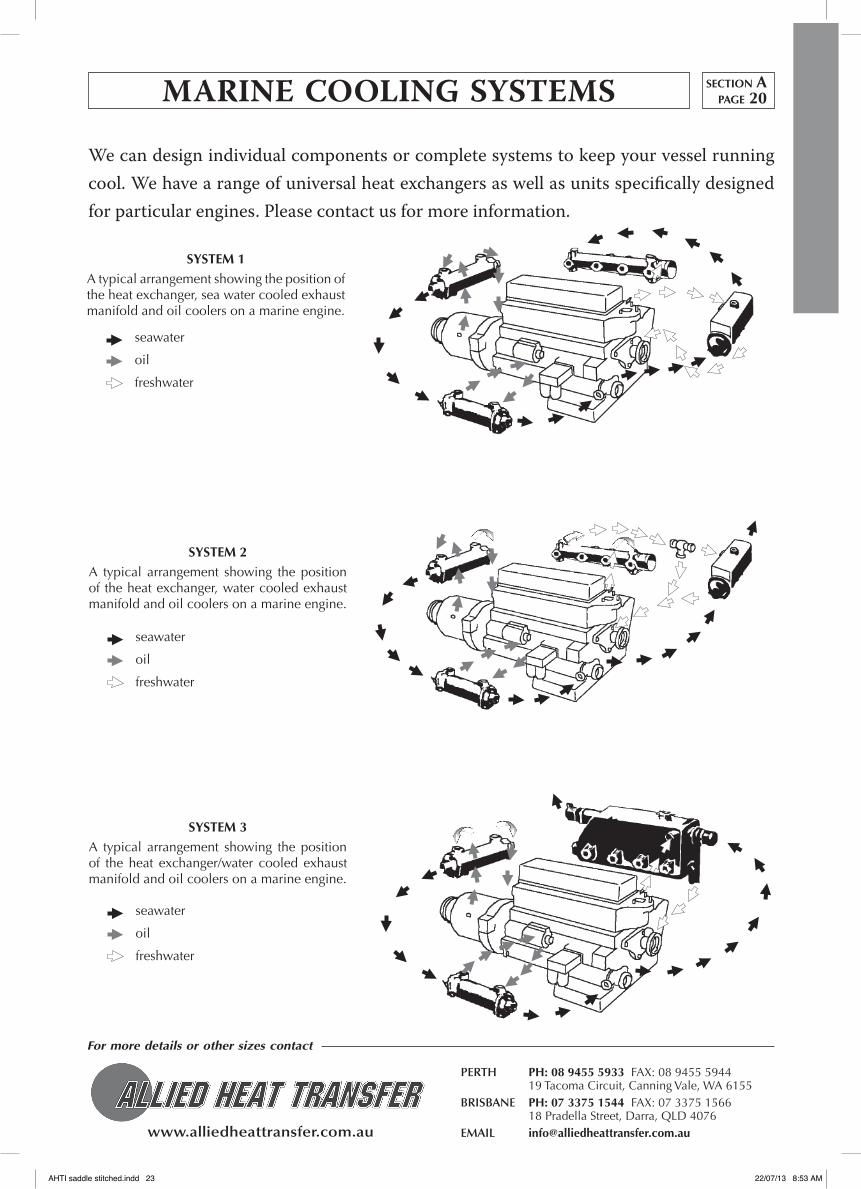
We can design individual components or complete systems to keep your vessel running cool. We have a range of universal heat exchangers as well as units specifically designed for particular engines. please contact us for more information.
MARINE COOLING SYSTEMS section Apage 20
SYSTEM 1A typical arrangement showing the position of the heat exchanger, sea water cooled exhaust manifold and oil coolers on a marine engine.
SYSTEM 2A typical arrangement showing the position of the heat exchanger, water cooled exhaust manifold and oil coolers on a marine engine.
SYSTEM 3A typical arrangement showing the position of the heat exchanger/water cooled exhaust manifold and oil coolers on a marine engine.
seawater
oil
freshwater
seawater
oil
freshwater
seawater
oil
freshwater
AHTI saddle stitched.indd 23 22/07/13 8:53 AM

www.alliedheattransfer.com.au
For more details or other sizes contact
PERTH PH: 08 9455 5933 FAX: 08 9455 5944 19 Tacoma Circuit, Canning Vale, WA 6155BRISBANE PH: 07 3375 1544 FAX: 07 3375 1566 18 Pradella Street, Darra, QLD 4076EMAIL [email protected]
These header tank heat exchangers can be used for marine engines as well as for various land-based duties such as engine testing and development work, generator sets, fire pumps and combined heat and power systems. They incorporate a quiet zone header tank and removeable tube stack which is held in position by O-rings to expand and contract freely within the cast housing, thus minimising thermal stress.
Installation
The header tank exchanger should be mounted with the header tank above the cylinder level and with the engine water circuit arranged so that it is self-venting on initial filling. A by-pass type thermostat should be used and arranged so that only the heat exchanger is by-passed when the engine is cold. All other components including a water jacketed exhaust manifold, if fitted, any oil coolers, charge air coolers and exhaust gas heat exchangers should be so positioned in the circuit so that they always receive the full flow of the engine water pump.
Thermostats of the type used on some automotive engines which simply interrupt the cooling water flow when the engine is cold, are not recommended. For unattended operation, automatic engine shut down equipment should be provided.
The range of Bowman header tank heat exchangers showing their power ratings, various water volumes and our equivalent non header tanks shell and tube units.
Maximum working raw water pressure = 15 bar
Maximum working engine water pressure = 1 bar (filler cap rating dependent)
Maximum working temperature = 110˚C
Type Typical engine suitability Raw water volume Engine Water Volume Header tank capacity Shell and tube kW HP litres litres litres heat exchanger
DH90 15 20 0.21 0.80 0.54 DC90
DH120 20 27 0.28 1.25 0.90 DC120
EH100 40 54 0.45 1.30 0.90 EC100
EH200 50 67 0.60 2.20 1.32 EC120
FH100 60 80 0.85 3.25 20.8 FC100
FH200 90 120 1.10 4.50 2.93 FC120
FH300 120 160 1.55 6.55 4.12 FG100
FH400 150 200 2.00 9.15 5.70 FG120
FH500 190 255 2.40 11.40 7.50 FG140
GH200 180 240 3.10 10.90 6.20 GL140
GH300 250 335 3.0 14.85 8.54 GL180
GH400 320 428 4.60 18.10 11.24 GL240
KH200 360 482 6.30 18.80 13.00 GK190
KH300 450 600 7.50 25.60 17.33 GK250
KH400 550 737 9.00 33.50 22.56 GK320
JH200 550 737 8.80 27.20 18.56 JK190
JH300 700 938 10.40 36.90 24.80 JK250
JH400 850 1140 12.50 46.30 32.26 JK320
PH200 950 1273 18.60 49.00 34.24 PK250
PH300 1200 1608 21.80 64.00 44.63 PK320
PH400 1400 1876 25.30 81.00 56.43 PK400
HEADER TANK HEAT EXCHANGERSsection Apage 21
AHTI saddle stitched.indd 24 22/07/13 8:53 AM

www.alliedheattransfer.com.au
For more details or other sizes contact
PERTH PH: 08 9455 5933 FAX: 08 9455 5944 19 Tacoma Circuit, Canning Vale, WA 6155BRISBANE PH: 07 3375 1544 FAX: 07 3375 1566 18 Pradella Street, Darra, QLD 4076EMAIL [email protected]
¾" BSP
55mm
94mm
engine water
inlet
30mm
170mm
55 mm
52mm
20mm
A
Filler cap rating 75KPa
raw water
inlet
engine water outlet
BC D
Counter flanges, stud bolts and gaskets are supplied for the fresh water circuit only.
Single pass Two pass
1½"BSP
M8 x 12
R22mm
52mm R10mm
raw water outlet
¾"BSP
Alternative end covers
¾"BSP
40mm
Ø30mm
WT A B C D WT A B C D
EH100 5kg 260mm 62mm 20mm 60mm EH200 6kg 346mm 105mm 60mm 60mm
1" BSP
60mm
112mm
engine water
inlet
30mm
200mm
60 mm
76mm
90mm
AFiller cap rating 75KPa
raw water
inlet
engine water outlet
B
C D
Counter flanges, stud bolts and gaskets are supplied for the fresh water circuit only.
Single pass Two pass
2"BSP
M10 x 15
R35mm
80mmR12mm
raw water outlet
1"BSP
Alternative end covers
1"BSP
50mm crs
Ø40mm
M8 x 12 Ø45mm
25mm
WT A B C D WT A B C D
FH100 8kg 358mm 100mm 45mm 95mm FH200 11kg 454mm 150mm 95mm 95mm
Engine inlet and outlet flanges have identical dimensions.
Engine inlet and outlet flanges have identical dimensions.
50mm
70 mm
HEADER TANK HEAT EXCHANGERS section Apage 22
AHTI saddle stitched.indd 25 22/07/13 8:53 AM
www.alliedheattransfer.com.au
For more details or other sizes contact
PERTH PH: 08 9455 5933 FAX: 08 9455 5944 19 Tacoma Circuit, Canning Vale, WA 6155BRISBANE PH: 07 3375 1544 FAX: 07 3375 1566 18 Pradella Street, Darra, QLD 4076EMAIL [email protected]
75mm
132mm
engine water
inlet
30mm
245mm
75 mm
76mm
32mm
AFiller cap rating 75KPa
raw water
inlet
engine water outlet
B
C D
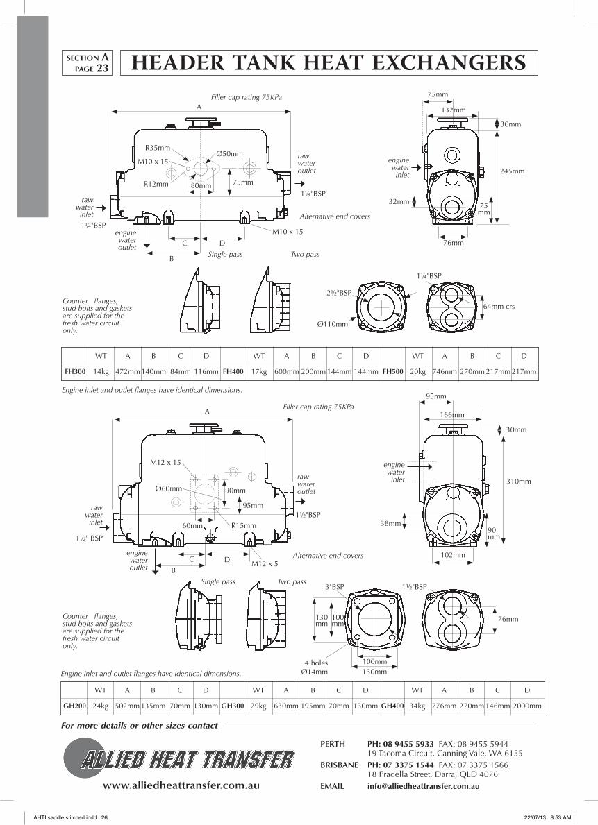
Counter flanges, stud bolts and gaskets are supplied for the fresh water circuit only.
Single pass Two pass
2½"BSP
M10 x 15
R35mm
80mm 75mm
raw water outlet
1¼"BSP
Alternative end covers
Ø110mm
64mm crs
Ø50mm
1½" BSP
95mm
166mm
engine water
inlet
30mm
310mm
90 mm
102mm
AFiller cap rating 75KPa
raw water
inlet
engine water outlet B
C D
Counter flanges, stud bolts and gaskets are supplied for the fresh water circuit only.
Single pass Two pass3"BSP
M12 x 15
60mm R15mm
raw water outlet
1½"BSP
Alternative end covers
1½"BSP
76mm
Ø60mm
M12 x 5
38mm
Engine inlet and outlet flanges have identical dimensions.
Engine inlet and outlet flanges have identical dimensions.
M10 x 151¼"BSP
R12mm
1¼"BSP
WT A B C D WT A B C D WT A B C D
FH300 14kg 472mm 140mm 84mm 116mm FH400 17kg 600mm 200mm 144mm 144mm FH500 20kg 746mm 270mm 217mm 217mm
90mm
95mm
100mm130mm
100 mm
130 mm
4 holesØ14mm
WT A B C D WT A B C D WT A B C D
GH200 24kg 502mm 135mm 70mm 130mm GH300 29kg 630mm 195mm 70mm 130mm GH400 34kg 776mm 270mm 146mm 2000mm
HEADER TANK HEAT EXCHANGERSsection Apage 23
AHTI saddle stitched.indd 26 22/07/13 8:53 AM

www.alliedheattransfer.com.au
For more details or other sizes contact
PERTH PH: 08 9455 5933 FAX: 08 9455 5944 19 Tacoma Circuit, Canning Vale, WA 6155BRISBANE PH: 07 3375 1544 FAX: 07 3375 1566 18 Pradella Street, Darra, QLD 4076EMAIL [email protected]
2" BSP
110mm194mm
engine water
inlet
30mm
120mm
AFiller cap rating 70KPa
raw water
inlet
engine water outlet
B
Counter flanges, stud bolts and gaskets are supplied for the fresh water circuit only.
Single pass Two pass
M12 x 8raw water outlet
2"BSP
Alternative end covers
2"BSP
100mmcrs
Ø100mm
M12 x 18
110mm
Engine inlet and outlet flanges have identical dimensions.
100 mm
120mm
120mm160mm
120 mm
160 mm
4 holesØ14mm
50 mm
270mm
Ø104mm
2½" BSP
130mm226mm
engine water
inlet
30mm
120mm
AFiller cap rating 70KPa
raw water
inlet
engine water outlet
B
Counter flanges, stud bolts and gaskets are supplied for the fresh water circuit only.
Single pass Two pass
M16 x 24
raw water outlet
2½"BSP
Alternative end covers
244mm
120 mm
150 mm
92mm crs
8 holesM12
60 mm
320mm
Ø76mm
Engine inlet and outlet flanges have identical dimensions.
R20mm 150 mm
92mm crs
92mm crs
150mm
120 mm
92mm crs
124mm crs
Ø130mm
Ø240mm
Ø200 mm
8 holesM12
WT A B WT A B WT A B
KH200 51kg 674mm 382mm KH300 59kg 820mm 382mm KH400 67kg 998mm 560mm
WT A B WT A B WT A B
JH200 82kg 704mm 382mm JH300 93kg 850mm 382mm JH400 106kg 1028mm 560mm
130 mm
92mm crs
92mm crs
HEADER TANK HEAT EXCHANGERS section Apage 24
AHTI saddle stitched.indd 27 22/07/13 8:53 AM

www.alliedheattransfer.com.au
For more details or other sizes contact
PERTH PH: 08 9455 5933 FAX: 08 9455 5944 19 Tacoma Circuit, Canning Vale, WA 6155BRISBANE PH: 07 3375 1544 FAX: 07 3375 1566 18 Pradella Street, Darra, QLD 4076EMAIL [email protected]
3" BSP
155mm274mm
engine water
inlet
65mm
180mm
AFiller cap rating 70KPa
raw water
inlet
engine water outlet
B
Counter flanges, stud bolts and gaskets are supplied for the fresh water circuit only.
Single pass Two pass
M16 x 24
raw water outlet
3"BSP
Alternative end covers
106mm
155 mm
150 mm
106mm crs
8 holesM16
70 mm
380mm
Ø90mm
Engine inlet and outlet flanges have identical dimensions.
R20mm180 mm 106mm
crs
106mm crs
146 mm
150mm crs
106mm
Ø150mm
Ø265mm
Ø225 mm
8 holesØ18
WT A B WT A B WT A B
PH200 136kg 890mm 382mm PH300 156kg 1078mm 560mm PH400 190kg 1280mm 762mm
150mm
M16 x 24
296mm
Ø150mm
HEADER TANK HEAT EXCHANGERSsection Apage 25
AHTI saddle stitched.indd 28 22/07/13 8:53 AM

HP Aluminium Coolers
In terms of performance, the most efficient heat transfer surface is definitely the aluminium cooler. By comparison it is the amount of surface area available that makes the aluminium cooler the most effective. However, not all aluminium coolers are the same. The HP coolers are high quality and high pressure (26 bar static/20 bar dynamic). HP coolers can be anodized for salt air applications (with prior notice) and higher-pressure ratings are available on request. HP’s come with 12 or 24 volt (smaller models), 415 volt or hydraulic motors. 240 volt can be fitted by request.
We also stock cooling systems (HPC) that come complete with their own integral circulating oil pump for easy connection to an oil tank. The HPC range has a lower pressure rating than the HP.
ST Steel Coolers
Our second ‘off the shelf’ range of coolers are the ST steel and again come complete with air plenum, fan, and motor options. The steel cooling systems are not as efficient as the aluminium so a larger system will be required to handle the same duty. The ST steel is extremely “strong” with test pressures of 100 bar. The fin on steel coolers is flat and widely spaced thereby making them easy to clean. The ST steel packages are preferred where there is potential for airside clogging or in environments where aluminium cannot be used.
The following pages list the stock range of HP, HPC and ST steel coolers along with performance information. Please remember that we make oil coolers, so if you can’t find what you need in our stock range please call us.
Contents SECTION B page
HPC Cooler with integrated oil pump 1
HP Coolers, 12/24 volt, 415 volt, hydraulic motors 2 to 9
Performance of HP Systems 10 to 17
Oil Pressure loss HP Coolers 18
Selection Guide 19 to 20
Mounting, installation HP Systems 21 to 22
ST Steel Coolers, 12/24 volt, 415 volt, hydraulic motors 23 to 33
Oil Pressure loss ST Steel Coolers 34
section BAIR/OIL COOLING SYSTEMSA
IR TO
OIL C
OO
LING
SYSTEM
S with m
oto
r, fan etc
A complete system is made up of an oil cooler panel, air plenum, fan, motor and finger guard, with options of on/off switches based on temperature, core protection guards, and so forth. Oil cooler panels are not referred to as radiators but as coolers, air/oil coolers and cooler panels. In effect they are radiators through which cooling air is moved by an electric or hydraulically driven fan.
We manufacture a number of designs ranging from copper through to stainless steel. Our main ‘off the shelf’ range are the HP aluminium and ST all steel systems.
www.alliedheattransfer.com.au
AHTI saddle stitched.indd 29 22/07/13 8:53 AM

www.alliedheattransfer.com.au
For more details or other sizes contact
PERTH PH: 08 9455 5933 FAX: 08 9455 5944 19 Tacoma Circuit, Canning Vale, WA 6155BRISBANE PH: 07 3375 1544 FAX: 07 3375 1566 18 Pradella Street, Darra, QLD 4076EMAIL [email protected]
DIMENSIONS
Model A B C D E f G H I J K* L M
HPC1/2 367 319 475 100 155 243 55.5 289 45 60 1/2" ø12 59
HPC1 468 400 495 100 200 300 56 389 45 155 1/2" 3/4" 60
HPC2 572 500 605 123 225 350 56 489 63 155 1" 11/4" 100
HPC3 672 614 630 123 225 450 56 589 63 155 1" 11/4" 100
PERfORMANCE
Cooling Oil flow Air flow Motor Noise level Pressure- Weight performance [l/min] [m3/sec] [kW/rpm] 1 m [dB(A)] bypass [kg] [kW/˚C] [bar] [bar]
HPC1/2 0.05 5.0 0.08 0.37/1370 – – 19
HPC1 0.20 15.3 0.43 0.55/1385 72 3 23
HPC2 0.48 43.1 0.82 1.1 /1400 81 3 38
HPC3 0.78 53.8 1.58 1.5 /1400 85 3 51
+-3dB(A)
D
A
L
FB M
Ø12x20 (4x)
I J
EC
H
G
HPC COOLING SYSTEM WITH INTEGRATED OIL PUMP
The HPC oil cooler with integrated oil pump functions as a separate cooling circuit which pumps the oil direct from the tank through the cooler and back to tank.
• Highefficiencycompactcooling
• Highperformancepumpwith integratedpressurebypass
Max suction height from tank to pump 2 m.
For filter connection see installation data sheet.
• Suitableforhighviscosityoilmax2000cSt
• Lownoise
• Corrosionresistant
section Bpage 1
Materials Powder Coated FinishCooler Aluminium, black RAL 9005Cowling, feet Steel, black RAL 9005Fan PPGFan guard Steel, yellow-chromated
Electric motorsVoltage 3PH 415 VSafety class Ip 55Insulation class FTemperature class B
See also data sheets on:
INSTALLATION & MAINTENANCE
SELECTION OF A COOLER OIL
PRESSURE LOSSES.
* all threads BSPP
AHTI saddle stitched.indd 30 22/07/13 8:53 AM
www.alliedheattransfer.com.au
For more details or other sizes contact
PERTH PH: 08 9455 5933 FAX: 08 9455 5944 19 Tacoma Circuit, Canning Vale, WA 6155BRISBANE PH: 07 3375 1544 FAX: 07 3375 1566 18 Pradella Street, Darra, QLD 4076EMAIL [email protected]
A F
E
B
H
H
H
G
D
C
1” (3x)ø9x12 (8)
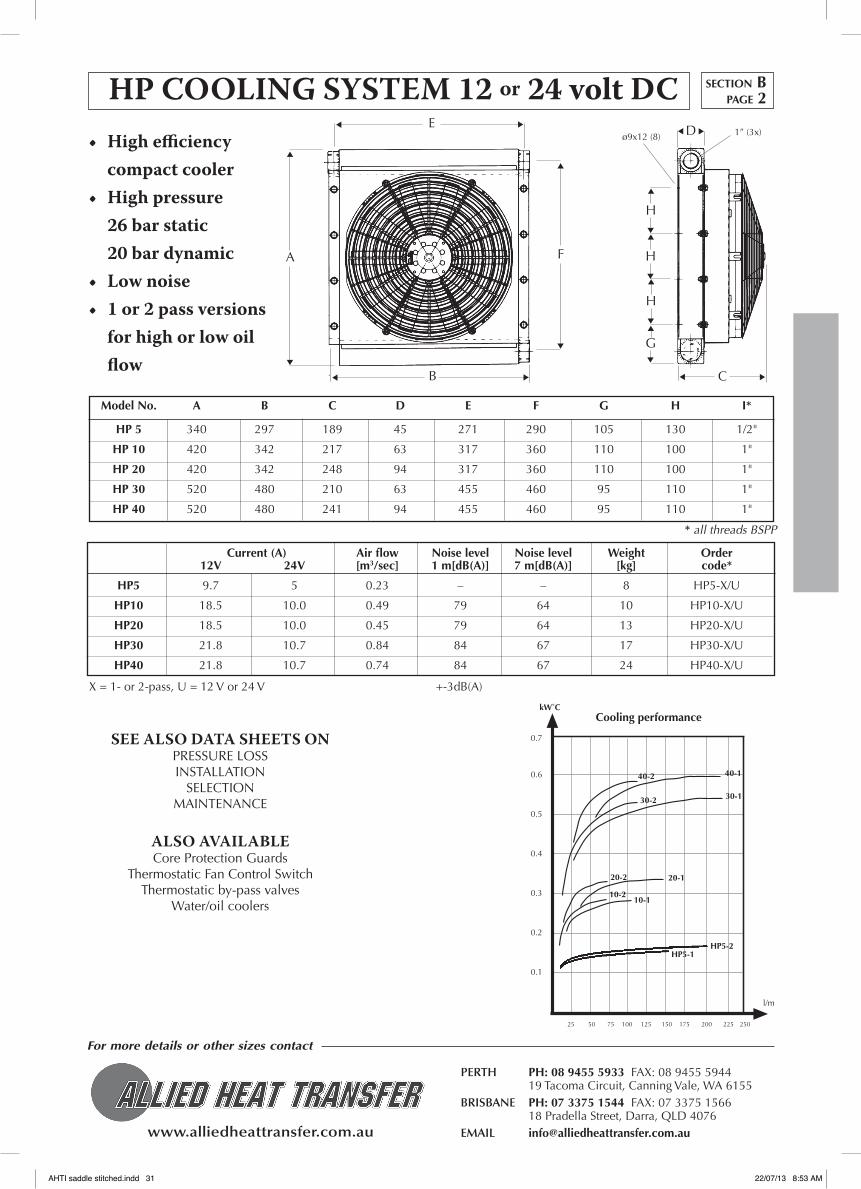
HPCOOLINGSYSTEM12or24voltDC• Highefficiency
compact cooler• Highpressure 26barstatic 20bardynamic• Lownoise• 1or2passversions
for high or low oil flow
Model No. A B C D E f G H I*
HP 5 340 297 189 45 271 290 105 130 1/2"
HP 10 420 342 217 63 317 360 110 100 1"
HP 20 420 342 248 94 317 360 110 100 1"
HP 30 520 480 210 63 455 460 95 110 1"
HP 40 520 480 241 94 455 460 95 110 1"
Current (A) Air flow Noise level Noise level Weight Order 12V 24V [m3/sec] 1 m[dB(A)] 7 m[dB(A)] [kg] code*
HP5 9.7 5 0.23 – – 8 HP5-X/U
HP10 18.5 10.0 0.49 79 64 10 HP10-X/U
HP20 18.5 10.0 0.45 79 64 13 HP20-X/U
HP30 21.8 10.7 0.84 84 67 17 HP30-X/U
HP40 21.8 10.7 0.74 84 67 24 HP40-X/U
X = 1- or 2-pass, U = 12 V or 24 V +-3dB(A)
SEE ALSO DATA SHEETS ONPRESSURE LOSSINSTALLATION
SELECTION MAINTENANCE
ALSO AVAILABLECore Protection Guards
Thermostatic Fan Control Switch Thermostatic by-pass valves
Water/oil coolers
section Bpage 2
FOR mORe inFORmatiOn OR OtheR SizeS
PLeaSe COntaCt OUR SaLeS OFFiCe
Cooling performancekW˚C
0.7
0.6
0.5
0.4
0.3
0.2
0.1
l/m
25 50 75 100 125 150 175 200 225 250
10-110-2
40-140-2
30-2 30-1
20-120-2
HP5-2HP5-1
* all threads BSPP
AHTI saddle stitched.indd 31 22/07/13 8:53 AM

www.alliedheattransfer.com.au
For more details or other sizes contact
PERTH PH: 08 9455 5933 FAX: 08 9455 5944 19 Tacoma Circuit, Canning Vale, WA 6155BRISBANE PH: 07 3375 1544 FAX: 07 3375 1566 18 Pradella Street, Darra, QLD 4076EMAIL [email protected]
HP COOLING SYSTEM 12OR24voltDCsection Bpage 3
0 50 100 150 200 250 300Oil Flow Rate (L/min)
1.0
0.9
0.8
0.7
0.6
0.5
0.4
0.3
0.2
0.1
0.0
CP
(KW / ̊ C)
• Highefficiencycompactcooler
• Highpressurerating. 26Barstatic 20Bardynamic
• Lownoise
• 1or2passversionsforhigh or low oil flow
* all threads BSPP
*X = 1- or 2-pass
U = 12V or 24V
Model No A B C D E f G H I J K*
HP50 714 661 554 225 130 374 74 610 63 154 1½"
HP60 714 661 554 256 130 405 74 610 94 154 1½"
Current (A) Air flow Noise level Noise level Weight Order
12V 24V m3/s 1m (dB(A)) 7m (dB(A)) kg code*
HP50 37 20 0.98 82 67 36 HP50-X/U
HP60 37 20 0.90 82 67 45 HP60-X/U
SEE ALSO DATA SHEETS ONPRESSURE LOSSINSTALLATIONSELECTION MAINTENANCE
ALSO AVAILABLECore Protection GuardThermostatic fan control switchThermostatic by-pass valvesWater/oil coolers
A
BC
F
H
G
D E
I J
HP60-2HP60-1
HP50-2HP50-1
K
AHTI saddle stitched.indd 32 22/07/13 8:53 AM
www.alliedheattransfer.com.au
For more details or other sizes contact
PERTH PH: 08 9455 5933 FAX: 08 9455 5944 19 Tacoma Circuit, Canning Vale, WA 6155BRISBANE PH: 07 3375 1544 FAX: 07 3375 1566 18 Pradella Street, Darra, QLD 4076EMAIL [email protected]
A
FB C
D E
I J= =
Ø12x20 (4)
K
H
G
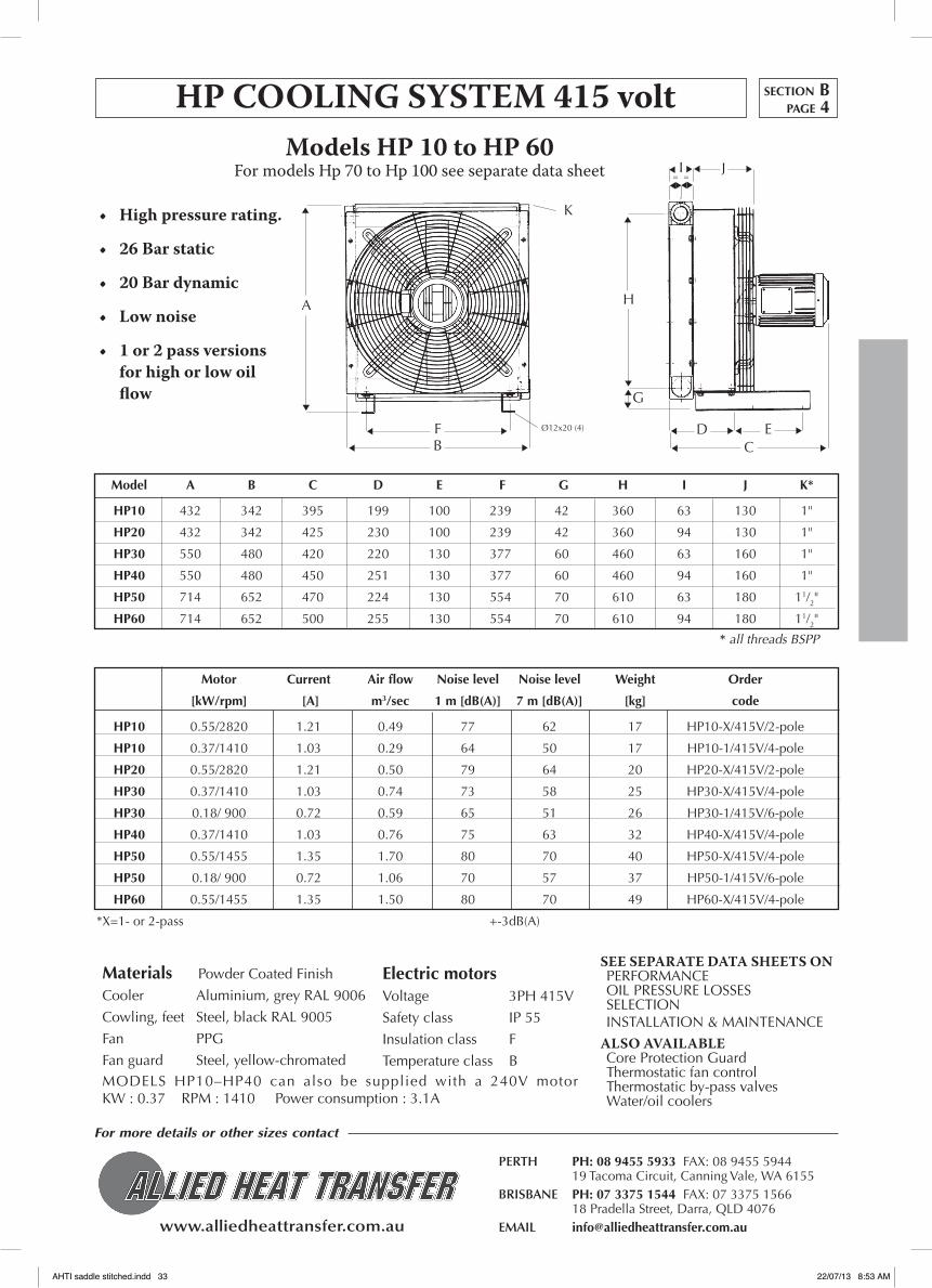
Model A B C D E f G H I J K*
HP10 432 342 395 199 100 239 42 360 63 130 1"
HP20 432 342 425 230 100 239 42 360 94 130 1"
HP30 550 480 420 220 130 377 60 460 63 160 1"
HP40 550 480 450 251 130 377 60 460 94 160 1"
HP50 714 652 470 224 130 554 70 610 63 180 11/2"
HP60 714 652 500 255 130 554 70 610 94 180 11/2"
Motor Current Air flow Noise level Noise level Weight Order
[kW/rpm] [A] m3/sec 1 m [dB(A)] 7 m [dB(A)] [kg] code
HP10 0.55/2820 1.21 0.49 77 62 17 HP10-X/415V/2-pole
HP10 0.37/1410 1.03 0.29 64 50 17 HP10-1/415V/4-pole
HP20 0.55/2820 1.21 0.50 79 64 20 HP20-X/415V/2-pole
HP30 0.37/1410 1.03 0.74 73 58 25 HP30-X/415V/4-pole
HP30 0.18/ 900 0.72 0.59 65 51 26 HP30-1/415V/6-pole
HP40 0.37/1410 1.03 0.76 75 63 32 HP40-X/415V/4-pole
HP50 0.55/1455 1.35 1.70 80 70 40 HP50-X/415V/4-pole
HP50 0.18/ 900 0.72 1.06 70 57 37 HP50-1/415V/6-pole
HP60 0.55/1455 1.35 1.50 80 70 49 HP60-X/415V/4-pole
*X=1- or 2-pass +-3dB(A)
HPCOOLINGSYSTEM415voltModelsHP10toHP60
For models Hp 70 to Hp 100 see separate data sheet
• Highpressurerating.
• 26Barstatic
• 20Bardynamic
• Lownoise
• 1or2passversionsfor high or low oil flow
Materials Powder Coated Finish
Cooler Aluminium, grey RAL 9006
Cowling, feet Steel, black RAL 9005
Fan PPG
Fan guard Steel, yellow-chromated
Electric motorsVoltage 3PH 415V
Safety class IP 55
Insulation class F
Temperature class B
SEE SEPARATE DATA SHEETS ONPERFORMANCEOIL PRESSURE LOSSESSELECTION INSTALLATION & MAINTENANCE
ALSO AVAILABLECore Protection GuardThermostatic fan controlThermostatic by-pass valvesWater/oil coolers
section Bpage 4
MODELS HP10–HP40 can also be supplied with a 240V motor KW : 0.37 RPM : 1410 Power consumption : 3.1A
* all threads BSPP
AHTI saddle stitched.indd 33 22/07/13 8:53 AM

www.alliedheattransfer.com.au
For more details or other sizes contact
PERTH PH: 08 9455 5933 FAX: 08 9455 5944 19 Tacoma Circuit, Canning Vale, WA 6155BRISBANE PH: 07 3375 1544 FAX: 07 3375 1566 18 Pradella Street, Darra, QLD 4076EMAIL [email protected]
G
A
FB C
D E
I J= =
Ø15 (4x)
K
H
Dimensions in millimetres
MODEL A B C D E f G H I J K*
HP70-1 887 784 555 119 175 759 87 760 94 225 2"
HP80-1 987 898 580 119 175 873 87 860 94 225 2"
HP90-1 1087 998 665 119 200 973 87 960 94 250 2"
HP100-1 1187 1065 665 119 200 1040 87 1060 94 250 2"
Motor Current Air flow Noise level Noise level Weight Order
[kW/rpm] [A] m3/sec 1 m [dB(A)] 7 m [dB(A)] [kg] code
HP70-1 0.75/920 2.06 2.14 77 64 91 HP70-1/415V/6-pole
HP70-1 0.37/690 1.53 1.56 69 56 91 HP70-1/415V/8-pole
HP80-1 1.1/930 3.38 3.38 79 68 111 HP80-1/415V/6-pole
HP80-1 0.55/700 2.16 2.46 72 60 111 HP80-1/415V/8-pole
HP90-1 2.2/940 6.01 4.32 85 72 137 HP90-1/415V/6-pole
HP90-1 1.1/710 3.36 3.07 76 64 131 HP90-1/415V/8-pole
HP100-1 2.2/940 6.01 5.38 84 71 157 HP100-1/415V/6pole
HP100-1 1.1/710 3.36 3.84 76 64 151 HP100-1/415V/8pole
+-3dB(A)
ModelsHP70toHP100for models Hp 10 to Hp 60 see separate data sheet
• High Efficiencycompact cooling system
• High pressurerating
• 26Barstatic• 20Bardynamic• Lownoise
Materials Powder Coated FinishCooler Aluminium, grey RAL 9006Cowling, feet Steel, black RAL 9005Fan PPG
Fan guard Steel, yellow-chromated
Electric MotorsVoltage 3PH 415VSafety class IP 55Insulation class FTemperature class B
SEE SEPARATE DATA SHEETS ONPERFORMANCEOIL PRESSURE LOSSESSELECTION INSTALLATION & MAINTENANCE
ALSO AVAILABLECore Protection GuardThermostatic fan controlThermostatic by-pass valvesWater/oil coolers
HPCOOLINGSYSTEM415voltsection Bpage 5
* all threads BSPP
AHTI saddle stitched.indd 34 22/07/13 8:53 AM

www.alliedheattransfer.com.au
For more details or other sizes contact
PERTH PH: 08 9455 5933 FAX: 08 9455 5944 19 Tacoma Circuit, Canning Vale, WA 6155BRISBANE PH: 07 3375 1544 FAX: 07 3375 1566 18 Pradella Street, Darra, QLD 4076EMAIL [email protected]
HPCOOLINGSYSTEM415voltModelsHP120andHP150
• Highefficiency
• Compactcooling
• Lownoise
• 1or2passversionsforhighor low oil flow
• Workingpressure
26barstatic 20bardynamic
section Bpage 6
Dimensions in millimetres
MODEL A B C D E f G H I J K*
HP120-1 1420 1275 889 119 266 1244 87 1260 94 351 2"
HP150-1 1715 1580 889 119 360 1548 87 1560 94 410 2"
Motor Current Air flow Noise level Noise level Weight Order
[kW/rpm] [A] m3/sec 1 m [dB(A)] 7 m [dB(A)] [kg] code
HP120-1 7.5/975 14.5 7.8 92.74 75.8 265 HP120-1/415V/6-pole
HP120-1 3/715 6.98 5.45 86 69.1 200 HP120-1/415V/8-pole
HP150-1 7.5/975 14.5 11.2 100.4 83.6 302 HP150-1/415V/6-pole
HP150-1 3/715 6.98 5.65 93.69 76.6 260 HP150-1/415V/8-pole
+-3dB(A)
* all threads BSPP
Materials Powder Coated FinishCooler Aluminium, grey RAL 9006Cowling, feet Steel, black RAL 9005Fan PPG
Fan guard Steel, yellow-chromated
Electric MotorsVoltage 3PH 415VSafety class IP 55Insulation class FTemperature class B
SEE SEPARATE DATA SHEETS ONPERFORMANCEOIL PRESSURE LOSSESSELECTION INSTALLATION & MAINTENANCE
ALSO AVAILABLECore Protection GuardThermostatic fan controlThermostatic by-pass valvesWater/oil coolers
G
A
FB C
D E
I J= =
Ø15 (4x)
K
H
AHTI saddle stitched.indd 35 22/07/13 8:53 AM

www.alliedheattransfer.com.au
For more details or other sizes contact
PERTH PH: 08 9455 5933 FAX: 08 9455 5944 19 Tacoma Circuit, Canning Vale, WA 6155BRISBANE PH: 07 3375 1544 FAX: 07 3375 1566 18 Pradella Street, Darra, QLD 4076EMAIL [email protected]
E
A
FB
C
D
I J= =
Ø12 (x20) (4)
K
H
G
Dimensions
Model A B C* D E f G H I J K* Weight [kg] Order Code
HP10 432 342 300 199 100 239 42 360 63 130 1" 17 HP10-X/HYD/Y
HP20 432 342 330 230 100 239 42 360 94 130 1" 20 HP20-X/HYD/Y
HP30 550 480 330 220 130 377 60 460 63 160 1" 26 HP30-X/HYD/Y
HP40 550 480 360 251 130 377 60 460 94 160 1" 33 HP40-X/HYD/Y
HP50 714 652 350 224 130 554 70 610 63 180 11/2" 36 HP50-X/HYD/Y
HP60 714 652 380 255 130 554 70 610 94 180 11/2" 45 HP60-X/HYD/Y
HP HYD SYSTEM WITH HYDRAULIC MOTORHPHYD10toHPHYD60
for MODELS 70 - 100 see separate data sheet
• Highefficiency
• Compactcooling
• Lownoise
• 1or2passversionsforhigh or low oil flow
• Workingpressure 26barstatic 20bardynamic
HydraulicMotorsThe following hydraulic motor
sizes can be chosen:
6, 8, 11, 16, 19 and 27 cm3/rev.
max, working pressure: 200-276
bar
Please note that the max. number
of revolutions indicated on the
graphs must not be exceeded.
See performance data sheet.
Materials Powder Coated Finish
Cooler Aluminium, grey RAL
9006
Cowling, feet Steel, black RAL 9005
fan PPG
fan guard Steel, yellow-
chromated
NoiseLevelIndicated noise level may vary + 3
dB(A). This is due to possible reflection
from surrounding items, eigenfrequen-
cies and the like. The noise measure-
ments are carried out at half spherical
spreading.
SEE SEPARATE DATA SHEETS ONPERFORMANCE
SELECTING A HP COOLING SYSTEM
OIL PRESSURE LOSSES
INSTALLATION & MAINTENANCE
OTHER MODELS
ALSO AVAILABLECore Protection Guard
Thermostatic fan control
Thermostatic by-pass valves
Water/oil coolers
* Dimension for a 27 cm3/rev hydraulic motor
X = 1 or 2 pass, Y = 6, 8, 11, 16 ,19 or 27 cm3/rev
section Bpage 7
* all threads BSPP
AHTI saddle stitched.indd 36 22/07/13 8:53 AM

www.alliedheattransfer.com.au
For more details or other sizes contact
PERTH PH: 08 9455 5933 FAX: 08 9455 5944 19 Tacoma Circuit, Canning Vale, WA 6155BRISBANE PH: 07 3375 1544 FAX: 07 3375 1566 18 Pradella Street, Darra, QLD 4076EMAIL [email protected]
A
FB C
D E
I J= =
Ø15 (4x)
K
H
G
HP HYD SYSTEM WITH HYDRAULIC MOTORHPHYD70toHPHYD100
(for MODELS 10 to 60 see separate data sheet)
• Highefficiency
• Compactcooling
• Lownoise
• Workingpressure26bar(static)
20bar(dynamic)
HydraulicmotorsThe following hydraulic motor sizes
can be chosen:
6,8,11,16,19 and 27 cm/rev.
Max working pressure: 200-276 bar
Please note that the maximum
number of revolutions indicated on
the graphs must not be exceeded.
See performance data sheet.
Dimensions
Model A B C D E f G H I J K Weight (kg) Order Code
HP70-1 887 784 480 119 175 759 87 760 94 225 2" 80 HP70-1/HYD/Y
HP80-1 987 898 480 119 175 873 87 860 94 225 2" 97 HP80-1/HYD/Y
HP90-1 1087 998 500 119 200 973 87 960 94 250 2" 113 HP90-1/HYD/Y
HP100-1 1187 1065 500 119 200 1060 87 1060 94 250 2" 133 HP100-1HYD/Y
*Dimension for a 27 cm3/rev.hydraulic motor *X = 1- or 2-pass, Y=6,8,11,16,19 or 27 cm/rev.
Materials Powder Coated Finish
Cooler Aluminium, grey RAL
9006
Cowling, feet Steel,black RAL9005
Fan PPG
Fan guard Steel, yellow-chromat-
ed
NoiselevelThe indicated noise level may vary
±3 dB(A). This is due to possible
reflection from surrounding items,
eigenfrequencies and the like. The
noise measurements are carried out
at halfspherical spreading.
SEE SEPARATE DATA SHEETS ONPERFORMANCE
SELECTING A HP COOLING SYSTEM
OIL PRESSURE LOSSES
INSTALLATION & MAINTENANCEOTHER MODELS
ALSO AVAILABLECore Protection Guard
Thermostatic fan control
Thermostatic bypass valves
Water/oil coolers
section Bpage 8
* all threads BSPP
AHTI saddle stitched.indd 37 22/07/13 8:53 AM

www.alliedheattransfer.com.au
For more details or other sizes contact
PERTH PH: 08 9455 5933 FAX: 08 9455 5944 19 Tacoma Circuit, Canning Vale, WA 6155BRISBANE PH: 07 3375 1544 FAX: 07 3375 1566 18 Pradella Street, Darra, QLD 4076EMAIL [email protected]
HP HYD SYSTEM WITH HYDRAULIC MOTORModelsHPHYD120andHYD150
• Highefficiency
• Compactcooling
• Lownoise
• 1or2passversionsfor high or low oil flow
• Workingpressure 26barstatic 20bardynamic
section Bpage 9
Dimensions in millimetres
Weight Order MODEL A B C D E f G H I J K* (kg) code
HP120-1 1420 1275 571 119 266 1244 87 1260 94 351 2" 180 HP120-1/HYD/Y
HP150-1 1715 1580 665 119 360 1548 87 1560 94 410 2" 140 HP150-1/HYD/Y
* all threads BSPP
Materials Powder Coated FinishCooler Aluminium, grey RAL 9006Cowling, feet Steel, black RAL 9005Fan PPG
Fan guard Steel, yellow-chromated
Electric MotorsVoltage 3PH 415VSafety class IP 55Insulation class FTemperature class B
SEE SEPARATE DATA SHEETS ONPERFORMANCEOIL PRESSURE LOSSESSELECTION INSTALLATION & MAINTENANCE
ALSO AVAILABLECore Protection GuardThermostatic fan controlThermostatic by-pass valvesWater/oil coolers
HydraulicmotorsThe following hydraulic motor sizes
can be chosen:
6,8,11,16,19 and 27 cm/rev.
Max working pressure: 200-276 bar
Please note that the maximum num-
ber of revolutions indicated on the
graphs must not be exceeded. See
performance data sheet.
Materials Powder Coated Finish
Cooler Aluminium, grey RAL
9006
Cowling, feet Steel,black RAL9005
Fan PPG
Fan guard Steel, yellow-chromat-
ed
NoiselevelThe indicated noise level may vary
±3 dB(A). This is due to possible
reflection from surrounding items,
eigenfrequencies and the like. The
noise measurements are carried out
at halfspherical spreading.
*Dimension for a 27 cm3/rev.hydraulic motor *X = 1- or 2-pass, Y=6,8,11,16,19 or 27 cm/rev.
A
FB C
D E
I J= =
Ø15 (4x)
K
H
G
AHTI saddle stitched.indd 38 22/07/13 8:53 AM

www.alliedheattransfer.com.au
For more details or other sizes contact
PERTH PH: 08 9455 5933 FAX: 08 9455 5944 19 Tacoma Circuit, Canning Vale, WA 6155BRISBANE PH: 07 3375 1544 FAX: 07 3375 1566 18 Pradella Street, Darra, QLD 4076EMAIL [email protected]
HP COOLING SYSTEM COOLING PERFORMANCE
ModelsHP10toHP60415V3PH
Heat rejection in kW per ˚C temperature difference between oil entering the cooler and ambient air
kW/˚C
1.3
1.2
1.1
1.0
0.9
0.8
0.7
0.6
0.5
0.4
0.3
0.2
0.1
50 100 150 200 250 300 350 400
Oil flow rate in litres per minute
Model
1 = HP60-2/415V/4-pole
2 = HP60-1/415V/4-pole
3 = HP50-2/415V/4-pole
4 = HP50-1/415V/4-pole
5 = HP50-1/415V/6-pole
6 = HP40-2/415V/4-pole
7 = HP40-1/415V/4-pole
8 = HP30-2/415V/4-poLe
9 = HP30-1/415V/4-pole
10 = HP30-1/415V/6-pole
11 = HP20-2/415V/2-pole
12 = HP20-1/415V/2-pole
13 = HP10-2/415V/2-pole
14 = HP10-1/415V/2-pole
15 = HP10-1/415V/4-pole
1
3
2
4
5
7
9
1012
14
15
6
8
11
13
SEE ALSO DATA SHEETS ONSELECTING A HP COOLER OIL PRESSURE LOSSES DIMENSIONS INSTALLATION & MAINTENANCE
PRESSURE RATING 26 BAR STATIC
20 BAR DYNAMIC
section Bpage 10
AHTI saddle stitched.indd 39 22/07/13 8:53 AM
www.alliedheattransfer.com.au
For more details or other sizes contact
PERTH PH: 08 9455 5933 FAX: 08 9455 5944 19 Tacoma Circuit, Canning Vale, WA 6155BRISBANE PH: 07 3375 1544 FAX: 07 3375 1566 18 Pradella Street, Darra, QLD 4076EMAIL [email protected]
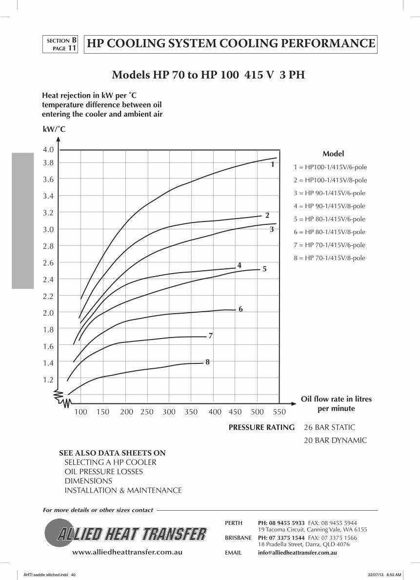
HP COOLING SYSTEM COOLING PERFORMANCE
ModelsHP70toHP100415V3PH
100 150 200 250 300 350 400 450 500 550
Model
1 = HP100-1/415V/6-pole
2 = HP100-1/415V/8-pole
3 = HP 90-1/415V/6-pole
4 = HP 90-1/415V/8-pole
5 = HP 80-1/415V/6-pole
6 = HP 80-1/415V/8-pole
7 = HP 70-1/415V/6-pole
8 = HP 70-1/415V/8-pole
1
2
3
54
8
7
6
Heat rejection in kW per ˚C temperature difference between oil entering the cooler and ambient air
Oil flow rate in litres per minute
SEE ALSO DATA SHEETS ONSELECTING A HP COOLER OIL PRESSURE LOSSES DIMENSIONS INSTALLATION & MAINTENANCE
PRESSURE RATING 26 BAR STATIC
20 BAR DYNAMIC
section Bpage 11
kW/˚C
4.0
3.8
3.6
3.4
3.2
3.0
2.8
2.6
2.4
2.2
2.0
1.8
1.6
1.4
1.2
AHTI saddle stitched.indd 40 22/07/13 8:53 AM

www.alliedheattransfer.com.au
For more details or other sizes contact
PERTH PH: 08 9455 5933 FAX: 08 9455 5944 19 Tacoma Circuit, Canning Vale, WA 6155BRISBANE PH: 07 3375 1544 FAX: 07 3375 1566 18 Pradella Street, Darra, QLD 4076EMAIL [email protected]
HP COOLING SYSTEM COOLING PERFORMANCE
ModelsHP120andHP150415V3PH
Model
1 = HP150-1/415V/6-pole
2 = HP150-1/415V/8-pole
3 = HP 120-1/415V/6-pole
4 = HP 120-1/415V/8-pole
SEE ALSO DATA SHEETS ONSELECTING A HP COOLER OIL PRESSURE LOSSES DIMENSIONS INSTALLATION & MAINTENANCE
PRESSURE RATING 26 BAR STATIC
20 BAR DYNAMIC
section Bpage 12
Heat rejection in kW per ˚C temperature difference between oil entering the cooler and ambient air
Oil flow rate in litres per minute
0 200 400 600 800
1
23
4
12
11
10
9
8
7
6
5
4
3
2
1
0
AHTI saddle stitched.indd 41 22/07/13 8:53 AM

www.alliedheattransfer.com.au
For more details or other sizes contact
PERTH PH: 08 9455 5933 FAX: 08 9455 5944 19 Tacoma Circuit, Canning Vale, WA 6155BRISBANE PH: 07 3375 1544 FAX: 07 3375 1566 18 Pradella Street, Darra, QLD 4076EMAIL [email protected]
kW/˚C
0.35
0.30
0.25
0.20
0.15
25 50 75 100 125 150 1/min
5
42
31 Motor Air flow Power Noise level MODEL [rpm] [m3/sec] kW [dB(A) 1m]
1 HP10-2 3300 0.59 0.44
2 HP10-2 2730 0.49 0.25 77
3 HP10-1 3300 0.59 0.44
4 HP10-1 2730 0.49 0.25 77
5 HP10-1 1350 0.24 0.05 64
HP 10
25 50 75 100 125 150 1/min
Motor Air flow Power Noise level MODEL [rpm] [m3/sec] kW [dB(A) 1m]
1 HP20-2 3300 0.60 0.65
2 HP20-2 2730 0.49 0.37 79
3 HP20-1 3300 0.60 0.65
4 HP20-1 2730 0.49 0.37 79
42
31
HP 20
HydraulicmotorsFollowing hydraulic motor sizes can be chosen:6, 8, 11, 16, 19 and 27 cm3/rev.Max. working pressure: 200-276 barPlease note that the max. number of revolutions indicated on the graphs must not be exceeded.
NoiselevelThe indicated noise level may vary ±3 dB(A).This is due to possible reflection from surrounding items, eigenfrequencies and the like. The noise measure-ments are carried out at halfspherical spreading.
SEE ALSO DATA SHEETS ONSELECTING A HP COOLING SYSTEMOIL PRESSURE LOSSESINSTALLATION & MAINTENANCEOTHER MODELS
HP SYSTEMS WITH HYDRAULIC MOTORCOOLING PERfORMANCE (HYDRAULIC MOTOR - continued)
kW/˚C
0.45
0.40
0.35
0.30
0.25
section Bpage 13
AHTI saddle stitched.indd 42 22/07/13 8:53 AM

www.alliedheattransfer.com.au
For more details or other sizes contact
PERTH PH: 08 9455 5933 FAX: 08 9455 5944 19 Tacoma Circuit, Canning Vale, WA 6155BRISBANE PH: 07 3375 1544 FAX: 07 3375 1566 18 Pradella Street, Darra, QLD 4076EMAIL [email protected]
COOLING PERfORMANCE (HYDRAULIC MOTOR - continued)kW/˚C
0.8
0.7
0.6
0.5
0.4
0.3
25 50 75 100 125 150 1/min
7
5
6
4
2
3
1 Motor Air flow Power Noise level MODEL [rpm] [m3/sec] kW [dB(A) 1m]
1 HP30-2 2600 1.56 1.15
2 HP30-2 2000 1.20 0.53
3 HP30-2 1350 0.74 0.16 73
4 HP30-1 2600 1.56 1.15
5 HP30-1 2000 1.20 0.53
6 HP30-1 1350 0.74 0.16 73
7 HP30-1 915 0.59 0.05 65
HP 30
25 50 75 100 125 150 175 200 225 1/min
Motor Air flow Power Noise level MODEL [rpm] [m3/sec] kW [dB(A) 1m]
1 HP40-2 2600 1.49 1.60
2 HP40-2 2000 1.14 0.72
3 HP40-2 1370 0.76 0.25 75
4 HP40-1 2600 1.49 1.60
5 HP40-1 2000 1.14 0.72
6 HP40-1 1370 0.76 0.25 75
5
6
4
2
3
1HP 40
HydraulicmotorsFollowing hydraulic motor sizes can be chosen:6, 8, 11, 16, 19 and 27 cm3/rev.Max. working pressure: 200-276 barPlease note that the max. number of revolutions indicated on the graphs must not be exceeded.
NoiselevelThe indicated noise level may vary ±3 dB(A).This is due to possible reflection from surrounding items, eigenfrequencies and the like. The noise measure-ments are carried out at halfspherical spreading.
SEE ALSO DATA SHEETS ONSELECTING A HP COOLING SYSTEMOIL PRESSURE LOSSESINSTALLATION & MAINTENANCEOTHER MODELS
kW/˚C
1.0
0.9
0.8
0.7
0.6
0.5
0.4
HP SYSTEMS WITH HYDRAULIC MOTOR section Bpage 14
AHTI saddle stitched.indd 43 22/07/13 8:53 AM

www.alliedheattransfer.com.au
For more details or other sizes contact
PERTH PH: 08 9455 5933 FAX: 08 9455 5944 19 Tacoma Circuit, Canning Vale, WA 6155BRISBANE PH: 07 3375 1544 FAX: 07 3375 1566 18 Pradella Street, Darra, QLD 4076EMAIL [email protected]
COOLING PERfORMANCE (HYDRAULIC MOTOR)
50 100 150 200 250 300 1/min
Motor Air flow Power Noise level MODEL [rpm] [m3/sec] kW [dB(A) 1m]
1 HP50-2 2000 2.46 1.50
2 HP50-2 1390 1.70 0.55 80
3 HP50-1 2000 2.46 1.50
4 HP50-1 1390 1.70 0.55 80
5 HP50-1 915 1.06 0.18 70
5
4
2
3
1
HydraulicmotorsFollowing hydraulic motor sizes can be chosen:6, 8, 11, 16, 19 and 27 cm3/rev.Max. working pressure: 200-276 barPlease note that the max. number of revolutions indicated on the graphs must not be exceeded.
NoiselevelThe indicated noise level may vary ±3 dB(A).This is due to possible reflection from surrounding items, eigenfrequencies and the like. The noise measure-ments are carried out at halfspherical spreading.
SEE ALSO DATA SHEETS ONSELECTING A HP COOLING SYSTEMOIL PRESSURE LOSSESINSTALLATION & MAINTENANCEOTHER MODELS
kW/˚c
1.4
1.3
1.2
1.1
1.0
0.9
0.8
0.7
0.6
0.5
HP 50
HP 60
kW/˚c
1.5
1.4
1.3
1.2
1.1
1.0
0.9
0.8
0.7
50 100 150 200 250 300 1/min
Motor Air flow Power Noise level MODEL [rpm] [m3/sec] kW [dB(A) 1m]
1 HP60-2 2000 2.14 1.50
2 HP60.2 1390 1.50 0.55 80
3 HP60-1 2000 2.14 1.50
4 HP60-1 1390 1.50 0.55 80
4
2
31
HP SYSTEMS WITH HYDRAULIC MOTORsection Bpage 15
AHTI saddle stitched.indd 44 22/07/13 8:53 AM

www.alliedheattransfer.com.au
For more details or other sizes contact
PERTH PH: 08 9455 5933 FAX: 08 9455 5944 19 Tacoma Circuit, Canning Vale, WA 6155BRISBANE PH: 07 3375 1544 FAX: 07 3375 1566 18 Pradella Street, Darra, QLD 4076EMAIL [email protected]
kW/˚C
3.5
3.0
2.5
2.0
1.5
1.0
100 200 300 400 500 1/min
7
5
6
42
3
1
Motor Air flow Power Noise level MODEL [rpm] [m3/sec] kW [dB(A) 1m]
1 HP80-1 1600 6.00 5.70
2 HP80-1 905 3.38 1.05 79
3 HP80-1 685 2.46 0.50 72
4 HP70-1 1800 4.20 4.60
5 HP70-1 1500 3.54 2.70
6 HP70-1 910 2.14 0.61 77
7 HP70-1 690 1.56 0.27 69
HP 70-80
100 200 300 400 500 1/min
Motor Air flow Power Noise level MODEL [rpm] [m3/sec] kW [dB(A) 1m]
1 HP100-1 1300 7.68 5.40
2 HP100-1 915 5.38 1.85 84
3 HP100-1 680 3.84 0.80 76
4 HP 90-1 1300 6.12 5.80
5 HP 90-1 915 4.03 2.10 85
6 HP 90-1 680 3.07 0.85 76
5
6
4
2
3
1 HP 90-100
HydraulicmotorsFollowing hydraulic motor sizes can be chosen:6, 8, 11, 16, 19 and 27 cm3/rev.Max. working pressure: 200-276 barPlease note that the max. number of revolutions indicated on the graphs must not be exceeded.
NoiselevelThe indicated noise level may vary ±3 dB(A).This is due to possible reflection from surrounding items, eigenfrequencies and the like. The noise measure-ments are carried out at halfspherical spreading.
SEE ALSO DATA SHEETS ONSELECTING A HP COOLING SYSTEMOIL PRESSURE LOSSESINSTALLATION & MAINTENANCEOTHER MODELS
COOLING PERfORMANCE (HYDRAULIC MOTOR - continued)
kW/˚C
5.0
4.5
4.0
3.5
3.0
2.5
2.0
HP SYSTEMS WITH HYDRAULIC MOTOR section Bpage 16
AHTI saddle stitched.indd 45 22/07/13 8:53 AM

www.alliedheattransfer.com.au
For more details or other sizes contact
PERTH PH: 08 9455 5933 FAX: 08 9455 5944 19 Tacoma Circuit, Canning Vale, WA 6155BRISBANE PH: 07 3375 1544 FAX: 07 3375 1566 18 Pradella Street, Darra, QLD 4076EMAIL [email protected]
COOLING PERfORMANCE (HYDRAULIC MOTOR - continued)
HP SYSTEMS WITH HYDRAULIC MOTORsection Bpage 17
Motor Air flow Power Noise level MODEL [rpm] [m3/sec] kW [dB(A) 1m]
1 HP150-1 960 5.78 4.5 94
2 HP150-1 760 4.4 2.5 89
3 HP120-1 960 4.3 5.0 89
4 HP120-1 760 3.25 2.5 84.7
HP120 and 150
HydraulicmotorsFollowing hydraulic motor sizes can be chosen:6, 8, 11, 16, 19 and 27 cm3/rev.Max. working pressure: 200-276 barPlease note that the max. number of revolutions indicated on the graphs must not be exceeded.
Noiselevel
The indicated noise level may vary ±3 dB(A).This is due to possible reflection from surrounding items, eigenfrequencies and the like. The noise measure-ments are carried out at halfspherical spreading.
SEE ALSO DATA SHEETS
ONSELECTING A HP COOLING SYSTEMOIL PRESSURE LOSSESINSTALLATION & MAINTENANCEOTHER MODELS
Heat rejection in kW per ˚C temperature difference between oil entering the cooler and ambient air
Oil flow rate in litres per minute
0 200 400 600 800
1
23
4
12
11
10
9
8
7
6
5
4
3
2
1
0
AHTI saddle stitched.indd 46 22/07/13 8:53 AM

www.alliedheattransfer.com.au
For more details or other sizes contact
PERTH PH: 08 9455 5933 FAX: 08 9455 5944 19 Tacoma Circuit, Canning Vale, WA 6155BRISBANE PH: 07 3375 1544 FAX: 07 3375 1566 18 Pradella Street, Darra, QLD 4076EMAIL [email protected]
HP OIL SYSTEM PRESSURE LOSS
ModelsHP5-100
Oil Pressure loss at (30cSt)∆ P(bar)
5.0
4.0
3.0
2.0
1.0
50 100 150 200 250 300 350 400 l/min
100 200 300 400 500 600 700
VISCOSITY CORRECTION CHART
10.0
8.0
6.0
4.0
2.0
Oil viscosity in cSt
Multiply result from
Pressure Loss Chart
by this factor
HP102 pass
HP30-HP50 2 pass
HP 20 2 pass
HP40-HP602 pass
HP10-HP301 pass
HP20-HP30-HP501 pass
HP40-HP60 1 passHP70-HP80 1 passHP90-HP100 1 pass
section Bpage 18
HP52 pass
HP51 pass
HP120 1 passHP150 1 pass
AHTI saddle stitched.indd 47 22/07/13 8:53 AM
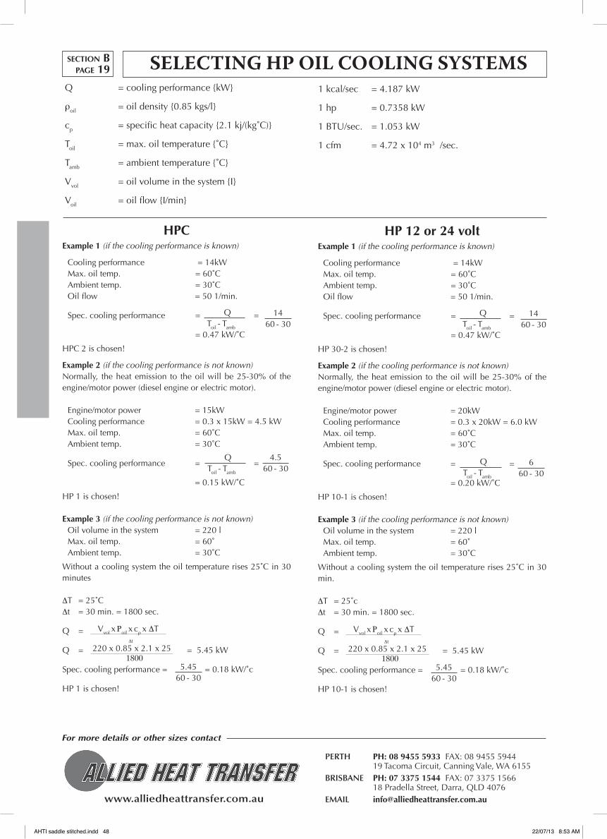
www.alliedheattransfer.com.au
For more details or other sizes contact
PERTH PH: 08 9455 5933 FAX: 08 9455 5944 19 Tacoma Circuit, Canning Vale, WA 6155BRISBANE PH: 07 3375 1544 FAX: 07 3375 1566 18 Pradella Street, Darra, QLD 4076EMAIL [email protected]
SELECTING HP OIL COOLING SYSTEMSQ = cooling performance {kW}
ρoil = oil density {0.85 kgs/l}
cp = specific heat capacity {2.1 kj/(kg˚C)}
Toil = max. oil temperature {˚C}
Tamb = ambient temperature {˚C}
Vvol = oil volume in the system {I}
Voil = oil flow {I/min}
1 kcal/sec = 4.187 kW
1 hp = 0.7358 kW
1 BTU/sec. = 1.053 kW
1 cfm = 4.72 x 10⁴ m3 /sec.
HPCExample 1 (if the cooling performance is known)
Cooling performance = 14kWMax. oil temp. = 60˚CAmbient temp. = 30˚COil flow = 50 1/min.
Spec. cooling performance = =
= 0.47 kW/˚C
HPC 2 is chosen!
Example 2 (if the cooling performance is not known) Normally, the heat emission to the oil will be 25-30% of the engine/motor power (diesel engine or electric motor).
Engine/motor power = 15kWCooling performance = 0.3 x 15kW = 4.5 kWMax. oil temp. = 60˚CAmbient temp. = 30˚C
Spec. cooling performance = =
= 0.15 kW/˚C
HP 1 is chosen!
Example 3 (if the cooling performance is not known)Oil volume in the system = 220 lMax. oil temp. = 60˚Ambient temp. = 30˚C
Without a cooling system the oil temperature rises 25˚C in 30 minutes
∆T = 25˚C∆t = 30 min. = 1800 sec.
Q =
Q = = 5.45 kW
Spec. cooling performance = = 0.18 kW/˚c
HP 1 is chosen!
QToil - Tamb
1460 - 30
QToil - Tamb
4.560 - 30
Vvol x Ρoil x cρ x ∆T ∆t
5.4560 - 30
220 x 0.85 x 2.1 x 25 1800
HP 12 or 24 voltExample 1 (if the cooling performance is known)
Cooling performance = 14kWMax. oil temp. = 60˚CAmbient temp. = 30˚COil flow = 50 1/min.
Spec. cooling performance = =
= 0.47 kW/˚C
HP 30-2 is chosen!
Example 2 (if the cooling performance is not known) Normally, the heat emission to the oil will be 25-30% of the engine/motor power (diesel engine or electric motor).
Engine/motor power = 20kWCooling performance = 0.3 x 20kW = 6.0 kWMax. oil temp. = 60˚CAmbient temp. = 30˚C
Spec. cooling performance = =
= 0.20 kW/˚C
HP 10-1 is chosen!
Example 3 (if the cooling performance is not known)Oil volume in the system = 220 lMax. oil temp. = 60˚Ambient temp. = 30˚C
Without a cooling system the oil temperature rises 25˚C in 30 min.
∆T = 25˚c∆t = 30 min. = 1800 sec.
Q =
Q = = 5.45 kW
Spec. cooling performance = = 0.18 kW/˚c
HP 10-1 is chosen!
QToil - Tamb
1460 - 30
QToil - Tamb
660 - 30
Vvol x Ρoil x cρ x ∆T ∆t
5.4560 - 30
220 x 0.85 x 2.1 x 25 1800
section Bpage 19
AHTI saddle stitched.indd 48 22/07/13 8:53 AM

www.alliedheattransfer.com.au
For more details or other sizes contact
PERTH PH: 08 9455 5933 FAX: 08 9455 5944 19 Tacoma Circuit, Canning Vale, WA 6155BRISBANE PH: 07 3375 1544 FAX: 07 3375 1566 18 Pradella Street, Darra, QLD 4076EMAIL [email protected]
SELECTING HP OIL COOLING SYSTEMSQ = cooling performance {kW}
ρoil = oil density {0.85 kgs/l}
cp = specific heat capacity {2.1 kj/(kg˚C)}
Toil = max. oil temperature {˚C}
Tamb = ambient temperature {˚C}
Vvol = oil volume in the system {I}
Voil = oil flow {I/min}
1 kcal/sec = 4.187 kW
1 hp = 0.7358 kW
1 BTU/sec. = 1.053 kW
1 cfm = 4.72 x 10⁴ m3 /sec.
HP HYDExample 1 (if the cooling performance is known)
Cooling performance = 80kWMax. oil temp. = 70˚CAmbient temp. = 30˚COil flow = 250 l/min.
Spec. cooling performance = =
= 2.00 kW/˚C
HP 70-1 (1200 rpm) or HP 80-1 (750 rpm) is chosen! The choice is dependent on possible noise limitations.
Example 2 (if the cooling performance is not known)Normally, the heat emission to the oil will be 25-30% of the engine/motor power (diesel engine or electric motor).
Engine/motor power = 30kWcooling performance = 0.3 x 30 kW = 9.0 kWMax. oil temp. = 60˚CAmbient temp. = 30˚COil flow = 35 l/min.
Spec. cooling performance = =
= 0.30 kW/˚C
HP 20-1 (2800 rpm) or HP 30-1 (900 rpm) is chosen!The choice is dependent on possible noise limitations.
Example 3 (if the cooling performance is not known)Oil volume in the system = 220 lMax. oil temp. = 60˚CAmbient temp. = 30˚COil flow = 75 l/min.
Without a cooling system the oil temperature rises 30˚C in 30 min.
∆T = 30˚C∆t = 30 min. = 1800 sec.
Q =
Q =
Spec. cooling performance = = 0.22 kW/˚C
HP 10-1 (1650 rpm) is chosen!
QToil - Tamb
8070 - 30
QToil - Tamb
960 - 30
Vvol x Ρoil x cρ x ∆T∆t
6.5560 - 30
220 x 0.85 x 2.1 x 30 1800
HP 415 voltExample 1 (if the cooling performance is known)
Cooling performance = 65kWMax. oil temp. = 70˚CAmbient temp. = 30˚COil flow = 250 l/min.
Spec. cooling performance = =
= 1.63 kW/˚C
HP 70-1/415V/6-pol or HP 80-1/415V/8-pol is chosen!The choice is dependent on possible noise limitations.
Example 2 (if the cooling performance is not known)Normally, the heat emission to the oil will be 25-30% of the engine/motor power (diesel engine or electric motor).
Engine/motor power = 30kWcooling performance = 0.3 x 30 kW = 9.0 kWMax. oil temp. = 60˚CAmbient temp. = 30˚COil flow = 35 l/min.
Spec. cooling performance = =
= 0.30 kW/˚C
HP 20-2/415V/2-pol or HP 30-1/415V/6-pol is chosen!The choice is dependent on possible noise limitations.
Example 3 (if the cooling performance is not known)Oil volume in the system = 220 lMax. oil temp. = 60˚CAmbient temp. = 30˚COil flow = 75 l/min.
Without a cooling system the oil temperature rises 30˚C in 30 minutes
∆T = 25˚C∆t = 30 min. = 1800 sec.
Q =
Q = = 5.45 kW
Spec. cooling performance = = 0.18 kW/˚C
HP 10-1/415V/4-pol is chosen!
QToil - Tamb
6570 - 30
QToil - Tamb
960 - 30
Vvol x Ρoil x cρ x ∆T∆t
5.4560 - 30
220 x 0.85 x 2.1 x 30 1800
section Bpage 20
AHTI saddle stitched.indd 49 22/07/13 8:53 AM

www.alliedheattransfer.com.au
For more details or other sizes contact
PERTH PH: 08 9455 5933 FAX: 08 9455 5944 19 Tacoma Circuit, Canning Vale, WA 6155BRISBANE PH: 07 3375 1544 FAX: 07 3375 1566 18 Pradella Street, Darra, QLD 4076EMAIL [email protected]
AA
Positioning of the coolerplease note that the cooler must be placed in a way that allows a free air flow in and out of the cooler. The minimum allowable distance to a wall is half the core height (A).
It is important that there is no recirculation of the heater air - and to ensure sufficient ventilation in the room if the cooler is mounted indoors.
Installation of the coolerA HpC oil cooler with integrated oil pump functions as a separate cooling circuit which pumps the oil direct from the tank through the cooler and back to the tank.
The circuit may also be fitted with an oil filter. The filter must, however, not be mounted direct on the oil cooler.
The suction height from tank to pump must not exceed 2 m, and the hose dimension must not be smaller than the dimension of the pump connection. The viscosity must not exceed 2000 cSt. In case of a higher viscosity, please contact the factory.
The electric motor must be connected in a way that ensures that the pump and the fan rotate in the direction indicated on the cooler and the pump.For the regulation of the oil temperature, it is recommended that a thermo-bypass or a thermo-switch is mounted.
Thermo-bypassTo be used in situations where the HpC oil cooler is used for filter circuits which require a stable oil flow. The thermo-bypass must be mounted parallel with the oil cooler.
Thermo-switchIs mounted if the HpC is used for oil cooling only. It is recommended that the thermo-switch is mounted in the oil tank for registration of the tank temperature.
MaintenanceHpC oil coolers require no special maintenance. However, if the cooler is working in very dirty surroundings, regular cleaning must be carried out. The cooling performance will be reduced if the fins are blocked due to fouling.
Cleaning of the air sideCleaning should be carried out by means of compressed air or water. In case of heavy dirt deposits, the core can be high-pressure cleaned with water. The direction of the cleaning flow must be parallel to the fins in order to avoid damage. It is recommended that the cooler is removed for cleaning, in order not to damage the electric motor.
Cleaning of the oil sideIn case of internal cleaning, the disconnected cooler can be flushed with a degreasing agent. The degreasing agent must then be blown out by means of compressed air, and the cooler must be flushed thoroughly with oil, before it is connected to the circuit again. Take care that the degreasing agent does not have a corrosive effect on aluminium.
MOUNTING INSTALLATION AND MAINTENANCE OF HPC COOLING SYSTEM
section Bpage 21
AHTI saddle stitched.indd 50 22/07/13 8:53 AM
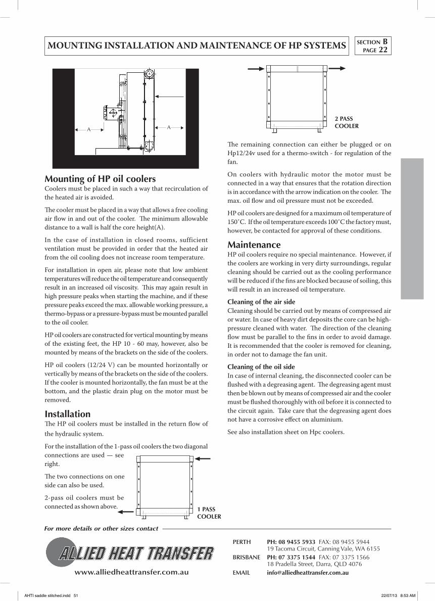
www.alliedheattransfer.com.au
For more details or other sizes contact
PERTH PH: 08 9455 5933 FAX: 08 9455 5944 19 Tacoma Circuit, Canning Vale, WA 6155BRISBANE PH: 07 3375 1544 FAX: 07 3375 1566 18 Pradella Street, Darra, QLD 4076EMAIL [email protected]
A A
Mounting of HP oil coolersCoolers must be placed in such a way that recirculation of the heated air is avoided.
The cooler must be placed in a way that allows a free cooling air flow in and out of the cooler. The minimum allowable distance to a wall is half the core height(A).
In the case of installation in closed rooms, sufficient ventilation must be provided in order that the heated air from the oil cooling does not increase room temperature.
For installation in open air, please note that low ambient temperatures will reduce the oil temperature and consequently result in an increased oil viscosity. This may again result in high pressure peaks when starting the machine, and if these pressure peaks exceed the max. allowable working pressure, a thermo-bypass or a pressure-bypass must be mounted parallel to the oil cooler.
Hp oil coolers are constructed for vertical mounting by means of the existing feet, the Hp 10 - 60 may, however, also be mounted by means of the brackets on the side of the coolers.
Hp oil coolers (12/24 v) can be mounted horizontally or vertically by means of the brackets on the side of the coolers. If the cooler is mounted horizontally, the fan must be at the bottom, and the plastic drain plug on the motor must be removed.
InstallationThe Hp oil coolers must be installed in the return flow of the hydraulic system.
For the installation of the 1-pass oil coolers the two diagonal connections are used — see right.
The two connections on one side can also be used.
2-pass oil coolers must be connected as shown above.
The remaining connection can either be plugged or on Hp12/24v used for a thermo-switch - for regulation of the fan.
On coolers with hydraulic motor the motor must be connected in a way that ensures that the rotation direction is in accordance with the arrow indication on the cooler. The max. oil flow and oil pressure must not be exceeded.
Hp oil coolers are designed for a maximum oil temperature of 150˚C. If the oil temperature exceeds 100˚C the factory must, however, be contacted for approval of these conditions.
MaintenanceHp oil coolers require no special maintenance. However, if the coolers are working in very dirty surroundings, regular cleaning should be carried out as the cooling performance will be reduced if the fins are blocked because of soiling, this will result in an increased oil temperature.
Cleaning of the air sideCleaning should be carried out by means of compressed air or water. In case of heavy dirt deposits the core can be high-pressure cleaned with water. The direction of the cleaning flow must be parallel to the fins in order to avoid damage. It is recommended that the cooler is removed for cleaning, in order not to damage the fan unit.
Cleaning of the oil sideIn case of internal cleaning, the disconnected cooler can be flushed with a degreasing agent. The degreasing agent must then be blown out by means of compressed air and the cooler must be flushed thoroughly with oil before it is connected to the circuit again. Take care that the degreasing agent does not have a corrosive effect on aluminium.
See also installation sheet on Hpc coolers.
MOUNTING INSTALLATION AND MAINTENANCE OF HP SYSTEMS
1 PASSCOOLER
2 PASSCOOLER
......
....
....
section Bpage 22
AHTI saddle stitched.indd 51 22/07/13 8:53 AM

www.alliedheattransfer.com.au
For more details or other sizes contact
PERTH PH: 08 9455 5933 FAX: 08 9455 5944 19 Tacoma Circuit, Canning Vale, WA 6155BRISBANE PH: 07 3375 1544 FAX: 07 3375 1566 18 Pradella Street, Darra, QLD 4076EMAIL [email protected]
• Heavyduty
• Allsteelcooler
• Compactcooling
• Highheattransfer
• Lownoise
• Testedat1500psi
• Easytoclean
Power consumption Air flow Noise level Noise level Weight Order
12V 24V m3/sec 1 m [dB(A)] 7 m [dB(A)] [kg] code*
ST10A 18.5 10 0.53 80 65 12 ST10A-U
* U = 12V or 24V
ST-DCCOOLINGSYSTEM 12or24voltDCST10A-12V/24V
MaterialsCooler steel blackCowling, feet Steel, black
NoiseLevelIndicated noise level may vary + 3 dB(A). This is due to possible reflection from sur-rounding items, eigenfrequencies and the like. The noise measurements are carried out at half spherical spreading.
SEE SEPARATE DATA SHEETS ONOil pressure lossesOther models
ALSO AVAILABLEThermostatic fan controlThermostatic by-pass valvesWater/oil coolers
30 50 70 90 110 130 150 170
0.110
0.040
0.050
0.060
0.070
0.080
0.090
0.100
0.120
Heat rejection in kW per ˚C temperature difference between oil entering the cooler and ambient air
Oil flow rate in litres per minute
kW/˚C Cooling performance
0.130
0.030
section Bpage 23
0-ring plug
240mm
11/16” UNO (3x)
100 mm
480mm
180mm
300mm
390mm
Ø10 x 20 slots (4)
AHTI saddle stitched.indd 52 22/07/13 8:53 AM

www.alliedheattransfer.com.au
For more details or other sizes contact
PERTH PH: 08 9455 5933 FAX: 08 9455 5944 19 Tacoma Circuit, Canning Vale, WA 6155BRISBANE PH: 07 3375 1544 FAX: 07 3375 1566 18 Pradella Street, Darra, QLD 4076EMAIL [email protected]
• Heavyduty
• Allsteelcooler
• Compactcooling
• Highheattransfer
• Lownoise
• Testedat1500psi
• Easytoclean
Power consumption Air flow Noise level Noise level Weight Order
12V 24V m3/sec 1 m [dB(A)] 7 m [dB(A)] [kg] code*
ST30A 21.8 10.7 0.93 84 67 20 ST30A-U
* U = 12V or 24V
ST-DCCOOLINGSYSTEM 12or24voltDCST30A-12V/24V
MaterialsCooler steel blackCowling, feet Steel, black
NoiseLevelIndicated noise level may vary + 3 dB(A). This is due to possible reflection from sur-rounding items, eigenfrequencies and the like. The noise measurements are carried out at half spherical spreading.
SEE SEPARATE DATA SHEETS ONOil pressure lossesOther modelsFor selection, installation and maintenance refer to HP coolers data sheets
ALSO AVAILABLEThermostatic fan controlThermostatic by-pass valvesWater/oil coolers
377mm
20 40 60 80 100 120 140 1600.050
0.100
0.150
0.200
0.250
Heat rejection in kW per ˚C temperature difference between oil entering the cooler and ambient air
Oil flow rate in litres per minute
kW/˚C Cooling performance
section Bpage 24
15/16” UNO (2)
205mm
508mm
130mm
487mm 354mm
Ø10 x 20 slots (4)
AHTI saddle stitched.indd 53 22/07/13 8:53 AM

www.alliedheattransfer.com.au
For more details or other sizes contact
PERTH PH: 08 9455 5933 FAX: 08 9455 5944 19 Tacoma Circuit, Canning Vale, WA 6155BRISBANE PH: 07 3375 1544 FAX: 07 3375 1566 18 Pradella Street, Darra, QLD 4076EMAIL [email protected]
Power consumption Air flow Noise level Noise level Weight Order 12V 24V m3/sec 1 m [dB(A)] 7 m [dB(A)] [kg] code *
ST50 37 30 0.98 89 67 36 ST50A-U
Electric motorsVoltage 3PH 415VSafety class IP 55Insulation class FTemperature class B
MaterialsCooler steel blackCowling, feet Steel, blackFan PPGFan guard Steel, yellow-chromated
NoiseLevelIndicated noise level may vary + 3 dB(A). This is due to possible reflection from sur-rounding items, eigenfrequencies and the like. The noise measurements are carried out at half spherical spreading.
SEE SEPARATE DATA SHEETS ONOil pressure lossesOther modelsFor selection, installation and maintenance refer to HP coolers data sheets
ALSO AVAILABLEThermostatic fan controlThermostatic by-pass valvesWater/oil coolers
716mm
• Heavyduty
• Allsteelcooler
• Compactcooling
• Highheattransfer
• Lownoise
• Testedat1500psi
• Easytoclean
ST-DCCOOLINGSYSTEM 12or24voltDCsection Bpage 25
675mm
554mmø10 x 20
SLOTS (4x)
274mm 100mm
15/16” UNO (2)
374mm
ST50A-12V/24V
Heat rejection in kW per ˚C temperature difference between oil entering the cooler and ambient air
0 50 100 150 200 250 300Oil flow rate in litres per minute
0.40
0.35
0.30
0.25
0.20
0.15
0.10
0.05
0
* U = 12V or 24V
AHTI saddle stitched.indd 54 22/07/13 8:53 AM
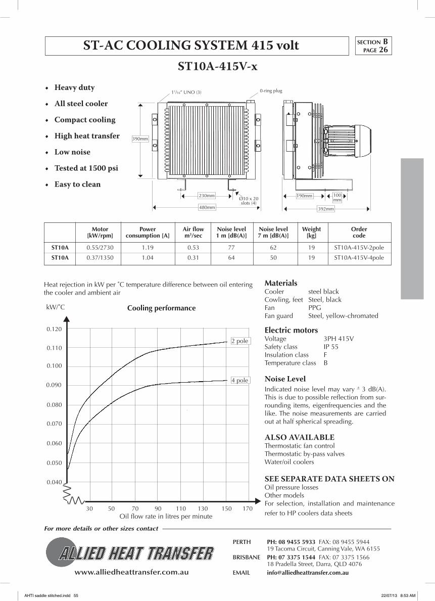
www.alliedheattransfer.com.au
For more details or other sizes contact
PERTH PH: 08 9455 5933 FAX: 08 9455 5944 19 Tacoma Circuit, Canning Vale, WA 6155BRISBANE PH: 07 3375 1544 FAX: 07 3375 1566 18 Pradella Street, Darra, QLD 4076EMAIL [email protected]
Motor Power Air flow Noise level Noise level Weight Order [kW/rpm] consumption [A] m3/sec 1 m [dB(A)] 7 m [dB(A)] [kg] code
ST10A 0.55/2730 1.19 0.53 77 62 19 ST10A-415V-2pole
ST10A 0.37/1350 1.04 0.31 64 50 19 ST10A-415V-4pole
ST-ACCOOLINGSYSTEM 415voltST10A-415V-x
Electric motorsVoltage 3PH 415VSafety class IP 55Insulation class FTemperature class B
MaterialsCooler steel blackCowling, feet Steel, blackFan PPGFan guard Steel, yellow-chromated
NoiseLevelIndicated noise level may vary + 3 dB(A). This is due to possible reflection from sur-rounding items, eigenfrequencies and the like. The noise measurements are carried out at half spherical spreading.
SEE SEPARATE DATA SHEETS ONOil pressure lossesOther modelsFor selection, installation and maintenance refer to HP coolers data sheets
ALSO AVAILABLEThermostatic fan controlThermostatic by-pass valvesWater/oil coolers
0-ring plug
30 50 70 90 110 130 150 170
0.110
0.040
0.050
0.060
0.070
0.080
0.090
0.100
0.120
2 pole
4 pole
Heat rejection in kW per ˚C temperature difference between oil entering the cooler and ambient air
Oil flow rate in litres per minute
kW/˚C Cooling performance
• Heavyduty
• Allsteelcooler
• Compactcooling
• Highheattransfer
• Lownoise
• Testedat1500psi
• Easytoclean
section Bpage 26
11/16” UNO (3)
230mm
480mm
390mm
100mm
190mm
392mm
Ø10 x 20 slots (4)
AHTI saddle stitched.indd 55 22/07/13 8:53 AM

www.alliedheattransfer.com.au
For more details or other sizes contact
PERTH PH: 08 9455 5933 FAX: 08 9455 5944 19 Tacoma Circuit, Canning Vale, WA 6155BRISBANE PH: 07 3375 1544 FAX: 07 3375 1566 18 Pradella Street, Darra, QLD 4076EMAIL [email protected]
• Heavyduty
• Allsteelcooler
• Compactcooling
• Highheattransfer
• Lownoise
• Testedat1500psi
• Easytoclean
Motor Power Air flow Noise level Noise level Weight Order
[kW/rpm] consumption [A] m3/sec 1 m [dB(A)] 7 m [dB(A)] [kg] code
ST30 0.37/1350 1.04 0.81 73 58 28 ST30A-415V-4pole
ST30 0.18/915 0.68 0.64 65 51 29 ST30A-415V-6pole
ST30A-415V-x
Electric motorsVoltage 3PH 415VSafety class IP 55Insulation class FTemperature class B
MaterialsCooler steel blackCowling, feet Steel, blackFan PPGFan guard Steel, yellow-chromated
NoiseLevelIndicated noise level may vary + 3 dB(A). This is due to possible reflection from sur-rounding items, eigenfrequencies and the like. The noise measurements are carried out at half spherical spreading.
SEE SEPARATE DATA SHEETS ONOil pressure lossesOther modelsFor selection, installation and maintenance refer to HP coolers data sheets
ALSO AVAILABLEThermostatic fan controlThermostatic by-pass valvesWater/oil coolers
20 40 60 80 100 120 140 1600.050
0.100
0.150
0.200
0.250
4 pole
6 pole
Heat rejection in kW per ˚C temperature difference between oil entering the cooler and ambient air
Oil flow rate in litres per minute
kW/˚C Cooling performance
ST-ACCOOLINGSYSTEM 415voltsection Bpage 27
15/16” UNO (2)
421mm
377mm
487mm
203mmø10 x 20 (4)
130mm
544mm
AHTI saddle stitched.indd 56 22/07/13 8:53 AM

www.alliedheattransfer.com.au
For more details or other sizes contact
PERTH PH: 08 9455 5933 FAX: 08 9455 5944 19 Tacoma Circuit, Canning Vale, WA 6155BRISBANE PH: 07 3375 1544 FAX: 07 3375 1566 18 Pradella Street, Darra, QLD 4076EMAIL [email protected]
Motor Power Air flow Noise level Noise level Weight Order
[kW/rpm] consumption [A] m3/sec 1 m [dB(A)] 7 m [dB(A)] [kg] code
ST50 0.55/1390 1.35 1.89 80 70 43 ST50-415V-4pole
ST50 0.18/915 0.7 1.17 70 57 40 ST50-415V-6pole
ST50-415V
Electric motorsVoltage 3PH 415VSafety class IP 55Insulation class FTemperature class B
MaterialsCooler steel blackCowling, feet Steel, blackFan PPGFan guard Steel, yellow-chromated
NoiseLevelIndicated noise level may vary + 3 dB(A). This is due to possible reflection from sur-rounding items, eigenfrequencies and the like. The noise measurements are carried out at half spherical spreading.
SEE SEPARATE DATA SHEETS ONOil pressure lossesOther modelsFor selection, installation and maintenance refer to HP coolers data sheets
ALSO AVAILABLEThermostatic fan controlThermostatic by-pass valvesWater/oil coolers
30 80 130 180 230 280 3200.100
0.150
0.200
0.250
0.300
0.350
0.400
4 pole
6 pole
Heat rejection in kW per ˚C temperature difference between oil entering the cooler and ambient air
Oil flow rate in litres per minute
kW/˚C Cooling performance
• Heavyduty
• Allsteelcooler
• Compactcooling
• Highheattransfer
• Lownoise
• Testedat1500psi
• Easytoclean
ST-ACCOOLINGSYSTEM 415volt section Bpage 28
716mm
675mm
554mmø10 x 20 SLOTS (4)
234mm 130mm
15/16” UNO (2)
461mm
AHTI saddle stitched.indd 57 22/07/13 8:53 AM

www.alliedheattransfer.com.au
For more details or other sizes contact
PERTH PH: 08 9455 5933 FAX: 08 9455 5944 19 Tacoma Circuit, Canning Vale, WA 6155BRISBANE PH: 07 3375 1544 FAX: 07 3375 1566 18 Pradella Street, Darra, QLD 4076EMAIL [email protected]
Motor Power Air flow Noise level Noise level Weight Order [kW/rpm] consumption [A] m3/sec 1 m [dB(A)] 7 m [dB(A)] [kg] code
ST80 1.1/930 3.38 4.04 72 55 77 ST80-415V-6pole
ST80 0.55/700 2.16 2.98 66 49 77 ST80-415V-8pole
ST80-415V
Electric motorsVoltage 3PH 415VSafety class IP 55Insulation class FTemperature class B
MaterialsCooler steel blackCowling, feet Steel, blackFan PPGFan guard Steel, yellow-chromated
NoiseLevelIndicated noise level may vary + 3 dB(A). This is due to possible reflection from surrounding items, eigenfrequen-cies and the like. The noise measure-ments are carried out at half spherical spreading.
SEE SEPARATE DATA SHEETS ONOil pressure lossesOther modelsFor selection, installation and main-tenance refer to HP coolers data sheets
ALSO AVAILABLEThermostatic fan controlThermostatic by-pass valvesWater/oil coolers
898mm
1” NPT (2)
577mm
0 50 100 150 200 250 300 3500.200
0.400
0.500
0.600
0.800
0.900
Heat rejection in kW per ˚C temperature difference between oil entering the cooler and ambient air
Oil flow rate in litres per minute
kW/˚CCooling performance
0.700
0.300
• Heavyduty
• Allsteelcooler
• Compactcooling
• Highheattransfer
• Lownoise
• Testedat1500psi
• Easytoclean
ST-ACCOOLINGSYSTEM 415voltsection Bpage 29
873mm 169mm
975mm
ø15 HOLES (4)
100mm
8 pole
6 pole
AHTI saddle stitched.indd 58 22/07/13 8:53 AM

www.alliedheattransfer.com.au
For more details or other sizes contact
PERTH PH: 08 9455 5933 FAX: 08 9455 5944 19 Tacoma Circuit, Canning Vale, WA 6155BRISBANE PH: 07 3375 1544 FAX: 07 3375 1566 18 Pradella Street, Darra, QLD 4076EMAIL [email protected]
• Heavyduty
• Allsteelcooler
• Compactcooling
• Highheattransfer
• Lownoise
• Testedat1500psi
• Easytoclean
Motor Power Air flow Noise level Noise level Weight Order
[rpm] [kW] m3/sec 1m [dB(A)] 7m [dB(A)] [kg] code
ST10A 3300 0.44 0.64 82 66 19 ST10A-HYD-Y
ST10A 2730 0.25 0.53 77 62 19 ST10A-HYD-Y
ST10A 1350 0.05 0.31 64 50 19 ST10A-HYD-Y
ST-HYDCOOLINGSYSTEM WITH HYDRAULIC MOTOR
ST10A-HYD-Y
390mm
0-ring plug
230mm
309mm
190mm
10 30 50 70 90 110 130 150 170
0.110
0.040
0.050
0.060
0.070
0.080
0.090
0.100
0.120
Heat rejection in kW per ˚C temperature difference between oil entering the cooler and ambient air
Oil flow rate in litres per minute
kW/˚CCooling performance
0.030
3300rpm
2730rpm
1350rpm
MaterialsCooler steel blackCowling, feet Steel, blackFan PPGFan guard Steel, yellow-chromated
NoiseLevelIndicated noise level may vary + 3 dB(A). This is due to possible reflection from sur-rounding items, eigenfrequencies and the like. The noise measurements are carried out at half spherical spreading.
SEE SEPARATE DATA SHEETS ONOil pressure lossesOther modelsFor selection, installation and maintenance refer to HP coolers data sheets
ALSO AVAILABLEThermostatic fan controlThermostatic by-pass valvesWater/oil coolers
HydraulicMotorsThe following hydraulic motor sizes can be chosen: 6, 8, 11, 16, 19 and 27 cm3/rev.max, working pressure: 200-276 barPlease note that the max. number of revolutions indicated on the graphs must not be exceeded.See performance data sheet.
section Bpage 30
11/16” UNO (3x)
100mm
480mm
ø10 x 20 SLOTS (4x)
AHTI saddle stitched.indd 59 22/07/13 8:53 AM

www.alliedheattransfer.com.au
For more details or other sizes contact
PERTH PH: 08 9455 5933 FAX: 08 9455 5944 19 Tacoma Circuit, Canning Vale, WA 6155BRISBANE PH: 07 3375 1544 FAX: 07 3375 1566 18 Pradella Street, Darra, QLD 4076EMAIL [email protected]
• Heavyduty
• Allsteelcooler
• Compactcooling
• Highheattransfer
• Lownoise
• Testedat1500psi
• Easytoclean
ST-HYDSYSTEM WITH HYDRAULIC MOTORST30A-HYD
10 30 50 70 90 110 130 150 170
0.110
0.040
0.050
0.060
0.070
0.080
0.090
0.100
0.120
Heat rejection in kW per ˚C temperature difference between oil entering the cooler and ambient air
Oil flow rate in litres per minute
kW/˚CCooling performance
0.030
2600rpm
2000rpm
915rpm
MaterialsCooler steel blackCowling, feet Steel, blackFan PPGFan guard Steel, yellow-chromated
NoiseLevelIndicated noise level may vary + 3 dB(A). This is due to possible reflection from sur-rounding items, eigenfrequencies and the like. The noise measurements are carried out at half spherical spreading.
SEE SEPARATE DATA SHEETS ONOil pressure lossesOther modelsFor selection, installation and maintenance refer to HP coolers data sheets
ALSO AVAILABLEThermostatic fan controlThermostatic by-pass valvesWater/oil coolers
HydraulicMotorsThe following hydraulic motor sizes can be chosen: 6, 8, 11, 16, 19 and 27 cm3/rev.max, working pressure: 200-276 barPlease note that the max. number of revolutions indicated on the graphs must not be exceeded.See performance data sheet.
Motor Power Air flow Noise level Noise level Weight Order [rpm] [kW] m3/sec 1m [dB(A)] 7m [dB(A)] [kg] code
ST30 2600 1.15 1.71 89 72 29 ST30A-HYD-Y
ST30 2000 0.53 1.31 83 67 29 ST30A-HYD-Y
ST30 1350 0.16 0.92 73 58 29 ST30A-HYD-Y
ST30 915 0.05 0.64 65 51 29 ST30A-HYD-Y
Y=6, 8, 11, 16, 19 or 27cc
1315rpm
section Bpage 31
544mm
377mm
352mm
203mm
15/16” UNO (2)
130mm
487mm
ø10 x 20 SLOTS (4x)
AHTI saddle stitched.indd 60 22/07/13 8:53 AM

www.alliedheattransfer.com.au
For more details or other sizes contact
PERTH PH: 08 9455 5933 FAX: 08 9455 5944 19 Tacoma Circuit, Canning Vale, WA 6155BRISBANE PH: 07 3375 1544 FAX: 07 3375 1566 18 Pradella Street, Darra, QLD 4076EMAIL [email protected]
Motor Power Air flow Noise level Noise level Weight Order [rpm] [kW] m3/sec 1m [dB(A)] 7m [dB(A)] [kg] code
ST50 2000 1.5 2.72 89 73 39 ST50-HYD-Y
ST50 1390 0.55 1.89 80 65 39 ST50-HYD-Y
ST50 915 0.18 1.17 70 57 39 ST50-HYD-Y
ST50-HYD
30 80 130 180 230 280 330
0.450
0.150
0.200
0.250
0.300
0.350
0.400
0.500
Heat rejection in kW per ˚C temperature difference between oil entering the cooler and ambient air
Oil flow rate in litres per minute
kW/˚CCooling performance
0.100
2000rpm
1390rpm
915rpm
MaterialsCooler steel blackCowling, feet Steel, blackFan PPGFan guard Steel, yellow-chromated
NoiseLevelIndicated noise level may vary + 3 dB(A). This is due to possible reflection from sur-rounding items, eigenfrequencies and the like. The noise measurements are carried out at half spherical spreading.
SEE SEPARATE DATA SHEETS ONOil pressure lossesOther modelsFor selection, installation and maintenance refer to HP coolers data sheets
ALSO AVAILABLEThermostatic fan controlThermostatic by-pass valvesWater/oil coolers
HydraulicMotorsThe following hydraulic motor sizes can be chosen: 6, 8, 11, 16, 19 and 27 cm3/rev.max, working pressure: 200-276 barPlease note that the max. number of revolutions indicated on the graphs must not be exceeded.See performance data sheet.
• Heavyduty
• Allsteelcooler
• Compactcooling
• Highheattransfer
• Lownoise
• Testedat1500psi
• Easytoclean
ST-HYDSYSTEM WITH HYDRAULIC MOTOR section Bpage 32
716mm
554mm
383mm
234mm
15/16” UNO (2)
130mm
675mm
ø10 x 20 SLOTS (4x)
AHTI saddle stitched.indd 61 22/07/13 8:53 AM

www.alliedheattransfer.com.au
For more details or other sizes contact
PERTH PH: 08 9455 5933 FAX: 08 9455 5944 19 Tacoma Circuit, Canning Vale, WA 6155BRISBANE PH: 07 3375 1544 FAX: 07 3375 1566 18 Pradella Street, Darra, QLD 4076EMAIL [email protected]
ST80-HYD
50 100 150 200 250 300 350
0.500
0.250
0.300
0.350
0.400
0.600
Heat rejection in kW per ˚C temperature difference between oil entering the cooler and ambient air
Oil flow rate in litres per minute
kW/˚CCooling performance
0.200
MaterialsCooler steel blackCowling, feet Steel, blackFan PPGFan guard Steel, yellow-chromated
NoiseLevelIndicated noise level may vary + 3 dB(A). This is due to possible reflection from sur-rounding items, eigenfrequencies and the like. The noise measurements are carried out at half spherical spreading.
SEE SEPARATE DATA SHEETS ONOil pressure lossesOther modelsFor selection, installation and maintenance refer to HP coolers data sheets
ALSO AVAILABLEThermostatic fan controlThermostatic by-pass valvesWater/oil coolers
HydraulicMotorsThe following hydraulic motor sizes can be chosen: 6, 8, 11, 16, 19 and 27 cm3/rev.max, working pressure: 200-276 barPlease note that the max. number of revolutions indicated on the graphs must not be exceeded.See performance data sheet.
0.450
0.550
• Heavyduty
• Allsteelcooler
• Compactcooling
• Highheattransfer
• Lownoise
• Testedat1500psi
• Easytoclean
ST-HYDSYSTEM WITH HYDRAULIC MOTORsection Bpage 33
0.650
0.700
690rpm
1800rpm
1500rpm
910rpm
Motor Power Air flow Noise level Noise level Weight Order [rpm] [kW] m3/sec 1m [dB(A)] 7m [dB(A)] [kg] code
ST80 1800 4.6 4.08 95 78 66 ST80-HYD-Y
ST80 1500 2.7 3.43 88 74 66 ST80-HYD-Y
ST80 910 0.61 2.07 77 64 66 ST80-HYD-Y
ST80 690 0.27 1.51 69 56 66 ST80-HYD-Y
Y=6, 8, 11, 16, 19 or 27cc
975mm
873mm
452mm
1” NPT (2)
169mm
898mm
ø15 HOLES (4)
100mm
AHTI saddle stitched.indd 62 22/07/13 8:53 AM

www.alliedheattransfer.com.au
For more details or other sizes contact
PERTH PH: 08 9455 5933 FAX: 08 9455 5944 19 Tacoma Circuit, Canning Vale, WA 6155BRISBANE PH: 07 3375 1544 FAX: 07 3375 1566 18 Pradella Street, Darra, QLD 4076EMAIL [email protected]
ST STEEL COOLERS PRESSURE LOSS CHARTS
ModelsST10-80
0 50 100 150 200 250 300 350 l/min
100 200 300 400 500 600 700
VISCOSITY CORRECTION CHART
10.0
8.0
6.0
4.0
2.0
Oil viscosity in cSt
Multiply result from
Pressure Loss Chart
by this factor
0.0
1.0
2.0
3.0
4.0
6.0
5.0
7.0
8.0
∆ P(bar)
9.0
Oil Pressure Loss at (30cSt)
section Bpage 34
ST 70/80
ST 50
ST 30
ST 10
AHTI saddle stitched.indd 63 22/07/13 8:53 AM

NOTES
AHTI saddle stitched.indd 64 22/07/13 8:53 AM

www.alliedheattransfer.com.au
Tf (tube fin) Coolers
These contain copper tubes and headers with aluminium plate fins. These coolers are a very cost effective option and come with rubber mounting blocks.
HE cooler
This is a highly efficient aluminium cooler panel with a maximum working pressure of 10 bar. These panels can be used in applications where there is an existing cooling air system such as in front of a radiator on a truck, ‘sandwiched’ in front of an existing cooling system, or to replace only the cooler panel from a common cooling system.
All Steel ST Coolers
These are high pressure and a very ‘strong’ cooler. Often used in applications where there is a risk of airside fin clogging. The fins are flat, widely spaced and easy to clean.
Replacement Coolers
These are a range that we have identified as common in the field. They are designed to bolt straight on with exact dimensions.
More detail on our ‘off the shelf’ range is listed in the following pages. Where possible we have nominated the performance of each cooler. Remember that performance is very much dependant on what cooling air flow is available.
If you don’t find it in the catalogue, please remember that we make, repair, rebuild and clean oil coolers, so ring us with any questions or queries.
Contents SECTION C page
TF (Tube fin) Coolers 1 to 9
HE Coolers 10
Replacement Coolers 11 to 14
ST Steel Coolers 15 to 18
Oil Pressure Loss ST Steel Coolers 19
section CC
OO
LER PA
NELS O
NLY
OIL COOLER PANELS
Oil cooler panels only, without the plenum, fan, motor, etc.
Included in the following pages are 10 bar rated aluminium coolers, 26 bar rated aluminium coolers, steel coolers, copper tube finned coolers, and a range of popular replacement coolers.
AHTI saddle stitched.indd 65 22/07/13 8:53 AM

www.alliedheattransfer.com.au
For more details or other sizes contact
PERTH PH: 08 9455 5933 FAX: 08 9455 5944 19 Tacoma Circuit, Canning Vale, WA 6155BRISBANE PH: 07 3375 1544 FAX: 07 3375 1566 18 Pradella Street, Darra, QLD 4076EMAIL [email protected]
Connection Size
Weight
2.0
1.5
1.00.90.80.70.6
0.5
0.4
0.3 2 2.5 3 3.5 4 4.5 5 7.5 10 15
Multiply HEAT
REJECTION by this factor
CORRECTION CHART for AIR VELOCITIES otherthan5M/Sec
10 20 30 40 50 60 70 80 90
HEAT REJECTED
by the COOLER
in Kw HEAT REJECTION CURVE
TEMpERATURE DIFFERENCE in ˚C between OIL ENTERING THE COOLER and AMBIENT AIR.
OIL FLOW in litres
perminute
TF OIL COOLER DATA SHEET
PART No
HEAVY DUTY COPPER TUBESHIGH EFFICIENCY ALUMINIUM FINSIN-TUBE OIL TURBULATORS
Test pressure 300psi12/24v fan available
TYPICALPERFORMANCE
Oil Flow Rate Range Heat Rejection Range
L/Min KwBased on ∆T (E.OIL–E.AIR) 55˚C and AIR V. 5 m/s
Kg
10080
60504030
20
10
54
3
2
1 10 15 20 25 30 40 75 115 150
LPM
PSIOIL PRESSURE DROP CURVE
Tf 1430
1/2" npt
1.36
10 - 45 2 - 2.5
5.0
4.5
4.0
3.5
3.0
2.5
2.0
1.5
1.0
0.5
100 cSt
10 cSt
68 cSt
45
15
30
10
38
298
204
204
215
Dimensions in millimetres
section Cpage 1
AHTI saddle stitched.indd 66 22/07/13 8:53 AM

www.alliedheattransfer.com.au
For more details or other sizes contact
PERTH PH: 08 9455 5933 FAX: 08 9455 5944 19 Tacoma Circuit, Canning Vale, WA 6155BRISBANE PH: 07 3375 1544 FAX: 07 3375 1566 18 Pradella Street, Darra, QLD 4076EMAIL [email protected]
Connection Size
Weight
2.0
1.5
1.00.90.80.70.6
0.5
0.4
0.3 2 2.5 3 3.5 4 4.5 5 7.5 10 15
Multiply HEAT
REJECTION by this factor
CORRECTION CHART for AIR VELOCITIES otherthan5M/Sec
10 20 30 40 50 60 70 80 90
HEAT REJECTED
by the COOLER
in Kw HEAT REJECTION CURVE
TEMpERATURE DIFFERENCE in ˚C between OIL ENTERING THE COOLER and AMBIENT AIR.
OIL FLOW in litres
perminute
TF OIL COOLER DATA SHEET
PART No
HEAVY DUTY COPPER TUBESHIGH EFFICIENCY ALUMINIUM FINSIN-TUBE OIL TURBULATORS
Test pressure 300psi12/24v fan available
TYPICALPERFORMANCE
Oil Flow Rate Range Heat Rejection Range
L/Min KwBased on ∆T (E.OIL–E.AIR) 55˚C and AIR V. 5 m/s
Kg
10080
60504030
20
10
54
3
2
1 10 15 20 25 30 40 75 115 150
LPM
PSIOIL PRESSURE DROP CURVE
Tf 1446
1/2" npt
1.8
10 - 45 3 - 3.85
10
9
8
7
6
5
4
3
2
1
100 cSt
10 cSt
68 cSt
45
15
25
10
38
457
362
204
228
Dimensions in millimetres
section Cpage 2
AHTI saddle stitched.indd 67 22/07/13 8:53 AM

www.alliedheattransfer.com.au
For more details or other sizes contact
PERTH PH: 08 9455 5933 FAX: 08 9455 5944 19 Tacoma Circuit, Canning Vale, WA 6155BRISBANE PH: 07 3375 1544 FAX: 07 3375 1566 18 Pradella Street, Darra, QLD 4076EMAIL [email protected]
Connection Size
Weight
2.0
1.5
1.00.90.80.70.6
0.5
0.4
0.3 2 2.5 3 3.5 4 4.5 5 7.5 10 15AIR vELOCITY at COOLER in metres/second
Multiply HEAT
REJECTION by this factor
CORRECTION CHART for AIR VELOCITIES otherthan5M/Sec
10 20 30 40 50 60 70 80 90
HEAT REJECTED
by the COOLER
in Kw HEAT REJECTION CURVE
TEMpERATURE DIFFERENCE in ˚C between OIL ENTERING THE COOLER and AMBIENT AIR.
OIL FLOW in litres
perminute
TF OIL COOLER DATA SHEET
PART No
HEAVY DUTY COPPER TUBESHIGH EFFICIENCY ALUMINIUM FINSIN-TUBE OIL TURBULATORS
Test pressure 300psi12/24v fan available
TYPICALPERFORMANCE
Oil Flow Rate Range Heat Rejection Range
L/Min KwBased on ∆T (E.OIL–E.AIR) 55˚C and AIR V. 5 m/s
Kg
10080
60504030
20
10
54
3
2
1 10 15 20 25 30 40 75 115 150
LPM
PSIOIL PRESSURE DROP CURVE
Tf 1454
3/4" npt
2.0
10 - 60 3.5 - 5.3
10
9
8
7
6
5
4
3
2
1
45
25
30
15
60
38
533
425
204
230
Dimensions in millimetres
10
100 cSt
10 cSt
68 cSt
section Cpage 3
AHTI saddle stitched.indd 68 22/07/13 8:53 AM

www.alliedheattransfer.com.au
For more details or other sizes contact
PERTH PH: 08 9455 5933 FAX: 08 9455 5944 19 Tacoma Circuit, Canning Vale, WA 6155BRISBANE PH: 07 3375 1544 FAX: 07 3375 1566 18 Pradella Street, Darra, QLD 4076EMAIL [email protected]
Connection Size
Weight
2.0
1.5
1.00.90.80.70.6
0.5
0.4
0.3 2 2.5 3 3.5 4 4.5 5 7.5 10 15AIR vELOCITY at COOLER in metres/second
Multiply HEAT
REJECTION by this factor
CORRECTION CHART for AIR VELOCITIES otherthan5M/Sec
10 20 30 40 50 60 70 80 90
HEAT REJECTED
by the COOLER
in Kw HEAT REJECTION CURVE
TEMpERATURE DIFFERENCE in ˚C between OIL ENTERING THE COOLER and AMBIENT AIR.
OIL FLOW in litres
perminute
TF OIL COOLER DATA SHEET
PART No
HEAVY DUTY COPPER TUBESHIGH EFFICIENCY ALUMINIUM FINSIN-TUBE OIL TURBULATORS
Test pressure 300psi12/24v fan available
TYPICALPERFORMANCE
Oil Flow Rate Range Heat Rejection Range
L/Min KwBased on ∆T (E.OIL–E.AIR) 55˚C and AIR V. 5 m/s
Kg
10080
60504030
20
10
54
3
2
1 10 15 20 25 30 40 75 115 150
LPM
PSIOIL PRESSURE DROP CURVE
Tf 1645
3.0
15 - 90 4.7 - 6.2
10
9
8
7
6
5
4
3
2
1
100 cSt
10 cSt
68 cSt
30
15
45
90
60
38
457
336
305
338
Dimensions in millimetres
section Cpage 4
3/4" npt
AHTI saddle stitched.indd 69 22/07/13 8:53 AM
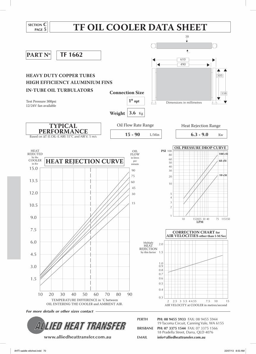
www.alliedheattransfer.com.au
For more details or other sizes contact
PERTH PH: 08 9455 5933 FAX: 08 9455 5944 19 Tacoma Circuit, Canning Vale, WA 6155BRISBANE PH: 07 3375 1544 FAX: 07 3375 1566 18 Pradella Street, Darra, QLD 4076EMAIL [email protected]
Connection Size
Weight
2.0
1.5
1.00.90.80.70.6
0.5
0.4
0.3 2 2.5 3 3.5 4 4.5 5 7.5 10 15AIR vELOCITY at COOLER in metres/second
Multiply HEAT
REJECTION by this factor
CORRECTION CHART for AIR VELOCITIES otherthan5M/Sec
10 20 30 40 50 60 70 80 90
HEAT REJECTED
by the COOLER
in Kw HEAT REJECTION CURVE
TEMpERATURE DIFFERENCE in ˚C between OIL ENTERING THE COOLER and AMBIENT AIR.
OIL FLOW in litres
perminute
TF OIL COOLER DATA SHEET
PART No
HEAVY DUTY COPPER TUBESHIGH EFFICIENCY ALUMINIUM FINSIN-TUBE OIL TURBULATORS
Test pressure 300psi12/24v fan available
TYPICALPERFORMANCE
Oil Flow Rate Range Heat Rejection Range
L/Min KwBased on ∆T (E.OIL–E.AIR) 55˚C and AIR V. 5 m/s
Kg
10080
60504030
20
10
54
3
2
1 10 15 20 25 30 40 75 115 150
LPM
PSIOIL PRESSURE DROP CURVE
Tf 1662
1" npt
3.6
15 - 90 6.3 - 9.0
15.0
13.5
12.0
10.5
9.0
7.5
6.0
4.5
3.0
1.5
100 cSt
10 cSt
68 cSt
30
15
45
90
60
75
38
610
490
305
338
Dimensions in millimetres
section Cpage 5
AHTI saddle stitched.indd 70 22/07/13 8:53 AM
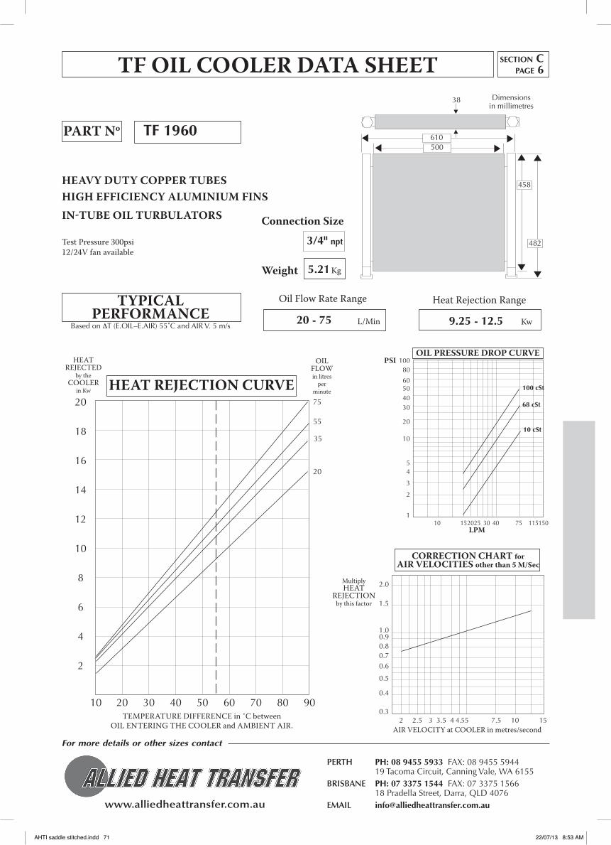
www.alliedheattransfer.com.au
For more details or other sizes contact
PERTH PH: 08 9455 5933 FAX: 08 9455 5944 19 Tacoma Circuit, Canning Vale, WA 6155BRISBANE PH: 07 3375 1544 FAX: 07 3375 1566 18 Pradella Street, Darra, QLD 4076EMAIL [email protected]
Connection Size
Weight
10 20 30 40 50 60 70 80 90
HEAT REJECTED
by the COOLER
in Kw HEAT REJECTION CURVE
TEMpERATURE DIFFERENCE in ˚C between OIL ENTERING THE COOLER and AMBIENT AIR.
OIL FLOW in litres
perminute
TF OIL COOLER DATA SHEET
PART No
HEAVY DUTY COPPER TUBESHIGH EFFICIENCY ALUMINIUM FINSIN-TUBE OIL TURBULATORS
Test pressure 300psi12/24v fan available
TYPICALPERFORMANCE
Oil Flow Rate Range Heat Rejection Range
L/Min KwBased on ∆T (E.OIL–E.AIR) 55˚C and AIR V. 5 m/s
Kg
2.0
1.5
1.00.90.80.70.6
0.5
0.4
0.3 2 2.5 3 3.5 4 4.5 5 7.5 10 15AIR vELOCITY at COOLER in metres/second
Multiply HEAT
REJECTION by this factor
CORRECTION CHART for AIR VELOCITIES otherthan5M/Sec
Tf 1960
3/4" npt
5.21
20 - 75 9.25 - 12.5
20
18
16
14
12
10
8
6
4
2
10080
60504030
20
10
54
3
2
1 10 15 20 25 30 40 75 115 150
LPM
PSIOIL PRESSURE DROP CURVE
100 cSt
10 cSt
68 cSt
20
35
55
75
610500
458
482
Dimensions in millimetres
38
section Cpage 6
AHTI saddle stitched.indd 71 22/07/13 8:53 AM

www.alliedheattransfer.com.au
For more details or other sizes contact
PERTH PH: 08 9455 5933 FAX: 08 9455 5944 19 Tacoma Circuit, Canning Vale, WA 6155BRISBANE PH: 07 3375 1544 FAX: 07 3375 1566 18 Pradella Street, Darra, QLD 4076EMAIL [email protected]
Connection Size
Weight
2.0
1.5
1.00.90.80.70.6
0.5
0.4
0.3 2 2.5 3 3.5 4 4.5 5 7.5 10 15AIR vELOCITY at COOLER in metres/second
Multiply HEAT
REJECTION by this factor
CORRECTION CHART for AIR VELOCITIES otherthan5M/Sec
10 20 30 40 50 60 70 80 90
HEAT REJECTED
by the COOLER
in Kw HEAT REJECTION CURVE
TEMpERATURE DIFFERENCE in ˚C between OIL ENTERING THE COOLER and AMBIENT AIR.
OIL FLOW in litres
perminute
TF OIL COOLER DATA SHEET
PART No
HEAVY DUTY COPPER TUBESHIGH EFFICIENCY ALUMINIUM FINSIN-TUBE OIL TURBULATORS
Test pressure 300psi12/24v fan available
TYPICALPERFORMANCE
Oil Flow Rate Range Heat Rejection Range
L/Min KwBased on ∆T (E.OIL–E.AIR) 55˚C and AIR V. 5 m/s
Kg
10080
60504030
20
10
54
3
2
1 10 15 20 25 30 40 75 115 150
LPM
PSIOIL PRESSURE DROP CURVE
Tf 11260
1" npt
7.0
20 - 120 11.5 - 16.5
25.0
22.5
20.0
17.5
15.0
12.5
10.0
7.5
5.0
2.5
100 cSt
10 cSt
68 cSt
20
40
120
80
610490
610
642
Dimensions in millimetres
38
section Cpage 7
AHTI saddle stitched.indd 72 22/07/13 8:53 AM

www.alliedheattransfer.com.au
For more details or other sizes contact
PERTH PH: 08 9455 5933 FAX: 08 9455 5944 19 Tacoma Circuit, Canning Vale, WA 6155BRISBANE PH: 07 3375 1544 FAX: 07 3375 1566 18 Pradella Street, Darra, QLD 4076EMAIL [email protected]
Connection Size
Weight
2.0
1.5
1.00.90.80.70.6
0.5
0.4
0.3 2 2.5 3 3.5 4 4.5 5 7.5 10 15AIR vELOCITY at COOLER in metres/second
Multiply HEAT
REJECTION by this factor
CORRECTION CHART for AIR VELOCITIES otherthan5M/Sec
10 20 30 40 50 60 70 80 90
HEAT REJECTED
by the COOLER
in Kw HEAT REJECTION CURVE
TEMpERATURE DIFFERENCE in ˚C between OIL ENTERING THE COOLER and AMBIENT AIR.
OIL FLOW in litres
perminute
TF OIL COOLER DATA SHEET
PART No
HEAVY DUTY COPPER TUBESHIGH EFFICIENCY ALUMINIUM FINSIN-TUBE OIL TURBULATORS
Test pressure 300psi12/24v fan available
TYPICALPERFORMANCE
Oil Flow Rate Range Heat Rejection Range
L/Min KwBased on ∆T (E.OIL–E.AIR) 55˚C and AIR V. 5 m/s
Kg
10080
60504030
20
10
54
3
2
1 10 15 20 25 30 40 75 115 150
LPM
PSIOIL PRESSURE DROP CURVE
Tf 11561
11/4" npt
9.5
25 - 200 15.0 - 22.0
50
45
40
35
30
25
20
15
10
5
25
50
200
150
100
1008060504030
20
10
543
2
110 15 20 25 40 75 115 150 225 300 375
LPM
PSI 100 cSt
10 cSt
68 cSt
610475
762
800
Dimensions in millimetres
38
section Cpage 8
OIL PRESSURE DROP CURVE
AHTI saddle stitched.indd 73 22/07/13 8:53 AM

www.alliedheattransfer.com.au
For more details or other sizes contact
PERTH PH: 08 9455 5933 FAX: 08 9455 5944 19 Tacoma Circuit, Canning Vale, WA 6155BRISBANE PH: 07 3375 1544 FAX: 07 3375 1566 18 Pradella Street, Darra, QLD 4076EMAIL [email protected]
Connection Size
Weight
2.0
1.5
1.00.90.80.70.6
0.5
0.4
0.3 2 2.5 3 3.5 4 4.5 5 7.5 10 15
Multiply HEAT
REJECTION by this factor
CORRECTION CHART for AIR VELOCITIES otherthan5M/Sec
5 15 25 35 45 55 65
HEAT REJECTED
by the COOLER
in Kw
HEAT REJECTION CURVE
TEMpERATURE DIFFERENCE in ˚C between OIL ENTERING THE COOLER and AMBIENT AIR.
OIL FLOW in litres
perminute
TF OIL COOLER DATA SHEET
PART No
HEAVY DUTY COPPER TUBESHIGH EFFICIENCY ALUMINIUM FINSIN-TUBE OIL TURBULATORS
Test pressure 300psi12/24v fan available
TYPICALPERFORMANCE
Oil Flow Rate Range Heat Rejection Range
L/Min KwBased on ∆T (E.OIL–E.AIR) 55˚C and AIR V. 5 m/s
Kg
Tf 11577
1" npt
10.9
19 - 114 6.0 - 33.0
45
40
35
30
25
20
15
10
5
0
LPM
PSI OIL PRESSURE DROP CURVE
100 cSt
10 cSt
68 cSt
38
19
57
114
7695
38
762
641
762
795
Dimensions in millimetres
section Cpage 9
60
50
40
30
20
10
020 40 60 80 100 120 140
AHTI saddle stitched.indd 74 22/07/13 8:53 AM
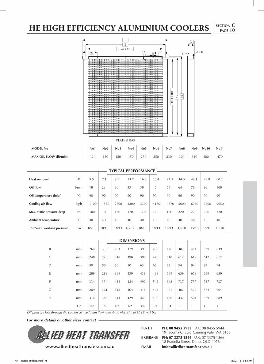
www.alliedheattransfer.com.au
For more details or other sizes contact
PERTH PH: 08 9455 5933 FAX: 08 9455 5944 19 Tacoma Circuit, Canning Vale, WA 6155BRISBANE PH: 07 3375 1544 FAX: 07 3375 1566 18 Pradella Street, Darra, QLD 4076EMAIL [email protected]
MODEL No No1 No2 No3 No4 No5 No6 No7 No8 No9 No10 No11
MAX OIL fLOW (lit/min) 120 150 150 150 250 250 230 300 330 400 470
TYPICAL PERfORMANCE
Heat removed kW 5.5 7.1 9.9 13.7 16.0 20.4 24.5 34.0 42.1 49.8 60.2
Oil flow l/min 18 23 30 33 38 45 54 64 78 90 108
Oil temperature (inlet) ˚C 90 90 90 90 90 90 90 90 90 90 90
Cooling air flow kg/h 1100 1550 2600 3800 3300 4180 4870 5600 6750 7900 9650
Max. static pressure drop Pa 100 100 170 170 170 170 170 220 220 220 220
Ambient temperature ˚C 40 40 40 40 40 40 40 40 40 40 40
Test/max. working pressure bar 18/13 18/13 18/13 18/13 18/13 18/13 18/13 15/10 15/10 15/10 15/10
DIMENSIONS
B mm 264 336 293 379 393 450 436 382 454 539 639
C mm 248 248 348 398 398 448 548 612 612 612 612
D mm 50 50 50 50 63 63 63 94 94 94 94
E mm 289 289 389 439 439 489 589 659 659 659 659
F mm 334 334 434 484 492 542 642 737 737 737 737
G mm 289 361 318 404 418 475 461 407 479 564 664
H mm 314 386 343 429 443 500 486 432 504 589 689
I GII 1/2 1/2 1/2 1/2 3/4 3/4 3/4 1 1 1 1
HE HIGH EFFICIENCY ALUMINIUM COOLERS
Oil pressure loss through the coolers at maximum flow rates @ oil viscosity of 30 cSt = 3 bar
section Cpage 10
70C=CORE
EF
709
12 3I (x3)
D
PLATE & BAR
B=
CO
RE
HG
AHTI saddle stitched.indd 75 22/07/13 8:53 AM

www.alliedheattransfer.com.au
For more details or other sizes contact
PERTH PH: 08 9455 5933 FAX: 08 9455 5944 19 Tacoma Circuit, Canning Vale, WA 6155BRISBANE PH: 07 3375 1544 FAX: 07 3375 1566 18 Pradella Street, Darra, QLD 4076EMAIL [email protected]
REPLACEMENT OIL COOLERS
The cooler brazing process takes place in a temperature controlled nitrogen
atmosphere furnace. Coolers brazed using this new fluxless system do
not require any flushing or post-brazing treatment and do not suffer from
internal flux corrosion.
section Cpage 11
PORTS AREA VOL BSPP m2 litres
1” .065 1.17
AHTI 19
• Aonepiecebrazedaluminium cooler
• Veryhighefficiency
• Superiorcorrosionresistance
• Improvedworkingpressureratingto250psi
• Ruggedanddurable
THE HEAVY DUTY VERSIONTESTED TO OvER 300psi
296 mm
322 mm
20mm
63.5 mm
203 mm
370 mm
63.5 mm
8x11 x 16
½" BSPP 2X 1" BSPP
63mm
100 mm 51
mm
107 mm Dimensions in millimetres
AHTI saddle stitched.indd 76 22/07/13 8:53 AM
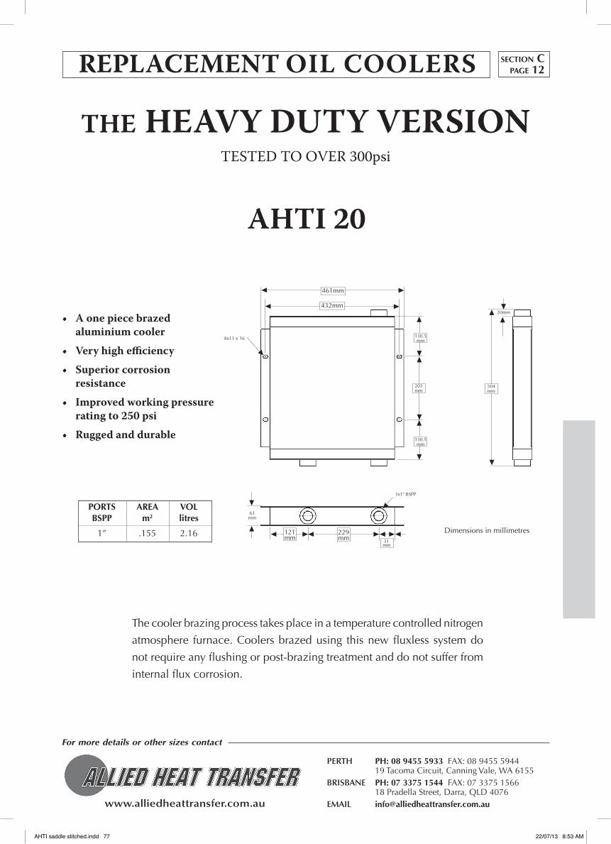
www.alliedheattransfer.com.au
For more details or other sizes contact
PERTH PH: 08 9455 5933 FAX: 08 9455 5944 19 Tacoma Circuit, Canning Vale, WA 6155BRISBANE PH: 07 3375 1544 FAX: 07 3375 1566 18 Pradella Street, Darra, QLD 4076EMAIL [email protected]
REPLACEMENT OIL COOLERS
• Aonepiecebrazedaluminium cooler
• Veryhighefficiency
• Superiorcorrosionresistance
• Improvedworkingpressureratingto250psi
• Ruggedanddurable
The cooler brazing process takes place in a temperature controlled nitrogen
atmosphere furnace. Coolers brazed using this new fluxless system do
not require any flushing or post-brazing treatment and do not suffer from
internal flux corrosion.
section Cpage 12
PORTS AREA VOL BSPP m2 litres
1” .155 2.16
AHTI20
THE HEAVY DUTY VERSIONTESTED TO OvER 300psi
Dimensions in millimetres
130.5 mm
20mm
121 mm
51 mm
229 mm
203 mm
504 mm
130.5 mm
8x11 x 16
3x1" BSPP
63mm
432mm
461mm
AHTI saddle stitched.indd 77 22/07/13 8:53 AM

www.alliedheattransfer.com.au
For more details or other sizes contact
PERTH PH: 08 9455 5933 FAX: 08 9455 5944 19 Tacoma Circuit, Canning Vale, WA 6155BRISBANE PH: 07 3375 1544 FAX: 07 3375 1566 18 Pradella Street, Darra, QLD 4076EMAIL [email protected]
REPLACEMENT OIL COOLERS
The cooler brazing process takes place in a temperature controlled nitrogen
atmosphere furnace. Coolers brazed using this new fluxless system do
not require any flushing or post-brazing treatment and do not suffer from
internal flux corrosion.
section Cpage 13
PORTS AREA VOL BSPP m2 litres
11/4” .329 3.82
AHTI21
• Aonepiecebrazedaluminium cooler
• Veryhighefficiency
• Superiorcorrosionresistance
• Improvedworkingpressureratingto250psi
• Ruggedanddurable
THE HEAVY DUTY VERSIONTESTED TO OvER 300psi
25mm
140 mm
81mm
129 mm 51
mm
406 mm
685 mm193
mm
140 mm
Dimensions in millimetres
63mm
16x11 x 16
81mm
3x1¼" BSPP
646mm
622mm
AHTI saddle stitched.indd 78 22/07/13 8:53 AM

www.alliedheattransfer.com.au
For more details or other sizes contact
PERTH PH: 08 9455 5933 FAX: 08 9455 5944 19 Tacoma Circuit, Canning Vale, WA 6155BRISBANE PH: 07 3375 1544 FAX: 07 3375 1566 18 Pradella Street, Darra, QLD 4076EMAIL [email protected]
REPLACEMENT OIL COOLERS
The cooler brazing process takes place in a temperature controlled nitrogen
atmosphere furnace. Coolers brazed using this new fluxless system do
not require any flushing or post-brazing treatment and do not suffer from
internal flux corrosion.
section Cpage 14
PORTS AREA VOL BSPP m2 litres
11/4” .560 5.80
AHTI22
• Aonepiecebrazedaluminium cooler
• Veryhighefficiency
• Superiorcorrosionresistance
• Improvedworkingpressure rating to 250psi
• Ruggedanddurable
THE HEAVY DUTY VERSIONTESTED TO OvER 300psi
Dimensions in millimetres
25mm
147 mm
152mm
231 mm
51 mm
484 mm
851 mm203
mm
147 mm
94mm
16x11 x 16
3x1¼" BSPP
152mm
800mm
823mm
AHTI saddle stitched.indd 79 22/07/13 8:53 AM

www.alliedheattransfer.com.au
For more details or other sizes contact
PERTH PH: 08 9455 5933 FAX: 08 9455 5944 19 Tacoma Circuit, Canning Vale, WA 6155BRISBANE PH: 07 3375 1544 FAX: 07 3375 1566 18 Pradella Street, Darra, QLD 4076EMAIL [email protected]
STEEL OIL COOLERS• Heavy Duty • aLL SteeL • MaXIMuM StReNGtH • HIGH Heat tRaNSFeR• eaSy tO CLeaN • teSteD tO 1500 pSI • CaN Be paCKaGeD WItH FaN aND MOtOR
Oil flow rate range
PART No
Heat rejection range
Max.workingpressure
Weight
Connection size
Heat rejection in kW per ˚C temperature difference between oil entering the cooler and ambient air
0 50 100 150 200 250 300 350 4000.030
Oil flow rate in litres per minute
kW/˚C
EXAMPLE: With an oil flow at 200 l/min, oil temperature in at 80˚C and ambient air at 40˚C, with 6m/s of cooling air, from the graph the cooler will dissipate approximately 0.117kW/˚C which gives a heat dissipation of:
0.57kW/˚C x (80-40) = 4.68kW
ST 10A
8.5 kg
11/16"
10-140 l/min
2-7 kW
500 psi
0.050
0.070
0.090
0.110
0.130
0.150
0.170
305mm
331mm
458mm
116mm
342mm
50mm
COOLING PERfORMANCE
Performance curves at a given air velocity
388mmUNO
11/16” UNO (3x)
O-ring plug
12m/s10m/s
8m/s
6m/s
4m/s
2m/s
section Cpage 15
For this cooler in a complete package with fan and motor assembly, see data sheets on part numbers ST10A-AC, ST10A-HYD, ST10A-AC and ST10A-HYD in this catalogue.
AHTI saddle stitched.indd 80 22/07/13 8:53 AM
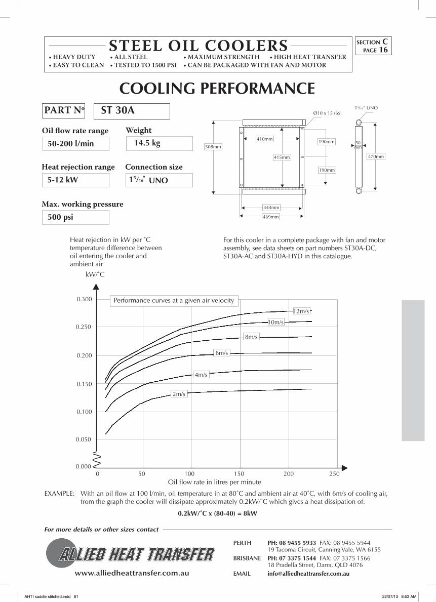
www.alliedheattransfer.com.au
For more details or other sizes contact
PERTH PH: 08 9455 5933 FAX: 08 9455 5944 19 Tacoma Circuit, Canning Vale, WA 6155BRISBANE PH: 07 3375 1544 FAX: 07 3375 1566 18 Pradella Street, Darra, QLD 4076EMAIL [email protected]
STEEL OIL COOLERS• Heavy Duty • aLL SteeL • MaXIMuM StReNGtH • HIGH Heat tRaNSFeR• eaSy tO CLeaN • teSteD tO 1500 pSI • CaN Be paCKaGeD WItH FaN aND MOtOR
Oil flow rate range
Heat rejection range
Max.workingpressure
Weight
Connection size
0 50 100 150 200 250
0.050
Oil flow rate in litres per minute
kW/˚C
EXAMPLE: With an oil flow at 100 l/min, oil temperature in at 80˚C and ambient air at 40˚C, with 6m/s of cooling air, from the graph the cooler will dissipate approximately 0.2kW/˚C which gives a heat dissipation of:
0.2kW/˚C x (80-40) = 8kW
ST 30A
14.5 kg
15/16"
50-200 l/min
5-12 kW
500 psi
UNO
0.100
0.150
0.200
0.250
0.300
50mm
469mm
444mm
410mm 190mm
190mm
470mm415mm
508mm
Ø10 x 15 (6x)15/16” UNO
COOLING PERfORMANCE
Heat rejection in kW per ˚C temperature difference between oil entering the cooler and ambient air
Performance curves at a given air velocity
0.000
12m/s
8m/s
6m/s
4m/s
2m/s
10m/s
section Cpage 16
PART No
For this cooler in a complete package with fan and motor assembly, see data sheets on part numbers ST30A-DC, ST30A-AC and ST30A-HYD in this catalogue.
AHTI saddle stitched.indd 81 22/07/13 8:53 AM

www.alliedheattransfer.com.au
For more details or other sizes contact
PERTH PH: 08 9455 5933 FAX: 08 9455 5944 19 Tacoma Circuit, Canning Vale, WA 6155BRISBANE PH: 07 3375 1544 FAX: 07 3375 1566 18 Pradella Street, Darra, QLD 4076EMAIL [email protected]
STEEL OIL COOLERS• Heavy Duty • aLL SteeL • MaXIMuM StReNGtH • HIGH Heat tRaNSFeR• eaSy tO CLeaN • teSteD tO 1500 pSI • CaN Be paCKaGeD WItH FaN aND MOtOR
Oil flow rate range
Heat rejection range
Max.workingpressure
Weight
Connection size
Heat rejection in kW per ˚C temperature difference between oil entering the cooler and ambient air
0 50 100 150 200 250 300
0.100
Oil flow rate in litres per minute
kW/˚C
EXAMPLE: With an oil flow at 150 l/min, oil temperature in at 80˚C and ambient air at 40˚C, with 6m/s of cooling air, from the graph the cooler will dissipate approximately 0.38kW/˚C which gives a heat dissipation of:
0.38kW/˚C x (80-40) = 15.2kW
ST 50
24 kg50-250 l/min
10-25 kW
500 psi
0.150
0.200
0.250
0.300
0.350
0.400
0.450
0.500
0.550
0.600
589mm
575mm
664mm
594mm
652mm
675mm
178mm
178mm
178mm
637mm
Ø10x15 (8x)
50mm
COOLING PERfORMANCE
Performance curves at a given air velocity
8m/s
6m/s
4m/s
2m/s
12m/s
10m/s
section Cpage 17
15/16" UNO
15/16” UNOPART No
For this cooler in a complete package with fan and motor assembly, see data sheets on part numbers ST10A-AC, ST50-DC, ST50-AC and ST50-HYD in this catalogue.
AHTI saddle stitched.indd 82 22/07/13 8:53 AM
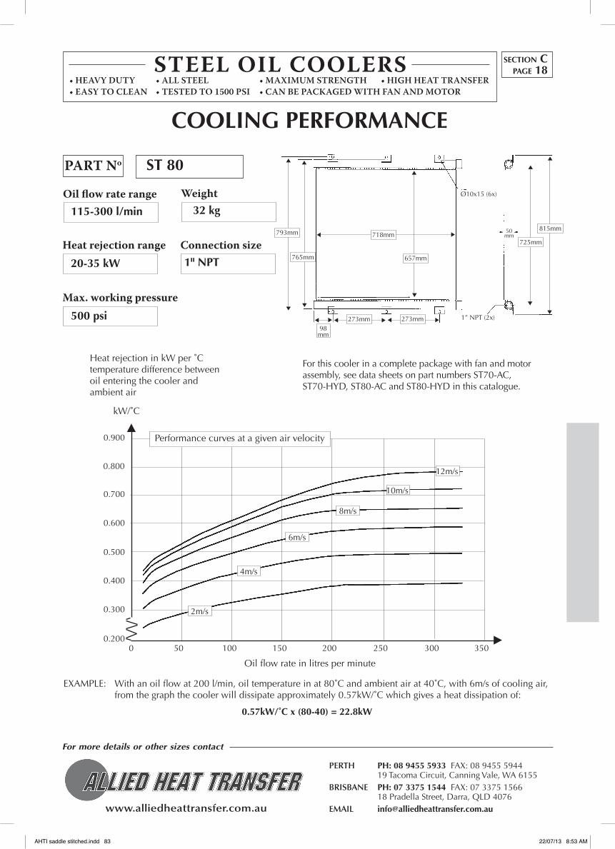
www.alliedheattransfer.com.au
For more details or other sizes contact
PERTH PH: 08 9455 5933 FAX: 08 9455 5944 19 Tacoma Circuit, Canning Vale, WA 6155BRISBANE PH: 07 3375 1544 FAX: 07 3375 1566 18 Pradella Street, Darra, QLD 4076EMAIL [email protected]
STEEL OIL COOLERS• Heavy Duty • aLL SteeL • MaXIMuM StReNGtH • HIGH Heat tRaNSFeR• eaSy tO CLeaN • teSteD tO 1500 pSI • CaN Be paCKaGeD WItH FaN aND MOtOR
Oil flow rate range
PART No
Heat rejection range
Max.workingpressure
Weight
Connection size
Heat rejection in kW per ˚C temperature difference between oil entering the cooler and ambient air
0 50 100 150 200 250 300 3500.200
Oil flow rate in litres per minute
kW/˚C
EXAMPLE: With an oil flow at 200 l/min, oil temperature in at 80˚C and ambient air at 40˚C, with 6m/s of cooling air, from the graph the cooler will dissipate approximately 0.57kW/˚C which gives a heat dissipation of:
0.57kW/˚C x (80-40) = 22.8kW
ST 80
32 kg
1" NPT
115-300 l/min
20-35 kW
500 psi
0.300
0.400
0.500
0.600
0.700
0.800
0.900
COOLING PERfORMANCE
Performance curves at a given air velocity
8m/s
6m/s
4m/s
2m/s
12m/s
10m/s
718mm
657mm
793mm
765mm
273mm
Ø10x15 (6x)
50mm
98mm
1” NPT (2x)
725mm
section Cpage 18
273mm
815mm
For this cooler in a complete package with fan and motor assembly, see data sheets on part numbers ST70-AC, ST70-HYD, ST80-AC and ST80-HYD in this catalogue.
AHTI saddle stitched.indd 83 22/07/13 8:53 AM

www.alliedheattransfer.com.au
For more details or other sizes contact
PERTH PH: 08 9455 5933 FAX: 08 9455 5944 19 Tacoma Circuit, Canning Vale, WA 6155BRISBANE PH: 07 3375 1544 FAX: 07 3375 1566 18 Pradella Street, Darra, QLD 4076EMAIL [email protected]
ModelsST10-80
0 50 100 150 200 250 300 350 l/min
100 200 300 400 500 600 700
VISCOSITY CORRECTION CHART
10.0
8.0
6.0
4.0
2.0
Oil viscosity in cSt
Multiply result from
Pressure Loss Chart
by this factor
0.0
1.0
2.0
3.0
4.0
6.0
5.0
7.0
8.0
∆ P(bar)
9.0
Oil Pressure Loss at (30cSt)
section Cpage 19
ST 70/80
ST 50
ST 30
ST 10
STEEL COOLERS PRESSURE LOSS CHARTS
AHTI saddle stitched.indd 84 22/07/13 8:53 AM

www.alliedheattransfer.com.au
PERTH PH: 08 9455 5933 FAX: 08 9455 5944 19 Tacoma Circuit, Canning Vale, Western Australia 6155
BRISBANE PH: 07 3375 1544 FAX: 07 3375 1566 18 Pradella Street, Darra, QLD 4076
EMAIL [email protected]
08 9455 5933
Please ring us if you can’t find what you need …
section DA
CC
ESSOR
IES: Fans, Valves/Thermo
Switches
ACCESSORIES
Contents SECTION D page
Thermal by-pass Valves 1-2
Thermostatic Fan Controls 3
12/24 volt Fans 4-6
AHTI saddle stitched.indd 85 22/07/13 8:53 AM

www.alliedheattransfer.com.au
For more details or other sizes contact
PERTH PH: 08 9455 5933 FAX: 08 9455 5944 19 Tacoma Circuit, Canning Vale, WA 6155BRISBANE PH: 07 3375 1544 FAX: 07 3375 1566 18 Pradella Street, Darra, QLD 4076EMAIL [email protected]
INLET
OIL IN
TO
TANK
THERMALBY-PASSVALVEDATASHEET
• Divertsoilflowfrom
coolertoreservoir.
• Built-inautomatic
pressure relief.
• Idealforhydrostatic
drivecircuitsduetofast
warm-up,controlledfluid
temperatures and low
return line back pressure.
• Maximumflow225L/m
These thermal by-pass values are temperature responsive to modulate return oil flow between the oil reservoir
and the oil cooler. Oil is diverted to the reservoir until the shift temperature is reached, causing flow to begin
to the cooler. At the shift temperature plus 14˚C full oil flow is diverted to the cooler. An automatic built-in
pressure value protects against excessive oil pressure.
Alsoavailable •Pressurecheckvalves •ModulatingWaterFlowValves •ThermostaticFanSwitches •OilCoolers •Thermostaticpumpcontroller
Dimensions (mm) 138l x 90h x 67th
Connection sizes 16 SAE O RING 15/16" 12 UN-2B
PART NUMBER
1100-25 38˚C 52˚C 25psi
1100-50 38˚C 52˚C 50psi
1600-25 71˚C 85˚C 25psi
1600-50 71˚C 85˚C 50psi
START SHIfT TEMPERATURE
Valve opens diverting flow
to cooler
fULL SHIfT TEMPERATURE
Valve fully open diverting
full flow to cooler
PRESSURE RELEASE SETTING
automatic diversion of oil to reservoir at
TO
COOLER
section Dpage 1
AHTI saddle stitched.indd 86 22/07/13 8:53 AM

www.alliedheattransfer.com.au
For more details or other sizes contact
PERTH PH: 08 9455 5933 FAX: 08 9455 5944 19 Tacoma Circuit, Canning Vale, WA 6155BRISBANE PH: 07 3375 1544 FAX: 07 3375 1566 18 Pradella Street, Darra, QLD 4076EMAIL [email protected]
Thermo-bypass
The ideal solution to ensure a minimum oil temperature
irrespective of the ambient temperature.
The thermo-bypass is connected parallel to the oil cooler and
will let the oil flow pass the cooler if the oil temperature is
below the closing temperature of the thermo-bypass. If the oil
temperature exceeds this temperature, the bypass closes and
oil flow is diverted through the cooler. The closing temperature
is 10˚C.
2WAYTHERMALBYPASSVALVE
ALSO AVAILABLE
3 way thermal by pass valves
pressure check valves
Modulating water flow valves
Thermostatic pump activators
Thermostatic fan switches
Oil coolers
The thermo-bypass is available with the following closing temperatures:
45˚C, 55˚C, 70˚C and 87˚C
Maximum oil flow 67 l/min.
Connections 1"
Maximum working temperature 120˚C
OILFLOW
COOLER
PRESSURECHECKVALVE
THERMO BY-PASS VALVE
section Dpage 2
AHTI saddle stitched.indd 87 22/07/13 8:53 AM
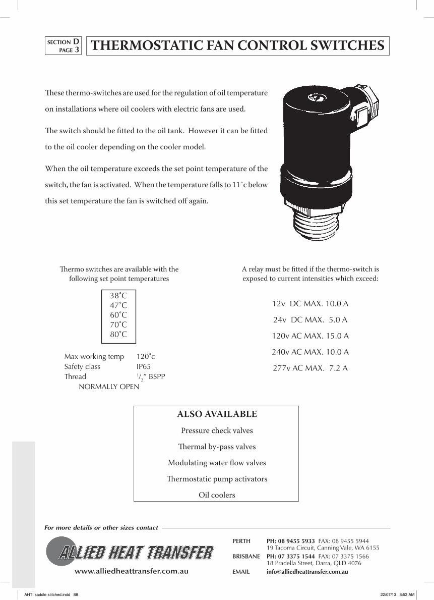
www.alliedheattransfer.com.au
For more details or other sizes contact
PERTH PH: 08 9455 5933 FAX: 08 9455 5944 19 Tacoma Circuit, Canning Vale, WA 6155BRISBANE PH: 07 3375 1544 FAX: 07 3375 1566 18 Pradella Street, Darra, QLD 4076EMAIL [email protected]
THERMOSTATIC FAN CONTROL SWITCHES
These thermo-switches are used for the regulation of oil temperature
on installations where oil coolers with electric fans are used.
The switch should be fitted to the oil tank. However it can be fitted
to the oil cooler depending on the cooler model.
When the oil temperature exceeds the set point temperature of the
switch, the fan is activated. When the temperature falls to 11˚c below
this set temperature the fan is switched off again.
A relay must be fitted if the thermo-switch is exposed to current intensities which exceed:
12v DC MAX. 10.0 A
24v DC MAX. 5.0 A
120v AC MAX. 15.0 A
240v AC MAX. 10.0 A
277v AC MAX. 7.2 A
ALSO AVAILABLE
pressure check valves
Thermal by-pass valves
Modulating water flow valves
Thermostatic pump activators
Oil coolers
38˚C47˚C60˚C70˚C80˚C
Max working temp 120˚cSafety class IP65Thread 1/2” BSPP NORMALLY OPEN
Thermo switches are available with the following set point temperatures
section Dpage 3
AHTI saddle stitched.indd 88 22/07/13 8:53 AM
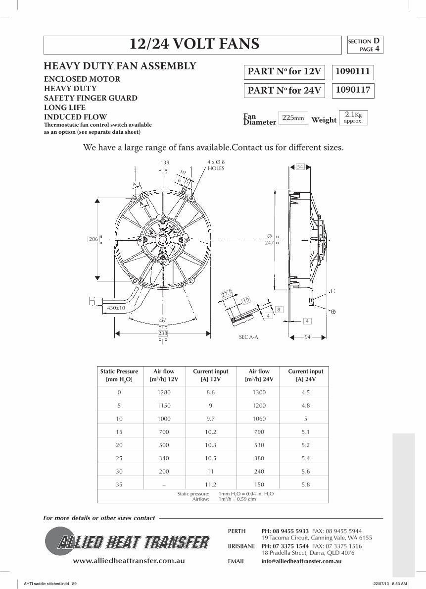
www.alliedheattransfer.com.au
For more details or other sizes contact
PERTH PH: 08 9455 5933 FAX: 08 9455 5944 19 Tacoma Circuit, Canning Vale, WA 6155BRISBANE PH: 07 3375 1544 FAX: 07 3375 1566 18 Pradella Street, Darra, QLD 4076EMAIL [email protected]
12/24VOLTFANS
FanDiameter
PART No for12VENCLOSED MOTORHEAVY DUTYSAFETY FINGER GUARDLONG LIFEINDUCED FLOWThermostaticfancontrolswitchavailableasanoption(seeseparatedatasheet)
2.1Kgapprox.
1090111
PART No for24V
225mm
HEAVY DUTY FAN ASSEMBLY
Weight
Static Pressure Air flow Current input Air flow Current input [mm H2O] [m3/h] 12V [A] 12V [m3/h] 24V [A] 24V
0 1280 8.6 1300 4.5
5 1150 9 1200 4.8
10 1000 9.7 1060 5
15 700 10.2 790 5.1
20 500 10.3 530 5.2
25 340 10.5 380 5.4
30 200 11 240 5.6
35 – 11.2 150 5.8
Static pressure: 1mm H2O = 0.04 in. H2O Airflow: 1m3/h = 0.59 cfm
section Dpage 4
1090117
Ø247
94
4
54
84
1927.5
SEC A-A238
46˚
430±10
206
A
A
139
106
4 x Ø 8 HOLES
We have a large range of fans available.Contact us for different sizes.
AHTI saddle stitched.indd 89 22/07/13 8:53 AM

www.alliedheattransfer.com.au
For more details or other sizes contact
PERTH PH: 08 9455 5933 FAX: 08 9455 5944 19 Tacoma Circuit, Canning Vale, WA 6155BRISBANE PH: 07 3375 1544 FAX: 07 3375 1566 18 Pradella Street, Darra, QLD 4076EMAIL [email protected]
12/24VOLTFANS
FanDiameter
ENCLOSED MOTORHEAVY DUTYSAFETY FINGER GUARDLONG LIFEINDUCED FLOWThermostaticfancontrolswitchavailableasanoption(seeseparatedatasheet)
2.5Kgapprox.
1090108
305mm
HEAVY DUTY FAN ASSEMBLY
Weight
Static Pressure Air flow Current input Air flow Current input [mm H2O] [m3/h] 12V [A] 12V [m3/h] 24V [A] 24V
0 2750 16.5 2900 9.4
5 2450 15 2700 9.3
10 2100 16 2400 9
15 1600 17 2000 9.4
20 1000 17.8 1300 9.6
25 700 18.5 950 10
30 450 19 700 10.3
35 450 20 450 10.8
Static pressure: 1mm H2O = 0.04 in. H2O Airflow: 1m3/h = 0.59 cfm
430±
10
90˚
Ø340
21˚
6˚40'
60˚
Ø337
10
95.5
331
573.5
6
323315
section Dpage 5
1090110
PART No for12V
PART No for24V
We have a large range of fans available.Contact us for different sizes.
AHTI saddle stitched.indd 90 22/07/13 8:53 AM

www.alliedheattransfer.com.au
For more details or other sizes contact
PERTH PH: 08 9455 5933 FAX: 08 9455 5944 19 Tacoma Circuit, Canning Vale, WA 6155BRISBANE PH: 07 3375 1544 FAX: 07 3375 1566 18 Pradella Street, Darra, QLD 4076EMAIL [email protected]
12/24VOLTFANS
FanDiameter
ENCLOSED MOTORHEAVY DUTYLONG LIFEINDUCED FLOWThermostaticfancontrolswitchavailableasanoption(seeseparatedatasheet)
2.3Kgapprox.
1090107
1090106
385mm
HEAVY DUTY FAN ASSEMBLY
Weight
Static Pressure Air flow Current input Current input [mm H2O] [m3/h] [A] 12V [A] 24V
0 4000 18.5 9.3
5 3450 19.7 10.0
10 2900 20.1 10.2
12.5 2650 20.9 10.2
15 2350 20.2 10.2
17.5 2000 20.2 10.1
20 1600 19.5 9.8
25 850 19.5 9.6
30 - 19.2 9.6
Static pressure: 1mm H2O = 0.04 in. H2O Airflow: 1m3/h = 0.59 cfm
414
88
126
28
19 48
400
206.5
358
430±
10
A
A45˚
90˚
40531
section Dpage 6
PART No for12V
PART No for24V
We have a large range of fans available.Contact us for different sizes.
AHTI saddle stitched.indd 91 22/07/13 8:53 AM

NOTES
AHTI saddle stitched.indd 92 22/07/13 8:53 AM