distribution switchgearmarkswist.com/markpersonal/ebooks/distributed switchgear_fixed1.pdfvolume 53...
TRANSCRIPT


IET PowEr and EnErgy sErIEs 46
Series Editors: Professor A.T. Johns Professor D.F. Warne
Distribution Switchgear

Other volumes in this series:
Volume 1 Power circuit breaker theory and design C.H. Flurscheim (Editor)Volume 4 Industrial microwave heating A.C. Metaxas and R.J. MeredithVolume 7 Insulators for high voltages J.S.T. LoomsVolume 8 Variable frequency AC motor drive systems D. FinneyVolume 10 SF6 switchgear H.M. Ryan and G.R. JonesVolume 11 Conduction and induction heating E.J. DaviesVolume 13 Statistical techniques for high voltage engineering W. Hauschild and
W. MoschVolume 14 Uninterruptable power supplies J. Platts and J.D. St Aubyn (Editors)Volume 15 Digital protection for power systems A.T. Johns and S.K. SalmanVolume 16 Electricity economics and planning T.W. BerrieVolume 18 Vacuum switchgear A. GreenwoodVolume 19 Electrical safety: a guide to causes and prevention of hazards
J. Maxwell AdamsVolume 21 Electricity distribution network design, 2nd edition E. Lakervi and
E.J. HolmesVolume 22 Artificial intelligence techniques in power systems K. Warwick, A.O. Ekwue
and R. Aggarwal (Editors)Volume 24 Power system commissioning and maintenance practice K. HarkerVolume 25 Engineers’ handbook of industrial microwave heating R.J. MeredithVolume 26 Small electric motors H. Moczala et al.Volume 27 AC-DC power system analysis J. Arrill and B.C. SmithVolume 29 High voltage direct current transmission, 2nd edition J. ArrillagaVolume 30 Flexible AC Transmission Systems (FACTS) Y-H. Song (Editor)Volume 31 Embedded generation N. Jenkins et al.Volume 32 High voltage engineering and testing, 2nd edition H.M. Ryan (Editor)Volume 33 Overvoltage protection of low-voltage systems, revised edition P. HasseVolume 34 The lightning flash V. CoorayVolume 35 Control techniques drives and controls handbook W. Drury (Editor)Volume 36 Voltage quality in electrical power systems J. Schlabbach et al.Volume 37 Electrical steels for rotating machines P. BeckleyVolume 38 The electric car: development and future of battery, hybrid and fuel-cell
cars M. WestbrookVolume 39 Power systems electromagnetic transients simulation J. Arrillaga and
N. WatsonVolume 40 Advances in high voltage engineering M. Haddad and D. WarneVolume 41 Electrical operation of electrostatic precipitators K. ParkerVolume 43 Thermal power plant simulation and control D. FlynnVolume 44 Economic evaluation of projects in the electricity supply industry H. KhatibVolume 45 Propulsion systems for hybrid vehicles J. MillerVolume 46 Distribution switchgear S. StewartVolume 47 Protection of electricity distribution networks, 2nd edition J. Gers and
E. HolmesVolume 48 Wood pole overhead lines B. WareingVolume 49 Electric fuses, 3rd edition A. Wright and G. NewberyVolume 50 Wind power integration: connection and system operational aspects B. Fox
et al.Volume 51 Short circuit currents J. SchlabbachVolume 52 Nuclear power J. WoodVolume 53 Condition assessment of high voltage insulation in power system
equipment R.E. James and Q. SuVolume 55 Local energy: distributed generation of heat and power J. WoodVolume 56 Condition monitoring of rotating electrical machines P. Tavner, L. Ran,
J. Penman and H. SeddingVolume 905 Power system protection, 4 volumes

Distribution Switchgear
Stan Stewart
The Institution of Engineering and Technology

Published by The Institution of Engineering and Technology, London, United Kingdom
First edition © 2004 The Institution of Electrical Engineers New cover © 2008 The Institution of Engineering and Technology
First published 2004
This publication is copyright under the Berne Convention and the Universal Copyright Convention. All rights reserved. Apart from any fair dealing for the purposes of research or private study, or criticism or review, as permitted under the Copyright, Designs and Patents Act, 1988, this publication may be reproduced, stored or transmitted, in any form or by any means, only with the prior permission in writing of the publishers, or in the case of reprographic reproduction in accordance with the terms of licences issued by the Copyright Licensing Agency. Inquiries concerning reproduction outside those terms should be sent to the publishers at the undermentioned address:
The Institution of Engineering and Technology Michael Faraday House Six Hills Way, Stevenage Herts, SG1 2AY, United Kingdom
www.theiet.org
While the author and the publishers believe that the information and guidance given in this work are correct, all parties must rely upon their own skill and judgement when making use of them. Neither the author nor the publishers assume any liability to anyone for any loss or damage caused by any error or omission in the work, whether such error or omission is the result of negligence or any other cause. Any and all such liability is disclaimed.
The moral right of the author to be identified as author of this work has been asserted by him in accordance with the Copyright, Designs and Patents Act 1988.
British Library Cataloguing in Publication DataStewart, Stan
Distribution switchgear 1. Electric switchgear I. Title 621.3’17
ISBN (10 digit) 0 85296 107 3 ISBN (13 digit) 978-0-85296-107-0
Typeset in India by Newgen Imaging Systems (P) Ltd, Chennai First printed in the UK by MPG Books Ltd, Bodmin, Cornwall Reprinted in the UK by Lightning Source UK Ltd, Milton Keynes

This book is dedicated to those engineers who gave me help,guidance, encouragement and sound advice in my formative years.It is also dedicated to my grandchildren Hattie, Hannah, Robert and
Tom, in the hope that they will be as happy and fortunate as I was, intheir choice of careers.


Contents
Foreword xiii
Acknowledgements xv
1 Basics and general principles 11.1 Why do we have switchgear? 11.2 What is the difference between a circuit breaker and
a switch? 11.2.1 Disconnectors 21.2.2 Earth switches 21.2.3 Fuses 2
1.3 Components of switchgear 2
2 Interruption techniques 92.1 Arc interruption 92.2 Interruption mediums and techniques 92.3 Oil switchgear 102.4 Vacuum switchgear 142.5 SF6 switchgear 20
2.5.1 Gas pressure 222.5.2 Contact design 232.5.3 Gas dryness 232.5.4 Choice of materials 24
2.6 Interrupter types 242.6.1 Rotating arc SF6 interrupters 242.6.2 The SF6 puffer interrupter 272.6.3 The relative merits of vacuum and SF6 interrupters 29
3 Fault level calculations 313.1 Impedance resolution within complicated networks 363.2 Problems 41

viii Contents
4 Symmetrical and asymmetrical fault currents 434.1 The rate of decay of the d.c. component 464.2 Decrement factor 484.3 Problems 52
5 Electromagnetic forces and contact design 555.1 Contact loading 625.2 Electromagnetic forces in three-phase faults 645.3 Arcing contact tips 655.4 Contact entry profiles 665.5 Pre-arcing and contact burning 675.6 Contact misalignment and fault making capacity 675.7 Sliding frictional resistance of contacts 685.8 Problems 70
6 Switching transients 716.1 The influence of system earthing on the transient
recovery voltage 726.2 The interruption of load current 736.3 The interruption of inductive current 746.4 The interruption of small inductive currents 776.5 Capacitor switching 806.6 Back-to-back capacitor switching 826.7 Reignition surges 84
7 Insulation 877.1 Electrical stress 877.2 Electrical discharge 897.3 Discharges in oil and gases 897.4 Discharge in solid insulation 907.5 Discharge level design practice 907.6 Voids in moulded insulation 917.7 Flashover caused by indirect discharge 927.8 Breakdown voltage and gas pressure 947.9 Solid insulation 957.10 Composite insulation 98
8 Operating mechanisms 1038.1 Materials 1038.2 Operating features 1048.3 Energy for operation 1048.4 Spring operating mechanisms 1058.5 Three-link kinematic chains 1088.6 Magnetic actuators 111

Contents ix
9 Primary switchgear 1199.1 Changes in technology 1219.2 Current and voltage transformers 1239.3 The architecture of primary switchgear 124
9.3.1 Horizontal transfer earthing 1249.3.2 Horizontal isolation with separate earthing switches 1259.3.3 Horizontal isolation with internal earthing via vertical
transfer 1269.3.4 Horizontal isolation with internal earthing via top
contact stem rotation 1309.3.5 Gas-insulated primary switchgear 132
10 Cable connected secondary switchgear 13510.1 T-off circuit protection 142
10.1.1 150 per cent transformer over-rating 14410.1.2 The transformer inrush current 14410.1.3 Discrimination with fuses on the low-voltage side 14410.1.4 No tripping due to spillage current from the time-fuse
circuit 14510.2 Time-fuse operating characteristics 14510.3 The Falcon protection scheme 14610.4 Protection where a low-voltage source is available 14810.5 Secondary distribution switchboards 148
11 Overhead conductor connected secondary switchgear 15311.1 Introduction 15311.2 Standards 15311.3 Historical background 15311.4 Pole mounted autoreclosers 15411.5 Technical terms 15711.6 Discussion on autoreclosers with HV internal solenoid
mechanisms 15811.7 Hydraulic control 15911.8 The short-circuit fault level of overhead lines 15911.9 Advances in interrupter technology 16011.10 Sectionalisers 16111.11 Protection 16311.12 Magnetic actuators and their impact on
the design of autoreclosers 16511.13 Remote monitoring and operation 16611.14 Islands of intelligence 16611.15 Autoreclosers with integral series disconnectors 17011.16 A summary of the development of autoreclosers 17111.17 Significant trends 172

x Contents
12 High-voltage fuse-links 17512.1 Construction 17512.2 Operation in service 17712.3 Fuse characteristics 179
12.3.1 Time–current characteristics 17912.3.2 Cut-off characteristics 17912.3.3 The I 2t fuse-link characteristic 180
12.4 Types of high-voltage HRC fuse-links 18012.4.1 British Standard oil-tight fuse-links 18012.4.2 British Standard air-insulated HV fuses 18112.4.3 DIN Standard air-insulated HV fuses 18112.4.4 Motor circuit fuses 18212.4.5 Instrument voltage transformer fuses 182
12.5 Full range HV fuses 18212.6 Fuse standards 18212.7 Distribution applications 18412.8 Future trends 185
13 Switchgear type tests 18713.1 Reports and certificates 18713.2 National and International Standards 18913.3 Development tests 189
13.3.1 Mechanical operations 19113.3.2 Temperature rise 19113.3.3 High-voltage tests 19713.3.4 Short-circuit tests 20013.3.5 Environmental tests 20813.3.6 Electromagnetic compatibility tests 209
14 Product conformity, quality control and service problemresolution 21114.1 Serial numbers 21114.2 Routine test 211
14.2.1 Power frequency voltage withstand tests onthe main circuit 212
14.2.2 Voltage withstand tests on the controland auxiliary circuits 212
14.2.3 Measurement of the resistance of the main circuit 21214.2.4 Mechanical operating tests 212
14.3 Automatic routine test facilities 21414.4 Design and visual checks 21514.5 Quality control 21614.6 Design review meetings 21714.7 Service problem resolution 21714.8 Minimising the problem 217

Contents xi
15 Cost of ownership 221
16 The future 22516.1 Technology 22516.2 Specifications 22616.3 Competition 22716.4 Materials 22716.5 Manufacturing 22716.6 Size 22816.7 Manufacturing base 22816.8 The shape of things to come 228
17 Further reading 23117.1 Books 23117.2 Papers and published articles 231
18 National, International and customer Specifications 235
References 241
Index 243


Foreword
Each day, during which something new is learned, should be counted as a goodday, and every engineer worth his salt, should keep a notebook to record the thingslearned for future reference. These notebooks should give references to sources ofinformation, and most importantly, contain careful notes of those things not coveredby textbooks. It was, therefore, with some humility that I accepted the invitationfrom the IEE to write this book, as I was very conscious of all the brilliant, talentedengineers and scientists who were around in my formative years, who are now goneand never published their personal engineering notes.
As a result of nearly fifty years of personal involvement in the switchgear industry,most of which being in switchgear design and development, my personal notes nowrun to several volumes. So when I was asked if I would prepare this book I took theopportunity to include a number of interesting and directly useful items from thosenotes that I hope practising engineers will find useful, and which otherwise, in timemay have been eventually lost.
You will find that certain chapters within the book are dedicated to what can bestbe described as components of distribution switchgear. These are Chapters 8 and 12which deal with operating mechanisms and high-voltage fuse-links, respectively.
I did this for the simple reason that they form an essential component withindistribution switchgear and fuse-switchgear and therefore merit a chapter in theirown right. However, in the case of high-voltage fuses, I direct the reader to the IEEPower Book on the subject in Chapter 17.
Apart from the basic knowledge building chapters, such as interruption techniquesand fault level calculations, the book contains a number of interesting and usefulsubjects that had to be learned the hard way. For example,
• Under what conditions, can well designed electrical insulation fail in service withnormal levels of electrical stress?
• For a given short-circuit current, how do you know what minimum contact loadsyou need to prevent contact burning?
• How do you set about designing a magnetic actuator operating mechanism?• How does a rotating arc SF6 interrupter work?• How do you calculate the cost of ownership of switchgear?

xiv Foreword
As the answers to these questions, and many more, will be found within this book, Ihope that you will find them useful and a source of reference. Perhaps even addingthem to your own library of notes.
Stan Stewart,Cheshire, England
June, 2003

Acknowledgements
In particular, I would like to thank Tony Turnbull of ALSTOM T&D DistributionSwitchgear Ltd. for proof reading the draft and his very helpful suggestions. I wouldalso like to thank the following people who responded to requests for informationand illustrations:
Kristine Kucera of Cooper Power Systems, USA.Tony Headley of the British Short Circuit Testing Station, UK.Patty Kozlow of Joslyn Hi-Voltage, USA.Martijn Venema of the KEMA Laboratories, Netherlands.Saviour Zammit of Medelec Switchgear, Malta.Claire Shore of Schneider Electric, UK.Michael Jackson of ALSTOM T&D, South Africa.Anne Busson of Lucy Switchgear, UK.Phil Rosen and Gordon Newbery of Cooper Bussmann, Cooper UK Ltd.Paul Miller, M&B System Sales Ltd UK.


Chapter 1
Basics and general principles
1.1 Why do we have switchgear?
A fundamental question is the type of question that children specialise in asking, and,in order to respond correctly and fully, you have to give the subject more thought thanwould otherwise be the case. My grandchildren specialise in these sorts of thoughtprovoking questions and, as I am sure that all readers are familiar with the function ofgooseberry bushes, I shall confine myself to try to address the fundamental question‘Why do we have switchgear?’.
Certain electrical distribution customer’s senior engineers used to go out of theirway to say that switchgear was a necessary evil. It cost money to buy, install andmaintain and that it did not earn any revenue. This is clearly an oversimplificationas the end user only buys electrical power, so anything that makes that possiblemust contribute to that end. These customer’s engineers did, however, concede thatswitchgear was necessary to isolate equipment that became faulty, and they couldallow the system to be split into sections to allow quick restoration of power supplies.While electricity distribution systems are relatively passive, for example, the situationin a factory, particularly one using manufacturing processes, or in a generating stationcan be active, the switchgear takes a critical part in controlling what is taking place.
So, switchgear is needed
(a) to isolate faulty equipment;(b) to divide large networks into sections for repair purposes;(c) to reconfigure networks in order to restore power supplies; and(d) to control other equipment.
1.2 What is the difference between a circuit breaker and a switch?
All switchgear must be capable of either closing or opening an electrical circuit.This is defined in standards as: ‘A general term covering switching devices andtheir combination with associated control, measuring, protection and regulatingequipment’.

2 Distribution switchgear
The question as to what the difference is between a circuit breaker and a switchcan best be answered by first of all stating what they have in common.
(a) They both can carry and interrupt their rated normal current safely.(b) They both can safely close their contacts onto a fault and carry that fault for
a rated specified time.(c) They both can safely withstand their rated power–frequency system voltage and
rated lightning impulse voltage across their contacts when in the open position.
The difference between a circuit breaker and a switch is that a circuit breaker candetect and interrupt a short-circuit fault current, whereas a switch can do neither.
In addition to circuit breakers and switches, switchgear also includes thefollowing.
1.2.1 Disconnectors
These are mechanical switches that, by definition, must be able to to carry a definedrated normal and short-circuit current, and in the open position must provide a definedlevel of insulation between their contacts. This will usually be an impulse voltagewithstand level.
1.2.2 Earth switches
These are mechanical switches capable of carrying a rated short-circuit current.Unless they are off-load devices, they will also have the ability to make onto a ratedpeak short-circuit current and carry that current safely for a specified time.
1.2.3 Fuses
Fuses must be capable of carrying a defined load current without deterioration andbe able to interrupt a defined short-circuit current. They may, or may not, includea mechanical tripping device such as a chemically propelled, or spring driven strikerpin in order to trip its associated switch or indicate that it has operated.
Most switchgear items can exist in combinations. It is quite common tofind items such as a switch-fuse or a switch disconnector. These combinationsmeet the individual technical requirements of the active elements within thecombination.
1.3 Components of switchgear
Inherent within switchgear in the open position is the need for one side of the gapto be insulated from the other, and both sides to be always insulated from earth.If we put fuses to one side, we find that switchgear is usually in the form ofa three-phase device. A simple single-phase diagram (Figure 1.1) illustrates the basiccomponent functions within switchgear. It will be seen in Figure 1.1 that the basic

Basics and general principles 3
Conductor
Operatingmechanism
Insulation
Earth
Insulation
Conductor
Moving contact
Insulated drive
Supply Load
++
Earth
Figure 1.1 Basic components within switchgear
components within switchgear are:
(a) supply-side and load-side conductors;(b) insulation from earth to support the conductors;(c) a moving contact arranged to be able to join, or separate, the two conductors;(d) a driving mechanism and its associated drive linkage to the moving contact.
The conductors (a) are required to carry electrical current and will, therefore, generateheat due to their internal resistance, and will also be subjected to mechanical forcesdue to the electromagnetic effects of electrical current. This latter subject is dealt within Chapter 5.
The insulators (b) are required to provide electrical insulation to earth to withstandboth the system voltage and any transient voltages which may be impressed uponthe switchgear. It should be remembered that the insulation within switchgear isconstantly electrically stressed throughout the life of the equipment. The insulationalso has to withstand mechanical forces that may be transmitted to the insulation fromthe conductors.
The moving contact (c), like the conductors, will also be subjected to heat andmechanical forces. It can be expected that the potential for heat generation will begreater in the moving contact as it will have a transfer contact at its hinge, and spring-loaded contacts at its separable end. It is the function of the moving contact to providean insulating gap when in the open position.
It is the function of the operating mechanism (c) to drive the moving con-tact between the open and closed positions, and to withstand the electromagnetic‘blow-off’ forces that may be generated when a short circuit occurs. Operating mech-anisms come in many different forms, but all of them are obliged to provide the powerfor operation independent of the rate at which the external power is supplied. This isto ensure that the contact speed during operation is constant. It will be appreciated that

4 Distribution switchgear
this is particularly important for manually charged operating mechanisms. Operatingmechanisms are dealt with in Chapter 8.
Not shown on the diagram, but of great importance, is the means of extinguishingthe arc that will always form when the moving contact is separated from its associatedfixed contact while carrying current. It will be appreciated that when the contacts arein the closed position, the interrupting zone of the switchgear acts as a conductor,and in order to interrupt the flow of current, this conductor must change its condi-tion to that of an electrical insulator. This change has to take place in the shortestpossible time in order to minimise the effects of arcing. Depending upon the type ofinterrupting technology used, these effects may result in heat, gas and pressure gener-ation as well as contact melting and erosion. Interrupting techniques are dealt with inChapter 2.
In addition, and also not shown, are the earthing facilities. The functionality ofa circuit breaker should include a means of earthing in order to allow safe workingconditions on the unit’s associated cable and/or busbars.
In practice, the architecture of switchgear will, to some degree, be dictated bythe functionality that its application will demand. Figure 1.2 shows how the essentialcomponents are arranged in a typical horizontally isolated indoor circuit breaker. Anactual embodiment of such an arrangement is shown in Figure 1.3.
A comparison of Figures 1.2 and 1.3 will allow the physical embodiment of thecomponents to be identified. However, it will be noticed that the secondary wiring
Secondary plugs
Withdrawable truck
Operatingmechanism
Instrument andrelay chamber
Secondarysockets
Primaryisolatingsockets
Insulatedsupport
Cable
Busbars
Insulatedinterrupterdrive rod
Bushings
Earthed shutters
Interrupter
Figure 1.2 An arrangement of components in a horizontally isolated circuitbreaker

Basics and general principles 5
Figure 1.3 Indoor horizontally isolated vacuum circuit breaker Type SVB5(courtesy of ALSTOM South Africa)
connections shown in Figure 1.3 are via a cable connection, rather than a plug andsocket attached to the moving and fixed portions, respectively. It will be appreci-ated that, with horizontally isolated switchgear, the earthing facilities will requireeither a separate earthing switch, as shown in Chapter 5 (Figure 5.6), or a meansof raising and lowering of the circuit breaker element within its truck to facilitatetransfer earthing using the circuit breaker itself. The type SVB5 shown in Figure 1.3is believed to be unique in that, with the circuit breaker isolated, the connectors ofthe upper circuit breaker primary isolating contacts can be angled upwards so thatwhen the circuit breaker is re-inserted, these contacts engage with a set of earthingcontacts.
An alternative to the horizontally isolated circuit breaker is the vertically iso-lated type. This was extensively used within the United Kingdom and certain othermarkets at one stage, but is now less popular than the horizontally isolated type. Theadvantage of the vertically isolated circuit breaker is that, via a transfer position, thecircuit breaker can be used for circuit and busbar earthing without the complication ofseparate earthing switches. A diagram of the essential components within a verticallyisolated circuit breaker is shown in Figure 1.4.
Figure 1.4 shows the circuit breaker truck engaged in the normal service position.In order to provide safe working conditions on the cable, the circuit breaker wouldbe opened and then lowered to disengage the primary isolating contacts. The circuitbreaker truck would then be moved to its rear position, raised and then closed to earththe cable. A similar procedure would also be followed for earthing the busbars. The

6 Distribution switchgear
Busbar earthcontact
Instrument chamber
Busbar chamber
Current transformer chamber
Bushings
Cable earthcontact
Cable
Cable boxBushings
Operatingmechanism
Interrupter
Figure 1.4 Components within a vertically isolated circuit breaker
Figure 1.5 A Type VMX switchboard of vertically isolated indoor circuit breakers(courtesy of ALSTOM T&D)

Basics and general principles 7
Busbar chamber
Fully insulated Tconnection whichcombines cabletermination andtest /earth point
Cable box
Instrument chamber
Operating mechanism
Interrupter chamber
Busbar earth switch
Fully insulatedconnectors
Current transformeraccommodation
Voltagetransformeraccommodation
Busbars
Busbar earth switch
Interrupters
Cable box
Cable
Cable testpoint
(a)
(b)
Figure 1.6 (a) Components of a fixed circuit breaker (b) Line diagram of a fixedcircuit breaker
alternative positions are indicated in Figure 1.4. The photograph in Figure 1.5 showsa typical switchboard of vertically isolated switchgear. It will be seen in Figure 1.5that two of the circuit breaker trucks are in the isolated (lower) position.
In recent years, there has been a tendency towards the use of fixed-type circuitbreakers, particularly for secondary distribution. Fixed-type indoor circuit breakershave the attraction of offering the potential for a lower cost alternative arrangementof components. This trend has come about because it was recognised that moderncircuit breakers have a very high reliability and it was argued that isolation of the

8 Distribution switchgear
Figure 1.7 The ‘Genie’ fixed-type circuit breaker (courtesy of Groupe Schneider)
circuit breaker element is an unnecessary cost and complication in its construction.A counter-argument is that a fixed circuit breaker offers lower flexibility than an iso-latable type. By this, it is meant that circuit breakers cannot be exchanged readily formaintenance, which could be important in critical locations such as within a processindustry. Typical functional elements within a fixed circuit breaker type are shown inFigures 1.6(a) and (b).
A photograph of a compact fixed circuit breaker is shown in Figure 1.7.

Chapter 2
Interruption techniques
2.1 Arc interruption
Interruption of an alternating current arc, subtended between parted electrical con-tacts, will take place if the means for electrical re-ignition is removed. The gapbetween the contacts has to change from being an electrical conductor to being anelectrical insulator at, ideally, a natural current zero.
There are a number of theories relating to the interruption of electrical current,and most of these are based upon the original theories of Cassie [1] or Slepian [2].
Cassie says:
If the energy lost from the arc column at current zero exceeds the energy input from theexternal electrical circuit, the electrical current will cease to flow.
Slepian says:
If, after current zero, the dielectric strength of the contact gap increases at a greater ratethan the transient voltage, then the circuit breaker will clear.
Slepian’s theory is illustrated in Figure 2.1.A successful interruption is shown in Figure 2.1(a) where the rate of increase of
dielectric recovery exceeds the rate of increase of the transient recovery voltagestress. Figure 2.1(b) shows a failure to clear as re-ignition occurs at a point where theimpressed voltage exceeds the dielectric strength of the gap.
2.2 Interruption mediums and techniques
If we put to one side fault current interruption using high-voltage fuses, interruptingmediums used in medium voltage distribution switchgear today are oil, vacuum andSF6 gas. There is a small percentage of units based upon hard gas, where the arc isforced into contact with materials that generate a gas to work on the arc and air breaktechnology based upon cold cathode or insulated metal plates. However, techniquessuch as these are now very rare and will not be considered here. Oil interruption

10 Distribution switchgear
Voltage stress
Dielectricstrength
Vol
tage
Time
(a) Interruption maintained
Voltage stress
Re-ignition
Dielectricstrength
Vol
tage
Time
(b) Initial interruption followed by dielectric failure
Figure 2.1 Slepian’s theory of interruption and re-ignition
technology is no longer used for new primary switchgear applications, but, althoughin declining numbers, it is still used extensively within secondary switchgear. Asthe total population of circuit breakers is currently still dominated by oil interruptingtypes, it is important that the mechanism for arc interruption in oil is understood.
2.3 Oil switchgear
Until the 1970s, there was no real alternative to using oil filled switchgear for dis-tribution applications. The origins of using oil as an electrical switching medium areunclear. It can only be assumed that the high dielectric strength of oil encourageda pioneer to separate electrical contacts under oil. This was very successful and theassumption was that the oil quenched the arc. As a result, oil was widely taken up andused for many decades before the true reason for its effectiveness as an interruptingmedium was discovered.
As electrical systems grew in size and power, they started to fail spectacularly.This resulted in ground breaking research being carried out by the ERA, which in thelate 1920s at the Carville Power Station in the UK, determined what actually tookplace during oil interruption [3].
The experimental apparatus comprised a fixed and moving contact, submergedin oil, with a series of evacuated and sealed glass phials, arranged so that the neckof each phial was broken by the moving contact as it opened, allowing the phials tocollect whatever gases were present. Analysis of the contents of the phials showedthat the gases were predominantly hydrogen and acetylene. It was deduced that theeffectiveness of oil circuit breakers was due to the presence of hydrogen, which,because of its low atomic weight, was capable of travelling at very high velocitiesand, therefore, provided a means for the rapid extraction of heat from the arc column.The oil circuit breaker was, in reality, a gas circuit breaker. This discovery helpedengineers to understand that the mechanism of arc interruption involves rapid heatremoval from the arc channel.

Interruption techniques 11
It is both interesting and alarming to note that the investigators carried on withtheir experiments by building and testing a hydrogen-filled circuit breaker, whichconfirmed their belief that it was the gas which enabled interruption and not, asoriginally thought, the oil. Fortunately, the danger of the hydrogen circuit breaker wasfully realised at that time and there never was an intention to introduce a commercialversion.
All oil circuit breakers are fitted with gas vent pipes. These are intended to ventthe hydrogen produced during arc interruption, outside of the switchgear, or thesubstation, as there would be a danger of an internal explosion if the gas was ignitedby, for example, a small arc in the circuit breaker auxiliary contacts. It is, therefore,very important that all gaskets and seals in the gas vent system are maintained in goodcondition. However, if the gas seals allow gas to enter the circuit breaker structure, itwill take a finite time to disperse. A concentration of 5 per cent hydrogen or greateris required for the gas to ignite. Consider a circuit breaker that had cleared a faultand, as a result of ineffective gaskets, had partially been filled to 40 per cent withhydrogen gas.
Figure 2.2 shows that this circuit breaker would be liable to experience an internalexplosion if a spark was produced when it was called upon to close within 8.5 min ofthe initial clearance.
Whenever visiting a substation having oil switchgear, it is good practice to exam-ine the vent outlets of any circuit breakers, especially those set for autorecloseoperations, as the presence of a small volume of oil, which would have been exhaustedwith the gas, would indicate that the circuit breaker has been working, and may needattention.
Oil circuit breakers were originally of the ‘plain break’ type. In this type of circuitbreaker, the contacts were separated under oil without any form of arc control device.It was found that a significant increase in rated fault level could be obtained if thearc was enclosed by, what is now known as an ‘arc control pot’. Initially, arc controlpots were arranged to vent the gases produced by the arc axially in the direction ofthe moving contact. In effect, this was an ‘explosion pot device’. Further increases in
40
0 2 4 6 8 10
35
30
25
20
15
10
5
0
Hyd
roge
n (%
)
Time (min)
Figure 2.2 Dissipation time for hydrogen gas

12 Distribution switchgear
Gas vents
Arc control pot
Fixed contact
Erosion resistantmaterial
Moving contact
Figure 2.3 Diagrammatic cross-section of an arc control device
interrupting ability were realised when the gases were restricted from venting axiallyand instead were directed transversely across the arc channel. The relatively smallinternal volume of an arc control pot meant that very high internal gas pressureswere generated during interruption of fault current. Figure 2.3 is a diagrammaticcross-section through an arc control pot. It will be seen that the pot encloses thefixed contact and has an orifice to allow the moving contact to enter. Both the fixedand moving contacts were fitted with erosion-resistant arc control tips to allow thecontacts to meet the specified maximum number of six break operations at the fullyasymmetrical fault current level without maintenance. It was the practice of someswitchgear designers to arrange for a channel to be formed in the vent block to guidethe arc into the most favourable position against the vents for interruption to take place.
Due to the very high gas pressures generated during interruption, a significantforce was caused to act upon the end of the moving contact, which had to be con-trolled by dashpots within the contact drive system. This was to prevent an excessivelylong arc being created which would, in turn, create even greater forces on the mov-ing contacts. As arc interruption was the result of the gas pressure generated withinthe arc control pot, it followed that the higher the current, the greater the pressureand the more efficient the interrupter became. However, the highest pressure thatcould be tolerated was dictated by the strength of the arc control pot and, for a givenvolume, was a function of the vent area. It also followed that arc control at the lowestfault level was much less efficient for a given arc length, as a lower gas pressurewould be generated. The inherent danger was that the arc could be drawn outside thepot and, therefore, become out of control. A balance had to be achieved between theperformance at the highest and lowest fault levels by optimising the vent area. Thiswas an iterative experimental process, which frequently led to spectacular failuresand left any young witnessing engineers with a healthy respect for switchgear whichwould remain with them for life.

Interruption techniques 13
The high gas pressure inside of the arc control pot also leads to another effect,which is plunger bar imbalance. It was found that if a single-phase high-level faultoccurred in the phase furthest from the operating mechanism, the imbalance of forcescould lead to the circuit breaker experiencing mechanical problems. This was recog-nised by the testing authorities, and consequently, they introduced a single-phase testto prove that the circuit breaker could cope with the imbalance. This test remains intoday’s mandatory test schedule and is applied to circuit breakers regardless of thetype of interrupting technique.
Oil circuit breakers were often arranged to have two sets of contacts per phaseconnected in series to increase the interrupting ability and to help with mechanicalbalance. A cross-section through a typical double-break oil circuit breaker is shownin Figure 2.4.
The increase in breaking capacity achieved by employing two breaks in series perphase will not be twice that of a single break device, owing to the relative capacitanceto earth giving unequal voltage sharing.
Figure 2.4 Cross-section though a typical double-break oil circuit breaker (courtesyof ALSTOM T&D Ltd)
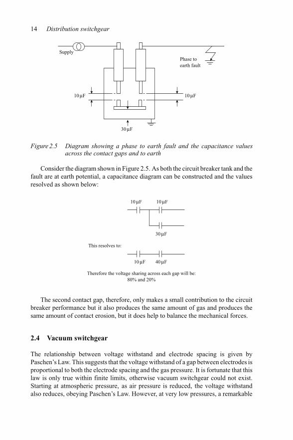
14 Distribution switchgear
SupplyPhase toearth fault
10μF 10μF
30μF
Figure 2.5 Diagram showing a phase to earth fault and the capacitance valuesacross the contact gaps and to earth
Consider the diagram shown in Figure 2.5. As both the circuit breaker tank and thefault are at earth potential, a capacitance diagram can be constructed and the valuesresolved as shown below:
10μF
10μF
10μF
30μF
40μF
This resolves to:
Therefore the voltage sharing across each gap will be:80% and 20%
The second contact gap, therefore, only makes a small contribution to the circuitbreaker performance but it also produces the same amount of gas and produces thesame amount of contact erosion, but it does help to balance the mechanical forces.
2.4 Vacuum switchgear
The relationship between voltage withstand and electrode spacing is given byPaschen’s Law. This suggests that the voltage withstand of a gap between electrodes isproportional to both the electrode spacing and the gas pressure. It is fortunate that thislaw is only true within finite limits, otherwise vacuum switchgear could not exist.Starting at atmospheric pressure, as air pressure is reduced, the voltage withstandalso reduces, obeying Paschen’s Law. However, at very low pressures, a remarkable

Interruption techniques 15
10–8 10–7 10–6 10–5 1 10210 10310–4 10–2 10–110–3
Pressure (Torr)
Bre
akdo
wn
volta
ge (
kV. D
C) 100
10
0.1
1
Gap length: 10 mmMaterial : Cu
Figure 2.6 Paschen’s curve at low pressures [4]
change takes place. Further reductions in pressure result in the withstand voltageincreasing (see Figure 2.6).
Since the first commercial introduction of vacuum interrupters in the 1970s, con-tinuous development has dramatically reduced the size and increased the short-circuitratings available. The photograph in Figure 9.5 (Chapter 9) graphically demonstratesthe changes that have taken place. The principle involved in vacuum interruption isvery old, dating from Rittenhause’s patent of 1893. However, the realisation of thepractical working interrupter must rank alongside many of the great achievementsin engineering. An arc cannot exist in a vacuum and requires metal vapour fromthe metal contacts to sustain itself, ideally until a natural current zero is reached.At this point, the metal vapour should condense back onto the contacts, denyingconductivity so that current ceases to flow. Therefore, the contact materials are allimportant to the interrupting process. In addition, the materials used for the contactsmust have the right characteristics for the conduction of normal current and theymust minimise the natural tendency of metals to cold weld when pressed togetherunder high-vacuum conditions. Further, they must not release gas when interruptingcurrent, as this would destroy the high-vacuum necessary for the whole process to berepeated many times over, during the life of the vacuum interrupter.
It follows that, as a voltage will be impressed across an interrupter following cur-rent interruption, insulating materials have to be included in the design of the vacuuminterrupter envelope. These insulating materials must be protected from condens-ing metal vapour from the contacts which would otherwise destroy their insulatingproperties. In practice, this is achieved in several different ways. Figure 2.7 is a photo-graph showing a sectioned vacuum interrupter. Protection for the internal surfaces ofthe insulating envelopes is provided by three metal shields, known as spatter shields,brazed to the centre band and end caps of the interrupter.
An alternative method of protecting the insulating envelope is to have both thefixed and moving contacts arranged to have their contact faces located within a central

16 Distribution switchgear
Figure 2.7 A sectioned type V801 vacuum interrupter (courtesy of ALSTOM T&DLtd)
canister. The inside face of this canister acts in the same way as a spatter shield, in thatcondensing metal contact vapour is collected on its inner face, well away from theinterrupter barrel insulating material. In this design of interrupter, the envelope is inthe form of a barrel brazed to each end of the central canister. If a vacuum interrupteris cut open after a large number of fault current interruptions, the spatter shield willbe found to have a copper plated appearance on its inner face, and the insulatingmaterials forming the body of the interrupter should be clean.
As the vacuum interrupter contacts have to open and close within a vacuumenvelope, it follows that the mechanical drive to the moving contact has to be ableto conduct movement into the vacuum envelope through a gas-tight seal. In practice,this is done by arranging for the moving contact to be attached to the end plate ofthe vacuum interrupter by metal bellows. These bellows are usually manufacturedfrom stainless steel which is either hydroformed to form the convolutions, or theyare manufactured by welding the edges of a number of belled annular stainless steeldiscs, such as is shown in Figure 2.7. Regardless of the method of manufacture, theintegrity of the bellows is of paramount importance. They must be able to maintainan internal vacuum over many years and many operating cycles. Therefore they mustbe tested over a very large number of operating cycles to ensure that they will not faildue to metal fatigue.
When interrupting currents of less than about 10 kA peak, the arc that is drawnbetween the contacts of a vacuum interrupter will be in the form of a number of parallelarcs. This is known as a diffuse arc and high-speed photographs show this to be like aninternally illuminated cloud with a large number of points of light dancing across the

Interruption techniques 17
contact surface. In reality, this form of arc consists of a large number of small parallelarcs that are kept separated from each other by electromagnetic force. This is becauseeach arc acts like a small magnet and the arc roots simulate the magnetic poles. Thepoles of these arcs will, therefore, exert a repelling force on each other maintainingthe arc in a diffuse state. At currents of about 10 kA and above, the main body ofeach of the small arcs will exert sufficient attractive force to overcome the pole effectand tend to cause the small arcs to fuse together into one large arc. A large singlearc will produce an extremely high temperature at the arc root, causing an excessiveamount of contact material to be vapourised, and so limiting the short-circuit currentinterrupting capability of the vacuum interrupter.
To minimise this effect and hence increase the short-circuit current rating, somemanufacturers force the arc root to move over the contact face, preventing excessivetemperatures and material vaporisation at one spot. They do this by employing whatis known as contrate contacts. A contact of this type appears in Figure 2.7 and isshown in Figure 2.8.
The surface of a contrate contact is provided with a number of slots which, by elec-tromagnetic force, will impose a self-generated rotational drive to the arc, increasingthe short-circuit rating of the interrupter.
In more recent times, it was realised that if each of the small arcs in a diffuse arccould have their magnetic polarity increased, they would continue to maintain thediffuse state by resisting the parallel current effect, and thus increase the short-circuitrating of the interrupter.
There are several different ways in which this has been achieved by manufacturers.One of these, which is patented by Cooper Power Systems, is used in the type VSAMinterrupter for their Kyle vacuum autorecloser. The fixed and moving contacts inthis interrupter are in the shape of a spiral, which causes the electromagnetic fieldof the short-circuit current, as it approaches the contact face, to produce a vector ofmagnetic field to reinforce the magnetic polarity of the small individual parallel arcs(see Figure 2.9). This technique for arc control is known as an axial magnetic field.
Toshiba introduced another very successful method of producing an axial mag-netic field to maintain the arc in a diffuse state up to very high fault current levels.The construction of the contacts using this method is shown in Figure 2.10, which
Figure 2.8 A vacuum interrupter contrate contact [4]

18 Distribution switchgear
Figure 2.9 The type VSAM axial magnetic field interrupter (courtesy of CooperPower Systems)
Stem
Coil
Electrode
Contact
I0
I0
Axi
al m
agne
tic f
ield
Figure 2.10 Contact arrangement providing an efficient axial magnetic field [5]
shows the current entering the contact arrangement via the top conductor stem. Thiscurrent then flows outwards along the four radial arms, as indicated by the arrows.The current path changes when it reaches the periphery of the contact, which it fol-lows for about 90◦, where it connects to the contact interface. The current paths in

Interruption techniques 19
the outgoing contact mirror those of the incoming contact and it is these paths whichprovide the strong axial magnetic field that maintains the arc in a diffuse state up tovery high levels of fault current.
In order to be competitive, the manufacture of vacuum interrupters must be carriedout in significant quantities. The manufacturing equipment is very specialised and,therefore, expensive. For example, consider how specialised the vacuum furnacewhich is used in the manufacture must be. The brazed joints, both metal to metal, andmetal to insulating material, have to be carried out in such a furnace at the same timein the presence of a very high-vacuum. As heat convection cannot be used, the heatnecessary for brazing can only be radiated and conducted to the joints, without causingoverheating of some of the joints and subsequent loss of brazing material. Such anarrangement requires very careful design and is expensive to implement. In addition,the manufacturing conditions have to be such that no measurable contamination canbe allowed on the internal components after full cleaning. This means that a cleanroom with positive internal pressure has to be provided. This clean room will requireair locks for access of material and personnel. Such a room is shown in Figure 2.11.
After assembly, all vacuum interrupters are subjected to routine tests to ensurecompliance with declared acceptance criteria. These tests will usually include a mea-surement of the internal vacuum which will be noted. The degree of vacuum willnormally be of the order of 10−5–10−7 torr. The vacuum interrupters will often besubjected to a second vacuum pressure measurement after a fixed elapsed time, whichby comparing the two measurements, will allow calculations of leak rate to be made,and so confirm the manufacturers’ published shelf life of the vacuum interrupter.
Figure 2.11 Assembly of vacuum interrupters in a clean room (courtesy of ALSTOMMedium Voltage Switchgear, South Africa)

20 Distribution switchgear
2.5 SF6 switchgear
At about the time that Rittenhause was filing the first patent on vacuum interrupters,work was being carried out in Paris that would lead to the creation of sulphur hexa-fluoride, SF6. Two French scientists, Moissan and Lebeau produced the first samplesof this gas at the turn of the century during laboratory experiments involving theelectrolytic action of fluorine on sulphur in a copper tube. The gas produced, SF6,was a remarkably stable gas that would rapidly recombine if dissociated. It con-sisted of a large central sulphur molecule surrounded by six fluorine molecules. Thisarrangement is shown diagrammatically in Figure 2.12.
The model shown in Figure 2.12 is a little misleading as the actual radius path ofthe electrons is much smaller than the diagram would suggest. Although the excellentelectrical insulating properties of SF6 were explored very soon after its discovery, thegas remained a scientific curiosity for many years. Apart from finding an applicationin X-ray apparatus in the 1930s, little was done to investigate its commercial prospectsuntil it began to be produced in large quantities in the mid-1940s as a by-product ofthe nuclear industrial programme.
The excellent dielectric properties of SF6 gas had suggested that it could beapplied effectively to the insulation of extra high-voltage equipment. However, it iswell known that there is little relationship between the dielectric strength of a gasand its ability to extinguish an electric arc. For example, hydrogen has only abouthalf the dielectric strength of air but it has the ability to interrupt several times thecurrent that air will interrupt under the same test conditions. It was, therefore, leftto the Westinghouse Company of the USA to discover the remarkable interruptingability of SF6 gas and in the 1950s, they went on to produce the first commercial
Figure 2.12 The SF 6 molecule (courtesy of Solvay Fluor und Derivate GmbH)

Interruption techniques 21
SF6 switchgear. At transmission voltage levels, the economic challenge to air blastswitchgear was overwhelming and many other manufacturers started to research,design and produce SF6 for their own transmission switchgear.
An SF6 enclosure will need to be as gas-tight as possible, as the gas pressure usedwill influence the voltages that can be handled and the short-circuit current that canbe interrupted. This will require rigorous gas tightness checks to be made. As SF6gas is a halogen, very sensitive gas leakage detectors can be used, which will detectvery small leaks of gas. However, experience has shown that no measurable leakcan be tolerated, as gas leaks will only get worse with time. In addition, leaks fromwelded joints in an enclosure can take up to 8 days to materialise, as the actual faultin the weld can be very small and the leak path to the measuring point can be large.Therefore, where welded joints are to form the gas envelope, it would be prudent toallow 10–14 days before declaring the enclosure as being gas-tight. Leaks past gasseals, usually caused by scratch marks on the sealing surface, can take up to 2 daysto materialise. A typical halogen leak detector, which uses negative ion capture, isshown in Figure 2.13.
SF6 gas, if released into the atmosphere, will contribute to global warming asit is a greenhouse gas. However, the contribution of SF6 towards global warmingis extremely small and the majority of SF6 gas released into the atmosphere doesnot emanate from electrical switchgear. A recent analysis of greenhouse gases in theatmosphere (which contribute to global warming) is shown in Figure 2.14. Releaseof SF6 gas into the atmosphere can occur when the gas is used in the casting processof magnesium and aluminium or as a filling medium for double glazed windows.In any case, the gas is far too expensive to be released from switchgear unneces-sarily. Gas reclamation plant is commercially available which will not only protect
Figure 2.13 A halogen gas leak detector (courtesy of Ion Science Ltd)

22 Distribution switchgear
70%
60%
50%
40%
30%
20%
10%
0%CO2 CH4 CFC-12 O3 N2O CFC-11 SF6
0.01%
Figure 2.14 Histogram showing global warming contribution from various gases
Figure 2.15 A selection of the range of SF 6 gas handling equipment (courtesy ofDILO Armaturen und Anlagen GmbH Germany)
the atmosphere but will also pay for itself in time in terms of the cost of the gassaved. Examples of gas handling equipment are shown in Figure 2.15.
In order to design successful SF6 switchgear products, there are certain areas inthe design detail that will require very careful attention.
2.5.1 Gas pressure
The internal gas pressure must be such that the SF6 gas will not start to change fromits gaseous form into a liquid when at the minimum rated ambient temperature. This is

Interruption techniques 23
–40
5060
70
8090
100
120
140
180250
5001000
–20 0 20 40 60Temperature (°C)
Pres
sure
(ba
r)
S pec
ific
vol
ume
(cm
3 /g)Liquid
Gas
26
24
22
20
18
16
14
12
10
8
6
4
2
Figure 2.16 Pressure/temperature characteristics of SF 6 gas [6]
to prevent the liquefied gas running down insulation and causing any contaminatingparticles to line up, which was a problem in the early designs.
Consider the pressure/temperature characteristic of the gas, as shown inFigure 2.16.
Outdoor SF6 switchgear has a minimum rated temperature of −25◦C. This meansthat according to Figure 2.15, the maximum internal gas pressure that can be used is5.9 bar (absolute).
2.5.2 Contact design
An electrical arc in SF6 gas will cause the gas to dissociate. However, most of thedissociated products will recombine into SF6 as the gas cools. A small percentagewill combine with vapour from the arcing contacts to form metallic fluorides in theform of a finely divided grey powder. These metallic fluorides are insulators, makingit necessary for separable contacts in arced SF6 to be of the wiping, self-cleaning type.Butt-type contacts cannot be used as these would not have surfaces free of metallicfluorides and would, therefore, be the cause of high resistance, and produce a highertemperature rise than would otherwise be the case.
2.5.3 Gas dryness
The metallic fluorides discussed earlier are, in reality, the salts of acids and must bekept completely dry to prevent the formation of acids, which would lead to subsequentinsulation failure and corrosion. The assumption that if a unit is gas tight and internallydry it will remain so is false. Under partial pressures, moisture will look on the gasenvelope as containing a vacuum and will try to ingress, usually through gas seals

24 Distribution switchgear
that include rubber materials having a degree of permeability. In practice, the drynessof the gas is controlled by the choice of materials and by the inclusion of molecularsieves, such as sodium alumino-silicate. This latter material exerts a strong attractionto moisture and is able to dry out a gas which is already very dry.
2.5.4 Choice of materials
The inclusion within SF6 gas of materials having a significant moisture content, suchas certain grades of Nylon, will have two effects. The first is that these materials willgive up their moisture to the gas, which as already described can be dangerous, and thesecond is that the material will lose a substantial measure of its mechanical strength.All materials, therefore, should be examined for moisture content and selected withthis in mind.
2.6 Interrupter types
2.6.1 Rotating arc SF 6 interrupters
The earliest practical SF6 transmission circuit breakers stored the gas stored at ahigher pressure and released this through a blast valve to a lower pressure chamber toextinguish the fault current arc. The complication of this construction was the relianceupon gas heaters to prevent the gas liquefying, and the inclusion of an internal gaspump to return the gas to a high-pressure chamber. These complications and costs ledto the introduction of the much simpler construction of ‘Puffer interrupter’ which inlater years was to be used within distribution switchgear.
The extension of the use of SF6 gas from transmission switchgear voltages todistribution switchgear voltages was not simultaneous, and lagged by almost tenyears. The reason was probably due to switchgear designers being dedicated to oneor the other of the types. However, in the early 1980s, South Wales Switchgearintroduced the type Hawkgas 12, which was interchangeable with its previous range ofindoor vertically isolated oil switchgear, and at about the same time Brush switchgearintroduced the Falcon ring-main unit and in 1982 the type PMR autorecloser. Allthree of these designs used a rotating arc interrupter. The physical arrangement of thefixed and moving contacts together with the interrupter coil is shown in Figure 2.17.It will be seen that the interrupter consists of simple separable contacts adjacent to aninterrupter coil.
In Figure 2.17, the moving contact is hinged and rotates about its axis pin (4)from the fully engaged position within the fixed contact (3) to the fully open position,concentric with the axis of the interrupter coil (2). The fixed contact has an extendedarcing finger which is arranged to be the last point of contact with the moving contactduring a contact opening operation. The interrupter coil (2) consists of a copper coilhaving one end terminated on the coil former and the other connected electrically tothe fixed contact. The principle of operation is shown in Figure 2.18.
It can be seen that an arc will be drawn between the fixed and moving contactsas the moving contact is driven towards its open, central position, co-axial with the

Interruption techniques 25
4
3
2
1
Figure 2.17 An arrangement of the contacts and rotating arc SF 6 interrupter [7]
Magnetic flux
Arc
cur
rent
Rotation ofthe arc
Arc
Fully open moving contact
Interrupter coil
Figure 2.18 Principle of operation of a rotating arc SF 6 interrupter [7]
interrupter coil. This coil is usually in the form of a thin copper strip and, as thevoltage drop across each turn of the coil is small, as when conducting fault current,the interturn insulation is usually in the form of a thin Melinex tape.
The arc root at the fixed contact is electromagnetically driven to transfer onto thecoil former and the fault current is then forced to flow through the coil, producinga magnetic field at right angles to the arc. This field causes the arc to be drivenrotationally around the inside of the coil former, by the same principle as that of

26 Distribution switchgear
25
20
10
1 2 3 4 5 6 7 8 9 ETC
Short-circuit current (kA)
Arc
dur
atio
n (m
s)
DC
B
A
Figure 2.19 Effect of interrupter coil turns on arc duration
an electrical motor, bringing it at speed into cool gas, leading to rapid fault currentinterruption. Usually this interruption takes place at the first available current zerowhen interrupting the rated short-circuit current. However, the rotating arc interrupterhas a limited capability in terms of the magnitude of the short-circuit current that it iscapable of handling. At the peak currents associated with a fault current of about 27 kArms, the coil former will collapse into a wine glass shape due to the electromagneticcrushing force imposed by the coil windings.
The arc duration at low fault current levels will be influenced by the number ofturns of foil on the interrupter coil. The greater the number of turns, the shorter thearc duration. This is shown in Figure 2.19. This figure shows the effect of the numberof coil turns on the arc duration at the rated short-circuit current. It will be seen thateach characteristic is in two parts. The initial part is a straight line increase in arcduration with current and this is followed by a reduction in arc duration to an almostconstant value, independent of the fault current. This is because the electromagneticdrive on the arc is very weak at low currents and then starts to become effective asthe current levels being interrupted are increased.
The switchgear designer has to compromise between the number of coil turns, thepeak current to be handled and the arc duration. Too many turns will give early controlof the arc duration but will limit the maximum fault current that can be handled. Thefour curves shown in Figure 2.19, A, B, C, and D, indicate the effect of increasing thenumber of coil turns and suggest that the designer compromised by selecting curve C.The actual variation in number of turns is relatively small and is usually between 17and 25.
In practice, the moving contact can either start from a fixed contact at the edge ofthe coil, as in the designs used by South Wales Switchgear Ltd and Brush SwitchgearLtd, or start from a fixed contact located on the axis of the interrupter coil, as favouredby Groupe Schneider.

Interruption techniques 27
2.6.2 The SF 6 puffer interrupter
The SF6 puffer interrupter was initially developed for high-voltage switchgear, typi-cally 145 kV and above, and is almost universally used at these voltages today. Thename ‘puffer’ is deceptive, as it does not convey the power of this technique of faultcurrent interrupter. In fact, the gas issuing through a well designed interrupter nozzlewill be travelling at the speed of sound. Typical features of an SF6 puffer interrupterare shown in Figure 2.20. As can be seen in this diagram, a typical SF6 puffer inter-rupter consists of a moving contact which has a cylinder attached that is designed tooperate against a fixed piston. At distribution voltage levels, the physical construc-tion of the SF6 puffer interrupter can vary depending upon the design philosophy ofthe manufacturer. For example, it is quite common for the puffer cylinder and/or thepiston to be formed as part of an integral insulating moulding or mouldings. Dur-ing the opening stroke, the gas within the cylinder is compressed and has a veryrestricted flow through the throat of the insulating nozzle until the nozzle clears thefixed contact.
The downstream divergence angle of the nozzle is important in order to obtainsupersonic gas flow and maximise interrupting capability. The construction is essen-tially very simple in that there is only one moving part; however, there are minor
Nozzle divergenceangle
Hollow fixed contact
p.t.f.e Nozzle
Moving contact,Nozzle and cylinderassembly
Fixed piston
Gas
flo
w
Gas
flo
w
Cylinder
Hollow movingcontact stem andcylinder move asone assembly
Figure 2.20 Typical features of an SF 6 puffer interrupter

28 Distribution switchgear
Tabl
e2.
1C
ompa
riso
nof
the
feat
ures
ofva
cuum
and
SF
6sw
itchg
ear
Feat
ure
Vac
uum
switc
hgea
rSF
6sw
itchg
ear
Adv
anta
ges
Dis
adva
ntag
esA
dvan
tage
sD
isad
vant
ages
Lon
gco
ntac
tlif
ew
hen
clos
ing
onto
,and
brea
king
faul
tcur
rent
s
Yes
–Y
esbu
tnot
usua
llyas
long
asva
cuum
–
Free
dom
from
fire
haza
rdV
irtu
alfr
eedo
mfr
omfi
reha
zard
–V
irtu
alfr
eedo
mfr
omfi
reha
zard
–
Con
sist
enta
rcin
gan
dto
tal
clea
ring
time
Yes
–Pu
ffer
isco
nsis
tent
Rot
atin
gar
cm
aysh
owan
incr
ease
atlo
wer
curr
ents
Res
trik
efr
eeop
erat
ion
Mos
ttyp
esar
ere
stri
kefr
ee–
Mos
ttyp
esar
ere
stri
kefr
ee–
Hig
h-sp
eed
faul
tcle
aran
ceM
ostt
ypes
have
shor
ttot
alcl
eara
nce
times
–Pu
ffer
type
sha
vesh
ort
tota
lcle
aran
cetim
esR
otat
ing
arc
may
show
anin
crea
seat
low
ercu
rren
ts
Litt
leor
noov
ervo
ltage
gene
ratio
n–
Susc
epta
ble
tocu
rren
tcho
ppin
gan
dre
-ign
ition
surg
esbu
twith
inno
rmal
dist
ribu
tion
appl
icat
ions
the
valu
esre
ache
ddo
notr
equi
rean
ysp
ecia
lm
easu
res
tobe
take
n
Rot
atin
gar
cpr
ovid
esso
ftin
terr
uptio
nw
ithou
tov
ervo
ltage
gene
ratio
n
Cer
tain
puff
erty
pes
will
chop
low
leve
lsof
curr
ent
No
exha
ustg
ases
No
exha
ustg
ases
–N
oex
haus
tgas
es–
Min
imal
mai
nten
ance
Low
mai
nten
ance
–L
owm
aint
enan
ce–
Sim
ple
oper
atio
nY
es–
Yes
–M
inim
alsp
ace
Nor
mal
with
air
clea
ranc
es–
Adv
anta
geca
nbe
take
nof
the
gas
insu
latio
nto
dram
atic
ally
redu
cedi
men
sion
s
–
Free
dom
from
envi
ronm
enta
leff
ects
–A
irfi
lled
cham
bers
coul
dpr
esen
tdi
ffic
ultie
sin
high
hum
idity
and
tem
pera
ture
swin
gs
The
gas
encl
osur
een
sure
sfr
eedo
mfr
omen
viro
nmen
tale
ffec
ts
–
End
oflif
edi
spos
alN
opa
rtic
ular
prob
lem
––
Will
requ
ire
the
serv
ices
ofsp
ecia
listc
ompa
nies

Interruption techniques 29
complications. For example, the fixed piston has to be fitted with a non-return valveto allow the cylinder to fill with gas during a closing stroke, so that a full charge ofgas is available for a subsequent break operation, in case the circuit breaker closesonto a fault.
The SF6 puffer interrupter has the advantage of not suffering from the limitationin fault current that was described as affecting the rotating arc interrupter. However,there are two features that must be recognised. The first is that during interruption,the gas pressure within the interrupter cylinder will be significantly increased, whichwill tend to stall movement as the operating mechanism has to overcome this gaspressure. In this regard, it is exactly opposite that of the oil circuit breaker, whichtends to accelerate the moving contacts towards the open position. The SF6 pufferinterrupter, therefore, requires a relatively large input of mechanism energy whencompared to the rotating arc interrupter, which suffers no feedback of energy fromthe arc. The second feature that should be recognised is that the blast of gas will onlybe available for a short finite time and that interruption can only take place in thatperiod, no matter when current zero occurs. The SF6 puffer interrupter, therefore, hasto be proven to have an interrupting window that will embrace at least one currentzero. By way of an example, if during short-circuit tests it is found that the minimumarc duration before interruption is 3 ms, the testing authority must be satisfied thatthe interrupter will also clear the fault current at 13 ms on a 50 Hz system.
2.6.3 The relative merits of vacuum and SF 6 interrupters (Table 2.1)
Both vacuum and SF6 switchgears are produced in many forms, as well as somewhich are hybrids, for all applications within the gambit of distribution switchgear.These include primary and secondary substations, indoor, outdoor, pad mount andpole mounted forms. The designs include dead tank, metalclad and live tank. Thechoice is wide and is made by the user on operational, economical and technicalgrounds.


Chapter 3
Fault level calculations
The result of a fault in the electrical distribution network can be relatively minor, asshown in Figure 3.1 where a dry-type cable termination was incorrectly fitted, or itcan be catastrophic, as shown in Figure 3.2. The degree of damage depends on theimpedance of the circuit carrying the fault current.
From this, it will be appreciated that when a short-circuit fault occurs in a network,such as that shown at point ‘A’ in Figure 3.3, the resulting short-circuit current willonly be limited by the elements of impedance that are remaining in the circuit.
At medium and high voltages these remaining elements are highly inductive, andhave a much smaller value of impedance than the load that was previously beingsupplied. The resulting current will, therefore, be considerably higher than the full
Figure 3.1 Electrical fault in a dry-type cable termination
32 Distribution switchgear
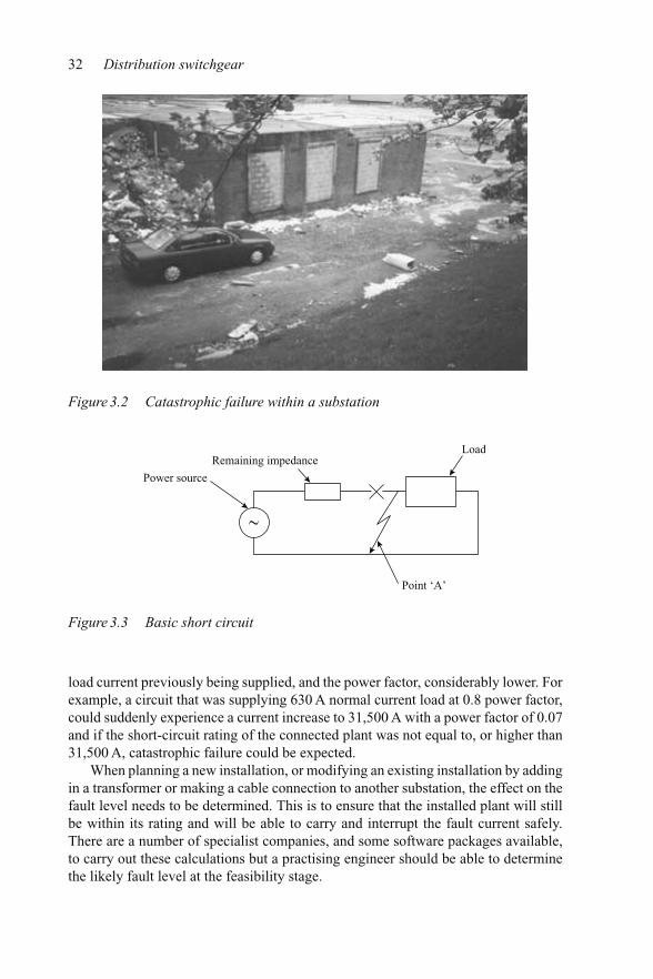
Figure 3.2 Catastrophic failure within a substation
Remaining impedanceLoad
Point ‘A’
Power source
Figure 3.3 Basic short circuit
load current previously being supplied, and the power factor, considerably lower. Forexample, a circuit that was supplying 630 A normal current load at 0.8 power factor,could suddenly experience a current increase to 31,500 A with a power factor of 0.07and if the short-circuit rating of the connected plant was not equal to, or higher than31,500 A, catastrophic failure could be expected.
When planning a new installation, or modifying an existing installation by addingin a transformer or making a cable connection to another substation, the effect on thefault level needs to be determined. This is to ensure that the installed plant will stillbe within its rating and will be able to carry and interrupt the fault current safely.There are a number of specialist companies, and some software packages available,to carry out these calculations but a practising engineer should be able to determinethe likely fault level at the feasibility stage.

Fault level calculations 33
The calculation of short-circuit currents is made easier by expressing theremaining elements of impedance in terms of their ‘per unit’ (pu) values. A definitionof which is: ‘the pu value is the voltage drop due to the element of impedance whenpassing full short-circuit current and is expressed as a fraction of the full load voltage’.This definition is worth committing to memory. The influence of the resistance ofthe remaining circuit elements at medium and high voltage levels is minimal and canbe ignored. This also makes fault level calculations much simpler, avoiding vecto-rial solutions to the inductance and resistance elements. Resolving the pu reactancesremaining in the circuit is carried out in the same way that interconnected resistancesare resolved, which is as follows:
For series connections:
Rtotal = R1 + R2 + etc.
For parallel connections:
1Rtotal
= 1
R1+ 1
R2+ etc.
Before carrying out fault level calculations, it is recommended that a diagram of thecircuit impedances be drawn, as this will help in visualising and resolving a network.This diagram should have high voltage as a top horizontal line, and earth as a bottomhorizontal line, with the circuit network connecting the two. A diagram like thisis normally useful but becomes essential when resolving networks having complexinterconnections.
An example of a very simple fault level calculation follows, where there is only oneelement of impedance. You will notice that in the calculations the network impedanceupstream from the transformer is ignored, as this will have a very small value.
Example 3.1A 200 MVA, 11 kV, three-phase transformer has an Xpu of 1.5. What is the maximumfault current that will flow in the event of a short circuit occurring on its outgoingterminals (Figure 3.4)?
MVAsc = three-phase MVAplant
Xpu= 500
1.5= 333.3 MVA = √
3 × V × Isc
Therefore
Isc = 333.3√3 × 11
= 17.5 kA
More complex systems, having different voltages between the source and the fault,may appear daunting. This is because the voltage drop is proportional to current.

34 Distribution switchgear
Transformer11 kV, 500 MVA
Xpu = 1.5
Figure 3.4 Fault current limited by transformer impedance
Therefore the pu reactance is only valid at the rated current. This is overcome byadopting a common base MVA and converting the actual plant MVA to that base. Itis important to understand that the adoption of a common base does not affect theresult. The value chosen for the MVAbase is usually one that minimises the conversioncalculations. The procedure to follow when resolving complex networks is:
(1) Adopt a base MVA.(2) Refer each reactance to the adopted base by using:
Xpu = Xplant
MVAplant× MVAbase
(3) Simplify the system component reactances to calculate the total pu reactance.(4) Calculate the fault MVA using:
MVAsc = MVAbase
MVAplant
Finally,(5) Calculate the short-circuit current from the fault MVA using MVA = √
3×V ×Isc. Therefore,
Isc = MVAsc√3 × V
An example of calculating the fault level in a system involving more than one voltageis as follows (Figure 3.5):
Example 3.2Two 60 MVA, 0.2 pu generators feed an overhead 132 kV transmission line througha single 11 kV/132 kV, 120 MVA, 0.1 pu transformer. Calculate the fault current atthe circuit breaker if a short circuit occurred on the overhead line connected to theoutgoing terminals of the 132 kV transformer. Ignore the impedance of the cablesconnecting the generators to the transformer and assume that the impedance of theoverhead line between the transformer and the fault is 1 �.

Fault level calculations 35
Generator60 MVA, 11 kV, 0.2 pu
Transformer11/132 kV, 120 MVA, 0.1 pu
1Ω Overhead line
11 kV
132 kVFault
Generator60 MVA, 11 kV, 0.2 pu
Figure 3.5 Example with generators, a transformer and more than one voltage
0.4 pu 0.4 pu Generators
0.1 pu Transformer
0.007 pu Overhead line Fault
Figure 3.6 Diagram of the network
For convenience, adopt a base MVA equal to that of the transformer, that is,120 MVA:
Xpu of overhead line = 1 � × MVAbase
V × V= 1 × 120
132 × 132= 0.007.
The pu reactance of each generator, converted to the adopted base MVA is thencalculated from:
Xpu base = Xphase × MVAbase
MVAplant= 0.2 × 120
60= 0.4 pu.
As the transformer has an MVA equal to the adopted base, its pu remains at 0.1 pu.The system can now be re-drawn in order to simplify and resolve the pu reactancevalues (Figure 3.6).
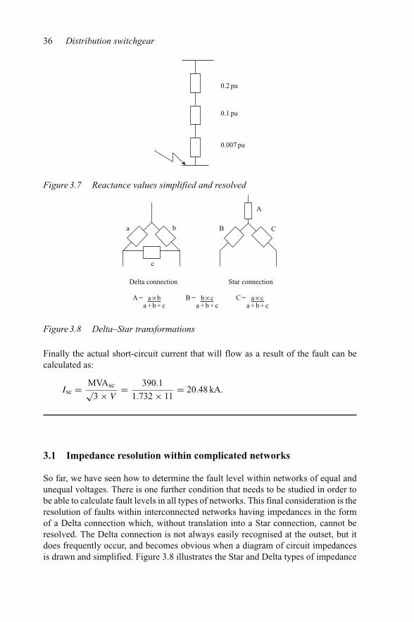
The reactance values can be simplified and resolved in the same way as resistancevalues and are as shown in Figure 3.7.
The total pu reactance value Xpu is
Xpu = 0.2 + 0.1 + 0.007 = 0.307.
The short-circuit MVA can then be calculated as:
MVAsc = MVAbase
Xpu= 120
0.307= 390.1 MVA.
36 Distribution switchgear
0.2 pu
0.1 pu
0.007 pu
Figure 3.7 Reactance values simplified and resolved
a b B
A
C
c
Delta connection Star connection
A = a×ba + b + c
B = b× ca + b + c
C = a× ca + b + c
Figure 3.8 Delta–Star transformations
Finally the actual short-circuit current that will flow as a result of the fault can becalculated as:
Isc = MVAsc√3 × V
= 390.1
1.732 × 11= 20.48 kA.
3.1 Impedance resolution within complicated networks
So far, we have seen how to determine the fault level within networks of equal andunequal voltages. There is one further condition that needs to be studied in order tobe able to calculate fault levels in all types of networks. This final consideration is theresolution of faults within interconnected networks having impedances in the formof a Delta connection which, without translation into a Star connection, cannot beresolved. The Delta connection is not always easily recognised at the outset, but itdoes frequently occur, and becomes obvious when a diagram of circuit impedancesis drawn and simplified. Figure 3.8 illustrates the Star and Delta types of impedance

Fault level calculations 37
1 pu
4 pu
Breaker ‘A’
Breaker ‘B’
0.25 pu
0.25 pu
1.6 pu
0.25 pu
0.25 pu
8.0 pu
Fault
1 pu
Figure 3.9 A complex network
connections and the relatively simple calculations that have to be made in order toallow the impedance diagrams to be simplified.
It can be seen that the Delta connection cannot be directly resolved into series andparallel impedances for circuit simplification and resolution. In order to overcomethis problem, a Delta to Star transformation has to be carried out. The Star equivalentimpedance of the Delta configuration can be calculated as shown. The followingincludes examples that require Delta–Star transformations to arrive at the answer.
Example 3.3Five 11 kV primary substations are interconnected as shown in Figure 3.9. The puvalues given are to a 100 MVA base. Calculate the fault level at the point indicatedassuming that all circuit breakers are closed.
We start by representing the network graphically (Figure 3.9), as in Figure 3.10,showing the pu values at the adopted base value of 100 MVA.
This simplifies to Figure 3.11.It can be seen that the 4.0, 0.5 and the 0.25 impedances are Delta connected and
will have to be converted to a Star connection in order to further simplify the diagram.The Delta element is shown in Figure 3.12.

38 Distribution switchgear
1.0
0.25
1.0
8.0 1.6
0.250.25
0.25
4.0
Figure 3.10 Diagrammatic representation of the network
4.0
0.25
0.25
0.58.0
1.6
0.25
0.2
Figure 3.11 Simplification of the network diagram
4.0 (a) 0.5 (b)
0.25 (c)
Figure 3.12 The Delta element within the network
As shown earlier, the equivalent limbs of the Star connection are calculated bydividing the product of adjacent sides by the sum of all three sides. The equivalentStar connection is then as given by Figure 3.13.
This further simplifies the network to that shown in Figure 3.14. This can now befurther simplified, as shown in Figure 3.15.

Fault level calculations 39
Similarly B = 0.21
A = = 0.42 4×0.5
4 + 0.5 + 0.25
C = 0.0263
Figure 3.13 Star connected equivalent to the Delta element in the circuit
0.42
0.21
0.25
0.0263
8.0
0.25
1.6
Figure 3.14 Further simplification of the network
0.42
0.46
8.0
0.2263
0.25
1.6
Figure 3.15 Further resolution of the network
It will be seen that impedances 0.42, 0.2263 and 8.0 form another Delta connectionwhich has to be transformed into a Star connection to allow the impedance of thenetwork to be resolved (Figure 3.16).
The network now changes to that shown in Figure 3.17. This can then be simplifiedto Figure 3.18. These networks can be further simplified as shown in Figures 3.19and 3.20.

40 Distribution switchgear
Similarly B = 0.011
A = = 0.3880.42×80.42 +8 + 0.2263
C = 0.21
Figure 3.16 Transformation of the Delta element into a Star connection
0.388
0.011
0.46
0.21
0.25
1.6
Figure 3.17 Network with Star element
0.388
0.471 0.46
1.6
Figure 3.18 Further simplification
0.388
0.232
1.6
Figure 3.19 Simplification to give parallel impedances

Fault level calculations 41
0.62 1.6 = 0.447
Figure 3.20 Final simplification
The total pu reactance in the circuit is, therefore, 0.447 pu.The fault MVA is derived from
MVAbase
Xpubase= 100 MVA
0.447
= 223.7 MVA
Therefore:
three-phase fault current = 223.7√3 × 11
.
= 11.74 kA rms.
The following are further problems for you to resolve in your own time, using theprevious complex network example.
3.2 Problems
(1) Calculate the symmetrical fault current that would have flowed if circuit breaker‘A’ had been open.
(2) Similarly, calculate the symmetrical fault current that would have flowed ifcircuit breaker ‘B’ was the only circuit breaker open.
(3) What would have been the symmetrical fault current if both circuit breakers ‘A’and ‘B’ had been open?
(4) Calculate the symmetrical fault current if the pu reactance of all of thetransformers was 1 pu and all breakers were closed.


Chapter 4
Symmetrical and asymmetrical fault currents
In the previous chapter, we saw how to calculate the symmetrical fault current. Thisis important from the rms heating point of view, but for distribution switchgear engi-neers, the asymmetrical current is of much greater importance for a number of reasons.The rate of rise of current is higher under symmetrical fault conditions but the peakcurrent of a fully asymmetrical fault current will induce the maximum electromag-netic force, and therefore stress, on conducting components. In addition, the totalcontact loading, which is the sum of electromagnetic and spring loading, must besufficient to prevent contact burning. A fully asymmetrical current, as it is offset, willconsist of major and minor loops. The time between current zeros in a major loopwill therefore be greater than that implied by the power frequency of the system. Thiswill induce greater stress on the interrupting system being used and, therefore, mustbe proven by test.
Medium- and high-voltage transmission and distribution of electricity takes placewithin a three-phase system. The voltage of each phase being displaced from the othersby 120 electrical degrees. This means that the initiation of a three-phase fault willalways take place with a finite value of prospective short-circuit current in at least twophases. In practice, the probability will be that all three phases will have some measureof finite prospective current. However, in an inductive circuit, an instantaneous valueof prospective current cannot flow as the back e.m.f. of the circuit will provide anequal and opposite prospective current, starting the actual current flow at zero andgiving the subsequent current wave a measure of asymmetry. An example showingthe maximum phase values of asymmetrical current and d.c. component of transientcurrent is given in Figure 4.1.
In the example shown in Figure 4.1, the maximum current asymmetry occurs inthe centre, or Y, phase. An analysis of the total asymmetrical current flowing showsthat it is made up from two components: (i) a prospective power frequency currentand (ii) a decaying transient d.c. current. In other words, the instantaneous value oftotal current at any time after fault initiation can be derived from the expression:
i = [steady state current + transient current].

44 Distribution switchgear
Instant of fault initiation
VRo
VYo
VBo
IR
IY
d.c. component
IB
Figure 4.1 Oscillogram of a three-phase asymmetrical fault
Given that i = instantaneous value of current, I = the symmetrical peak current,� = radians/s, φ = switching angle, t = time after fault initiation, L = circuitinductance, R = circuit resistance, the steady state current at any instant in time, i′,is given by the expression
i′ = I sin(�t + φ)
and the value of the transient d.c. component of current, i′′, at any instant in timeafter fault initiation is given by the expression
i′′ = I sin φe−Rt/L.
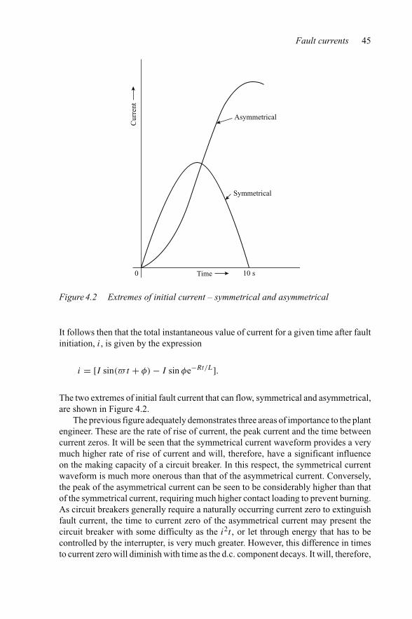
Fault currents 45
0
Asymmetrical
Symmetrical
Time
Cur
rent
10 s
Figure 4.2 Extremes of initial current – symmetrical and asymmetrical
It follows then that the total instantaneous value of current for a given time after faultinitiation, i, is given by the expression
i = [I sin(�t + φ) − I sin φe−Rt/L].
The two extremes of initial fault current that can flow, symmetrical and asymmetrical,are shown in Figure 4.2.
The previous figure adequately demonstrates three areas of importance to the plantengineer. These are the rate of rise of current, the peak current and the time betweencurrent zeros. It will be seen that the symmetrical current waveform provides a verymuch higher rate of rise of current and will, therefore, have a significant influenceon the making capacity of a circuit breaker. In this respect, the symmetrical currentwaveform is much more onerous than that of the asymmetrical current. Conversely,the peak of the asymmetrical current can be seen to be considerably higher than thatof the symmetrical current, requiring much higher contact loading to prevent burning.As circuit breakers generally require a naturally occurring current zero to extinguishfault current, the time to current zero of the asymmetrical current may present thecircuit breaker with some difficulty as the i2t , or let through energy that has to becontrolled by the interrupter, is very much greater. However, this difference in timesto current zero will diminish with time as the d.c. component decays. It will, therefore,

46 Distribution switchgear
be a function of the time from fault initiation to initiation of arcing within the arccontrol device of the circuit breaker.
4.1 The rate of decay of the d.c. component
The rate of decay of the d.c. component is important to the switchgear engineer asit has a significant influence on the peak current and the time to current zero. Theseaffect the contact loading, electromagnetic forces and the arc energy that has to besafely handled. In the earlier expression for the instantaneous value of current, thesecond element within the brackets gives the value of d.c. current. For a given pointon wave of fault initiation, time after fault and symmetrical current, the value ofthe power factor has a large influence on rate of decay of the fault current. This isdemonstrated in the following graph (Figure 4.3), which plots the d.c. component ofcurrent against time for power factors of 0.05, 0.1 and shows that the rate of decayincreases with power factor.
The actual value of d.c. component to be used for type tests is specified in IECstandards. This is in the form of a graph which plots the d.c. component against thetime interval from initiation of the short circuit. Currently, work is being carried out toprovide two curves for distribution switchgear, one for standard applications havinga time constant of 45 ms, and a new one for special applications that involve high d.c.components, with a time constant of 120 ms. These curves are shown in Figure 4.4.
For relay-operated circuit breakers, the required percentage d.c. component isdetermined by adding a half-power frequency cycle to the opening time of the circuitbreaker, to represent the relay operating time. The total time then indicates the per-centage d.c. component. For a self-tripping circuit breaker, no time is added to theopening time.
8
5
5 1000
Effect of power factoron d.c. component of current
Power factor 0.05Power factor 0.1Power factor 0.15
Time (s)
kA
Figure 4.3 Relationship between power factor and d.c. component

Fault currents 47
100
90
80
70
60
50
40
30
20
10
00 5 10 15 20 25 30 35 40 45 50 55 60 65 70 75 80 85 90
Perc
enta
ge d
.c. c
ompo
nent
Time interval from initiation of short-circuit current
τ4 = 120 ms
τ1 = 45 ms
Figure 4.4 Relationship between percentage d.c. component and the opening timeof the circuit breaker
Fault initiation
Contact part
O
M
N
Ia.c.
Id.c.
Figure 4.5 Graphical representation of the d.c. component
Referring to Figure 4.5, mathematically, the percentage d.c. component is given by
ON − OM
MN× 100
Example 4.1A relay operated circuit breaker having a minimum opening time of 35 ms is to beinstalled in a 50 Hz circuit. If the duty is one of normal power distribution, what isthe percentage d.c. component that must be proven?

48 Distribution switchgear
As a half-power frequency cycle in a 50 Hz circuit is 10 ms, the total time to beused in the graph will be 10 ms + 35 ms = 45 ms. And the corresponding percentaged.c. component will therefore be 37 per cent.
The high d.c. applications requiring the 120 ms time constant curve are usually asso-ciated with locations near to generators and free rotating plant, such as offshore oilproduction platforms. Until the introduction of the second, high d.c. component curve,manufacturers were offering either standard circuit breakers fitted with delayed tripmechanisms, or limited proven high d.c. component test evidence. In the event ofa short circuit involving circuit breakers with a delayed trip, that trip would delayoperation until the projected d.c. component was at the level proven during type tests.This was clearly a poor second choice when compared with a circuit breaker that wasproven for this higher d.c. level of performance. This second curve will mean thatpurchasers may specify the new d.c. component in their call for tenders. However, ifthe demand for such switchgear is small, it may not justify the cost of redesign andproving tests, and other methods of dealing with the high d.c. component may haveto be employed.
4.2 Decrement factor
A convenient way to calculate the decay of the d.c. component in a circuit is to usethe decrement factor. The time constant of the circuit considered is R/L and, bydefinition, the decrement factor is given by e−R/L×0.01.
This means that at t = 0.01 s, the instantaneous value of the d.c. component ofcurrent
i′′ = I × df
where df is the decrement factor.At t = 0.02 s,
i′′ = I × e(−R/L×0.01)2
= I × df .
And at t = 0.03 s,
i′′ = I × e(−R/L×0.01)3
and so on. A numerical example will demonstrate how this works out in practice.
Example 4.2If the d.c. component of current at the instant of short circuit is 1000 A, and thedecrement factor is 0.8, calculate the curve of the d.c. component current for the first5 ms of the fault.

Fault currents 49
Time after fault initiation Calculation The d.c. component of current
0 – 10000.01 1000 × 0.8 8000.02 800 × 0.8 6400.03 640 × 0.8 5120.04 512 × 0.8 409.60.05 409.6 × 0.8 327.68
The following numerical example demonstrates how circuit parameters and point-on-wave switching information can be used to determine values associated with theresulting short-circuit current.
Example 4.3Determine the value of the peak current and the time to the first current zero for asingle-phase short-circuit test where the circuit parameters have been set to produce asteady state short-circuit current of 5 kA, given that the frequency is 50 Hz, the powerfactor 0.1 and that the fault is initiated 45◦ after the start of the positive wave of thevoltage.
A graphical representation of the conditions specified is shown in Figure 4.6.The prospective symmetrical current is that current which would flow if there
were no back e.m.f. generated within the circuit.The peak of the prospective symmetrical current
I = √2 × 5000,
= 7071 A.
At the instant of switching, t = 0, the d.c. component,
i′′ = −I sin φ
= −7071 sin(−39.3◦)= 7071 sin(39.3◦)= +4478.64 A.
The significance of the positive sign is that the d.c. component of current is positive.This, of course, is because at the instant of switching, the prospective symmetrical
current can be seen in Figure 4.6 to be negative.

50 Distribution switchgear
8
7
6
5
4
3
2
1
–2 –1 0 1 2 3 4 5 6 7 8 9 10 11 12 13 14 15 16 17 18–1
–2
–3
–4
–5
–6
–7
–8
cos–1 0.1 84.26 + 45
–39°84.26°
kA
ms
Figure 4.6 Graphical representation of voltage and prospective current
Given that the power factor, cos φ = 0.1, φ = 84.3◦ and tan φ = 10 = �L/R,
L/R = 10/� = 10/314.
Therefore
the d.c. component of current = 4478.64e−31.4t
and
the decrement factor df = e−R/10.001
= e−0.0314
and
log10 df = −0.0314 log10 e
= −0.01365.
Therefore
df = 0.9699.
The calculated values of the d.c. component of current, the symmetrical current andthe resulting asymmetrical current over the first 18 ms of current flow will be as given

Fault currents 51
in the following table:
Time from faultinitiation (t)
Prospective symmetricalcurrent (i′)
The d.c. component ofcurrent (i′′)
Asymmetricalcurrent i′ + i′′
0 −4478.64 4478.64 00.001 −2534 4344 18100.002 −372 4213 38410.003 1826 4086 59120.004 3848 3963 78110.005 5491 3944 94350.006 6599 3728 103270.007 7053 3616 106690.008 6832 3507 103390.009 5936 3402 93380.01 4456 3299 77550.011 2534 3200 57340.012 385 3104 34890.013 −1816 3010 11940.014 −3837 2920 −9170.015 −5484 2832 −26520.016 −6595 2746 −38490.017 −7060 2664 −43960.018 −6836 2584 −4252
11
10
9
8
7
6
5
4
3
2
1
05 10 16 ms
Resultant asymmetrical current
Prospective symmetrical current
d.c. component
–1
–2
–3
–4
–5
–6
–7
kA
Figure 4.7 Graphical representation of the currents

52 Distribution switchgear
The above results are shown graphically in Figure 4.7. It will be seen that thepeak current was 10,699 A and that the time to the first current zero was 13.6 ms.
The worst case condition, in terms of peak current magnitude, would only occur ifthe fault had been initiated at the point in time when the prospective symmetricalcurrent was passing through a maximum value. This is demonstrated in the followingexample:
Example 4.4Determine the maximum peak current and time to current zero using the parametersgiven in the previous example assuming that the fault is initiated as the prospectivesymmetrical current wave is passing through a maximum value.
As before, the symmetrical peak current i′ = √2 × 5000 = 7071 A.
Adopting the same calculation method as demonstrated in the previous example,the following table can be constructed:
Time fromfault initiation(t) (ms)
Prospectivesymmetrical current (i′)
The d.c. componentof current (i′′)
Asymmetricalcurrent (i′ + i′′)
0 −7071 7071 02 −5720 6638 9184 −2184 6232 40486 2079 5851 79308 5720 5493 11213
10 7071 5157 1222812 5720 4841 1056114 2184 4548 673216 −2079 4267 218818 −5720 4005 −171520 −7071 3760 −3311
This is shown graphically, in Figure 4.8.It will be seen that the asymmetrical current does not reach a natural current zero
until some 16.8 ms after the fault was initiated and the peak current experienced wassome 12,228 A. The extended time to the first current zero, and the magnitude of thecurrent peak would both have a significant influence over the design of switchgearin terms of mechanical stress, heat generation and contact loading.
4.3 Problems
(1) A single-phase 1500 MVA short-circuit test is to be carried out on a 33 kV normaldistribution circuit breaker. If the power factor of the fault is 0.1 and the fault is

Fault currents 53
13
12
11
10
9
8
7
6
5
4
3
2
1
05 10 15 17
–1
–2
–3
–4
–5
–6
–7
–8
(ms)
d.c. component
Full asymm
etrical current
Sym
met
rical
cur
rent
kA
Figure 4.8 Graph of the full asymmetrical condition
initiated 75◦ after the start of the voltage cycle, determine the maximum valueand duration of the first peak current.
(2) Using the circuit breaker and parameters given in Problem (1), determine themaximum value and duration of the first peak current if the point-on-waveof fault initiation coincided with current zero of the prospective symmetricalcurrent.
(3) If the circuit breaker in Problem (1) had an opening time of 40 ms, was relayoperated, and was to be located close to generators, or large capacity free rotatingplant, determine the maximum peak current and arc duration assuming that thepoint-on-wave of fault initiation coincided with current zero of the prospectivesymmetrical current.

54 Distribution switchgear
(4) An 11 kV relay-operated circuit breaker, having an opening time of 0.04 ms isto be located at a point in a system having a short-circuit fault level and powerfactor of 350 MVA and 0.07, respectively. Determine the maximum peak currentagainst which the circuit breaker will have to close and the d.c. component whichit will have to accommodate.

Chapter 5
Electromagnetic forces and contact design
It is a fundamental phenomenon of electricity that a force is exerted betweenconductors carrying electrical current. Under normal load current conditions, theseforces are very small, however, many engineers will not be aware of the enormousforces that are generated when the normal current is replaced by a short-circuit cur-rent which can be 40–50 times larger in magnitude. This force generated phenomenonforms the basis of many desirable aspects of electrical engineering, such as the oper-ation of measuring instruments and electrical motors, but in switchgear these forcesare potentially dangerous in terms of the stresses induced in both the conductors andtheir supporting insulators.
Two factors influence the magnitude of the electromagnetic force that will beexperienced. These are the strength of the magnetic field and the current flowing. Thefield strength can be derived from Laplace’s Law. This states that the field strengthcreated at a point in space due to the passage of electric current through a conductoris inversely proportional to the square of the distance between that point and theconductor, and is directly proportional to all other factors. The force experienced bya conductor in a magnetic field is derived from Biot–Savart’s law in that the force isproportional to the flux density and the length of the conductor.
Figure 5.1 shows two parallel conductors, length L (m) and spacing D (m), onecarrying the return current of the other in a circuit. It will be seen that the conduc-tors experience a repulsive force F (N) due to the magnetic flux produced by thiscurrent.
The magnitude of this force is given by the expression:
F = 0.2 × L × I 2
D(5.1)
where F is the force in Newtons, L the length of conductor in metres,D the conductor spacing in metres and I the instantaneous value of currentin kA.

56 Distribution switchgear
L D
F
I
I
Figure 5.1 The force on parallel conductors carrying current
Example 5.1Calculate the force acting on each of two parallel conductors having a length of 1 mand a separation of 20 cm given that the peak current flowing is 10 kA.
Force on each conductor
F = 0.2 × 1 × 102
0.2= 100 N
Assume that the arrangement of the busbars and the spacing of their supports arethe same as that shown in Figure 5.1. It will be seen that the passage of a peak faultcurrent of 10 kA will impose a point load at the upper end of each support of 50 N.
If the fault current had been 40 kA, four times the original value, the point loadingwould have been 800 N as the force is a function of the current squared. These peakforces also impose a bending moment on all support insulators which are not in linewith the direction of the force.
The calculation of the mechanical stress in support insulators is, therefore, ofparamount importance at the design stage.
It will be seen that Figure 5.1 also indicates the direction of the force. This is alsoof vital importance to the switchgear designer. The direction of the electromagneticforce can be simply determined by examination of the lines of flux produced by thepassage of current. Figure 5.2 shows current passing through a conductor and thedirection of the resulting magnetic flux. Obviously, current in the reverse directionwould produce flux in the reverse direction.
We now examine the flux produced by parallel, same direction, currents and thatproduced by parallel, opposite direction, currents. Figure 5.3 graphically shows thatin one condition we have the flux density augmented between the conductors andin the other it is diminished. A dot in the centre of the conductor indicates that thecurrent is entering perpendicular to the page, and a cross that it is leaving.

Electromagnetic forces and contact design 57
Flux
I
Figure 5.2 Direction of flux produced by a current in a conductor
Flux direction
(a) Parallel, opposite direction currents
(b) Parallel, same direction currents
F F
F F
Figure 5.3 Diagram of flux and force directions in conductors
The best way to imagine the action of electromagnetic flux is to remember thatlines of flux are always trying to maximise their length. They do this by applyinga force on the conductor, or conductors, in an attempt to move them into a morefavourable position for this maximisation to take place. It follows that a currentcarrying conductor which is not straight will experience bunching of the lines offorce at the inside of the bend and the force produced will therefore tend to straightenthe conductor, as illustrated in Figure 5.4.
This single conductor force is utilised in certain designs of air-break switchgearto assist the arc to move quickly in the direction of arc chutes for extinction, as shownin Figure 5.5.
In Figure 5.5, the slot in the moving contact causes the fault current to move downthe moving contact and then upwards again. This will cause it to meet the arc root atabout 90◦ and, therefore, will apply a driving force to the arc in an upwards direction,towards the arc control device, the arc chute, which is not shown.
Knowledge of the direction of the force generated within a single phase assiststhe switchgear designers in that the force can be used to augment the operation ofcircuit earthing devices and contact loading.

58 Distribution switchgear
Bunching of flux lines
Lines of flux
Force
Force
Figure 5.4 Force produced in a conductor by the passage of current
Moving contact
Arc
Fixed contact
Figure 5.5 Electromagnetic drive applied to an air-break circuit breaker
Moving earth contactFault current
Cable box
BusbarsCircuit breaker
Figure 5.6 Typical architecture for a horizontally isolated circuit breaker
Let us look first at circuit earthing devices. With one or two exceptions, the typicalarchitecture for a horizontally isolated circuit breaker requires a separate cable earthswitch. This is to ensure that safety measures can be put in place while work is beingcarried out on the system. Such an architecture is shown in Figure 5.6, which shows therelationship between the circuit breaker, the busbar chamber and the cable chamber.

Electromagnetic forces and contact design 59
It will be seen that the moving contact of the circuit earthing device will experiencea driving force towards the closed position from the fault current, as soon as the currentstarts to flow. If the moving contact had been arranged to close in a clockwise direction,there would have been a tendency for the moving contact to be forced towards theopen position. To overcome this, the operating mechanism for the switch in thisarrangement would need to provide much higher forces in order to close successfullyagainst a full short-circuit fault.
Switchgear designers can also take advantage of the forces produced by parallel,same direction, currents in conductors. This can be seen in the design of isolatingcontacts, similar to those shown on the circuit breaker in Figure 5.6. The designof isolating contacts ranges from simple two-contact finger arrangements to com-plex multi-finger assemblies. Consider a simple two-contact finger isolating contactarrangement, shown diagramatically in Figure 5.7.
It will be appreciated from Figure 5.3 that the electromagnetic forces producedby the passage of current will cause the two contact fingers to be attracted to eachother, increasing the loading at the point of contact. As the current carrying abilityis a function of contact loading, these electromagnetic forces will increase the faultcurrent that can be carried safely. It will also be appreciated that the forces for a givenfault current will be far greater on the isolating contacts than on the actual phases, asthese forces are inversely proportional to the conductor spacing. See expression 5.1.
Example 5.2If the two-finger isolating contact shown in Figure 5.7 had a contact length L of60 mm, and a contact spacing D of 35 mm. Ignoring any contact spring or blow-off forces, what would be the maximum electromagnetic force between the contactsurfaces if the fault current was 25 kA?
The maximum electromagnetic force will occur at the peak of fault current. Thepeak of the fault current of 25 kA will be
2.5 × Isc = 2.5 × 25 kA = 62.5 kA.
L
D
Figure 5.7 A simple arrangement of isolating contact

60 Distribution switchgear
Assuming equal current sharing, the peak current seen by each contact finger will be
62.5
2= 31.25 kA.
The force applied to the contact finger will be
F = 0.2 × L × I 2
D= 0.2 × 0.06 × 31.252
0.035= 334.82 N.
Assuming one point of contact per contact end, the maximum electromagnetic contactloading force will be
= 334.82
2
Electromagnetic contact loading will therefore be 167.41 N.
Example 5.3If the same profile dimensions and fault current used in Example 5.2 were applied toa four-finger isolating contact, what would be the new electromagnetic force appliedbetween the contact faces?
A diagrammatic end view of the contact assembly is shown in Figure 5.8. It willbe seen that the four contact fingers in Figure 5.8 conform to Figure 5.3(b) in that theyare parallel conductors carrying current in the same direction. As such, each fingerwill be attracted to each other. The forces of attraction being F1, a force associatedwith the diametrically opposite contact, and F2, the attractive force to each adjacentcontact.
Assuming equal current sharing, the maximum peak current flowing in each fingerwill be 62.5/4 = 15.625 kA and, as the contact spacing and length is identical to thatused in Example 5.2, the force
F1 = 0.2 × 0.06 × 15.6252
0.035= 83.7 N.
F2
F2
F145°
45°
Figure 5.8 End view of the four-finger isolating contact assembly

Electromagnetic forces and contact design 61
The force between adjacent contacts F2 will be greater than F1 as the spacing betweenadjacent contacts is smaller. The actual spacing, from Pythagoras, being equal to
[(D/2)2 + (D/2)2]0.2 = [17.52 + 17.52]0.2 = 24.7 mm,
and, therefore, the force
F2 = 0.2 × 0.06 × 15.6252
0.0247= 118.6 N.
The force F2 has a component which attracts each contact towards the contact surface.This, in the case of four equally spaced contacts is F2 cos 45◦, which is numericallyequal to: 118.6 × 0.7071 = 83.86 N per conductor and, as there are two adjacentconductors, the adjacent conductors will contribute to the contact loading force of:2 × 83.86 = 167.72 N.
The electromagnetic contact loading force for a fault level of 25 kA will,therefore, be:
167.72 N + 118.6 N
2 (two ends to each finger)= 143.16 N.
An example of multi-finger isolating contacts having a circular configuration can beseen in Figure 5.9 which shows two phases of a three-phase vacuum circuit breaker.
Because of other constraints, the switchgear designer cannot always use isolatingcontacts having a circular configuration, and has to use isolating contacts fixed to flatrectangular conductors, as shown in Figure 5.10 which shows the arrangement usedon a 2000 A horizontally isolated vacuum circuit breaker.
Figure 5.9 The isolating contacts of two phases of a three-phase vacuum circuitbreaker (courtesy of ALSTOM T&D Ltd)

62 Distribution switchgear
Figure 5.10 The isolating contacts of a 2000 A horizontally isolated vacuum circuitbreaker (courtesy of ALSTOM T&D Ltd)
Clearly, a contact arrangement as shown in Figure 5.10 will not provide anyelectromagnetic nip-on forces from the adjacent contact fingers. Indeed, measuresshould be taken to ensure that the adjacent fingers will not bunch together. However,the mating contacts on the reverse face will contribute to the nip-on force.
5.1 Contact loading
The required contact loading to prevent burning due to the passage of a given levelof fault current will depend upon the following:
(1) the contact materials;(2) the number of contact fingers;(3) the number of guaranteed points of contact per contact finger end;(4) the contact dimensions, that is, parallel length and spacing and(5) the ‘blow-off’ or repulsive force at the contact interface.
The total contact loading will be numerically equal to
The applied spring load + the electromagnetic load − ‘the blow-off’ force.
The total required contact loading per contact point for various contact materials isgiven in Figure 5.11.
The information given in Figure 5.11 was accumulated over many years and hasbeen found to be reasonably accurate. However, it must be remembered that the total
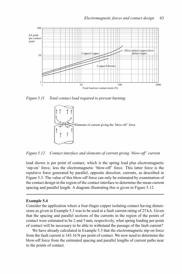
Electromagnetic forces and contact design 63
100
kA peakper contactpoint
Total load per contact point (N)
10
11 10 100 1000
Copper/Copper
Copper/Elkonite
Silver plated copper/silverplated copper
Figure 5.11 Total contact load required to prevent burning
Elements of current giving the ‘blow-off ’ force
Figure 5.12 Contact interface and elements of current giving ‘blow-off’ current
load shown is per point of contact, which is the spring load plus electromagnetic‘nip-on’ force, less the electromagnetic ‘blow-off’ force. This latter force is therepulsive force generated by parallel, opposite direction, currents, as described inFigure 5.3. The value of this blow-off force can only be estimated by examination ofthe contact design in the region of the contact interface to determine the mean currentspacing and parallel length. A diagram illustrating this is given in Figure 5.12.
Example 5.4Consider the application where a four-finger copper isolating contact having dimen-sions as given in Example 5.3 was to be used at a fault current rating of 25 kA. Giventhat the spacing and parallel sections of the currents in the region of the points ofcontact were estimated to be 2 and 5 mm, respectively, what spring loading per pointof contact will be necessary to be able to withstand the passage of the fault current?
We have already calculated in Example 5.3 that the electromagnetic nip-on forcefrom the fault current is 143.16 N per point of contact. We now need to determine theblow-off force from the estimated spacing and parallel lengths of current paths nearto the points of contact.

64 Distribution switchgear
The blow-off force per contact point will be:
= 0.2 × L × I 2
D
= 0.2 × 0.05 × 15.6252
0.02
= 122 N.
Therefore, the total force available electomagnetically will be the difference betweenthe nip-on and blow-off forces
= 143.16 N − 122 N
= 21.16 N.
However, Figure 5.11 shows that for copper contacts, a peak current of 15.625 kAwill require a total external force per contact point of 85 N.
The contact springs will, therefore, have to supply the difference in loadingbetween the electromagnetic force and the required loading from Figure 5.11.
Spring loading per point of contact
= 85 N − 21.16 N
= 63.84 N.
Care should be taken to ensure that sufficient contact loading is provided to caterfor all currents up to the maximum rating. It has been known for contact systemsto perform without a problem at maximum short-circuit rating and yet give rise tocontact burning at lower than maximum fault currents. This problem occurs when theelectromagnetic contribution to the contact loading is significant compared to thatprovided by springs. The contact loading situation should, therefore, be checked overthe full range of fault current up to the rated maximum.
5.2 Electromagnetic forces in three-phase faults
When a fault occurs in a three-phase system, the forces acting upon all three conduc-tors balance each other. In other words, the system is a closed one and no externalforce will be produced.
This can best be demonstrated by examining the forces on each conductor of athree-phase busbar system which is arranged to have all three busbars in horizontalalignment, as shown in Figure 5.13.
The following can be seen in Figure 5.13:
(1) The direction of the forces in the outer phases is largely outwards.

Electromagnetic forces and contact design 65
Red
Yellow
Blue
ForceCurrent
time
Figure 5.13 Forces in a horizontal three-phase system
(2) The direction of the forces in the centre phase is, more or less, equal in bothdirections.
(3) The frequency of the forces is twice that of the power frequency.(4) At any one instance in time the forces in each direction are equal and opposite.
It follows then that the switchgear designer should arrange for any insulation bracingthe busbars to be in line with the direction of the expected electromagnetic forceswhenever possible. It is also good practice to examine all insulation supports carefullyafter carrying out short-circuit type tests, and not just rely upon a power frequencywithstand test on the insulation. The rate of strain imposed upon the insulation isvery high, typically reaching a peak in 5 ms, and as such, a change in the modulus ofelasticity of the material should be expected. In other words, a static loading test willnot predict the behaviour of the material under the dynamic conditions that will existwhen a short-circuit fault is experienced.
5.3 Arcing contact tips
Up to now, we have only considered static conductors and isolating contacts whichare only separated under no-load conditions. Arcing contacts differ, in that they aredesigned to close and open while carrying electrical current. This current can be verylarge and there is potential for arcing damage unless special measures are taken inthe design of the contact system. Within oil and SF6 switchgear, arcing contacts areusually provided with copper–tungsten tips attached to the copper contacts. Thesetips, which are sometimes known by the generic name, Elkonite, are manufacturedby allowing copper to melt and permeate into a compressed block of tungsten powder.

66 Distribution switchgear
This results in copper within a matrix of tungsten, which gives much lower ablation ofthe contacts when subjected to an electrical arc. However, there are three importantissues that need to be recognised when this material is used. The first is that theresistivity of copper–tungsten is considerably higher than that of copper, requiring amuch higher contact force than that for copper alone. This can be seen in Figure 5.11.The second is that copper–tungsten is a brittle material and, because the arcing contactstake the impact loads associated with a closing operation, it is better attached to thecopper contacts by riveting as well as brazing. Material attached to reduce arc erosionis useless if it does not remain in place during the life of the contacts.
A classical application of brazing, screwing and riveting can be seen in the movingcontact finger of some oil circuit breakers, where the arc resistant material is in theform of a tapped ring, screwed and brazed on to the end of its associated coppercontact finger. The designer clearly having learned some expensive lessons whenpreviously the tip became detached.
Electron beam welding has also been used very successfully to attach the copper–tungsten contact tips, although this method can be expensive. To electron beam weld,a copper layer several millimetres thick is left on the surface of the copper–tungstenblock for welding purposes.
The final point to note is that copper–tungsten is a very expensive material and,therefore, should be used sparingly.
5.4 Contact entry profiles
A common mistake made by inexperienced switchgear designers is to provide boththe fixed and moving contacts with a radiused entry profile. The danger associatedwith a radiused profile is that any lateral displacement will result in a wide variationin the contact entry forces. This is because of the angle of contact, as illustrated inFigure 5.14, where the moving contact is shown in three different alignments with
Moving contact
a
b
c
Figure 5.14 The influence of contact entry profile

Electromagnetic forces and contact design 67
the fixed contact. Lateral displacement can be the result of assembly setting errors orinterface electromagnetic forces.
It can be clearly seen that the arrows a, b and c, indicating the normal to the contactface, have a wide angular variation which gives rise to wide differences in entry force.
In order to maintain a consistent entry force, a chamfer angle should be selectedwith an entry mouth greater than the maximum variation that the design allows.
5.5 Pre-arcing and contact burning
When contacts are moving towards each other, a point will be reached where thedielectric strength of the remaining contact gap is unable to withstand the voltagestress that is being imposed upon it, and electrical current will start to flow. This willresult in a measure of arc erosion of the contacts taking place. At the instant whenthe contacts initially touch, there will be no contact load, and further erosion of thecontacts will take place. This contact erosion will continue until the minimum contactloads to prevent burning are established. The current will have started at zero, at theinstant of initiation of pre-arcing, and will have risen as a sinusoidal wave regardlessof the contact loading and any contact burning. It is, therefore, important that thespeed of contact closure is as fast as possible, and that contact loading is establishedas early as possible. However, as with most things in engineering, a compromiseneeds to be made between minimising pre-arcing by minimising the time to close andprovide full contact loading, on the one hand, and the life, size and cost of the circuitbreaker on the other. It must be recognised that pre-arcing cannot be eliminated and,therefore, contact closure under short-circuit fault conditions will always lead to ameasure of contact erosion.
5.6 Contact misalignment and fault making capacity
At the instant of closure, the rate at which current rises will be a function of the pointon the prospective voltage wave that flow commences. The highest rate of increaseis that associated with a symmetrical fault current, which has, relatively, the lowestcurrent peak. Conversely, a fully asymmetrical fault current will have the highest peakcurrent but the lowest rate of current rise. In a three-phase circuit breaker, it would benormal to expect a degree of asymmetry in, at least, two phases under short-circuitconditions. However, some contact misalignment can be expected, which will meanthat the contacts in each phase will begin conducting at different times. If a circuitbreaker with misaligned contacts is closed onto an insulated three-phase fault, aswould be used for type tests, the short-circuit current will start to flow when thesecond phase becomes conducting. The worst case scenario would be when this pointof closure produces the start of a symmetrical current wave, in that this will producethe highest initial rate of current rise. When the third phase becomes conductive,a phase shift will take place, which could cause the current in one of the alreadyconducting phases to change to a full asymmetrical wave. This would mean that

68 Distribution switchgear
Worst casecurrent
0.005 0.01 0.015 (s)
Mul
tiple
s of
Isc
r.m
.s.
�
If switching angle to givesymmetrical current = �
2.5
2.0
1.0
� + 9090
� + 7575� + 6060
Figure 5.15 Worst case condition due to contact timing
the current in that phase would have started with the highest rate of current rise andthen changed to reach the highest current peak. This then means that this phase wouldbe carrying the highest current at any given time after the start of current flow; a veryonerous condition for the contact system. It is, therefore, vital that the routine testscarried out on production circuit breakers have a contact closing timing spread whichis not greater than that measured during the proving type tests. Figure 5.15 showsthe worst case conditions, where the highest current in a given time after the startof current flow occurs due to a start which is initially symmetrical and subsequentlychanges to become a full asymmetrical wave.
5.7 Sliding frictional resistance of contacts
The sliding frictional resistance of engaged finger-type cluster contacts is an importantfactor in the design of switchgear. It is particularly important for equipment havinga high short-circuit current rating, as both the number of contact fingers and theirloading could be high. In the early days of isolatable vacuum and SF6 switchgearfor distribution applications, some designs, in many companies and countries, werea direct development of the then existing oil circuit breaker types. These designsretained many of the components and design features of oil circuit breakers, however,the designers failed to take into consideration the significance of the reduced weightthat the new technology provided. Prototypes of the new switchgear very quicklyshowed up the consequences of this reduced weight as the circuit breakers could notbe isolated, because there was insufficient weight to disengage the isolating contacts.In addition to the frictional resistance to movement within isolating contacts, a similarresistance is provided by the main interrupting contacts of both oil and SF6 switchgear,

Electromagnetic forces and contact design 69
which are of the sliding ‘self-cleaning’ type. Vacuum circuit breaker contacts areinvariably of the ‘butt’ type and therefore do not offer any sliding frictional resistance.
The expression for frictional resistance is:
P = μF
where P is the frictional resistive force, μ the co-efficient of friction and F the forcebetween the contact faces.
As Figure 5.11 indicates, a non-linear relationship is involved in the requiredcontact load, and, from its trend, it follows that increasing the number of points ofcontact will reduce the total sliding frictional resistance. This is because the level ofshared current per point of contact is reduced, and, therefore, the interface contactload required to prevent burning is also reduced. The following example illustratesthe effectiveness of this method of reducing the sliding frictional contact load.
Example 5.5Given that the short-circuit rating of a circuit breaker is 25 kA r.m.s. and assumingthat the co-efficient of friction, μ, of plain copper contacts is 0.3, determine the totalfrictional sliding resistance of the six isolating contact assemblies of a circuit breaker,assuming one point of contact per end, for four, eight and 12 contacts per isolatingcontact cluster.
By definition, the peak current associated with a 25 kA r.m.s. rating is 62.5 kApeak. Therefore, with four points of contact per assembly, the peak current per pointof contact is 15.625 kA peak.
From Figure 5.11, we can see that the load per contact point to prevent burningwill be 350 N.
The total load per contact cluster will, therefore, be 4 × 350 = 1400 Nand, the total load per circuit breaker will be: 6 × 1400 = 8400 Nand the sliding frictional resistance will be: 0.3 × 8400 = 2520 N.
Similar calculations can be made for six and 12 contacts that will allow Table 5.1 tobe constructed. This is graphically shown in Figure 5.16.
Table 5.1 Calculations based on Example 5.5
a b c d = ac e = 6d f = 0.3e
No. offingers
l62.5/akA/point
Load/point(Figure 5.11)
Total loadper cluster
Total loadper cb
Slidingfrictionalload per cb
4 15.625 350 1400 8400 25208 7.813 90 720 4320 1296
12 5.208 35 420 2520 756

70 Distribution switchgear
0
500
1000
1500
2000
2500
3000
0 5 10 15Contacts/cluster
Slid
ing
resi
stan
ce (
N)
Figure 5.16 Reduction in sliding resistance with increase of contact fingers
Clearly, as can be seen above, the number of contacts within an assembly will havea marked influence upon the sliding frictional resistance.
5.8 Problems
(1) A circuit breaker has six isolating contact assemblies having 12 silver-platedcontact fingers per phase. If electromagnetic forces acting upon the fingers inthe event of a short-circuit can be ignored, what would be the maximum short-circuit rating of the isolating contact assemblies if there was one point of contactper finger end and the spring load per point was 200 N?
(2) If the fingers within the isolating contact assemblies given in Problem (1) werechanged to plain copper at the contact faces, what would be the maximumshort-circuit current that the assembly could safely carry?
(3) The isolating contact system of a circuit breaker consists of six copper fingersper pole having an effective length of 90 mm and a diametric spacing of 40 mm.Given that the spacing and parallel paths of current in the region of the pointsof contact were 1.5 and 4 mm, respectively, what would be the spring loadingnecessary at the points of contact to prevent burning, given that each finger hadonly one point of contact per end, and the short-circuit current was 40 kA r.m.s.

Chapter 6
Switching transients
A circuit breaker, when it closes or opens its contacts in an electrical circuit, causesenergy stored within elements of the circuit to be redistributed over a very shortperiod of time. During this period, voltages and currents can be produced which arefar in excess of those which are normally present when the circuit is experiencingsteady-state conditions. The levels of transient current and/or voltage produced duringdisturbance of an electrical circuit are of vital interest to those who design electricalsystems because, without taking preventive or protective measures, damage to thecircuit elements may take place.
There are three types of circuit element that make up an electrical circuit. These arethe resistance R, capacitance C and the inductance L. These are normally distributedquantities within a circuit, and in most cases can be summed for calculation purposes.
Analysis of the three elements shows that two of them, the capacitance and induc-tance, store energy, while the third, resistance, dissipates energy. In an alternatingcurrent circuit, the stored energy within the capacitance and inductance is given bythe expressions:
12Li2 for inductive elements,
12Cv2 for capacitive elements,
where i and v are the instantaneous values of current and voltage.The third element within an electrical circuit is the resistance R, which dissipates
energy. The value of the dissipated energy is given by the expression Ri2.In an alternating power system, the energy within the inductive and capacitive
circuit elements is transposed between these elements as the instantaneous values ofthe current and voltage change. A sudden change in the circuit configuration, suchas would be caused by the opening or closing of circuit breaker contacts, will causethe energy stored in the reactive elements to be redistributed. This redistributioncannot take place instantaneously, as the change in energy stored within the inductivereactance elements would require a change in current, and current cannot be created

72 Distribution switchgear
2.00
1.00
0.000.00 20.0 40.0 60.0 90.0 100
–1.00
–2.00
Vol
ts (×
106)
Figure 6.1 Result of a switching transient voltage study (courtesy of British ShortCircuit Testing Station)
or destroyed instantaneously. Similarly, an instantaneous change in voltage storedwithin the capacitive reactance circuit elements would require the application of aninfinitely large instantaneous current, which is not possible.
It can, therefore, be concluded that the redistribution of energy within a circuitfollowing a disturbance will take a finite time to achieve. This time will be very shortwhen compared with the normal power frequency of the circuit, and will depend uponthe rate of energy storage and the rate of energy dissipation. Energy conservation mustbe observed in any calculation of transient duration.
In the case of complex, highly reactive circuits, the calculation of transient over-voltage generation by circuit breaker switching operations can be difficult to evaluatewithout resorting to transient analysing equipment. However, there are specialist com-panies that will carry out system studies that are able to show, with great accuracy,the abnormal conditions that could be expected. Figure 6.1 shows an example of thetype of result that can be produced. In this case, the results of a study of switchingovervoltages are shown. It will be noted that the transient voltage disturbance had aduration of about three cycles. This duration would have been reduced had the circuitcontained more resistance.
6.1 The influence of system earthing on the transientrecovery voltage
The type of earthing used on a distribution system will have a marked effect upon thetransient recovery voltage that will appear across the contacts of a circuit breaker when

Switching transients 73
1.5E
1.5EE
E
En
E
E
EE
E
EE
EE
E
E
Unearthed neutral and three-phase to earth fault
Unearthed neutral and three-phase to earth fault
Figure 6.2 The influence of system earthing upon recovery voltage
it interrupts the flow of current. This is because within a three-phase system, currentzeros will appear at a different time in each phase and the magnitude of the voltagewhich appears across the first phase to clear will be determined by whether or not theneutral of the system is earthed. The reason for this can be seen in Figure 6.2. Thisshows the voltage in each phase diagrammatically and vectorially. In the upper view,the system has an unearthed neutral and a three-phase fault to earth. When current isflowing in all three phases, the neutral point is held by capacitance at a central pointin the vector diagram so that the voltage to earth of each phase is E. When the firstphase clears the current, the neutral point moves immediately to a mid-point betweenthe two conducting phases, giving a voltage across the first phase to clear of 1.5E
and a reduced voltage across the conduction phases. In a system where the neutral ofthe system is effectively earthed, the neutral point is held rigidly at a central point inthe vector diagram, as shown in the lower part of Figure 6.2, and each phase will seea recovery voltage with a value of E when it clears the current flowing.
We now consider the switching transients that are most likely to be experiencedby distribution switchgear. The two characteristics of the transient recovery voltage(TRV) that most influence the performance of a circuit breaker when interruptingcurrent are the rate of rise of recovery voltage (RRRV) and the TRV peak value.
6.2 The interruption of load current
When a circuit is carrying purely load current, the power factor of the circuit will beclose to unity. This means that the system voltage and the load current are in phasewith each other, with coinciding zero values. When at current zero, the load current

74 Distribution switchgear
Arc voltage0.01 0.02
Recovery voltage
Seconds
Generated voltagee
Figure 6.3 The interruption of load current
is interrupted, the recovery voltage is the relatively low-frequency system voltage.This is illustrated in Figure 6.3. In this figure, the arc suppression peak is very low andthe relatively high circuit resistance will effectively damp out superimposed voltageoscillations.
6.3 The interruption of inductive current
A distribution circuit breaker must be able to interrupt highly inductive currents intwo types of circuit: the first being the interruption of a short-circuit current and thesecond the interruption of the magnetising current of an unloaded transformer.
The transient recovery voltage of a highly inductive circuit is completely differentfrom that associated with the interruption of normal load current. This is because ofthe different instantaneous values of system voltage at current zero. During the arcingperiod, the voltage across the contacts is equal to the small voltage drop of the arccolumn, but when the current is extinguished, the voltage across the contacts will riseto the system voltage. During the interruption of load current, the system voltage isvirtually at zero when current ceases to flow and rises sinusoidally.
But, because of the lagging power factor, when current ceases to flow in aninductive circuit, the voltage on the system side contacts of the circuit breaker willattempt to rise to match the system voltage, which will be near its crest value. Due tothe oscillatory nature of the recovery voltage, it will overswing the crest voltage andapproach double its value. The natural frequency of a circuit containing capacitanceand inductance is given by the expression:
1
2π√
LC
This frequency will be superimposed upon the system voltage and the combinationwill form the recovery voltage which will appear across the contact gap when a circuitbreaker clears an inductive fault. This is illustrated in Figure 6.4.

Switching transients 75
Volts
Restriking peak=2(E + Varc)×Damping factor
(s)
0.010
Arc voltage
e
Figure 6.4 The transient recovery voltage associated with an inductive fault
0 0.01 0.02 0.03(s)
ej
Small restrikingvoltage peak
Figure 6.5 The influence of current asymmetry on TRV values
For an earthed neutral system, the peak voltage,
TRVpeak = 2 × Ddamping factor[Esystem peak voltage + Varc voltage
],
and for an unearthed neutral system, the first phase to clear will see a voltage peak of:
TRVpeak = 1.5 × 2 × Ddamping factor[Esystem peak voltage + Varc voltage
].
If we now look at the TRV that will prevail under asymmetrical fault conditions.Figure 6.5 shows the influence of current asymmetry upon the TRV. In a circuit
that is highly inductive, the power factor will be low and lagging. This means that thecurrent will lag the voltage by up to 90◦. Under asymmetrical fault conditions, thetime between current zeros of an asymmetrical major current will be far greater thanthe 10 ms that would normally be associated with a 50 Hz system. The followingare some worked examples to help give a better understanding of the calculationsinvolved in solving a relatively simple transient voltage generation problem.

76 Distribution switchgear
Example 6.1A three-phase alternator is connected to a busbar through a circuit breaker. Theinductance of the alternator is 7 mH/phase and the capacitance to earth at the circuitbreaker terminals is 0.006 μF. If a three-phase fault occurs at the circuit breakerterminals, determine the frequency of the restriking voltage and the time to peakvalue of the recovery voltage.
As was shown earlier, the natural frequency of the circuit is given by theexpression:
1
2π√
LC
Substituting the values given, the natural frequency will be:
1
2π√
7 × 10−3 × 6 × 10−9 = 24.6 kHz
and, as the number of peaks is twice the frequency, the time to peak value will be:
1
2f= 1
2 × 24.6 × 103 = 20.32 μs
Example 6.2If the alternator and circuit breaker were rated at 11 kV, and the short-circuit faultlocation was as detailed in Example 6.1, calculate the recovery voltage across thefirst phase to clear and the rate of rise of recovery voltage, given that the system hadan effectively earthed neutral. For the sake of this exercise, assume that there is noresistance in the circuit.
As the neutral of the alternator is effectively earthed, the voltage appearing acrossthe first phase to clear will be:
11√3
= 6.351 kV
and the associated peak system voltage will be:
√2 × 6.351 = 8.98 kV
and, as there is no resistance in the circuit, the over-swing peak of the oscillatorycomponent of voltage will be equal in value to the system voltage peak. Therefore,the peak value of the TRV will be:
2 × 8.98 = 17.96 kVpeak.

Switching transients 77
i0e
Current
Vg
V
Current chopping
Recovery volts
Vp
V1
Vp Voltage peak
V Power frequency crest
V1 Overswing voltage
Va Arc voltage
i0 Chopped current
e Extinction peak
Figure 6.6 Voltages and current associated with current chopping
Finally, the rate of rise of the recovery voltage, the RRRV, will be:
TRVpeak
Time to peak= 17.96 kV
20.32 μs
RRRV = 883 V/μs.
6.4 The interruption of small inductive currents
When a powerful interrupter is called upon to interrupt a very small current, thatcurrent may be forced to a premature current zero. This is known as current chopping.When the small current being chopped is associated with a large value of inductance,such as the magnetising current of an unloaded transformer, the level of voltagegenerated may be large for a small value of chopped current. The voltages and currentat the time of interruption are illustrated in Figure 6.6.
For a current, i0, forced to zero, the value of voltage generated, e′′, can becalculated by re-arranging the expression:
12 × L × i0 = 1
2 × C[e′′]2
giving
e′′ = i0√
L/C
In other words,
e′′ = i0 × Z(where Z = surge impedance of the transformer).
Current chopping has been seen to occur with all types of interrupters, includingoil, SF6 puffer, SF6 rotating arc and vacuum. Current chopping levels are often

78 Distribution switchgear
Table 6.1 Current chopped by vacuum interruptershaving different contact materials
Contact material Current chopped
Chrome copper 1.6 ACopper bismuth 5.0 A
Table 6.2 Surge impedance and magnetising currentvalues for various transformer sizes
Transformer (kVA) 500 2000 5000
Magnetising current (a) 0.4 1.1 2.6Surge impedance Z(kohms) 200 85 50
quoted by manufactures when their products display a relatively low level of currentchopping, implying that greater levels of current chopping may produce dangerousovervoltages. However, this is very misleading. Consider, for instance, the case forvacuum interrupter contact materials, and in particular a comparison of chrome copperand copper bismuth contacts.
Table 6.1 shows that, during interruption, copper bismuth will chop more thanthree times the current that would be chopped by chrome copper under the same con-ditions. However, if we look at typical oil-filled distribution transformer magnetisingcurrents and surge impedances we will find the values given in Table 6.2.
It is useful to note that, when calculating switching voltages, a damping factor(Df) of 0.25 can be used as this is a typical figure derived from core loss and measuredvalues. The maximum possible voltage experienced by no-load switching, Vp, willbe as shown in Figure 6.6:
Vp = E + e′ + e′′
With a damped oscillation about the system voltage E, the maximum voltage iscalculated by:
Vp = V√3
+ Df{
V√3
+ (Z × i0) + Va
}(6.1)
Example 6.3An unloaded 11 kV, 500 kVA oil-filled transformer is switched by a vacuum circuitbreaker having an arc voltage of 200 V. What is the maximum peak voltage that willbe generated?

Switching transients 79
From Table 6.2, it will be seen that the magnetising current will be 0.4 A and its peakvalue will be
√2 × 0.4 A, a value that will be chopped by the vacuum interrupter.
Substituting the values into the expression (6.1):
Vp = 11√3
+ 0.25{
11√3
+ (200 × 0.4 × √2) + 0.2
}Vp = 26.352 kV
It will be noted that the peak voltage calculated is well within the specified ratedimpulse level of 75 kV for 11 kV equipment and will not present an operationalproblem.
Similar calculations can be made for the other two transformer sizes given inthe previous table. The maximum peak voltages to be experienced while switchingoff-load with either type of vacuum interrupter contact material are shown in Table 6.3.
It will be noted that the voltage generated when switching unloaded oil-filled dis-tribution transformers with ratings up to 2000 kVA display the same value, regardlessof the vacuum interrupter contact material, as both types of interrupter are capableof chopping the peak of the magnetising current. However, there is a difference inthe value of voltage generated when switching a 5000 kVA transformer, because ofthe different current chopping levels displayed by the contact materials, but the peakvalue of 53 kV is still well within the rated impulse level of 11 kV equipment.
It could be argued that the current to be interrupted will increase once the trans-former supplies a load and that this will increase the level of chopped current.However, this will not increase the voltage generated as the surge impedance ofthe transformer falls away rapidly when load currents start to be supplied.
Caution should be exercised when considering the use of vacuum interruptersto control dry-type transformers. This is because the surge impedances of thesetransformers are higher that those of the oil-filled type. For these applications,surge arrestors may be necessary to prevent possible insulation damage when thesetransformers are being switched off-load.
Table 6.3 Maximum voltage generation when off-loadswitching of transformers
Transformer (kVA) 500 2000 5000
Chrome copper 26.352 kVpeak 41.04 kVpeak 27.96 kVpeakCopper bismuth 26.352 kVpeak 41.04 kVpeak 53.0 kVpeak

80 Distribution switchgear
6.5 Capacitor switching
In addition to the more obvious applications such as single and multiple capacitorbank switching, circuit breakers have to interrupt capacitive currents when they arecalled upon to interrupt the charging currents to overhead lines or cables. Dependingupon the design and technology of the circuit breaker, dangerous overvoltages can beproduced when capacitive currents are interrupted.
Consider the circuit diagram shown in Figure 6.7. When the circuit breaker inthe diagram is closed, the voltage supplied by the generator, Vg, is applied acrossboth the source side and load side capacitors, and the voltages across each V1 andV2 are equal in value. However, the current will lead the voltage by about 90◦ in apurely capacitive circuit. This means that when the current is extinguished by openingthe circuit breaker, the voltage V2 will remain at the value that was impressed uponit by the capacitance, C2, while the voltage V1 will follow the generator voltage.A simplified oscillogram showing a successful interruption of capacitive load currentis shown in Figure 6.8.
Vg V1 V2
C1C2
Load
BA
Figure 6.7 Diagram showing a capacitive load circuit
Current
V1
V2
A + B
Figure 6.8 Simplified oscillogram of the clearance of capacitive current

Switching transients 81
Table 6.4 Typical rated values used for switchgear prov-ing tests
Rated voltage Line charging current Cable charging current(kV, r.m.s.) (A, r.m.s.) (A, r.m.s.)
12 10 2536 10 50
In the oscillogram shown in Figure 6.8, the top trace is the capacitive current,while the centre and lower traces are the voltages of the circuit breaker terminals Aand B. See Figure 6.7. It will be noted that the current shown in the top trace is leadingthe two voltage traces by 90◦. At the time of current interruption, the voltage on thesupply-side terminal A will continue to oscillate at the power frequency of the supply.However, within the time scale considered, the load-side terminal B will be maintainedat substantially the voltage that was impressed upon the load capacitance at the time ofcurrent interruption. As can be seen in Figure 6.8, the voltage across the circuit breakeropen contacts, A and B, will then be increased to twice the system peak voltage halfa cycle after interruption. As the capacitive current being interrupted is usually verysmall compared with the short-circuit rating of the circuit breaker, interruption of thatcurrent could occur with a very small contact gap. Typical values used for proving theperformance of distribution switchgear when interrupting energised overhead linesand cables are shown in Table 6.4. Care should be exercised to ensure that the latestrequirements of International and National specifications in terms of current levelsand test procedures are used when planning type tests.
A voltage equal to twice the system voltage would stress the small contact gapassociated with the interruption of the above small currents and this small contact gapmay, or may not, be able to withstand this voltage, resulting in a real danger of restriketaking place. Should this happen, a further interruption would take place, leading toanother doubling of voltage. This could eventually lead to an external flashover ofinsulation and may even result in an evolved fault causing catastrophic failure.
In practice, these excessive theoretical voltages are not obtained. Values between2.5 and 3.5 times the normal crest voltages are usually the maximum observed andthen only on older designs of circuit breaker such as the bulk oil type. The reasonsfor the limitation seen in practice are as follows:
(1) The capacitor voltage does not remain constant but decays with time, the rateof decay increasing with voltage.
(2) The contact gap would probably break down well before twice the systemvoltage peak was reached.
(3) The voltage swing is not equal to twice the system voltage but something less,as the capacitor voltage is reduced by the high-frequency oscillation, dependingupon the relative values of the supply and the load-side capacitance.

82 Distribution switchgear
A B
Figure 6.9 Transfer of current between capacitor banks on energisation
(4) The design of the circuit breaker should be such that it is able to recover thedielectric strength of its contact gap as rapidly as possible.
6.6 Back-to-back capacitor switching
When there is more than one capacitor bank connected to a busbar system, the closingof a circuit breaker to energise one bank when the other banks on the busbars arealready energised can pose technical difficulties for the circuit breaker due to thehigh rate of current inrush. The rate of increase in current is far in excess of thatexperienced in normal terminal fault switching tests. This condition is often metwhen power factor correction capacitor banks are being switched. Figure 6.9 shows atypical installation having four banks of capacitors. If the circuit breaker controllingbank B is already closed and the circuit breaker controlling bank A is then closed, arapid transfer of current will flow from capacitor bank B to bank A, as indicated inthe diagram. The limitation on the current being the inductance of the busbar system.
Because the rate of rise of charging current into bank A would be in excessof that experienced during normal proving tests, it was the practice to carry outproving tests for the specific application by reproducing the values of capacitance andinductance involved. The possible problem being that the rate of increase of currentcould be in excess of the rate of increase of contact pressure, leading to excessivecontact burning and possible failure. However, the latest version of the applicableInternational Standard, IEC 62271-100, attempts to establish preferred values of back-to-back capacitor breaking current, inrush current and frequency of the inrush current,the latter determining the time to peak of the inrush current. Selected examples of thepreferred values are given in Table 6.5.
The expression for the calculation of capacitor bank inrush current Ii andfrequency f , when a charged capacitor bank is closed onto an uncharged bank ofequal capacitance, is given by:
Ii = Ur ×√
C
6 × Lb(6.2)

Switching transients 83
Table 6.5 Selected examples of preferred capacitor switching values
Back-to-back capacitor bank switching
Rated-voltage Rated back-to back Rated back-to back Frequency ofcapacitor bank capacitor bank the makingbreaking current inrush making current inrush current
Ur Ibb Ibi fbi(kV, r.m.s.) (A, r.m.s) (kA) (Hz)
7.2 400 20 425012 400 20 425017.5 400 20 425036 400 20 4250
and
f = 1
2π√
Lb × C(6.3)
Example 6.4A circuit breaker controlling the 36 kV power supply to a discharged power factorcorrection capacitor bank is closed onto energised busbars. These busbars have anidentical capacitor bank connected, which is fully charged. Given that the length ofthe connection is 40 m and the inductance is 1 μH/m, what will be the values of thepeak inrush current and its frequency, given that the capacitance of each of the banksis 51.2 μF?
From the data given, it will be seen that the inductance of the connection is20 m × 1 μH/m = 20 μH. Substituting this value of inductance and the given valuesof capacitance in Equation (6.2), we have:
Ii = 36,000 ×√
51.2 × 10⁻⁶
6 × 20 × 10−6
Ii = 23.52 kA.
Similarly, substituting the values in Equation (6.3), we have:
f = 1
2π × √51.2 × 20 × 10−6
= 4974.5 Hz

84 Distribution switchgear
The above calculations show that the magnitude of the inrush current, 23.52 kA, is inexcess of the preferred value of 20 kA, while the frequency of the inrush current is wellwithin the preferred value. Under these conditions, it would be beneficial if the inrushcurrent were reduced. The recommended method for carrying this out would be to addinductance between the capacitor banks. By transposing Equation (6.2), and usingthe value of 20 kA in the expression, the total necessary inductance can be calculated.The added inductance is the calculated figure, less the original natural inductance.
Consideration should be given to the dangers that would be involved if it waspossible to close a charged capacitor bank on to energised busbars that had a capacitoralready connected. If the point-on-wave of circuit closure was such that the polaritiesof these capacitor banks were opposite to each other, the resulting inrush current couldbe doubled. A possible solution in practice would be to ensure that each capcitor bankwas fitted with a draining resistor and that a sufficient time delay was introduced forthese to be effective between subsequent reclosures.
6.7 Reignition surges
It is technically possible to generate excessively high voltages due to multiple reig-nitions when switching circuits having significant inductive and capacitive elementswith high interrupting ability vacuum interrupters. These high overvoltages are causedby multiple sequential clearing and restriking across the circuit breaker contacts. Vac-uum circuit breakers, because of their superior interrupting ability can, under certaincircumstances, interrupt high-frequency oscillating currents while their contact gapsare too small to withstand the subsequent impressed recovery voltage that they willexperience.
Consider the instance of the contacts of a vacuum circuit breaker separating at, ornear, current zero when interrupting the current flowing through a reactor, resultingin a reignition occuring across its short contact gap (see Figure 6.10).
It will be seen that with the recovery voltage shown, the circuit would reigniteunless sufficient time was given to allow the gap to increase to that shown at tr .
When reignition occurs, the initial part of the current that flows will have a high-frequency oscillation due to the natural frequency of the circuit. This current willpass through zero which gives an efficient interrupter the opportunity to extinguishthe current. This will trap inductive energy which will be released during the recoveryfrom subsequent interruptions. As the circuit breaker contacts are moving towardsthe open position, the contact gap increases, and this increases the charge that wouldbe trapped on a subsequent interruption. The cycle of interruption and reignitions willcontinue, with higher voltages being generated, until the contact gap is large enoughfor the final clearance to take place. Under certain circumstances, the value of over-voltage produced could be significant. Tests carried out using vacuum interrupterswith different contact materials confirmed that the very efficient copper–chrome con-tacts produced much higher overvoltages than that produced by copper–bismuth. Thiswas because the former was able to interrupt higher frequency currents with a shortercontact gap than the copper–bismuth.

Switching transients 85
Prospective recovery envelope
Contact gap recoverycharacteristic
Voltage
Reignition
Time tr
Figure 6.10 Reignition taking place across a short contact gap
Most vacuum interrupter manufacturers produce application guides, whichvary in content but may make recommendations with regard to the provision ofsurge suppressors for capacitor and inductive reactor switching applications. Theserecommendations should always be followed. If there is any doubt, fit suppressors.
It could be argued that the switching of capacitor banks and inductive reactorsis not a normal requirement for distribution switchgear, and that because of this, fornormal distribution applications, suppressors are not necessary. However, switchgearengineers should be aware of the possible problems associated with reignition surgesassociated with these capacitive and inductive switching applications.


Chapter 7
Insulation
It is obvious that conducting components within distribution switchgear have a highvoltage potential difference both interphase and with respect to earth when in ser-vice. These components have to be securely mounted and fixed in position by usingmaterials which are very poor conductors of electricity. These are known as insulatingmaterials and form a range of components that are continually stressed throughout thewhole life of the equipment. It is certain, therefore, that latent defects within insulatingmaterials, due to inadequate selection, design or manufacture, will manifest them-selves during the life of the equipment. It follows, therefore, that great care must betaken when designing insulation systems that are to be incorporated within distributionswitchgear.
Insulating materials are, by definition, very poor conductors of electricity, whichis why they are used to cover conductors, give support to busbars and other conductors,and, in a gaseous form, are used to fill compartments to provide both insulation anda dry, clean environment.
7.1 Electrical stress
An important factor to be taken into account when designing insulation is the electricalstress, both on the surface and through the insulation itself. A good understanding ofelectrical stress will allow the switchgear designer to ensure that the maximum stressin service never exceeds the permitted level, and also to ensure that the material isused economically. This is achieved by studying the voltage distribution in the areabeing considered. In the early days, this was carried out by using an electrolytictank, which was an inflexible and time consuming analytical tool that relied uponthe relative resistivity of an electrolytic filled model of the area being considered.Another restriction was that it could only be used for two-dimensional analysis andwould not allow the engineer to easily pose ‘what if?’ questions regarding differentshapes and lengths. Nowadays, computer programs exist that will allow both two-and three-dimensional electrical stress analysis to be carried out, with the flexibility

88 Distribution switchgear
to allow shapes to be changed. In addition, these programs will also produce graphsshowing the electrical stress on selected planes through the computer model of thearea being considered. A typical two-dimensional electrostatic field plot is shown inFigure 7.1.
The example in Figure 7.1 is based on a two-dimensional electrostatic field plotwith the centre line for rotation co-incident with the base of the plot. The area studiedin the plot is the fixed and moving contacts of an SF6 puffer circuit breaker. Thefixed contact, on the right-hand side, is shown at 100 per cent voltage and the movingcontact, on the left, at 0 per cent. The fixed and moving contacts are bridged by ahollow porcelain insulator filled with SF6 gas and with atmospheric air external tothe assembly. A computer program was used to calculate voltage distribution in thearrangement and the plot shows the voltage distribution at 10 per cent intervals. Obvi-ously, the closer these lines are together, the higher the electrical stress. The highestelectrical stress is shown to occur at the tip of the fixed contact in the SF6 gas. A lower,but still reasonably high surface and internal stress occurs on and within the insulatingmaterial of the moving contact nozzle. Externally, the stress can be seen to be well dis-tributed, but it should be noted that some of the porcelain sheds towards the left-handend on the diagram have the same voltage at both their tip and root, and, therefore,do not contribute to the external withstand voltage. These sheds do, however, protectlower sheds from rain and will, therefore, increase the wet withstand voltage of theassembly.
An electrostatic field plot will, therefore, allow the switchgear designer to opti-mise the thickness and shape of insulation elements by limiting the electrical stressto the value specified by the insulation manufacturer. The value selected should takeinto account the influence of contamination on insulator performance over the life ofthe switchgear.
Voltage excursions which occur in distribution networks are caused by switchingsurges, and depend upon the way in which systems are earthed. For example, aneffectively earthed system can be run for 12 h with one phase at earth potential,during which time the equipment will be subjected to a voltage
√3 times the normal
Metal MetalGas
Air
0%
0%
10%
20%30% 40% 50%
60%
80%90%
70%
100%
100%
Figure 7.1 An example of an electrostatic field plot [6]

Insulation 89
level. The effects of switching surges and system earthing are discussed in Chapter 6.Voltage excursions can lead to electrical discharge within insulation.
7.2 Electrical discharge
Electrical discharge is a precursor to insulation failure and flashover. The electricaldischarge mechanism will vary according to the kind of insulation being used. Forexample, a single electrical discharge in oil, air or SF6 gas will be followed by fullrecovery of the insulation; this process is known as ‘self-healing’. However, a singlebreakdown in solid insulation will cause a degree of permanent damage.
7.3 Discharges in oil and gases
When new, insulating oil is a clear, pale yellow liquid. After a period in service, ifexamination shows the oil to be a darker colour then it is probable that its insulatingproperties have deteriorated. Impurities in the oil will reduce its insulating properties.In an uniform electrical field, impurities such as fibres and carbon formed by theinterrupting process, may form a conducting chain and lead to flashover. However, ina non-uniform field, these impurities will migrate to points of high electrical stress,such as sharp corners. This migration has the effect of rounding-off these sharppoints, decreasing the electrical stress and thus increasing the discharge inception andflashover voltage level. Water dissolved in oil is very dangerous, even a 0.01 per centwater content will reduce the electrical strength of the oil by 10 per cent. As oil willfloat on water, any free water entering a switch tank will accumulate in the bottomof the tank. Not only will some of this free water be absorbed by the oil, reducing itselectrical strength, but also in its free state it has been the cause internal flashover andcatastrophic failure of switchgear. This is known to have occurred in double-breakoil switchgear, and was caused by the moving contact plunger bar drawing the waterupwards during the closing stroke. This process is illustrated in Figure 7.2.
Circuit breakertank
Fixedcontacts
Movingcontacts
Free water Flashover
Figure 7.2 Electrical flashover due to free water in an oil circuit breaker tank
90 Distribution switchgear
When the circuit breaker is open and at rest, as shown in the left-hand diagram ofFigure 7.2, the free water in the bottom of the circuit breaker tank will not provoke aflashover. However, during the closing stroke, the contacts will start to move in thedirection of the arrows towards the position shown in the right-hand diagram. Duringthis movement, the pressure on the underside of the plunger bar is reduced causingthe water to be drawn upwards, bridging the gap between the plunger bar and thecircuit breaker tank which is at earth potential, causing an electrical flashover.
If a slowly increasing high voltage is applied across an electrode gap in air, it willbe observed that a voltage level will be reached where a glow, known as a corona,will be seen at the sharp edges of the electrodes. This glow will be accompanied by ahissing sound. As the voltage is further increased, the glow will increase in intensityand the sound will change from a hiss to a crackle. As the voltage is increased further,an arc will be struck between the electrodes.
The effect of a flashover is immediate and obvious, but partial discharge takingplace at lower voltages can also lead to flashover, so early investigation and correc-tive action must be taken. Apart from measurement with ultrasound or electrostaticequipment, there are three obvious signs of lower voltage level electrical dischargetaking place. These are the smell of the ozone produced, the sound of hissing orcrackling and corrosion of the ferrous components and fastenings. This corrosion isa result of the formation of nitrous oxide and nitric acid, which are produced by thedischarge activity. For example, when entering a multi-panel substation and noticingthe smell of ozone and corrosion taking place on one panel, it should be relativelyeasy to identify that this panel is experiencing an electrical discharge problem.
7.4 Discharge in solid insulation
The situation with regard to solid insulation is very different. A single breakdown willpermanently damage the insulation, lowering its insulating value. Further breakdownswill continue to increase the damage, eventually leading to failure at normal systemvoltage. Solid insulation should, therefore, always be designed with a much highermargin of safety. It follows, therefore, that insulation design should be such as tominimise electrical discharge. A successful design requires that knowledge of thevoltage levels for discharge inception and discharge extinction is determined. (Partialelectrical discharge testing is discussed in Chapter 13.) When the applied voltageis increased, a level is reached where electrical discharge can be detected which isknown as the discharge inception level. If the voltage is subsequently reduced, thedischarge will be extinguished, and this is known as the voltage extinction level. Thiswill always be lower than the discharge inception level. A design philosophy needsto be established which sets limits for these two values.
7.5 Discharge level design practice
It is essential that discharge extinction is higher than the maximum system voltage,otherwise there will be a risk of eventual insulation failure. A good practice would

Insulation 91
kV
Vi
Ve
Vs
kV
Vi
VsVe
Voltage excursion
time
Finite duration
timeDischarge to failure
Figure 7.3 Diagram of electrical discharge voltage levels
be for there to be a margin of at least 10 per cent between the maximum systemvoltage and the discharge extinction level. Discharge inception and extinction levelsare illustrated in Figure 7.3.
In the diagrams shown in Figure 7.3, the voltage is plotted vertically and timehorizontally. The symbols shown are: (i) Vi, discharge inception voltage, (ii) Ve,discharge extinction voltage and (iii) Vs, system voltage.
The diagrams illustrate how the relative value of extinction voltage influencesthe duration of electrical discharge following a voltage excursion. In the left-handdiagram, electrical discharge is shown to be initiated as the value of the excursionvoltage reaches the inception voltage. The voltage excursion, which could have beenthe result of a switching surge, reaches a peak and then returns to the normal systemvoltage. However, before it reaches the system voltage, it falls below the dischargeextinction voltage level and this will result in the cessation of electrical dischargeactivity. The electrical discharge is, therefore, of finite and short duration. The right-hand diagram illustrates what happens if the extinction voltage is equal to, or lessthan the system voltage. Under these conditions, electrical discharge will continueuntil insulation failure takes place.
7.6 Voids in moulded insulation
Unless precautions are taken, voids may be formed within cast resin insulators duringthe casting process. These voids will be detected during the routine high-voltagedischarge tests that should be carried out on each insulator. The problem is in decidingwhat is acceptable and what is not. Unless the casting process was carried out in avacuum or SF6 gas, the voids will be filled with air. There are schools of thoughtthat believe a discharge within a void will cause the air/resin boundary of the voidto become conducting, eventually shorting out the void and causing the dischargeto cease. However, any electrical discharge within an air-filled void will producenitric acid and could lead to eventual insulation failure. A prudent insulation policy

92 Distribution switchgear
would be to allow a maximum discharge level of 5μ coulombs at 1.5 times the phasevoltage with an extinction level of at least 1.1 times the phase voltage. 5μ coulombswas selected as this was considered to be the minimum reliable discharge reading.
7.7 Flashover caused by indirect discharge
Before leaving the subject of electrical discharge and eventual flashover, it is impor-tant to understand that insulation failure and flashover can occur even if the insulatoris correctly designed and tested as a component. Actual examples of two such casesof insulation failure are described in the following.
The first concerned an outdoor design of vacuum circuit breaker in India. Asignificant number of these units were installed in service, and a worrying number ofthem failed only six weeks later. The three-phase vacuum unit concerned consisted ofan air-filled steel enclosure fitted with porcelain bushing in the roof, for connection toan overhead line. A vacuum interrupter module was located within the steel housing,supported by fibreglass insulators. At the outset, it was realised that all of the unitswould be located in a heavy rainfall area, so no covers or doors were allowed excepton the underside of the unit.
A diagrammatic cross section of the unit is shown in Figure 7.4. The flashoversexperienced were down the module support insulators. It was suspected that electri-cal discharge was taking place within the unit so discharge measurements were madeon a number of units in a laboratory capable of very sensitive measurements. Noproblems were found with discharge inception and extinction levels. It was realisedthat the tests carried out had not included simulation of the very high humidity thatwas present at the time of the failures, so the bottom covers were opened and steamfrom a kettle was allowed into the unit which was then energised at system voltage.Almost immediately, the air gap between the roof bushings and the steel enclosure litup like neon lights with an electrical discharge. The source of the problem, therefore,was identified as discharge within the small air gap between the roof bushings andthe enclosure and the products of this discharge caused the failures of the supportinsulators. Verification of the cause of the problem was obtained by adjusting the
Interrupter
Support insulators
Bushing
Microgap
Circuitbreaker tank
Flashover site
Figure 7.4 Indirect cause of flashover

Insulation 93
air gap. Following this modification on all units, no further problems were experi-enced. Two lessons were learned from this experience. First, small air gaps, knownas microgaps, between insulation on conductors and earthed material should alwaysbe avoided, and second, the insulation performance should be verified by simulatingthe anticipated environmental conditions.
A second case of indirect discharge causing flashover involved vertically isolatedswitchgear. Large numbers of this type of switchgear were installed in two adjacentelectrical utilities in the Far East. A number of units in one of the utilities experi-enced insulation failures of wound-type current transformer supports, while units inthe other utility were trouble free. As all the failures were in only one of the utilitiesand both utilities had the same climate conditions, environmental causes could beruled out. In addition, as it was known that production of circuit breakers for bothutilities was mixed, it was fair to assume that the problem was not one of manufac-turing quality. It was considered that the problem was associated with the utility’sinstallation of the circuit breakers. Details of the installation procedures of both utili-ties showed that the trouble-free utility only used bituminous compound-filled cableboxes, whereas the utility with the problem only used heat shrink cable terminations.The heat shrink terminations were the suspected source of the electrical discharge thatresulted in the support insulator failures. Subsequent electrical discharge site meas-urements confirmed that a high percentage of heat shrink terminations had sustaineddischarge at system voltage. This confirmed that the support insulator failures werethe indirect result of discharge elsewhere in the unit. Figure 7.5 shows a diagrammaticcross section through the unit.
Circuitbreaker
Busbar chamber
Support insulator
Wound CT
Cable
Cable box
Figure 7.5 A diagram of the unit experiencing CT support insulator failures

94 Distribution switchgear
The utility’s investigation into the cause of the flashovers found that, due toinadequate training of the cable fitters, they were cutting the semi-conducting layerof the terminations too short. As a result of this experience, the utility instituted twoactions to prevent a recurrence. The first action was the immediate introduction ofa revised training programme for all cable fitters, and the second was to introducedischarge measurements on all units, present and future, on a regular basis usinghand-held ultrasound detectors.
7.8 Breakdown voltage and gas pressure
There is a relationship between gas pressure and breakdown voltage which is given byPaschen’s law. This was discussed in Chapter 2 in relation to the high levels of vacuumpressure as used within vacuum interrupters, at which this relationship is not linear.However, within the pressure range of gas and air used for insulation purposes indistribution switchgear, the gas pressure and maximum withstand voltage level havea linear relationship which, for a uniform electrical field, is defined by the formula:
Vwithstand voltage = Pgas pressure × Delectrode gap.
This relationship for air and SF6 is shown in Figure 7.6 and compares these withtransformer oil. All are based upon a 12.5 mm sphere to plane electrode system with
100
1 1.5 2 2.5 3 3.5 4
80
60
40
20
Transformer oilSF6
Air
kV
bar (abs)
Figure 7.6 Breakdown voltages of SF6, air and oil [8]

Insulation 95
225
200
175
150
125
100
75
50
25
kV
0 10 20 30 40 50
5 bar 2.5 bar 2 bar 1.5 bar 1 bar
1 bar
Air
Distance between electrodes (mm)
Figure 7.7 Influence of electrode gap upon breakdown voltage [9]
a 12.5 mm gap. Similarly, the influence of electrode gap on the breakdown voltagein a uniform field is demonstrated in Figure 7.7.
7.9 Solid insulation
Solid insulation will permit the passage of a very small current when an alternatingvoltage is applied. The small current that flows will produce losses in the insulationmaterial, which will reduce its electrical resistance. The reduction in resistance willcause the small leakage current to increase, producing further losses and a furtherreduction in resistance. This, in turn, will give yet a further increase in leakage current,and the process will continue until either the temperature for chemical change andfailure of the insulation material is reached, or equilibrium is achieved.
It should be noted that breakdown voltage is not directly proportional to theinsulation thickness. This is probably due to the thicker material not being able todissipate internally produced heat as well as thinner material. The breakdown voltageof solid insulation is given by Baur’s law which states that
V = dt2/3
where V is the breakdown voltage, d, a constant for the material and t , the thicknessof the material.
96 Distribution switchgear
Apart from a high dielectric strength, the desirable characteristics of solidinsulation can be said to be the following:
(1) Long term reliability. At least 40+ years of withstanding electrical stress.(2) Ability to withstand the maximum working temperature combined with electri-
cal stress without change.(3) Mechanically strong, as insulators are commonly subjected to mechanical stress
from both mechanical operations and the passage of peak short-circuit currents.(4) Freedom from harmful effects on the environment.(5) Freedom from ‘end of life’ disposal problems.
Historically, high-voltage insulation has progressed from:
⏐�
Porcelain, slate, mica and rubber,Porcelain and bakalised paper (BP),Porcelain, BP and epoxy resin,Epoxy resin and BP,Epoxy resin, glass filled epoxy, polyurethane resin (PU).
Solid insulation in modern switchgear is usually based on epoxy or polyurethaneresin. Where electrical properties have also to be combined with high mechanicalstrength, glass fibre or kevlar reinforcement is used. Typical examples of this typeof reinforcement can be found in drive links from the operating mechanism to theinterrupter, and in pressure enclosures.
Until recent times, epoxy resin filled with silica flour was used for moulded com-ponents. The filler helping to reduce shrinkage during cooling as well as increasingthe electrical anti-tracking properties of the insulation.
Cast epoxy and polyurethane resin insulation has to be carefully designed to min-imise locked-up internal mechanical stress that may be produced during the coolingand contraction process when casting has taken place. This is done by avoiding sud-den changes in cross-section and using a generous radius wherever a section changetakes place. Any insert, for example, those used for fastening purposes, should berelatively large in diameter and be hemispherical at their buried end. Conductorscan pose a potential problem, as contraction of the resin will take place towards thecentre of its mass and conductors will generally run the length of the moulded resin.The stress generated by shrinkage on a conductor will be minimised by controlledknurling of the conductor (see Figure 7.8).
The two methods used to minimise locked-up mechanical stress induced by anembedded conductor are shown in Figure 7.8. The first method is to knurl only oneend of the conductor so that it is gripped by the resin, freeing the remainder, coated insilicone grease, to allow it to slide as the resin cools. The second method is to knurlthe whole length of the embedded conductor so that it is gripped by the resin alongits whole length.
If these measures are not properly carried out, then thermal shock, or any addi-tional mechanical stress could amplify the locked-up stress and cause a fracture in theinsulating material with disastrous consequences (see Chapter 13, Section 13.3.4.3,short time current tests).

Insulation 97
Knurling on conductor
Knurling on conductor
Resin body
ConductorRadius
Figure 7.8 Design of a resin insulated bushing
Figure 7.9 Complex moulding (courtesy of Medelec Switchgear Ltd Malta)
In addition to the routine tests specified in standards, some manufacturers carryout a useful and searching test on randomly selected mouldings. This test subjects themouldings to a low-temperature soak at about −30◦C followed by a visual inspectionto look for small fractures, before carrying out the normal routine tests. This low-temperature soak confirms that the preparations and manufacturing procedures arecorrect.
The production process for epoxy mouldings is lengthy in that the tool cycletime can be up to 24 h. If production quantities are significant, then a large numberof tools will be required, making the whole process very expensive. This can becontrasted with the modern polyurethane mouldings which, with pressure gelation,

98 Distribution switchgear
Figure 7.10 Large moulding (courtesy of ALSTOM T&D Ltd)
can be produced in only about 30 min. Complex and large mouldings in polyurethaneare now produced in large quantities. Examples can be seen in Figures 7.9 and 7.10.
Even though polyurethane moulding material is more expensive than epoxy castresin, the short cycle time of polyurethane means that the cost per moulding pro-duced in this material is by far the most economical and this is now the preferredmanufacturing process for quantity production.
7.10 Composite insulation
There are situations in the design of distribution switchgear where there is more thanone type of insulation used in combination between a live conductor and earthed metal.These composite types of insulation could be as simple as a conductor embedded ina resin moulded bushing, with air insulation between the stem of the bushing and theearthed metal compartment walls. In cases like these, an electrostatic field plot asshown in Figure 7.1 would be used to evaluate the electrical stresses within both theresin and the air.
However, there are instances where relatively long conductors and insulatorsare used which are clad in two types of solid insulating material. These types ofapplications can be analysed by simple calculation.
Consider the case of several layers of insulation, each layer having a differentdielectric constant. Each layer can be considered to behave like a capacitor, therefore:
1
C= 1
C1+ 1
C2. . . etc.

Insulation 99
The charge on each capacitor will be the same:
q = CtVt = C1V1 = C2V2 . . . etc.
and
V = q
C.
Therefore
V1
V= C
C1. . . (7.1)
V2
V= C
C2
and so on.The importance of this is that it demonstrates that calculations can be made to
determine the electrical stress in each layer of multi-layered insulation. The electricalstress gradient will not be uniform across the insulation thickness as it will be differentin each layer depending upon the dielectric constant for that material.
Consider the case of a 12 kV conductor that is insulated from earth by 10 mm ofsolid insulation. If a single homogeneous insulating layer is used, the electrical stresswill be independent of the dielectric constant of the insulation and will have a linearvoltage gradient. This voltage gradient will be equal to
Gradient = 12,000 V
10 mm= 1200 V/mm.
If, however, three layers of insulation were used, having, say, dielectric constants of6, 2 and 4, with thicknesses of 3, 3 and 4 mm respectively, the gradient for each layerwill be different as they will be similar to series connected capacitors.
The capacitance of each layer can be calculated by using the expression for parallelplate capacitors:
C = kA
4 × π × d
where k is the dielectric constant, A, the area of the plates (cm2) and d, the distancebetween the plates (cm).
Therefore given that in layer 1 d = 3 mm and k = 6, the capacitance will be:
C1 = 6 × A
4 × π × 0.3= 1.59 A.
Similarly
C2 = 2 × A
4 × π × 0.3= 0.53 A.

100 Distribution switchgear
and
C3 = 4 × A
4 × π × 0.4= 0.796 A.
The total capacitance of all three layers is then calculated from the expression:
1
Ct
= 1
C1+ 1
C2+ 1
C3
and multiplying both sides by 1/A becomes
1
CtA= 1
C1A+ 1
C2A+ 1
C3A
Therefore
1
Ct
= 1
1.59+ 1
0.53+ 1
0.796= 3.772
and
Ct = 1
3.772= 0.265.
From Equation (7.1), the voltage across the first insulation layer will be given by:
V1 = Ct × Vt
C1= 0.265 × 12,000
1.59
= 2000 V.
The voltage stress, f , in the first layer will be
f1 = Vt
d1= 2000 V
3 mm
= 666.7 V/mm.
The voltages and the electrical stress within the other two layers can be calculatedusing the same method, giving the following values:
V2 = 6000 V and f2 = 2000 V/mm.

Insulation 101
12,000 V
12,000 V
3 mm 3 mm 4 mm
k = 4
0 V
2000 V
6000 V
4000 Vk = 6
k = 2
Figure 7.11 Physical arrangement and voltage gradients in composite insulation
Similarly,
V3 = 4000 V and f3 = 1000 V/mm.
The physical arrangement and voltage gradients are shown graphically in Figure 7.11.The calculated voltage gradients are shown superimposed upon the dimensions
of the composite insulation shown in Figure 7.11. It will be seen that the voltagegradient across the insulation layer with the lowest dielectric constant is greater thanthat across materials having higher dielectric constants.


Chapter 8
Operating mechanisms
It is the function of a circuit breaker operating mechanism to transmit stored energyvia a mechanical drive to the moving contacts, so as to cause them to close and open,when commanded, within defined operating times and speeds. What is more, it shouldoperate without hesitation even after prolonged periods of inactivity. Operating mech-anisms will incorporate drives to ancillary devices such as auxiliary switches forremote control and indication, motor drives for spring charging, position indicatorsand local manual trip and close facilities. In many cases, an operations counter willalso be required.
8.1 Materials
Special attention has to be paid to the material specification and design of shaftand latch bearings in order to ensure operation without hesitation even after veryprolonged periods of inactivity. Under these circumstances, the moving contactsshould still part within about 25 ms when the protection system issues an openingcommand. Trip and close latches are intentionally designed to be relatively lightlyloaded in order to minimise trip and closing coil burdens. To achieve this, they havea high mechanical advantage. However, this brings with it a high velocity ratio withresultant high-impact speeds of the latch faces. It is, therefore, common practice touse case hardened steel for the latch faces to prevent deformation which would leadto changes in tripping load and, therefore, operating time.
The intended service environment of the switchgear will have a marked influenceon the choice of materials and protective finishes. All components within operatingmechanisms, such as levers, links and side sheets, need to be able to withstand morethan 20 years of service without corrosion within their intended service environment.This can be achieved by either using inherently immune materials, such as stainlesssteel or aluminium bronze, or by electroplating. However, electroplating of springsshould be avoided as it can cause premature failure due to hydrogen embrittlement.Intergranular corrosion should also be guarded against by applying a proprietary

104 Distribution switchgear
spring protection coating as soon as possible after manufacture. Advice on suitablecoatings can be obtained from specialist spring manufacturers.
8.2 Operating features
The following operating features will be found in many specifications:
(a) Trip freeThe operating mechanism must be able to trip at any part of the closing stroke,and the trip signal will always take precedence over a closing signal. The excep-tion to this is the mechanical drive to a puffer type interrupter which, for arcinterruption purposes, must complete its closing stroke before opening in orderto recharge its interrupting cylinder with gas.
(b) Independent operationSufficient power must be applied independently of the operator to fully close oropen under all conditions.
(c) Electrical tripFor local and remote operation, including protection tripping.
(d) Manual tripLocal operation only.
(e) Electrical closeUsually only for remote operation.
(f) Manual closeLocal operation only.
8.3 Energy for operation
The energy to operate the mechanism can be stored in a number of different ways,including:
(1) Springs: A very common energy system still widely used.(2) Electrical: Also a common system, which is now growing in numbers with the
increasing use of magnetic actuators.(3) Potential energy: Derived from a suspended weight (see Figure 11.3).(4) Compressed gas: Has been used for higher voltage distribution circuit breakers
at 66 kV and above, and also for the operation of pole mounted disconnectors.In this latter application, the compressed gas was in the form of commerciallyavailable nitrogen cylinders.
(5) Chemical: Is still used for trip initiation within HRC fuse striker pins (seeChapter 12 and Figure 12.1). However, in this form, it does not provide theactual energy for operation. Some research work was carried out into the use ofaero engine chemical starter cartridges to provide operating energy, but thesedid not prove to be commercially viable.
In this chapter, only the spring and magnetic actuator types of circuit breaker operatingmechanisms will be described, as they are the most common types in use today.
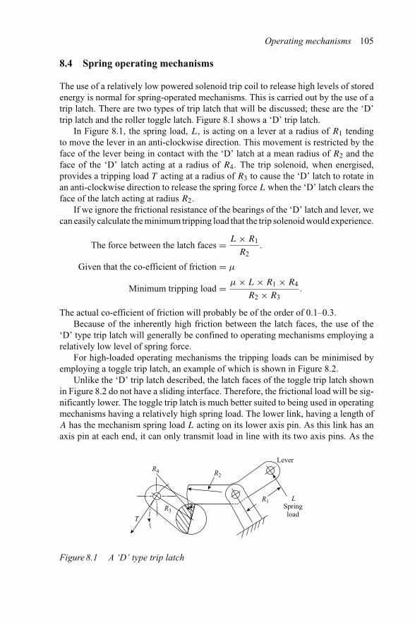
Operating mechanisms 105
8.4 Spring operating mechanisms
The use of a relatively low powered solenoid trip coil to release high levels of storedenergy is normal for spring-operated mechanisms. This is carried out by the use of atrip latch. There are two types of trip latch that will be discussed; these are the ‘D’trip latch and the roller toggle latch. Figure 8.1 shows a ‘D’ trip latch.
In Figure 8.1, the spring load, L, is acting on a lever at a radius of R1 tendingto move the lever in an anti-clockwise direction. This movement is restricted by theface of the lever being in contact with the ‘D’ latch at a mean radius of R2 and theface of the ‘D’ latch acting at a radius of R4. The trip solenoid, when energised,provides a tripping load T acting at a radius of R3 to cause the ‘D’ latch to rotate inan anti-clockwise direction to release the spring force L when the ‘D’ latch clears theface of the latch acting at radius R2.
If we ignore the frictional resistance of the bearings of the ‘D’ latch and lever, wecan easily calculate the minimum tripping load that the trip solenoid would experience.
The force between the latch faces = L × R1
R2.
Given that the co-efficient of friction = μ
Minimum tripping load = μ × L × R1 × R4
R2 × R3.
The actual co-efficient of friction will probably be of the order of 0.1–0.3.Because of the inherently high friction between the latch faces, the use of the
‘D’ type trip latch will generally be confined to operating mechanisms employing arelatively low level of spring force.
For high-loaded operating mechanisms the tripping loads can be minimised byemploying a toggle trip latch, an example of which is shown in Figure 8.2.
Unlike the ‘D’ trip latch described, the latch faces of the toggle trip latch shownin Figure 8.2 do not have a sliding interface. Therefore, the frictional load will be sig-nificantly lower. The toggle trip latch is much better suited to being used in operatingmechanisms having a relatively high spring load. The lower link, having a length ofA has the mechanism spring load L acting on its lower axis pin. As this link has anaxis pin at each end, it can only transmit load in line with its two axis pins. As the
T
R4
R3
R2
R1
Lever
LSpringload
Figure 8.1 A ‘D’ type trip latch

106 Distribution switchgear
Upper axis pin
T
LL
RL
L
t
Lower link
A
A
Figure 8.2 Toggle trip latch
upper axis pin is offset by the distance t , the latch roller will be maintained in contactwith the latch face by a component of spring force (see Figure 8.3).
The dimensions and the offset of the lower link are shown in Figure 8.3 on the left,and the resulting forces and their directions are shown on the right-hand side. Theforce acting on the latch face tL can be determined by applying the rules of similartriangles:
tL
L= t
A.
Therefore
tL = L × t
A.
Given that the co-efficient of the latch rolling friction is μr , the minimum trippingload required from the trip solenoid, T , can be determined from the dimensions ofthe latch levers and links shown in Figure 8.2.
T × LL = RL × μr × tL

Operating mechanisms 107
A L
t
tL
Figure 8.3 Dimensions and vectors of forces acting on the latch face
Therefore
T × LL = RL × μr × L × t
A
and
T = RL × μr × L × t
A.
The tripping load would, of course, be increased by the frictional resistance of thepin bearings and this should be taken into account.
As the latch roller is in contact with a latch face that has a constant radius of RL,it will maintain a constant latch load. The trip solenoid, not shown in Figure 8.2, actsby applying a tripping load of T at a radius of LL. Latch stability is provided by alight spring, not shown, acting in the opposite direction to the tripping load T . Inpractice, the latch roller would normally be arranged to have a case hardened activeface and, to minimise friction, it would also run on a needle roller bearing. In addition,some designers ensure that the left-hand latch component is dynamically balanced byarranging for the mass of latch metal to be equally spread on either side of its bearingso that a mechanical shock in any direction will not cause the latch to rotate. This isparticularly important when switchgear is to be located in an area that is subjected toseismic shock.
The hinge points shown as being fixed in Figure 8.2 may be arranged to be fixedonly when the operating mechanism is in a certain condition, for example, when it isreset, or when it is reset and its springs are charged.
A word of warning before leaving the subject of latches. As a general rule, thearmature of trip and electrical release solenoids should never be lubricated. Alwaysconsult the manufacturer’s product handbook. Numerous instances of failure to trip orfailure to close on electrical release have been caused by over-enthusiastic lubricationin the solenoid armature region, even though specific warnings against doing this weregiven by the manufacturer in the product handbook. The reason for the warnings is

108 Distribution switchgear
that, with time, the lubricating oil will dry out leaving a sticky residue which preventsthe solenoid armature operating.
8.5 Three-link kinematic chains
The closing force profile requirements of circuit breaker operating mechanisms issuch that a relatively low force will be required during the initial part of the con-tact stroke in order to give a smooth start to the acceleration of the moving parts.The operating mechanism must provide a relatively high force towards the end of theclosing stroke in order to overcome frictional drag of contact loading imposed by theelectrical contact system. These requirements are not compatible with the load char-acteristics provided by helical closing springs, which start very high and fall awayas the spring expands. A three-link kinematic chain is used to provide the operatingmechanism force required from a helical closing spring by selecting crank angles anddimensions in order to change the output load during the operating cycle. An exampleof this is shown in Figure 8.4.
The three-link kinematic chain shown in Figure 8.4 consists of a load input crankA a connecting link B and an output crank C. The relationship between both outputtorque and velocity ratio for the three-link kinematic chain illustrated is detailed inFigure 8.5.
The output crank is arranged to receive the drive thrust from link B at a relativelysmall radius. This will convert the high start spring load to a small start torque. It isalso arranged to act at a large radius at the end of the stroke, where the spring loadwill be at a minimum. The input crank is shown to have a start angle, α, of 50◦ and afinal angle of 10◦. This final angle leaves the driven end of link B with an offset of t
which is an almost in-line position, imparting a high output torque.Latch and three-link kinematic chain elements described earlier which are used
in typical spring-operated mechanisms can be found in Figure 8.6, which is a line
Position X
t �
�
Load input crank A
Connecting link
Output crank
B
C
� = Input angle
� = Output angle
Figure 8.4 A three-link kinematic chain [10]

Operating mechanisms 109
3.0
2.0
Vel
ocity
rat
io=
1.0
050 40 30 20 10 0
2.0
Tor
que
ratio
=In
put t
orqu
e
Out
put t
orqu
e
4.0
6.0
–10°
Δ� Δ�
Velocity
Torque
Input angle
Figure 8.5 Torque and velocity relationship of three-link kinematic chain [10]
Opening force
Close release solenoidLatch roller
Prop
Stop
Spri
ng c
harg
ing
forc
e
‘ON’
‘OFF’
A
B
C
E
F
G
E
FG
H
H
D
Clo
sing
Spri
ng
DC
Stop
A11
B11
B1
A1
Latch rollerProp
Trip solenoid
Figure 8.6 Line diagram of a spring mechanism having an electrical release [10]
diagram of the linkages within a mechanism having a trip coil for opening and anelectrical release solenoid for closing. It will be appreciated that the design of spring-operated mechanisms is an involved and complex operation. It will usually be foundthat the design operation is carried out by experienced specialists within a switchgearmanufacturing company, who will use historical data, established design elements,materials, surface finishes and hardness criteria that have been proven by service

110 Distribution switchgear
experience and time. In addition, extensive use of high-speed photography will bemade to examine all aspects of the mechanism’s performance in detail.
The dotted and chain dotted lines in Figure 8.6 indicate the link positions that aretaken up when a trip or close operation has been carried out. The solid lines show thepositions taken when the circuit breaker is closed and its springs have been charged.Examination of Figure 8.6 shows that clockwise rotation of crank H to its fixed stopposition will cause the closing spring to be charged, and the Close release solenoidlatch to be engaged. It will be noted that links F and G are arranged to be not quitein line. This toggle alignment imparts a thrust on the release coil latch roller so thatwhen the latch prop is rotated clockwise by the release solenoid the links F and Gwill collapse, releasing the closing spring energy and causing an operation to takeplace to the ON position. When in the ON position, a similar toggle alignment isformed by links A and B which causes a load to be impressed by the trip solenoidroller on to its prop face. This means that when in this condition, energisation ofthe trip solenoid will cause the links to collapse to the A1 and B1 positions andthe circuit breaker to move to the OPEN position. Also shown are link positionsA11 and B11 which are the positions that the trip linkage takes up if a trip signalis received when a closing operation is in progress, thus meeting the requirementfor a trip operation having preference over a close operation. Examination of all ofthe linkages shows examples of three-link kinematic chains to harness the springloads to the circuit breaker operation requirements. The physical embodiment of themechanism described is shown in Figure 8.7.
Pin attached toclosing spring
Figure 8.7 Physical arrangement of linkages in the mechanism describedabove [10]

Operating mechanisms 111
8.6 Magnetic actuators
Common sense, confirmed by numerous surveys including an extensive internationalsurvey by CIGRE in the 1980s, indicates that the more components there are that goto make up an assembly, the greater the potential for unreliability. This is particu-larly true when considering components that move, such as those found in operatingmechanisms. It follows, therefore, that if a new concept for an operating mechanismwas conceived which offered virtually only one moving part, it would be taken up invarious forms by a high proportion of switchgear manufacturers. This was the casewith the magnetic actuator. The principle of operation of the magnetic actuator canbest be described by reference to Figure 8.8 which shows the typical constructionfound in most magnetic actuators.
It can be seen that a typical magnetic actuator has a central armature housedwithin a magnetic yoke. This armature, when compelled, will move from the lowerposition shown in the diagram to its upper position, and then vice versa. The travelbeing defined by the space between the ends of the armature and the end walls ofthe magnetic yoke. Around a section the armature, and in close proximity, is a setof permanent magnets which are arranged to have poles laterally arranged acrosstheir shortest length. As shown in the diagram, the flux from these magnets links thearmature, the air gap and the magnetic yoke. While some magnetic actuators operateby using a single coil, Figure 8.8 is shown to be a two-coil arrangement. Thesecoils are wound so that, when energised, they will produce magnetic flux as shown inFigure 8.8 when starting in the OPEN position. It can be seen that this flux opposes theflux produced by the permanent magnets at the bottom end of the actuator, releasingthe magnetic hold that was in place, and augments the flux produced by the permanentmagnets across the air gap at the top of the actuator. If sufficient flux is produced,
Bearing
Armature
Magnetic fluxfrom coils
Magnetic fluxfrom permanentmagnets
Bearing
Magnetic yoke
Permanentmagnets
Coils
Drive to contact system
Figure 8.8 Typical construction of a magnetic actuator

112 Distribution switchgear
Figure 8.9 Cylindrical form of magnetic actuator (courtesy of ALSTOM T&D Ltd)
the armature will move to the upper or ON position and will be magnetically heldin this position when the operating coils are de-energised. When in the ON position,current passing through the coils in the reverse direction will, by similar action to thatdescribed for closing, cause the actuator to move to the OPEN position. Productionmagnetic actuators can be either cylindrical in form, or a flat rectangular box-likeform as shown in Figures 8.9 and 8.10.
In the 1960s, a low VA trip coil was patented by George F. Chrisp [11], whichwas mechanically charged and held in the charged position by permanent magnets. Inmany respects, this device can be said to have anticipated today’s magnetic actuator,but the energy it was able to release was limited by the strength of the magnets whichwere available at that time. However, considerable progress has been made in magnettechnology since that time and this has led to the widespread application of magneticactuators with vacuum interrupters in distribution switchgear. The vacuum interrupterbeing essentially a short stroke device as is magnetic actuator making them an idealcombination. The progress in magnet technology can be seen in Figure 8.11.
One of the attractions of the magnetic actuator is that it consumes no power whenthe circuit breaker is in the ON or OFF position. However, it must hold the contactsin either position with sufficient force to meet the operational requirements. Whilethe actuator is essentially a bi-stable ‘flip/flop’ device it must do more than that, inthat it must not only hold the contacts in the OFF position during normal operations,but it must also maintain them in that position when subjected to external shock loadswhich form part of its service site conditions. It must also hold its vacuum interruptersin the ON position with a force at least equal to the minimum external force specifiedby the vacuum interrupter manufacturer which is designed to allow the contact systemto safely carry its maximum rated peak and short time short-circuit current. In otherwords it must maintain a designed minimum hold-on load.
Typical minimum hold-on forces specified by vacuum interrupter manufacturersare given in Figure 8.12. However, when designing a magnetic actuator, informationrelating to the specific vacuum interrupter that is intended to be used must be obtained.

Operating mechanisms 113
Figure 8.10 Rectangular form of magnetic actuator (courtesy of MedelecSwitchgear Ltd)
The magnetic actuator must provide a hold-on force greater than the minimumspecified for three vacuum interrupters. This is because vacuum interrupters havebutt contacts which must have a maintained contact load in the closed position evenwhen the maximum contact erosion has taken place.
The principle of the interrupter drive arrangement is shown in Figure 8.13. Thisshows that the mechanism drive to the interrupter is by a linking element which pro-vides the final drive via a spring. This spring provides automatic compensation forboth contact wear and differences in contact alignment. As the lowest applied springload should be that recommended by the vacuum interrupter manufacturer, it followsthat the actual applied load will be at a maximum when the interrupters are new, withno contact erosion, and must be at least equal to the minimum recommended loadplus the spring rate multiplied by the erosion allowance.
As it is usual to drive all three interrupters with one magnetic actuator, theminimum hold-on force of the actuator will be equal to this new higher load.

114 Distribution switchgear
400
KJ/m3
300
200
Max
imum
ene
rgy
dens
ity (
BH
MA
X)
100
1900 1920
Steel
Alnico
Ferrite
SmCo5
Sm2Co17
NdFeB
1940 1960 1980 2000Year
Figure 8.11 Development of magnetic energy density in the twentieth century [12]
1000
10010 100
kgf
kA
Figure 8.12 Typical relationship between vacuum interrupter contact force andkA rating [13]
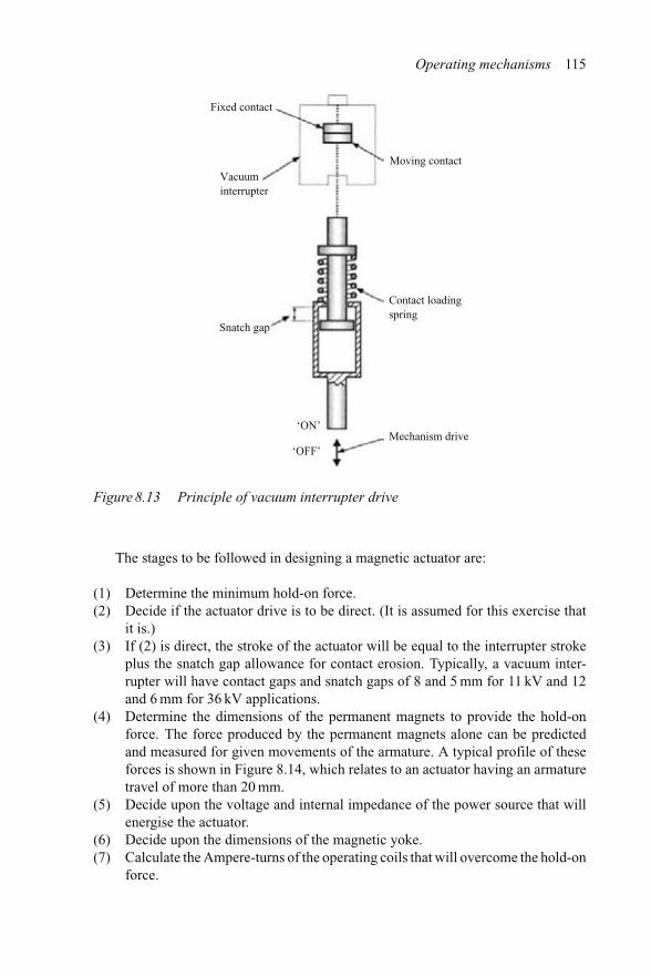
Operating mechanisms 115
Fixed contact
Vacuuminterrupter
Snatch gap
Contact loadingspring
Moving contact
Mechanism drive‘ON’
‘OFF’
Figure 8.13 Principle of vacuum interrupter drive
The stages to be followed in designing a magnetic actuator are:
(1) Determine the minimum hold-on force.(2) Decide if the actuator drive is to be direct. (It is assumed for this exercise that
it is.)(3) If (2) is direct, the stroke of the actuator will be equal to the interrupter stroke
plus the snatch gap allowance for contact erosion. Typically, a vacuum inter-rupter will have contact gaps and snatch gaps of 8 and 5 mm for 11 kV and 12and 6 mm for 36 kV applications.
(4) Determine the dimensions of the permanent magnets to provide the hold-onforce. The force produced by the permanent magnets alone can be predictedand measured for given movements of the armature. A typical profile of theseforces is shown in Figure 8.14, which relates to an actuator having an armaturetravel of more than 20 mm.
(5) Decide upon the voltage and internal impedance of the power source that willenergise the actuator.
(6) Decide upon the dimensions of the magnetic yoke.(7) Calculate the Ampere-turns of the operating coils that will overcome the hold-on
force.

116 Distribution switchgear
50000
–50000
40000
–40000
30000
–30000
1000020000
–20000–10000
Forc
e pe
r un
it le
ngth
(N
/m)
00 5 10 15 20
Position (mm)
Figure 8.14 Static armature force-stroke characteristic (courtesy of ALSTOMMedium Voltage Switchgear, South Africa)
2 – 0212e + 0002 – 5390e + 0002 – 2569e + 0001 – 9748e + 0001 – 6927e + 0001 – 4106e + 0001 – 1285e + 0008 – 4635e – 0015 – 5423e – 0012 – 0212e – 0011 – 4666e – 009
Mag B
y
x
Figure 8.15 Dynamic analysis of magnetic flux (courtesy of ALSTOM MediumVoltage Switchgear, South Africa)
This process may well be iterative and will need to be repeated for various degreesof actuator travel. However, there are specialist companies that can assist by producinga four-dimensional analysis (three physical dimensions plus time) that will indicatethe performance of the actuator modelled in real time. This will allow the designto be understood and refined to exactly match the operational requirements of theapplication. This, in turn, will have an important influence on the efficiency of theactuator design and also upon its cost, as the cost of the actuator is directly related tothe energy it can supply [5] (see Figure 8.15).

Operating mechanisms 117
Contacts closed
Closing coil current A B C D
Opening coil current Contacts closed
Contacts openContacts openOpening operationClosing operation
Figure 8.16 Closing and opening operation oscillograms
Having an efficient actuator of minimum cost will still leave a potential cost issuewith regard to its power source when applications such as stand-alone secondaryswitchgear equipment are concerned. This is because the power source is typicallyLithium batteries which can have a significant cost. Consider typical closing andopening records of such a device, which are shown in Figure 8.16.
It will be seen in the oscillograms shown in Figure 8.16 that both the closingcoil and opening coil currents show an initial rise in value and then a fall. Thisis due to the change in inductance that takes place as the armature of the actuatorchanges its position. Once the contacts complete their travel, shown as points A andC, the coil currents continue to rise until they attain their maximum value. Auxiliaryswitches driven by the main contacts will then interrupt the coil currents at points Band D. There are two disadvantages associated with using this method of coil currentinterruption.
(1) As the actuator is magnetically latched at each end of its travel, the passageof further current serves no operational purpose. The energy drawn from thebatteries after contact movement ceases is therefore wasted and the battery usedmust be much larger than would otherwise be necessary.
(2) If, for some reason, the current passing through the coils is reduced to a sub-operation level, coil burn-out could occur.
The use of a timing device in the coil energisation circuit would avoid the seconddisadvantage but would still involve the use of a larger battery than would otherwisebe necessary.
A means of detecting the second rise in coil current would minimise the size ofbattery needed, or alternatively, as patented by Johnson and Dilkes [14], proximityswitches incorporated within the actuator (and energised at the same time as the coils)would also allow much smaller batteries to be used.


Chapter 9
Primary switchgear
As the name implies, primary switchgear is the first stage in the process of conductingelectrical power from the grid to the end user. The importance of the strategic positionof a primary substation and its switchgear within the system means that the layout,design and operation must ensure maximum availability and reliability.
As the system impedance is lower at the primary substation than further into thenetwork, the fault level tends to be higher, usually between 25 and 50 kA.
Until the 1960s, primary switchgear was invariably of the oil type, with mostinstallations being very large by today’s standards. An example of the size and com-plexity of these substations can be seen in Figure 9.1, which shows a Ferguson Pailintype VRP, 33 kV, 13.1 kA substation installed in the Swansea area in 1930.
The scale of the switchboard in the photograph can be judged by the relative size ofthe figure in the foreground. This oil switchgear, which was equipped with duplicatebusbars, can be compared to its modern vacuum equivalent, shown in Figure 9.2. Themodern equipment is much less than half the size and has more than twice the shortcircuit rating of its predecessor.
Although the manufacture of oil switchgear in the UK has been discontinued infavour of non-oil types, there are still large numbers in use and, over the years, theyhave given good service.
While duplicate busbar schemes are still used by some industrial users and over-seas power generation companies, they are rarely specified for today’s primaryswitchgear. This is because insulation reliability has greatly improved with mod-ern moulding materials, and the cost of single busbar protection schemes has beenreduced by the use of the blocking features of microprocessor-based relays.
The substation arrangement of primary switchgear must be given careful con-sideration in order to provide continuity of supply in the event of a transformer orincomer switchgear fault. This is usually achieved by enhancing the application flexi-bility through a measure of equipment redundancy. Considerable flexibility of supplyin primary substations with single busbars is usually obtained by having the primarytransformers connected to busbars which can be coupled using a bus-section circuitbreaker, as the typical arrangement shown in Figure 9.3.

120 Distribution switchgear
Figure 9.1 A Ferguson Pailin type VRP circuit breaker installed in 1930 (courtesyof ALSTOM T&D Ltd)
Figure 9.2 Type WSB 33 kV duplicate busbar vacuum switchgear (courtesy ofALSTOM T&D Ltd)

Primary switchgear 121
Primarytransformers
Incomers
Feeder circuit breakers Bus-section unit
Figure 9.3 Primary substation with two transformers and a bus-section circuitbreaker
In the event of a fault in one of the primary transformers shown in Figure 9.3,supply could be restored to all of the outgoing feeder circuit breakers by opening theincoming circuit breaker and closing the bus-section unit. Withdrawable and inter-changeable circuit breakers would enhance availability in an emergency by enablingrapid replacement of a faulty circuit breaker.
9.1 Changes in technology
The changes that have taken place in all types of switchgear are the result of twoprincipal drivers. The first being active competition, and the second changes in spec-ifications. The former brings about change by encouraging manufacturers to investin R&D to achieve reductions in the cost and size of their switchgear, as well asincreasing the ratings and facilities that they can offer to customers. The latter is amandatory change which manufacturers must adopt.
Let us examine the R&D effort first. A large percentage of switchgear develop-ment costs is spent on equipment certification and a major authority for carrying outindependent short-circuit tests is the KEMA laboratories in the Netherlands. KEMAis independent of all manufacturers and has established an international reputation forthe quality of the proving tests it carries out in order to award a certificate of rating.As a result of this, many of the world’s leading manufacturers use KEMA as a certi-fying body. Assuming that the work carried out by the KEMA laboratories representsthe overall relative activity of manufacturers, then an analysis of the certificates thelaboratories have issued from 1985 to 1997, for switchgear in the range of 12–36 kV,will indicate the relative effort being made by manufacturers on different interruptingtechnologies. Such an analysis is shown in Figure 9.4.
Figure 9.4 shows the number of certificates issued by the KEMA laboratories [5]plotted vertically, for vacuum and SF6 types of interrupter, against the years plottedhorizontally. It will be seen that the ratio of vacuum to SF6 certificates is about 10:1.

122 Distribution switchgear
0
5
10
15
20
25
30
35
40
45
85 86 87 88 89 90 91 92 93 94 95 96 97
VacuumSF6
Figure 9.4 Analysis of 12 kV to 36 kV KEMA circuit breaker certificates [18]
Figure 9.5 The evolution of 20 kA vacuum interrupters through the 1960s, 1970s,1980s and 1990s (courtesy of ALSTOM T&D) [18]
Clearly manufacturers have been putting considerably more effort into the devel-opment of vacuum interrupter-type switchgear than into SF6. The reason for thisis that manufacturers have been, and still are, making considerable progress withthe design and manufacturing technology of vacuum interrupters and the associatedcircuit breaker components. Having said that, it is important when making this com-parison to distinguish between switchgear which uses SF6 for insulating purposes andswitchgear which also uses the gas for interrupting purposes. The former, known asGIS form, is gaining a significant share of the available market. A striking exampleof the results of continuous development can be seen in the advances that have beenmade in vacuum interrupter technology. Figure 9.5 shows the progressive reduction

Primary switchgear 123
in the size of vacuum interrupters for a given rating that has taken place over the lastfour decades.
The dramatic reduction in size that can be seen is the direct result of investment inR&D, and mirrors the overall reduction in switchgear size seen in Figures 9.1 and 9.2.
9.2 Current and voltage transformers
Important peripherals, such as current transformers (CTs) and voltage transformers(VTs) have also seen radical design changes as a result of the work done to introduceepoxy and polyurethane moulding materials.
Ring-type current transformers have been used for many years in the UK-manufactured equipment and are now being introduced into switchgear manufacturedon the continent. The reason for this can be found in the relative cost ratio of the two,which is between three and five in favour of ring-type current transformers. Ring-type current transformers can be readily clamped to resin-insulated bushings withinthe current transformer chamber, as the surface of the moulded insulation on the pri-mary conductor can be given an earth layer by using silver loaded paint or hot metalliczinc spray. Similarly, this system can be used to prevent electrical discharge betweenelectrically stressed insulation and its surrounding metal enclosure. Figure 9.6 showsa modern voltage transformer cast in polyurethane with a metalised surface.
Figure 9.6 Moulded interior of a 12 kV voltage transformer (courtesy of ALSTOMT&D Ltd)
124 Distribution switchgear
The three vertical projections that can be seen in Figure 9.6 are housings forhigh-voltage VT fuse-links. The value of using high-voltage fuse-links to protect thevoltage transformer must be questioned. The lowest high-voltage fuse rating that canbe produced is 3.15 A. It is known that, under ferro-resonance conditions, a current ofbetween 400 and 600 mA will flow and cause the voltage transformer to fail; the fuse,therefore, provides no protection under these conditions. The argument for fittingVT fuses is that anything fitted to high-voltage equipment must be protected. Thecounter-argument is that protection is already provided by the circuit breaker andthat the fuse itself, and its accommodation, may actually cause problems in service.It is known that continental switchgear manufacturers do not normally fit VT fusesand the latest published edition of the Electricity Association Standard, EATS41-36,allows the user to choose whether or not to fit VT fuses.
Alternatives to conventional current and voltage transformers, using (1)Ragowski, (2) Hall effect and (3) capacitive devices hold out the promise of desirablefeatures for the switchgear designer, allowing greater freedom in the architecture thatcan be chosen, but to date, these devices have not made appreciable inroads into themarket. The reason for this may be due to user conservatism or a lack of enthusiasmbecause of the need for additional electronic signal amplifiers.
9.3 The architecture of primary switchgear
There are many possible ways in which the essential components of primaryswitchgear, that is, the busbars, circuit breaker, cable boxes and means of earthing,together with protection and instrumentation, can be arranged. Switchgear design-ers have used their ingenuity to arrive at arrangements which offer the user certainfeatures that are considered to be advantageous in terms of increasing the avail-ability of their primary switchgear. The following examples illustrate some of thesefeatures.
9.3.1 Horizontal transfer earthing
The way in which the essential components are arranged within switchgear employingvertical isolation and earthing, with horizontal transfer between the functions is shownin Figure 9.7.
The circuit breaker element is mounted on wheels and includes a vertical rackingmechanism. The diagram shows the circuit breaker in the raised position, linkingthe busbars and cable. The dotted lines show the circuit breaker in the busbar earthand the cable earth positions. It should be noted that when in either of these twopositions, automatic trip protection is disabled. Interlocking must be provided toprevent the circuit breaker closing or opening unless in a fully engaged or fullyisolated position.
A photograph of typical vertically isolated horizontally withdrawn switchgearis shown in Figure 9.8. This form of switchgear was prevalent in the UK and UK-influenced markets for many years. Originally incorporating oil circuit breakers, some

Primary switchgear 125
Busbar earthcontact
Instrument chamber
Busbar chamber
Current transformer chamber
Bushings
Cable earthcontact
Cable
Cable boxBushings
Operatingmechanism
Interrupter
Figure 9.7 Arrangement of components within vertically isolated switchgear
types, such as that shown above, survived by conversion to vacuum interrupters inair. The advantages of this type of switchgear include:
(a) The need for a separate earthing device and associated interlocks is obviated.(b) The position of the circuit breaker, in either the isolated or the engaged posi-
tion, is obvious. Similarly the position with regards to the busbar earth, theservice position, or the cable earth position can be readily seen when enteringthe substation.
9.3.2 Horizontal isolation with separate earthing switches
Separating the functions of fault current interruption and earthing, by the use ofseparate devices, was common practice within Continental Europe and is currentlywidely employed in the UK. A typical diagram of the internal architecture of this typeof switchgear is shown in Figure 9.9.
It will be seen in the diagram shown in Figure 9.9 that the circuit breaker is awheeled structure with primary isolating contacts arranged to engage with contactswithin a fixed housing. A separate cable earthing switch is located within the fixedhousing. Not shown in the diagram are the earthed shutters that would normallycover the fixed primary isolating contacts when the circuit breaker is moved out ofengagement. Also not shown is the interlock system, which would prevent the earth-ing switch being operated with the circuit breaker in engagement. Busbar earthing

126 Distribution switchgear
Figure 9.8 Type VMX vertically isolated horizontally withdrawn switchgear(courtesy of ALSTOM T&D Ltd)
normally requires another earthing switch to be fitted, but some users will accept thedeliberate removal of this interlock, to allow the busbars to be earthed through thecircuit breaker when the earth switch is in the closed position. Under these conditions,automatic protection tripping of the circuit breaker would be disabled.
As with all isolatable switchgear, interlocks are also provided to prevent opera-tion unless the circuit breaker is fully engaged or isolated. The isolation distance isspecified as the distance which will withstand electrical breakdown when impressedwith 115 per cent of the equipment’s rated impulse voltage. Standards also requirethat the withdrawable portion of the equipment remains connected to earth potentialuntil this the isolating distance is reached. A photograph of a circuit breaker of thistype is shown in Figure 9.10.
9.3.3 Horizontal isolation with internal earthing via vertical transfer
Switchgear employing horizontal isolation with vertical transfer for internal earthingvia the circuit breaker is very similar to the horizontal transfer switchgear describedearlier and shown in Figures 9.9 and 9.10.

Primary switchgear 127
Instrument chamber
Primary isolating contacts
Busbar chamber
Cable box
Cable
Cable earth switchCircuit breaker
Figure 9.9 Horizontally isolated circuit breaker with separate earth switch
Figure 9.10 Horizontally isolated circuit breakers having separate earth switches;type HWX (courtesy of ALSTOM T&D Ltd)

128 Distribution switchgear
In this version, the circuit breaker element is carried on a truck which incorporatesa screw jack for raising and lowering the circuit breaker. When inserted in the fullyraised position, the circuit breaker can be used to earth the busbars; in the central posi-tion, the circuit breaker links the cable to the busbars and in the lower position, it can beused to earth the cable. The three vertical transfer positions are shown in Figure 9.11.
The advantages of this arrangement are:
(1) No earth switches are required for earthing the busbars or cable.(2) The position of the circuit breaker in either the busbar earth, service or cable
earth positions is obvious to the operator.
The disadvantage of the arrangement, from the manufacturers’ point of view ratherthan that of the user, is that the expense of equipping every circuit breaker with rackingequipment to earth the busbars has to be met. This facility is not required on morethan, say, two circuit breakers on any one switchboard. A switchboard of this type,nearing completion in the factory, is shown in Figure 9.12.
It can be seen that there are two ports at the bottom of the front sheet of eachcircuit breaker. One of these is for horizontal insertion and withdrawal of the circuitbreaker, and the other is for vertical positioning in either the busbar earth, service orcircuit earth positions. The method of pre-selection and indication of these positionswithin the fixed housing is shown in Figure 9.13. It will be noted that, for operationalsecurity, facilities are provided to padlock the selector in any one of the three positions.
Instrument chamber
Primary isolating contacts
Busbar chamber
Cable box
Cable
Circuit breaker
Circuit breaker truck andraising/lowering mechanism
Figure 9.11 A horizontally isolated circuit breaker with earthing via verticaltransfer

Primary switchgear 129
Figure 9.12 Type MV12 switchgear, horizontally isolated with earthing via verticaltransfer (courtesy of Medelec Switchgear Ltd Malta)
Figure 9.13 Pre-selector of circuit breaker position; type MV12 switchgear(courtesy of Medelec Switchgear Ltd Malta)

130 Distribution switchgear
9.3.4 Horizontal isolation with internal earthing via top contactstem rotation
The final form of primary switchgear earthing to be described is one that is uniqueand has been used successfully for many years. This one again uses the circuit breakerto apply the earth, but does so by rotation of the circuit breaker top connector stemsso that they engage with earth contacts within the fixed housing. A diagram of thisarrangement is shown in Figure 9.14. A photograph of this type of switchgear isshown in Figure 9.15.
The ingenuity of switchgear designers is always being challenged to bring advan-tages that will make their product more attractive to the user. It was recognised thatthe overall size of switchgear together with the space required for installation is ofimportance to the user, as the total cost is a function of substation size. Switchgeardesigners studied three areas where it was considered that space could be saved. Thefirst was the space occupied by a circuit breaker when it was isolated from its primaryconnections, particularly if this was to be carried out behind a closed cubicle door.The second was the space necessary for withdrawal of the circuit breaker from thecubicle and the third was the space at the rear of the switchgear to give access forconnecting the power cables. One such design was produced which made large con-tributions to savings in all three areas. This was the VISAX, produced by ALSTOMT&D Ltd which is shown in Figures 9.16 and 9.17.
Cable
Cable box
Busbar chamber
Instrument chamber
Rotating primaryisolating contacts
Circuit breaker
Circuit breaker truck
Figure 9.14 Elements of a circuit breaker having horizontal isolation with cableearthing via top isolating contact stem rotation

Primary switchgear 131
Figure 9.15 Type SVB5 switchgear having horizontal isolation with cable earthingvia top isolating contact stem rotation (courtesy of ALSTOM MediumVoltage Switchgear, South Africa)
Rotatable circuit breaker module
Rear wall of substation
Isolating contacts
Operating mechanism
Current transformers
Cable earth switch
Rear vent chamber for internal arc products
Power cables
Figure 9.16 The type VISAX circuit breaker. Isolation by circuit breaker rotation(courtesy of ALSTOM T&D Ltd)
It will be seen in Figure 9.16 that the designer has provided access for making-offthe power cables via the front of the unit, allowing the rear of the unit to be closeto the substation wall and so saving space within the substation. In addition, thecircuit breaker module, shown in Figure 9.17, has been designed to rotate through

132 Distribution switchgear
Figure 9.17 The type VISAX rotatable circuit breaker module (courtesy of ALSTOMT&D Ltd)
90◦ to provide isolation. Each phase post houses a vacuum interrupter, with isolatingcontacts at each end. The isolation of the circuit breaker takes place behind a closedfront door. While this is not a specified requirement, it clearly will help to contributeto operator safety. The circuit breaker module incorporates runners, enabling it to bedismounted in the space provided for manual access.
The cable, circuit breaker and busbar chambers are arranged vertically, one abovethe other. This has allowed the designer to include a duct at the rear of the unit forventing of each chamber in the event of an internal arcing fault. The vent covers ofeach chamber are designed to prevent contamination from a faulted chamber enteringan unfaulted chamber.
9.3.5 Gas-insulated primary switchgear
The SF6 design technology developed for extra-high-voltage switchgear migratedwith time down to medium voltage switchgear in the range up to 36 kV to provide thebenefits that accrue from its use. These include size reduction, immunity from atmo-spheric contamination and also introduce the concept of maintenance-free switchgear.Figure 9.2, which shows a 33 kV duplicate busbar switchboard, the ALSTOM typeWSB, serves to illustrate the dramatic savings in space that switchgear of this typecan provide.
For simplicity and flexibility of production, switchgear of this type is manu-factured in the form of modules that can be assembled in various configurations tomeet the specific requirements of customers. This can be single or duplicate busbarunits, bus couplers, bus section units, incoming feeder, outgoing feeder, units having

Primary switchgear 133
A Vacuum circuit breaker and mechanism.
BI Busbar chamber No.1
BII Busbar chamber No.2
C Sub-frame and cable chamber
D Low-voltage chamber
Figure 9.18 Type WSB 33 kV gas insulated switchgear (courtesy of ALSTOMT&D Ltd)
voltage transformer accommodation and so on. A diagram showing how a duplicatebusbar GIS unit can be made up from individual modules is shown in Figure 9.18.
Gas-insulated switchgear has found favour in applications where space is at a pre-mium or where the environment is particularly harsh, either because of high humidity,high salt levels, or where there is the possibility of dangerous industrial gases beingpresent.
The switchgear designer has to make a careful choice with regard to the materialsto be used within SF6 gas. The gas is very dry and can change the mechanical char-acteristics of certain plastics that have a relatively high moisture content. It is alsoimportant that the switchgear is designed and proven to be discharge free internally.Even the smallest measure of discharge would cumulatively create dangerous acidsthat could lead to internal electrical failure.


Chapter 10
Cable connected secondary switchgear
It is the function of cable connected secondary switchgear to accept electrical powerfrom a primary switchboard (see Chapter 9). The secondary switchgear then dis-tributes the power to points in the network where the voltage is either transformed toa lower value or where it is consumed without transformation, as would be the casewhen supplying high-voltage machines.
There are basically two types of application. The first is that used to providepower to housing developments and small industrial estates and the second is withinthe local network of relatively large consumers. In the first type of application, atypical network used is the ring-main as shown in Figure 10.1.
33 kV/11 kVprimarysubstation Primary busbars
Normally open pointRing circuit
Figure 10.1 A typical ring-main network for secondary distribution

136 Distribution switchgear
Within the typical distribution network shown, there are two primary incomingsupplies, feeding the ring-main via two incoming circuit breakers and a normally openbus-section unit in the primary switchboard. The network is shown to be operatingwith one switch at the remote end open in the ring circuit. This means that each sideof the ring will run as a radial feeder. This arrangement helps with fault location,reduces the number of consumers who would lose their supply in the event of afault, giving the system greater flexibility and increased availability. In the eventof a permanent fault occurring in one of the primary incomer circuits, the primaryincoming circuit breaker would be opened/isolated and the bus-section circuit breakerclosed to re-establish supplies to all consumers fed by the ring-main. Should a faultoccur in any of the interconnecting cables, the ring switch on either side of the faultedsection can be opened and the ring switch which was in the open position can beclosed to re-establish supplies to all consumers. Repairs to the faulted cable sectioncan then be carried out in safety with the ring switch at either end of the faulted cableopened and in the earthed position. Facilities must be provided to allow any cablerepair to be tested before it is returned to service. Because of the large capacitancecurrent taken by the cable, any a.c. voltage test sets would have to be very large, so itis normal practice to use a d.c. high-voltage test set for this purpose. The test voltagesgenerally used for distribution cables and switchgear are shown in Table 10.1.
Figure 10.1 shows eight secondary substations being fed by the ring-main circuit,and in practice, up to a maximum of about 20 such substations can be supplied inthis way. If we look in more detail at each secondary substation, we will see that theyare all identical and have a common group of components (see Figure 10.2).
It was realised that as the same arrangement of distribution voltage switchingfunctions was used at each T-off point, savings could be made by specifying factorybuilt units that incorporated all of these functions within one standard unit. As willbe seen in Figure 10.2, the combined functions that were incorporated into the newconcept of ring-main unit, known universally as an RMU, were two ring switches,each having three positions of ON, OFF and EARTH, and a T-off switch to controlthe transformer, which was initially a high-voltage fuse-switch and later a circuit
Table 10.1 D.c. test voltages used for cables and switchgear
System rated 15 min d.c. test voltagevoltage (kV)
New cables Existing cables and switchgear
Phase–earth Phase–phase Phase–earth Phase–phase(kV) (kV) (kV) (kV)
7.2 15 21 11 1812 25 34 18 3036 66 – 60 –

Secondary switchgear 137
Ring circuitTransformer
Ring-main unit
T-off switch andearth switch
T-off circuit breakeror HV fuse
Low voltage cabinet
Load break/faultmake ring switch
Figure 10.2 Basic elements of a secondary ring-main substation
Figure 10.3 A Schneider electric-type ringmaster SF6 ring-main unit [15]
breaker, together with a low rated transformer earthing switch. The ring switcheswere fitted with interlocked access covers to allow cable test plugs to be fitted tocheck the adjacent ring cable for possible faults.
The concept of the RMU originated in the UK but, because of the cost savingsthat they gave the user, the design and manufacture of RMUs was quickly takenup by manufacturers in many countries across the world. A typical modern outdoorring-main unit is shown in Figure 10.3.
138 Distribution switchgear
In addition to the direct cost savings associated with the use of a standard ring-main, additional benefits included:
(1) The purchaser could make an accurate direct comparison of prices betweensuppliers because of a standard specification.
(2) RMUs do not require a large R&D input when compared to circuit breakers. Forexample, the ring switches are usually of the plain break moving contact type,and the T-off circuit was originally almost exclusively controlled by high-voltagefuses. See the switching technology section of this chapter. These relatively basiclevels of technology were readily available to a large number of manufacturers,allowing a greater number to compete, which had the effect of driving downthe market price. In more recent times, the availability of low-cost, low ratedvacuum interrupters and the development of rotating arc SF6 interrupters haveallowed larger transformers to be controlled although with a greater R&D effortand a marginal increase in unit costs.
(3) Site costs and space components required for interconnecting separate switchingwere saved.
The T-off connection between the ring-main unit is specified to be via a standarddimensional flange, which also has standard dimensioned electrical bushings. Thisgives the user interchangeability between various ring-main units as well as allowingconnection to the associated power transformer either directly, or via a cable.
There were attempts to integrate further by including the distribution transformerin the same unit but these were unsuccessful. This was mainly due to the manymanufacturers involved in combining components usually manufactured on differentsites with these components requiring different manufacturing lead times. However,most manufacturers offer the equivalent to a skid mounted assembly of a ring-mainunit, a transformer and low-voltage distribution cabinet (see Figure 10.4).
Although most distribution companies choose to directly couple the transformerand ring-main unit, some distribution companies prefer to mount each element ofthe secondary substation separately, using cables to connect them together. This is toallow for relatively easy replacement of individual elements. An example of this isshown in Figure 10.5.
The substation shown in Figure 10.5 is of the outdoor type. While substations ofthis type can minimise first cost, the equipment used has to be specified to have a highdegree of environmental protection, typically IP54, with all ferrous parts being zincplated. Even with this degree of protection, some problems can occur due to wateringress through seals that have to be made on site. The upper surface of the ring-mainunit and its T-off cable box in Figure 10.5 can be seen to be suffering from the effectsof the environment. The outdoor substation is also prone to external damage causedby vandals. The disadvantages of the outdoor open-type substation are overcomeby the use of compact substations, housed within a cubicle that is factory built. Anexample of one of these is shown in Figure 10.6.
Figure 10.6 shows a secondary packaged substation with the HV and LV accessdoors open. Such arrangements offer the power distributor a small substation sizewith minimum installation work, together with good operator access. Visual impact

Secondary switchgear 139
Figure 10.4 Secondary substation with directly mounted ring-main unit (courtesyof Schneider Electric Ltd)
Figure 10.5 Secondary substation with cable connected elements (photo: author)

140 Distribution switchgear
Figure 10.6 Cubicle packaged secondary substation (courtesy of SchneiderElectric Ltd)
Figure 10.7 Factory assembly of a part underground package substation (courtesyof ALSTOM Medium Voltage Switchgear, South Africa)
is becoming an important issue and, in order to minimise this impact, some manufac-turers offer substation packages for installation either completely underground, or asshown in Figure 10.7, partially underground.
There are manufacturers who go to great lengths to offer equipment that willreduce the visual impact of substations. They do this using glass reinforced cement tomanufacture the housings and applying an external finish that mimics other buildingsin the area. These mimic the appearance of brick, stone and in extreme cases, evenwooden log cabin-like constructions, as shown in Figure 10.8.
Returning to ring-main circuit applications. Some supply authorities, particularlythose in southern Australia, have achieved even greater flexibility and availability by
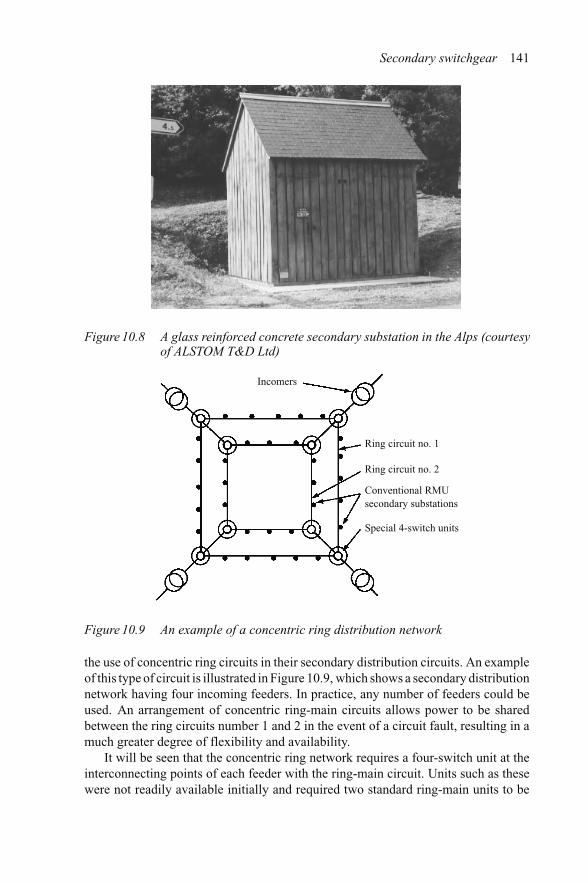
Secondary switchgear 141
Figure 10.8 A glass reinforced concrete secondary substation in the Alps (courtesyof ALSTOM T&D Ltd)
Incomers
Ring circuit no. 1
Ring circuit no. 2
Conventional RMUsecondary substations
Special 4-switch units
Figure 10.9 An example of a concentric ring distribution network
the use of concentric ring circuits in their secondary distribution circuits. An exampleof this type of circuit is illustrated in Figure 10.9, which shows a secondary distributionnetwork having four incoming feeders. In practice, any number of feeders could beused. An arrangement of concentric ring-main circuits allows power to be sharedbetween the ring circuits number 1 and 2 in the event of a circuit fault, resulting in amuch greater degree of flexibility and availability.
It will be seen that the concentric ring network requires a four-switch unit at theinterconnecting points of each feeder with the ring-main circuit. Units such as thesewere not readily available initially and required two standard ring-main units to be

142 Distribution switchgear
Wiringbox Busbar
jointing
End cap
Door
Door
453
Ringcable box
SSEVRE
6110
72
1477
1925
Protectioncover
EFJ mountingbracket
Ringcable box
Figure 10.10 Sabre extensible outdoor secondary switchgear (courtesy of W. Lucy& Co. Ltd)
coupled together. However, continental manufacturers later developed four-switchunits for applications such as these, but these new units were for indoor, or cubi-cle applications only. Within the United Kingdom, some manufacturers introducedextensible outdoor switchgear that would meet the requirements for concentric ring-main distribution schemes. A modern example of this type of switchgear is shown inFigure 10.10.
Some industrial users, particularly those involved in quarrying, have within theirinternal distribution system a need for two power transformers at each secondarysubstation. A number of these users saw that if a ring-main unit could be connectedas a circuit spur via its T-off, cost savings could be realised by using one ring-main unitto control two power transformers via its ring switches, as shown in Figure 10.11.The users recognised that the T-off earth needed to be padlocked into the closedposition as it only had a limited short-circuit rating. They also recognised that a faultin any transformer would result in both transformers losing their supply. However,for them this solution offered cost savings with an acceptable loss of flexibility andavailability.
10.1 T-off circuit protection
The problem associated with the supply of power for the protection devices controllingthe T-off circuit, which in turn supplies power to the distribution transformer, is that itis not readily available without the additional expense of a low-voltage supply. In thisrespect, it is very similar to the problems that needed to be resolved for the overheadline secondary switchgear (see Chapter 9).

Secondary switchgear 143
Low-voltage chambers
Power transfomers
Reverse fedconventional ring-mainunit
Radial spur cableconnection
Figure 10.11 Reverse fed ring-main unit controlling two power transformers
T-off primary conductor
Time-fuse link
Protection current transformer
Shunt trip coil
Figure 10.12 Time-fuse tripping circuit
Initially, when high-voltage fuse-links were used, the problem was resolved byfitting the fuse links with a small chemical charge which would trip all three phasesin the event of any one fuse operating (see Chapter 12). With the introduction ofcircuit breakers for T-off control, they required an operating command to be given bythe protection in order to trip under fault conditions. One of the ways of resolving thisproblem was to fit current transformers to the T-off bushings and arrange for each ofthese to be shunted by a special low-voltage fuse link, known as a time-fuse link. Inthe event that the current from the protection current transformer causes the time-fuseto operate, the output from the current transformer is automatically passed on to ashunt trip coil, which will operate to open the circuit breaker (see Figure 10.12).

144 Distribution switchgear
Several factors have to be taken into account when selecting the rating of thetime-fuse. These include:
(1) Catering for 150 per cent over-rating of the transformer, as allowed under thecode of practice.
(2) The transformer inrush current, when being energised.(3) Discrimination with the low-voltage fuses within the distribution cabinet.(4) No tripping due to spillage current from the time-fuse circuit.
We examine each of these in turn using an 11 kV, 500 kVA transformer as an example.
10.1.1 150 per cent transformer over-rating
The normal full load current is given by the expression:
Ifl = kVA rating√3 × voltage rating
Given that the kVA rating is 500 and the voltage rating is 11 kV, the full load currentwill be:
Ifl = 500√3 × 11
= 26.24 A
The 150 per cent over-rating current will, therefore, be
Istr = 150 × 26.24
100= 39.36 A
10.1.2 The transformer inrush current
The heating, or I 2t , of the transformer inrush current is conveniently taken as beingequivalent to ten times the transformer full load current for 0.1 of a second. In otherwords, a point on the time current characteristic which should be less than that whichwould cause deterioration of controlling high voltage or time-fuse.
For a 500 kVA transformer, this would be 10×26.24 A, which gives the equivalentof 262.4 A at 0.1 s on the fuse operating characteristic.
10.1.3 Discrimination with fuses on the low-voltage side
Because of the distribution of fault current from the LV side of a transformer to the HVside, an inter-phase fault on the low-voltage side of the distribution transformer givesthe most onerous condition in that this results in a fault current equal to 0.866 timesits symmetrical fault current. The corresponding currents in the three phases on thehigh-voltage side of a Delta/Star connected distribution transformer are in the ratio of2 : 1 : 1, the maximum being equal to the high-voltage side three-phase fault current

Secondary switchgear 145
as against 0.866 times the symmetrical fault current on the low-voltage side. Giventhat the fault impedance of the distribution transformer is typically 5 per cent, andassuming that a factor of 0.6 is used to take into account the low-voltage impedance ofthe fault. The fault current which will flow on the high-voltage side will be equal to:
100 × 0.6√3 × 5
= 6.93 times the rated high-voltage current.
which, for a 500 kVA, 11 kV transformer:
= 26.24 × 6.93
= 181 A.
Given the protection current transformer ratio, and the distribution transformer ratio,the current on the secondary side can be determined. This latter ratio is equal to thevoltage ratio multiplied by 0.866. For example, a 11 kV to 415 V transformer willhave a transformation ratio of
= 11,000 × 0.866
415= 22.95.
With this information, the operating time for the low-voltage fuse can be comparedwith the operating time of the protection time-fuse to determine compatibility.
10.1.4 No tripping due to spillage current from the time-fuse circuit
Care has to be taken to ensure that under maximum fault conditions, the impedanceof the time-fuse circuit is not such that spillage current from this circuit be sufficientto operate the circuit breaker trip coil. To this end, the time-fuse circuit, completewith fuse should be tested under voltage and current conditions which are consideredto be typical with regard to waveshape, with a magnitude equal to or greater than thatwhich would be found in service.
Standardisation of the protection current transformer ratio has been introducedand these ratios together with time-fuse ratings are shown in Table 10.2, which followsthe time-fuse characteristics.
10.2 Time-fuse operating characteristics
Figure 10.13 shows time-fuse characteristics that have become standard withinthe UK.
It will be seen that not all of the time-fuses shown in Figure 10.13 are includedin Table 10.2. Those not shown are intended for use with non-standard transformerratios and non-standard protection CT ratios.

146 Distribution switchgear
Current (A)1 2 3 4 5 6 7 8 910 20 30 40 50 60708090100 200 300 400 500
0.01
0.02
0.03
0.04
0.050.060.070.080.090.1
0.2
0.3
0.4
0.50.60.70.80.91.0
2
3
4
56789
10
20
30
405060708090
100 1 2 3 4 5 6 7 8 9 10 20 30 40 50 60708090100 200 300 400 500
3A5A
7.5A10A
12.5A15A
Per-
arci
ng ti
me
(s)
Figure 10.13 English Electric time-fuse operating characteristics (courtesy ofALSTOM T&D Ltd)
10.3 The Falcon protection scheme
The Falcon ring-main unit was the first SF6 ring-main unit having a circuit breaker tocontrol the T-off circuit and was introduced by Hawker Siddeley in the early 1980s.

Secondary switchgear 147
Table 10.2 Protection CT ratios and time-fuse ratings
Transformer Protection Time-fuse rating (A)CT ratio
Voltage (kV) kVA rating
11 315 50/5 511 500 50/5 1011 800 100/5 7.511 1000 100/5 10
6.6 315 50/5 106.6 500 100/5 7.56.6 800 100/5 12.5
T-off primary conductor
Low VA shunt trip coil
Bi-metal switch
Protection current transformer
Figure 10.14 The Falcon type protection
The design philosophy that was adopted was that no fuses, either high-voltage or time-fuses would be used as these would have to be stocked and carried by operationalpersonnel, which was considered by the designers to be undesirable to the potentialusers. A means had, therefore, to be found to detect fault conditions and to tripthe T-off circuit breaker when pre-set limits were reached, without any low-voltagesupply being available. In addition, this protection had to be sufficiently flexible tobe applied to the protection of a wide range of distribution transformers.
The solution, which was arrived at and patented by Hawker Siddeley, was similarto that used in the time-fuse system but with the time-fuse replaced by a bi-metalswitch, which was supplied by very small current transformers. These current trans-formers had cores that were designed to saturate and, in conjunction with a rangeof bi-metal element switches, produce a family of protection curves which meet thecriteria set out for the time-fuse type protection. Figure 10.14 illustrates the protectionarrangement.

148 Distribution switchgear
As the current transformers used in the Falcon protection scheme were relativelysmall, the power output for tripping the T-off circuit breaker was also very small.This meant that a low VA trip coil had to be used with a rectifier interposed betweenit and the bi-metal switch.
10.4 Protection where a low-voltage source is available
The provision of a low-voltage source local to secondary switchgear is relativelyexpensive, but in certain circumstances it can be considered to be essential. Suchcircumstances include applications requiring facilities for remote measurement, oper-ation and control. The benefits of these facilities include a reduction in the numberof customer minutes lost in the event of a system fault; one of the criteria by whichthe efficiency of local electrical distribution companies is judged. However, once alocal low-voltage electrical supply is available, more sophisticated protection andcontrol equipment may be employed. An example of a remote terminal unit, knownas an RTU, for communication between the ring-main unit and its control centre formonitoring conditions at the site, is shown in Figure 10.15.
10.5 Secondary distribution switchboards
In large customer networks, there is a need for secondary distribution switchboards.These switchboards take their power from the network via the supplier’s primaryincoming switchboard. Secondary switchgear used for these distribution applicationsusually has lower fault and normal current ratings and less flexibility than switchgearused for primary distribution, and in addition, it may have reduced dimensions. For
Figure 10.15 A Talus 200E remote terminal unit for secondary distribution(courtesy of Schneider Electric)

Secondary switchgear 149
example, the switchgear used in secondary distribution switchboards will usually notbe suitable for applications requiring duplicate busbars and quite often the circuitbreakers will be of the fixed type as opposed to the withdrawable type most commonin primary distribution switchgear. However, as these switchboards are normally ofthe multi-panel type, they will usually be provided with a low-voltage power source,permitting more sophisticated measurement, protection and control than would nor-mally be found in ring-main units. The circuit breaking elements of these units areoften derived from those that were developed for secondary overhead line and ring-main unit distribution applications. This can be seen in both the size and ratings ofvacuum interrupters and in SF6 interrupters. An example of this with SF6 interrupterscan be seen in Figure 10.16(a) and (b).
(a)
(b)
Figure 10.16 a The interrupter enclosure of the Ringmaster RMU [3]b A sectional view of the GENIE circuit breaker (courtesy of
Schneider Electric)

150 Distribution switchgear
(a)
(b)
(c)
Figure 10.17 a A Ringmaster extensible switchboard (courtesy of SchneiderElectric)
b Indoor secondary switchgear within a cubicle for outdoor appli-cation (courtesy of ALSTOM Medium Voltage Switchgear,South Africa)
c Type VISAX ‘S’ fixed vacuum switchgear (courtesy ofALSTOM T&D Ltd)

Secondary switchgear 151
Most manufacturers produce secondary distribution switchgear using either vac-uum or SF6 interrupting technology. The primary insulation systems can be air, SF6gas, or SF6 gas with solid insulation as shown in Figure 10.16(b).
The design of the switchgear can be of the indoor or outdoor type, or even indoordesign within a cubicle type housing for outdoor applications. An example of anoutdoor switchboard is shown in Figure 10.17(a). Examples of some of the othertypes are shown in Figure 10.17(b) and (c).


Chapter 11
Overhead conductor connected secondaryswitchgear
11.1 Introduction
Because of the relatively high cost of electrical distribution by buried cable, powersupplies to sparsely populated areas are invariably provided by overhead line con-ductors. The present-day overhead line distribution equipment is the product ofinnovation and evolution resulting from many years of application in the field ofrural electrical distribution. Advances in technology, as they have become avail-able, have been adopted to provide better security and continuity of the supply ofpower to remote centres of consumption, as well as providing the power supplierwith information which was not readily available a few years ago.
11.2 Standards
The basic standard for autoreclosers is ANSI C37.60. This standard was modifiedwhen vacuum interrupters were introduced to recognise the longer contact life of thenew technology. The standard requires many more fault operations with vacuum thanwith oil, recognising the inherent longer life of vacuum interrupters.
The only other known standard for autoreclosers is the UK EATS41-26, whichaccepts the ANSI standard but adds to it the IEC values for transient recovery voltageas well as introducing a three second short time current fault rating and internal arcfault requirements.
11.3 Historical background
Electrical power supplies to remote consumers are invariably provided by radial over-head line feeders with pole mounted transformers at the consumer’s end to provide a

154 Distribution switchgear
Source circuitbreaker
145/11 kVtransformer Overhead network
Figure 11.1 A typical early rural network with source circuit breaker only
low-voltage supply. The voltage of the overhead line from the source to the consumer’stransformer can be anything from, typically, 3.3 to 38 kV.
The earliest systems consisted of a source transformer supplied at a voltagebetween 66 and 145 kV, which stepped this voltage down to 3.3 to 38 kV, and suppliedthe overhead line via a source circuit breaker (see Figure 11.1).
When a fault on the line caused the source circuit breaker to trip, all consumerswould lose their electrical power, and a patrol would set out on foot to find and repairthe fault. Experience showed that on many occasions no fault could be found, as thefault was transient in nature, caused by birds, lightning, wind blown foliage andthe like, which meant that the source circuit breaker could be successfully reclosed,re-establishing power to the consumers. Human nature, being what it is, meant thatoperators would ‘test’ the line by closing the source circuit breaker before decidingto set out to find the fault, and in more than 50 per cent of the cases, supply wassuccessfully restored without line inspection being necessary. This was extended bythe operators attempting a second closure of the source circuit breaker, should thefirst attempt result in a trip operation. This was found to result in about another25–30 per cent successful re-establishments of supply. It was correctly deduced thatmost faults on overhead power lines were transient in their nature, the fault beingself-cleared when the electrical power was removed.
In the early 1930s, it was decided that the immediate need was for a new operatingmechanism on the source circuit breaker which would automatically reclose the circuitbreaker three times when it tripped out on a fault (see Figure 11.2).
This technique reduced the time necessary to restore supplies to customers whena transient fault appeared on the system. The application was successful in that powerwas restored when interruptions were caused by transient faults, but all customerslost power for a short period regardless of where the fault occurred within the system.
11.4 Pole mounted autoreclosers
It was realised that if a circuit breaker, preferably pole mounted, could be installedon the overhead line some distance into the network to automatically open andreclose in the event of a fault, the disadvantage of all customers losing their electricalpower whenever a fault appeared would be overcome, by avoiding the interruptionof supply to customers connected upstream from the breaker. The problem facing

Overhead conductor 155
Figure 11.2 An early source circuit breaker fitted with a four shot to lock-outmechanism, circa 1931 (courtesy ALSTOM T&D Ltd)
the switchgear designer in producing such a device was how to provide the oper-ating mechanism energy. It was found that this operating energy could be providedby a weight suspended from the operating mechanism to recharge the mechanismsprings. Autoreclosers having this type of operating mechanism were then producedand installed. They brought a significant improvement to the system in terms of whatis today called ‘customer minutes lost’ as customers upstream from the autoreclosersaw no interruption in supply and customers downstream from the autorecloser sawonly a short interruption if the fault was transient in nature. The disadvantage ofthis arrangement was that for practical height reasons energy for only six operationscould be stored before the weight reached its bottom limit, which required a visitfrom an operator to haul the weight back to its top position. Statistics showed that apole mounted autorecloser installed on an average length overhead line in an averagearea would operate up to 138 times in a year. Weight operating mechanisms, whilebringing improvements to the system, still involved considerable manual interven-tion to keep them operational, requiring 20–30 visits to site per year per unit, tohaul the weight back to its top position. An autorecloser of this type is shown inFigure 11.3.
It was an American, by the name of Kyle, who, in 1956, introduced the useof power from the overhead line itself to recharge the mechanism springs. He didthis by including an HV solenoid within the autorecloser tank that was automaticallyconnected to the overhead line each time the unit was opened, until a pre-set number ofoperations in a given time had been reached. A schematic for this type of unit is shownin Figure 11.4. This shows that the power supply for the HV solenoid is provided

156 Distribution switchgear
Figure 11.3 A weight operated pole mounted autorecloser (courtesy of ALSTOMT&D Ltd)
Main contactsPhase conductors
HV solenoid
Auxiliary switches
Autorecloser tank
Figure 11.4 Schematic of an autorecloser operated by an internal HV solenoid
by electrical connections between two phases on the supply side of the autorecloser.The supply is controlled by two auxiliary switches that are automatically closed whenthe main contacts move to the open position, thus connecting the HV solenoid to thesupply voltage and causing the unit to close. Not shown in the schematic is another

Overhead conductor 157
pair of series connected auxiliary switches which, when opened, will isolate theHV solenoid leaving the autorecloser in the ‘locked out’ condition. These additionalauxiliary switches are operated by a device that causes them to operate when a pre-setnumber of operations occur within a defined period of time.
11.5 Technical terms
Before discussing the application of these and subsequent units on a distributionsystem, it is necessary to appreciate the meaning of a number of special technicalterms, which are in addition to those applied to normal circuit breakers:
Dead timeThis is the elapsed time from the cessation of current flow to its re-establishment.
Shots to lock-outThe pre-set number of fault trip operations before lock-out.
Lock-outThe open condition reached by an autorecloser when it has completed its pre-setnumber of shots to lock-out. Manual local or remote intervention will be necessaryto close the unit.
Delayed tripA trip operation with a time delay inversely proportional to the magnitude of the faultcurrent.
Instantaneous tripA trip operation which is performed without any built-in time delay.
SequenceThe pre-set trip operations within the shots to lock-out. These will be either delayed(D) or instantaneous (I) trip operations. The most commonly specified sequence was2I 2D. The reasoning behind this was that the two instantaneous trips would clear anytransient system faults, and after those operations the fault, if it was still present, wasdeemed to be permanent and the delayed operation was to allow sufficient energy topass through downstream fuses to clear the fault (see Figure 11.5).
Reclaim timeThe time taken by the autorecloser’s protection to reset to the beginning of its pre-setsequence should the fault be cleared before lock-out is reached.
It will be seen in the upper part of Figure 11.5 that the transient fault current, repre-sented by a relatively thick line, causes the autorecloser to trip on an instantaneoussetting. On the subsequent reclosure, the fault is still present, causing the autorecloserto again trip, this time on its second instantaneous setting.
On the third reclosure, the transient fault has cleared, the autorecloser remainsclosed and the protection resets in readiness for any subsequent fault. In this case, alldownstream customers have their power supply restored.
The lower part of Figure 11.5 shows the sequence of events when a permanentfault occurs on a system having an autorecloser and downstream high-voltage fuses.

158 Distribution switchgear
Normal load current
Fault initiatedFault current
Normal current supply resumed tounfaulted network
Time
Time
Closed
Open
Fault cleared
Fault cleared bydownstream fuse
Transient fault cleared by the second instantaneous autorecloser trip
Permanent fault cleared by a downstream fuse during second delay trip
Figure 11.5 Autorecloser sequences when clearing transient and permanent faults
The fault causes the autorecloser to carry out its two instantaneous trip operationsand then, as the fault is still present, initiate its delayed trip sequence in order toallow sufficient fault current to flow to cause the downstream high-voltage fuses tooperate and clear the fault. The autorecloser remains closed and its protection resetsin readiness for any subsequent fault. In this case, all customers downstream of thehigh-voltage fuses will lose power until repairs are carried out, and all other customerswill have their power restored.
11.6 Discussion on autoreclosers with HV internal solenoidmechanisms
While the introduction of autoreclosers with internal HV solenoids brought animprovement in the continuity and reliability of the supply of power to rural con-sumers, they also made life difficult for the manufacturers. This was because of anatural law associated with solenoid operation, which limits the voltage range towhich they can be applied. This range is about ±10 per cent. Too low an appliedvoltage would result in prolonged coil energisation, leading to burn out, bursting, andinternal fault. Too high a voltage would cause mechanical damage to the mechanism.As the actual specified system voltage can be anything between 3.3 and 38 kV, it meantthat an individual customer’s system voltage had to be identified at an early stagein a contract, and, therefore, manufacture for stock was not practical. It also meantthat routine test equipment within the factory before dispatch had to be sufficiently

Overhead conductor 159
flexible to cope with the operation of the units at all system voltages, as these testschecked the operation of the autoreclosers on their pre-set sequences at the specifiedsystem voltage. It also meant that customers needed a high-voltage test cage withintheir maintenance depots to check new units on arrival and units which were beingmaintained. Finally, because of the electrical connections of the internal high-voltagesolenoid, the autoreclosers could only operate with the power source in one direction,effectively limiting their application to radial connected overhead lines effectivelyprecluding ring circuit applications.
11.7 Hydraulic control
Until about 1980, most autoreclosers used hydraulics to control the type of trip opera-tion, I or D, and the reclaim time of the protection. Phase fault trip operations were viaseries connected coils, which were relatively small solenoid coils within the autore-closer, one per phase, and were connected in series with the main current circuit ofthe overhead line. The series coil assembly included hydraulic dashpots connected toarmatures located within each solenoid. In the event of a system fault, the armaturewould be attracted into the solenoid by the passage of fault current. For instanta-neous trip operations, a port in the side of the dashpot would be opened, and fordelayed operations the port would be closed, bringing the dashpot into action. It willbe appreciated that each current rating would need its own size of series connectedcoil, in order to maintain constant ampere turns, further limiting the locations on thesystem where the autorecloser could be installed without internal modification. Theselection of I and D trip operations and the number of shots to lock-out could only beadjusted by the position of drive pins within the operating mechanism, making suchchanges practically impossible in the field. The reclaim time for the protection couldnot be adjusted, as this was set by a dashpot that had to be manufactured to a veryhigh accuracy to obtain limits of 60–120 s. It should be noted that time control usinghydraulic means would vary with temperature due to changes in oil viscosity, whichcould lead to protection discrimination problems.
The dead time of the autorecloser was determined by the natural spring chargingtime for the operating mechanism, typically 1 s. Later models were provided witha mechanism drive point adjustment which could double the dead time. No otherdead times could be selected. Despite all of these disadvantages, units of this typewere successful because of the benefits they provided. It is interesting to note thatthe identified requirement for earth fault protection was met by using three currenttransformers and a spring loaded relay. Current transformers were not normally usedfor phase fault protection until electronic control relays were introduced in the 1980s.
11.8 The short-circuit fault level of overhead lines
Because of the relatively high impedance of overhead lines, there is a rapid fall offin fault level with the line length from the transformer source. For example, a 14 kAfault level at the source will be reduced to only 4 kA at about 4 km from that source.

160 Distribution switchgear
14
12
10
8
6
4
2
00 5 10 15 20 25
Linemm2 Al/Fe
152/25
106/25
106/25152/25
Distance from feeding transformer (km)
kA(rms)TransformerMVA32
32
1616
Figure 11.6 Fall-off of fault level with line length on a 13.8 kV system [16]
This is illustrated in Figure 11.6 which gives values for a 13.8 kV system. Asoverhead lines can be 100 km long, the fault level at the mid-point will be very low.For this reason, 5 kA was a typical standard rating for an oil autorecloser.
11.9 Advances in interrupter technology
In the early 1980s ‘sealed for life’ autoreclosers using SF6 rotating arc interrupterswere introduced which eliminated the three-year maintenance requirement of the oilinterrupter autoreclosers. The contact drive system of a unit of this type is shown inFigure 11.7. A more detailed explanation of the way in which rotating arc interruptersfunction is given in Chapter 2. In many ways, the drive system for an autorecloserusing rotating arc SF6 for interruption is very similar to the oil interruption types andshares the common loss of flexibility in application with regards to the direction ofpower supply.
However, there were two fundamental advantages offered by this new design.The first was that during fault current interruption, the rotating arc SF6 interrupterdid not impose any significant back-pressure on the contact system, thus reducingtotal mechanism energy necessary for operation. Secondly, and more importantly,for the first time, a unit requiring no contact maintenance was being offered. Themany advantages of using SF6 for both interruption and insulation are detailed inChapter 2. However, there were two significant problems that caused some delay inthe subsequent rapid acceptance of this type of unit. The first was the customers’

Overhead conductor 161
Main contacts
Insulating link
Latch
Opening springs
High-voltagesolenoid
Interruptercoil
Figure 11.7 The type PMR unit. An SF6 rotating arc autorecloser [17]
need to gain confidence in gas tightness and the second, which was shared by all SF6switchgear, was concern about end of life disposal.
At about the same time as the SF6 autoreclosers were being introduced, the Kyleplant in the USA introduced oil immersed vacuum interrupter autoreclosers. Both theSF6 rotating arc and vacuum interrupter types of units were capable of operating atfault levels up to 16 kA. This made them very attractive to customers for use withinthe system and also, because of their ratings, as pole mounted source circuit breakersin place of the much more expensive conventional ground mounted circuit breakers.
11.10 Sectionalisers
Overhead line sectionalisers are fault make/load break switching devices which aredesigned to automatically open during the dead-time of an associated upstream autore-closer, in order to remove a faulted section of the line and allow the power supplyto be restored to the remainder. Sectionalisers operate by counting the number ofpulses of fault current within a specified period of time and only opening when thepassage of fault current ceases. The settings are adjustable to allow up to three pulsesof fault current to pass before operation. These pulses of current can be of very shortduration, such as would be the case if the autorecloser was set for instantaneous tripoperations. Therefore, sectionalisers extend the benefits of autoreclosing further intothe network. A diagram illustrating the co-ordination between a sectionaliser, set fortwo current pulses to trip, and its upstream autorecloser is shown in Figure 11.8.

162 Distribution switchgear
Fault current
Normal current
Time
Time
Closed
Open
Closed
Open
Permanent fault cleared by a downstream sectionaliser
Autorecloser
Sectionaliser opensduring autorecloserdead time
Sectionaliser
Figure 11.8 Autorecloser and sectionaliser co-ordination
As sectionalisers can be fitted with earth fault protection, they can detect andhelp to remove earth faults with currents as low as 4 A. High-voltage fuses, on theother hand, cannot detect these low currents and, therefore, do not have the samefunctionality. As sectionalisers are only load-break units, and the energy for openingtheir contacts is stored in springs within the unit, there is a potential for danger.They are the only load-break devices in distribution systems that are held closed by amechanism latch. Manufacturers of sectionalisers recognise that the integrity of thelatch is of the utmost importance as it would be catastrophic if, during the passage offault current, the latch were to be released by shock or vibration.
Examples of typical single-phase and three-phase sectionalisers are shown inFigure 11.9(a)–(c).
There is another type of sectionaliser available that is known as an ‘automaticsectionalising link’. These are factory-sealed devices that are a direct fitting replace-ment for distribution type expulsion fuses. They consist of a sealed single metal tube,which acts as a Faraday cage, enclosing an electronics package. Surrounding the tubeis a small current transformer that inputs data to the electronics relating to the currentflow. If the threshold of operating current is exceeded, that is when fault current flows,the electronics will count this as fault number one.
If the fault is transient in nature and is cleared by the associated upstream autore-closer, the electronics will reset to zero. However, if the fault current resumes whenthe autorecloser closes, the electronics, if factory set for two pulses to lock out, willwait for the fault current to cease for the second time, and then send an ignition currentto a chemical striker pin. This, in turn, causes the automatic sectioning link to dropout to the ‘open’ position. These links can be arranged to cause all three phases toopen if one phase operates. The device is shown in Figure 11.10.
The automatic sectionalising link has the distinct advantage over more conven-tional sectionalisers in terms of cost, but the current transformers are too small to

Overhead conductor 163
(c)
(a) (b)
Figure 11.9 Examples of sectionaliser unitsa Single-phase type GH 14.4 kV, 140 Ab Type GN3E 14.4 kV, 200 A, andc Type GN3VE 24.9 kV 200 A with electronic control(courtesy of Cooper Power Systems)
be residually connected so they have the disadvantage of not being able to see andoperate on earth fault currents.
As autoreclosers can be used in series, both of the above types of sectionalisersowe their existence to their relatively low unit cost when compared with the unit costof an autorecloser.
11.11 Protection
At about the time that the new interrupting technologies were being introduced, workwas being carried out to produce a microprocessor protection relay to control all ofthe functions that were currently being carried out by hydraulic means. There wereseveral objectives to carrying out this work. The first was to reduce the mechanical
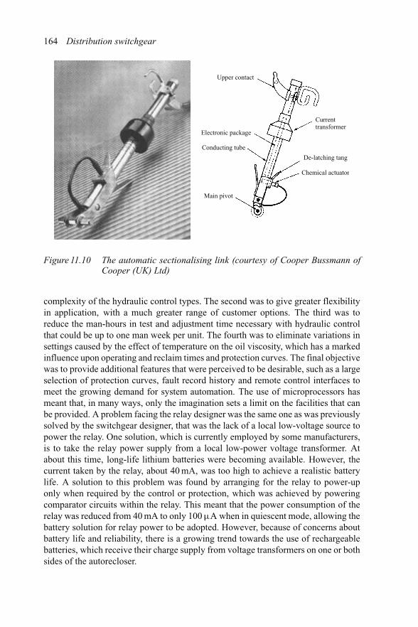
164 Distribution switchgear
Upper contact
Electronic package
Currenttransformer
De-latching tang
Chemical actuator
Conducting tube
Main pivot
Figure 11.10 The automatic sectionalising link (courtesy of Cooper Bussmann ofCooper (UK) Ltd)
complexity of the hydraulic control types. The second was to give greater flexibilityin application, with a much greater range of customer options. The third was toreduce the man-hours in test and adjustment time necessary with hydraulic controlthat could be up to one man week per unit. The fourth was to eliminate variations insettings caused by the effect of temperature on the oil viscosity, which has a markedinfluence upon operating and reclaim times and protection curves. The final objectivewas to provide additional features that were perceived to be desirable, such as a largeselection of protection curves, fault record history and remote control interfaces tomeet the growing demand for system automation. The use of microprocessors hasmeant that, in many ways, only the imagination sets a limit on the facilities that canbe provided. A problem facing the relay designer was the same one as was previouslysolved by the switchgear designer, that was the lack of a local low-voltage source topower the relay. One solution, which is currently employed by some manufacturers,is to take the relay power supply from a local low-power voltage transformer. Atabout this time, long-life lithium batteries were becoming available. However, thecurrent taken by the relay, about 40 mA, was too high to achieve a realistic batterylife. A solution to this problem was found by arranging for the relay to power-uponly when required by the control or protection, which was achieved by poweringcomparator circuits within the relay. This meant that the power consumption of therelay was reduced from 40 mA to only 100 μA when in quiescent mode, allowing thebattery solution for relay power to be adopted. However, because of concerns aboutbattery life and reliability, there is a growing trend towards the use of rechargeablebatteries, which receive their charge supply from voltage transformers on one or bothsides of the autorecloser.

Overhead conductor 165
11.12 Magnetic actuators and their impact onthe design of autoreclosers
Up to this stage, the progress of autorecloser development had reached the pointwhere ratings had increased to those of source breakers, but they still took powerfrom the overhead line for operation. Therefore, although they had established elec-tronic control and protection relays with their own independent lithium battery supply,the problem of dependence upon power from the overhead line for operation stillremained. The relatively low operating energy requirements for vacuum interrupters,together with the advent of new rare earth permanent magnets, allowed switchgeardesigners to examine an idea for a mechanism drive, based upon the switching ofmagnetic flux. Chapter 8 discusses the design of magnetic actuators in greater depth,but to gain an understanding of the principle of their operation, see Figure 11.11.
The assembly shown in Figure 11.11 is a magnetic actuator in its simplest form. Ithas a single moving part, the central armature. This armature has a ring of permanentmagnets assembled within the fixed structure at the mid-point of the armature. Aboveand below the permanent magnets are two coils. When the upper coil is energised,the magnetic flux that it produces assists the permanent magnet flux in the air gapabove the armature, and opposes the permanent magnet flux which is holding thearmature in the lower position. The value of flux density is chosen to be such thatthe armature will be attracted to the upper position and will then be held there by thepermanent magnets when the coil is de-energised. The reverse occurs when the lowercoil is energised. The design is therefore inherently bi-stable. The combination ofmagnetic actuator and vacuum interrupters resulted in a mechanically simple device,and opened up the opportunity for autoreclosers having lithium battery operation,thus regaining the independence from the overhead line for operation that was lostwhen the high-voltage solenoid was introduced.
The advantages for the user of magnetic actuator mechanisms include the flexibil-ity of application at any system voltage up to the rated voltage without modification,and the possibility to operate with power sources in either direction relative to the
Drivebeam
Coils
Permanentmagnets
Armature
Magnetic fieldfrom coils
Magnetic fieldfrom permanentmagnets
Figure 11.11 Schematic diagram of a magnetic actuator

166 Distribution switchgear
autorecloser’s orientation. The magnetic actuator also gave the advantage of obviatingthe need for a central high-voltage test cage to check autorecloser operation.
For the manufacturer, the advantages were that in addition to mechanical sim-plicity, it was no longer necessary to manufacture units to specific customer systemvoltages. This meant that units no longer had to be manufactured in small batchrequirements, and that in-house operational checks could be carried out without theneed for a high-voltage test cage. However, the advantages for both the customer andmanufacturer did not end there. As unit operation was, once again, independent ofthe overhead line, the direction of the power source relative to the autorecloser didnot matter, giving considerable flexibility in application.
11.13 Remote monitoring and operation
There is a growing demand for remote monitoring and operation of autoreclosers.Remote monitoring gives the supply authority knowledge of the state of the network;which switching units are closed or open, the current flowing, without having towait for notification of a problem from the public before taking corrective action.Remote operation provides the opportunity to reconfigure the network in order torestore supplies as soon as possible in the event of a permanent system fault.
11.14 Islands of intelligence
This system, which was devised by power supply companies on the north eastseaboard of the USA, provides automatic network reconfiguration without the use ofradio or any manual intervention or inter-unit communication other than the passageof fault current. It is known as a closed loop system. A diagram of this type of systemis shown in Figure 11.12.
R.NCR.NCR.NC
R.NC
R.NO
Fault
Supply B
Supply A
R.NCR.NC
R.NC = Normally closed autorecloser R.NO = Normally open autorecloser
Figure 11.12 Diagram of a closed loop system

Overhead conductor 167
Consider Figure 11.12. It can be seen that the system consisted of two radialfeeders, A and B, each having three autoreclosers. Another autorecloser, normallyopen, is connected between the two lines at their remote ends. Each autorecloserhad voltage detection on each side. It can be seen that if a permanent fault occurredbeyond the first autorecloser on line B, the second autorecloser on this line woulddetect loss of voltage on one side and would itself open when a pre-set time wasreached. The normally open tie autorecloser would also detect loss of voltage on oneside and would close when its own pre-set time was reached, re-establishing supplyto part of line B by back-feeding from line A. This is a simplified version of an actualsystem, which was a little more complicated in reality. The advantage of the closedloop system is that it does not rely on radio communications and is relatively fast inreconnecting customers. However, the system still relies upon customers who losetheir supply notifying the power authority that there has been a fault on the line.The overhead line powered autoreclosers, which were used in this application couldonly accept power from one side, and had to be modified to include a low-voltagesolenoid fed from external voltage transformers on each side, which made the schemerelatively very expensive.
As the operation of autoreclosers with magnetic actuators is independent fromthe overhead line, units of this type are ideal for closed loop application and anyother application where system reconfiguration may require the direction of powersupply to be reversed. Several manufacturers, including Cooper Power, The JoslynHi-Voltage Corporation, FKI and ALSTOM, offer autoreclosers powered by magneticactuators. An example of the FKI unit is shown in Figure 11.13. This unit relies uponSF6 gas for insulation, which has given excellent service but may be perceived to bea potential source of problems in the event of a gas leak from one of the gaskets thatform part of its assembly. The issue of end-of-life disposal may also be of concern.
In order to avoid possible customer concerns over gas or oil leaks and end-of-lifedisposal, some manufacturers have introduced autoreclosers that use solid insulationand avoid the use of oil and SF6 gas. Examples of these autoreclosers and their controlunits are shown in Figures 11.14 and 11.15.
The Joslyn TriMod™ Type 300 series autorecloser has ratings of up to 29.3 kV,800 A and 16 kA. It houses a vacuum interrupter in each phase which has an aluminiumouter body filled with a patented solid foam insulation. The unit uses an otherwiseconventional vertical porcelain insulator and a removable polymer horizontal insu-lator. This latter insulator facilitates access for the removal of the phase currenttransformer.
The Kyle® Type Nova™ autorecloser is rated for use up to 38 kV, 800 A, 12.5 kAand consists of three solid polymer insulated interrupter modules, an encapsulatedcurrent transformer and an aluminium mechanism housing. It utilises state-of-the-art vacuum interrupters encapsulated in environmentally inert cycloaliphatic epoxyresin mouldings. The Nova cycloaliphatic epoxy is an outdoor polymer mixed withhardener and filler. This proprietary formulation is said to be superior in areas ofsurface tracking, hydrophobicity, ultraviolet light and physical properties.
The Kyle® Form 6 microprocessor-based relay (see Figure 11.15(a)) provides pro-tective functionality and simple interactive graphical interfaces. Metering functions
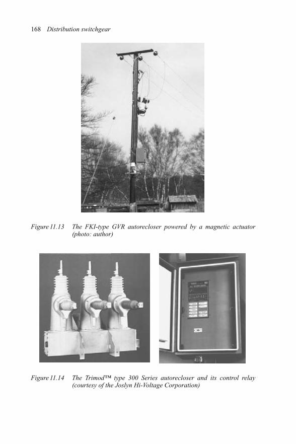
168 Distribution switchgear
Figure 11.13 The FKI-type GVR autorecloser powered by a magnetic actuator(photo: author)
Figure 11.14 The Trimod™ type 300 Series autorecloser and its control relay(courtesy of the Joslyn Hi-Voltage Corporation)

Overhead conductor 169
(a) (b)
(c)
Figure 11.15 The Kyle® type Nova™ autorecloser and control relays (courtesy ofCooper Power Systems)
include demand and instantaneous current for each phase. Symmetrical componentsfor both voltage and current are displayed along with kilowatt-hours for energymetering, second and 15th harmonics monitoring are also included.
The Kyle® Form 5 microprocessor-based autorecloser control (seeFigure 11.15(b)), provides the intelligence to supervise an attached autorecloser. Thecontrol is also equipped with serial ports to interface with communication equip-ment. The control provides instantaneous and demand metering with programmable

170 Distribution switchgear
integration intervals for the following functions: real and apparent power in eachphase, power factor, voltage and current in each phase as well as positive and negativesequence voltages, and positive, negative and zero sequence currents.
As was stated earlier, the use of microprocessors has meant that, in many ways,only the imagination sets a limit on the facilities that can be provided. Switchgearmanufacturers, particularly those offering autoreclosers with solid insulation, areaware of the possible trade-off involved in using this insulation to avoid the use of oil orSF6 gas. It is realised that solid insulation does not have the self-healing properties ofoil or SF6 gas in the event of voltage induced breakdown. The design, therefore, has toprevent electrical discharge on, or within, the insulation when subjected to excessivesystem voltage excursions, otherwise some permanent damage to the insulation willoccur. If this is allowed to happen, further system voltage excursions may lead toaccumulated damage and eventual insulation failure.
11.15 Autoreclosers with integral series disconnectors
Recently, a market demand for a new type of autorecloser was identified. The require-ment was for an autorecloser incorporating a series disconnector within its assemblyto provide a high-impulse voltage withstand when in the OPEN position. This wasconsidered to be desirable because users had identified that an autorecloser witha built-in series disconnector would save them from having to purchase, install andmaintain a separate open structured air-insulated disconnector. It also guaranteed safeoperation because of electrical and mechanical interlocking between the autorecloserand its disconnector. An example of one of the first autoreclosers of this type, thetype VPR, is shown in Figure 11.16.
The type VPR autorecloser uses specially developed vacuum interrupters, whichare driven by a magnetic actuator within a stainless steel enclosure. While the unitcontains SF6 gas for insulation purposes, there are no gaskets involved in sealing inthe gas. All joints are welded, including the bushing flange tank interface. In addition,drives into the unit are via welded stainless steel bellows.
The drive for integral disconnectors within the VPR autorecloser is manual only,via an external drive shaft (see Figure 11.17).
As the disconnector is an off-load switching device, the design of the contactdrive mechanism is very important in terms of the contact make and break sequenceof operation in relation to that of the main contacts. It has to be arranged that during theclosing operation of the disconnector, its contacts are driven to the fully home positionbefore the vacuum interrupter contacts close to complete the electrical circuit. Thismust, of course, allow for any pre-arcing. Similarly, during an opening operation, thevacuum interrupter contacts must open and clear the circuit before the disconnectorcontacts start to separate. This is achieved within the type VPR autorecloser by a camdrive to the disconnector, which is in effect a lost motion drive device.
The alternative VPR control relays are shown in Figure 11.18.The two types of control relay are used with the VPR autorecloser are shown
above. The relay shown in Figure 11.18(a) was designed to include the necessary

Overhead conductor 171
Figure 11.16 A type VPR autorecloser with integral disconnectors and surgearrestors during installation (courtesy of ALSTOM T&D Ltd)
Magnetic actuator
Cam drive
Disconnector
Vacuum interrupter
Interrupter drive
Figure 11.17 Arrangement of internal disconnector drive of the type VPR autore-closer (courtesy of ALSTOM T&D Ltd)
interfaces for remote control and monitoring, while Figure 11.18(b) is intended forlocal control applications. Both relays offer similar features, such as fault protection,current measuring and fault history, as described earlier for similar units.
11.16 A summary of the development of autoreclosers
Table 11.1 gives a summary of the chronological development of autoreclosers interms of the order in which features were introduced.

172 Distribution switchgear
(a) (b)
Figure 11.18 The alternative microprocessor-based control relays VPR unit(courtesy of ALSTOM T&D Ltd)
Table 11.1 Chronological development of autoreclosers
Operating power Potential energy of external weight �High voltage solenoid � � �Magnetic actuator and lithium batteries � � �Magnetic actuator and rechargeable leadacid batteries
� �
Primary internalinsulation
Oil � � �SF6 � � �Solid �
Arc control Arc control pot � �Rotating arc SF6 �Vacuum � � � �
Protection Hydraulic � � �Micro-electronic � � � � �
Series disconnector �
time →
11.17 Significant trends
There are four recent trends that are believed to be very significant in the field ofautoreclosers. These are as follows:
(1) The application of remote control and automatic operation to pole mountedequipment is expected to increase, in order to maximise the continuity of supplyby real-time reconfiguration of the network.

Overhead conductor 173
(2) Some manufacturers believe that there will be a customer preference for non-oil,non-SF6 autoreclosers. If this belief proves to be the case, then units of this typewill capture a greater market share. However, this share may be influenced by theintroduction of designs, such as the stainless steel all welded SF6 autoreclosers,which address the concerns regarding possible insulation leaks.
(3) Many users have identified that an autorecloser with built-in series disconnectorwill save them from having to purchase, install and maintain a separate openstructured air-insulated disconnector. The first autorecloser of this type wasproduced by ALSTOM and the current model is known as the type VPR. Theremay be a growing customer preference for composite units of this type.
(4) Autoreclosers owe their existence to the need to detect and clear transient faults,and these transient faults can be avoided by using overhead cable instead ofbare overhead conductors, which obviated the need for autoreclosers. Overheadcables have been used in Japan for at least the last 20 years and in Scandinavia forthe last decade. At least two Regional Electricity Companies, RECs, in the UKhave installed elements of overhead cable in their networks. It is the policy ofone REC to use overhead cable for the main radial feeder, and in order to reducecosts, only use bare overhead conductors on spur lines. It is at these connectingpoints that they are installing autoreclosers with integral series disconnectors,to give a point of isolation. If this trend grows, the effect will be to reduce thenormal and short-circuit current ratings of autoreclosers that will be required.This is because the installation point for autoreclosers will only be at spurs fromthe main radial feeder within the network, at the intersection of overhead cablesand bare conductors, and will usually be some distance from the line incomer,which means that the impedance of the overhead cable will significantly reducethe fault level.

Chapter 12
High-voltage fuse-links
High-voltage current limiting fuse-links are widely used for the protection ofdistribution cables and transformers. They commonly form part of fuse-switch com-bination units, or in some cases they are used as stand-alone devices to provide thesole protection of equipment. Their particular advantages are their low first cost, theirsmall dimensions and their ability to limit the peak fault current and let-through energyof a short-circuit fault to a small fraction of the prospective value. Well-designed fuse-links can limit the fault energy to around one 500th of what a conventional circuitbreaker would let through. High rupturing capacity (HRC) fuse-links, therefore, givethe applications engineer the opportunity to limit the damage which would otherwiseresult in the event of a short-circuit fault. The disadvantages of the HRC fuse-linkinclude the necessity of stocking and carrying spare fuses and the need for manualintervention to replace a fuse, or fuses, in the event of a fault. In addition, unlike acircuit breaker, they are unable to detect zero sequence currents and, therefore, theywill not operate on an earth fault that has a magnitude which is less than the ratingof the controlling fuse-link. However, many of the applications for controlling trans-formers and cables in secondary electrical distribution circuits successfully employHRC fuse-links.
12.1 Construction
A cross-sectional diagram of a typical high-voltage HRC fuse-link is shown inFigure 12.1. The fuse body is made from a strong, high-grade ceramic material,capable of withstanding the internal heat, thermal shock and pressure which woulddevelop during a short-circuit clearance operation. The end caps and terminals areusually of plated brass or copper and are used to carry electrical current into and outof the fuse.
The fuse elements are specially designed wires or strips of silver, or copper, whichserve to carry the normal rated load current of the fuse without deterioration, but willmelt and interrupt the circuit in the event of the current rising to a pre-determined

176 Distribution switchgear
Silver elements
Striker assembly
Striker coilStarcore
Outer cap
Body Sand filler
Figure 12.1 Cross-section of a typical high-voltage HRC fuse-link (courtesy CooperBussmann, Cooper (UK) Ltd)
level. The length of these elements has to be proportional to the system voltage inwhich the fuse is intended to work. Typically, this will be about 6 cm per kV. In orderto avoid making the overall length of the fuse excessive, the elements of the fuse areusually coiled helically onto an insulated ceramic former within the fuse body. Thewires or strips which form elements are designed to have a series of notches or holesalong their length, and these, together with the cross-sectional area and number ofelements connected in parallel, determine the electrical characteristics of the fuse fora given application.
Special measures are taken to ensure that the fuse elements do not need to reachtheir melting temperature of 1000◦C in order to interrupt when operating on a low-level fault current. This is usually achieved by attaching a small quantity of a lowmelting temperature alloy, such as tin, or tin/lead/silver to each element notch to forman eutectic alloy that will melt at about 230◦C. Thus, under almost any fault condition,the fuse will operate without excessive temperatures being reached, avoiding anadverse affect on its immediate surroundings. The effect brought about by addingan alloy to the fuse elements is called the ‘M’ or ‘Metcalf’ effect and is a featureof all high-voltage fuse-links manufactured in the UK, but not necessarily thosemanufactured elsewhere.
A very important part of an HRC fuse assembly is the granulated quartz-fillingmaterial. This is highly purified sand of closely controlled grain size. During normalservice conditions, the filler material has the effect of conducting heat away fromthe fuse elements, to the walls of the fuse body and hence to the surroundings byconvection. During fault interruption, the filler has an even more important rolein extinguishing internal arcing and providing a current limiting feature to circuitinterruption. See the later section dealing with fuse operation in service.
One further important feature of a high-voltage current limiting fuse is the strikerpin assembly. This is a small internal unit attached centrally, within the fuse diameter,to one end of the fuse. The striker pin assembly is connected electrically to the

High-voltage fuse-links 177
opposite fuse end cap by means of a high-resistance wire, usually nichrome. In theevent of a fault, the main fuse elements will melt and the current will be shunted intothe resistance wire. This will either ignite a chemical charge within the striker pin,causing it to be propelled forward, or release a powerful spring, which will, in turn,propel the striker pin forward. In either event, the effect will be to cause a metal pinto be expelled from the end of the fuse-link. This can act as a simple visual indicatorof fuse operation, or more commonly, operate a tripping mechanism to open all threephases of a switch. The importance of this is explained in the next section which dealswith operation in service.
12.2 Operation in service
High-voltage HRC fuse-links are designed to carry their rated current for an indefiniteperiod without deterioration, provided that there are no excessive overload currents.There are many well documented cases of fuses being examined after 25–30 yearsof load carrying service and showing no sign of deterioration. It can, therefore, beexpected that, under normal service conditions, fuses should have a service life equalto or greater than the associated equipment.
It is important to note that the normal current rating marked on an air-insulatedfuse-link is its rating in free air. Similarly, oil-insulated fuse-link ratings are based onoil immersion conditions. The fuse rating in service will be influenced by its immedi-ate environment, in terms of the proximity of fuses in the other phases of three-phaseunits, and the fuse mounting attitude. These factors will influence heat dissipation andwill reduce the normal current rating of the fuse-link. The manufacturer of the asso-ciated switchgear equipment will declare the fuse normal current rating to be applied.This would normally have been determined by carrying out temperature rise tests onthe fuse-switch combination.
During the operation, to clear a major short-circuit fault, the temperature of thefuse elements will be brought up to melting point within a few milliseconds. Thiswill cause the fuse elements to start arcing at the many points along their lengthwhere they have a reduced cross-section. These series arcs will be quickly quenchedby the surrounding silica sand filler material, which is tightly compacted aroundthe fuse elements. The silica sand filler will solidify into an amalgam of glass andpartly fused sand, known as fulgurite, which has excellent insulating properties. Thesudden rapid rise in circuit impedance results in the fault current being driven downtowards zero well within the first loop of fault current. This sudden collapse of faultcurrent flowing through the inductance in the circuit will produce a voltage spike.Fuse standards require that the fuse is designed to limit this voltage to a maximumspecified value, which for a 12 kV fuse is 38 kV peak.
The current limiting effect of HRC fuses makes them virtually independent of thesystem fault level. The fuse will never experience the peak of a short-circuit currentbecause it will have interrupted the circuit long before the peak current is reached(see Figure 12.2).

178 Distribution switchgear
Operationof fuse
Possible fault current in theevent of a major short-circuit
Current-limitingeffect of fuse
Figure 12.2 Cut-off of an HRC fuse on fault current operation (courtesy CooperBussmann, Cooper (UK) Ltd)
The higher the system voltage applied to the fuse, the more difficult are the internalarcs to extinguish and the longer the formation of fulgurite that takes place, hencethe relationship between element length and applied system voltage. The formationof fulgurite sets a fairly close limit on the voltage rating of an HRC fuse. If a fuseis used within a system having a higher voltage than its rating, there may well be afailure to interrupt. Although fuses should never be used at voltages greater than theirrating, they can be used at lower voltages. The only limit set on the lowest voltageat which they can be used is the voltage spike generated by interruption, which maylead to failure of external insulation. For example, insulation failure may occur if a12 kV fuse is used on a 3.3 kV system. A general rule is that it is safe to use HRCfuses on systems having a voltage down to about half of the fuse voltage rating.
Although HRC fuses have an excellent ability to interrupt fault currents of highvalue, they can experience difficulty in interrupting overcurrents of low value. Faultcurrents of about three times the normal current rating of the fuse can be at the levelwhere some difficulty in clearing the fault may occur. This difficulty is because at suchlow levels of current the fuse element pre-melting time can be up to several seconds,or even minutes. This causes the fuse elements to heat up unequally so that insteadof the elements melting simultaneously at all of their series notches, only one or twobreaks may occur at the hottest spots. This results in a small rise in impedance whichis insufficient to give arc extinction, so the fuse is unable to interrupt the fault current.The smallest value of fault current that a high-voltage fuse can safely interrupt isknown as the ‘minimum breaking current’ and the value of this is usually supplied bythe fuse-link manufacturer on request. Fuses that are subject to this low overcurrentlimitation are classed as ‘back-up fuses’ or in the USA as ‘partial range fuses’.
In practice, the problem of having a minimum breaking current is completelyovercome by using the fuses as part of a fused switch unit. The fuses used in suchapplications are fitted with striker pins. During fuse operation, these pins are ejected

High-voltage fuse-links 179
and actuate the three-phase tripping mechanism of the associated switch, which causesseries connected switch contacts to open, interrupting the circuit. This sequence ofevents takes about 0.1 s to complete, whereas the fuse itself, operating at less thanits rated breaking current, would take 1 s or more to reach failure point. The three-phase tripping mechanism also prevents single-phasing and burnout taking place inthe event of a single-phase fault.
12.3 Fuse characteristics
12.3.1 Time–current characteristics
High-voltage HRC fuses have inverse time–current characteristics similar to thosefor circuit breakers and relays. There are no standardised characteristics for high-voltage fuses and the curves will differ from one manufacturer to another. Typicaltime–current curves are shown in Figure 12.3.
The above curves are plotted on a log–log graph. The convention outside ofthe USA is for the curves to represent mean values with a tolerance of less than±20 per cent, and the curves are drawn dotted for values of less than the minimum safebreaking current. In the USA, separate minimum pre-arcing and maximum clearingcurves are used.
12.3.2 Cut-off characteristics
The cut-off characteristics of a range of fuses give the peak let-through current plottedagainst different values of prospective current. See the example given in Figure 12.4.
10 A
25 A
40 A
Tim
e (s
)
63 A
Current (A)
Figure 12.3 Typical time–current characteristics for a range of high-voltage fuses(courtesy Cooper Bussmann, Cooper (UK) Ltd)

180 Distribution switchgear
266 44 22
Prospective current (sym. r.m.s. amps)
Cut
-off
cur
rent
(am
ps p
eak)
642642 105104103102101101
102
2
2
4
46
6
103
2
2
104
6
807060504035
Figure 12.4 Cut-off current characteristic of an high-voltage HRC fuse-link(courtesy Cooper Bussmann, Cooper (UK) Ltd)
The cut-off current characteristic is used to ensure that a given fuse will adequatelyprotect associated equipment when subjected to the highest envisaged fault currentlevel.
12.3.3 The I 2t fuse-link characteristic
This is also known as the Joule integral and is a measure of the let-through energythat the fuse will allow during the process of fault current interruption. The units areampere-squared seconds. Both pre-arcing and total clearing I 2t will be declared by themanufacturer, usually in graphical form. The pre-arcing I 2t is useful when checkingprotection discrimination between upstream and downstream fuses. The total I 2t of adownstream fuse-link must be less than the pre-arcing I 2t of the associated upstreamfuse-link if damage to its elements is to be avoided.
12.4 Types of high-voltage HRC fuse-links
The photograph in Figure 12.5 shows three different fuse-link constructions.
12.4.1 British Standard oil-tight fuse-links
The British oil-tight fuses have standardised dimensions to BS2692-1. These fusesare fitted with special high-integrity oil seals to prevent the ingress of switch oil.
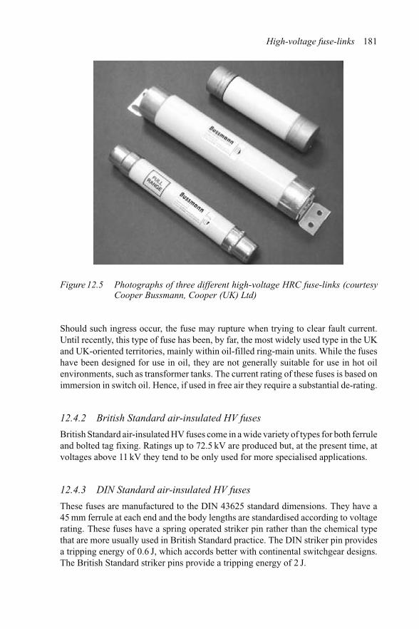
High-voltage fuse-links 181
Figure 12.5 Photographs of three different high-voltage HRC fuse-links (courtesyCooper Bussmann, Cooper (UK) Ltd)
Should such ingress occur, the fuse may rupture when trying to clear fault current.Until recently, this type of fuse has been, by far, the most widely used type in the UKand UK-oriented territories, mainly within oil-filled ring-main units. While the fuseshave been designed for use in oil, they are not generally suitable for use in hot oilenvironments, such as transformer tanks. The current rating of these fuses is based onimmersion in switch oil. Hence, if used in free air they require a substantial de-rating.
12.4.2 British Standard air-insulated HV fuses
British Standard air-insulated HV fuses come in a wide variety of types for both ferruleand bolted tag fixing. Ratings up to 72.5 kV are produced but, at the present time, atvoltages above 11 kV they tend to be only used for more specialised applications.
12.4.3 DIN Standard air-insulated HV fuses
These fuses are manufactured to the DIN 43625 standard dimensions. They have a45 mm ferrule at each end and the body lengths are standardised according to voltagerating. These fuses have a spring operated striker pin rather than the chemical typethat are more usually used in British Standard practice. The DIN striker pin providesa tripping energy of 0.6 J, which accords better with continental switchgear designs.The British Standard striker pins provide a tripping energy of 2 J.

182 Distribution switchgear
12.4.4 Motor circuit fuses
These fuses are specifically designed for the back-up protection of motors and theirassociated control equipment. The elements of a motor circuit fuse usually have stressrelief bends along their length to enable them to withstand the alternate expansion andcontraction they experience during the start up and running of direct-on-line motors.They are manufactured to the dimensions of the British Standard, DIN and NorthAmerican practice. It is normal to have these fuses mounted within the motor controlcubicle on the line side of the switchgear.
12.4.5 Instrument voltage transformer fuses
Instrument voltage transformer fuses are simple small diameter HRC fuse-links oflow current rating, typically 3 A. These fuses are connected in series with instrumentvoltage transformers and are intended to provide isolation for the system in the eventof a fault within the transformer. In practice, they have tended to introduce moreproblems than they solve, due to electrical discharge in the air space between thefuse and its housing in the cramped space that is normally available. They are notcommonly fitted to continental switchgear unless specifically requested.
In addition, as the maximum normal current that can be carried by an instrumentvoltage transformer is of the order of 200 mA, and that under ferroresonance condi-tions is a current of about 400 mA, a 3 A fuse will not provide any protection againstinternal burnout.
12.5 Full range HV fuses
As distinct from the back-up or partial range fuses described earlier, these fusesembody more recent technology which extends the minimum safe breaking capacitydown to the lowest value that can melt the fuse elements. Such fuses can, therefore,be used as sole protection in simple, low-cost housings, without the need for a strikerpin tripping mechanism to handle low fault current levels.
A common and effective method of ensuring full range performance is to includea special ‘miniaturised’ version of an expulsion fuse in the fuse body assembly withthe main current limiting elements (see Figure 12.6).
Within the full range fuse, the expulsion element handles low level fault currentsup to five to ten times the normal current rating, and the main elements take over toclear higher fault currents as in a conventional back-up fuse.
12.6 Fuse standards
IEC 60282-1, which equates to BS 2692-1, is the general standard for all high-voltage current limiting fuses. It is a large and comprehensive document and coversdefinitions, performance, test parameters and gives a fuse application guide.
IEC 60787 is a useful guide to the selection of high-voltage HRC fuses-links fortransformer protection applications. The standard sets out the various factors that need

High-voltage fuse-links 183
Silver elementsStriker coil
Ceramic former
Outer cap
Expulsion tubes Body Quartz filler
‘M’ effectSilicone rubber
Striker assembly
Figure 12.6 Cross-section through a typical full range high-voltage fuse-link(courtesy Cooper Bussmann, Cooper (UK) Ltd)
100
10
ab
ef
d
gc
Current
Tim
e (s
)
1
0.1
a: Transformer 100% loadb: 150% overloadc: Inrush currentd: High-voltage fusee: LV fuse characteristic transferred to the HV sidef: Upstream circuit breakerg: Maximum fault level on LV
Figure 12.7 Discrimination of circuit breaker, HV fuses and LV fuses
to be considered when choosing an HV fuse-link for a given application involving anupstream circuit breaker and transformer low voltage fuses (see Figure 12.7). Note:The transformer inrush current is taken as being equal to 12 times the full load currentfor 0.1 s.
IEC 60644 relates to HRC fuses for the protection of HV motor circuits. Thestandard details the special withstand tests with which motor protection fuses need tocomply and gives advice on the selection of such fuses for given applications. A fusedmotor control unit for direct-on-line motor starting is shown in Figure 12.8.

184 Distribution switchgear
Outgoingcable box
Currenttransformers
Circuit earthingswitch
compartment
Spouts
Busbarcompartment
Busbars
Isolating contacts Withdrawable truck(shown in isolated position)
Control VT
Main fuses
Vacuumcontactor
Isolatinghandle
Secondary plugand socket
LVcompartment
Busbar shutter
Figure 12.8 Cross-section through a type HMC1172 direct-on-line starter(courtesy of ALSTOM T&D Ltd)
IEC 605449 is the standard for high-voltage fuses that are to be used for theprotection of capacitors.
IEC60282-2 is the general standard for non-current limiting high-voltage fuses.This standard also covers outdoor types of expulsion fuses, which are widely used.
12.7 Distribution applications
A large number of high-voltage HRC fuses are used for distribution system protec-tion within secondary substations. They are to be found in a great variety of fusedswitchgear types, an example of which is shown in Figure 12.9.
IEC 60470 covers the various tests and test exemptions which apply to the use ofparticular fuse types and ratings within any given fuse-switch unit. The main areasof concern are:
(1) The I 2t and cut-off current values of a given fuse must not be greater than thosewhich the fuse-switch has been proven by test to be capable of withstanding.

High-voltage fuse-links 185
Figure 12.9 A ring-main unit, type T4GF3, fitted with high-voltage HRC fuses(courtesy of ALSTOM T&D Ltd)
(2) The transfer current, which is the maximum current that the switch has toclear unaided by the fuse during striker tripped operation, must be within thecapability of the switch to clear without incurring damage.
(3) The thermal performance of the fuse within the environment of a given fuse-switch must be acceptable. Appendix F of IEC60282-1 gives the methods to beused in order to determine the de-rating that will be required to avoid excessivetemperature rise and element deterioration in service.
12.8 Future trends
The 1980s saw the introduction of the first SF6 ring-main units. Most manufacturersdecided that, as it was not practicable to house high-voltage fuses within the gasenclosure because of fuse replacement problems, they would dispense with the fusesand produce units having a circuit breaker in the T-off section to control and protectthe transformer. Other manufacturers decided to retain the high-voltage fuses, buthouse them in specially sealed enclosures to protect them from the environment. Thissituation still remains today and the use of T-off circuit breakers in ring-main unitshas reduced the demand for high-voltage fuses.
Some electricity distributers have introduced simple three-phase box housingsusing full range fuses without an associated striker pin operated switch. The effect oflosing a faulty phase due to fuse operation, leaving the other two phases energised,may prove to be expensive if equipment burn out due to single phasing is the result.Time and experience will prove whether this solution has long term viability.


Chapter 13
Switchgear type tests
It is not the purpose, or possible, within the scope of this book to provide a detailedstep-by-step guide on the procedures to be followed when conducting developmentand type testing of switchgear. Indeed, such a guide would run into several volumesand, due to detailed changes in specifications that take place from time to time, itwould quickly become obsolete. It would also have to cover all types of switchgearincluding circuit breakers, switches, fuse switches, fuses, earth switches and discon-nectors. However, the intention here is to give an overview of the important stages intesting that have to be completed in order to provide switchgear that is safe and ableto operate correctly in the circuits and ambient conditions for which it is intended.By way of example, particular reference will be made to circuit breakers. The oppor-tunity will be taken to highlight certain aspects of each type test in order to show therelative importance and the way in which solutions to encountered problems can, andusually will, have an influence on the performance of other type tests.
13.1 Reports and certificates
Testing laboratories issue two forms of test document which detail the tests that areconducted, giving the test parameters and the equipment performance. The documentshave specific names to avoid confusion. The first is a ‘Report of Performance’ andthe second is a ‘Certificate of Rating’. There is a significant difference between thesedocuments that must be understood, as superficially they are similar in appearance. Itis clearly important that those who are not familiar with them understand the differencewhen evaluating the suitability of switchgear for a specific application. The similarityin appearance of both types of document can be seen in Figure 13.1.
Figure 13.1 shows the front sheet of a Report of Performance on the left-hand sideand a Certificate of Rating on the right. Both documents have a hard-back binding andhave the testing station seal, but the title wording identifies each type of document.The appearance of each is substantially similar, demonstrating how the inexperiencedexaminer could be confused.

188 Distribution switchgear
Figure 13.1 Report of Performance and Certificate of Rating documents(photograph courtesy of the KEMA Laboratories)
The conditions under which the test authority will issue these documents isexplained in the following:
The testing authority will issue a ‘Report of Performance’ when
(1) there is no specific national or international standard covering the equipmenttested;
(2) the values used for the tests were not in accordance with a specific standard;(3) the complete tests in the specification were not carried out to the letter;(4) the equipment fails some aspect of the tests in the standard.
The testing authority makes it clear that when copying a ‘Report of Performance’, thewhole of the document must be copied, not just the front sheets. It should be notedthat the report might not include any or full identification of the equipment tested,and the testing authority will not necessarily verify any identification that is included.
A ‘Certificate of Rating’ is issued by the testing authority when the equipmenttested meets all of the requirements of the standard, and the associated STL guide,in every detail. It has been known for a ‘Certificate of Rating’ to be withheld and a‘Report of Performance’ to be issued in its place because of an anomaly in the post-test no-load travel records. Only the front sheets of a certificate need be copied forperformance evidence, as the testing authority puts its reputation behind the validity ofthe claimed performance. The complete ‘Certificate of Rating’ must contain sufficientinformation to accurately identify the equipment tested, which the testing authorityverifies at the time of test.
A ‘Report of Performance’ should not, however, be dismissed. The question thatthe reviewer needs to ask is ‘why was a certificate not issued?’. If a satisfactoryexplanation is given, the reviewer will then need to examine, in detail, every aspectof the report to ensure that all aspects, such as transient voltage recovery, current, peakcurrent, d.c. component and time intervals in a sequence, meet the specified values.

Switchgear type tests 189
13.2 National and International Standards
Most countries have produced their own National Standards for switchgear. For exam-ple, the British Standards Institute has a standard covering a.c. circuit breakers. Inaddition, some 22 countries have taken an active part in producing an InternationalStandard covering the same equipment and voltage range, under the auspices of theInternational Electrotechnical Commission, known as the IEC, which is based inGeneva. In addition, end-user standards such as the Electricity Association Techni-cal Standard EATS41-36, ‘Distribution switchgear for service up to 36 kV (cable &overhead conductor connected), issue 1, 2000’, which defines the specific require-ments of the UK, add to the International Electrotechnical Commission standards,those requirements which are seen as being necessary in the UK. The complete listof reference standards relating to switchgear is formidable but the most important arelisted in Chapter 18.
Other switching equipment, such as contactors, earth switches, disconnectors andfuse-switch combinations, have their own specific standards. These also share somerelated standards with circuit breakers. These shared requirements are published inan IEC ‘Common clauses’ document.
It should be noted that all standards, including those produced by the IEC andElectricity Association are all under consideration for modification at any time. It is,therefore, very important to ensure that the latest edition is used.
13.3 Development tests
Development tests are carried out by manufacturers to allow the performance ofdesign concepts and completed prototypes to be explored. These tests fall into fourcategories:
(1) test rig work;(2) exploration of the limits of performance;(3) proving a new product before certification, or proving changes to an established
product before re-certification;(4) certification tests.
Taking each in turn:
(1) At the outset of the development of a new product, the design team will identifythose areas of the design which may contain a measure of technical speculation.Test rigs will then be designed and built so that tests can be carried out in orderto be certain that working solutions have been found and that these solutions canbe built into the prototype design. These test rigs can be produced to look at anyarea of the design, thermal, mechanical or electrical, and will usually includemeasuring transducers which, of course, do not form part of the eventual productthat will be type tested.
(2) While some test rig and development testing will be carried out at in-house testfacilities, development tests to explore the limits of performance may need to
190 Distribution switchgear
be conducted at independent testing stations such as KEMA in the Netherlands,CESI in Italy and BSTS in the UK. As test rig and development tests arecontrolled by the manufacturer, and would not necessarily comply with therequirements of a specific standard, these testing stations would issue Reportsof Performance detailing the test results obtained whether or not the results weresuccessful.
(3) During the course of test rig and development tests, changes may be made tothe design in order to optimise the performance. When individual aspects ofperformance have been proved in isolation, it is very important to prove thecomplete design, before certification. This is to check for any unforeseen inter-action between the previously unlinked components. Similarly, the influenceof design changes to an established product should be established by test ifproblems in service are to be avoided.
(4) Certification tests will be carried out by an approved independent testingauthority. The term ‘independent’ means that, while it may be owned by amanufacturer, the testing station will have complete technical independenceand the test results will remain confidential between the testing station and theclient, usually a manufacturer, paying for the tests. The testing station will con-trol all aspects of the tests to be conducted without any interference from theclient, although it is normal for them to attend and witness the tests. These test-ing stations will issue a Certificate of Rating to a nominated standard, however,for this to be issued all aspects of the tests must be faultless, and to the letter ofthe standard.
Complete type tests on a circuit breaker will include the following tests:
(1) Mechanical operation.(2) Temperature rise.(3) High-voltage
power frequency, dry, on the primary circuit;power frequency, wet, on exposed insulated designs;power frequency on secondary wiring;basic impulse level (BIL);partial discharge.
(4) Short-circuitterminal faults;low-inductive switching;capacitor switching;back-to-back capacitor switching;internal arc faults.
(5) Environmental teststemperature cycling;icing tests on outdoor switchgear.
(6) EMCelectromagnetic compatibility.
We will look at them in more detail.

Switchgear type tests 191
13.3.1 Mechanical operations
For conventional circuit breakers, this consists of a total of 2000 operating cyclescarried out under defined conditions. For autoreclosers, this figure is 4000 operatingcycles. The electrical integrity of the test circuit breaker is established at the beginningand end of the tests, and moving contact travel records are taken periodically duringthe test. Some of the operations are arranged to be of the make–break type; that is,the initiation of the opening trip operation is via the main contacts, which, for thispurpose, are connected in the trip circuit.
At the end of the tests, the criteria to be met are:
(a) The operating travel characteristics at the end of the tests should be substantiallythe same as those recorded at the beginning.
(b) The electrical integrity of the test circuit breaker should be confirmed.(c) A detailed examination of all parts should confirm that no undue distortion or
wear has taken place.
The normal sequence of operations used for the test is given in Figure 13.2.
13.3.2 Temperature rise
It is a surprise to those who do not know, but nonetheless true, that the normal currentrating of a circuit breaker is determined by the measurement of the temperature riseof critical components when passing the rated normal current. In this test, measure-ment is carried out by the attachment of thermocouples to the critical components andrecording the results. For tests on a circuit breaker, if it is of the switchboard type,the test circuit breaker will have its external side sheets insulated with 25 mm thick
Operatingsequence
Controlvoltage Circuit breakers for
autoreclose dutyCircuit breakers notfor autoreclose duty
Number of operating sequences
Minimum
Rated
Maximum
Rated
Rated
500
500
500
500
500
500
500
–500
–
C – ta – O – ta
C – CO – ta – CO
CO – ta
Figure 13.2 Table of rated sequences for the mechanical operations test

192 Distribution switchgear
Thermal insulation
Testobject
Input fromtransformer
1 m
1 m
Star point
T3T4
T2 T1
Figure 13.3 Temperature rise test arrangement
Type of connectionMaximumtemperature rise (°C)
75
65
65
55
Plain copper, bolted
Plain copper contacts
Silver plated contacts
Silver plated, bolted
Figure 13.4 Table of maximum allowable temperature rise
polystyrene foam sheets. This is to ensure that no heat is lost to adjacent switchboardpanels. The current used for the test is usually supplied at low voltage by a trans-former and its value is also monitored. The connections to the test circuit breakerare by copper bars at least 1 m long, as are the connections to the star-bar. Thetemperature difference between the direct connection to the test circuit breaker andthat measured 1 m away must be maintained within 5◦ to ensure that the test circuitbreaker is not exporting heat. The ambient air temperature is also monitored (seeFigure 13.3).
The maximum temperature rise recorded must be equal to, or less than, thatallowed in the specification. These specified values depend on the type of connection,the materials involved and whether or not silver plating has been used. Refer to therelevant standard for a comprehensive list of allowable temperature rises, however,some examples of the specified maximum allowable temperature rises are given inFigure 13.4.
If the maximum temperature rise is in excess of that allowed, the switchgeardesigner will have to decide on the measures to be taken, and has two choices. He willeither have to arrange to create less heat, although even a small excess in temperaturerise will be very difficult to reduce by this method, or he will have to transfer the

Switchgear type tests 193
excess heat to either the atmosphere, with increased ventilation, or to other areaswithin the switchgear where the temperature is lower. If this latter method is used,care must be taken to safeguard compartment integrity in the event of an internal arc.Sometimes a matt black surface finish will be used to increase thermal emissivity ofcritical components. This will increase thermal emissivity by about only 2 per centbut this may be sufficient in some cases.
The temperature rise at each thermocouple is usually measured and recorded everyhour on a data logger and the test is completed when a steady state is reached. Thisis defined as being when the measured temperature does not increase by more than1◦C in 1 h.
A switchboard type circuit breaker, having its sides clad with polystyrene foamsheet to prevent heat loss to adjacent panels, together with a data logger for con-tinuous temperature monitoring and recording can also be seen as shown on test inFigure 13.5.
In the early stage of a development, there may be several arrangements thatrequire testing and these tests may consume a great deal of time. When the testcurrent is switched on, the temperature of components will start to increase fromthe starting ambient temperature. The temperature rise will follow a heating curve,which is mathematical in its nature. The maximum, or steady state, temperatureof this heating curve can be determined early in a test by taking three temperaturereadings at equal time intervals and using these to calculate the maximum value thatwould be attained. A temperature rise curve with marked time intervals is shown inFigure 13.6.
Figure 13.5 A panel type circuit breaker on temperature rise test (courtesy ofALSTOM T&D Ltd)

194 Distribution switchgear
Final temperature
Air temp
C deg
t4t3t2
t1
Time
Figure 13.6 Temperature rise with equal time interval measurements
A heating or cooling curve is defined by the equation
Tr = Tmax(1 − ε−t/τ )
where Tr is the temperature rise, Tmax, the maximum temperature rise, ε, the Napierianlog base, τ , the time constant and t , the time from start.
The heating curve in Figure 13.6 is mathematical, and the successive elements oftime form a geometrical progression, where each term is equal to the preceding termmultiplied by the common ratio. The total to infinity of such a series is
S = a
1 − r
where a is the first term and r , a common ratio.Referring to Figure 13.6, if a circuit breaker is being evenly heated by the passage
of electric current then it will gain a temperature of t1 in the first interval and a furthertemperature t2 in the second interval, which is equal to the first, then:
a = t1
and
r = t2
t1
Thus
S = t1
1 − (t2/t1)
= (t1)2
t1 − t2
(temperatures t1 and t2 are in ◦C).More generally, if three thermocouple readings are taken at equal intervals of
time, say t1, t2 and t3, at any stage of a temperature rise test, the values obtained can

Switchgear type tests 195
be used to predict the maximum temperature rise that will be achieved.
Tr = t2 − t1
1 − (t3 − t2)/(t2 − t1)
Example 13.1During a temperature rise test on a prototype circuit breaker, three thermocouplereadings were taken at 20 min intervals. The readings were 21.5, 27.1 and 32◦C.What is the predicted final temperature rise above the starting temperature?
Given
Tr = t2 − t1
1 − (t3 − t2)/(t2 − t1)
And substituting the thermocouple readings
Tr = 27.1 − 21.5
1 − (32 − 27.1)/(26.2 − 21)= 5.6
1 − 0.875
= 5.6
0.125
Therefore, the temperature rise
= 44.8◦C.
There is a relationship between the steady state temperature rises experienced by acircuit breaker for two different constant currents over the normal working ambienttemperature range. This relationship is
T1
T2= [I1]δ
[I2]δ
The suffixes 1 or 2 denote the two test conditions.This relationship is very useful for calculating the likely normal current that can
be safely carried when a circuit breaker is to be installed in an ambient temperature inexcess of the standard maximum of 35◦C. As previously explained, the normal currentrating of a circuit breaker is determined by the temperature rise above an ambienttemperature when carrying a current equal to the rated value. This means that the actualmaximum temperature allowed is the temperature rise added to the maximum allowedambient temperature. If the circuit breaker is to be installed in a site where the ambienttemperature is in excess of the maximum value, the allowed temperature rise must bereduced by 1◦C for every degree by which the ambient exceeds the specified value.The following is a worked example showing how the new rating can be determined.

196 Distribution switchgear
Example 13.2An 11 kV circuit breaker was found on test to have a maximum temperature rise of65◦C when carrying a continuous current of 630 A. The same circuit breaker hada maximum temperature rise of 60.69◦C when carrying a lower continuous currentof 600 A. What would be the likely maximum permissible continuous current ratingif the circuit breaker was to be installed on a site where the steady state ambienttemperature would be 54◦C?
Given that
T1
T2= [I1]δ
[I2]δSubstituting the known test values into the expressions:
65
60.69= (630)δ
(600)δ
Therefore
1.071 = 1.05δ
Taking logs to the base 10 of both sides of the expression
0.0298 = δ × 0.0212
Therefore
δ = 0.0298
0.0212= 1.4
As the proposed ambient temperature is to be 54◦C, the allowable temperature risewill be reduced by a value equal to 54◦C minus the standard maximum ambienttemperature of 35◦C, giving a 19◦C reduction, making the allowed temperature rise65◦C minus 19◦C, equal to 46◦C.
Substituting the known values into the given expression
65
46= (630)1.4
(I2)1.4
Therefore
1.4√1.4 = 630
I2
making
I2 = 500 A.
Therefore, the 630 A rated circuit breaker would have to be de-rated to 500 A if it hadto operate in a steady state ambient temperature of 54◦C.

Switchgear type tests 197
Before leaving the subject of temperature rise tests, there are a number of importantissues that are worth noting.
• It is usually more difficult and more expensive to produce less heat by increasingthe cross-sectional areas than is initially thought. Even an excess temperature ofonly, say, 2◦C or 3◦C would be very difficult to eliminate.
• Within air-insulated switchgear, conduction and ventilation to cause heat to flowinto cooler areas may offer a better solution.
• Important solid insulation in air-insulated switchgear should always be verticallyaligned rather than horizontal to increase air flow and reduce the possibility ofcontamination which could lead to insulation failure.
• It is sometimes useful to use brass castings as part of the conducting circuit. Careshould always be taken, both at the prototype and production stage, to ensurethat the brass does not include any phosphorous, as even a minute quantity willdrastically reduce its conductivity and cause an increased temperature rise.
13.3.3 High-voltage tests
Three types of test are used to determine the insulation integrity of switchgear. Theseare the power frequency, basic impulse and partial electrical discharge tests.
13.3.3.1 Power frequency tests
Power frequency tests, sometimes known as the high pot or flash tests, are carriedout using a test voltage of about 2.5 times the rated voltage at the rated frequency.These tests are designed to stress the insulation of the test switchgear, both inter-phase, interpole and to earth. This test also is carried out on production units asa routine test. A wet power frequency test is carried out on switchgear intendedfor outdoor use with exposed insulation. For this test, a finely divided spray ofwater with a specified salinity is directed at the insulation while the test voltageis applied.
A 2 kV power frequency test of 1 min duration is carried out on the secondarywiring of switchgear. This test is also carried out on production units as a routine test.
13.3.3.2 Basic impulse tests
The basic impulse level (BIL) withstand test is designed to stress the insulation ofswitchgear by the repeated application of a very steep fronted voltage wave and is avery searching test of the unit’s insulation integrity. The shape of the impulse voltagewave is specified to be 1.2 μs/50 μs, which means that it has to reach its specifiedBIL peak voltage value in 1.2 μs and have a wave tail which falls to half of the BILpeak value in 50 μs (see Figure 13.7).
The impulse voltage wave is provided by an impulse generator which is essentiallya bank of capacitors which are charged up connected in parallel, and discharged ina series connection by the triggering of sphere gaps. A photograph of an impulsegenerator is shown in Figure 13.8.
The basic impulse test consists of 15 consecutive impulses, of both polarities,applied to each pole in turn with the circuit breaker open and all other poles earthed,

198 Distribution switchgear
Peak(kV)
1.2μs 50μs Time (μs)
Half peak
Figure 13.7 Standard basic impulse level (BIL) waveform
Figure 13.8 An impulse generator (photograph courtesy of the KEMALaboratories)
and then to each phase in turn with the other phases earthed, as shown in Figures 13.9and 13.10. The rules do not allow more than two disruptive discharges in any 15.
In order to ensure that all insulation, interphase, phase to earth and across contactgaps are proven, the eleven arrangements shown in Figure 13.10 must be tested.

Switchgear type tests 199
Busbarsab
c
Cablebox
AB
C
F
Figure 13.9 Terminal identification for high-voltage tests
Test sequence
1
2
3
4
5
6
7
8
9
10
11
Switching device
Open
Open
Open
Open
Open
Open
Closed
Closed
Closed
Not inserted
Not inserted
Voltage applied to
A
B
C
a
b
c
Aa
Bb
Cc
ABC
abc
Earth connected to
BC abc F
AC abc F
AB abc F
bc ABC F
ac ABC F
ab ABC F
Bb Cc F
Aa Cc F
Ab Bb F
F
F
Figure 13.10 Test arrangements
13.3.3.3 Partial discharge tests
Partial electrical discharge taking place within switchgear can, by the formation ofnitric acid and nitric oxide, eventually lead to catastrophic failure. Electrical dischargecan take place across stressed air gaps between insulation and materials at earthpotential. Most manufacturers design their equipment to ensure that the levels ofvoltage at which discharge inception and extinction take place are well above themaximum value applied by the system voltage.
Discharge inception occurs on a rising voltage, and discharge extinction will takeplace as the voltage returns towards zero. However, inception always occurs at ahigher voltage than extinction. In order to guard against electrical discharge continu-ing when the voltage returns to normal, it is usual to arrange for discharge extinctionto be at least 10 per cent above that applied by the maximum system voltage. Withthese values, a modest system voltage excursion will not induce electrical discharge,and larger voltage excursions will automatically be extinguished once the systemreturns to normal. It will be seen that on an unearthed system, running with one phasedown to earth, the inception and extinction voltages will need to be higher than thoseinstalled within an effectively earthed system, and the switchgear must meet thesehigher levels if discharge is to be avoided.

200 Distribution switchgear
(a) Discharge free (b) With discharge
Figure 13.11 (a) and (b) An ERA-type discharge detector (courtesy of ALSTOMT&D Ltd)
Current specifications require tests to be carried out on components, but not oncomplete equipment. However, draft changes to National and International specifi-cations are currently being discussed and it is likely that these tests will be includedin the near future.
Discharge inception and extinction levels are measured during type tests byinstalling the switchgear in a Faraday cage and using a discharge detector (seeFigure 13.11).
If no discharge is detected, the elliptical display on the measuring equipment willbe undisturbed, as shown in Figure 13.11(a). When discharge is present, the ellipticaldisplay will show tearing and discontinuity as shown in Figure 13.11(b).
13.3.4 Short-circuit tests
Short-circuit fault testing is the most expensive form of type testing that has to becarried out. This is because the testing station is equivalent to an electrical powergenerating station, but with generators and test transformers designed to produce veryhigh levels of short-circuit current necessary to reproduce fault conditions. Sophist-icated measuring and adjustment of circuit power factor and current level is necessary,as well as point-on-wave fault initiation. Testing stations are therefore very expensiveto construct and run. Some manufacturers have there own in-house short-circuit testfacility, such as BSTS in the UK which are run as independent units having their owntest observers, and other testing stations are independent of manufacturers, such asthe KEMA Laboratories in the Netherlands and the CESI laboratories in Italy. Thesize and complexity of one of these testing stations can be seen in Figure 13.12.
13.3.4.1 Terminal short-circuit faults
National and International standards specify that three operations, in the circuitbreaker rated sequence, shall be carried out at 10, 30, 60 and 100 per cent of thesymmetrical fault current level using a specified rate of rise of recovery voltage ateach level. Also at each level, the final two break operations should be preceded by afault make operation. Indeed, the fault make operation is mandatory at the 100 per cent

Switchgear type tests 201
Figure 13.12 Part of the KEMA test facilities in the Netherlands (photographcourtesy of the KEMA Laboratories)
symmetrical fault level. Figure 13.13 shows an oscillogram of test duty 4, 100 per centfault rating test carried out as an O–CO sequence.
At first sight, the oscillogram shown in Figure 13.13 appears to be very com-plicated, but once the individual traces on the record are identified, the oscillogrambecomes much easier to understand. It can be seen that the record gives a completepicture of all that happens during a Test Duty 4, O–CO sequence, at the 100 per centrated fault level. The top two traces show the current in the trip and closing coil.Moving down the oscillogram, the voltages and current in each phase, R, Y and B,are shown. Superimposed upon these traces is the contact travel record. The trace atthe very bottom of the record is designed to detect any transient earth fault currentflowing to the circuit breaker enclosure.
The sequence of events, starting with the test circuit breaker contacts closed andno current flowing, can now be examined by starting at the left-hand edge of theoscillogram and moving to the right, in the direction of elapsed time.
• The first change we see is the appearance of fault current in each phase.• Next, at the top of the record, current can be seen to flow through the trip coil. This
current shows the characteristic dip that occurs when the coil armature moves,changing the coil impedance.
• Shortly after this, the moving contact record shows that the contacts have startedto move towards the OPEN position.
• Part way through this contact movement the fault current can be seen to beextinguished and a recovery voltage appears across the contact gap in each phase.
• The contacts remain in the OPEN position, in this case for 300 ms, as the circuitbreaker being tested is intended for use in autoreclose applications.

202 Distribution switchgear
Trip coil current
Contact travel OPEN
CLOSED
Earth fault current
Time
kV
kV
kV
kA
kA
kA
B
Y
R
Closing coil current
Figure 13.13 Oscillogram of Test Duty 4, 100% rated fault level (courtesy of theKEMA Laboratories, Netherlands)
• Towards the end of the ‘dead-time’, it will be seen that current starts to flow inthe closing coil and the moving contacts move to the CLOSED position, causingfault current to flow.
• The testing station will energise the trip coil to initiate the trip operation at a timewhen the transient reactance of the fault current has decayed to not more than20 per cent, which is the maximum specified value for this test duty.
• Once again the circuit breaker contacts will move towards the OPEN position,interrupting the fault current, and a recovery voltage then appears across thecontact gap of each phase.
13.3.4.2 Asymmetrical breaking capacity, Test Duty 5
In addition to the symmetrical breaking capacity tests, which are Test Duties 1–4, testshave to be carried out with a level of current asymmetry having a d.c. component.
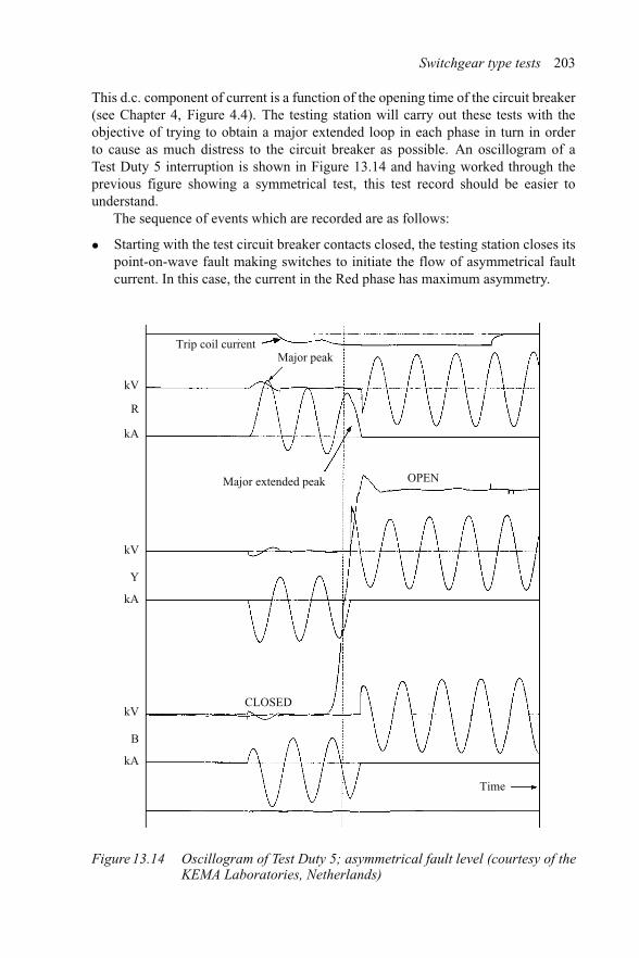
Switchgear type tests 203
This d.c. component of current is a function of the opening time of the circuit breaker(see Chapter 4, Figure 4.4). The testing station will carry out these tests with theobjective of trying to obtain a major extended loop in each phase in turn in orderto cause as much distress to the circuit breaker as possible. An oscillogram of aTest Duty 5 interruption is shown in Figure 13.14 and having worked through theprevious figure showing a symmetrical test, this test record should be easier tounderstand.
The sequence of events which are recorded are as follows:
• Starting with the test circuit breaker contacts closed, the testing station closes itspoint-on-wave fault making switches to initiate the flow of asymmetrical faultcurrent. In this case, the current in the Red phase has maximum asymmetry.
kV
kV
kA
R
Y
kVCLOSED
Time
OPENMajor extended peak
Major peakTrip coil current
kA
B
kA
Figure 13.14 Oscillogram of Test Duty 5; asymmetrical fault level (courtesy of theKEMA Laboratories, Netherlands)

204 Distribution switchgear
• The testing station then initiates current in the test circuit breaker trip coil to openthe circuit breaker so that the rated degree of asymmetry will be present at thetime of contact separation.
• The moving contact travel trace shows the start of movement towards the OPENposition.
• The contacts separate just before current zero in the Yellow phase, allowing thatphase to clear with only a few milliseconds of arcing, causing a phase shift ofcurrent in the other two phases which make their values equal and opposite.Recovery voltage appears across the Yellow phase.
• The current in the Red phase, which has a high level of asymmetry, can be seento be extended by the phase shift.
• The currents in both the Red and Blue phases then clear and a recovery voltageappears.
The testing station would then attempt to move the point of contact separation inorder to obtain a major extended loop in each phase in turn, but the STL guide willonly permit them to carry out a maximum of six break operations at the Test Duty 5level. During development tests, it is good practice to arrange for clipped amplifiedvoltage records across each phase to look for possible problems with the test circuitbreaker contacts when experiencing peak fault currents.
13.3.4.3 Short time current test
A short time current test is carried out to confirm that the circuit breaker being testedis able to withstand safely its rated peak and rms short-circuit currents. The contactloading of the circuit breaker must be high enough to prevent burning or welding atthe contact interface, and the thermal capacity of the current carrying componentsmust be such that no problems will materialise on the short time current test. Onceagain, it is good practice to employ amplified arc voltage traces when conductingdevelopment tests, as these will show up potential problems as the test generatorexcitation is progressively increased. An oscillogram of a short time current test isshown in Figure 13.15.
The electromagnetic forces that are produced by Test Duty 5 and the first peak ofthe short time current test may cause damage to brittle insulation on conductors. Itis therefore, good practice to thoroughly examine this insulation at stages during thedevelopment tests.
13.3.4.4 Other switching duties
Other switching duties may be proved by type tests if the test circuit breaker is to beassigned specific ratings. These include:
• small inductive current switching;• single capacitor bank switching;• back-to-back capacitor switching.
All of the above are discussed in Chapter 6.

Switchgear type tests 205
V
kA
kA
kA
V
VB
Earth fault currentTime
Y
R
Figure 13.15 Oscillogram of a short time current test (courtesy of the KEMALaboratories, Netherlands)
13.3.4.5 Internal fault tests
The internal fault tests are designed to prove that personnel will not be injured in theevent of an arcing fault within switchgear. These tests are the most expensive that amanufacturer has to face because prototypes are typically five to ten times the costof production units, and these tests effectively scrap the units being tested. At theoutset of the tests, there is a degree of technical speculation and, under what is tosome extent a trial-and-error process, several repeat tests may be necessary. This isbecause the effect of the rapid pressure rise within flat-sided cubicle constructionsand arc burn-through time cannot be accurately predicted.
The Electricity Association standard EATS41-36 ‘Distribution switchgear for ser-vice up to 36 kV’ specifies that internal fault tests are mandatory. The tests are alsodetailed in IEC60298, CENELEC prEN 50179, HN64-S40, S41 and S42 in Franceand DIN VDE 0670 in Germany.
EATS41-36 specifies that the magnitude of the current to be used for the tests isto be equal to the rated symmetrical breaking capacity of the switchgear being tested,and the duration of the current is specified as one second. In all other respects, thetests are to be in line with the requirements of IEC60298.
For these tests, fuse wire is used to initiate an internal fault separately within thebusbar, circuit breaker and cable box spaces.
The positions where personnel are likely to be in the course of their normal dutiesare specified in the standards, and are simulated by cotton squares mounted on steelframes. These cotton squares, known as ‘indicators’, must not be ignited or piercedby ejected debris. Figure 13.16 shows a circuit breaker with a framework erected andfitted with the cotton indicators in their frames.
The tests can be quite dramatic to witness as considerable noise, smoke and flameis produced. Quite often the smoke will prevent observation of the test unit for a time.An impression of this test can be seen in Figure 13.17.

206 Distribution switchgear
Figure 13.16 A circuit breaker with frames and indicators (courtesy of the KEMALaboratories, Netherlands)
Figure 13.17 A circuit breaker on internal fault test (courtesy of the KEMALaboratories, Netherlands)
The inclusion of ‘blast-flaps’ in the switchgear enclosure is the usual solution thatis applied to dissipate the pressure build-up which will occur if an internal fault isto be allowed to burn for the full rated duration. The blast flap is usually a hingedcover which opens within about 10 ms of the start of the fault. The vent area providedby the blast-flap can be quite large and for smaller fault levels may represent thepoint in time of the generated peak pressure. However, at higher fault levels, theinternal pressure may continue to increase after the blast-flap has opened, but at alower rate. Development engineers have found that with some equipment, especiallywhen tested for a fault duration of greater than 1 s, certain areas of the design will

Switchgear type tests 207
Table 13.1 Test criteria for various levels of protection
Criteria no. Assessment of test
1 Doors and covers do not open2 Hazardous parts do not fly off3 No burn-through of external surfaces4 Vertical indicators do not ignite5 Horizontal indicators do not ignite6 All earthing connections still intactProposed 7 Adjacent compartments can be returned to service after cleaning
required a second metal skin to prevent arc burn-through, regardless of the currentmagnitude. Some designs even have a built-in feature that is intended to act as anarc root point in order to control the arc’s position. The development tests also quiteoften show that some reinforcement of the construction is necessary, particularly inthe area of doors, removable covers and chambers having large flat sides. Table 13.1shows the test criteria for various levels of protection.
Internal fault test specifications fail to recognise that the protection provided islimited to blast and heat, which, while a big advance on no protection at all, does notprotect the operators from other phenomena. For example, hearing damage may becaused by the associated very loud sound, and no protection for personnel is providedagainst exposure to arced SF6 if this is vented within a substation.
Those who specify switchgear should note that the internal dimensions of substa-tions will influence the internal fault test results. For example, the blast from faultedequipment could be reflected back, perhaps towards an operator, so the height of thesubstation ceiling is important. The specifier should study the type test report andensure that the dimensions of the proposed location are equivalent to that used forthe tests. Consideration should also be given to the substation materials to ensurethat they can withstand hot gases and flames being issued from faulted equipment.Finally, there are ways of meeting the requirements for operator safety in the eventof an internal fault by not letting it continue for the full rated duration. These arenovel solutions which are not yet recognised by existing standards [19]. Some ofthese solutions are:
• Fitting a robust auxiliary switch to the blast flaps, so that the incoming feedercircuit breaker will be tripped in the event of the blast flap opening. Correctoperation of this system can be verified by a simple test at any convenient timein the life of the switchgear.
• The inclusion of a light detector in the zone to be protected which will initiate asignal to a relay where it will stored, even if the light detector is destroyed by thefault. A second signal would be sent simultaneously from a current transformerin the feeder circuit breaker, and when both signals are present, the relay willinitiate tripping of the incoming feeder circuit breaker.
208 Distribution switchgear
• The third method, used in France, is similar to the previous one, but instead ofusing a light detector, it measures the pressure rise within a faulted compartment.
• A fourth method, used in Switzerland, is similar to the previous two, but usessound instead of light or pressure to detect an internal fault. However, this methodcannot identify an individual faulted chamber.
• Finally, there is another novel method that is worthy of note. This was introducedby Driescher in Germany and uses deflection of the walls of an SF6 compartmentto trigger the closure of a three-phase earth switch on the incoming side to effec-tively short out the fault. It is obviously important that any protection which usesa separate switch to short out a fault must be capable of having its mechanicaloperation checked during the life of the equipment.
13.3.5 Environmental tests
The environment can influence the performance of switchgear in different ways, anda series of tests must be carried out to ensure that the switchgear is immune to adverseenvironmental influences and is able to perform correctly in all specified conditions.The aspects of performance that have to be checked are:
(a) gas tightness;(b) operating times and speeds;(c) water ingress; and(d) icing.
13.3.5.1 Gas tightness
Halogen gas leakage detectors are sensitive, calibrated measuring devices, and manu-facturers use them to measure their success in achieving their target of zero gasleakage. In order to verify a virtually zero gas leakage rate, measurements must bemade under high and low temperature conditions, as well as before, during and aftermechanical operations tests. The reason for this is that gas sealing materials willexpand and contract with changes in temperature at a faster rate than metals usedin parts, such as shaft and covers. In addition, certain types of seals will lose theirelasticity or even become brittle at low temperatures.
If there is going to be a gas leakage problem, it will occur in one of three condi-tions: the first condition is when the switchgear is being returned to normal ambienttemperature after being held at its minimum rated temperature for sufficient time forall parts to reach that minimum temperature. Due to loss of elasticity, shaft and coverseals may lose their flexibility and not be able to maintain a sealing pressure on theirassociated metal parts when they start to warm up and expand. The second conditionis at high temperatures, when the seals may have become semi-plastic and, therefore,lost their ability to remain effective.
Finally, dynamic seals may become ineffective due to wear or deformation causedby repeated mechanical operations.
For reference, various types of leak detection methods and the sensitivity of each,are given in a tabular format in IEC 60694 Annex E, which also gives an example ofsummation tests for interconnected compartments.

Switchgear type tests 209
13.3.5.2 Operating times and speeds
To be certain of correct co-ordination with protection schemes and with other equip-ment on the distribution system, it is essential that the opening, closing and contacttravel speeds are measured at both high and low temperature as well as periodicallyduring the mechanical operations tests. These times and speeds need to be essen-tially the same at both the start and the end of the mechanical operations tests, andany variation at high or low temperature should be noted in the type test report.
13.3.5.3 Water ingress
Water entering switchgear will, almost certainly, have disastrous consequences. Alloutdoor switchgear is, therefore, required to be subjected to water ingress tests. Thesetests are detailed in Annex C of IEC 60694, which specifies water spray nozzlepositions and rates of water flow.
The tests are deemed to be successful if:
(1) Apart from that on external insulation, no water is visible on the insulation ofthe main and auxiliary circuits.
(2) No water is visible on any internal electrical components or mechanism.(3) No significant accumulation of water shall be retained by the structure, as it
could cause corrosion.
Clearly, if water does enter and accumulate within the structure, the definition ofthe word ‘significant’ in clause 3 of Annex C would be of paramount importance.A prudent engineer would avoid any discussion by not allowing any water to entera unit.
13.3.5.4 Icing tests
Tests need to be carried out to confirm that ice accretion in and around external driveshafts and handles will not prevent correct operation. This can be a particular dangerwith open type, pole-top switchgear.
The international standard IEC 60129 specifies how the ice should be formed andthe tolerances on its thickness, which is measured on a test bar. Once the ice hasbeen formed, the switchgear being tested has to be held at a temperature of −7◦Cfor at least 4 h. This is to ensure that all parts, and the ice, have assumed a constanttemperature.
Having achieved a constant temperature, the unit must operate correctly on thefirst attempt to move to its final closed or opened position. The switchgear should nothave sustained any damage that could later interfere with its electrical or mechanicalperformance. Switchgear designers should prevent a possible operational problem byarranging for the first part of the operation to have an ice-breaking feature, such as aninternally expanding scissor type lever mechanism with a high mechanical advantage.
13.3.6 Electromagnetic compatibility tests
The interaction between switchgear and the circuit in which it is installed can, duringswitching, give rise to voltage spikes and high-frequency voltage oscillations which

210 Distribution switchgear
Figure 13.18 A subterranean EMC test facility
have the potential to interfere with other equipment. It is important that steps are takento prevent or minimise this electromagnetic interference. Generally, there are threeways in which possible interference can take place. These are via conduction, radiationand induction, and there are remedies that eliminate or minimise all three types.
Switchgear that uses electromechanical relays will clearly not be interfered withby external sources, but some newer forms of electronic auxiliary switches and alter-natives to conventional current and voltage transformers are susceptible and needprotection. Within current conventional switchgear, electronic control and protectionrelays are now widely used, and these could suffer maloperation if the electromag-netic field levels in their vicinity exceed the levels of protection that they have builtinto their construction. Short-circuit testing of switchgear fitted with protection andcontrol relays can prove the combination, or will very quickly show that there is aninterference problem.
National and International standards at present do not call for switchgear to com-ply with the EU Directive on Electromagnetic Compatibility (EMC), as they arecurrently considered to be part of a complex whole. However, operation and controlrelays do have specified levels of compatibility and they must be separately proven.The situation with regards to standards needs to be carefully watched as changes maybe introduced. Some customer standards specify levels of EMC, and most manufac-turers will have carried out tests to determine the characteristics of their switchgear.Tests are usually conducted within a dedicated test house, and an interesting one isshown in Figure 13.18.
The test facility shown in Figure 13.18 is housed within a disused salt minein Cheshire, which was found to be an ideal environment for the elimination ofextraneous electromagnetic interference.

Chapter 14
Product conformity, quality control and serviceproblem resolution
As it is neither practicable, nor economically feasible to type test every productioncircuit breaker or switch, instead, manufacturers are confined to carrying out inspec-tions, measurements and certain limited tests, on a routine basis, to confirm that everyproduction unit is identical to the unit that was type tested.
14.1 Serial numbers
Central to the process of the assurance of product conformity is the allocation of serialnumbers. All separately tested and inspected components, such as insulators, currentand voltage transformers and vacuum interrupters, should be allocated a unique serialnumber which should be indelibly marked on the component. This will allow dataincluding the date of test, together with details of the tests and inspections carriedout, and the names of the personnel involved to be recorded for examination at a laterdate if necessary.
The final assembly of the individual circuit breaker, or switch, should also beallocated a unique serial number. The in-house test and inspection records for thecircuit breaker, or switch, should also list the serial numbers of all numbered sub-components. Should a problem arise, records such as these would be essential toallow the size of a problem and the location of affected units, to be established.
While the make-up of the actual serial number is not important, so long as itis unique, a connection with the contract number or year of manufacture would beuseful. Manufacturers often use one or the other of these pieces of information intheir serial numbers.
14.2 Routine test
Part of the process of confirming that production units will be identical in performanceto the unit that was proven by type tests is done by implementing the requirements ofISO 9000 quality assurance on each production unit.

212 Distribution switchgear
Certain routine tests are specified as mandatory in the relevant standards, such asIEC62271–100, and must, therefore, be carried out on each unit. In addition, productknowledge gained by the manufacturer in the course of developing their product maydictate that certain additional tests or inspections need to be carried to ensure that theunit will function correctly in service and be able to meet the declared ratings.
The mandatory routine requirements are:
(i) power frequency voltage withstand tests on the main circuit;(ii) voltage withstand tests on the control and auxiliary circuits;
(iii) measurement of the resistance of the main circuit;(iv) mechanical operating tests;(v) design and visual checks.
These are examined each in turn in the following.
14.2.1 Power frequency voltage withstand tests on the main circuit
This test is identical in its procedure, value and duration, to that of the power frequencytype test described in Chapter 13. For example, 12 kV switchgear should be testedphase-to-phase and each phase to earth at 28 kV for 1 min. It is usually advisableto isolate any connected voltage transformers and surge suppressors from the maincircuits for these tests.
14.2.2 Voltage withstand tests on the control and auxiliary circuits
This is a 2 kV voltage test to earth on the secondary wiring. Certain types of electronicequipment may have to be disconnected for these tests.
14.2.3 Measurement of the resistance of the main circuit
The resistance of each phase of the main circuit should be measured, using equipmentsuch as a Ductor. Each resistance measurement should be noted and compared withthe type test values and the specified design acceptance criteria.
14.2.4 Mechanical operating tests
Mechanical operating tests are particularly important and searching in that operatingtimes and speeds are noted and compared with the rated values. These tests andmeasurements not only verify correct functionality but also, by noting the differencesin operating times at minimum, nominal and maximum operating voltages, confirmthat the correct trip and close coils are fitted. They also confirm, by measuring themotor charging time, that the correct mechanism charging motor or solenoid is fitted.
A typical routine mechanical operations record is shown in Figure 14.1.The record traces shown in Figure 14.1 are as follows.
(1) The vertical dotted lines are time markers, usually shown at 10 ms intervals,with time increasing from left to right.

Quality control 213
Contacttouch
Contact part
Trip coil current
Closing coil current
Closing time
CLOSED
Openingtime
OPEN
R
Y
B
off
off
off
off
off
off
on
OPEN
on
on
Figure 14.1 A typical mechanical operations record
(2) The top trace shows the current flowing through the trip coil.(3) The next trace is similar, and shows the current flowing through the closing coil.(4) The third trace from the top records the movement of the moving contact. This
is usually obtained by attaching a linear transducer, or rotary potentiometer, to amechanism component that moves with, and, therefore, mirrors the movementof the contacts.
(5) The bottom three traces measure the voltage across the main contacts and areusually obtained by applying a low voltage across the incoming and outgoingterminals of the switchgear. The purpose of these traces is to indicate when thecontacts close and open.
The sequence of events shown in the record, starting at the left-hand edge beginswith the main contacts in the OPEN position, confirmed by the bottom three traces.The second from the top trace then shows current starting to flow in the closing coil.After that, the moving contacts are shown to move to the CLOSED position; thebottom three traces indicating contact touch, which for finger type contacts, is beforethe main contacts reach the end of their travel.
The measurements made from the mechanical operations record are as follows.
14.2.4.1 The circuit breaker closing time
This is the time to contact touch from initiation of closing coil current. This willbe measured with the trip coil voltage at its minimum, nominal and maximum ratedvalue. It may be found that due to lack of contact simultaneity, there is a spread of

214 Distribution switchgear
closing times between the phases. In these circumstances, the spread in time must notbe greater than that measured in the prototype during the short-circuit-type tests.
14.2.4.2 Contact closing speed
The contact closing speed is measured at the instant of contact touch.When this is measured manually, it is normally taken as the slope of a straight
line joining a point at about 5 per cent of the contact stroke before contact touch withthe actual point of contact touch.
14.2.4.3 Contact stroke
The contact stroke is simply the linear distance between the OPEN and CLOSEDpositions.
14.2.4.4 Circuit breaker opening time
This is the time to the contacts parting from initiation of trip coil current. A spreadin time between the first and last contacts to part is less important during an openingoperation than when during a closing operation.
14.2.4.5 Contact opening speed
This can either be measured in a similar way to that used for measuring the contactclosing speed, or measured from contact part to the point where the mechanismdashpot starts to slow down the contact speed. The method used should be the mostappropriate for the type of interrupter used.
14.2.4.6 Contact travel
Full contact travel to the OPEN position should be confirmed by measurement. Con-tact travel records often show some apparent oscillation before the contacts come torest in the OPEN position. Quite often this is not real and only reflects oscillations inthe travel transducer drive linkage.
This concludes the review of the measurements usually made following mechanicaloperation tests.
14.3 Automatic routine test facilities
Some manufacturers have designed and installed specialised test facilities which willautomatically carry out all of the routine tests described in Section 14.2.4. An exampleof such a test facility is shown in Figure 14.2.
The test facility shown in Figure 14.2 was designed to carry out routine testson the loose circuit breaker portions of two types of withdrawable switchgear. Theleft-hand side was designed to accept a horizontally isolated circuit breaker and theright-hand side was designed to accept a vertically isolated circuit breaker. Circuitbreakers were labelled with a bar code which was automatically read by the testfacility when a circuit breaker was engaged. The test facility used a look-up database

Quality control 215
Figure 14.2 An automatic routine test facility (courtesy of ALSTOM T&D Ltd)
which provided all of the information necessary for an automatic test procedure to becarried out under computer control.
This information included the circuit breaker voltage, current and short-circuitrating, the secondary voltage rating and whether or not the operating mechanism wasfitted with a motor charging facility.
The tests, once started, would be automatic and unmanned. Should any measuredvalue be outside the acceptability limits of the design, the test would automaticallystop and the computer would print out a defect report. If all of the tests were suc-cessful, the computer would print out a routine test certificate, detailing all of thereadings. It would also automatically send the serial number of the circuit breakerto the manufacturing facility, for information, telling them that the routine tests hadbeen successfully completed. Finally, it would send all of the results to quality controlso that they could look for any significant trend in the results.
The automatic routine test facility takes all human judgement out of the tests, mak-ing the tests repeatable regardless of any changes in the personnel involved. However,while extremely useful, these types of test facilities are complex and expensive toproduce. An idea of the complexity is given by a view of the rear of the facility shownin Figure 14.3.
14.4 Design and visual checks
This is the final specified mandatory routine check. The inspector carrying out thischeck should be provided with a list of points to check. Some companies providea list with photographs and drawings to help identify the features to be checked.

216 Distribution switchgear
Figure 14.3 Rear view of the automatic test facility shown in Figure 14.2 (courtesyof ALSTOM T&D Ltd)
The inspector should sign the inspection sheet against each item checked. Someswitchgear companies in Japan and the UK provide each person in an assembly teamwith a unique coloured felt tip pen. As each fastening is torqued to the specified value,a line is drawn across the edge of the fastening and its related component. This notonly tells the inspector that the fastening has been correctly tightened, but also whocarried out the work.
The inspection sheet should include a fill-in box to allow the inspector to record theserial number of the equipment and that of each separately numbered sub-component.This form should then be kept in the contract file for future reference. In addition,these serial numbers should be recorded on a database for quick tracabilty in the eventof a later problem materialising.
14.5 Quality control
Much of what has been written in this chapter so far can be said to be part of thequality control procedure necessary to produce a trouble-free product. However, tobe effective, quality control personnel should carry out quality audits to ensure thatthe system is being properly implemented. It may be that certain quality checks canbe seen to be unnecessary and can be discontinued, whereas others may need to beexpanded. Also, any trends coming out of the routine test results may indicate thatadditional tests or checks should be introduced.
The quality standard ISO 9000 requires that design review meetings be held,attended by all relevant departments, to review service experience.

Quality control 217
14.6 Design review meetings
For design review meetings to be effective, manufacturers should ensure that a com-pany culture exists that encourages the reporting and review of all problems, eitherinternal or onsite, howsoever trivial. The procedure should be that whoever has aproblem reported to them is responsible for completing a complaint form and for-warding this to the quality assurance department. Each form should then be given aunique number and copied to all relevant department heads. These forms are usedas the basis for the design review meetings at which each problem is discussed andcorrective actions agreed to prevent a re-occurrence of the problem.
14.7 Service problem resolution
It is difficult to visualise a problem which is not the result of someone not doingtheir job properly. The problem may lie with the design, in terms of the suitability ofcomponents, with the manufacturer in terms of component quality, or with the userwho has not installed the equipment correctly nor understood the limitations of theswitchgear that is installed. The problem could be due to a higher than anticipatedfault level at the location, or due to non-rated switching being carried out, for exam-ple, back-to-back capacitor switching. However, experience has shown that mostproblems lie with the manufacturer.
Problems with switchgear in service are expensive for both the manufacturer andthe user. The manufacturer, who is anxious to protect his reputation, may incur coststo manufacture components and carry out corrective action on site, which could beanywhere in the world. A factor of ten is said to be involved in the expenditure incurredat each stage of a quality problem. If the expenditure costs are X for a problem foundat the component manufacture stage, then it will be 10X if the components completethe assembly stage and 100X if the assemblies are delivered to customer and installedon site.
The user’s expenditure will depend upon the nature of the problem. It may involvehaving to institute switching restrictions and to do this he may need to divert labourfrom other tasks and possibly have to pay for out of hours working. He may alsoface loss of production or flexibility in terms of the system network. It is, therefore,essential that the problem is minimised and eliminated as soon as possible.
14.8 Minimising the problem
It is often possible to limit the size of a service problem when the nature and causeof the problem is understood, especially when the problem involves a componenthaving a serial number. The stages to be followed in an investigation are shown inFigure 14.4.
Take the hypothetical example of a mechanically stressed moulded insulator fail-ing after only 50 operations in service. It is no good the manufacturer saying that type

218 Distribution switchgear
Reportedproblem
No YesDeterminecause
Determine the widerange of circuit breakerserial numbers toensure all problemunits are included
Componentserial number?
Institutepreventative
action
Release allproblem
free circuitbreakers
Inform allcustomers havingcircuit breakerswith a problem
Determine serialnumbers of circuit
breakers with problem
Carry outcorrective actionand progressivelyrelease corrected
units
Inform allcustomers havingcircuit breakerswith a potential
problem
Determinecause
Figure 14.4 Stages in a service problem investigation
tests of 10,000 operating cycles were carried out on the prototype. Either the forcesacting on the insulator were, for some reason, extremely high or the insulator was,for a reason yet to be determined, very weak.
The investigation would start by establishing the serial numbers of the mouldedinsulator which failed. This would, in turn, show who actually manufactured themouldings and when. A subsequent investigation with the moulding manufacturermay establish from, say, a glass transition temperature test that the mouldings werenot properly cured in the mould or post-moulding fixture. Possibly a heater in themoulding tool could have failed and a check on this would confirm this to be thecase. All moulded insulators produced using that particular mould would, therefore,be suspect. The manufacturer’s database would give the serial numbers of the circuitbreakers fitted with the suspect moulding together with the names of the affectedcustomers. Four things would then happen:
• All customers having suspect circuit breakers would be informed.• All circuit breakers not involved would be cleared for normal operation.• Corrective action would start.• Preventative action would be instituted.

Quality control 219
This example is, of course, hypothetical, and only used to demonstrate how apotentially large problem can be contained and resolved. In practice, a routine glasstransition temperature test is usually carried out each week to identify any poten-tial mould-curing problem before mouldings are sent to the assembly area of theequipment manufacturer.
Problem limitation becomes more difficult if parts not having serial numbers faildue to a latent defect. The investigators then have to look for another way of reducingthe numbers involved. For example, a spring fails mechanically and the cause of thespring failure is established as a process failure at the sub-contractor’s works. Thespring manufacturer involved may be identified by the finishing colour applied to thesprings if this colour is unique to one manufacturer. For example, if the failed springwas gold in colour, switchgear having springs in silver or black could be examinedand released from any restriction provided the switchgear manufacturer issued clearinstructions to customers on what to look for.
However, the situation becomes more difficult if a number of sub-contractorsprovide identical indistinguishable springs. This problem is compounded if all of thesprings were held in storage bins and not used on a first-in, first-out basis. The recordsof goods inwards stores would give the supply dates of each manufacturer’s springs,and in-house records would show the date when the springs were last out of stock inthe assembly area. This may be the only cut-off date available to the manufacturerand so the list of suspect circuit breakers involved would be larger as it would includemany circuit breakers that were, in fact, trouble free.


Chapter 15
Cost of ownership
The cost of switchgear ownership can be very much greater than simply the initialcapital cost of purchasing the switchgear. Some accountants are only interested in theexpenditure within a current financial year. However, it could be argued that this firstcost will only be a small percentage of the total cost of ownership over the lifetimeof the switchgear.
The true cost of ownership should include the cost of the substation, as differenttypes of switchgear will occupy different volumes of substation space and, therefore,influence the overall substation cost. In addition, costs will be incurred for the erection,installation and commissioning of the switchgear. Once the switchgear is installed,other costs will be incurred, such as maintenance, labour, materials and outage time.Finally, disposal at the end of useful life must be considered. For example, SF6switchgear will incur disposal costs, as only specialist companies have the facilitiesnecessary to safely dispose of the equipment without risk to personnel and withoutcontaminating the atmosphere. Conversely, disposing of oil and vacuum switchgearat the end of their life will generally be self-financing or even yield a small profit. Allof these costs combine to give the true lifetime cost of ownership.
There are many ways of arriving at the true cost of ownership, but the followingis one that is easy to comprehend and allows the costs to be expressed in today’s valueof currency.
Given that:
The substation land and building costs total = S
The initial cost of the switchgear = A
The life of the switchgear (years) = L
The maintenance interval (years) = M
The cost of maintenance, including the cost of spares and transport to andfrom site = C
The number of maintenances sessions over the life of the switchgear = n
The bank interest rate (%) = I
End of life disposal cost = D

222 Distribution switchgear
Then, over the lifetime of the switchgear:
The basic cost of the substation and the purchaseand installation of the switchgear will be = (S + A) + [I × L(S + A)]
= (S + A)(1 + I × L)
The cost of the first maintenance = C + (L − M)C × I
= C[1 + I (L − M)]Similarly, the cost of the second maintenance = C[1 + I (L − 2M)]and so on, until L − (n × M) = 0.
The full expression for the cost of ownership will be:
Total cost = (S+A)(1+I ×L)+C[1+I (L−M)]+C[1+I (L−2M)] etc.+D
Example 15.1Assume that the cost of the purchase of a substation building, the internal SF6switchgear together with its installation and commissioning costs is 100,000 unitsof currency.
The switchgear has a maintenance interval of 5 years and each maintenance costs2000 units of currency. Given that the life of the installation is 40 years, the bankinterest rate is 4 per cent and the end-of-life disposal is 10 per cent of the originalinstallation cost, what will be the total cost of ownership?
Purchase, installation and commissioning costs = (S + A) × (1 + I × L)
= 100,000[1 + (40 × 4/100)]= 260,000.
Cost of the first maintenance = C[1 + I (L − M)]= 2000[1 + 4/100(40 − 5)]= 4800
Cost of the second maintenance = C[1 + I (L − 2M)]= 2000[1 + 4/100(40 − 10)]= 4400
And similarlyCost of the third maintenance = 4000Cost of the fourth maintenance = 3600Cost of the fifth maintenance = 3200Cost of the sixth maintenance = 2800Cost of the seventh and final maintenance = 2400Therefore the total cost of maintenance = 22,800The cost of end-of-life disposal = 10/100 × 260,000
= 26,000Therefore, the total cost of ownership = 260,000 + 22,800 + 26,000
= 308,800.

Cost of ownership 223
Table 15.1 Comparative total cost of ownership
SF6 switchgear Vacuum switchgear
Substation and switchgear costs 100,000 100,000 100,000 100,000Life of the switchgear 40 40 40 40Maintenance interval ( years) 5 5 10 10Maintenance cost per visit 2000 2000 1000 1000Bank interest rate 4 6 4 6End-of-life disposal cost 26,000 26,000 0 0Total cost of ownership 308,800 396,800 265,000 346,000
Having a model of cost build-up, it is possible to see the influence of the bank interestrate, the maintenance interval, the maintenance cost together with the disposal coston the total cost of ownership.
If we now re-calculate the figures for the previous example, only changing thebank interest rate to 6 per cent, we can see the influence of interest the rate on thetotal cost of ownership.
Finally, we can rework the figures for interest rates of 4 per cent and then 6 per cent,assuming that the maintenance interval was increased to 10 years and maintenancecost reduced to 1000 units of currency, with no end-of-life disposal costs. This reduc-tion in maintenance interval, together with the elimination of the end-of-life disposalcosts illustrates the difference in total cost of ownership if vacuum switchgear wasused in place of SF6 switchgear. The initial purchase and commissioning costs havebeen maintained at the same level so that a comparison of total costs will give anidea of the relative costs of the different options. The results of these calculations areshown in Table 15.1.
The calculations show that reduced maintenance costs and increased maintenanceintervals, together with the avoidance of end-of-life disposal costs, can significantlyreduce the cost of ownership. In the example shown, this would mean that a premiumof 40,000 units of currency could be paid for the vacuum switchgear option whilestill achieving an overall reduction in the total cost of ownership.


Chapter 16
The future
Forecasting the future is not without its hazards. History is littered with the failedprophecies of those who dared to forecast what was going to happen. The cause ofthis is that something completely unexpected crops up that turns the forecast on itshead. So, being mindful of the hazards, these predictions are based upon the bestinformation to-hand. Steering the ship by looking at its wake is far from ideal butdoes give an idea of where things will probably go.
Change is brought about by drivers which are both technical and economic. Themain drivers for change are shown in Figure 16.1.
Let us now look at the way in which each of these drivers brings about change.
16.1 Technology
Discreet enquiries have been made within the personal network of universities andindustry. These suggest that while the influence of new materials and shapes is being
Change
Technology
Competition
Materials
Manufacturing
Size
Specifications
Figure 16.1 The drivers of change

226 Distribution switchgear
widely explored in an attempt to reduce costs, as shown in Chapter 9 (Figure 9.5), thereare no new technologies on the horizon that would compete with vacuum and SF6.
There was some hope that liquid sodium devices would be a contender for a placein distribution switchgear, but it was only able to find an application within speciallow-voltage fuses.
As a significant proportion of problems with distribution switchgear involve partsthat move, solid state switching held out the prospect of a brand new circuit breakerhaving no moving parts and no contact erosion. However, the ratings available ofback-to-back solid state devices such as Triacs were such that a large number ofdevices had to be used connected in series and parallel in order to reach usabledistribution voltages and current ratings. Voltage sharing of series connected devicesneeded shorting capacitors and the heat produced by the forward voltage drop meantthat oil cooling with circulation pumps would be necessary. A costing exercise wascarried out and this showed that a solid state circuit breaker would cost about tentimes the price of a conventional distribution circuit breaker having the lowest usablerating.
If something like fuel cells reached the stage in development where sufficientpower for a household could be contained in a box the size of a suitcase. Fur-ther, if we suppose that this box only needed to be replaced once a year, thenthere would be no need for power stations, overhead lines, buried cables, trans-formers or primary and secondary switchgear. One cannot imagine a bigger changethan that, however, if this box were to explode everyone would want to be at least100 miles away!
16.2 Specifications
Established National and International Specifications, like those listed in Chap-ter 18, have maintenance teams assigned to them, whose function is to regularlyreview their contents to ensure their continuous relevance in the light of experience.From time to time, changes are introduced to protect against possible weaknessesand to recognise changes in technology. These maintenance teams are drawn fromexperts within the area of the users, manufacturers and Health and Safety person-nel. Many of the changes are relatively minor, but occasionally a major change isintroduced. All manufacturers are informed of pending changes by their trade asso-ciations, indeed, many of the experts from the manufacturing side would have beennominated by their trade association to represent other members. The users will besimilarly informed.
Examples from the past of major changes include the non-acceptance of directmanual operation of circuit breakers, and the introduction of a fault make opera-tion before the break operation at test duty levels 1–4. Both of these changes wereintroduced as a result of catastrophic failures in service.
Revisions to standards can be found in the year book published by the authorityissuing the standards so that manufacturers and users are made fully aware of allchanges.

The future 227
16.3 Competition
Competition is one of the great drivers of change and without competition very littlewould change. The story of the world beating a path to the door of the man whoinvented a better mousetrap is very true. Smaller, lighter, with higher ratings andfunctionality will always spur the competition to develop something even better.Figures 9.1, 9.2 and 9.5 illustrate this perfectly.
There is another aspect of background change brought about by competition withinthe electricity generation market and this concerns one of the effects of embeddedgeneration. Whenever new embedded generation is introduced, it causes the short-circuit fault level in the local area to be increased. This often means that the increase infault level puts it beyond the ratings of existing installed switchgear. The switchgearmanufacturer can sometimes upgrade installed switchgear, in terms of short-circuitand normal current rating by changing elements within its construction to a provenhigher rated variant. This may mean changing vacuum interrupters and mechanismsprings. They are sometimes able to do this because the type of switchgear beingconsidered may have already been proven for enhanced ratings in order to meetapplications within the industrial sector rather than the distribution markets.
If, however, no enhanced rating is available within the considered switchgearrange, then alternative types may well have to be sourced. The problems that willthen have to be addressed include the design of the substation to accommodate thephysical size of the replacement switchgear. Remembering that changes in substationdimensions from those dimensions used for internal arc fault tests could invalidatethe test results.
16.4 Materials
Discoveries and developments in manufacturing, which offered benefits in size andcost, will bring about change. Within the sphere of distribution switchgear, insulationhas seen very big changes. These are listed in chronological order in Chapter 7,starting with porcelain, slate and rubber, and progressing to the epoxy resin, glassfilled epoxy and polyurethane resin found in modern distribution switchgear.
16.5 Manufacturing
Costs are taken out of products by analysing the time and labour content. New man-ufacturing processes can often lead to a saving in both. A good example of howthis driver brought about change can be found in the evolution of pole mountedautoreclosers.
The original oil-filled units, which interrupted current using arc control pots, asshown in Chapter 2 (Figure 2.3), used the switch oil within its sequence controlassembly. The reset dashpot of this assembly had to take between 60 and 90 s to reset,and only manual polishing of the dashpot bore could yield the required accuracy. This

228 Distribution switchgear
made it very expensive to adjust and test and meant that the routine adjustment andtest of one unit could often take up to one man-week to complete. Another featureof the oil autorecloser was that it had to be brought back to a central workshop foroverhaul and maintenance. The change from oil to vacuum for current interruptionand the change from hydraulic sequence control to electronic control meant that theroutine test in an automatic test facility could be used, bringing the time down to lessthan 30 min per unit, and the autorecloser would be maintenance free.
16.6 Size
The cost of land for substations can be very large, even when subterranean substationsare used. This is particularly true for distribution switchgear located within large cities.Small overall dimensions therefore can offer the manufacturer a significant edge overthe competition. An example of just how compact modern switchgear can be is shownin Chapter 10 (Figure 10.16(b)).
16.7 Manufacturing base
So far we have discussed the main drivers for change, but there is another growinginfluence that may have an impact on the design of distribution switchgear. This isthe reduction in the total of individual manufacturers that has taken place over thelast 20 years. This reduction in numbers has come about by take-overs and mergers.Ultimately, there may only be about six major world-class manufacturers. Throughtime, within these larger manufacturers, centralisation of R&D can be expected. Thisis a two-edged sword in that, on the one hand, these R&D departments can expectto be larger, employing top class engineers, however, a reduction in variety can alsobe expected in order to maximise the efficiency of the manufacturing units. What wemay be left with is a high-quality product with the flexibility to meet all requirementson the basis of ‘one size fits all’. In other words, there is a danger that the reduction incompetition numbers may reduce the ingenuity in individual designs that have beenseen in the past.
16.8 The shape of things to come
Having looked at the drivers for change, and at some of the changes that have takenplace, we can now speculate on what is possibly going to be produced in the future.It is understood that this exercise can be likened to steering the ship by looking at itswake, but at the risk of running onto a reef, it should be possible to get an idea ofwhat will be revealed in the coming years. The following are nine suggestions:
• The only technology to be used for fault interruption will be vacuum and SF6interrupters and for secondary switchgear, high-voltage fuse-links. A reductionin size for each will be realised.

The future 229
• It is likely that on environmental and end-of-life cost grounds, SF6 gas will takea smaller share of the market.
• When sufficient service experience has built up, there may be a change from SF6gas to solid insulation.
• There will be a continued growth in the use of magnetic actuators in place ofconventional spring operating mechanisms.
• In the future, most units will be remotely controlled, to reduce operating man-hourcosts and outage time.
• Remote monitoring of circuit conditions such as voltage current and power willbecome the norm.
• Because of the advantages that this gives to the designer and manufacturer, theuse of alternatives to conventional current and voltage transformers will grow.
• The use of microprocessors in both protection and control has resulted in someblurring of the distinction between these functions, and it is expected that theywill be unified in the near future.
• Finally, knowledge-based centralised protection linked to units in the field bysecure communications is likely to take place. This will give the protection aglobal view of networks and allow automatic circuit reconfiguration in the eventof a system fault.


Chapter 17
Further reading
The following lists sources of information which will assist the reader to search andexplore aspects of switchgear in greater depth.
17.1 Books
‘The switchgear handbook, vol. 1 – apparatus’ (Sir Isaac Pitman & Sons Ltd., London,1953)
VLADISLAV, Z.: ‘High voltage circuit breakers’ (Constable & Co. Ltd., Prague,1957)
LYTHALL, R. L.: ‘The J & P switchgear book’ (Peter Peregrinus Ltd, London, 1982)FLURSCHEIM, C. J.: ‘Power circuit breaker theory and design’ (Peter Peregrinus
Ltd., London, 1982 revised edition)BLOWER, R. W.: ‘Distribution switchgear’ (Collins, London, 1986)RYAN, H. M., and JONES, G. R.: ‘SF6 switchgear’, IEE Power series book, vol. 10,
(Peter Peregrinus Ltd, London on behalf of the IEE, 1989)GREENWOOD, A.: ‘Electrical transients in power systems’ (John Willey and Sons,
Inc., Chichester, 1991, 2nd edn.)GREENWOOD, A.: ‘Vacuum switchgear’, IEE Power series book, vol. 18, (IEE,
London, 1994)WRIGHT, A., and NEWBERY, P. G.: ‘Electric fuses’, IEE Power series book, vol. 2,
(IEE, London, 1994).
17.2 Papers and published articles
SLEPIAN, J.: ‘Extinction of an a.c. arc’, Transactions of the American Institute ofElectrical Engineers, 1928, 47
CASSIE, A. M.: ‘A new theory of arc interruption and circuit severity’. CIGRE,France, 1939

232 Distribution switchgear
BALTENSPERGER, P.: ‘Overvoltages due to the interruption of small inductivecurrents’. CIGRE, France, 1950
BLOWER, R. W.: ‘Factors influencing the interruption in electric power supplysystems’. Ferguson Palin Ltd. publication 1045/290, 1954
REECE, M. P.: ‘The vacuum switch – parts 1 and 2’, Proc. IEE, 1963, 110,pp. 793–811
CHRISP, G. F.: ‘Electromagnetic tripping devices’. UK Patent 1,236,916, 1964MITCHELL, G. R.: ‘High current vacuum arcs’, Proc. IEE, 1970, 117,
pp. 2327–2332GREENWOOD, A. N., KURTZ, D. R., and SOFIANEK, J. C.: ‘A guide to
the application of vacuum circuit breakers’, IEEE Trans., 1971, PAS-90,pp. 1589–1597
KIMBLIN, C. W., et al.: ‘Interruption ability of vacuum interrupters subjected to anaxial magnetic field’, Proc. IEE, 1972, 119(12), pp. 1754–1758
MORIMIYA, O., et al.: ‘High current vacuum arcs stabilised by axial magneticfields’, Trans. IEEE, 1973, PAS-92, pp. 1723–1732
BLOWER, R. W., CORNICK, K. J., and REECE, M. P.: ‘The use of vacuumswitchgear for the control of motors and transformers in industrial systems’. IEEinternational conference of Developments in distribution switchgear, 1978
STEWART, J. S.: ‘SF6 circuit breaker design and performance’, IEE Electronics &Power Journal, February 1979, pp. 121–126
STEWART, J. S.: ‘An autorecloser with microprocessor control for overhead linedistribution’, IEE Electronics & Power Journal, June 1984, pp. 469–472
PARRY, J.: ‘Trends in modern switchgear design’. IEE Symposium, 1984PARRY, J.: ‘Development of SF6 switchgear incorporating rotating arc circuit
breakers’, IEE Electronics & Power Journal, August 1986FALKINGHAM, L. T.: ‘Recent advances in vacuum interrupter design’, GEC
Review, 1986, 2(3)CORNICK, K. J.: ‘Current chopping performance of distribution circuit breakers’.
IEEE winter meeting, London, 1986STEWART, J. S.: ‘Further developments in distribution switchgear for overhead
networks’. IEE colloquium on Improving supply security on 11 kV overheadnetworks, London, digest 1988/134, December 1988
STEWART, J. S.: ‘Oil-less switchgear’. IEE Hong Kong centre lecture, March1990
STEWART, J. S.: ‘Meeting the objectives for operator safety’. IEE colloquiumon Risk reduction: internal faults in T&D switchgear, Nottingham, April1997
McKEAN, B., and REUBER, C.: ‘Magnets & vacuum – the perfect match’. IEE5th international conference on ‘Trends in distribution switchgear’, conferencepublication 459, 1998
BONJEAN, M., et al.: ‘An asymmetrical magnetic actuator for MV circuit breakers’.CIRED, 1999
STEWART, J. S.: ‘Magnetic actuators applied to primary and secondary switchgear’.CIRED, 1999

Further reading 233
STEWART, J. S.: ‘Primary switchgear’, IEE Power Engineering Journal, 2000,14(6), pp. 264–269
LEEWERKE, R. P., et al.: ‘Developments in ring main unit design for improvedMV network performance’, IEE Power Engineering Journal, 2000, 14(6),pp. 270–277


Chapter 18
National, International and customerSpecifications
As specifications are under continuous review, everyone associated with the design,manufacture, application and operation of switchgear should ensure that they consultwith the latest edition of a relevant specification. They can verify this by checking theyearbook of the standards organisation. If they do not do this, then there is a dangerthat they will not comply with tenders or standard operation instructions and may putthemselves into an illegal situation. The following standards are listed for guidanceonly and the yearbook should be consulted to ensure that the copy being used is upto date.
IEC 73 Basic and safety principles for man–machine interface,marking and identification. Coding principles for indi-cation devices and actuators (6th edition 2002)
IEC 417 Graphical symbols for use on equipment (superseded byIEC60417 parts 1 and 2, superseded date 01/09/98)
IEC60417 part 1 Graphical symbols for use on equipment – part 1:overview and application (3rd edition 2002)
IEC60417 part 2 Graphical symbols for use on equipment – part 2: symboloriginals (1st edition 1998, Amendment 2-2002)
IEC 815 Guide for the selection of insulators in respect of pollutedconditions (1st edition 1986)
IEC 870 Tele-control equipment and systemsIEC 1330 High-voltage/low-voltage prefabricated substations (1st
edition 1995)IEC 60044 PTI Instrument transformers – Current transformers (1st edi-
tion 1996, amendment 1-2000)IEC 60056 High-voltage alternating current circuit-breakers (super-
seded by IEC62271-100, superseded date 01/05/01)

236 Distribution switchgear
IEC 62271-100 High-voltage switchgear and controlgear – part 100: high-voltage alternating current circuit breakers (1st edition2001, amendment 1-2002)
IEC 60129 Alternating current disconnecters and earthing switches(superseded by IEC62271-102 on 19/12/01)
IEC 62271-102 High-voltage switchgear and controlgear – part 102: high-voltage alternating current disconnectors and earthingswitches (1st edition 2001, corrigendum 1-2002)
IEC 60186 Voltage transformers (2nd edition 1987, amendment2-1995)
IEC 60265-1 High-voltage switches – switches for rated voltages above1 kV and less than 52 kV (3rd edition 1998, corrigendum1-2000)
IEC 60298 A.c. metal-enclosed switchgear and controlgear for ratedvoltages above 1 kV and up to and including 52 kV (3rdedition 1990, corrigendum 2-1998)
IEC 60420 High-voltage alternating current switch-fuse combina-tions (superseded by IEC62271-105 on 22/08/02)
IEC62271-105 High-voltage switchgear and controlgear – part 105:alternating current switch-fuse combination (1st edition2002)
IEC 60480 Guide to checking of SF6 taken from electrical equipment(1st edition 1974)
IEC 60529 Degrees of protection provided by enclosures (IP code)(consolidated edition 2001)
IEC 60617 Graphical symbols for diagramsIEC 60694 Common specifications for high-voltage switchgear and
controlgear standards (consolidated edition 2002)IEC 61243 Live working-voltage detectorsIEC 61634 High-voltage switchgear and controlgear – use and han-
dling of SF6 in high-voltage switchgear and controlgear(1st edition 1995)
IEC 61958 High-voltage prefabricated switchgear and controlgearassemblies – voltage presence indicating systems (1stedition 2000)
IEV 441 International electrotechnical vocabulary – chapter 441:switchgear, controlgear and fuses (1990 version)
ISO 9000 Quality management systems – fundamental and vocabu-lary (2nd edition 2000)
BS EN 60168 Tests on indoor and outdoor post-insulators of ceramicmaterial or glass for systems with nominal voltagesgreater than 1 kV (1995 version, amendment 13134-2001)
BS 148 Specification for unused and reclaimed mineral insulatingoil for transformers and switchgear (version 1998)

Specifications 237
BS 3SIC Specification for colours for identification, coding andspecial purposes.
BS 2045 Preferred numbers (Associated Standards ISO 3, ISO 17and ISO 497) (version 1965)
BS 2562 Specification for cable boxes for transformers and reactors(version 1979)
BS 2692 Fuses for voltages exceeding 1000 V a.c. (AssociatedStandard IEC 60282)
BS2874 Specification for copper and copper alloy rods and sec-tions (other than forging stock)
BS 4608 Specification for copper for electrical purposes (rolledstrip, sheet and foil) (superseded by BS EN 13599 on19/09/2002)
BS EN 13599 Copper and copper alloys – copper plate, sheet and stripfor electrical purposes (version 2002)
BS 5207 Specification for sulphur hexafluoride for electricalequipment (Associated Standard IEC 376) (version1975)
BS 5559 Specification for identification of apparatus terminals andgeneral rules for a uniform system of terminal marking,using an alphanumeric notion (Associated StandardsEN 60445, IEC 445) (superseded by BS EN 60445 on15/07/2000)
BS EN 60445 Basic and safety principles for man–machine interface,marking and identification of equipment terminals andterminations of certain designated conductors includinggeneral rules for an alphanumeric system (version 2000)
BS 5775 Specification for quantities, units and symbols (Associ-ated Standard ISO 31)
BS 6121-1 Mechanical cable glands – specification for metallicglands (version 1989, partially superseded by BS EN50262)
BS EN 50262 Metric cable glands for electrical installations (version1999, amendment 13524-2002)
BS 6423 Code of practice for maintenance of electrical switchgearand controlgear for voltages up to and including 650 V(version 1983, amendment 6812-1992)
BS 6553 Guide for selection of fuse-links of high-voltage fusesfor transformer circuit applications (Associated StandardIEC 60787) (version 1984, amendment 6685-1991)
BS 6626 Code of practice for maintenance of electrical switchgearand controlgear for voltages above 650 V and up to andincluding 36 kV (version 1985, amendment 6813-1991)

238 Distribution switchgear
BS 7198 Hydraulic fluid power quick-action couplings (Associatedstandard ISO 7241)
BS 7354 Codes of practice for design of high-voltage open-terminalsubstations (version 1990, amendment 7160-1992)
BS 7735 Guide to loading guide of oil-immersed power transform-ers (version 1994)
ANSI/IEEE C37.60 American National Standard requirements for overhead,pad-mounted, dry-vault and submersible automatic cir-cuit autoreclosers and fault interrupters for a.c. systems,version 81 (revised 1992)
ANSI/IEEE C37.63 American National Standard requirements for overhead,pad-mounted, dry-vault and submersible automatic linesectionalisers for a.c. systems (version 1997)
EATS 12-8 The application of fuse-links to 11 kV/415 V and6.6 kV/415 V underground distribution networks(issue 2-1986)
EATS 12-11 Indoor and outdoor cable boxes for switchgear (for ser-vice at nominal system voltages of 6.6, 11, and 33 kV)(issue 2, amendment 1)
EATS 35-1 Distribution transformers (from 16 kV A to 1000 kV A)(issue 4, amendment 1-1993)
EATS 35-15 Protection and measurement transformers for high-voltage distribution systems up to 36 kV
EATS 41-16 Apparatus terminations, conductor sizes and associatedfittings (copper used in outdoor and indoor substationswith outdoor equipment) (issue 2 – 1981)
EATS 41-18 Partial discharge testing of bushings, capacitors, instru-ment transformers and switchgear of rated voltage7.2 kV–420 kV inclusive (issue 2 – 1995)
EATS 41-36 Distribution switchgear for service up to 36 kV (cable andoverhead conductor connected) (issue 1 – 2000)
EATS 43-92 Conductor fittings for overhead lines (issue 2, amendment1 – 1993)
EATS 43-95 Steelwork for overhead lines (issue 5, amendment 1 –1993)
EATS 48-2 Fault passage indicators for 6.6 kV and 11 kV undergroundand overhead distribution systems (issue 1, amendment1 – 1993)
EATS 50-18 Design and application of ancillary electrical equipment(issue 2)
EATS 98-1 Surface preparation and coating systems for new plant andequipment (issue 2, amendment 1 – 1997)

Specifications 239
BEBS S 12 Specification for standard numbering for small wiringfor switchgear and transformers together with theirassociated relay and control panels (amendment 1)
EngineeringRecommendation G 18
Operation of air break isolating switches
EngineeringRecommendation S 15
Standard schematic diagrams
The Construction Design and Management Regulations 1994The Electricity at Work Regulations 1989

References
1 CASSIE, A. M.: ‘A new series of rupture and circuit severity’. CIGRE 1939.Paper 102
2 SLEPIAN, J.: ‘Extinction of an AC arc’, Transactions of the American IEE, 1928,47, p. 1398
3 TRENCHAM, H.: ‘Circuit breaking’ (Butterworth Scientific Publications, 1953)4 STEWART, J. S.: ‘Oil-less switchgear’. IEE Hong Kong centre lecture, March
19905 GREENWOOD, A.: ‘Vacuum switchgear’. IEE Power series book (1994)6 STEWART, J. S.: ‘SF6 circuit breaker design and performance’, IEE Electronics
& Power Journal, February 19797 PARRY, J.: IEE symposium on Trends in modern switchgear design, 1984,
pp. 2.1–2.68 Kali und Steinsalz, 3 (10), 19639 ETZ Supplement 3, 1966
10 SIMMS, J. R.: ‘Operating mechanisms’. EA Technology Switchgear Technologytraining course notes
11 CHRISP, G. F.: ‘Electromagnetic tripping devices’ UK Patent 1,236,91612 BONJEAN, M., et al.: ‘An asymmetrical magnetic actuator for MV circuit
breakers’. CIRED, 199913 STEWART, J. S.: ‘Magnetic actuators applied to primary and secondary
switchgear’. CIRED, 199914 JOHNSON, K. J. and DILKES, G.: ‘An energy saving arrangement for magnetic
actuators’. UK and Foreign patent applied for15 LEEUWERKE, R. P., et al.: ‘Developments in ring main unit design for improved
MV network performance’, IEE Power Engineering Journal, 2000, 14(6)16 LOMA, K.: ‘Reduction risk: Criteria for choosing an appropriate design
approach’. IEE colloquium on Risk reduction, 14 April 199717 STEWART, J. S.: ‘An autorecloser with microprocessor control for overhead line
distribution’, IEE Electronics & Power Journal, June 198418 STEWART, J. S.: ‘Primary switchgear’, Power Engineering Journal, 2000, 14(8)19 STEWART, J. S.: ‘Meeting the objectives for operator safety’. IEE Digest
1997/295


Index
Air insulated fuses, 177, 181ALSTOM Medium Voltage Switchgear,
South Africa, 19, 116, 130, 139, 150ALSTOM T&D Ltd, 13, 15, 62, 98, 112,
120, 124–5, 127, 130–1, 133, 140,146, 150, 154–5, 184–5, 193, 200,214–15
Analysis of vacuum and SF6 certificates, 121Arc control pot, 11–13Arc interruption, 9–12, 104, 231Architecture of primary switchgear, 124Arcing contact tips, 66Asymmetrical breaking capacity, 202Automatic routine test facilities, 214Automatic sectionalising links, 162Autoreclose sequence on transient and
permanent faults, 173Autorecloser protection, 157Autorecloser standards,Autoreclosers and magnetic actuators,
165–167Axial magnetic field vacuum interruption, 19
Back-to-back capacitor switching, 82, 190,204, 217
Back-up fuses, 182Basic impulse (BIL) tests, 197Basic short circuit, 32Baur’s law, 95Biot–Savarts law, 55Blow-off force, 63–4Breakdown voltages and gas pressure, 94Breakdown voltages of SF6, air and oil, 95Brush Switchgear Ltd, 26Butt-type contacts, 23
Cable connected secondary switchgear, 135Cassie’s theory, 9Choice of materials for use in SF6
Chronology of autorecloser development,172
Circuit breakers, 2, 7–8, 10–11, 13, 24, 36,41, 45–6, 48, 66, 68–9, 79, 84, 93,104, 121, 124, 128, 136, 138, 143,149, 157, 161, 179, 185, 187, 189,191, 214, 218–19, 226, 231–2, 236
Clean room assembly, 19Closed loop overhead distribution system,
165Common base MVA, 34Comparative cost of ownership, 223Components of switchgear, 2Composite insulation, 98, 101Concentric ring distribution network, 141Components for a fixed circuit breaker, 8Contact closing speed, 214Contact closing time, 213Contact design, 23, 63Contact entry profile, 67Contact loading, 43, 45–6, 53, 57, 59–64,
67, 108, 204Contact misalignment, 67Contact opening time, 214Contact stroke, 108, 214Contact travel, 191, 201, 204, 209, 214Cooper Bussmann, Cooper (UK) Ltd, 162,
176, 178Cooper Power Systems, 19, 162Co-ordination of autoreclosers and
sectionalisers, 161Cost of ownership, 221–3Cubicle housed secondary switchgear, 151Current and voltage transformers, 123–4,
210–11, 229Current chopping, 28, 77–9, 232Cut-off of an HRC fuse, 178

244 Index
D’latches, 105Dead time, 157, 159Decay of d.c. current, 46Decrement factor, 48, 50Delayed trip, 48, 157–8Delta–Star transformations, 36Design and visual checks, 212, 215Development tests, 189, 190, 204, 207Diffuse vacuum arc, 16Dilo Armaturen und Anlagen GmbH, 22DIN Standard fuses, 181Directly mounted RMU, 139Discharge level design practice, 90Discharges in oil and gasses, 89Discharge in solid insulation, 90Disconnectors, 2, 104, 170, 173, 187,
189, 236Discrimination with the LV fuses, 144Dissipation time for hydrogen, 11Double break oil circuit breaker, 13Dynamic analysis of magnetic flux, 116
Earth switches, 2, 127–8, 187, 189Electrical close, 104Electrical discharge, 89–93, 170, 182,
197, 199Electrical flashover due to free water, 91Electrical stress, 87–9, 96, 99–100Electrical trip, 104Electromagnetic compatibility tests, 209Electromagnetic forces and contact
design, 55Electromagnetic forces in three phase
faults, 65Electrostatic field plots, 88, 98Electrical flashover caused by indirect
discharge, 92Elements of secondary switchgear, 137Energy of operation, 104ERA type discharge detector, 200Evolution of vacuum interrupters, 123Extensible outdoor switchgear, 142Extensible Ringmaster switchboard, 150
Falcon protection scheme, 148Falcon ring-main unit, 24, 146Fault in a dry type termination, 32Fault level calculations, 31, 33Fault level of overhead lines, 159FKI, 167Force on parallel conductors, 55Four finger isolating contacts, 60
Fulgurite, 177–8Full range fuses, 182, 185Fuse—I2t characteristics, 179Fuse—Peak let-through characteristics, 179Fuse—Pre-arching I2t characteristics, 180Fuse—Time/current characteristics, 179Fuse discrimination with circuit breakers
and LV fuses, 183Fuse distribution applications, 184Fuse element, 178Fuse end caps, 175Fuse minimum breaking capacity, 178Fuse normal current rating, 177–8, 182Fuse rating, 124, 177Fuse striker pin, 176–8, 181–2Fuses, 2, 9, 124, 138, 147, 157–8, 162, 175,
177–85, 187, 226, 231, 236–7
Gas dryness, 23Gas insulated primary switchgear, 133Gas leakage, 21, 208Gas pressure, 12–14, 21–3, 29, 94Gas tightness tests, 208GENIE circuit breaker, 150Genie fixed circuit breaker, 8GH, GN3E & GN3VE sectionalisers, 163Glass reinforced substation building, 140–1Groupe Schneider, 8, 26GVR Autorecloser, 168
Halogen leak detector, 21High ambient temperatures, 192Historical background to overhead
secondary switchgear, 153HMC1172 Direct on-line starter, 184Horizontally isolated circuit breaker with
separate earth switch, 127Horizontally isolated circuit breaker with top
stem rotation, 127Horizontally isolated circuit breaker with
vertical transfer, 128Horizontally isolated circuit breaker, 4, 5,
58–9, 127–8HRC Fuse links, 175–7, 180–2HV Fuse link, 183Hydraulic control, 159, 164Hydroformed bellows, 16Hydrogen circuit breaker, 11
Icing tests, 190, 209Impedance resolution in complex networks, 36

Index 245
Impulse generator, 197–8Impulse test arrangements, 199Independent operation, 104Influence of electrode gap upon breakdown
voltage, 95Instantaneous trip, 157–9, 161Instantaneous value of current, 45–6, 55Insulation, 2–3, 20, 23, 25, 28, 65, 79, 81,
87–96, 98–101, 119, 123, 151, 160,167, 170, 173, 178, 197–9, 204, 209,227
Interconnected resistances, 33Internal fault tests, 205Interrupter coil turns and arc duration, 26Interruption of load current, 73–4Interruption of small inductive currents, 77Interruption techniques, 9Ion Services Ltd, 21Islands of intelligence, 166Isolating contacts, 5, 59, 62, 69, 125, 132
Kema Laboratories, 121, 188, 198, 200–3,205–6
Kyle, 17, 155, 161, 167, 169
Laplace’s Law, 55Let-through energy, 175, 180Lockout, 157Low VA trip coil, 112, 148
Magnetic energy density, 114Magnetic actuators, 104, 111–12, 165, 167,
229, 232Magnetic actuator operating force/stroke
characteristic, 116Magnetic actuator operating oscillograms,
117Magnetic actuators—principle of operation,
111Manual close, 104Manual trip, 103–4Medelec Switchgear Ltd Malta, 98, 129Metcalf effect, 176Metallic Fluorides, 23Moissan and Lebeau, 20
National, International and Customerspecifications, 235
Nichrome elements, 175Nova Autorecloser, 167, 169
Oil switchgear, 10–11, 24, 119Oil-tight fuses, 180
Operating features, 104Operating mechanisms, 3–4, 103–5, 108,
111, 155, 229Operating times and speeds, 103, 208,
209, 212Oscillogram of a three phase fault, 45Overhead conductor connected switchgear,
153
Parallel, opposite direction currents, 56, 63Parallel, same direction currents, 56, 59Partial discharge tests, 199Partial range fuses, 178, 182Paschen’s Curve, 15Paschen’s law, 14, 94Peak current of asymmetrical current, 43Per unit reactance, 33–5, 41Percentage d.c. component and the opening
time, 46Plain break oil circuit breaker, 11PMR Autorecloser, 24Pole mounted autorecloser, 154–5Polystyrene thermal insulation, 192–3Power factor and d.c. component, 46Power frequency test (Dry), 190Power frequency test (Wet), 190Pre-arcing, 67, 170, 179–80Pressure/temperature characteristics of SF6
gas, 23Primary substation arrangement, 119Primary switchgear, 10, 119, 124, 130, 233Principle of vacuum interrupter drive, 115Product conformity, 211Puffer type interrupter features, 26Puffer type interrupters, 27
Quality control, 211, 215–16Quartz filling, 176
Radial feeder, 136, 173Ratings, 15, 79, 121, 145, 148–9, 161, 165,
167, 173, 177, 181, 184, 204, 212,226–7
Reclaim time, 157, 159References and further reading, 231–3Reignition surges, 84–5Relative merits of vacuum and SF6
switchgear, 29Remote monitoring and operation, 166Reports and Certificates, 187Reverse feed RMU, 143Ring-main network, 135Ringmaster RMU, 150

246 Index
Rittenhause’s patent, 15Roller toggle latch, 105Rotating arc SF6 interrupters, 24Rotationally isolated circuit breaker, 130–2Routine main circuit resistance
measurements, 212Routine mechanical operations tests,
212Routine power frequency tests, 212Routine tests, 211Routine voltage test on control and auxiliary
wiring, 212
Sabre extensible outdoor secondaryswitchgear, 142
Schematic diagram of a magnetic actuator,165
Schematic of HV solenoid operatedautorecloser, 156
Schneider Electric, 137, 139, 148, 150Secondary distribution switchboards, 148–9Sectionalisers, 161–3, 238Sequence, 157–8, 170, 175, 179, 188, 191,
200–1, 203, 213, 227–8Serial numbers, 211, 216, 218–19Service problem resolution, 211, 217SF6 Gas handling equipment, 22SF6 switchgear, 20, 23, 28, 161, 222–3, 232Short-time current test, 96, 204–5Shots to lockout, 157, 159Single phasing, 179, 185Slepian’s theory, 9–10Sliding frictional resistance of contacts, 68Solid insulation, 89–90, 95–6, 99, 151, 167,
170, 197, 229Solvay Fluor und Derivate GmbH, 20South Wales Switchgear, 24, 26Spillage current, 144–5Spring operated mechanisms, 105, 109Standard (BIL) waveform, 198Stored energy within capacitance, 71Stored energy within inductance, 71Stress generated by insulation shrinkage, 96SVB5 circuit breaker, 5Switch Disconnector, 2Switch Fuse, 2Switches, 2, 5Switchgear type tests, 187Switching transients, 71Symmetrical fault level, 217System earthing on the transient recovery
voltage, 72
Talus 200E remote terminal unit, 148Temperature rise calculations, 191Technology, 225Terminal short-circuit tests, 200Test duty 4 oscillogram, 204Test duty 5 oscillogram, 205Test voltages, 136The future—competition, 225The future—manufacturing base, 228The future—materials, 227The future—size, 228The future—technology, 225The future—manufacturing, 227The future—specifications, 226Three link kinematic chain, 108Three-phase tripping, 179Time/Fuse protection, 146T-off protection, 142Toshiba, 17Transformer impedance, 34Transformer inrush current, 144Transformer over-rating, 144Transient fault, 154, 157TriMod type 300 series autorecloser, 167Trip and close latches, 103Trip free, 104Type tests, 46, 48, 65, 68, 81, 187, 190, 204,
211, 213, 218Type VSAM interrupter, 17Typical early rural network, 154
V802 Vacuum interrupter, 15Vacuum interrupter contact force and kA
rating, 114Vacuum switchgear, 14, 28, 120, 150, 221,
223, 231–2Velocity ratio, 103, 108Vertically isolated circuit breaker, 5, 214Vertically isolated horizontally withdrawn
switchgear, 124–5VMX switchboard, 7Voids in solid insulation, 91Voltage sharing, 13, 226Voltage spike, 177–8VPR Autorecloser with integral series
disconnector, 170
W. Lucy & Co. Ltd, 142Water ingress tests, 209Weight operated pole mounted autorecloser,
155Westinghouse, USA, 20Worst case in terms of peak current, 51