distribution restriction statement - defense technical ... of 5/8-inch diameter bimetallic...
TRANSCRIPT

DEPARTMENT OF THE ARMYU.S. Army Corps of Engineers
CEMP-ET Washington, DC 20314-1000 ETL 1110-3-430
Technical LetterNo. 1110-3-430 23 September 1991
Engineering and DesignDESIGN OF U.S. ARMY AIRFIELD AIRCRAFT MOORING
AND GROUNDING POINTS FOR ROTARY WING AIRCRAFT
Distribution Restriction Statement
Approved for public release; distribution is unlimited.

Report Documentation Page
Report Date 23 Sep 1991
Report Type N/A
Dates Covered (from... to) -
Title and Subtitle Engineering and Design: Design of U.S. Army AirfieldAircraft Mooring and Grounding Points for Rotary WingAircraft
Contract Number
Grant Number
Program Element Number
Author(s) Project Number
Task Number
Work Unit Number
Performing Organization Name(s) and Address(es) Department of the Army U.S. Army Corps of EngineersWashington, DC 20314-1000
Performing Organization Report Number
Sponsoring/Monitoring Agency Name(s) and Address(es)
Sponsor/Monitor’s Acronym(s)
Sponsor/Monitor’s Report Number(s)
Distribution/Availability Statement Approved for public release, distribution unlimited
Supplementary Notes
Abstract
Subject Terms
Report Classification unclassified
Classification of this page unclassified
Classification of Abstract unclassified
Limitation of Abstract UU
Number of Pages 81

ETL 1110-3-430
DEPARTMENT OF THE ARMYU. S. Army Corps of Engineers
CEMP-ET Washington, D.C. 20314-1000Engineer Technical 23 September 1991Letter 1110-3-430
Engineering and DesignDESIGN OF U.S. ARMY AIRFIELD AIRCRAFT
MOORING AND GROUNDING POINTS FOR ROTARY WING AIRCRAFT
1. Purpose. This letter provides U.S. Army Corps of Engineersdesign guidance regarding Army Airfield rotary wing aircraftmooring and grounding points. This guidance provides designrequirements for mooring points that will resist a 15,250 poundforce applied at 19 degrees from the paving surface and groundingpoints that will have a resistance of less than 10,000 ohms.
2. Applicability. This letter applies to all HQUSACE, majorsubordinate commands, district offices, and field operatingactivities (FOA) having military construction and designresponsibility, and all airfields and heliports on USACE realproperty.
3. References.
a. TM 1-1500-250-23 - General Tie-Down and Mooring on AllSeries Army Models AH-64, UH-60, CH-47, UH-1, AH-1, OH-58Helicopters.
b. TM 5-803-4 - Planning of Army Aviation Facilities.
c. TM 5-811-3 - Lightening and Static ElectricityProtection.
d. TM 5-824-4 - Army Airfield-Heliport Operational andMaintenance Facilities.
e. ANSI/IEEE Std 142 - Grounding Industrial and CommercialPower Systems.
f. CEMP-ET memorandum, 18 March 1990, Mandatory Installationof Mooring and Grounding Points to Protect U.S. Army Aircraft.
g. DAEN-ZCI memorandum, 9 April 1990, Installation ofMooring Points to Protect Army Helicopters.
_____________________________________________This ETL supersedes ETL 1110-9-2(FR), dated 12 June 1990.

ETL 1110-3-43023 Sep 91
2
h. CEMRD-ED-GT memorandum, 2 October 1990, Army AviationSystems Command/Army Corps of Engineers.
i. CEWES-GP-N report, 29 April 1991, Field Testing ofAircraft Mooring Points.
4. Background.
a. In the spring of 1989 Army aircraft at Fort Hood and FortPolk experienced extensive and costly damage as a result of veryhigh winds. The combat readiness of Army aircraft was adverselyaffected.
b. To prevent aircraft losses in the future, TM 1-1500-250-23 has been issued with an accompanying video training tape. ThisTM and videotape provide operational guidance for AH-64, UH-60,CH-47, UH-l, AH-1 and OH-SB rotary wing aircraft mooring pointsonly.
5. Discussion.
a. TM 1-1500-250-23 increases mooring device design load toa 15,250 lb. resultant force at 19.15 degrees from the pavementsurface.
b. Mooring points, designed in accordance with guidance inTM 5-824-4 dated April 1966 requiring tie-down anchors to beconstructed of 5/8-inch diameter bimetallic copper-covered steelrods, were tested at various locations by Army personnel. Thetesting indicated that the existing criteria are not sufficientto meet mooring device design loads required by TM 1-1500-250-23.
c. CEWES tested several mooring/grounding pointalternatives, which were reported in reference 3.i. The mosteconomical alternatives that passed that testing program arepresented in this ETL for field applications.
6. Action To Be Taken.
a. Requirements for New Mooring Points/Grounding Points.Unless specifically waived in writing by the InstallationCommander, all new construction of Army aircraft parking apronsshall include aircraft mooring points designed for the 15,250 lb.loading specified in TM 1-1500-250-23. Grounding points shallhave a resistance of less than 10,000 ohms as required inTM 5-811-3.
ETL 1110-3-43023 Sep 91
3
b. Evaluation of Existing Mooring Points. Extensive testingof existing mooring points installed in rigid (portland cementconcrete) pavement indicates that they generally hold theexpected loads, but will deform significantly at the design loadof 15,250 lbs. Therefore, existing 5/8-inch diameter bimetalliccopper-covered steel rods which are 6-feet long, are consideredadequate for immediate aircraft protection provided the followingconditions are met:
(1) The existing rods are installed in rigid pavement.
(2) The existing rods do not show signs of deformation orcorrosion.
(3) The existing rods are inspected for deformation andcorrosion at least once a year and after each storm with windsgreater than 50 knots.
Any existing rods that exhibit deformation or corrosion shall beconsidered inadequate and require replacement. All existing 5/8-inch diameter, 6 foot long rods in flexible (asphalt) pavement(including those with a portland cement concrete block at thesurface) require replacement.
c. Evaluation of New and Existing Grounding Points. Themaximum resistance measured, in accordance with ANSI/IEEE Std142, of new or existing grounding points, shall not exceed 10,000ohms under normally dry conditions. If this resistance cannot beobtained, an alternative grounding system shall be designed.
d. Mooring Capacity. Mooring Location. Number and Layout ofMooring Points.
(1) Mooring Capacity. Unless specifically waived in writingby the Installation Commander, mooring capacity shall be sized toaccommodate 100% of the authorized aircraft, assuming thattransient aircraft mooring requirements will be met by protectingaircraft inside of existing hangars. If existing hangar spacecombined with aircraft mooring point locations will not providesufficient wind protection for both the installation*s authorizedaircraft and the transient aircraft, sufficient aircraft mooringpoints shall be added to ensure protection of all aircraft.

ETL 1110-3-43023 Sep 91
4
(2) Mooring Location. TM 5-803-4 authorizes the aircraftparking aprons to be sized for 85% of the authorized aircraft(75% operational parking, and 10% maintenance operationalchecks). The locations of the mooring points can be on pavementsother than aircraft parking aprons. Also prepared turf surfacesareas are acceptable for rotary wing aircraft operations. If, inthe opinion of the Installation Commander, airfield operationalrequirements cannot be met by mooring aircraft on other pavementsor prepared turf surfaces, the parking apron size may beincreased beyond 85% of the authorized aircraft in order toprovide adequate mooring locations to protect aircraft fromdamage due to high winds.
(3) Number of Mooring Points. Each aircraft mooring locationshall have six (6) mooring points in accordance with TM 1-1500-250-23. Although some aircraft only require four (4) mooringpoints, six (6) mooring points shall be installed to providegreater flexibility in types of aircraft to be moored at themooring location. Six (6) mooring points for 100% of theinstallation*s authorized aircraft is the maximum number ofmooring points authorized (see paragraph 6.d.(1) for mooringcapacity). The allowable spacing and layout of the 6 mooringpoints is shown in Figure 1 of Enclosure 1. Unless operationallyand economically justified in writing by the InstallationCommander, a 20 foot by 20 foot mooring point grid patternthroughout the apron for mass aircraft parking aprons shall notbe authorized. Figure 2 of Enclosure 1 shows the recommendedpavement joint and mooring point spacing if this option isjustified and authorized.
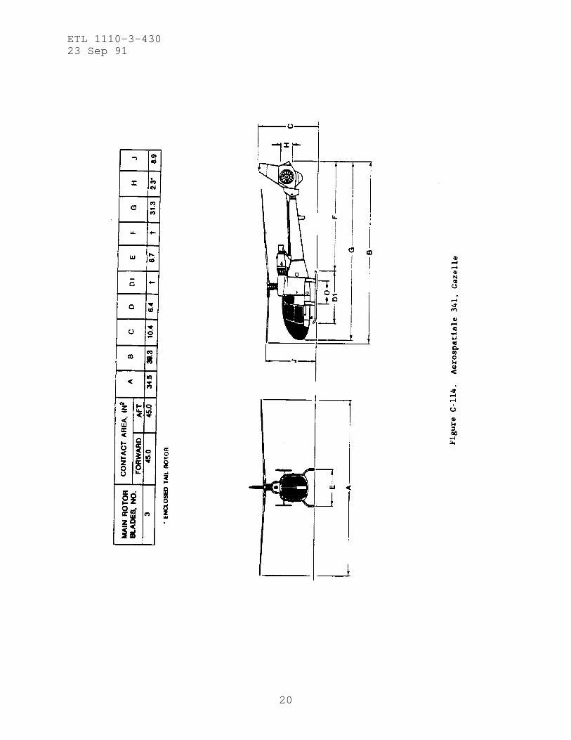
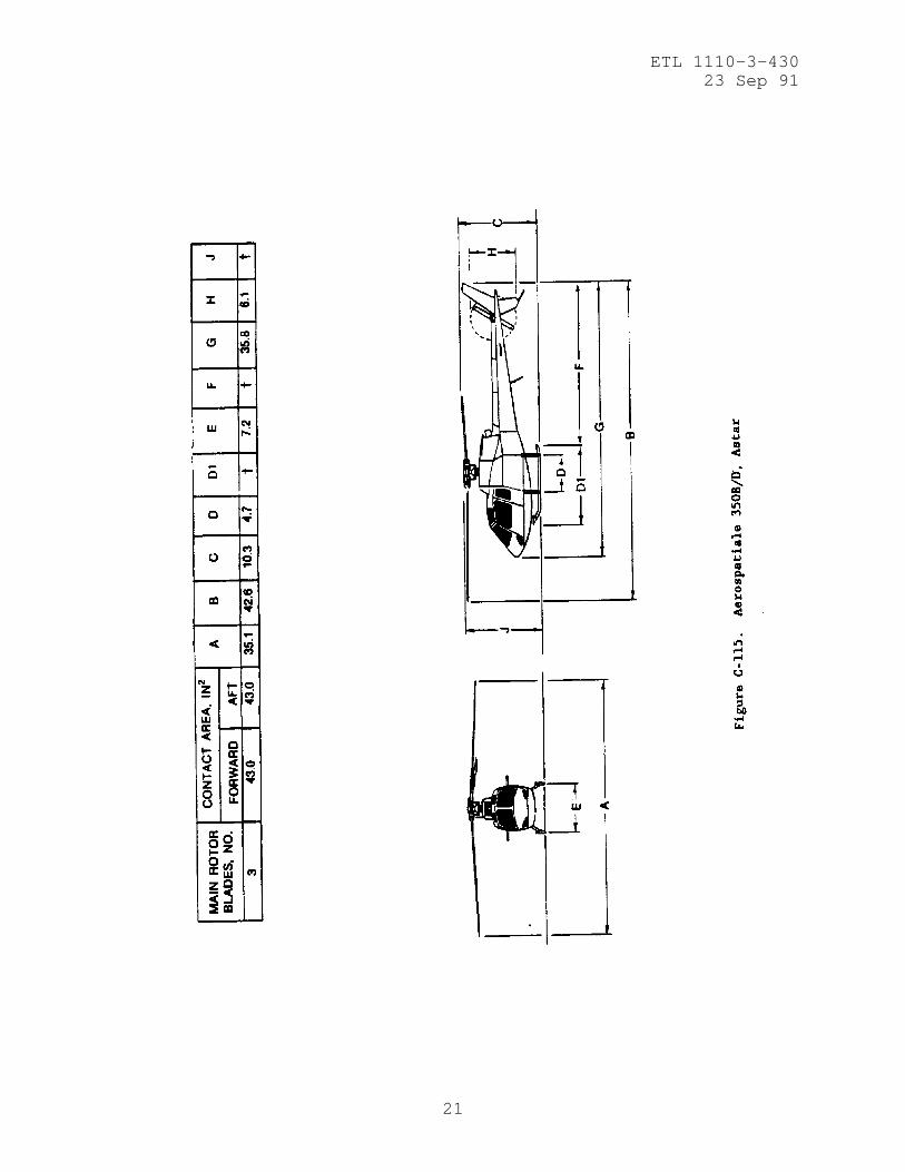
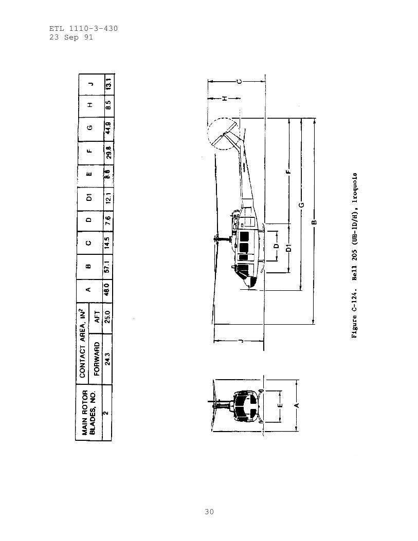
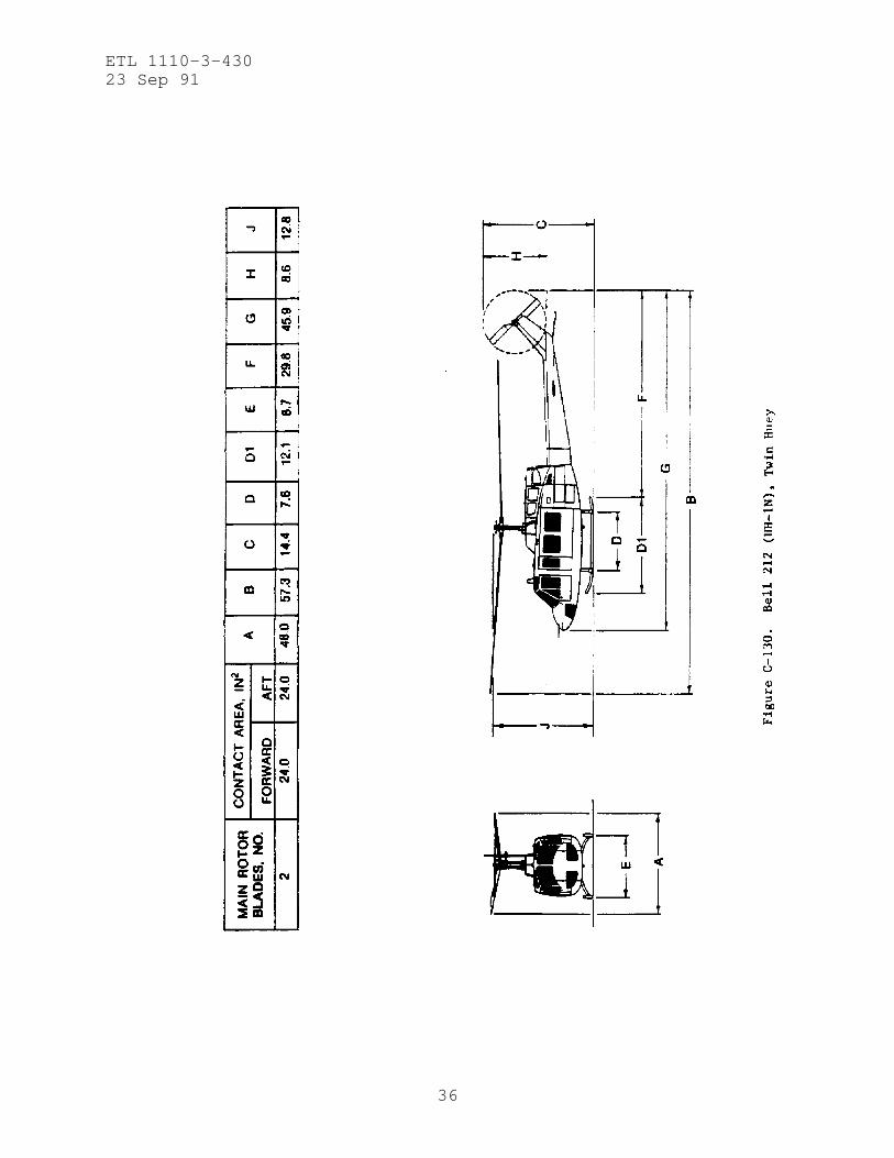
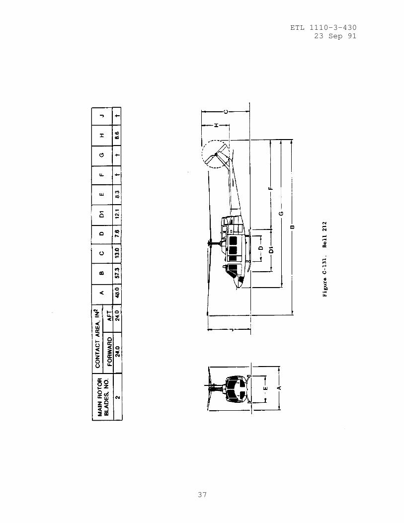
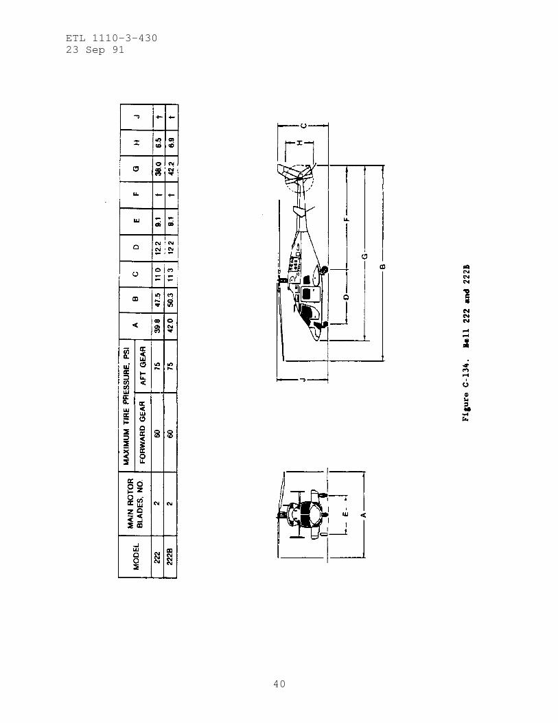
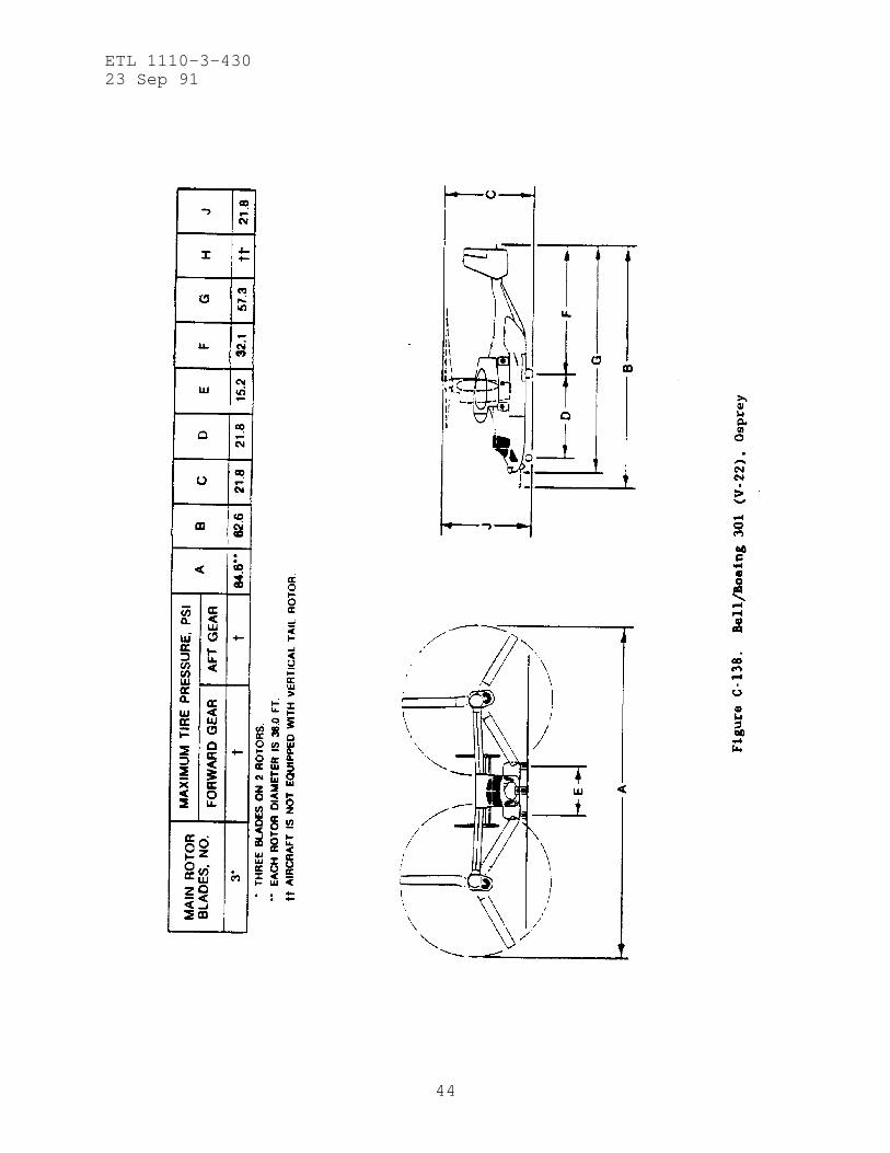
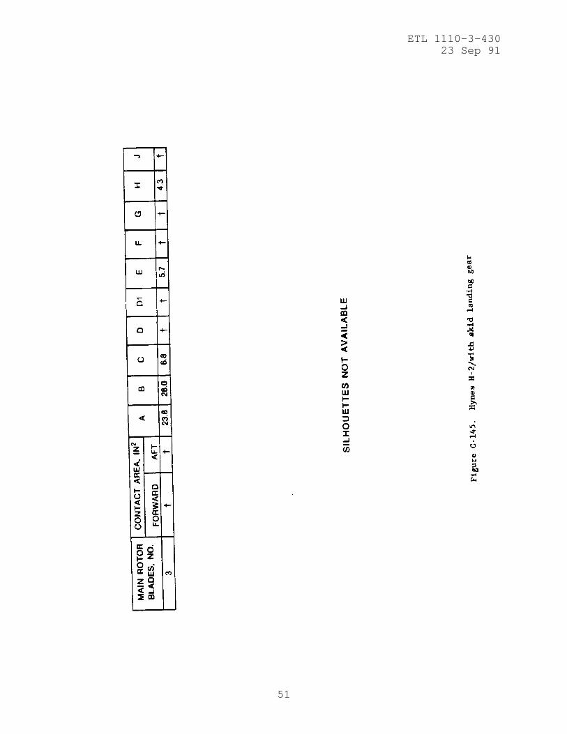
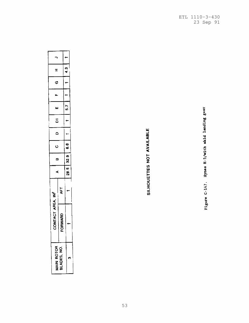
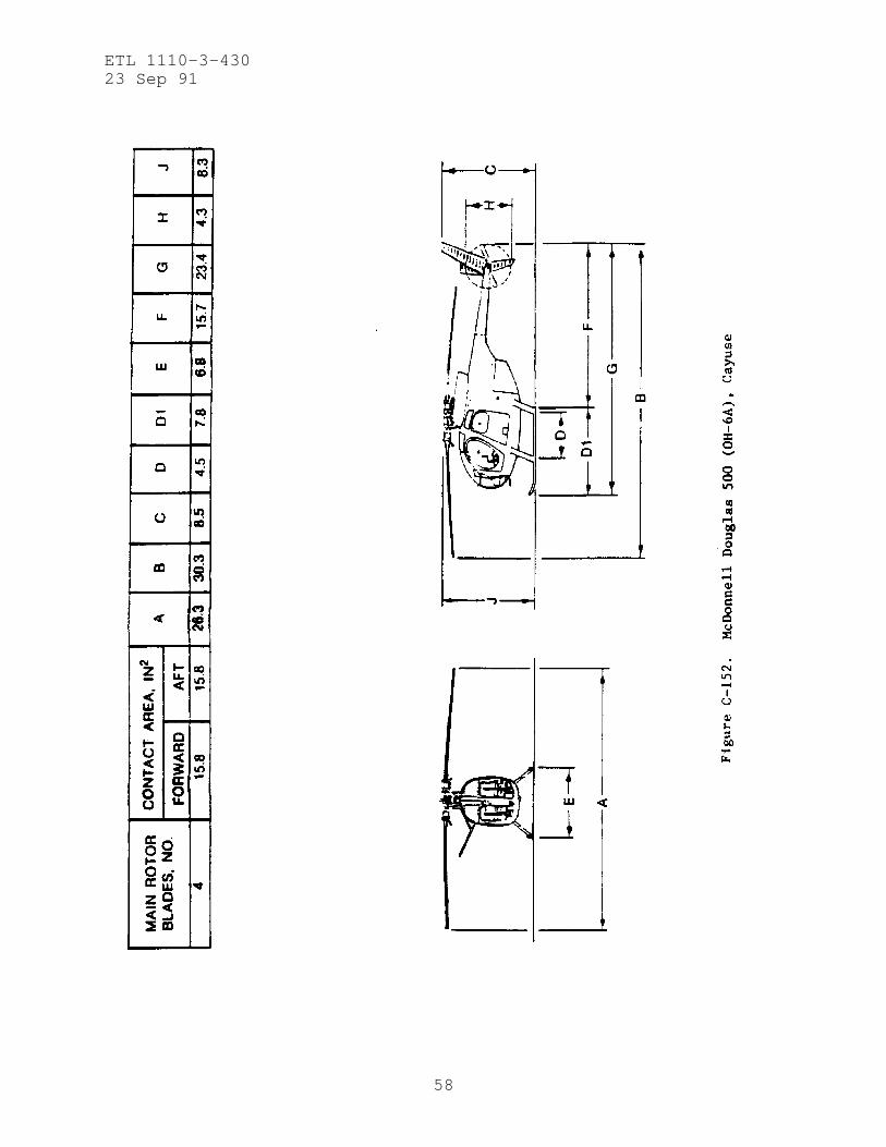
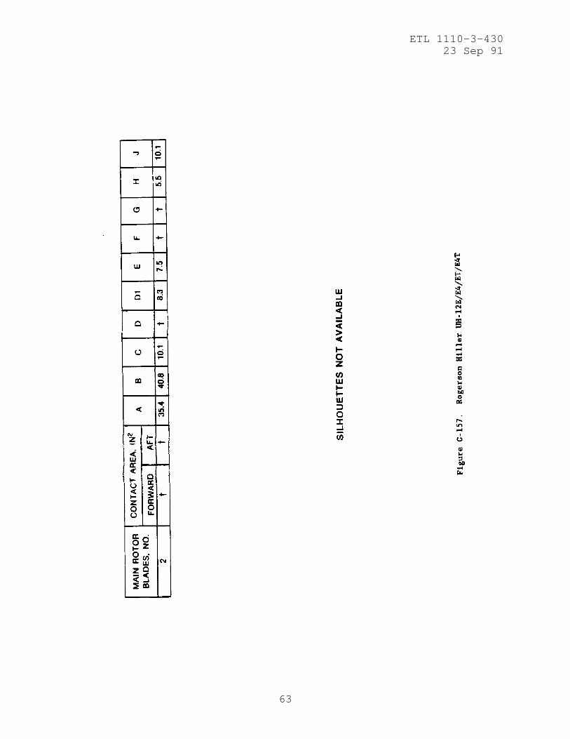
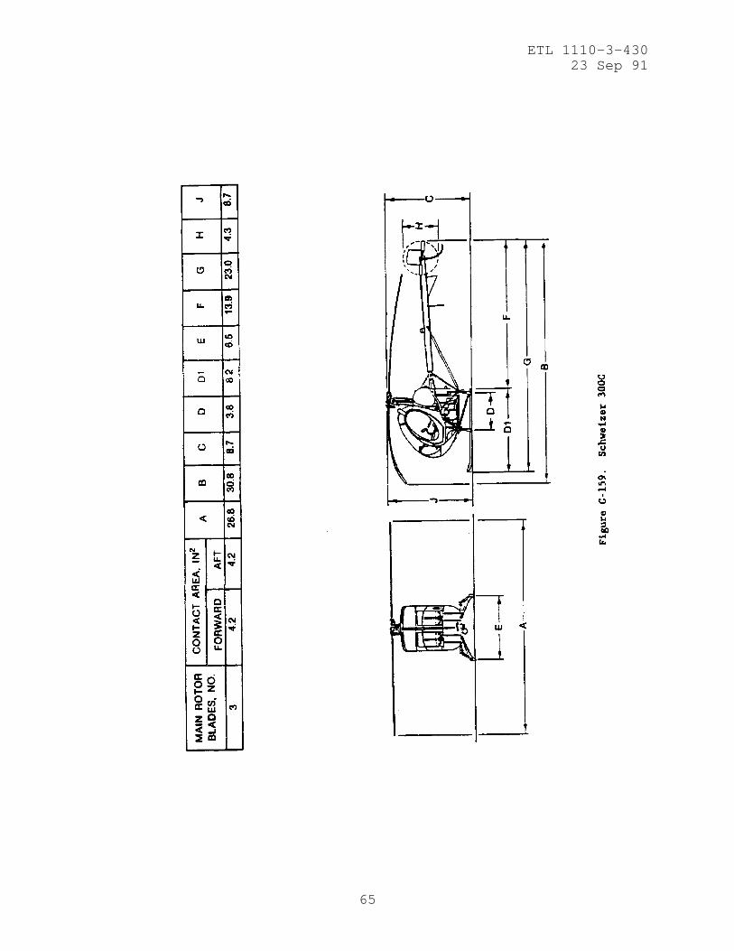
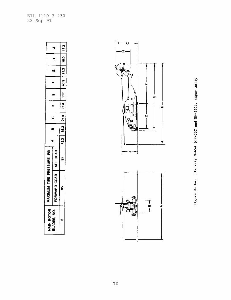
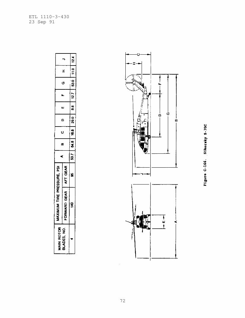
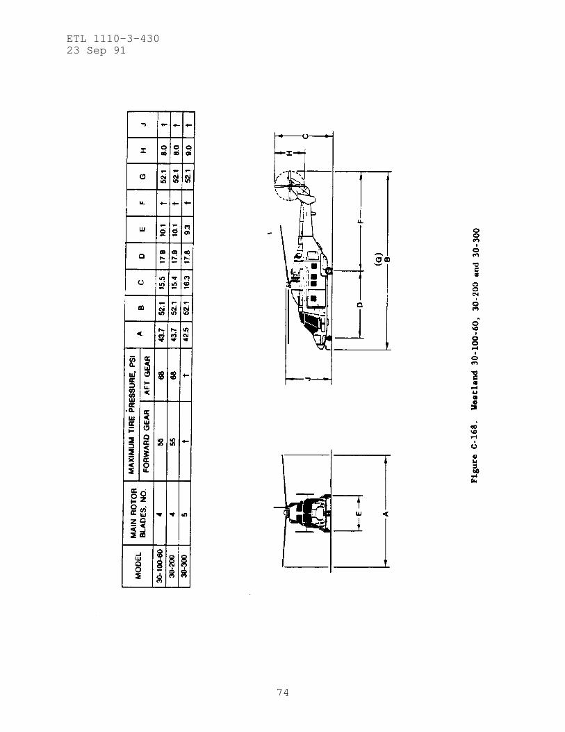
(4) Layout of Mooring Points. Aircraft parking layout shallbe in accordance with TM-5-803-4 with the additional requirementthat the largest diameter rotor blade for the installation*sassigned aircraft be used for locating the mooring points withinthe 80-foot by 80-foot, or 80-foot by 160-foot aircraft parkingareas. Enclosure 2, aircraft geometry, is provided for aircraftparking layout requirements.
e. Mooring Points for New Rigid Pavement Equal to or Greaterthan 6 Inches Thick. Mooring points for new rigid pavementsshould be provided by embedding the mooring devices in freshportland cement concrete. Each aircraft parking position shouldbe provided with mooring points. The layout of points is shown inFigure 1 of Enclosure 1 with mooring points at least 2 feet fromthe new pavement joints. This will require close coordinationbetween the parking plan and the jointing plan. The mooringdevices should be as shown in Figure 3 of Enclosure 1 withpavement reinforcement around the mooring device as shown infigure 4 of Enclosure 1.
ETL 1110-3-43023 Sep 91
5
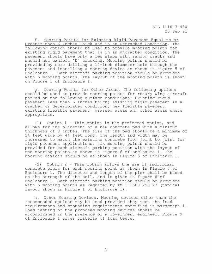
f. Mooring Points for Existing Rigid Pavement Equal to orGreater than 6 Inches Thick and in an Uncracked Condition. Thefollowing option should be used to provide mooring points forexisting rigid pavement that is in an uncracked condition. Thepavement should have only a few slabs with random cracks andshould not exhibit “D” cracking. Mooring points should beprovided by core drilling a 12-inch diameter hole through thepavement and installing a mooring device as shown in Figure 5 ofEnclosure 1. Each aircraft parking position should be providedwith 6 mooring points. The layout of the mooring points is shownon Figure 1 of Enclosure 1.
g. Mooring Points for Other Areas. The following optionsshould be used to provide mooring points for rotary wing aircraftparked on the following surface conditions: Existing rigidpavement less than 6 inches thick; existing rigid pavement in acracked or deteriorated condition; new flexible pavement;existing flexible pavement; grassed areas and other areas whereappropriate.
(1) Option 1 - This option is the preferred option, andallows for the placement of a new concrete pad with a minimumthickness of 8 inches. The size of the pad should be a minimum of24 feet wide by 44 feet long. The length and width may beincreased to match the existing concrete from joint to joint forrigid pavement applications, six mooring points should beprovided for each aircraft parking position with the layout ofthe mooring points as shown in Figure 6 of Enclosure 1. Themooring devices should be as shown in Figure 3 of Enclosure 1.
(2) Option 2 - This option allows the use of individualconcrete piers for each mooring point as shown in Figure 7 ofEnclosure 1. The diameter and length of the pier shall be basedon the strength of the soil, and is given in figure 8 ofEnclosure 1. Each aircraft parking position should be providedwith 6 mooring points as required by TM 1-1500-250-23 (typicallayout shown in Figure 1 of Enclosure 1).
h. Other Mooring Devices. Mooring devices other than therecommended options may be used provided they meet the loadrequirements and grounding requirements specified in paragraph 1.Load testing of the proposed mooring devices should beaccomplished in the presence of a government engineer. Figure 9of Enclosure 1 gives criteria of load tests.

ETL 1110-3-43023 Sep 91
6
i. Grounding Requirements. Grounding requirements formooring devices are as follows. For the drilled pier application,the mooring device is exothermically connected to the reinforcingsteel of the pier (see Figure 7 of Enclosure 1). For the flatslab application the mooring device should be mechanicallyconnected to a 5/8 inch diameter bimetallic copper-covered steelrod that is 6 feet long (see Figure 3 of Enclosure1). These grounding systems normally provide a static groundwith a resistance of less than 10,000 ohms provided the soilresistivity is less than 2,000,000 ohm-centimeters.
7. Guide Specification. A draft guide specification for mooringpoints is provided in Enclosure 3.
8. Implementation. This letter will have routine application asdefined in paragraph 6.c., ER 1110-345-100.
FOR THE COMMANDER:
3 EnclsEncl 1 - Design of U.S. ArmyAirfield Aircraft Mooringand Grounding Points forRotary Wing Aircraft
Encl 2 — Aircraft Characteristicsfor Mooring and Grounding Pointsfor Rotary Wing Aircraft
Encl 3 - Draft Guide Specificationfor Mooring and Grounding Pointsfor Rotary Wing Aircraft at ArmyInstallations

7
Encl 1

ETL 1110-3-43023 Sep 91
8

ETL 1110-3-43023 Sep 91
9

ETL 1110-3-43023 Sep 91
10

ETL 1110-3-43023 Sep 91
11

ETL 1110-3-43023 Sep 91
12

ETL 1110-3-43023 Sep 91
13

ETL 1110-3-43023 Sep 91
14

ETL 1110-3-43023 Sep 91
15

ETL 1110-3-43023 Sep 91
17
Encl 2

ETL 1110-3-43023 Sep 91
18

ETL 1110-3-43023 Sep 91
19
ETL 1110-3-43023 Sep 91
20
ETL 1110-3-43023 Sep 91
21

ETL 1110-3-43023 Sep 91
22

ETL 1110-3-43023 Sep 91
23

ETL 1110-3-43023 Sep 91
24

ETL 1110-3-43023 Sep 91
25

ETL 1110-3-43023 Sep 91
26

ETL 1110-3-43023 Sep 91
27

ETL 1110-3-43023 Sep 91
28

ETL 1110-3-43023 Sep 91
29
ETL 1110-3-43023 Sep 91
30

ETL 1110-3-43023 Sep 91
31

ETL 1110-3-43023 Sep 91
32

ETL 1110-3-43023 Sep 91
33

ETL 1110-3-43023 Sep 91
34

ETL 1110-3-43023 Sep 91
35
ETL 1110-3-43023 Sep 91
36
ETL 1110-3-43023 Sep 91
37

ETL 1110-3-43023 Sep 91
38

ETL 1110-3-43023 Sep 91
39
ETL 1110-3-43023 Sep 91
40

ETL 1110-3-43023 Sep 91
41

ETL 1110-3-43023 Sep 91
42

ETL 1110-3-43023 Sep 91
43
ETL 1110-3-43023 Sep 91
44

ETL 1110-3-43023 Sep 91
45

ETL 1110-3-43023 Sep 91
46

ETL 1110-3-43023 Sep 91
47

ETL 1110-3-43023 Sep 91
48

ETL 1110-3-43023 Sep 91
49

ETL 1110-3-43023 Sep 91
50
ETL 1110-3-43023 Sep 91
51

ETL 1110-3-43023 Sep 91
52
ETL 1110-3-43023 Sep 91
53

ETL 1110-3-43023 Sep 91
54

ETL 1110-3-43023 Sep 91
55

ETL 1110-3-43023 Sep 91
56

ETL 1110-3-43023 Sep 91
57
ETL 1110-3-43023 Sep 91
58

ETL 1110-3-43023 Sep 91
59

ETL 1110-3-43023 Sep 91
60

ETL 1110-3-43023 Sep 91
61

ETL 1110-3-43023 Sep 91
62
ETL 1110-3-43023 Sep 91
63

ETL 1110-3-43023 Sep 91
64
ETL 1110-3-43023 Sep 91
65

ETL 1110-3-43023 Sep 91
66

ETL 1110-3-43023 Sep 91
67

ETL 1110-3-43023 Sep 91
68

ETL 1110-3-43023 Sep 91
69
ETL 1110-3-43023 Sep 91
70

ETL 1110-3-43023 Sep 91
71
ETL 1110-3-43023 Sep 91
72

ETL 1110-3-43023 Sep 91
73
ETL 1110-3-43023 Sep 91
74

ETL 1110-3-43023 Sep 91
75
DESIGN OF U.S. ARMY AIRFIELD AIRCRAFTMOORING AND GROUNDING POINTS FOR ROTARY WING AIRCRAFT
DRAFT GUIDE SPECIFICATION FOR MOORING AND GROUNDING POINTSFOR ROTARY WING AIRCRAFT AT ARMY INSTALLATIONS
*****************************************************************NOTE: This guide specification covers requirements for U S Armyprojects requiring mooring and grounding points for rotary wingaircraft parking aprons and pads. This guide specification is to beused in the preparation of project specifications in accordancewith ETL 1110-3-340.*****************************************************************
PART 1 GENERAL
1.1 SUMMARY (Not Applicable)
1.2 REFERENCES
*****************************************************************NOTE: Issue (date) of references included in projectspecifications should be checked to provide the most currentversion.*****************************************************************
The publications listed below form a part of this specification tothe extent referenced. The publications are referred to in the textby the basic designation only.
AMERICAN SOCIETY FOR TESTING AND MATERIALS (ASTM)
ASTM A 36 (1989) Structural Steel
ASTM A 436 (1984) Austenitic Gray Iron Castings
ASTM A 615 (1987) Deformed and Plain Billet-Steel Barsfor Concrete Reinforcement
ASTM A 616 (1987) Rail-steel Deformed and Plain Bars forConcrete Reinforcement
ASTM A 617 (1987) Axle-Steel Deformed and Plain Bars forConcrete Reinforcement
ASTM B 8 (1986) Concentric-Lay-Stranded Copper Conductors,Hard, Medium-Hard, or Soft
Encl 3

ETL 1110-3-43023 Sep 91
76
ASTM B 371 (1984a) Copper-Zinc-Silicon Alloy Rod
ASTM C 94 (1990) Standard Specification for Ready MixConcrete
AMERICAN WELDING SOCIETY (AWS)
AWS Dl.l (1988) Structural Welding Code - Steel
AWS D1.4 (1979) Structural Welding Code - Reinforcingsteel
UNDERWRITERS LABORATORIES (UL)
UL 467 (Nov 22, 1984; 6th Ed; Rev thru Nov 14, 1986)Grounding and Bonding Equipment
U.S. ARMY CORPS OF ENGINEERS, WATERWAYS EXPERIMENT STATION (CEWES)
CEWES CRD C-300 (1988) Handbook for Concrete and Cement:Membrane-Forming Compounds for Curing Concrete
1.3 SUBMITTALS
*****************************************************************NOTE: Submittals must be limited to those necessary for adequatequality control. The importance of an item in the project should beone of the primary factors in determining if a submittal for theitem should be required.*****************************************************************
The following shall be submitted in accordance with SectionSUBMITTALS:
*****************************************************************If concrete is supplied by another specification section, acertificate of compliance should not be required here. Edit thefollowing paragraph accordingly.*****************************************************************
SD-76, Certificates of Compliance
Manufacturer*s certificates attesting that the mooring devices,grounding rods and concrete meet the specified requirements.

ETL 1110-3-43023 Sep 91
77
SD-90, As-Built Drawings
Drawings that provide current factual information includingdeviations from, and amendments to the drawings and changes in thework, concealed and visible.
*****************************************************************The intent of this specification is to provide mooring points withresistance to ground of no more than 10,000 ohms. The itemsspecified will provide that if the resistance of the surroundingsoil or rock is less than 2,000,000 ohm-centimeters.*****************************************************************
PART 2 PRODUCTS
2.1 MATERIALS
2.1.1 General Requirements
No combination of materials shall be used that forms anelectrolytic couple of such nature the corrosion is accelerated inthe presence of moisture unless moisture is permanently excludedfrom the junction of such metals.
2.1.2 Mooring Devices
Mooring devices shall be cast in ductile iron 80-55-06 conformingto ASTM A 436. The device shall be as shown in the contractdrawings. The contractor shall submit certificates of compliance onthe devices.
2.1.3 Grounding Rods
Grounding rods shall conform to UL 467 and shall be made of copper-clad steel. The rods shall not be less than 5/8 inch in diameterand not less than 6 feet long, pointed at the bottom end andthreaded with a 5/8 inch diameter American Standard Rolled threadat the top for attachment to the mooring device. The coppercladding shall conform to the applicable requirements of ASTM B 371(Copper Alloy UNS No*s. c 69400, c 69430, c 69440 or c 69450). Thecopper cladding shall not be less than 0.010 inches thick at anypoint and shall comply with adherence requirements in paragraph10.7 and the banding requirements in paragraph 10.8 of UL 467. Thecopper-clad steel rods shall conform to ASTM A 36 steel. Thecontractor shall submit certificates of compliance on the groundingrods.

ETL 1110-3-43023 Sep 91
78
2.1.4 Copper Conductors
Copper conductors shall be bare # 4 copper wire conforming to ASTMB 8. The contractor shall submit certificates of compliance on thecopper conductors.
*****************************************************************NOTE: Designer should edit the following paragraph to provide thissection with concrete.*****************************************************************
2.1.5 Concrete
*****************************************************************NOTE: ASTM C 94 is set up to use Type I cement. If other types ofcement are required because of site conditions, the designer shouldspecify the proper cement type. The 6000 psi compressive strengthconcrete is required f or drilled piers and f or mooring pointinstallation is existing rigid pavements. New rigid pavement withflexural strength of 500 psi or greater should be adequate formooring point installation.*****************************************************************
Concrete shall be in accordance with (Section; Concrete Pavementsfor Roads and Airfields] (ASTM C 94). The concrete shall be airentrained and have a minimum compressive strength of 6000 psi. Theconcrete shall have the following properties: Nominal maximumaggregate size of 1 inch, air content of 6%, and a maximum slump of2 inches. The contractor shall submit certificates of compliance ofthe concrete mix.
2.1.6 Reinforcing Steel
Reinforcing steel shall conform to (ASTM A 615) (ASTM A 616] [ASTMA 617) Grade 36. Steel shall be welded into cages in accordancewith AWS Dl.4 and inserted securely in the piers, in position andalignment, as shown, prior to concrete placement. The contractorshall submit certificates of compliance of the reinforcing steel.
PART 3 EXECUTION*****************************************************************Note: Types of mooring point installations not needed should beedited out.*****************************************************************
3.1 MOORING POINTS IN NEW RIGID PAVEMENTS OR CONCRETE PADS

ETL 1110-3-43023 Sep 91
79
3.1.1 Location
The mooring device and the attached grounding rod shall beinstalled within plus or minus 2 inches of the location shown onthe Contract Drawings. The top of the mooring device shall be setwithin 1/4 inch of the plan pavement surface elevation, but nothigher than the pavement surface.
3.1.2 Installation
The mooring device shall be installed prior to placement of theconcrete pavement. Concrete and reinforcement shall be placed inaccordance with specification section (____________________). Handfinishing of the concrete around the mooring devices shall be keptto a minimum.
3.2 MOORING POINTS IN EXISTING RIGID PAVEMENTS
3.2.1 General
The mooring points shall be installed in 12 plus or minus 1/2 inchdiameter holes cored through the pavement.
3.2.2 Location
The core holes shall be drilled within plus or minus 1 and 1/2inches of the location shown in the Contract Drawings. The mooringdevice and attached grounding rod shall be installed within plus orminus 1/2 inch of the center of the core hole. The top of themooring device shall be installed within 1/4 inch of thesurrounding pavement surfaces, but not higher.
3.2.3 Installation
The holes shall be cored using rotary, non-percussion drillingtechniques. The sides of the core hole shall be perpendicular tothe pavement surface. Once the pavement is cored the base courseshall be excavated as shown in the Contract Plans. The sides ofthe core hole shall then be cleaned of laitence and roughened bysand blasting. The mooring device shall be screwed on to thegrounding rod and tightened sufficiently to allow installation andmake electrical contact. The rod and mooring device shall beinstalled in the core hole by pushing or driving the rod throughthe pavement base courses and subgrade. The installation techniquechosen by the contractor shall not damage the mooring device orgrounding rod. The contractor shall then place the concrete aroundthe mooring device in two or more lifts. The first lift should beplaced to within 5 inches of the pavement surface and thoroughly

ETL 1110-3-43023 Sep 91
80
consolidated by spud vibrators. The second lift should then beplaced and also consolidated by internal vibration. The surface ofthe concrete shall then be finished and textured to match theadjacent pavement surface and elevation. White pigmented curingcompound meeting the requirements of CRD C-300 shall then beuniformly applied at a coverage of not more than 200 square feetper gallon.
3.2.4 Cleanup
The contractor shall control all operations to minimize the amountof dust, dirt, debris and latency in the work area. The contractorshall clean all dirt, dust, debris, or laitence from coring orconcreting operations, from the pavement surfaces prior to finalacceptance.
3.3 MOORING POINTS INSTALLED IN DRILLED PIERS
3 3.1 General
Excavation of piers shall be performed so that reinforcing steeland concrete placement is a continuous operation performed the sameday that the excavation is completed. Excavations shall not be leftopen overnight. Concrete shall be placed within 3 hours afterapproval of the completed excavation. Pier drilling equipment shallhave the minimum torque capacity and downward force capacity forthe contract site conditions.
3.3.2 Government Inspection
The Contracting Officer will inspect each drilled pier excavation.Concrete shall not be placed until the excavation has been approvedby the Contracting Officer. The Contractor shall furnish theContracting Officer all necessary equipment required for properinspection of drilled pier excavations.
3.3.3 Installation
3.3.3.1 Excavate piers to established depths and dimensionsshown. Piers shall be core drilled through pavements. Bottoms ofpiers shall be cleaned of loose or soft material and leveled.Excavated material shall be disposed of in accordance with Section02210 GRADING (EARTHWORK).
3.3.3.2 In drilling piers, the surrounding base courses, subgrade,and soil shall be adequately and securely protected against cave-ins, displacement of the surrounding earth, and retention of groundwater by means of temporary steel casings. Casings shall have

ETL 1110-3-43023 Sep 91
81
outside diameters not less than the indicated shaft sizes and shallbe a minimum of ¼-inch thick. Steel casings shall be withdrawn, asthe concrete is being placed, maintaining sufficient head ofconcrete within the cawing to prevent extraneous material fromfalling in from the sides and mixing with the concrete. Casings maybe jerked upward a maximum of 4 inches to break the bottom seal butthereafter remove with a smooth, continuous motion.
3.3.3.3 The inside of steel casings shall be thoroughly cleanedand oiled before reuse.
3.3.3.4 Water that flows into the excavations shall becontinuously removed and all water shall be removed from theexcavation bottom, to the extent possible, prior to concreteplacement. The maximum permissible depth of water will be 2 inches.In the event of a severe water condition that makes it impossibleor impractical to dewater the excavation, concrete shall be placedusing underwater tremie after water movement has stabilized.
3.3.3.5 Concrete shall be continuously placed by methods thatinsure against segregation and dislodging of excavation sidewallsand shall completely fill the shaft. Concrete shall be placed bypumping or drop chutes in dry holes and by tremie or pumping in wetholes. The discharge shall be kept a minimum of 1 foot below thefresh concrete surface during placement. Concrete placement shallnot be interrupted in any pier for more than 30 minutes. Concreteshall be vibrated for the full height of the pier.
3.3.3.6 Any pier out of center or plumb beyond the tolerancespecified shall be corrected as necessary to comply with thetolerances and the Contractor shall bear any cost of correction.Cross sections of shafts shall not be less than design dimensions.Piers shall be installed with top location deviating a maximum of2 inches from centerline locations.
3.3.3.7 The Contractor shall replace at no additional cost to theGovernment, piers found out of tolerance or, found inadequatebecause of improper construction procedures.
3.3.3.8 The Contractor shall provide protection around top of theexcavation to prevent debris from being dislodged into theexcavation and concrete.