distributed personal authentication systems (dp as)
TRANSCRIPT
Distributed Personal Authentication Systems (DP AS)
By
Mohd Shahadan Bin Mokhtar
Dissertation submitted in partial fulfillment of
the requirements for the Bachelor ofEngineering (Hons)
(Electrical Engineering)
JUNE2008
Universiti Teknologi PETRONAS Bandar Seri Iskandar 31750 Tronoh Perak Darul Ridzuan

Dedicated to
My parents who always give encouraging words
Hj. Mokhtar Bin Hj. Mohamed
Hjh. Nor Asiah Binti Hj. Aris Jamali
My siblings who have always been my pride and joy
Umairah Arina Binti Hj. Mokhtar
Umairah Izzati Binti Hj. Mokhtar
My friend & other half wham I always rely on
Miss Nur Syahadah Binti Mohd Sapli
My dear friend who always listens
Ms Siti Hawa Hj Tahir
All friends with whom I share five wonderfUl years of my life in UTP
Thank you all for the great gifts that each of you have bestowed upon me
-activell-
http://shahadan-activell. blogspot. com
DISTRIBUTED PERSONAL AUTHENTICATION SYSTEMS (DPAS)
By
MOHD SHAHADAN BIN MOKHTAR
FINAL PROJECT REPORT
Submitted to the Electrical & Electronics Engineering Programme
in Partial Fulfillment of the Requirements
for the Degree
Bachelor of Engineering (Hons)
(Electrical & Electronics Engineering)
Universiti Teknologi PETRONAS
Bandar Seri Iskandar
31750 Tronoh
Perak Darul Ridzuan
© Copyright 2008
by
MOHD SHAHADAN BIN MOKHTAR, 2008
11

CERTIFICATION OF APPROVAL
DISTRIBUTED PERSONAL AUTHENTICATION SYSTEMS (DPAS)
Approved:
by
Mohd Shahadan Bin Mokhtar
A project dissertation submitted to the
Electrical & Electronics Engineering Programme
Universiti Teknologi PETRONAS
in partial fulfillment of the requirement for the
Bachelor of Engineering (Hons)
(Electrical & Electronics Engineering)
DR MUMTAJ BEGAM
Project Supervisor
UNIVERSITI TEKNOLOGI PETRONAS
TRONOH, PERAK
June 2008
lll

CERTIFICATION OF ORIGINALITY
This is to certify that I am responsible for the work submitted in this project, that the
original work is my own except as specified in the references and acknowledgements,
and that the original work contained herein have not been undertaken or done by
uuspecified sources or persons.
Mohd Shahadan Bin Mokhtar
IV

ABSTRACT
Authentication systems, especially in forensic areas are essential towards this modern
life nowadays. It is also giving human an opportunity to study and learn more about
remote enviromnent. Besides that, this authentication technology also helps various
fields to perform their special task that cannot be achieved by human. The use of
smart authentication technology replacing an individual is a very exciting field to be
explored. This project presents the use of the forensic application namely fingerprint
recognition systems and how its automatic features help to perform its task using
Digital Image Processing techniques and MATLAB coding. The objective of this
project is to build a simple prototype of Distributed Personal Authentication Systems
(DPAS) that can perform a basic recognition process, enhanced with the ability to
send a signal to communication cable for further development in the tuture. The
project undergoes several processes of designing and modifying before it reaches to
the prototype state. As the result, the simulation was able to perform the
authentication and recognition operation using simple programming language which
is MA TLAB coding.
v

ACKNOWLEDGEMENTS
I would like to express my appreciation to Universiti Teknologi Petronas (UTP) for
providing good facilities for me to carry out this project. My deepest gratitude also
goes to my supervisor, Dr. Mumtaj Begam from Electrical Electronics Department,
without whom, I may not be able to do this project. Your constant guidance and
coaching have helped me a lot, Madam. Thank you very much.
Not to forget my fellow friends who help in gaining information and knowledge on
the course and as well as things I have never studied before. I also want to thank my
family for the moral support and keep on reminding me to give my best for the
project. Special thanks go to Miss Nur Syahadah Mohd Sapli for her words and
encouragement towards the project.
Finally, I would like to thank all who have, directly and indirectly, supported and
helped me throughout the project.
VI
TABLE OF CONTENTS
LIST OF FIGURES ..................................................................................................... ix
LIST OF TABLES .............................................................................. x
LIST OF ABBREVIATIONS ...................................................................................... xi
CHAPTER I INTRODUCTION .................................................................................. !
1.1 Background of Study ........................................................................ I
1.2 Problem Statement ........................................................................... 2
1.3 Objective and Scope ......................................................................... 3
CHAPTER 2 LITERATURE REVIEW AND THEORY ........................................... .4
2.1 DPAS ................................................................................................ 4
2.2 Digital Image Processing ................................................................. 4 .
2.3 Biometric .......................................................................................... 5
2.3.1 Automated Use ........................................................................ 6
2.3.2 Physiological or Behavioral Characteristics ............................ 6
2.4 Fingerprint ........................................................................................ 6
2.4.1 Fingerprint identification ......................................................... 7
2.5 Car Ignition System .......................................................................... 8
2.5.1 Battery ...................................................................................... 9
2.5.2 Ignition Switch ......................................................................... 9
2.5.3 Neutral Safety Switch ............................................................ I 0
2.5.4 Starter Motor .......................................................................... 10
2.6 NPN Type Transistor as a Switch .................................................. II
2.7 DPAS Model .................................................................................. 11
CHAPTER 3 METHODOLOGY ............................................................................... 13
3.1 Sequence of Methodology .............................................................. 13
3.1.1 Stage I ................................................................................... 14
3.1.2 Stage 2 ................................................................................... 14
3.2 Computer Vision and Image Processing Methodology .................. 15
3.2.1 Fingerprint Image Processing using CVID Methods ............. 16
3.2.2 Histogram Equalization ......................................................... 17
3.2.3 Tools ...................................................................................... 19
3.3 Project Development ...................................................................... 20
VII
CHAPTER 4 RESULT AND DISCUSSION ............................................................. 22
4.1 FINDINGS ..................................................................................... 22
4.2 MATLAB Coding .......................................................................... 24
4.3 Result. ............................................................................................. 29
4.4 Discussion ...................................................................................... 3 7
CHAPTER 5 CONCLUSION AND RECOMMENDATION .................................... 38
5.1 Conclusion ...................................................................................... 38
5.2 Recommendation ............................................................................ 38
REFERENCES ............................................................................................................ 40
APPENDICES ............................................................................................................ 41
Appendix A gannt chart ....................................................................... 42
Appendix B camera specification ......................................................... 43
V111
LIST OF FIGURES
Figure 1 : Original Image .............................................................................................. 5
Figure 2 : Sharpened Image ........................................................................................... 5
Figure 3: A fmgerprint image acquired by an Optical Sensor ...................................... 6
Figure 4 : Minutia .......................................................................................................... 7
Figure 5 : Car Ignition Systems ............................................ : .. ······································ 8
Figure 6: DPAS Model.. ............................................................................................. l2
Figure 7: Sequence of Methodology .......................................................................... 13
Figure 8: CVID Technique ................................................................................................. l6
Figure 9 : The Original histogram of a fmgerprint image .................................... .17
Figure 10 : Histogram after the Histogram Equalization ............................................ 17
Figure 11 : Before Histogram Equalization ...................................................................... 18
Figure 12: After Histogram Equalization ...................................................... .l8
Figure 13 : Project Development Flow Chart ............................................................. 21
Figure 14 : Finger Print Sample .................................................................................. 22
Figure 15 : Output from Image Acquisition ................................................................ 30
Figure 16 : Enlarged Image ......................................................................................... 30
Figure 17: Image Information Tool ............................................................................. 31
Figure 18 : Gray image ................................................................................................ 32
Figure 19: Image Information for Gray Image ........................................................... 32
Figure 20 : Output from Image Histogram .................................................................. 34
Figure 21 : Image Detail for Figure 20 ....................................................................... 34
Figure 22 : Filtered Image ........................................................................................... 35
Figure 23 : Image Information for the Filtered Image ................................................ 35
Figure 24 : Output from Feature Extraction ................................................................ 36
IX

LIST OF TABLES
Table I : Price Listing ................................................................................................. 19
Table 2 : Fingerprint Capture Types [2] ...................................................................... 23
X

LIST OF ABBREVIATIONS
CVID Computer Vision and Image Data
DPAS Distributed Personal Authentication Systems
PC Personal Computer
PIN Personal Identification Numbers
UTP Universiti Teknologi PETRONAS
XI
1.1 Background of Stndy
CHAPTER I
INTRODUCTION
Authentication is the fundamental element of human interaction with
computers. Traditionally, authentication by using the computer is closely related with
the usage of passwords and personal identification numbers (PINs) and it seems to
dominate the market for years until the coming of the new technology which uses
Biometrics methods. Biometric is the term of applying statistic and mathematical
techniques to data analysis problem in biological sciences (1]. Moreover, Biometric is
also referred to as the emerging field of technology devoted to identification of
individual using biological traits [2]. Biometric world consists of several portions
such as face, voice, fingerprint, signature, and many more. But, throughout the
project, focuses will be on the fingerprint method and the study of car ignition
systems as pre-application of the end-prototype.
The unique traits of the method will be the main advantage and challenges to
integrate both systems, Central Locking Systems and authentication systems. Besides,
other advantages of using Biometrics are reduced cost, increased accuracy, and
increase ease of use. All those criteria have combined to make biometrics an
increasingly feasible solution for securing access in many applications [1].
The idea of the research is to apply the biometrics techniques into real working
environment for authentication purposes and defines how biometrics deployments can
be privacy enhancing and privacy invasive.
1

1.2 Problem Statement
The cases of car that are stolen keep on increasing day by day and it gives a big
question mark on the reliability of the conventional security system attached to our
cars. Car owners, manufacturers and even government put very strong attention to
overcome the problem and one of the suitable solutions is to implement smart
authentication systems such as biometric methods to the vehicles [3]. The existence
of the frequently used authentication technologies such as passwords and PINs bring
secure access to personal information data, PCs and many applications. However, all
those techniques have a number of problems that question their suitability for modern
applications, particularly high-security applications such as access to automobile and
military devices [I]. As the result, scientists and engineers work together to take
advantage of using Biometric method as the authentication alternatives [!]. In this
project, finger print method will be highlighted throughout the assignment and
intensive effort should be put to ensure the effectiveness of the smart authentication
systems and benefited the community as the main target at the end of the
implementation.
The significance of the project is relatively coherent with the objectives of this
research works which are to study the basic implementation of Computer Vision and
Image Processing techniques to build a DP AS prototype and enhance the security
level of the real world applications, increase convenience of the systems compared to
traditional methods and improve the accountability of the distributed personal
authentication systems. At the end of the day, hopefully the project gives good
contribution in order to tackle theft of identity, stolen car problem and gives people a
huge comfort zone to run daily life peacefully.
2

1.3 Objective and Scope
The objective of this project is to develop a simulation of the Distributed
Personal Authentication Systems (DP AS) that can snap a picture and compare with a
set of database pictures using Computer Vision and Image Processing techniques.
This simulation is also equipped with automatic features that are capable to give a
valuable signal to communication cable which is attached to car ignition systems
obstacle. The main maneuver for the project is MATLAB coding and digital camera
in connection to the personal computer (PC). The minor objective of the project is to
study the car ignition systems as the pre-application model for further development of
the whole project. As the scope of the project are:-
I. Research and Analysis- to research and analyze the topics background to
collect information and ideas.
2. Design Concept- to design and analyze several potential design that suit
the prototype requirement and the feasibility of the design regarding the
cost, availability of materials and time constraint.
3. Building the Prototype - to build the prototype starting with the
construction of the thrusters, the body-frame and the maneuverability
capability of the prototype.
4. Testing- to test the prototype functionality and durability.
5. Product Enhancement - to enhance the prototype with appropriate
functionality to meet requirement given.
The allocated time-frame of approximately one year is sufficient to carry out the
entire task required in the project. With well-planned schedule and consistency of
asking opinions and guidance from supervisor and field-related-person would helps in
archiving the success in this project. Appendix A summarized the allocated time
frames for all tasks performed throughout the two semesters in a Gantt chart.
3
2.1 DPAS
CHAPTER2
LITERATURE REVIEW AND THEORY
Distributed Personal Authentication Systems (DP AS) is the accepted name
for this whole project. DP AS consists of digital camera and personal computer as the
main maneuver throughout the project and also equipped with communication cable
(RS 232) and car ignition systems for the research purposes. They are linked together
to stand on their own as recognition device to interpret data given by an individual.
For the purpose of the project, DPAS is considerable as the replacement of car keys to
activate car ignition systems.
2.2 Digital Image Processing
Digital image processing is basically done to satisfy one or both conditions
which are to give a better human perception or render the image more suitable for
machine perception. This involves using a computer to change the nature of the
image. There are many procedures to satisfy the conditions, and these procedures are
called digital image processing techniques. It is done because humans generally
would prefer a sharper, clearer and more detailed image so that it is more accessible
for the human and machines prefer a simple and less messy and would take up lesser
memory so that it is easier to compute for the machine.
There are several techniques which could be used. Some of them include edge
enhancement, which make the image looks sharper. For example, take Figure 1, and
Figure 2 and compare both pictures.
4
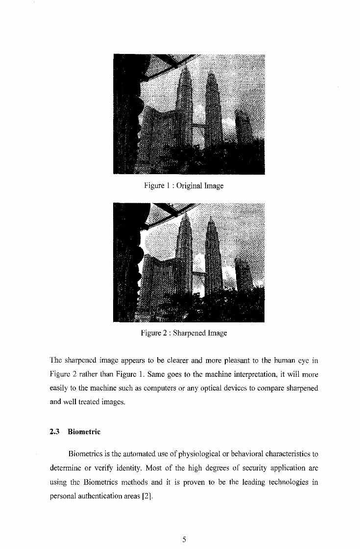
Figure I : Original Image
Figure 2 : Sharpened Image
The sharpened image appears to be clearer and more pleasant to the human eye in
Figure 2 rather than Figure I. Same goes to the machine interpretation, it will more
easily to the machine such as computers or any optical devices to compare sharpened
and well treated images.
2.3 Biometric
Biometrics is the automated use of physiological or behavioral characteristics to
determine or verify identity. Most of the high degrees of security application are
using the Biometrics methods and it is proven to be the leading technologies in
personal authentication areas [2].
5
2.3.1 Automated Use
Biometrics methods are used to verify or determine identity through behavioral
or physiological characteristics. Since the process is automated, biometric
authentication generally requires only a few seconds, and biometrics systems are able
to compare thousands of records per second [I, 2, 3].
2.3.2 Physiological or Behavioral Characteristics
Biometrics is based on the measurement of distinctive physiological and
behavioral characteristics. Common example of physiological biometrics are finger
scan, facial scan, iris-scan and hand scan. They are basically examined by direct
measurement of a part of the human body while voice and signature are considered as
indirect measurement of human body. This is because they receive data derived from
an action and not from physiological or behavioral characteristic [2].
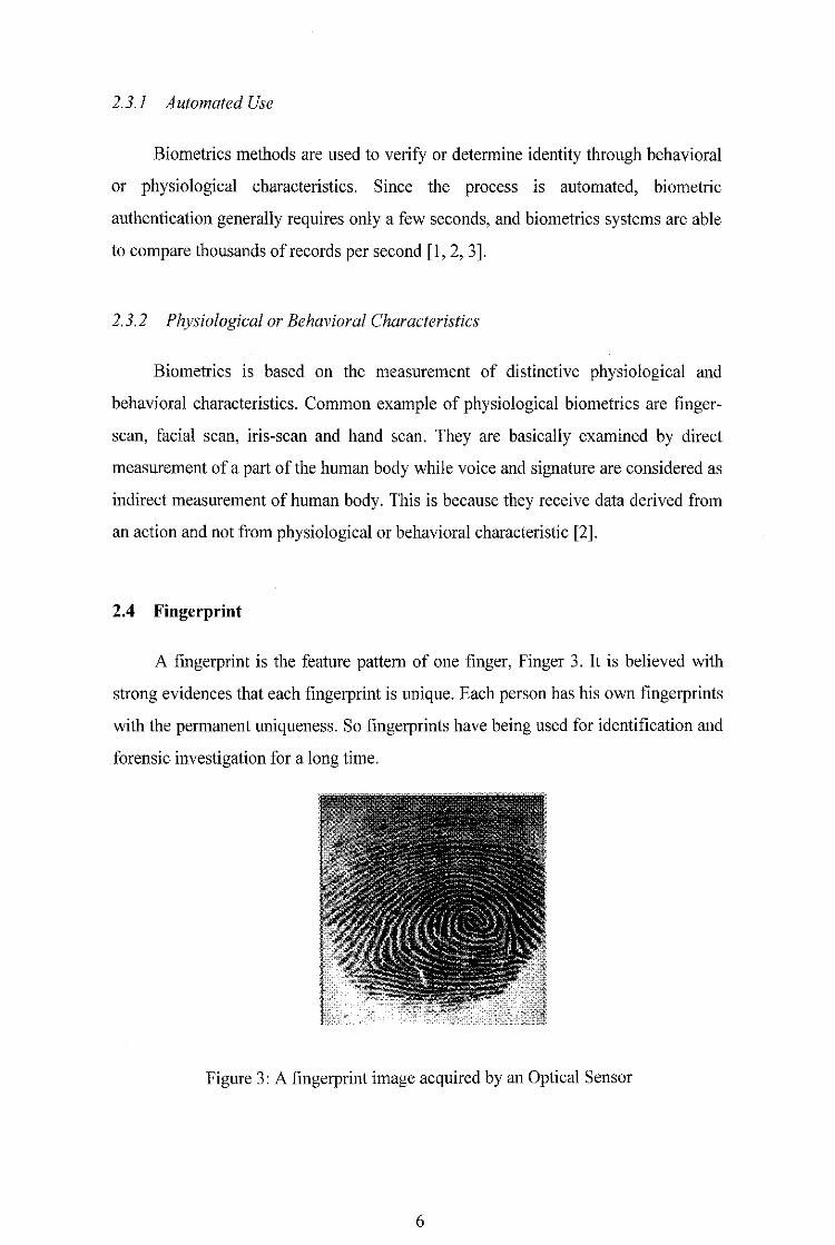
2.4 Fingerprint
A fingerprint is the feature pattern of one finger, Finger 3. It is believed with
strong evidences that each fingerprint is unique. Each person has his own fingerprints
with the permanent uniqueness. So fingerprints have being used for identification m1d
forensic investigation for a long time.
Figure 3: A fingerprint image acquired by an Optical Sensor
6
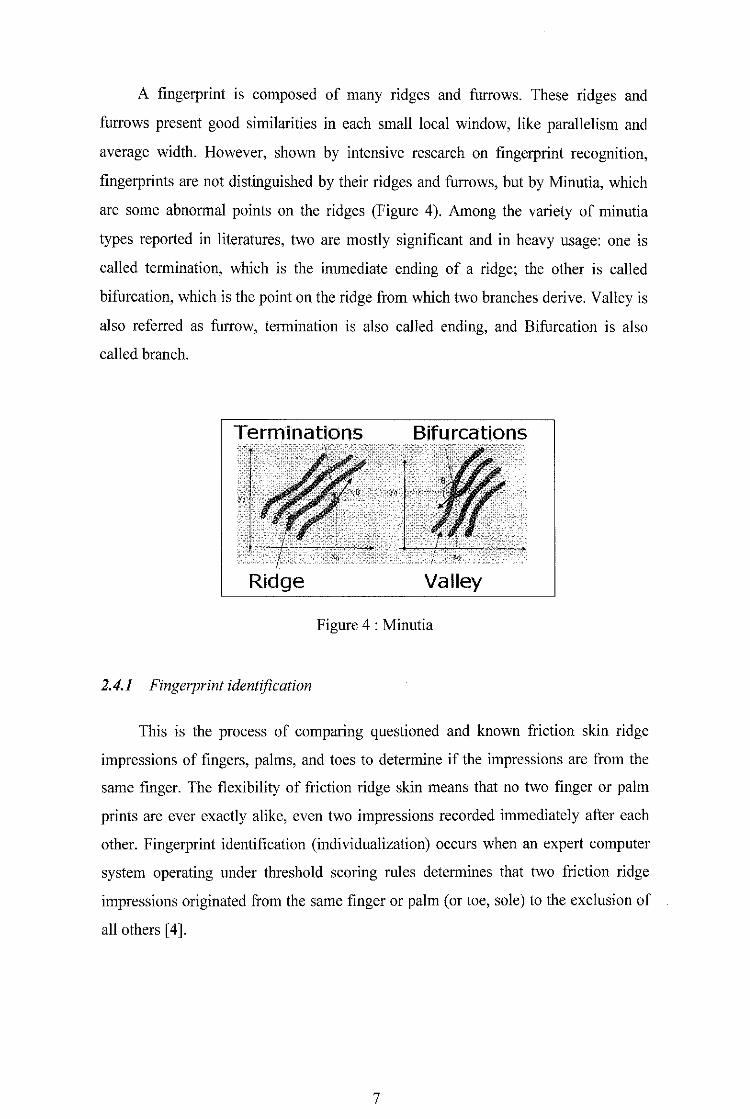
A fingerprint is composed of many ridges and furrows. These ridges and
furrows present good similarities in each small local window, like parallelism and
average width. However, shown by intensive research on fingerprint recognition,
fingerprints are not distinguished by their ridges and furrows, but by Minutia, which
are some abnormal points on the ridges (Figure 4). Among the variety of minutia
types reported in literatures, two are mostly significant and in heavy usage: one is
called termination, which is the immediate ending of a ridge; the other is called
bifurcation, which is the point on the ridge from which two branches derive. Valley is
also referred as furrow, termination is also called ending, and Bifurcation is also
called branch.
Ridge Valley
Figure 4 : Minutia
2.4.1 Fingerprint identification
This is the process of comparing questioned and known friction skin ridge
impressions of fingers, palms, and toes to determine if the impressions are from the
same finger. The flexibility of friction ridge skin means that no two finger or palm
prints are ever exactly alike, even two impressions recorded immediately after each
other. Fingerprint identification (individualization) occurs when an expert computer
system operating under threshold scoring rules determines that two friction ridge
impressions originated from the same finger or palm (or toe, sole) to the exclusion of
all others [4].
7
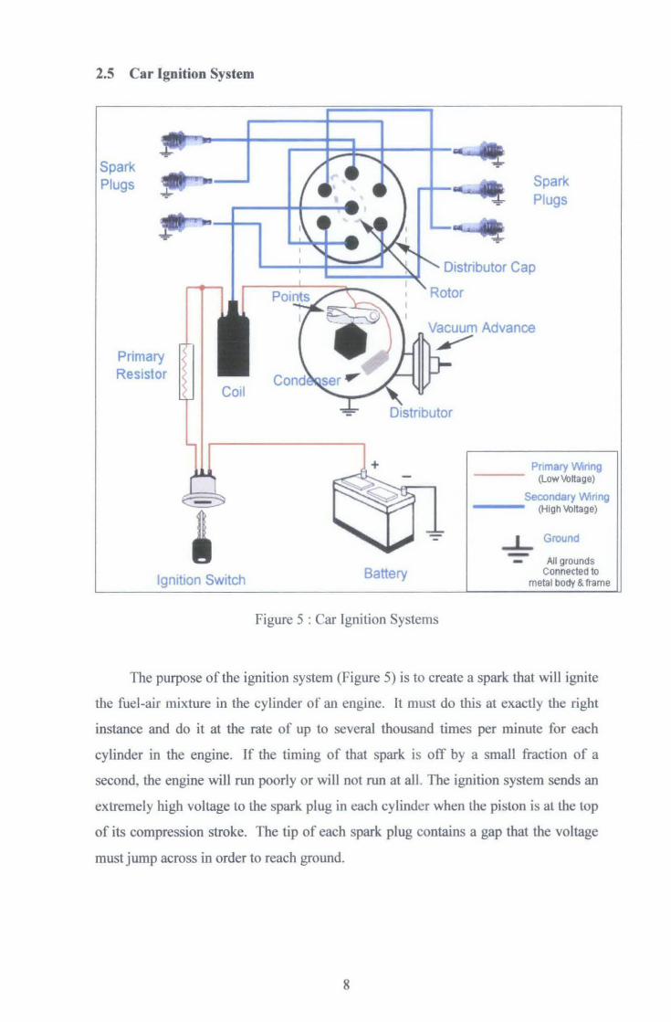
2.5 Car Ignition System
Spark Plugs
Primary Resistor
Ignition Switch
)tor
+
Battery
Figure 5 : Car Ignition Systems
Spark Plugs
Advance
Prtr 'tv • 1 --- (LowVoltage)
Secon~., • VI;, , ''li --- (High Voltage)
...1,_ Ground - All grounds Connected to
metal body & frame
The purpose of the ignition system (Figure 5) is to create a spark that will ignite
the fuel-air mixture in the cylinder of an engine. It must do this at exactly the right
instance and do it at the rate of up to several thousand times per minute for each
cylinder in the engine. If the timing of that spark is off by a small fraction of a
second, the engine will run poorly or will not run at all. The ignition system sends an
extremely high voltage to the spark plug in each cylinder when the piston is at the top
of its compression stroke. The tip of each spark plug contains a gap that the voltage
must jump across in order to reach ground.
8

That is where the spark occurs. The voltage that is available to the spark plug
IS somewhere between 20,000 volts and 50,000 volts or higher. The job of the
ignition system is to produce that high voltage from a 12 volt source and send it to
each cylinder in a specific order, at exactly the right time [5].
2. 5.1 Battery
The automotive battery, well known as lead-acid storage battery, is an
electrochemical device that produces voltage and delivers current. An automotive
battery can works in reverse electrochemical action, thereby recharging the battery,
which will then give us many years of services. The purpose of the battery is to
supply current to the starter motor, provide current to the ignition system while
cranking, to supply additional current when the demand is higher than the alternator
can supply and to act as electrical reservoir.
2.5.2 Ignition Switch
The ignition switch allows the driver to distribute electrical current to where it
is needed. There are generally five-key switch positions that are used :
../ LOCK - All circuits are open (no current supplied) and the steering wheel is
the lock position. In some cars,
../ OFF - All circuits are open, but the steering wheel can be turned and the key
cannot extracted .
../ RUN- All circuits, except the starter circuit, are closed and current is allowed
to pass through. Current is supplied to all but the starter circuit.
../ START- Power is supplied to the ignition circuit and the starter motor only.
That is why radio stops playing if the key in START mode. This position of
the ignition switch is spring loaded so the starter is not engaged while the
engine is running. This position is used momentarily, just to active the starter.
9
.; ACCESSORY - Power is supplied to all but the ignition and starter circuit.
This allows you to play the radio, work the power windows and some other
thing while the engine is not running. Most ignition switches are mounted on
the steering column. Some switches are actually two separate parts :
The LOCK into which you insert the key. This component also
contains the mechanism to lock the steering wheel and shifter.
The SWITCH which contains the actual electrical circuits It is usually
mounted on the top of the steering column just behind the dash and is
connected to the Jock by a linkage or rod.
2.5.3 Neutral Safety Switch
This switch opens and denies current to flow through the starter circuit when
the transmission is in any gear but Neutral or Park on automatic transmission. This
switch is normally connected to the transmission linkage or directly on the
transmission. Most cars utilize this same switch to apply current to the back up light
when the transmission is put in reverse. Standard transmission cars will connect this
switch to the clutch pedal so that the starter will not engage unless the clutch pedal is
depressed.
2.5.4 Starter Motor
The starter motor is a powerful electric motor, with the small gear attached to
the end. When activated, the gear is meshed with the larger gear, which attached to
the engine. The starter motor then spins the engine over so that the piston can draw in
a fuel and air mixture, which is then ignited to start the engine. When the engine starts
to spin faster than the starter, a device called an overrunning clutch automatically
disengages the starter gear from the engine gear.
10
2.6 NPN Type Transistor as a Switch
NPN Type Transistor is the proposed switch for further implementation of the
project. NPN Type Transistor can be operated in two conditions, which is Cut-off
condition for open circuits switch function and Saturation condition as close circuit
switch function.
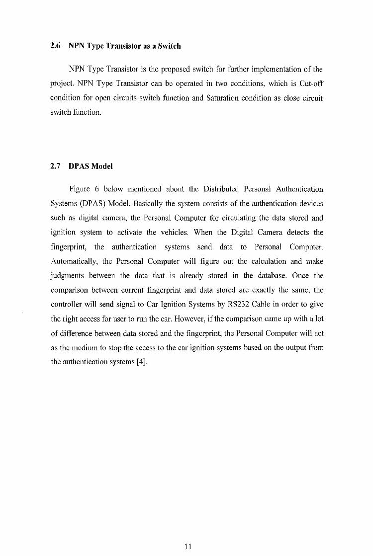
2.7 DPAS Model
Figure 6 below mentioned about the Distributed Personal Authentication
Systems (DP AS) Model. Basically the system consists of the authentication devices
such as digital camera, the Personal Computer for circulating the data stored and
ignition system to activate the vehicles. When the Digital Camera detects the
fingerprint, the authentication systems send data to Personal Computer.
Automatically, the Personal Computer will figure out the calculation and make
judgments between the data that is already stored in the database. Once the
comparison between current fingerprint and data stored are exactly the same, the
controller will send signal to Car Ignition Systems by RS232 Cable in order to give
the right access for user to run the car. However, if the comparison came up with a lot
of difference between data stored and the fingerprint, the Personal Computer will act
as the medium to stop the access to the car ignition systems based on the output from
the authentication systems [ 4].
JJ
Digital
Camera
RS 232 Personal
Computer
Pigure 6 : DPAS Model
12
CHAPTER3
METHODOLOGY
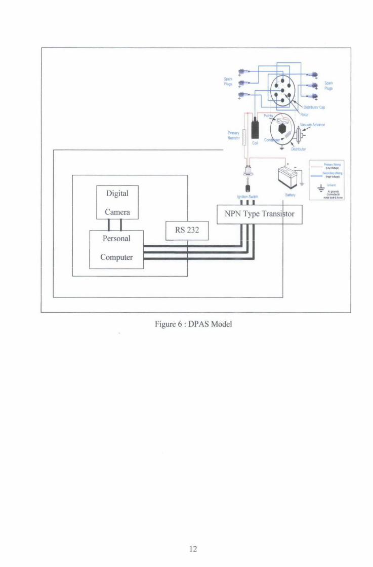
3.1 Sequence of Methodology
The flow of the project methodology is shown Figure 7. The methodology of
the whole project is divided into two phases which are Stage 1 and Stage 2. Below is
the overview of the project methodology.
No
No
No
Start
Research and analysis
Design Concept
Building the Prototype
Product Enhancement
Finish
Figure 7 : Sequence of Methodology
13
Stage 1
Stage 2
3.1.1 Stage I
The project started by defining project titles and scope. Then the schedule is
planned into two stages. For the first stage, literature review of the DPAS was carried
out for the first three weeks. Then, it continued with design concept and several
theoretical aspects that could be needed to achieve a satisfying product towards the
end. Determination of crucial components availability such as used digital camera,
RS 232 communication cables, personal computer, MATLAB software, and car
starter (further research and development) need to be done in the first stage of the
project cycle.
Within the first stage, the aims are to complete the design concept and collect
all necessary equipment within limited budget of RM500.
3.1.2 Stage 2
For the second stage of the projer-t, it was planned that this prototype will be
enhanced with intelligent function with the use of digital camera and personal
computer.
At this stage, all the troubleshooting need to be done correctly as it may affect
the performance of the prototype. Then the prototype will be finalized and be tested
to perform its capabilities. Most of the work load for second stage is with MATLAB
Coding. There are some procedures need to be repeated tremendously in order to
satisfy the project overall requirement. The test area for this purpose was initially
planned in the lab since there is still in research development stage and further studies
need to be done in order to implement it to real vehicle.
14
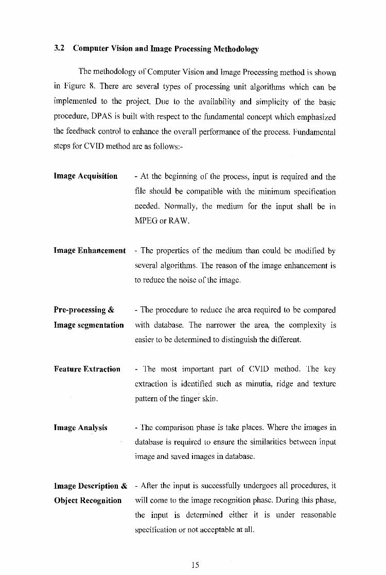
3.2 Computer Vision and Image Processing Methodology
The methodology of Computer Vision and Image Processing method is shown
in Figure 8. There are several types of processing unit algorithms which can be
implemented to the project. Due to the availability and simplicity of the basic
procedure, DP AS is built with respect to the fundamental concept which emphasized
the feedback control to enhance the overall performance of the process. Fundamental
steps for CVID method are as follows:-
Image Acquisition - At the beginning of the process, input is required and the
file should be compatible with the minimum specification
needed. Normally, the medium for the input shall be in
MPEGorRAW.
Image Enhancement - The properties of the medium than could be modified by
several algorithms. The reason of the image enhancement is
to reduce the noise of the image.
Pre-processing & - The procedure to reduce the area required to be compared
Image segmentation with database. The narrower the area, the complexity IS
easier to be determined to distinguish the different.
Feature Extraction
Image Analysis
- The most important part of CVID method. The key
extraction is identified such as minutia, ridge and texture
pattern of the finger skin.
- The comparison phase is take places. Where the images in
database is required to ensure the similarities between input
image and saved images in database.
Image Description & - After the input is successfully undergoes all procedures, it
Object Recognition will come to the image recognition phase. During this phase,
the input is determined either it is under reasonable
specification or not acceptable at all.
15
INPUT IMAGE
Image
Acquisition
Object
Recognition
OBJECT
Image
Enhancement
Image
Description
Pre
Proce sing
Knowledge Base
Image
Analysis
Figure 8 : CVID Technique
3.2.1 Fingerprint Image Processing using CVID Methods
Image
Segmentation
Feature
Extraction
Fingerprint Image enhancement is to make the image clearer to boost further
operations. Since the fingerprint images acquired from sensors or other medium are
not assured with perfect quality, those enhancement methods, for increasing the
contrast between ridges and furrows and for connecting the false broken points of
ridges due to insufficient amount of ink, are very useful for keep a higher accuracy to
fingerprint recognition. There are several alternatives that are able to enhance the
quality of the raw picture. Throughout the project, the method that is adopted in the
project is Histogram Equalization.
16
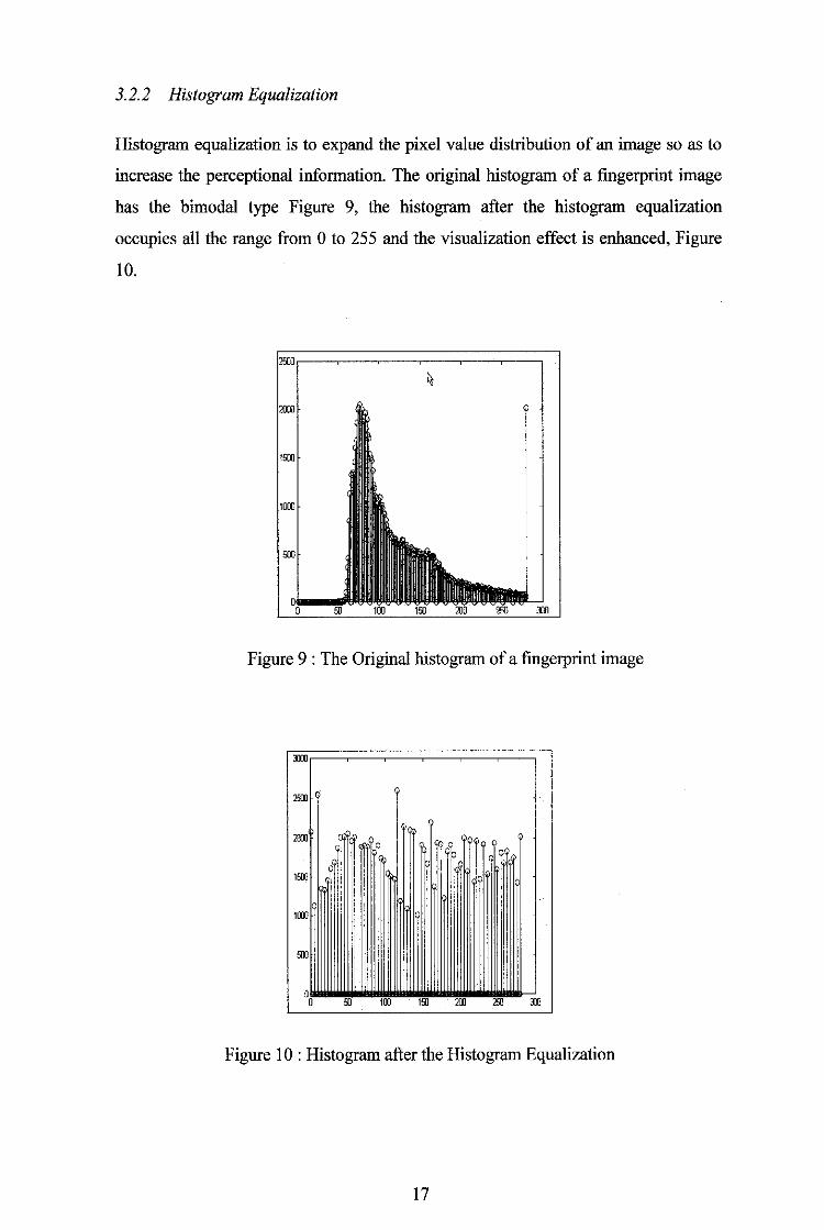
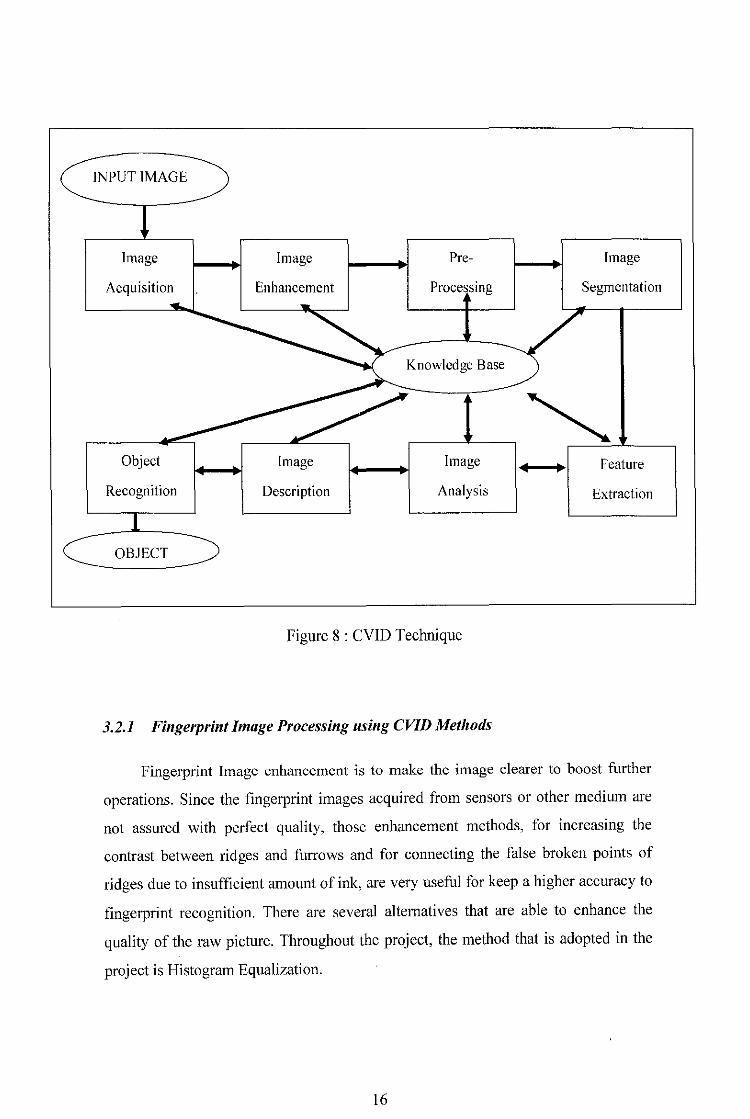
3.2.2 Histogram Equalization
Histogram equalization is to expand the pixel value distribution of an image so as to
increase the perceptional information. The original histogram of a fingerprint image
has the bimodal type Figure 9, the histogram after the histogram equalization
occupies all the range from 0 to 255 and the visualization effect is enhanced, Figure
10.
Figure 9 : The Original histogram of a fingerprint image
Dll
25lll
2001 li>. QQ,
'"" '""
"" 0 0 !ll 100 1!ll 2[jJ 2!ll 3JO
Figure I 0 : Histogram after the Histogram Equalization
17
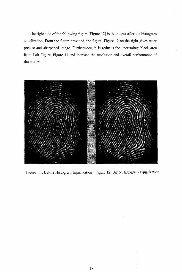
The right side of the following figure [Figure 12] is the output after the histogram
equalization. From the figure provided, the figure, Figure 12 on the right gives more
precise and sharpened image. Furthermore, it is reduces the uncertainty black area
from Left Figure, Figure II and increase the resolution and overall performance of
the picture.
Figure II : Before Histogram Equalization Figure 12 : After Histogram Equalization
18

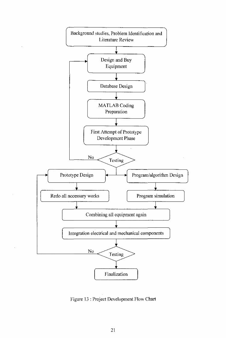
3.3 Project Development
Referring to Figure 13, it can be seen that the first stage of project development
IS researching on background studies, problem identification and also literature
review. With all information needed in hand, the mechanical structure was designed
according to the localized material available in the market. Fortunately, I am using
UTP lab computer and my own Personal Computer, so it reduces the cost of about
one thousand Ringgit Malaysia.
When all the structure is finalized and tested, the circuit and the algorithm of
the controller are designed. The program algorithm was designed using MATLAB
compiler using C language. Then the finished program is tested using a simulated
software called Simulator/Simulink to simulated the effect of the program to the
desired controller's I/0 system. After that, the program is compiled into database files
and uploaded (flash) into the MATLAB Works. Next, the digital camera is connected
to PC and functionality test been conducted and several programs timing to the real
application also been calibrated. If the functionality of the algorithm is not as desired,
the process of reprogram the algorithm need to taken. This process is repeated until
the program and smooth functioning accordingly.
20
Background studies, Problem Identification and Literature Review
~ Design and Buy
Equipment
~ Database Design
~ MA TLAB Coding
Preparation
+ First Attempt of Prototype
Development Phase
No Testing
-- Prototype Design Program/algorithm Design
+ + Redo all necessary works I Program simulation
i i Combining all equipment again
+ Integration electrical and mechanical components
No Testing
Finalization
Figure 13 : Project Development Flow Chart
21
4.1 FINDINGS
CHAPTER4
RESULT AND DISCUSSION
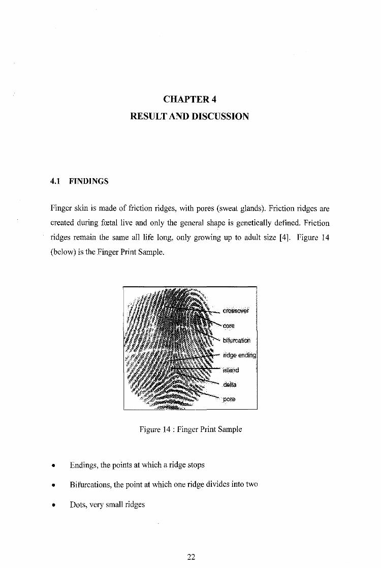
Finger skin is made of friction ridges, with pores (sweat glands). Friction ridges are
created during fmtal live and only the general shape is genetically defined. Friction
ridges remain the same all life long, only growing up to adult size [4]. Figure 14
(below) is the Finger Print Sample.
crossover
ridge
island
delta
Figure 14 : Finger Print Sample
• Endings, the points at which a ridge stops
• Bifurcations, the point at which one ridge divides into two
• Dots, very small ridges
22
• Islands, ridges slightly longer than dots, occupying a
middle space between two temporarily divergent ridges
• Ponds or lakes, empty spaces between two temporarily divergent ridges
• Spurs, a notch protruding from a ridge
• Bridges, small ridges joining two longer adjacent ridges
• Crossovers, two ridges which cross each other
• The core is the inner point, normally in the middle of the print, around which
swirls, loops, or arches center. It is frequently characterized by a ridge ending
and several acutely curved ridges.
• Deltas are the points, normally at the lower left and right hand of the fingerprint,
around which a triangular series of ridges center.
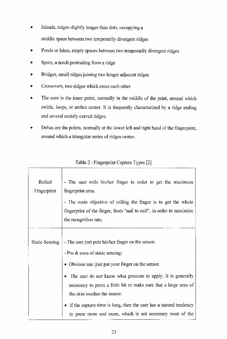
Rolled
Fingerprint
Table 2 : Fingerprint Capture Types [2)
- The user rolls his/her finger m order to get the max1mum
fingerprint area.
- The main objective of rolling the finger is to get the whole
fingerprint of the finger, from "nail to nail", in order to maximize
the recognition rate.
Static Sensing - The user just puts his/her finger on the sensor.
- Pro & cons of static sensing:
• Obvious use: just put your finger on the sensor.
• The user do not know what pressure to apply. It is generally
necessary to press a little bit to make sure that a large area of
the skin touches the sensor.
• If the capture time is long, then the user has a natural tendency
to press more and more, which is not necessary most of the
23

Sweeping
Reading
time, but may break the sensor in worst cases.
• If the user apply at the same time a rotation (which is never
recommended), the skin plasticity makes a distorted image.
• After a while, the sensor becomes dirty (especially on the edge)
which may be a problem for the acquisition, and users may
become reluctant to use it.
The user sweeps his/her finger on the sensor.
• This is not a natural way of acquisition, user has to learn how
to use it.
• The reader is always clean: each swipe cleans the sensor.
• No latent print on the sensor.
• No feeling of "leaving" his/her fingerprint: the swipe is short
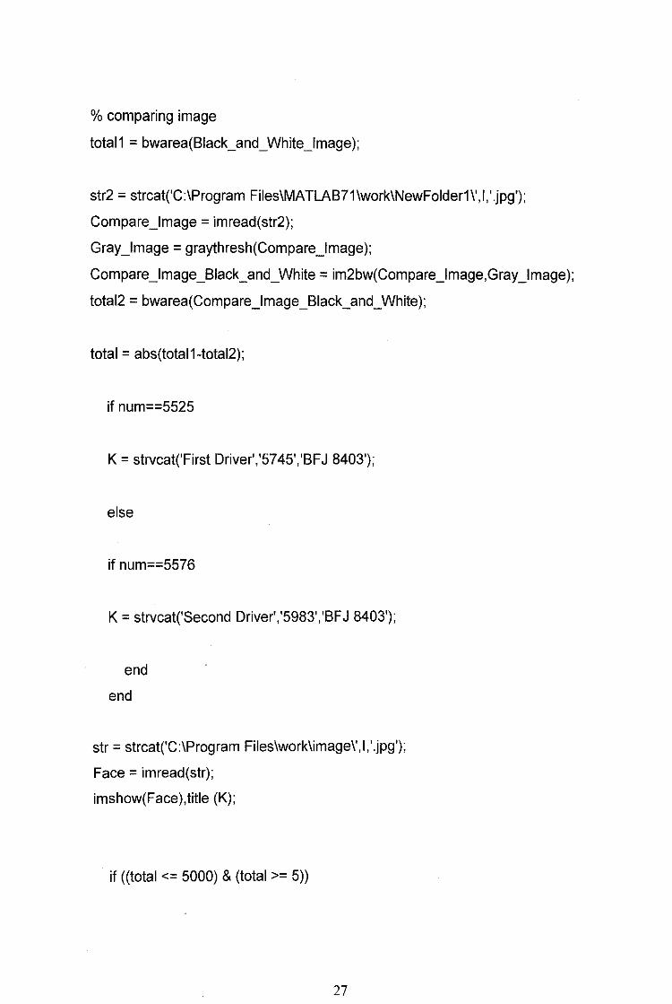
4.2 MATLAB Coding
This part includes some information regarding to the MATLAB coding for
authentication systems. The program is able to execute and compare between stored
data base with a new one and find the similarities between them. So only authorized
consumer may have the access to enter the ignition system for the vehicle. Below is
the MATLAB Coding for DPAS throughout the project. Modification and adjustment
to the system are based on this MATLAB Coding.
24

THE PROGRAM
clear all
close all
clc
%maximum number of student's ID
M=5000· ,
l=input('Piease enter your Driver's ID: \n', 's');
num = str2num(l);
if ((num <= 7000) & (num >= 5000))
%targets the filename of the database image
str = strcat('C:\Program Files\MATLAB71\work\trial1\',l,'.jpg');
New_lmage = imread(str);
imshow(New_lmage),title (['Original Image']);
[irow icol pin]= size(New_lmage);
%resize image to 320x243
Resized_lmage = imresize(New_lmage,[243 320]);
New_lmage = Resized_lmage;
imwrite(New_lmage,str);
%cropping the image
Crop_lmage = imcrop(New_lmage,[60 60 200 180]);
Resized_Crop_lmage = imresize(Crop_lmage,[243 287]);
Crop_lmage = Resized_Crop_lmage;
figure,imshow(Crop_lmage),title (['Cropped image']);
25

%convert image to black and white if image is colour image(RGB)
if pln>1
%image preprocess
Gray_lmage = rgb2gray(Crop_lmage);
figure,imshow(Gray_lmage),title (['Gray image']);
Equalized_lmage = adapthisteq(Gray_lmage);
figure, ill]hist(Equalized_lmage),title (['Histogram of the image']);
figure,imshow(Equalized_lmage),title (['After histogram equalization image']);
Filter_lmage = medfilt2(Equalized_lmage, [3 3]);
figure,imshow(Filter_lmage),title (['Median filtered image']);
Graythresh_lmage = graythresh(Filter_lmage);
Black_and_White_lmage = im2bw(Filter_lmage,Graythresh_lmage);
figure,imshow(Biack_and_White_lmage),title (['Black and White image']);
else
%image preprocess
Equalized_lmage = adapthisteq(Gray_lmage);
figure, imhist(Equalized_lmage),title (['Histogram of the images']);
Filter_lmage = medfilt2(Equalized_lmage, [3 3]);
figure,imshow(Filter_lmage),title (['Median filtered image']);
Graythresh_lmage =graythresh(Filter_lmage);
Black_and_White_lmage = im2bw(Filter_lmage,Graythresh_lmage);
figure,imshow(Biack_and_White_lmage),title (['Black and White image']);
end
26
% comparing image
total1 = bwarea(Biack_and_White_lmage);
str2 = strcat('C:\Program Files\MATLAB71\work\NewFolder1\',l,'.jpg');
Compare_lmage = imread(str2);
Gray_lmage = graythresh(Compare_lmage);
Compare_lmage_Biack_and_White = im2bw(Compare_lmage,Gray_lmage);
total2 = bwarea(Compare_lmage_Biack_and_White);
total = abs(total1-total2);
if num==5525
K = strvcat('First Driver','5745','BFJ 8403');
else
if num==5576
K = strvcat('Second Driver','5983','BFJ 8403');
end
end
str = strcat('C:\Program Files\work\image\',l,'.jpg');
Face = imread(str);
imshow(Face),title (K);
if ((total <= 5000) & (total >= 5))
27

disp('Engine Activated','Remain Calm and Place Your Seal Belt. Thank you.')
else
disp ('ACCESS DENIED!!! Please Try Again.')
end
else
disp('SORRY, YOU ARE NOT AN AUTHORIZED DRIVER');
end
28
4.3 Result
Below is the coding design and brief description for each part for the whole process.
This would be the actual MATLAB Coding for the whole implementation process.
--------------------------------------------------------------------------------------------------Database
l=input('Piease enter your student ID:\n','s');
num=str2num(l);
if((num<=7000)&(num>=5000)
str=strcat('C:\Program Files\work\trial1 \',I', .jpg');
Newlmg=imread( str);
imshow(Newlmg),title(['Origanal Database']);
=================================================
The command above is to create a database in order to store details for each input
image. In this case, the information for each fingerprint will be stored and called-out
from the MATLAB file itself. The reason behind the design is to ensure the
MA TLAB is able to compare essential information whenever needed. The
authentication of the whole system also starts with the database that is pre-installed in
the systems.
--------------------------------------------------------------------------------------------------
l=imread('New.jpg');
figure,imshow(l);
title('Mohd Shahadan');
imtool(l);
=================================================
29
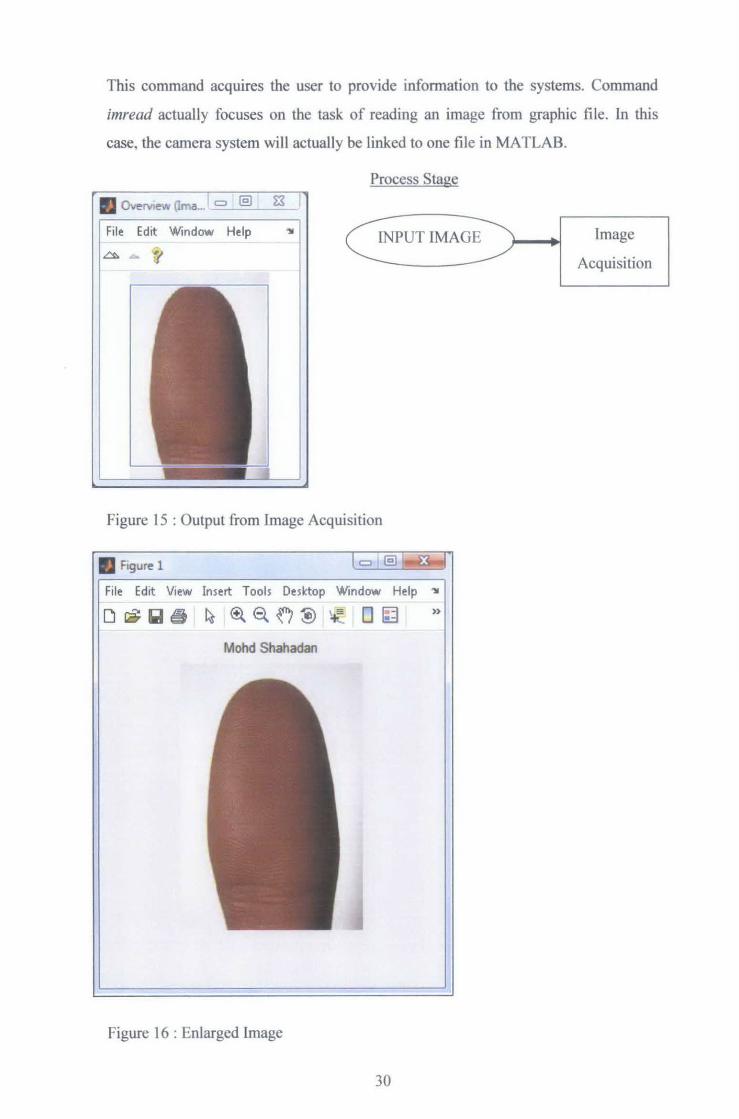
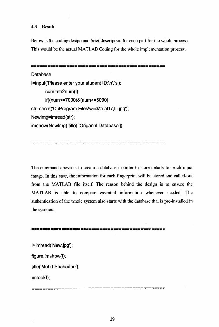
This command acquires the user to provide information to the systems. Command
imread actually focuses on the task of reading an image from graphic file. In this
case, the camera system will actually be linked to one file in MA TLAB.
Process Stage
File Edit Window Help
Tl
Figure 15 : Output from Image Acquisition
• Figure 1
File Edit View Insert Tools Desktop Window Help '11
»
Mohd Shahadan
Figure 16 : Enlarged Image
30
Image
Acquisition
• Image Information Omage T ooll) l. c::::J @) ~ I
"ii
Image details (Image Tool1 - I) -I Attribute Value
11 Wdth(columns 182 ~
~ Height ~rows) 261 - -3 Class uint8 -~ Image type truecolor
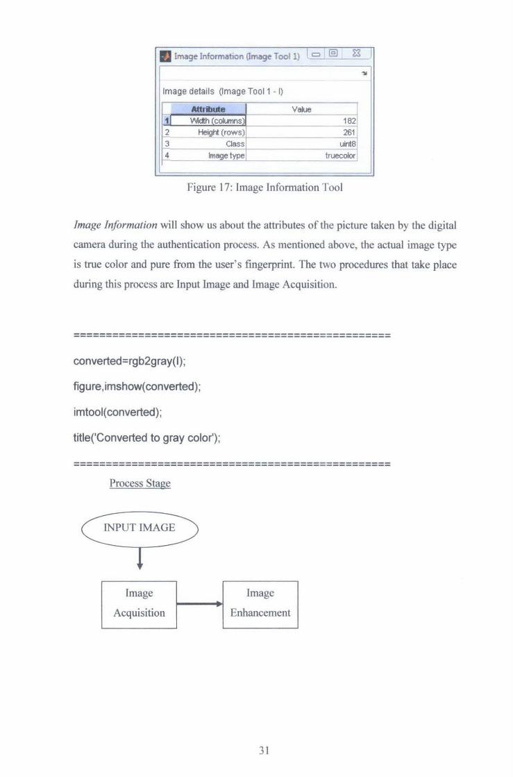
- -Figure 17: Image Information Tool
Image Information will show us about the attributes of the picture taken by the digital
camera during the authentication process. As mentioned above, the actual image type
is true color and pure from the user's fingerprint. The two procedures that take place
during this process arc Input Image and Image Acquisition.
--------------------------------------------------------------------------------------------------converted=rgb2gray(l) ;
figure,imshow(converted);
imtool( converted);
title('Converted to gray color');
--------------------------------------------------------------------------------------------------Process Stage
Image Image
Acquisition Enhancement
31
Output
II Figure 2 ----., File Edit View Insert Tools Desktop Window Help "~
D~liil®i ~ ~e.o~ ~: o~
Converted to gray color
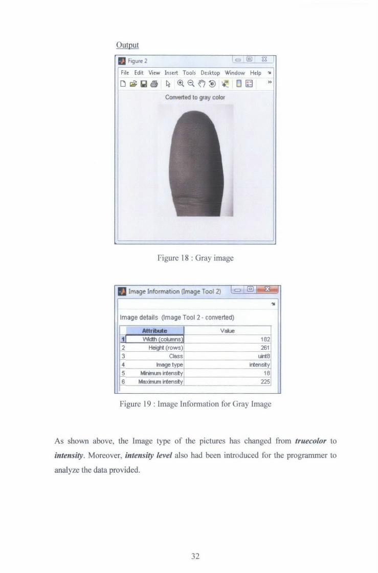
Figure 18 : Gray image
• Image lnformatton (Image Tool 2) I C) I @l
Image details Omage Tool 2- converted)
r--;- -Attribut- . - e- l __ Value
1J \Aildth (columns )I 2 Height (rows)
r1 Class
4 lmagetype
ri Minimum intensity
J1 Maximum intensity
182,
261 uinta
intensity
18
225
Figure 19 : Image Information for Gray Image
As shown above, the Image type of the pictures has changed from truecolor to
inte11sity. Moreover, intensity level also had been introduced for the programmer to
analyze the data provided.
32
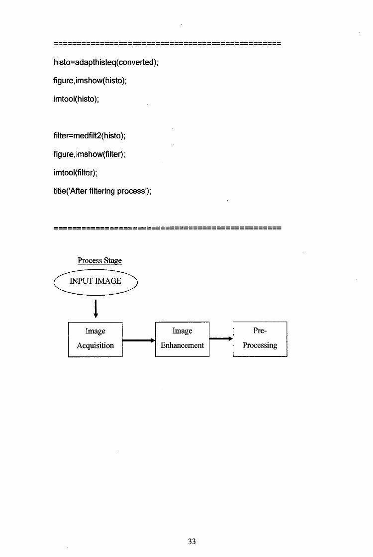
================================================= histo=adapthisteq( converted);
figure,imshow(histo);
imtool(histo);
filter=medfilt2(histo);
figure,imshow(filter);
imtool(filter);
title('After filtering process');
--------------------------------------------------------------------------------------------------
Process Stage
INPUT IMAGE
l Image Image Pre-
Acquisition Enhancement Processing
33
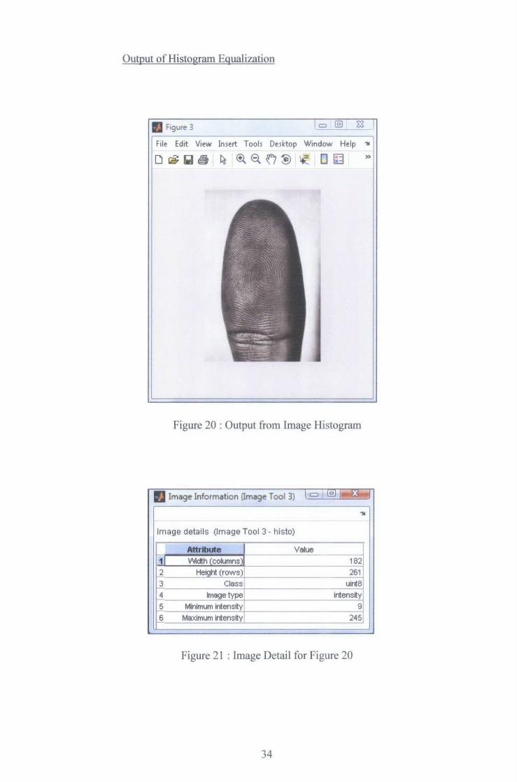
Output of Histogram Equalization
• ~igur~ 3 ., File Edit View Inmt Tools Desktop Window Help ~
D IS liil ~ ~ ®. Et f7 ~ 'lt-: 0 63
Figure 20 : Output from Image Histogram
II Image Information (Image Tool 3) [ c::::J I ~ ~:4..1
~
Image details (Image Tool 3- histo)
L Attribute Value -- -1J Width (columns) 182
b Height (rows) 261 -3 Class uinta
[ 4 -
Image type intensity 5 Minimum intensity 9 -- ~ --ts Maximum intensity 245
Figure 21 : Image Detail for Figure 20
34
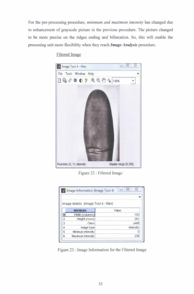
For the pre-processing procedure, minimum and maximum intensity has changed due
to enhancement of grayscale picture in the previous procedure. The picture changed
to be more precise on the ridges ending and bifurcation. So, this will enable the
processing unit more flexibility when they reach Image Analysis procedure.
Filtered Image
IJ lmage Tool4- filter
File Tools Window Help ~
l [g[;}s~ 0 . ()1 ~6.0~ 1 100% o:J
Pixel info: (X, Y) ..-.ensity Display range: (0 255]
Figure 22 : Filtered Image
. Image Information 11mage Tool 4) l = @) 1 ~ I
~ I Image details (Image Tool 4- filter)
~ Attrlde ~ Value
Weith ~columns: 182 Height (rows) 261
~ Class uint8 Image tyPe intensity
[5 Minimum intensity 0
Ji Maximum intensity 239
Figure 23 : Image Information for the Filtered Image
35
The filtering process removes the noise to further enhance the ridges ending and
bifurcation of fingerprint. This actually gives a more presentable data for the
MATLAB to differentiate between data that are pre-installed with the data prompt
during authentication activity.
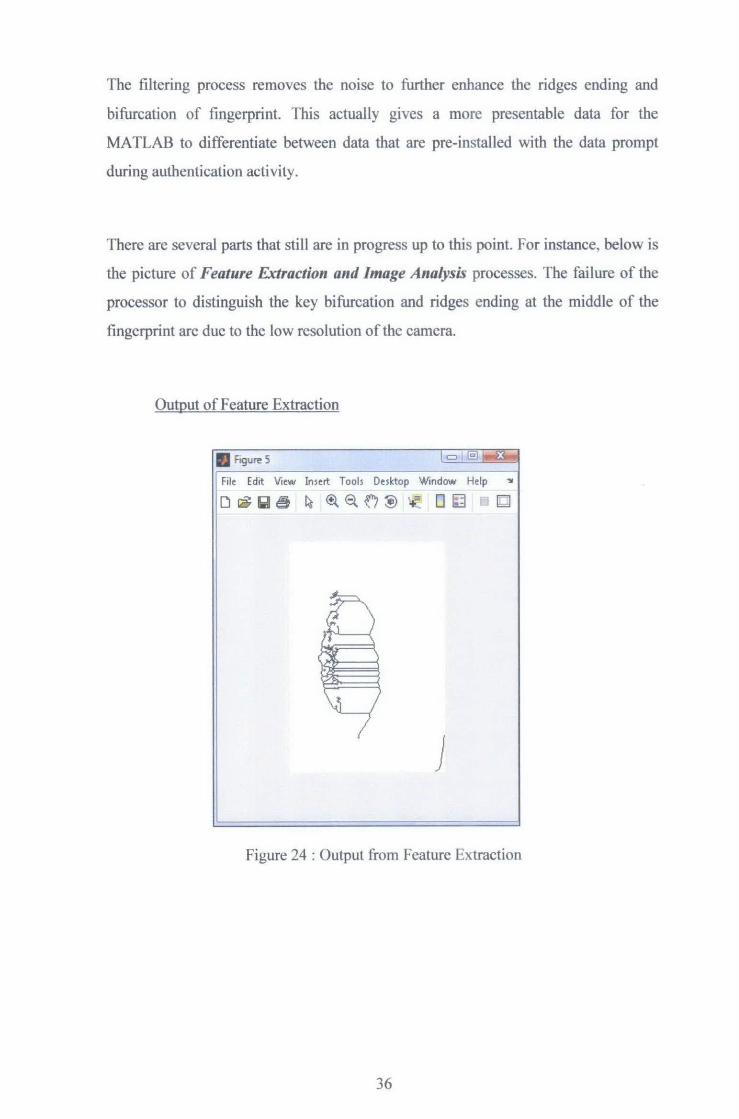
There are several parts that still are in progress up to this point. For instance, below is
the picture of Feature Extraction and Image Analysis processes. The failure of the
processor to distinguish the key bifurcation and ridges ending at the middle of the
fingerprint arc due to the low resolution of the camera.
Output of Feature Extraction
• Figure 5
File Edit Vi~ Insert Tools Desktop Window Help '11
D ~lll€t ~ ~~~~ ~ 0~ 0
J
Figure 24: Output from Feature Extraction
36
4.4 Discussion
There are several components that should be taken care throughout the project.
The main objective is to develop a simple project prototype which is able to simulate
and run fingerprint authentication system. Moreover, the study of integration of car
ignition systems also needs to be done as a pre requirement of the overall project.
Unfortunately, the cost constraint and time limitation would be hassle along the
project cycle. The end result from the MATLAB Coding seems not encouraging due
to the parameter given from used digital camera. The output did not precisely show
the fingerprint layer and only concentrated at the left side of the picture (Figure24).
The expected result of the real simulation and testing is the successful fingerprint
layer that is compared with database and reflected from the raw picture of digital
camera Then in the other hand, the succeed result will send a signal to car ignition
systems by RS232 communication cable. Furthermore, MATLAB coding that is
implemented in the project also can be improved by some modification of the
algorithms. The used digital camera gives about four-mega pixel output compared
with actual fingerprint scanner which is using advanced optical devices provided with
heat detbctor. So the end result can be improved by using high end optical devices
and modification of MA TLAB coding.
37

CHAPTERS
CONCLUSION AND RECOMMENDATION
5.1 Conclusion
Personal Authentication Systems plays a vital role in enhancing the security
systems in human life. Due to that matter, the advanced systems need to be invented
in order to increase the reliability of the technology and maintain the effectiveness of
the systems. Research of the current systems will enable us to determine the best
solution to boost the technology into maximum capacity. Besides that, the application
of the systems also might be wider since human are able to explore new approaches
for design and integration of the systems into some other complex technologies. The
critical parameters to be looked into are the architecture of the authentication systems,
devices, peripheral and the overall application of output systems. Further progress of
the project would be the enhancement of the output quality and MA TLAB
modification before the final presentation.
5.2 Recommendation
The fingerprint authentication systems could be improved by some methods.
One of the main considerations for improvement is the usage of Digital Camera
which equipped with higher pixel capability to increase accuracy and precision of
consumer's fmgers. Moreover, the Matlab coding also can have a huge boost by some
modification in the Computer Vision and Image Processing Techniques. Other than
that the communications interface for human and Personal Computer also can be
increased its capability by adding some buttons for user-friendly and increased
accuracy.
38

For a recommendation, more research and upgraded techniques is needed to
ensure their reliability as well as maintenance-friendly. Furthermore, the second part
of the project which includes the integration of Car Ignition Systems is not well
established for prototype, so hopefully some other students will continue this project
in some other time. For future planning, there should be another back-up system if
failure occurs during the start up process.
39
REFERENCES
[1] S. Nanavati, M. Thieme, R. Nanavati, 2002,
Biometrics Identity Verification In A Networked World, New York,
Jolm Wiley & Sons.
[2] http://www.biometrics.tibs.org/
[3] Bolle, Connell, Pankanti, Rathe, Senior, 2004
Guide To Biometrics, New York,
Springer-Verlag.
[ 4] The International Biometric Society,
1444 I Street, NW, Suite 700
Washington, DC 20005, USA
[5] http://www.familycar.com/Classroom/ignition.htm
[ 6] http:/ I perso .orange. fr/fingerchi p/biometrics/types/fingemrint algo.htm
[7] http://secureaction.com
[8] http://csoftlab.com
[9] http://perso.orange.fr/fingerchip/biometrics/tvpes/fingemrint algo.htm
40

APPENDICES
41

APPENDIX A
GANNTCHART
42

FINAL YEAR DESIGN PROJECT SCHEDULE
2007/2008 TASK JULY I AUG SEP OCT NOV DEC JAN FEB MAC APR MAY JUN
11 2 3 41 11 21 3 4 1 2 3 4 1 2 3 4 1 2 3 4 11 2 3 4 1 2 3 4 1 2 3 4 1 2 31 4 1 2 3 4 1 21 3 4 11 2 3 4 FYP1 I I I ! I ' i I I I +---- --i
I ---Title Selection I I i I I ! ~- -"-- --Research Work I i I I -- ' t+·-[= Submission of Preliminary Report : I I I I I Learning Software (MATLAB) Designing Database ' I ! Project Work I T l-
--~-----~-
Seminar 1 I I I I I I I t-- - ~t =-t-I
Seminar 2 I I!~
I i I I I -- --1-+ -
Submission of Interim Report i ' I I I Oral Presentation I I I i I I I I ---l I I ·--~---~ -
I i I I I r I - ~--·---
I I i '
FYP 2 ' I I i i I I - ------- 1-_l __ --+# ·--- ! Continuation from FYP 1 I I I I ! --- ----~ --r --- I _L --I I I I I _I __
Project work continue I mil I I I f
- i Evaluation I I I I I L _l Seminar ' I I I I ' ----
' ' I
Poster Exhibition I I I ·- I I I I I Final draft report I I I I I I --=ra~ -- --JI!IIr~ M+++ ~ ' Oral Presentation ! I I J I I
Hardbound Dissertation I '
I I ! I i I --r r·· -
I ' I i i I I I I I I ' ' I I I I I ! 1 '
' ' I I i I i - ~ ~ j I _:_ 1 1 - - ~ I rr I I I I
' I I - I : ; . i f--I-F1--! -T I I T -;:_:_:_~-- --I -. r-I
' I I I ! I '
! I ' I I I I I -l 1 ' _ ___ i r-=-~-=~- -r ---I ! I I !
I I I - i 1--'--"- I --I I i I I I
I r -: ' : - -±=t-=f-~-I I I i I ! ___ -~ - T-- _ _::c_ _ f i i I I I
' I I I I I I I I I I - r---! I ' - i -l I ---! '
I I I I .L . . I ~-I ~I I I -- i i I I i I I T I I I- I i I '
i I ' I I I I T--1---T . ~---- ---+- I I . -
' --r-- -- . ·- T I --~-~ --I ! ' ! _ _l_j__[__ ' I I I I ' L I j_ I I ! I I I I I i I-I
I I I I I I ! I - I ' I I I - - i i I I -+-

APPENDIXB
CAMERA SPECIFICATION
43

12 Appendix
Camera Specifications
Kodak EasySbare DX~O ZOOIIl !llgital caine"! .· •.
Cotor u.-oit, millions or rotors
Color modes Color, black & white, sepia
Communication with computer USB, via: USB cable; EasyShare camera dock 6ooo; or printer dock 6000
Dimensions Widlh 4.3 in. (109 mm) Depdt 1.5 in. (38 mm) Height 2.5 in. (64.5 mm)
Weight 7.8 oz (220 g) wilh battery and card
Exposure metering Multi·pattern/Ceoterweighted, center spot m-AE with program modes
Hie format Still jPEG/EXIF v2.2 _ ....
&ii/Wlll Video QuickTime
Audio G.7Il
Flash Modes Auto, Fill, Red-eye, OIJ
Range Wide: 1.6-16.7 ft (0.5-5.1 m) f/2.4 Tele: 2.5-8.5 ft (0. 75-2.6 m) f/4.8
Charging Time Less than 9.0 seconds wilh charged battery
Focus zone Multi-zone, center zone
Image 112.5 in. interline transferCCD, 4:3 aspect ratio, RGB BayerCFA, sensor 4.23 M pixels (2408 X 1758 pixels)
103
Chapter 12
• Kodak EasySbareDX6440 ~-jtigiW camera .
Power Battery. CRV3, (included!, 2-~ li!"\mn, 2-AA Ni-MH, Ni-MH rechargeable battery pack (included with camera dock 6000 and pritUer dock 6oOO)
AC adapter: 3V DC (purchase separately)
Self1'imer 10 seconds
Tripod socket Yes
Video Out NTSC or PAL selectable
Video resolution 320 x 240 pixels, 15 fps
Viewfinder Optical, with diopter adjustment
White balance Auto, Dayligh~ Tungsten, fluorescent
Zoom (still capture) 4X optical, 3.8X digital
Shu"t;ter Speeds For shutter speeds slower lhan 1/30 second, place the camera on a flat, steady surface or use a tripod
Picture. '~)~king Mode Available Shouer Speeds
Auto, Portrait, Wine: 1/2200-1/bO sec., Tele: 1/2200--1/125 sec. Landscape*, Close-up, Wide: J/2200-118 sec., Tele: 1/2200-118 sec. PAS-Program and (Flash: Of!) Aperture priority modes *Long Time Exposure: 4 sec. max. (Landscape only)
Nigbt 112200 to 112 sec.
Sport Wide: 112200 to 1/60sec., Tele: 112200 to 11125 sec. Wide: 1/2200 to 1130 sec., Te1e: 1n200 to 1/60 sec. (Flash: Oil)
PAS-Shutter priority 1n200 to 4 sec.
105
Chapter 12 • Kodak 1!asJ8hiu'< UX6440 ZO!llll. !llgital,<allleta ISO speea Automatic 100 to 200
Manual 100, 200, or 400 Long time exposure 100 Flash 120 or 180 (Automatic)
Video 100 to 800
Lens Tjpe Optical quality glass., 6 groups/7 elements (2 asphericallenses)
Aperture Wide: f/2.2 - f/5.6; Tele: f/4.8 - f/13
Focal Length 33- 132mm
Focus Distance StandandWide: 19.7in. (50 em) to infinity Standand Tele: 29.5 in. (75 em) to infinity Close-up Wide: 3.9 to 23.6 in. (10 em to 6ocm) Close-up Tele: 9.8 to 33.5 in. (25 em to 85cm) Landscape: Fixed focus
liquid Cryst.J Display, LCD l.Sin. (45.7 mm), color, 560 x 240 (camera screen) ( 134k) pixels. Preview rate: 24 fps
Operating Temperature 32to104 F(Oto40 C)
Picture/Video storage 16MB internal; optional SD Card or MMC
Pixel Best*** 2304x 1728 (4.0 M) pixels resolution Best (3:2) *** 2304 X 1536 (3.5 M) pixels
Better** I656x 1242 (2.1 M) pixels
Good* 1200x 900 (Ll M) pixels
104
Chapter 12 • Original Factory Settings
Feature Factory Setting
Aav. Digitat Zoom initiation Pause
Color Mode Color
Date!fime 2003/01/01; 12:00
Date/fime Stamp Off
Defauh Print Quantity I
Exposure Compensation 0.0
Exposure Metering Mode Multi-pattern
Flash Auto, Sport, Portrait, Nigh~ PAS: Auto Landscape, Close-up, Video, Burst Off
Focus Zone Multi-zone
Image Storage Auto
ISO Speed Auto
Language English
Liveview Off
Long Time Exposure None
Manual (PAS) mode Program mode (P)
Orientation Sensor On
PAS- Aperture 12.8 PAS- Exposure Compensation 0.0 PAS- Shuner Speed l/6o
Picture Quality Best
Quiclasew On
106