distributed by: national technical information service u ... · national technical information...
TRANSCRIPT

AD-777 186
A STUDY OF ELECTRONICS RADIATION HARDNESS ASSURANCE TECHNIQUES. VOLUME II, PART 2, ELECTRICAL SCREENING FOR IONIZING RADIATION RATE AND TOTAL DOSE EFFECTS
I. Arimura, et al
Boeing Company
Prepa red for:
Air Force Weapons Laboratory
January 1974
DISTRIBUTED BY:
National Technical Information Service U. S. DEPARTMENT OF COMMERCE 5285 Port Royal Road, Springfield Va. 22151
5 *
.
*^SBJ ' ■■ . m

jCKse "■' tjr
KTI3 X -■•» I DIC F. . i' -:t:jfl f]
j utm*;: "2D Ü
i CA 'OK
lir 1 :■■■ * .
?:■ *ii> »MR.« "U irr K3ES
^ AIR FORCE WEAPONS LABORATORY
Air Force Systems Command Kirtland Air Force Base
New Mexico 87117
*l When US Government drawings, specifications, or other data are used for
any purpose other than a definitely related Government procurement operation, the Government thereby incurs no responsibility nor any obligation whatsoever, and the fact that the Government may have formulated, furnished, or In any way supplied the said drawings, specifications, or other data, is not to be regarded by implication or otherwise, as in any manner licensing the holder or any other person or corporation, or conveying any rights or permission to manufacture, use, or sell any patented invention that ay in any way b<» related thereto.
DO NOT RETURN THIS COPY. RETAIN OR DESTROY.
/>-
'SuMtäU« . I
UNCLASSIFIED Srtunty Classification Kb-TillZL
DOCUMENT CONTROL DATA R&D (Security classification of title, body ol abstract and indexing annottt'ivn must be entered when the overall report la classified)
i ORIGINATING ACTivtiy (Corporate author)
The Boeing Company •'Seattle, Washington 98124
Zm. REPORT VC C U «* I T V CLASSIFICATION
UNCLASSIFIED 2b. GROUP
REPORT TtTLE
A STUDY OF ELECTRONICS RADIATION HARDNESS ASSURANCE TECHNIQUES
Volume II, Electrical Screening for Ionizinq Radiation Rate and Total Dose Effects, Part 2
». DESCRIPTIVE NOTES (Type ot report end inclusive dale«;
31 July 1970 through 16 July 1973 5 AUTHORS) ;fj:r«f name, middle initial, teat name)
I. Arimura, et al.
a. REPORT DATE
January 1974 na. CONTRACT oa GRANT NO
F2960 .-71-C-0Ö01 b. PROJt.C T NO
8809, 133B, WDNE r- Task 11, DE, 01 d.
Ja. TOTAL NO OF PACES
3INATOR'S *.EFO^T NUMBER«51
7h HO IF RfFJ
44
AFWL-TR-73-m, Vol. II, Pt 2
96. OTHER REPORT NO^'Sl (Any other number» that may be astlQred this report)
10 DISTHlBUriOU STATEMENT
Approved for public release; distribution unlimited. NATIONAL TECHNICAL INFORMATION SERVICE U S Department of Commerce
Springfield VA 22151
11 SUPPLF.MEM . a P- "OTeS 12 SPONSORINS MILITÄR.' ACT'VFTr
Air Force Weapons Laboratory (ELP) Kirtland Air Force Base, NM 87117
\Distribution Limitation Statement A) ill ABSTRACT
Thii program determined physical failure modes of a range of discrete and inte- grated semiconductor devices exposed to ionizing rate, neutron, and total dose envi- ronments. rrorn physical reasoning possible electrical parameter measurements were determined which had some probability of correlating with the radiation sensitivity and failure thresholcs. It was determined that base transit time normal i^4-ion for nejtrcn degradation was genera'My effective for low-power transistors, but ineffective for power devices. Other AC and a few DC measurements also were found to be effective potential screens for neutron degradation. No particular advantage was noted for using electrical storage time constant s compared to electrical storage time for screening primary photocurrents of low-o^wer discrete devices. In some cases, the integrated circuits were obtained with nonstanda,~d metallization, "special lead," topologies to enable electrical measurements to b2 made at internal circuit nodes. In I'r's Volume (Volume II), the utility of these measurements as correlation parameters K.-s compared to that obtained from measurements made using unmodified circuits. Excellent correlation was obtained between tie neutron degradation of the logic cir- cuits and the emitter-base turn-on voltage obtained from the leasurements made usinc special leads. Electrical screens for total dose hardness assurance were found to be relatively ineffective even with parameter correlation factors of 0.7 to 0.8. Similar results were obtained from an evaluation of the low dose screening concept since rela- tive device sensitivity varied with absorbed dose. A mathematical expression was developed for the neutron induced reduction of the energy required for second
\J \J I NOV «s l*t / O I UNCLASSIFIED Security Classification

UNPASSIF1EÜ Sacurlty Classification
K«V KOKOI
Hardness Assurance Transient Radiation Effects Integrated Circuits Radiation Quality Assurance Irradiate-Anneal
ABSTRACT (Cont'd)
breakdown in ehe investigated power transistor. Second breakoown of dielectrically isolated inte grated circuit (logic) transistors was investigated and determined not to be a problem in neutron or ionizing r?te environments. Mean time between failure was not significantly affected (1) by any of the annealing schedules, or (2) by a nondestructive
jj second breakdown test used in the program, or (3) by exposure to an ionizino rate environment of lO- to 10io rad (Si)/s. Additional Volumes (Volu es I and III) contain a description of the program, summary and conclusions, and homogeneity and irradi anneal studies.
ate-
/ */ UNCLASSIFIED Security Classification

AFWL-TR-73-134, Vol. II, Pt 2
A STUDY OF ELECTRONICS RADIATION HARNESSS
ASSURANCE TECHNIQUES
Volume II, Part 2
Electrical Screening for Ionizing Radiation Rate and
Total Dose Effects
I. Arimura, et al.
The Boeing Company Seattle, Washington 98124
Final Report for Period 31 July 1970 through 16 July 1973
Approved for public release; distribution unlimited.
This work was sponsored in part by the Defense Nuclear Agency under Nuclear Weapons Effects Research Subtask TD-072, Work Unit No. 1, Electrical Parameter Statistical Correlation to Radiation Effects.
I JU

KOREWORD
This report was prepared by Tne Boeing Company, Seattle, Washington, under Contract F29601-71-C-0001. The research was performed under Program Elements 62601F, T.213F, and 627Ü7H; Projects 8809, 133B, and WDNE; Tasks DE, 1«, and 01.
Inclusive dates of research were 31 July 1970 through 16 July 1973. The report was submitted 29 October 1973 by the Air Force Weapons Laboratory Project Officer, Mr. John L. Mull is (ELP).
Principal authors and contributors were Mr. Allan H. Johnston, Dr. L. L. Sivo, and Mr. D. W. Egelkrout. Technical direction and coordination of the program were performed by Dr. R. S. Caldwell and Mr. C. Rosenberg.
Capt J. L. Guidry, Capt G. B. Crocker and Capt P. J. Vail at the Air Force Weapons Laboratory also made significant contributions to the overall planning and execution of the program.
Mr. L. D. Milliman, Mr. K. D. Friddell, Mr. J. Thomas, and Dr. R. C. Kennedy assisted with th? large tasks of Data Storage, Retrieval, and Analysis while Messrs. E. T. Ball, E. A. Gallaway, J. F. Foster, D. L. Cushing, S. D. Brooks, and S. Cady performed the Experimental Measurements. Documentation was very ably handled by Mrs. E. L. Taylor, Mr. C. R. Brittain, and Mr. R. Kent. Mr. D. K. Myers at Fairchild Semiconductor assisted with the low power device selection and Mr. K. Martin at Texas Instruments and Mr. R. Jarl ac RCA provided timely support of the Irradiate-and-Anneal Program. Mr. J. Snyder and his staff at Sandia Laboratories were very helpful in providing the necessary reactor tests.
This technical report has been reviewed and is approved.
JOHN L. MULL IS Pro;^ct Officer
GORDON G. WEPFER / \) /JOHN P. PORTASIK Lt Colonel, USAF i/ Colonel, USAF Chief, Phenomenology and Technology Chief, Electronics Division
Branch
ii

PREFACE
This report describes the results of a comprehensive study which
was designed to determine improved techniques for providing radiation
hardness assurance on modern electronic systems. The two basic goals
considered were (J) to determine from physical reasoning and large scale
testing the effectiveness of established electrical screening parameters
and the existence of additional ones which might be correlated with radia-
tion responses and (2) to establish a statistical comparison between the
various hardness assurance techniques including electrical screening, lot
sampling and irradiate-and-anneal. Tor reasons of physical convenience,
the report is divided into three volumes:
Volume I - Background, Approach, and Summary of Results
Volume II - Electrical Screening, parts 1, 2, and 3
Volume III - Lot Sampling and Irradiate-and-Anneal
This Volume (Volume T.I) contains a detailed description of the results
obtained from the. electrical screening portion of the program. The elec-
trical screening approach examined correlations between certain initial
electrical parameters and the radiation sensitivities of the devices.
The correlation parameters were selected on the basis of physical reasoning
and the radiation sensitivies were defined differently for the various
radiation environments. Neutron hardness assurance is treated first and
the various classes of devices such as low-power transistors, high-power
transistors, JFETs and ICs are discussed separately. Ionizing radiation
rate hardness assurance is treated second with subdivision determined
again by the various classes of devices. MT3F results are also discussed
for parts subjected to ionizing rate tests. Total dose hardness assurance
is discussed third for the low-power transistors and for the op amp
separately. Low dose screening is included in this section although it
differs slightly from the "normal" techniques of electrical screening.
Finally, second breakdown hardness assurance is discussed in its entirety.
IV ,-

CONTENTS
Section l3&*
III IuNIZING RADIATION RATE HARDNESS ASSURANCE 1
1. INTRODUCTION 1
2. LOW-POWER TRANSISTORS 1
3. POWER TRANSISTORS 5
4. JUNCTION FIELD EFFECT TRANSISTOR b
5. INTEGRATED CTRCUITS
2. ELECTRICAL SCREENING - LOW-POWER TRANSISTORS
8
6. MTBF RESULTS FOR PARTS SUBJECTED TO 21
IONIZING RATE TESTS
IV IONIZING RADIATION TOTAL DOSE HARDNESS ASSURANCE 76
1. INTRODUCTION 76
76
3. LOW DOSE SCREENING - LOW-POWER 81 TRANSISTORS
4. ELECTRICAL SCREENING - yA744 83
OPERATIONAL AMPLIFIER
5. LOW DOSE SCREENING - yA744 34 OPERATIONAL AMPLIFIER
References 117

ILLUSTRATIONS
FiSure Page
49 Histogram of Primary Photocurrents at 5.3 x 10⁸ rad(Si)/s for 2N696 23
50 Histogram of Primary Photocurrents at 1.35 x 10¹⁰ rad(Si)/s for 2N2222 24
51 Histogram of Primary Photocurrents at 6.0 x 10⁹ rad(Si)/s for 2N2905A 25
52 Histogram of Primary Photocurrents at 6.0 x 10¹⁰ rad(Si)/s for 2N3960 26
53 Histogram of Primary Photocurrents at 8.0 x 101 rad(Si)/s for 2N709 27
54 Dose Rate Dependence of Mean Primary Photocurrent for 2N696 and 2N2905A 28
55 Dose Rate Dependence of Mean Primary Photocurrent for 2N2222 and 2N3960 ' 29
56 Scatter Diagram of I [5,3 x 10⁸ rad(Si)/s] versus tSE (50 mA/10mA) for 2N696 30
Q
57 Scatter Diagram of I [5.3 x 10 rad(Si)/s] versus Tg for 2N696 31
58 Histogram of Ip at 3.0 x 10 rad(Si)/s for TA8007 Showing Devices with "Anomalous" Photocurrents 32
59 Scatter Diagram of Base Doping Concentration. Ng0, versus Primary Photocurrent, I_p, at 3.0 x 10⁷ Rad(Si)/s) for TA8007 33
60 Scatter Diagram of rß versus Ipp at 3.0 x 10 rad(Si)/s for TA8007 34
61 Histogram of Threshold Rate for Turn-On (ISp = 2A) for RCA TA8007 in Shorted-base Configuration 35
62 Histogram of Threshold Rate for Turn-On (Isp = 1A) for Solitron BR200A in Shorted- base Configuration 36
63 Scatter Diagram of hpE (3V/1A) versus Turn-On Threshold Rate for RCA TA8007 37
VI

Figure
64
67
68
69
ILLUSTRATIONS (Cont'd)
Scatter Diagram of rß versus Turn-On Threshold Rate for RCA TA80Ü7
65 Scatter Diagram of hFE (3V/1A) versus Turn-On Threshold Rate for Solitron BR200A
66 Scatter Diagram of rß versus Turn-On Threshold Rate for Solitron BR200A
Superlinearity of Primary Photocurrent, IpD
as a Function of Dose Rate for the Dual JFET
Correlation Between CGSg (V=1V) and I for the Dual JFET '" PP
Correlation Between ig and I for the Dual JFET
70 A Sample Histogram of the Radiation Response Threshold Data [TI Inverter 1-State Response]
71 Histogram of TI Inverter i-State Response Thresholds Showing Truncation With Electrical Storage Time
72 Truncation of TI Buffer Radiation Responses with Offset Voltage
73 Histogram of Radiation Response Threshold Data (Motorola Puffer 1-State Response)
74 Method Used to Detect Open Internal Resistors in the Inverter Circuits
75 Truncation of the Word Switch Secondary Photocurrent Thresholds with h„„ and rD
76 Experimental Method Used in LINAC Tests of the Motorola Sense Amplifier
77 Illustration of the Relative Radiation Sensitivities of 2N709, 2N930 and 2N2905A
78 Histogram of AIß Illustrating the Variation in the Radiation Sensitivities Among the 2N709 Transistors of Different Wafers (Dose = 1.25 x 10⁶ rads; I = 3 uA)
79 Histograms of Ig/Iß Illustrating the Variation in the Radiation Sensitivities Among the 2N709 Transistors of Different Wafers (Dose= 1.25 x 10⁶ rads; Ic - 3 uA)
Page
38
39
40
41
42
43
44
45
46
47
48
49
50
85
86
87
VI1

ILLUSTRATIONS (Cont'd)
Figure Page
80 Histogram of hpE/hFE0 Hlustrating the Variation
in the Radiation Sensitivities Among the 2N709 f
Transistors of Different Wafers (Dose ■ 1.25 x 10⁶ rads; I_ = 100 uA) 88
b
81 Histogram of A(l/hpE) = Alg/I^ Illustrating the Variation in the Radiation Sensitivities Among the 2N709 Transistors of Different Wafers (Dose = 1.25 x 10⁶ rads; IE = 100 uA) ,89
82 Histogram of Alß Illustrating the Variation in t,.e Radiation Sensitivities Among the 2N930 Transistors of Different Wifers (Dose = 3.0 x 10⁵ rads; IE = 1 uA) 90
83 Histogram of Iß/Ig Illustrating the Variation in the Radiation Sensitivities Among the 2N930 Transistors of Different Wafers (Dose= 3.0 x 10⁵ rads; I£ = 1 pA) 91
84 Histogram of hpE/hpEQ Illustrating the Variation in the Radiation Sensitivities Among the 2N930 Transistors of Different Waf-j.r!= (Dose » 3.0 x 10⁵ rads; I_= 1 mA) 92
b
85 Histogram of A(l/hpE) = Alg/Ic Illustrating the » Variation in the Radiation Sensitivities Among the 2N930 Transistors of Different Wafer« (Dose = 3.0 x 10⁵ rads; I-, = 1mA) 93 * i t
86 Histogram of Alg Illustrating the Variation in »» the Radiation Sensitivities Among the 2N2905A Transistors of Different Wafers (Dose = 5.6 x 10 rads; I„ = 3 uA) 94
b
87 Histogram cf Iß/^ß Illustrating the Variation in the Radiation Sensitivities Among the 2N2905A Transistors of Different Wafers (Dose = 5.6 x 10⁶ rads; I_ = 3 uA) 95
b
88 Histogram of hpE/hEEQ Illustrating the Variation in the Radiation Sensitivities Among the 2N2905A Transistors of Different Wafers (Dose = 5.6 x 10⁶ rads; I = 3 mA) 96
b
89 Histogram of A(l/hFE) = AIB/lc Illustrating the Variation in the Radiation Sensitivities Among the 2N2905A Transistors of Different Wafers (Dose = 5.6 i 106 rads; I,. = 3 mA) 97 p
b
VI11
s

ILLUSTRATIONS (Cont'd)
FiS.u.re Page
90 Histogram of Initial Gain, hFE, Marked to Illustrate J f the Extent of the hFEo Versus hFE Correlation
(Marked Devices Came From the Lower Tail of the hFE (Dose) Histogram). [2N2905A, hFE (10mA) <_ 64 at 1.3 x ?06 rad] The Pronounced Structure in the Histogram is Due co the Different Wafers 98
91 Histogram of Initial Gain, hFE0, Marked to Illustrate the Extent of the hEEo Versus hEE Correlation [Marked Devices Came From the Lower Tail of the hpE (Dose) Histogram], [2N9 30, hFE (1mA) < 64 at 3.0 x 10⁵ rad] 99
92 Histogram of Initial Gain, hpEo, Marked to Illustrate the Extent of the hpEQ Versus hpE Correlation [Marked Devices Came From the Lower Tail of the hpE (Dose) Histogram]. [2N709, hFE (1mA) < 19 at 1.3 x 10⁶ rad] " 100
93 Histogram of Low Dose A Iß, Marked to Illustrate the Limitations of the Low Dose Screening. Marked Devices Came From the Upper Tail of the High Dose Alg Histogram (2N930, High Dose = 3 x 10⁵ rads) 101
94 Histogram of Low Dose Alß, Marked to Illustrate the Limitations of the Low Dose Screening. Marked Devices Came From the Upper Tail of the High Dose Alg Histogram (2N2905A, High Dose = 5.6 x 10⁶
rad) 102
95 Histogram of Low Dose Alg Marked to Illustrate the Limitations of the Low Dose Screening. Marked Devices Came From the Upper Tail of the Hip l Dose AIB Histogram (2N709, High Dose = 1.3 x 10⁶ rad) 103
96 Histogram of the Initial Bias Currents Illustrating the Variation Among the Op Amps 104
97 Histogram of Alg Illustrating the Variation in the Radiation Sensitivities Among the Op Ams (Dose = 5.6 x 10⁶ rads) 105
98 Histogram of IB (5.6 x 10 rad) Illustrating the Variation Among the Op Amps 106
IX

TABLES
Table
51 Summary of Low Power Transistors Tested for Transient Ionization Effects
Page
51
52 Summary of Photocurrent D2ca for Low-Power Transistors
5?
53 Comparison of Electrical Storage Time and Storage Time Constant, as Screening Parameters for Primary Photocurrent
54 Summary of Rank Correlation Coefficients for Various Screening Parameters versus I for Low-Power Transistors PP
53
54
55 Relative Efficacies of Various Screening Parameters for Primary Photocurrents
56 Summary of MLR Predictions of Ipp for 2N29C5A and 2N2222 Low-Power Transistors Using Total Sample
57 Summary of Rank Correlation Coefficients for I
sp
58 Summary of Rank Correlation Coefficients for Primary Photocurrent - Dual JFET
59
60
61
Summary of MLR for I - Dual JFET PP
Summary of TTL Transient Ionization Data
Some Rank Correlations for the y Response of the TI Inverter
Some Rank Correlations for the y Response of the TI Buffer
54
55
56
57
58
59
60
61
63 Some Renk Correlations for the Ionization Response Threshold of the TI A-O-I Gate
64 MLR Results for TI A-O-I Gate Transient Response Threshold
65 Some Rank Correlations for Ionizing Rate Response of the Motorola Inverter
66 Effects of Electrical Screens on the Regression Results for the Motorola Inverter 1-State y Threshold
62
63
64
65

TABLE (Cont'd)
"V
Table
67 Some Rank Correlations for the y Threshold of the Motorola Buffer
68 Regression Results for the Motorola Buffer Y Threshold
69 Summary of Ionizing Rate Data (Non-TTL Integrated Circuits)
70 Some Rank Correlation Factors for the Ionization Response of the Word Switch
71 Multiple Linear Regression Results for the I Threshold of tbe TI Word Switch sp
7? Some Rank Correlation Coefficients for the Ionizing Rate Response of the Motorola Sense Amp
"3 An Example of MLR Predictions for the Ionizing Rate Response of the Motorola Sense Amp
74 Some Rank Correlation Coefficients for the Ionization Response of the yA744 Op Amp
75 MLR Results for the Ionization Response of the yA744 Op Amp
76 Failure Rates for Parts Subject to Ionizing Rate Tests
77 Rank Correlation Coefficients for Total Dose Damage Prediction (overview)
78 Summary of Data to Illustrate the Radiation Sensitivity of 2N709
79 Summary of Data «-c Illustrate the Radiation Sensitivity of 2N930
80 Summary of Data to Illustrate the Radiation Sensitivity of 2N2905A
81 Results of Rank Correlations Between Radiation Sensitivity (Low Dose) and Radiation Sensitivity (High Dose)
82 Summary of Data Illustrating the Procedure and the Results of the Low Dose Screening (2N930)
66
67
68
69
70
71
72
73
74
75
107
108
109
110
111
112
XI

TJ
Table
83
84
85
86
TABLES (Cont'd)
Summary of Data Illustrating the Procedure and the Results of the Low Dose Screening (2N2905A)
Summary of Data Illustrating the Procedure and the Results'of the Low Dose Screening (2N709)
Rank Correlation Coefficients for Damage Prediction at 5.6 x 10 rads - uA744
Summary of Data Illustrating the Procedure and the Results of the Low Dose Screening
for the yA744 Op Amp
Page
113
114
115
116
*
XI1
/ /

ABBREVIATIONS AND SYMBOLS
A Ampere, area, surface area of second breakdown region
A_ Base area
A„ Emitter area E
A,,™ Effective emitter area fc.fr
OL Open-loop gain
A Cross Sectional area of a second breakdown site SB
AC Alternating current
AH1 Effective emitter area determined from gain-bandwidth product, emitter base capacitance and current gain
AH3 Effective emitter area determined from gain-bandwidth product, current gain, and base doping concentration
AH4 Effective emitter area determined from gain-bandwidth product, breakdown voltage, and current gain
A-O-I And-or-invert
BOT Breakout transistor
BV Breakdown voltage
BV Breakdown voltage of collector-base junction with CBU . . .
emitter open
BV _ The emitter-base breakdown voltage of a transistor with the collector open |
BV Breakdown voltage of gate-channel in JFET. Source and drain shorted
BVCBO Base to collector breakdown voltage, emitter open
BVCEO Open base collector to emitter breakdown voltage, measured at a collector current of 10 milliamperes
BVEBO Open collector, emitter to base breakdown voltage, measured at a base current of 10 milliamperes
C Damage factor, average specific heat, capacitor
xm
-*- . .*- \r

ABBREVIATIONS AND SYMBOLS (Continued)
'CB
'GSS
IB
"OB
SBL
S C-B
CB - X, Y
C-E
CH
CMRR
COV
COVAR
CRO
CSBLXYZ
CSBXYZ
D
DB
DE
DC
D.I.
Collector-base junction capacitance
Gate-channel junction capacitance of JFET
Emitter-base junction capacitance
Collector-base junction capacitance
Damage factor of wafer transistors
Linear second breakdown neutron degradation constant
Neutron damage factor
Collector to base
Neutron damage factor for current gain measured at a collector current of X amperes and collector to emitter voltage of Y volts
Collector to emitter
Channel
Common-mode rejection ratio
Coefficient of variation
standard deviation Covariance =
mean
Cathode ray oscilloscope
Linear second breakdown neutron degradation constant determined from neutron levels ö , $ , and $
x y z
CPT, determined from neutron levels <j> , d> , and <|> SB x y z
Diffusion constant
Diffusion constant for minority carriers in base region
Diffusion constant for minority carriers in emitter region
Direct current
Dielectric isolation
XIV I
/ S

ABBREVIATIONS AND SYMBOLS (Continued)
DUT Device under test
E energy or electric field strength, second breakdown energy measured at I_ ■ 5A
E-5MSIA Second breakdown energy for a 5 millisecond wide, 1 ampere pulse of emitter current
E-5MSIB0 Second breakdown energy for a 5 millisecond wide voltage pulse equal to the collector-emitter breakdown voltage, base open
ECR Energy required to produce second breakdown: measured at device terminals
JSB
i
E„ Energy required to produce second breakdown: delivered to a localized site of second breakdown
F F value
FSC Fairchild Semiconductor Corporation
FM1 Transistor figure of merit determined from gain bandwidth product and base doping concentration
FM3 Transistor figure of merit determined from gain bandwidth product and collector to base breakdown voltage, emitter open
FM4 Transistor figure of merit determined from gain bandwidth product and collector to base breakdown voltage, emitter open
FT A constant proportional to the gain-bandwidth product measured at an emitter current of 1 ampere
HA Hardness assurance
HFE - X, Y Common emitter DC current gain measured at a collector current of X amperes and a collector to emitter voltage of Y volts
I Current
IR Base current (bipolar transistors) or input bias current (op amps, sense amps)
I Initial (pre-radiation) base current or bias current ö g
IR The surface component of the base current
XV

EBO
EBO
«e
ABBREVIATIONS AND SYMBOLS (Continued)
I-.. The forward current into the base of a saturated transistor
I_2 The current flowing out of the base of a saturated transistor when it is switched out of saturation
I Input bias current BIAS
I _ Base current of saturated transistor
I_ Collector current
I Collector-base junction leakage current
I Power supply current in positive supply lead
I , , Power jupply current of a digital circuit in a 0-state
I n Pre-exponential saturation current
I_„ Collector current of saturated transistor
I, Drain current in JFET
I _s Source to drain saturation current at zero gate bias
I„ Emitter current E
I„Dr. Emitter-base junction leakage current, collector open
I Initial (pre-radiation) emitter-base junction leakage current, collector open
I The surface component of the leakage current across the reverse biased emitter-base junction
XVI
I Power supply current in negative supply lead EE |
I_, Forward current of gate-channel diode in JFET r
ITXT/T>\ Reverse input current measurement for TTL circuits
IN(R; i
I . . Current out of TTL input with input voltage low
IT n. Current into TTL input with input voltage high IN(,1)
I._ Input offset current OS
I Primary photocurrent PP »
j
/"
/

TJ
:0L
h ISK
I sp
IC
ICBO
ICEO
IEBO
I'V
JE
J.I.
h h
ABBREVIATIONS AND SYMBOLS (Continued
Output leakage current of an integrated circuit
Reverse current of gate-channel diode in JFET
The output sink current of a TTL device with lower than normal supply voltage
Secondary photocurrent
Integrated Circuit
Open emitter, collector to base leakage current measured at 50 volts
Open base, collector to emitter leakage current measured at 30 volts
Open collector, emitter to base leakage current at 5 volts
Portion of second breakdown power not directly dissipated in a second breakdown site
Emitter current density
Junction isolation
Damage constant, an abbreviation for Kilo-ohm used in circuit schematics
Thermal conductivity at second breakdown site averaged over temperature
Carrier removal damage factor
Total delay time normalized damage constant
Damage constant due to lifetime degradation in emitter- base depletion region
Diffusion length, length of JFET channel in direction paralleled to current flow
Diffusion length of minority carriers in collector region
Diffusion length of minority carriers in emitter region
xvn

^
ABBREVIATIONS AND SYMBOLS (Continued)
LINAC
LSI
M
«B
MB -3.0
MeV
MLR
MLRP
MLR-R
MLR-r
MLR--r
MOT
MSI
MTBF
N
BO
N o
NXYZ
N(CH)
Linear accelerator
Large scale integration
Mass of material at a localized second breakdown site
Temperature sensitivity of the common emitter DC current gain
Temperature sensitivity of the common emitter current gain measured at a collector current of 3 amperes and a collector to emitter voltage of 3 volts
Mega electron volts
Multiple linear regression
Multiple linear regression prediction
Coefficient of multiple linear correlation
Multiple linear regression partial correlation coefficient
Multiple linear regression coefficient
Motorola
Medium scale integration
Mean time between failure
Value of exponent in the equation relating second breakdown energy and neutron fluence. N is determined from, carrier concentration 4 fluence levels
Base doping concentration
Base doping concentration adjacent to emitter region
Minority carrier density in the emitter region
-3 Channel doping concentration for JFET in cm
Value of exponent in equation relating second breakdown energy and neutron fluence. NXYZ is determincu from fluence levels of 4 , 4 and 4
x y z
Channel dopi.ig as calculated from BV measurements
XV1U
-fc-

*v
ABBREVIATIONS AND SYMBOLS (Continued)
Noise (1/f) Surface component of the 1/f noise
P Power
P Power of a square pulse required to produce second breakdown
Q A symbol for transistors used in schematic diagrams
R Resistance
*B
h
External resistance from the base of a transistor in an electrical circuit
R^ Maximum percentage range in the data
R^ Radius of emitter region
Load resistor
R^ Maximum percentage range in the prediction
RBC The reciprocal of base impurity concentration
RBV A constant inversely proportional to the 2.8 power of the open collector-emitter, to base breakdown voltage measured at a base current of 10 milliamperes
RCA Radio Corporation of America
RCC The reciprocal of the collector impurity concentration
RCV A constant inversely proportional to the 2.8 power of the open emitter, collector to base breakdown voltage measured at a base current of 10 milliamperes
RMS Root mean square
S Switch
Sat. Saturation
SB Second breakdown
SCR Silicon controlled rectifier
SLR Single linear regression
SSI Small-scale integration
XIX

ABBREVIATIONS AND SYMBOLS (Continued)
T Absolute temperature (°K), Temperature
T Ambient temperature
T ,, The turn-off time of an integrated circuit off
t The temperature at a site of second breakdown at the onset of second breakdown
TI Texas Instruments
TTL Transistor-transistor logic
TUT Transistor under test
V Volt
Vnr, Base to emitter voltage BE
V„„^,, Emitter to base forward voltage BEON
Vr Collector voltage
V_„ Collector to base voltage LB
V The positive supply voltage of an integrated circuit CC
V Collector to emitter voltage » CE
V„_/e.T> Collector to emitter voltage for saturated transistor CE(SAT) I'
Vnc Drain voltage
V_D The voltage from the emitter to base of a transistor EB
V__ The negative supply voltage of an integrated circuit EE
VT T/D\
T^ie reverse input voltage of a TTL circuit
V The 1-state output voltage of a digital circuit OH
V The 0-state output voltage of a digital circuit UL
XX
i
• V Gate to source voltage GS
V. Input voltage
I t
.'..>,-,<..■■■- ■ ■■■'• ■■■

OS
VP
v SB
V-I
VBEON'-X
VCES-X
VSB-5A
VSB-5MSIBO
WB
wc
WD
WK2,3,4)
WB
a
c
cm
fT
F a
gm
gmo
ABBREVIATIONS AND SYMBOLS (Continued)
The offset voltage of an integrated circuit
Pinch off voltage for JFET
Voltage across a device prior to second breakdown
Voltage-current
Emitter to base forward voltage for an emitter current of X amperes
Collector to emitter saturation voltage at a collector current of X amperes
Voltage across a device prior to second breakdown at an emitter current of 5 amperes
Voltage across a device prior to second breakdown at a delay time of 5 milliseconds and x.xth zero base current
Base width
Collector depletion width of a transistor
Depletion region width of emitter-base junction
Wafer number 1 (2,3,4)
The inverse square root of the common emitter gain- bandwidth product
Channel width in direction perpendicular to thickness and length in JFET
Channel thickness in JFET
Capacitance
Centimeter
Common-emitter gain-bandwidth product
Common base cutoff frequency
Post-irradiation transconductance
Pre-irradiation transconductance
XXI
-fc_

'FE i
hFE «hFEI
FEO
hFE<J>
i n
k
keV
mA
mV
mW
n
P
ns
P o
pF
q
r
rank-r
rB
rBl
ABBREVIATIONS AND SYMBOLS (Continued)
Common-emitter DC gain
Common-emitter DC current gain for inverted transistor
Pre-irradiation giin
Gain after neutron irradi?tion
Equivalent input noise current
Boltzmann constant
3 1CT electron-volts
in"3 10 amperes
lCf3 volts
-3 10 watts
Value of exponent in equation relating second breakdown energy and neutron fluence
Exponent of voltage dependence of emitter-base junction capacitance
Electron concentration in intrinsic silicon
Minority carrier density in a p-type semiconductor
-9 10 seconds
Equilibrium hole concentration
-12 10 farads
Electron charge
rads
Rank correlation coefficient
Transverse base resistance
Transverse base resistant for inverted transistor
Collector body resistance

ABBREVIATIONS AND SYMBOLS (Continued)
r Resistance of collector region of saturated transistor cs c
r,. v Pre-irradiation value of r,, . d(on)o d(on)
rd(on) The on resistance of a JFET
rad(Si) A deposited dose of 100 ergs per gram of silicon
s Second
t Time
t„ Base transit time a
t. Total delay time
tpn Propagation delay time of a logic circuit
t „ Turn-Off time of the word switch
tp.„~ The delay time of an integrated circuit when the output goes from low to high, measured at 50% of the equilibrium value
t „„ Reverse recovery time of gate-channel diode in JFET
t„¥ Electrical storage time
t„ Saturation time of the word switch
t-statistic Measure of significance for multiple linear regression analyse:
w„ Width of emitter stripe
x Modulation length m °
s s AI (burn-in)The change in I during burn-in
C„(T) The change in I„ AI_(T) The change in I when measured at different temperatures
AI (burn-in)The change in I__,, during burn-in EBO EBG s s
AI__rt The change in I™,, when measured at different temperatures EBO hüU
An Excess electron concentration
<j> Base-emitter junction contact potential Bb
XX111 >
I
J

ABBREVIATIONS VW SYMBOLS (Continued)
a
B
Y
e
e
HS
n
Mp
yA
pF
Us
'B
'SE
Ohm
Grounded emitter DC current'gain (i.e. h™)
Forced beta of saturated transistor (E I /I )
Initial (pre-radiation) grounded emitter DC current gain
Ionizing dose rate
Permittivity of dielectric
Permittivity of vacuum
The electronic charge divided by the product of Boltzmann's constant and the absolute temperature
Hot spot thermal resistance
Dielectric constant
Mobility
Carrier mobility in base region
Carrier mobility in collector region
Electron mobility
Hole mobility
Micro amperes
1C"6 farad
10 second
Resistivity of base region
Resistivity of collector region
Emitter sheet resistivity
Electrical conductivity or standard deviation
Excess minority carrier lifecime
Minority carrier lifetime in base region
»
!
♦ 1
XXIV .-#'
/
/

ABBREVIATIONS AND SYMBOLS (Continued)
no
po
SB
SBO
rC
h
*4
*j
0-state
1-state
INI
2N1
3N1
4N1
Minority carrier lifetime in collector region
Minority carrier lifetime in highly p-type
Minority carrier lifetime in highly n-type
Electrical, storage time constant
Storage time constant for gate-channel diode in JFET
Second breakdown delay time
Delay time to second breakdown measured in previous tests
Hot spot thermal time constant
feutron Fluence
Critical dose or threshold dose for failure
First neutron fluence
Second neutron fluenca
Third neutron fluence
Fourth neutron fluence
The gain-bandwidth product of a transistor (f )x 2r
The low output voltage state of a digital circuit
The high output voltage state of a digital circuit
First neutron irradiation
Second neutron irradiation
Third neutron ir*«»»!'"tion
Fourth neutron irradiation
xxv/xxvi
, ■■.,.,.-:..-. -■

SECTION III
IONIZING RADIATION RATE EFFECTS HARDNESS ASSURANCE
1. INTRODUCTION
This section discusses hardness assurance techniques for ionizing
rate effects in discrete transistors, junction field-effect transistors
(JFET), and integrated circuits. For discrete transistors, hardness
assurance techniques were investigated for both primary and secondary
photocurrent. The transistor types studied include high- and low-power
transistors with a wide range of device geometries and electrical prop-
erties. The radiation rate depencence of primary photocurrent was also
considered. For the 1FET, gate primary photocurrent is the fundamental
radiation parameter used in the correlation and hardness assurance studies.
The integrated circuits included in this study are all dielectrically-
isolated, radiation-hardener, devices, and include both digital and linear
circuit types„ The circuit output response to ionizing radiation was used
as the parameter of interest for hardness assurance and correlation studies.
For the digital circuits, the radiation level was varied to find the par-
ticular radiation threshold level at which a given output response occurred,
A detailed description of the various device types and the schematic
diagrams for the integrated circuits are contained in Paragraphs 2-a and
2-b, Section IV, Volume 1. A description of the radiation test conditions
and techniques is included in Paragraph 4-c, Section IV, Volume 1.
2. LOW POWER TRANSISTORS
a. Primary Photocurrent
Steady-state primary photocurrents were measured for five types
of low-power transistors and two types of IC breakout transistors using
the Boeing Radiation Effects Laboratory 10-MeV Electron Linear Accelerator
as an ionization source. Experimental details of the measurements were
described previously in Paragraph 4-b, Section IV, Volume 1. Table 51 is
a summary of the parts tested for primary and secondary photocurrents.
The electrical screening parameters for primary photocurrents were in-
vestigated only for the first seven part types shown in Table 51.
^.'^■C/''-:VH >.? ifc^^^..,/, ;; ■-:. ,Uv/-.-j'^/rfifcV-M..V
3

f
The primary photocurrent', I , measured for five types of low-
power transistors are summarized in the sample histograms shown on Figures
49 through 53. The mean, standard deviation, maximum, minimum and range
of photocurrents are summarized in Table 52. The range of responses for
these part types (given by the maximum I divided by minimum I ) varied
from -1.8 to ~3.5 (excluding one 2N3960 which exhibited a breakdown or
anomalous 1 a factor of 10 greater than the other devices of that tvpe). PP
However, the data at the very high rates are of questionabe accuracy,
particularly for the rates in the high 10 rad(Si)/s range. Accurate
dosimeL.i.*y was difficult at these rates since the electron beam tpot was
quite small and the position of the beam varied from shot-to-shot.
I , based on the simple theory given in Paragraph 3-a, Section
V, Volume 1 for collector-bast primary photocurrent, is expected to vary
linearly with ionizing radiation rate. The rate dependence of I is an
important quantity to establish since extrapolation of data to other rates
is generally required for analyses of system performance. The rate de-
pendence of I was established for four of the part types by measuring
I at two rates. Table 52 includes a summary of linearity of the rate PP dependence of I ; the ratio of the photocurrent per unit rate at the
PP higher and lower rates indicates the rate dependence is nearly linear for
two of the part types with the 2N3960 and 2N2905A of questionable linearity.
The linear dependence of I with rate is shown in Figures 54 and 55 where PP
the mean value of I is plotted against, dose rate for four of the part >. PP
types. The bars associated with each data point are plus and minus one I
standard deviation for the distribution of photocurrents for the ~150 de-
vices of each type.
The only well-known electrical technique for screening transistors
against excessive photocurrents is the method of measuring electrical
storage time, t , as ueveloped by Carr (Ref. 17). The technique was
originally developed to evaluate different device types and wuvks fairly
well for this purpose when restricted (1) to silicon planar diffused and
mesa npn transistors with power ratings less than 800 mW, (2) to dose 6 8
rates between 10 and 10 rad(Si)/s, and (3) to transistors with electrical — 8 —5
storage times between 10 and 10 seconds. Although t can be usnd oh
f /
/

acceptably when comparing different types of devices, it has not been
demonstrated to be useful as a screening parameter for devices of a given
type.
However, as discussed in the theory of primary photocurrents
(Paragraph 3-b, Section V, Volume 1), the main contribution to I origi-
nates almost entirely in the collector regions for non-Au-doped planar
epitaxial devices. For these cases, the collector lifetime, i , and dif-
fusion length are the major parameters controlling 1 . The electrical
screening and correlation parameter then is the electrical storage time
constant, i , rather than t since,
h S 1/2 Tc
where T is obtained from
t = t In -—jr —-— (12) SE S V^E + XB2
The results of the correlations between I and t__ and T are pp SE S
shown in Table 53. Electrical storage time constant, r , appears to
offer practically no improvement as a screening parameter over electrical
storage time, t . This is partly the result of 'the poor quality of the
"fit" of the data to Equation (12) which produced "noisy" values of T
and thus poor rank correlations.
These results are further verified by examining the scatter £
diagrams (shown in Figures 56 and 57) of I versus t and T for one PP bh b
example in Table 53. It can be seen that, while a trend is obvious,
these plots are truly scattered and neither of the parameters are partic- ■i
ularly useful as a screen for I PP
The efficacy of other screens for I were investigated. Ac- PP 1 cording to the theory presented in Paragraph 3-b, Section V, Volume 1,
collector-base junction capacitance, C , and possibly base transit time,
t , should be the next best correlation parameters after r . Neither of B b
these parameters were particularly successful as I screens. The largest
\ ae

correlation coefficient for C was +0.538 for the 2N2905 which is opposite OB
in sign to that anticipated. At least t , however poorly, correlated with B
the I in the proper direction. PP
Tables 54 and 55 briefly summarize the order of efficacy of
potential screening parameters for the various device types. In general,
tor or ic are the best screening parameter for primary photocurrent. CTn ab o " IB as a potential screening parameter was unexpected since it was assumed
that the junction areas were nearly constant for a given device type.
However, C is dependent upon the base doping concentration near the e-b IB
junction and, thus could reflect a large gradient in base imparity doping
concentration. The electric field produced by this gradient w>uld enhance
the carrier flow to the c-b junction and the subsequent photocurrent.
The correlation with t is reduced by the presence of an internal electric D ■ ■
field.
Since no single screening parameter appeared to be successful as
a primary photocurrent screen, multiple linear regression (MLR) analyses
were performed using the parameters predicted to be effective from theo-
retical reasons as well as those the data indicated were correlated to I
These results (summarised in Table 56) were, in general, disappointing
and while effective in reducing the prediction errors, were not suffi-
ciently effective to implement as a screening technique.
PP
b. Secondary Photocurrents
Secondary photocurrents, I , were measured in a grounded base sp
configuration. The main "turn-on" mechanism for this case is the trans-
verse voltage generated by the IR drop of the primary photocurrent and
transverse base resistance. This model (presented in Paragraph 3-b,
Section V, Volume 1) predicts that the following parameters are important
for screening 1 : sp
1. I (and parameters for which I is dependent), PP PP
2. rD, transverse base resistance, B
3. h „, common-emitter DC current gain,
4. N , base region impurity doping concentration, and BO
5. t , base transit time. B
y
JL

In general, the correlations for I were much better than for sp
I . A summary of the correlation coefficient for potential I screening PP sp
parameters are shown in Table 57.
3. POWER TRANSISTORS
a. Primary Photocurrent
Primary photocurrents for power devices, though considerably
larger as a result of larger device geometries, do not differ in principle
from those of low-power devices. However, power devices do exhibit greater
tendencies for secondary effects such as the onset of "anomalous" photo-
currents due to transverse effects enhanced by their larger photocurrents
and geometries.
An inspection of a histogram of I for the RCA TA8007 in Figure PP
58 shows seven devices which exhibited these anomalous I s even at rates 7 PP
as low as 3.0 x 10 rad(Si)/s. Two are shown on the histogram and the
other five had such large I s that they are shown as outside the range
of the histogram. These devices all had low values of base doping con-
centration N . The mean values of the doping level for all devices was 16 -3
~5.6 x 10 cm , while the devices which exhibited anomalous turn-on all
had values ~2 x 10 cm This result is apparent in scatter diagrams
of I versus N„„ and r (Figures 59 and 60). pp BO B
b. Secondary Photocurrent, I , and Turn-on Threshold sp
The radiation rate threshold for I "turn-on" varied nearly a sp i
factor of 25 for the TA8007 ar.n nearly a factor of A for the BR200A. f'
These ranges can be seen in the histograms shown on Figures 61 and 62. i
Based on a simple analytical description for I , the key parameters for sp
screening I are: (1) h , (2) r , and (3) I . . sp FE B pp
The scatter diagrams in Figures 63 through 66 show the strong
correlation between turn-on threshold and both h and r . Thus, where bt, B
transient photocurrents constitute the major failure threat, screens on
high h„„ and rD values would significantly truncate those failures which FE B occur at the lower rates.

4. DUAL JUNCTION FIELD EFFECT TRANSISTOR
Primary photocurrent was measured at three dose rates for the dual
JFET. The experimental arrangement was similar to that used for the bi-
polar transistors with the collector-base junction being replaced by the
channel-gate junction. Source and drain were shorted together in this
measurement and 30V was applied across the gate-channel junction.
Figure 67 shows the response (I ) as a function of dose rate, y,
for tha sample. In this plot the "A" and "B" halves are both shown.
We can see that the primary photocurrent is super-linear over the
range of y which was used. Therefore, photocurrent is following a
relationship
I = Ay" (13) PP
where n > 1. For the mean of our sample n was found to be ~1.2.
This super-linearity is expected due to two-dimensional mechanisms
and the fact that the reverse bias was relatively near the breakdown
voltage of the gate-channel junction (BV ).
a. Correlation Parameters
Parameters which are expected to correlate with I are: the PP
reverse recovery time of the gate-channel diode, t , the storage time
constant, T , defined as
(14)
and the width of the depletion region which is inversely proportional to ■
the depletion capacitance. It was expected that the lifetime measurements
would correlate pcsitively with I and that the capacitance would cor- PP
relate negativelv with I PP
Table 58 shows a summary of rank correlation coefficients for
the various parameters of interest. The parts have been divided into
two groups labeled u and ß; group a contains serial numbers 1-35, and *
;
I
■i
tfmta* ik.

group ß contains serial numbers 36-60. The reason for this grouping is
that the two groups seem to come from different wafers or diffusions.
Histograms of many of the electrical parameters appear as bimodal distri-
butions with the groups appearing as two separate distributions. Hence,
when a rank correlation is performed between two parameters which are
each bimodally distributted, the correlation may be artifically high be-
cause of the separation of the two groups. This is shown by Figure 68 O
which shows a scatter diagram C„„_ (IV) versus I [y = 1.2 x 10 rad(Si)/sl baa pp
One can see from this plot and Table 58 that the rank correlation of the
total (0.738) is high and that the correlation with capacitance within
each group is significantly lower.
It is apparent from Table 58 that the best correlations were ob-
tained with the parameters which are a function of lifetime. The storage
time constant, i„, in general correlates as well or better than the reverse
recovery time, and it appears that this parameter is the most likely can-
didate for a screening parameter for primary photocurrent. Note that there
is a marked difference in the correlations between I and T_ observed in pp S
the two subgroups. The a subgroup data correlates much better than the
ß subgroup. This is, perhaps, more apparent in Figure 69 which shows
a scatter diagram of the "A" chips.
b. Multiple Linear Regression Analyses
Multiple linear regression techniques were used to predict pri-
mary photocurrent using the correlation parameters discussed in the pre-
ceding section. Since the JFETs were apparently grouped into two sub-
groups, which implied that the parts came from either two wafers or
diffusions, this allowed a measure of the predictive ability of the re-
gression coefficients of the MLR parameters. For this to be the case,
the independent variables used in the regression must be variables which
physically describe the dependent variable. Were this not the case, the
MLR coefficients would fit the data for which the coefficients were gen-
erated, but would not accurately fit another set of parts with slightly
different physical properties.

MLR's were therefore run using t , T and C and functions rrGS s GSb
of these parameters. Table 59 summarizes the results of these analyses.
We can see from this table that MLR techniques do not work well for the
prediction of the response of devices with electrical parameters much
different than those of the devices from which the MLR coefficients were
generated unless the independent variables are theoretically plausible.
The first two sets of MLR's shown used independent variables related to
I but with a meaningless functional relationship. Hence, the prediction pp 6 ——— * ' * errors are large. The third run, however, used x and 1/C which are
o Go S expected to be related to I and, as expected, the regression works well.
PP As Figure 69 showed in the previous material (Paragraph 4-b) the groups
(a and 3) show quite different degrees of correlation with T . The ad-
dition of the capacitance term, however, allowed a much better estimate
of I than obtained with T alone. PP s
c. Conclusion
As would be expected lifetime measurements give the best cor-
relation and prediction for I in the dual JFET. Therefore, an MLR PP
technique or an electrical screen using t or several values of t rrGo rrub
to give a fitted value of T should provide the best HA screen for de-
vices of this type.
5. INTEGRATED CIRCUITS
The transient ionization response of the integrated circuits was
measured with direct exposure to 10 MeV electrons from a linear accel- j *■„••
eratcr. The pulse width used was sufficiently wide to assure time equili- |,*1
brium, and pulse widths ranged from approximately 100 ns for the TTL
devices to 3 us for the op amp. The decision to use a wide radiation
pulse was reached because of the difficulty of measuring the response of
fast circuits to narrow pulses and because of the more universal appli-
cability of hardness assurance data obtained with wide radiation pulses,
.£., if t ;e circuit is hard to a pulse width sufficient for time equili-
brium, it is generally hard for any pulse width. Extreme care was taken
to assure repeatability in the transient ionization measurements. Thres- i
hold response data was in general repeatable to better than ±5% relative
-=V

accuracy. Because this type of experimentation forces continual adjust-
ments of the radiation intensity, it is very time consuming, and to
minimize the expenditure of effort data was not taken for all sections of
multiple devices. Additional general information on the experimental
procedures is given in Paragraph 4-c, Section IV, Volume 1.
a. TIL Circuits
(1) Failure Criteria
The TTL circuits were loaded with a resistor-diode network
that simulated maximum fanout for both logic states. The loading condi-
tions for the 1-state are particularly important when measuring the icni-
zation response because this causes the pull-up transistor tu be in the
active region which minimizes the output transient. In general, the
failure criterion used for either logic state for these circuits was a
100 mV transient voltage shift at the output terminal, i.e., the failure
criterion was equivalent to a 100 mV reduction in the allowable noise
margin. Trr'.s seems low, but it is the typical fraction of the normal 400
mV noise margin which is relinquished by the system designers for transient
radiation. Most of the available noise margin is usually required for
normal electrical design purposes. Since these circuits fail in either
state because of secondary photocurrent in internal transistors, the
radiation response is strongly nonlinear with dose rate, and moderate dif-
ferences in response criteria will cause only slight differences in the
radiation level for transient failure. One practical difficulty which
arose during the 1-state tests was the stability of the power supply volt-
age. The 10 uf capacitor placed close to the device to bypass the power
supply leads still allowed V to change by as much as several hundred
millivolts. This in turn affected the 1-state output voltage. To solve
this problem, it was necessary to place a large (4000 uf) capacitor a
few feet away from the experiment, out of the radiation beam. This held
the supply voltage to within 20 mV during the transient pulse.
The transient voltage shift was used as a failure criterion
instead of the absolute DC output voltage because: (1) it was experi-
mentally more convenient to measure a consistent pulse amplitude, (2)
failure mechanisms involving secondary photocurrent are likely to be more
i i iW "

consistent from unit to unit, and (3) circuits which have DC log'.c levels
close to the worst-case values for these parameters will fail with tran-
sient output voltages of a few hundred millivolts.
(2) Failure Mechanisms
The expected failure mechanism for the 1-state response of
the TTL devices is turn-on of the output transistor. Obvious correlation
parameters for secondary photocurrent are the h and r_ of the output tt B transistor and the value of the external base resistance. Storage time,
capacitance and stored charge were expected to correlate with primary
photocurrent.
The expected failure mechanism for the 0-state is turn-on
of the pull-up transistor. One obvious correlation parameter is the value
of the external base resistance. For all of the TI circuits except the
inverter, this resistor was significantly lower than for the corresponding
circuits made by Motorola (lKi; versus 4KQ for the standard gate). Be-
cause the secondary photocurrent of the pull-up transistor may cause
transient increase in the ^n-p(QAT) °^ t*ie outPut transistor, the dynamic
resistance of the circuit in the 0-state is also important.
(3) Radiation Data
Transient radiation data for the five TTL device types were ,
taken for approximately 140 units of each type. The sample histogram of
the data in Figure 70 shows the transient threshold data for the TI
inverter (1-state). The data for all of the device types is summarized jv
in Table 60, which lists the mean, standard deviation, ratio of maximum
to minimum value, and worst or most radiation sensitive value. This is
simply a tabular presentation of the radiation data which allows the
reader to make a comparison of the data for different device types and
different test conditions. Since the data for the TI buffer has a maxi- i
mum to minimum ratio of only 2, one can anticipate more difficulty in
obtaining high rank correlation coefficients for this device.
The limited spread in the radiation data for most of these
devices was a major limitation in investigating the effectiveness of
various electrical parameters in screening the radiation response distri- *
butions. The parts had already been through a stringent selection procedure
10

because of the electrical specifications and processing controls which
were included in the parts specifications. This is probably the reason
that the AC and switching measurements were relatively ineffective. Any
device with extreme AC parameters had already been eliminated. Another
aspect is that the basic resolution and accuracy of these AC measurements
are significantly lower than those of the DC parameters and hence, these
measurements would be expected to be less effective in correlations with
tightly grouped radiation data. An alternative approach would have been
to deliberately allow some fraction of the devices in the test population
to te out of tolerance. This would have broadened the range of the elec-
trical parameters, and made it easier to assess correlation effectiveness.
However, this approach would also raise a question about the applicability
to practical groups of devices which do undergo a stringent initial elec-
trical screen.
In the following material, it is apparent that the results
are best for devices which have a wide spread in radiation parameters.
The relative accuracy of the radiation dosimetry and the electrical meas-
urements are less important for devices with wide spreads in radiation be-
havior. In most applications, a range of 3 to 4 ii. the spread of radiation
behavior would be acceptable, and there would be no need to apply tech-
niques to further truncate the distribution. The main goal of hardness
assurance is to eliminate devices from one end of the distribution, and
it is difficult to accomplish this goal if the sample of parts used do
not have sufficient variability.
(4) TI Inverter
Some interesting results were obtained for the TI inverter
1-state response. High rank correlations were obtained for h„„, as shown
in Table 61. However, when h „ was appliel as a screening parameter,
eliminating devices with highest h„„ values, "wo devices stubbornly per-
sisted in the lower, more radiation sensitive, side of the histogram, and
it was apparent that, in spite of the high correlation coefficient, h rt
was not working well as a single correlation parameter. The electrical
parameters of the two devices were examined in more detail, and it was
found that both devices had abnormal values of V , one being very high,
11

the other very low - in fact, the low device was just beneath the 2.4V
specification limit. The reason for the high V reading was an open in- Un
ternal resistor. This same problem occurred for one of the Motorola cir-
cuits, and is further discussed in Paragraph 5-b of this Section. When
V was included as a screening parameter, the results shown in Figure OH
71 were obtained. These results suggest that abnormal device behavior,
in spite of electrical test limits, can still affect radiation behavior,
and support the concept of monitoring a wide number of device parameters
to achieve hardness assurance. The significance of V as a parameter for On
electrical evaluation of TTL circuits is discussed in detail in Paragraph
5-b of this Section. These results show that radiation hardness can be
improved by monitoring appropriate data, adding additional tests, and
imposing tighter limits for some parameters. The existing limits in the
Honeywell specification were not sufficient for this pur-pose.
A further interesting result was obtained for the TI in-
verter. Returning to Figure 71, one device is conspicuously located on
the leading edge of the histogram even after the h_ and V , screens were rh On
applied. This device had the highest value of propagation delay time, and
this value was significantly greater than that of any of the other devices.
This is one of the few examples of successful application of switching
parameters for the TTL ICs. Conversations with Honeywell at the beginning
of this program yielded the information that both manufacturers were having
difficulty meeting the switching time specifications for these parts, and
this had a major effect on device yields. Certainly, as discussed in
Paragraph 3-b, Section IV, Volume 1, storage time is an expected corre-
lation parameter for primary photocurrent, and the fact that measurements
affected by storage time were of limited success in this program is prob-
ably due to the stringent selection imposed by the vendors in meeting the
Honeywell specifications. For more loosely processed parts, theory and
the results for the TI inverter support the inclusion of switching times
in any hardness assurance program.
12

(5) TI Buffer
The TI buffer was the only digital circuit which used pri-
mary photocurrent compensation. The LINAC test results revealed that
this compensation was not completely effective. For a 100 mV transient
output response, the uncompensated Motorola buffer was actually harder.
However, for higher transient voltage shifts, the compensation worked
reasonably well; the dependence of output voltage on dose rate was much
less sharp for the TI buffer than for any of the other TTL circuits. For
this reason, the responses at a fixed rate could be used to coupare dif-
ferent units of this circuit.
The range of responses for the TI buffer was only a factor
of 2, and because of the limited range and the compensation, it was dif-
ficult to find good correlation parameters for this circuit. Nevertheless,
for higher output responses, a single correlation parameter, V , was
found which was reasonably successful. Figure 72 shows a histogram of
the output responses, with the high and low offset voltage units elimi-
nated from the distribution. This parameter, which is expected to cor-
relate with lifetime, was successful in eliminating the worst units from
the already narrow histogram. Considering the fact that this is a com-
pensated circuit, the results are quite promising. The rank correlation
factors of several parameters of interest are summarized in Table 62.
(6) TI A-O-I Gate
The TI A-O-I gate was selected because it contains two
phase splitter transistors which are connected in parallel. The increased %
photocurrent in the common collector resistor of the phase splitter tran-
sistors makes these circuits more sensitive to ionizing radiation than
Rank correlation coefficients for these devices are sum-
marized in Table 63. There were no parameters with high rank correlation
v
the simple gates, which have only a single phase splitter transistor.
No abnormal V values were observed for any of the A-O-I gates.
I 1
coefficients for this device type. However, the results of an MLR run,
shown in Table 64, show a relatively low rms error of 16%, and a maximum
ervor of only 45% when 5 parameters are used to obtain MLR coefficients.
13
-faA^b^

As with all the MLR runs for the'ICs, the first half of the devices were
used to obtain the MLR coefficients and the radiation response of its
entire population was predicted using these coefficients. The rms and
maximum errors apply to the prediction of all units.
(7) Motorola Inverter
The Motorola inverter population also had two devices with
abnormal V behavior, and the radiation thresholds of these units were OH
also abnormally low. One of these devices had extremely high leakage
current, and although it passed the vendor's electrical tests, would not
have passed an additional i00% test by the user because the I . measure-
ment was "out of spec". However, even though the other device met all
specifications, curve tracer tests revealed that the cause of the high
V value for this unit was that R , the resistor from the base of the OH j output transistor, was open! This greatly increased the sensitivity of
the device to transient radiation. A more detailed discussion of the
cause and significance of abnormal V values, along with suggestions for OH
eliminating this problem with additional electrical tests, is included
in Paragraph 5-b of this Section.
Rank correlation coefficients between several electrical
parameters of the Motorola inverter and the ionization threshold are
listed in Table 65. Once the two abnormal devices were identified, the
range of the ionization response data was reduced an order of magnitude.
The results of two MLR computer runs are shown in Table 66. The first
run includes all devices; the second run was generated with the two ab-
normal devices removed. The first MLR run had an rms error in excess of
100%, and the maximum error is even higher. However, when the two de-
vices were removed, large reductions in the rms and maximum errors were
obtained. This example illustrates the significant effect of a small
number of abnormal devices or bad data points on the results of an MLR
calcula'-ion. High quality data must be used in order to obtain reasonable
results with multiple linear regression.
14
■ ' - ""- tfMMi

(8) Motorola Buffer
Results for the Motorola buffer were better for the 0-state
than the 1-stace. Unfortunately, the 1-state is the more sensitive of
the two states. Rank correlation coefficients of various electrical para-
meters vs. ionization response are shown in Table 67. However, an ex-
amination of the 1-state data, presented in Figure 73, shows that the
data is already well truncated on the lower, more radiation sensitive
side. Except for one device, the minimum values are only a factor of 2
below the mean value of the distribution. With this type of histogram,
low rank correlations are expected because of the large peak on the low
side. Slight errors or "noise" in either the radiation or electrical data
will cause large rank differences in such a skewed distribution. When
this is considered, the resui-- for the Motorola buffer are net unreason-
able. Regression technicues were also applied for the Motorola buffer,
and these results are presented in Table 58. Again, the 0-state results
are better than the results for the 1-state, but the wider range of the
1-state data at the high end would be expected to affect the MLR results
for this case.
b. The Effect of Resistor Reliability on Radiation Response
(1) Open Resistor Problem
One extremely soft device was found iu each group of in-
verters from the two manufacturers. The only signifxeant difference in
the electrical behavior of these two devices was a slightly higher value
of Vn„. Additional measurements, which were made on these devices with
a curve tracer, proved conclusively that the high V readings were caused OH
by an open R„ resistor from the base of the output transistor to ground
(see Figure 74). This also explains the extreme sensitivity of these
particular devices to ionizing radiation.
After identifying this problem, it is disquieting to realize
that these parts still meet all electrical specifications, in spite of
the open resistor. Similar devices could easily be installed in "radiation-
hard" systems, and would lower the transient failure level of such systems
by more than one order of magnitude. In the following section, we will
15
i I il toi» i ^rmmäm

discuss the means of detecting this problem and implementing tighter
electrical specifications to screen this fault at the vendor or at an
incoming inspection level.
(2) Method of Detecting Open Base-Emitter Resistors
The V readings for the two faulty devices were approxi-
mately 300 mV higher than the average value of 2.7V which occurs when
V = 4.5V and V = 0.8V for the inverters. There are several factors L/L< i-iN
which can cause V to be high, but the distribution of V readings
for normal devices is tightly grouped around 2.7V with a total spread of
less than 100 mV. High V readings can be caused by the following
conditions' (1) high leakaje in the output transistor, (2) an open R, ,
(3) an open R-, or (4) a short between base and emitter of Q. or Q, (see
Figure 74 for a circuit schematic). Condition (3), R„ open, can be veri-
field by examining the V-I characteristics of the 1-state output as the
input voltage is changed from 0.4 to 1.2 volts. In normal devices, the
output voltage will change approximately 300 mV as the input voltage is
changed from 0.4 to 0.8V. This is caused by the phase splitter transistor
turning on, because of the inverted saturation of 0.. In order for the
phase splitter to turn on uith 0.8V applied to the input, R must be
present. If R is open, the phase splitter and the output transistor will
turn on simultaneously at input voltages above IV but there will be no
change in 1-state output voltage until the input level exceeds IV. The
output V-I characteristics of a normal device and a device with R, open
are shown in Figure 74.
Another resistor which could be open, and still allow the
circuit to pass electrical specifications is R,. This would greatly in-
crease the sensitivity of the circuit in the 0-state, because Q, effec-
tively has an open base if R, is open. This particular problem was not
observed on any of the devices in this program, but is nevertheless an
important consideration given the incidence of open R~ resistors en-
countered in these devices. The other resistors (R.. , R9 and R,) are all
necessary for proper circuit operation, ~nd the circuit would not pass
electrical or functional tests unless these resistors are connected
properly within the circuit.
16
■*($■.->-"\,'V ^-W *■.'.>»*■***
mmä idri^

(3) Electrical Screening Methods
One screening method for the presence of R is simply to
put a maximum as well as a minimum value on V . The maximum value could On
be assigned as 2.85V with V\„ = 4.5V and V_„ = 0.8V, which would eliminate CC IN
this particular problem for devices with the pull-down resistor connected
to ground. The limit would have to be adjusted upwards for devices which
use a pull-down resistor across the base-emitter junction of Q, , which is
typical of ail the TI devices except the inverter. For circuits with
different resistor values, such as the buffers, slightly different values
of V may be required. OH
For complex MSI circuit« . it may be impossible to verify
proper resistor connections for points buried within the circuit from
measurements with the external leads. There are two approaches to this
problem. One is to improve resistor reliability so that resistor contact
failures will have a very low probability of occurring. Based on our re-
sults, the present technology has not solved this problem. An alternative
approach is to measure critical internal V values with extra pads during
the wafer probing, or the resistor could be measured directly. This
approach assumes that the resistor reliability problem is not affected
by the die bond, packaging and burn-in. This is probably a poor assumption,
because of the high temperatures which occur during the die bonding and
electrical stress caused by bum-in procedures.
(4) Conclusions and Recommendations
We have discovered circuits with open internal resistors
which are much more sensitive to ionizing radiation than normal circuits.
Users of hardened circuits shoula be aware that this problem does not
occur with sufficient regularity to be discovered with the typical sample
testing that is done to evaluate hardened parts, but does occur often.
enough to seriously effect system hardness. Techniques for screening
such devices with tighter V_„ measurement limits have been suggested, Uh
and it is recommended that these methods be applied to eliminate these
bad devices. Additional effort should also be made to solve the problem
at the manufacturing l,?vel.
17
-«««■ -*- ' * m

c. Other Integrated Circuits
This section presents the ionization results of the TI word
switch, Motorola sense amplifier and Fairchild pA744 operational amplifier.
The ionization test results are summarized in Table 69, which shows the
mean value and range of the ionization response data for each of these
devices.
(1) TI Word Switch
The primary photocurrent and the radiation threshold for a
secondary photocurrent of 200 mA were used as radiation response criteria
for the word switch. The ionization response data were very tightly
grouped, with a ratio of maximum to minimum value of about 1.5 for both
the I s and the response thresholds. Considering the estimated relative PP
inaccuracy of the dosimetry, which could be as high as 5%, correlation
factors would be expected to be somewhat worse for the word switch than
for devices with higher spreads in radiation data. A table of rank cor-
relation coefficients for I and the I threshold is shown in Table 70. PP sp
Although the distributions of I and I were narrow, the PP sp
increased flexibility of measurements with the word switch resulted in
good screening parameters for I . Figure 75 shows a histogram of the sp initial data, and also shows the improvement after using h and the ex-
ternal base-emitter resistance value as screening parameters. Storage
time also worked as a screening parameter for this circuit. Since the
initial histogram was already very tight, with a steep lower side, it is
encouraging that the application of these relatively simple parameters
(see Paragraph 3-b, Section V, Volume 1 for a theoretical discussion)
further narrows the distribution.
A multiple linear regression run was also made !.o see how
well the word switch turn-on threshold could be oreuicted. The results,
shown in Table 71, have an rms prediction error of 3.9% with a maximum
prediction error of 11.5%. These were the best MLR result« obtained for
any of the integrated circuits, and the success of the rt;.. , ts for the
word switch is probably due to the increased flexibility of measurements
which are possible when the output transistor is accessible.
18
■-w- I '-"'- • A.

(2) Motorola Sense Amplifier
Radiation testing of the Motorola sense amplifier was com-
plicated by the wide variations in offset voltage between units, which
was further aggravated by the fact that the offset voltage specification
was relaxed in order to obtain the devices on a reasonable schedule. The
first stage of a plated-wire sense amp always operates in a linear, non-
saturating mode, and the offset voltage problem war resolved by operating
the devices at a fixed output voltage of 1.5 volts. This is the center
of the operating characteristics of the typical logic gate which would be
driven by the sense amp. The radiation failure criterion was that a 3 mV
differential input, signal from the pulse generator would no longer drive
the output beyond ehe TTL noise margin limits of 0.4 or 2.4 volts during
the radiation pulse. The 1.5 volt operating level was achieved by using
an operational amplifier to provide the necessary input biasing voltage.
The op amp was located in the data room in order to eliminate its radia-
tion response, and a large frequency compensation capacitor was used to
prevent the op amp from responding to the radiation transient. A diagram
of this experimental arrangement is shown in Figure 76.
The sense amplifier is a complex circuit, and based on the
range of offset voltages encountered for the 4-input channels, the inter-
nal transistors were not as well matched as the transistors in modern
junction-isolated circuits. The internal mismatches in V are important BE
in establishing bias currents in the various stages, and the mismatches
in V make it unlikely that external measurements will correlate with BL
transient radiation behavior. The types of measurements which can be
made are also severely restricted by the limited number of pins and fixed
resistor values. An examination of the LINAC data showed that, although
there was often a correlation between the data for different channels on
the same device, there were also cases where large differences occurred
between the channels on the same device. Rank correlations of several
electrical parameters with the ionization response of the sense amplifiers
are shown in Table 72. All of these correlation coefficients are very
low, and are an indication of the difficulty of establishing good cor-
relation parameters for this device. The MLR approach was also unsuc-
cessful, as can be seen from the results listed in Table 73.
19

(3) Fairchild Operational Amplifier - viA744
As mentioned previously in (Paragraph 2-b, Section IV,
Volume 1), the Fairchild uA744 is a radiation hardened, dielectrically
isolated operational amplifier which is not gold doped. Therefore, this
device exhibits long radiation storage time ones, saturation occurs, and
also is more sensitive to ionizing radiation than some of the newer
hardened op amps which are gold doped. Three different ionization response
measurements were made on this circuit, (1) the output voltage response
at 4.3 x 10 rad(Si)/s. (2) the radiation level required to just saturate o
the circuit, and (3) the radiation recovery (storage) time at 9 x 10
rad(Si)/s. For these tests, the circuit was connected as an inverting
voltage amplifier with a gain of 10. Power supply voltages were ±12 volts.
The rank correlations of several electrical parameters with
the radiation responses are summarized in Table 74. As expected, the
electrical saturation recovery time was one of the best correlation para-
meters (see Paragraph 3-b, Section V, Volume 1). However, because of the
complex behavior of this device, no single parameter worked very well in
screening the more sensitive devices. For the high transient response at
the edge of this saturation threshold, the electrical saturation recover/
was a good correlation parameter. A multiple linear regression run was
made to compare this approach with the single parameter approach. These
results are listed in Table 75, and are not particularly good. The five
units with the highest low-level response were not screened by either the
single parameter screen or the MLR approach.
These results indicate that complex linear circuits will be
difficult to handle when measurements are restricted to those possible
with external leads. It would be interesting to examine the feasibility
of breakout transistor measurements as screening parameters for the ioniza-
tion response of linear circuits. This would certainly increase the
flexibility of measurements, although both pnp and npn transistor types
would have to be made available.
20
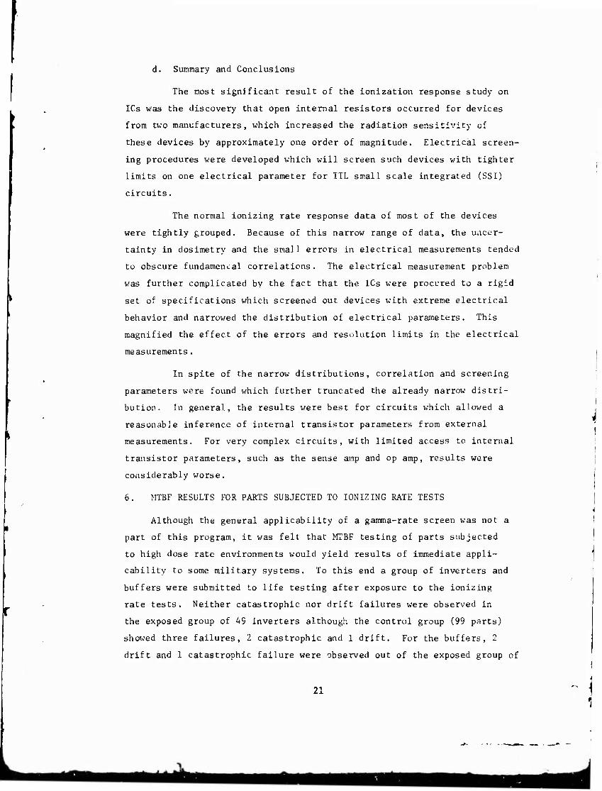
d. Summary and Conclusions
The most significant result of the ionization response study on
ICs was the discovery that open internal resistors occurred for devices
from two manufacturers, which increased the radiation sensitivity of
these devices by approximately one order of magnitude. Electrical screen-
ing procedures were developed which will screen such devices with tighter
limits on one electrical parameter for TTL small scale integrated (SSI)
circuits.
The normal ionizing rate response data of most of the devices
were tightly grouped. Because of this narrow range of data, the uncer-
tainty in dosimetry and the small errors in electrical measurements tended
to obscure fundamenLal correlations. The electrical measurement problem
was further complicated by the fact that the ICs were procured to a rigid
set of specifications which screened out devices with extreme electrical
behavior and narrowed the distribution of electrical parameters. This
magnified the effect of the errors and resolution limits in the electrical
measurements.
In spite of the narrow distributions, correlation and screening
parameters were found which further truncated the already narrow distri-
bution. In general, the results were best for circuits which allowed a
reasonable inference of internal transistor parameters from external
measurements. For very complex circuits, with limited access to internal
transistor parameters, such as the sense amp and op amp, results were
considerably worse.
6. MTBF RESULTS FOR PARTS SUBJECTED TO IONIZING RATE TESTS
Although the general applicability of a gamma-rate screen was not a
part of this program, it was felt that MTBF testing of parts subjected
to high dose rate environments would yield results of immediate appli-
cability to some military systems. To this end a group of inverters and
buffers were submitted to life testing after exposure to the ionizing
rate tests. Neither catastrophic nor drift failures were observed in
the exposed group of 49 inverters although the control group (99 parts)
showed three failures, 2 catastrophic and 1 drift. For the buffers, 2
drift and 1 catastrophic failure were observed out of the exposed group of
21
1
48, although the control group of 94'parts showed no failures of either
kind. Converting the catastrophic failure numbers to failure rates at a
60% confidence level results in Table 76.
22
:y
• 1 fck AM^riMM mma

O vO z CM
o
< x.
CO
•a ca n
00 o
in
O CJ
CO «-.? r-« —. r- -T
o »p r-i O J->
^ o o
sC 00 J, o oo
r. u-1 «Z-! en ■H C>
o 0 u-i u-> ir> T "~l o o SS r-i
o o o rj r- -T X> -j
c. X> -I 1*1 „-1 C O o o f 1 ': ' -.
-J f. u"i r-i <r o c o o c .
-. rl -' tfi a o o o o o a o O
OOOOOO OO
o o X1 o c1 -t * —■
f*w o O » o w r-i O —« '-4 OOOOOOOO^OO
c a> M M 3 O O 4-> o
& tfl e
•H M P*
o
o o o o o o o :
..- r o o r .T~ N B T) Ji ^ 5* O" 0* CP ■
u o 4-1 CO
■H 33
tO vf iD —4 (
**1 -T O fi '
3 O O X >■£> ü o O O O C
o o c o o r* ;.• c o o —
2 a.
23

24
CM CM (M CM 55 CM
U O
5? O ti!
E n CO u
53
o
m CO
n l j O
p- «j -^ co r- i p* sT -i O ^ t
•-tc*»irtu"»p*',",("",>o I O ■* *•» O O «"* ^ ""* t
O O1» iflijl »vtiflMNOV'J I
'-J © 000^,^,o^'H-' I 0A'»OO-H-lOP^O'-,r--,a3—' I
.H O O —tQO-*0-<-«0-*-<-^ I
i 000OOO"Q0-*O -'-«-< i m fl\ ^ I r» O -T PI 00 ^ »j m -J O »■ I
000OOO00O-~<Q--''~*-H I »O >N P-m»-<»T'-<OO'--'DP"1r>00,^-tn I P)M 81 «1 PI -7 n O iT, ^ i Q, « H o rt | O'-« o o■ *r> g o o ö o. ,o o g -* -♦ «■*« t
H o> H O) ri " M PI 'i I« >£■ o ii s o o> H I ©o —t o o o o o o a o o o o --* o —' , t OiH^plNi^O'iriPv^nn^« o nfin | OOOO^OCOOQ:3 00000-*0-+ I ft i/i P« vO >1 n •> ■• .() ^ * ^ O ^ ^ M in Cfl B 00 I O O "■ **' '■* O "* O C —* O P J ^ -I —' -^ CTi "■* 1 ""> i OOOOOOOOOOO OOOOOOOO <H I I o
I I ! I
ft Ci —i -A .-J - I - t -J H H H r< >-l H H H >H r-l H >4 rl -H rt H >-( H H H r4 H H H -4 M"H H H; <-l H | OOOOOOOO OOOOOOOO OOOOOOOOOQOOOOOOOOOOOOO 1 l I T I i i i.;ii T i i. T i l T i i l i i i t t t T T I i I i i i 1 i t i i I I
bl fl ti) t'- U! b' b4 tU W W W [il :■■' .J U J) U ffl b. L-3 u) b: tu bJ bJ W *JJ U) j! u] u.; U- UJ U4 bJ uJ W tj] u { lA ui -< CO "'1 •-] <7, u-, fi O f- ^t —< 00 u-\ -i (^ ^i !1 o r^ -.t -H er) in PJ (7^ o ^ 'j P- •' H ti i/i n 7> Oi Pi I r"'00-l'IPIl*,'TiO''1'CNN*^(J'0-<Wfl^'J-1iCiii^l'00<0\0H'-llN^f1-3in 1
WChHHrHH-<r^ HH-(rH^HHrlrlNt'iriPJf4(S(SNNriPIN^N^P^nfl(nnnP1 I
a c <u M M 3 u o 4J o A PLI
I u
As
0° ■u CO
•H 53
OOOOOOOO i^iinp-t(7''*l'-<'^«ni/,»O',*u^-J'*l'-''*,'^-<T''"*OO'^>OOO0OOOOO I
OOOOOOOO PJp^.-(«-<*Hu->iAvT»*P'»u"i-T»i>Xini©ma0inoOOOOOOOOGOO •
OOOOOOOO-» -»rj<*>( O^WPlm * t> O O ' I O O O O O I O
o
8 ä

s?
5?
-J r-i T> "( (— -1 r> <t Wl J~\ Ju T o •ti ^
O o ■ 1 O CO f\ rr> -J
CO Si u o M a cc
o o r- r] ■ i ro T- in "t
m r> in ■-1 ■P n —' ri
O-l M in O
Ö o
rt rs 00 m ii ■T to -T -t -< O —i O '■!> o O u -■ '-J o
< O CT\ CN 53 CM
M O
<n
CO
^"s •H
v^ 13 ta n
o\ o rH
X
O *
4J « 0}
c
u 3 CJ o o
—< O —t o o ■—. o r o - • n —. <J f*> ?■ rt 'T O <T>
-t o •-' o c <*) i i r-> < 1 f-> o O O ■P ..-, 1)
-r> -•< ,c M O ( i -4 —■ >J3 .C lA ■ 3
O O O o o •-> O o <—> o o o o o o o o o
I (N M I'Jfl'l NM M IN NM tN riMriMTJCN r» 'I fl -J H i-l ^1 ^rt-t'J-tH JWH-» —' rH —' -Hj O O O O Q O O O OOOOOOOOOO Q O O O O © O O O O O O O ■ O O O O OOOOI
1 I 1 I I I ' I I I I I t I 1 t I 1 ' I I I I 1 I i I I I I i I I I 1 I t I I j l'l l'- Li J1 t: W W t; U U) W W U] Ul li] CO lu uJ JJ U7 US ul :>J U IÜ u: W „U UJ t-1 [xl LI WPU1 Ltl Id UJ Ul I r. T f I is ^ ■ i M m r.| c^ -r> <*» O r- -J —< uO . -i el IT. -X. —' m ty. ri .-; -, .t r- •-< »A </; >--i vD O r^ f- — .7 I fi s I-J -7 to 'i if o^ M >o c -1 w H i^i o> n * o ^ f~ o o o H -t N 'i N * f" " -l -t -t «n «A -X- >£i
PM
4-1 o
2 00 o
-1 -4 vt IA LA vß «o >o T~* r 3- tf> (J. —' •
OOOOOOOOOOCOiAfi-5 HHrn-t t,i*ya^'X>fAOcT1'~>—tr-i^'ü'.COOOO oooo
O O CJ O C O O O O O '*** CM' f| Oi 00 rt <& -1 ''~C^^OcO^D^A"''-^rt-HOOOOOOC, OOOO
.OOOOO^-T-Oi tHHOOOO OOOO
3 00
25

•* ,< — f<', »» I
« ♦ I < <N I > (VI I O it O II
• IM I > C ;l •j I I Cui
• * » t- • I I/» IM I
I
2 UJ I •a f- • UJ "^ f X O I
♦ I -" I'
I I
I <^l I O I
^ 1 I
C IM
° !
9-
r» r- fr tf\ •* rf\ <c o s Ift ■» •*
1ft -"• o Ki\ !**■ *f
>J- »A 4-4
m <M >r
D ~« m i*- n m *M <>j
*•» r^ *-
>J O p <■
lS
rv
O I
IM .0 0- o i N v»- O tr *— | ' ; i
•-I p-< o t-< j 1 j fr- •J? *t *o u^ ' ;
,-n O 0 _! , t «-• -4 r*4 o ^: 1
1 1
n C> -i •c J- i : ; -0 o V* I.TN 1 1 —4 •■* o O i 1 *> -O 1- m v-4 17- i i * IM 0> *J ir> r-t ■ j
3 ~ o o i_> —4 ' i » r m in vt a JLJ 1 i i r T--» l/> .f *j ^-4 i
^ --• "5 o CJ -■4 1 NJ <n r- ^1 r*- f- j r- c n ■t ■f r-4 1 b o o a CJ r-4 1
; I p -1 -J <<\ o> J) f- 1 t f r* C* fi r" .--* cc 1 I o o o o O * 1 o |
f> .» i ü» m » O J r* -J <*i ~J- .o u"\ ^1 IM -n ^-4 rr X ; •-H r-" 3 O "5 -1 "3 r>4 '*> o IV !f» 3 O D n -4 o • T *- ,^- /J .rt o fi ^ •* -* IM -*> in X> r. .-- X t- ! »-« ^ J O 3 O _J c c> o o 0 o « \J o >n VI in —i >c •o 3 40 ■n "•'! ■4* O O ;
< <1 o -. J 1*1 —4 4-4 rv J -'* l^ 1- f- en f- i 4 -4 —J •-4 y O 'J o O O :J c c; o CJ O
t- D -J ". X -T ., ■ \j _^ —* -^ -- ," ■ .' N .-< ( J —4 "> *\| -4 *-. r-.i ^i ■r\ <c\ *- T. 4" r- »-. .•'■ N-
-4 J ~> '- o 'J o C3 o 3 O c 'J. w- "3 .> O ifi n *> * o r~ in 3- ?'< J* -J ,-« rj •0 o (\J f ,^ r', **. •*) C5 -4 n —4 r> -5 M r> ri ^t —4 ^ •N. ■n o .T o r- n o J> o
o <^ to z CM
o
^* «
o O i-l
X
o vO
c
M Jl O o 4-1
o .G
ET « B •H
(X,
>4-|
o
% u 60 0 4J W
•i-l SB
I I I I I
i- I X 7T. I at OJ 1 Q. J I
«M (\j fNj ^ r\i f\J (M rs! r\j PSJ f\i r^ r^ <vj (\j (\j »-I ^< ^« --< ^-4 —4 -^ rH -■ i »■ < . , --• —« *-4 ^^ .4 .-4 .-. r-: —• ~ -1 ~* 0 o o o o o o r> O O O O O O o O O C> O O O O O "i c> o o o o 3 O O C O ") o - > "5 o
1 I I I I I I I I I I I I I I I I I I I I I I I I ' I I > I I I I I I I I I ' UJ UJ uj lii UJ u1 'i-l J« ui LiJ ji ui 'U UJ Ui ui u' '-'J LLI a' LiJ u.l UJ MJ ui A! ..'. a> u; Lil üi UJ at JJ IU J u u ^J ?M (.'^ if- '4 T >r "* ^ ro c> -r <".. .7 -^ % ^" r: : 'vt- "•■■ '" vi ^ o ^' -- -g a. %* i.r- in *-' x" ' i *" ^ > * ^5 rf\ «-4 r*- rg .0 j . ^ H o ^i r- 'i T ^ '- C' --4 ~-t ,\> ^j :--i *j tu- .n r .0 ^ 1^- a" 0*' ^ ' r> ,--, -. ^.
••• H N N PI l« >J idftvUNMStOff t <-4 »-4 * 4 ■ (\. \| '^
O <J O O O O O O O PI O1 H -4 O tr. -t a*\ -4 i, X ^4 u-'! P4-i c
C C? D '.1 a O O C O r-4 r-4 .\ (>', ^ *\.i -t t| ^ Vi T'l lw f\J *- .-,
^ "i (ft < *o o o ■
-■4 »\, -4 n o o 3
tN m a) 3 00
•H Ü4
O O O T O O O —1 O fs4 (n u-i L^ o "j fi o ^ 0' -0 in -t *\t -« "M st -4 N TM fij -4
Ai ,4 -l O •> "3
26

( I I I II I I I I
M I — I*- I • ao I t • I < 4 I > ~> II O il O I
1 • **> ll
> O I - ' I O •-< I
0- ;!
• •* !> O in ii i- • i tn N- i
i »
»M I O 1 I I
2 OJ i < US I UJ f- I r o i
> i
IM * O I
2 I I < -J t -. O I a o i lii o I
i i ,i i i i i
o I -< i -i i
i o l
• i
OJ Ui 1 a. o i
i t> CO F^ 1 •P tr -f 1 * r>j ft 1 £ J tf *NJ /-* I »/• *. o- a 1 o C rC f. i •* «r. c\i rn i to m O f^ 4 t> . o o o ^ ■X "j 1
• r ** -r f^ rv* **> ! ■ ► 0* m G ^f r> ^' ) o c- in m a fvi •~* ■r f*. «■, m rsi f* ** ! ir- r- ^ ^- CO rNi *f *
1 «s r- <r •4D r- H r-< sO n CO rr\ •^■, fj ri •* (^ 1 ♦3 J5 a- •-* r- i^ h" r- »\ *■- r»t ^ h- «r>4 Q m
< P r<i «-, n (M ffl C- m ) «5 r o x tn *-* *t <7 :*% j r-i r* <w ■n ur» ^ a -J) X
<«1 an P-. m po fN. -NJ fv —1 ; ■» < i U" -N; f*>j o r. : PÜ r^i sO j 1^ r n-' f. j. ■i~ J- X C- si>
■ e,' ■s r^ m f*-; (-•J fM •" «~. •-t
i f\j 4> «rt o M t\i r* ir ^4 o (^ vl* I (SI +« "■^i 'g ■J -i> X f o m J> sC
n« «i en rr, CJ •'■^ r. si- .■*! m .-4
wA (?\ —t a %r 1—4 -n cc .•»■■ O -^ i;
O f - •'^ D .^« .£ »o -n a. si U u"i m fvl f^ m i^i *"vj <">* - n (<» .•n «-4
a C sO a.» r- a. C <» •C ^ r- s."
1 0 f u O o j> r- x *r\ !>•> «M li-^ ! (N, M ra r*'. Wi <>i .->*■ r* o ^ ci -H 1 f\ I f -0 *M o rü ^^ ^>- *"j *-t sC U1
\ C- I T\ o- O r> ■n .-i «\ ^-< ^J r j I
j (V CM *M "1 ^i "J ■J f r^' ■*"■. en —t I -* m r^ >Ti ^i -a 4 ^C J r^» r—
1 c «\ u^ OJ -» <r r- *> X. —t -^ c
IN *J. ^Ni ~vj f.J n. —* ■« ~t IW, ■^ •-4 ! -t p f <^t *-* "J ^ o o cr —4 ^-4
r- us •O r- 'X' J- ■Ü c r* O 0" ■n i (N ( \1 r>j •■\j '•4 fj -•i *M _< •VJ —• -^ I o- *• o r**, ti («■ -f- T .— ^' *-- ■—
o tf •;J O r ■o s^ r: 'C ^-i t" r1'.' IN V ^ lJ *■ i r-j —* i J .-4 Ni —4 «—■
i -*fc >i .r» 0 •Ö <V k ■J' •* -.. >s-
if ^. Jv *- -* *i »J U"- r* J^ ._. IN iki «*sj f^j r-i . si "4 . r-t -4 1 --*
i -r I sO '■ J ■r« -J- <"J 3 00 —- .? u*. ,- >•♦ * si .n «-. •—< o • j"l ■A *; 1-4 ">
i -s; IN (Ni M ^, '■; •—I « -' . < —t .—i -' -V X r-i r^ r»i f*'> s. J 'C O 4; r>. ,."
i •<S tv\ o". ro .r i7 T- rfl ■£ sj -". .-( »-I
w » \J <NJ \i f\i ^-4 o • -^ —- IM —• _4 -\ U 1*- u" CJ r- -I -i. " V ^. ■v -4 «. IN . J f-1 .-» <r X» «^ /I ^t 3 Z- f- ^. i (SJ (N f\i 'V tM »-* t? " .4 - i —* O — 1
! rr i. sj c I— r- r> r> / -- '7 r* '\J <"* 1 J ■n O ^-, .*■ r~- .^ c O .■; " J
(SI \i \j f--J i\J .4 O -* r- O --* O —-* j -<« ̂ '7 a- i.) U^ "^ —* vT r ■• —4 iTi c
IN 1 M "J o -n -sT *»■ . rg •-- '^ v: ^•* r* ( J l\J f\J ■-sj r-» o - --4 J '~J .j —4
US a. - 1
IT. >- >sl -*-, i , is f' j- —4 '*"> O
a- -i « .-< a ni ^ n ' h ■—« O r** .T _■
e-' iM >Sl r\j '^ fV, ^^ c ■» -H ' ) r'.* O —4
m ns ifi C _> r- r-. r- ,) C.'1 c C\J i) ^T
o O O o ^> f- ^ .n c f"l l-'l ■.* iT. T,
i- to rs: rg r-i Cvj 'si o n> ^-< 'J '5 O .J r- *-< H •s? OJ o si/ a.' f»j wr-< " 1 TsJ --4 r-
r4 ■o O C' o f^- > r ,-~i c l\, !/» IT '-* »•> (N (N •J "M r-* ^4 o ^ O • -< o O O 0 «N |T> .n on cr ft! a-' »-J f\ n '■J '1 O J->
fsl ■O i> 0- o O n 'D ro in O H sj sf •0
f-J <N —* ~* -H ^i «~* :J ~> o ^-* '"J ;) T) :i tf r> -J ISJ ''j -^ .o -> ^- o- -o T: 7"j -~t c M J o- c- ^T« 00 U"1 0 NJ 0- ^,' —4 sT >t •0 Aj ■'S! .-4 - -4 o Ü j—* -'. ' > ' '1 *~1 r.1
"■ '3 Jj 0"' "H .-1 (NJ «1 *.) ro T. ^: ,f r> - -. ^ ^sj
T T -c c- -r 'a" »i .7« r.i • vt *": ■0 -M .»■
r-i w~* ,-t —4 O O —i ■3 o * 1 o ■ 7 ' 1 O 0
i s
-< O ^1 (SI
^ 1 -H o cr -vi ir If -I I«- 1 il
*N (si IN (N (v) rj -J ('j 's] fsj -J g I'J IS' >J r- 0 a o o o o o o o o -"> noo o ~
1 1 1 1 1 1 1 1 1 1 1 1 1 1 1 1 u.i './j m m uj i.u uj jj L;I in u. IIJ u.1 11. a. ui i* in u' aj u t.' n .i t p. i - .. r? ir - • _ . 1 f- -, *- •. - - n .]
'"J vf tn ;- oD o —t -s .A so -1 7- .-< -si + _n ^- -r.' "S «^ r
\J -g N (sj fM ,-vj r-j M -g ~j v f. 3 O "3 O '; 'l o O "3 n i 3 I I I I I1 I I I I I I
\i IN (\, rsj ".' f., -M -M ~.j 1 o ':> o o o • j -> • -s -5
1 I ' I 1 1 1 1 I
—« " -r o r-
(sl CN <N (N .-n 1^ m -t ^f .f j J * m fli r ;r. us ur. o
O O O .J O O t- -3 M3 I
O O O O C) '.' : J ! . O O -•
J^J■'C4JSOJ•00'', (\-H.-I-C .1 • ,\i ..• 1
.(1 j1 0 -o (^- rj> ir Lei -i» LTV a i T'I -\i -J "' .-1 z
;■: ' J \i r, ;M .v, o fM
^ o o '' > .: -J >'J ^
rj n n « -j ^ o :> T „'> r'i H H :s ^j -£'
OS O
z CM
U o
<4-l
CO s^ ■v a)
C OJ u u 3 CJ o u o x:
CO B •rl u Pi
M 60 0 AJ to
•H
iro iri
HI l-i 3 60
•H
27

< in o «N Z {M
S
z «M
H O
«4-1
4J c e u 3 O o 4J o IX
J^ n «9 6
•rt H
IX
'i
u c
c <u
0) V) o o
u-i
4) M 3 00
(V«) INlHHfDOlOM iWMISd
28
Jk

(v«) iNiwanooioHi AHVWIHJ
29

I -f IT
I
C± >- * c r w »V & I
o u-i s-*
-id CO
4-1
a to 3 *»» 0) ^~. c
•H 01 10 > ^
j
•a en « K ^-N
•H CO CO o \/ t-H •a
Ctf X h O co • o m .H
H X <:
fl ■t • a m P. i—J
M a * a.
p § e «0 o ed BC •H PJ Q vO
o> >j l-i vO pc (U z ■dj ■w ts p*l 4-1
S td SJ o o cu CO «4-1
vO IT,
01 M 3 M
(s) 3 '3HII 33TO0IS TVDIHI33T3
30
Jk

.. g
-I T
3 i < i
A ST
?
- *
- f
- ! _ i
r -
- r
vO
z CM
o
o w
S w
• 2
CO
CO D CO u 111 >
, o
—: s
(s) si 'INVISNOD awn aovnois ivomoaia
O r-^
CO to
CO
OO
P. P.
H
s O
PL.
PI
U-I
O
60
0)
u CO
in
<U U 0 oo •rl b<
31

1
x *
» u oo ■5- t» . O O . _0 . iy?n . o © . C r- < r err t o o . a A - UN» O O - ■4 •* M X- *- - oo-
O O ~« r ^ « f- r* «n o o -* o -o o F*- .Q »** OO ^ «0 •* »- <p -O »V o o -^ up ry ^ C <r rg O O -* (n -* **» Ü o *>* O O ^ 3D J. £?• ■piAO oo -■ ■e -^ * ,n i/-, t» OO o
CD «T1 -* <"t sj C if i a» u £> o Q m Ifl o •-* V if. lA t) o O o o >n * a: o f # f <r o o o o
flD *, -4 f» O O O O
*- i, .f o o o o o
w o o o **■ OJ —< CT" i/S <M ■* -J o o o O K. 5 * o »« Si rn * o o o o ■$ $■ r\( rf\ >1 ^ K) ^ o o o o i«-. qo 'J O
.^ -- "N4 r
O t» O < rf> # ^ I -* *4<>i t o c> O ( •n («j <u , -• -< —• f O O O c 0> X - o o-
> o -*
i (Ni O O ö o
U oj Uf o o o *■* « o OftiO
iA -'S O O O tf* o — .-# O O o rt c -* o o o o o o oo o
UJUi Ui o o O O -j o O rf% o
* -« tr OO -* o -■ -* oo o — o -• o o o o o o o oo
U LU iJ Oo o Or* O O tf\ O
oo o «■• o »•* O o o o o o oo o
Ui oi Ui o o o o o o o ff- o
to
Ü
> a) Q
00 c
o
1^ o o 00 < H u o
W
f\i O ?
a.
rj (•* m tst «\j r*j o o o O O O o
a» LU li f» O »M
U' Ui u
■^ocooooo; i i
J uu U' I i -^ a« *
JOOO^OOOOO^ I I I 1 I I I t I I
ui a' UJ <-' O) U.» U.' UJ U' u ^ M tr K c, * N o ofi o
O o o i T •
uu U' ui
o o
c o
OO OO
0009
o o <
o o <
t r- a-
I
i O t*
1 ^^ ,«« ry r\j r»j r»* ^ f*i f»j (\' ru <M
> o ^
f» O f
X O r
OO (
O O (
»OM-r-oOOCJOOOC-'Ot
) O O O O O O O O O © Q O <
000006» i i
\ii05TO^»^(l)» o<ttc*o-*»r»oooo<^o
n OS* 0 0 -*
UJ o 0 0 or t4k~r4 < 000
000 -*• 000 »/• Ui 0 000
*« O (A > Ui U. 111 UJ
OOO .-> O *M O
0 O «N O •jr • • •
-* -« ■-«
■»
O -j -*0 -A -J O -0 + 0 OO^ u. OOO
•a n h
01 1^ 4-1
O c »H 0)
h X n
3 O Ü • O m 4J
0 4J £ «d PH
O- » ft u M 3
0
O 13 e
ä h
0
5 60 O
1-1 J5 (0 4J
1-1 •H Ä »
00 if)
9) U 0 00
£ S8S fa
32
itf ^

a I
5Z
a « act
(V) I •lN3HUnOOIOHc[ «JVWiad
33
r-^ *J o o
00 <
**" 3 H
*> 0) u o M o
V «4-t r\j >
r^ •» ~* o CO UJ a *<. O r. /-% 4, •^ * •t C/j
["! V*' CO o "0
~'e ■H cd 4J OS uu O at
% *" H f- • U o o i pa G
i) t-l
1 -z V X c
! "HT o o
■ *.s u •
1 -H nn is ti 4J
a a
a) a
z CO
«s «9 W u
i go IM C SI : °5 n h
1 "H u 1 "*P- e 3 1 O § U i ° P O I 01) «J
2 OT $ «
cd •H
o St
P PM
U 5* 1 >o 0) M i "" U cd 1 u, u <3 ! 2 cd •H
u M i * w p-l
• ON in
t) s u 1 3
00
fn 1
rita_4 ▲Jft ■MM

♦ 1 :
♦ ' !
1 ! r k
| j
i! ; ■
I I I
of 1 i '■
. O 1 . 1
u.
i j
* 1 -
i
I
1
1
;
'
t
' 1 1
1
i 1
1
K S ■ j i ! UJ ©
+ 1 ' ' i
o j i ; «f • ' j ! i | ;
* - |
i 1 i
4 ! i 1 j
it | i 4
i ^ ; V i | O 1 •
OP f\* ' ! 1 i *-4
-■ 1 1 r^i ih
1 ! 1 J i
! j —t
• © * j i 1 f* */» © 1 1
"* i i ] | I
1 «4 2 •i. I i 1 I I ( i ^ J» t j ! 1 1 t "Ü
1 t 4T
| i 1 -> i 1 1
1 l **
■ * i [ 1 1 i "" 1 i ' i 1 | 1 - I J j 1 ! ' wM
1 «. : 1 , ; —1 u> * 1
1 •N -*
y * i [ i •* j i 1 .-« (St
1 1 [ f\ *1 M 4 O • i 1 f\t
> © 1
i 1 ! o jh
♦ I
1 ! j .
rg
1 , i \ ** ;o i ! 1 * cC • X * i 1- 1
i 1 i t
1 »A i <M K *-* * ^ O
OD i i 1 i 1 01
IM ♦ ; 1 ! i ! *■
U. 1 j i i i O - I f 1 i ) !
r ♦ i »- 1 1 i 1 o • 1 1 l i ; -J* i 1 t i tt. I E ! i i !
* i 1 i i t
j i ' ; j i 1
i 1 !
o 1 o o i I | § i O % o
o O i U <
O ! o . ; ! v ! O s o © < > o O 1 «0 ■ 1 <M ö an -0 f ; fs» ; • [ • • • I • • «
(V -4 ! " " * ■4 o ° ' 1 > o
1 =
o o 00
* u o
«4-1
'S u
o H
X o
a. ft
go 3 to u
«
o
§
n V 4J 4J « u
o vO
V (J 3 60
I» •
(v) i 'iNauanooioHd Äwwm
34

o
I I I I
'I — I *f I ~ «f 'l • f«J i
a. • !i
> -o I O I U |!
> O || UJ I o -u i
U o
O c\. I
i/llf l
i» i O l
i* «3 *n I UJ r'l 1 3" - 1
• 1 <X> ,1
1 1 1 1
r- i O 1
Z i < M 1 t—i C 1 3 !\ | Jl X 1 x: • 1
-0 1 1 1 1 1 1 1 1 it
y- ►- I I I I I I
i- I ct 7 I .11 ULI I a o I
I I I
• I O I
«* «r
6- c* 1 i t- «■ 1 j
<P •-< ! * >0 i j « r*^ o r-4 i
r~ f ./\ i t 1NJ t ^. * ; 1 m f -? ! i o t-4 s • i •s\ p o CM '?' o« F fi n O i a o r-4 --) •-< , «» *' >r o Ci o- i
a & '^ .J- C\i O ,
o .-• •-< <■* --. ,
ro >J- r. >-<"l »^ O •-• , a? tf «\J vT fi <M 0" i
o p wA r-t —8 -H o I *^ fi CT I"! •u r. r-. CD If -.» fO .vi —* X O C -4 •-4 •-H f— Cj , r- 0 x> ft o h A j ! r- r-4 m '_ > .-* 'JO o P ■~4 »t -* —* O m r» r- aj r-. vN 0 I^I
r- fi 0s '."> O & r*w £*»
o o o —< «-< g O •H <\l «-« •n O sO m CTJ »—■ T^
r- #c r-- o en a: j~* «SJ 'si '\j
o o o o o O o .-4 -* ,H o o r> n 'M >0 n ** X 0 a> .0 ri r- T) to J: «i ^J tr .-( r\j
o c o O o o o r-4 o ^-i »-* 0 *r <XJ O :o -( 0 1 i— f- *c ^n f\J -Q Lf\ f- *J f+-\ w-t o o x\ O O ~> o o ^"5 'O .-) o r~-i c «J o L* c .-* f\l '^ M ■i\ "". nsJ J". c \JC\ ^J J rj j- ^ <■ r> ~* .." -J J"' \f1
o O O O u —. c: *.j o o -j o o .-• y- ri , 4 ■7 C*' \ f* *- * -■-, . t l'1
**-■■
o ^ «■■4 • H , , r>j O v? *-^ ^« r<> -A N- .n r ' r-A
w o o •"■ ~- o *--i ^ c !> ^J ', ~- "' : O J3 01 c- r- ■*o ^ r\. T; '•J r- .r« •*> LTI it) "',4. ^ N O
C -i r> o -> •\! ■^ ■^ —* —• rvt •VI r* »T «-.' -■< *NJ T "
-- -n h- K f^- r- »>. t- ^ r^- -d o P*- K r- r^ P*" ^- l
oooor^ooocooooooooo
ui a) JJ i_i u' UJ u1 u! ii." .u in .J uj fj JJ a. uu '.■; ' -J O :N cr o r^ -,■, v* r *~ .~ -4 -*> -- n _*> r- r,. tVj ^-f ^ w'\ -3 vj O c1 i' j T r '- <:■ 1 *"> ;'■ '- '
ii -t1 "t~ .1', -0 ■" :<" n; ■ o o o -■> o :5 r- o
T: -rj rr T- ,-;: i- ^1 '0 er cr O C O O Q O C* O O O
-H »•) cr -T) r- o r\ m vj —4 ,-■ -1 ,~,
(JJ u .:: u; 11 ^ ■ 0 ;- '-1 '■* c i-
-1 ^' "*- jr. r- ■*?
—t r> ,-U vM ' ■j n -n «A
o o ' ■ ^> o o o o o o o ro m: eo •> o n o
o o c a3ocoaoo-iJ^'v«t-K I X c
it«, h- r- '"> r^
i -J o o -j •:
obooooooooo.-j«tmo>o-< -«NHH-«
N N ß o i« ^ ir\ o (v .i I cj o o c; ■-» o o o
P. m
G 0
es 5 00
■rl U <U
•s
3
c o u 0) c a)
•f "0 V u M O
c M-l >H O
§§ M 00 00 <i O H *J (0 <
• H «O
1) Vi
tu
VJ

5 i
ii i
.1
5 ;! • ■£> I
of • 'I < •»• II > fi i C |l
° i!
J >o « UJ '| Q "J l
O- I • -* l
Q O ,1 t- • I i/l <M |
l I I
K5 'I i i
2" c; I < f- I U- fsi t n "o i
• i 1A |
I
O I 2 ,1 4 Ui I — => I u f- I
SE • I ■o ;i
K I Of Z I UJ UJ I O. U I
"3 7.
a
OOOOOOOOOOOOoCJOOOoOOOOSOOoO^oOOOOOOOOOO
UJ UJ U_ III UJ ii.' "I UJ UJ Ul III 111 UJ l:| Ul UJ Ul UJ L'J Ul UJ UJ UJ UJ UJ U U' flu 'JJ UJ JJ UJ UJ UJ U-l UJ UJ O.I Ul ii o p- r<- in r*- o r-; r\i JD 9' CM ir. '• <v m *r> *M ir\ on —i ,j- -r , a -)■ f- .-• ? r- ^ T *I r- •-« .r — t T* ,v* -I f* M ^ f> N £ ir- ^ »■■ H 0 O J ^ -»»^ M ^t O tf\ ^ (^ -o \ M1 .-< u 'J' O T> ~* »~i (V| *j o** -A ri *t
N H H ai 4 CM ^ (O •>-* t~* <M f\j <*iCO m *t *t m m «0 JO «0 P"" r- 0^- .V CT* U* (7> ~* •"' ■-I »-1 ~* *•* -I <-< •■< .-I I I I I I
O o O o O O O O o o O .<<( O O o o m m m nv r- o r- o O n o■ > otioonoooooO^.O'txi'jHHinNi^.Tji: .r *\;
1 o -j o o o o c o n> o a ■ o D o p o a o o c o a
O000OonOOOOiHC»Hiv«iMMKlrtO»«»»»l,l''JO'536aoO353O
o
o§ M 4J »^ «
n C 3 0 00 1 -H
6'S 9 O H O
H « O ca
«n «
«f - «1 5
J-l ■O O f-l J2 O OT
u
o «W «si o P2
§ c K 0 CO M O « *i -rl m tH
■H O 35 OT
• VO
«1 U 3 to
36

o s 3 06
O
>
«S 4) U
<2
.-I O x:
CO
8
c 2 H
3 E
g $
K C K
a s
e a
§S
3 o
§ M M « n u 4)
y
en
**;
[8/(TB)PBJ] aiVH aioRsamu. Ho-tram
37

n
m e
8 is
a g
S G **';.; »,1. :* 4
3 3 ♦-+-■
a o
w
H CA
W -
8 * S w
§ 1
o s
o
2 o ■ 8
? S 3 H
2
8 « Q
U
O
8 a
5J
[•/(T«)f»*l aiva aioHSMHi No-romi
38

-f- --
I o
JG B
& £
fl ß 3
< H
.-1 3
1 «
M
u
> < •s.
I >
8 V»»
> e « *<
«H o
J3
O o
8g M * s?g
< as •H
M H V O W OT y at M
U o OT <H
• m vO
V M 3 60
[8/(TS)/P«i] aiVH Q10HS3HHX No-Nanx
39

■S <
5 8 ft S
' O
3 =
O o
2S 4. * - u .
NJ -- . - , -
^-*
.J..-
a o
i M
H
S3
§ § i o
g o
«I
I O
a «
5 I
fi 9 H
3 C I
is I! SS • O M w «i
a e
5J
s s e
[B/(fB)p«j)ajya aiOHsaam NO-NHM
40

1 10 — a
10 DOSE RATE, f [RAD(Si)/SEC]
Figure 67. Superlinearity of Primary Photocurrent, Ipp as a Function of Dose Rate for the Dual JFET
41
■4*d *+m+ämtih «Mi

- Y
a I
-I
o*
+ *- — «• - ♦ — -• V — - * - • ♦ — •
-
- « - * —
:
-"-♦••
-
! ! !
1 i
i
j
[ + • -
.. rg
i ,
j !
i
! i
M j j ' »
!
1
-4
0
~*
! 1 ! !
j ■ i ; i '
i ! 1
j *0 ft I
! | i a
w
S X
;
.
!
to «•1
1 i
j 1 <
■
1
w
1
| :! i i ' !
1 1
i !
a 0
I 1
i
!
1 l
j ! i t
[ |
1
i
j i
1 ~+ i
1 ! i
' >
i I i
i i
i i
i j
I i •-* «H • ■ ' i
1 } i |
1
i ; ;
•**
—* 1
- r -
i ! 1
j {
{ •
! 1
4 1 1 i
1
I
! i
i : i
i -
r-«
i 1 i
1 1
i
* | i
i
! 1 1 1
r* j
1 , - ♦ _«. - . fl -. ..
6 e i-l cd
& ai X
o «t-l
p. p.
la r\
W CO o CO
Crt ü
o u "• w - < (A B - O a)
*-> HI
§ •H
0)
o O
00
0)
3 00 •rl I*
(v) ddi
42
—h J i - m

—» 3
- I
_* « c
IS t © I
3 O
<u x:
u o
U-l
CO
I Or
o
! ow
i 8 T ~ &
w
ID CQ
O •H
0) f-i H o u
(V) 6/(IS) P«J ,01 x L IV INaHMOOIOHd AHVWIM
43
*M^k4rifti^ MHH

o
> f* o
O X. (0
u
^.1 r\j
01 (0 c o a (0
m o
K © j- ■ w n\ -l • ~i © o - ^ v o < -* * ^ •
w* IA■ rt **■ «■> - -« t* O * -i r ■M rH O O O < O ® « «J * '. n x i/-. «r t r -* O O O o '
* m \r -o ~« —« •*> - o •-• o o o o o '
• — r.i o ~ ■a- c —• y- r- ■> o* ■o P-- o t ■i <_■ O u -*.-« « HI r 7 o N ) m U PI ^ ^< « ■«"* t> o O J , .J f\ J N „,
v ^ "1 N il d' < U O O O J ' . . <>j 4 r\ -;->
T f, c\i m r>
> rf\ f\l -J r ■ r~ j O Ci o o ;> J J H\ 'O « l\
o ■rl 4-i
CO ■H <~» T3 01
J
* O J3 i; JE» c * iT
c o 01 ex
.C 0)
O 41 4J
H «0 5S 4-i
60 I O tH 4J 0) U •H 0) 33 4J
u 0) 01
rH > a c g M
• ■ I- -, -1 ov i
H ft| Hi Kl * ^ UMf J Jl (^ M)' i i* o
C' O o O O O O O p* f- -« —* «J 1' n s* vl tf ■ "' 'I' 'r> ' J ^ J- 4 -<f- J f nN rjOOO^OO
c> <"> o C* O O C O O O »j 's) r. J> ii i/\ 3 I- -1 r- .1 j, 4 •-' rvi ' ' O O O O O OOf''.'l)
O
0)
3
•rH
lo-ij«
44
ttt ' i A^

o o X o
60 c •H s o X. CO
m X) tH o .c w 0)
ITl u • f—i x. t-l H
CO <u ■v. CO *-~\ C 5) ■H O 6 01 D.-H v-^ U) H Q <U
1 K 1)
'~^ <U CO
Q to o hJ 4J 4J
o C CO CO iH « i o
I-l 00
^ X M O o Ä <D -H
H 4J H .H H 4J
W 0) 0 CO > 0) 53 C H O M W (X. CO M X
s H 4J •r-l
i5 o o ^ c H a o H CO -rl <; u w N 00 cfl
in M 0 0 z S5 o o M •H P
BC H
OJ
CN 60
O •H tu
siiNii AU naadiN
45
L l«MM

0 0.5 0.6 0.7 0.8 0.9 1.0 1.1 1.2x10'
lONIZATION RESPONSE THRESHOLD [RAD(.Si)/SEC]
Figure 72. Truncation of TI Buffer Radiation Responses with Offset Voltage
46
• - "Ihn i MMM

I • -
*«» n CT x, ■
t —« O O •-* O - < O o ' * «i 4: >M <" O N ?■ ■/"' 1 o *-. r-- > j oj r ' ■.
f\ JJ N »- .f, 0 'Owe ' O . '.> O I
»N 1; ,0 (."• .• ~« f d- j- ■ ■ , '-■ r«J I HCI'JOO'J'j:1",'. ,'I:'J 1
u-t LO »-< r~ j- CJ in .-. x *- -N — — -* " *A . ! I o rsj r- o **"' w —■ J " <■-. -.. 1 .j --, o> 1
,4 ~« -> r o "> "' O -■-.;' r r -1 o , 1 O PJ. IT O "" T. '•■' -t u .• r< .-. - j .) «J ri »• r» j •*■ O f>J **- -J- —< -' '• ■' "i - J -- -' "J ■*" ■.' ZJ ■*• *f O •-•.-* T> <"> o '< ^ <""• ° ">'"-""> ~"> O C o n ^ ■ |
nj a K r> r- *r -t v ■'. f> r v 1. r er -r> v T ** T ~ ? 7 ? 1* c P■ (T- •*- «■ C 0- ff ft- ft- f OOOO^O ■-> -> ' * O >j '. J ■" r- •*"' O '.' ."" <"• O O r, <-. O O O O . ■ ■".* O I" O O O
i.11 LJ ;i. : J !i" u u .J u ui .. ■ '■ ii L,I Vi ■■ 1 ■ j IJJ J ; a- ,f ■,: a' 1., a: .*( 1. ■ a,' u 1 u >:J U1
f .1 / '5jv'f f^ * ' ,1 rj - > "i" T1 **" if ."* *" '.T —i T~ -i": n *) f o- -Vj **■ .' ^ r-i %: -K. *" ... .«• ■■ "> n -* "; "> r j -i *" r - r* »- • *.. J -J -J ■■. ■ f •. ./> ,. ■• T, V C T> -■* —• >.
r^. -> 0 -T >- «-* >'• p\, f ^ X' ^> c r- x a y . • -1 -. - 1 -• •■ < .■ . < •—* ~* •■• »- *-t i'-j rg ra % >j t t t 1
i c> kj .• --'- o r> rv -j J n 1 „..-,..- _, ^ -f. 3 -. j ■- ► ^ c-1 o r- -j o c o o o o :* o
■1 O :.i n O Ci r, r> ~. *- -* - j - . .: ri 7 T, ^ A f *i ftj. (T* r. rv ., (_;% ,4 *• o o -_■> o CD O r-'
O -■* "■' O O •*! C> O r> '.»
C a f/S Of
I
a)
3
O u
w
p
•o ■-I o
J= Iß (U Si
CO
o a U5 (U
Pi
c o
1-1
« •H •a c«
p.:
0
o «J CO
•H X
r--
0)
47
•»»»*» -■» «3k ^^

IHPUT OUTPUT
a) Inverter Schematic Diagram
200
100- _VT„ = 1.2V
3 0
-100
-200-
IN \
J I J L
,VIN = 0.4V
VIN = °'1V
J I I L 0 12 3 4
V(VOLTS) b) Output V-I Characteristics of Normal Device
< a.
'00 r
100 - -VIN = 1.2V
0 - /
-VIN = 0.4, 100 0.8V
200 " - i i I j 1 .. 1 , 1 i i i
0 12 3 4 V(VOLTS)
c) Output V-I Characteristics of Device with Open R^
Figure 74. Method Used to Detect Open Internal Resistors in the Inverter Circuits
48
+ litk

20
15
w o M > w p
c OS w
g 10 •z
%
s^ S
^ I
0.7
^ M I I tSl s
1 ffl !_
0.8 0.9
n
1.0 1.1 1.2
DOSE RATE FOR I = 200 ma lio' rad(Si)/s] sp
Figure 75. Truncation of the Word Switch Secondary Pho'tocurrent Thresholds with h„ and r_
49
i 11 yiw i

sn; 5fl<
»47n
12K f VW—i
VELINE DRIVER
TO OSCILLOSCOPE
125ft CABLE
i2on
1.5V
Figure 76.Experimental Method Used in LINAC Tests
of the Motorola Sense Amplifier
50
i f - afr i

Table 51 Summary of Low Power Transistors Tested
for Transient lonization Effects
Mfr. Device Type (a)
Construction Gold-Doped
Base Area
(cm")
Approx. No. Parts Tested
F3C 2N696 NPN PE No 3.43 x 10"3 150
FSC 2N2222 NPN PE No 8.47 x 10"4 150
FSC 2N2905A PNP No 9.35 x 10~4 150
FSC 2N709 NPN PE Yes 3.65 x 10"5 417 |
FSC 2N3960 NPN PE No 3.65 x 10"5 150 j
MOT MT 7111 Hex In v. 30 T
NPN PE IC Breakout (DI)
Yes 4.6 x 10~5 I
30
MOT MT 7113 Buffer BOT
NPN PE IC Breakout (DI)
Yes 3.03 x 10~4 30
TI TI711) Hex Inv BOT
NPN PE 3 IC Breakouts (DI)
Yes — _~ 87
TI 117113 Bufier BOT
NPN PE 3 IC Breakouts
Yes 87
(DI)
(a) PE - Planar Epi (b) DI = Dielectric
taxial Isolation
51
• ' ' fcflb Mai

IM lO
co H
tn u o
u H
u CD
§ EU
o J
o
4J co Q
4J C CD rJ M 3 CJ o u o
-C
o
& co
1—1
CO o ^) ■o*^ r» r*» 00 00 00 00 tH DN ON rH ON ON
CD *"> 1 1 1 1 1 1 1 1 1 I i i N !* o o o o o o o o o o o a
rmali
ra
d(S
X X
rH rH
X X
rH tH
X X
rH
X 1
rH r-t
X X 1
rH
X 1
rH rH
X X 1
r^ CM a\ co 00 O m 1 <* rH 1 1
1 r>- in i
o" -* NO vO 10 oo m co <r r^ vo o o zl tH rH rH rH rH tH vo CM rH CO rH rH
c ü CO 00 ON CM CM -o vO CM \D co o ■K O O ON CO O ON
00 00 r-. CM O a« O CM ~» m <r m in ON <t <r C» CO >tf ■~~.
X tH rH rH CM CM CM CM CM ON CM r^ O CO in rH CN rH CN CO co CM 2
4J c VO m -* •^- vo m ON r-> vO r-- -* CM NO O 01 • • CO • CO ON M co co o ON -* NO LO O O rH NO m ON in CO O O co o r* CD rH vO ■tf CM H CO rH \0 <t CO CO -H -* vO CN r-, tH <r CM 3 Ö0/-N o o Sl 1 1 1 1 1 1 1 1 1 1 1 1 1 i 1 ! 1 1 !
*J OtJ v^ ON CO 00 r^ ON * m ^r o o • o> CS| • o o • m co • rH o <• vO • ON . • CO
J2 <T rH CM in ON • rH CO 00 o r^ CM r-- CO CM vO ON ON O PL, CM rH r- vO CN rH CO rH CO 00 CN CO rH co CO CM rH ON r»-
> 0) p
■O /-N co oo vO CM ON <* NO m in r-- ^o m ^ <f rH O CM in
CO H CN O r» 00 <J- o CO vO 00 i^ NO 00 CO CO CM ON CM CM ^t TJ **-/ rH NO co CM tH 00 NO CM >£> CO rH rH
c tH (0 u
CO
ST rH f- ■* CM 00 in r~ r^ CNJ vO t"» ON O
c <-> ■H • o 00 cd < 00 vD CO O CM vO <r o es o CM vO CM Cfi vo r~ co r- ON
rH 00 in in CM vO CN ON CN m ON CO o o CN O rH VO <r rH CM rH
f—i o o o o o o O O O o o o CD u 00 00 00 ON rH -i a\ o> ON tH r-i tH t-H rH rH rH rH rH tH n »~~ o o o o o o o o o o o o o O o o o o o 3 0> TH rH tH tH rH tH rH rH tH rH tH rH rH rH rH rH rH rH tH rH ai u w O cd "—' X X X X X X XXX X X X X X X X XXX
a «i "ü X <0 CM CO co O vT -T CO O O O o m o o CO CO co <t <r
W M rH in in CO rH rH rH NO VO 00 00 rH MD vD r-» r~ H vO *
6 <D V. CO -H c a a a a a a a. D. Q. a CX ft ft 0, ft ft ft ft ft ft o «0 a a« a. a. co ft ft CO ft tn a ft oi ft en ft ft !/) ft-C M M H M M M M H M rH M M M M M M (H M tH
CO u
£*
01
•rl ft
H o H
CN * O o > S ß
O r-V
> >> vO CM o ON NO "^ H N-^ CD
01 H a> CM ON o ON Q VO CN CM r- CO H X fc! tJ a 25 a Z 2 O 0) O 3
CN CN CM CM CM n re PQ M
in X
•a o CO CO 0) u u 0)
T3
0) O C nj *-' w
•H CO D rJ
CO u <u > CO C CO M *J
en co X o 3 in
en 4J ü a)
i<-i <4H a)
P^ (J CO
TJ c O o a) en
0 60 u a
•H (1) u 3 en
13 01 4J
ft ftTJ
M 01 u
^ cfl en eu 3 ft O 01
rH u cfl e u 0 cu
5 iw CO
52
^M. i i iL

C cd *J en C O U 4->
c 0) 0) E ^
•H rJ H 3
o a) o 60 u ct o t-> £ O PH AJ t/> >%
n T) «
S5 M
0) PU ro E m •H r<
H O S) Ü-I
rH 0) x> 6C 0) cd cd s-i H u a)
O 4-t 4-1 <U c/i 6
cd rH M
CtJ C8 O fXi
•H rl 60 *J C O -H o) c
rH Q) W u
vi '+-I u o t/i
C en o cd en •H l-l rd a, 6 o -,j
o
0) o
0) l-l (-1 c o
cd pi
o 0)
rH W
o lA
c/> U
in c_>
c/)
< <. E E o o CO rH
ti i;
c/>
< <! : 6 E I O CN
II II
'S)
M M
3 0) U) t-> /—- O "3 ■H D. Cd c/3 X *~' w -o
cd M
a) o a)
•H p. > ►. 0) H a
00
m o
o-> o
\0 -J >0 N CO o oo oo m so m -J- cn
vt 0\ SO CN <t m
oo
CN cn r-
O r^
•<r m
m in
in m ON CT> <T CM <r 00 m cn ^-1 CM CN in m
en <t SO so <r CN
o in
cn 00 CN
fl <t o * m m m \o rH H o m
o CN
1 | o <r CN
II ii
IS> U pa
11 o <r rH
II II
C/5 CJ PQ
m CN
in so «a cn
cn m
m
o o 00 00 CJ\ rH Ol CJ\ rH O O O O O O O
V. •A X X X X X X
CN cn O <r cn o m o
rH m cn H rH SO rH sD
o o r-i r-\
> o o -t rH rH O rH X X
X m -T
co rH •O
sO
sO S3 CN
CN CN CN CN % CM
m O CM ?■. CN
O sO CTv
CN
H O ,--* !>« S-l
CTi ^^ 0) o '•H f - H UH
v; O 3 CN .u ru
53
Mte ^«tai

Table 54
Summary of Rank Correlation Coefficients for Various Screening Parameters versus I for Low-Power Transistors
PP
Device Type
Dose Rate [rad(Si)/s]
Rank Correlation Coefficient of I PP
vs:
C0B s BVCB0 hFEI rBI CTB
2N696 1.25 x 10⁸ .013 -.099 .426 .176 .105 -.282
5.3 x 10⁸ .079 -.123 .44 5 .248 .111 -.35'.
2N2222 3.0 x 10⁹ -.334 .320 .317 -.066 .156 .413
1.35 x 10¹⁰ -.296 .184 .189 -.2 37 -.036 .501
2N2905A 1.3 x \0J .498 -.246 .249 . 501 .182 .013
6.0 x 10⁹ .538 -.312 .168 .511 .317 -.082
2N3960 1.5 x 10iU -.305 .566 .478 .000 -.585 .038
6.0 x J0i0 -. 232 .299 .354 -.152 -.370 . 144
MT7113 1.3 x 10¹⁰ .180 .133 .295 .096 -.100 .284
6.4 x 10L° .133 -.075 .214 .180 .168 .076
Table 55
Relative Efficacies of Various Screening Parameters for Primary Photocurrents
PS
Device Type
2N969 2N2222 2N2905A 2N709 2N3960 MT7 111 MT7113
(1) TS CIB SE C0B C0B tSE
(2) SE V'cE(SAT) rs RV
CBO Ts CIB
rs
(3) BV CBO C0B VCE(SAT) rEI S L
BVCE0
(4) EBO C0B : Fi,i hFE
(5) VCE(SAT) hFEl
(6) C IB
v-
54
tfMto A. A

Table 56 of I fo
PP Low-Power Transistors Using Total Sample
Summary of MLR Predictions of I for 2N696, 2N2905A and 2N2222 PP
Device Type
Dose Rate [rad(Si)/s]
No. Screening Parameters
Prediction Errors (%)
Mean RMS Max Min
2"t96 1.25 x 10⁸ 3 1.2 11.5 33.3 -24.8
5.3 x 10⁸ 3 :.i 10.6 28.3 -25.9
1.25 x 10 12 1.2 10. A 36.8 -21.5
- - , ~8 5.J >: 10 12 0.7 9.C 31.7 -17. 2
2N2905A 1.3 x 10' 3 2.2 ] 4. 4 49.3 -34.1
6 , :o9 3 2.9 18.3 4 5.6 - 50. 6
1.3 x I09 12 l.J 11.2 45.6 -19.8
9 6 x 10 12 — 14.4 37.2 -28,7
2N2222 "* x 109 3 — 17.3 56.5 -26.8
1.35 x 10¹⁰ j — 17,7 52.8 -22.2
9 3 x 10 12 — 15.8 53.5 -22.8
1.35 xlO10 12 — 16.2 52.6 -23.6
Vv

1
in
_o m H
o
0) 4J c
a) o u c o
u u o u r* G 3 Pi
M-l o >. M
I t/1
/-N /-N •*\ y-N
M M M M /~\ V4 E W
tu h-i W
N— /
u Ä JS ^ J= X N^X N^ N.-^ N-^
<J o LT| rH OS ON CM
NO CM -* 1 cn 1 -* 00 -* NO 1 CM 1 m
* ' 1 • 1
o ^^ H < • tn ON ON o NO NO
(A »^ m n CM 1 <t 1 ON > 00 r^ NO ' CM
1 i
P. > 1 1
rH1«
14-1 in CM en CM r^ o
4-i
-* CM r^> 1 rH 1 cn 00 r-> r^ 1 CM i m
tn • • • 1 • ' • 4-1 C a>
•r-i CO NO CNI 00 m Ü on rH P> CO 1 00 1 CM
•H H CO r^ r^. 1 CM ! •* IW t * • 1 1 »4-1
0 u V? CM m •* 00
■>» en CM 1 r^ I m c PQ r-~ CM in 1 CM 1 m 0 4J • • • 1 1
•H 1 l i 4-i
rH 01 cn 00 en in •* U o r-. NO in I ON ON u m <r m o 1 rH I m o S5 » • • 1 i • u i 1 1
r*s c
o vO 00 rH oo ftf w NO CM m 1 00 1 ON
P4 CO -* Csl ! CN i <r JC ■ " • 1 i
o> <r m 00 rH pa rH m NJD 1 00 ! ° VJ NO m r^ 1 rr\
1 1 rH 1
<t 00 m 10 in
G. <t m O ° I m r-~ CO CO ) cn 1 rH
M1^ 1
o r—* r-, o o ai « ON 00 o r-l rH rJ ^~ o o rH o o 3 <U O rH rH rH rH (/) 4J "H X 1
p. J2 ^-' X X ! * X
m i 1
x 'S o ro en o ! •* w js • > • i VJ ^o m r-l NO NO
< rH cn a» m CM O rH r-l O 01 o o CM ON Nf> rH rH
•H PL cr> en CM O ON r>» r-- > >s CM NO CM r^- en 4) H S3 V, 25 Z ?-' H H a r-l CM CM CM CM » '-4 ^i
56
,**-

H
n a
c at V-i
u 3 y o 0 s,
E •H rJ
PH
U 00 c in >w
a» en
JO a CO 0) H.H
•H <J-J
4-, D C
C_>
c o
ttJ r4 r4 o u
CO
CO
> o CM II
co CO
c
to co o to
to c
J"
u co iH in c r4 II II
0» G CM -<t O vß « N N 00 H X) CN si r^ <r m r^
rO i-l 00 rH O o\ CTi r^ CM CM r^ o CM r-~ O -» CM VJ3 co r-- <j 1/1 CC U1 CM -3- r^ <r <r r» N l/\ lC co on r-~
CM 0\ CM CM cr. CM m m a> o\ N OO VC r^ co co cr. CM \£> 01 rH <* lO CO CM <r ~- CM in r^ CM <r r-. CM s* ps
oo <r H nn h r-~ to CM co oo r- CM m r~- iH co t -
co <j <r o m H ro CM <t co oi co 01 r-, <j. cr» r~- o.
O oo vc cr. m co rH vO <t <T CM <f en f- a-, en oo 01
CO rH rH C'. 00 CO O co m m <t CM 0» r-^ O". co f-s cr.
i-i co -<t n iii '£ in in *<t co cr» r-% 0> r^ Oi X f-~ oo
C CO i-i CO CO CM -JHinO MC0 en oo os oo oc co
rH <■ O rH OI CO co m >n r-» vo f>> en r-~ oi r-~ r~~ oo
o be
a
<
CO iH <N o U II II u
iH iri vO iH sj- O LO CO <f CM cr. iH O, ~- en cr> !-■ 0i
O C cr. co co oo CO CH <J rH CM rH cr. r~~ cr. oi ro o\
m in <t CM c-4 m ol to UHO * c ui r - c. oo r- Oi
(q)änM3 H H
a ca c a <■■) o H H
H H cJ >') C C " O
H iH a «i o a °Q c
H Hi
(^^ < <; < p; pQ eq < < < K W « < < <; pq or. ec
s / H 41 / Jl 1 / r-,
•H S / -5 4-> P-l / !_j
O / cn 3/ ~ rl/ a) CJ -o fy yi 4-i co / ° ,3 ^ / a tf —
r-- r- r^ r» r-- r~- o c o o o o rH rH rH i-l rH rH
y. x x x y. x i-^ r-~ r^ r^ r-. r^
OO 00 CO CO CO CO o o o o o o rH rH rH rH rH rH
;<! X X M X X
CM CM c- CNI CM r J
rH rH rH --1 rH rH
00 00 CO 0C' CO CO o o o o o o rH r-H rH H rH rH
X X X X X X
\0 U1U3 vC * tl
ca
m c CO vi1
<f l ! rH ^U ^ CO
U) p. <r. U;
•H u 'H ,C OJ 0) u ^c rC
c: (- f; 3 b '? i. P: i-i
r-l r-l
a. o: cti nt •r( •H
rC U rl
a> CD H •j) W
3 "l-i c. cx Ul 0 o
.i": M 1-1 H 'J tj
Ifl ^
57

■o 01
nj 4-> « U/N «•HK a *o «^
(U -•o r-» r~- rH co r~- r- rH CO r^ r» i—t <4H VJ 0) O CH 01 Oi CM co iA o> CM CO m Oi CM CO m
a CM CM CM CM CM CM CM CM CM CM CM CM 0) CO -H 0£CM > G 0)
c* o t-i
ß ^ O 6>S •H ^ 00
m 4-1 CM 00 CO r^ vO -<f O rH vD <r o rH £ O M K -H o vD o o r^ \C rH 1T1 lO o\ o CO CO
T3 »-i CM CO -a- rH CM CO -d- rH rH rH rH 0> !-. u w fi-
-* o o CO u-l rH CM 00 o CO CO
CM
fe r-~ CO o vO r^. o O» «5 •* 00 CM rH CM CM CM rH c\l CJ rH rH >£. ■<t rH Vt
"w pr-
X£ \D H f». <r vC -» rH o in r-t CO \C in -tf rH o> m CM rH o rH a. m r^
o> 00 00 00 r^- 00 00 00 00 cr> 00 CTi 00 O <4H
o o
4J a ß CO & 01 <u
H-J Xi H O C A3 n a •O £> o CJ <J -o T3 •o XI
<U ctj • fä. -H CM CM CM CM CM CM CM CM CM CM CM CM
0 01 u 7 T3 ffl
ß > H
oi in 00 00 00 00 00 00 00 00 00 00 00 00 *-> -~- o o o O o o O o o o O o « ,-. rH rH rH rH rH rH rH rH rH rH rH ,—!
PH -H to X X X X X X X X X X X X
oi v—■ 01 X) m \D m vo m «JO in so U1 VD LPl VO o nj CM CM CM c-' CM CM a M ■ ■ • . . •
rH t-i rH rH rH rH
P. •H
u < < M m < < PQ pq < < m PH
4J ß 4) 01 rH
•V ,£> ß ctj PH PH (X p< PH PH PH &4 Pi PH PH PH 0) "H PH PH PH pn PH CM fX PH PH PH PH PH fl ^ M H H M M M rH M M H H H 0) HI n >
XI 01 4-1 u
>H X) 0) (H
o. 0) u 01 3
CO CM
u 01 £ 4-1 o 0) /-^ X CO 4-1 4-1
'4-1 XI 0
0) a u
H s 4-1
CJ ■H r*S
4-1 CJ cd p.
l X! it o
S CJ H
B II U3 o 0! lH PH
U 114 rH •H > X) »V
01 X)
01 4J 1 ^-N
C3 > r^ rH m o CM 3 CM
CJ II s^ rH C/J
CS (K W •H CJ M C'l to ^~* s^
ro 3 "^.
25 W rH XJ tl 0) « M *< 4J K M W cd H 4-1 H M 01 0) 0) 0) ß M r4 rH
0) 0) 01 01 M S > > ai tn to tn u 01 0) 0) 0) rH rH rH ^ JO 43 XI
cd cd cd to •H •H ■H u r4 rH M ß cd Cd cd 01 > > >
•H • CJ 01 4J 4-1 4-1
•H CD <H c c IM 0' y 0) 0) HH ,.C ,-j XI X3
01 .-' ; "* C ß :"^ (U 01 01 o - 0 P, a. a
01 0) 01 Pd -H "O X) XJ
Sä 3 H ß ß
58

ro O
o 4-1
NO c "J
tu •H
.-! !0 Si r.
CO rt H VJ
H
H H
1+4
C
> l-i
CO Fi n: 1
c/;
C
sa r! <^ r-- ^-1 r^ r^ m • • • - - - •
t> ---. cn rn <r CN CM r-i H O-l o m ON C^J C3 <0 X i I NO ? n
oä ra ? 52
c •Q 0
S-t -n ON ON a\ a\ CX) ON o O. ON c» Et; i.) O O O > ^> o O o o o O C
TJ <fl t-l i-H .—i ON Z* 30 t-i i-l rH ^-4 rH •—i r-4
G -H X X X <~f —4 rn X J< X X X X X CO > C*' r j a. o .—i O o CN] m cn o ON o
4-1 CÜ
c/i a CM CM o ,M "J- CN r-i m
' "
ON a-. ON ON ON O o ON ON ON ON r^
■w 0) O O o i-H —i O ,-J> O o O W 3 r~4 i—; r-l £> > > X X rH rH rH rH rH W ,H x x X CN 0 1 CN <f X X X X X 0 Ö r-. 00 zy "1 t—J -<t- in in m -1 CN in r^
• • • •
O
r-i <! ° —1 O o rH rH ^ ~~ 0Ü
O -H ON ON <j\ <J\ rH ON CN
4! o o O o o O o o ON CO rj 3 —1 r—i T~4 f-i rH rH rH r-\ O o eg ,.J X X
1, > J> > X X X X >'. rH rH
1) r. cn O rv. <r '-^ r^. CN") m X X '". >• ^ o CN CM r» '--) c-J <I O <f CN CO ON
.—1 m ON o O o c^J rH C"! vO 00 r^-
/—s o CJN
O > > rH 0\ r-l s~* >—\ r^
*—^ E e X o $4 ND 00 NO
CO CN rH ro ^^ o a ■ X G C rt
C o O —4 cn 1 •H -H • H o I-H CN C, P4 P-,
•H 1—' v_^ 1 1 CU ^^ N_^ v-^
•W cn a X) "0 T) 0) a i~ 13 -a -a "O T3
•r-1 I—1 rH iH in ir. o T) *TD rH rH rH rH rH t-l 0 O 0 £ G ex rH ,-4 O o o O C IJ 43 X! rC 0 0 'I) O 0 -C rG rC J= rC cn CO cn « o. a "i rC JG cn cn cn in cn 3) U ru 0) Ü4 cn Bi U1 tn D a) 0) <u 0) Q VJ M (H a) 0) a) OJ M u ,•4 u M
.G X 4^ ai nsS -a V-i u rG A ^; rG rC co i—) E-4 H a) ,-C X, f—t H H fi H
4-> -o TD -H r—' H CO 0) )) (1) QJ 41 M-l CU 0) a) CU a) Q 4J .»-.) JJ ■H •H •H > > 4J 4.J 4-1 iJ u
CO m CO «4-4 U-4 13 e e CO (0 cfl CO CO 4-1 i^- 4-1 •H •H 0 4J 4-1 4-> 4-1 4.J 1/1
1 1 1 "0 O O
e o c
o o
'Si C/2 1 1
C/l 1
oo
1—i Ci O S s £J m NO rH o c o
0) 4-1
■1J V-. CO CO u CO U 0) U rH V rH iH
—I 1-1 S-i r-4 o 4-1 0 CU > u 01 H M IJ )J !H U-4
0) M CU M u-i 1 o 01 o U^
a H > C
i—i
H M-l
BO
o 4
4-i
0 c 4-1
0 3
03
cn 13
co a
CO •H U
a cn
G o u
rG Ü
■H
3
•H 3 V u
i) rC
o 4-1
cn
cu
cu r-l
T3 CU
■H
tJ o
59

Table 61
Some Rank Correlations for the y Response of the TI Inverter
Correlation Factors for y Response of Various Parameters
Initial Electrical O-State 1-State Parameter (Output Low) (Output High)
V0H -0.616 -0.427
XIN(1) -0.715 -0.493
TSK -0.647 -0.520
vos -0.679 0.738
Switching Time -0.438 -0.746 (Low to High)
Active Rise Time -0.693 -0.630
0.422 0.591 WT
hFE -0.703 -0.721
Rise Time -0.591 -0.771 (Low to High)
60

Table 62
Some Rank Correlations for the y Response of the TI Buffer
Correlation Factors for v Response of Various Parameters
1-State Response ]-State Response
Initial Electrical at 3 x 10⁹ rad(Si)/s at 3 x 10⁹ rad(Si)/s Parameter (Side A) (Side B)
XSK 0.436 0.462
ISINK 0.709 0.521
vos -0.705 -0.502
hFE 0.510 0.405
Active Rise Time 0.639 0.440
(Output voltage)
Switching Time 0.130 0.464
(Low to High)
Switching Time -0.414 -0.174
(High to Low)
IIN(1) 0.522 0.504
VBE(Q5) ;Note(a)] 0.550
(a)Special Lead Measurement
61

Table 63
Some Rank Correlations for the Ionization Response
Threshold of the TI A-O-I Gate
Electrical Rank Correlation with TI A-O-I Parameter Gate Ionization Response Threshold
xos -.284
Icc(o) .273
vos -.092
'pD -.323
Output Capacitance -.289
Stored Charge .170
hFE <V .126
(a) R, Resistance 0
-.248
(a)R(3 is the emitter-to-base resistor of the output transistor.
62
■^-

Table 64
MLR Results for TI A-O-I Gate Transient Response Threshold
Parameters Used For Regression
Prediction Error(a) (%) RMS Maximum
(b) R, Resistance (Calculated)
Propagation Delay Time
I Correlation Factor PP
x/Ios
16 45
(a)The first 70 units were used for regression coefficients which were then used to predict the values of all 140 units.
(b)R, is the emitter-to-base resistor of the output transistor.
63

Table 65
Some Rank Correlations for Ionizinp Rate Response of the Motorola Inverter
Correlation Factors for y Response
Initial Electrical
of various parameters
O-State 1-State Parameter (Output Low) (Output High)
V0H -0.161 -0.342
IIN<1) 0.042 -0.131
XSK 0.049 -0.160
vos 0.133 0.121
Switching Time 0.084 -0.304
(Low to High)
hFE 0.083 0.218
64

Table 66
Effects of Flectrical Screens on the Repression Results for the Motorola Inverter 1-State y Threshold
Description
Parameters Used For Repression
F Value
Prediction Error^(%)
RMS Ma::imum
MLR Based on Circuit Measurements (Devices #41 & fr'47 included)
MLR Based on Circuit Measurements
(Devices #41 & #47 excluded)(b)
hFF.
V0H R,(c) 4
hFE
R/C>
4
13.2
5.2
136
27
891
145
(a)The first 70 units were used to generate the regression coefficients, The 1-state y threshold was then predicted for (a) the 2nd 70 units when Devices #41 and #4 7 were included and (b) all 138 units when the two devices were excluded.
(b)The two devices were excluded because of faulty pretest electrical characteristics:
(1) Device #47 hac excessive output leakace current (112 pA at V = 3.5V)
(2) Device #41 had an open base-emitter resistor (R )
OH
(c)R^ is the external base-emitter resistor on the pull-up transistor.
65

Table 67
Some Rank Correlations for the y Threshold of the Motorola Buffer
Correlation Factor for Y Response
Initial Electrical
of Variov ts Parameters
0- State RtVonse 1- State Response
Parameter (Output Low) (Output High)
TSK -0.695 0.040
vos 0.217 0.234
V0H 0.331 -0.173
hFE -0.708 -0.052
Switching Time -0.532 0.131 (Low to High)
Switching Time 0.178 -0.027
(High to Low)
Stored Charge 0.546 0.096
(Peak Current)
R(a) 3
-0.267 -0.081
Depletion Width plus 0.381 0.193 Diffusion Length
(a) R„ is the emitter-to-base resistor on the output transistor
66

Table 68
Regression Results for the >k>torola Buffer y Threshold
Parameters Used For F
(a) Prediction Error (/')
Description Repression Value RMS Maximum
MLR 3ased on • hFF 27 15.7 36 Circuit Measure- . Stored ments for 0 -Stat« Charge Threshold Rise Time
'lev to hi gh) Switching ti"\e (Low tc High)
. R^(C)
MLR Base;; o.i .Circuit
• hFE
• VOL
2.1 99 964
Measurements for 1 state . V
OS Switching Time (High to Low)
Threshold (Device #40 included)
. Fail Time (High to Low)
• R4
"LR Rased on Circuit Measure-
• hFF
• VOL
2.1 56 163
ments for 1-St ate Threshold
(Device /'4Q excluded) {h)
■ vos Switching Time (High to Low)
- Fall Time (High to Low)
• P4(c)
(a) The first 70 units wer? used to generate the regression c efficients, and then predictions were made on all 140 units.
(b) Device #40 was excluded to observe the effect on the r._u: assion coefficients because the measured y Threshold for Device #40 was a factor of four (4) lower than the other devices.
(c) R and R, are the external base-emitter resistors for the output and pull-up transistors, respectively.
67

Table 69
Summary of Ionising Rate Data (Non-TTL Integrated Circuits)
Device Data Description Mean Worst Value Standard Deviation
Max /Min
TI Word
Switch
Inn @ 3.5X10⁸*
PP
q& I @ 3.3x10 PP
I Threshold sp
3.59 mA
25.1 mA
8.9xl08*
4.1 irtA
30.4 mA 8*
7.7x10°
0.19 mA
2.2 mA 7*
7,2x10
1.33
1.5
1.4
Fairchilc
UA744
Op Amo
6* Response @ 4.3x10
Sat. Threshold 8*
Sat. Time @ 9x10
0.59V 7*
1.62x10
15.6 us
1.1V 6
7.0x10
41 us
1.5V
4.8xl06*
5.8 us
9.5
8
45
MOT
Sense Amp
Threshold
Ci-1 2 Threshold
2.26xl08*
ft A 1.36x10
7* 2.7x10
7* 1.5x10
7* 7.9x10
7* 5.1x10
12
18
* Dose rates in [rad(Si)/s]
68

Table 70
Some Rank. Correlation Factors for the Icnization Response of the Word Switch
Electrical
Parameter
Rank Correlation Coefficient
I 13 3.3 x 10⁹ rad(Si)/s PP
I Threshold sp
Storage Time
(a) 90 ft Resistor
hFE
V BE
Capacitance
I Correlation pp Factor
C0FF
.308
-.166
-.240
-.167
-.251
-.039
.499
-.701 |
-.725
-.692
-.496
.097
-.695
.4S4
(a) Base-emitter resistor of the output transistor
69

Table 71
Multiple Linear Regression Results for the I Threshold of the TI Word Switch sp
Parameter Used For Regression
Prediction Error(a' (%) F Value
RMS Maximum
Storage Time
(b) 90 Q Resistor Value
hFE
Output Capacitance
3.91 11.5 71.1
(a) The first 70 units were used to generate the regression coefficients, and the coefficients were then used to predict all 140 units.
(b) Base-emitter resistor of the output transistor.
70

Table 72
Pome Rank Correlation Coefficients for the Ionizing Kate Response of the Motorola Sense Amp
Rank Correlation Coefficient
Init:ial Electrical Response Threshold Response Threshold
Parameter Channel 1 Channel 2
Power Supply Current .055 .127
V0L .057 .141
V0H .132 -.125
vos -.141 -.177
xos -.001 -.037
BIAS -.080 . 100
A0L .129 -.209
Recovery Time --.053 -.087
Channel Select Time -.108 -.238
Output Resistance -.207 -.149
71

Table 73
An Example of MLR Predictions for the Ionizing Rate Response of the Motorola Sense Amp
Electrical Parameter
Prediction Error^ (%) F Value
RMS Maximum
Power Supply Circuit
Output Current (IV)
V0H
V vos
A0L
Recovery Time
109 676 2.2
(a) First 70 units used to generate MLR coefficients. All 140 units used for prediction.
72

X! rt H
P.
x: 4J p.
o 1-1 O st
« < •u a C a) ai
•H x o •!-• •H IH IH <4-4 O
0) G 01 U CO
ß o
en 0)
erf
ß o •H 4-1 rt N
-H c 0
c o
•H 4-1 « ai >-i )J o u
ß rt e! ai S o in
(13 •u n) a ß o
•H
4->
rt N
•H ß O
W 4J c a
■H o
•l-l
U-l a) o O
ß o
—i ■u «
S-i
o U
ß CO a!
-a r-4 o
0) S-i
c o •H 4-1 R) M
4-1
cd
■H
Tj
4-J CCj
01 w ß o D. Ul Q)
C3 'r-1
O 01 H •H 4J
CO l-i 0) •H 4-1 e 4-1 0 rt •H 0) >-i ß H rt M W PM
r~- 00 ■-I 00 CN CO CN m CN CM rs O ro o> 00 r^ r-~ rH LO m CM
m vO m r^ in m m iH o CM CN O m o m m o ^l CN CN r-\
OJ e
•H H
^ M 0) 0) > u o ß u <n <\) 4-1 Pi •H
u c rt o 0) a
■H 4.J rt 4-1 CJ u CO Pi 1-1 4-1 to 3 S 3 < 4-1 01 u ►4 0. 1-1 CO rt t-t o o C M O
C/l L0 H <: M M M
73

in
tfl H
I o
< a. v
o 0) to c o a to 0) t6
C o •rl 4J tfl N
•H c o M
0!
o
3 to
F Value
For
Regression
n CM
RMS
Prediction
Error
For
Saturation
Threshold
o
F Value
For
Regression
i-H
00
RMS
Prediction
Error Fo
r Output Response
At A.3xl06 rad(Si)/s
O
Initial
Electrical
Parameters
Used Fo
r Regression
Saturation Time
Slew Rate
Power
Supply
Curr
ent
Input
Capacitance
Offs
et Current
74
-**-

Table 76
Failure Rates ror Parts Subject to Ionizing Rate Tests
Device
(a) Catastrophic Failure Rates (Percent /.I ,000 hours at 60°' Confidence)
""\ v Croup
Type ^\^^ Control Stressed
Hex Inverter
Dual Buffer
1.1
3.3
.63
1.4
(a) Drift failures were not included in the failure rate calculations, (1) for the reasons stated in Paragraph Id, Section V, Volume I and (2) because the particular circuits would still have functioned properly in normal practical applications.
75

SECTION IV
IONIZING RADIATION TOTAL DOSE HARDNESS ASSURANCE
1. INTRODUCTION
This section discusses the results of the work carried out on the
total dose aspects of. hardness assurance.
The primary objectives of the study were first, to identify certain
surface related electrical parameters which could be used as precursors
of radiation sensitivity and hence, which could enable one to predict
the expected total dose damage. The second objective was to assess the
feasibility of the low dose screening technique. Specifically, the ob-
jective was to test the assumption that the devices exhibiting the highest
radiation sensitivities during a low dose exposure are the ones most
likely to fail at higher doses.
Paragraphs 2 and 3 present the electrical and low dose screening
results, respectively, for a group of low-power transistor. Similarly
Paragraphs 4 and 5 perform the same functions for an operational am-
plifier.
2. ELECTRICAL SCREENING - LOW-POWER TRANSISTORS
a. Approach
The following material presents the results of the effort ex-
pended in evaluating electrical measurement techniques suitable for
screening low-power transistors for total dose effects. The devices
selected as vehicle? for the study were: 2N709 (npn), 2N930 (npn) and
2N2905A (pnp) .
The technical approach to the problem of evaluating electrical
screening parameters was to determine the rank correlation coefficients
between certain promising surface related, initial parameters and radia-
tion sensitivity. The use of the rank correlation technique immediately
implies that the scope of the program was primarily geared to the predic-
tion of the relative radiation sensitivities between devices of different
types and of a given type.
76

The rationale behind the selection of the correlation parameters
for the bipolar transistors was discussed in Paragraph 4-a, Section V,
Volume 1 and will not be repeated here. The summary of the results of
the rank correlation calculations are shown in Table 77 in a sort of
generalized form which gives an overview of the total dose task. (The
specific list which would also indicate the exact bias conditions is
prohibitively long.) As discussed in Paragraph 4, Section V, Volume 1
and as is evident in the tables, correlation was sought in the majority
of cases between certain surface dependent initial parameters (or com-
binations of these) and the "radiation sensitivity" of the device. The
radiation sensitivity was thought to be adequately represented by the
absolute or relative radiation induced change in the base current. For
increased measurement sensitivity the base current was measured at low
injection levels (with both fixed V and fixed I conditions) where the BE E
surface effects are dominant. Of course, there are other quantities of
practical importance in Table 77, besides the radiation sensitivities,
for which correlations with initial parameters were sought, e.g., the
absolute and relative changes in gain.
Total dose effects are extremely variable both between device
types and between de' i<"es o:: a given type. The three types of low-power
transistors, 2N930, 2N7Ö9 and 2N2905A, had high, moderate and low radia-
tion sensitivities, respectively. This is shown in Figure 77 where the.
mean value of the relative change in gain is plotted as a function of
dose. (The lowar end of the operating current range was used in these
plots for increased sensitivity.) The histograms of Figures 78 through
89 illustrate the variability in radiation sensitivity of presumably
identical devices. The radiation sensitivities are represented here by o LlE
low injection LI, Ig/Ig, '-(1/hp ) (= J—) > and hpE/h . Tables 78
through 80 show the mean and the covariance of these quantities at various
injection levels to give a better overall picture. (Note that the fol-
lowing bias conditions were applied during gamma exposures. 2N709:
Vnn = +10V and I = 20 uA, 2N930: V_. = +26V and I_ = 50 uA, 2N2905A:
V,„ = -30V and I„ = 40 uA.)
77

*4
b. Discussions and Conclusions
By scrutinizing the rank correlation tables the following con-
clusions can be drawn:
1. One of the promising initial parameters, the low frequency
1/f noise showed little correlation with radiation sensi-
tivity. A possible explanation may be that the 1/f noise
contains ?. current dependent term which prevents the deter-
mination of the density of the slow states in ungated de-
vices. Hence, any ranking of the devices on the basis of
noise will not necessarily mean a corresponding ranking in
the density of the slow states. This latter quantity was
the one with which correlation with radiation sensitivity
was anticipated. Apparently, the current dependence of the
1/f noise obscured any significant correlation.
2. Surprisingly the radiation induced AI (low injection) did B
not always correlate well with AT (high injection) espe-
cially at the high end of the operating current range for
the 2N709 and the 2N2905A. The correlation is quite good
for 2N930. Consequently the practice of using AI_ (low in-
jection) for predicting radiation sensitivity at high injec-
tion levels, just because AI (low injection) offers a great
increase in measurement sensitivity, has to be treated with
caution. The explanation of this effect is not clear at the
present time. i j
3. No significant correlation was found between the radiation
sensitivity and various initial parameters, e.g., burn-in
changes., I_, I„D„ (or BV ) measured at various tempera-
tures, etc. In fact, the correlation is practically non-
existent for the 2N930, slight for the 2N709, and moderate
for the 2N2905A. Even the moderate values («0.7 - 0.8) of
the rank correlation coefficients for the 2N29ÜS* are far
too low to expect any of the various initial parameters to
be meaningful screening parameters.
78

The lack of a strong correlation discusned above Ls perhaps
not too surprising. For example: it is well established
that the magnitude of the surface components of the pre-
and post-irradiation I is controlled by two primary factors,
namely, by the amount of charge within the- oxide and by the
density of interface states in the mid gap region. Either
of these factors can be lominant in certain cases. Also,
it has be, ,i shown in the past that in certain oxides there
was a correlation betweoii the pre- and post-irradiation den-
sity of the interface states (Ref. 18). In such cases, one
may expect a correlation between the initial I and the
radiation induced change in I as long as the surface com- A
ponent is always dominated by the interface states; this
'f-.U have been the case for the 2N2905A. It should be noted
that trie radiation induced excess base currents (good in-
dicators of radiation sensitivity) tended to be higher in
chose 2N2905A devices which had higher base currents initially.
In cons'crast, the amount of radiation induced charge accumu-
lation has not been found to correlate with the initial
amount of oxide charge (or the initial interface state den-
sity). Hence, whenever the oxide charge dominates the sur-
face component of either or both of the pre- and post-
irradiation Is, one does not expect to find any correlation
between the initial I„ and the radiation induced changes in D
I . Such might have been the case for the 2N709 and even B
more so in the 2N93C since the rank correlation coefficients
were very lew.
The consistently high correlation between h and Ah is r EO r E
not significant since contrary to expectations it does not
guarantee high correlation becween pre- and post-irradiation
gains, h and h , respectively.
The high rank correlatio-i between h and /'h , simply im-
plies that devices with higher initial gain will suffer in
general more gain loss. This is quite obvious e.g., whenever
79

the radiation induced base current increase, AI , is approxi- D
mately the same for all devices of a given type. Although
AI does vary among the devices (see histograms of AI in
Figures 78, 82, 86) apparently the spread is not large
enough to obscure the correlation between hv„n and Ah™. r EU et
5. The utility of the high correlation between h™. and hrc rtu rE seems to be limited and the results should be viewed with
caution. The correlation appears to offer a useful screening
technique against h„_, failure [defined by h__ < (h_,„) . ] rE rE rE min
since the initial h_„„ distribution can be simplv truncated. FEO '
Figures 90 through 92 containing 2N2905A, 2N709and 2N930
data show the futility of this approach since all of the low
gain devices do not fail first. (Incidentally, observe that
that the h versus Ah™ correlation is high in all cases; r EU r E
clearly a useless result especially for the 2N930 devices.)
It should be noted that the relatively high rank correlation
values for the 2N2905A and in one case for the 2N709 are
partially due to the fact that the gain degradations at the
higher currents were relatively small. The rank correlation
is expected to go down with higher relative gain loss.
Furthermore, and this may be the root of the problem, since
the degree of correlation between pre- and post-irradiation
gain is very much oxide dependent, one cannot be sure ahead
of time that a high h versus h correlation will exist FEO rE
for any given untested device type. This can be checked out
only by extensive experimental work which is just what we
are trying tc avoid by a simple electrical screen.
In other words, any given initial parameter which shows a
good correlation with radiation sensitivity only in certain
transistor types but not in others and whose behavior is
not predictable, will have only limited significance, if any.
Right now such seems to be the case with those initial para-
meters yielding reasonable good correlation in the 2N2905A
but not in the 2N709 or the 2N930.
80
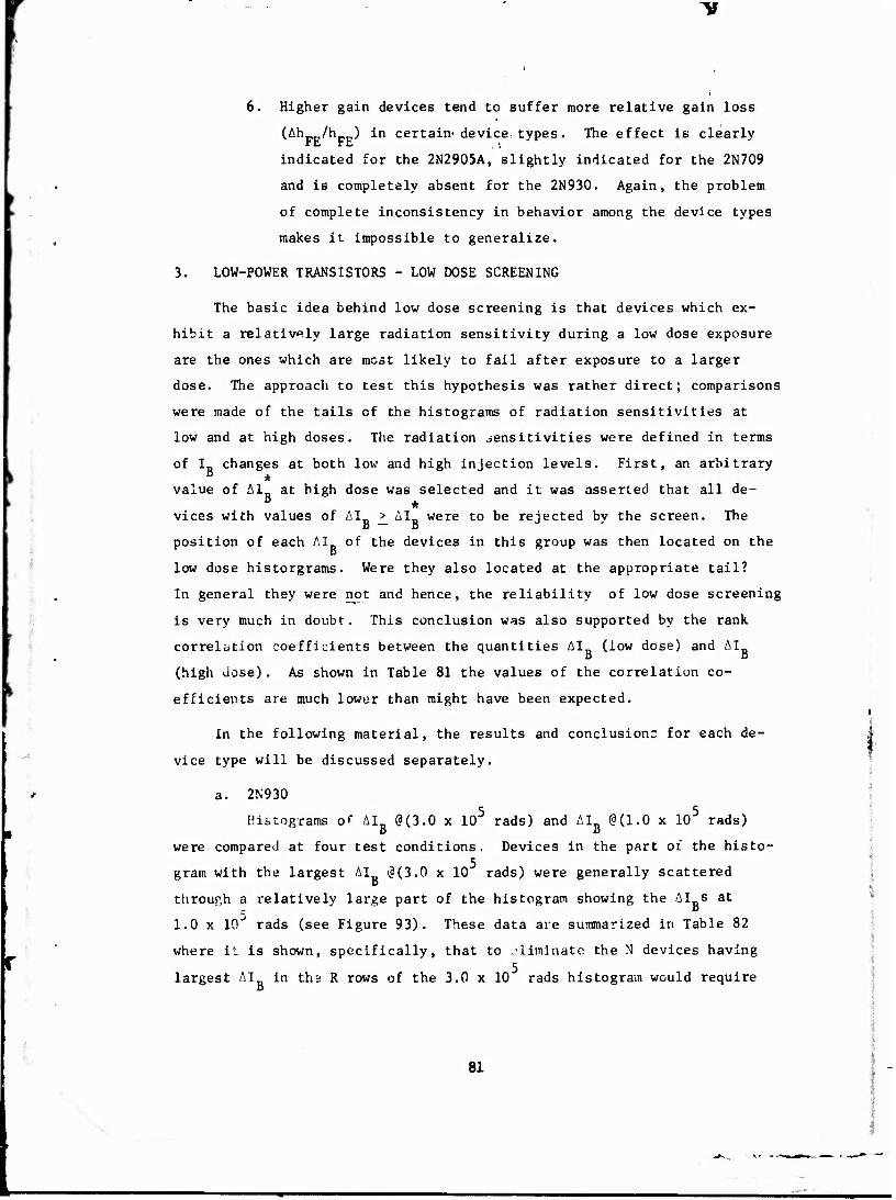
6. Higher gain devices tend to suffer more relative gain loss
(Ah /h ) in certain-device types. The effect is clearly re. rt.
indicated for the 2N2905A, slightly indicated for the 2N709
and is completely absent for the 2N930. Again, the problem
of complete inconsistency in behavior among the device types
makes it impossible to generalize.
3. LOW-POWER TRANSISTORS - LOW DOSE SCREENING
The basic idea behind low dose screening is that devices which ex-
hibit a relatively large radiation sensitivity during a low dose exposure
are the ones which are most likely to fail after exposure to a larger
dose. The approach to test this hypothesis was rather direct; comparisons
were made of the tails of the histograms of radiation sensitivities at
low and at high doses. The radiation sensitivities were defined in terms
of I changes at both low and high injection levels. First, an arbitrary ß *
value of Al at high dose was selected and it was asserted that all de- B *
vices with values of AI > AI were to be rejected by the screen. The B — B
position of each AI of the devices in this group was then located on the o
low dose historgrams. Were they also located at the appropriate tail?
In general they were not and hence, the reliability of low dose screening
is very much in doubt. This conclusion was also supported by the rank
correlation coefficients between the quantities AI (low dose) and AI a a
(high dose). As shown in Table 81 the values of the correlation co-
efficients are much lower than might have been expected. i
In the following material, the results and conclusions for each de- |
vice type will be discussed separately. 1
a. 2N930 5 5
Histograms of AI„ @(3.0 x 10 rads) and AI„ @(1.0 x 10 rads) D 15
were compared at four test conditions. Devices in the part of the histo- 5 1
gram with the largest AI (?(3.0 x 10 rads) were generally scattered | i
through a relatively large part of the histogram showing the AI s at
1.0 x lO"' rads (see Figure 93). These data are summarized in Table 82
where it is shown, specifically, that to ,'liminate the N devices having 5
largest AI in tha R rows of the 3.0 x 10 rads histogram would require D
81

screening out M devices contained in the P rows of the 1.0 x 10 rads
histogram. Both Table 82 and Figure 93 emphasize the fact that low dose
screening does not seem to be a viable technique for our 2N930 transistors.
b. 2N2905A
The data for the 2N2905A can be treated in the same fashion as
that for the preceding device type, 2N930.
To eliminate the N devices having largest Al in the R rows of 6
the 5.6 x 10 rads histogram would require screening out M devices con- r
tained in the P rows of the 1.7 x 10 rads histogram (see Figure 94 and
Table. 83). On the basis of these data, the low dose screening does not
seem to be a viable technique for our 2N2905A transistors.
c. 2N709
Histograms of Al (1.7 x 10 rads) were compared with histograms 6
of AI_ (1.3 x 10 rads) at three bias conditions, Ir = 100 uA, 10 uA, and
3 uA. In the I_ = 100 uA and 10 mA data devices in the part of the 6
1.3 x 10 rads histogram with the largest AI were found in the higher 5
tail of the lower dose (1.7 x 10 rads) histogram. The best predictability
seems to occur for the 100 pA bias condition. The results at I = 3 pA E
showed significantly poorer predictability and were more like the data
analyzed for the 2N930 and the 2N2905A. One apparent difference in the
histograms of AI for the 2N709 is that the maximum values of AI were
1.5 to 4 times the mean, whereas for-the 2N930 and 2N2905A device types
the large values of AI were typically only 20% to 50% greater than the
mean. In other words, the coefficient of variation for the 2N709 distri-
bution was much larger for the 2N709 than for the other device types.
Table 84 summarizes the capability to eliminate the N devices in the R
rows of largest AI_ in the 1.3 x 10 rads histogram by screening out P 5 rows containing M devices in the 1.7 x 10 rads histogram. Figure 95
shows an example of the procedure used in the analysis. As seen in this
figure and in Table 84, the low dose screening does not seem to be a
viable technique for our 2N709 transistors.
82

"0
A. ELECTRICAL SCREENING - yA744 OPERATIONAL AMPLIFIER
The problems of predicting total dose damage for the pA744 opera-
tional amplifiers are in many ways similar to those encountered with the
bipolar transistors. The most sensitive parameters of an op amp in a
totai dose environment are the input bias currents which are simply the
base currents of the input transistors. It is important to note, hew-
ever, that the radiation induced increase in I is somewhat reduced, one
might say partially compensated, by the constant emitter current biasing
circuit.
The rationale behind the selection of the primary correlation para-
meters, the bias currents, was discussed in Paragraph 4-b, Section V,
Volume 1 in some detail and will not be repeated again . The radiation
sensitivity is defined by the absolute or relative changes in the bias
currents, similar to the procedure used for bipolar transistors.
The uA744 op amp exhibited a "medium" radiation sensitivitv in I- a
during total dose exposure. Although not very high it was by no means
negligible! (It should be noted that the op amps were irradiated at bias
voltages of +15V and -5V respectively in order to maximize the reverse
biases across the junctions during exposure.) The initial base current,
I distribution is illustrated in Figure 96, and the effects of the radia- B tion are shown in the AI and the I,, histograms in Figures 97 and 98.
B a The data emphasizes one very important message. The use of a failure
level definition of ID > 750 uA essentially a Honeywell specification will B - 5
reject 6%, 17% and 21% of the op amps after doses of 2.7 x 10 rads,
1.3 x 10 rads and 5.6 :< 10 rads, respectively.
Table 85 shows the rank correlation coefficients between the various
initial parameters (noise and others related to I„) and the radiation
sensitivities of the op amps. As seen, there is a definite hint of cor-
relation between the relative changes in the bias currents and the initial
parameters. However, the values of the coefficients (<. 0.J5) are not high
enough to have any statistical significance for screening purposes.
:■
83

1
5. LOW DOSE SCREENING - uA744 OPERATIONAL AMPLIFIER
The approach to test the applicability to the uA744 of the basic
premise of the low dose screening, "devices exhibiting high radiation
sensitivity at low dose are the ones most likely to fail at high dose"
was the same as presented" for bipolar transistors. Namely, the tails of
the histograms of the "radiation sensitivity" (measured by the change in
the bias current, I ) at low and high doses were compared to determine if
the devices maintained their relative positions in the two histograms.
As for the bipolars, the simple approach to low dose screening did not
work. Too many devices would have had to be eliminated after the low
dose test in order to make sure that those few exhibiting excessively
high radiation sensitivity at the high doses were indeed removed. This
conclusion is further supported by the following poor rank correlation
value between low and high dose radiation sensitivities.
Correlation Low Dose Sensitivity High Dose Sensitivity Coefficient
iID(2.7 x 10⁵ rads) -I°] [£„(5.6 x 10⁶ rads) -I°] 0.629
D D D a
After eliminating from consideration all devices with poor or suspect
data we found that those devices in the 5 rows of the histogram corres-
ponding to the largest values of AI at 5.6 x 10 rads were scattered al- B 5
most randomly through 15 rows of the highest AI s in the 2.7 x 10 rads
histogram. Precisely, to screen out the N devices in the highest R rows
of the 5.6 x 10 rads histogram requires elimination of the highest P
rows containing M devices in the 2.7 x 10 rads histogram. The results
are summarized in Table 86. Again, the conclusion is the same as for
the bipolar transistors i.e., the low dose screening did not seem to be
a viable technique, for our yA744 op amps.
84

T*
i
O
z «s
to
—i
CO C O
o •rl •P « ■H T>
Pi
< m o
z rt •o H 01 §
Pa o <u n X CT* •u z es
o
CO u V 01 3
3 60 •H ft.
oaiu/aiq Nivo aAiiviaa
85

"V
>o HI »
< o
1 m a ■J- y-i 1 f- -o r. IP i 1 «-• O «- .T ' ■J i
r-- -!■ *1 in IT in tf> * 1 u «** -* 1*1 *- r- •f -* f*l i
tfl */■■ i«' J-- a> I rsj U* in r rr <0 1 «1 .■»1 U <: -- . «■- in to n in \T. » JJ O wir <r *•>. fM i'» tit fcH j> * »r >.. 1
fi «i a- "j «» O CJ .»■
i/. IT n * LI iP <N T o <l .">
*4f- n •J ü i' p- *1 «n if» 4 ^ -j ^ i.i r*- P» f- '■- .j
4 n 1/ T> ^ «" V i/' <i J »» -j J-! J **J r- i*i * <!■ 03 in
iT* tf\ «* -t r j ■; J> L'^
in •r * a> IT -T) >r V a- 3' n in «n J\ 42 CJ
m tr *» < # 4 •T U1 J> in .n •-• o ■r U •+> o r\i » > O O <*■> ■0 ^ Ul ft /) t1' j •N .j
IT ■.'» *» •T -j r * J ■r. r- o ? u . 4V *■ ■J- M 7 - 4< 1.1 m cr .jn o ■*. o •T 4' n" ift ■J <■ f- r-. ■t ■'
m •* -» * .» •* ■t J f J- ^ ir v« t **j « »■- <", Ui :< «\j -,
o« T- r J n 1— -t ■J •J * «r« ."» s ■" m * * t J J J 4 ■j -* ■J 4 -» •• r ^
- -J 1/^ *-
O OOOOonÖQ.1 7» o f ■ o O O C «"» r> C.i r o c J « -r j r
i i i i i
: r-i -4 ■ J J VT'
O CJ I I
-.11 UJ
O O O O1 O t\ O O O -O Ci <3 ^ iT NN
O O " n o o n 9 O '.: 'j ^. a rf> C O "
' ^ -i■*) O O 0£<
- O '> fv V» O -O O O
o o r» O O O ' • w «a *i * ^ ♦ i
< 3.
CO
n
m u
M u •H • •> 4J to •H •a > a> •H u «J T+O
CO o C H V c« X
C in
O CM •H • iJ .H TO •H II •a
5 to o
a) Q x: v^/
*J
(fl c u
•H « in
c TO o 2: i-t u u TO c
21 TO <u > IH
MJ <U •H X! O w
«H ex 0 c
B TO 0 M u *J (0
S8 I M U 1 H
« s M ^ [ < o
r>« » «H a 1 O tsi
( g 9) TO JC
1 t-l 4-1 00
1 o tic 1 « C j CO o 1 1 1 t
31 1 1 1
• 00
1 ^ r>- 1 f-J
ai C 3 60
•H b

- I
J y-> if J\ iT.
ifi if» IP ■ <P K T . en — * • f i/\ >f\ i/\ •
r*» O V* *' tf« * +< O * r> & W in 4 ^ »'[UN -« T> CD IT -t 4 fVJ fl 17" O <P * »r -r «*
f -t * r» - O * *' ■% to 4 ■* 4 O 0- ■* - t> IT -*i K :ir 4' *
•* < U-. "» •» h~ f> n» rg £ # i/. rfv »'■ IT
^»«)f\JC T rt I" >I ' <; <; — r- -■ -u a f '
4 •» »f «* * 'J^ u- "T» -' j -J O — O 3.» OC i.T <M J i o r> y
4 NT r <t :
\THT\ 4 + -? 4 4? -f 4 4 4 •? 4 **f
f- rj rr O r*> « o •» Pin IT ,* X m lA J r* in 4 IT J- u\ it
O O O O C O *■* -< f>l -i C lOflOf. C» O O O O O O ri r.' O O •■* —< -* • « -* -* -< ~» -' -• -* ~«
■P r\, o -o *"> O C* <7 *D •"• iACP -• 4 r- ^ n* n |i u n o UA A ir> u rj rt n iv K ^ ' if" '
<l «i n", N "J H T 4 o* O >■« *-t ' J M '•*■< "' 4 • I I t I I I I 1
O it O O O O O O O O X r*\ O U * f- *
U(^oOOOOOOOOMf-^-a;^*0-
in j' -u *c r-
) u in *_J UJ ui u; tu i en f^ 7 J 5 <t O
> 6 o o o a o o *y o -•
r»-\ if\ 0 »-«**- f" f» lJ 0- 91 O fl 01 Ü T O O >T 1" O O
v <fi n in « -f j T> m O O w O O O Ci O O O Q O
.^ IT —i o *M —• t* ^-* r> o ^4 -'i c o
3.
Oi II a)
*J •a •H « CO u c aivo w o
1-1 c o X
•H 4J IA OJ {SI
T3 rH
a 01 4) ^ 0) *J 0
a c v^
1-!
CO Ci ^ o <u
•H IM 4J n) «0 s
•H u 4J B) c > 0) u 01 01
J3 >t-( U M-l
•H 60Q C
•r-l *U U 0 « h (0 4J M «) 0 3 4-1
r-l to iH •H M 10
O «!fl H M *N^ H m M o\
o «H l>- o z
r-l
s 1) (0 J2 M 4J M 0 60 4J G 0) O
SI
r-.
0) n 3 60
87

^
.-I >o l
-• I . re, t
O (V'
at -o |
UJ u.
of ^ I UJ W t a u i
I ? At o -» lt\ lA
■ .» * » IMAI ;»«• in r> i in to * « IM . </\ "> ■ ift J\ - •4 <D f tf\ PJ f l|\ i/\ t
■JT PJ ',
f.4 a I *Tt •* •
JJ »Ui i i/\ irt -a ■
P- r- BJ tT r « w* w u> ■
iM *• u\ u* . m j » -»
-» ^ # •* * * 4 •)
_• "i * ^ <M * t/> if ii>
? IT. .-^ * 3 in .4 -t
U' "I * 3 ^ tf- -4 •> Ml ^ J>
J «*■ J —'
f -J> t JP
* P- m tf>
m 4/ O f- ^ <M --• -r
H ?' t' IM< r> o o o ,c »n »A »r> iT «A P- *J * / »4 O UP»* ip w* «r* t u"\ •-»US 4J P- o p- a «j* r o * r <# * »n O Kt .f> J* <*» c-excp «r *■ «r ■* #
(.1 p- r r- «i ' * •* ■» t t ■ —* PJ <i 1) J i « >P <• * * ■ r ■* ■* <? * ■
■ 'P. x
# <t 4 * -T >T *
?T* PJ PJ Pj »P INI PJ Pi PJ ■-* «-•"->-*-*.-* ~l »-I #•■ ~l -4 -*-*■-«•■*'■-• «-*•■'•.-• -I -.1 •-*••-« ^.-«-«.MW-t.M^*
IOOOOOOOOOOOOOOOO^OOOOOCOOOOOOOOOOOOOO i i i i i i i i i i i i I I r i t i I I i i I I t * I i f ■
UJ U' U U' l.j MJ U< J' LJ IU «j IJü UJ III UJ UJ UJ J! U UJ UJ Ul UI UJ Ul UJ lj> 1) UJ Ul tJ! Jj UJ UJ iL L: UI U: UJ •M a.- «J- I> ■# V *V J"i O p. P* O .f *»- C.l «I P -« -r *- .-i «*«•-•■* T •-« »p. «■*■* in V ^* i/^ 0 PJ IP T PJ P- 1 O ** C ^ <•• < M >r C 9 M <" /■ in 'j .'A IT. *- 'S PJ •* ■ ♦* "• -* t © OD ^ "H jp. «r o ri ui r- T PJ
« 4f PJ Pj PJ ^- P- 1 I ! (
oOoooooat *OT«.
OOOOOOOpOOP-Mf i^f-.s*jfr*»*p-jnjp-p- /j/MVPiwMO-t'no^coo'jio
pOooooo'i<HO«"nr6o-iir<i'tii'n^j!fK'fl^rtitnMfloft(^oo(
1-1 CO CO •o c cfl eu U
C/) vO
c o o M
■H JJ X «e
■H lO •a CM ca • Oi i-J
a» II J3 JJ 01
CO C o i-l p ^^ c f) CO
•H ^ JJ tl cd IH
■H CO M » CO > 4-1
C
J2 2 4J V
14-1
60 «w C •H
•H Q JJ CO <M n O «J
3 CO
U iH 0 i-l 4-1 M CO
•H Oca ss
J= M "»^ H b. too»
43 O 1^
<u a o O CM ■<
3.
1 4) J3 O u W O
t>0 i-l O 60 JJ C II CO O
•H IMW
• o oo <D I-l 3 50
88

■«
i .£ i c O
» p- ■*> ■ 0 *Ti If f IB .USi lA •
•H r- .* 3 f •I I «'V ^ I US ,|\ if- 'P - «D "V » T- ' i*t *■ sf n Ji U, Ji «i - O ^ «i -* f f. C ■* "' •P. 4% at ■/• iP r- -c -■■ rj o <M »-« ■ «■» tt\ «' w» ■ P- -v O -4J I
•A O f u . i -a C# C1 O- ' m m if N.t tn »■ * h- i -* D O JJ ' IP •? m j
a* ..-*: (*-■ si ,f. -C O -t J TJ , IT. .1 ■. *■ -f * r- o r^ s v
IP. 4 -# -f *» «\j -r> -t c* * o CP -f -y r if -t t * 4
.-* ,• fM ,f ^J
•I -r
i j
■i r ■; u tj
iv Kj p.] -M -v «•■! «inKi O t» O "-- O O a O f» ' I I I < I t I I I
r- .# n o *» T -« *i . ■* *k fft ^ W *■■< ~« * - i | i t i t i i
C". o o o o o O O C
o o o o o o -> o .
o e» n o c» -) o ^ -
o o '? • i •
■ r,i ^ n, <t* n\ r" ,'J 4} V ' 0 O *> <> 15 ■*> S> •£> O <? O C> a
I O •-« t O ■•• O C *' —* -O ■•*« O Ö O
r o fu n '> N r< *5 •■< N O ^ n '
•H II
<3 0) 0)
a> s JC ^* u
0) c »J
•H 4)
c « o S
•H 4-1 u « c
■H V n u rt (!) £.» «4-1
w •H .G C) 4J
H-4 6C o C
4-> S2 «0 o n 4J *J to
3 •H 91
.-t S M
H U
M ON ^-^i *»» O <: «r^ 3. i-i fe < fvl o
o 11 iH
/—* 4J II w fnöO u
.c G 0
l-l
rH 1 U1 «a ■n
m rt M-l <u i-l o •H
4JvO
1 •H o > rA
n •H 00 4J X 0 •H 4-1 U) u-i (6 d CM
•rt <u • SC w r-l
00
60 •rl
89

^
60 C o 4~ < 41
w
o
• « > o w I O IM
o5 (
oo fM -«1 o o
O ru in * .-t <M o o o f^l **- *
(«IHN o o o o- * +i IN f< -*
o o o m I-NJ if >
o c»
a- *> <j -* r j> i^ c* 3« (SI ^ o O ■3"' rj V» O .1 IT cr J> rsj «".' CJ <.j o
p- ^v 'j fSI J r .t
1A 7 c ir f i f\l <-« O o ') o 0>> »Ti *> a a» »fi w ^ 0" <r r^- *•> "y
o o D cr ■.J o> •r; ■f « <»• -3 IP J) sC <-4 O '1 r- 7» 9 -1 K /l r-
*n T o i/* o ■■* <_» o u n «J T ^* k* -^ <-l ■ > r* V J f- J r- O r> ■ ) ■i o *-> t_> *-■ u r*-
nf\ T rr
-^ j <*1 ri n " O I o
~>J -v» r- f .r* V
o o o O O o D O
UJ UJ li' ÜJ U' ■*» r- ir> fv u^ * «A *». ■* -'
UJ UJ MI UJ UJ 'j ; JA (J «*. f- -n T •
, j r* » h- ,-, r .
I N (\i ffi * j> u f
O ^
H OC X ■» ■» CI O O O .-«.-« -<
> o o o *•« «-< -«
--)ooo©oor>:j ' "i p o o <*» o o o o a o a o o r» i i i i T i i i I i T t i I i i i I t i J i ( i
L> Ui I.IUIUI UJ tn'iJi t- <v -j. u.' OJ a ii'u. ii' JIU UJ u' ut u, ».')■> a1 f- o <f> >r *t A «j H (j j- n N a i/'. ^ "■ M H M o »1 c N *> I 'l* i *■ T L* O H '.V M « * .r *} f* T ft- O •-• M
«f*i-.^„HnjM(\j(vjNWivji j ^ ir\ r
o o o o o looo o
o o o o o c> p- t> • * j o o -J * r- ,- u; TI .o r- o N o o o o o o o«
0 C 'T tNOOOOOC'JOO»
-"> O O -1 D^Mf i m eg «|j h* ti »v ff o "^ r> *? Ci «^ O O '
0) • «• 0)
CO
c H om •H o JJ iH rt ■H X Tl
PS o • M
<u ^! n 4J
<u Ö (A
•r^ 0 o
a «^ 0
•H tf) 4J M (0 OJ
•H <*-l
VJ CD M 3 >
■J <u C
X. 01 4J M
«J O0M-I c U-l •H •H «J P CO M >*-( 4-) o V) 0 V) r-i l-l fH o M 4J
W (EM
M (fl < S >4-l >J
0 H
§ O
M o\ OOZ O CM 4-1 w a) •rl X. SB u
CM 00
ft) M 3 00
90

TJ
> O | I
' I
o o « r-g
ifg3- :
» tl O I
i <■ «V f u o t «■ H" f
< rn —i ■ ■*> c c — -J C) ! r* ~t .-« c. u ■"'•"* **■• , J) » <^ "\ ^ * - 1) £
''-I > i/> <"^ *- T" O ", *- »N . M O ——* '? U -« f-rT5 -« 'O-lfTj J'iJNÖ-t
O1" t> «■ o ""- *- r- -M i> t\j
1 r- -» "W u"> /" *■ N *» * fo r- a» <r\ u- o ^ t- *-i■ & —i
i 'J U - U '•> .' i J -• J ^i r f\j j, M r
., i i*. tu -n 3- o f- -j i. ■*■ > o © O O -* o o t '-> v.» t>
J * *J o . < ni f j N m N / j *X r- «\ -o J't-rfHIJ^t^"' r .n T T) .♦ -n
- ^-•NMO-'^ M t D j r\ o -j o >- © tr © C3 <H
'0~iOOOf>00 o © o o o o o o o o '-■ a *> o o o o o o © o o o o c.i ^ o o o i i
Ui IM UJ 1» u; IL' UJ J UJ U 1. U1 1> <1 UJ u. Ui U Ut it' UJ it -1J LU U Ji i.t U.« 1 U li I C .jl U I Ij I LU U.I if' "J «■M^ ir^cift.noi; T»'%..»w^f-G'"'"*f»u"\r-(y>.-t*( r o ii ""> *\J .j -r> **> ■"><-» r* IT. f» c ■•***** IJ r- f> j-> "■ n M * A s j Ci ^ c * t ■& +- i* T'O'Mmsj /•■ o T c* o •-« fsj 4 in ;* ^ 4* o •-* *-J
M •* m a ** " i^ t^i •It |
i ■ !
0COO0OOt>OO0-*t>-d ^ Ob MS <f ^ ^ ^ I a
-< r\j *N "4 i\ 1^ «w *»J ^ r»\ ft "■"> (*> f° w> «1 f" r^ * <*
O © O O © © O © O Q O ' ■O f r* -o * -o «•« * vT «■ /) 0 J o—* 'J o—* -< «1 o © © o a $£ o
I
li
w (U
•H 4J •H >
•H 0! U T) 1-1 cd tn ^ c a)u"> w 0
r-
c 0 X
•H 4-1 0 « •
•H CO t3 rt n tf
01 i) en
43 0 4J O
P a 0 +-1
*m CD 4-! r* M
•H 4J u G (0 (JI > H
IU <u 14-1 x: «w 4J •H
a 00 c VM
•H O 4J CO u B 4-1 0 (0 4J 3 CO
OpqM H H *^
(OO f! M n 1 0 >4-l Z \ O CM r ***^ IJ^ :.
'! M 4-1 ■i,
60 i-t ,' O 60 ? W ß I .. CO 0 ■'
•H | W EC < M
■;
ro * 00
; 0) S 3 60
91

"V
\ i 0)
• IM !
o in *- • trt »ft
Z 41
uJ 4) '
<r JJ i — * i OO i UJ O ;
i n ^ - —
o o
r * Ift o o o
flo o »A -» ~« n NIC H «M ■**» 'ft o o -» ** ~* •*• K ft' <0 h- »■ O C- <0 K P- H f J 4 M O © U -• <~» -' -•
«I f«- f» _> o o O -4 CD O T» -i tfVF- A ~4 o o o -< <0 T K O Ut .| u\ -
w» 4> *»» t- «II *t J\ (1 <* o <-> -«
fl f- Jt
o O O 1\ >& f PI a T O <"> o
t .«o I tf ft
> T O *' 3J ' ,J *_• mt ■*., ».J C oj it* M K' -O .
$• *■ c 'v N i
o o O (i U ^ u •t <4 t* sr t* -•
* -* ^j r^
*- <j- ^ 3 ~
o o o o o
) -■> c o o -« A J t\j C' <?•
«i . IT. -* •* -T -T
O f** rJ <-> f) o S " \ T "I O i-< rsi —< -^ .-4 "•> O O o o o o
> <> O f-, o o o c» o o o o o o■ * joooooof'OOoorw
a UP.
0
tc at
^ lM u
-0 it
u ii' r^ o
vt 1 1.'
r t -0
.u
r\i "j
'IS ft 13
J b
(M
U-
rn ■J
UJ Jl .'i J
•LJ
r- a' o -,.. _. ** r *« -« «M A- 'M ■*# fv fy ,J
rj f\J m rt r« n r^ n' m l"i ■•> 4 't 1
>» > * •* * 1
"' oC o o O O O o O O f- ■J -J -u < - * - r- 4 X fli i/\ - r4 1 - r- - O f- *, O Cl o o o o o
! I ' 1 oo^>^oooor'j«-l^'M-<0'n*-*n'f- T-AO^ ^>*^*^)**'>^^ooo'^o'io
I I ■»
« CO c -a 4) a W u ÖT1 o o
1-1 rH 4J cd X i-( *d o S •
<u II X! u ai
CO a o •ri P
c o 0)
■H w U at CO i»-t •H CO H S tfl > 4J
c 01 01
X. »4 u 0)
«w 60 «w n -H
•H o 4J CO <« K o
4-1 en ca 3 u
rH o
OO)
es * U ^ H
W WD
Ji cn o\
>*H ?5 O eg
^N
15 1 Wl 4J 00 i-i O 00 u G H <n o
SB -9 [xl
• 00
2 3 00
92

"V
5 I
S3
m rf\ a) F4 1 f^ o o o o F t o w ^ n O O <"•■ f\* rj m if, j .ft T *"1 *i r- O o <*J ' > -< O •M »: </> r- f- t- ' * trs ,$ ui i/i M T *• c; C< ** o n n .0 > ^f o n r- u r- T> •r. o fM r\ \r< j- i o 1- ■o O .0 O c* M -J o i/\ P* Ti ■M fT r f« tpi (.- "■» n rg *> ■T •J f« . n J r.-' "!' •r X C J> y VJ u O < > -' o * ... ') J ■■ r , -* ae Ti a U if f- -\J <% r.j r*l pi r c" V :.N ■j n- Otf'H o o • J (. > u ti *..- O .■* IT*. U O Ü" "^ -* r- <-J -J ff t r\* u »4 <\| *Nj f^ J- C> . u-. -r « t, ii1 K. o o —t —« (. -* . , _-. o ") '.i — O O O oj cr t> r- ^ T ■*" t *i T »J n "1
r ^ 3 ' r r n ■n * -o OO o O -* -« : o o '' '■ o O O '">
•> -f i+i m I* *i i< ,i: I-' rt *i », «i *i .TI (fl «\ «\ M in (^ '^ ^i i; r\; iV rvj "M i\) («j f, rvj f\j fVJ M oj \- v N o <~» o 7» o ^ o o o c o '' o o o o rj o o o o o 2 o *"> o t j n c *~> c > o *"> o r» o o o <^ I I I . I I 1 I t I t I I I I ( t 1 I I 1 1 I I I I I I I I I ( I I t I t I I
> ^J -4 T t>- t NJ - . -- ,■> ftl o V r -1 -4 > f^ .1 ■vj 'J r>i ■»- « r —. .') r o if* 7 J- ri -T iT ■n » 'i
Ifl ro -' l~i o --1 '■> ir T •* J1 > ■" i^ '"■ *' (^ f\l '- *' *^ '1 ' ' .-
-■' ■'■' iM •1 •^ * -J » ^ r> J- X> r- ^ 01
r< "* - »N. "J m »i «1 ^ -J »" .A ■0 •a r~ r- ai 1J V' tr - -• -' -* ** ** ^ - - - •r* 1
^ " -" .. ^ ** -*
c- -5 o - n o o o o o o - f- 0? E ■- r~ J - j r- r- H Ti - t*- ■f O O f- o o " o C o o o O
"i O o ' O O f- . ^ -t r- -T i> ^ ' ''»(^-*ooooo'^o•^,^
-T» o r-l
« c o o
•H • 4J !*1
<d •H 1
CO 0) « CO
0 a> a x, ^> 4J
CO Ö n
•H Cl> «H
0 CO C) S
T^
■J *J
5 C ,H 4) >-i t-i CO <U > »4-1
U-l 0) -w x: Q 4J
««-1
60 O C
i-t CO u u « o H 4J 4J CO CO -H 3 B)
rH TO H U
H U
M o -^ ro
CQT> H Z O CM
II (11 x:
^N *J w (K 60
XI C
Öl < <3 a
CO m a) M O -H
4-1 n 8-5! w i-i -H M 6C U O Tt • M
4J « «) W C •o •H a) CO EC W u
m 00
01 u 3 60
■H fc
93

r
> o
Z1 UJ
UJ CC
m so
' I
0> a> < tf» if» <
o in t if* v\ f
> «N UA
i * t> » d i» J
fi rg i^ 1)
* (Si *
■* o o <•> ««1 »n
ff rsi «
& ■€ ■> •I* O 1 M "1 «
« IT V- '.1 T i, C> »Tt ■r n i
•H 4- (^ tf o tf>
:1 V .
<*■ Pi m T M { <o .-r o ~« » c
IM ■** rO ■*! CM " 4 ri u- f- tr> ~« -* .P r ifl T N or » T •* r~ ' in (M tt rvi <\i ,-vj "• IM f
) a Q . i^4 •
<-j rj ' O r- • * -J i i-J '""J
■ m
<J -*J N W 'i r *l -r. 4 »0« fM I^J M (M 1*1 *T '« -4J ,* r-, t|*. a-. oj (*■' f\j c* «,.„.> Of r«! «i ^ -j> r <\tfsi *M *■!
,f J* n r- i/\ -O l -j (fl ». N »I I .\ N N N -4
I CO I
o o O O i I I I I
U- Ul LI. 'Jl ' r- % r» w r- r- jj o ■
O r> C> O O O t"? O O O O ' t■ o■ o o o e TOOO fh. *k. pi.
mooooo f- *- a a- r> ■
'Jl l'. U. JJ 11J UJ t-i 'JJ i.i ■ -** *- <N h- -\j ^- *s.i i/i -j> i ><-| M f\| -4 - t 'J * J *l -^
o o o o o *- o K 4 ■ r» +■ ■* o •» a oo: »* v ji ■ ••* -« a m * o■■*•-. tn %r c- 4 o O ■# o © o f- 6 o
'3 O O O O n C C »* O O - if i ifl cj h- C n i\| f- in J N /\ J in rt o ^ o p w O O O O'.i ' '■
'»OO^O-^O«^*^* • IMT* *0 i»1M*'Ci 1 •"■> .1 -"> - * o o
(0
•H (0
•H CO > M
MA •H o !ft I-l c 0) X
CO ^D
£ • 0 m
T-t u H (0 H 01
13 w 5 o
o >-•
HI Ä 0) u M
m C IM
TH CO 3:
C 0 4-J
■H C u 0) CO h
•r< 0) H 'i-l t8 0-1 > •H
Ö (U Ä U-l W 0
or CO c h T-l o 4J u 10 CO u •H u to to 3 §
■H Wi iH H H <
pom H O <l CTl
CM IH a o <M ^*» I 0) <
Ä 3 M w oo C1 o be 4J C II tn o •H 1 MW rc
vC 00
a) t-i 3 HO
94
^^U

> o t
O I Z I < a. |
o * o o f\| -1,
r (* (\ "VJ
■# «J * o <r x» (T. f. "J
1 (M «V t- » <n (*-, r
j f, Ji •*■* J> * , r>i n Ki ft
s o r- ■<> -!
^ *n «^ 'i* >*%
- C -O C T> 4 *M •* "* t
j nj j M (t. tfl i
4 'V - > *-< *\ -T ;*J r>-
> .( r\t r-i T> r-
tj» C* o "iJ rj -
t- .-* C ip f ajcc i/ r- <v ■ fsl ro *g r-i ", '
!/> r o :f J"1
* j- r -< '■> .
<\J f\J <M • J ^J I
•9 -, -U *>
> rj o o o f, c> ^ ■ o c '* o O ("■ r:
U' U' '.'J '- rC O t» -* "* ■ ■ *! T r< *1 »T' •*■
-T lT\ ■!> "ft f- '"■ ' i -M .J /' X U -' -* O -\
o t> l a D o o o ."> o ■■•■■• * *' ■* o ?> 4> J> *
o -■•• o o o o M o o oooono
>jj UJ Ul r- r- n r (7 *<
U> ti» '11 ü-l U' w T C- O n - - ■*N u" t CM-»
f> p» t* a> o T' (?■ n» tK
1 o o ■?> o o c- tJ O O
O CJ ''-' OOOlHiO
o <t> o a o ci ■ «,i ^ ■:• T 3 c% h T - ■* "3 • ( o -< n ■ >'
. (0 (U •H 4J •« •H 0J > T3 •H « 4J M •H (DvO c o V i-l V)
X c o \o
•H • w to « •H II "O
PS (A 0
<U P J2 "«-' V)
CO c ^
■H a) >M
c <o O 3
•H *J tJ
si c •H 0) M M CD 0)
»■ > IM < «n t *J -H r? 3° — *■< .A «»-( X 00 o
e 'V •H M)
1 i- 4J J-l i . m o ' a. M 4J j *J Cffl 1 u;
if 3 (0 ■ <
T-i W ! U
UJ M h X H
! - o pa ' UJ M <; . -j »«« IT) 1 l/V POD »-- M W i = CM I o «w Z 1 Ul O es 1 * ^-v , <
g a» < 8 J3 3. —
L« . s- « ■7- 00 f» '—* o 0 M
> °u ß d "> a o o3S < H
"joo o
00
95 ? I

[
h- ■ 5/1 f*
O — U.' -•
> I < I X I m i
I
. i
f ,0
•4 CO tn * if»
tn *> o .> * *■ * ■*
<M rj rj «V m «-> *» r- * *>* M* ■» INt /Ni *M <M C p*. r^ si \r\ *> If» «' ^ U"N (MM «M N m ^rjOl- a cm» * « -o *S» f\J CM O* f\J
fin n\ t\i »> -4 M M N M N * f» if» f* r»
W N M N N
* IT« *. ft
If» T» ^ *\ ■* <
^■i T« -j (M *»l 1*1 MI <i F>
«i -A; tn r- y\ (M
'H •* * O * X PJ *J *l Al * ft <\J -I -t
,r ,- -J m -H i-i «i -*\ .«■». ri .f T C IM K rt
i o o t (*1 c">
I OJ fS* fsj f-; *1 « IM
t I If» » 1
l_|L»4.»«.~l.-4«.>-4.-< oooooooooooco 3 o O O o ■ o r*oor)'-»oooooooooooor>t>'-> t I I 1 I •
_ IIJ ill ■ < o «> *, > * if n i
i i i i i i t . j UJ UJ JJ I*I it» i|i u: ■ r- tn ■♦ M -> '» T> >o
.n /» r- i) '* **> '.» -«
l l I t I I I l J UJ !li IN Ui UJ UJ U 'U UJ
K. *r* ^ oj -» > r* •4 *y *» ^ m m *>
UI "J a. u
1 | I t * o tn m * u-» o o « h- *■ o »L « OGOOO^OOOf- 0«-«-^-T'm-HPgrt)if\. - o c» o o o <t> o
OOOOOOO'pOOON** « <f N 01 N "(
I O 'J o o o o o qt O - O f>
-: ir* o M « m IT« iA^iOot">OOC»OOOCt)
■'■ O O J> O 1* -t »*> ♦• *- A* * ^ «> »I- *- ^ < o i p o o <r» o I " I ■»
lit'
Ö o
•H «
Id 4) ■H M-4 T3 «0
A <u c
J3 (U
ai •H »W
•H C Q o w o «9
•H ID h U <a o > 4J
A (0 ws u < M O 4J a» u n CM 3 55 W HNH
WS)'« .C 01
o« ^ CM M
J3 ß
O
«M 0) O "H vO
4J •
it" o -H a) w «o » •H o> a
ao ao
s 3,
•H
96
* ■- >Jt MMM

f
o ü>
> Z Mi I
»ft if* :l
o a » if» ■# ■
i*t c\ ' MT fi * mcir -I IM C ■*■<»»-
m m r
m m <■ -t O u
., mt» <■ m t-*t n# r
■4 ix ^ M A.I <SJ
O ff <B « r-t — Al f\| flrf f\ «1 (*!
►- f»
4} fX u
if« V si «M r- .
. tn ii »■• *r *
•5 J O if
n a- n *t ■*\ ''i r^ '..' i'i ■»> 4- n-, st ~ -' "*■ •* O ifi ',/• X O " - P» *>J (M (M 'M l\ i* ", O f - O f- .0 *
W iiM*i. i». t, "•*» ■*!■*■ i"0 -^ rf, •*> f*. "i *^ *\ ci ifl m ff1 'i i*j (<i "' (•■. ,*■ o ■"> o o o o o n o o -o o ri o • > o *v* o r> o o o o ~» ft *> i l i i i t i i i i i . i i i i t i t • i i i • i l i i t i i
-. 0 ^ r» -j r-. j ■j -i -i m a- st -• «A ( n n ■JJ -i -n f\j r- ;; f~ »i -^ T> -** o -t o Lf\ 6 r _. " t
•o "" th f» is. ■"* ■i> 0 T> j- -J '■*■ 1 r- ». n •-' "•' ■*, if- 0 T T -' •NJ
A •*■ '■
G — f\ r r X -1 "J o
X * ■i ifi <*' ir> i/> r» iTi *r* ■D «o *> U -»> .n f» r- rs. r».
1 r- f^ f- 9 CO ■4 ■c -c U tT1 (> (T vr c> cr ■> - -"
o oo r- O O » + r- r» O -* m r- u> If - r«' «t i, \i\ cn h- O aj IA - -» - f>- X
1 6 -r o o o o oo
O O O O O O -* ■■•* O O O ■-* *M >f 'J X f ■ J- «J- ^ f. r- IT .' N rf^ <M -i M ü r, (J) M O 1' O O T
ft. O O r-i '1 O M Al fi H O M i J M ft( |n * «ö *• >A »4 X r* «i f* *•"» rsj fTi v4 sj O M O O O O O O
! -J.
c o •H *J «
•H •O
5 V x: tfl 4J u n »4-1
vt
c o 4J
•H c 4J a) « C •H D l-l M-l 1« «4-1
> Q
a) Ä 14-1
4J o 00 tfl C u
•H 0 4J 4-1 cfl »1 U •H u tfl (0 3 8
1-t u *-s 1-1 l-l
< 1 um ro n O ^^ a> II
ms M •z W < cs H
II Hi • M
Ä tfl *^N 4J •a K «A (14 DO u j: c **^ OsO
1 o <
Ul X IH 0) o •H
4-1 vO
1 •H >
U1
t-l •i-l II 60 4-1 o •H 0)
4-1 tfl tfl tn c 0
•H (U o BC w N-^
o\ 00
ID U 3 60
97

o o o *
o o.
— o* • •M
O I u I
I I I I
• -< 1 > O I tu I O u. i
I» I • • I
OK I ►- • I l/KM I
ui «• I
• I
o a) ui m
> a o — i
£4
o o*
o at
i I '
ft ft ft
*0 — «N
•*> I<^ *•* lAi«f Aj
m **> IM K O -« ■* *t> \f\ *\ r* m m *** ft
! 5
4MMÄ
» C *• X o * IM m in
9* m *■< < o- *
rg IM ^ < O « I
IM (M m I
*VfM i i**!l*l I f» O > IM OO I it IM i u> to t
INM
' g? w »
I« >i < I Of" < I J51* I 'NN< I O^t . I tA * 1 I IM IV • CIO > (M * I IM IM
» f* l-tf ' *— I*. t IV *M , ITS f* I o-o I IM,IM
4 IM
fg I
O tl> IM
IM It *M irt t/N CD g I- 01
MMN O fl* IM o vt «* IM IM IM
« * IM
f. -I * »- *,f» IM IM I o tnl r» rt'i IM N|IM «* IM'* ■o n-.-e IM IM;IM m to * «IM Mt IM«M IM IM* * «O IM,* IM IM IM -*ft I* ■n IM!* IM IM*M 0. ff. OT. « »i.in IM IM I'M tft 40,0 h- — -"" « M IM IM »M — «'* <0 MHM«
IM IM IM IM 4 Of- IM O —fM •« IM IM IM IM * 00'IM IM O O IM * IM IM IM IM
IMfMlMrgiMIMIMIMIMIMrMIMrglM^MIM'CglMfM'lMIMIMgM 00'OOOOOOIOOOOOCOOOOOOOOOOOOOOOoOO;0 00000|(
tf Ui UltJUi'ujttllJw UUU.UitLlb'U'UtU.lJUJUjUJUituU.UUJlJUJUJU |i> kü U U.' UJ U. U* UJ lu. "***"• ,UMtf*CC.»*»^>0 0 M^NOViHtffOKi'Wb'iNICf O *- C"i 01 ■* *** ff, vf — P*- rt ff- -O
«-« IN
I f I ili i ! oo oooooooooo*»»
1 • 1 i ' ' 1 1 i g> K tf\ m 43 >P IM IM "> 0" O »0 O U"t O O O O "O O O O O C ,0
oo o oo O OO'O O O O f tft
1 1 i» tf\ IM -> r~ o o o — — r- I- »- IM o o o o o o o o o «. a
! "*i""" i 1 1 i 1 ÜO o o o
1 I ooöioooorvff-
I i - 1 i 1 ! 1 ' 1
«MO' <*■ «Ni <M *- '* #■ ffl-jfft -* N -•.•# C.OOQOOCQOOO
1 \ r i i
Ho
I : • !
US
0 J2 CU 4J O (0 WD 0) •ri tnx: ^i SÖ Ä U H
o
01 u 60
•H
98

ä
o o o ■*
o t
o
11 11
jl l « • I to
i !i
o
4« II ijj m i x. t~ i
t i M I
I I I I
N I O I
Z I < iu I ;— <r- i O m I i) f- I r . i I
> i • i
O I
si
tu I I
|Ui UJ I l<LU i I
<y an o o.
o o
■4M. V r-'j* AA
r» c ■* «% 00 1 *• «Nj rs* -«N it <0 iA ,4H •■* r-< —» O O
«# §*£«• O O
_ _ O Du O O . *-* m ^ t|> *\ ■* f- QLF 'SJ **> t) n ** *♦ »£
a, o o *■ -J" •* «*"* ft* *## rw Mi ^ kT A A li^ 00 if* ■* f* «Ni
.-.^W «ÜB c> c o o o <">
o «of»
- K N V-Ö -Ö -C r- ■* «N« o o o-o o 0> H O N (^ r, i
iX j- « m -- o ■* o o c o o o o c O
* —i c> r* »A et A* >\ o r>t o O O O o o o o o o o
• •
OÜiO
( IM fsi rg »oolo IUJ Lu u.
— -. (Si
rsi f« o o'o
OJ N ^ '
o o' •oooooooocoo ili/U.iUiUUiU.U'UiVUtikUJ
o o o c o 10 lA * *** 4)
o o o o o rg ^ .-i -• CJ o o o ,o o
'"C IM (v rsi *v *M < o O O O O I
o r- » r-j rg o o •» o
m -« O o o o
l fst'P* I o o
oo o • •' • 0 0|0
o o o < • • • o oo i
T o o o i
i
I^H*«NM cgfs(fs*fNjf\i'ti<Nf\l**»
U. UJ lu U U Ultx.UL.UJiu
*•% t* r\ 4*\ r»> t*\ r\ r~> •* ,-t + -** ■■*
NNNI o o o <
u. u/ui A r- "1 ry »O •#
I I :
o « ■ • ■ » • •! • •
iFiUt
o o b o ^ «■
o * o o O O '
c^^tfvir»*- rt- ft* ** «o <** !
UJUJU. -^ <-• IN* m * r- ■ • i •
.1
i
Hl IM Ä O
o
Ö
w
T3
H w
Mm 0) o
o
01 o X • u m
1 @ t! *J o «d
3 B vi HU«
O SH
■H T3 > W 0) d! In
^! Q Xi U (i T3 •
* «J 2 « M o> qrt 2j fcC es
. o • (3 •H'-J •HtJfl rt CD cö O H U
0) 00 •HMO rt U 4J
•H O t0 V O -H •H Ä Ö W H tn^-v
J3 0) 4-1 10 o to o a Bv rt M u <u w 60> tu 0 J3 4J O 10 Ei] 0)
•H fnJ3
H
60
99

o
tn -* et
O o o *
l/>
M
K • 4 O > O u
> o III OIU
t|Q<n
I I i i l l i l I Zu I
o
4 111 — * 111 * X 5
•r
v> 1 in lk
1 Sü*
s ! »» i »- ^ • a Z «< i U. UJ
5L U *w 1 u j > 1 • IK | ■o f* t z
•3
##
♦ 5«
^▼tn »A
■ MAmi£» IHo I or
, WT * » ■»
ft iff 5 0 ^ IT f ** c •sMc mCBw< #▼< •»•▼*
»■l^ ■r or o -• j ( «MB« m M *M Til •* * * <▼
^^k -0 f^ c 6- n. DB rr» fr. IM rn ^
IA m
mKn I «MiA ) -»,«1 i iA m
-W-a-\*
••!<• in in OM •» O tA IA — N O 0- lA * O l\< o in «1 ■#
9> IA >» * o -o r > 4- ■» «D IA • .*
IM * IA .«n 00 o * «4 ^ #n *MA IA -« rg • — * «* •n iA an «o ^ * O fl <M IA IA IA * e •»> H -0, a <A O -C -C IAA .«• IA * # IA »1 m in -• o *-,« * * •» ■» «A m 0> ^ * * 41 K * # lAlA lAlA
«> m n» m «n
i
oato OOlO
I tug. w 00 « «5 •> M *
oo'o ■—J '—L — L--L--L OOOOOC 3 0 0000000000000000000
(rCiMm — actAfNiCrf*- *»<(OiOriON^-ip <c »** o f- »A *% &■ . -*&,&Wtf*,**Qt<\it\tD-<i+ OCX wir f- O l« «^ ao —* -# «0 &■ *v •* 1
f
0» in
Si IA. «"I ■r
mi* an Ian
O O O O O.O O Op J U' li. If U> faJMJ ■ O IA fx w f- j- \ IA «? — m -e *
i«1«**»''-*r"«,«»iN« <r *< -* r* n* Aj '*M M i
O ^ ►• O ►■ * ■# IM I
1<«sf\r'W**,«*iAIA'lO«0^.CJ>^>-?-aDflO«OOOffff'(7'
I I I I I o r» o • ■ •
O -i o
i oe> o — —
«OK
-• O.O
OflJCOOO O IM o o o r
i "i "■ _r- i I i T o * — c o ,o
tie • -«
ll
a) <** J= o
<«-i -H T> o <d a)
C VAO «I mo 4J > rH X 0
a) 4i co
Ü «H
a) s 4J u o co cd U U fc CT» 4J i-l
iH cd l-l CJ*-v
■« o W 0 0) H
•H > w Q ^3 T3 « 01 Oi ^ O
c •
cd o «1 H <u u u o
u 60 o
■H
W
X 0) CO o O 95
3 . -
U 01 W Ö0> fa
W O « wai
CM
01 u 3 60
100
X

... ^ 3. 1
a. 0
I?
L . .
; ,i -" - A i I i i i
II •j,. _
••• - >•
03-:t fT .* V f4 IT O
34 » -
■ I , , 1 '•' f '• " i- * ' .f ;i 4 i-
l' 7 'J T
i '7 4 r- ~ i i i i ' • »
:v.:
3 J
■- - i i -i ? i i I I I » 1 - 1 •> -1 r- --} 7 .-. ? • ... -j ,_- l I t I l l l I I I t l ft l
^-3-0- O * -'■ '.r - '.' ■ ' • - - 1) " t ..--'» "JO -• ' '. .* J f if u .
> \ • r; r- 4 5 J ,.• : ■1 ;o.ij
- O * O O ■} 1
<D J2 u
a) IM , £ o u 1» ! LM c o o
•H r-t *J •H « CO 4J H . fN 1-1 CO
^ ai OS .J p. n t) tom X o 4-> a) 1-1
fl) U X V CO rt n K o 4J V4 i CO f* 9 CD
iH 0) CO i-l a o M
o o
O X. 4J CO 00
<u •H 'S o sc a) •rl M > «t
u <u o
1 p
4) CO O Q
O .J
^ I
TJ 53 • CD <S PCW v~'
u 00 o
00 4J Ü ED ■3 -rl c « 0) 0) l-l u
crt
PR
< a «t 0) t-l CO 00 o O P
CO
<D CO O P
A 00 M «
PI
cu u 00
•H
»I
.1
101

1
a. *
■n
O o O 4
5 ! ••* t i • •>
>nl o Ü
HI I I
• m i
ZU[| « * ll ttl f» .1 ■ * w
• I
• .i
,?! - O « OO 1
**!
r IU
I IV»
> t « ■
25
IA O !>• M z
I • ■
K at H uiiu •
* f
! I
«i
in N I 4 I
•n W W
♦r» «A tf» A
I
m «*>
m m i»> O «• tf> •#•40
P. V
. MN K <o e
w* •«. r*
i Ä ■o
4> >
t
»*» H|«V
in ^ r- fa i I«» rv IV fi i i« ~ • «I I o
I w lf> I Pi iNi I 4- , <> i 4) IO
i •» m
0£i «M ift I»« 1*1
•** IM BOX 4 I»
kri
4 •0 *>r-
#kuN a> <o 4 * ■Bo «n u- e o
I WWio <M iv «v *♦> ♦ «• ■« IO 'Jb« "^JV
Mfcniä«ä fn*>o»*Ci**i*- «■■■'' (4n"in »i^fN NWWIT'I N IM »V IV IN IM f **
* «■ m • o p o o r
utuuiwluu * ■>•« r- «-• «n o tr &> *T> r? *•
............ to «r> <o r «r o» * c ■ « k «r «> * n• f. K poooooooooooooop
tf> in »V ! * «X M
r»A»
•*> <r M -I J3 ■»» IV M fM r- 4) 4 -• »<fN| fM <M M
»o 4i S MM
«>*» O I»
MN en« < In I» NNN r- »N O < ♦ f M M fM « 4 B r- * * IT *■. IJ fjf'NI
•t p » r- »\ N(M«NM
I <M o
r>o o SI IV IM
I» o t # Will O 4
ooooooooo " 1 I t r) I I
lü ui in IAI UJ üi u* III Ui 0'i«lf-t\i4)&«»ff'in
IV ft
?? tu IU r~ M c o
IM *4 *4 -I H I 1 I I I
e p .o• i» "■ 1 -^ *< *4 M I I I I I
JllMHrtMH
lOOOOOOOOO • T I i I i I .1 i
i ut IU |;j 111 u: U' iu UJ ui iw3ffMlfttiPimri-i
tr IT o o o o p •• -« • i i i i i i
Ul IU III IU (L U» UJ 4 f- O »«- « N O
5 tr 4 O
I ill UJ 1 N ' CM
0)
4J 0)
O 4J
10 <M
g° •H r-l ^> *i -rl TJ rt d oi uH h •H a pvo
•H 0) O l-J &rH
O. 4) 3 X
W tlvO
0) «J iO
OOI-o'-»iO«t*<llKl
I I i.»«0r^K4>4>iAi>^« mmfsllN«rt^4 p-io
» I ,1 I I
ODlvO>INN|i4KI«ll\r^N|tMP'4t'nf< 'ONOiil
i ! i *• m ~ i« •
I I I I ,1 I I I I I ,1 I I I I
i^o»ifiM*i^r-oooooh»i~
i p o o OOOOinOpo
i o o -» «()n(iiii«Niii4>i-4e'*>xopiii«H4Nli4t)|>aafi«>iio «IOMMOH<
I I r
- n
i u b
(U
§ u
I
01 CO o a
00
uns
VI
41 o « ■H < > «n fl) O
•a is » 4) CN PW *-'
r-l M <3 9) a
0) CO
o Q
I O
M 00 • o oo u a «
•H -H Ö 33 0) 0) M »4 M U <
CO
a cu U (0 oo o O Q U (0 > •H O
0) M 3 oo
01 (0 O Q
JC 00 ■H as
102

>
tt*.
r
!• >^
> u O a/
O <A ,*— •
1 i 11 i •» m
i in
i - o s
4 «J » O . 4 «u k -O
« .AI o
1» 'i U •
»4 i • *rt k V» ,i w t 4 * t- i> a
l/l ! 5 « i ■> • 4 U
«1
. 5 IM
ft , *i X < i Hi t k- ( 4.
& •*» |o i- IS
i \u «o i 4rt Ui »-
i "" !
w 1 '! o i t- • i- J z MZ IX 1 IU Ul ,1
i i Ul u > i . . Ul a Si 1
;A *-•
*\ IA .-» « •i J «A rf* r- * IA vA
«A *?*
m »A •A r> ■A tn <e\ +~» u. <n iA IA u» «.' ■* M •A f/l <#VfsJ Pi r-* «A tf> 4 4^ *• O ** «x iA tA
1<1 -■* -O ifl .-»f » »A •# .. j o »A m
*-. fi»-»<r *-i iD u> uW lA t.-> « «i <r v
IA »**^
o o tA -A
«n O .t «A
to o <4 if>
3(?- i^/ ^ w r- «-r \T ./i «-« 4 -* tf»
, m* f>J r> > v oo *-• t t •# rf» ■ 4 v ^
O O o * »f »A »»> r- »A r* CD 4> N (^ ■#**■•# tf\
O -a <T -O tf\4l h 0 %1 J- * f *A ** ** <9
to ■?*
4- in o <o f-
I«
00 IP 0 o
1 I Ui LU *> o
m BC #n
III UJUiU.
* O *
I O
-I >» -r J •* "I ° J v * •» *^ #0> I«
Of» * 4)
> OA«
to 10 0 00 o o p o III»
<U «J Ikl oi
• <•««
9. (r
t i ?? tu a«
. ... . ... . .j. . .;. lo-o«oaD«ooDr>artcpi^cgnir«f-^ 0C0O0Oo0Of>O0f)03O 4 111 I I I I I I I I i I " bj Ui Ui »J tu u: Ul iu Ji Hi I.U ui Ui ill ^HOQP>«ll-N/IP^ ♦ f" rt I idHhMliJOi'H /O*
•F
it» OK i L ' lOl-M
t* r- f- f- r* 3 O 3 O O C p
I I I i» I T ui Ui Ui u: Ui ui Ui W ?» 4 l> «I M » O O -« N 1 I" *t
r- t- K t- O o b o i i V i r ' ' Ui Ui Ui
.to* to «
»r^iA-4^rtrgf^f4-H ^Hf-.^Hfum*« ^a^-o^r-^cog-v- ^ #-««-*-* *-i^4--«ri-i^(r-i
',' • ' ? ' • F' ' i ! • I i ■ I : i r 1 NOlMn^1! •*• WO«
v> « * K
I ! r-opt-oj~»t-i-o--pocbi
OpOOOOoPOU*Omt-IA>flJ0'4riOOpOOOO3~ — Op3opOJ0O j I I ♦*--- I I I I
ipifiHQO^OMNfifiO^OonbO ip>iOii00p-<H«o^ri^rUMtNii0^ri>iob^otiN*iriO'<oonbi
I
0) u 00
103

< J > ^ i c 1
O I Z I « "• — h- < ar- i .u "t i x
ift|P«MAr»-f'*<rf*«rtl*innrtPflCvNNfyNN^»,HM^-4« - f. « f <«\ »4
at Z UJ IU a o
i i i i • i i i
O O «9O4'0i}'Of l^rv«
... 0600000i]iyO*N«(l-
! ! ► w4 ** 6 »O -4 I
I S I p f I
«* >!* r» »A i - *[> CD p «v 9-
(•AnnOi)OoöoonO
> o oo oo > > o o 6oo < >
8 •rt 4.3 «t •rl U
> «I
! u cd M U » 3
a w fl o u
o a «5
«d •rl
a n M « 60 O 00 w a a
a» n 3,
•H
10A

O I t I
Zui I < O I UN 4 X *n I
• i
o > •» • o i ° 1 ° 12 11 ■*
1 4U>4 1 — "J 1 i o<M E 1 ul tn :t
K l
O O |
-• <o o o» o*l IN I
cr CO I «M rg ■ «•« co ■ -0 r» ■ >( r* ;
lA I CO
«4 rg ^ -J B3 0- tr ? J>Ö
! £
O 'M O r-
a *» M rg fg 'SJ 4 «C 00 «1 fi o rg rg rg
o c
r» rg » ^ o D i». ri —• O rf r- eo m r> rg eg -^ .f <M rg r- ^ r- rg M ~* rg ■f» 00 •O (T -O rg —' ~«
« n x. i i> b o i O- ^ m ; h- «C % < C'J fg 'M « *-* « o ■ r*- 02 kT- rg r\. 'V • ö JT O
rg rg rg ( -•NO- sf !if\ PH • (M (MN I O «C» o ■ *-4 »f\ rg t rg fg rg t tf\ r*\ rg i O Of -« . ig IM rg '
ONO: oj rgN i or IT -• f tr o a . -« rg ~< «
rg rg «n .-< r^ t> tr> r- to rg rg &
/ CD O (O 5 gr r- r- KM^N • r- r- tn > ■*■ * <o
: ■* o «o \ ■# O <n
<•*«> i ix »A rg * rg (v N t -^ -O yO
J rg rg fg ^ r- <7> r~ j •-* f> O JrgNH
HIMO
I rg rg #-i
' o -* to
»<rr-eo.or-r-0>
_i -NJ r-< rr» (T O •-» <0 .0 r* r- O1
)OOOOC-*000©OoOOOC,OOno'300©t>OOOOOOOOOOo60 i i i i i ,i i I i I i t I i i t i i t i < • i Jf t t i t t If r • ■ ' ' "
JujUJbJiuuliJujuujiuuJUj.uuuu-uti.'iiiaiUJUJui^jiuuJUJiiriiJUJUJUJUiujiiJiuiu ■^Cl/^lfl•T■flN^-'0(^(t^■■o•cl^J"'N^•-oo••t>0!D^^o■o«^■lJoaoOHfim iff rf\ Hlf* !»*.■(> fl^N <Vi««f O O N !r ■* p *NR fl « K f * tf O 4 JB;N ^H*» «N
rg oo (r
r« *4 r< ■Or- ^ -* -* +4
t I
o p ( r'
>f- r* r- ;i i i
4 O'Ain m 4 J (f, m h pj N H i i i i i i i I I ,i I i n
i a f»
ooooobo-if'Mairii^ - i r- r- .c O N r- o
OoOOOpO^<-trgi>-r>'DX' <c H * * O O h >
o o o o o <
J--Ü i r* (M to <*> (** fr -♦
• fM^oooooooopo
fim-tMoobooMO^bo
01 0) •H AJ •H >
•H 10 c cu
CO
c o
4J
Ö o
•H 4J /—s « 10
•H T3 U n> a) u >
vD (U O
■d -H 4J
X M (3 vO
■H • 4J m (fl V4 i: 4J CO 0) 3 CD H O J Q M •>—'
pace M <X < 1 M-l P. 0 o
% cu
u 4J t)0 0 00 u a (0 o
ON
cu n 3 60
•H
105
i ii ML

i
\ • ,1
X C 1
I
I ? t I I «J tw> 'I I »- *» I l 3 « ■ I w s I
of Z Ol in a. a
i (
r J * *■■ c x r» a r>- x> r< KC.
IS. *, &<* -g r t b ~
-.»«»; : -j r» p ■
-. "i «% ■ ■ r- 'j Vi i
• CO ; =0 »
X J1
f*> rsi
r* u rv (\.
: -M
j> r-
-n o Ai tf\ ■1 f 1
»»»«or-»!
O -*
4 " -■ w" .i •* ir. f?> r»
*M <M
-I
o ; ->i » •;
j o f I A4fJf
) .-I ■*.. -v, fj a-t (*M ^4 <% f -r - o ff N ■*» **
> o i *j — t o -•
fM (g • ox , •o ^ ■
-i c <A * I *M «M ; r» 41 t + r4\ OJ *SJ <
: r- (M ■-- « J) i ■ i^ a -. f*. 0.
'-" f* f .' /■ o ■* »
) «g —t
1 i f-
1» r-j if»
3 ft O C 0OOt>OOO0OpOCC00000t:030O0030C ooooopo
UJ Hi UJ UJ U. UJ'i: 0i LU rj UJ Ijl U' VJ UJ U' u. X' ui u. U' U' JJ At JJ a» tu nj <jj UJ j; x< ui UJ JJ ui ui Ik' LU oc^MTf^ff tfN^-r»'*\oöc*kr,'^r»- omin^nr'V'-tOOc-T*'^ ■CiP'£ff'*»4ir<NS'0
i • [ i I !
V
u 00 a o 4 Ö o
u (d >
6C
at u 4J
3
<d
vO O
X
vO
m ^^ PQ
(4-1
o
H 0) t>0 O.
31 co •H P. 50 O
00
<0 U 3 00
IN«MN3AQ^HO0ON60
106
J^

Table 77
Rank Correlation Coefficients for Total Dose Damage Prediction (Overview)
X vs. Y (a) 2N709 2N930 1
2N2905A
(1/f) Noise 0,3 0.2 0.3 |
I°vs. IB(dose)(b) 0.5-0.94 0.33-C.7 0.96-0.97
i° vs. i n° (h)
B B' B • (0.6-0.4) -(0.3-0.2) 0.8-0.7
B VS' ' V e) E ' 0.2-0.65 0.2-0.4 0.0-0.7
1/1° vs. U/I°-l/IB)(b)
AT (low ir.jection) vs. :.ID (high injection)
o
Ü.91-0.94 0.97-0.8 0.98-0.96
0.96-C.55-0.2,'e:' 0.98-0.90 0.9p-0.8Ö-0.55v=/
hFEO VS- hFE (d°Se) 0.56-0.80-0.95(e) 0.36-0.49-0. bS^' 0.97-0.97
hFE0 VS- WhFE (d0S6) 0.91-0.94 0.97-0.83 0.96-0.95
!'FEO VS- hFE/hFEO -(C.6-0.4) -(0.3-0.2) -(ü.8-0.7)
hFEO VS- ihFE/hFEO 0.5-0.6 0.3-0.2 0.8-0.7
i/hFEü vS. :(i/hFE) 0.2-0.7 -(0.4-0.2) -(0.75-0.6)
.0 (c) B
-0.5 -(0.6-0.55) 0.7-0.85
To ,-.(d,.c) lB (O -0.4 -0.4 0.7-0. 8
AlD (due to \T)(c) -0.4 -0.4-0 0.75-0.8
Alu (due Lo burn-in)^c^ b
u -0.3to0.3 -(0.3-0.2)
^BO <" BVEBO> -0.4 -0.3 0.6-0.75
"EBO (T) (°r K*J -0.4 -0.3 0.6-0.75
ÄIEB0 (due t, ■"., (or ,.BVEB0) -0.4 0.2 0.6-0.7
&lrnr (duf to burn-in) to1.1 0 —
2X930 (<!■"> *°** — 0.3 Pre- T° bu™~in( (T)
-0.4
— -0.4
(a)Unless otherwise noted, the Y parameter is Radiation Sensitivity change or the relative change in the low injection Ig.
(b)All Ig values w«re taken at relatively high injection .. -el. (c)All Ig values were taken at low injection level. (d)"T" indicate? ether than room temperature. (e)These multiple entries represent variation with emitter current.
correspond to the direction of increasing current.
the
Arrows
107

0\ o 55 CM
01 C «i
CO
a o 4J tfl
■H
iS*
CO n 4J to 3
O
o
U
in
*« rs.
> n r» SO *o CM r» CO rH • rH r^ en
8 r* CO co r» IT» CM <t CM 00 ■«» CO rH
•o id u
so r» vO «o H CM CM O 1 1 I 1 I 1 i-l o o o
rH O rH
o I-H
O
X X X X X X X
so VO o SO «n • m i-l «O H 00 vO CM CO «n rH r*. 00 m • • • « • • • • • • • •
CM H co CM
•3» CM o O p rH co rH
»•« o» a\ r-. 00 o> VO O oo o» • ST co rt
(0 > r^ so si- r*. m CM «* !-l Ul so >* CM •o o tt u
oo f* m N CM CM sQ I ! 1 1 • 1 o o c c o '© O iH rH rH rH H rH r^
X X X X rH «n o X X X
co lO IT» (»» r-» o oo «» m r^ r-» 00 3 • • • * • • • • • « • • • rH SO m 1-1 00 in rH o o o -» rH rH
x: •IT» so r^ NO o CO Ch m • SO • •
to > vO co •* CO CM r^ t-\ ao CM SO •* SO ■o o rH «n «* CO « CJ h
m Ov oo \o r> co CO o 1 I 1 I I 1 iH O o o o © o X
H rH rH rH rH rH
X X X X X X o m <t <t rH «n # <t rH o •» vO CM r^ ao CO CO CO CO CO • • • • * • ■ • • • • •
CO 00 «n rH ri i-l O o o o* m CO
w •xs a) M
m o H 1 1 I 1 1 1 I 1 I 1 1 1 X 1
1 1 1 1 i i 1 i
1 1 1
I I
1 1
i I 1
• H
> IT) <
p. 1 > m < i < i %
< 3. i i
o CO rH o CO rH o o
rH o O o rH
iH o rH
ii II « n 1 N H 1 1 1 II II
w M « w W pa w W W w w •X) W w t> H H > M M H H H H H H
3B SI W1 4 3B H, *•"* ! o w CO V «1 o rF m
< 1 m M 1 M A rH
108

|s»
O co o\ z CM
o
>> 4J •T-\
P ■rl 4J •H tn C <a in
c o •rl u cd
•H
cd Bä
0)
u
tn 3
o 4J
(0 Q
e
»4
> o o
co iH rH rH
O CM CO
rH CM rH
o rH
VO i-H
CO rH
O rH
00 vO rH
vO rH
o CM
01 TJ (9 IH
vO O rH
X
vC
IT
r I ! o i-H
X
CO
St
1 o rH
X m CM
\o 1 o rH
X
r-
CO
IT> 1 o rH
X
CM
a»
rs
m CM
CM
CM CO
St CM
CO
m o ■-H
o
CT.
rH
o
rH CO
o St
O
CM I o i-H
X
a\ CO
CM
I O rH
X
vO
rH
CO I o i-H
X
<t
'/) J
OS H
vO O t-H
X
co
i-H
^5
> o o
i-H o vO
CO CO 00 00 rH
CM rH
00 rH
IT) rH
CM rH
rH rH
o CM
o CM
vO CO
1 o iH
X
ci
ro
1 O i-l
X
o CM
VD 1 o
X
o ro
1 o rH
X
00
vO
o o CM
Oi
ro CM rv
r--
CM
CO rH
o
CO CM
C
CO
o
CO
O
CM I O <-i
X
CO
CM
I o rH
X
CO
CO
O
X a*
vO
U5
X)
B-S
> O
O st
rH st co St st
r-i CO
rH CM
st CM rH
CM rH
VD ro
VO CO
o St
CO u
O i-H
X
o CO
1 o i-H
X
ro
CM
1 O iH
X
sf
vO 1 o rH
X
rH
CM
IT) 1 o rH
X
in o m rH
CO
CO iH
00
m
i-H
CM o
o CO
o vi-
es
UO VD
o
CM
O r-i
X
CM
CM
CO I o i-H
X rv
00
CO I o i-H
X
vD
St
K
rti
> Ü
vO ro *0 IT)
m vO
tr '•J
lT>
st CM CM
st CO CM
CM
CM
CM rH
CO vO
VD u")
CO in
U
o I-l
X
o t-H
DO
1 o i-H
X
<x>
00 1 O i-H
X
st
st
1 o I-H
X
r-.
CO
m i o rH
X
U">
CM
m VO
o CO
vO
rH
VD CO
o
o m o
vO
o
o CO
o
CO
O i—i
X
o%
' 00
CO I o rH
X
CO
St
ro I o rH
X
VO
CM
> m st
o
II
tu PO >
<
i-H
II
w
<
o o rH
II
w H
1 O rH
II
w
> st
o
u w «
>
<
rH
II
W M
<
o o rH
II
w H
t c
II
w
< 3.
o o
II
w H
H
II
W H
1 o rl
II
u
1 o
II
w
<
o o rH
II
w H
t r-l
II
w M
r-i
II
W M
3B2I HH 9I 3E ^q 3E ^\\
CO
PQ P. PQ 1 O PC M ! H
i
, o ti r-l
t-H >_•
109

o oo
< in O o\ CM a CM
IM 0
■H 01 C 0)
i/>
c o
5 0)
X.
■s 0)
«0
4J 01 3
O 4-1
« 4-1 Cfl O 14-1 o
3
(0
> O o
CO I-H
m H
o rH CM rH
• m
O» 1^
m
CO
CM i-H rH
rH rH
st
oo
•a at u
<o o rH
X
vO
m
1 o rH
X
CO
CM 1
1 O rH
X
oo
iH 1
st 1 o rH
X
o <M
CO
st
VO
m rH
rH m
o
CO m
o
vO
O
• CO
1 o i-H
X
st
CO
o i-H
X
r-s
vO
CM 1 O i-i
X
o
rH
m
cd
> 8
i-l CM i-H
CO rH
r-s CO rH
Ov
st
in
m
rH
m
Ok
m rH
CO rH
CO rH
u
so o iH
X
CO
rH
oo I o 1-1
X
CO
VO 1
00 1 o rH
X
CO
m
St 1 o rH
X
CM
H 1
a» rH
st
CM
vO
rH
r-i is.
o
»t VO
O
o 00
o
CO 1 o
X
CM
CO
CO 1 o rH
X
CM
st
CO 1 O i-H
X
m
m
to
cd
> o <M i-l
vO CO rH
rH l-H
St
m
St
st
st
CM
m
st
m
rH i-H CO i-H
vO CO
u IT» o iH
X
o
CO
1 o i-H
X
rH
m I
oo I o t-H
X
m
i-H 1
m I o rH
X
rH
o\ 1
rH
rH
St
rH
st
rH
i rs. 00
o
rH
o o
CO 1 o rH
X
CM
i-H
CO 1 o t-i
X
rH
CO
CO I c H
X
o
CM
0> •o cd
> 8
o m CM
o oo H
■ CO
CO
CM
1 1
i I I
1 1 1
H st
00 rH
CO st
u
m o iH
X
o
i o rH
X
00
H
o H
X
r^
m I
in I o
X VO
• m
I
oo
■
o
m rH
m CM
rH
1 .. 1
1 . •
I I
1 1 1
st 1 O i-H
X
oo
CO
CO 1 o rH
X
rH
st 1 O i-H
X
m
> St • O
H
W M >
< 3.
CO
II
W M
< i o CO
II
w H
> m sr
©
N
W
< 3.
CO
II
w M
i o CO
II
w H
* CO
II
w H
© co
II
w H
1 o o CO
II
w w
i CO
II
W H
i o CO
II
M H
1 o o CO
:i
w
3B «i 38 flj 5B Mq 3B ^
PQ 01 M Q, - I
(4 M
O M H
K rH
110
_3^

Table 81
» »
Results of Rank Correlations Between Radiation Sensitivity (*,ow Dose) and Radiation Sensitivity (High Dose)
Device Type
Bias Condition for IB
Radiation Sensitivity: ID(irradiated)- I
Correlation Coefficient
Low Dose rad(Si)
High Dose rad(Si)
2N709 VBE = 0.45V
I = 3 vk
. VVE= 0.45V
IE - 3 ,A
1.7 x 10³
1.7 x 10⁵
3.0 x 10⁵
3.0 x 10⁵
1.3 x 10⁶
1.3 x 10⁶
1.3 x 10⁶
1.3 x 10⁶
0.678
0.663
0.893
0.821
2N930 VEH - 0.45V
I,, = 1 uA
VBE = °'45V
IE -lyA.
3.0 x 10⁴
3.0 x 10⁴
1.0 x 10⁵
1.0 x 10⁵
3.0 x 10⁵
3.0 x 10⁵
3.0 x 10°
3.0 x 10J
0.699
0.639
0.752
0.726
2N2905A VBE = 0.45V
lE * 3 Vk
VBE = 0.45V
IE - 3 yA
1.7 x 10⁵
1.7 x 10⁵
3.0 x ]05
3.0 x 10⁵
5.6 x 10⁶
5.6 x 10⁶
5.6 x 10⁶
5.6 x 10⁶
0.329
0.675
0.296
0.681
k •
111

CM 00
■a
4)
o 9)
3 I»
a» .G 4J
u 0
•o <u u o u
cu 0)
4J
00 R
•H
u Cd p
o CO ON 5= CM
3
<*N « l-l a B
OH m o en
to CO CO o o CM rH rH rH CM NO •* CM CM CO CO CO C
o O CM ON r. 10 CO CO CO «» « ■» NO CM 00 00 00 c ts-a «» ■*"*-*•* CO NO vO vO CO CO IT» CM CO CO CO CO -4
x o H
/~\ a> rH a
CO O »» oo m r> «a- <t m o to • • • • • • • • • rH •J N N PI O CO i-l iH r-l IT» r- rH CO vO r* CM ON rH CM rH CM iH rH CM CM
85 o H
to CO <u -a o eg
4) Q
O O CO CO CO *»*»•*•» rH CO rH ON oo r». r>» f» -^ u vO vO vo r» r>» *r\ ON a\ o» m m oo co •* m >n m vo m o
X to
as CO co ^ in irt O co co co ON o co m vo rsi r^ r>» o
rH rH
to <u (0 o •a T! ä CM o r-t o\ m rH in r^ CM <-{ m r«. rH CO vo r-» CM ON CD >
Q rH rH CO r4 CO rH rH CM CM
o —i
Six X i-H CM CO ^ VI r-t CM CO «» rH CM CO rH CM CO «a- m vo co s
*~N /"^ > < ^N to a 1 O • 3 8 (0 -H
is u o i-4
o rH
TH -H II « T3 1 1 1 c w
O « W M w o > M M M \** \^ %• <*• n « « « w M M M
112

CO 00
■8 H
4-1 o
tn •u
d 0) <u Oi
Q)
T3 /-s C < to m
o a) er> U CM
•a CM
o
a» a)
4-> U o
60 in c
•H a' 4J m to o u o 4-1 tn 3 3 o
to u to ß
u <0
I 3
10
/~\ at
i-H a. S
«-i (0 m CM CM r~ r-. ON r-* r~ -* <T m o ** 0\ n GO
in o o CM -* r- p~ r^ o o <r vO o\ r>- B* f-1 CM r-~ r~- CM -* 00 rH rH <f «a- r~ vO 00 ON *s n)
* o H
^ QJ
rH
1 n-i to 00 MJ vt r^ CO CO m O co in r^- m co vO O Wl
CM O oo in rH vO CO in rH CO r^ CO rH in S-« i-4 -H i-l rH rH rH I-H rH r-A r-1 v—' tO
z « 0 H
(A •o tn to 0! n U
•H S vC Oi ON CM co <r in m r-. r-» m CO vO 00 m > co a» ON CO VO CM CM CM m m o ON CM CO o HI r-\ rH rH <-{ iH Q
X r^ tn • S CU v£> o o ON CM 00 a« ON CO CO 00 CM VO 00 iH o
P4 1-1 1-H rH ^ ^i rH rH i-H <-* i-H
tn a)
8) o •a ■H Z •* m \o 00 KO CO m rv. vO ON m m NO CM to > i-H CM rH CM i-H i-H CM -H CM v> 11
Q
o i-H
tf tn S 05 CM CO <J ~* KO t^- CO m \0 r- 00 CO <r in
m O
s-\ /-s
t •—\ *•> > in
o 1 < "I
<* (0 o o C CO rH CO
0 n 0) -H !! II II tO *■' W •H -i< W w W pq W t M M H >
c *—' v«* >*/ ^-* o ra PQ CQ pq o H H M
113

Table 34
Summary of Data Illustrating the Procedure and the Results of the Low Dose Screening (2N709)
Bias Condition
Rows *R
De- vices N
N(% of Total Sample)
Rows *P
De- vices M
M(% of Total Sample)
IB at 1 2 1.5 3 3 2.3
I_. - 10 mA E
2 4 3.0 6 9 6.8
5 7 5.3 7 11 8.3
6 11 8.3 10 33 24.8
7 15 11.3 10 33 24.8
8 23 17.3 12 47 35.3
XBat 1 1 0.75 1 7 5.3
T_ - 100 uA 3 4 3.0 1 7 5.3
4 7 5.3 3 9 6.8
7 11 8.3 9 22 16.5
9 14 10.5 9 22 16.5
11 20 15.0 12 55 41.3
XBat 1 1 0.75 1 7 5.3
IE «3yA 2 2 1.5 2 8 6.0
3 5 3.8 9 17 12.8
7 10 7.5 9 17 12.8
9 17 12.8 13 41 30.8
11 23 17.3 15 84 63.2
'»
*In these histograms, all devices with good data, but such large AI as to fall outside the histogram plot, were called row 1.
114
-*r-

Table 85
Rank Correlation Coefficients for Damage Prediction at 5.6 x 10⁶ rads - uA744
Change in Bias Current».AI vs.: Rank
Correlation
'B -0.061
low frequency noise current 0.091
1° (22°C) - 1° (-50°C) 0.112
1° (75°C) - Ig (22°C) 0.157
1° (75°C) - 1° (-50°C) 0.190
1° (-50°C) -0.099
1° (75°C) 0.082
Relative Change in Bias Current, AI_/I° vs.:
S C. 546
low frequency noise current -0.316
1° (22°C) - 1° (-50°C) -0.403
1° (75°C) - 1° (22°C) -0.486
1° (75°C) - 1° (-50°C) -0.492
Ig (-50°C) 0.463
Ig (75°C) 0.237
115

Table 86
Summary of Data Illustrating the Procedure and the Results of the Low Dose Screening for the uA744 Op Amp
Rows R
Devices N
N« of Total Sample)
Rows P
Devices M
M(% of Total Sample)
1 2 1.4 13 56 39.7
2 5 3.5 14 74 52.5
3 9 6.4 14 74 52.5
4 14 9.9 15 106 75.2
5 20 14.2 15 106 75.2
116
-1_

REFERENCES
1. Sawyer, D.E., "Prevalent Error Sources in Tra; Delay- Time Measurements", IEEE Trans. On Nucl. Sei. NS-19, No. 6, 121 (1972)
2. Frank, M,, and Larin, F., "Effect of Operating Conditions and Transistoi Parameters on Gain Degradation", IEEE Trans, on Nucl. Sei., NS-12, 126 (1965)
3. Ramsey, C.E., Vail, P.J., "Current Dependence of the Neutron Damage Factor", IEEE Trans on Nucl. Sei. NS-17, No. 6, 310 (1970)
4. Gwyn, C.W., and Gregory, B.L., "Designing Ultrahard Bipolar Transistors", IEEE Trans, on Nucl. Sei. NS-18, No. 6, 340 (1971)
5. Rosenberg, C, Arimura, I., and Unwin, A.M., "Statistical Analysis of Neutron-Induced Gain Degradation of Power Transistors", IEEE Trans, on Nucl. Sei. NS-17, No. 6, 160 (1970).
6. Niehous, D., Frank, M., Stoll., E., and Swick, E., "Neutron Hardness Assurance for Power Transistors", IEEE Trans. On Nucl. Scie. NS-17, No. 6, 154 (1970). See also, "Neutron Screening Techniques for Hardened Bipolar Power Transistors', Bendix Corp. Technical Report, SAMS0 Contract NR F04701-69-C-0170, August, 1971.
7. Smith, D.M. and Hahn, L.A. "Neutron Hardness Assurance of Bipolar Transistors by Collector Resistance Technique", IEEE Trans. on Nucl. Sei. NS-19, No. 6, 125 (1972)
8. Larin, F., Radiation Effects in Semiconductor Devices, John Wiley & Sons (1968) p. 173
9. Shidd, W., Buchanan, B., and Dolan, R., "Radiation Effects on Junction Field Effect Transistors", IEEE Trans, on Nuc. Sei., NS-16, pp 87-95, Dec. 1969.
10. Buchanan, B., Dolan, R., and Roosild, S., "Comparison of Neutron Radiation Tolerance of Bipolar and Junction Field Effect Transistors", Proc. IEEE, Dec. 1967
11. Gregory, B.L. and Smits, F.M., "A Comparison of Radiation Tolerance of Field Effect and Bipolar Transistors", IEEE Trans, on Elec. Dev., May 1965 ~
117
Jk

REFERENCES (Continued)
12. Buchanan, B.L., Dolan, R.P. and Shedd, W.M. "Radiation Tolerance of Bipolar and Field Effect Transistors-as a Function of Lifetime and Doping", Trans, of Met. Soc. of AIME, 245, Mar. 1969.
13. George, W., "Radiation Hardened Junction Field Effect Transistors", AFCRL-70-0339, Scientific Report No. 2, Motorola, Inc., Prepared for AFCRL under contract No. F19628-68-C-0141, January 1970
14. Stein, H.J. and Gereth, R., "Introduction Rates of Electrically Active Defects in n- and p-Type Silicon By Electron and Neutron Irradiation', Jour. Appl. Phys, 39_ No. 6, 2890, May 1968.
15. Dacey, G.C., and Ross, I.M., "Unipolar 'Field-Effect' Transistor", Proc. IRE, Aug. 1953.
16. Graeme, Tobey and Huelsman (Editors), Operational Amplifiers, McGraw Hill, 1971.
17. Carr, E.A., "Simplified Techniques for Predicting TREE Responses", IEEE Trans, on Nucl. Sei., NS-12, Oct. 1965.
18. Sivo, L.L., Hughes, H.L., King, E.E., "Investigation of Radiation Induced Interface States Utilizing Gated-Bipolar and MOS Structures", IEEE Trans. Nucl. Sei.. NS-19, 313 (1972).
19. Thornton, C.G., and Simmons, CD., "A New High Current Mode of Transistor Operation", IRE Trans. On Electron Devices, Vol. ED-5, pp. 6-10, January 1968.
20. English, A.C., "Mesoplasmas and 'Second Breakdown' In-Silicon Junctions" Solid State Electronics, Vol. 6, pp. 511-521, September-October 1963
21. Portnoy, W.M. and Gamble, F.R., "Fine Structure and Electromagnetic Radiation in Second Breakdown", IEEE Transactions on Electron Devices ED-11, pp. 470-478, October 1964.
22. Scarlett, R.M., Shockley, W., and Haitz, R.H., "Thermal Instabilities and Hot Spots in Junction Transistors", Physics of Failure in Electronics (Edited by F.M. Goldberg and J. Vaccaro), pp. 194-203, Spartan Books Inc., Baltimore and Cleaver-Hume Press, London 1963.
23. Schafft, H.A., and French, J.C., "Breakdown Characteristics of Semiconductor Materials," Electro-Technology, Vol. 75, pp.77-82, June 1965
118
«Ji

REFERENCES (Continued)
24. Ford, G M., "Collector to Emitter Breakdown Related to Thermal Eunaway in Inhomogeneous Base Germanium Power Transistors", Solid State Design, Vol. 4, pp 29-36, June 1963
25. Budenstein, P.P., Pontius, D.H., and Smith, W.B., Second Breakdown and Damage in Semiconductor Devices, U.S. Army Missile Command"", Report No." RG-TR-72-15, April 1972.
26. Melchior, H., and Strutt, M. J. 0., "Secondary Breakdown in Transistors," Proc. IEEE (Correspondence), Vol. 52, pp. 439-440, April 1964
27 Egelkrout, D.W., "Second Breakdown and Radiation Effects in Semiconductor Junction Devices," The Boeing Company, D2-121704-1, December 1967.
28. English, A.C., and Power* H.M., "Mesoplasma Breakdown in Silicon Junctions", Proc. IEEE (Correspondence), Vol.51, p. 501, March 1963
29. Weitzsch, F., "Zur Theorie Des Zweiten Durchbruchs Bei Transistoren", Archiv Der Elektrischen Übertragung, Vol. 19, pp. 27-42, January 1965
30. Hakim, E.B., and Reich, B., "Effects of Neutron Radiation on Second Breakdown," IEEE Proceedings, (Correspondence) Vol. 52, p. 735, June 1964
32. Reich, B., Hakim, E.B., Hunter, E.T., "The Effects of Neutron Radiation on Second Breakdown and Thermal Behavior of Silicon Transistors", IEEE Transactions on Nuclear Science, NS-15, v. No. 6, Dec. 1968 '"
33. Caldwell, R.S, 28, 20 (1966)
Bowman, W.C., and Folsom, J.A., NEREM, Record
34. Carr, E.A., and Binder, D., IEEE Trans. Nucl. Sei., NS-16, No. 6, 120 (1969)
35. Tasca, D.M. and Peden, J,C, Feasibility Study of Developing A Non-Destructive Screening Procedure for Thermal Second Breakdown, General Electric Company Space Division Philadelphia, Pennsylvania, July 1971
119
■ ■ »A MM

REFERENCES (Continued)
36. Warner, R.M., Jr., Integrated Circuit Design Principles and Fabrication, Motorola, Inc, Semiconductor Products Division, McGraw Hill, 1965
37. Clark, L.E., and George, W.L., Current Crowding In Hardened Power Transistors, Motorola Semiconductor Products Division, Phoenix Arizona, (Paper presented at 1972 IEEE Meeting on Nuclear and Space Radiation Effects.
38. Reich, B., Hakim, E.B., "Bulk Reliability Effects in Semiconductor Devices, Current Crowding in Transistors", USAERDL Technical Report 2333, February 1963
39. Seminar on "Second Breakdown in Power Transistors", Marshall Space Flight Center, Huntsville Alabama, January IS, 1968, J. K. Morris, Chairman
40. Chang, Z.F., and Turner, C.R., "Characterization of Second Breakdown in Power Transistors", RCA Appl. Note SMA-21.
41. Buhanan, D., "Investigation of Current-Gain Temperature Dependence in Silicon Transistors", IEEE Transactions on Electron Devices, ED-16, No. 1 (January 1969)
42. Dixon, W.J., and Massy, F.J. Jr., Introduction to Statistical Analysis, McGraw Hill Third Ed. 1969
43. Private communication with Tom Auspech of Honeywell
44. Circuit Analysis of the X Switch, Honeywell Report No. WCCA-2-10, October, 1971
i t
120