distributed by: iuf- atimm suvice u. s. … · delco electronics division ... &...
TRANSCRIPT

AD-AO19 008
CIVIL DISTURBANCE CONTROL SYSTEM ENGINEERING DEVELOPMENTPROGRAM
R. S. Peterson, et al
General Motors Corporation
Prepared for-,
Edgewood Arsenal
October 1975
DISTRIBUTED BY:
NaaTuhnical Iuf- atimm SuviceU. S. DEPARTMENT OF COMMERCE
012109
SR754%
CIVIL DISTURBANCE CONTROL SYSTEM
-- ENGINEERING DEVELOPMENT PROGRAM
Final Reportby
R S Peterson and D H ChabotFire Control Engineering Department
October 1975 ""
DELCO ELECTRONICS DIVISION
GENERAL MOTORS CORPORATIONSanta Barbara Operations
Santa Barbara, California 93017
CONTRACT DAAA15-74.C-0262Including Modifications P00001 thru P00007
Project/TasklW664608D566
DEPARTMENT OF THE ARMY
Headquarters, Edgewood Arsenal
_UV Aberdeen Proving Ground, Maryland 21010
Approved for public release: distribution unlimited
NATIONAL TECHNICALINFORMATION SERVICE
S....-.d VA 22151

SECURITY CLASSIFICATION OF THIS PAGE (Wr M *f OW. 1.1-4________________
REPORT DOCUMENTATIOM PAGE YAM O .S I CULTMPSH
u~coRTUIWm p so ACESSION NO, & RECIWIENT'S CATALOG PHIMERR
4 TITLE (MMINS01diII. CS. Z PMT0PRO COVERED
Civil Disturbance Control Syistm Engineering Juy e97 otrogSpt mer7Development Program Juy17- truhSptme-7
r6PER)ONIIING ORG. REPORT WUMBER"R75-88
7 AUTNORt.) 8 CONTRACT OR GRANT NUNSE11rtA)
ReB. Peterson and D. He Chadbot DAAA 15-74-C-0262
* PEFORMING ORGANIZATION NAME AND ADDRESS ' RGA EEET rOCT TASKC
DloElectronics Division, GMC ARA.. I UI USR
Santa farbara Operations Project No. M1-"-0650-01-6767 Hollister Ave., Goleta, Calif. 93017 P4-F4
11 CONTROLLING OFFICE NMEAN ANDADRESS 11 REPORT DATE
Department of the Ary October 1975Edgewood Arsenal 13 NUNBER Or PAGES
Aberdeen proving Grounds, Md. 21010 _________
.4C MONITORING AGENCY N9AME & ADORESS(I WII.,.I tft. C..IIIMS 011.0) IS SECURITY CLASS. (01 0.1-.41)
IS FISTIRIUTION STATEMENT (oleftle 11.95,)
(Need from customer)
17 DISTRIBUTION STATEMENT (of Me. abob-t weeip Shw DM52. 11 R01h.... A.. 11.5.1)
NA
IS SUPPLEMENTARY NOTEScctaea oeCnre a nOf~a eatetoThe findings irs this reotae'tt ecntuda nOfca eateto heArmy position unless so designated by other authorized documents.
IS K1EYWORDS (C..1M... ee,.. "~" .Old 11-rn.v E4".AII& Y 61 M.A .A.)
Nnlethal Weapon RiotMagdairofol launcher control
Civil Disturbance Projectile
2? ABSTRACT (Conflawo.... en -eld II eecesWO ead 1005111157 6ft55 weel)N~on-le"ha weapons to control civil disturbances have had inherent limitations In theirattempt to be non-lethal. A ringed air foil rubber projectile comibines the benefits of alarge effective impact arma with good flight characteristics at relatively low velocityover an extended range. 9ach a projectile was used as a basis for an operational systemthat would provide a non-lethal weapon for commrl of civil disturbances or riots. Thefnual. system met all requirements that were Initially established except for launchercycle lie. The lif of the non-metallic keys that are fastened to the launcher cup to provide projectile rotation fell 30% short of the required 500 cyclee. The Investigations
DO I 'jAN 75 1473 EDITION OF I NOVAS IS OBSOLETE (Unclassified)SECURITY CLASSIFICATION OF THIS PAGE l(ll.. 0.. ",-4,.1

SKUY (Unchisifted)CCNYCLASSIFICATION OF THIO PAGW~ MIN. Wý
(Aboract - continued)
included a lamoher Impat system, projectile banding requiremets, material forrotation of a launcher cup, a method of carrying and loading projectiles, end a systemfor stopping a bullet within the launcher.
Hi (unclassified)SICURITY CLASSUPICATIO1N OF THIS PAGE(W1. DO. EI..E)

R75•88
CIVIL DISTURBANCE CONTROL SYSTEM
ENGINEERING DEVELOPMENT PROGRAM
Final Reportby
R. S Peterson and D H. Chabot
Fire Control Engineering Department
October 1975
DELCO ELECTRONICS DIVISION
GENERAL MOTORS CORPORATION -Santa Barbara Operations
Santa Barbara, California 93017
CONTRACT DAAA15-74-C-0262Including Modifications P00001 thru P00007
Project/TarkIW664608D5W6
A f i ei
{ / .! i, .y L
Approved for public release: distribution unlimited

FOREWORD
The work described In this report was authorized under Contract No. DAAA 15-74-C-0262,Project/Task IW664608D586, Sting Ring Airfoil Grenade (Sting RAG) System. The workdescribed covers the period from July 1974 to September 1975.
The use of trade names In this report does not conAtituta an official endorsement or approvalof the use of such commercial hardware or software. This report may not be cited for pur-poses of advertisement.
Reproduction of this document In whole or in part is prohibited ezoept with permission ofthe Commander, Edgewood Arsenal, Attn: .IAREA, TS-R, Aberdeen Proving Ground,Maryland, 21010; however, Defense Documentation Center and the National TechnicalInformation Service are authorized to reproduce the document for United States Governmentpurposes.
The Contract Project Officer was A. Flatau; the Alternate Contract Project Officer wasR. Belden. In addition Messrs. Miller, Olson, and Arbogast, Weapons Systems ConceptsOffice, Development and Engineering Dicrectorate, Edgewood Arsenl provided abletechnical assistance In support of this contract.
2
L ___=_

DIGEST
The purpose of this investigation was to finalize the design of the Civil Disturbance
Control System. Experimental test firings were used to evaluate, improve, and finalize thedesign requirements of the launcher and projectile. The final system met all requirementsinitially established, except for launcher cycle life. The life of the non-metallic keys thatare fastened to the launcher cup to provide projectile rotation fell 30% short of the required500 cycles.
The Civil Disturbance Control System consists of the XM234 launchers that adaptto the M16 rifle and a carrier assembly that packages six XM743 projectiles and six XM
755 blank cartridges. The projectiles, of soft rubber with a ring airfoil shape, arelaunched at a nominal velocity of 200 ft/sec to impart a stinging, but non-lethal, blow toa human target.
The Investigations included a launcher buffer system, projectile banding require-ments, material for rotation of a launcher cup, a method of carrying and loading projectiles,
and a system for stopping a bullet within the launcher.
3
(Page 4 iq blank)

CONTENTS
Section Page
Foreword 2
Digest 3
I Introduction 7
11 Technical Discussion 11
Description of Components 11
Development Efforts 13
Launcher Buffer System 13
Launcher Deflector 16
Launcher Key Configurations 18
Projectile 23
System Performance 23
II Testing 30
Appendix A 35
Appendix B 43
5

"ILLUSTRATIONS
. -• Figure Title page
1 Launcher 9
2 Carrier Assembly 9
3 Launcher Cup Assembly 10
4 Gun Sight Aiming Positions 12
5 Components of Launcher Cup Assembly 14
6 XM234 Launcher Cup Performance 14
7 Buffer Static CharacteristicE 17
8 Strain Gage Trace - Butyl Buffer 17
9 Strain Gage Trace - Butyl and P-neumatic Buffer 17
10 Test Device - Deflector (Revised, larger steel deflectorcontained live round) 19
11 Post Live Round Test - Launcher Exterior View 20
12 Post Live Round Test - Launcher, inverior View 20
13 Post Live Round Test - Flash Hider 21
14 Start 'fest Velocity Estimate 24
15 360-Round Velocity Estimate 29
16 Results of XM234 System Pressure Tests 31
17 Pressure Transducer Chamber Locations on 'est Launcher 32
TABLES
Table Title Page
"I System Requirements Summary 10
IH Key Evaluation 22
mI Component Life 22
IV Charge Weight and Projectile - Effects on Velocity 23
V Velocity Degradation 24
VI Mean Velocities of First Ten Rounds from Each ofthe Four Launchers 26
VII Mean Velocities of 1, 083 Rounds from Launchers thatLaunched at Least 360 Rounds 27
6

SECTION IINTRODUCTION
Delco Electronics Division, Santa Barbara Operations, General Motors Corpora-tion, sponsored by Weapons Systems Concepts Office of Edgewood Arsenal, Maryland,conducted an Engineering Development Program for the Sting Ring Airfoil Civil Distri-bution Control System. The system is based on the Exploratory Development Programcompleted under Contract DAAA15-72-C-0016. The system, consisting of a 64mm pro-jectile laurcher, projectile, cartridge and loading device for use on an M16 rifle, is de-signed to impart a non-lethal stinging blow. The launcher/cartridge shall launch a 35gram projectile at 200 ft/sec and spin rate of 5000 rpm with accuracy at up to 80 metersrange.
The progranm consisted of the following major tasks:
1. Refine the launcher design to improve handling, loading,reliability, producibility, accuracy, and safety.
2. Refine the Sting Ring Airfoil Projectile to improve itsimpact characteristics and flight characteristics andmodify the design for interchangeability with the Soft RAGRing Airfoil Projectile.
3. Prepare drawings to Form 1, requirements of MIL-D-1000 and MIL-STD-100.
4. Conduct a test and evaluation program to verify the ade-quacy of the design.
5. Fabricate for delivery 64 launchers, 6 cutaways, 8000projectiles, and 10, 000 cartridges in addition to materialrequired to support program development and testrequirements.
6. Conduct a RAM-D program including a reliability demon-stration to assure meeting program requirements.
7. Perform a producibility engineering and planning (PEP)study.
Modifications to the basic contract consisted of:
Contract Modification P00001
This modification, effective 5 Deptember 1974, revised projectile deliveryrequirements.
Contract Modification P00002
This modification, 12 November1974. added scope to the contract. This includedperforming tests to demonstrate the ability of the Sting RAG System to meet Reliability,Availability, and Maintainability (RAM) requirements; to perform a Producibility Engi-neering and Planning (PEP) study; and to increase the delivery requirements for launcher/adapters from 24 to 64.
Contract Modification P00003
This modification, effective 23 December 1974, further modified projectiledelivery schedules.
7

Contract Modification P00004
This modiflc ý,on, effective 5 February 1975, revised design and performancerequirements and limited extent of firings in RAM testing to 2 launchers/adapters fir'n.g1000 projectiles each or until system failure. The design change revised '%d launchersight from an adjuatabse 'hting system to a fixed sighting eysteL.1 6av5 ig an incre-mental arrangement for 40, 60. and 80 meters. !i addit•n., -valootv , iquiremermwer* ,hanged from "between 200 and 250 feet per wew.. r iud 1'veic 'Ay betwoen IN2and '220 feet per second."
Contract Modification P00005
This modification, effective 1 May 1975, provided interim flinmdg: cove- addi- =ticnal testing of the latncher/proJectlle interface.
Contract Modification P00006
This modification, effective 23 June 1975, amended the contraz! !L-• prsvide for anadditional iteration of the Sting-RAG Projectile (Sting-RAG VI), inchlding specific tests
* to evaluate various projectile configurations anti conducting pre-RAM-D tests with theredesigned projectile.
Contract Modification P00007
This modification, effective 30 June 1975, increased contract amounts and allottedfunding.
At the conclusion of the contractual effort, a final design for a Civil DisturbanceControl System had been achieved and complete systems delivered. Concurrent withdevelopment of launcher performance, a high degree of producibility an, functionalsimplicity Lad been incorporated in the system. The only performance objective notcompletely satisfied was launcher life which achieved 70% of design goal of 500 firingsbefore replacement of parts. Figure 1 is a photograph of the launcher and Figure 2depicts the carrier assembly used to package, carry, and load the projectiles.
Table I is a summary of system requirements. Performance dat,. is from theresults of RAM-D testing. The one requirement not met resulted from excessive wearof the plastic key riveted to the launcher cup as shown in Figure 3. Contract scheduleand funding requirements did not permit complete evaluation of PIternate candidatematerials for this part. However, sufficient life was achie,,,cd which along with theease of replacement of the cup assure a viable system.
8

Figure 1. Launcher
Figure 2. Carrier Assembly
9

Table I
System Requirements Summary
NotFeature Requirement Met Met Remarks
Attachment to Riflt No tools x Knurlednut, hand tightened
Disassembly No tools x Complete disassembly ofcritical parts with removalof one retainer wire.
Projectile Loading One hand while x Uses disposable projectileholding weapon lc-diug device.
Rate of Fire 4 rounds/minute x
Life without adjustment 500 firings x 707 of requirement met.or replacement of parts
Buffer One piece x Butyl rubber.
Weight 2.0 pounds x 2.0 pounds.
Live Round Safe x Ball is captured in launcher.
Accuracy 18" W x 72" HTarget80% probability x 82.8% measured.
Velocity 190 - 220 ft/sec x 195.4 ft/sec - average1412 firings. 2.96 ft/secstandard deviation
i ......
Figure 3. Launcher Cup Assembly
10

SECTION IITECHNICAL DISCUSSION
DESCRIPTION OF COMPONENTS
The Civil Disturbance Control System consists of two basic assemblies: the XM234Launcher and the Carrier Assembly. The Carrier assembly contains six XM743 64mmprojectiles and six XM755 5.56mm blank cartridges. When the Launcher is fitted to themuzzle of an M16-A1 rifle the system is operational.
The XM234 Launcher, drawing E122-3-30 (see Appendix A), consists of an attach-ment system to adapt it to the rifle, a fixed sight, a launcher cup assembly, a bufferassembly, a manifold, and an assembly wire. These parts are assembled into an alum-inum body that serves as the basic launcher structure.
The attachment system consists of a rear locating lug that fits into the bayonetlug, an anti-rotation arm that fits between the front sight shields of the rifle, and a quickattachment device that locks the launcher to the rifle. The attachment device consists oftwo levers on each side of the muzzle pert of the launcher and a locking nut. With thelocking nut backed out, the two levers are spring loaded to permit insertion of the flashhider into the launcher port. The levers are then pushed closed when properly shapedarms engage the backside of the flash hider on the rifle muzzle. The nut is then screwedin tight behind the arms, securely fastening the launcher to the rifle. An inertia lockring assures tight engagement of the nut.
The launcher sight consists of a stepped front sight and an open rear sight on acros:; bar. The rear sight on a cross bar provides an open view of the target area. Thestepped front sight gives three aiming distances, 40, 60, and 80 meters (see Figure 4).Guards on the sides protect the sight from damage. Both front and rear sights are heat-treated spring steel.
The launcher cup assembly (Figure 3) provides support for the projectile duringlaunch and consists of a cup assembly, a tube and nut assembly, and three plastic keysthat mate with spiral female grooves in the launcher barrel and are fastened to the outsidesurface of the cup. The cup itself is a single piece formed to provide a conical inner sup-port and an outer surface that conforms to the outside of the projectile, except for con-trolled interference to obtain a friction interference between the cup and the projectile.This cup is fastened to a shaft by means of a diaphragm formed into the shape of a catenoidfor proper load distribution of the shaft buffer forces to the cup. The threaded end of theshaft accepts the buffer plate where the deceleration loads are developed.
The buffer is a molded butyl cylinder retained by a washer fitted into a groove inthe buffer at one end. The free end is shaped to control the initial deceleration forcesdeveloped in stopping the cup assembly after the projectile is launched.
The manifold is a ported and grooved structure that serves to collect the gas fromthe muzzle port for launching the projectile and controlling buffer housing pressure neededto shape cup decew.Jration forces.
The manifold, cup assembly, and buffer are assembled together in one subassemblythai is inserted into the launcher from the barrel and retained by a wire ring. This oneassembly contains the functional parts of the launcher and is readily removed for cleaningor roplacement of parts.
11

40 METERS 60 METERS 80 METERS
Figure 4. Gun Sight Aiming Positions
The body of the launcher is an aluminum Investment casting designed to minimizemachining operations and provide the internal gas channel from around the flash hider tothe manifold. A small but significant feature of the body is thc' allvy steel deflector inthe mizzle port. This deflector absorbs the particles from the I- ropellant gas. Also, ifa ball round is inadvertently fired in the rifle it will contain the ball without fragmenta-tion of the launcher.
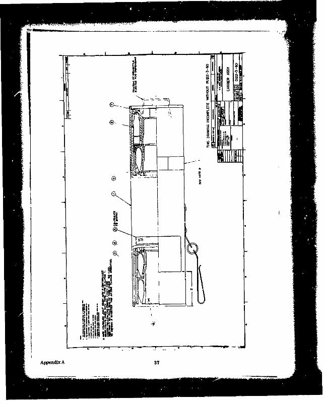
The carrier assembly, drawing D122-3-60 (see Appendix A) contains six projectilesand six blank cartridges in a tubular housing. This housing has a belt clip for Ihstening tothe gunner's belt. The six cartridges are contained in a foam cushion at the cap end of thecontainer. A foam cushion is also provided at the other end to secure the contents duringhandling. The projectiles are individually packaged in a plastic holder and ejector assembly.With the carrier fastened at the belt and with the open end of the carrier down, the pro-jectiles are gravity fed to the bottom where they are retained by an internal ring in thecontainer and are accessible for one-hand loading into the barrel of the launcher. Once theprojectile is in the barrel, the ejector pushes it into the cup. A stop on the ejector bottomsagainst the inner cone of the cup controlling the pressure used to position the projectile inthe cup as well as forcing the cup into the firing position.
The projectile, drawing D122-d-75 (see Appendix A) is a design based on extensivedevelopment work by Edgewood Arsenal. it consists of a molded rubber ring airfoil whichby control of the rubber density can be used also for the Soft RAG Projectile. It is spiralwrapped with a continuous paper strip and secured by a carefully controlled adhesive tomaintain the projectile shape during flight and proper impact characteristics.
12

The cartridge, drawing C122-3-43 (see Appendix A), is a standard 5.56mm primedcartridge case loaded with 12 grains of Dupont 700X gun powder. The nose is crimped andsealed after loading.
DEVELOPMENT EFFORTS
There were three essentially independent development efforts during the program:the launcher, the carrier assembly, -, 2 the projectile.
The projectile de.aign was i result of a continuing Edgewood Arsenal developmenteffort. Refinement and evaluation of the projectile was closely coordinated with the Arsenalwhere all critical testing such as biophysics was conducted and will not be part of this report.
The carrier assembly evolved from concept to final design with only minimal itera-tions during the evaluation and development. There was only one problem of any significance.This problem concerned establishing the retention detent for the projectile in an open car-rier hung from the belt. A reasonable balance between extraction force and retention forcehad to be met to preclude ejection of projectiles via acceleration forces from body move-ments. While no qualitative data was developed, the final design required an abnormal bodyjolt to accidently eject a projectile and its holder/ejector assembly.
The launcher concept and initial design remained essentially unchanged except fordetails during the program with a great deal of the design effort free to concentrate onevolving a producible design. However, arriving at these details changes involved asignificant development effort in two areas: the buffer system and development of the keyson the cup to impart spin to the projectile. The buffer system was especially critical sinceit established the critical loads that would be imposed on the functional parts of the launcher.The development effort in these two areas will therefore constitute the major part of thistechnical discussion.
Launcher Buffer System
With reference to Figure 5, which shows the major functional parts of the launcher -the launcher cup, buffer nut, buffer, and manifold, the launch cycle can be described. Thepropellant gases are collected at the manifold and discharged behind the cup whiph containsthe projectile. These gases accelerate the cup to launch velocity. After one inch of travel,a vent position in the barrel is reached where the gases start to vent to atmosphere. After1-3/8 inches of travel the buffer nut on the end of the cup shaft contasts the buffer and theprojectile otartb leaving the cup. After 2-3/4 inches of travel, the stroke is completedand the cup rebounds back into the barrel, cushioned on rebound by residual gases in thebarrel.
This cycle is further illustrated in Fig-re 6. The curve is based on analysis of highspeed photography of the launcher firing a projectile. The initial displacements and velocitieswere obtained by converting cup rotation, given the lead angle of the barrel grooves, todisplacement. A side camera angle of another firing gave displacemeent after reaching thevent position. The displacement curve shows that maximum energy transfer to the elasticprojectile has occurred at or before the vent position, while peak velocity of the cup ap-parently occurs at time of contact with the buffer. However, velocity Is tending to leveloff at this point.
Both of these points were established by experimental testing to minimize buffer loadswithout compromising velocity of the projectile. An early vent position was desired to assurea minimum velocity of the cup upon contact with the buffer and to permit the installation ofthe longest buffer possible to reduce material stresses in the buffer.
13

Figure 5. Components of Launcher Cup Assembly
T F i IoI. . .. .I... . ... ...
2.5
2.5 - -ISPLAC0A,[NT
BUFFER vtc
10 VEI11 Y BACKd
0 K -0• ,
Nee.vto , s. nl leo0c ri• 114
0prior to f lash at cu p
0 5 5 0 7.5 10 12 5 15 17 5
TIME fseOods x I001
Figure 6. XM234 Launcher Cup Performance
14

The development of the buffer was carried through in the following steps:
* Establish the buffer volume* Evaluate the material* Establish the configuration* Modify the system to shape the force curve.
The establishment of rubber volume, and even the feasibilitv of a one-piece bufferwhich was a contract requirement, was based on published data by Phillip Barkson and
M. F. Sirkin on the "Impact Behavior of Elastomers." (1) This paper explored the follow-Ing areas of the buffer Impact problem:
1. Daration of Impact2. Energy dissipated, or the rebound velocity of mass following impact3. Peak nominal stress, or force produced by impact.
While the data was not directly applicable, since it assumed an unbounded cylinderand a specific material, it paralleled the launcher problem close enough to be used forchecking feasibility.
Two parameters were determined as governing factors:Wv2
W ~ and WL2g AL A
where: W = Weight of Impacting body, lbv = Velocity at Impact, in. /secg = Acceleration of gravity, in. /sec2
A = Cross sectioned area, inPL = Unstralned length, in.
The first term is the specific energy of the system and the second term representsa grouping of functions which appear in the expression for the natural frequency of a simplemass-spring system.
For a buffer thatwould fitthe launcher, where A = 1.539inP, L= 2.75 in., and theimpact mass is 0. 11 lb-
i Wvo22gO = 1872g L =8
and
W.L = 0.190A
By using the referenced curves, one can determine that the Impact period would be0.5 ms, the kinetic energy returned would be 0.2, and the maximum normal stress wouldbe 2,000 psi.
(1) Machine Design Vol. 35, Issue 4, p. 172, 14 Feb 1963.
15

For the short life required by the system, 2,000 psi was a reasonable level towork with, and the fact that the returned energy would be only in the order of 20%
Saeured that the rebound problem would be minimal.
Four elastomers were selected for evaluation, Butyl, EPDM, natural rubber,and silicone (RTV). Their static characteristics are plotted in Figure 7. In generalthe curve indicates a higher spring rate than the RTV buffer previously tested (notshown). This is consistent with the difference In hardness - 43 shore versus 33 shorefor the RW.. The hysteresis was greatest for the butyl with natural rubber having theleast. This verification of the higher "damping" characteristics make It the first choicefor the buffer.
Dynamic tests in a launcher with strain gage load measurement at the end of theshaft were made with identical configurations of apnroximately 40 durometer and firedunder the same conditions, giving the following results:
Mater,'al Average Peak Load Average VelocityLb) (ft/sec)
Natural Rubber 4000 175EPDM 2800 166RTV 2800 -Butyl 2375 173
This data further confirmed the desirability of Butyl and it was therefore selectedas the buffer material.
The energy to be absorbed by the buffer is approximately 80 ft-lb. Ideally, for0.1 ft of travel the energy should be absorbed with a peak force of 800 pounds. As canbe seen in Figure 7, under static conditions, the buffer does not approach this forceuntil travel exceeds 1.0 inch. Under Impact, however, the inertial resistance is veryhigh and to minimize initial contact forces the buffer is designed with a conical nose togive a small initial contact area and inertia mass. A variety of sizes and shapes wereevaluated to assure that initial loads were minimized. The final design, drawing 122-3-29(see Appendix A), kept these initial loads to approximately 1200 pounds. However, peakloads of 2400 pounds or higher were experienced despite experimentation in configurationand hardness.
The problem resolved down to a reduction of buffer resistance to essentially thatwhich would be experienced L-lder static conditions after the initial inertia effects. Thiscan be seen in the strain gage trace, Figure 8, where a dip in the buffer force after initialcontact is apparent. To further optimize this load curve. pneumatic buffing was added tothe syitem and resulted in a nearly optimum square wave shape for the force curve, asshown in Figure 9. The system cut buffer loads in half to an average of less than 1200pounds, significantly reducing loads on related structural elements.
The addition of pneumatic buffing was accomplished by opening up the clearancebetween the cup shaft and the buffer and manifold. 1bis permits some of the propulsiongas to leak back into the buffer chamber where the buffer nut acts as a piston. The pres-sure on the piston provides the additional force required to shape the curve.
Launcher Deflector
An unknown factor in the launcher was the consequences of firing a live round.Initial evaluation of this problem used a simulated muzzle port of the launcher that included
16

" ii|600
meNATURAL // PM
RUBBER"L /
Buffer 4 !Depacement ForceN0 t-ural II Ii 4 1 itButyl 10 in 3% lb
00 0.2 04 0.6 08 1.0 12 14 16
DISPLACEPMIT (inches)
Figure 7. Buffer Static Characteristics
XM 234-1 BUTYL BUFFER XM 234-1 BUTYL + PNEI'MArIC BUIFFER800 lb/Div - .5 Ms/Div 400 lb/Dtv - .5 Ms/DivMaximum Load- 2380 lbs Maximum Load - 1275 lbsVelocity - 208.2 ft/sec Velocity - 200.0 ft/sec
Figure 8. Strain rilge Trace - Figure 9. Strain Gage Trace -Butyl Buffer Butyl and Pneumatic Buffer
17

the deflector. Whdle firing a live round, the deflector as originally designed broke up"and the bullet exiled the test device as two pieces, creating aluminum fragments. Forthe second shot, :t deflector with approximately twice the mass was installed and tested.This deflector ca aght the bullet and retained it in the test device. In both of these teststhe locking nut balding the device to the gu. ba:;rel was retained with 1-1/2 to 2 threads.
* Although the th-eads were damaged the test part did not separate from the barrel underthe impact. A. third shot was fired with a deflector that simulated the final design. Thisdeflector also stopped the bullet as shown in Figure 10. (Device has boen cut in two forexamlnatior.) As an alternate design, a ceramic oai was Installed as a deflector and italso very effectively contained the bullet. This serics of tests effectively determinedtwo methods of stopping the bullet completely in the launcher without external fragmentation.
the test was repeated in an actual launcher and as expected no external fragment-ation resulted. The launcher was damaged as shown in Figures 11 and 12. Fracturingand displacement of the metal housing occurred as the deflector was displaced forwardapproximately 0.04 inch. The bullet was vaporized by the impact, and while cratered,the deflector retained its structural integrity. The flash hider on the rifle, Figure 13,was enlarged by the impact and considerable force was required to remove it. The cupretainee its structural shape and there was no indication of excesgive gas pressure inthe housing.
Launcher Key Configurations
Another critical area in the launcher design was the cup-key/barrel-groove inter-face. The problem was aggravated by the increase in helix angle from 14.6 degrees,previously used in the development launcher, to 16.3 degrees required to meet the soinrequirement of 5000 rpm at the lower velocity of 200 ft/sec. In addition, design require-ments that emphasized producibility and simplicity restricted solutions of the designproblem to those that could be evaluated in a short period.
Two different metal key conflgurations in combination with three types of barrelfinishes were initially evaluated. This was followed by evaluation of basically six dif-ferent plastic key materials in two configurations.
The metal keys were lightweight metal stampings spot-welded to the outside sur-face of the cup. They were tested in a tapered-sided and a straight-sided, or square,groove configuration. The aluminum barrel surface finishes used with these keys wereplain anodize, hard anodize, and nickel Cycle life with these keys was as short as 30shots against a plain anodized barrel, and while the harder surface finishes extended"this life, barrel groove wear was excessive. Correcting for these deficiencies did notappear attractive so an alternate solution using plastic keys riveted to the cup wasinvestigated.
Five basic materials were evaluated in two configurations. The results are sum-marized in Table II.
The 230-cycle l.fe achieved with plain nylon keys, with no apparent wear damageto the lower barrel, led to the decision to fabricate molded keys from plastic for thefinal design. The molded keys would be 50% longer to reduce bearing pressures. Theaddition of glass fiber, based on available data and experience, was expected to resultin a significant reduction in wear. However, tests with keys machined from such ma-terial did not result In the expected reduction In wear.
18
ZN

509
5..
t9I

C)
U
C)C)
C)
�C)
C)
I:mC)E-4
-4-IC)
20

Figure 13. post i~ve Round Test - Flash Hlider
21

Table II
Key Evaluation
Material Confleuration(1 ) Results
1. Acetal Short Limited Life
2. Nylon 6/6 Short 230 Cycles
3. Nylon 6/6, 30% Glass Long 325 - 447 cycles
4. Nylon 6/6, 30% Glass
5% Molydenum Disulfide Long Brittle
5. Nylon 6/6, 30% Glass
15% Teflon Long Short Life
(1) Short key was 0.32 inch long, long key 0.47 Inch.
Variation in glass fill from 15% to 50% did prove a significant parameter, withthe increase in life apparently only due to increased bearing area. It was obvious thatthe "wear" mechanism being experienced was the result of inetantaneous high surfacetemperatures exceeding the melting temperature of nyJ" f (495"F). An alternate materialwith higher temperature capability (Torlon - Amoco Chemical) proved too brittle to with-stand the impact loads. (Testing and evaluation of Torlon keys was conducted by EdgewoodArsenal.) At the end of the development effort, keys molded from 6/6 nylon with 30%carbon fill were prccured but launcher design was finalized before they were available.
This nylon, carbon-fill material was selected on the basis of its higher thermalconductivity which exceeds the glass filled material by over 100%. This material wouldstill have the basic resiliency of nylon to absorb the impact loads and the increased"thermal conductivity should improve cycle life considerably.
It should be noted that total wear in excess of 0.060 inch can be tolerated on the"nylon keys without affecting launcher accuracy and velocity significantly and that this levelof wear is only attained after an excess of 500 cycles. However, after approximately0. 015 inch of wear, impact loads as a result of the increased clearance are high enough tocause structural failure of the key at the rivet, thus reducing the reliable life cycle of thecup assembly. Increased rivet edge distance on the key and possible bonding of the keyto the cup are other design changes that could add to the life cycle capability 01 the launcher.
The lives of other parts of the launcher are shown in Table IlL It is reasonable toexpect that eventually a 1000-cycle life could be achieved with this launcher. Use of thenylon carbon-fill key material alone should improve the cycle life of the cup the 30% re-quired to achieve 500 cycles, and with further refinement of the overall launcher designthe 1000-cycle figure appears attainable.
Table mIComponent Life
Component cycles Remarks
Cup Assembly 379 avg. Key failure
Buffer Assembly 715 No failure
Buffer Nut 715 No failureClip Assembly 523 No failure
Gun attachment 523 No failure
22

Projectile
The XM743 Sting RAG Projectile development was based on the XM742 Soft RAGPrcjec~ile developed by Remington Arms Company, Incorporated, for Edgewood Arsenal.it was designed to be fabricated bý using the same tooling that would be used to fabricatethe Soft RAG. Remington Arni Company was therefore placed under subcontract byDelco Electronics to develop the XM743 Sting RAG Projectile. This development effortis covered in Final Report AB 75-3, September 1975 by Remington Arms and includedas Appendix B of this report.
SYSTEM PERFORMANCE
IPurlng RAM-D tests, the nominal velocity of the round was averaging 8 to 10 It/sec less than that which had originally been obtained with earlitr projectiles and launchers.(Projectile velocity was measured by three screens, five feet apart, with the first screenlocated 3. .5 inches from the launcher muzzle.) It also must be noted that the projectilescontaining the PEG additive weighed a nominal 1 gram over the specified nominal value of34.5 grams. in an effort to determine the cause of the velocity degradation, several stepswere undertaken. The first was to weigh projectiles: it appeared that nominally a 35.5gram projectile was being fired. The second assessment was to break open a number ofloaded cartridges from various lots and weigh the charges. The nominal value of the chargeweight was 11.9. Therefore, an analysis was made to determine the effect of charge andprojectile weight variatiovs. This analysis is as follows:
During the original charge weight selection, 12 grains of propellant gave a nominalvelocity of 203 ft/sec with a 34.5 gram nominal weight projectile. Therefore, given
KE = (1/2) MV2 (1)
and substituting tne values siated rbove,
K 1 34.5 (203)2 48.6 ft/lb (2)KE = 1/2 (454) 32.2
To determine the effect of charge weight variation, the following velocity re-• I ~ ~~lationship was used:v=34II•p -W
S[W V =344. 1 vw
where CW is the chnrge weight and PW the projectile weight. The results are shown inTable IV.
Table IVCharge Weight and Projectile - Effects on Velocity
Velocity (Ft/Sec) Velocity (Ft/Sec) Velocity (Ft/Sec)Projectilea at 12 at 12.2[] [] [] •W e igh t tg r a m s ) a t 1 1 . 8at 1at 2 .
Grain Charge Grain Charge Grain Charge
33.5 204.2 205.0 207.7
34.0 202.7 204.4 206.0
34.5 201.0 202.9 204.6
35.0 199.8 201.5 203.1
35.5 198.4 200.1 201.7
36.0 197.0 198.7 200.3
36.5 195.7 197.3 198.9
23

It can be seen from this calculation that charge weight has a minor effect ascompared to projectile weight - Figure 14 show, velocity plotted versus projectileweight.
210 I I
•_ I • ! 10 SHOTS ON,205- • ,4 LAUNCHERS,
A ,,
I I
21j Fiur 14 -1at es el6iy8.3%t 3
Z; -2 .... %
LauncherRA Dell WT i 35.6595.
IDES IGN W T 34.5±1 i-
ISO I
33.9 33.5 34.0 34.5 35.0 35.5 36.0 24 5 37.0PROJECTILE WEOGHT19)
Figure 14. Start Test Velocity Estimate
The four launchers used durinmg the RAM-D test exhibited the follow,.ing standarddeviation around the mean velocity (i):
Velocity (x)Launcher Serial # O1l I ar 3.65 195.5
Launcher 015 1 a 4.024 196.8
Launcher 016 1 a 4.314 194.2
Launcher 019 1 a 2.767 195.7
Velocity degradation with these launchers is shown in Table V.
Table V
Velocity Degradation
S trial No. Velocity Degradation Trend
Launcher 011 0.023 ft/s per shot
Launcher 015 0. oil ft/s per shot
Launcher 016 0.009 ft/s per shot
Launcher 019 0.010 ft/s per shot
This shows an average trend of 0. 01325 ft/s. Assuming 365
shots, the expected degradation would be 4.8 ft/s.
24

The mean velocity and the standard deviation are calculated for the four blunchersused in RAM-D.
M=I!N 1 N Inm (4)
m=1
2 1 (Nm-1) +E N x = N (5)N-i M= m= I
This calculation yields an average velocity (X) = 195.4 ft/sec. On the total of 1,462
rounds fired in RAM-D, the estimated trend of velocity versus projectile weight is shown in
Figure 14, as well as 1 a value. This plot is for the start of the test. This graph shows
that the mean velocity at the start of tests assuming a 35.5 grain projectile would be about
200 ft/sec. As a croos-check the first ten rounds from each of the four launchers were
used to calculate actual experience (Table VI). Note that the mean velocity X = 199.53 ft/
sec and is indicated by the plot. There is a possibility that some round would fall below
190 ft/sec. As indicated in Table VI, there is one round out-of-specification.
The total number of rounds on the four launchers was 1,462 rounds and shows an
indicated average of 365-round capability for a given group of launchers. A velocity degrada-
tion trend of 4.8 ft/sec (for all the launchers) was calculated. The 4.8 ft/sec shift in mean
velocity is shown in Figure 15, again with a -3o" bounds. By definition 1O = 68.3%;
2 r = 95.4%; and 30 = 99.7% of the population. The interpretation of these plots is that in
the Lnitial firings less than 1% of the shots would be out-of-specification, and, after an
average life of 360 rounds, less than 5% would be out-of-tolerance. A cross-check on
ordering of 1,083 rounds on three of the launchers which lasted at least 360 rounds is given
in Table VII. As can be seen from that ordering, 3.7% of the rounds are out-of-tolerance.
The conclusion, therefore, is that with an in-specification weight projectile, less than 1'*
of the velocities would be out-of-specification with a launcher, assuming an average life
of 350 rounds.
25

Table VIMean Velocities of First Ten Rounds from
Each of the Four Launchers
SI I-30 -20 -Wa Mean +la
187.970 188. 288 192.036 195.783 199. 530 203.278
193.050 196.078 200.000 204.082
193.050 196.850 200.000 204.082
193.798 196.850 200.000 206.612
194.553 196.850 200.803
195.313 197.628 200.803
198.413 200.803
198.4J3 200.803
198.413 200.803
198.413 200.803
199.203 201.613
199.203 201.613
201.613
201.613
202.429
202.429
203. 252
203.252
203. 252
"203. 252
26

'0T z
rE* 0v
4. r.. .. .. . . . ~. f.J.~... . . . . . .. . . . .• . . ... . ... . . . .
S . . f...t ýj * 40.j .. jt. j ..J ar.,J (.o .. . . j.. .- jC .. * . . . . .1i . . f . . (. N . . . . . . . .
a.* .. . . . .... . . . . I . . ... . . .o . . . .. . .. . . ..
* _
C.7.0 OG
'0 0 0' ' '0...0 00° ".. ) 0., " . .).)*°,) ' " *** . .. . . . .. *0 • .0 4.. * * * * .4
60 ,m ,r Or W• V fan Vb • )1,V nV )n6 ns, b W lik .u ,01ýU ýnV
S.................................... o.......... . ..... . •
U, '° . 0.......... 00..'4a0 4.O C o*.0O
z0 ID C I D;f , , D - D, 4,D
m w w w w o m W-w2 0 mo MO D( D4 D0( DO D.k0O 5CO . O0 00
o a-0-0 .,0- .4 ,D ý ,0- --- , ' . D 0No. -~, 4 , & 4
c '
o,D o -) a oD,& a .0 'AD .01 A JO'-A D- 0 -' ,''ao-,a ,w .aa ,w ,a ,a o ýa ,a ,V 0 ,. 0 ,(,0 (.0 .c.0 ,(p ,a .(,U ' e . ý(,a %aa ,0 ,V r
.4404 .~ .... ' .7444000~ .)' .0C '04
.4 4 4 4 0 0
.4~ .40 .'0 '
.' .. .,! .. 4-~
(,* ~ ~ ~ ~ ~ ~ ~ ~ ~ ~~1 W:004. 0.*.4'. U4..00.'' . '~ , ~ : ", W:C U'4 W, 7, 04 '-7 :..' V*.. r, - ' : :
4.,.
0* 7.
G0444..70, a.7a..7a,..7.0.7v7.a.70.07.7t.7.7C.C Q @Y, 0C..OC.Oa" 0... a,....
,0 41 ID IM 0 CD .1.0 0 4.10 1. W OD 0 M . 0 C .D OD C! . D 0. IOD 0 W . 0 W W. OD OW . 0 CD45 7.40.4.M.04. 4n.<D44.494.
UU
-4J!
QD
- - - - - - - - - - - T~ - - - - - - - - - - - - - - - - - - - - - -
1* inar orUO~'."AC'

' . - . .. . . . . . . . . . ... .. . ..7 V .~ . I .' V . V t.. V V. .V . .
4D~ 00 CDODa 00 Cl, -0 00 0:., 2) 3) w00 0 0 Q-. -11 12O 212000000000 T@ T em n 00
7 '. P. . . .3 ' - . . . . . . . . . . . . . . . . . . . . . . . . . . . .
- -t - Ig -~ -C - - -. ~ -. b -. -
* 00000 ~ ~ ~ ~ ý O. 0"01 0!000 V! 00!0 C. 0! 000000000 0!0 mom-DC. .. .. . .. .. . .. .. . .. .
-----------------------------------------
- -. . . .. <4T. c
"27/2Bes AvfIbf CopyýO-4ýA nVW W ýW r W"b'' .

SI DESI N WI 3-.5--
2529
205 -ILIMEASURED 360 1--
~20 ... ="• i-rA• •LAUNCHERS
S195 I
_ _ • .> 1 9 0 7 %•
I•"T" • I' """" PREDICTION 2.467%'
; 180ISOI DESIGN WT 34.5f]. • 1'
33.0 33.5 34.0 34.5 35.0 35.5 36.0 36.5 37.0"• '•PROJECT ILE WEIGHT (9)
S~Figure 15. 360-Round Velocity Estimate •
_29

SECTION 1ITESTING
A variety of individual component and assembly tests were performed during the con-
tract period. Total recorded firings and demonstrations, excluding RAM-D tests, numberedslightly over sixty-six hundred, 6617. It should be noted that this number does not reflectEdgewooa Arsenal testing, which during the additional projectile testing was significant.
Early development testing was completed by using old Mk III and IV parts. As the- mXM234 design solidified, a machined launcher was produced. Under careful observation,
tests were planned which combined compatible piece part investigations. In December1974, the first machined launcher castings were completed. Prior to this a total of 1109test firings were performed by using Mk III, Mk IV, and the totally machined XM234 hard-ware. Critical design areas were investigated by using electromechanical instrumentation.Three types of instrumentation were used extensively: 1) velocity screens, 2) pressuretransducers, and 3) strain gages.
Velocity screens were used in development as well as RAM testing. In developmenttests the screens were used as a baseline for analysis. As testing progressed, the screenswere used to finalize propellant load. All of RAM testing was completed by using the screensto monitor the velocity criteria.
"Pressure transducers were used to obtain data for formal launcher and projectileanalysis. With pressure transducers located in the buffer chamber, in the plenum chamberbelow the flash hider, on the top of the plenum chamber, and behind tie launcher cup, pres-sure traces were obtained. The pressure data obtained is shown in Figure 16. By modifyingthe transducer positions to receive pressure profiles in specific chambers, data was re-ceived for acceleration analysis during projectile development. Transducers were locatedas shown in Figure 17. The pressure traces received during the projectile developmentrevealed an almost optimum acceleration profile. Further Edgewood Arsenal analysisconfirmed this data.
Early advances in strain gage mounting techniques which increased the gage lifemade it an extremely useful tool. Gages mounted in the shaft of the launcher cup help toidentify and trace high stress areas. For example, with the strain gage as a direct readoutof buffer performance, rubber materials and configurations were evaluated. After theootlmi7ation of the buffer design, testing continued by using strain gages to optimize other"design requirements in areas such as the launcher cup assembly.
A significant amount of development testing was performed at Edgewood Arsenal,most of which can be classified in two areas. The first area Is biophysics tests which wereperformed solely at the Arsenal. Their tests indicated that the projectile when fired withinthe velocity limitations, 205 ± 15 ft/sec, is not lethal. The second area was that of projectiledevelopment.
On 21 November 1974, a projectile stitus review and test was conducted at DelcoElectronics. Edgewood and Remington representatives were present and based on this re-view and preliminary biophysics testing the projectile design was frozen. The interfaceDecember 1974 monthly drawing R022869, Rev. D appears in Appendix A.
30

-1600
-1400
600- 1200
500 1:1000
4 - --8
0~
UJ- iL• J
a-.
300 1+. - 100
200 400 lo
1400 200• -
0.2 0.4 0.6 0.8 1.0 1.2 1.4TIME (ms)
Figure 16. Results of XM234 System Pressure Tests
31

BarrelSPlenum /
00Buffer
Pe u
Flash Hider
Figure 17. Pressure Transducer Chamber Locations on rest Launcher
On 29 and 30 January, a projectile specification meeting was held at EdgewoodArsenal. At this meeting, high-speed films were taken of th - projectile fired from the XM234launcher which disclosed a problem of projectile wrapping biLeakage on launch. This problempreviously has gone unnoticed because breakage of the 20 wraps/inch projectiles, as receivedand used exclusively in preliminary RAM-D tests, had not deterred flight and did not appearsignificant. A quick check of the approved RAM-D projectiles, as received at Delco Elec-tronics (17 wraps/inch), revealed band breakage on every launch and severe deteriorationof accuracy.
Extensive projectile tests were scheduled and performed to resolve the projectileband breaking problem. The majority of the firing tests were conducted at Edgewood. inaddition, the following objectives were outlined:
* Remington Arms would conduct an engineering investdgation to evaiuate:1) a band wrap with moisture-resistant properties and specific straincharacteristics, and 2) an alternate projectile material to attain theminimum launch stresses and strains.
* Delco Electronics would develop and test launcher alterations that wouldminimize launcher acceleration and projectile stresses and strains.
In support of the Edgewood-requested effort, Delco initiated investigations in thefollowing areas:
* Launcher sealing to reduce propellant load* Flow modifications to receive softer launch* Projectile spin rate reduction to 4,000 revolutions/minute* Additional cup support of the projectile.
32

As reflected in the current projectile design (see Appendix A), projectile modifica-"tion was selected as the solution to the banding breaking problem. The final evaluationtesting was conducted at Edgewood Arsenal on 5 and 6 June 1975. At the conclusion of thetest program, agreement was reached by Edgewood, Delco, and Remington on the processand materials to be used in completing the fabrication of the Sting projectile. These ze-quirements are also reflected in the attached drawing.
From 27 June 1975 through 14 July 1975 Delco conducted a reliability test, demon-stration, and evaluation of the Sting RAG VI Civil Distur.-nce Control System. The testprogram was witnessed in total or in part by representatives from Aberdeen ProvingGround, Edgewood Arsenal, and Fort McClellan. Test resultr and analysis were completedand distributed as stipulated in Mod P00002 of the contract.
33/34

I
APPENDIXES
A Copies of Print Numbers
E 122-3-30 Launcher 36
D 122-3-60 Carrier Assembly 37
D 122-3-75 Projectile 38
C 122-3-43 XM755 Cartridge 39
C 122-3-29 Buffer 40
R 022869, Rev. D XM743 Projectile 42
B XM743 Sting RAG Projectile DevelopmentStudy (Remington Arms Company, Inc.) 43
35

i A I
ea_
Appen!jj!,3
L
--
lis
.n
A
I37* ' p." '
'
•iIII
II
Appendix
A
37/!
i

gKý
R U_
w
I i/
of 0
PL~ - I
S tow)
4~==-== C.,
uJJ
-u .u tu
fit %Z 3
-4
Appendix A 38

Cr) PR, K to
Ito LM) 3 g-4
-P2 20. <
I ri_
cin
1w
'910011
iavw
f-
I.
'9%R.
ir 9
~tL-ON
31
fil a*, ZI -. m
Ar,,endixA 39

~c g45 w I m
Kz''I -' r
i-,Vni A 4

-*zzmceuaý,7 cb1" 44
Wt~
< <
-~ 0*
cIi-
oI~2 0
.~0 -~ \A
'lb
LulliýA~g~)
ROD -
Appendix A 41/42

AB 75-3
DELCO STUDY CONTRACT
FINAL REPORT
Purchase Order 13501, Amendment 3617Under Government Contract No. DAAA15-74-C-0262
September 1975
Final Reportby
Kenneth W. Misevich
Work done by: K.W.. iisevichJ.J. ScanlonC.L. Jackson
Appendtx B 43

TABLE OF CONTENTS
Page
Introduction ................................................... 46
Objectives ..................................................... 48
Summary ..................................................... 49
Experimental Details .......................................... 51
Sting RAG Production Process: Breakband and Rubber Cement ..... 63
Recommendations ............................................. 65
Appendix r= 44

TABLES
Table No. Pag
B-I Task No. 1 Tensile Tests 55
B-11 Task No. 2 Tensile Tests * 57
B-1Il Typical Production Breakband Tensile Tests 62
'.-LUSTRATIONS
Figure No.
B-1 RAG Band Drying Cabinet 66
B-2 RAG Drying Cabinet Process Cycler 67
B-3 RAG Rubber Cement Dipstick Applicator 68
Appendix B 45

....... .......
INTRODUCTION
The work described in this report is the result of a special study
contract from Delco Electronics Laboratories to Remington Arms Company,
Incorporated, (Amendment 3617 of Purchase Order 13501, ander Government
Contract No. DAAAl5-74-C-0262). The main goal was the improvement of the
launching survival of the XH-743 Sting RAG projectile in the XH-234 launcher.
The Sting RAG projectile is similar to the Soft RAG (XM-742) projectile
developed by Remington Arms Company, Incorporated, for Edgewood Arsenal,
Maryland, under Contract No. DAAAl5-73-C-0047, except the Soft RAG disseminates
CS-2, a riot control agent, on impact and the Sting RAG does not. These
projectiles are ring airfoil shaped which provides low drag, making it
possible to launch them at a low velocLty of 200 fps. This, in combination with
the soft, low durometer rubber-bodied projectile, results in a kinetically
non--hazardous pro3ectile. To maintain the airfoil shape at the launch
conditions of 200 fps and 5000 rps, a wrapped tissue breakband that is supple,
yet of low ultimate break strain was developed. Since the Soft RAG must
disseminate the riot agent on impact and graze against hard and soft targets,
the breakband was designed to maintain a yield strain of 1-1/2 percent to
3 percent over all specified environmental conditions while holding a nearly
constant tensile strength. This band was, therefore, used for the Sting RAG
as ballistics and projectile weights are identical to the Soft RAG projectile.
The banding material is Aldex 17 tissue (Gould Paper Company, New York)
cut in 1/4 inch widths, folded in half to 1/8 inch and impregnated with
ethylene vinyl acetate (EVA), Du Pont Slvace® 1968. After experimentation with
Appendix B 46

the Soft RAG dissemination characteristics, the best wrap rate was found to be
between 17 to 20 per inch. The banding operation consists of banding six
projectiles at a time, dryin93 the tissue wetted with the EVA binder in a
forced convection chamber, catting the nose and tail ends to produce the tissue
breakband, drying overnight, and crosslinking the EVA by heating for three
minutes at 3000P. In the dry state the breakband ultimate yield strain is
1 to 2 percent, and wet 3 to 4 percent with a tensile strength of about 4500 to
5000 psi. (The tensile stress is based on a nominal cress section of 0.003 inch
x 1/4 inch per wrap.)
Both the Soft and Sting RAG projectiles were test fired at Delco in
November 1974 with excellent results. But in January 1975, further test firings
at Edgewood Arsenal (and concurrently at Delco) revealed a launching survival
problem for the breakband .when in the dry, low ultimate strain condition. Only
humidification, which increases the ultimate strain to about 3 percent, allowed
the breakband to survive the complex launch dynamics.
A study was initiated to review the breakband mechanics and the rubber
body distortions caused by the launch forces. This study showed that the
combinati:rn of suppleness and low ultimate strain would be very difficult
to obtain with available non-fibrous materials, so Edgewoci Arsenal decided
to pursue a course of permanent breakband plasticization. A change of the body
material for the Sting RAG from NordelO& elastomer to a butyl rubber was also
considered because Delco's work on the XM-234 launcher _indicated that this
formulation would be slower reacting to the dynamic L-unch forces due to its
"better damping characteristics.
Appendix B 47

OBJECTIVES
The goals of this study were very specifically set down after initial
experiments at Edgewood Arsenal indicated that polyethylene glycol (PEG) of
low molecular weight (300) would increase the ultimate strain of the breakband
when added to the ethylene vinyl acetate (EVA) breakband binder. The purpose
of this study was to determine the best material combination and process methods
through five fabrication and testing tasks per Amendment 3617 of Purchase Order
13501 under Government Contract No. DAAAl5-74-C-0262. These tasks are described
below:
1. A. Fabricate 144 projectiles wrapped at a rate of 20 wraps per inch,
using the three PEG binder ratios (48 projectiles each) shown below
and without the oxalic acid cross-linking catalyst in the EVA.,
48 XM-743 projectiles with 15% PEG added to EVA
48 XM-743 projectiles with 20% PEG added to EVA
48 XM-743 projectiles with 25% PEG added to EVA
B. Test the breakbands of six projectiles for strain and ultimate stress
according to the following: Two breakbands from each lot under dry
conditions (24 hours storage at 1201F); two under wet conditions
(24 hours storage at 100*F and 100% relative humidity); and two at
ambient conditions.
C. Submit the remaining 42 projectiles from each group to Edgewood
Arsenal for firing and biophysics tests.
2. A. Fabricate 48 additional projectiles using the best PEG/EVA binder
ratio as determined by Edgewood Arsenal tests on the above samples.
Appendix B 48

B. Test the breakbands of six projectiles for strain and ultimate
stress as defined in Task #1, and submit the remaining 42 projectiles
to Edgewood Arsenal for tests.
3. Fabricate 96 projectiles with a butyl rubber to be supplied by Remington
Arms Company, Inc., wrapping half at 17 and the remainder at 20 wraps per
inch. Divide these two lots in half, coating one lot with EVA and the
rest with PEG/EVA binder selected in Task 1-C.
4. Fabricate 96 projectiles with a butyl rubber material furnished by
Delco. Wrap and coat as done in Task #3.
5. Prepare 48 talc-filled Soft RAG projectiles (XM-742), wrapping 24
projectiles at 17 and the remainder at 20 wraps per inch. Coat these
with the PEG/EVA binder employed in Task #2, but cross-link all
projectiles. This was not done in Task #2.
Other tasks included: Investigating the introduction of the polyethylene
glycol into the Sting RAG manufacturing process (Task #6); and technical
meetings and testing at Edgewood Arsenal and submitting this final report
(Task #7).
SUMMARY
Pro3ectiles tested in Task #1 performed about equally well, but the
binder with the 15% PEG added to the EVA was selected since it produced
the best breakband integrity and processibility. Even though the breakband
strains are about 3 percent as desired, the addition of the PEG causes a
problem. The PEG greatly reduces the adhesive quality of the EVA which results
in repeated instances of the breakbond unwinding from the leading edge of the
projectile in flight. To determine whether consolidating the nose portion
Appendix B 49

of the breakband wrap would prevent the unwrapping half of the Task #2
projectiles were dipped in pure EVA. But, this was not effective.
Since Du Pont's butyl formulation, which met the ASTH specification
that Delco requested, could not be processed in the available molding equipment
the regular 30 percent brass-filled Nordel® elastomer was substituted for it
in Task #3. The 96 projectiles fabricated were divided into four test groups:
1) a control group, 2) extra wet binder applied, 3) post-dipped over 1/4 inch
of the nose portion of the band with the 15 percent PEG/EVA binder and, 4) with
the breakband cut off about 1/16 inch further back from the nose. All projectiles
were dried for one-half hour in a blower chamber and then one hour at 1301F
to insure that a good clean breakband cut off from the banding mandrels would
result. These projectiles were then hand-carried to Edgewood Arsenal by
R.E. Belden for a joint testia~g and technical meeting on June 5, 1975.
Firing tests of the variously banded projectiles permitted agreement
on the final band properties which provides adequate performance. Under the
worst conditions of dryness, it was found that the breakbands plasticized
with the polyethylene glycol could still have some small breaks at the nose.
"These breaks, opened by the spin and aerodynamic forces are undesirable. Since
no reasonable way of positively eliminating these breaks was possible within the
time scale of the program, it was decided to minimize this effect by coating
the nose of the finished projectile with rubber cement.
The Sting RAG breakband specifications are as follows:
w Wrap with the Aldex 17 tissue at 20 wraps per inch.
* Coat tissue binder consisting of 15 percent polyethylene glycol
(Union Carbide Carbowax 300) added to plain Du Pont Elvace& 1968.
Appendix B 50

* Dried at 501C for 20 minutes by forced air blower.
* Cut the band in the nose and tail sections.
9 Coat nose with a thin application of rubber cement (B.F. Goodrich
Vulcalock) about 1/4 inch.
Details of the task activities and the process description are given in
the following section.
EXPERIMENTAL DETAILS
Since this contract was only for a month and many variations were made
throughout, the work is presented chronologically for clarity. Then, a summary
of the process conditions is given.
5/19/75 Work began with wrapping trials utilizing samples of Union Carbide
Carbowa.-- 300 provided by Edgewood Arsenal. A number of observations were made:
" The addition of PEG to the EVA forms a much thinner binder.
"* The PEG greatly decreases the EVA resin build-up on those
surfaces exposed to the wetted tissue.,
"* Intra-wrap adhesion is much less to the point where the breakband
can be unwrapped without tearing even after it is dried completely.
M ,uch longer drying times (an hour or more compared with the previous
15 minutes) are required before band cutoff can be done.
* Even after apparent complete drying, the cutoff is difficult and in
some instances tearing or pulling occurs.
e As-the percentage of PEG increases the breakband gets a more "oily"
or "wet" feel.
Appendix B 51

At the initiation of Task #1, the 15 percent PEG/EVA binder solution
was made as follows: 75cc of Union Carbide CarbowaxO 300 were added to 500cc
of plain 50 percent solids Elvace 1968 to create the 15 percent binder ratio.
At fixst the projectiles w:ith 20 wraps per inch breakbands were coated with
this solution and dried 1/2 hour before attempting to cut the bands. Many
tears resulted so the drying time was increased to one hour. But, the cut off
was still not uniformly clean.
Finally, pco~ectiles soaked for one hour at 130*F, cooled for one hour
at room temperature and then crosslinked by heating them at 3001k, for three
minutes, produced good, cleanly cut bands.
To make the 20 percent PEG/EVA solution, 17.5cc PEG were added to the
405cc of the 15 percent PEG/EVA binder and the process was repeated for
another 48 projectiles. The 25 percent PEG/EVA solution was made by adding
llcc of PEG to the remaining 260cc of 20 percent PEG/EVA solution.
Six projectiles of each binder ratio were set aside for tensile
testi•g.,
5/20/75 The butyl rubber formulation procured by Remington A Company, Inc.,
was requested only in a sample quantity of 10 pounds since the moldability
was never demonstrated in our press., While Du Pont felt that the Nordel®i
elastomer formulation could be effectively repeated in butyl, the actual sample
was ordered according to the Delco specification (ASTM D2000,3BA520B13Z Z ;Z =1 2 1
40 - 5 Shore "A", Z = Butyl) provided verbally on March 6. The sample was
received on April 15 and was tried immediately. But, it was too stiff to be
transferred into the mold. Du Pont suggested pre-heating the molding billets,
but no further trial could be made until May 20.
Appendix B 82

Various pre-heating cycles were attempted but none softened the material
sufficiently so the 2000 psi available in the transfer press could hazdly
fill the mold. Preparations were then mane to order another sample with better
processibility. (The order was cancelled May 30 at Delco's direction to sub-
stitute 30 percent brass-filled NordelO elastomer for the Remington-supplied
butyl in Task #3.)
5/21/75 The Task #1 projectiles were shipped to Edgewood Arsenal under Remington
Arms Company, Incorporated, shipping memorandum TD 1931. Eighteen tensile
samples, six from each binder ratio, were made by cutting the breakband and taking
eight wraps from the portion over the body cavities. These strips were then
cut to 7-inch lengths, covered on each end by 1/2 inch masking tape and put into
the test storage. Three from each binder ratio were stored for 24 hours at 130°F,
and 24 hours at 10*F and 100 percent R.H.
The Delco-supplied butyl arrived and was immediately checked at the same
settings used for the Nordel®) elastomer, that is, platen temperature to give
350.F molds and 1600 psi transfer pressure. But, after five minites the
butyl rubber did not fully cure. The time was increased gradually until full
curing was effected at 10 minutes.
Butyl rubber pro3ectile bodies were then made in a twu-step process:
Five minutes in the transfer press, five minutes in the hydrau3ic press at 350*F
and then stripped. Altogether, over 100 projectile bodies were made. The molds
had to be periodically cleaned of a black residue which was produced from the
filled butyl. The build-up was much faster than with the brass-filled Nordele
elastomer.
Appendix B 53

5/22/75 The tensile tests were conducted o.i the eighteen breakband samples
from Task #1 with the Instron driven at 0.2 inches per minute and the chart
at 10 inches per minute using a 20-pound full scale. The results are shown
in Table B-L Note that the yield strein is determined by the displacement
from the extrapolated zero strain to the point of first maximum stress. Later,
Edgewood Arsenal defined the yield strain using the best straight line
through the 5 and 15-pound readings. For this reason, Edgv¢c-..'s method
usually gave a slightly higher strain value to yield.
5/23/75 The Task #1 projectiles f.red at Edgewood Arsenal flew well but the
breakband unraveled from the nose. In a meeting after the test, methods to
prevent the unraveling were discussed, namely: use sharper cutoff knives,
"add more binder to nose region, use a different drying cycle before cutoff,
or try separate EVA and then PEG impregnation.
5/23/75 Butyl projectiles fabricated by Delco were checked for Shore "A"
durometer. They were averaged between 30 and 35 instead of 40 ± 5. Nothing
could be done to correct this situation in the time period available.
5/27/75 According to verbal instructions from Delco, the banding of the Task #2
projectiles was to be done using the 15 percent PEG/EVA binder ratio applied
extra wet, Half of the 4e projectiles had additional pure EVA applied to the
nose region of the breakband while on the banding mandrels. (The EVA was dyed
red for identification.) One half hour of blower drying and one hour at 130*F
preceeded the cutoff which was done with new knives. Then all of the projectiles
were dried further for 24 hours at 130-F.
Appen'Ux- B54

TABLE B-1
TASK #1 TENSILE TESTS
Tensile Yield BreakBinder Max. Force Strength Strain StrainRatio Condition (lb.) (psi) (%) (%)
15% PEG Wet 7.75 1292 3.2 4.215% PEG Wet 7.30 1216 3.7 4.615% PEG Wet 8.10 1350 3.9 5.6
Average 1286 3.6 4.8
20% PEG Wet 6.95 1158 3.2 5.020% PEG Wet 6.85 1142 3.4 4.520% PEG Wet 6.50 1083 3.3 4.8
Average 1128 3.3 4.8
25% PEG Wet 7.10 1183 3.0 4.325% PEG Wet 7.30 1216 3.4 4.925% PEG Wet 6.70 1117 3.0 4.4
Average 1172 3.1 4.5
15% PEG Dry 18.00 3000 3.0 4.815% PEG Dry 17.00 2833 3.1 4.715% PEG Dry 16.05 2675 2.8 1.0
Average 2836 3.0 4.5
20% PEG Dry 16.40 2733 2.9 4.520% PEG Dry 18.30 3050 2.9 3.620% PEG Dry 16.55 2758 3.0 4.4
Average 2847 2.9 4.2
25% PEG Dry 15.45 2575 2.7 3.725% PEG Dry 15.60 2600 2.9 3.525% PEG Dry 14.30 2383 2.5 3.4
Average 2519 2.7 3.5
Wet Condition - 26 hoirs 100°F and 10C% R.H.Dry Condition - 27 hours 130 FTensile Specimen - 8 wraps by 6 inches effective length,
.003" x .25 x 8 cross sectionCross Head Speed - 0.2 inches/minute
KWM:KLIK8/6/75
Appeadix B 55

5/28/75 Molding of the projectiles with Delco-supplied butyl was completed.
A TWX from Delco was received confirming the 5/27/75 verbal instructions.
The Task #2 projectiles were hand-carried to JFK airport to Mr. Robert Peterson
under Remington Arms Company, Inc., shipping memorandum TD 1938.
Six tensile specimens were made from the Task #2 projectiles and put
into wet and dry storage.
The XM-742 package machine was set up in preparation for the requirements
of the Task #5 XM-742 projectiles.
5/29/75 The packages for the XM-742 projectiles of Task 15 were made., Tensile
tests on Task #2 breakbands were run. The results are shown in Table B-fL
5/30/75 A TWX was received from Delco directing that Nordel® elastomer be
substituted for the Remington-supplied butyl in Task #3. All projectiles
were to be prepared using 20 wraps per inch with 15 percent PEG/EVA binder,
dried one-half hour with the blower and then an hour at 130"F before cutting
off. The projectile breakdown was:
- 24 projectiles with leading edge of breakband cut back
.050" to .060" further than normal.
- 24 projectiles after drying dip the projectile nose about 1/4
"inch into the 15 percent PEG/EVA binder.
- 24 projectiles with even heavier binder wetting in impregnation.
- 24 projectiles made in the normal manner.
In aadition, 48 of the Task #4 projectiles were banded according to the
previous production banding operation, half 17 wraps per inch and half 20 wraps
per inch.
The Soft RAG XM-742 projectiles were assembled for Task #5.
Appendix B 56

TABLE 9-fl
TASK #2 TENSILE TESTS
Tensile Yield BreakB'nder Max. Force Strength Strain StrainI&tio Condition (lb.) (psi) (%) (%)
15% PEG Wet 6.85 1141 4.0 5.615% PEG Wet 7.60 1268 4.2 6.215% PEG Wet 7.80 1300 4.0 5.2
Average 1236 4.07 5.67
15% PEG Dry 17.7 2950 2.5 3.515% PEG Dry 18.5 3083 2.7 5.115% PEG Dry 19.6 3267 2.9 No Data
Average 3100 2.1 4.3
Wet Condition - 24 hours 1000F and 100% R.H.Dry Condition - 24 hours at 130OFTensile Specimen - 8 wraps by 6 inches effective length,
.003" x .25 x 8 cross sectionCross Head Speed - 0.2 inches/minute
KWM:KLK8/7/75
Appendix B 57

Projectile molds were cleaned and repaired as required.
6/2/75 Mr. R.E. Belden of Edgewood Arsenal observed the production of the above
144 Tasks #3 and #4 projectiles.
6/3/75 The Task #3 and half of #4 projectiles were hand-carried by R.E. Belden
to Edgewood Arsenal under Remington Arms Company, Incorporated, shipping
memorandum TD 1946.,
6/4-5/75 A trip was made to Edgewood Arsenal to observe the test firings of
the Task #3 and #4 projectiles. All of the humidified projectiles flew well
without band breaks and all of the dried projectiles (24 hours at 130*F) had some
sort of breaks or cracks in the band near the nose, It was found that the spin
up to 5000 rpm in a wind tunnel at 210 fps would open these cracks and probably
cause flight irregularities. In longer range firings this would be a problem.
The overall situatior was discussed at length and it was decided to coat
over the nose end of the breakband with rubber cement to help maintain break-
band integrity during flight even if a crack developed. It worked well.
The final Sting RAG configuration was set by consensus as described
in the summary, previously. Only specification of impregnation, drying before
cut off and rubber cement application remained.
A discrepancy in the yield strain values existed between tests at Edgewood
and Remington Arms Company, Inc. This resulted since Edgewood Arsenal uses the
best straight line through 5 and 15 pounds for dry specimer3 and then calculates
the yield strain from the abscissa when the ordinate is maximum force. To
alleviate the discrepancy, Edgewood's method was adopted for further tests at
Remington Arms.
Appendix B 58

6/6/75 A TWX from Delco authorized the rewrapping of the 3000 Sting RAG
projectiles which were already delivered to Delco under P.O. 13501 and fabricated
by the old method. In addition, the 48 balance of the Task #4 Delco butyl
projectiles and the Task #5 Soft RAG's were to be banded also at 20 wraps per
inch and coated with rubber cement.,
6/q-10/75 The wrapping of the Task #4 and #6 projectiles was completed. The
B.F. Goodrich Vulcalock rubber cement was applied by hand with a coffee stirrer
while hand turning the projectiles which were made for special tests. It was
decided to hold up the cement application until the procedure was refined.
During the final wrappin9 it became obvious that the drying time before
cut off was too long to get any kind of production rate at all. A new drying
cabinet was, therefore, considered necessary for the hot forced air drying.
A special check was made of the impregnation of the binder into the tissue.
About ten feet of tissue was drawn through the impregnator at the normal setting
of the squeegee. The weight was 24.5 grains. The same length without binder is
6.2 grains s.- 18.3 grains of 15 percent PEG/EVA was deposited. After drying
for 30 minutes at 120°F the weight dropped to 18.0 grains, a loss of 6.5 grains.
This indicated that not all of the 50 percent water in the EVA had evaporated,
since 15.9 grains of TVA should be contained in the 10.3 grain total., The water
content is 7.95 grains initially so 1.45 grains or 18 percent of the water
remains in the band presumably because of the PEG.
Tightening of squeegee down to the driest attainable impregnation
setting still yielded 25 grains for the wet tissue and binder. The impregnation
is totally insensitive to squecqee pressure in the impregnator being used.
More binder could not be added to the tissue until the squeegee was actually
Appendix B 59
lifted from the tissue. This situation is, of course, irrelevant.
6/11/75 A plywood cabinet was designed to accommodate standing mandrels from
the wrapping process in a lower 12" x 16" x 12" high chamber, and a Nutone
Model 9605 Heater/Ventilator above. (See Figure B-i)
6/12/75 The breakband drying cabinet was built and assembled for operation.,
6/13/75 Experiments with the drying cabinet showed that the air was entering
the chamber at about 70C but in the center of the chamber had dropped to 50C
because of mixing with air from the 3" x 16" opening above the door in front.
In order to be consistent in band drying in a continuous process, a special
cycling 3ig was made to space and move the mandrels as they were wrapped.
As Figures-2shows, the mandrels are set into the center of the cabinet from
the rear to the front. When one set of four are wrapped, the sliders
uniformly mcve the stacked mandrels about 3 inches to the left leaving room
for four more. When eight sets are wrapped in acout 20 minutes, the first
one is dry and is removed from the left rear of the cabinet, They are taken
out for cutoff in the same order as put in, so all get a uniform drying
exposure in the continuous process. The whoie system work- ,'ery well.
6/16/75 Various methods of applying the rubber cement to th.e nose of the
"projectile were tried in breadboard fashion: dipping, trough rolling, syringe
application and sponge application. None were satisfactory cr suitable for
quick economical implementation., It was decided, therefore, t, apply the
cement to the projectile while it was being rotated with its synmetry axis
horizontal, at 175 rpm. A can of the cement is placeu right below .he rotating
projectile and a coffee stirrer (about 1/4" x 6") is puli d up from the com "t,
Appendix B 60

right to the nose of the projectile. This uorks fine but requires careful
hand dexterity.
6/19/75 The tensile sarmples were prepared from a random selection of the
Sting RAG projectiles which were undergoing the rewrap operation. They were
put into a 130*F oven for 24 hours and tested as described earlier. The
results are shown Jn Table B-Mf.
7/1/75 A new aluminum rubber cement applicator as shown in Figure ". was made.
This permitted an even application of the cement over the initial breakband
wraps without getting much up on the front of the nose.
Appendix B 61

TABLE B-~
TPIcL PROICTI BR AHD Tm2sL TESTS
Breakband Binder - 100 parts Elvace 1968, 15 parts Carbowax 300 (by volume)
Drying Scheduls - 20 minutes, 50C force air before cutoff
Post Drying tor Tests - 24 hours at 130P
Time from Tensile Yield BreakNo. 130F Oven Yield Force Yield Stress* Modulus Strain** Strain
(Min.) (Lb.) (Psi) (Psi) (%) (%M
1 1 17.3 2883 117,000 2.9 5.15
2 5 16.75 2792 1)9,000 3.1 5.0
3 9 17.0 2833 106,000 3.2 6.3
4 11 16.5 2750 95,000 3.3 5.1
5 15 16.55 2758 101,000 3.3 5.9
6 17 14.95 2492 95,000 3.2 6.4
7 21 16.35 2725 101,000 3.2 6.0
8 23 15.9 2650 95,000 3.2 6.4
9 28 15.3 2550 98,000 3.2 5.2
10 31 16.55 275r, 100,000 3.3 5.2
Average 16.3 2719 102,000 3.2 5.7
lExtreme variation 2.35 391 23,000 0.4 1.4
* Yield Stre-s based on a cross section of 0.003" x I/4"/wrap.Each specimen was 8 wraps by 6" effective length.
** Yield Strain is the anscissa of the best straight line through5 and 15 lbs. force drawn to the maximum force.
Tests 6/20/75 by K104
Appendix B 62

STING RAG P:ODUCTION PROCESS: BREAKBAND AND RUBBER CEMENT
Breakband The Aldex 17 Tissue (Gould Paper Company, New York) is folded in
half from 1/4" to 1/8" and then passes through the impregnator bath. The
binder is made up in one quart batches. (That is, 1000 cc Du Pont ElvaceO
1968 plus 150 cc of Union Carbide Carbowax' 300) After passing through about
6 inches of the binder, the tissue is squeegied of the exzess binder by a small
piece of NordelO elastomer (30 durometer Shore "A") held against a stainless
steel lip with modest leaf spring force. The adjustment of the force does not
vary the binder content in the tissue. It stays at about 25 grains per 10
feet, wet.
A rolling guide then directs the tissue onto the projectiles which are
wrapped from tail to nose at speeds up to about 221 rpm. After wrapping,
the breakband is co.asolidated over tCe tai1
and nose portion with a piece of
damp cloth, but not over the cavities. This would cause a depression in the
outer diameter.
The wrapped mandrel of six projectiles is then carefully removed from
the banding machine and set into the forced air drying box (Figure B-2). The
air temperature at the projectiles is uniformly held at 50C by the room tem-
perature air passing through a 1500 watt heater. The k-ir velocity, though not
measured, is estimated to be 1000 feet per minute or less. The wettest
pro3ectiles are always placed in the entering hot air, and in about 10 minutes
they are moved to the left to make room for newer ones. (See Figures B.aend a-2)
The total time at SOC is about 10 minutes. Another 10 minutes is spent at the
slightly cooler and moister condition as they are positioned behind the wetter
projectiles. The total drying time of 20 minutes is sufficient for clean
Appendix B 63

cut off, and for maintaining a continuous wrapping process. As long as the
drying is sufficient for cut off, the moisture content of the breakbaid is
irrelevant in the process.
The banding operation is normally done in the morning. After cut off
the projectiles are stacked at room condition for 3-5 hours until the rubber
cement is applied.
The rubber cement application is done in a hood in one batch each day.
The tail of the projectile is set onto an old modified aluminum banding
mandrel unit and turned at 175 rpm. The dipstick shown in Figure B3 is lifted
from one quart B.F. Goodrich Vulcalock rubber cement can up to the projectile.
After the stick contacts the projectile, it is moved down until the proper
amount of cement is applied. With no further movement the stick is held against
the projectile until the coating is uniformly smooth. Of course, there is
"•till a measure of art and dexterity involved in this process. The average
weight of the rubber cement for 24 sample coatings is 2.25 grains (mostly 2 grains
but up to 3 grains) after drying overnight in the hood.
Care is taken not to get rubber cement onto the front of the nose,
but it does happen. Also, they are stacked very carefully so as not to disturb
the coating., When packaging, the lightly painted side of the cardboard
separators are placed against the nose end of the projectiles. In case some
sticking occurs during unpacking, sliding the projectiles along the cardboard
permits them to be removed with minimal, if any, disturbance of the coating.
Mr. Arbogast of Edgewood Arsenal has experienced severe sticking of the coating
to polyethylene film after a short storage in a hot car trunk. Obviously, the
Appendix B 64

cement softens and sticks when warm. (No special handling, coating or packing
instructions have been received so it is presumed that the shipment method
is satisfactory.)
RECOMHENDATIONS
There are no particular recommendations concerning the processing of
the breakbands and application of the rubber cement as directed by Delco.
Further production equipment simply requires the operations be designed into
the automatic machines as carefully and as cleanly as the projectile
specifications demand.
IcM: KLK8/15/75
Appendix B 65

IIT II I 1I//7 79 o
I,
Ii" I i0* •
* I I I
-r
I IVI
re6I l A1 I
I I
5 IT
I - r
if Iii
S- : ~REMINGTON ARMS CO., INC:., -- BPT., COWI/H,,7"E,'/,,,,• " ".RESEARCH a DEVELOPMENT DEPT.
A iF D N-a/IO I0AlrE/ //X'
Apeni B ii 66IK

FIGURE B-2
14r.
0,._ .4 ,0_-.4 ..Z ,* I A'\
Al ~ r!', -ALi4, T* I I\ '-S' .- 1•••.y•6
SAK %-
N - -,, •O N N
/, ' ,. + +,',8,++
* .-. S. 1 •,. / 'o
II
RESEARCH a• DEVELOPMENT DEPT.
70 ~ .7 ^/ -,,"
l+ A~pendlx BIIIi ,Iiiilll l I 67 SKRL"-/+-']'
*-- :: ::: :: -- _ 5_-_i+ i i i i ii ii i i ' i l'
S. . ... .. .. .. .. "" • I II I Il I I Il I I II I5I l

flOURE B43
. -REMINGTON ARMS CO., INC., BPT.. CON.
ý wl- DRAN 1AP10IOATC 71"1Appenft B 68 27RL/
" . ... "'-- i