distinguishing users with capacitive touch communicationgruteser/papers/tammob12.pdf ·...
TRANSCRIPT

Distinguishing Users withCapacitive Touch Communication
Tam Vu, Akash Baid, Simon Gao, Marco Gruteser, Richard Howard, Janne Lindqvist,Predrag Spasojevic, Jeffrey Walling
WINLAB, Rutgers Universitytamvu, baid, gruteser, reh, janne, spasojev @winlab.rutgers.edu
simongao, [email protected]
ABSTRACTAs we are surrounded by an ever-larger variety of post-PC de-vices, the traditional methods for identifying and authenticatingusers have become cumbersome and time-consuming. In this pa-per, we present a capacitive communication method through whicha device can recognize who is interacting with it. This method ex-ploits the capacitive touchscreens, which are now used in laptops,phones, and tablets, as a signal receiver. The signal that identifiesthe user can be generated by a small transmitter embedded into aring, watch, or other artifact carried on the human body. We ex-plore two example system designs with a low-power continuoustransmitter that communicates through the skin and a signet ringthat needs to be touched to the screen. Experiments with our pro-totype transmitter and tablet receiver show that capacitive commu-nication through a touchscreen is possible, even without hardwareor firmware modifications on a receiver. This latter approach im-poses severe limits on the data rate, but the rate is sufficient fordifferentiating users in multiplayer tablet games or parental con-trol applications. Controlled experiments with a signal generatoralso indicate that future designs may be able to achieve dataratesthat are useful for providing less obtrusive authentication with sim-ilar assurance as PIN codes or swipe patterns commonly used onsmartphones today.
Categories and Subject DescriptorsC.2.1 [Computer-Communication Networks]: Network Archi-tecture and Design—Wireless Communication
General TermsDesign, Human Factors, Measurement, Experimentation, Perfor-mance, Algorithms
KeywordsSignetRing, Touchscreen Communication, User Identification, Ca-pacitive Touch Communication, Distinguishing Users
Permission to make digital or hard copies of all or part of this work forpersonal or classroom use is granted without fee provided that copies arenot made or distributed for profit or commercial advantage and that copiesbear this notice and the full citation on the first page. To copy otherwise, torepublish, to post on servers or to redistribute to lists, requires prior specificpermission and/or a fee.MobiCom’12, August 22–26, 2012, Istanbul, Turkey.Copyright 2012 ACM 978-1-4503-1159-5/12/08 ...$15.00.
1. INTRODUCTIONMobile devices now provide us ubiquitous access to a vast array
of media content and digital services. They can access our emailsand personal photos, open our cars [41] or our garage doors [13],pay bills and transfer funds between our bank accounts, order mer-chandise, as well as control our homes [10]. Arguably, they nowprovide the de-facto single-sign on access to all our content andservices, which has proven so elusive on the web.
As we increasingly rely on a variety of such devices, we tend toquickly switch between them and temporarily share them with oth-ers [26]. We may let our children play games on our smartphonesor share a tablet with colleagues or family members. Sometimesa device may be used by several persons simultaneously, as whenplaying a multi-player game on a tablet, and occasionally, a devicemight fall into the hands of strangers.
In all these situations, it would be of great benefit for the de-vice to know who is interacting with it and occasionally to authen-ticate the user. We may want to limit access to age-appropriategames and media for our children or prevent them from chargingour credit card.1 We desire to hide sensitive personal informationfrom strangers, colleagues, or perhaps even an curious spouse [23,26]. Or, we may simply want to enjoy an enhanced user experiencefrom the multi-player game that can tell who touched the screen.
Unfortunately, user identification and authentication mechanismsavailable on today’s mobile devices have been largely adopted fromPC software and have not followed the versatility of the usage andsharing possibilities. For example, several mobile devices (e.g.iPad or iOS devices) do allow to restrict access to device functions,but the devices do not provide any easy way to quickly change, letalone authenticate, users. They provide PIN codes, passwords, forauthentication, and a number of other techniques have been pro-posed by researchers [11]. Yet they remain cumbersome and veryfew people enable these security features on their phones.
In this paper, we will explore a form of “wireless” communica-tion, that we termcapacitive touch communication to address thisissue. The key idea is to exploit the pervasive capacitive touchscreen and touchpad input devices as receivers for an identificationcode transmitted by a hardware identification token. While the to-ken can take many forms, we consider here an example realizationas a ring, inspired by the signet rings used since ancient times. Thetoken transmits electrical signals on contact with the screen, eitherdirect contact or indirect contact through the human skin.
The major contributions of this paper are as follows:
• painting a vision to use the near-ubiquitous capacitative touchsensors to distinguish and possibly authenticate users.
1Apple is facing a law suit over children’s in-app credit card pur-chases [18].

Vsig
V’sigFinger
Cc (Case capacitance)
Body resistance
~1.5KΩ
Body capacitance
~100pF CB
Device case
RB
Insulating
glass screen
Screen
Electrodes
Cs(Screen capacitance)
Figure 1: Schematic of a basic capacitive touchscreen
• introducing and exploring the concept of capacitive touchcommunication as one mechanism to distinguish users.
• showing how the output of an off-the-shelf touchscreen sys-tem can be affected by electrical signals generated in a tokenthat is in contact with the screen. We also show how suchsignals can be transmitted through the human skin.
• designing and implementing a prototype transmitter in theform of a signet ring and receiver software for communicat-ing short codes through an off-the-shelf capacitative touchscreen
2. BACKGROUNDTouchscreen technology was first developed in the 1960’s for
air traffic control systems [25] and is now a popular user interfacetechnology on devices ranging from ATMs and self-service termi-nals in grocery stores or airports, to cars, smartphones, and tablets.Even the touchpads used in laptops are based on similar technology.These products employ different touchscreen implementations, in-cluding analog resistive, surface capacitive, projected capacitive,surface acoustic wave, infrared and optical technology to mentiona few. On mobile devices, however, capacitive touchscreens haveemerged as the main technology and we focus our work on those.
2.1 Capacitive Touchscreen TechnologyA capacitive screen in most commercial tablets and smart phones
consists of an array of conducting electrodes behind a transparent,insulating glass layer which detects a touch by measuring the addi-tional capacitance of a human body in the circuit. Figure 1 shows aschematic of one possible realization of such a system [47]. Whena user touches the screen, her finger acts as the second electrodein a capacitor with the screen as the dielectric. The touchscreenelectrodes are driven by an AC signal (Vsig) which sends a currentthrough the screen capacitanceCs passing through the body capac-itanceCB , and then back into the tablet through the case capaci-tanceCc. This change in voltage measured at one or more screenelectrodes is then passed to the screen controller for processing.Because all of the relevant capacitance values are small (hundredsof picofarads [19]) environmental noise makes direct measurementof this current impractical. Instead, the charge integration circuitryin Figure 2 is used to measure the excess capacitance associatedwith a finger touch. In this case, a digital signal,Vsig, is synchro-nized with a pair of switches and a charge integrator. SwitchS3 isfirst closed to discharge capacitorCi and then opened. Next, switchS1 is closed andS2 opened whileVsig is high. This charges the se-ries combination of theCB , Cc, andCs. ThenS1 is opened andS2
closed, transferring this charge toCi. After a fixed number of cy-cles, the voltage onCi is directly proportional to the ratio betweenCi and the series combination ofCB , Cc, andCs. This voltage isthen used to detect touch and, through the matrix addressing of the
Vsig
S1 S2
S3
CiCB
Figure 2: Internal touch detection circuit
electrodes, position of the touch. Hence, even when a finger movedacross the screen surface without lifting it, the finger triggers thisdetection at different positions on the electrode array.
2.2 Related WorkThe most closely related projects to our work are Touché [39],
DiamondTouch [14], Signet [44], IR Ring [38], Magkey/Mickey[12]. Proposed in 2001 as one of the first efforts toward differen-tiating touches of different users interacting with the same surface,DiamondTouch uses a table to transmit capacitively coupled signalsthrough users, chairs, and finally to the receiver. This approach re-quires extensive hardware infrastructure which make it impossibleto apply to mobile scenarios. Touché proposes a technique, calledSwept Frequency Capacitive Sensing, that can recognize humanhand and body configurations. While the technique could enablea new way of human computer interaction, it would require ad-ditional special hardware component to be manufactured onto thedevices. Signet uses physical patterns of conductive material asunique inputs for authentication through a capacitive touch screen.In contrast, our work focuses on using arbitrary programmable se-quences of bits through direct use of the user’s fingers. As such, itmakes the solution non-intrusive and applicable to wider classes ofapplications.
There are several ways to authenticate a user, which in generalcan be divided into 1) what you know, 2) what you have, and 3)who you are. PINs, passwords and swipe patterns are the mostwidely spread authentication mechanism for mobile phones [11,16]. These methods are easy to implement and require no spe-cial hardware, but are easily observable by an adversary and usu-ally have very low information entropy. For example the usual 4bit numeric PINs used in most phones have a theoretical potentialentropy of log2(10
4) = 13.3 bits. Practical entropy for 4-digitPINs is likely to be much lower, as is the case with passwords[46]. The second type of authentication mechanisms (“what youhave”) are often also referred to as authentication tokens, exam-ples include Magkey/Mickey [12], RFID or other wireless tokenssuch as transient authentication [36], and IR Ring [38]. Magkeyand Mickey are tokens that use magnetic fields and acoustic signalsthat are received by the phone’s compass and microphone respec-tively. RFID, NFC and other wireless-based techniques are proneto eavesdropping and suffer from interference among multiple ra-dio signal sources. One example technique belonging to that cate-gory is RingBow [37], a wearable hardware token in the form of aring, which communicates with the mobile device using Bluetooth.This type of communication is insecure during the pairing periodand does not allow touchscreen-enabled devices to associate touchevents to their users. And finally, IR Ring demonstrated the pos-sibility to use infra-red and IR video cameras to authenticate users
on a multitouch display, which is not directly applicable to today’smobile devices due to its additional hardware requirement.
Examples of “who you are” include iris recognition, face recog-nition and voice recognition all of which are being actively proto-typed and tested on mobile devices. Motorola Atrix claims to be thefirst phone in the western market to have a fingerprint sensor [34]while Sony is developing a novel finger-vein pattern matching tech-nique [42]. Both these techniques require specialized hardwarewhich adds to the cost and form-factor of handheld devices and areprone to known vulnerabilities [30, 20]. On the other hand, face,iris and voice recognition utilizes the in-built sensors and most ofthe feature set required are already implemented in mobile devicesfor other applications [27, 33]. While these techniques can lever-age the abundance of past research in the respective fields, they alsosuffer from the well known spoofing mechanisms [17, 3]. For ex-ample both high-quality photograph of the eye and printed contactlenses have been used to achieve close to 100% spoof acceptancerates for iris recognition systems [45].2 Similar results hold for facedetection and voice detection although large strides are also beingmade for spoof detection in biometric authentication systems (seeJain et al. [24] and the references therein). More recently, innova-tive uses of the various sensors available in most smart phones haveled to a number ofunconventional techniques. For example, thereare proposals [8, 28] for in-air gesture based authentication mech-anism which uses the accelerometer sensors of the mobile device.Being easily visible to an adversary, such a scheme suffers froman unpleasant tradeoff between coming up with complex gesturesand being susceptible to copy attacks, and can also be socially awk-ward. Implicit authentication is a similar approach which aims toauthenticate mobile users based on everyday actions such as num-ber/duration of calls, location, connectivity pattern, etc. and keepsa multi-variable continuous authentication score of the user. As isobvious, this requires a continuous modelling and logging of datafrom a variety of sensors and has a high energy cost.
Today’s consumer electronic devices often include some form ofparental control mechanisms, which are usually limited to lockingout some functionalities of the device or service, e.g. adult content.Parental control mechanisms are an overlooked area of research,however, recent studies indicate that there would be demand forflexible access control mechanisms at home [32]. Our presentedwork can be seen as an easy to use enabler for parental access con-trol mechanisms.
The problem of device pairing is also closely related to secureauthentication and solution approaches often overlap. The generalobjective in this case is to enable two devices with no prior con-text to securely associate with each other in the presence of man-in-the-middle adversary. The short-range and frequency hoppingnature of Bluetooth makes it a robust authentication mechanism,however several recent works expose a key vulnerability - passivesniffing of the PIN during the pairing process [40]. Similarly, fornear-field communications (NFC) [2] based pairing, eavesdroppingusing directional antennas has been shown to be a critical securitythreat [22]. Novel use of the accelerometer sensor in mobile de-vices have recently been shown to provide a secure method of de-vice pairing [31]. While robust for two equipped mobile devices,the requirement of shaking prevents its use from cases which re-quire pairing of a mobile device with a fixed device. Further, repli-cation of the movement by an adversary is possible through carefulobservation of the pairing process. Finally, a recent approach uses
2The face recognition system available in the new Google Androidbased Galaxy Nexus platform can be compromised just by showinga picture taken with another smartphone [1].
Tx
Wearable Device
Channel
Touch Screen &
Screen firmware
Rx
Demodulator
Input Tx Signal Received
touch events
Output
timebit period
Input 0 1 1 01 ...
Tx Signal ...
Received
touch events
Output 0 1 1 01 ...
...
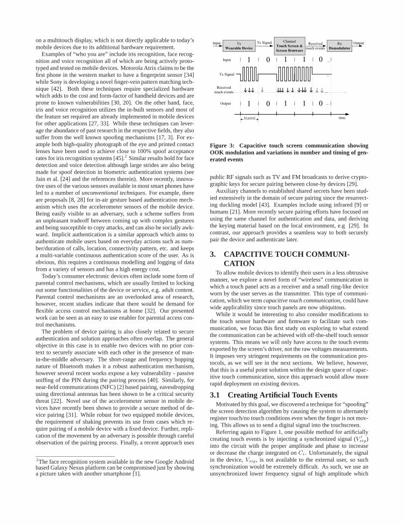
Figure 3: Capacitive touch screen communication showingOOK modulation and variations in number and timing of gen-erated events
public RF signals such as TV and FM broadcasts to derive crypto-graphic keys for secure pairing between close-by devices [29].
Auxiliary channels to established shared secrets have been stud-ied extensively in the domain of secure pairing since the resurrect-ing duckling model [43]. Examples include using infrared [9] orhumans [21]. More recently secure pairing efforts have focused onusing the same channel for authentication and data, and derivingthe keying material based on the local environment, e.g [29]. Incontrast, our approach provides a seamless way to both securelypair the device and authenticate later.
3. CAPACITIVE TOUCH COMMUNI-CATION
To allow mobile devices to identify their users in a less obtrusivemanner, we explore a novel form of “wireless” communication inwhich a touch panel acts as a receiver and a small ring-like deviceworn by the user serves as the transmitter. This type of communi-cation, which we termcapacitive touch communication, could havewide applicability since touch panels are now ubiquitous.
While it would be interesting to also consider modifications tothe touch sensor hardware and firmware to facilitate such com-munication, we focus this first study on exploring to what extendthe communication can be achieved with off-the-shelf touch sensorsystems. This means we will only have access to the touch eventsexported by the screen’s driver, not the raw voltages measurements.It imposes very stringent requirements on the communication pro-tocols, as we will see in the next sections. We believe, however,that this is a useful point solution within the design space of capac-itive touch communication, since this approach would allow morerapid deployment on existing devices.
3.1 Creating Artificial Touch EventsMotivated by this goal, we discovered a technique for “spoofing”
the screen detection algorithm by causing the system to alternatelyregister touch/no touch conditions even when the finger is not mov-ing. This allows us to send a digital signal into the touchscreen.
Referring again to Figure 1, one possible method for artificiallycreating touch events is by injecting a synchronized signal (V ′
sig)into the circuit with the proper amplitude and phase to increaseor decrease the charge integrated onCi. Unfortunately, the signalin the device,Vsig, is not available to the external user, so suchsynchronization would be extremely difficult. As such, we use anunsynchronized lower frequency signal of high amplitude which
Timestamp Event Type Pointer ID(X,Y)
coordinatesTouch Size
Touch
Amplitude
Figure 4: Touch event structure retrieved by touch screen con-troller
charges and dischargesCi asynchronously, leading to repetitive,but irregular, touch/no touch events captured by the touchscreencontroller. This process essentially “spoofs” the touch detectionmechanism by injecting high level repetitive signals and introducesa technique to send a low bit rate signal into the tablet. With pre-cise knowledge of the proprietary touch sensor systems it should bepossible to create much more fine-grained signaling methods. Forthe purpose of this feasibility study, however, we will now considerhow this coarse technique can be leveraged for designing a useridentification system.
3.2 Communication System OverviewThe communication scheme we are proposing can be modeled
as a classical communication system with a transmitter, a receiverand a complex channel connecting the two, as shown in Figure 3.
Transmitter: The transmitter in our system is a wearable battery-powered hardware token. One possible form that such a tokencould take is that of a ring, essentially a digital version of the signetrings carried by nobility in earlier times3. While many other formsof tokens are possible, we will use thering concept as a runningexample throughout the paper.
The ring would contain a small flash memory that stores a bit se-quence or a message, which could be a user identifier or a secret keythat authenticates a user. It also has a simple processor that readsthe bit sequence and generates a On-Off keying (OOK) [15] mod-ulated signal. That is, bitone is represented by turningon a carriersignal; and bitzero by switchingoff that carrier signal, as theTxSignal shown in Figure 3. When the ring is pressed against thescreen, it acts as a voltage source(V ′
sig in figure 1) which createsa set of touch events with timestamps following the bit sequencebeing transmitted.
Channel: Since the events generated follow the bit sequence be-ing transmitted, these events can be used to reconstruct the originalbit sequence, which is unknown to the screen otherwise. Thus, inthis setting, the channel can be thought of as the combination of allhardware and software components that affect the relationship be-tween the transmitted bit sequence and the events registered: (i) theseries of capacitances, (ii) the firmware that comes with the screen,and (iii) the proprietary driver that is a part of the device’s operatingsystem.
Unfortunately, due to the internal switching frequency insidethe touch panel, non-deterministic amount of charge accumulationand the firmware/driver artifacts, the number and the timing of theevents do not directly follow the input sequence. For example, infigure 3, when the first bitone is transmitted, three touch eventsare triggered, while in the succeedingones five and four eventsare produced. Furthermore, even though transmission of azero
should not trigger touch events, one and two events are registeredin the twozeros presented in this example respectively. In addi-tion, the channel adds a variable and unknown delay between thetransmitted sequence and the touch event registered.
Receiver: TheTx Signal transmitted by the ring generates touchevents represented by the 6-tuple structure depicted in Figure 4 (a
3A finger ring bearing a hard-to-fake engraved pattern, whichserves as a seal of authority, a signet.
On-off keying
modulating
Data sequence
(0101011….)
Electrical pulses
Non-volatilely
memory
Signal generator
Amplifier
Electrode
Touch screen controller
Event listener
Demodulator
Capacitive sensors
Voltage differences
Touch events
Touch timestamps, amp...
Applications
Decoded data
Parental control
Multi-user games
ATM authentication
Unlock devices
Logical
Physical
...
Device’s software stack
Wearable device
Transmitter
Receiver
Channel
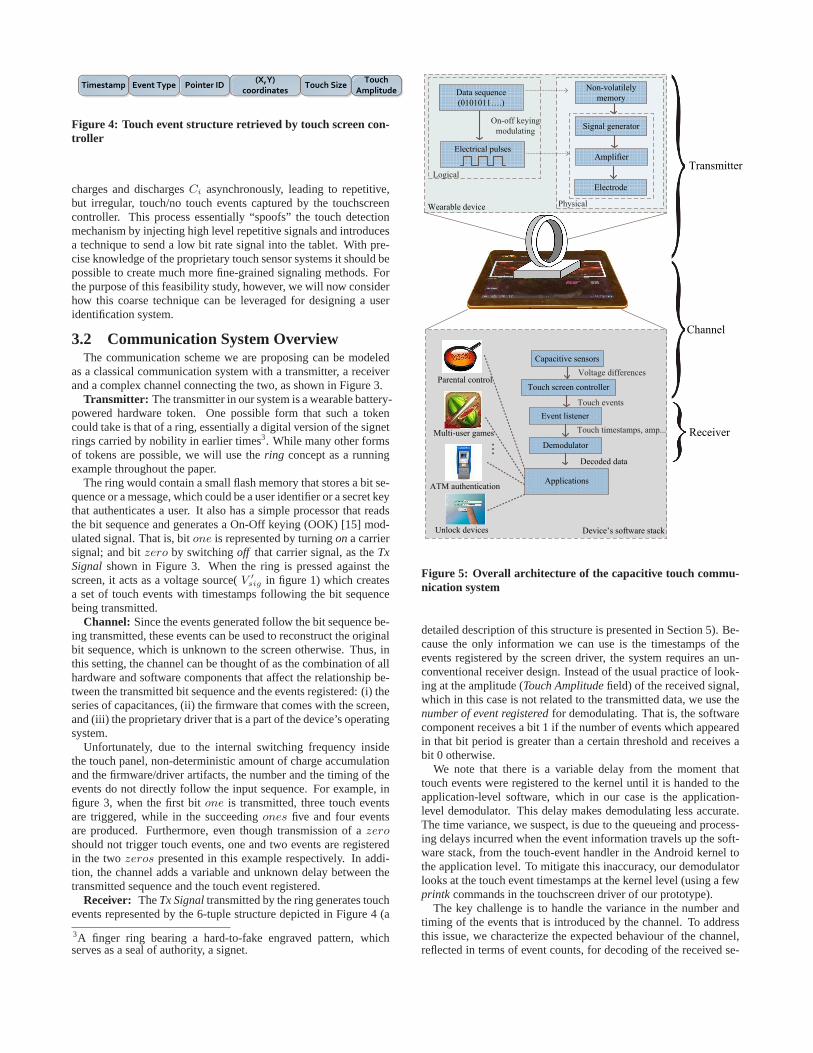
Figure 5: Overall architecture of the capacitive touch commu-nication system
detailed description of this structure is presented in Section 5). Be-cause the only information we can use is the timestamps of theevents registered by the screen driver, the system requires an un-conventional receiver design. Instead of the usual practice of look-ing at the amplitude (Touch Amplitude field) of the received signal,which in this case is not related to the transmitted data, we use thenumber of event registered for demodulating. That is, the softwarecomponent receives a bit 1 if the number of events which appearedin that bit period is greater than a certain threshold and receives abit 0 otherwise.
We note that there is a variable delay from the moment thattouch events were registered to the kernel until it is handed to theapplication-level software, which in our case is the application-level demodulator. This delay makes demodulating less accurate.The time variance, we suspect, is due to the queueing and process-ing delays incurred when the event information travels up the soft-ware stack, from the touch-event handler in the Android kernel tothe application level. To mitigate this inaccuracy, our demodulatorlooks at the touch event timestamps at the kernel level (using a fewprintk commands in the touchscreen driver of our prototype).
The key challenge is to handle the variance in the number andtiming of the events that is introduced by the channel. To addressthis issue, we characterize the expected behaviour of the channel,reflected in terms of event counts, for decoding of the received se-

Bit Rate (bps) 4 5 8 10 12 15Expected no. of 11.3 9.2 5.8 4.5 3.6 3.3
events inones (1e)Expected no. of 2.0 1.6 1.2 1.0 0.7 0.7
events inzeros (0e)One-Zero threshold 7 6 4 4 2 2
Table 1: One-Zero threshold and expected number of events inbit one and zero for different bit rates
quence, as described in Section 4.1. Specifically, we apply a jointdecoding-synchronization technique that uses a threshold-based anddistance-based method to simultaneously synchronize and decodethe received sequence.
Figure 5 shows the high level architecture of the system and howcomponents interact. Note that since we do not have access to thetouchscreen controller, the touch events, not the underlying physi-cal voltage differences, are the input to the receiver.
Indirect Communication: Even without direct contact with thescreen, the ring can communicate with the touchscreen device aslong as the ring bearing finger is in contact with the screen. In par-ticular, the electrical pulses that are transmitted through a humanfinger’s skin from the ring create the same effect of changing thescreen capacitance to register artificial touch events. However, wefound that due to the skin resistance, the number of events gen-erated through this type of indirect contact is only enough for de-tecting the presence of the ring, but not stable and regular enoughfor reliably decoding the data being transmitted. We can leveragethis capability of the communication system to enable a novel tech-nique to differentiate two users simultaneously interacting with thesame touchscreen, for example in a shared-screen two player game.The detection algorithm used for this mode of communication isdescribed in Section 4.3.
4. DECODER DESIGNThe proposed capacitive touch communication system allows
users to send messages to the application layer of the device. Thisunconventional use of the touchscreen, especially under the con-straint of using commercial off-the-shelf devices without lower layeraccess, poses a number of challenges:
1. We observed that the receiver responds differently to the sameinput following a different bit pattern; this could be due ei-ther to the physical layer or the software that is optimized fordetecting touch events from a human finger. For example,the number of events registered to the screen when bit 1 issent after a long sequence of 0s is different from that of a bit1 that comes after a sequence of 1s. The normal solution is tocode the data to avoid this pattern dependent effect. Ratherthan adopting a typical bit-by-bit decoding solution, our datarate is already so limited that we developed our own codeoptimized specifically for the observed pattern dependence.
2. There is a variable delay between the transmission of a sym-bol and its reception at the receiver after processing throughall layers of firmware and software. This jitter significantlyincreases the difficulty of detection. Since the communica-tion channel has low bandwidth and high jitter, no traditionalsymbol synchronization schemes can be directly applied. Weovercome the bit synchronization challenge by simultane-ously synchronizing and demodulating the signal.
3. The channel adds an unknown delay between receiver andtransmitter; this problem is classically solved using a frame
synchronization which requires using a preamble. Since wehave a low bandwidth channel and would like to transmit themessage in only a few seconds, the message can only includelimited number of bits. Thus, we can not afford to add thepreamble. Instead, we use constrained bit patterns that areunique under cyclic shifts caused by unsynchronized frames.
The conversion from touch events to a sequence of binary digitsis based on the principle of On-Off keying; the touchscreen driverproduces several events when a binaryone is transmitted and onlya few events when azero is transmitted. The key challenge is tohandle the variance in the number of events associated withones
and zeros. In the coming sections, we describe an off-line cal-ibration procedure to characterize the expected behaviour of thechannel, which is then used in the online phase to classify touchresponses aszero or one transmissions. Once a sequence of bits isdecoded, we use a “closeness" metric to determine the distance ofthe received message from the set of all possible messages of thesame length. This process corrects for uncertainty in timing andevent number. Details about the design of the closeness metric andthe decoding process are presented in the next sections.
Algorithm 1: Threshold selection algorithminput : Ediscrete - Event sequence in time domain
TxBitSeq - Original transmitted bit sequenceBitRate - Transmission bit rate (bps)
output: 1e and0e - Expected number of events inones andzeros
1 bitPeriod← 1000BitRate
2 oneC← 0 // Event counter for all ones3 zeroC← 0 // Event counter for all zeros4 //Convert discrete events to event vector in time series5 for i = 1→ max(Ediscrete) do6 if exist Ediscrete[j] == i thenEt[i]= 17 elseEt[i] = 0
8 //Find the starting position that gives the max1e0e Ratio9 for startPos =1→bitPeriod do
10 for j =1→ length(TxBitSeq) do11 eCount = sum(Et[startPos + (j− 1) ∗
bitPeriod, startPos + j ∗ bitPeriod])12 if TxBitSeq(j) == 1 then13 oneC = oneC + eCount14 elsezeroC = zeroC + eCount
15 // Update1e0e Ratio16 current1e = oneC/no. bit 1 in TxBitSeq17 current0e = zeroC/no. bit 0 in TxBitSeq18 if current1e/current0e > maxRatio then19 maxRatio = current1e/current0e20 1e =current1e ; 0e= current0e
21 return 1e and0e;
4.1 Determination of Expected Numberof Events for ones and zeros
To determine the number of touch events associated with aone
or zero, it is necessary to calibrate the device at each data rate be-fore use. This calibration to determine thresholds only needs tobe performed once per device, at initialization; thereafter it can bestored in a lookup table and adjusted during self calibration depend-ing on an estimate of the data rate of the incoming data sequenceor fetched as an input from applications. To determine the count-ing threshold for each data rate, a sequence ofones andzeros isrepeatedly transmitted in a prescribed pattern. On the receiver side,event sequence is detected and recorded to a log file. Threshold se-lection algorithm, algorithm 1, takes the log file and the prescribedpattern as input to compute the two expected counter thresholds1e

0 1 2 3 4 5 6 7 8 9 10 11 12 13 140
100
200
300
400
Number of events in one bit
Feq
uenc
y (t
imes
)
bit 0bit 1
Figure 6: Number of events in bit one and bit zero for trans-missions at 4 bits/s
and0e. We devise the algorithm 1 to simultaneously demodulatethe received event sequence and find the bit starting point. The in-tuition behind the algorithm is that the correct bit synchronizationmaximizes total number of events in allones and minimize numberof event in allzeros We define1e0e ratio as being the normalizedratio between thetotal number of events in all ones andtotal num-ber of events in all zeros :
1e0e Ratio =
Σ(Event Counters in Ones)Number of Ones
Σ(Event Counters in Zeros)Number of Zeros
This ratio is maximized when bit synchronization is correct. Theideal synchronization, for example, should have total number ofevents in allzeros close to 0, and number of events in allones
close to the total number of events in the whole event sequence, inwhich case1e0e ratio reaches its maximum.
Algorithm 2: Min Distance Demodulation Algorithminput : Et - Event sequence in time domain
BitRate - Transmission bit rate (bps)MessageLength - Original message lengthPosMessageV ec - Possible message vector1e and0e - Expected number of events in ones and zeros
output: RxBitSeq - Received bit sequence
1 bitPeriod← 1000BitRate
2 minDistance← MAX-INT3 for startPos =1→bitPeriod do4 foreach message in PosMessageV ec do5 rotatedMesgVec =getAllCyclicVersions(message)6 for j =1→MessageLength do7 eCount[j ] = sum(Et[startPos + (j− 1) ∗
bitPeriod, startPos + j ∗ bitPeriod])
8 foreach rotatedInstance in rotatedMesgVec do9 currentDist = 0;
10 foreach ith bit in rotatedInstance do11 if ith bit == 1 then12 currentDist = currentDist + max(0,1e - eCount[i])13 else14 currentDist = currentDist + max(0,eCount[i] - 0e)
15 // Update Min distance16 if currentDistance < minDistance then17 minDistance = currentDist;18 RxCandidate = rotatedInstance;
19 return RxCandidate
Algorithm 1 first converts the discrete timing event informationto a event/no-event time series data. That is, if the received se-quence of event isEdiscrete = E1, E2, ..., Em in which Ei isith event, it will be represented by a vector in the form:Et =[Et1, Et2, ....Ettmax
] whereEti = 1 if there exists an eventEk
such thatEk = i, and0 otherwise. In the second step, the algo-rithm tries all possible bit starting points within the first bit period,with each trial involving a counting of the number of events in allbit periods of the sequence. The starting point that leads to thehighest ratio is considered the correct bit sync position, while thebit sequence corresponding to that starting point is the demodu-lated result of the event sequence. At the end of this process, sincethe total number of events in allones and total number of eventsin all zeros is found, the expected number of events inones andzeros, 1e and0e can be derived and stored in memory for futuredemodulation. Figure 6 shows the distribution of the number oftouch events registered corresponding to the transmissions ofzero
andone evaluated by using algorithm 1 for a 3000 bit sequence ofalternatingzeros andones. The variations due to the transmissionbit rate is recorded in table 1, which shows that the event countthreshold required for decoding varies from 7 events for 4 bits/s to2 events for 15 bits/s.
4.2 Minimum Distance DemodulationUsing the counter thresholds from the previous section, algo-
rithm 2 demodulates the timing event sequence to get the data se-quence sent by the transmitter. Sharing the same synchronizationchallenge with the threshold detection algorithm, this algorithm hasto detect the point in time at which the data is transmitted. At thesame time, it demodulates the event sequence to get the informa-tion that has been transmitted. Note that simply relying on the firstevent to determine the starting point is not enough since there is afair amount of timing uncertainty in the communication channel.Intuitively, the algorithm traverses the sequence to try all possiblestarting points. At each point, it gauges the “distance” betweenthe event sequence and all messages. It then ranks the positionswith “similarity" value and selects the one that has highest “simi-larity" index. The message corresponding to that index will be thedecoded value of the event sequence.
So the question remains as to how to measure the similaritybetween two sequences. We define a distance metric as follow-ing: let D(i, j) be the distance between a event sequence thathas a starting point at pointi and the message,Kj , with j =1..number of messages. Using the same notations as definedin the previous algorithm, in whichEt = [Et1, Et2, ....Ettmax
]is the event vector re-sampled along the time domain, an eventcounter,eCp, for bit at pth position from the starting point canbe computed by:
eCp =
p∗bit period∑
q=(p−1)∗bit period
Etq
Then distanceD(i, j) can be derived as:
D(i, j) =
message length∑
k=1
dk
with
dk =
max(0, eCp − 0e) if the kth bit on messageKj is 0max(0, 1e− eCp) if the kth bit on messageKj is 1
We note that since messages are cyclically transmitted, the algo-rithm does not only compute the distance of a sequence to a mes-sage but it does so for all uniquerotated version of that message.

0 10 20 30
MOVE
AMP
0 10 20 300
5
10
Eve
ntsiz
e
0 10 20 3040
60
80
100
120
Eve
nta
mp
litu
de
0 10 20 30 40
5
10
15
Eve
ntsiz
e
0 10 20 30 4040
60
80
100
120
Eve
nta
mp
litu
de
0 10 20 30 400
MOVE
AMP
(a) Events generated by swipe of a finger without the ring
(b) Events generated by swipe of a finger with the ring
Figure 7: Type, Size and Apmlitude values generated from finger swipes with and without the ring. A ringbearing finger producesmany AMP events while swipe without ring induces correlation betweenSize and Amplitude
The intuition behind this metric is that it rewards starting points thatmake the decoded sequence look similar to one of the messages inthe message vector. The smaller the distance, the closer the de-coded sequence to the message. Hence, smallestD(i, j) will tellwhich position on the sequence is correct synchronization positionand which message is the event sequence representing.
We note that when the number of possible messages is small (or-der of hundreds), it is feasible to apply Algorithm 2 to exhaustivelysearch through the whole message space to demodulate. How-ever, when the number of possible messages is large, the aboveexhaustive algorithm can become prohibitively expensive or impos-sible. In such cases, more efficient algorithm assuming no knowl-edge of the message becomes handy. That algorithm shares thesame intuition with Algorithm 1, in that it tries all possible startingpoints. However, at each possible position, it directly converts thesequence to data bit sequence by counting number of events in eachbit period and select the one that yields the highest1e0e ratio.
Other demodulation schemes. In the process of finding themost suitable demodulation scheme, we experimented with severalother demodulations schemes such asNon-thresholding modula-tion, 1e0e ratio demodulation andmaximum key correlation. Non-thresholding modulation scheme does not require any training tolearn expected number of events in zeros (0e) and ones (1e), insteadit looks at all possible starting positions and compares them withall possible keys to find the best match. It simultaneously picks thesynchronization point and decodes the sequence of events by se-lecting the starting point that gives the highest correlation with oneof the possible keys. The maximum key correlation method takesan approach that is similar to minimum distance modulation but hasa different evaluation function. For that we defined our own corre-lation coefficient function to take the noisy channel into account.The function gives one point to a bit that is equal to the bit at thesame position on the correct key. It gives half a point to the bit thatis not correctly decoded but has a number of events close to theOne − Zero threshold. Lastly,1e0e ratio demodulation becomesuseful when the possible message space is unknown or so largethat it is prohibitively expensive to conduct an exhaustive search tofind minimum distance or maximum correlation. The Min DistanceAlgorithm presented earlier outperformed these techniques in ourexperiments.
4.3 Ring Detection for Indirect Communica-tion
As mentioned in Section 3, an indirect mode of communicationis enabled when instead of the ring, a ring bearing finger is in directcontact with the touchscreen. In such cases, only the presence of aring needs to be detected. However detecting the ring in the pres-ence of finger movements (or finger swipes) is challenging sincethe events generated due to the movement of the finger and thoseby the ring cannot be easily distinguished.
Figure 7 shows three fields of the touch event outputs:Type, SizeandAmplitude, generated when a user swipes a finger across thescreen with and without the ring. We leverage two key observa-tions from the patterns observed for designing a robust detectionalgorithm: (i) events generated by the finger movement without thering are mostly of typeMOVE while those generated by the ring aremostly of typeAMP, however due to the excess pressure exertedfrom the drag force of the finger on the touchscreen, a fewAMPevents can also be generated during finger swipe movements with-out the ring; (ii) in the absence of the ring, the sequence ofSize andAmplitude values are correlated since increasing the pressure bringsmore surface area of the finger in contact with the screen. We con-firm these observations by collecting data from a large number ofswipe movements, both with and without the ring from 5 differentusers.
Since both the presence of a large number ofAMP events andthe absence of correlation betweenSize andAmplitude indicate thepresence of a ring, we define a metricpring, which relates to thenormalized number ofAMP events registered (namp) and the cor-relation coefficient between theSize andAmplitude values (cSA)as:
pring = α× namp + (1− α)× (1− cSA)
whereα ∈ [0, 1] is parameter which signifies the relative contri-butions ofnamp andcSA in determining thepring value. Given aset of generated events, a detection thresholdλth is then used onthepring value to classify the presence or absence of the ring. Wedetermined the values of the two parametersα andλth through atraining set consisting of 1000 swipes from 3 different users, usingtraditional least square minimization. After the training,α andλth
were determined to be 0.83 and 0.5 respectively.

5. EXPLORING THE PARAMETER SPACEData transmission using capacitive touchscreen communication
is an unexplored mode of communication. In this section, we ex-plore the dynamic ranges of frequency, voltage and signal typesthat can be used for triggering usable events through the screendriver. Having picked the most suitable set of parameters, we thenstudy the performance of the communication system for differentuse cases.
In order to conveniently vary the input signal parameters, as re-quired in this analysis, we placed a flat, rounded copper piece onthe screen surface of a Samsung Galaxy Tab 10.1, which uses a At-mel maxTouch touch panel [7], and attached it to the output of aAFG 3000 Series function generator [4]. This setup simulates thetouch of the ring on the screen surface while offering two main ben-efits over the battery-powered prototype described in Section 6: (i)it alleviates the microcontroller’s limitation in generating arbitrarywaveforms and (ii) it greatly expands the scale of repeated experi-ments (order of tens of thousands of logging runs) which would beotherwise limited by time and human effort.
5.1 Triggering Touch EventsThe inner-workings of the touch screen are proprietary and not
available for use in designing either our hardware or software. Amain task is to determine what type of electrical signal will be in-terpreted as a touch event when it is injected into the touchscreen.To answer this, we inject different signals from a function genera-tor through an attached electrode approximately the size of a fingerto the surface of the touchscreen.
The touch events retrieved by the tablet’s operating system, An-droid 3.2, are represented in a 6-tuple structure depicted in Figure 4.Indicated throughEvent Type field, touches are classified into oneof the following types: MOVE, AMP, MOVEAMP, PRESS, RE-LEASE andSUPPRESS. For example, aMOVEAMP event is regis-tered when both touch pressure and X,Y-coordinates change at thesame time; and aSUPPRESS event happens when the touch pres-sure exceeds a predefined threshold. Note that such touch eventsare triggered when a finger first touches the panel, when the posi-tion of the finger on the screen changes, when the pressure changes,and when the finger leaves the screen.Touch Size andTouch Am-plitude specify the size and amplitude of the touch respectively.Pointer ID is used to differentiate the presence of two or morepoints of contact at the same time, or multi-touch. A physicaltouch causes voltage changes at many different electrodes, but the
102
103
104
105
0
5
10
15
20
25
30
35
40
45
Electrical pulse frequency (Hz)
Ave
rage
num
ber
of e
vent
s pe
r se
cond 41.92 events/s
Figure 8: Touchsreen responses to 10 Volt peak-to-peak squarewave signals with different frequencies ranging from 100Hz to120KHz (log scale)
0 2 4 6 8
x 104
0
50
100
150
200
Event sequence number
Inte
r−ev
ent a
rriv
al ti
me
(ms)
Figure 9: Distribution of inter-event arrival times of events gen-erated by a 10 Volt peak-to-peak 1KHz square wave signal cap-tured in kernel level log files
0 20 40 60 80 1000
0.2
0.4
0.6
0.8
1
Inter−event arrival time (ms)
Cum
ulat
ive
dist
ribut
ion
Kernel level logApplication level log
40ms @ 98%
Figure 10: CDF of inter-event arrival times of events capturedat application level and kernel level log files with 10 Volt peak-to-peak 1KHz square wave input signal
firmware and driver aggregate them to output a single touch eventto the operating system. Since the aggregation algorithm is propri-etary, the conversion from electrical signals of our interest to suchtouch events can only be empirically learnt.
An important aspect of the system is the maximum possible datarate through the screen, which depends on two key characteristicsof the screen: (i) the highest rate at which the driver and firmwareallows touch events to be registered and (ii) the internal switchingfrequency of the sensing hardware. Atmel mXT1386’s datasheetspecifies a maximum of 150raw touch events per second [7]. How-ever, due to the driver in Android’s software stack, the maximumrate is significantly reduced. We conducted many experiments togauge the actual maximum event detection rate. We transmit sig-nals with different waveforms, at different frequencies and voltagelevels to a screen. With frequencies ranging from 100 Hz to 120KHz, we observed that a 10 Volt peak-to-peak square wave sig-nal at a frequency of 1 KHz can register the maximum rate of 41events/second (i.e. average inter event arrival time of1
41= 24
ms). In particular, we began with finding the frequency that thetouch-screen was most responsive. To do so, we set the Tektronixdigital function generator to generate square wave of different fre-quencies at 10 Volt peak-to-peak amplitude. The frequency variesfrom 100 Hz to 1 KHz with 100 Hz difference, from 1 KHz to 10KHz with 1KHz difference, and from 10 KHz to 120 KHz with 10s
4 bits/s 5 bits/s 8 bits/s 10 bits/s0
102030405060708090
100D
etec
tion
Rat
e (%
)
2 bits 3 bits 4 bits 5 bits
(a) Detection rate for different message lengths and bit rates
4 bits/s 5 bits/s 8 bits/s 10 bits/s0
1
2
3
4
5
Fal
se A
ccep
tanc
e R
ate
(%)
2 bits 3 bits 4 bits 5 bits
(b) False acceptance rate for different key lengths and bit rates
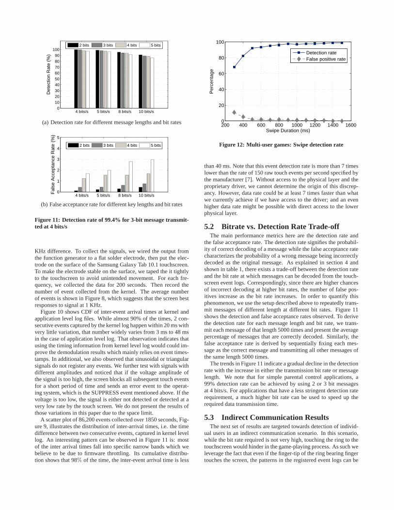
Figure 11: Detection rate of 99.4% for 3-bit message transmit-ted at 4 bits/s
KHz difference. To collect the signals, we wired the output fromthe function generator to a flat solder electrode, then put the elec-trode on the surface of the Samsung Galaxy Tab 10.1 touchscreen.To make the electrode stable on the surface, we taped the it tightlyto the touchscreen to avoid unintended movement. For each fre-quency, we collected the data for 200 seconds. Then record thenumber of event collected from the kernel. The average numberof events is shown in Figure 8, which suggests that the screen bestresponses to signal at 1 KHz.
Figure 10 shows CDF of inter-event arrival times at kernel andapplication level log files. While almost 90% of the times, 2 con-secutive events captured by the kernel log happen within 20 ms withvery little variation, that number widely varies from 3 ms to 48 msin the case of application level log. That observation indicates thatusing the timing information from kernel level log would could im-prove the demodulation results which mainly relies on event times-tamps. In additional, we also observed that sinusoidal or triangularsignals do not register any events. We further test with signals withdifferent amplitudes and noticed that if the voltage amplitude ofthe signal is too high, the screen blocks all subsequent touch eventsfor a short period of time and sends an error event to the operat-ing system, which is the SUPPRESS event mentioned above. If thevoltage is too low, the signal is either not detected or detected at avery low rate by the touch screen. We do not present the results ofthose variations in this paper due to the space limit.
A scatter plot of 86,200 events collected over 1850 seconds, Fig-ure 9, illustrates the distribution of inter-arrival times, i.e. the timedifference between two consecutive events, captured in kernel levellog. An interesting pattern can be observed in Figure 11 is: mostof the inter arrival times fall into specific narrow bands which webelieve to be due to firmware throttling. Its cumulative distribu-tion shows that 98% of the time, the inter-event arrival time is less
200 400 600 800 1000 1200 1400 16000
20
40
60
80
100
Swipe Duration (ms)
Per
cent
age
Detection rateFalse positive rate
Figure 12: Multi-user games: Swipe detection rate
than 40 ms. Note that this event detection rate is more than 7 timeslower than the rate of 150 raw touch events per second specified bythe manufacturer [7]. Without access to the physical layer and theproprietary driver, we cannot determine the origin of this discrep-ancy. However, data rate could be at least 7 times faster than whatwe currently achieve if we have access to the driver; and an evenhigher data rate might be possible with direct access to the lowerphysical layer.
5.2 Bitrate vs. Detection Rate Trade-offThe main performance metrics here are the detection rate and
the false acceptance rate. The detection rate signifies the probabil-ity of correct decoding of a message while the false acceptance ratecharacterizes the probability of a wrong message being incorrectlydecoded as the original message. As explained in section 4 andshown in table 1, there exists a trade-off between the detection rateand the bit rate at which messages can be decoded from the touch-screen event logs. Correspondingly, since there are higher chancesof incorrect decoding at higher bit rates, the number of false pos-itives increase as the bit rate increases. In order to quantify thisphenomenon, we use the setup described above to repeatedly trans-mit messages of different length at different bit rates. Figure 11shows the detection and false acceptance rates observed. To derivethe detection rate for each message length and bit rate, we trans-mit each message of that length 5000 times and present the averagepercentage of messages that are correctly decoded. Similarly, thefalse acceptance rate is derived by sequentially fixing each mes-sage as the correct message and transmitting all other messages ofthe same length 5000 times.
The trends in Figure 11 indicate a gradual decline in the detectionrate with the increase in either the transmission bit rate or messagelength. We note that for simple parental control applications, a99% detection rate can be achieved by using 2 or 3 bit messagesat 4 bits/s. For applications that have a less stringent detection raterequirement, a much higher bit rate can be used to speed up therequired data transmission time.
5.3 Indirect Communication ResultsThe next set of results are targeted towards detection of individ-
ual users in an indirect communication scenario. In this scenario,while the bit rate required is not very high, touching the ring to thetouchscreen would hinder in the game-playing process. As such weleverage the fact that even if the finger-tip of the ring bearing fingertouches the screen, the patterns in the registered event logs can be

Bottom view
Top view
(a) Prototype circuit board (b) Usage of the prototype ring
Figure 13: The prototype ring and its usage for transmitting shortmessages from the ring to a touchpad
used to differentiate between a user with a SigRing and one withoutit.
In order to quantify the performance of this algorithm, we col-lected a total of 6,000 swipes from 3 different users with half theswipes with a ring on. We asked the users to vary the swipe dura-tion between 300ms to 1.5 seconds but since making a swipe lastfor precisely a given time is hard, we bucket the collected swipesinto 100ms durations starting from 250ms to 1550ms and discardswipes outside of this range. The swipe duration of all swipeswithin a bucket are approximated by the mean value of the bucket.Using the move events registered in this dataset, we calculated thedetection rate of ring bearing users and the percentage of swipeswithout rings which were wrongly classified as one with rings, i.e.,the false acceptance rate.
The resulting values shown in Figure 12 shows that the detectionrate increases with the duration of the swipe, at first sharply from∼68% for 300ms swipes to∼92% for 500ms swipes and then grad-ually after that. Thus if the swipes used in a multi-player game ismore than 700ms, the users can be classified correctly with a 95%confidence level.
6. RING PROTOTYPE AND EVALUATIONThe use of this communication channel with touchscreen device
requires a hardware token to generate the appropriate electrical sig-nal and inject it into the touch sensing circuitry. In this section, wedescribe our prototype of the ring which uses off-the-shelf compo-nents.
6.1 Hardware PrototypeThe core of the token is the low cost, low power microprocessor,
TI-MSP430F2722 [35] that was programmed to generate modu-lated 3 Volt square waves at a frequency of 1KHz. Figure 14 showsthe schematic of the custom-built ring. This square wave is mod-ulated with On-Off keying to trigger artificial touch events in thescreen’s firmware. The microprocessor is mounted on a 18 mmx 30 mm off-the-shelf board, part of TI-MSP430 eZ430 develop-ment kit, as shown on Figure 13(a)-bottom view. We specify thetransmission data rate and data sequence by programming the mi-croprocessor through the USB interface that comes with the kit.The square wave and its parameters were selected through exper-iments with a function generator, as described in section 5. Since
9V
E
CB
TI-MSP430
F2722
Ring Surface
30pF
560 Ω
180 Ω
Figure 14: Schematic of the custom-built ring
we found that 3 Volt was not adequate for generating touch events,we amplify the output of the microprocessor using a single bipolartransistor, BC548B [5], with the supply voltage of 9 Volt (Figure13(a)-top view). One of the most challenging parts of the proto-type was to design the electrode configuration that would allow thesignal to be injected in series with the touchscreen and the bodycapacitance of the user. The best point in the circuit to inject thesignal,V ′
sig in figure 1, would be in series with the finger and therest of the body at a point close to the screen. This has obviousanatomical difficulties and the low internal resistance of the bodymakes injection between two closely spaced electrodes, as on theinside surface of a ring, impractical. We opted for a system wherethe user would wear an insulating ring whereV ′
sig was injected be-tween electrodes on the inside and outside of the dielectric band.The inner electrode was connected with the finger and, through thebody capacitanceCB and case capacitanceCc (as described in sec-tion 2), to the internal circuitry in the tablet. The outer electrode onthe ring was directly pressed on the screen, formingCs to completethe circuit.
Because a uniform and reproducible contact between the touch-screen and the ring is essential to minimize the error rate, we chooseto use a flexible conductive material to make the electrode and de-sign the face of the ring to control the compression of that material.If the pressure is too high, the screen bends and its capacitance,Cs,increases which in turns can introduce errors. We control this pres-sure by surrounding the electrode with an insulating spacer of the

4 bits/s 5 bits/s0
10
20
30
40
50
60
70
80
90
100
Det
ectio
n R
ate
(%)
2 bits 3 bits 4 bits 5 bits
(a) Detection rate
4 bits/s 5 bits/s0
0.5
1
1.5
2
Fal
se A
ccep
tanc
e R
ate
(%)
2 bits 3 bits 4 bits 5 bits
(b) False acceptance rate
Figure 15: Detection rate and False acceptance rate using ringprototype for different message lengths and bit rates
correct thickness to properly control the compression of the flexibleelectrode.
6.2 Preliminary Prototype PerformanceUsing the prototype ring, we experimented with injecting mes-
sages through the Samsung Galaxy Tablet 10.1 touchscreen. Whileconducting the experiment, we noticed that at times no events weretriggered during the transmission of a 1 bit or vice versa. This leadto unreliable decoding of messages but we were still able to distin-guish two codes with a larger hamming distance. We used one ringwith the code ’1110’ and one ring with the code ’1000’ and touchedeach of the 50 times on the tablet display. A simple threshold algo-rithm that uses as input the number of touchscreen events generatedwas able to identify the first ring correctly 44 times and the secondring 43 times, leading to an overall detection rate of 87%. We sus-pect that the quality of the contact between the ring and the touchpanel plays a critical role in these experiments.
To eliminate this variance due to contact differences from touchto touch, we experimented with transmitting multiple messageswhile the ring was held steady on the display. Here, we used mes-sage lengths between 2 and 5 bits transmitted at the rates of 4 bits/sand 5 bits/s from which the detection rate (DR) and false accep-tance rate (FAR) are evaluated. For each message at each data rate,we put the ring down onto the screen 3 times and keep it there longenough so that 200 repetitions of the message are transmitted fromthe ring to the screen. We show in Figure 15 the DR and FARresults over the 200 repetitions from best case (presumably bestcontact) of these three trials. Each bar represents the average ratesover different data rates and message lengths. We observed thatthe detection rate decreases with the increase of both the messagelength and bit rate. Note, however, that the overall detection ratecould be improved through retransmissions of the message. There-fore, even the lower detection rate of 82% may still be adequatefor some of our targeted applications. For the user identificationapplication, for example, up to 3 seconds of continuous repeated
message transmission would results in less than 6 errors per 1000uses. These results illustrate what can be achieved with this trans-mitter if the reliability issues are worked out.
We believe that another source of error in this prototype stemsfrom the relatively long rise time of the square wave since thetouchscreen events appear to be triggered by the edges in the in-put signal. It is also important to note that both the electronics andthe firmware of the screen, which we do not have access to, are op-timized for the relatively slow movement of a human finger. Thus,the screen driver deliberately throttles the maximum rate of touchevents, which reduces touch error in normal use but limits our sys-tem to very low bit rate transmission. We believe that the transmis-sion rate could be improved substantially with access to the touch-screen controller firmware, which should allow processing internaltouchscreen measurements, e.g. physical voltage differences.
7. DISCUSSIONLet us briefly consider several remaining issues related to the
energy consumption and security applications of this technique.Energy Consumption. The current prototype implementation
is based on a 3 Volt microprocessor driving a 9 Volt high speedbipolar transistor amplifier to generate a continuous signal. Energyconsumption and some of the synchronization issues in our proto-type could be significantly reduced by incorporating a switch underthe contact surface that powers up the ring when pressed against thetouch screen. To estimate the cost and battery life of such a ring ver-sion, we use the smallest readily available lithium primary battery,the CR2025 which is 10 mm diameter and supplies 3.0 volts with a30 mA-h capacity. The typical current drain in standby with RAM-retention of a modern microprocessor (e.g. the TI MSP430 family)is about 0.1 microamps. Even with this small battery, this wouldprovide over 3 decades of standby lifetime for the ring electron-ics. Once awake, the processor will use significantly more current,but the minimal computing requirements result in this being low,also. The smaller MSP-430 processors typically use about 220 mi-croamp at 1 MHz, so even if shifting out the short code takes 100cycles of the CPU, this battery will still provide enough energy forover 5000 uses.
Since the capacitances are very small, the current also will below and a simple buck-boost dc-dc converter with one miniatureinductor will be quite adequate to supply the 9 Volt[6]. Assumingonly a 10% charge conversion efficiency for the converter, this cir-cuit still uses only about 2 nanocouloumbs/charge-discharge cycle.Modulating at 1 KHz and sending 10 bits/second, this allows thebattery to supply over 50 million bits, far in excess of any of theother limits in the system. The cost of such a system will be domi-nated by the processor, several tens of cents, but in high volume thatcan be replaces by a simple sequence generator, either read-only orflash, for only a few cents.
Security considerations. The current limits on datarate onlyallow transmission of very short codes and thus allow only weakauthentication at best. Improvements in datarate through modifica-tions in the touchscreen firmware could alleviate these limits, how-ever. The low carrier frequency of our system, between 5-10 kHz,would then also offers additional protection against eavesdropping.Since antenna size should be proportional to the wavelength of thesignal, transmission of this signal into the RF domain would requirean antenna much larger than the size of the human body. While wecannot rule out that some signal can be received with customizedresonant antennas, however, the level of effort required would bemuch higher than for picking up a e.g. 2.4 GHz signal used in WiFiand Bluetooth. If such eavesdropping ever were an issue, it could

also be addressed by transmitting a noise signal from the receivingdevice.
Finally, the design could be enhance with a feedback channel us-ing a photodetector. The ring could receive information from themobile device through this visual channel, where the device en-codes the information in the pixel intensities. This would enable achallenge response protocol, which could greatly enhance the se-curity of an authentication system.
8. CONCLUSIONWe have presented the design and implementation of a tech-
nique to transmit information through a capacitive touchscreen.Our method triggers touch events in the touchscreen device by in-jecting an electric signal that affects the capacitance measurementsof the screen. Our experiments show that this is feasible evenwith an off-the-shelf touchscreen system, albeit at very low bitrates.Controlled experiments with a signal generator demonstrates datarates of 5-10 bps. While some reliability challenges remains, wealso achieved up to 4-5 bps with a wearable transmitter token inthe form of a small signet ring and demonstrated that some signalscan be transmitted through the human skin. Transmission of infor-mation via small physical tokens can be used to distinguish whois interacting with a mobile device, and can be useful for parentalcontrol, multiuser games (particularly when played on a single de-vice), and possibly play a role in authentication solutions. It differsfrom other short-range communication systems in that it requiresphysical touch for communication, which can be an advantage ifmultiple potential users are so close that they cannot be differenti-ated with the other short-range systems. The technique could alsobe used to distinguish different devices touching the screen such asstyluses or boardgame tokens. We believe that significantly higherdata rates could be achieved by designing receiver capabilities intotouch screens and few this work as a first step towards exploringhow this touch sensor can participate in the exchange of informa-tion between mobile devices.
AcknowledgementWe are thankful to Nilanjan Paul, Joshua Devasagayaraj, and IvanSeskar for their help with developing prototypes of the signet ring.This material is based in part upon work supported by the NationalScience Foundation under Grant Nos. 0845896 and 1040735. Anyopinions, findings, and conclusions or recommendations expressedin this material are those of the authors and do not necessarily re-flect the views of the National Science Foundation.
9. REFERENCES[1] Face recognition on galaxy nexus is very neat, but easily compromised with the
picture? http://tiny.cc/gj50gw, 2011.[2] Nearfield communications forum. http://www.nfc-forum.org/, 2011.[3] A. Adler. Vulnerabilities in biometric encryption systems. InProc. of AVBPA,
2005.[4] Afg3000 series arbitrary function generators. http://www.tek.com/AFG3000.[5] Amplifier transistors bc548b. http://onsemi.com.[6] An mcu-based buck-boost converter for battery chargers. http://www.st.com/.[7] Atmel maxtouch mxt1386 specifications.
http://www.atmel.com/devices/MXT1386.aspx.[8] G. Bailador, C. Sanchez-Avila, J. Guerra-Casanova, and A. de Santos Sierra.
Analysis of pattern recognition techniques for in-air signature biometrics.Pattern Recognition, 44(10-11):2468 – 2478, 2011.
[9] D. Balfanz, D. K. Smetters, P. Stewart, and H. C. Wong. Talking to strangers:Authentication in ad-hoc wireless networks. InProc. of NDSS, Feb. 2002.
[10] Belkin. Wemo home automation system.[11] N. Ben-Asher, N. Kirschnick, H. Sieger, J. Meyer, A. Ben-Oved, and S. Möller.
On the need for different security methods on mobile phones. InProc. ofMobileHCI, Aug. 2011.
[12] H. Bojinov and D. Boneh. Mobile token-based authentication on a budget. InProc. of HotMobile, Feb. 2011.
[13] Craftsman. Assurelink garage doors openers.[14] P. Dietz and D. Leigh. Diamondtouch: a multi-user touch technology.In Proc.
of UIST, Nov. 2001.[15] Digital Modulation Schemes.
http://robotics.eecs.berkeley.edu/ sastry/ee20/modulation/node5.html.[16] P. Dunphy, A. P. Heiner, and N. Asokan. A closer look at recognition-based
graphical passwords on mobile devices. InProc. of SOUPS, July 2010.[17] M. Faundez-Zanuy. On the vulnerability of biometric security systems.
Aerospace and Electronic Systems Magazine, IEEE, 19(6):3 – 8, June 2004.[18] C. Foresman. Apple facing class-action lawsuit over kids’ in-app purchases. Ars
Technica, Apr. 2011.[19] Fundamentals of electrostatic discharge.
http://www.esda.org/fundamentalsp5.html, 2010.[20] J. Galbally-Herrero, J. Fierrez-Aguilar, J. D. Rodriguez-Gonzalez,
F. Alonso-Fernandez, J. Ortega-Garcia, and M. Tapiador. On the vulnerabilityof fingerprint verification systems to fake fingerprints attacks. InProc. ofCarnahan Conferences on Security Technology, Oct. 2006.
[21] C. Gehrmann, C. J. Mitchell, and K. Nyberg. Manual authentication forwireless devices.CryptoBytes, Spring 2004.
[22] E. Haselsteiner and K. Breitfuss. Security in Near Field Communication (NFC).In Proc. of the Workshop on RFID Security, 2006.
[23] K. Hawkey and K. M. Inkpen. Examining the content and privacy of webbrowsing incidental information. InProc. of WWW, May 2006.
[24] A. K. Jain, K. Nandakumar, and A. Nagar. Biometric template security.EURASIP J. Adv. Signal Process, 2008:113:1–113:17, Jan. 2008.
[25] E. A. Johnson. Touch Displays: A Programmed Man-Machine Interface.Ergonomics, 10(2):271–277, 1967.
[26] A. K. Karlson, A. B. Brush, and S. Schechter. Can i borrow your phone?:understanding concerns when sharing mobile phones. InProc. of CHI, Apr.2009.
[27] S. Kurkovsky, T. Carpenter, and C. MacDonald. Experiments with simpleirisrecognition for mobile phones. InProc. of Information Technology: NewGenerations, pages 1293 –1294, april 2010.
[28] J. Liu, L. Zhong, J. Wickramasuriya, and V. Vasudevan. User evaluationoflightweight user authentication with a single tri-axis accelerometer. InProc. ofMobileHCI, Sept. 2009.
[29] S. Mathur, R. Miller, A. Varshavsky, W. Trappe, and N. Mandayam. Proximate:proximity-based secure pairing using ambient wireless signals. InProc. ofMobiSys, June 2011.
[30] T. Matsumoto, H. Matsumoto, K. Yamada, and S. Hoshino. Impact of Artificial"Gummy" Fingers on Fingerprint Systems. InProc. of SPIE Vol. 4677, 2002.
[31] R. Mayrhofer and H. Gellersen. Shake well before use: Intuitive and securepairing of mobile devices.IEEE TMC, 8(6):792 –806, Jun. 2009.
[32] M. L. Mazurek, J. P. Arsenault, J. Bresee, N. Gupta, I. Ion, C. Johns, D. Lee,Y. Liang, J. Olsen, B. Salmon, R. Shay, K. Vaniea, L. Bauer, L. F. Cranor, G.R.Ganger, and M. K. Reiter. Access control for home data sharing: Attitudes,needs and practices. InProc. of CHI, May 2010.
[33] Mobile biometry: European funded project (fp7-2007-ict-1).http://www.mobioproject.org/, 2011.
[34] Motorola atrix: Technical specifications. http://bit.ly/f7nfEX, 2011.[35] Msp430 ultra-low power 16-bit microcontrollers. http://msp430.com.[36] A. Nicholson, M. D. Corner, and B. D. Noble. Mobile Device Security using
Transient Authentication.IEEE TMC, 5(11):1489–1502, November 2006.[37] Ringbow. http://ringbow.com/ringbow/.[38] V. Roth, P. Schmidt, and B. Güldenring. The IR ring: authenticating users’
touches on a multi-touch display. InProc. of UIST, Oct. 2010.[39] M. Sato, I. Poupyrev, and C. Harrison. Touche: enhancing touch interaction on
humans, screens, liquids, and everyday objects. InProc. of CHI, pages483–492, New York, NY, USA, 2012.
[40] Y. Shaked and A. Wool. Cracking the bluetooth pin. InProc. of MobiSys, pages39–50, 2005.
[41] E. Sofge. Can a smartphone make your car smarter?MSN Autos, 2010.[42] Sony - mofiria finger-vien pattern recognition. http://bit.ly/cIHGuj, 2009.[43] F. Stajano and R. J. Anderson. The resurrecting duckling: Security issues for
ad-hoc wireless networks. InProc. of Security Protocols, Apr. 2000.[44] Technology review article: Pushing the limits of the touch screen, 2011.[45] L. Thalheim and J. Krissler. Body check: Biometric access protection devices
and their programs put to the test.ct Magazine, Nov. 2002.[46] M. Weir, S. Aggarwal, M. Collins, and H. Stern. Testing metrics for password
creation policies by attacking large sets of revealed passwords. InProc. of CCS,Oct. 2010.
[47] W. Westerman and J. G. Elias. US 0232567 Patent - Capacitive SensingArrangment, 2006.