distillation columndistillation...
TRANSCRIPT
Distillation ColumnDistillation ColumnDistillation ColumnDistillation Column

Distillation:
“Process in which a liquid or vapour mixture of two or more substances is separated into its component fractions of desired purity, by the application and removal of heat”

CHOICE BETWEEN PLATE AND PACKED COLUMN
The choice between use of tray column or a packed column for a given mass transfer operation should, theoretically, be based on a detail cost analysis for the two types of contactors. However, the decision can be made on the basis of a qualitative analysis of relative advantages and disadvantages, eliminating the need for a detailed cost comparison.
Which are as follows
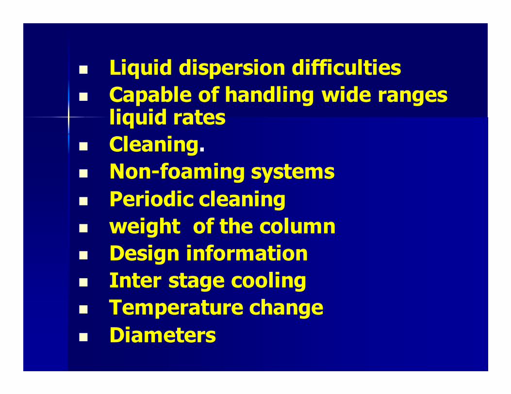
� Liquid dispersion difficulties
� Capable of handling wide ranges liquid rates
� Cleaning.
� Non-foaming systems
� Periodic cleaning
� weight of the column
� Design information
� Inter stage cooling
� Temperature change
� Diameters
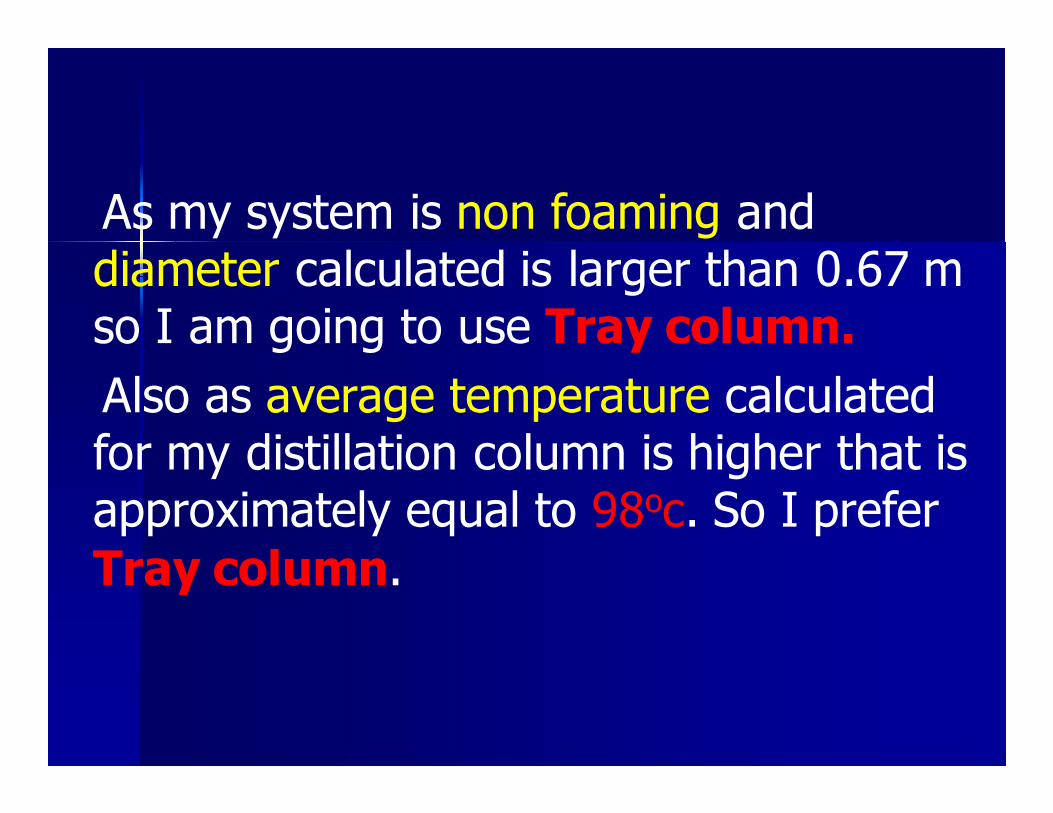
As my system is non foaming and diameter calculated is larger than 0.67 m so I am going to use Tray column.
Also as average temperature calculated for my distillation column is higher that is approximately equal to 98oc. So I prefer
Tray column.

PLATE CONTACTORS:
Cross flow plate are the most commonly used plate contactor in distillation. In which
liquid flows downward and vapours flow upward. The liquid move from plate to plate via down comer. A certain level of liquid is
maintained on the plates by weir.

Three basic types of cross flow trays used are
� Sieve Plate (Perforated Plate)
� Bubble Cap Plates
� Valve plates (floating cap plates)

Selection of Trays:
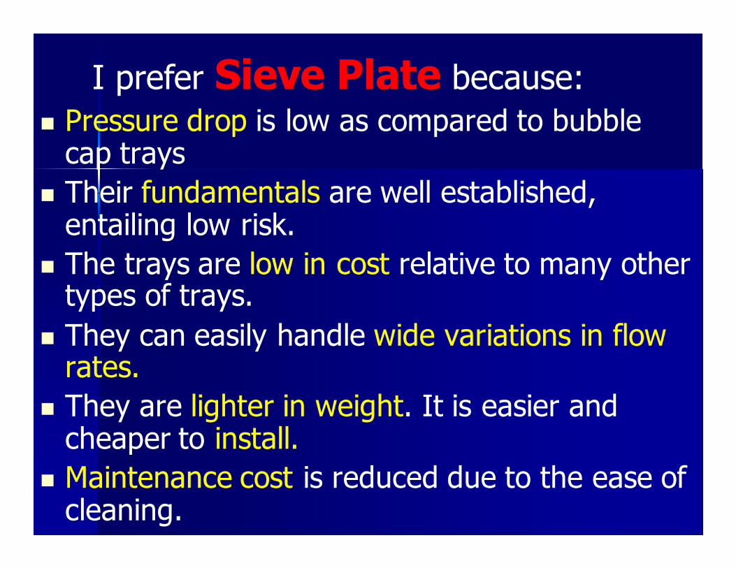
I prefer Sieve Plate because:
� Pressure drop is low as compared to bubble cap trays
� Their fundamentals are well established, entailing low risk.
� The trays are low in cost relative to many other types of trays.
� They can easily handle wide variations in flow rates.
� They are lighter in weight. It is easier and cheaper to install.
� Maintenance cost is reduced due to the ease of cleaning.
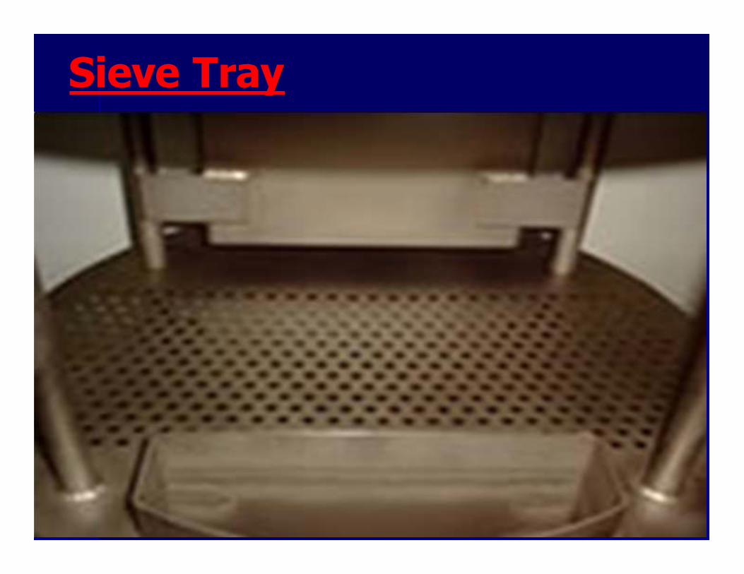
Sieve Tray
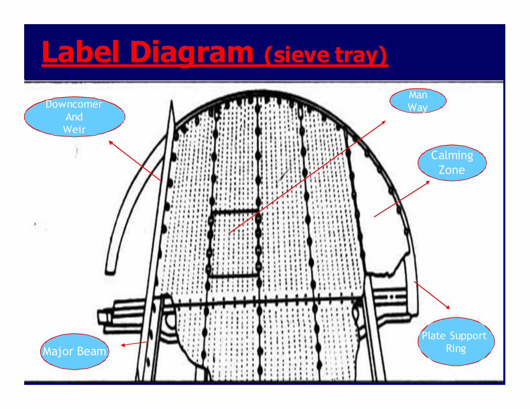
Label Diagram (sieve tray)
Major Beam
Plate Support
Ring
Downcomer
And
Weir
Calming
Zone
Man
Way

FACTORS AFFECTING DISTILLATION COLUMN OPERATION
Adverse vapour flow conditions can cause:
� Blowing
� Coning
� Dumping
� Raining
� Weeping
� Flooding

FEED
REFLUX
DRUM
(1) Methyl Iodide = 0.074
(2) Acetic Acid = 0.65
(3)Methyl Acetate = 0.215
(4) Water = 0.065
(1) Methyl Iodide
= 0.212
(2) Acetic Acid =
0.0005
(3)Methyl
Acetate = 0.62
(4) Water = 0.167
Condenser
Pump
Reboiler
FEED
(1) Methyl Iodide = 0.07
(2) Acetic Acid = 0.65
(3)MethylAcetate=0.22
(4) Water = 0.065
REFLUX DRUM
(1) Methyl Iodide = 0.21
(2) Acetic Acid = 0.0005
(3)Methyl Acetate = 0.62
(4) Water = 0.17
(1)Acetic Acid = 0.99
(2)Water = 0.01
FLOW SHEET
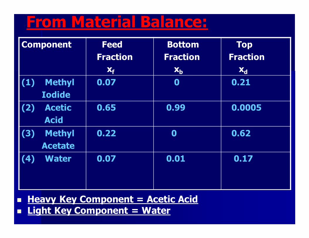
From Material Balance:
� Heavy Key Component = Acetic Acid � Light Key Component = Water
Component Feed
Fraction
xf
Bottom
Fraction
xb
Top
Fraction
xd
(1) Methyl
Iodide
0.07
0
0.21
(2) Acetic
Acid
0.65
0.99 0.0005
(3) Methyl
Acetate
0.22
0
0.62
(4) Water
0.07
0.01
0.17
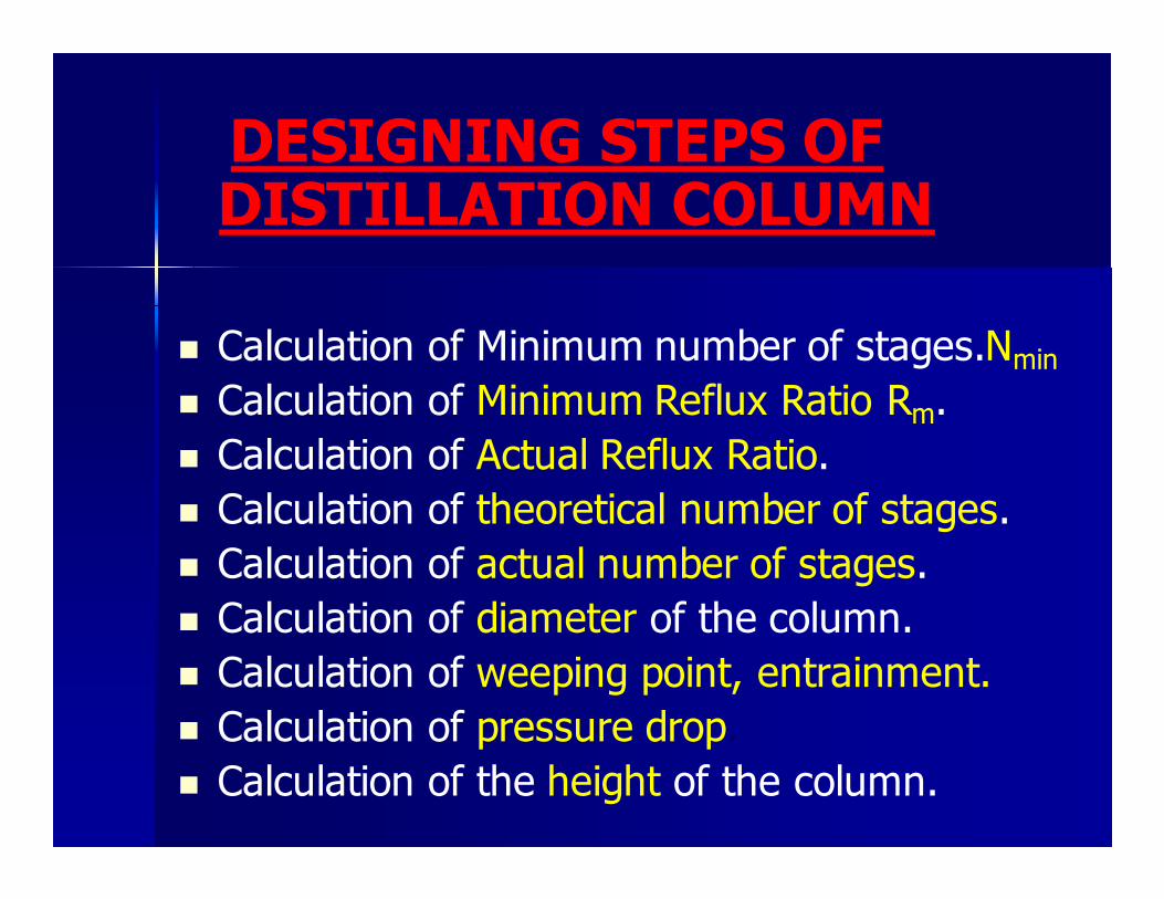
DESIGNING STEPS OF DISTILLATION COLUMN
� Calculation of Minimum number of stages.Nmin
� Calculation of Minimum Reflux Ratio Rm.
� Calculation of Actual Reflux Ratio.
� Calculation of theoretical number of stages.
� Calculation of actual number of stages.
� Calculation of diameter of the column.
� Calculation of weeping point, entrainment.
� Calculation of pressure drop.
� Calculation of the height of the column.
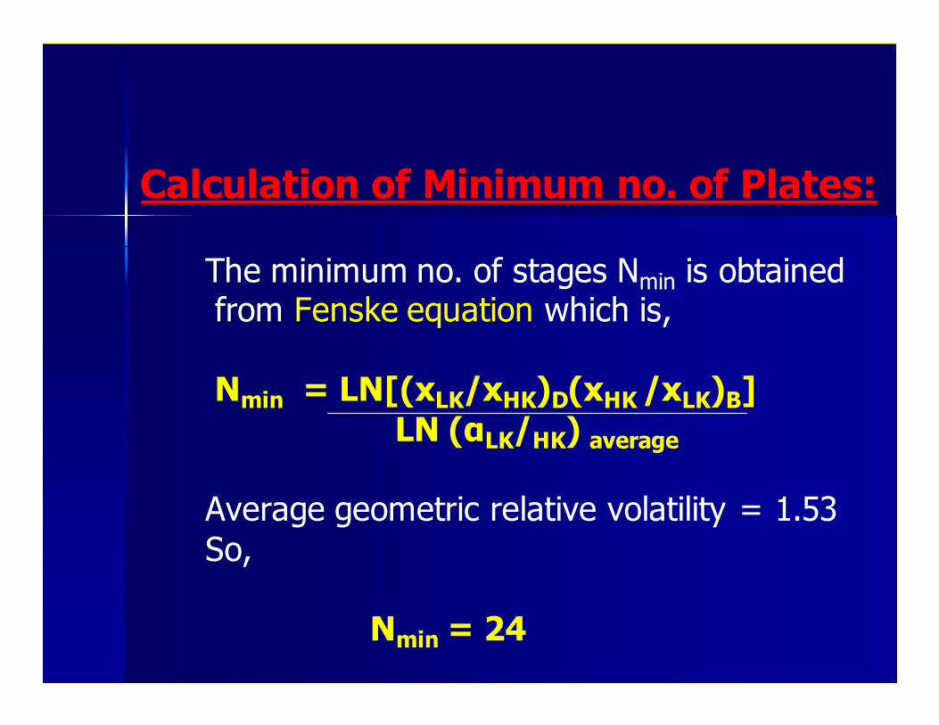
Calculation of Minimum no. of Plates:
The minimum no. of stages Nmin is obtained from Fenske equation which is,
Nmin = LN[(xLK/xHK)D(xHK /xLK)B]
LN (αLK/HK) average
Average geometric relative volatility = 1.53
So,
Nmin = 24
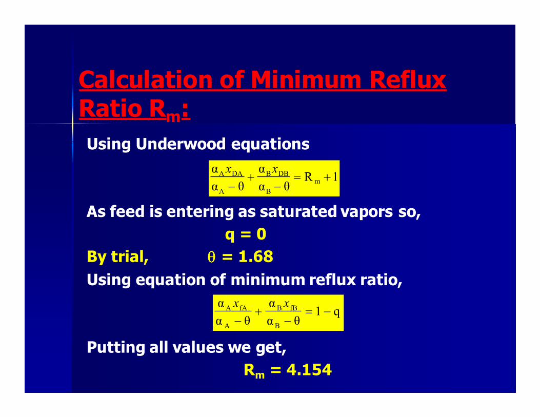
Calculation of Minimum Reflux Ratio Rm:
Using Underwood equations
As feed is entering as saturated vapors so,
q = 0
By trial, θθθθ = 1.68
Using equation of minimum reflux ratio,
Putting all values we get,
Rm = 4.154
1Rθα
α
θα
αm
B
DBB
A
DAA +=−
+−
xx
q1θα
α
θα
α
B
fBB
A
fAA −=−
+−
xx

Actual Reflux Ratio:
The rule of thumb is:
R = (1.2 ------- 1.5) R min
R = 1.5 R min
R = 6.23

Theoretical no. of Plates:
Gilliland related the number of equilibrium stages and the minimum reflux ratio and the no. of equilibrium stages with a plot that was transformed by Eduljee into the relation;
From which the theoretical no. of stages to be,
N= 39
+−−=+
−566.0
minmin
1175.0
1 RRR
NNN

Calculation of actual number of stages: Overall Tray Efficiency:
−= avgavgoE αµ .log5.3251
α avg =average relative volatility of light key component
=1.75
µ avg = molar average liquid viscosity of feed evaluated at
average temperature of column
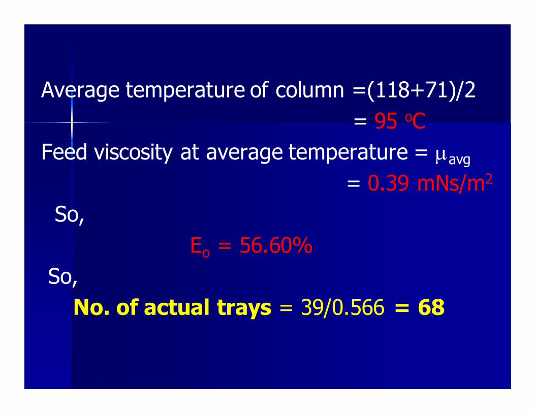
Average temperature of column =(118+71)/2
= 95 oC
Feed viscosity at average temperature = µavg
= 0.39 mNs/m2
So,
Eo = 56.60%
So,
No. of actual trays = 39/0.566 = 68
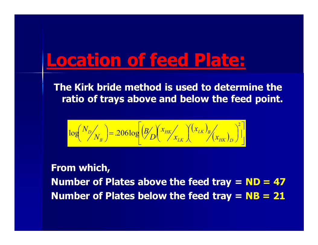
Location of feed Plate:
The Kirk bride method is used to determine the ratio of trays above and below the feed point.
From which,
Number of Plates above the feed tray = ND = 47
Number of Plates below the feed tray = NB = 21
( ) ( )( )
=
2
log206.logDHK
BLK
LK
HK
B
D
xx
xx
DB
NN
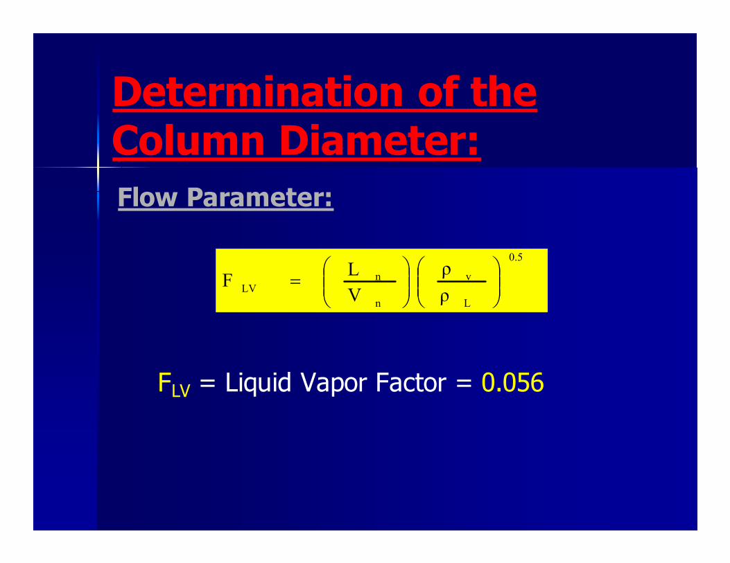
Determination of the Column Diameter:
Flow Parameter:
FLV = Liquid Vapor Factor = 0.056
0.5
L
v
n
nLV
ρ
ρ
V
LF
=

Capacity Parameter:
Assumed tray spacing = 18 inch (0.5 m)
From Fig (15-5) Plant Design and Economics for Chemical Engineering, sieve tray flooding capacity,
Csb = 0.0760 m/Sec Surface tension of Mixture = σ = 18.35 dynes/Cm
Vnf=1.67 m/sec
Assume 90% of flooding then Vn=0.9Vnf
So, actual vapor velocity, Vn=1.51 m/sec
5.02.0
20
−
=v
vlCV sbnf ρ
ρρσ

Net column area used in separation is
An = mv/Vn
Volumetric flow rate of vapors = mv
mv = (mass vapor flow rate /(3600)
vapor density)
mv = 2.1184m3/sec
Now, net area An = mv/Vn = 1.41m2
Assume that downcommer occupies 15% of cross sectional Area (Ac) of column thus:
Ac = An + Ad
Where, Ad = downcommer area
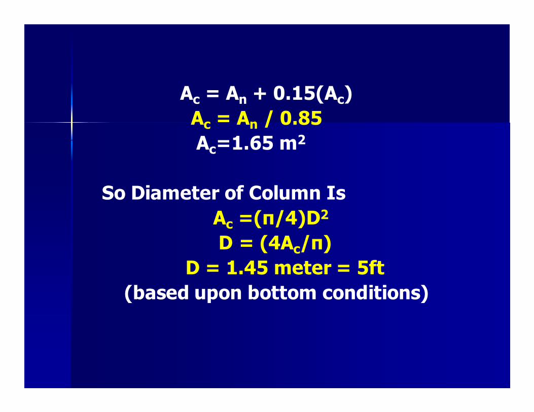
Ac = An + 0.15(Ac)
Ac = An / 0.85
Ac=1.65 m2
So Diameter of Column Is
Ac =(π/4)D2
D = (4Ac/π)
D = 1.45 meter = 5ft
(based upon bottom conditions)
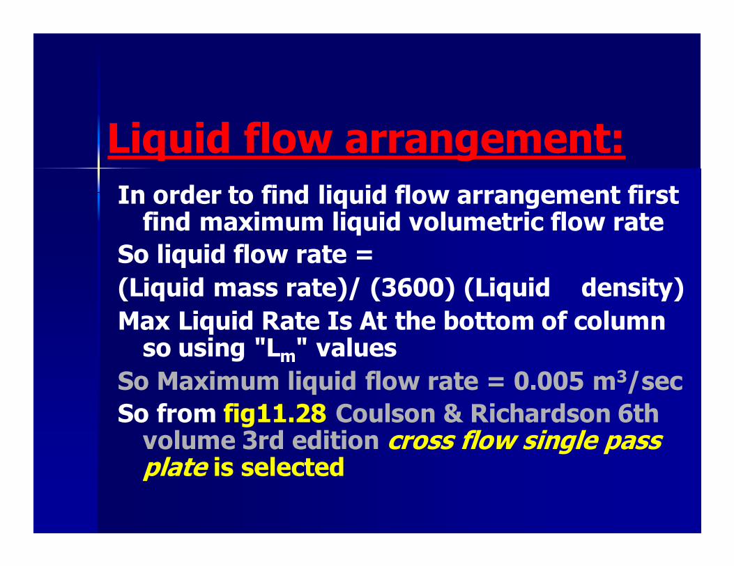
Liquid flow arrangement:
In order to find liquid flow arrangement first find maximum liquid volumetric flow rate
So liquid flow rate =
(Liquid mass rate)/ (3600) (Liquid density)
Max Liquid Rate Is At the bottom of column so using "Lm" values
So Maximum liquid flow rate = 0.005 m3/sec
So from fig11.28 Coulson & Richardson 6th volume 3rd edition cross flow single pass plate is selected
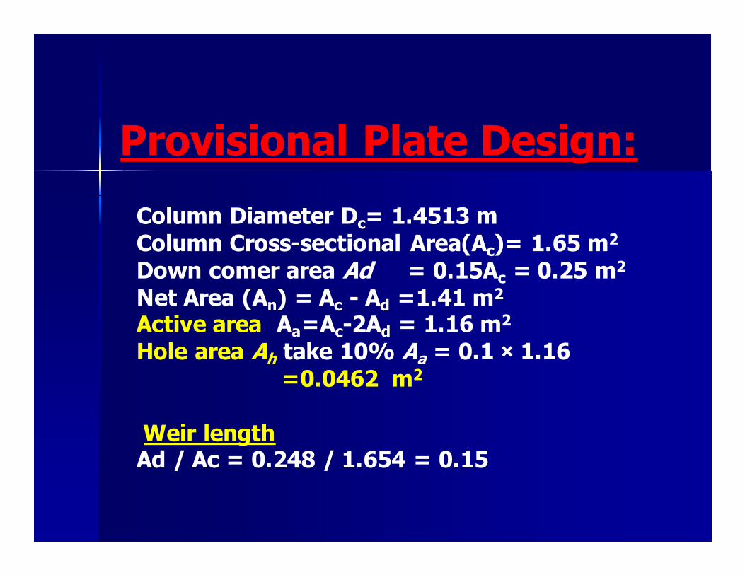
Provisional Plate Design:
Column Diameter Dc= 1.4513 m Column Cross-sectional Area(Ac)= 1.65 m2
Down comer area Ad = 0.15Ac = 0.25 m2
Net Area (An) = Ac - Ad =1.41 m2
Active area Aa=Ac-2Ad = 1.16 m2
Hole area Ah take 10% Aa = 0.1 × 1.16 =0.0462 m2
Weir length Ad / Ac = 0.248 / 1.654 = 0.15

From figure 11.31 Coulson & Richardson 6th volume 3rd edition
Lw / dc = 0.80
Lw = 1.452*0.80 = 0.733 m Weir length should be 60 to 85% of
column diameter which is satisfactory
Take weir height, hw= 50 mm Hole diameter, dh = 5 mm Plate thickness = 5 mm
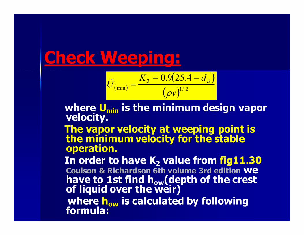
Check Weeping:
where Umin is the minimum design vapor
velocity. The vapor velocity at weeping point is
the minimum velocity for the stable operation.
In order to have K2 value from fig11.30 Coulson & Richardson 6th volume 3rd edition we have to 1st find how(depth of the crest of liquid over the weir)
where how is calculated by following formula:
( )( )
( ) 2/1
2
min
4.259.0
v
dKU h
ρ
−−=
(
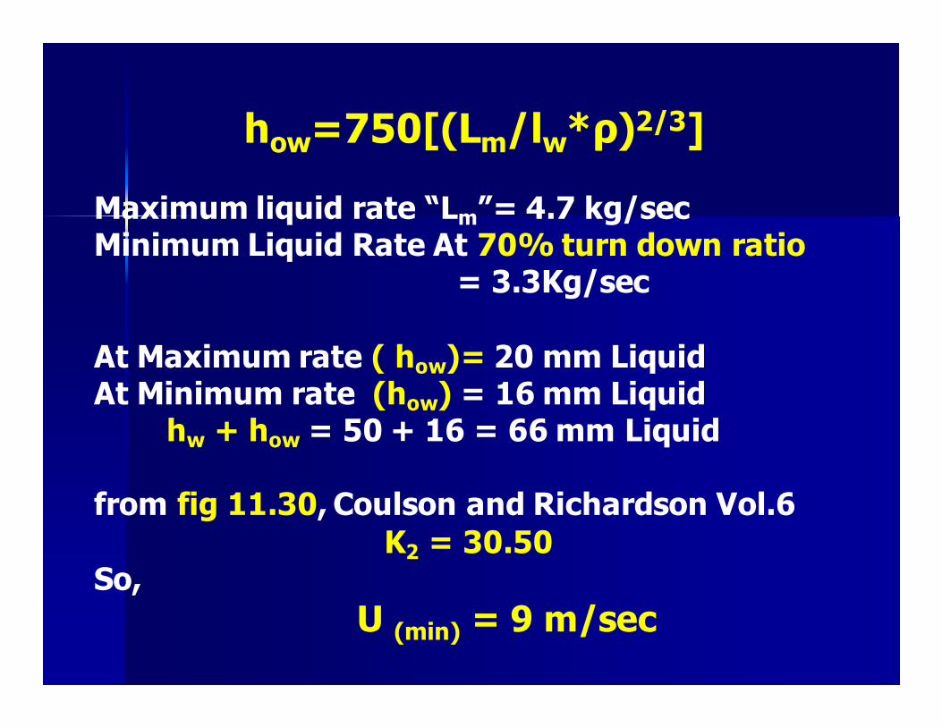
how=750[(Lm/lw*ρ)2/3] Maximum liquid rate “Lm”= 4.7 kg/sec Minimum Liquid Rate At 70% turn down ratio = 3.3Kg/sec
At Maximum rate ( how)= 20 mm Liquid At Minimum rate (how) = 16 mm Liquid hw + how = 50 + 16 = 66 mm Liquid from fig 11.30, Coulson and Richardson Vol.6
K2 = 30.50 So,
U (min) = 9 m/sec
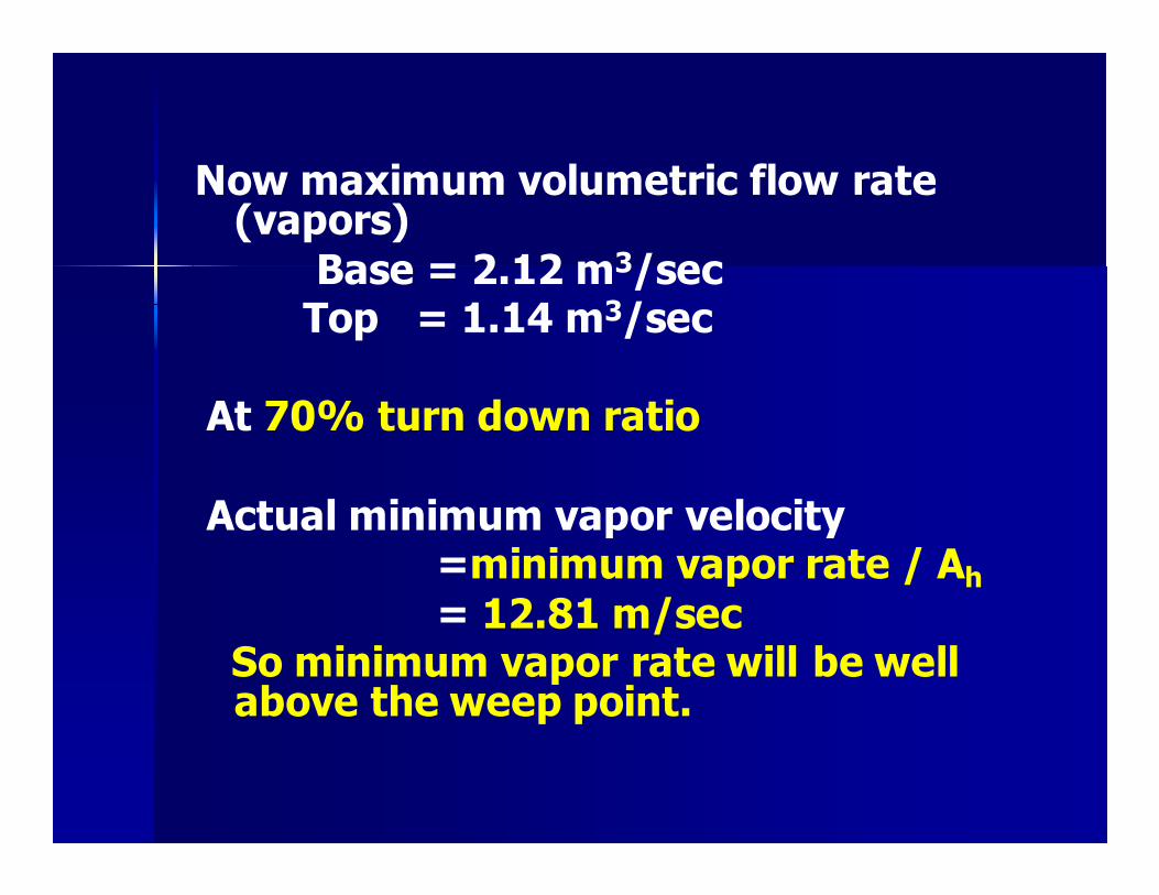
Now maximum volumetric flow rate (vapors)
Base = 2.12 m3/sec Top = 1.14 m3/sec
At 70% turn down ratio
Actual minimum vapor velocity =minimum vapor rate / Ah
= 12.81 m/sec So minimum vapor rate will be well
above the weep point.
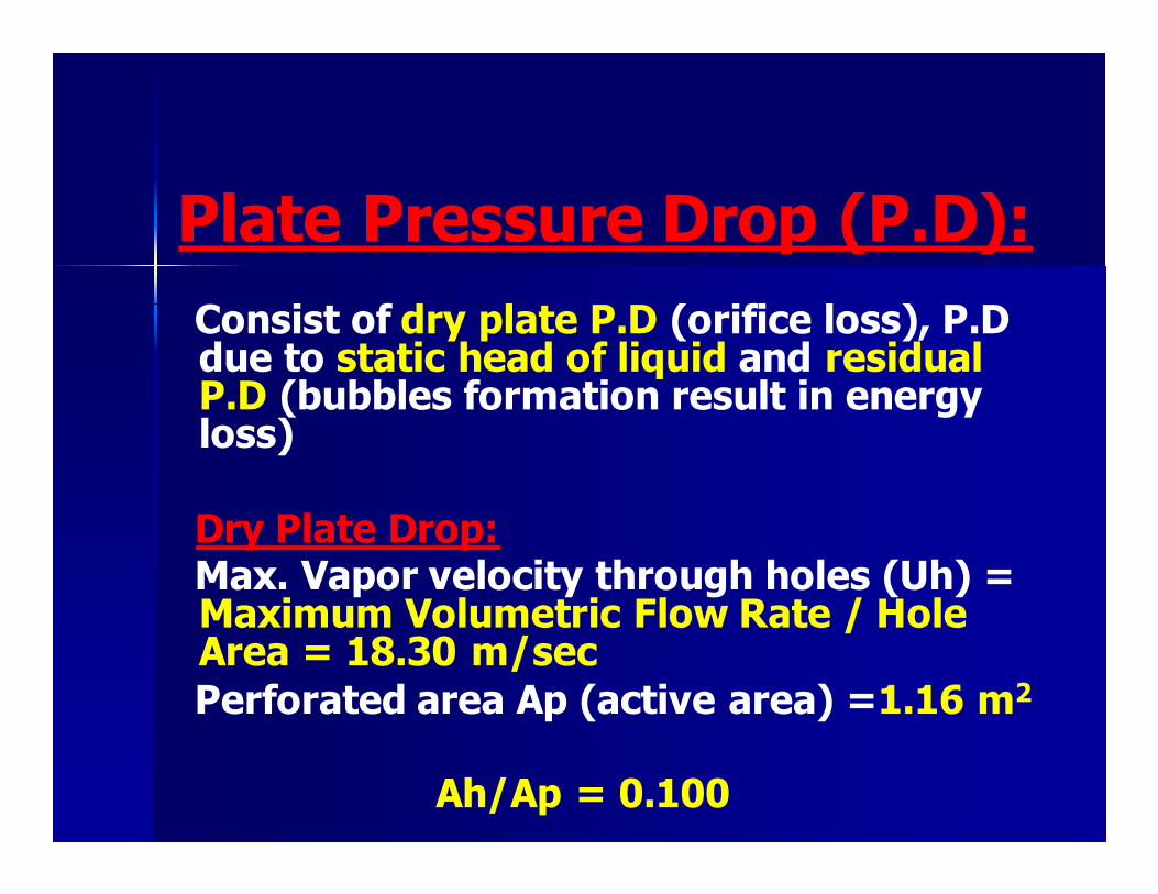
Plate Pressure Drop (P.D):
Consist of dry plate P.D (orifice loss), P.D due to static head of liquid and residual P.D (bubbles formation result in energy loss)
Dry Plate Drop: Max. Vapor velocity through holes (Uh) =
Maximum Volumetric Flow Rate / Hole Area = 18.30 m/sec
Perforated area Ap (active area) =1.16 m2
Ah/Ap = 0.100
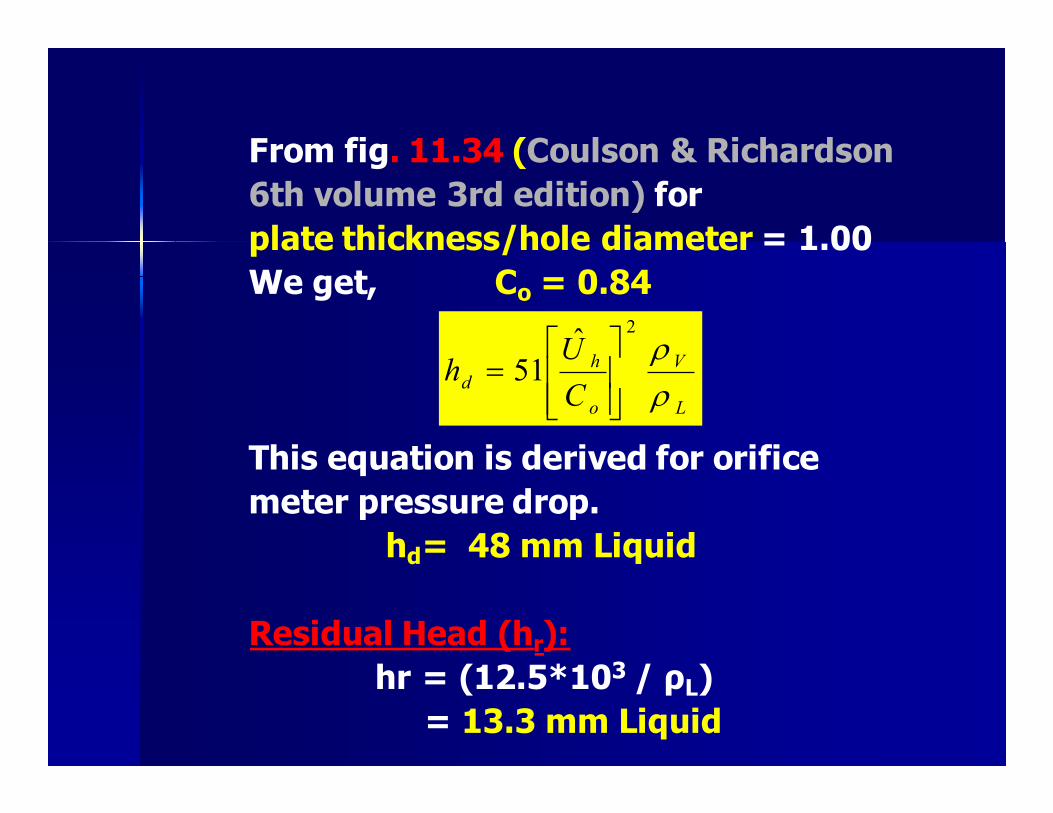
From fig. 11.34 (Coulson & Richardson
6th volume 3rd edition) for
plate thickness/hole diameter = 1.00
We get, Co = 0.84
This equation is derived for orifice
meter pressure drop.
hd= 48 mm Liquid
Residual Head (hr):
hr = (12.5*103 / ρL)
= 13.3 mm Liquid
L
V
o
h
dC
Uh
ρρ
2ˆ
51
=
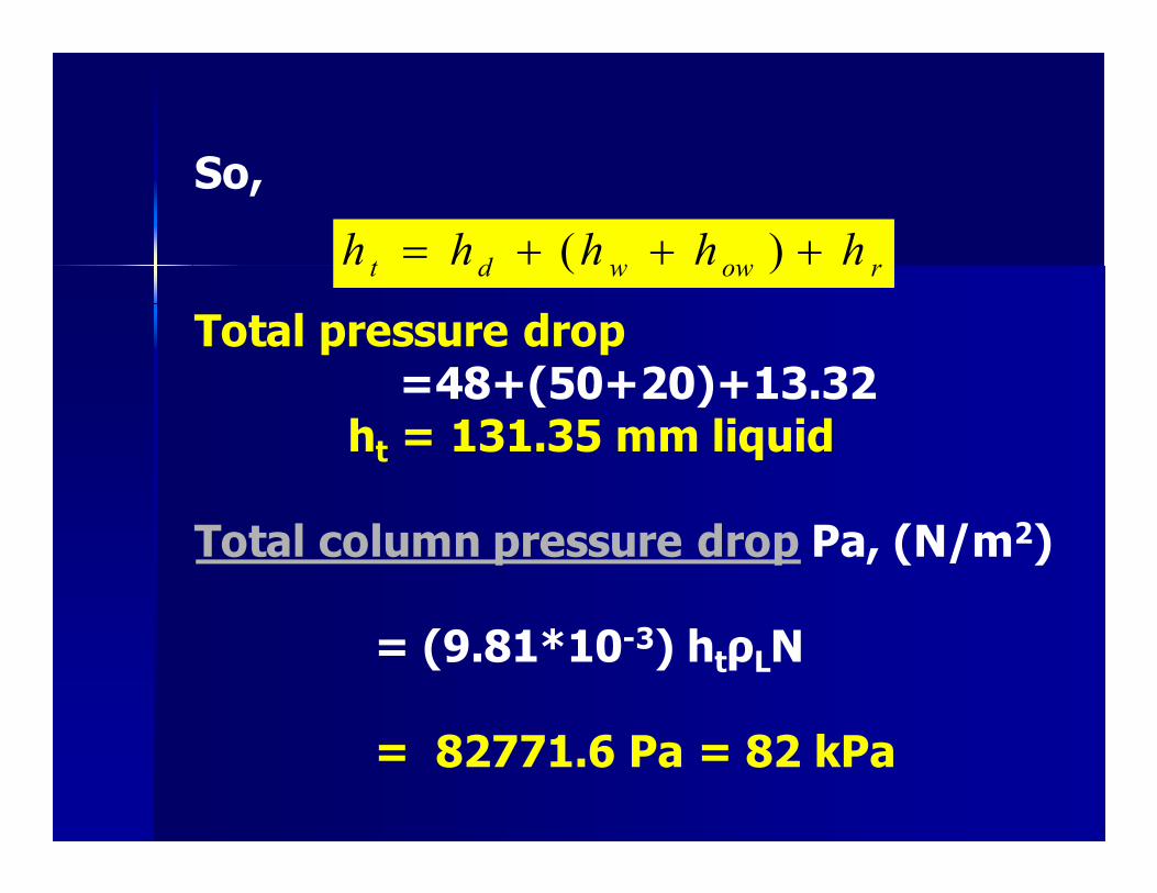
So, Total pressure drop =48+(50+20)+13.32 ht = 131.35 mm liquid Total column pressure drop Pa, (N/m2) = (9.81*10-3) htρLN = 82771.6 Pa = 82 kPa
rowwdt hhhhh +++= )(
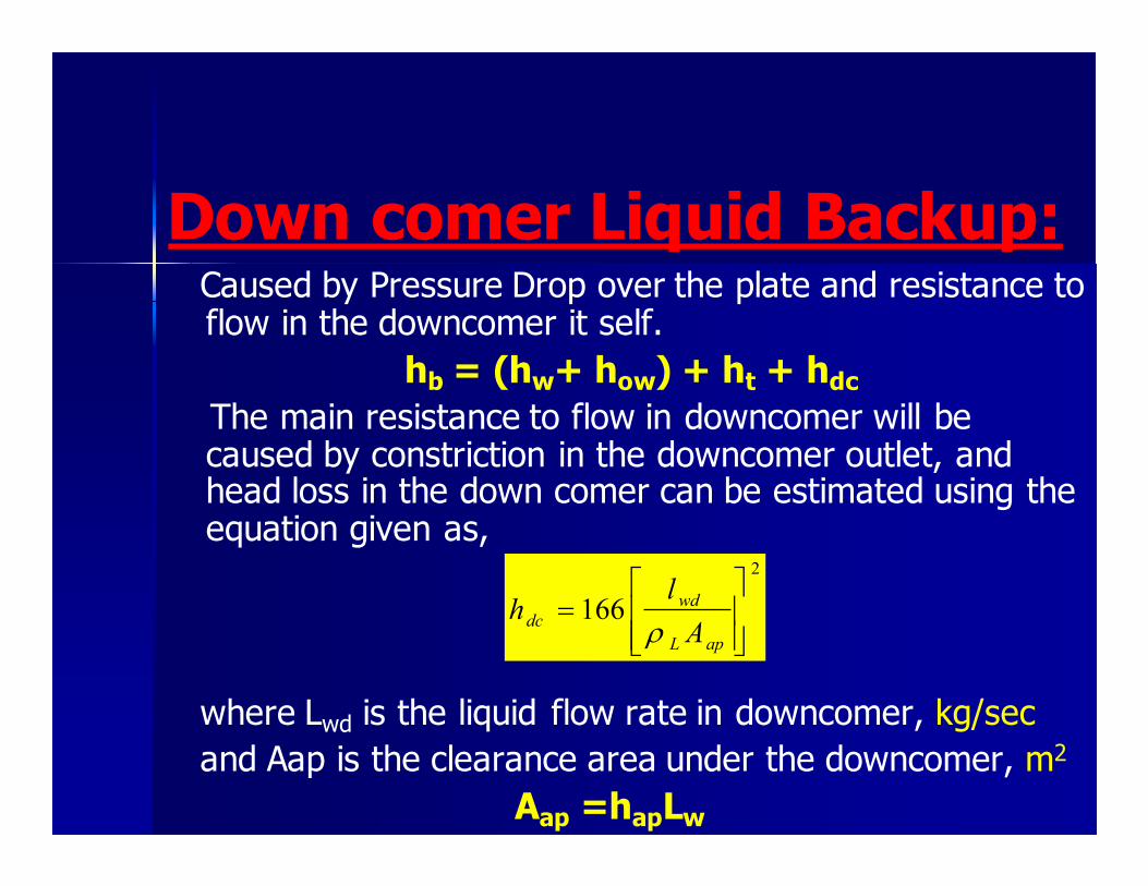
Down comer Liquid Backup: Caused by Pressure Drop over the plate and resistance to
flow in the downcomer it self.
hb = (hw+ how) + ht + hdc
The main resistance to flow in downcomer will be caused by constriction in the downcomer outlet, and head loss in the down comer can be estimated using the equation given as,
where Lwd is the liquid flow rate in downcomer, kg/sec
and Aap is the clearance area under the downcomer, m2
Aap =hapLw
2
166
=
apL
wd
dcA
lh
ρ
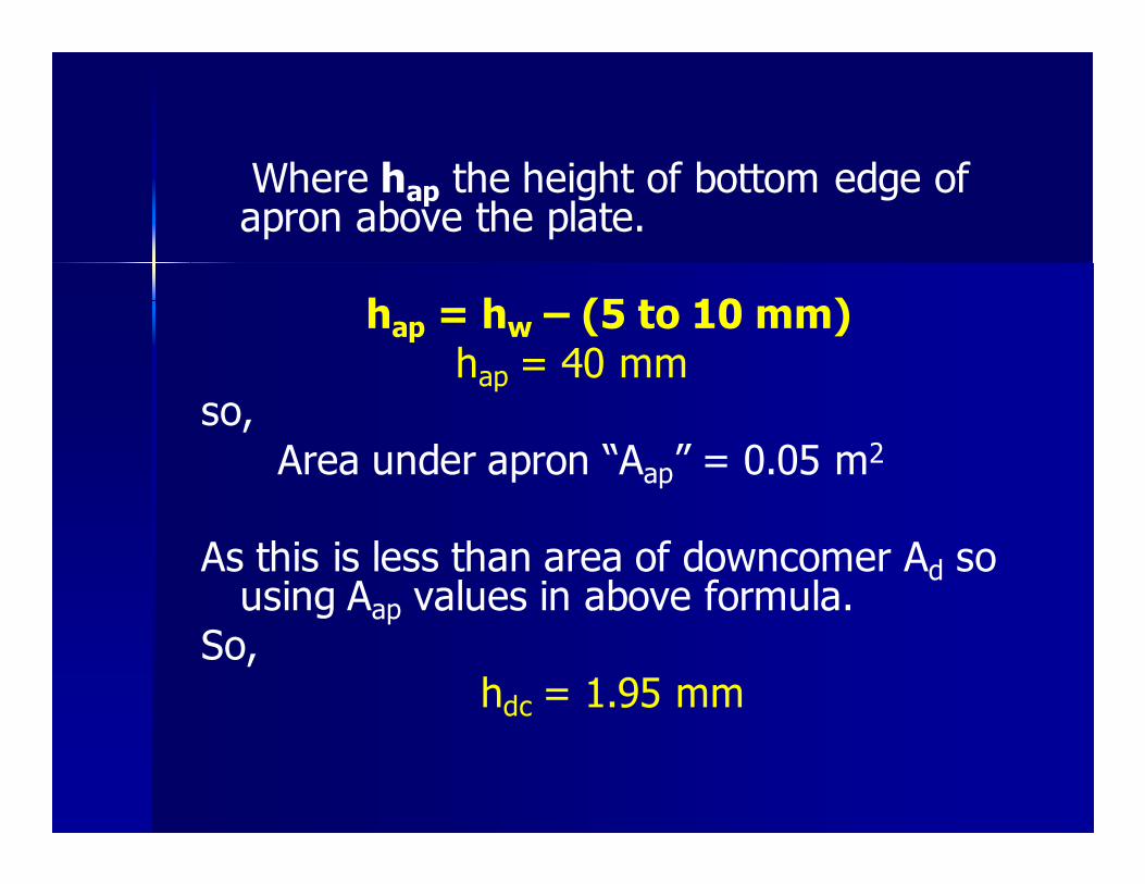
Where hap the height of bottom edge of apron above the plate.
hap = hw – (5 to 10 mm)
hap = 40 mm so,
Area under apron “Aap” = 0.05 m2
As this is less than area of downcomer Ad so
using Aap values in above formula.
So, hdc = 1.95 mm
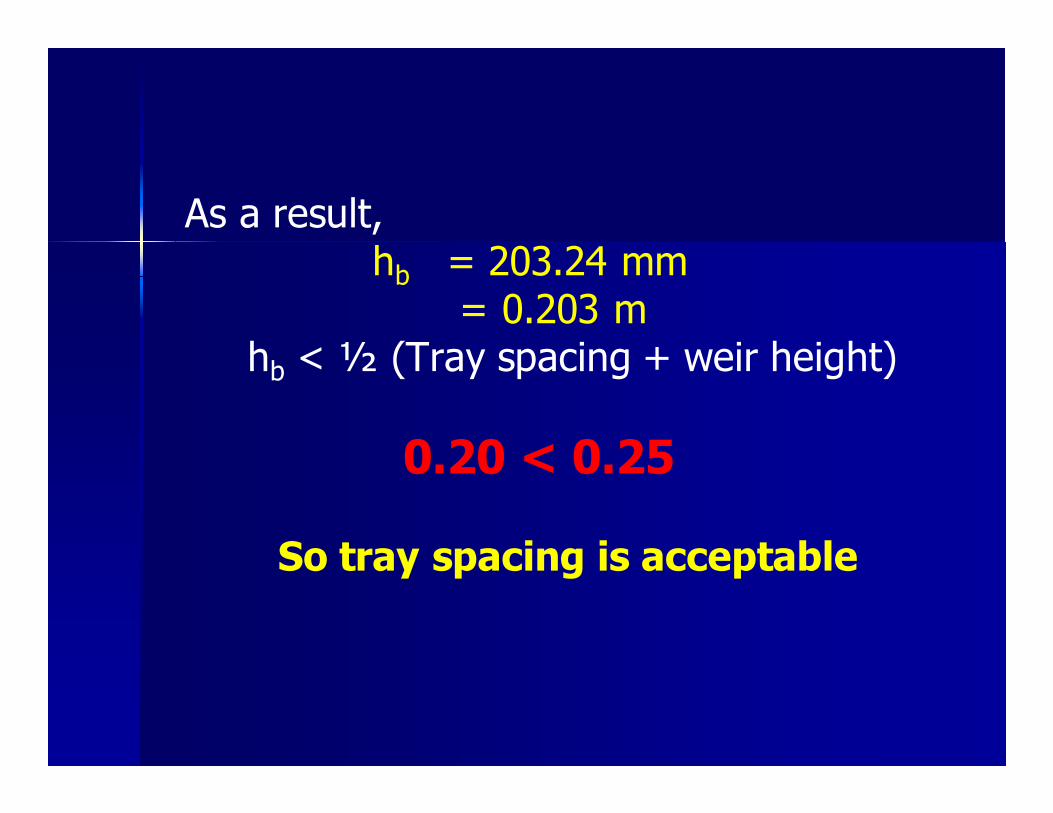
As a result, hb = 203.24 mm = 0.203 m hb < ½ (Tray spacing + weir height)
0.20 < 0.25 So tray spacing is acceptable

Check Residence Time:
Sufficient residence time should be allowed in the downcomer for the entrained vapors
to disengage from liquid stream to prevent aerated liquid being carried under the downcomer.
tr =Ad hbc ρL/L(max)
tr = 10 sec
It should be > 3 sec. so, result is satisfactory

Check Entrainment:
(un) actual velocity = (maximum volumetric flow rate at base Vm / net area An)
(un) actual velocity = 1.51 m/sec
Velocity at flooding condition Uf = 1.67 m/sec
So Percent flooding =un/ uf = 0.90 = 90%
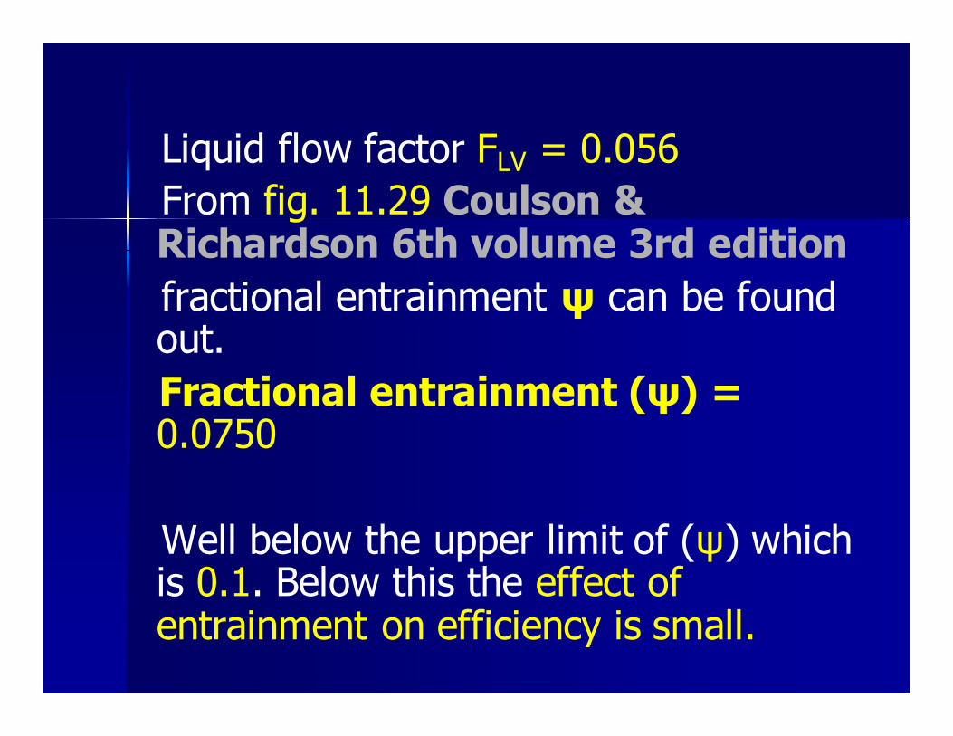
Liquid flow factor FLV = 0.056
From fig. 11.29 Coulson & Richardson 6th volume 3rd edition
fractional entrainment ψ can be found out.
Fractional entrainment (ψ) = 0.0750
Well below the upper limit of (ψ) which is 0.1. Below this the effect of entrainment on efficiency is small.
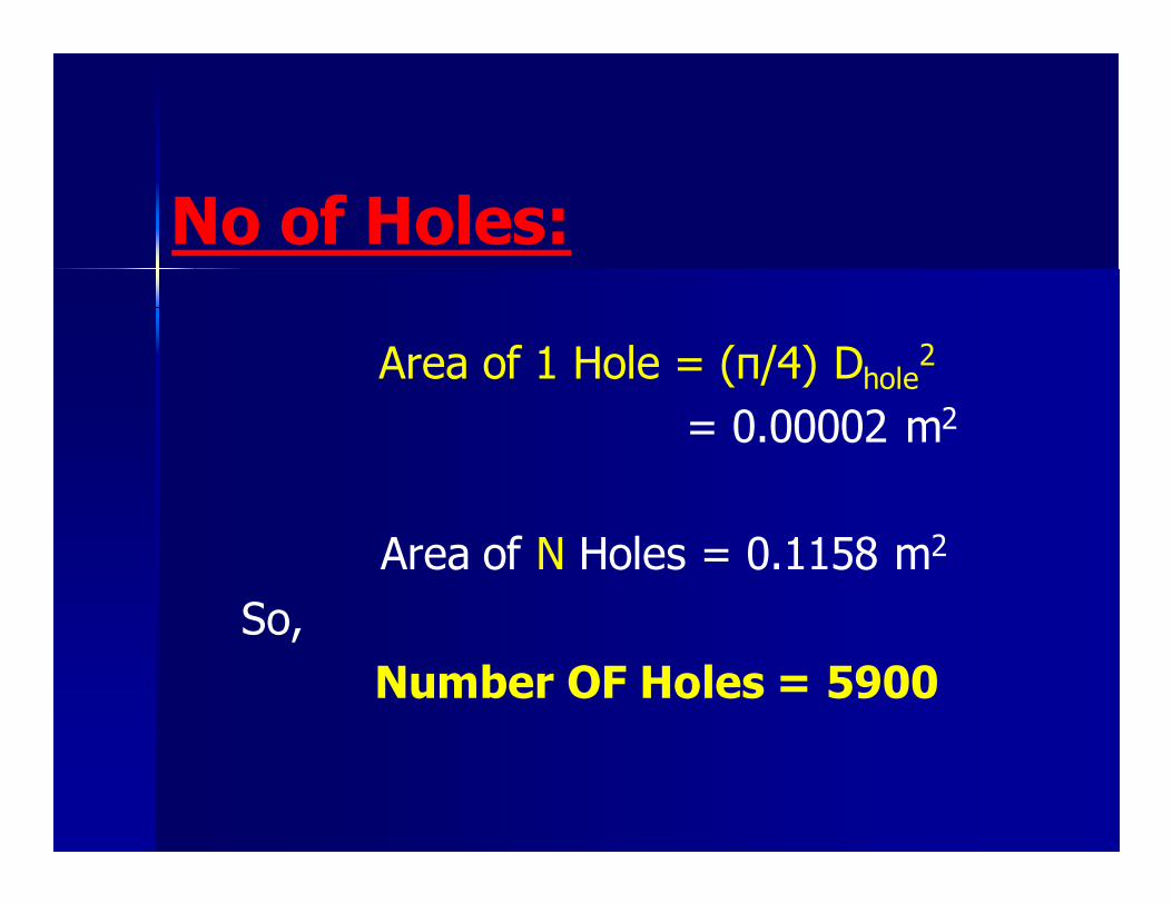
No of Holes:
Area of 1 Hole = (π/4) Dhole2
= 0.00002 m2
Area of N Holes = 0.1158 m2
So,
Number OF Holes = 5900
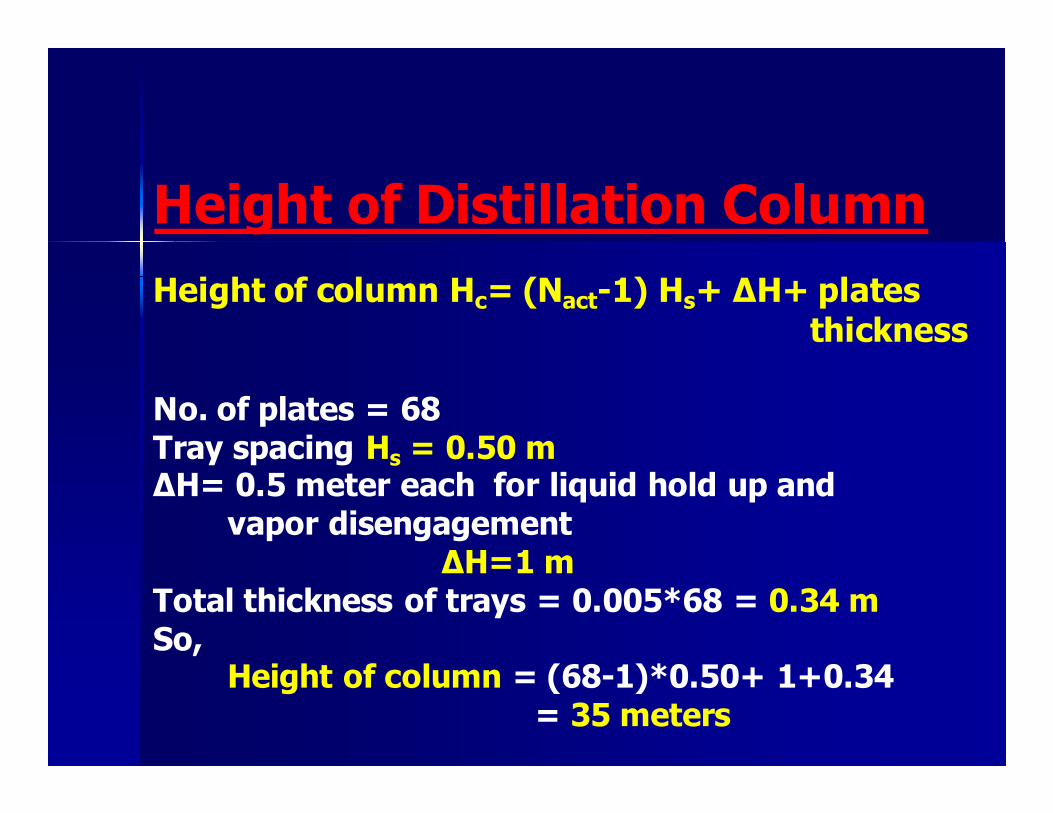
Height of Distillation Column
Height of column Hc= (Nact-1) Hs+ ∆H+ plates thickness No. of plates = 68 Tray spacing Hs = 0.50 m ∆H= 0.5 meter each for liquid hold up and vapor disengagement ∆H=1 m Total thickness of trays = 0.005*68 = 0.34 m So, Height of column = (68-1)*0.50+ 1+0.34 = 35 meters

1.45m height=35m
Hole
diameter=5mm
No. of
holes=5900
hap=40 mm
h W=50 mm
how=Weir crust Plate Specifications
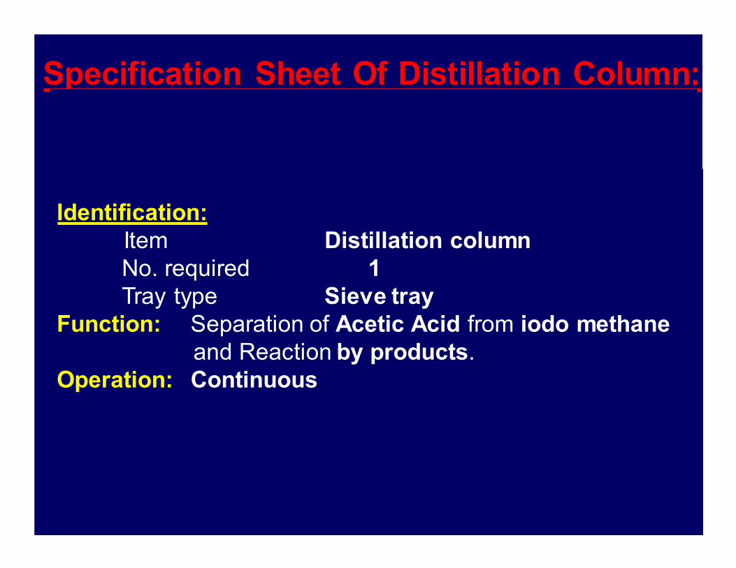
Specification Sheet Of Distillation Column:
Identification:
Item Distillation column
No. required 1
Tray type Sieve tray
Function: Separation of Acetic Acid from iodo methane
and Reaction by products.
Operation: Continuous

Feed
Top
Bottom
Amount
4755 Kg/hr
1968 Kg/hr
2786 Kg/hr
Composition
of
Acetic Acid
0.64
0.005
0.99
Temp.
119oC
71oC
118oC
Material handled:
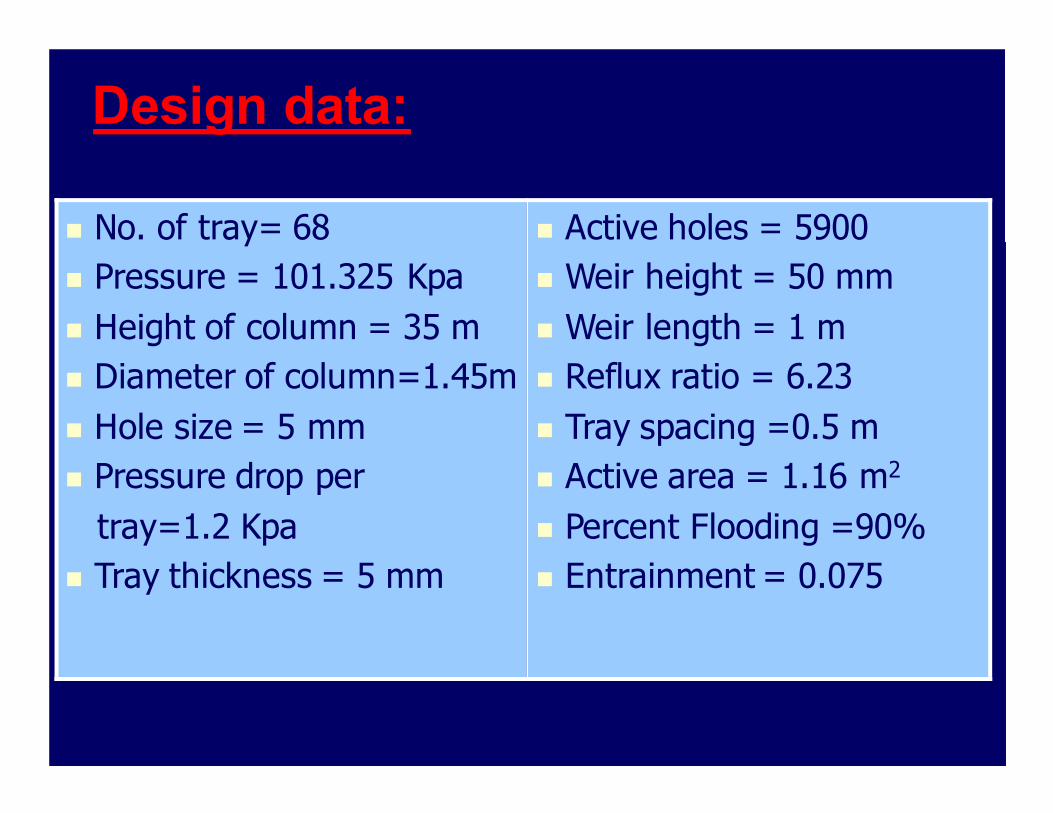
Design data:
� No. of tray= 68
� Pressure = 101.325 Kpa
� Height of column = 35 m
� Diameter of column=1.45m
� Hole size = 5 mm
� Pressure drop per
tray=1.2 Kpa
� Tray thickness = 5 mm
� Active holes = 5900
� Weir height = 50 mm
� Weir length = 1 m
� Reflux ratio = 6.23
� Tray spacing =0.5 m
� Active area = 1.16 m2
� Percent Flooding =90%
� Entrainment = 0.075

References � Coulson & Richardson 6th volume 3rd
edition
� Plant Design and Economics for Chemical Engineering
� Coulson & Richardson 2th volume 5th edition
� Perry’s Chemical engineer’s hand book

The End