distance relay
TRANSCRIPT

1
Modeling and Testing of a Digital Distance Relay Using MATLAB/SIMULINK
Li-Cheng Wu, Chih-Wen Liu,Senior Member,IEEE, Ching-Shan Chen,Member,IEEE
Department of Electrical Engineering, National Taiwan University, Taipei, Taiwan
Abstract— This paper describes modelling and testing of a digital distance relay for transmission line protection using MATLAB/SIMULINK. SIMULINK’s Power System Blockset (PSB) is used for detailed modelling of a power system network and fault simulation. MATLAB is used to implement programs of digital distance relaying algorithms and to serve as main software environment. The technique is an interactive simulation environment for relaying algorithm design and evaluation. The basic principles of a digital distance relay and some related filtering techniques are also described in this paper. A 345 kV, 100 km transmission line and a MHO type distance relay are selected as examples for fault simulation and relay testing. Some simulation results are given. Index Terms—Digital relay 、 Digital distance relay 、Electromagnetic Transient Program (EMTP)、Automatic test。
I. INTRODUCTION
For transmission lines protection, choosing a suitable relay type or relay’s setting is essential. Generally speaking, we may make the fault analysis and the test by the simulation software, and according to the actual system requirement, choose the suitable protective relay, but for reliability and security considerations, the massive simulations tests are usually undertaken. This is a quite numerous and diverse job; therefore, having a superior simulated environment is important.
The EMTP [1](Electromagnetic Transient Program) is the simulation tool that is used to simulate the electromagnetic transient phenomenon, and power system faults analysis, and it is one of the most widely used programs in the electric utility since 1970. Generally speaking, Protective relay performance has been tested with the waveform signals generated by the non real-time simulator like EMTP. This approach has the disadvantage that it’s difficult to provide real-time test for the relay algorithm dynamically. In addition, we can’t finished most test tasks at the same time with the tool.
In school and industry, simulation tools based on MATLAB/SIMULINK [2] are becoming popular for engineering applications. The MATLAB involves many high instructions and tools for some systems designing applications and developing algorithms and the SIMULINK provides excellent GUI (Graphical User Interface) interface and block module that will allow the users to rapidly and easily build and simulate system models and executive massive simulation tests at the same time. Furthermore, since the MATLAB/SIMULINK contain Power System Block Set Toolbox [3], the software turn into a powerful power systems simulation and
analysis tool [4]. This tool was modelled by using a graphically Object-Oriented environment approach integrated with the digital calculate technology that gives more flexibility to create simulation system; therefore, we can quickly develop a program of protective relay algorithms, and a model of protection relays. Because they commonly exist in the same environment that involves communication ability, it is very easy to develop a convenient graphical tool for building interactive relay test system.
The above-mentioned excellent advantages that MATLAB/SIMULINK has make MATLAB/SIMULINK a convenient and interactive tool for both numerous analysis and direct communications with relay’s test program. This paper describes how to use MATLAB/SIMULINK for automatic, interactive, and high performance testing relay system. Some examples and simulation results are also provided in the paper.
II. ALGORITHM OF DIGITAL DISTANCE RELAY
Digital distance protection is a universal short-circuit protection. It’s mode of operation is based on the measurement and evaluation of the short-circuit impedance, which is named by the algorithm of digital distance relay. This algorithm is used to input signals to DSP by discrete voltage and discrete current to judge whether faults occur or not. However, this method is just a program. MATLAB has the advantage of conducting massive calculation functions and its program can be easily developed. Therefore, it is a very suitable tool of protective relay designs and applications for protection engineers.
It can’t be denied that graphics reach out to people better than texts do. In addition, we focus not only on the correction of relay operations, but also on the dynamic characteristics of relay. Therefore, if we can use graphics to show the variance of impedances trace, then the software of interface will become more user-friendly and convenient. MATLAB includes excellent graphics capacity and multi-dimension of graphic function, and can change graphics parameters at the same time. Therefore, many graphs can be shown on the same window to make comparison with one another. This paper focuses on the model and test of digital distance relay. Therefore, the principles and relating techniques of the distance relay will be discussed first, followed by the description of the distance relay practice by MATLAB.
Distance relays are also named impedance relays. They are used to calculate line impedance by measurement of voltages and currents on one single end. For example, for MHO type distance relays, the relays compare the

2
setting impedance with the measurement impedance to determine if the fault is inside or outside the protected zone. They immediately release a trip signal when the impedance value is inside the zone 1 impedance circle of distance relay. For security protection consideration, the confirmation of a fault occurrence will not be made until successive trip signals are released in one season.
Different formulas should be adopted when calculating the fault impedance due to different fault types. Table 1 indicates calculation formula for all of the fault types [5]. Any three-phase faults can be detected from every formula in Table 1. In order to reduce calculation burden, we design a fault detector and fault type selector. The fault detector can judge which fault type it is and then calculate fault impedance by selecting a suitable formula from Table 1. If we don’t use fault type judgment first, then the distance relay of programs must be calculated by all the six formulas in table 1 at the same time, which causes much calculation burden.
Table 1 fault impedance calculation formula on difference faults Fault Type Formula AG VA/(IA+3kI0) BG VB/(IB+3kI0) CG VC/(IC+3kI0) AB or ABG (VA-VB)/ (IA-IB) BC or BCG (VB-VC)/ (IB-IC) CA or CAG (VC-VA)/ (IC-IA)
Where A、B and C indicates number of phase, G is ground fault ,V and I are phasor of voltage and current, k=(Z0-Z1)/Z1,Z0 and Z1 are line of impedance zero-sequence, positive- sequence respectively. I0 is zero-sequence current.
When the distance relays receive discrete voltage and current signal, it has to convert them to phasor. The Discrete Fourier Transform (DFT) is the most popular method to estimate fundamental phasors for digital relaying. The full-cycle DFT is described as following equation (1):
∑−
=
π−=1N
0k
Nk2jkex
N2X / (1)
Where X is complex phasor, kx is the sample discrete data of the signal, and N is the number of samples per cycle.
Equation (1) is the formula of full-cycle DFT. When a signal is sampled with 32 samples per cycle, as an example, then MATLAB DFT program can be written as follows:
N = 32; X = 0; for k = 1:N X = X + x(k)*exp(-j*2*pi/32*(k-1)); end X = X*2/N;
In addition, when a fault occurs on transmission lines,
the voltage and current signals are severely distorted. These signals may contain decaying dc components, subsystem frequency transients, high frequency oscillation quantities, and etc. The higher frequency components can
be eliminated using low pass anti-aliasing filters with appropriate cut-off frequency, but the anti-aliasing filters cannot remove decaying dc components and reject low frequency components. This makes the phasors very difficult to be quickly estimated and affects the performance of digital relaying. Therefore, we usually use the mimic filter to removed the dc-offset components [6]. The mimic filter can be developed by digital method. Here, we want to pass the fundamental frequency signal (60Hz) by the filter. Then, assuming the gain K equals 1 and the samples frequency is sf ( ss T1f /= ), finally, we obtain a formula (2)
sssss TfjKTfKf1K ωτ+ωτ−τ+ sincos)( =1 (2) Where 602 **π=ω , τ is time constant for user definition.
To solve equation (2) can get the gain K
)( 22 NM1sqrtK+
= (3)
Where
)**cos(s
ss f602ff1M π
τ−τ+= (4-1)
)**sin(s
s f602fN π
τ= (4-2)
When we use mimic filter to remove the dc-offset components, MATLAB program is described as follows:
t=2*1/60; % assumed time constant = 2
cycles 6032fs *= ; % sampling frequency
M=1+t*fs-t*fs*cos(2*pi*60/fs); N=t*fs*sin(2*pi*60/fs); K=sqrt(1/(M^2+N^2)); b=[K*(1+t*fs) -K*t*fs]; a=[1]; ia_mf=filter(b,a,ia);
As shown in the above equation, the current ia is through the mimic filter in order to remove the dc-offset components. Finally, we get a fundamental frequency wave ia_mf .
From the above discussion, we know that MATLAB can easily finish all of algorithms for protective relays. With the advantage that SIMULINK can easily simulate power system faults, the design and the test of protective relays can be achieved with ease. Its major characteristic of integrating system fault simulation and protection relay algorithms in a software system can enhance the efficiency of protection relay test.
III. POWER SYSTEM ESTABLISHMENT AND SIMULATION
In order to get exact simulation results, we must establish accurate network model. SIMULINK/Power System Blockset (PSB) is used to create power system model for simulation. With the updated versions of MATLAB/SIMULINK, the model development of power system components is onward to perfection. Due to the

3
fast development of new technologies, which improve the power transfer efficiency and the optimum utilization of system capability, power electronic equipment like TCSC、UPFC、STATCOM…and so on may be widely used in power systems In the future. Thus, the selection and the setting of protective relay should be evaluated and tested thoroughly [7]. Here, SIMULINK includes variant basic power components, which can be used alone or in combinative use to finish all kinds of power system network simulations.
It is very easy to create power system in SIMULINK environment, which allows users to build a model by simple “click and drag’’ procedures. Because all of the electrical parts of the simulation interact with the SIMLLINK’S extensive modelling library, it is not just
possible to easily draw the power system network, but also to include its interactions with every electrical component. In addition, the simulation system of block component can set relation electrical parameters from MATLAB commands.
One thing should be noted is that SIMULINK is more suitable for a small system for simulated tests. Execution speed of the simulation system will become slow when simulating system is large. Luckily, the protective relays are for protection of one article of electrical equipment, so we just focus on protected equipment. Other components can be made in equivalent value. Therefore, by reducing the complexity of the simulation system, the simulation system result will be in high performance.
Fig. 1. One-line diagram of simulation system
Fig. 2. SIMULINK/Power System Block constructs the simulation systems diagram

4
Fig. 3. Main window and parameter interface for simulation systems
This section describes the performance test and verification of transmission line protection of distance relays using MATLAB/SIMULINK. How to use SIMULINK of the PSB to build transmission lines systems model will be discussed as follows. With reference to Fig. 1 One-line diagram of simulation system, we can establish the simulation system diagram in Fig. 2. The simulation system of each end source can be replaced by the The’venin equivalent circuits. However, we can completely finish all of the test circuits with the use of the source and the model of coupling component. Each element value of the test system can be set by power flow data and short-circuit capacity data. Generally speaking, we need to get voltages and current signal data by current transformer (CT) and voltage transformer (VT) as shown in Fig.2 CTS and VTS respectively because distance relays need three-phase voltages and three-phase currents for the impedance calculation. The design of digital distance relays of algorithm is based on the component of fundamental frequency (60Hz). When power systems fault occurs, the signals may contain high frequency components. These higher frequency components must be eliminated, so we adopt analogue low pass filters of block in the simulation systems in SIMULINK. This block can be defined as filter of types (Low pass, Band pass, and High pass), order, and cut-off frequency etc. by user. These are excellent characteristics. In addition, SIMULINK provides some options like real-time display, storing data in WORKSPACE and hard disk after the signals data is released by filter. As shown in Fig.2, we capture signals and store them in WORKSPACE from the simulation systems, which is provided for using input of distance relay algorithm. About transmission lines model, SIMULINK provides Pi and distribution model, which can sets parameters as numbers of phase, frequency, resistance,
inductance, capacitor, and line length etc. This paper uses distribution model for transmission line model of the power systems simulation. In Fig. 2, the block for fault type selection and fault resistances setting are located below two distribution model blocks.
Here, we have finished the power system simulation model as shown in Fig.2, but the graphic shown in window is a bit messy. Thus the SUBSYSTEM block is used by covering all of blocks to produce a single block, as shown in Fig. 3. Fault simulation block. If we double click the block, the interactive interface window on right side of Fig. 3. will be shown again, in which the interface window can renew some parameters for next time simulation when the simulation is finished. In addition, we can simulate many cases at the same time. As discussed above, the protective relay simulation system has become a system of easy use and with efficiency.
Fig. 4. Protective relay test systems based on MATLAB/SIMULINK
Here, when we compare MATLAB/SIMULINK with EMTP/ATP, we will see which one is better for the protective relay simulation systems. The following items summarize their most important differences in protection systems simulation: 1. The EMTP/ ATP is specific software to simulate
power system transient problem, whereas the MATLAB/SIMULINK can be used to simulate power system faults and protective relay algorithm at the same time.
2. ATP/EMTP is designed to simulate the physical processes of transmission lines and transformers quickly and in a convenient way but

5
MATLAB/SIMULINK offers more possibilities in power electronics, signal processing and control.
3. Users can easily create new relay model with MATLAB/SIMULINK, whereas EMTP/ ATP doesn’t have such capacity.
4. MATLAB/SIMULINK encompasses better graphic function tools than EMTP/ATP of PCPLOT, PLOTXY and so on.
Therefore, this paper selects MATLAB/SIMULINK for interactive automatic relay test systems.
IV. INTERACTIVE RELAY TEST SYSTEMS
Based on the discussion made in the previous two sections, we can establish interactive relay test systems based on MATLAB/SIMULINK as shown in Fig. 4. We can use MATLAB to write main program for protective relay test. The main program can not only start fault simulation systems with SIMULINK but also give commands and parameters to renew simulation systems at the same time. As indicated in Fig. 3, we can change parameters of simulation systems including fault locations, fault resistances, fault time, and fault types etc., and then the main program will execute setting and change value. Finally the main program controls SIMULINK execution dynamic of simulation as shown on Fig. 2. After the simulation is finished, the simulation result data will be stored in WORKSPACE or hard disk, and its waveform can be shown directly on screen through user’s command. So far we have finished fault simulation task, and then got related input data for protective relay algorithm. As far as the distance relays in this paper are concerned, we need to get three-phase voltages and three-phase currents from S terminal (Fig. 1.).
In the next step, input the simulation result data to protective relay algorithm by MATLAB to distinguish whether the circuit breaker (C.B.) action occurs or not from plan logic. When the fault impedance is calculated and it is satisfied in the protection zone 1, the protective relay operation then releases trip signal to C.B. without additional delay. Here, MATLAB can easily show impedance trace on screen for user’s verification, and store the test records. So far we have only finished one fault case for verification relay action. After this test is finished, the main program can automatically change parameters again to execute simulations, tests, and records continually. With the inclusion of the loop function and the modification of system parameters, the main program can finish hundreds and thousands of case tests at the same time to meet the purpose of having automatic tests for protective relays. The reason why this function is so powerful is that we integrate MATLAB/SIMULINK into one single environment and make use of its easy communication function.
In addition to the above-mentioned advantage of automatic protective relay tests, MATLAB can empower us to modify and adjust the problems that the initial relay design may have. With the powerful graphic function by MATLAB we can use the program to obtain easily output signal values and waveforms for relay algorithms verification. If the relay algorithm is bad, then modify it
immediately. It is very convenient for designing protective relay as well as for checking whether the setting of the interactive relay test environment is appropriate.
V. EXAMPLE
Now that the theory and the structure of the interactive relay test system are prescribed, the following begins with an example of a power transmission line of fault simulation to test relay operation. Fig. 1 depicts the 345 kV, 60 Hz simulated system one-line diagram. Fig. 2 is the simulated system model by SIMULINK. The other related parameters of the simulated system are shown in Table 2. Zone 1 is setting 80% of the total line length. This example uses MHO type to explain the relay operation performance. The mimic filters with time constant 2 cycles, the phase difference between ES and ER is 15 degrees, and the sampling frequency is 1920 Hz. The transmission line length is 100 km. The phasor is estimated by full-cycle DFT.
Table 2 The parameters of the simulation transmission system
Voltage Rating: 345 kV
System frequency: 60 Hz
Equivalent Voltage Per Unit:
.)u.p(151ES°∠= , .)u.p(01ER
°∠=
Equivalent Source Impedance:
)(72.5238.0Z 1S Ω+= , )(10738.2Z 0S Ω+=
)(19.6238.0Z 1R Ω+= , )(12.5833.0Z 0R Ω+=
Length of Transmission Line: 100 km
Line Constant:
)(275.0R0 Ω= , )mH(725.3L0 = , )nF(6.711C0 =
)(0275.0R1 Ω= , )mH(345.1L1 = , )nF(9.483C1 =
Filter:
2 Order of Butterworth Low Pass Filter, High Cut-Off
Frequency 360(Hz)
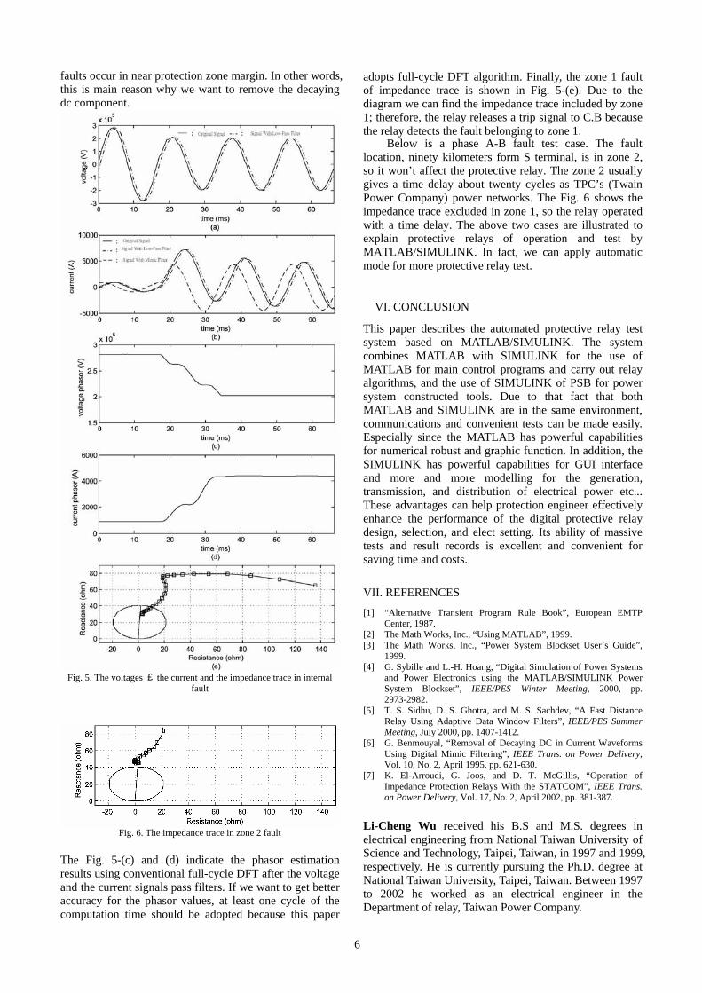
First, In order to prove digital distance relay of performance, an internal fault is applied to the power system with the phase A to ground fault, the fault resistance is 1 ohm, the fault angle is zero degree (refer to S terminal of phase A voltages waveform), and the fault is located sixty kilometers form S terminal. Therefore, the fault currents will include dc-offset components.
Fig. 5 shows the phase A current waveform, the phase A voltage waveform, and the impedance trace for the single phase to ground fault. Judging from Fig. 5-(a) and (b), filters can be eliminated high frequency components form the fault waveform, but result in signals time delay. Therefore, the cutoff high frequency can’t be set too low, otherwise, the relay operation time can be affected. As shown in Fig. 5 the mimic filter can effectively remove the decaying dc component. If the filter is no use in the relay algorithm, then the current phasor results in unstable phenomenon and the impedance trace will be oscillated. The relay may malfunction when some
6
faults occur in near protection zone margin. In other words, this is main reason why we want to remove the decaying dc component.
Fig. 5. The voltages 、the current and the impedance trace in internal
fault
Fig. 6. The impedance trace in zone 2 fault
The Fig. 5-(c) and (d) indicate the phasor estimation results using conventional full-cycle DFT after the voltage and the current signals pass filters. If we want to get better accuracy for the phasor values, at least one cycle of the computation time should be adopted because this paper
adopts full-cycle DFT algorithm. Finally, the zone 1 fault of impedance trace is shown in Fig. 5-(e). Due to the diagram we can find the impedance trace included by zone 1; therefore, the relay releases a trip signal to C.B because the relay detects the fault belonging to zone 1.
Below is a phase A-B fault test case. The fault location, ninety kilometers form S terminal, is in zone 2, so it won’t affect the protective relay. The zone 2 usually gives a time delay about twenty cycles as TPC’s (Twain Power Company) power networks. The Fig. 6 shows the impedance trace excluded in zone 1, so the relay operated with a time delay. The above two cases are illustrated to explain protective relays of operation and test by MATLAB/SIMULINK. In fact, we can apply automatic mode for more protective relay test.
VI. CONCLUSION
This paper describes the automated protective relay test system based on MATLAB/SIMULINK. The system combines MATLAB with SIMULINK for the use of MATLAB for main control programs and carry out relay algorithms, and the use of SIMULINK of PSB for power system constructed tools. Due to that fact that both MATLAB and SIMULINK are in the same environment, communications and convenient tests can be made easily. Especially since the MATLAB has powerful capabilities for numerical robust and graphic function. In addition, the SIMULINK has powerful capabilities for GUI interface and more and more modelling for the generation, transmission, and distribution of electrical power etc... These advantages can help protection engineer effectively enhance the performance of the digital protective relay design, selection, and elect setting. Its ability of massive tests and result records is excellent and convenient for saving time and costs.
VII. REFERENCES
[1] “Alternative Transient Program Rule Book”, European EMTP Center, 1987.
[2] The Math Works, Inc., “Using MATLAB”, 1999. [3] The Math Works, Inc., “Power System Blockset User’s Guide”,
1999. [4] G. Sybille and L.-H. Hoang, “Digital Simulation of Power Systems
and Power Electronics using the MATLAB/SIMULINK Power System Blockset”, IEEE/PES Winter Meeting, 2000, pp. 2973-2982.
[5] T. S. Sidhu, D. S. Ghotra, and M. S. Sachdev, “A Fast Distance Relay Using Adaptive Data Window Filters”, IEEE/PES Summer Meeting, July 2000, pp. 1407-1412.
[6] G. Benmouyal, “Removal of Decaying DC in Current Waveforms Using Digital Mimic Filtering”, IEEE Trans. on Power Delivery, Vol. 10, No. 2, April 1995, pp. 621-630.
[7] K. El-Arroudi, G. Joos, and D. T. McGillis, “Operation of Impedance Protection Relays With the STATCOM”, IEEE Trans. on Power Delivery, Vol. 17, No. 2, April 2002, pp. 381-387.
Li-Cheng Wu received his B.S and M.S. degrees in electrical engineering from National Taiwan University of Science and Technology, Taipei, Taiwan, in 1997 and 1999, respectively. He is currently pursuing the Ph.D. degree at National Taiwan University, Taipei, Taiwan. Between 1997 to 2002 he worked as an electrical engineer in the Department of relay, Taiwan Power Company.

7
His main research interests are power electronics, high voltage test and power system protection. Chih-Wen Liu (S’93-M’96-SM’02) was born in Taiwan, in 1964. He received the B.S. degree in electrical engineering from National Taiwan University (NTU), Taipei, Taiwan, and the M.S. and Ph.D. degrees in electrical engineering from Cornell University, Ithaca, NY, in 1987, 1992, and 1994, respectively. Since 1994, he has been with NTU, where he is a Professor of electrical engineering. His main research interests include application of computer technology to power system monitoring, protection, and control. His other research interests include motor control and power electronics. Ching-Shan Chen was born in Taichung, Taiwan, in 1976. He received the B.S. degree in electrical engineering from National Taiwan University of Science and Technology, Taipei, Taiwan, and the M.S. and Ph.D. degrees in electrical engineering from National Taiwan University, Taipei, Taiwan, in 1998, 2000, and 2003, respectively. At present, he works at Industrial Technology Research Institute and his research interests include distributed generation systems and computer relaying.