distance based user localization and tracking with ... ultrasonic radar system detects human motion...
TRANSCRIPT
Distance Based User Localization and Trackingwith Mechanical Ultrasonic Beamforming
Shangyue Zhu, Hanqing Guo, Junhong Xu, Shaoen WuDepartment of Computer Science
Ball State University
Abstract—Many IoT smart systems such as smart homesrequire intelligent solutions to localize and track a user in a livingspace. Traditional solutions are either too simple in capability toreveal dynamic details or invasive in privacy leaking. This workdesigns and develops a novel noninvasive distance based userlocalization and tracking solution, DiLT, for smart systems. DiLTcollects data by using commodity off-the-shelf ultrasonic sensorsfor minimal invasion on privacy, while adopting signal processingtechniques to reveal detail dynamics embedded in the sensed data.DiLT consists of a mechanical ultrasonic beam-forming design foromni-space sensing, a contrastive divergence learning to localizea user and a binary back-off algorithm to track the motion of theuser. It has been extensively evaluated in a research laboratoryroom and it demonstrates high effectiveness and accuracy inperformance in the real environment.
I. INTRODUCTION
In the era of Internet of Things today, many sensors andmodels have been developed for use in the medical industry,to provide a comfortable and convenient living space. With theadvance in computing, ambient intelligence and the miniatur-ization of technology, many smart systems have been proposed[1]. In smart systems, one critical capability required is toidentify and track the location of occupants in living space, andrecognize their daily life activities (DLA). Most smart systemsperform the user localization and tracking in two ways: one isto provide a smart environment, for example, utilizing imageprocessing based on video sensors, and the other is to havedevices installed on users, for example, equipping wearablesensors [2], because these devices can provide rich data witha highly accurate information to identify the locations. Thedownside of using video sensors for a smart environmentis that the collected data likely contains vast amounts ofpotentially privacy information, which has been a concern tomany users for long [3]. Wearable sensors on user bodies areoften taken off the body or forgotten somewhere, and thusare always unreliable to collect data. Thus, it is of ultimateinterest to design a passive and non-invasive IoT system tofor an active smart environments without concerns on userprivacy.
In this paper, we propose a novel IoT solution, Distancebased Localization and Tracking (DiLT), that collects data byusing commodity off-the-shelf ultrasonic sensor for minimalinvasion to localize and track a user in an environment. DiLTuses distance as special “signal” and adopts high-degree signalprocessing techniques to reveal detail dynamics embeddedin the sensed data. This work has the following contribu-
tions. First, to address the challenge of noise in ultrasonicmeasurement, we design a robust mechanical beamformingultrasonic system that expands the ultrasonic sensing range andcapability of conventional ultrasonic sensors. The mechanicalbeamforming ultrasonic system can collect direction-awaredata and suppress noise in data measurement. Second, thiswork designs a data processing algorithm to remove excep-tional and noisy data from the collected data, and transformthe multiple sampled data sets into a single data set. Third, wedesign a contrastive divergence learning algorithm to localizea user based on the sensed distance data with high accuracy.Forth, this paper proposes a Binary Backoff (BNB) algorithmto track down the change of user location.
The rest of this paper is organized as follows. In Section II,we present a brief overview of the fundamental principleof ultrasonic sensor and the related work. Section III nextdiscusses the detail system design of DiLT, including thephysical design, data processing, localization and trackingalgorithms. In Section IV, extensive evaluation results havebeen presented. Section V concludes this work.
II. RELATED WORK
Before the proposed DiLT is discussed, in this section, webriefly review related literacy related to our work, particularlyon ultrasonic sensing, beamforming and nontraditional local-ization.
A. Ultrasonic Sensing
The fundamental principle of ultrasonic is similar to radarsensing on radio waves. The ultrasonic wave has a frequencyhigher than the frequency of the sound wave by more than 20kHz. Ultrasonic sensors consist of an ultrasonic transmitter anda receiver. In working, the ultrasonic signal is emitted fromthe ultrasonic transmitter. When the signal hits an object, thesignal is reflected and received by the ultrasonic receiver [4].The signal is then delivered to a micro-controller for furtherprocessing to calculate the distance to the object.
1) Ultrasonic Locaization: Previous efforts have been at-tempted to use ultrasonic for localization. Two of such effortsmost related to our work are the solutions proposed by Nishidaet al [1], [3]. In the first work [3], they have multiple ultrasonictransmitters and receivers installed in a celling. This ultrasonicradar system detects human motion at a relatively high verticalposition to recognize the location of residents at a home. Theyadditionally use the reflected sound pressure to visualize the

position of human in detection area. In their other work [1]extending their first work, Nishida et al proposes a three-dimensional ultrasonic localization and tagging system. Theyuse multiple ultrasonic receivers embedded in both wall andceiling to calculate a three-distance measurement from a tri-lateration detection area. Moreover, Angelis et al [5] alsoinvestigate three-dimensional positioning based on ultrasonicsensors. They vary the sampling frequency by selecting differ-ent transmitters and receivers to track an object dynamically.Meanwhile, they also explore the miniaturization of the ul-trasonic transmitters and developed a systematic method fordefining and tagging activities with high accuracy. In addition,ultrasonic sensing has been also used in smart systems otherthan localization [6]–[13].
Many researchers have explored localization based on ultra-sonic context-aware computing. In [14], the authors investigateindoor localization with RF systems and ultrasonic. The indoorpositioning system is accessed by multiple ultrasonic emitters.The location is estimated with different ultrasonic signalreflections through marked location points. The authors of[15] develop a portable device to synchronize correspondingultrasonic location code in a period. The device is configuredto receive the timing synchronized information and to transmita location code based on the received timing synchronization.Google ATAP team has designed an mm-wave radar systemSoli [16] based on 60 GHz signals to capture subtle motionsin gestures. Soli receives reflected signal and use signalprocessing techniques to extract features and employs machinelearning to recognize different gestures with classificationalgorithms.
2) Beamforming: Beamforming has been widely used asa flexible signal processing technique usually in sensor arraysfor directional wireless communications [17]. Medical systemshave used beamforming in ultrasound imaging. For instance,a system has been proposed to use the synthetic aperturesequential beamforming (SASB) technique for clinical patientscanning [18]. This system can extract the cancer features fromlimited image information based on SASB with high qualityimage.
III. SYSTEM DESIGN
The core idea of DiLT consists of: (1) collecting staticenvironment background data, (2) gathering instantaneousscenery data, and (3) analyzing the differentiation between thescenery and the background data sets to locate and track anoccupant. This section presents the various research challengesthat DiLT has to address, the methodologies that DiLT employsand its system components.
A. Physical Design
The capability of ultrasonic sensors is so constrained thatthey can only detect the distance of an object directly in thefront. As a result, an ultrasonic sensor can only work on avery limited angle or space. The first research challenge isto design an ultrasonic system to cover the entire space of aroom. We design a mechanical ultrasonic beamforming system
by using an off-the-shelf commodity ultrasonic sensor, twoservomotors and an Arduino UNO board, as shown in Figure1. The Arduino UNO is used to both collect the data from theultrasonic sensor and control the servomotors that rotates theultrasonic sensor to scan (beamforming) to all the angles inorder to cover the whole space.
Fig. 1: System Architecture of DiLT
In particular, the ultrasonic used in our system is an HC-SR04 ultrasonic sensor that can detect a distance of 5 to 400cm (or 2 to 156 in)1. The servomotors are Micro servo thathave an active range of 0 to 180 degree. The result systemconcept diagram is plotted in Figure 2. This particular designallows each measurement to be collected as a pair of semicirclecoordinates (motorangle, distance), which is data format tobe processed.
!"
!#
!$
!%
!&
Beamforming
Ultrasonic Sensor
Servo
Computer
Wall
Door
Chair
Table
Ultrasonic Sensor
!"
!%
!$!#
!&
!'
!(Valid Points
Out of range
Range of Ultrasonic
Sensor:
5 cm - 400 cm
(a) Ultrasonic scan with Mechanical Beamforming (b) Noise in Environment Data
Fig. 2: Ultrasonic Beamforming Concept
B. Data Collection and Formatting
The data collection includes gathering both static environ-ment background data and dynamic scenery data. Becauseof the coarse resolution and accuracy of an off-the-shelfultrasonic sensor, one data collection cycle occurs in the wayof several repeated scans so that data analysis can be employedto remove exceptional data. In particular, the motors repeat therotation from 0◦ to 180◦ and then back to 0◦ for several loops
1Although the sensor specification indicates the range 2 - 400 cm, our actualvalidation shows the reliable range is 5 - 400 cm
during one data collection task. As a result, each data entry ispresented by a pair of metrics (motorangle, distance).
The data collected in one task cycle of several repeatedrotation loops is formatted as a distance matrix X ∈ Ry×n,where y refers to the number of scanned spots (or angles) in asingle rotation loop, and n refers the number of scan rotationloops in a task cycle. xi,j is therefore the distance measuredfor the ith angel in the jth rotation loop. In another word, acolumn of the matrix represents the measured distances of ally angels in a certain rotation loop.
X =
x00 x01 · · · x0n−1
x10 x11 · · · x1n−1
......
......
xy0 xy1 · · · xyn−1
(1)
C. Data Processing
After the raw sensor data are obtained, a serial of dataprocessing has to be performed before they can be mined forobservations.
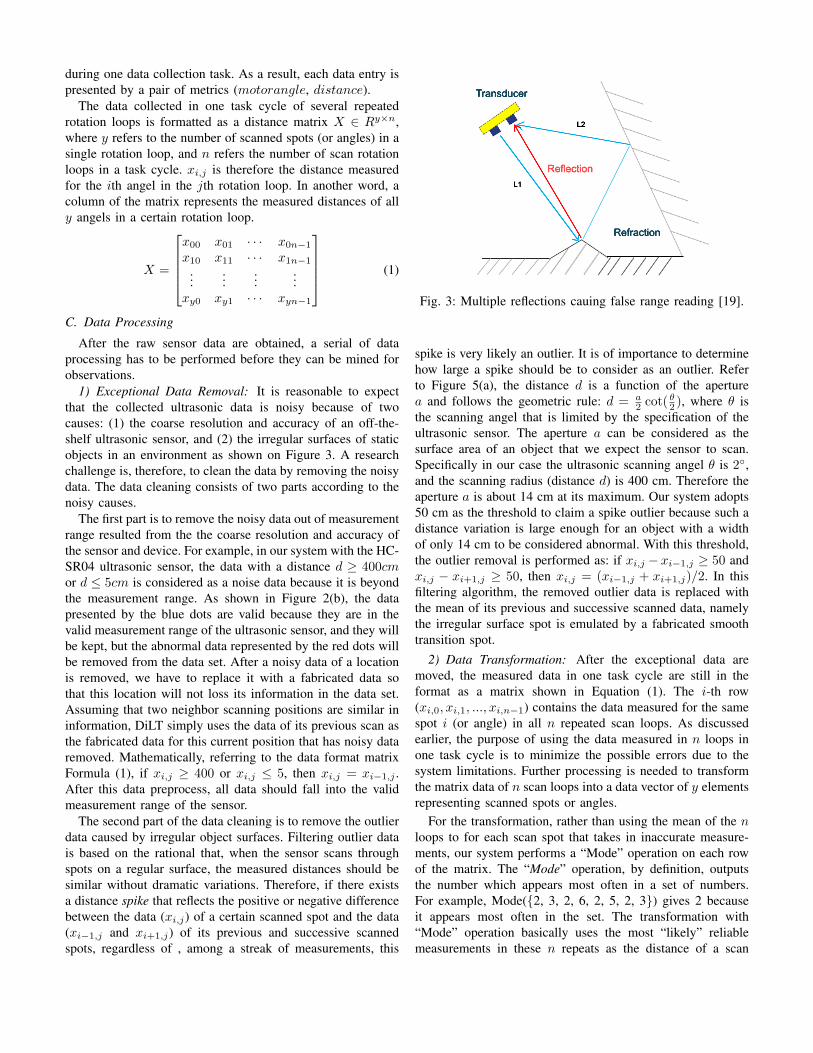
1) Exceptional Data Removal: It is reasonable to expectthat the collected ultrasonic data is noisy because of twocauses: (1) the coarse resolution and accuracy of an off-the-shelf ultrasonic sensor, and (2) the irregular surfaces of staticobjects in an environment as shown on Figure 3. A researchchallenge is, therefore, to clean the data by removing the noisydata. The data cleaning consists of two parts according to thenoisy causes.
The first part is to remove the noisy data out of measurementrange resulted from the the coarse resolution and accuracy ofthe sensor and device. For example, in our system with the HC-SR04 ultrasonic sensor, the data with a distance d ≥ 400cmor d ≤ 5cm is considered as a noise data because it is beyondthe measurement range. As shown in Figure 2(b), the datapresented by the blue dots are valid because they are in thevalid measurement range of the ultrasonic sensor, and they willbe kept, but the abnormal data represented by the red dots willbe removed from the data set. After a noisy data of a locationis removed, we have to replace it with a fabricated data sothat this location will not loss its information in the data set.Assuming that two neighbor scanning positions are similar ininformation, DiLT simply uses the data of its previous scan asthe fabricated data for this current position that has noisy dataremoved. Mathematically, referring to the data format matrixFormula (1), if xi,j ≥ 400 or xi,j ≤ 5, then xi,j = xi−1,j .After this data preprocess, all data should fall into the validmeasurement range of the sensor.
The second part of the data cleaning is to remove the outlierdata caused by irregular object surfaces. Filtering outlier datais based on the rational that, when the sensor scans throughspots on a regular surface, the measured distances should besimilar without dramatic variations. Therefore, if there existsa distance spike that reflects the positive or negative differencebetween the data (xi,j) of a certain scanned spot and the data(xi−1,j and xi+1,j) of its previous and successive scannedspots, regardless of , among a streak of measurements, this
Fig. 3: Multiple reflections cauing false range reading [19].
spike is very likely an outlier. It is of importance to determinehow large a spike should be to consider as an outlier. Referto Figure 5(a), the distance d is a function of the aperturea and follows the geometric rule: d = a
2 cot(θ2 ), where θ is
the scanning angel that is limited by the specification of theultrasonic sensor. The aperture a can be considered as thesurface area of an object that we expect the sensor to scan.Specifically in our case the ultrasonic scanning angel θ is 2◦,and the scanning radius (distance d) is 400 cm. Therefore theaperture a is about 14 cm at its maximum. Our system adopts50 cm as the threshold to claim a spike outlier because such adistance variation is large enough for an object with a widthof only 14 cm to be considered abnormal. With this threshold,the outlier removal is performed as: if xi,j − xi−1,j ≥ 50 andxi,j − xi+1,j ≥ 50, then xi,j = (xi−1,j + xi+1,j)/2. In thisfiltering algorithm, the removed outlier data is replaced withthe mean of its previous and successive scanned data, namelythe irregular surface spot is emulated by a fabricated smoothtransition spot.
2) Data Transformation: After the exceptional data aremoved, the measured data in one task cycle are still in theformat as a matrix shown in Equation (1). The i-th row(xi,0, xi,1, ..., xi,n−1) contains the data measured for the samespot i (or angle) in all n repeated scan loops. As discussedearlier, the purpose of using the data measured in n loops inone task cycle is to minimize the possible errors due to thesystem limitations. Further processing is needed to transformthe matrix data of n scan loops into a data vector of y elementsrepresenting scanned spots or angles.
For the transformation, rather than using the mean of the nloops to for each scan spot that takes in inaccurate measure-ments, our system performs a “Mode” operation on each rowof the matrix. The “Mode” operation, by definition, outputsthe number which appears most often in a set of numbers.For example, Mode({2, 3, 2, 6, 2, 5, 2, 3}) gives 2 becauseit appears most often in the set. The transformation with“Mode” operation basically uses the most “likely” reliablemeasurements in these n repeats as the distance of a scan
spot. Denote mi the output of the Mode operation on the i-throw of the matrix. We have the transformation as:
mi =Mode(xi0, xi1, ..., xin−1)
To further accommodate the likely minor variations in repeatedloops, in the transmission, the number at ones of xij isdeliberately omitted; namely 57 is for example considered as50. The transformation output is a vector M that representsthe final collected data in a task cycle scanning y spots orangles. The entire transformation is illustrated as below.
M = Tr(X) = Tr(
x00 x01 · · · x0n−1
x10 x11 · · · x1n−1
......
......
xy0 xy1 · · · xyn−1
)
=
Mode(x00 x01 · · · x0n−1)Mode(x10 x11 · · · x1n−1)
......
......
Mode(xy0 xy1 · · · xyn−1)
=
m0
m1
...my
D. User Localization and Tracking
Our DiLT system localizes and track a user in a two-stepprocedure: (1) extracting the distance data incurred by useractivities from the measured distance mixture of the user andthe static environment, and (2) mining the extracted distancedata of user activities to determine the location of a user andtrack the location change. Before the localization and trackingis performed, the data vector Menv of static environmentbackground supposes to have been obtained through the dataprocessing discussed above in Section III-C.
1) Localization: After DiLT performs a scanning task onthe environment at a certain moment, the data processing willgenerate a vector Mmix that contains the mixture informationof the user and the environment background. Denote Muser
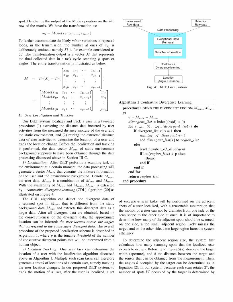
the user data. Mmix is a combination of Menv and Muser.With the availability of Menv and Mmix, Muser is extractedby a contrastive divergence learning (CDL) algorithm [20] asillustrated on Figure 4.
The CDL algorithm can detect one divergent data ofa scanned spot in Mmix that is different from the staticbackground data Menv and extracts this divergent data as atarget data. After all divergent data are obtained, based onthe consecutiveness of the divergent data, the approximatelocation can be inferred: the user locates across the anglesthat correspond to the consecutive divergent data. The overallprocedure of the proposed localization scheme is described inAlgorithm 1, where p is the tunable threshold of the numberof consecutive divergent points that will be interpreted from ahuman object.
2) Location Tracking: One scan task can determine thelocation of a user with the localization algorithm discussedabove in Algorithm 1. Multiple such scan tasks can thereforegenerate a streak of locations of a certain user, namely trackingthe user location changes. In our proposed DiLT system, totrack the motion of a user, after the user is localized, a set
Detection
Raw data
Contrastive
Divergence learning
Location
(Angle, Distance)
Exceptional Data
Removal
Data Transformation
Data Processing
Environment
Raw data
Fig. 4: DiLT Localization
Algorithm 1 Contrastive Divergence Learning
procedure FOUND THE DIVERGENT REGION(Mmix, Mevn,p)
d = Mmix −Mevn
divergent list = Index(abs(d) > 0)for x in (0, len(divergent_list)) do
if divergent list[x] >= 1 thennumber of divergent += 1add divergent list[x] to region list
elsereset number of divergentif len(region list) > p then
Breakend if
end ifend forreturn region list
end procedure
of successive scan tasks will be performed on the adjacentspots of a user localized, with a reasonable assumption thatthe motion of a user can not be dramatic from one side of thescan scope to the other side at once. It is of importance todetermine how many of the adjacent spots should be scanned:on one side, a too small adjacent region likely misses thetarget, and on the other side, a too large region hurts the systemefficiency.
To determine the adjacent region size, the system firstcalculates how many scanning spots that the localized userexpects to occupy. Referring to Figure 5(a), denote a the targetwidth (aperture), and d the distance between the target andthe sensor that can be obtained from the measurement. Then,the angles θ occupied by the target can be determined as inEquation (2). In our system, because each scan rotates 2◦, thenumber of spots W occupied by the target is determined by

d
!
…
W
target
Sensor
2W
(a) (b)
Fig. 5: Location Tracking
Equation (3).
θ = arctan(a/2
d)× 2 (2)
W =θ
2= arctan(
a/2
d) (3)
After the occupying size W is obtained, the system uses abinary back-off (BNB) algorithm to decide the adjacent regionsize as shown in Figure 5(b). Specifically, the system usesW 1 = 2W as the initial adjacent scan region size to identifythe new location of the target in the next scan task. If the targetis inside the adjacent region, the new user location can beidentified and the new adjacent region will be iteratively basedon the new location in the next tracking task. Otherwise, theadjacent region size is too small and the size will be doubledto W 2 = 2×W 1 to localize the moving target, and this BNBwill be repeated until the location of the user is identified.
IV. PERFORMANCE EVALUATION
We have extensively evaluated the performance of DiLT ina real environment.
A. Experiment Settings
The evaluation has been performed in a research laboratory(Robert Bell Hall Room 480). This room is complex and noisy,including large furnitures such as desks, tables, chairs anddesktops, as well as small devices such as mouses, cablesand bottles. This setting results in most reflection wavesfrom the large furnitures as the background, but with noisesfrom the small ones. A diagram of the experiment setup isillustrated in Figure 6. Small devices are not plotted on thefigure. The designed sensor system is placed on the desk 2. Inexperiments, four locations marked on the figure are tested.
B. Case#1: System Validation and Background Representation
Our first evaluation scenario is to validate the effectivenessof DiLT in using the distance to represent the static environ-ment background. In the experiment, the room environmenthas been scanned for ten loops by DiLT. No human orother mobile object exists in the room. With the sensor isincrementally rotated by 2◦ each time. One scan loop from 0◦
to 180◦ results in 91 pieces of data collected. The collected
Target 1
Target 2
Target 4
Target 3
Fig. 6: Experiment Environment
raw distance data are plotted in Figure 7(a). Each line presentsone scan loop in these ten loops. As we can observe from thefigure, the collected raw data contains a significant amountof noise that is indicated by the fluctuations along these lines.After the raw data are cleaned by the data processing algorithmof DiLT described in Section III-C1, the environment data isfinally shown clean as in Figure 7(b). This test indicates thatthe data processing to remove exceptional data is effective inusing distance to represent the environment.
0 20 40 60 80 100 120 140 160 180Angle Degree of Motor (Degree)
(a)
050
100150200250300350400
Dis
tance
(cm
)
Ultrasonic Scan Raw data for Environment
0 20 40 60 80 100 120 140 160 180Angle Degree of Motor (Degree)
(b)
050
100150200250300350400
Dis
tance
(cm
)
Ultrasonic Scan clean data for Environment
Fig. 7: Static Environment Background Representation
C. Case#2: User Localization
The second case evaluates the localization effectiveness ofDiLT. After the static background data is processed in thecase#1, DiLT starts a new scanning task to detect a humanobject in the room. In this test, the human object stays acrossfour different locations. When the user is in each location,DiLT scans for ten loops as it did for the static background.The collected raw sensor data of these four targets are firstprocessed to remove exceptional data, and then analyzed bythe localization algorithm as in Section III-D1 . Figure 8plots the localization results. The x-y plane shows the locationinformation in term of (distance, angle), and the z-axis is

the divergence between the data with user and the staticbackground data without the user. As we can observe, thereare four obvious divergent parts that indicate the four predicteduser locations (distance, angle) corresponding to the markedlocations in Figure 6.
Angle Degree of Motor (Degree)
0 20 40 60 80 100 120 140 160 180 Distance (cm)
2040
6080
100120
Divergent (cm)
0
20
40
60
80
100
120
140Target 1
Target 2
Target 3
Target 4
Fig. 8: Localization for Different Positions
D. Case#3: Location Tracking
This test case is to evaluate the capability of DiLT in track-ing the change of the user location. As discussed in SectionIII-D2, the location tracking is performed upon detection of theuser location in a serial of successive scan tasks by focusingon the adjacent region. We select the target#2 in Figure 6as an example to test the tracking algorithm. We collect thedata that has the user involved in four successive scan taskst1, t2, t3, and t4. The predicted locations in these four tasks areshown in Figure 9. From the figure, we can clearly observe thevariation of the user location at these four different moments,which reflects the trajectory of the user movement.
E. Case#4: Accuracy
In addition, we have evaluated the prediction accuracyof DiLT in localization. The accuracy indicates how closea predicted target location to its true location in the testroom. We have performed the test for 20 times with user atvarious locations. Table I shows the results of the accuracyand deviation of localization by DiLT.
TABLE I: Localization Accuracy
Parameter ValueAccuracy in percentage 76%
Max deviation ±30 (degree)Min deviation ±5 (degree)
Mean deviation ±12 (degree)
Angle Degree of Motor (Degree)
40 50 60 70 80 90 100 110 120 Time0 1 2 3 4 5
Distance
(cm
)
0
50
100
150
200
Time1
Time1
Time2
Time4
Fig. 9: Location Tracking
V. CONCLUSION
In this work, we design a distance based user localizationand tracking system, DiLT, which collects data by using com-modity off-the-shelf ultrasonic sensors for minimal invasion,while adopting signal processing techniques to reveal detaildynamics embedded in the sensed data. Through the mechani-cal beamforming supported by a rotational ultrasonic scanning,DiLT preprocesses and analyzes collected data to determinethe location of a user and track any location changes. Withextensive evaluation, DiLT is effective in using distance andangles to localize a user and track the motion trajectory.
REFERENCES
[1] Yoshifumi Nishida, Hiroshi Aizawa, Toshio Hori, Nell H Hoffman,Takeo Kanade, and Masayoshi Kakikura. 3d ultrasonic tagging systemfor observing human activity. In Intelligent Robots and Systems,2003.(IROS 2003). Proceedings. 2003 IEEE/RSJ International Confer-ence on, volume 1, pages 785–791. IEEE, 2003.
[2] Subhas Chandra Mukhopadhyay. Wearable sensors for human activitymonitoring: A review. IEEE sensors journal, 15(3):1321–1330, 2015.
[3] Yoshifumi Nishida, Toshio Hori, Shin-ichi Murakami, and HiroshiMizoguchi. Minimally privacy-violative system for locating human byultrasonic radar embedded on ceiling. In Systems, Man and Cybernetics,2004 IEEE International Conference on, volume 2, pages 1549–1554.IEEE, 2004.
[4] Debarun Chakraborty, Kangku Sharma, Ram Kishore Roy, HidamKu-marjit Singh, and Tulshi Bezboruah. Android application based mon-itoring and controlling of movement of a remotely controlled roboticcar mounted with various sensors via bluetooth. In Advances inElectrical, Electronic and Systems Engineering (ICAEES), InternationalConference on, pages 170–175. IEEE, 2016.
[5] Alessio De Angelis, Antonio Moschitta, Paolo Carbone, MassimoCalderini, Stefano Neri, Renato Borgna, and Manuelo Peppucci. Designand characterization of a portable ultrasonic indoor 3-d positioningsystem. IEEE Transactions on Instrumentation and Measurement,64(10):2616–2625, 2015.
[6] Christian Debes, Andreas Merentitis, Sergey Sukhanov, Maria Niessen,Nikolaos Frangiadakis, and Alexander Bauer. Monitoring activities ofdaily living in smart homes: Understanding human behavior. IEEESignal Processing Magazine, 33(2):81–94, 2016.
[7] Eun-Tae Ha, Tae-Kwan Kim, Dae-Kun Ahn, Soon-Hyun Jeong, Il-RoYoon, and Sung-Hyun Han. A stable control of legged robot based onultrasonic sensor. In Control, Automation and Systems (ICCAS), 201515th International Conference on, pages 1256–1258. IEEE, 2015.

[8] Yunfei Zhang, Clarence W de Silva, Dijia Su, and Youtai Xue. Au-tonomous robot navigation with self-learning for collision avoidancewith randomly moving obstacles. In Computer Science & Educa-tion (ICCSE), 2014 9th International Conference on, pages 117–122.IEEE, 2014.
[9] David Sloo, Nick Webb, Matthew L Rogers, Anthony M Fadell, JeffLee, Sophie Le Guen, and Andrew W Goldenson. Smart-home hazarddetector providing useful follow up communications to detection events,March 24 2015. US Patent 8,988,232.
[10] Masa Yamamoto, Naoko Ajiki, and Tetsuo Nakazawa. Ultrasonicdiagnosis arrangements for comparing same time phase images of aperiodically moving target, January 26 2016. US Patent 9,241,684.
[11] Jih-Gau Juang, Yu-Che Yang, and Jia-An Wang. Exploring an unknownenvironment using ultrasonic and infrared sensors. Sensors and Mate-rials, 28(9):991–1004, 2016.
[12] Fadel Adib, Hongzi Mao, Zachary Kabelac, Dina Katabi, and Robert CMiller. Smart homes that monitor breathing and heart rate. InProceedings of the 33rd Annual ACM Conference on Human Factorsin Computing Systems, pages 837–846. ACM, 2015.
[13] Kailiang Chen, Hae-Seung Lee, Anantha P Chandrakasan, and Charles GSodini. Ultrasonic imaging transceiver design for cmut: A three-level 30-vpp pulse-shaping pulser with improved efficiency and a noise-optimizedreceiver. IEEE Journal of Solid-State Circuits, 48(11):2734–2745, 2013.
[14] Faheem Ijaz, Hee Kwon Yang, Arbab Waheed Ahmad, and Chankil Lee.Indoor positioning: A review of indoor ultrasonic positioning systems. InAdvanced Communication Technology (ICACT), 2013 15th InternationalConference on, pages 1146–1150. IEEE, 2013.
[15] Israel Amir and Karuppiah Annamalai. Methods and systems forsynchronized ultrasonic real time location, December 10 2013. USPatent 8,604,909.
[16] Jaime Lien, Nicholas Gillian, M Emre Karagozler, Patrick Amihood,Carsten Schwesig, Erik Olson, Hakim Raja, and Ivan Poupyrev. Soli:Ubiquitous gesture sensing with millimeter wave radar. ACM Transac-tions on Graphics (TOG), 35(4):142, 2016.
[17] ET Akinlabi, M Shukla, SA Akinlabi, SB Kanyanga, and CM Chizyuka.Forming behaviour of steel sheets after mechanical and laser beamforming. Lasers in Engineering (Old City Publishing), 29, 2014.
[18] Peter Møller Hansen, Martin Hemmsen, Andreas Brandt, Joachim Ras-mussen, Theis Lange, Paul Suno Krohn, Lars Lonn, Jørgen ArendtJensen, and Michael Bachmann Nielsen. Clinical evaluation of syn-thetic aperture sequential beamforming ultrasound in patients with livertumors. Ultrasound in medicine & biology, 40(12):2805–2810,2014.
[19] William H Strickland and Robert H King. Characteristics of ultrasonicranging sensors in an underground environment. US Department of theInterior, Bureau of Mines, 1993.
[20] Sungjoon Choi, Eunwoo Kim, and Songhwai Oh. Human behaviorprediction for smart homes using deep learning. In RO-MAN, 2013IEEE, pages 173–179. IEEE, 2013.