disposal of concrete facilities · this report is the result of collaboration between the norwegian...
TRANSCRIPT

2
Contents
Introduction ............................................................................................................................................. 4
Summary ................................................................................................................................................. 5
Abbreviations .......................................................................................................................................... 7
1. Concrete facilities on the Norwegian shelf ...................................................................................... 8
Description of the concrete facilities ................................................................................................... 9
Condeep ........................................................................................................................................... 9
Other concrete structures ............................................................................................................... 11
2. Regulations .................................................................................................................................... 12
National regulations .......................................................................................................................... 12
International regulations and agreements .......................................................................................... 12
Disposal decisions and implementation ............................................................................................ 14
3. Refloating ...................................................................................................................................... 15
Technical feasibility .......................................................................................................................... 15
Safety ................................................................................................................................................. 23
Environmental conditions .................................................................................................................. 25
4. Transport ....................................................................................................................................... 27
Technical feasibility .......................................................................................................................... 27
Environmental aspects ....................................................................................................................... 27
5. Disposal on/by shore ..................................................................................................................... 28
Technical feasibility .......................................................................................................................... 28
Environmental matters ...................................................................................................................... 36
6. Abandoning concrete facilities offshore ........................................................................................ 43
Technical feasibility .......................................................................................................................... 43
Safety ................................................................................................................................................. 43
Environmental matters ...................................................................................................................... 45
7. Overall environmental assessments of various disposal solutions ................................................ 47
8. Presumed disposal costs ................................................................................................................ 48
9. References ..................................................................................................................................... 50
Appendix 1 General description of the concrete facilities on the Norwegian shelf .............................. 52
Appendix 2 Overview of potential environmental consequences of abandoning concrete facilities offshore, or disposing of the facilities onshore ..................................................................................... 58

3
Executive agencies: Norwegian Petroleum Directorate (NPD) Climate and Pollution Agency (Klif) Petroleum Safety Authority Norway (PSA)
Report date:
21 March 2012
Publisher:
Norwegian Petroleum Directorate
ISBN 978-82-7257-067-4
Authors: NPD: Erle Mæland Aasheim, Lars Asbjørn Nag, Tor Fadnes, Tom Andersen, Øystein Dretvik Klif: Hanne Marie Øren, Per Erik Iversen, Bent Barman Skaare, Bjørn A. Christensen PSA: Arne Kvitrud Title – Norwegian and English:
Disponering av betonginnretninger
Disposal of concrete facilities
Emneord: Disponering Betonginnretninger Miljø Sikkerhet
Subject words: Disposal Concrete facilities Environment Safety
Norwegian Petroleum Directorate P.O. Box 600, 4003 Stavanger Street address: Prof. Olav Hanssens vei 10 Telephone: +47 51 87 60 00 Fax: +47 51 55 15 71 Website: www.npd.no E-mail: [email protected]
Climate and Pollution Agency P.O. Box 8100 Dep, 0032 Oslo Street address: Strømsveien 96 Telephone: +47 22 57 34 00 Fax: +47 22 67 67 06 Website: www.klif.no E-mail: [email protected]
Petroleum Safety Authority Norway P.O. Box 599, 4003 Stavanger. Street address: Professor Olav Hanssens vei 10 Telephone: +47 51 87 60 50 Fax: +47 51 87 60 80 Website: www.ptil.no E-mail: [email protected]
Contact in the Norwegian Petroleum Directorate: Arne Holhjem
Contact in the Climate and Pollution Agency: Signe Nåmdal
Contact in the Petroleum Safety Authority Norway: Øyvind Tuntland

4
Introduction This report was prepared on the initiative of the Norwegian Petroleum Directorate (NPD), which invited the Petroleum Safety Authority Norway (PSA) and the Climate and Pollution Agency (Klif) to study technological challenges and aspects related to health, safety and environment in connection with disposal of concrete facilities on the Norwegian continental shelf. We are facing a period when disposal decisions will have to be made for the large concrete facilities built from 1973 – 1995. Little experience is available as regards removing and scrapping such facilities, and there is little direct data on which to base analyses. According to OSPAR decision 98/3 relating to disposal of disused offshore facilities, the basic rule is that all facilities shall be removed. However, applications may be filed for exemption from the prohibition against disposal at sea, for both permanent and floating concrete facilities. In light of the fact that the large concrete facilities have a number of common features as regards construction and technical condition, it was considered expedient to carry out a general review of the issues and challenges related to the various disposal solutions for these facilities. The report reviews refloating, towing the facility, demolition, scrapping and re-use. Allowing the concrete elements to remain in place is another alternative that has been studied. Three sub-assignments have been out-sourced; these have been carried out by Dr. techn. Olav Olsen a.s, Multiconsult AS and AF Decom Offshore AS. Norwegian Petroleum Directorate, Stavanger Climate and Pollution Agency, Oslo Petroleum Safety Authority Norway, Stavanger March 2012

5
Summary This report is the result of collaboration between the Norwegian Petroleum Directorate, the Climate and Pollution Agency and the Petroleum Safety Authority Norway. The report covers technical feasibility, as well as health, safety and environment challenges associated with various disposal solutions for disused concrete facilities offshore. During the period from 1973 to 1995, 14 concrete facilities were built and put in place for use in the petroleum industry on the Norwegian continental shelf. Two of these are floating, while the rest of them stand on the seabed. Construction of the facilities started at dock, followed by floating construction using so-called “glide”. Finally, the facilities were joined with a superstructure, or topside, before being towed to sea and placed at their final destination. According to OSPAR decision 98/3 relating to disposal of disused offshore facilities, the basic rule is that all facilities shall be removed. However, applications may be filed for exemption from the prohibition against disposal at sea, for both permanent and floating concrete facilities. Concrete facilities can thus be evaluated on a case-by-case basis. Disposal of the Ekofisk T and Frigg TCP2 concrete facilities have been processed to date, and abandonment in place has been approved by the Storting (Norwegian Parliament) following processing in OSPAR. Little experience is available, either in Norway or internationally, as regards other disposal solutions than abandonment of disused concrete facilities. The study shows that, while facilities built after 1981 have equipment intended for refloating, there will be a number of uncertainties linked to whether such operations can be carried out in a controlled manner. The facility could be weakened after spending such a long time offshore. Therefore, a thorough evaluation must be made of the overall condition, including reviews of structures and mechanical equipment needed for refloating. Depending on the composition of the seabed sediment, the concrete structures could be more or less stuck in the seabed sediments through suction. The factor of greatest importance for a successful refloating operation is probably a calculation of the extraction resistance of the skirts, along with the estimated weight of the facility. Removal of facilities is not without risk. At worst, an accident during preparations for the operations, refloating, transport or demolition could have serious consequences such as loss of life and negative impact on the environment. In connection with the process surrounding the disposal solution for the concrete substructure for the TCP2 facility on the Frigg field, HSE considerations were an important reason for the approval of abandonment of the facility in place. Bringing the concrete facilities to land for scrapping and material recovery entails the hazard of discharges to sea, and the demolition operations on land will generate dust and noise. Available area is needed, both on land and at sea, and conflicts with the local environment may arise. In addition, transport to land and disposal of the facilities on land will entail additional emissions of greenhouse gases. The advantages of landing are first and foremost that reinforcement bar (re-bar) and possibly also concrete can be recovered. If the facilities are removed, the seabed can be returned to its natural state, and there will be no restrictions on fishing and shipping in the area.

6
Re-using all or parts of the facility could be an alternative to scrapping and material recovery, for example as a bridge foundation or to establish artificial land. Abandonment of concrete facilities in place could be an alternative to landing, which can also entail safety advantages and be acceptable from a pollution perspective. Contaminated seabed areas around the facilities currently amount to a relatively small area, and this will gradually regenerate over time. Disrupting the cuttings piles to remove concrete facilities could impede this process. Abandonment will have little impact on fish populations, but could conflict with fishery interests due to the occupation of seabed area. Lights and navigation equipment must be installed on abandoned facilities, which mean that the risk of conflicts with ship traffic will be relatively small. This report and the accompanying background material can indicate that abandonment of the concrete facilities offshore could have fewer consequences for health and environment than landing the facilities for dismantling and material recovery. No direct comparison of the consequences has been made as regards safety.

7
Abbreviations
BFH Bromerte flammehemmere <brominated flame retardants>
CONDEEP Concrete deep water structure
DNV Det Norske Veritas
DMI Dansk Maritimt Institutt <Danish Maritime Institute>
GBS Gravity Based Structure (facility resting solidly on the seabed due to its own weight)
HAZID Hazard Identification
HSE Health, safety and environment
IMO International Maritime Organization
Klif Klima- og forurensningsdirektoratet <Climate and Pollution Agency>
NILU Norsk institutt for luftforskning <Norwegian Institute for Air Research>
MSF Module Support Frame
OD Oljedirektoratet <Norwegian Petroleum Directorate>
OSPAR Oslo-Paris-konvensjonen <OSPAR convention for the protection of the marine environment of the North East Atlantic>
PAH Polysykliske aromatiske hydrokarboner <polycyclic aromatic hydrocarbons>
PCB Polyklorerte bifenyler <polychlorinated biphenyls>
PSA Petroleumstilsynet <Petroleum Safety Authority Norway>
PDO Plan for utbygging og drift <Plan for Development and Operation>
TLP Tension Leg Platform (strekkstagplattform)
TOC Total Organic Carbon

8
1. Concrete facilities on the Norwegian shelf There are a total of 12 concrete facilities resting on the seabed on the Norwegian shelf. Ten of these are currently in operation, while two have been shut down and abandoned on site. The Ekofisk T and Frigg TCP2 concrete facilities have been abandoned on site after removal of the topsides. The ten operating concrete facilities on the seabed are located in the North Sea and the Norwegian Sea, as illustrated in Figure 1. Oseberg A, Troll A, Gullfaks A, B and C and Statfjord A, B and C are located in the northern part of the North Sea, Frigg TCP2 and Sleipner A are in the central part, while Ekofisk T with its barrier wall is in the southern part of the North Sea. Draugen A is in the Norwegian Sea. There are also two floating concrete facilities, Troll B and Heidrun A, located in the northern part of the North Sea and in the Norwegian Sea, respectively. See Appendix 1 for more information on the individual facilities. Also in the North Sea, there are 12 concrete facilities in the UK sector, one in the Danish sector, and two in the Dutch sector [1]. Of these, three facilities have been shut down and abandoned in place – the three Frigg facilities CDP1, TP1 and MCP-01 which are located in the UK sector. For Dunlin A and Brent B, C and D, all of which are located in the UK sector in the North Sea, disposal planning is underway. Statoil is currently working on an impact assessment for decommissioning and disposal of Statfjord A [2]. There are three land facilities in Norway that are currently in operation and have permission from the environmental authorities to scrap facilities from the petroleum activities: AF Miljøbase Vats, Scanmet (previously Scandinavian Metal AS) and Kværner Stord AS (previously Aker Stord). The location of these facilities is presented in Figure 1. In addition to these players, Lutelandet Offshore AS has also secured permission to operate a facility in Fjaler municipality in Sogn og Fjordane County.

9
Figure 1 Receiving facilities on land and concrete facilities on the Norwegian continental shelf
Description of the concrete facilities
Condeep Eleven of the 14 concrete facilities installed on the Norwegian shelf are Condeep facilities. Condeep (Concrete deep water structure) is a concrete, gravity based facility resting on the seabed. An overview of Condeep facilities is provided in Table 1. The last of these facilities built, and the largest of the Condeep-type, is Troll A. The facility stands in 302 metres of water, has a total height of 472 metres and a concrete jacket measuring 369 metres. This is the tallest concrete facility for petroleum production ever delivered anywhere.
The two first Condeep facilities were not designed for removal, while the following nine are (see Table 1). All are equipped with skirts that extend down into the seabed under each cell. The skirts on Troll A measure 36 metres, while the skirts on the earlier facilities extended 22 metres down. The cavities between the cells and the seabed are filled with concrete [3].

10
Facility Water depth Type Delivered Location
Frigg TCP2 104 m Condeep, 3 shaft Elf, 1977 North Sea, N Statfjord A 146 m Condeep, 3 shaft Mobil, 1977 North Sea, N Statfjord B 146 m Condeep, 4 shaft Mobil, 1981 North Sea, N Statfjord C 146 m Condeep, 4 shaft Mobil, 1984 North Sea, N Gullfaks A 135 m Condeep, 4 shaft Statoil, 1986 North Sea, N Gullfaks B 142 m Condeep, 4 shaft Statoil, 1987 North Sea, N Oseberg A 109 m Condeep, 4 shaft Norsk Hydro, 1988 North Sea, N Gullfaks C 216 m Condeep, 4 shaft Statoil, 1989 North Sea, N
Draugen 251 m Condeep, monotower Shell, 1993 Norwegian Sea
Sleipner A 82 m Condeep, 4 shaft Statoil, 1993 North Sea, N Troll A 303 m Condeep, 4 shaft Norske Shell, 1995 North Sea, N
Table 1 Overview of Condeep facilities on the Norwegian Shelf [4].
Figure 2 provides a chronological overview of all Condeep facilities ever built, 11 of which are in the Norwegian sector (as well as Heidrun A, which is a concrete tension leg facility).
Figure 2 Examples of concrete facilities [4].

11
A Condeep facility consists of:
- Steel or concrete skirt. The skirts are a continuation of the cell walls. They ensure sufficient anchoring in the seabed, and absorb horizontal wind and wave loads. The skirt length varies from one metre (Sleipner A) to 36 metres (Troll A), and is of considerable importance for the refloating process.
- Cylindrical cells with domes at top and bottom. The cells can be filled with water or function as storage for oil, in addition to ballast materials.
- Three or four shafts (just one on Draugen A) which run from the cells to above the sea surface. Often, there are two water-filled drilling shafts and one dry service shaft. The shafts form a base for a steel frame for the topsides.
Other concrete structures The first concrete facility in the North Sea was the Ekofisk tank, designed by the French engineering firm DORIS. The Ekofisk tank was installed in 1973 and put to use in 1998. The Ekofisk tank has now been cleared of all deck modules, and abandoned in place. DORIS has designed several gravity-based facilities in the North Sea, including on the Frigg field (CDP1 on the UK side). A large circular bottom frame with a single shaft and ”Jarlan” breakwater wall is typical of the DORIS design[4]. Due to subsidence of the seabed on Ekofisk, an additional protective wall, the Ekofisk barrier, was installed in 1989 on the outside of the original breakwater. The two floating concrete facilities on the Norwegian shelf, Troll B and Heidrun A, were both installed in 1995. Kværner Concrete Construction supplied the jacket for Troll B, which was the first semi-submersible concrete facility. Norwegian Contractors supplied the jacket for Heidrun A, which is a floating concrete tension leg platform.
After the last Norwegian concrete gravity-base facility was built, several such facilities have been built in other locations. These include Hibernia (1997) in the Canadian sector, as well as Sakhalin PA-B (2005) and Lunskoye A (2005) in the Russian sector.
12
2. Regulations Disposal of petroleum facilities is governed under the (Norwegian) Petroleum Act. The central international framework is set by the OSPAR Convention and the guidelines of the International Maritime Organization (IMO). The petroleum activities are governed by the petroleum regulations, while maritime activity and maritime operations are governed by maritime regulations. The line between petroleum activity and maritime activities can be difficult to ascertain, but it is important. The importance of this division is highlighted below. When facilities are removed, all work done on or with the facility on site will be defined as petroleum activity. It may also be necessary to use vessels during the removal operation. As regards vessels, only petroleum activity is governed by the petroleum regulations. In other words, only the removal work the vessel participates in is governed by the petroleum regulations.
National regulations Pursuant to Section 5-1 of the Petroleum Act, licensees must submit a decommissioning plan two to five years before a production licence, or consent for installation and operation of a facility expires or is relinquished, or use of the facility is terminated permanently. Section 43 of the Petroleum Regulations deals with the content of a decommissioning plan. The decommissioning plan shall consist of a disposal part and an impact assessment part. The disposal part shall include proposals as regards continued production or shut down of production and suggested disposal of the facilities. Such disposal can include continued use in the petroleum activities, other use, complete or partial removal or abandonment. The required documentation as regards the safety and working environment area of decommissioning plans follows from the regulations relating to health, safety and the environment in the petroleum activities and at certain onshore facilities (Framework Regulations), Section 30. In the plan, the licensee shall examine various disposal alternatives. The decommissioning plan shall recommend a comprehensive solution. The regulations do not stipulate practical requirements as regards the actual removal. Receiving facilities for disused offshore facilities on land must have permits under the (Norwegian) Pollution Control Act. In addition, other activities linked to disposal of the facilities may require special permits under the Pollution Control Act, including e.g. removal/transfer of drill cuttings, discharge of ballast water and other necessary work to prepare the facility to be brought ashore.
International regulations and agreements In addition to national regulations, the decommissioning plan must be drawn up so as to take into consideration the requirements found in international regulations. This particularly relates to the OSPAR Convention and the IMO guidelines.

13
OSPAR decision 98/3[5] on the disposal of disused offshore facilities entered into force on 9 February 1999 and sets the framework for which disposal alternatives are acceptable for various types of offshore facilities. The resolutions under the OSPAR Convention are binding for the EU countries, Switzerland, Iceland and Norway, and are intended to protect the marine environment in the north-eastern part of the Atlantic Ocean. The OSPAR decision entails that dumping and abandoning all or parts of disused offshore facilities in marine areas is prohibited. However, the decision does not include:
- parts of a facility that are beneath the seabed - concrete anchor foundations that do not present an obstacle to fisheries - drill cuttings - pipelines
National authorities can consent to exemptions from the OSPAR decision for the respective facilities. Exemptions can be granted for all or parts of facilities following consultation with the other OSPAR countries if there are weighty reasons in favour of alternative disposal. Exemptions relate to:
- jacket bases for steel facilities weighing more than 10 000 tonnes in air and deployed prior to 9 February 1999
- gravity-base concrete facilities - floating concrete facilities - concrete anchor piles that disrupt or will presumably disrupt other lawful use of the
sea - any other facility when exceptional and unforeseen circumstances that are due to
structural damage or deterioration, or other causes that entail similar difficulties, can be proven
It emerges in Appendix 2, Item 8c of the OSPAR decision that consideration shall be given to safety in connection with removal, but the Convention does not stipulate practical requirements for the actual removal operation. Reference is also made to Storting Proposition No. 8 (1998-1999), Chapter 5, Decision on disposal of disused offshore facilities, adopted at the OSPAR Convention’s meeting of ministers on 23 July 1998. In addition to OSPAR, the UN’s Law of the Sea Convention, Article 60, Item 3 [6] and the IMO guidelines in resolution A.672 (16) [7] are of significance for disposal. OSPAR’s recommendation 2006/5 [8] sets criteria for handling oily cuttings on the seabed. These criteria set limit values for leaking of oil to the water column (maximum 10 tonnes/year) as well as lifetime and spread of the cuttings piles (500 km2/year). The IMO guidelines (MSC/Circ. 490, 4 May 1988) are instructive guidelines whose primary purpose is to safeguard considerations for shipping. Pursuant to these guidelines, facilities shall be removed down to a minimum depth of 55 metres below the sea surface. Facilities that are in less than 75 metres of water, and that have a structural weight of less than 4000 tonnes, shall be removed. For facilities deployed after 1 January 1998, the stated depth is increased to

14
100 metres. After the arrival of the OSPAR Convention, the IMO requirements are less relevant in the north-eastern Atlantic since the OSPAR requirements are generally stricter. One important exception from this is that the IMO guidelines presuppose removal of the facilities down to a certain depth, while abandonment under the OSPAR Convention does not set such requirements. Marking is sufficient here.
Disposal decisions and implementation The Ministry of Petroleum and Energy makes a disposal decision based on the decommissioning plan, cf. Section 5-3 of the Petroleum Act. The decision need not correspond to the plan the licensees have presented, as this is not an approval of the decommissioning plan that is adopted, but rather an independent resolution. The section also governs implementation of the disposal decision and stipulates responsibilities. Furthermore, the Ministry can initiate measures on behalf of the responsible party if the decision is not implemented within a stipulated deadline. If the disposal solution includes abandonment after an advance OSPAR consultation, the Storting (Norwegian Parliament) will make the decision. Under Section 5-3 of the Petroleum Act, licensees and owners are obliged to ensure that disposal decisions are carried out, unless the Ministry of Petroleum and Energy determines otherwise. This obligation applies even if the disposal decision is made or will be implemented after expiration of the licence. Submission of a decommissioning plan does not release the licensee or owner from obtaining approval, permission or consent pursuant to other statutes or regulations. Reference is also made here to Section 1-5, first subsection of the Petroleum Act. The licensee must, for example, obtain consent from the Norwegian Petroleum Directorate prior to final shutdown of the operations on a facility or a field and prior to implementation of final disposal pursuant to a disposal decision, cf. Section 30a of the Petroleum Regulations. As regards the HSE area, the consent requirement is stated in Section 25 of the Management Regulations. Moreover, the operator is obliged to consider whether activities will take place that require permission under the Pollution Control Act, and must apply to the pollution authorities for such permission. Disposal of facilities will normally take place within different regulatory regimes. Therefore, which regime applies must be considered in relation to the respective activities.

15
3. Refloating In connection with landing for scrapping and possible re-use of concrete structures, it will be necessary to make the structures floatable and movable.
Technical feasibility Concrete facilities have many separate buoyancy cells, and we must ensure that every single one of these is tight so as to prevent loss of stability through leakage between the cells or to sea. All openings in the drilling shafts must be closed so that the water can be pumped out and buoyancy achieved. The stability of the structure must be computed. Among other things, this will determine how much of the topsides must be removed prior to refloating. Furthermore, the weight of the facility must also be calculated, including the weight of sand, wax precipitation, etc. that have accumulated during the period of use. The weight of the concrete between the facility and the seabed must also be estimated. One of the main challenges associated with refloating is that the facility may be stuck in the sediments. A release process is very difficult to control, and there is a risk that the facility could rise abruptly when it finally comes loose. The pressure under each cell skirt must be checked, and communication must be assured between the skirts so as to avoid underpressure in individual chambers. First-generation concrete facilities are equipped with pipe connections to most of the skirt chambers, but not all of them. In any event, pipe connections must be established to all areas in the foundation, in order to release this from the seabed. Experience has been gained in recent years with removal of bucket foundations for jack-up facilities on the Norwegian shelf. Since we do not have experience with large concrete foundations, the jack-up foundations are as close as we get. These are also stuck to the seabed through suction, like the skirts, and have an area that is comparable to a cell. Releasing the facilities from the seabed The facilities can be released by pumping water into the skirt chambers. Necessary overpressure will be one to three bars, depending on sediment type and skirt configuration. Higher local pressure is calculated for older concrete facilities. A precondition for the success of such an operation is that the overpressure does not leak out through permeable channels/fractures in the sediments. This could possibly be offset by having substantial pumping capacity. When the skirts come up to the sea surface, the pressure will disappear under the individual skirt. In this phase, pressure build-up under the remaining skirts will have to continue while ballast water is pumped out to overcome remaining friction. If the friction is high, there could be strong, abrupt upward movement when the facility is completely released. If good control is not maintained over the deballasting, there could be a risk of the jacket hitting the seabed, causing breakage on the edges of the skirt/cell. The effect of cyclical loads was tested in an experiment on Gullfaks C. The skirt was raised and lowered 10 to 20 centimetres five times, and a 50 % reduction in side friction was measured. This is important since it is desirable that as much as possible of the topside weight
16
is removed onshore. An assessment of whether a cyclical approach can reduce the need for increased buoyancy in the release phase should therefore be implemented. Similar solutions have been used e.g. in the Gulf of Mexico on jack-up facilities that have sunk quite far down into normally consolidated clay [4]. If the condition of the sediment mass is such that it cannot provide sufficient jacking pressure, a sealing compound can be pumped into the skirt chambers, forming a seal over the permeable soil so that the jacking pressure can be increased. If one succeeds in releasing the facility from the seabed, the next challenge is that concrete or sediments under the facility can follow the facility from the start, and subsequently come loose. This could cause the facility to float up in an uncontrolled manner, or to lose stability. There is also a risk that this mass could fall off during the tow operation; which could at worst lead to breakdown or damage to other facilities, primarily pipes. Towing over subsea templates and pipelines should be avoided to the extent possible. Procedure The refloating process mainly encompasses the following steps:
- planning, inspections and tests - preparations offshore; removal of drill cuttings and sediments, possible removal of
parts of the topsides, closing conductor openings and other openings, installation and testing of refloating system, etc.
- deballasting to neutral buoyancy over a period of time to reduce the effective stresses in the seabed
- hydraulic jacking and further deballasting until the skirts are released from the seabed - deballasting to transport draught before the facility is towed to its destination
It will be possible to stop the refloating operation up to a certain point in the process, probably right before the skirts are released from the seabed. A continuous evaluation must be made as to whether or not the conditions are such that it is prudent to continue. Planning/preparations There are many elements and risk factors that must be studied before work starts offshore, such as structural aspects, maritime systems, as well as geo-technical and mechanical condition. A number of studies and tests must be performed to reduce uncertainty in the assumptions used for estimates. Which studies and tests must be carried out immediately will be determined in early-stage engineering. Gathering information is also a large part of this phase. Relevant areas for offshore studies:
- volume of debris and drill cuttings on top of the domes, in tri-cells and on the seabed - sediment level in the cells - volume of drill cuttings in the drill-shafts - weight and position of elements on the facility deck - marine fouling - cracks in the concrete

17
- leak rates through the concrete, particularly for shafts that have been filled with water - condition of towing and mooring fastenings - mechanical equipment and pipelines - new geotechnical surveys of the seabed around the facility
Relevant (full)-scale tests:
- test of sealing method for sealing conductor openings - in-situ test of pressurisation in all skirt compartments - test of extraction resistance in highly over-consolidated sediments
With information from initial surveys and tests, detailed engineering of the refloating operation can begin. Some of the most important factors to verify include the weight estimate and available buoyancy volume. Challenges associated with weight are described in more detail below, under the weight heading. Together with extraction resistance, facility weight is of great importance as regards which other measures must be implemented in order to carry out a successful refloating operation. Activities included in the engineering phase
- review of applicable regulations and standards - weight, stability and buoyancy calculation - preparation of plan for potential removal of drill cuttings and other substances - verification of structure’s integrity, new analyses for load situations in the event of
refloating - verification of mechanical systems, preparation of plan for installing new equipment
or replacing the old - determination of geo-technical conditions
- calculate pulling resistance - assess facility stability in deballasted condition - estimate deconsolidation period - determine permitted hydrostatic base pressure during refloating - assess need for potential additional load on the seabed around the facility
- planning of maritime operations - assess need for instrumentation
Depending on the weight calculation result, it may become necessary to remove additional weight from the facility. This weight could come from the topsides, sediments in the cells or drill cuttings in the shafts and on the cells. Weight Considerable weight has been added to the facility since it was installed. This includes, for instance, grouting under the lower domes, conductor pipes, J-pipes, mechanical equipment and new modules on the deck. The weight can be determined with greater accuracy after the initial surveys, but there will still be some uncertainties that cannot be eliminated. The two most important are how much grout (cement mortar) is stuck under the lower domes and the size of potential sediment plugs in the skirt compartments.

18
Elements in the weight calculation:
- concrete - mechanical equipment - permanent ballast in the cells - water ballast in the cells - sediments in the cells - drill cuttings in drilling shafts - drill cuttings and other debris on top of the domes and in tri-cells - marine fouling - grouting under the lower domes - sediment plugs - water absorption in concrete
The weight of the facility is crucial as regards both stability and necessary buoyancy. A low centre of gravity in the structure is beneficial for stability, so the metacentric height, the distance between the centre of gravity and metacentre, is positive with a necessary safety margin. Excessive weight on the facility deck is therefore negative in a stability context. A minimum metacentric height is determined in the stability calculation. Here you must calculate stability with and without grout and sediment plugs. See illustration of the stability principle in Figure 3.
Figure 3 Stability, G=centre of gravity, M=metacentre and B=buoyancy centre of gravity. The metacentric height is the vertical distance between the centre of gravity (G) and metacentre (M). The facility is stable when the centre of gravity is below the metacentre [4].
Available buoyancy is contingent upon the number of functional cells and whether the drilling shafts can be closed, and then how low they can be deballasted. The permitted ballast level is determined based on concrete capacity. A low ballast level results in a major differential pressure, which can partially be compensated for by using the gas pressure in the cells. If too little buoyancy is available in relation to the weight of the facility, it might be relevant to assess use of external buoyancy chambers. The available buoyancy limits the total weight, while stability limits weight distribution.

19
Closing conductor openings One of the most important and challenging tasks as regards practicality involves closing the conductor openings. The conductors are guide tubes for drillstrings, and they run from the top of the drilling shafts, down through sleeve tubes in the lower dome, see Figure 4. The number of conductor openings varies, but on several facilities the number is approximately 40-50 distributed in two shafts. So a considerable number of openings need to be closed, and they are located in a relatively inaccessible area. Most of the work will take place under water, and if the conductor pipes have to be removed, many heavy lifts are involved. If a crane with the sufficient capacity is not available, it will be time-consuming to cut and lift all pipe sections. Many different solutions for closing the conductor openings have been proposed in previous studies. They can generally be divided into three categories:
- plugging in the conductor pipe - plugging outside the conductor pipe - casting a new bottom
There are advantages and disadvantages to all of the solutions, but regardless of what is chosen extensive testing is required. The seal must be able to withstand significant water pressure (over 300 metres on Troll A), and a leak could have serious consequences. Figure 4 shows a mechanical plug in the sleeve tube of the conductor opening and two alternatives for casting a concrete plug under the dome.
Figure 4 Mechanical plug, plug from "umbrella casting" and concrete bag [4].
If the condition of the sleeve tube is satisfactory, mechanical plugs that can withstand high pressure currently exist. One of the advantages of placing the plug on the outside is that the water pressure from the outside ensures the plug stays in place, so the opening will hopefully remain watertight. However, this requires excavation under the dome, and each conductor opening must be closed separately. Figure 5 shows an example of a new bottom. A steel plate covers the entire dome, anchored through the conductor openings. Drill cuttings must be removed before installing the plate, and it may be difficult to achieve a watertight connection with the concrete. The advantage is that there will only be one closing operation and test per shaft.

20
Figure 5 Closing with steel plate [4].
There are multiple elements that need to be considered when choosing a solution. If there are weight problems, it might be appropriate to choose a solution where the conductors are removed as each pipe weighs about 650 kg/m. For the Statfjord facilities and Gullfaks A and B with 42 well slots in each facility, the total conductor weight will be about 4 000 tonnes per facility. This is about 8-10 per cent of the deck weight. Topsides When carrying out refloating, it is reasonable to assume that the least cost-demanding method for transporting the topsides to land is using the concrete jacket. As considerable weight has been added through installation of mechanical equipment and modules offshore, it might still be necessary to remove some of this before refloating. Most facilities have a “Module Support Frame” (MSF) type deck foundation, where a steel frame rests on the concrete shafts and supports the different modules. It is possible to lift off modules and transport them to shore using suitable lifting vessels. However, some facilities have integrated topsides. This entails that the process equipment is an integrated part of the topsides structure, which results in a lower topside weight. This also makes dismantling more difficult and time-consuming. Regardless of the type of topsides, it will be beneficial for the topsides’ centre of gravity to be located as centrally as possible over the shafts, and as low as possible. You need a detailed overview of all weight on the topsides and the placement of this. After the permitted total weight has been determined, you can assess what to potentially remove from the facility topsides. It will be useful to keep some modules through the removal process. This applies to the living quarters for instance. It is also beneficial to keep a work deck with cranes and other equipment, depending on what work is planned offshore. Releasing the skirts from the seabed and “pop-up” The most critical phase of the refloating operation is the moment when the skirts are released from the seabed. Since it is difficult to create pressure in the skirt chambers when not much is left of the skirts in the seabed, the final pulling force must be created through positive buoyancy. It is therefore important to control the weight of the facility, so the positive buoyancy of the release does not lead to an uncontrolled rise to the surface. The height of the first movement is critical, before the facility stabilises at an equilibrium level, see Figure 6.

21
Figure 6 Example of calculated vertical dynamic movement of a concrete facility when it loosens from the seabed [4].
If the cells have gas pressure to reduce the differential pressure against the tri-cells, it is crucial that this pressure does not become so high that internal overpressure occurs when the facility rises. To calculate the rise, you must generally consider three factors:
- remaining pulling power when it is no longer possible to create hydraulic pressure - weight uncertainty for the facility - margins for handling different variations surrounding the cement mortar and/or that
the sediment plug falls off immediately after release It will be detrimental for the concrete in the upper domes if tension occurs over the entire cross-section. This can happen with internal overpressure. Depending on the size of the overpressure, the damage could be anything from scrapes to loss of the facility. One measure to limit excessive positive buoyancy is to “weigh” the facility during the process of pulling out the skirts. This can, in simple terms, be done be stopping the hydraulic jacking and measuring pressure change and vertical movement. Stability during rise From deballasting until neutral buoyancy in the deconsolidation phase, the facility has less resistance towards wind and wave loads. This must be taken into consideration when determining a weather window for the operation. The permitted wave height and wind speed for different parts of the operation are determined here. The deconsolidation phase could, for instance, take place from the start of the summer season, while the actual release has a shorter duration and is performed in a period with safe and good weather forecasts. When the facility has been released from the seabed, floating stability must be calculated. DNV’s rules for marine operations state that “metacentric height (GM) corrected for free surface effect should be at least 1 m. The stability should be positive to a heel angle of 15º beyond equilibrium.” Exemption from this requirement can be granted for temporary phases. The field cessation study for Draugen A describes model experiments performed at the Danish Maritime Institute (DMI), which is now part of Force Technology. A 1:50 model of Draugen A was tested in the tow tank to assess floating stability during refloating. The conclusion was that the facility has sufficient floating stability, even if all or parts of the cement mortar fall off during the process. The tank tests also showed that the facility was
22
more stable during refloating than expected due to energy loss from turbulence around the concrete box during vertical movement through the water [4]. Interrupted operation During preparations for the refloating operation you must define a “point of no return”, where the refloating must be carried out if you made it to that point. Until this point, you must continuously assess whether the conditions are suitable for successful refloating. There are several steps during where it might emerge that you must stop the operation. If this takes place during the actual refloating, there must be a “plan B” for further action after the operation has been cancelled.

23
Safety Phases in connection with removal of concrete facilities Removal is in many ways a reversed installation and operations phase. After the decision has been made to shut down a facility, the concrete facility will be removed and there will no longer be a safety zone when it has been released from the seabed or the final anchor is removed. This assumes that it is an independent concrete facility and there are no other facilities within the safety zone. Risk for personnel and equipment Before making a decision regarding disposal of a facility, extensive planning work with assessment of relevant removal scenarios will have been carried out. The decision must be anchored in a risk analysis, where you define the unacceptable probability of different degrees of failed operations. The degree of failure can roughly be divided into:
- total loss - failed refloating, but still possible to dispose of the facility in other ways - partially failed refloating, but with opportunity to try again following certain
modifications All hazards and uncertainties that can impact the risk of a failed operation must be identified through a so-called HAZID study (Hazard Identification). HAZID is a qualitative analysis, while you subsequently carry out a quantitative analysis by calculating the probabilities of a failed operation. There will always be uncertainties when assessing the probabilities in the risk analysis, but the regulations require such an analysis [9]. Then you can identify the areas with highest risk, and where the potential for reducing risk is greatest. Removal of facilities is not risk-free. In the worst case, an accident during preparations for the operations, refloating, transport or dismantling could have serious consequences such as loss of life and negative impact on the environment. There are also financial consequences. The processing of the disposal solution for TCP2’s concrete substructure on the Frigg field shows that HSE considerations were an important factor in the decision to abandon the facility on site. In the press release from the Ministry of Petroleum and Energy dated 9 January 2004, the following assessments were addressed: “Based on an overall assessment where consideration has been given to technical feasibility, safety for personnel, the environment, costs and effects for other users of the sea, the Government recommends that the disposal solution for the TCP2 concrete jacket on the Frigg field be abandonment on site. Abandonment has been justified by a removal operation entailing an unacceptably high risk for loss of human life and other damage. The assessment is based on risk analyses carried out and verified by independent technical expertise. In addition, a removal operation is considerably more expensive.” If concrete facilities are abandoned, you must also carry out structural analyses of the facility without a deck. There will be a different rigidity in the shafts without a deck, and you must ensure the facility will remain safe. A risky situation could occur if the shaft suddenly cracks in the stillwater zone, and becomes a skerry for ship traffic. The concrete facilities must also

24
be safe for personnel who will go on board to maintain the light signals for many years in the future. Technical regulations and standards within the HSE regulations
It is assumed that the actual concrete structure will be unmanned during the removal.
The oldest concrete facility on the Norwegian shelf is the Ekofisk tank that was installed in 1973. The others were installed in the period up to Troll A which was installed in 1995. As a consequence of this, the concrete facilities were all built according to different regulations.
New technical guidelines have not generally had a retroactive effect on existing facilities. The regulations applied depend on when the “main plan”1
The technical regulations contain requirements for the concrete structures that must also be fulfilled during the removal process. Some of the standards referenced also have possibilities for lower safety factors if collapse of the facility will not result in risk of injury to personnel, damage to the environment or major socio-economic consequences.
or plan for development and operation (PDO) was adopted. The applicable management and activities regulations must be used as a basis [10] for management systems and activities on and with the facilities.
The Ekofisk tank was installed before the first technical regulations had been prepared, and a set of specifications from the builder was most likely used as a basis. The Management Regulations and Activities Regulations were applicable during disposal of the tank. Otherwise, the general prudence requirements in today’s regulations apply.
In 1977, regulations for load-bearing structures entered into force. These regulations stipulate requirements for load and strength calculations on concrete structures, but do not contain specific removal requirements. However, the general requirements must be considered valid during removal as well. The regulations were in effect until 1984.
In 1984, regulations for load-bearing structures entered into force. These regulations contain a requirement for load and strength calculations on concrete structures, and Item 2.2 stipulates that it must be possible to remove the structures. The regulations were in effect until 1991.
New regulations on load-bearing structures came into force in 1991. These regulations also contain requirements for load and strength calculations on concrete structures. The removal requirement is repeated in Section 18. These guidelines were in effect until 2001. The guidelines for Section 18 also stipulate that removal must be assessed in the engineering phase. A comment to the provision indicated that, in practice, it will not be possible to remove, for instance, piles that were driven into the seabed, and this was acceptable as the removal requirement is connected to international law requirements that ensure fishery and ship traffic interests and protect against littering of the seabed [11]. Structure parts that remain must then be designed such that they can be removed in such a scope that they cannot harm or hinder other activity.
1 A main plan was the plan made before the term PDO was introduced.

25
Environmental conditions Disturbing drill cuttings and base sediments Several facilities on the Norwegian shelf have significant accumulations of drill cuttings nearby that have been there since the 1980s when discharges of oil-based cuttings were permitted. Nearly all discharges of oil-based cuttings ceased in the first half of the 1990s due to regulatory requirements. In its recommendation from 2006, OSPAR stipulated criteria for abandonment of cuttings piles. These indicate limit values for leaking of oil to the water column (maximum 10 tonnes/year), as well as lifetime and spread of the pile (500 km2/year). A DNV report prepared for OLF in 2008 [12] concludes that the drill cuttings piles on the Norwegian shelf in all likelihood satisfy OSPAR’s abandonment requirements, and that further assessment of measures is unnecessary. This presumes that the piles are not disturbed. Based on monitoring data and other available data, it has been proven that the piles have reduced over time, and as of 2008, the DNV report attempts to calculate the remaining volume. For instance, the concrete structures on Gullfaks, Statfjord and Oseberg still have relatively large piles on the seabed, see Table 2.
Facility Water depth Drilling fluid Total discharges On seabed Estimated M three types m3 % present m3
Gullfaks A 134 w.o.s 128,787 40 51,515 Gullfaks B 143 w.o.s 139,771 35 48,920 Gullfaks C 216 w.o 118,100 25 29,525 Oseberg B 103 w.o.s 102,018 35 35,700 Statfjord A 146 w.o.s 64,466 35 22,563 Statfjord B
144 w.o.s 67,143 35 23,500 Statfjord C 146 w.o.s 63,630 35 22,271
Table 2: The table is a revised excerpt from an overview table and the drilling fluids are W = water-based, O = oil-based and S= synthetic, respectively [12].
We do not have much information on what these piles look like and what they contain as of today. If the concrete facilities will be refloated, a thorough assessment of the cuttings and sediments that need to be collected/ moved before refloating must be carried out. In the event of potential refloating and removal of the concrete structures, the handling of drill cuttings around and potentially on top of the cells will be a practical challenge. Suction dredging and displacement of cuttings/sediments have been carried out previously in connection with disposal. You need to apply for a permit from Klif for these types of operations. The alternative is loading the drill cuttings in boats/tanks and transporting this to shore.

26
Emissions to air
A refloating operation will, necessarily, as with the rest of the landing process, entail that many vessels will be operating around the facility. This will result in emissions to air, consisting primarily of CO2, SO2 and NOx. Accidental spills
As described above, refloating of concrete facilities involves safety-related challenges. In this connection there will also be a risk of accidental chemical and oil spills to sea.

27
4. Transport Most concrete facilities are designed to stay afloat even with water-filling of one cell. Water-filling in a shaft can lead to the facility sinking. Technical feasibility The following considerations must be assessed in connection with a towing operation:
- The towing route must be verified in advance for draught and width - Weather criteria for refloating and the tow must be determined in advance - A weather window for the duration of the tow must be determined before towing can
start - The operation must be documented in detail. The procedures must specify what needs
to be done if the weather conditions become worse than permitted. - Certificates, tests and potential classification documents for both equipment and
personnel must be available before start After the facility has been released from the seabed, surveys of the facility must be carried out before the tow starts. The most important is carrying out an inspection of the entire facility, particularly the underside, in order to assess the significance of remaining grouting or sediments. Weight and stability inspections are also relevant. As mentioned under refloating, the mass under the lower domes could fall off during lifting and towing. This can impact stability, platform movements and buoyancy, as well as constitute a risk for crossing pipelines. Shallow water that will be passed during transport must be taken into consideration in the stability calculation in the planning phase. This can limit the deck weight. For instance, the Gullfaks C facility was deballasted eight metres during the tow through Langenuen, a shallow strait in the approach to Stord, in relation to offshore draught. When the facility has been deballasted to towing draught, the necessary equipment has been disconnected, the towing boats are connected and the control of the facility systems has been transferred to the head boat, the tow can commence. It is assumed that the old towing fastening points can be used or replaced, and it will thus be possible to use the same towing configuration as during the original tow. It is assumed that the facility is unmanned during the tow. All pipelines must be crossed perpendicular during the tow, so the facility uses as little time as possible crossing the pipelines. Environmental aspects As with the rest of the landing process, transport of the jacket to shore will result in emissions to air. There are also possibilities for accidental spills from towing vessels and other involved vessels that are present during the transport, but not beyond what is common for normal shipping traffic. Some marine fouling can be expected to fall off while the facility is being towed. This is not considered significant in an environmental context, as the fouling (which will not be polluted under normal conditions) will return to the natural environment it came from and be spread over a large area.

28
5. Disposal on/by shore Reuse of the entire concrete structure or concrete elements, scrapping/crushing and recycling of concrete and re-bar can be possible disposal solutions. However, such disposal will entail both safety-related and environmental challenges.
Technical feasibility There are currently three plants in operation in Norway with permits to receive large disused facilities from the petroleum activities for scrapping and material recycling, AF Miljøbase Vats, Scanmet (formerly Scandinavian Metal AS) and Kværner Stord AS (formerly Aker Stord). Lutelandet offshore AS has been granted a permit to start a new plant in Fjaler municipality in Sogn og Fjordane. None of these facilities have previously received large concrete facilities for scrapping and material recycling, and the plants are not fitted for this at the moment. There are therefore no concrete experiences and documentation regarding environmental effects of such final disposal. The experiences gained in connection with receiving and final disposal of steel jackets and sections from facility decks, however, could be relevant to a certain extent. An alternative possibility could be to re-establish plants where concrete facilities were built. An overview of possible locations for bringing the facilities to shore are summarised in the report from AF Decom Offshore AS [13]; Åndalsnes, Stord, Vats, Ålfjorden/Dommersnes and Loch Kishorn, respectively. After the shafts and parts of the cells have been removed it will be necessary to cut up the rest of the facility in a dry dock. There are already some dry dock locations that can cover this need, such as Hanøytangen in Hordaland and Loch Kishorn in Scotland. Alternatively, new dry docks can be constructed at suitable locations. Below we provide a short overview of environmental aspects related to landing concrete facilities for scrapping and final disposal. Technical aspects in connection with onshore dismantlement
Following the towing operation to a deep water location, the concrete facility will be anchored up and rigged for dismantling work. The different scenarios defined in the table below could be applied alone or in combination with others.
Concrete facilities with the corresponding strength and reinforcement density as the Condeep facilities have not been dismantled before. Many large and heavy concrete facilities have been dismantled onshore, such as bunker structures and large foundations in industrial areas. It is common for such structures that the dismantling methods do not need to take special consideration to the concrete strength or structural integrity. However, these will be crucial factors for disposal of concrete facilities.
A dismantling project will be a major task and require extensive preparation. Significant requirements are stipulated for organisation, planning, rigging and implementation of the work to maintain HSE considerations and rational production work.
29
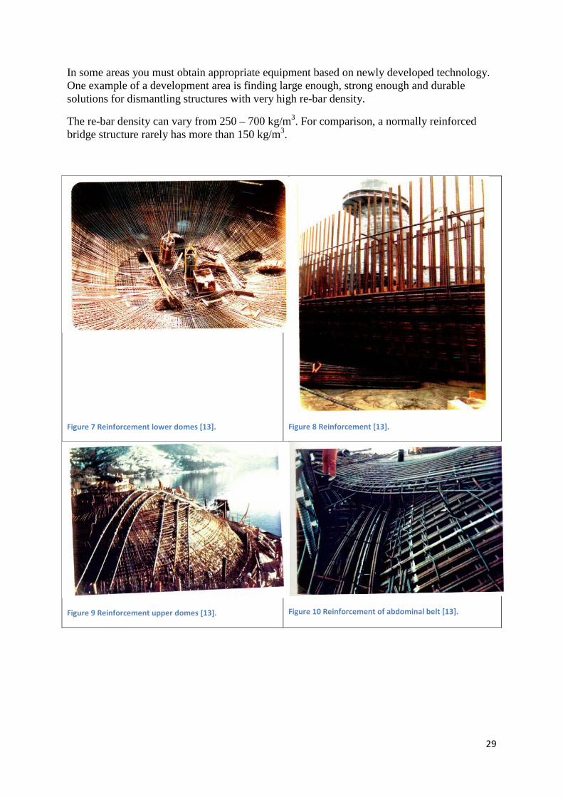
In some areas you must obtain appropriate equipment based on newly developed technology. One example of a development area is finding large enough, strong enough and durable solutions for dismantling structures with very high re-bar density.
The re-bar density can vary from 250 – 700 kg/m3. For comparison, a normally reinforced bridge structure rarely has more than 150 kg/m3.
Figure 7 Reinforcement lower domes [13].
Figure 8 Reinforcement [13].
Figure 9 Reinforcement upper domes [13].
Figure 10 Reinforcement of abdominal belt [13].

30
Area occupation and area need
Landing a disused concrete facility will occupy area both offshore and onshore. The area occupation will be connected to the following main activities:
- Anchoring in suitable fjord area and necessary preparatory work on the facilities before landing
- Scrapping that will take place at sea outside a receiving plant - Scrapping that will take place at quay or in a dry dock - Scrapping, cutting, blasting, crushing, sorting and internal transport on work tops - Temporary storage of waste products for further disposal - Storage of toxic waste from the facility
Anchoring and potential scrapping at sea outside a receiving facility will require establishment of a safety zone around the anchoring site and will thus occupy considerable area. This can lead to conflicts with, for instance, fishery, aquaculture and recreational interests. The size of a concrete facility in and of itself will require the quay or dry dock where the work will be carried out to be of a corresponding size and with systems that can handle the waste that is generated according to the regulations. Therefore, many available consecutive metres of quay will be a significant advantage at receiving plants. As a facility is prepared (at sea outside the receiving plant or at quay/in dry dock) for scrapping, there will be a need for temporary storage of modules/elements that are lifted onshore and waste fractions that are generated during the further work, including concrete, re-bars and toxic waste such as oil, drill cuttings, polluted mud in cells, cleaning water, etc. Experiences from receiving plants are that a lack of temporary storage areas constitutes the largest “bottleneck”. When planning new receiving plants you should have large areas that can receive, store and handle several facilities at the same time, and thus create simpler and more sensible solutions, both as regards use of labour, logistics and various work operations that require special expertise or special equipment. In the event of potential establishment of new receiving plants or expansion of existing plants in order to receive concrete facilities, there must be an approved regulation plan. This also applies for potential areas at sea that are intended to be used for anchoring and necessary work on the facilities before they are taken onshore for further handling. Necessary permits pursuant to the Pollution Control Act must be granted. Dismantling methods There are different dismantling methods. AF Decom Offshore AS describes a number of such methods in its report [13]. One conventional method involves use of a machine that holds a hydraulic tool for dismantlement of steel and concrete. These tools can typically be hydraulic concrete crushers, hydraulic scrap shears, hydraulic breakers and sorting grabs. Another conventional method is dismantling with a wrecking ball. Water cutting is an efficient cutting method which involves use a jet of water under extremely high pressure. As opposed to wirecutting or cutting with a
31
saw blade, there is no risk of the tool getting stuck or creating sparks, etc. Use of explosives is also a method that could be relevant when dismantling concrete structures. There is little experience with dismantling concrete facilities that are used in petroleum activities. In some areas it might be relevant to obtain appropriate equipment based on newly developed technology. Scenarios for removal/scrapping/recycling
No. Scenario description
1
Dry dock
- Tow to deep water location in Norway - All remaining mechanical installations are removed - Dismantle shafts and domes to pre-defined level - Clean storage cells for hydrocarbons - Dismantle cell walls to pre-defined level - The concrete facility is towed to a dry dock for total dismantling, as
well as crushing and recycling of concrete and re-bars
2
Artificial land
- Tow to deep water location in Norway - All remaining mechanical installations are removed - Dismantle shafts and domes to pre-defined level - Clean storage cells for hydrocarbons - Dismantle cell walls to pre-defined level - Concrete facility is placed on a levelled seabed near land for
establishment of artificial land for industrial purposes/quay/foundation for residences or commercial buildings
3
Reuse as bridge
foundation
- Tow to deep water location in Norway - All remaining mechanical installations are removed - Preparation for reuse of nearly the entire structure - Concrete facility used as a bridge foundation, for instance as a middle
foundation on a larger suspension bridge/stay cable bridge over a Norwegian fjord
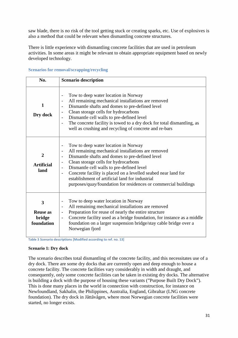
Table 3 Scenario descriptions [Modified according to ref. no. 13]
Scenario 1: Dry dock
The scenario describes total dismantling of the concrete facility, and this necessitates use of a dry dock. There are some dry docks that are currently open and deep enough to house a concrete facility. The concrete facilities vary considerably in width and draught, and consequently, only some concrete facilities can be taken in existing dry docks. The alternative is building a dock with the purpose of housing these variants (”Purpose Built Dry Dock”). This is done many places in the world in connection with construction, for instance on Newfoundland, Sakhalin, the Philippines, Australia, England, Gibraltar (LNG concrete foundation). The dry dock in Jåttåvågen, where most Norwegian concrete facilities were started, no longer exists.
32
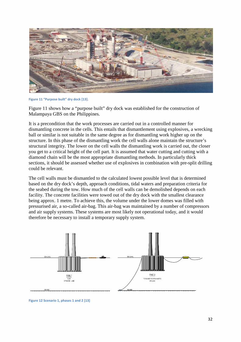
Figure 11 “Purpose built” dry dock [13].
Figure 11 shows how a “purpose built” dry dock was established for the construction of Malampaya GBS on the Philippines.
It is a precondition that the work processes are carried out in a controlled manner for dismantling concrete in the cells. This entails that dismantlement using explosives, a wrecking ball or similar is not suitable in the same degree as for dismantling work higher up on the structure. In this phase of the dismantling work the cell walls alone maintain the structure’s structural integrity. The lower on the cell walls the dismantling work is carried out, the closer you get to a critical height of the cell part. It is assumed that water cutting and cutting with a diamond chain will be the most appropriate dismantling methods. In particularly thick sections, it should be assessed whether use of explosives in combination with pre-split drilling could be relevant.
The cell walls must be dismantled to the calculated lowest possible level that is determined based on the dry dock’s depth, approach conditions, tidal waters and preparation criteria for the seabed during the tow. How much of the cell walls can be demolished depends on each facility. The concrete facilities were towed out of the dry dock with the smallest clearance being approx. 1 metre. To achieve this, the volume under the lower domes was filled with pressurised air, a so-called air-bag. This air-bag was maintained by a number of compressors and air supply systems. These systems are most likely not operational today, and it would therefore be necessary to install a temporary supply system.
Figure 12 Scenario 1, phases 1 and 2 [13]

33
Figure 13 Scenario 1, phases 3 and 4 [13]
Figure 14 Scenario 1, phases 5, 6, 7 and 8 [13]
Scenario 2: Artificial land
The scenario describes reuse of all or parts of the cell section. This can be achieved by establishing artificial land with parts of concrete facilities as a foundation. The idea is to dismantle the facility down to a suitable level for the location. If the relevant location has a depth following seabed preparation equalling about 60 metres, the entire cell section can be used. Consequently, only the shafts need to be dismantled. If the depth at the relevant location is less than 60 metres, parts of the cell wall must be dismantled.

34
It must be considered whether there is a need to remove oil pollution from the cells if the entire cell will be reused. In this case, the cells will be exposed to external overpressure, and there is consequently minimal risk of oil remnants leaking.
The cell walls are dismantled to a pre-defined level depending on the depth conditions where the new land will be established and the height above water that is needed.
After the cell walls have been dismantled to the final level, the facility can be prepared for tow to the location for establishment of artificial land. The seabed must be filled with rock of the correct fractions and that can support a concrete facility.
To establish underwater foundations it is assumed that rock fractions will be dumped here, for instance in fractions as small as 120-150 mm. Dumping of such rocks is carried out by utilising rock dumping ships, in line with those used to establish foundations for seabed pipelines for oil and gas. Such ships can establish backfills on the seabed with considerable accuracy.
After the concrete facility has been placed on the seabed, there might be a need to fill the room under the lower domes for transferring pressure to the seabed. This is achieved through injecting cement-based mortar (grout). The injection need will depend on local seabed conditions and geo-technical conditions.
Figure 15 Scenario 2, phases 3 and 4 [13]
35
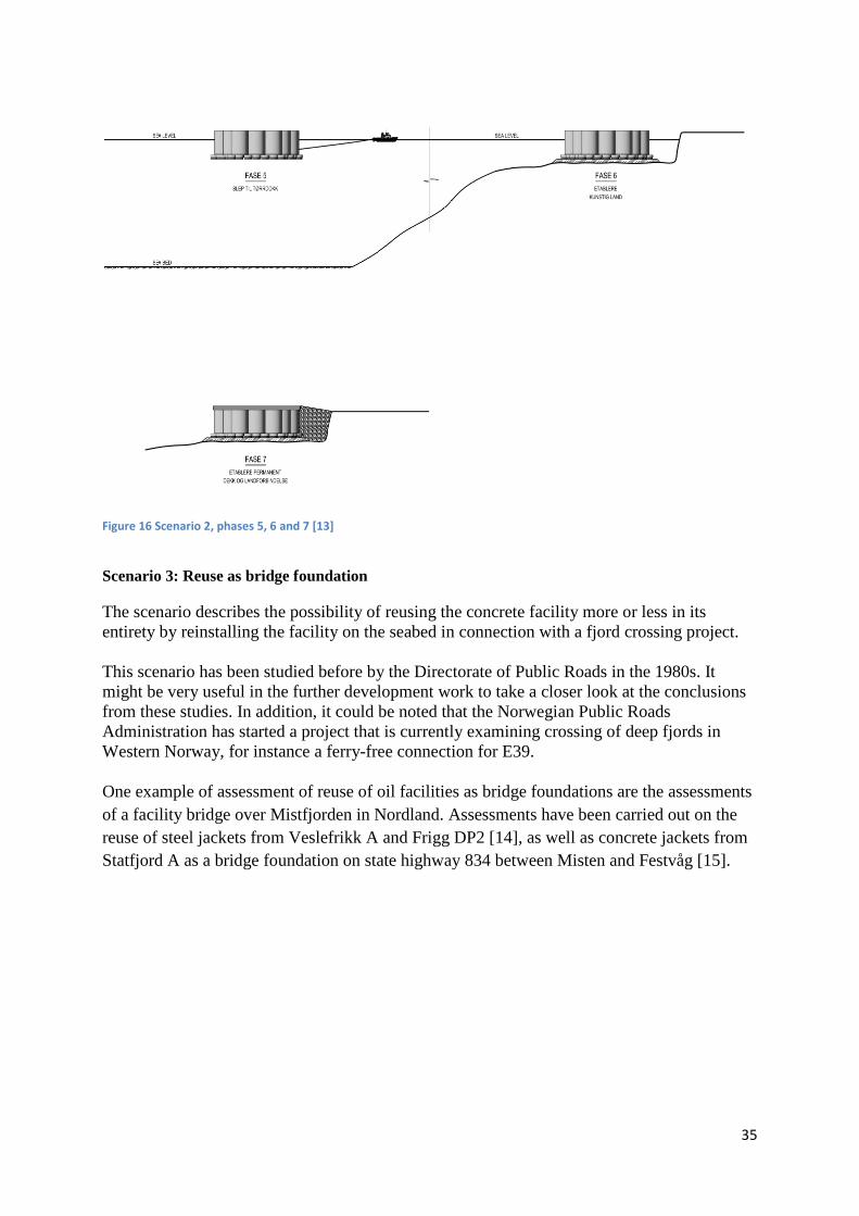
Figure 16 Scenario 2, phases 5, 6 and 7 [13]
Scenario 3: Reuse as bridge foundation
The scenario describes the possibility of reusing the concrete facility more or less in its entirety by reinstalling the facility on the seabed in connection with a fjord crossing project. This scenario has been studied before by the Directorate of Public Roads in the 1980s. It might be very useful in the further development work to take a closer look at the conclusions from these studies. In addition, it could be noted that the Norwegian Public Roads Administration has started a project that is currently examining crossing of deep fjords in Western Norway, for instance a ferry-free connection for E39. One example of assessment of reuse of oil facilities as bridge foundations are the assessments of a facility bridge over Mistfjorden in Nordland. Assessments have been carried out on the reuse of steel jackets from Veslefrikk A and Frigg DP2 [14], as well as concrete jackets from Statfjord A as a bridge foundation on state highway 834 between Misten and Festvåg [15].

36
Figure 17 Scenario 3, phases 1 and 2 [13].
Figure 18 Scenario 3, phase 3 [13].
Environmental matters Before a decision is made regarding final disposal of a concrete facility, clarity must be sought as to whether it contains substances hazardous to health and the environment which would potentially restrict the opportunities for reuse and material recycling. Environmental remediation should also be carried out to the extent possible, before potential refloating and landing. However, several reports have pointed out that it is unrealistic to remove all substances hazardous to health and the environment. Scale and precipitate with high wax content may e.g. be attached to concrete and other surfaces and be difficult to remove. The actual concrete from a disused concrete facility, particularly the surface of internal walls in tanks and cells, may also be polluted with substances hazardous to health and the environment, for example heavy metals, oil, PAH, PCB and other organic pollutants. The scope of potential pollution must be charted and assessed in each individual case.

37
The Pollution Regulations stipulate norm values for the most common inorganic and organicpollutants. If concentrations exceeding the norm value are proven in the concrete, a risk assessment must be carried out as regards disposal of the polluted concrete. This entails that if e.g. paint, plaster or sealing compounds on the concrete contain PCB exceeding the norm value, the concrete cannot be used as filler without removing PCB-contaminated paint, plaster and sealing compounds from the concrete [16]. Experience has shown that concrete which is polluted with oil may have significant variations in oil concentration inside the concrete, which is closely related to the oil type that is present, how long it has been in contact with the concrete and the concrete strength. The experience from risk assessments associated with polluted concrete aggregate is that if the concrete is under solid covers or is covered with clean fill, the potential exposure will be minimal. This is primarily due to the fact that oil becomes bound to the concrete. If the concrete aggregate is extensively polluted, i.e. concentrations exceeding the limit for hazardous waste, it must be delivered to an approved receiving facility for hazardous waste, see Chapter 9 of the Waste Regulations regarding waste disposal and Chapter 11 regarding hazardous waste. Emissions to air In the event of landing concrete facilities for scrapping and material recycling, the operation of vessels, vehicles, machines and other equipment needed to carry out the various work operations, will result in substantial emissions to air, primarily of CO2, SO2 and NOx. In connection with decommissioning of the Frigg field, the emissions of these pollution components resulting from refloating TCP2 and transporting it to shore for scrapping and material recycling were estimated. The results are shown in Table 4.
Operation CO2 tonnes NOx tonnes SO2 tonnes Marine operations Mobilisation and demobilisation 5 000 90 19
Refloating, i.e. removal from seabed 14 000 270 54
Transport to the receiving facility or to quay 13 000 240 48
Landing operations 5 000 110 21
Dismantling 1 000 113 0.3
Re-bar recycling 16 000 26 63
Total emissions to air 55 000 750 205
Table 4 Summary of emissions to air in connection with potential onshore disposal of TCP2 on the Frigg field (the facility was abandoned at the field). Emissions from removal of the top deck are not included in the figures [16].
In general, scrapping of concrete facilities will entail operations which lead to substantial emissions of dust, including chiselling, crushing, cutting and possibly blasting the concrete and subsequent handling of the crushed concrete masses. In addition, dust may escape the actual facility area, particularly in the event of dry weather and wind. It is assumed that it will be possible, to a certain degree, to limit emissions and spread of dust through various measures such as covering dusty operations, use of water spreaders and frequent sweeping of outdoor areas with a solid covering. However, without specific experience as a reference, it is difficult to predict the volume of residual emissions to expect.

38
If dust from the dismantling activities spreads to the surroundings to a significant degree, measurements of particulate matter and fallout dust must be carried out to assess whether applicable requirements and guidelines are fulfilled. The requirements for maximum permissible concentrations of particulate matter are stipulated in Section 7 of the Pollution Regulations. The daily mean concentration of particulate matter (PM10) must not exceed 50 µg/m3, while the annual mean value must not exceed 40 µg/m3. General limits have not been stipulated for fallout dust which apply directly for receiving facilities for disused offshore facilities. NILU (the Norwegian Institute for Air Research), however, operates with the following assessment criteria for fallout dust:
Very high >13 g/m2 per 30 days High 8-13 g/m2 per 30 days Moderate 3-8 g/m2 per 30 days Low <3 g/m2 per 30 days
Section 30-5 of the Pollution Regulations generally stipulates the following requirements for enterprises which produce aggregate, gravel, sand and shingle: Emissions of stone dust/dust/particles from the enterprise’s overall activities must not result in the volume of fallout dust exceeding 5 g/m2 over 30 days. This applies to the mineral percentage measured at the nearest neighbour, or another neighbour who is potentially more exposed, cf. Section 30-9. If binding requirements are to be stipulated for dust fallout in the receiving facilities' permits pursuant to the Pollution Control Act, it will be natural to use NILU's guidelines and the requirements in Section 30 of the Pollution Regulations as a basis. If fouling remains on modules/elements/blocks lifted onshore, this may result in odour issues around the receiving facility. Such fouling should therefore be removed as quickly as possible. Interim storage and/or further handling of fouling onshore may also cause odour issues. Use of nitrate-based products to prevent sulphide formation in the event of bacterial decomposition of the fouling, may reduce these issues. Discharges to water Pollution of the external environment with discharges to water may e.g. occur from the following sources at a receiving facility:
- discharge point for outlet pipes - oil separators with drainage basins/sand traps - cleaning activities - storage tanks on the concrete facility - tank systems at the receiving facility - discharges from vessels involved in landing operations - storage site for hazardous waste - run-off from the area

39
Pollution parameters which may occur in water from a typical receiving facility include the following:
- hydrocarbons - heavy metals, e.g. arsenic, lead, cadmium, copper, chromium, mercury, nickel and
zinc - polycyclic aromatic hydrocarbons (PAH) - polychlorinated biphenyls (PCB) - brominated flame retardants (BFR) - low-level radioactive compounds - total organic carbon (TOC) - nutrients
Run-off from the activities can be controlled by, among other things, having solid decks and collection systems directing the water to a treatment facility and oil filters. To keep the discharges as low as possible and to avoid overloading the treatment facilities, it will also be important to frequently sweep surfaces with solid coverings. The EU Water Framework Directive (the Water Directive) stipulates an overall framework for managing water resources. The Directive has been implemented in Norway through the Water Regulations. The key requirements are that a good ecological condition must be achieved in the water resources and that measures must not be implemented which lead to significant deterioration of the condition. Management plans must be prepared on a regional level to be used as a basis for the county municipalities' activities, and which will be normative for municipal and national planning and activities in the water regions. Noise Chiselling, crushing, cutting and potentially blasting of concrete facilities will generate noise. In addition, there will be noise from operating cranes and diesel engines, as well as from traffic and cleaning activities. It may be challenging to identify good measures to limit noise issues associated with scrapping concrete facilities near/on land. Relevant measures at the sources may be, if possible, to choose low noise equipment and different ways of shielding noisy activities. Improved noise insulation of buildings and construction of noise deflection walls may be considered for exposed neighbouring properties. The Ministry of the Environment's planning guidelines for noise (T-1442) [17] stipulate recommended noise requirements for e.g. industrial activities forming the basis for municipal area development plans. Binding noise requirements are also stipulated in the receiving facilities' permits pursuant to the Pollution Control Act. It must be assumed that a majority of the noise will be periodic and will thus be perceived as more bothersome than noise of more constant nature. T-1442 recommends that periodic noise be regulated more stringently than other noise. In general regarding waste disposal Based on environmental and resource considerations, waste must be handled in the following prioritised order: reuse, material recycling, energy recycling and disposal.

40
Reuse means that a product is reused in its original form, and normally does not require a permit. For the product to be reused, it cannot contain substances hazardous to health or the environment or materials that are currently prohibited, for example mercury, PCB or asbestos. Material recycling: For a material to be designated as recycled, all of the following requirements must be satisfied:
- The material must, in its new form, have a function beyond its volume, for example insulating properties.
- The material's properties must be specified in advance. - The material must be of value for someone. The disposal must take place because the
recipient has use for it, and not because the supplier wants to get rid of it. - The material must not be polluted with other waste or environmentally damaging
components. Recycled material may be used without a special permit from the pollution authorities if the material and its use conform to the criteria mentioned above. Clean, crushed concrete can therefore be used in instances where one would otherwise use equivalent amounts of aggregate or other backfill. Energy recycling entails incinerating waste. By incinerating the waste in modern energy recycling plants, the waste issue is converted to an important energy resource. Disposal is basically only an alternative if the material cannot be reused or recycled in accordance with the above criteria. Energy recycling and onshore disposal are not considered to be relevant disposal solutions for the main components of the concrete facilities on (concrete and re-bars). Reuse of concrete elements and recycling concrete and re-bars may be relevant solutions and will be discussed in more detail below. Reuse and recycling of concrete This subchapter is, in its entirety, based on the report from Multiconsult [16] and its references. The publication from the Norwegian Concrete Association [18] deals with use of recycled concrete aggregate. In Finland, most demolished concrete is reused as backfill material. It is pointed out that crushed concrete is ideal as backfill material, as the crushed concrete contains unreacted cement and will therefore become harder after use, and will thus have a greater/improved load capacity. In the US, the Recycled Materials Company Inc. has specialised in recycling concrete and asphalt. The products they can deliver are bases for roads, coarse fractions, drainage layers in ditches, structural backfill, landscaping stone, pebbles for wheel tracks, coverage materials, bases under foundations, drainage mass, washed aggregate and gravel for trails/courtyards. The volumes of concrete that may be generated from disused concrete facilities, will vary between 120 000 – 550 000 tonnes per facility; which is around the same magnitude as Norway's total rock extraction per year. In total, this entails that the Condeep facilities on the Norwegian shelf have approx. 4.5 million tonnes of concrete and re-bars. According to a

41
report from the Norwegian Petroleum Directorate [19], there are many relevant applications and market areas for the various products:
- The fine fraction will, depending on the size of the aggregate and the quality, be used as aggregate material in new concrete and asphalt, as a base for road building or as backfill material in various types of backfilling.
- Coarser fractions of crushed concrete may be used in backfills, depending on the size of the aggregate and its quality.
- Larger reinforced pieces of concrete may for example be used as erosion protection. - Modules/rings may e.g. be used within the fish farming industry (concrete tanks) or as
foundations for wind turbines. Larger elements could also potentially be used as bridge piers, foundations for new quay areas, etc. [13, 14, 15]. The benefits of reuse and recycling of concrete will first and foremost be associated with reduced consumption of non-renewable resources (gravel, sand etc.) and minor disruptions to the landscape in connection with this. For certain purposes, recycled concrete will most likely also have properties which make it more suitable than other materials. The fact that concrete strength increases with age due to the content of unreacted cement for example, will be favourable for some applications. However, many challenges are associated with reuse and recycling of concrete. The large volumes in question make it potentially challenging to sell the concrete within a reasonable time after scrapping. Interim storage and final disposal of concrete elements/blocks for which applications cannot be found, may be a challenge, both as regards costs and area occupation. Reuse of larger concrete elements presumes that they can be transported to the relevant usage sites without substantially deteriorating the properties of the reinforced concrete. Questions regarding product responsibility, both as regards safety and durability, may reduce the market for the pieces of concrete. In the event of use of concrete blocks as coastal protection blocks, the risk of re-bar corrosion must be considered. A different perspective will be associated with aesthetics in the use of concrete blocks for this purpose. Recycling of re-bars A report from Dames & Moore from 1997 [20] points out that there are many challenges associated with separating re-bars (reinforcement bars) in connection with crushing concrete. On the other hand, the amount of re-bar which may be recycled is considerable and must be viewed in connection with the alternative, which is to extract iron ore with associated industrial processes to produce re-bar. One example is the concrete facility Gullfaks A, which has approx. 130 000 m3 of concrete with approx. 270 kg of re-bars per m3 of concrete. This means a total of 312 000 tonnes of concrete and approx. 35 000 tonnes of re-bars. Re-bars that can be recycled can therefore, as opposed to most other waste fractions, be a good source of income.
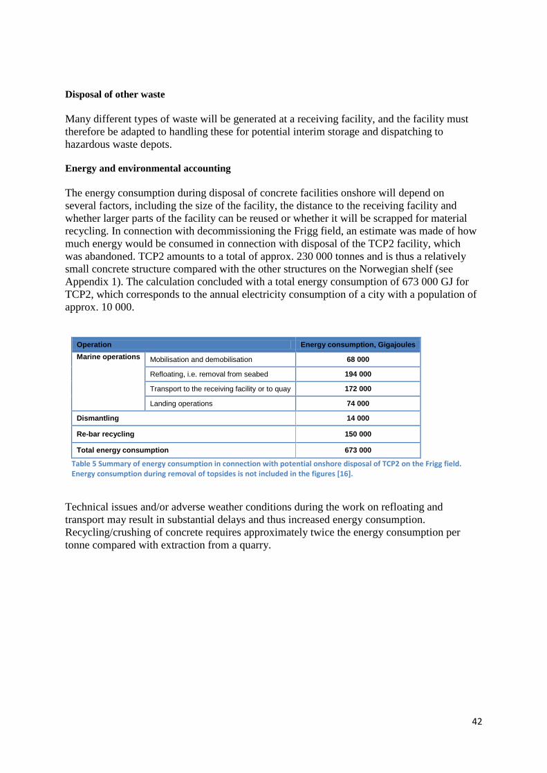
42
Disposal of other waste Many different types of waste will be generated at a receiving facility, and the facility must therefore be adapted to handling these for potential interim storage and dispatching to hazardous waste depots. Energy and environmental accounting The energy consumption during disposal of concrete facilities onshore will depend on several factors, including the size of the facility, the distance to the receiving facility and whether larger parts of the facility can be reused or whether it will be scrapped for material recycling. In connection with decommissioning the Frigg field, an estimate was made of how much energy would be consumed in connection with disposal of the TCP2 facility, which was abandoned. TCP2 amounts to a total of approx. 230 000 tonnes and is thus a relatively small concrete structure compared with the other structures on the Norwegian shelf (see Appendix 1). The calculation concluded with a total energy consumption of 673 000 GJ for TCP2, which corresponds to the annual electricity consumption of a city with a population of approx. 10 000.
Operation Energy consumption, Gigajoules Marine operations Mobilisation and demobilisation 68 000
Refloating, i.e. removal from seabed 194 000
Transport to the receiving facility or to quay 172 000
Landing operations 74 000
Dismantling 14 000
Re-bar recycling 150 000
Total energy consumption 673 000
Table 5 Summary of energy consumption in connection with potential onshore disposal of TCP2 on the Frigg field. Energy consumption during removal of topsides is not included in the figures [16].
Technical issues and/or adverse weather conditions during the work on refloating and transport may result in substantial delays and thus increased energy consumption. Recycling/crushing of concrete requires approximately twice the energy consumption per tonne compared with extraction from a quarry.

43
6. Abandoning concrete facilities offshore Abandonment on the field will be a cost-efficient alternative which may also have advantages as regards safety and the environment. So far, two concrete facilities have been abandoned on the Norwegian shelf.
Technical feasibility There will be far fewer technical challenges by leaving the actual concrete structures than through other disposal solutions. However, deconstruction of the superstructure will be more challenging offshore than onshore. In addition, there will be challenges and technology qualification if the shafts are to be cut. The shafts may extend above the sea surface if they are suitably marked with lights and navigation equipment. It may be challenging to remove potential pollution in the cells, but not all concrete substructures have oil storage. Offshore disposal options The options include abandonment with the shafts intact and permanent marking and cutting of the shafts for abandonment on the seabed or cutting the shafts down to 55 m below the sea surface and potentially transporting the shafts onshore. However, it is uncertain whether qualified technology exists to do this in a controlled manner. Safety Shipping considerations Based on the Norwegian Maritime Directorate's database [21] of shipping accidents, there does not appear to be an overabundance of episodes near petroleum facilities. The registered episodes are associated with vessels with direct connections to the petroleum field. But intensive monitoring of the waters surrounding the facilities is deemed to have reduced the number of incidents, and this monitoring is expected to be reduced in connection with shutdown of the facility [22]. We must consider that there is a risk of collision between vessels and all abandoned concrete structures. The Ministry of Petroleum and Energy has assessed the risk of collision between vessels and an abandoned concrete facility as minor, compared with the risk associated with removal, presuming that navigational aids (e.g. lights and electronic marking) are installed on the facility [23]. The Ministry also requires the position to be updated in electronic charts and navigation databases. The Petroleum Safety Authority Norway's risk assessment [24] shows the number of vessels on a collision course with facilities over time. In Figure 19 , the number has been updated to also cover 2011. The reduction in the number of incidents is attributed to improved monitoring. There have been two collisions between passing vessels and facilities on the Norwegian shelf since 1980. Neither of the collisions have resulted in significant damage to the vessel or the facilities. If we assume a period of 32 years and an average of 50 facilities during this period, the annual observed collision frequency will be P = 2 /(32*50) = 1*10-3. If we presume that, through improved monitoring and better systems on the vessels, we have improved safety by a factor of up to ten, in relation to the average for this period, the annual

44
probability of collision per facility will be between 1*10-3 and 1*10-4. With 12 abandoned facilities there will be one collision approximately once between every one hundred years and one thousand years. Marking of the abandoned facilities will also be important. The probability of substantial damage to a vessel in the event of a collision will be lower.
Figure 19 Number of incidents with vessels on collision course in relation to the number of facilities monitored from Sandsli TTS [24, updated by the PSA].
Fishery considerations During operations, the petroleum facilities amount to a physical obstacle for the fisheries, due to safety zones and traffic restrictions. Abandonment will also result in areas becoming inaccessible for fishing, but the occupied areas will be smaller than during operations. If we disregard the size, abandonment of concrete facilities will not manifest differently than for other objects (e.g. stones and shipwrecks) on the seabed that must be avoided. Multiconsult [16], via the Directorate of Fisheries, has collected position data from Norwegian fishing vessels for 2009 as shown in Figure 20. Under the assumption that all other foreign objects on the seabed are removed, trawling can take place close to abandoned concrete facilities. In theory, lost area will only be represented by the external border around all the shafts and tanks near the seabed, and all sides of this outer edge can be passed by a trawl. Abandonment of concrete facilities is therefore presumed to only affect trawling in the surroundings to a minor degree [16]. Abandonment of the concrete facility is deemed to have a minor negative impact on seining in the North Sea. The target species in this fishery move freely, and fishing takes place where the species are available at any given time in catchable amounts.

45
Figure 20 Overview of Norwegian trawlers actively fishing in the North Sea in 2009. One pixel in the shaded area represents 6x6 km [16]
Environmental matters Any artificial structure, including a concrete facility, which protrudes above the seabed, will function as an artificial reef. This applies both while the facility is operational, as well as in the event of potential abandonment of all or parts of the facility. Fouling on the structures depends on the structure's surface, lighting and current conditions and the depth at which the structure is located. A concrete facility located at depths exceeding 300 metres on the Norwegian shelf forms a habitat for both species normally found in the beach zone, as well as species normally only found at greater depths. Studies on the production of biomass on steel facilities show that this is much higher than the production in coastal kelp forests, which is one of the most productive "nature types" in Norway. There are no corresponding studies for concrete facilities, but there is no doubt that concrete facilities have also provided new habitats in the North Sea.

46
In the event of potential removal of the concrete facility, the established fauna on the structures will be lost, and over time the natural condition will return to how it was before the facility was installed. In relation to the current situation, this entails both reduced biodiversity and a reduced volume of biomass. Research shows that abandonment of concrete facilities will not have an impact on fish at the population level, but due to the increased biomass and biodiversity, the concrete facilities may function as an area with greater density compared with areas further away from the facilities [16]. One potential long-term environmental issue may be possible leakage of polluting substances from the actual concrete and from the storage cells near the seabed. However, it is assumed that, if the legs eventually disintegrate and breaks, the storage cells will remain as large "sediment traps" on the seabed, and natural particles in the water may cover any polluting sediments in the cells.

47
7. Overall environmental assessments of various disposal solutions Appendix 2 presents a table that provides a comprehensive overview of environmental consequences and other benefits and disadvantages inherent in the different alternatives for final disposal of disused concrete facilities. The potential environmental consequences associated with transporting the facilities to shore may be substantial. There is a risk of accidents in connection with the operation of ”refloating” the facilities and transporting them to shore, but the conflicts are first and foremost associated with environmentally prudent cleaning, dismantling and interim waste storage. The operations result in a risk of spreading polluted water, and they will generate substantial amounts of dust and noise. Available areas will be required both onshore and offshore, and the potential conflict level with neighbours is presumed to be substantial. The refloating operations and transport will also result in significant emissions of greenhouse gases. The environmental consequences of abandoning concrete facilities on the shelf are preseumed to be relatively modest. There will be discharges to sea in connection with cleaning and preparing for offshore abandonment. The biological production currently taking place on the facilities, will be lost if they are removed. Abandonment will have minor impact on fish populations, but may be in conflict with fishery interests due to area occupation. Energy consumption and emissions to air will be far lower by abandoning the concrete facilities offshore than by disposing of them onshore. Overall, the available information indicates that offshore abandonment will have the least environmental consequences.

48
8. Presumed disposal costs The Norwegian Petroleum Directorate annually receives reporting per field where the costs are distributed among cessation costs and disposal costs. The authorities' insight in detailed dispoal estimates is limited. Such costs are included as part of the cessation plans for specific fields, which must be submitted two to five years before cessation. Cessation costs are the costs incurred leading up to when the facilities are prepared for final disposal, i.e. plugging wells, cleaning and preparing for disposal. Disposal costs are costs associated with removal, transport and potential abandonment. There is currently no reporting per facility or parts thereof. An overview is shown below of the development in disposal costs reported on the fields with concrete substructures resting on the seabed. It is important to be aware that the costs include deck facilities and other facilities associated with the same field. One example is the Oseberg field, which in addition to the Oseberg A concrete facility, also has three facilities with steel jackets and multiple subsea facilities. In their data collection, the operators must report unbiased estimates. Since there is uncertainty associated with whether the concrete substructures will be removed, several fields have reported weighted cost estimates, where a assumed probability of removal of the substructure is multiplied by the estimated cost of disposal.
Figure 21 Development in total disposal costs for operational concrete facilities resting on the seabed. Source: NPD
Figure 21 above shows that the reporting was most likely deficient before the autumn of 2002. The reported costs have increased substantially in recent years. This is partly associated with the fact that the estimates have improved as the industry has acquired empirical figures from completed disposals. Another cause is the general cost increase associated with all activity on the shelf. One substantial challenge is that there is no relevant basis for comparison for estimating costs associated with refloating, transport and recycling of this type of concrete facilities. It is most likely possible to estimate a cost, but the uncertainty will be significant. The overruns familiar
0
10 000
20 000
30 000
40 000
50 000
2001 2002 2003 2004 2005 2006 2007 2008 2009 2010 2011
Mill
ione
r 201
2 N
OK
Rapporteringsår

49
from field development can serve as an illustration of this uncertainty. Here you start from scratch and build something where you yourself determine the execution with known materials and methods. Yet we still see many examples of relatively large overruns associated with developments. As regards disposal, there are many uncertainties associated with what will actually be removed, the condition it is in and how this will be carried out. We are in the process of acquiring a certain amount of experience with smaller steel facilities, which may assist in the estimation. But as regards concrete substructures, we have few, if any, relevant references. Potential financial benefits associated with removal of concrete substructures One obvious savings is associated with disposal of the deck facilities. If as much of the deck as possible can accompany the concrete substructure to shore, there will be significant savings on the offshore activity associated with scrapping. Instead of operating with disassembly of heavy modules or dividing into smaller units before transporting onshore, this activity can be carried out in smoother waters with less costly labour and equipment. It is unclear how much of the deck facilities can potentially be transported to shore in this manner, and this will vary from facility to facility, depending on buoyancy and balance point. Other potential savings are associated with cleaning the facilities. However, it is not equally obvious that it is possible to wait until the substructure is on land before this is done, since the deballasting process entails pumping significant volumes out of cells and shafts.

50
9. References
1. OGP, 2003, Disposal of disused offshore concrete gravity platforms in the OSPAR Maritime Area, report no. 338
2. Statoil, 2011, Decommissioning and disposal of Statfjord A - proposed impact assessment programme
3. Norwegian Contractors, 1992, Refloating a concrete platform – possibilities and limitations - Offshore Northern Seas 28 August 1992, Trond Føsker
4. Dr.techn. Olav Olsen a.s, 2010, Disposal of concrete facilities
5. OSPAR Decision 98/3 on the Disposal of Disused Offshore Installations: http://www.ospar.org/documents/dbase/decrecs/decisions/od98-03e.doc
6. United Nations convention on the law of the sea:
7. IMO Guidelines in Resolution A.672:
http://www.un.org/Depts/pilot/convention_agreements/texts/unclos/closindx.htm
8. OSPAR Recommendation 2006/5 on a Management Regime for Offshore Cuttings Piles:
http://www.fao.org/DOCREP/003/W3591E/w3591e04.htm#bm4.5.2
http://www.ospar.org/documents/dbase/decrecs/recommendations/06-05e_Rec%20drill%20cuttings%20regime.doc
9. Section 17 of the Management Regulations relating to risk assessments and emergency preparedness analyses
10. Section 44 of the Management Regulations, Section 96 of the Activities Regulations and Section 82, third subsection of the Facilities Regulations with guidelines
11. Comments on the interpretation basis for the Regulations relating to load-bearing structures and guidelines for loads and load effects, status as of 21 January 1989, NPD report OD-89-14
12. DNV, 2008, OLF drill cuttings, data collection, 2008-4132/DNV
13. AF Decom Offshore AS, 2011, Study on technical challenges associated with transport, receipt and disposal of concrete facilities onshore
14. Centre for Innovation and Economics report 3/2010 from Bodø Graduate School of Business, 2010, Platform bridge over Mistfjorden – Environmental aspects and legal issues, cf. [13] AF Decom Offshore AS
15. Aas-Jakobsen for the Norwegian Public Roads Administration, Region North, 2008, Rv. 834 Platform bridge over Mistfjorden – R&D report, report no. 10282-01, cf. [13] AF Decom Offshore AS
16. Multiconsult AS, 2011, Study of environmental consequences from disposal of concrete facilities
51
17. The Ministry of the Environment's guidelines for handling noise in area planning (T-1442)
18. Norwegian Concrete Association, 1999, Material recycling of concrete and masonry for concrete production, publication no. 26
19. Dr.techn. Olav Olsen a.s, 1996, Disposal of concrete facilities – Recycling and reuse
20. Dames & Moore, Reverse Engineering Ltd. 1997. Re-cycling of concrete, Environmental Account. Dismantling and Recycling of Concrete Platforms. Prepared for Aker NC, 10 Feb. 1997, p. 53, cf. [16] Multiconsult AS
21. The Norwegian Maritime Directorate's data selection:
22. The Norwegian Maritime Directorate, 2010, The Norwegian Maritime Directorate's registered shipping accidents during the period from 1981 to 2009.
http://www.sjofartsdir.no/ulykker-sikkerhet/ulykkesstatistikk/datauttrekk/
http://www.sjofartsdir.no/no/sikkerhet/statistikk/Datauttrekk/ cf. [16] Multiconsult AS
23. Storting Proposition No. 38 (2003-2004) and Storting Proposition No. 9 (2008-2009), cf. [16] Multiconsult AS
24. The Petroleum Safety Authority Norway. Risk level in the petroleum activities. Main report, development trends 2010, Norwegian shelf http://www.ptil.no/getfile.php/PDF/RNNP%202010/RNNP_hovedrapport_sokkel_2010_rev1b[1].pdf

52
Appendix 1 General description of the concrete facilities on the Norwegian shelf
Operational facilities
Facility Oseberg A
Type Condeep, 4 shafts Located Northern part of the North
Sea The facility's function
Production/Accommodation
Operator Statoil Water depth (m) 109 Installation year 1987 Superstructure weight (tonnes)
37 000
Foundation incl. ballast (tonnes)
320 000
Oil storage No Facility Troll A
Type Condeep, 4 shafts Located Northern part of the
North Sea. The facility's function Production/Drilling/
Accommodation Operator Statoil Water depth (m) 302 Installation year 1995 Superstructure weight (tonnes)
25 000
Foundation incl. ballast (tonnes)
661 500
Oil storage No

53
Facility Troll B
Type Semisub Located Northern part of the North
Sea. The facility's function
Production/Accommodation
Operator Statoil Water depth (m) 320 Installation year 1995 Superstructure weight (tonnes)
22 000
Foundation incl. ballast (tonnes)
139 000
Oil storage No
Facility Draugen A
Type Condeep, monotower
Located Norwegian Sea The facility's function Production/Drilling/
Accommodation Operator Shell Water depth (m) 252 Installation year 1993 Superstructure weight (tonnes)
28 000
Foundation incl. ballast (tonnes)
208 000
Oil storage (m3) 222 582
Facility Sleipner A
Type Condeep, 4 shafts Located Southern part of the
North Sea The facility's function Production/Drilling/
Accommodation Operator Statoil Water depth (m) 83 Installation year 1993 Superstructure weight (tonnes)
37 000
Foundation incl. ballast (tonnes)
788 000
Oil storage No
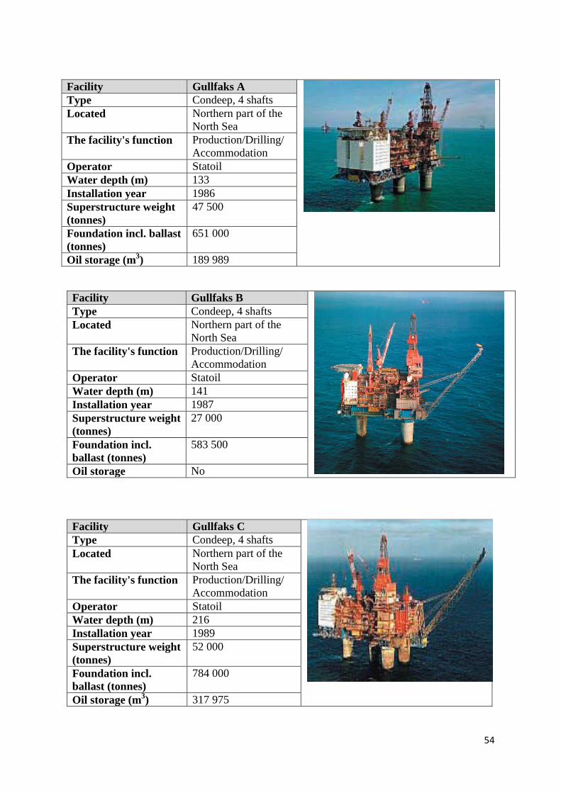
54
Facility Gullfaks A
Type Condeep, 4 shafts Located Northern part of the
North Sea The facility's function Production/Drilling/
Accommodation Operator Statoil Water depth (m) 133 Installation year 1986 Superstructure weight (tonnes)
47 500
Foundation incl. ballast (tonnes)
651 000
Oil storage (m3) 189 989
Facility Gullfaks B
Type Condeep, 4 shafts Located Northern part of the
North Sea The facility's function Production/Drilling/
Accommodation Operator Statoil Water depth (m) 141 Installation year 1987 Superstructure weight (tonnes)
27 000
Foundation incl. ballast (tonnes)
583 500
Oil storage No
Facility Gullfaks C
Type Condeep, 4 shafts Located Northern part of the
North Sea The facility's function Production/Drilling/
Accommodation Operator Statoil Water depth (m) 216 Installation year 1989 Superstructure weight (tonnes)
52 000
Foundation incl. ballast (tonnes)
784 000
Oil storage (m3) 317 975

55
Facility Statfjord A
Type Condeep, 3 shafts Located Northern part of
the North Sea The facility's function Production/Drilling
/Accommodation Operator Statoil Water depth (m) 145 Installation year 1977 Superstructure weight (tonnes)
41 300
Foundation incl. ballast (tonnes)
254 000
Oil storage (m3) 190 785
Facility Statfjord B
Type Condeep, 4 shafts Located Northern part of
the North Sea The facility's function Production/Drilling
/Accommodation Operator Statoil Water depth (m) 145 Installation year 1981 Superstructure weight (tonnes)
42 200
Foundation incl. ballast (tonnes)
434 000
Oil storage (m3) 302 075
Facility Statfjord C
Type Condeep, 4 shafts Located Northern part of
the North Sea The facility's function Production/Drilling
/ Accommodation
Operator Statoil Water depth (m) 145 Installation year 1984 Superstructure weight (tonnes)
48 100
Foundation incl. ballast (tonnes)
358 000
Oil storage (m3) 302 075

56
Facility Heidrun A
Type Floating tension leg in concrete
Located Northern part of the North Sea
The facility's function Production/Drilling/Accommodation
Operator Statoil Water depth (m) 345 Installation year 1995 Superstructure weight (tonnes)
65 000
Foundation incl. ballast (tonnes)
290 000
Oil storage (m3) No

57
Abandoned facilities
Facility Ekofisk T with
barrier
Type Doris Located Southern part of the
North Sea Facility's original function
Storage tank and protective barriers
Operator ConocoPhillips Water depth (m) 77 + subsidence Installation year 1973 + 1989 (barrier) Superstructure weight (tonnes)
33 400
Foundation incl. ballast (tonnes)
273 700 896 900
Oil storage (m3) 158 987 Facility Frigg TCP2
Type Condeep, 3 shafts Located Northern part of the
North Sea Facility's original function
Production
Operator Total Water depth (m) 102 Installation year 1977 Superstructure weight (tonnes)
22 900
Foundation incl. ballast (tonnes)
229 200
Oil storage No

58
Appendix 2 Overview of potential environmental consequences of abandoning concrete facilities offshore, or disposing of the facilities onshore
Activity Potential sources of pollution
Environmental consequences Concern Positive
elements
Offshore abandonment
Entire concrete facility
Potential leakage of pollution to water column and sediments, which may affect habitats over the long term.
Structure's physical presence on the seabed.
Less energy consumption
and emissions to air than for
refloating, transport and
scrapping
No disturbance of biological
diversity on and around the
concrete facility
Not possible to recycle steel or concrete from the installation. Actual amounts and concentrations of environmental toxins in the structure. Potential risk associated with navigation and commercial fishing.
Refloating
Energy consumption and emissions to air from vessel, equipment and cranes. Loss of equipment/ballast, etc.
Pollution from discharges to water and emissions to air.
Leakage of pollution to the water column and sediments, which may affect habitats for marine flora and fauna.
The original natural
condition will be re-established
over time. Direct impact on marine life and indirect impact associated with disturbing polluted sediments.
Reduced biological diversity.
Transport
Energy consumption and emissions to air.
Local reduction in air and water quality
Accident/damage to the installation in connection with transport.
None Accident/damage to vessel or the installation.
Discharge of pollutants to sea.
Obstructions/remnants on the seabed. Loss of the installation.
Landing
Energy consumption and emissions to air
Local reduction in air and water quality.
Access restrictions.
None
Use of explosives and/or mechanical cutting.
Disturbing the local environment in the form of noise and dust.
Leakage of pollution to the water column and sediments, which may affect habitats for flora and fauna with associated food chains.
Sediment disturbances during refloating and placement on the seabed outside receiving facility/quay.
Mobilisation of sediments with associated increased turbidity in the water column.
Remnants on the seabed following landing activities.
Scrapping and disposal onshore
Physical
Visual impact, disturbance in the local environment as regards noise and dust.
General disturbance of the local environment. Physical presence and significant area occupation.
Access to
concrete and reinforcement bars which can be reused or
material recycled
Energy consumption and emissions to air, through use of cranes, crushing works and vehicles, etc.
Substantial emissions to air in order to crush concrete in relation to extraction in conventional quarries.
Local/regional reduction in air quality.
Removal and treatment of marine fouling.
Odour. Discharge of excess water with particles. Noise
Polluted paint/concrete containing hazardous substances in fouling.

59
Dismantling processes
Leakage of unwanted pollution (heavy metals/oil) to surface, ground, and seawater which may affect food chains.
Fine particles and dust may contain nitrogen. Run-off results in multiple suspended particles in the water and causes problems for fish/other organisms.
Emissions to air, dust formation. Noise from the facility. Eutrophication and increased sedimentation from dust particles.
Working environment and health impact on employees and the local environment.
All waste delivered for recycling/interim storage, i.e. run-off from areas, etc., on the facility.
Leakage of polluting masses (concrete aggregate), which may affect water/groundwater.
Large volumes of concrete aggregate which cannot be reused or used as backfill.
Transporting waste at the site and to approved recieving facilities.
Risk of incidents/accidents during transport of substances that are hazardous to health and the environment internally or to an approved recieving facility.
Leaks from vehicles or vessels carrying hazardous waste/pollution in connection with transport.
Non-certified recieving facilities, depots or landfills.
Spread of pollution ”unregulated landfills”
Source: Multiconsult AS report [16]