disposal high level waste including spent nuclear fuel
TRANSCRIPT

International Conference on the Safety of Radioactive waste Management
SESSION 3d
Disposal of
High Level Waste
Including Spent Nuclear Fuel
Declared as Waste

Session 3d– HLW IAEA-CN-242
2
ORAL PRESENTATIONS
No. ID Presenter Title of Paper Page
03d – 00 INV 03d J. Heinonen
Finland
Regulatory Experiences from the Spent Fuel
Disposal Step-Wise Implementation
4
03d – 01 111 V. Havlová
Czech Republic
Complex Safety Assessment Model of
Radioactive Waste Deep Geological Disposal in
the Czech Republic
7
03d – 02 130 A. Hagros
Finland
Preparing Posiva’s Post-Closure Safety Case
Towards the Operational Phase
11
03d – 03 145 S. Voinis
France
Andra’s Safety Options of French Underground
Facility Cigeo – a Milestone towards the
Licensing Application
15
03d – 04 172 I. Niemeyer
Germany
Bridging Nuclear Safety, Security and
Safeguards at Predisposal and Geological of
High Level Waste and Spent Nuclear Fuel
20
03d – 05 141 T. Fujiyama
Japan
Development of the NUMO Pre-selection, Site-
specific Safety Case
25
03d – 06 131 L. Bailey
United Kingdom
Development of a Generic Environmental
Safety case for the Disposal of Higher Activity
Wastes in the UK
29
03d – 07 184 D. Pellegrini
France
SITEX, the European Network of Technical
Expertise Organisation for Geological Disposal
33
03d – 08 207 A. Ström
Sweden
Research and Development Needs in a Step-
Wise Process for the Nuclear Waste Programme
in Sweden
38

Session 3c – ILW IAEA-CN-242
3
POSTER PRESENTATIONS
No. ID Presenter Title of Paper Page
03d – 09 26 F. Charlier
Germany
Germanys New Route towards a Repository for
High Level Waste – Scientific Challenges
43
03d – 10 32 J.-W. Kim
Korea
Recent Safety Assessment of a Reference
Geological Disposal System for Radioactive
Waste from Pyro-Processing in Korea
47
03d – 11 34 Y. Kovbasenko
Ukraine
Assessment of Decay Heat in Process of Spent
Nuclear Fuel Disposal
51
03d – 12 94 S. Suzuki
Japan
Assessment of Pre- and Post –Closure Safety in
the NUMO Safety Case for a Geological
Repository
56
03d – 13 96 J. Stastka
Czech Republic
Research, Development and Demonstration
Projects at the Josef Underground Laboratory
60
03d – 14 125 V. Maree
South Africa
The Management of Used (Spent) Fuel and
High Level Waste in South Africa
64
03d – 15 140 J. Leino
Finland
Regulatory Experiences in Reviewing
Construction License Application for the
Disposal of Spent Nuclear Fuel in Finland
69
03d – 16 155 L. Vondrovic
Czech Republic
Generic Underground Research Facility in the
Middle Stage of the Site Selection Process:
Bukov URF, Czech Republik
73
03d – 17 161 F. Launeau
France
Cigeo Project: from Basic Design to Detailed
Design – pursuant to Reversibility
77
03d – 18 171 B.B. Acar
Turkey
Impact of Storage Period on Safe Geological
Disposal of Spent Fuel
81

Session 3d– HLW IAEA-CN-242
4
03d – 00 / INV 03b. Disposal of High Level Waste
REGULATORY EXPERIENCES FROM THE SPENT FUEL DISPOSAL STEP-WISE
IMPLEMENTATION
J. Heinonen
Radiation and Nuclear Safety Authority (STUK), Finland
E-mail contact of main author: [email protected]
1. Introduction
Finland began planning and preparing for nuclear waste management measures in the 1970s,
during the procurement and construction phase of the first nuclear power plants. In 1983, the
Finnish Government made a policy decision on the principles and schedules of nuclear waste
management. In 2000, the Government adopted a favourable Decision-in-Principle (DiP)
accepting the concept of a deep disposal facility for spent fuel from the Finnish nuclear
power plants in Olkiluoto and Loviisa. This DiP was confirmed by the Parliament in 2001. A
construction licence application (CLA) for the encapsulation and disposal facility was
submitted to the Government in 2012. The Finnish government granted in 12th November
2015 Posiva license to construct spent nuclear fuel (SNF) encapsulation plant and disposal
facility in Olkiluoto. Government decision was supported with STUK’s safety evaluation.
Before encapsulation and disposal process begins, Government has to issue a operating
license. Operating license application is expected to be submitted in early 2020’s and disposal
is planned to start 2023.
STUK, as the independent safety regulator, has been performing stepwise review of
developing safety case and R&D needed to demonstrate safety of SNF disposal. STUK
strategy has also been that safety regulation is developed coincide with the development of
disposal. This approach has enabled to include experiences and growing knowledge timely
into safety regulation.
STUK also decided to participate actively in pre-siting and pre-license phase. Active
participation has included pro-active public communication and step-wise evaluation of site
characterisation work and development of safety case. Based on our experiences active
participation and communication with implementer has been one of the key factors in
regulatory work to enable effective progress in disposal development and licensing.
2. Regulatory activities during the step-wise implementation
The licensing procedure for a disposal facility has several steps that are similar to all nuclear
facilities in Finland and are defined in Nuclear Energy Act and Degree. These licensing steps
are Decision-in-Principle (DiP), Construction License and Operating License.
The first licensing step towards a disposal facility for spent nuclear fuel was Decision-in-
Principle (DiP). As part of this decision Government decided that SNF would be disposed in

Session 3c – ILW IAEA-CN-242
5
Olkiluoto using KBS-3 concept. In addition to the permit to proceed with the project, DiP
gave also Posiva the authorization to start to construct an underground rock characterization
facility (URCF) at the proposed site, to the depth of actual planned disposal, as required by
safety regulation.
After the DiP, STUK started work aiming for the readiness to review the construction license.
One of the major activities was the regulatory oversight of the construction work of the
underground rock characterization facility (URCF), Onkalo. STUK planned and executed the
regulatory oversight of the URCF in similar manner as it would do for nuclear facility due to
the fact that Posiva’s plan is to use the constructed URCF as part of the disposal facility in the
future.
Besides the oversight of the construction work of the URCF, STUK followed closely
Posiva’s R&D work based on the R&D program published every third year and reviewed the
draft post closure safety case documentation published by Posiva before year 2012. The aim
of the step-wise review, close follow-up and regular meetings with Posiva was to identify the
safety relevant issues and especially key safety concerns already before Posiva finalizes and
submits the construction license application. The review of safety case parts was not always
usefull in solving safety relevant issues and from this experience a need for more structured
review and assessment process for the construction license application review was seen
necessary.
In addition to the activities related to Posiva, STUK also developed it’s own resources and
competence to prepare itself for the construction license review. In 2006 STUK management
made a strategic plan to increase waste management resources before Posiva submits the
CLA. Plan was followed and the amount of people working mainly for the waste
management regulations was almost tripled during next six years. STUK made also
framework contracts with 13 external experts to support STUK during in the review of CLA.
STUK’s task in the CLA process is to review and assess the fulfillment of all applicable
radiation and nuclear safety requirements and prepare statement and safety evaluation report
for the Government. STUK submitted statement regarding Posiva’s CLA to the Govenrment
in February 2015. STUK’s main conclusion was that the planned encapsulation plant and
disposal facility can be built to be safe. Also there is sufficient reliability that there will be no
detrimental radiation effects to the public or environment neither during the operational
period nor after decommissioning and closure of the facility. In the statement to the
government STUK raised areas that need further development before specific construction
step or before submittal of operating license application.
3. Conclusions
Based on the experiences of regulating Posiva’s DGR development, we have concluded that
following aspects are important for effective regulatory work:
Development and maintaining of up-to-date requirements. Requirements can be develop
along with DGR development as more information and knowledge are gathered

Session 3d– HLW IAEA-CN-242
6
Development of oversight strategy for each different phase. Starting for early
conceptualization and siting phase regulatory functions and focus can differentiate a lot. In
early phase regulators review can be more generic and evaluating that safety requirements
could be met. In licensing steps however regulator has to conclude if safety requirements are
met or not. This is the most challenging part of review and assessment and therefore clear
criteria should be developed.
Active interaction with implementer is needed for mutual understanding.
Regulator has a important role in communicating with public and this involvement should
start in early phase of repository development

Session 3c – ILW IAEA-CN-242
7
03d – 01 / ID 111. Disposal of High Level Waste
COMPLEX SAFETY ASSESSMENT MODEL OF RADIOACTIVE WASTE DEEP
GEOLOGICAL DISPOSAL IN THE CZECH REPUBLIC
V. Havlová1, D. Trpkošová
1, A. Vokál
2
1ÚJV Řež, a.s., Husinec, Czech Republic
2SURAO, Dlážděná 6, Praha, Czech Republic
E-mail contact of main author: [email protected]
Abstract. A complex safety assessment (SA) model employing GoldSim software has been under
development in the Czech Republic since 2006 aimed at proving the long-term safety of the country’s future
deep geological repository (DGR) over a period of 1 million years. The input data for each of the components of
the model has been compiled from archive sources, expert literature and supporting research. The main concern
with respect to the model is to adhere as closely as possible to conditions which will prevail within the real DGR
by means of performing either laboratory or in-situ research. The paper includes a description of the model and
examples of supporting research concerning both the near- and far-fields.
Key Words: safety assessment, deep geological repository, GoldSim, radiological impact
1. Introduction
The main aim of deep geological repository (DGR) safety assessments (SA) is to consider the
performance of the repository system in terms of radiological impact or other global
indicators of the impact on safety. Such assessments may vary in terms of the relevant time
frame(s), the level of detail, the range of issues considered, the degree of precision required
with respect to the input data and the resulting calculations. The reason for the safety case as
well as the programme development stage often dictate both the scope of and degree of detail
required in the safety assessment [1].
Consequently, a complex SA model employing GoldSim software has been under
development in the Czech Republic since 2006 the purpose of which is to illustrate the long-
term safety of the future Czech deep geological repository (DGR) over a period of 1 million
years. The input data required for SA modelling purposes, consisting of results obtained from
both archive sources and limited own research, was collected in 1999 and 2011. Currently,
with respect to the performance of SA supporting research, the main concern is to adhere as
closely as possible to conditions which will prevail within the real DGR. Therefore, it is
essential that the research includes both laboratory and in-situ experimentation.
2. Czech disposal concept
The Czech deep geological repository (DGR) concept assumes that waste packages
containing spent nuclear fuel (SNF) assemblies will be enclosed in steel-based canisters
placed in vertical or horizontal boreholes at a depth of ~ 500m below the surface. The void
between the canisters and the host crystalline rock will be backfilled with compacted
bentonite which will make up the final engineered barrier. The reference SNF canister
consists of two protective layers, an outer layer of carbon steel which will corrode very
slowly under anaerobic conditions and a second inner layer of stainless steel which will
corrode at an almost negligible general corrosion rate and exhibit a low tendency to local
corrosion under anaerobic conditions. It is presumed that the buffer material will originate

Session 3d– HLW IAEA-CN-242
8
from Czech Republic bentonite deposits; currently, so-called Rokle bentonite (Ca-Mg
bentonite) is being employed for experimentation purposes.
In addition to SNF and high-level waste, intermediate-level waste (ILW) containing long-
lived radionuclides such as decommissioned reactor core parts and serpentinite concrete
which does not meet the criteria for disposal in near-surface repositories will also be disposed
of in the future DGR. However, ILW will be disposed of in a separate section of the
repository to that of SNF assemblies since it is essential that the potential for the SNF and
ILW to exert an impact on each other be avoided. ILW will be emplaced in concrete canisters
in specially excavated chambers that will then be back-filled with a bentonite-based material.
3. Near-field
The near-field SA model assumes the disposal of a total of 5800 carbon-steel canisters
containing spent fuel (SF) with a minimum canister life-time of 10,000 years and a median
canister life-time of 110,000 years. It is assumed that the release of radionuclides will occur
following the degradation of the canisters. SF canister degradation is simulated by means of a
distribution curve obtained via the application of the Weibull distribution. The original
version of the model assumed a uniform inventory, however the latest version enables the
inventory to be divided according to a number of defined preferential transport directions,
each characterised by an individual transport pathway towards the surface [2].
The data which characterises carbon-steel canister material corrosion rates was obtained from
the results of previous projects involving a limited number of laboratory experiments [2].
Current research projects however include both laboratory and real rock massif scale
experimentation. Carbon steel, titanium and copper corrosion on contact with Rokle bentonite
has been extensively investigated at the UJV’s laboratories under defined anaerobic
conditions as part of a previous project [3] - see Fig. 1. Further research in this respect was
conducted in the context of the international Material Corrosion Test (MACOTE) project
performed at the Grimsel test site [5], as part of which in 2015 five heated modules (of UJV
construction) containing corrosion samples (steel, copper; Czech Ca-Mg bentonite and MX-
80 bentonite) were inserted into the rock massif up to a depth of 5 meters (anaerobic
conditions). The modules will be extracted over a defined time-line of 1, 2, 3, 5 and 7 years.
The results of both projects will subsequently be combined.
Fig. 1. Carbon-steel sample in contact with Ca-
Mg bentonite [3]. Fig. 2. Bentonite layer representation in
the GoldSim model.
It is currently supposed that Rokle bentonite (Ca-Mg bentonite) will be used as the buffer
material surrounding the disposal canister. For modelling purposes, the rock diffusion layer is
considered to be the bentonite/rock compartment interface thus eliminating the influence of
advection within the bentonite layer. The bentonite buffer layer is modelled in the form of 15
concentric layers (see Fig. 2), the outer layer of which represents the interface with the rock
Bentonite_Cell1_440 Bentonite_Cell2_440 Bentonite_Cell3_440 Bentonite_Cell4_440 Bentonite_Cell5_440
Bentonite_Cell6_440 Bentonite_Cell7_440 Bentonite_Cell8_440 Bentonite_Cell9_440 Bentonite_Cell10_440
Bentonite_Cell11_440 Bentonite_Cell12_440 Bentonite_Cell13_440 Bentonite_Cell14_440 Bentonite_Cell15_440
Session 3c – ILW IAEA-CN-242
9
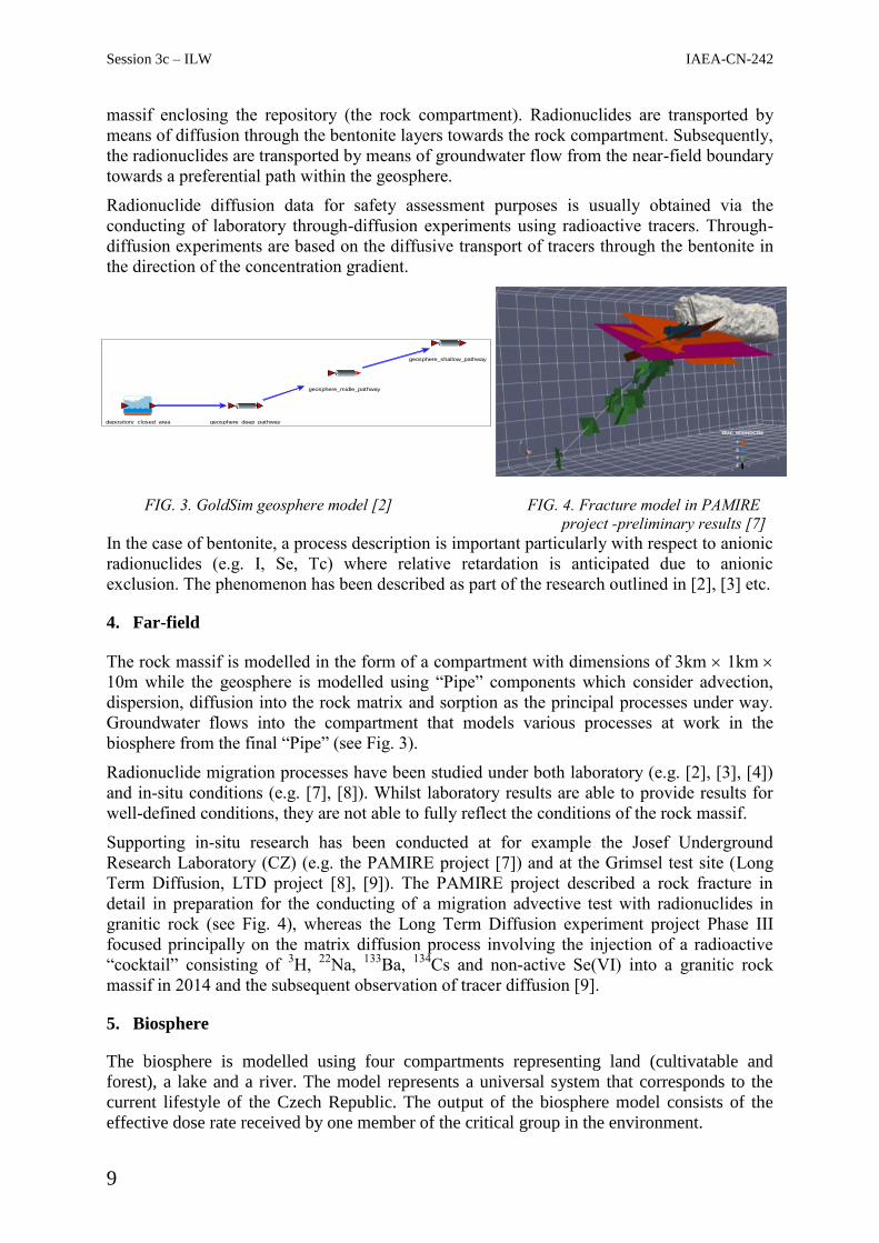
massif enclosing the repository (the rock compartment). Radionuclides are transported by
means of diffusion through the bentonite layers towards the rock compartment. Subsequently,
the radionuclides are transported by means of groundwater flow from the near-field boundary
towards a preferential path within the geosphere.
Radionuclide diffusion data for safety assessment purposes is usually obtained via the
conducting of laboratory through-diffusion experiments using radioactive tracers. Through-
diffusion experiments are based on the diffusive transport of tracers through the bentonite in
the direction of the concentration gradient.
FIG. 3. GoldSim geosphere model [2]
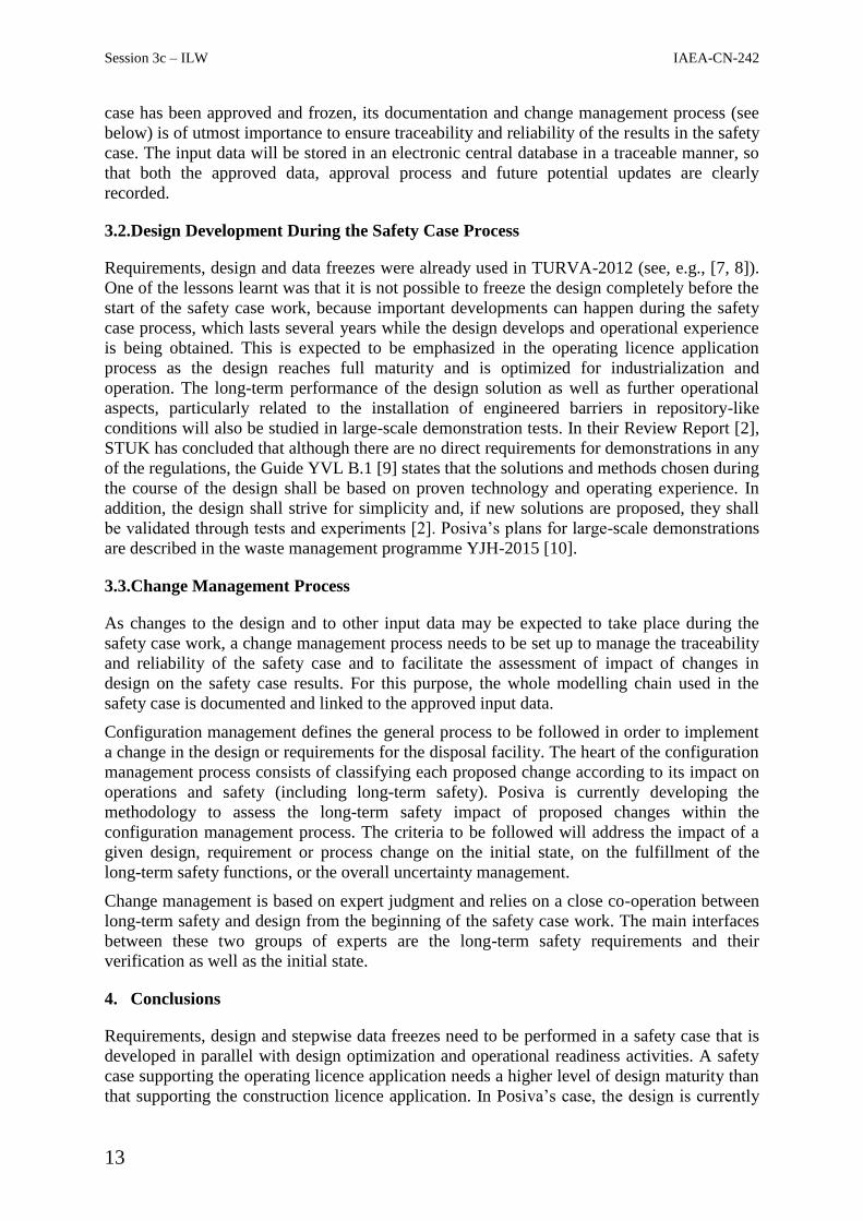
FIG. 4. Fracture model in PAMIRE
project -preliminary results [7]
In the case of bentonite, a process description is important particularly with respect to anionic
radionuclides (e.g. I, Se, Tc) where relative retardation is anticipated due to anionic
exclusion. The phenomenon has been described as part of the research outlined in [2], [3] etc.
4. Far-field
The rock massif is modelled in the form of a compartment with dimensions of 3km 1km
10m while the geosphere is modelled using “Pipe” components which consider advection,
dispersion, diffusion into the rock matrix and sorption as the principal processes under way.
Groundwater flows into the compartment that models various processes at work in the
biosphere from the final “Pipe” (see Fig. 3).
Radionuclide migration processes have been studied under both laboratory (e.g. [2], [3], [4])
and in-situ conditions (e.g. [7], [8]). Whilst laboratory results are able to provide results for
well-defined conditions, they are not able to fully reflect the conditions of the rock massif.
Supporting in-situ research has been conducted at for example the Josef Underground
Research Laboratory (CZ) (e.g. the PAMIRE project [7]) and at the Grimsel test site (Long
Term Diffusion, LTD project [8], [9]). The PAMIRE project described a rock fracture in
detail in preparation for the conducting of a migration advective test with radionuclides in
granitic rock (see Fig. 4), whereas the Long Term Diffusion experiment project Phase III
focused principally on the matrix diffusion process involving the injection of a radioactive
“cocktail” consisting of 3H,
22Na,
133Ba,
134Cs and non-active Se(VI) into a granitic rock
massif in 2014 and the subsequent observation of tracer diffusion [9].
5. Biosphere
The biosphere is modelled using four compartments representing land (cultivatable and
forest), a lake and a river. The model represents a universal system that corresponds to the
current lifestyle of the Czech Republic. The output of the biosphere model consists of the
effective dose rate received by one member of the critical group in the environment.
geosphere_deep_pathway
geosphere_shallow_pathway
geosphere_midle_pathway
depository_closed_area

Session 3d– HLW IAEA-CN-242
10
6. Conclusions
The SA model was not designed as a “static” model, rather the aim is to continue the
development of the model so as to eventually describe the site finally chosen for the Czech
DGR. The following aspects should be considered in the near term: the source term, the
refinement of the geosphere transport model, the construction of individual biosphere models
for each DGR candidate site, uncertainty evaluations etc. Work to date will be concluded
with an SA evaluation due to be completed in 2018 which will address in greater detail one of
the potential sites for the construction of the Czech deep geological repository.
7. Acknowledgement
The research presented in this study was funded by SURAO [2, 3, 5, 8], the Ministry of Trade
and Industry [6] and the Czech Technology Agency (TAČR) [7].
REFERENCES
[1] NEA-OECD (2012): Methods for the Safety Assessment of Geological Disposal Facilities
for Radioactive Waste (MeSA). NEA No. 6923, OECD, 2012.
[2] Scientific support of DGR safety assessment. SURAO project (2014 - 2016).
[3] Research and development of a disposal canister for SNF deep geological disposal.
SÚRAO project (2013 - 2017).
[4] Research of material properties for the safe disposal of radioactive wastes and the
development of procedures for their evaluation. MPO TIP FR TI-1/362 project.
[5] http://www.grimsel.com/gts-phase-vi/macote-the-material-corrosion-test/macote-
introduction
[6] Research on the influence of inter-grain granite permeability for safe disposal in a
geological formation; methodology and measurement device development; MPO TIP FR
TI-1/367
[7] PAMIRE - http://www.ujv.cz/cz/pamire. TA04020986 .
[8] Long-term diffusion Phase VI. project - http://www.grimsel.com/gts-phase-vi/ltd/ltd-
introduction
[9] Soler J. and Martin A. (2015): LTD Experiment Monopole 2: Predictive Modeling and
Comparison with Initial Monitoring Data. NAGRA Report 15-33. NAGRA, Wettingen,
Switzerland.

Session 3c – ILW IAEA-CN-242
11
03d – 02 / ID 130. Disposal of High Level Waste
PREPARING POSIVA’S POST-CLOSURE SAFETY CASE TOWARDS THE
OPERATIONAL PHASE
A. Hagros1, H. Reijonen
1, B. Pastina
2, N. Marcos
1, P. Hellä
1
1Saanio & Riekkola Oy, Helsinki, Finland
2Posiva Oy, Eurajoki, Finland
E-mail contact of main author: [email protected]
Abstract. Posiva Oy is currently preparing a safety case to support the operating licence application (OLA)
for the spent nuclear fuel disposal facility under construction at the Olkiluoto site in south-western Finland. The
methodology to prepare the safety case documentation will consider the latest updates in the regulations; lessons
learned from Posiva’s previous safety case, TURVA-2012, submitted in the context of the construction licence
application (CLA) in 2012; the feedback received from the Radiation and Nuclear Safety Authority (STUK) on
the CLA, including several specific requirements for the next safety case; and new challenges related to the
implementation of repository construction and operation. This calls for a higher level of maturity in both the
safety case itself and in the design on which the safety case is based. Since the safety case work will inevitably
take several years, it is necessary to introduce requirements, design and data freezes at the beginning of the
safety case production process. The design freeze is based on the information and requirements available at the
start of the safety case work, but updates can be expected as the design matures and is optimized for
industrialization and operation. A change management process is set up to facilitate the assessment of the
impacts of the proposed changes on the safety case results. The input data used in the safety assessment and
their possible updates will be managed by using of a central database. The uncertainties in the initial state of the
components of the disposal facility will be tackled by implementing an analysis of potential deviations in these
components at the time of installation. Deviations are then screened and implemented in scenario formulation.
Defining a range of initial state parameter values and deviations for the installed components introduces some
flexibility in design and increases the robustness of the safety case.
Key Words: Spent nuclear fuel repository, long-term safety, safety case, Olkiluoto
1. Introduction
Posiva Oy is responsible for the disposal of spent nuclear fuel from the Finnish nuclear power
plants of Loviisa and Olkiluoto. In November 2015, the Finnish Government granted a
construction licence for Posiva’s disposal facility at Olkiluoto, in south-western Finland. The
construction licence application was supported by a safety case, TURVA-2012 [1], which
was evaluated by the Radiation and Nuclear Safety Authority (STUK). STUK concluded that
Posiva had developed a safety concept that is in line with the regulatory requirements [2] and
that the post-closure safety of the disposal facility has been analyzed in a sufficient manner
for the purposes of the construction licence stage [3]. At the moment, Posiva is in the process
of preparing a safety case to support the operating licence application (OLA) for the disposal
facility. Before the application can be submitted, Posiva will have to fulfil 34 requirements
formulated by STUK for the new safety case and the related research and modelling work [3].
The new safety case will also need to consider any updates in the regulations, as well as new
challenges related to the implementation of repository construction and operation.
2. Overall Safety Case Methodology
A safety case is the synthesis of evidence, analyses and arguments that quantify and
substantiate the claim that the repository will be safe after closure and beyond the time when

Session 3d– HLW IAEA-CN-242
12
active control of the facility can no longer be assumed [4]. A safety case includes a
quantitative and a qualitative assessment of the long-term performance of the disposal
system. The quantitative assessment (a.k.a. safety assessment) is defined as the process of
systematically analyzing the ability of the disposal facility to provide the safety functions and
to meet the requirements and of evaluating the potential radiological hazards and compliance
with the safety requirements. The qualitative assessment broadens the scope of the safety
assessment to include the compilation of a wide range of evidence and arguments that
complement and support the reliability of the results of the quantitative analyses [5].
The general safety case structure builds upon the one used in TURVA-2012 [1], i.e. the safety
case will consist of a portfolio of main reports and a number of supporting reports.
2.1.Handling uncertainties in the initial state
Design development work is moving towards implementation stage and, accordingly, Posiva
has planned the disposal operation at a very detailed level, both in order to plan and optimize
the disposal operation, but also for production and large-scale implementation tests. The
experience obtained to date is used in the safety case to better constrain the uncertainties
related to the initial state of the repository system. Initial state refers to the description of the
state of various repository components after emplacement has been completed, i.e.
information which acts as a starting point for the performance and safety assessments.
The uncertainties are handled through a systematic screening of the possible deviations
through a modified failure mode and effect analysis (FMEA [6]), and further handling in the
scenario formulation work incorporating the deviations into the safety case. The FMEA for
the initial state has been modified to screen events that can lead to failure modes that are
likely to be undetected and thus remain in the repository at the time of the initial state. The
aim is to improve the description of the initial state of the repository system from the
traditional design freeze description [7] towards a description of the repository in ‘as-built’
state.
2.2.Handling uncertainties during the long-term evolution
Uncertainties during the long-term evolution of the disposal system are handled through a
systematic analysis of how the different FEPs might act on the components of the disposal
system during its evolution, followed by the formulation of scenarios and analysis of cases
giving rise to potential failures of containment and radionuclide releases and their
corresponding radiological impacts.
3. Methodology to Handle Changes
3.1.Requirements, Design and Data freezes
Since the safety case work will inevitably take several years, it is necessary to introduce
requirements, design and data freezes at the beginning of the safety case production process.
The requirements freeze allows the design to be fixed for specific purposes, such as the safety
case or large-scale tests. The design freeze is based on the information available at the time of
requirements freeze. The data freeze refers to data other than actual design data and includes,
for example, geological site data, surface environment data or time-dependent data needed in
the modelling chain, where the output of certain models will serve as input to other models.
The data freeze does not need to happen at the same time as the design and requirements
freeze, only at the time it is needed as input in the modelling chain. Once input to the safety
Session 3c – ILW IAEA-CN-242
13
case has been approved and frozen, its documentation and change management process (see
below) is of utmost importance to ensure traceability and reliability of the results in the safety
case. The input data will be stored in an electronic central database in a traceable manner, so
that both the approved data, approval process and future potential updates are clearly
recorded.
3.2.Design Development During the Safety Case Process
Requirements, design and data freezes were already used in TURVA-2012 (see, e.g., [7, 8]).
One of the lessons learnt was that it is not possible to freeze the design completely before the
start of the safety case work, because important developments can happen during the safety
case process, which lasts several years while the design develops and operational experience
is being obtained. This is expected to be emphasized in the operating licence application
process as the design reaches full maturity and is optimized for industrialization and
operation. The long-term performance of the design solution as well as further operational
aspects, particularly related to the installation of engineered barriers in repository-like
conditions will also be studied in large-scale demonstration tests. In their Review Report [2],
STUK has concluded that although there are no direct requirements for demonstrations in any
of the regulations, the Guide YVL B.1 [9] states that the solutions and methods chosen during
the course of the design shall be based on proven technology and operating experience. In
addition, the design shall strive for simplicity and, if new solutions are proposed, they shall
be validated through tests and experiments [2]. Posiva’s plans for large-scale demonstrations
are described in the waste management programme YJH-2015 [10].
3.3.Change Management Process
As changes to the design and to other input data may be expected to take place during the
safety case work, a change management process needs to be set up to manage the traceability
and reliability of the safety case and to facilitate the assessment of impact of changes in
design on the safety case results. For this purpose, the whole modelling chain used in the
safety case is documented and linked to the approved input data.
Configuration management defines the general process to be followed in order to implement
a change in the design or requirements for the disposal facility. The heart of the configuration
management process consists of classifying each proposed change according to its impact on
operations and safety (including long-term safety). Posiva is currently developing the
methodology to assess the long-term safety impact of proposed changes within the
configuration management process. The criteria to be followed will address the impact of a
given design, requirement or process change on the initial state, on the fulfillment of the
long-term safety functions, or the overall uncertainty management.
Change management is based on expert judgment and relies on a close co-operation between
long-term safety and design from the beginning of the safety case work. The main interfaces
between these two groups of experts are the long-term safety requirements and their
verification as well as the initial state.
4. Conclusions
Requirements, design and stepwise data freezes need to be performed in a safety case that is
developed in parallel with design optimization and operational readiness activities. A safety
case supporting the operating licence application needs a higher level of design maturity than
that supporting the construction licence application. In Posiva’s case, the design is currently

Session 3d– HLW IAEA-CN-242
14
being optimized for industrialization and operation and large-scale demonstrations are also
taking place, the handling of changes arising from these activities is a major challenge in the
safety case process.
As some uncertainties in the initial state of the repository components can be assumed to
remain, an analysis of potential deviations in these components at the time of installation is
proposed to be implemented. The uncertainties in the initial state can then be taken into
account in the formulation of scenarios.
A change management process needs to be set up to incorporate changes in a controlled way,
so that their long-term safety impacts are properly assessed. The proposed changes need to be
considered holistically, including the impact not only on long-term safety but also on the
safety case production process. The proposed changes will only be accepted if they do not
compromise long-term safety and if the safety case analyses can be updated using the new
input. Considering the long operational phase (over 100 years) of the disposal facility, further
optimization activities are expected to occur as the operational experience and knowledge
bases develops; a change management process is thus needed also after the operations have
started.
5. References
[1] POSIVA OY, Safety Case for the Disposal of Spent Nuclear Fuel at Olkiluoto –
Synthesis 2012, POSIVA 2012-12, Eurajoki (2012).
[2] RADIATION AND NUCLEAR SAFETY AUTHORITY, STUK’s Review on the
Construction License Stage Post Closure Safety Case of the Spent Nuclear Fuel Disposal
in Olkiluoto, STUK-B 197, Helsinki (2015).
https://www.julkari.fi/bitstream/handle/10024/127160/stuk-b197.pdf
[3] RADIATION AND NUCLEAR SAFETY AUTHORITY, Safety Case for the Disposal of
Spent Nuclear Fuel in Olkiluoto: Decision, Presentation Memorandum, 1/H42252/2015,
Helsinki (2015).
[4] NUCLEAR ENERGY AGENCY, Post-Closure Safety Case for Geological Repositories:
Nature and Purpose, Report 3679, Paris (2004).
[5] POSIVA OY, Safety case plan 2008, POSIVA 2008-05, Eurajoki (2008).
[6] STAMATIS, D.H., Failure Mode and Effect Analysis: FMEA from Theory to Execution.
ASQ Quality Press (2003).
[7] POSIVA OY, Safety Case for the Disposal of Spent Nuclear Fuel at Olkiluoto –
Description of the Disposal System 2012, POSIVA 2012-05, Eurajoki (2012).
[8] POSIVA OY, Safety Case for the Disposal of Spent Nuclear Fuel at Olkiluoto – Design
Basis 2012, POSIVA 2012-03, Eurajoki (2012).
[9] RADIATION AND NUCLEAR SAFETY AUTHORITY, Safety Design of a Nuclear
Power Plant, Guide YVL B.1, Helsinki (2014).
http://plus.edilex.fi/stuklex/en/lainsaadanto/saannosto/YVLB-1
[10] POSIVA OY, YJH-2015 Nuclear waste management at Olkiluoto and Loviisa power
plants: Review of current status and future plans for 2016–2018 (in Finnish), YJH-2015,
Eurajoki (2015).

Session 3c – ILW IAEA-CN-242
15
03d – 03 / ID 145. Disposal of High Level Waste
ANDRA’S SAFETY OPTIONS OF FRENCH UNDERGROUND FACILITY CIGÉO –
A MILESTONE TOWARDS THE LICENSING APPLICATION
S. Voinis, M. Rabardy, L. Griffault
Andra, French National Radioactive Waste Management Agency, Parc de la Croix Blanche,
92298 Châtenay-Malabry, France
E-mail contact of main author: [email protected]
Abstract. Following the publishing of the Dossier 2005 Argile, the 28th June 2006 Act entitled “Programme
National de Gestion des Matières et Déchets Radioactifs” (National program for radioactive waste and nuclear
material management) [5] has set the deep geological repository in clay host rock as the selected solution for IL-
LL and HL radioactive waste disposal in France. According to this 2006 Act, reversible waste disposal in a deep
geological formation and corresponding studies and investigations shall be conducted with a view to selecting a
suitable site and to designing a repository. Since 2011, the project has entered an industrial design development
phase and has become the Industrial Center for Geological Disposal “Cigéo”.
In view of the licensing application, two main milestones for safety are identified for Cigéo: a Safety Options
Dossier “DOS” early 2016 and the safety case to support Future License Application of Cigéo “RPs” in 2018.
According to the 2007 French Act, the Safety Options is an opportunity for the operator to send in advance a
first safety case to the French Safety Authority in order to stabilize the safety strategy, the safety requirements,
the safety methods, key safety and design options, the list of safety scenario that are selected and a preliminary
impact of a few margin scenarii. The Safety options don’t present the overall safety demonstration that needs to
be presented in the safety case supporting the licensing application. The Cigeo geological disposal facility
project is designed to cater for all the HLW and ILWLL that has been produced and will be produced by
existing nuclear facilities.
Andra has conducted in the frame of the safety options a parallel and coordinated operation and post-closure
safety analysis. Those safety options take into account the particularity of Cigéo: HLW and various types of
ILWLL waste; the step by step development of Cigeo and the balancing approach between safety, technology
and economics. Considering the various families and nature of the ILWLL waste, the Safety Options consist in
establishing “dimensioning characteristics “for design and operational safety as well as “envelop inventory” to
manage the knowledge acquired at this stage. In addition, the classification of scenario and the safety approach
are adapted to the operational and post-closure context. The safety options identify the links between the two
phases.
Key Words: nuclear safety, disposal, waste management, safety options
1. Introduction
The purpose of the Cigeo geological disposal facility for HLW and ILW-LL is to allow the
safe disposal of IL-HL LL radioactive waste in order to eliminate or reduce the burden to be
borne by future generations, in accordance with Article L542-1 of the Environment Code.
Since 1991, successive safety milestones were implemented, based on the acquisition of
scientific and technical knowledge and the development of safety methods appropriate to
deep geological disposal. Since 2011, Cigéo has entered an industrial design development
phase. In view of the licensing application, as a key milestones for safety, the Andra Safety
Options Dossier “DOS” early 2016 is submitted to a national review and an international

Session 3d– HLW IAEA-CN-242
16
review1. According to the 2007 French Act, the Safety Options is an opportunity for Andra to
send in advance a first safety case and aims to stabilize the safety strategy, the waste
inventory, safety requirements, the safety methods, key safety and design options, the list of
safety scenarios and a preliminary impact of a few margin scenarios. The safety options apply
to the disposal of high-level waste (HLW) and intermediate-level long-lived waste (ILW-LL).
The Safety options don’t present the overall safety demonstration that will be presented
in the safety case to support Future License Application of Cigéo in 2018 according to
the recent French Act of July 2016.
FIG. 1. a step-by-step iterative process as regards safety since 1991
2. Safety options and the incremental development of Cigéo
The safety options consider the duration of operation for over a hundred years with
successive phases (construction/operation); it has to be flexible enough to adapt to possible
changes in France's energy policy. There are three main phases in the life of Cigeo: (i) an
initial design and initial construction phase, (ii) an operation phase (including an industrial
pilot phase) and (iii) a post-closure phase. Cigeo will be closed in stages and the post-closure
phase will begin when the final closure of Cigeo has been authorised by a law.
FIG 2. Diagram showing the main phases in the life of Cigeo
Following final closure, the underground facility after its final closure, will be the facility as
built. At the stage of the safety options, the underground layout is only an illustration of what
Cigéo might be, based on the technical options chosen at this stage. According to the
1 International review by expert from regulatory and IAEA on behalf of the French Safety Authority

Session 3c – ILW IAEA-CN-242
17
incremental development of Cigéo, if a new technological solution is suggested, it will be
checked that the operational and post-closure safety functions are still fulfilled (safety
indicator assessment) and the radiological impact remains as low as reasonably possible
given economic and social factors.
3. The disposal system (natural and engineered components) relies on both operational
and post-closure safety principles and safety functions
Protecting people and the environment is primarily based on the performance of safety
functions during operation comparable to those performed at all nuclear facilities, and on
safety standards (national and international), safety requirements and safety options adapted
to the specific underground environment of the Cigéo facility.
Andra has implemented, from the design stage (since the 90’s), a safety approach and process
(including siting), which relies on the specific characteristics of a repository as such: (i) the
choice of the Callovo-Oxfordian formation in which the underground facility of Cigeo is
located that meets the site technical criteria of the 2008 ASN nuclear safety guide, (ii) an
underground facility located at a depth of around 500 m, of reduced geometry and long
connecting drifts, requiring specific operating, intervention and evacuation conditions; (iii) a
disposal facility being developed in successive phases, implying a need to consider the risks
related to performing underground construction work and nuclear operations in parallel; (iv) a
coordinated approach encompassing operating safety and post-closure safety. The approach
integrates the successive iterations of Cigéo milestones including design and scientific
knowledge evolutions with the objective of ensuring post-closure safety throughout the entire
development cycle of the Cigeo project.
An appropriate level of monitoring and control will be also applied to Cigeo from its
construction and during its operation, to ensure the protection and preservation of the passive
post-closure safety features, as necessary, so that they can fulfil their safety functions once
the repository is closed.
During operational phase, five safety functions are applicable to Cigeo throughout the
operating phase and must be maintained in all incident or accident situations of internal or
external origin or, at least, restored within time limits consistent with the objectives of
protecting people and the environment defined for the Cigeo project. They are: (i) contain
radioactive substances to protect against the risk of their dispersion; (ii) protect people from
exposure to ionising radiation; (iii) manage safety with regard to the criticality risk; (iv)
remove the heat produced by waste and (v) remove gases formed by radiolysis in order to
manage explosion risks.
For the post-closure phase, the Cigéo aims to isolate the waste from humans and the
biosphere and to confine it within a deep geological formation to prevent dissemination of the
radionuclides contained in this waste (see table 1). The post-closure disposal system relies
particularly on the Callovo-Oxfordian that plays the main role, and the closure structures of
the surface-to-bottom connections (sealed shafts and ramps). The global approach to post-
closure safety assessment is based on practical expression of the safety functions and
associated requirements, analysis of component performance and analysis of the uncertainties
related to the scientific and technological knowledge underpinning the design. To fulfil the
post-closure safety functions, design principles for Cigeo and for the choice of site (see
examples in table 1) are established.

Session 3d– HLW IAEA-CN-242
18
TABLE I: Example of Safety Principles for Cigéo
Post-closure safety functions General principles in terms of choice of site and design
Isolating waste from surface phenomena
and human actions Location of Cigeo at a depth and in an area of low, uniform
geodynamic
Preventing the circulation of water Low water flows in the Callovo-Oxfordian due to its low
permeability and the low hydraulic head gradient;
Consolidation and sealing of the surface-to-bottom connections
Restricting the release of radionuclides
and toxic elements and immobilising
them in the repository
Cells (particularly the materials used for them) designed to protect
the waste and packages from a physicochemical point of view
Delaying and reducing radionuclide
migration
Thickness of Callovo-Oxfordian (at least 130 m), high retention
capacity…
Optimised geometries of the cells and drifts in the underground
installation, particularly in terms of length.
Whether the disposal system is functioning correctly and more specifically whether the safety
functions are being fulfilled (operation normal functioning and post-closure normal
evolution,) the design options relies also on the results of the risks analysis during operational
phase adapted to Cigéo context (mainly transfer of waste package, co-activity of works and
operation..) and the subsequent scenario (e.g. dimensioning waste characteristics and
scenarios). It also relies on the scientific and technological uncertainties analysis after closure
and the resulting normal evolution, altered evolution and what-if scenarios assessment. In the
case of Cigéo, the safety options present a series of scenarios considering the dysfunction of
sealing, the dysfunction of vitrified waste canister, as well the occurrence of inadvertent
human intrusions (mostly borehole for Cigéo). Quantitative evaluations aimed at considering
“envelop” situations of those scenarios.
FIG 3. Diagram showing the coordinated approach to operating safety and post-closure safety

Session 3c – ILW IAEA-CN-242
19
REFERENCES
[1] Act 91-1381 of 30 December 1991 on radioactive waste management research. (1992).
Official Journal of the French Republic Acts and Decrees No. 1, 10 p.
[2] Act 2006-739 of 28 June 2006 on the sustainable management of radioactive material and
waste. (2006). Official Journal of the French Republic. Acts and Decrees No. 93, 9,721 p.
[3] Délibération du conseil d'administration de l'Agence nationale pour la gestion des déchets
radioactifs du 5 mai 2014 relative aux suites à donner au débat public sur le projet
CIGEO. Ministère de l'écologie, du développement durable et de l'énergie (2014). Journal
Officiel. Lois et décrets, n°108, pp.7851-7854.
Safety Options Report – Post-Closure Part (DOS-AF). Andra. (2015). °
CGTEDNTEAMOASR20000150062.
[4] Safety Options Report – Operation Part (DOS-Expl). Andra. (2015). °
CGTEDNTEAMOASR20000150080.
[5] Act No. 2006-686 of 13 June 2006, as amended, on transparency and security in the
nuclear field. Consolidated version dated 12 July 2014. (2006).
[6] Order of 7 February 2012 laying down the general rules on basic nuclear installations
Consolidated version dated 05 July 2013. (2012).
[7] NEA IGSC Scenario Development Workshop, 1-3 June 2015, Issy-les-Moulineaux,
France , to be published, OCDE.
[8] Radioactive Waste Disposal Facilities Safety Reference Levels v2.2. (Wgwd),
W.G.O.W.a.D. Western European Nuclear Regulators Association (WENRA). (2014). 81
p.
[9] Fundamental safety principles. Safety fundamentals. IAEA. (2006). IAEA safety
standards series n°SF-1. 37 p.
[10] Disposal of Radioactive Waste. Specific Safety Requirements. IAEA. (2011). IAEA
Safety Standards Series n°SSR 5. 62 p.
[11] The management system for facilities and activities. Safety Requirements. IAEA.
(2006). IAEA Safety Standards Series n°GS-R-3. 27 p.
[12] Monitoring and Surveillance of Radioactive Waste Disposal Facilities. Specific Safety
Guide. IAEA. (2014). IAEA Safety Standards Series n°SSG-31. 96 p.
[13] The Safety Case and Safety Assessment for the Disposal of Radioactive Waste.
Specific safety guide. IAEA. (2012). IAEA Safety Standards Series n°SSG-23. 140 p.
[14] Geological Disposal Facilities for Radioactive Waste. Specific Safety Guide. IAEA.
(2011). IAEA Safety Standards Series n°SSG 14. 104 p.
[15] The management system for the disposal of radioactive waste. Safety guide. IAEA.
(2008). IAEA safety standards series n°GS-G-3.4. 85 p.

Session 3d– HLW IAEA-CN-242
20
03d – 04 / ID 172. Disposal of High Level Waste
BRIDGING NUCLEAR SAFETY, SECURITY AND SAFEGUARDS AT GEOLOGICAL
DISPOSAL OF HIGH LEVEL RADIOACTIVE WASTE AND SPENT NUCLEAR
FUEL
I. Niemeyer, G. Deissmann, D. Bosbach
Forschungszentrum Jülich GmbH, IEK-6: Nuclear Waste Management and Reactor Safety
E-mail contact of main author: [email protected]
Abstract. In order to consider geological disposal of high-level radioactive waste and spent nuclear fuel in all
its complexity, related nuclear safety, security and safeguards issues have to be taken into account. By
identifying both synergies in overlapping methods or techniques and differences in the requirements with
respect to safety, security and safeguards, advantage of inherent synergies and conflicting requirements can be
taken at the same time. While there is a general understanding of the potential benefits of the 3S concept, neither
the interfaces and synergies between safety, security and safeguards nor their practical implementation are yet
fully understood. This paper discusses the role and importance of safety, security and safeguards regarding the
geological disposal of high-level radioactive waste and spent fuel.
Key Words: Safety; security; safeguards; 3S
1. Introduction
The use of the terms ‘nuclear safety’, ‘nuclear security’ and ‘nuclear safeguards’ is often not
sharply delimited from each other, though definitions for each of these issues exist.
According to IAEA definitions, ‘nuclear safety’ refers to “[t]he achievement of proper
operating conditions, prevention of accidents or mitigation of accident consequences,
resulting in protection of workers, the public and the environment from undue radiation
hazards” [1], and therefore stands for the safe operation of nuclear installations.
‘Nuclear security’ implies “[t]he prevention and detection of, and response to, theft,
sabotage, unauthorized access, illegal transfer or other malicious acts involving nuclear
material, other radioactive substances or their associated facilities” [1] and is aimed at the
physical protection of nuclear installations.
‘Nuclear safeguards’ are “designed to ensure that special fissionable and other materials,
services, equipment, facilities, and information made available by the Agency or at its request
or under its supervision or control are not used in such a way as to further any military
purpose” [2] or, in short, to ensure the peaceful use of nuclear material.
The interaction or intersections of the three components depend on the context, and the
significance of each of the components may vary for different types of nuclear installations.
In order to consider geological disposal of high-level radioactive waste and spent nuclear fuel
in its full complexity, all related nuclear safety, security and safeguards issues must be taken
into account. While safety can benefit from some provisions regarding safeguards and
physical protection (security), it may also be contravened by others. Some techniques for
monitoring geological repositories, such as environmental sampling, could provide relevant
data for safety, security and safeguards. Other techniques, such as geophysical measurements
for safeguards verification, are to be implemented in a way that does not infringe long-term
safety requirements. Therefore, identifying both synergies in overlapping methods or

Session 3c – ILW IAEA-CN-242
21
techniques or with respect to their future development as well as differences in the
requirements with respect to safety, security and safeguards may help to take advantage of
inherent synergies and conflicting requirements at the same time.
The need of integrating the three ‘S’s’, also referred to as the ‘3S concept’, to the extent
possible throughout all the stages of the nuclear installations’ life cycle, was recognized by
the IAEA in 2008 [3,4] and at the same time, the G8 countries declared to support the 3S
concept [5,6] . Since then, a number of papers discussed the benefits of considering a 3S
approach [e.g., 7-9] in designing and operating nuclear facilities, but only a few addressed the
issue of applying 3S to geological disposal of high-level radioactive waste and spent nuclear
fuel [10-12].
While there is a general understanding of the potential benefits of the 3S concept, neither the
interfaces and synergies between safety, security and safeguards nor their practical
implementation are fully understood to date. This also applies to the geological disposal of
high-level radioactive waste and spent nuclear fuel. Numerous legislations, regulations and
other documents have emphasized that safety is the primary requisite in all life cycle stages
of geological repositories. But what is the significance of security and safeguards with respect
to geological disposal?
2. Role and importance of safety, security and safeguards regarding the geological
disposal of high-level radioactive waste and spent nuclear fuel
2.1.Legal and organizational framework
Nuclear safety, security and safeguards legislations are laid down in a series of national and
international agreements, conventions and regulations [13]. With reference to the 3S concept,
the IAEA noted the need for nuclear legislation that reflects the interrelations between safety,
security and safeguards in a comprehensive and synergetic manner [14]. Accordingly, any
new or revised nuclear legislation on geological disposal of high-level radioactive waste and
spent nuclear fuel should also take 3S conflicts and interfaces into account.
Safety and security are mainly based on an appropriate national legal and organizational
framework, including national regulatory oversight of safety and national law enforcement in
case of security threats. Safeguards, however, represents an international legal commitment,
determined by safeguards agreements and additional protocols between States and the IAEA
[15]. States under safeguards verification by the IAEA usually have a national or regional
Safeguards Regulatory Authority (SRA) in place that acts as interface between the State and
the IAEA. Some States, such as Finland and Japan, have established national regulatory
bodies that cover safety, security and safeguards issues of their nuclear installations and
programmes, including geological disposal, in a single organization [10].
2.2.Material concerned
Safe geological disposal requires a stable geological formation to provide for the long term
containment of radionuclides and their isolation from the biosphere. Safety therefore
addresses all types of radionuclides, in particular the long-lived ones (with half-life periods in
the order of up to 107 years), i.e. actinides and long-lived fission and activation products.
Security considers nuclear material and other radioactive material [1], and safeguards are
principally applied to all source (uranium, thorium) or special fissionable material containing
uranium or plutonium [2]. The lowest common denominator of a 3S control of nuclear

Session 3d– HLW IAEA-CN-242
22
material in high-level waste and spent nuclear fuel would therefore include uranium,
plutonium and thorium.
2.3.Timelines
The safety case and safety assessment for geological disposal facilities consider the three life
cycle stages, i.e. the pre-operational period, the operational period and the post-closure
period, spanning over periods in the order of thousands of years and potentially longer (i.e. up
to hundreds of thousands of years) [16]. Security measures do address the three life cycle
stages as well, with a focus on the pre-operational and operational periods, although a
generally care and maintenance free post-closure phase is stipulated in the regulations in
various countries. The timeline for safeguards activities is bound by the duration of the
safeguards agreements and, in the end, will be applied as long as the Nuclear Non-
proliferation Treaty (NPT) remains in force.
A 3S assessment should thus be based on the longest timeline of the single ‘S’-components,
while the role and importance of each of the three ‘S’s’ would vary or decrease over time. If a
‘3S case’ was to be prepared instead of the safety (1S) case, the long-term post-closure period
would mainly be assessed from the safety perspective.
2.4.Control measures
Safety, security and safeguards activities include similar or complementary measures for
documenting, measuring and monitoring the inventory of radionuclides, in particular with
regard to uranium, plutonium and thorium. In order to avoid redundancy or duplication of
work and equipment, a material control and accountancy system should include practices and
procedures, as well as techniques for measurement, sealing and surveillance that fulfil the
requirements as to safety, security and safeguards to the extent possible.
2.5.Facility design
The IAEA generally considers safety, security and safeguards as essential elements in all life
cycle stages of nuclear facilities. In this context, the IAEA has issued a guidance document
[17] aimed at informing stakeholders how to design facilities for nuclear waste management
by early consideration of safeguards in the planning stage so that provisions can be better
integrated with other design requirements as to safety and security.
This approach, also referred to as ‘safeguards by design’ (SBD) should be more closely
interlocked with the 3S concept. ‘Safety, security, safeguards by design’ (3SBD), as generally
proposed by [18,19], can help to reduce efforts and costs related to nuclear waste
management and disposal.
3. Findings
Safety, security and safeguards aspects regarding the geological disposal of high-level
radioactive waste and spent fuel should be addressed and managed in a coordinated,
complementary approach. Further R&D will be needed to identify methods and technologies
(a ‘3S toolbox’) that would be best suited for the holistic consideration of safety, security and
safeguards provisions. By early consideration of conflicting requirements as to safety,
security and safeguards, their impacts on all three life cycle stages of geological disposal can
be minimized. The 3SBD toolbox should include methods and technologies for material
accountancy, nuclear measurements, containment and surveillance, environmental

Session 3c – ILW IAEA-CN-242
23
monitoring, continuity of knowledge, as well as design implications to the benefit of all
safety, security and safeguards at geological disposal.
REFERENCES
[1] INTERNATIONAL ATOMIC ENERGY AGENCY, IAEA Safety Glossary.
Terminology used in Nuclear Safety and Radiation Protection, Vienna (2007).
[2] INTERNATIONAL ATOMIC ENERGY AGENCY, IAEA Safeguards Glossary, Vienna
(2001).
[3] INTERNATIONAL ATOMIC ENERGY AGENCY, 20/20 Vision for the Future,
Background Report by the Director General for the Commission of Eminent Persons,
Vienna (2008).
[4] INTERNATIONAL ATOMIC ENERGY AGENCY, Reinforcing the Global Nuclear
Order for Peace and Prosperity – Role of the IAEA to 2020 and Beyond, Vienna (2008)
[5] G8 HOKKAIDO TOYAKO SUMMIT LEADERS DECLARATION, “World Economy,”
Paragraphs 28 and 65, Hokkaido Toyako, Japan (2008).
[6] TSUTOMU, A., NAITO, K. “The New Nexus, 3S: Safeguards, Safety, Security, and 3S-
Based Infrastructure Development for the Peaceful Uses of Nuclear Energy”, Journal of
Nuclear Materials Management (JNMM) 34(4) (2012), 6-10.
[7] KIM, H., et al., “3S (Safety, Security, and Safeguards)-by-Design for Engineering-Scale
Pyroprocessing Facility,” Proc. ESARDA Annual Meeting, 35th Annual Meeting, Bruges
(2013).
[8] LEE, N.Y., et al., “3S Culture, Its Meaning and Future Direction,” Proc. INMM 55th
Annual Meeting, Atlanta, GA (2014).
[9] SANDERS, K.E., et al., “Interfaces among Safety, Security, and Safeguards (3S) -
Conflicts and Synergies,” Proc. INMM 56th Annual Meeting, Indian Wells, CA (2015).
[10] VAJORANTA, T., “Finland’s Integrated Approach to Safety, Security, and
Safeguards,” IAEA Technical Meeting on Safety, Security and Safeguards, Vienna
(2012).
[11] MARTIKKA, E., et al., “Safeguards for a Disposal Facility for Spent Nuclear Fuel – a
Challenge for 3S,” Proc. INMM 55th Annual Meeting, Palm Desert, CA (2013).
[12] HADDAL, R., et al., “Geological Repository Safeguards: Options for the Future”,
Proc. IAEA Symposium on International Safeguards: Linking Strategy, Implementation
and People, Vienna (2014).
[13] INTERNATIONAL ATOMIC ENERGY AGENCY, Handbook on Nuclear Law,
STI/PUB/1160, Vienna (2003)
[14] INTERNATIONAL ATOMIC ENERGY AGENCY, Handbook on Nuclear Law:
Implementing Legislation, STI/PUB/1456, Vienna (2010).
[15] CHERF, A., “Legal Framework for Safety, Security and Safeguards”, IAEA
Technical Meeting on Safety, Security and Safeguards, Vienna (2012).
[16] INTERNATIONAL ATOMIC ENERGY AGENCY, The Safety Case and Safety
Assessment for the Disposal of Radioactive Waste, IAEA Safety Standards Series No.
SSG-23, Vienna (2012).

Session 3d– HLW IAEA-CN-242
24
[17] INTERNATIONAL ATOMIC ENERGY AGENCY, International Safeguards in the
Design of Facilities for Long Term Spent Fuel Management, IAEA Nuclear Energy
Series No. NF-T-3.1, Vienna (in print).
[18] STEIN, M., MORICHI, M., “Safety, Security, and Safeguards by Design: An
Industrial Approach,” ANS Nuclear Technology 179(1) (2012) 150-155.
[19] NUCLEAR DECOMMISSIONING AUTHORITY, Geological Disposal Safety,
Environmental, Security and Safeguards Principles for the Design Process, NDA
Technical Note no.13472678

Session 3c – ILW IAEA-CN-242
25
03d – 05 / ID 141. Disposal of High Level Waste
DEVELOPMENT OF THE NUMO PRE-SELECTION,
SITE-SPECIFIC SAFETY CASE
T. Fujiyama, S. Suzuki, A. Deguchi, H. Umeki
Nuclear Waste Management Organization of Japan (NUMO), Tokyo, Japan
E-mail contact of main author: [email protected]
Abstract. NUMO has developed a safety case for co-disposal of HLW and TRU waste to reflect current
boundary conditions in Japan. In particular, this involves addressing public concerns in the wake of the
Fukushima Dai-ichi nuclear power plant accident and a move by the Government to more strongly support
moving forward with siting a geological repository, involving suggesting locations that are considered to be
scientifically more suitable. This paper will provide a brief overview of this Safety Case, with a focus on
advances from the old “H12 Report”, which is considered the first generic safety case in Japan. “The NUMO
pre-selection, site-specific safety case” has been developed to provide a basic structure for subsequent safety
cases that would be applied to any selected site, emphasising practical approaches and methodology, which will
be applicable for the conditions/constraints during an actual siting process.
Key Words: Geological disposal, Safety case, Vitrified waste, TRU wastes.
1. Introduction
The “H12 Report” [1] published in 1999 by the Japan Nuclear Cycle Development Institute
(now the Japan Atomic Energy Agency, “JAEA”) demonstrated the feasibility of safe and
technically reliable geological disposal of high level waste (HLW), based on a generic study.
On the basis of the H12 Report, “the Final Disposal Act” came into force and NUMO was
established as the implementing body in 2000. Intermediate-level waste generated from
reprocessing of spent nuclear fuel and mixed-oxide fuel fabrication (termed “TRU waste” in
Japan) was also included in the inventory for disposal in 2007. NUMO has been developing
key technologies required for the safe implementation of the geological disposal project since
its establishment and initiated the siting process by open solicitation of volunteer
municipalities in 2002. So far, however, no volunteer municipality has appeared and no
candidate host rock type can be specified.
The Fukushima-Daiichi NPP accident in 2011 increased nationwide concerns about the
feasibility and reliability of safe geological disposal in Japan. After re-thinking the
implementation process, “the Basic Policy on the Final Disposal of Specified Radioactive
Waste” was amended in 2015, so that the Government now leads the search for volunteer
sites. This procedure involves nominating more suitable areas from a geo-scientific point of
view to initiate discussions and cooperation with local municipalities, finally leading to
acceptance of a site investigation, which will be carried out by NUMO.
Taking such changes in boundary conditions into account, it is important at this time for
NUMO to integrate required technologies, including the latest R&D output, in order to
confirm the feasibility and safety of geological disposal in Japan. Thus NUMO has developed
the “NUMO pre-selection, site-specific safety case” which, with the site descriptive models
(SDMs) recently developed, provides a more advanced site-specific basis than the generic
safety case in the H12 Report. This has been developed in a manner that will allow it to
provide the basic structure of future safety cases that would be applicable to any site that
might arise from the site selection process.

Session 3d– HLW IAEA-CN-242
26
2. Basic Strategy of the NUMO Safety Case
Despite the fact that there has not been a site or specific host rock identified, the NUMO
Safety Case has developed detailed geological and hydrogeological models for potential host
rock environments. Repository design and safety assessment have been thus performed for
these geological models, thereby providing underpinning evidence to demonstrate the
technical feasibility and the safety for the various types of Japanese geological environments.
More background is provided in the companion paper by Suzuki et al. [2]
3. Site Characterisation and Synthesis into SDMs
NUMO needs to prepare reliable investigation and evaluation methodologies and an approach
to synthesise their output in order to form the basis of selecting suitable repository sites. In
suitable setting, the key safety functions (isolation and containment) of the host geological
environment will persist for a long period of time. Advanced methodologies for precluding
the potential impacts of natural disruptive events and processes are shown. Key concepts,
technical knowledge bases, and basic methodology for geosynthesis of relevant information
into representative spatial and temporal models of site evolution are also documented.
The illustrative site descriptive models (SDMs) are developed for subsequent repository
design and safety assessment. Generic repository design and safety assessment were
performed in the H12 Report for two illustrative geological settings, namely crystalline rock
and sedimentary rock. However, geoscientific knowledge has expanded significantly since
then due in particular to multidisciplinary research programmes; for example, JAEA’s
underground research laboratory projects. It is thus very important to update the previous
repository design and safety assessment on the basis of the current best understanding of
Japanese geological environments in the NUMO Safety Case.
Following the categorization of all potential host rock environments, rock types are grouped
by identifying key characteristics/properties relevant to geological disposal. As a result, three
types of potential host rock environments, ‘Igneous rocks’, ‘Neogene sedimentary rocks’, and
‘Pre-Neogene sedimentary rocks’ are examined in the NUMO Safety Case.
FIG. 1. An example of the nested SDMs for Igneous rocks, including underground panel layout
(bottom, left) and EBS of HLW (bottom, right)
Realistic geological and hydrogeological models are developed in a stepwise manner for the
three types of potential host rock environments: at scales of several kilometres (repository
1km
Active fault Active fault
Granite
Highly fractured (weathered) domain
Sedimentary overburden
100~200m100~200m
GW flow
Illustrative geological setting
3 km
3 k
m
Repository scale
Regional scale
50 km ×50 km
Reserved area
Reserved area
Reserved area
Unpreferable area
Short travel time
Panel scale
Ap
pro
x.
80
0m
EBS + Rock
100m
10
0m
Near-field scale
Faults
(Length > 1km)

Session 3c – ILW IAEA-CN-242
27
scale), for defining the location and layout of a repository and assessing groundwater flow
through the potential host rock; then at several hundred metres (panel scale) and a hundred
metres (near-field scale), for more precisely describing hydraulic properties. FIG. 1 shows an
example of the geological and hydrogeological modelling for ‘Igneous rocks’ at nested
scales. For geological modelling, key geological structures that control groundwater flow and
have a major influence on solute transport, such as faults, fractures and sedimentary
structures, are represented by a combination of deterministic and stochastic modelling
approaches.
4. Repository Design
Design methodologies should be developed so as to maintain flexibility for the range of
potential geological conditions encountered in Japan. In the NUMO Safety Case, alternative
repository concepts are presented, which are applicable for a wide range of potential
geological conditions. The designed repositories should be technically feasible to construct
and fulfil the safety functions required to isolate and contain radionuclides.
The design requirements and specifications of the engineered barrier system (EBS), disposal
tunnel, panel layout and sealing system (tunnel back-filling and plugs) have been defined.
The methodology is demonstrated by carrying out a full repository design study, tailored to
the SDMs of three types of potential host rock. The engineering feasibility of construction,
operation and closure of the repository is evaluated based on techniques demonstrated in
domestic or overseas underground laboratories and related R&D facilities. The diagram in
FIG. 1 (bottom, left) illustrates an example of an underground layout tailored to the
geological and hydrogeological model for Igneous rocks. The single level emplacement panel
is applicable in this case, avoiding faults with lengths greater than 1 km (the minimum length
that can be identified by surface-based investigation), and avoiding any less preferable areas
where calculated groundwater travel times are relatively short. Optimal operational processes
and material flow logistics, ventilation and water drainage systems for the underground
facility are also considered while determining the layout. Such site-specific design
demonstrations show progress in practicality of design methodologies.
5. Safety assessment
During the siting stages, both pre- and post- closure safety will proceed in an iterative manner
and the resulting output will support decisions made at the end of each stage from the
perspective on safety. The required safety assessment technology for scenario development,
modelling, database development, etc. will be maintained at the state-of-the-art.
For pre-closure safety, it is needed to demonstrate the feasibility of radiological protection for
local residents and workers during repository operation. Learning from the Fukushima-
Daiichi NPP accident, the regulatory guidelines for nuclear facilities have been revised, but
those for geological disposal have not been discussed in detail so far. In developing
methodology for operational safety assessment of geological disposal, relevant guidelines for
other nuclear facilities, such as those for vitrified waste storage, are considered in the NUMO
Safety Case. An the first stage, radiological safety is highlighted, focusing on activities
relevant to HLW handling and transport, based on specific repository designs and defined
procedures of operation.
For post-closure safety, it is needed to develop an assessment approach and methodologies
which can be applied to specific sites and the repository design concepts tailored to them. In
the NUMO Safety Case, procedures and methodologies to assess long-term safety are

Session 3d– HLW IAEA-CN-242
28
demonstrated. A risk-informed approach is introduced, based on international guidelines as
well as recent national discussions on safety regulations. Scenarios are developed and
classified with consideration of their probability of occurrence and target doses are defined as
illustrated TABLE I. Referring to the guidelines of international organizations on assessment
timescales, dose calculations are carried out for up to one million years after closure.
TABLE I: SCENARIO CLASSIFICATION AND TARGET DOSE
Scenario classification Definition Target dose
Likely Scenario
The scenario is used to assess the performance of the
geological disposal system based on best
understanding of the probable evolution, as a
reference for the optimisation of protection.
10 μSvy-1
Less-likely scenario
The scenario is used to assess the safety of the
geological disposal system in view of uncertainties
in scientific knowledge supporting likely scenarios.
0.3 mSvy-1
Very unlikely
scenario Possible scenarios with extremely low likelihood. 1-20 mSvy
-1
Human intrusion
scenario
The scenario is used to check whether the geological
disposal system is robust with assumption of the
human intrusion after loss of institutional control.
Residents:1-20 mSvy-1
Intruder:
20-100 mSv per event
A hybrid methodology of scenario development is introduced, which combines a more
conventional, bottom-up, FEP-based approach and a top-down method based on safety
functions, appropriate to a risk-informed assessment. Safety assessment is being conducted
by applying a approach and methodology of realistic radionuclide transport modelling, as
needed to allow comparison of sites and also possible repository concepts that could be
tailored to them. This advanced modelling includes more realistically representing the
geometry of all components of the engineered barriers (essential for distinguishing between
different repository design options) and realistically representing the 3-dimensional geometry
of the geosphere, with particular emphasis on the solute transport characteristics of all
relevant formations (shown in FIG.1, bottom right). The estimated doses of scenarios in
different categories are smaller than the assumed criteria in the NUMO Safety Case. This
provides a basis for more comprehensive demonstration of post-closure safety at this stage.
The outline of assessment pre- and post- closure safety in the NUMO Safety Case is
presented in the companion paper. [2]
6. Conclusions and a look to the future
The safety case developed by NUMO is inherently limited by the lack of an actual site to
focus on, but the SDM-based approach provides critical experience in integrating the
activities of site characterisation and engineering design teams, focused by the fundamental
requirement to robustly assure safety. This will prove invaluable in the next phase when
parallel characterisation of potential sites may occur.
REFERENCES
[1] Japan Nuclear Cycle Development Institute, H12: Project to establish the scientific and
technical basis for HLW disposal in Japan, JNC-TN1410-2000-001~004, (2000).
[2] S. Suzuki, et al., “Assessment of pre- and post-closure safety in the NUMO safety case
for a geological repository”, International Conference on the Safety of Radioactive Waste
Management, IAEA, Vienna (2016) (in press).

Session 3c – ILW IAEA-CN-242
29
03d – 06 / ID 131. Disposal of High Level Waste
DEVELOPMENT OF A GENERIC ENVIRONMENTAL SAFETY CASE FOR THE
DISPOSAL OF HIGHER ACTIVITY WASTES IN THE UK
L.E.F. Bailey1, T.W. Hicks
2
1Radioactive Waste Management, Building 587, Curie Avenue, Harwell, Oxford, Didcot
OX11 0RH, UK 2Galson Sciences Limited, 5, Grosvenor House, Melton Road, Oakham, LE15 6AX, UK
E-mail contact of main author: [email protected]
Abstract. The UK is committed to implementing geological disposal for the long-term, safe management of
higher activity radioactive wastes [1]. Higher activity waste includes low-level waste not suitable for near-
surface disposal, intermediate-level waste and high-level waste. As yet, no site has been selected for a
geological disposal facility (GDF) in the UK, but it has been agreed that a site will be sought using a consent-
based approach, preceded by a national geological screening process.
Radioactive Waste Management Ltd (RWM) is responsible for the delivery of the GDF. RWM also has a role
to support the ongoing packaging of radioactive wastes and to provide disposability assessments for waste
producers to provide confidence that packaged wastes will be suitable for eventual disposal in the GDF.
To underpin its role, it is essential that RWM can demonstrate its confidence in the safety of a GDF. To this
end, RWM maintains a generic Disposal System Safety Case that addresses all safety issues concerning the
transport of radioactive wastes to a GDF, the construction and operation of a GDF and the long-term,
environmental safety of a GDF after it has been sealed and closed. It is a challenge to present a meaningful
safety case when the location and hence the design of the GDF are not known. This is particularly pertinent for
the long-term, environmental safety case (ESC), which depends significantly upon an understanding of the
geological setting of the GDF and its evolution.
This paper explains how RWM has developed a generic ESC based on an understanding of the environmental
safety functions provided by a multi-barrier disposal system and the features, events and processes (FEPs) that
support them [2]. It explains how an understanding of the basic physics and chemistry underpinning generic
GDF concepts can be used to develop ‘insight models’ to build understanding of the long-term performance of a
GDF, to support a safety narrative. The paper also explains the role of probabilistic total system models in
providing illustrative calculations to support the generic ESC and RWM’s approach to addressing the inevitable
uncertainties associated with the long timescales that need to be considered within an ESC.
Key Words: radioactive, waste, disposal, safety
1. Introduction
The environmental safety of geological disposal is achieved by isolating the wastes in a
facility constructed deep underground and ensuring that the radionuclides and non-
radiological contaminants are contained such that long-term safety is provided by passive
means. To support the development of a GDF concept that achieves environmental safety,
RWM has defined a set of long-term safety requirements that are consistent with regulatory
expectations on environmental safety. In the absence of a GDF site, while geological
screening progresses in the UK, the strategy for GDF design to meet the safety requirements
is focused on the development of illustrative concepts for radioactive waste disposal in three
generic rock types (higher strength rock, lower strength sedimentary rock and evaporite
rock). For each host rock type, illustrative GDF designs have been identified for high-heat-
generating wastes (HHGW) and low-heat-generating wastes (LHGW), based on multi-barrier
concepts that have been developed in the UK or overseas.

Session 3d– HLW IAEA-CN-242
30
2. Generic ESC strategy
The generic ESC [Error! Bookmark not defined.] focuses on a narrative that presents
RWM’s understanding of safety in the context of the illustrative disposal concepts and their
barrier system components. RWM has defined a general set of ‘environmental safety
functions’ that could be provided by different barrier system components at different times
after disposal. These environmental safety functions define how the geological environment,
wasteform, container, buffer/backfill, plugs and seals of a GDF combine to isolate and
contain the wastes and limit the transport of contaminants to the surface environment in
groundwater or gas. They also relate to how the stability of the barrier system is maintained,
how disruption of the barrier system through gas-pressurisation is avoided, and how the
potential for post-closure criticality is minimised. Each environmental safety function will be
influenced by various FEPs after disposal. For RWM’s generic ESC, the OECD NEA FEP
database [3] was reviewed to identify FEPs of potential relevance to the different GDF
concepts and the safety functions provided by the barrier systems. For example, FIG. 1
shows the waste package FEPs listed in the OECD NEA international FEP database that
could influence how a wasteform limits the release of contaminants from a waste package.
Having defined how different barriers provide environmental safety functions after disposal,
the overall environmental safety of a GDF needs to be demonstrated for all relevant scenarios
of disposal system evolution. These scenarios are identified through an analysis that
considers the timescales over which each barrier’s environmental safety functions are
expected to be effective and the situations in which barrier performance may be challenged or
compromised by probabilistic events and processes.
FIG 1 Illustration of the waste package FEPs listed in the OECD NEA international FEP database
that could influence how a wasteform limits the release of contaminants from a waste package

Session 3c – ILW IAEA-CN-242
31
By considering barrier behaviour for each illustrative disposal concept, a base scenario has
been defined that represents understanding of expected GDF evolution, with reference to the
environmental safety functions to be provided by each barrier component. Variant scenarios
for GDF evolution have been identified based on consideration of probabilistic FEPs that
may or may not occur. By assessing these scenarios, different safety states are analysed in
which wastes are contained in the engineered barrier system or in the geological barrier, or
are returned in residual amounts to the accessible environment at regulated, acceptable levels.
2.6. Evaluation strategy
It is possible to gain understanding of the post-closure performance of a GDF by considering
the basic physics of the disposal system through ‘insight modelling’. Such modelling can be
used to inform the development of appropriate disposal concepts for different generic rock
types and is particularly helpful at the generic stage because it does not require large amounts
of data. For example, the peak radiological risk arising from the migration of radionuclides
via the groundwater pathway in an advection-dominated geological environment can be
estimated using a simple one-dimensional model of radionuclide transport in a porous
medium. Such a model can be used to illustrate in terms of a set of dimensionless parameters
how peak radiological risk is low if there is a long retarded travel time in the geological
barrier relative to the rate of radionuclide decay, significant longitudinal dispersion along the
transport path through the geological barrier, or slow leaching of radionuclides from the
disposal region relative to the rate of radionuclide decay.
Insight modelling complements the more detailed probabilistic total system modelling of the
behaviour of radionuclides and non-radiological species in a disposal system that takes
account of uncertainty in system evolution. These models enable the risks associated with
geological disposal, as well as complementary indicators of safety such as activity fluxes
across barriers, to be evaluated, thus supporting understanding of the different safety states of
a GDF. Natural and archaeological analogue evidence of how barrier materials behave under
expected disposal conditions presents other lines of reasoning that support safety evaluations.
2.7. Assessment timescales
In considering appropriate assessment timescales it is relevant to consider the hazard
presented by the wastes in the GDF and the uncertainties associated with the GDF and its
environment. For the period in which a disposal system is expected to be relatively stable
and uncertainties in the behaviour of radionuclides and non-radiological contaminants can be
quantified more reliably, it is appropriate to undertake probabilistic calculations of GDF
performance. However, for periods in excess of a few hundred thousand years after GDF
closure, the geological environment could be affected by large-scale natural processes, such
as tectonism, subsidence, uplift and erosion, permafrost development and periods of
glaciation. Until specific sites have been identified as potential locations to host a GDF in the
UK, RWM considers that it is not appropriate to undertake a detailed assessment of the
impacts of large-scale natural processes on GDF performance. Thus, the generic ESC
includes probabilistic calculations for an assessment period of 300,000 years after GDF
closure to provide an indication of the barriers that are likely to be of most importance to
GDF performance on the timescales over which some large-scale natural processes could
occur. In this period, the activities of the majority of radionuclides are expected to become
insignificant as a result of radioactive decay whilst the radionuclides are contained within the
disposal system. The behaviour of relatively soluble and mobile radionuclides, such as
chlorine and iodine, and gaseous releases of radionuclides are likely to be of most

Session 3d– HLW IAEA-CN-242
32
significance to environmental safety in this period. A range of illustrative calculations of
radionuclide transport and containment have been undertaken to assess base and variant
scenarios over the 300,000-year period for the different illustrative disposal concepts.
3. Summary
The generic ESC explains how the geological disposal of higher activity wastes can be
accomplished in a way that ensures environmental safety in the long term after wastes have
been emplaced and the disposal facility has been closed. Underpinning the ESC are:
A safety concept that is based on ensuring that the long-term safety requirements for
the GDF are met.
A demonstration of how environmental safety can be achieved by implementing
disposal concepts that are based on systems of multiple engineered and natural
barriers that provide multiple safety functions. These barriers are designed to ensure
that the wastes are isolated and contained for the long term after disposal by passive
means.
An understanding of expected barrier performance and how conditions in a disposal
system will evolve, based on research findings presented in RWM’s knowledge base.
An approach to safety assessment based on multiple lines of reasoning, involving both
qualitative and quantitative analysis. Insight modelling and total system modelling
have been used to develop an understanding of how different components of the
engineered and natural barrier system contribute to environmental safety.
At the current time, no site is available for a GDF in the UK and therefore the ESC is
necessarily generic. The high-level generic safety arguments presented in this ESC provide
the understanding that will underpin the future development of a site-specific ESC. In
particular, at each stage of the development and design of the GDF, demonstration of the
post-closure safety of a disposal concept will be founded on an understanding of the
environmental safety functions that will be provided by the specific engineered barriers
defined for a particular combination of host rock and wasteform and the natural barriers
provided by the geological environment.
REFERENCES
[1] DEPARTMENT OF ENERGY & CLIMATE CHANGE, Implementing Geological
Disposal – A Framework for the Long Term Management of Higher Activity Waste,
URN 14D/235, July 2014.
[2] RADIOACTIVE WASTE MANAGEMENT, Generic Environmental Safety Case Main
Report, DSSC/203/01, in publication.
[3] NEA, Updating the NEA International FEP List: An IGSC Technical Note, Technical
Note 2: Proposed Revisions to the NEA International FEP List, NEA/RWM/R(2013)8,
OECD NEA, Paris, September 2012 (published June 2014).

Session 3c – ILW IAEA-CN-242
33
03d – 07 / ID 184. Disposal of High Level Waste
SITEX, THE EUROPEAN NETWORK OF TECHNICAL EXPERTISE
ORGANISATIONS FOR GEOLOGICAL DISPOSAL
D. Pellegrini1, F. Bernier
2, V. Detilleux
3, G. Hériard Dubreuil
4, A. Narkuniene
5, J. Miksova
6,
M. Rocher1
1Radiation Protection and Nuclear Safety Institute (IRSN), France
2Federal Agency for Nuclear Control (FANC), Belgium
3Bel V, Belgium
4MUTADIS, France
5Lithuanian Energy Institute (LEI), Lithuania
6Research Centre Rez (CV-REZ), Czech Republic
E-mail contact of main author: [email protected]
Abstract. A European SITEX network is being prepared to ensure a sustainable capability for developing and
coordinating joint and harmonized activities related to the independent Expertise Function in the field of deep
geological disposal safety. Two successive EURATOM projects devoted to the preparation of this network
worked on the needed set of activities, which entails strengthening the review of safety cases, developing a
research strategy, interacting with civil society and training. This paper presents the main outlines of the on-
going second project called SITEX-II, with a specific focus on the Strategic Research Agenda issued recently.
Key Words: Expertise Function Network, Geological Disposal, Safety Case Review, Civil Society
Involvement.
1. Introduction
The European Council Directive 2011/70/EURATOM of 19 July 2011 establishes a
Community framework for the responsible and safe management of spent fuel and
radioactive waste. In line with this Directive and in consistency with international high level
safety standards issued by IAEA and WENRA, waste management organisations (WMOs)
are developing a safety case for presenting the technical and organisational arguments that
support the development of the national geological repository in each concerned country.
As safety cases develop, the safety case review by regulatory bodies in the framework of the
decision making process develops as well. In that context, organisations in charge of
reviewing the safety case must in particular evaluate whether the elements of safety, and in
particular that supported by scientific and technological results, are sufficiently convincing to
be accepted by the regulatory authority as a basis for proceeding with the decision making
process.
In that context, there is a need at the international level for developing and coordinating
activities associated with the regulatory review process of deep geological disposal. In 2012,
the EURATOM FP7 SITEX (“Sustainable network for Independent Technical EXpertise of
radioactive waste disposal”) project was launched in order to complement existing initiatives
(ENSREG, WENRA, NEA/RWMC/Regulator Forum…) with the view to characterize the
Expertise Function (see Figure 1) devoted to the technical review of a safety case at national
level for deep geological disposal of radioactive waste.

Session 3d– HLW IAEA-CN-242
34
FIG. 1. The Expertise Function and its interactions [1].
The SITEX-II Project (2015-2017), a EURATOM Horizon2020 Coordination and Support
Action, is aimed at practical implementation of the activities defined by the former SITEX
project using the interaction modes developed by that project and with a view to further
prepare the future Expertise Function network. SITEX-II brings together, as partners,
representatives from 18 organisations involving National Regulatory Authorities (NRAs),
Technical Support Organisations (TSOs), Research Entities (REs), Non-Governmental
Organisations (NGOs), specialists in risk governance and an education institute, and involves
interactions with a wider group of Civil Society (CS) participants. Its tasks include
programming R&D, developing a joint review framework, training and tutoring for reviewing
safety cases and interacting with CS, as detailed below, together with preparing an Action
Plan that will set out the content and practical modalities of the future Expertise Function
network.
2. Programming R&D
The 2011/70/EURATOM Directive requires the Expertise Function to carry out its own
horizontal and R&D activities, so that it is not dependent on those developed by the
Implementer Function to make its own judgement. It is also stressed in IAEA safety guides
that the Regulatory Body, and thus its supporting organisations (see Figure 1), may need to
conduct or commission R&D in support of regulatory decisions (see IAEA GS-G-1.1 [2] (see
§3.33) and IAEA GS-G-1.2 [3] (see §3.68)).
SITEX-II therefore includes a task which pursues the general objective of further defining the
Expertise Function’s R&D programme necessary to ensure independent scientific and
technical capabilities for reviewing a safety case for geological disposal. In this perspective, a
Strategic Research Agenda (SRA) [4] has been issued, which will be completed by the Terms
of Reference (ToR) for its implementation. This SRA has been also an input to the JOPRAD
project (EURATOM Horizon2020 Coordination and Support Action “Towards a Joint
Programming Project on Radioactive Waste Disposal”, 2015-2017), which aim is to assess
the feasibility and, if appropriate, to generate a proposal for Joint Programming activities that
could be developed by WMOs, TSOs and/or REs in the field of Radioactive Waste
Management (RWM), in particular geological disposal.
The commitments of SITEX-II members for the development of the Expertise Function SRA
are the following:
– the SRA is developed by applying a transparent methodology;
– the SRA addresses the needs associated with the different states of advancement of
geological disposal programmes;

Session 3c – ILW IAEA-CN-242
35
– the concerns of CS participants are duly taken into consideration.
The current version of the SRA entails topics relevant to the Expertise Function to assess
whether geological disposal facilities are developed and will be constructed, operated and
closed in a safe manner, for which a sufficient level of common interest has been expressed
amongst the SITEX-II members. So, seven main topics related to pre and post-closure safety
are considered in the SRA (1. Waste inventory, 2 Transient THMBC conditions in the near-
field, 3. Evolution of EBS material properties, 4. Radionuclide behaviour in disturbed EBS
and HR, 5. Safety relevant operational aspects, 6. Managing uncertainties and the safety
assessment, 7. Lifecycle of a disposal programme and its safety case). In addition to R&D
activities, the needs for knowledge transfer (e.g. training, tutoring), for developing states of
the art and for exchanging on practices and developing common positions are also identified.
One particularly innovative development of the SRA relates to the introduction in the main
topic n°7 of several holistic (complex) topics, for which both technical and societal aspects
need to be investigated in an integrated manner, using specific interdisciplinary
methodologies and involving CS participation. Also, regarding the other main topics, that are
mainly technical, it came out essential to embed CS participation through the involvement of
trained individuals, therefore offering the public the possibility to follow the development of
this technical research, and to perform Knowledge Sharing and Interpretation (KSI) activities
along the development of R&D results
Figure 2 illustrates the associated issues and activities of common interest for Main Topic 1.
SRA Main Topic and associated issues
Research activities (experiment
and/or modeling works)
Horizontal activities
Exchange on practices, develop common positions
Develop states of the art
Transfer of knowledge
(eg. training)
Main Topic 1: Waste inventory and source term #1. Uncertainty about databases and methodologies used for
defining waste inventories(including historical waste)
#2. Evolution of the waste inventory due to possible neutron activation
#3. Understanding of the release processes and speciation of the radionuclides for spent fuel, vitrified and cemented waste
#4. Waste acceptance criteria
FIG. 2. Associated issues and activities for Main Topic 1 of the Expertise Function SRA.
3. Developing a joint review framework
High-level safety requirements and regulatory expectations for the safety case at different
phases of geological disposal facility development (conceptualization, siting, reference
design, construction, operation, post-closure) are addressed by the EU Directive and
international standards and recommendations (IAEA, ICRP, WENRA, etc.). This leads to a
key objective for a second SITEX-II task to further develop a common understanding of the
interpretation and proper implementation of safety requirements in the safety case for the six
phases named above of geological disposal facility development. Position paper on the
selected topics and technical guides related to the review of a safety case will be elaborated,
accounting for existing initiatives and building upon return of experience at the international
level. To date, SITEX-II participants have exchanged their views and experience on how to
implement in practice the requirements and expectations related to “optimisation of
protection” and to “waste acceptance criteria”. The next topics will be “operational issues in
regards with post-closure safety”, with an introductory presentation by a GEOSAF2
representative, and “programme for site characterization”.

Session 3d– HLW IAEA-CN-242
36
4. Training and tutoring for reviewing the Safety Case
The third task of the ongoing project aims to implement a practical demonstration of training
services that may be provided by the foreseen SITEX network. The training will be
undertaken within the existing institute for expert training in nuclear safety (the European
Nuclear Safety Training and Tutoring Institute, ENSTTI). The development of a training
module at a generalist level with emphasis on the technical review of the safety case is on-
going. The module will be presented and evaluated in the pilot training session in 2017.
5. Interactions with Civil Society
The quality of the decision-making process, and its compliance to international rules and
conventions, includes several requirements such as maintaining over time consultation and
interaction with interested parties in the decision-making process. It is therefore crucial for
the consistency of the SITEX-II project that interaction with CS is embedded all along the
development of the future SITEX network. This is expected to contribute to transparency in
the specific area of expertise, supporting the development of interactions between Expertise
and Society functions at different levels of governance and at different steps of the decision-
making process. SITEX-II involves, as partners, representatives of NGOs and interacts with
CS participants through workshops covering three thematic tasks, namely: R&D, safety
culture/review and governance. The results will be integrated in one deliverable addressing
the conditions and means for developing interactions with CS in the framework of the
foreseen SITEX network. The constructive discussions that took place to date within SITEX-
II allowed both institutional and CS participants to exchange and challenge their views,
fostering mutual understanding, notably through the elaboration of the SRA. The need for
building mutual understanding led to the development of – and was in turn dynamized by –
an innovative multi-stakeholders evaluation process and tool, allowing for a participative and
comparative discussion of alternative scenarios of long-term RWM which target passive
safety as their end point.
6. Conclusion
The progress to date of the EURATOM Horizon2020 SITEX-II project shows that
developing and coordinating joint and harmonized activities at the international level
supporting the independent Expertise Function is achievable and promising in the field of
geological disposal safety. Particularly, the involvement of of NGO representatives linked
with a wider group of CS participants within SITEX-II should allow the Expertise Function
to better account for societal concerns in its future networking activities, thus strengthening
the decision making process. At this stage, the launching of the Expertise Function network is
foreseen in 2018-2019, together with the Joint Programming if supported, meaning an
ambitious calendar that calls for interested organizations that are not part of the SITEX-II
project to express their interest now.
This project has received funding from the EURATOM research and training programme 2014-2018 under grant agreement
No 662152.
References
[1] EC FP7 SITEX project, “D6.1 Conditions for establishing a sustainable expertise
network”, 2014.
[2] IAEA, “Safety guide GS-G-1.1-Organization and staffing of the regulatory body for
nuclear facilities”, Vienna, 2002.

Session 3c – ILW IAEA-CN-242
37
[3] IAEA, “Safety guide GS-G-1.2-Review and assessment of nuclear facilities by the
regulatory body”, Vienna, 2002.
[4] DETILLEUX, V. et al., “Overview of the Strategic Research Agenda in the field of
geological disposal of radioactive waste developed by the Expertise Function in the EC-
H2020-SITEX-II project”, EUROSAFE Forum 2016, 7th & 8th November 2016, Munich,
Germany (in preparation).

Session 3d– HLW IAEA-CN-242
38
03d – 08 / ID 207. Disposal of High Level Waste
RESEARCH AND DEVELOPMENT NEEDS IN A STEP-WISE PROCESS FOR THE
NUCLEAR WASTE PROGRAMME IN SWEDEN
A. Ström 1, K. Pers
2, J. Andersson
1, E. Ekeroth
1, A. Hedin
1
1 Swedish Nuclear Fuel and Waste Mgmt. Co. (SKB), Stockholm, Sweden
2 SKB International AB, Stockholm, Sweden
E-mail contact of main author: [email protected]
Abstract The license holders have formed Swedish Nuclear Fuel and Waste Management Co. (SKB) to on
their behalf develop and manage a programme for the research and development activities needed to manage
and dispose of nuclear waste and spent nuclear fuel in a safe manner. The disposal of waste from
decommissioning and dismantling of nuclear power plants is also part of SKB´s assignment. Such a programme
(RD&D Programme) has since 1986 been submitted every third year to the Swedish Radiation Safety Authority
(SSM) for review as preparation for a Government decision on the programme.
After more than 30 years of research and development regarding final disposal of spent nuclear fuel, an
application under the Nuclear Activities Act for final disposal of spent nuclear fuel and an application under the
Environmental Code for the KBS-3 system was submitted in March 2011. These license applications provided a
summary of the current status of the development of the KBS-3-system and included a safety assessment. An
application to extend the existing final repository for short-lived radioactive waste was submitted in 2014.
The licensing processes are under way for both these repositories. Even though a large number of issues may be
considered resolved regarding the systems there are still substantial technology development and demonstration
efforts planned before disposal can begin and the facilities be operated as an industrial enterprise. Furthermore,
SSM's regulations specify that development and licensing of nuclear facilities will be achieved through a
stepwise process in which the requirements of the facility, its design and technical solutions is gradually
established based on research, technology development and evaluation of safety after closure.
RD&D programme 2016 was submitted in September. Adjusted to the current situation, needs for future
research and technology development is based on the stepwise decision process described above. The milestones
that are linked to major decision steps for new and extended facilities determine the required level of knowledge
and development of technology. The safety reports together with the comments made by SSM in connection
with the review of the applications, as well as audits of previous RD&D programmes, are the basis for the
programme.
Key Words: Waste disposal, spent fuel, research, technology development, safety analysis
1. Background and introduction
The Swedish power industry has been generating electricity by means of nuclear power for
more than 40 years. During this time, a large part of the system for management and disposal
of the radioactive waste and the spent nuclear fuel has been built up. The system consists of
the interim storage facility for spent nuclear fuel (Clab), the final repository for short-lived
radioactive waste (SFR) and a system for transportation of nuclear waste.
What remains to be done is to build and commission the system of facilities, the KBS-3
system, needed for final disposal of spent fuel shown on Figure 1. This work includes
building a facility part for encapsulation of the spent nuclear fuel, developing transport casks
for shipping canisters, and building a final repository where the canisters will be deposited.
For disposal of short-lived low- and intermediate-level waste, the existing repository SFR
will be extended, containers will be developed for transportation of long-lived waste, and

Session 3c – ILW IAEA-CN-242
39
eventually a final repository for long-lived waste will also be built.
The process of construction and commissioning a new facility, or extending an existing
facility, consists of several phases. In 2011, after an extensive siting phase, SKB submitted an
application under the Nuclear Activities Act for final disposal of spent nuclear fuel and an
application under the Environmental Code for the KBS-3 system (encapsulated spent nuclear
fuel in copper canisters with an insert of cast iron, embedded in bentonite clay at 500m depth
in crystalline bedrock) adjacent to the Forsmark nuclear power plant site. In order to be able
to dispose of all additional short-lived operational waste from dismantling, SKB submitted an
application in 2014 for the extension of the SFR facility.
FIG. 1. The Swedish system for management of nuclear waste.
Under the Nuclear Activities Act, the nuclear power companies shall draw up a programme
for the research and development activities and other measures needed to manage and dispose
of the nuclear waste and the spent nuclear fuel in a safe manner and to decommission the
nuclear power plants. The license holders have formed SKB to on their behalf develop and
manage such a programme. The RD&D Programme [1, 2] has since 1986 been submitted
every third year to the regulator SSM for review as preparation for a Government decision on
the programme. This process for regular reporting and review of results and plans has
contributed significantly to the development of a high scientific quality of the work and an
open and transparent review mechanism. The regular review of the RD&D-programmes
every third year has had a significant influence on the programme.
2. Implementation plan
The implementation plan describes the measures needed to meet SKB’s obligations and when
applications and other legally mandated reports for the facilities are planned to be submitted.
During 2015, decisions have been taken on an early shutdown of four reactors in Sweden.
This means that the total amount of fuel that will be managed within the programme
decreases. The remaining six reactors are planned to be operated for 60 years. Assuming that
all the reactors have been taken out of service by 2045, SKB’s three final repositories (the
Nuclear Fuel Repository, SFR and SFL) can be closed in about 60 years. These times are
important premises in the planning.
The estimated start of construction for the Nuclear Fuel Repository is 2020 and that for the
Encapsulation part of Clink is 2022. These facilities will be in operation simultaneously in

Session 3d– HLW IAEA-CN-242
40
2030. The Encapsulation Project includes planning, design, construction and commissioning
of the integrated facility for interim storage and encapsulation in Oskarshamn. For the
Nuclear Fuel Repository Project the final phase of system design of the final repository’s
facility parts and technical systems has recently been completed.
The extended repository for low and intermediate-level waste, SFR, is expected to be ready
for operation in 2028 to meet the needs of the nuclear power industry to dispose of nuclear
waste from operation and decommissioning of the nuclear power reactors. SKB plans to
apply for a licence to build the next final repository for long lived waste, SFL, in around
2030.
The licensing processes are under way and are expected to take several years. The relatively
long time horizon covered by SKB’s planning means that the planning premises may change
in the meantime and be handled accordingly.
Work is under way with safety analysis reports for the facilities which have to be submitted
prior to the start of construction. This work is based on experience from the preparation of the
safety analysis reports submitted with the applications, and from the reviews conducted
within the on-going licensing processes. The construction projects and the work with safety
analysis reports are primary beneficiaries of the technology development and scientific
research that is being carried out.
3. Continued research and technology development
For establishing nuclear facilities, planning is based on the stepwise decision process in the
Nuclear Activities Act and SSM regulations. The safety analysis report (SAR) is central and
should provide an overall view of how the safety of the facility is arranged in order to protect
human health and the environment against nuclear accidents. The report shall reflect the
facility as built, analysed and verified, as well as show how the requirements on its design,
function, organisation and activities are met. The implementer needs to provide successively
refined safety reports to the regulator.
The planning and milestones related to decision steps in the form of applications and safety
analysis reports determine when knowledge and development of the technology needs to have
reached a certain level, while SSM’s approval determines when SKB can commence
construction and operation of the facilities.
SKB has, as part of the applications of new and extended facilities now in progress, produced
collective accounts of the state of knowledge and the status of technology development. In
conjunction with this, the importance of remaining uncertainties regarding the ability to fulfil
the requirements on protection of humans and the environment against radiation after closure
of the repository has been evaluated. These reports, together with the viewpoints that have
been submitted in conjunction with the license review and reviews of previous RD&D
programmes, form a basis for the planned activities for research and technology development
within various disciplines.
The need for research and development activities can be divided into three main categories:
The need for an increased process understanding, i.e. scientific understanding of the
processes that influence the final disposal and thus the basis for assessing their
importance to safety after closure.

Session 3c – ILW IAEA-CN-242
41
The need for knowledge and competence regarding design, construction, manufacture
and installation of the components included in the system.
The need for knowledge and competence of inspection and testing to verify that the
barriers and components are produced and installed according to approved
specifications and thereby satisfy the requirements.
Based on this, the research and technology development needed to solve the design and
construction issues relating to the repositories, and the research needed to carry out
assessments of the safety of the repositories post-closure, has been identified and justified.
4. Examples of important issues - research and technology development
The comprehensive research, development and planning work conducted over four decades
has led to many issues of importance for the nuclear waste programme being treated and
resolved. Here, very brief accounts of the need for the research and development being
identified for the remaining parts of the nuclear waste programme are exemplified.
For the KBS-3 method copper canister is the containment barrier. Continued work concerns
both the research on copper canister properties in the repository environment and
technological development in order to be able to produce canisters, verify them against
stipulated requirements and handle them in the KBS-3 system. For the assessment of post-
closure safety, there are issues regarding corrosion and creep that require further research.
Sulphide is the dominant long-term copper corroding agent in a KBS-3 repository. A better
understanding of the details concerning sulphide corrosion strengthens the scientific basis for
the safety assessment. The understanding of copper creep in the presence of mechanical loads
is incomplete. In order to be able to improve the modelling of creep in the assessment of
canister strength, among other things the understanding of how admixture of phosphorus
leads to favourable creep properties needs to be strengthened.
Clay materials are used in all three repositories: as buffer and backfill in the KBS-3
repository, in silo filling in SFR and as a barrier in the rock vault for the legacy waste in SFL.
For the KBS-3 the design of the buffer, backfill and closure needs to be further developed
prior to the continued design of the final repository as well as the production system for
bentonite components. The need for measures for quality assurance during manufacturing,
handling and installation needs to be further detailed.
5. Concluding remarks
It is of utmost importance to address the issues within research and technology development
that are most relevant for the development of new facilities at the time when they are needed
and in a cost efficient way. The SKB RD&D Programme 2016 includes an up-to-date
planning and presents those issues in a structured and step wise procedure based on the
milestones for all new facilities and for other measures needed.
REFERENCES
[1] SKB. RD&D Programme 2013. Programme for research, development and demonstration
of methods for the management and disposal of nuclear waste, SKB TR-13-18, Svensk
Kärnbränslehantering AB, Sweden, www.skb.se.

Session 3d– HLW IAEA-CN-242
42
[2] SKB. RD&D Programme 2016. Programme for research, development and demonstration
of methods for the management and disposal of nuclear waste, SKB TR-16-NN, Svensk
Kärnbränslehantering AB, Sweden, www.skb.se – translation in progress.

Session 3d– HLW IAEA-CN-242
43
03d – 09 / ID 26. Disposal of High Level Waste
GERMANYS NEW ROUTE TOWARDS A REPOSITORY FOR HLW – SCIENTIFIC
CHALLENGES
F. Charlier, B. Thomauske
RWTH Aachen University, Institute of Nuclear Engineering and Technology Transfer (NET),
Aachen, Germany
E-mail contact of main author: [email protected]
Abstract. Since 2011 Germany is pursuing a phase out strategy concerning the use of nuclear power for
electricity production. This decision was influenced by the Fukushima event.
In 2013 the federal government announced that they also had achieved an agreement with the Federal States in
Germany on a law to restart the site selection for a repository for spent fuel and high active heat producing waste
from scratch. The consequence of this law is a delay of at least two decades to start operation of a final disposal
site.
At first a commission had been installed to evaluate the Site Selection Law and to develop basic principles for
site selection, including safety requirements and selection criteria for rock formations.
The site selection then might start after the next federal election in 2017 at the earliest probably based on a new
site selection law.
A new repository site should be determined till 2031 and for this site the more detailed site investigation will
take place followed by a detailed safety analysis, before the erection of the repository can start.
Based on the present procedural steps, it seems to be rather unlikely to determine a repository site till 2031.
There will be a delay of at least 20 years compared to the schedule given in the site selection law until a
repository site can be determined.
Therefore it is important to think about possibilities to accelerate the process without any reduction in safety.
This paper presents main future needs for research and development on the German path towards a repository
site for HLW.
1. Final Disposal of Radioactive Waste in Germany
From 1979 until 2013 the salt dome of Gorleben was investigated for the disposal of high
active heat generating waste. This site investigation was stopped in 2013 after a new site
selection act came into power.
This site selection act was evaluated by a commission. It is now intended to start a new site
selection procedure from scratch including salt, clay and crystalline as host rocks.
Besides for negligible heat generating waste the iron ore mine Konrad had been licensed in
2002. Since then it is transformed into a repository. It is expected that Konrad will start in
operation around 2022.
An overview over the German disposal situation is given in TABLE I.

Session 3d– HLW IAEA-CN-242
44
TABLE I: Disposal Projects in Germany
Project Geological
Formation
Purpose Actual Status Waste
Gorleben
1979 -2013
Salt dome Repository for all
types of radioactive
waste especially
high-level and heat-
generating waste
All investigations
are stopped in 2013
But will take part in
the new site
selection
17,000 t
HLW/spent fuel
New site selection
2017-≥ 2050
Salt
Clay
Crystalline
Repository for high-
level and heat-
generating waste
Evaluation of the
site selection act
17,000 t
HLW/spent fuel
Konrad
since 1982
Iron ore Repository for long
lived waste with
negligible heat
generation
Licence issued 2002
Start of operation
≥ 2022
Operation: ≈ 35
years
300,000 m3
LLW/ILW
2. Site Selection Process
The procedural steps to determine a repository site are [1]:
1. A first stage to evaluate the legal regulations and to determine general criteria.
2. Investigation of potential siting regions.
3. Exploration from above ground.
4. Exploration of the underground area.
5. Comparison of sites.
6. Recommendation of one site.
7. Determination of a site by federal law.
8. Licensing procedure for the proof of safety at the defined site based on a detailed
underground exploration.
9. Construction of the facility after legal verification of the approval decision, if
applicable.
This stepwise approach - including the underground exploration - is based on the German
final disposal concept from earlier times.
At first starting from a “white” German map exclusion criteria will be applied. For the
remaining areas, minimum criteria and weighing criteria will be adopted and result in regions
or sites which may be suitable.
Among these using safety analyses several regions will be selected which turn out to be the
most suitable candidates for a site investigation from above ground. Based on the results of
the site investigations from above ground, a few sites will be identified as the candidates with
the highest expectations with respect to suitability.

Session 3d– HLW IAEA-CN-242
45
After a site investigation of the host rock from below ground one site will be selected after
safety analyses and proposed to become the site for which the licensing procedure should be
performed. The site selection process leads to one site for which the licensing procedure will
be initiated.
The target of the site selection process is to find in a transparent way criteria based one site
which is expected to then be the best possible solution.
If it would turn out within the licensing process that the selected site cannot be licensed due to
safety reasons based on new findings a setback has to be initiated and one has to go back one
or two steps in the process depending on the new insights.
3. Paths Forward
The commission has analysed the different potential solutions to dispose of high active heat
generating nuclear waste. The preferred solutions – called path - based on the present state of
the art is the final disposal in deep geological formations in a mine [1].
Besides there are other potential solutions, where the technologies are not yet available but
which may turn out as possible technologies for the treatment or disposal of theses waste
stream. They should be analysed repeatedly after certain time steps.
Especially the final disposal in deep boreholes offers an alternative to the disposal in a mine.
But at the moment questions like recoverability or what if the disposal process fails are not
yet answered. Here it is intended to watch the technology development.
4. Criteria
The commission discussed geological and societal criteria but agreed in the main principle
that safety has priority. All other criteria are seen as secondary with regard to this main
important criterion. The criteria are differentiated between [1]:
Exclusion criteria
Minimum requirements
Weighing criteria
The main principles for the site selection process are:
Safety is of priority;
Recoverability, reversibility;
Step by step approach;
No right of veto of the regions/sites but they should have the possibility that the
process have to be iterated by one step;
Transparency, Public participation and Stakeholder involvement.
5. R&D needs and scientific challenges
The German “Entsorgungskommissin (ESK)” [2] describes the R&D demand as follows:
1. Specific R&D on host rocks:
- Clay, Crystalline, Salt
2. R&D, independent of host rocks

Session 3d– HLW IAEA-CN-242
46
- Safety concepts
- Repository concepts
- Interaction between repository, barriers and host rocks
- Site evaluation
- Characterization and comparison of sites
- Retrievability and recoverability
- Safety analyses and concepts for long-term safety
In addition, R&D in the following topics is necessary:
[The list should not be seen as being complete.]
- Fleshing out the steps of the site selection process,
- Development of canister requirements
- New or further development of canister concepts
- Application of the “isolating rock zone”-concept
- Development and demonstration of handling the waste / the canisters
- Development of concepts for following the site selection path transparent
- Development of concepts for public participation
- Development of concepts for stakeholder involvement
6. Conclusion
The stepwise approach for finding a suitable site for a repository for Germany’s heat
generating waste will start in 2017.
The preferred solution based on the present state of the art is the final disposal in deep
geological formations in a mine.
The scientific challenges and the upcoming R&D program are complex as shown in chapter 5
and due to the purposed “step-back-option” (learning process), the R&D program has to react
flexible to new findings, demands or modifications of criteria or requirements.
All R&D has to be identified and to be prioritized in the now starting site selection process.
REFERENCES
[1] Kommission Lagerung hoch radioaktiver Abfallstoffe, Abschlussbericht der Kommission
Lagerung hoch radioaktiver Abfallstoffe, K.-Drs. 268 (2016).
[2] Endlagerkommission (ESK), Stellungnahme der Entsorgungskommission,
Endlagerforschung in Deutschland: Anmerkungen zu Forschungsinhalten und
Forschungssteuerung, ESK (2016).

Session 3d– HLW IAEA-CN-242
47
03d – 10 / ID 32. Disposal of High Level Waste
RECENT SAFETY ASSESSMENT OF A REFERENCE GEOLOGICAL DISPOSAL
SYSTEM FOR RADIOACTIVE WASTE FROM PYRO-PROCESSING IN KOREA
J.-W. Kim, D.-K. Cho, J. Jeong, M.-H. Baik, K. Kim
Korea Atomic Energy Research Institute (KAERI), Daejeon, Korea
E-mail contact of main author: [email protected]
Abstract. For a long-term safety assessment to be comprehensive, complex scenarios should be assessed
systematically by combining various scenarios with aleatory uncertainty. A methodology for a risk-based
safety assessment of complex scenarios considering the long-term complementary impacts on the disposal
system has been newly suggested by KAERI. This new methodology was recently implemented in an
upgraded version of KAERI’s TSPA model (K-PAM). KAERI’s current TSPA model contains many
necessary abstractions and a limit in associating the key physical processes. As a further study, the TSPA model
will be moved to the process model level by utilizing a high-performance computing system.
Key Words: Complex scenario; Risk-based safety assessment; K-PAM.
1. Introduction
Since 2007, the Korea Atomic Energy Research Institute (KAERI) has studied the geological
disposal of radioactive waste generated from the pyro-processing of PWR spent nuclear fuel
[1]. The study mainly includes the characterization of geological media, the design of a
reference disposal system, and the overall safety assessment of the disposal system. The
characterization of geological media at different scales has been mainly conducted at the
KAERI Underground Research Tunnel (KURT) area, the host rock of which is granite. The
conceptual design of the reference disposal system is basically based on the Swedish KBS-3
concept. For the safety assessment of a hypothetical disposal system, a total system
performance assessment (TSPA) model was developed using GoldSim. For a long-term safety
assessment to be comprehensive, complex scenarios should be assessed systematically by
combining various scenarios with aleatory uncertainty. In this study, a methodology for a
risk-based safety assessment of complex scenarios considering the long-term complementary
impacts on the disposal system is presented and implemented in an upgraded version of
KAERI’s TSPA model (K-PAM). For an illustration, a statistical analysis of historical seismic
events and well exploitation in Korea was utilized to generate a complex scenario for a risk-
based safety assessment.
2. Reference Disposal System
KAERI presented a preliminary conceptual design of a geological disposal system for the
radioactive wastes generated from the pyro-processing of PWR spent nuclear fuel. The
radioactive wastes were classified into two groups: (1) low & intermediate-level metal waste
which consists of hull materials and support frames and (2) high-level ceramic waste which is
vitrified molten salt from the electrowinning process. The metal wastes are emplaced in a
storage canister (stainless steel) and then the storage canisters are packaged by polymer
concrete, so-called metal waste disposal package (MWDP). MWDPs are supposed to be
stacked up with buffer materials in the tunnel at 200 m depth. The ceramic wastes are
emplaced in a storage canister (stainless steel) and then the storage canisters are packaged in a
disposal canister which consists of an inner container for the structural stability and an outer

Session 3d– HLW IAEA-CN-242
48
shell for corrosion resistance. The disposal canisters are supposed to be emplaced with buffer
materials in the borehole at 500 m depth (FIG. 1).
< Reference Disposal System >
< Metal Waste >
< Ceramic Waste >
FIG. 1. Conceptual design of a geological disposal system presented by KAERI.
3. Risk-based Safety Assessment
3.1.K-PAM Methodology
The risk-based safety assessment methodology consists of 5 steps as shown in FIG. 2.
The external events include natural disruptive events, such as earthquake, etc., and human
intrusion. In the 1st step, the properties of those events related to the performance of the
disposal system are digitized and represented by probability density functions (PDFs). In the
case of an earthquake, for example, the properties can be the event occurrence rate,
magnitude, distance from the hypocenter, etc. The PDFs of each property have to be carefully
determined based on the historical records, a statistical analysis, expert judgments, etc. The
PDFs of each property are converted into cumulative density functions (CDFs) for a scenario
combination.
In the 2nd step, how the external events will affect the disposal system is defined and the
complex scenario generation criteria are determined. The external events will discriminatorily
affect each part of the disposal system, such as an engineered barrier system (EBS), natural
barrier system (NBS), and the biosphere. The impacts on the disposal system are also
dependent on the properties of the external events. Some impacts can be irreversible so that
the influence continues during the period of assessment, and some impacts can be reversible
so that the disrupted parts are recovered after some time, or the influence of some repeating
impacts can be increased gradually. This process also has to be carefully conducted based on
the analogical interpretations of the experimental results and the relevant field data.

Session 3d– HLW IAEA-CN-242
49
In the 3rd step, a complex scenario is
generated based on the criteria defined in the
previous step. Monte-Carlo sampling method
is utilized as random numbers are
independently generated and converted into
the occurrence times and/or the values of the
properties using the predefined CDFs for each
property of the external events. The types of
impacts by the external events are then
determined based on the criteria. As all
impacts on the disposal system are arranged in
the process of time, a complex scenario is
finally completed. For every iteration, a new
complex scenario is preliminarily generated
through this step.
In the 4th step, each complex scenario
developed in the 3rd step is simulated using
the user-defined TSPA model. As the results
of the scenario assessments, the exposure dose
rates to the representative person are computed
for each scenario. Because the complex
scenario was randomly generated based on the
criteria and their probabilities, the resulting
exposure dose rates already involve the
probability of the scenario. In other words, if an exposure dose rate is obtained often from the
iterations of scenario assessments, it implies that the scenario related to the exposure dose rate
has a high occurrence probability. After each iteration, the exposure dose rates are
cumulatively averaged and converted into the total risk using a dose-to-risk conversion factor.
As the number of iterations increases, the results will be statistically stabilized. If the
difference between the risks calculated in each iteration is less than the user-defined
convergence criteria, it is assumed that the number of iterations is sufficient to consider
exhaustively all possible scenarios.
In the final step which is a post-process step, the final risk, the occurrence probabilities of
each scenario, and the complementary safety indicators are computed as ordered.
Additionally, sensitivity analysis can also be conducted in this step.
3.2.K-PAM Modeling System
The methodology above was numerically implemented in an upgraded version of KAERI’s
TSPA model (K-PAM). The overall computing steps in FIG. 2 are conducted using Matlab
except the scenario assessment (4th step) which is conducted using GoldSim. That is, a
Matlab-based overall computing system is equipped with a scenario assessment module
which was developed using GoldSim (FIG. 3). The GoldSim-based safety assessment model
explains the source term, radionuclide transport in the EBS and far-field host rock (NBS), and
radionuclide transfers in the biosphere. The radionuclide transport in the EBS includes the
radionuclide release from a MWDP (metal waste) or disposal canister (ceramic waste),
diffusive transport through buffer material, sorption, precipitation, and radioactive decay in
the EBS. In the far-field host rock, radionuclide transports through the fractured rock
undergoing sorption, precipitation, matrix diffusion, and radioactive decay.
FIG. 2. Flowchart of risk-based safety
assessment.

Session 3d– HLW IAEA-CN-242
50
FIG. 3. GoldSim-based TSPA model and an illustrative result of the risk-based safety assessment.
3.3.Illustration
An illustrative result of the risk-based safety assessment is depicted in FIG. 3. In the
illustration, two external events, earthquake and well intrusion, were considered in the
complex scenario generation. From the results, the computation was successfully converged
into less than 1% risk-change after about 400 iterations. The time-series of dose for each
iteration are depicted with gray line, and the median dose and the risk are depicted with black
and red lines, respectively.
4. Concluding Remarks
A methodology and a modeling system (K-PAM) for a risk-based safety assessment of
complex scenarios considering the long-term complementary impacts on the disposal system
were developed in this study. The results reasonably confirm the efficiency and stability of
the modeling system. From the risk-based safety assessment of complex scenarios, the
reliability, safety and public confidence of the disposal system is expected to be convinced
more efficiently.
KAERI’s current TSPA model contains many necessary abstractions and a limit in associating
the key physical processes. As a further study, the TSPA model will be moved to the process
model level by utilizing a high-performance computing system.
REFERENCES
[1] KOREA ATOMIC ENERGY RESEARCH INSTITUTE, Geological Disposal of
Pyroprocessed Waste from PWR Spent Fuel in Korea, KAERI/TR-4525/2011, KAERI,
Korea (2011).
102
103
104
105
106
10-10
10-9
10-8
10-7
10-6
10-5
10-4
10-3
10-2
10-1
100
Dose (
mS
v/y
r) / R
isk (
/yr)
Time (yr)

Session 3d– HLW IAEA-CN-242
51
03d – 11 / ID 34. Disposal of High Level Waste
ASSESSMENT OF DECAY HEAT IN PROCESS OF SPENT NUCLEAR FUEL
DISPOSAL
Y. Kovbasenko
State Scientific and Technical Centre on Nuclear and Radiation Safety (SSTC NRS), Kyiv,
Ukraine
E-mail contact of main author: [email protected]
Abstract. Residual energy release of standard VVER-1000 spent fuel assemblies was calculated with the U.S.
SCALE code package for a storage period of 50–1000 years. WESTINGHOUSE (USA) and TVEL (Russia) fuel
assemblies operating currently in the reactor cores of Ukrainian NPPs were considered. The calculations are
provided for average geometrical, material and operating parameters of fuel assemblies.
Upon the results obtained, empirical relations based on the sum of two exponential functions are proposed. They
describe well the dependence of residual power release in spent fuel on the storage time from 100 to 1000 years.
For the case of final disposal of spent fuel in sealed containers in geological rock formations, it is assumed that
thermal radiation may be the only mechanism for heat removal from spent fuel. Based on the balance of power
release in spent fuel and thermal radiation power of the blackbody, the time required for interim storage of spent
fuel assemblies was conservatively assessed so that fuel temperature in final disposal would not exceed limiting
values (350-500 С). In this case, conservative assessments of the minimal required time of interim storage are
from 100 to 200 years.
Key Words: spent fuel assemblies, residual energy release, storage of spent fuel.
1. Introduction
In the final disposal of spent nuclear fuel, it is assumed that there will be no monitoring
operations or, if any, they will be minimized. Hence, it is very important to assess correctly
the influence of the processes that occur in fuel on its storage parameters. One of these
processes is residual power release in spent fuel.
Storage of spent nuclear fuel in sealed cavity in deep geological formations is commonly
considered as the main option for its final disposal. In this case, heat removal from fuel will
be very limited and even insignificant residual power release can lead to substantial fuel heat-
up in the storage process.
The final disposal is preceded by two stages: cooling a spent fuel in reactor pool and interim
(often dry) storage. Their objective is to decrease residual heat release to an acceptable level.
This paper provides preliminary assessments of the time required for cooling of spent fuel
prior to its final disposal.
6. Determination of residual heat of spent fuel assemblies
Consider the residual heat release in typical fuel of Ukrainian VVER-1000 NPPs produced by
the Russian TVEL and U.S. Westinghouse fuel companies.
To determine the residual heat of spent VVER-1000 fuel assemblies – US SCALE code
package was selected. The SCALE package includes computer modules, which combining
programs and libraries to calculate one or another problem (criticality analysis, radiation
safety, heat transfer, isotopic composition vs. burnup). The most complete description of the
programs included in the SCALE is provided in [1]. The applicability of the SCALE code

Session 3d– HLW IAEA-CN-242
52
package and its libraries of neutron-physical constants for modeling VVER fuel are
considered in [2]. The calculations were performed with the use of standart 44GROUPNDF5
library of neutron-physical constants.
Calculations were made for reactor cells of VVER-1000 fuel under the burnup level up to 50
GWt*day/tU in 4 year fuel cycle. This cells were composed of the typical modern fuel
assemblies TVS-A of Russian TVEL suppliers (Fig.1) and new fuel assemblies FA-WR of
Westinghouse company (Fig.2). The main features and differences in geometrical and
material parameters of TVS-A and FA-WR used in the calculations are presented in Table I.
The results of these calculations are shown in Fig. 3. The results demonstrate that residual
heat in fuel assemblies of both types is quite close. For a period of 50-1000 years, the
numerical values are described well by the following empirical dependence:
P (Wt/t) = 424.4*(1.4*exp(-0.02*t+1.0)+0.6*exp(-0.003*t+0.15))+65,
where t (years) is post-operational period.
TABLE I: SOME DIFFERENCES IN GEOMETRY AND MATERIAL PARAMETERS OF TVS-A
AND FA-WR
Parameter TVS-А (TVEL) FA-WR (Westinghouse)
Fuel stack length 3530 mm 3530 mm
Central Zone length (nom.) 3530 mm 3225.2 mm
Axial Blanket length (nom.) - 2 zone x 152.4 mm
Fuel mass (UO2), kg 494.54.5 550.6 ± 5.0
Fuel pin (312 pieces)
Enrichment, wt% 306*4.4%+
6*3.6%(BA)
240*4.2%+60*3.9%+
6*3.6%+6*3.0%(BA)
0.714% (blanket)
Pellet ID / OD, mm 1.4 / 7.57 - / 7.84
Cladding ID / OD, mm 7.73 / 9.1 8.0 / 9.14
Cladding material/ density, g/ccm alloy Э110 (an alloy
of zirconium) / 6.45 alloy ZIRLOTM / 6.55
Central tube
ID / OD, mm 11.0 / 13.0 11.0 / 12.6
Material / density, g/ccm alloy Э635(an alloy
of zirconium) / 6.45 alloy ZIRLOTM / 6.55
Guide tube (18 pieces)
ID / OD, mm 10.9 / 12.6 11.0 / 12.6
Material alloy Э635 alloy ZIRLOTM
Spacer grid (13 pieces in fuel zone)
Mass, g 550 830
Material / density, g/ccm alloy Э110 / 6.45 alloy 718 / 8.18
Ribs (6 stiffener corners)
Width / thickness, mm 52 / 0,65 -
Material alloy Э635 -

Session 3d– HLW IAEA-CN-242
53
FIG.1. TVS-A model
FIG.2. FA-WR model
FIG.3. Decay heat vs. time
7. Determination of time required for interim storage of spent fuel
In the final disposal of spent fuel in closed underground compartments, thermal radiation will
be the main processes of heat removal from the fuel. If fuel assemblies are arranged in several
layers and there is no good thermal contact between them, heat exchange between FAs will
also mainly proceed through radiation.
As a model to assess the amount of heat removed through radiation, use the well-known
Stefan–Boltzmann equation for a gray body:
P=· α σ·(T14 -T2
4)·S, where:
0
300
600
900
0 200 400 600 800 1000
ТВСА-4386ТВС-WR382RR424.4*(1.4*exp(-0.02*x+1.0)+0.6*exp(-0.003*x+0.15))+65
Time, year
De
ca
y h
ea
t, W
/t

Session 3d– HLW IAEA-CN-242
54
α - radiation coefficient (degree of blackness);
σ = 5,67*10-8·W / (m2 ·K
4) - the Stefan–Boltzmann constant;
T1 – temperature of the emitting surface; T2 – temperature of the compartment wall ;
S – area of the emitting surface.
scheme 1, 1 FA scheme 2, 7 FA scheme 3, 19 FA scheme 4, 37 FA
FIG.4. FA arrangement in final disposal
According to the published data, the typical radiation coefficient of polished metals is α=0.3 –
0.7 [3, 4]. Using simple geometrical calculations, find S=0.47 m2 – area of one FA face.
Temperature of the compartment wall is assumed to be Т1 =50оС=323 K. The limiting
temperature of FA emitting surfaces in the storage process is accepted to be
ТFAlimit = 300оС = 573K. In accordance with the above results, FA power release will be
Р~450 W after 50 years of cooling, Р~250 W after 100 years, Р~180 W after 150 years and
Р~150 W after 200 years of cooling.
If we assume that radiation comes from the surface of one FA – 6 faces (configuration 1),
then calculation with the Stefan–Boltzmann equation for FA surface temperature gives:
Р=σ(Т24-Т1
4)*6S⇒ Т2
4= Т1
4+Р/(6 α σ S)=(108,8 + 28,14)Е+8⇒ Т2=349 К
If we assume that radiation comes from the surface of 7 FAs – 18 faces (configuration 2),
then the calculation with the Stefan–Boltzmann equation for surface temperature of the
central FA gives:
7Р= α σ(Т34-Т2
4)*18S ⇒ Р= α σ(Т3
4-Т2
4)*2,57 S ⇒ Т3
4= Т1
4+Р/(6 α σ S)+Р/(2,57 α σ S)=
(108,8 + 28,14 + 65,71)Е+8=202,65Е+8 (242,87Е+8) ⇒ Т3=395К
Continuing the calculations for dense packing of greater number of fuel assemblies, we
obtain:
TABLE II. FA TEMPERATURE
Number FA / layers of FA 1/1 7/2 19/3 37/4 61/5 91/6
Central FA temperature after 50 years (α=0.7) 349 К 395 К 446 К 496 К 545 К 590 К
Central FA temperature after 50 years (α=0.3) 377 К 453 К 528 К 597 К 661 К 720 К
Central FA temperature after 100 years (α=0.3) 356 К 410 К 468 К 524 К 576 К 626 К
Central FA temperature after 150 years (α=0.3) 348 К 391 К 440 К 490 К 537 К 582 К
Central FA temperature after 200 years (α=0.3) 344 К 382 К 426 К 472 К 515 К 557 К

Session 3d– HLW IAEA-CN-242
55
8. Conclusions
Thus, for safe final disposal up to 19 fuel assemblies (3 layers) in an underground
compartment 50 years is a sufficient period.
For safe final disposal of 37 fuel assemblies (4 layers) in an underground compartment may
require 100 years, of 61 fuel assemblies (5 layers) - 150 years and of 91 fuel assemblies may
require 200 years of interim storage. Otherwise, the fuel assemblies may be overheated after
sealing of the compartment and their integrity and configuration will be affected as a result.
REFERENCES
[1] SCALE User’s Manual. NUREG/CR-0200 Revision 6. RNL/NUREG/CSD-2/V2/R6.
[2] Y.Kovbasenko, V.Khalimonchuk, A.Kuchin, Y.Bilodid, M.Yeremenko, O.Dudka,
NUREG/CR-6736, PNNL-13694 “Validation of SCALE Sequence CSAS26 for
Criticality Safety Analysis of VVER and RBMK Fuel Designs”, Washington, U.S.
NRC, 2002.
[3] Neuer G., Thermal conductivity and thermal radiation properties of UO2, J. Non-
Equilib. Thermodyn. 1, 3-23 (1976).
[4] Siegel Robert, Howell John Thermal Radiation Heat Transfer, Fourth Edition, Taylor
&Francis, NY, 2002

Session 3d– HLW IAEA-CN-242
56
03d – 12 / ID 94. Disposal of High Level Waste
ASSESSMENT OF PRE- AND POST-CLOSURE SAFETY IN THE NUMO SAFETY
CASE FOR A GEOLOGICAL REPOSITORY
S. Suzuki, K. Fujisaki, S. Kurosawa, K. Yamashina, A. Deguchi, H. Umeki
Nuclear Waste Management Organization of Japan (NUMO), Tokyo, Japan
E-mail contact of main author: [email protected]
Abstract. The NUMO safety case is established to improve the confidence of pre- and post-closure safety in
the Japanese geological disposal programme at the current stage prior to selection of a site.
The pre-closure safety case aims to assure both radiological and non-radiological protection of the public and
workers. Radiological protection requires radiation shielding and radionuclide containment within the disposal
facilities in case of operational perturbations. Operational perturbations, such as physical or thermal impacts on
the waste-form, are analysed using an event tree method and possible, cost-effective counter-measures identified
that would reduce their likelihood or mitigate their impact. Potential vulnerabilities of operational processes have
been considered: most of these would pose little risk to the public, but the complexity of recovery operations and
risks to workers could be significant. For protection from non-radiological hazards, the working environment
will be maintained to ensure worker comfort and safety during normal operations. In many cases, requirements
are set out in regulatory guidelines – e.g. for the ventilation system. Further, underground tunnels and ventilation
shafts should be laid out to facilitate ventilation pathways, taking transport routes for excavated rock and waste
and required active / inactive zoning into consideration.
Long-term, post-closure performance assessment is required to evaluate safety functions of specific repository
systems, with consideration of uncertainties in a realistic and rational manner, excluding excess
conservativeness. This is particularly required during site investigation to allow the pros and cons of potential
sites to be identified and the appropriateness of particular repository concepts for such sites to be evaluated.
Based on these requirements, an appropriate methodology has been developed for long-term performance
assessment in this safety case. The methodology of scenario development, which results from a desire to
combine a more conventional, bottom-up, FEP-based approach and a top-down method based on safety
functions, is appropriate to this risk-informed assessment approach. This methodology, including overall
procedures and associated toolkits, aims to increase traceability and transparency. Additionally, by clearly
reflecting the purpose and context of the safety case and state-of-the-art knowledge, it assures appropriate
degrees of completeness, comprehensiveness and sufficiency within the scenario development process. The
methodology of safety analysis, which reflects the characteristics of site and repository design as faithfully as
possible, has been improved. In particular, a radionuclide migration model for “near-field scale” (≈ several
hundred meters) has been developed based on three-dimensional mass transport analysis that reflects key
characteristics of the site and the associated repository design.
Key Words: Geological disposal, vitrified waste, TRU wastes, safety case
1. Introduction
NUMO has developed a safety case for co-disposal of HLW and TRU waste to reflect current
boundary conditions in Japan, in particular siting based on an initial open call for
communities to volunteer for initial site assessment. In particular, this involves addressing
public concerns and actions by the Government to more strongly support moving forward
with siting a geological repository, involving suggesting locations that are considered to be
more scientifically suitable.
The current Safety Case advances from the previous “H12 Report” [1], which formed the
basis for establishing NUMO in 2000 as the implementing organisation and is considered the
first generic safety case in Japan. The NUMO Safety Case has been developed to provide a

Session 3d– HLW IAEA-CN-242
57
basic structure for subsequent safety cases that could be applied to any selected site,
emphasising the practical approaches and methodology, which will be applicable for the
conditions/constraints during an actual siting process. The NUMO Safety Case has been
extended in key areas, including assessing extreme geological events during long-term
repository evolution, widening discussion of both operational and post-closure safety,
scenario development based on a risk-informed approach, etc. This paper describes the central
issues of the safety case concerned with assessment of pre- and post-closure safety.
2. Assessment of pre-closure safety
The reference inventory includes vitrified waste produced as a result of the reprocessing of
spent fuel and “TRU waste”, which contains various types of intermediate level (but long
lived) radioactive wastes produced by reprocessing and MOX fabrication. According to the
final disposal plan [2], 40,000 packages of vitrified waste and a volume of 19,000 m3 of TRU
waste will be need to be disposed of. Radioactive protection of public and workers and non-
radiological, conventional safety for workers during construction, operation and closure of
repository are discussed.
2.1. Facility design for the radiological protection of the public and workers
Radiological protection requires radiation shielding and radionuclide containment within the
disposal facilities for all operations, extended to additionally cover potential operational
perturbations. Radiation control and facility design are based on guidelines for other nuclear
facilities [3]. Within radiation-controlled zones, most operations will be remote-handled or
will involve appropriate shielding, avoiding any significant dose to workers. Under normal
operations, radiological exposure of the public results only from highly penetrating radiation
at or beyond the site boundary. Even assuming maximum exposure times, the expected dose
beyond the boundary from the HLW handling facilities would be far below the upper limit of
radiation exposure to the general public.
To design safety measures, hazard scenarios were developed to identify operational
perturbations resulting in physical or thermal impacts on the waste-form. The scenarios were
made using event tree methodology and from this, possible, cost-effective counter-measures
identified that would reduce their likelihood or mitigate their impact, on the basis of defense-
in-depth. TABLE 1 shows the multiple measures for the fire incident.
TABLE 1: MITIGATION MEASURES FOR IDENTIFIED HAZARDS
Level in event sequence diagram Measures
Prevention of incident initiating fire Prevention of incidents providing ignition
Elimination of combustible materials
Prevention of fire propagation Elimination of combustible materials
Detection of fire (e.g. Thermal/smoke detector)
Fire extinguishing equipment
Mitigation of radionuclide release
accidents due to fire incident
Emergency exhaust filter system (if radionuclide
release is detected)
Safety of workers (linked to
conventional safety issues)
Evacuation routes
Emergency shelters
Measures such as those mentioned above are designed to provide sufficient safety margins;
however, the assessment conservatively assumes if all safety measures could fail. In practice,
the mechanical robustness of metal packages effectively assures no release of radionuclides as
a result of credible incidents in the underground facility. Potential vulnerabilities of
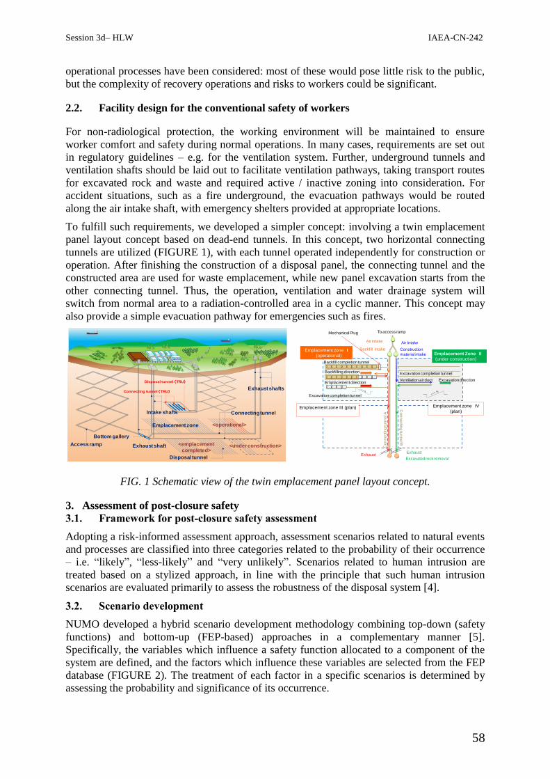
Session 3d– HLW IAEA-CN-242
58
operational processes have been considered: most of these would pose little risk to the public,
but the complexity of recovery operations and risks to workers could be significant.
2.2. Facility design for the conventional safety of workers
For non-radiological protection, the working environment will be maintained to ensure
worker comfort and safety during normal operations. In many cases, requirements are set out
in regulatory guidelines – e.g. for the ventilation system. Further, underground tunnels and
ventilation shafts should be laid out to facilitate ventilation pathways, taking transport routes
for excavated rock and waste and required active / inactive zoning into consideration. For
accident situations, such as a fire underground, the evacuation pathways would be routed
along the air intake shaft, with emergency shelters provided at appropriate locations.
To fulfill such requirements, we developed a simpler concept: involving a twin emplacement
panel layout concept based on dead-end tunnels. In this concept, two horizontal connecting
tunnels are utilized (FIGURE 1), with each tunnel operated independently for construction or
operation. After finishing the construction of a disposal panel, the connecting tunnel and the
constructed area are used for waste emplacement, while new panel excavation starts from the
other connecting tunnel. Thus, the operation, ventilation and water drainage system will
switch from normal area to a radiation-controlled area in a cyclic manner. This concept may
also provide a simple evacuation pathway for emergencies such as fires.
FIG. 1 Schematic view of the twin emplacement panel layout concept.
3. Assessment of post-closure safety
3.1. Framework for post-closure safety assessment
Adopting a risk-informed assessment approach, assessment scenarios related to natural events
and processes are classified into three categories related to the probability of their occurrence
– i.e. “likely”, “less-likely” and “very unlikely”. Scenarios related to human intrusion are
treated based on a stylized approach, in line with the principle that such human intrusion
scenarios are evaluated primarily to assess the robustness of the disposal system [4].
3.2. Scenario development
NUMO developed a hybrid scenario development methodology combining top-down (safety
functions) and bottom-up (FEP-based) approaches in a complementary manner [5].
Specifically, the variables which influence a safety function allocated to a component of the
system are defined, and the factors which influence these variables are selected from the FEP
database (FIGURE 2). The treatment of each factor in a specific scenarios is determined by
assessing the probability and significance of its occurrence.
<under construction>Access ramp
Exhaust shafts
Bottom gallery
Disposal tunnel
<operational>
Connecting tunnelIntake shafts
Exhaust shaft
Emplacement zone
Disposal tunnel (TRU)
Connecting tunnel (TRU)
<emplacement
completed>
Emplacement direction
Excavation completion tunnel
Co
nn
ectin
g tu
nn
el A
Emplacement zone I
(operational)
Emplacement zone III (plan) Emplacement zone IV
(plan)
Co
nn
ectin
g tu
nn
el B
Excavation direction
Backfilling direction
Backfill completion tunnel
Mechanical Plug To access ramp
Ventilation air duct
Air Intake
Construction
material intake
Excavated rock removal
Exhaust
Excavation completion tunnel
Exhaust
Air intake
Backfill intakeEmplacement Zone II
(under construction)

Session 3d– HLW IAEA-CN-242
59
FIG. 2 A fishbone diagram which shows the relationship between a safety function and
influencing factors.
3.3. 3.3 Modelling of radionuclide migration
The safety analysis methodology has been improved to reflect the characteristics of site and
repository design as faithfully as possible. In particular, a radionuclide migration model for
the “near-field scale” (≈ several hundred metres) has been developed based on a three-
dimensional mass transport analysis that represents key characteristics of the site and the
associated repository design. 3-D solute transport pathways are evaluated by a particle
tracking method. The various calculation cases for the safety assessment scenarios should be
carried out flexibly and efficiently, so radionuclide migration analysis taking account of
retardation processes is conducted by using 1-D model. To better represent the case
examined, the 1-D radionuclide model is fit to the solute transport properties obtained through
3-D particle tracking to create a 1-D multi-channel model.
4. Summary
The pre- and post-closure safety cases were demonstrated. The R&D will be continued to
improve the confidence in Japan throughout the siting and development of repository.
REFERENCES
[1] Japan Nuclear Cycle Development Institute, H12: Project to establish the scientific and
technical basis for HLW disposal in Japan, JNC-TN1410-2000-003, (2000).
[2] Ministry of Economy, Trade and Industries: Policy of the Final Disposal of Designated
Radioactive Waste (Cabinet Decision on May 22, 2015) (In Japanese), (2015).
[3] Nuclear Regulation Authority, The new regulatory guideline for the HLW storage, (2013).
[4] ICRP, Radiological Protection in Geological Disposal of Long-lived Solid Radioactive
Waste, ICRP Publication 122, Ann. ICRP 42 (3), (2013).
[5] Kurosawa, S., et al., Advances in scenario development for a deep geological repository in
Japan, Proceedings of Global 2015, Paris, September 20-24 (2015).
Safety function of certain component
State variable 1 State variable 2
State variable 3
・・・ ・・
・
Influencing factor 1-1
Influencing factor 1-2
Influencing factor 2-1
Influencing factor 2-2
Influencing factor 3-1
FEP Database
Top Down

Session 3d– HLW IAEA-CN-242
60
03d – 13 / ID 96. Disposal of High Low Level Waste
RESEARCH, DEVELOPMENT AND DEMONSTRATION PROJECTS AT THE JOSEF
UNDERGROUND LABORATORY
J. Stastka, J. Pacovsky
Czech Technical University in Prague, Prague, Czech Republic
E-mail contact of main author: [email protected]
Abstract. The Centre of Experimental Geotechnics (CEG), the department of the Faculty of Civil
Engineering, Czech Technical University in Prague, is a full member of the Underground Research Facility
Network for Geological Disposal (IAEA, URF Network). The main role of the URF Network is to establish a
community for sharing experience and learning in the field of the geological disposal of radioactive waste. The
CEG operates the Josef Underground Laboratory, and the extensive underground laboratory space available at
this facility provides a unique background for experimental research, education, training and demonstration
activities relating to the geological disposal of radioactive waste. Although the Josef facility is not intended for
waste disposal, it does play a very important role in terms of the early stage of the site selection process for the
Czech deep geological repository.
The Expert Cooperation in the Construction of the first Czech Underground Migration Laboratory with the
Potential Application of Active Tracers project makes up one of the most important research projects currently
underway at the Josef facility. The objective is to obtain the knowledge from foreign partners necessary for
putting the first in-situ underground laboratory with the potential application of active tracers into operation in
the Czech Republic. As such research has not yet been conducted in the Czech Republic, it was essential to
engage the involvement of foreign specialists. The participation of Swiss experts from the NAGRA organisation
allows both the design and subsequent implementation of the experimental programme at the Josef facility’s
laboratories in such a way that the research and training processes are effective and so as to avoid the repetition
of outdated experimental procedures and research topics. The ongoing Mock-up Josef experiment, which
consists of an in-situ physical model simulating the vertical emplacement of a container with spent nuclear fuel,
provides a further example of one of the more important experiments underway at the facility. The in-situ
experiment involves research into the effects of heat and groundwater on the bentonite buffer surrounding a
heater which simulates a spent nuclear fuel container emplaced in an underground repository.
This article provides information on the Josef Underground Laboratory and its rich history of RD & D projects
concerning the development of the Czech deep geological repository.
Key Words: Josef Underground Laboratory, geological disposal, migration laboratory,
Mock-up Josef
1. Introduction
The Centre of Experimental Geotechnics (CEG) represents one of the most unique
departments at the Faculty of Civil Engineering, CTU in Prague. In addition to providing
teaching courses, mainly of a practical nature, in the field of geotechnics, it also specialises in
the conducting of complex RD&D projects. One of the research facility’s most important
roles is to provide practical in-situ instruction in the fields of geotechnical engineering,
geology, geochemistry, radiochemistry and radioecology. The training of future experts in this
authentic underground setting also frequently involves the participation of other Czech
universities and experienced specialists from outside the academic sphere. The IAEA
(International Atomic Energy Agency) has added the CEG to its prestigious list of
international training centres. In addition to teaching and training, the CEG is heavily
involved in a wide range of research and development activities; indeed, the Josef
Underground Laboratory, operated by the CEG, is currently being used for research purposes

Session 3d– HLW IAEA-CN-242
61
in connection with a number of European Union-supported international experimental
projects addressing a wide range of issues related to deep repository radioactive waste
disposal (TIMODAZ - FP6, FORGE - FP7, PETRUS II - FP7, DOPAS, etc.) as well as
several domestic projects (Mock-up Josef, etc.) supported by the Czech Ministry of Industry
and Trade, the Czech Science Foundation and the Czech Radioactive Waste Repository
Authority (SURAO).
2. Research, Development and Demonstration Projects
The Josef Underground Laboratory offers more than 5km of a total of 8km of galleries
(driven during the investigation of the Mokrsko – Čelina gold deposits in the period 1981 –
1993) for teaching and research purposes. No less than seven international and domestic
research projects are currently underway at the Josef facility and a further four projects are in
the preparation stage. Whilst the CEG is gradually extending the range of research and
educational activities into other scientific fields, the main theme of both research projects and
educational courses involves issues concerning the safe disposal of spent nuclear fuel in deep
geological repositories including research into migration processes underway in real rock
environments currently being conducted by the CEG in cooperation principally with the
Nuclear Research Institute - Řež (ÚJV Řež), but also including a number of other partner
institutions.
Since the first section (Čelina West) of the Josef underground complex of galleries, with a
total length of 650m (Fig. 1), was opened for educational and research purposes in 2007, the
total length of reconstructed galleries has been gradually extended to over 5km (Čelina West,
Čelina East and Mokrsko West). The granitic rock complex (the Mokrsko West section) has
been equipped with core-forced air ventilation, a power distribution network, water supply
systems and a high-speed internet optical cable network. The various core distribution
systems installed at the facility will serve for the connection of the niche selected for the
construction of the migration laboratory for research involving the application of active
tracers.
In 2010, the first student laboratory for teaching in the field of the disposal of hazardous
substances and gases was constructed in the granitic rock medium section of the underground
complex. In 2013, the CEG FCE CTU opened a migration laboratory for research involving
non-active tracers in the Čelina West underground section (in the vicinity of the entry portals
to the underground complex). The migration laboratory was built as part of the TA CR
Determination of the Migration Parameters of Minerals with Fissure Permeability using
Fluorescent Solutions project. Clearly, therefore, the CEG has extensive experience in terms
of the reconstruction of underground galleries for the needs of specialised laboratories.
In 2011, the CEG opened a new facility within the Josef complex – the Josef Regional
Underground Research Centre (Josef URC) which involved the complete reconstruction of a
surface building to include an experimental hall, laboratories and other support facilities. This
building provides the necessary backup services for the experimental research conducted in
the underground complex.

Session 3d– HLW IAEA-CN-242
62
FIG 1. – Horizontal layout of the Josef Underground Laboratory (left) and pictures of the entrance to
the underground complex; the upper-right picture shows the entrance to the underground complex
prior to reconstruction in 2006; the lower-right picture shows the entrance portals today
At the beginning of 2013, the CEG submitted the Inter University Laboratory for the In-situ
Teaching of Transport Processes in a Real Rock Environment development project for
approval to the Ministry of Education, Youth and Sport of the Czech Republic; the co-
researcher consists of ICT Prague.
In December 2013, together with a number of research partners (with ÚJV Řež as the senior
researcher), the CEG applied to the Technology Agency of the Czech Republic (TA CR) to
conduct the PAMIRE project (Transfer of Granitic Rock Parameters from the Micro Scale to
the Real Rock Massif Scale).
However, since neither of the above projects provide for financial support for the participation
of foreign experts, the CEG subsequently decided to apply for a grant from the Partnership
Fund of the Swiss-Czech cooperation programme. Consequently, a new project entitled
Expert Cooperation in the Construction of the first Czech Underground Migration Laboratory
with the Potential for the Application of Active Tracers commenced in 2014. Up to this time,
research into migration processes in the real environment of an underground laboratory using
active tracers was allowed at just two other European facilities – SKB, Sweden and NAGRA,
Switzerland. Importantly, the CEG (and ÚJV Řež) has enjoyed extensive cooperation with
both these facilities in the past in the context of the EU FP6 and FP7 (Euratom) research
projects. It is generally recognised that the Swiss organisation NAGRA, which runs the
Grimsel Test Site (GTS) underground laboratory, employs the most experienced experts in
the field of migration research. Therefore, the objective of the project, which will include
consultation with Swiss experts, mutual visits and a series of bilateral workshops, is to obtain
the knowledge necessary for putting into operation the Czech Republic’s first in-situ
underground laboratory with the potential for the application of active tracers.
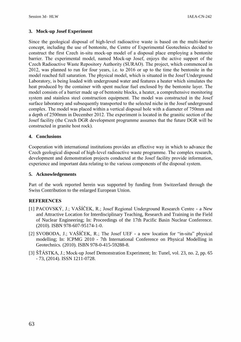
Session 3d– HLW IAEA-CN-242
63
3. Mock-up Josef Experiment
Since the geological disposal of high-level radioactive waste is based on the multi-barrier
concept, including the use of bentonite, the Centre of Experimental Geotechnics decided to
construct the first Czech in-situ mock-up model of a disposal place employing a bentonite
barrier. The experimental model, named Mock-up Josef, enjoys the active support of the
Czech Radioactive Waste Repository Authority (SURAO). The project, which commenced in
2012, was planned to run for four years, i.e. to 2016 or up to the time the bentonite in the
model reached full saturation. The physical model, which is situated in the Josef Underground
Laboratory, is being loaded with underground water and features a heater which simulates the
heat produced by the container with spent nuclear fuel enclosed by the bentonite layer. The
model consists of a barrier made up of bentonite blocks, a heater, a comprehensive monitoring
system and stainless steel construction equipment. The model was constructed in the Josef
surface laboratory and subsequently transported to the selected niche in the Josef underground
complex. The model was placed within a vertical disposal hole with a diameter of 750mm and
a depth of 2500mm in December 2012. The experiment is located in the granitic section of the
Josef facility (the Czech DGR development programme assumes that the future DGR will be
constructed in granite host rock).
4. Conclusions
Cooperation with international institutions provides an effective way in which to advance the
Czech geological disposal of high-level radioactive waste programme. The complex research,
development and demonstration projects conducted at the Josef facility provide information,
experience and important data relating to the various components of the disposal system.
5. Acknowledgements
Part of the work reported herein was supported by funding from Switzerland through the
Swiss Contribution to the enlarged European Union.
REFERENCES
[1] PACOVSKÝ, J.; VAŠÍČEK, R.; Josef Regional Underground Research Centre - a New
and Attractive Location for Interdisciplinary Teaching, Research and Training in the Field
of Nuclear Engineering; In: Proceedings of the 17th Pacific Basin Nuclear Conference.
(2010). ISBN 978-607-95174-1-0.
[2] SVOBODA, J.; VAŠÍČEK, R.; The Josef UEF - a new location for “in-situ” physical
modelling; In: ICPMG 2010 - 7th International Conference on Physical Modelling in
Geotechnics. (2010). ISBN 978-0-415-59288-8.
[3] ŠŤÁSTKA, J.; Mock-up Josef Demonstration Experiment; In: Tunel, vol. 23, no. 2, pp. 65
- 73, (2014). ISSN 1211-0728.

Session 3d– HLW IAEA-CN-242
64
03d – 14 / ID 125. Disposal of High Level Waste
THE MANAGEMENT OF USED (SPENT) FUEL AND HIGH LEVEL WASTE IN
SOUTH AFRICA V Maree
1, A Carolissen
2
1National Nuclear Regulator (NNR), Cape Town, South Africa
2 National Radioactive Waste Disposal Institute (NRWDI), Pretoria, South Africa
E-mail contact of main author: [email protected]
Abstract. As a country with a nuclear power program and radioisotope production facility, the Republic of
South Africa (RSA) generates Used Nuclear Fuel (UNF) and radioactive waste through numerous activities. The
cornerstone of South Africa’s approach to addressing radioactive waste management is the Radioactive Waste
Management Policy and Strategy for the Republic of South Africa. The Policy and Strategy serves as a national
commitment to address radioactive waste management in a coordinated and cooperative manner and represents a
comprehensive radioactive waste governance framework by formulating, in addition to nuclear and other
applicable legislation, a policy and implementation strategy developed in consultation with all stakeholders. In
accordance with the Policy and Strategy, final disposal is regarded as the ultimate step in the radioactive waste
management process, although a stepwise waste management process is acceptable. Long-term storage of
specific types of waste, such as High-Level Waste (HLW), long-lived waste and high activity disused
radioactive sources, may be regarded as one of the steps in the management process. This poster presents the
South African National Radioactive Waste Management Model with a description of: the radioactive waste
management governance framework; the current HLW and UNF management, the management option and UNF
strategies. Also the poster addresses consideration of the lessons learnt from the Fukushima accident and its
impact on future radioactive waste management strategies and options, plans related to possible long term
operation of the existing nuclear power plants, introduction of new nuclear power plants and public acceptance
and challenges from anti-nuclear groups.
Key Words: Used Nuclear Fuel; High Level Waste; South Africa’s Management Strategies;
Challenges.
1. Introduction
The Republic of South Africa (RSA) recognizes the importance of the safe management of
spent fuel and radioactive waste, for this reason the country is a contracting party to the
International Atomic Energy Agency (IAEA) Joint Convention on the Safety of Spent
Nuclear Fuel Management and Safety of Radioactive Waste Management [1]. The Joint
Convention provides for the establishment and maintenance of a legislative and regulatory
framework to govern the safety of spent fuel and radioactive waste management. South Africa
fulfills its obligations under the Joint Convention by the establishment of a Radioactive Waste
Management Policy and Strategy for the Republic of South Africa (RWMP&S) [2] and has
invited the IAEA to conduct the Integrated Nuclear Infrastructure Review (INIR) mission in
2013. The INIR mission has recommended that South Africa develop an integrated national
Nuclear Fuel Cycle strategy, including Used Nuclear Fuel (UNF)/High Level Waste (HLW)
disposal [3]. South Africa already has in place a strong national radioactive waste
management model and is considering different options and strategies to address the long
term management of the UNF and HLW as recommended by the INIR.
2. Background
The past strategic programs and the current nuclear programs contribute to the generation of
HLW and UNF. HLW for legal and regulatory purposes, is defined as ‘waste with levels of

Session 3d– HLW IAEA-CN-242
65
activity concentration high enough to generate significant quantities of heat (>2kW/m3), or
waste with large amounts of long lived radionuclides’.
In 1991, South Africa signed the Nuclear Non-Proliferation Treaty and in 1993 voluntarily
announced the dismantling of its nuclear weapons programme, HLW was generated. In the
South African context, HLW doesn’t include fuel coming from the irradiated fuel reactor
cycle. The term “used fuel” is used instead of “spent fuel” because used fuel is considered to
have useful material and is not classified as radioactive waste. UNF is produced in two main
nuclear facilities: The South African Nuclear Energy Corporation (Necsa) and Koeberg
Nuclear Power Station (KNPS). Necsa, located at Pelindaba 30 km west of Pretoria operates a
20 Megawatt tank-in-pool type nuclear research reactor: SAFARI-1 (Fig.2.). The research
reactor has been in operation for 50 years and is used in the production of medical
radioisotopes and nuclear research. KNPS is the only nuclear power plant in Africa and is
comprised of 2 Framatome PWR reactors of 900 Mwe each operated by the State Own
Company Eskom. KNPS is in operation since 1984 and situated on the Atlantic coast 40
kilometers north of Cape Town (Fig.2.).
3. South African Radioactive Waste Management Model
The overarching objective of radioactive waste management is to deal with radioactive waste
in a manner that protects human health and the environment now and in the future without
imposing undue burdens on future generations.
3.1.Radioactive Waste Management Governance Framework
The following diagram depicts the Governance Framework for radioactive waste in RSA:
Fig.1. Schematic Governance Framework for Radioactive Waste Management.
It is imperative to note that the legislative and regulatory framework for radioactive waste
management and disposal is informed by and gives effect to:
Joint Convention on the Safety of Spent Fuel Management and on the Safety of
Radioactive Waste Management [1];
National Radioactive Waste Disposal Institute Act (NRWDIA) [4];
Nuclear Energy Act [5];
RWMP&S.

Session 3d– HLW IAEA-CN-242
66
In order to ensure that radioactive wastes are managed safely, the governance framework
makes provision for: an established legislative and regulatory framework, the necessary
organisations for implementation and providing oversight of waste management operations
and facility development. Independence between the Regulator, Waste Generators and
repository operator is the key to ensure that the RSA has an integrated and sustainable
approach to ensure that the long term management is executed. RSA’s approach to addressing
radioactive waste management issues is RWMP&S which sets a general policy for dealing
with all radioactive waste from the nuclear fuel cycle. RWMP&S developed in consultation
with all stakeholders and transparency’s principle serves as a national commitment to address
radioactive waste management. RWMP&S puts forward the following hierarchy of waste
management options to be followed, where practicable: avoiding waste and minimisation;
reuse, reprocessing and recycling; storage; conditioning and final disposal. Final disposal is
regarded as the ultimate step in the radioactive waste management process.
The RWMP&S establishes the National Committee on Radioactive Waste Management
(NCRWM). This committee is constituted by representatives from different organs of state.
One of the committee responsibilities is to evaluate the radioactive waste plans submitted by
radioactive waste generators and to provide recommendations to the Minister of Energy.
The RWMP&S also makes provision for a National Radioactive Waste Management Fund
managed by the South African Government to ensure sufficient provision for the long term
management of radioactive waste with the principle that the ‘Polluter pays’.
The NRWDIA became effective in December 2009. The NRWDIA endorsed the
establishment of the National Radioactive Waste Disposal Institute (NRWDI) which is a
national public entity. The Institute is mandated to discharge a Ministerial institutional
obligation with respect to the management of radioactive waste disposal and related waste.
The RSA acceded to the Joint Convention on the Safety of Spent Fuel Management and on
the Safety of Radioactive Waste Management (Joint Convention) in 2006. One of the objects
of the NRWDI is to fulfil national obligations in respect of the long term management of
radioactive waste disposal and related waste management activities as dictated by the Joint
Convention.
According to Section 5 of NRWDIA, the Institute must, inter alia, —
(a) perform any function that may be assigned to it by the Minister in terms of Section 55(2)
of the Nuclear Energy Act, in relation to radioactive waste disposal;
(e) manage, operate and monitor operational radioactive waste disposal facilities, including
related storage and predisposal management of radioactive waste at disposal sites;
(g) investigate the need for any new radioactive waste disposal facilities and site, design and
construct such new facilities as may be required;
(h) conduct research and develop plans for the long-term management of radioactive waste
storage and disposal.
3.2.The Current HLW and UNF Management
At present nuclear installations in South Africa use a combination of wet and dry storage for
used nuclear fuel. UNF from the KNPS is currently stored in pools on the site as well as in
casks designed and constructed for storage of used nuclear fuel. The used nuclear fuel from
the SAFARI-1 Research Reactor is initially stored in the reactor pool for at least two years to
facilitate cooling of the used fuel prior to it being transferred to an authorised dry storage
facility on the Pelindaba site. Some HLW is stored on the same site.

Session 3d– HLW IAEA-CN-242
67
3.3.The Management Option and Strategies for HLW and UNF
The RWMS&P clearly indicates that storage on these sites is not sustainable in the long term
and considers the following waste management options for UNF and HLW: long-term above
ground storage on an off-site licensed facility; reprocessing, conditioning and recycling; direct
deep geological disposal and transmutation. Regardless of any UNF/HLW management
strategy chosen, a Centralized Interim long term off-site Storage Facility (CISF) and Deep
Geological Repository (DGR) for final disposal will be required. Like any option chosen for
the UNF, the DGR needs to be technically sound, socially acceptable, environmentally
responsible and economically feasible. Transmutation requires major investment, two cycles
options for the management of UNF can be considered: open cycle and closed cycle.
Open cycle without recycling/ reprocessing:
The fuel will be stored at the reactor site and will be transferred to a centralised off-site
storage pending the final decision or, after the transfer to a centralised off-site storage, the
UNF will be directly disposed.
Closed cycle with recycling/ reprocessing:
Firstly, the UNF will be stored at the reactor site for a specific period, secondly will be
reprocessed and finally the UNF will be disposed or, after the transfer to a centralised off-site
storage, the UNF will be reprocessed were the useful material will be reused and the waste
will be disposed.
Currently the solid low level and intermediate level waste from KNPS and Necsa are disposed
of at the national radioactive waste disposal facility Vaalputs located in the Northern Cape
Province (Fig.2.). Preliminary investigation in the early 90s has indicated that Vaalputs has
suitable characteristics that would make this site a favourite candidate to host the CISF and a
DGR.
FIG. 2. Geographical location of selected nuclear facilities.
The RSA has addressed the INIR mission’s recommendation by drafting a new policy
detailing options and strategies for UNF/ HLW management. The document was finalized and
in currently under review by the Cabinet of the RSA.
4. Key Challenges
One of the lessons learnt from the Fukushima accident was the importance to limit the UNF
inventory on-site. On-site storage should only be for cooling purposes of the UNF. The RSA
Government has committed to establish and operate a centralized off-site interim storage

Session 3d– HLW IAEA-CN-242
68
facility by 2025 and a deep geological repository by 2065 [6]. In addition, centralized off-site
interim storage facility will provide South Africa with the flexibility to make an informed
decision with regard to fuel cycle strategy (open or closed) Provision must be made for
additional waste storage/ disposal due to potential operation of new nuclear power plants as
the RSA is considering a new nuclear build programme and the possible long term operation
of the KNPS. The Fukushima accident has eroded the confidence of the public in nuclear
power and safe radioactive waste management. Hence, to be successful the waste
management programme must overcome this negative perception as technical competence is
not enough to ensure and instill stakeholder trust and acceptability. Waste Generators in RSA
must still submit their radioactive waste management plans for review and to the NCRWM.
This committee will determine the funding strategy and requirements for sustainable long
term operation of NRWDI. Funding is required for disposal activities, research and
development including investigations into waste management/disposal options. The process
of the site’s selection for the centralized off-site interim storage facility and deep geological
repository must be developed for licensing.
5. Conclusion
South Africa has an integrated and extensive national radioactive waste management model
which considers the different options and strategies to address the long term management of
the UNF and HLW as recommended by the INIR. Final disposal is regarded as the ultimate
step in the radioactive waste management process. In spite of challenges and irrespective of
the fuel strategy chosen, it is inescapable that South Africa needs the following waste
management infrastructure namely (i) CISF and (ii) a DGR. Finally, the RSA must develop
and implement a comprehensive communication strategy and plan to demystify and decipher
the public’s fears regarding the management of radioactive waste and to deepen and
strengthen stakeholder acceptance, confidence and trust.
REFERENCES
[1] Joint Convention on the Safety of Spent Fuel Management and on the Safety of
Radioactive Waste Management (IAEA, 1997).
[2] Radioactive Waste Management Policy and Strategy for the Republic of South Africa
(2005).
[3] Department of Energy, Media Statement: Nuclear Procurement Process Update, 14 July
2015.
[4] National Radioactive Waste Disposal Institute Act (NRWDIA), Act 53 of 2008.
[5] Nuclear Energy Act, 1999, (Act No. 46 of 1999).
[6] South African National Report on the Compliance to Obligations under the Joint
Convention on Safety of Spent Fuel Management and on the Safety of Radioactive Waste
Management, September 2014.

Session 3d– HLW IAEA-CN-242
69
03d – 15 / ID 140. Disposal of High Level Waste
REGULATORY EXPERIENCES IN REVIEWING CONSTRUCTION LICENSE
APPLICATION FOR THE DISPOSAL OF SPENT NUCLEAR FUEL IN FINLAND
J. Leino
Radiation and Nuclear Safety Authority, STUK, Helsinki, Finland
E-mail contact of main author: [email protected]
Abstract. Finland is one of the first countries in the world in developing a disposal solution for spent nuclear
fuel (SNF). The Construction License Application (CLA) for the Olkiluoto SNF encapsulation and disposal
facility was submitted by Posiva, the implementer, to the authorities at the end of 2012 and the Government
granted construction license in November 2015. The post-closure safety case submitted as part of the CLA was
reviewed during 2013-2015. The CLA covered both operational safety (PSAR) and post-closure safety.
In this paper, experiences gathered during the review process post-closure safety case are discussed. During the
review process some practices proved to be good but the process revealed also some needs for improvements for
the next licensing phase.
Key Words: nuclear waste, spent nuclear fuel, disposal, review of post-closure safety case.
1. Introduction
The safety case submitted as a part of the CLA was reviewed during 2013 - 2015. The safety
case covered both operational safety (PSAR) and post-closure safety documentation. The
actual review process consisted of three phases: the initial phase, detailed review and
assessment phase, and then the finalizing phase. The last phase consisted of preparation of
conclusions, writing and finalization of statements, decisions and review reports.
During the pre-licensing phase STUK started the work aiming to the readiness to review the
construction license application. STUK also increased the own competence and resources to
be prepared for the review. A strategic resource plan was made and the amount of people
working mainly for the waste management was increased. STUK made also framework
contract with 13 external experts to support STUK during the review of post-closure safety
case.
2. Regulatory experiences during pre-licensing phase
In the pre-licensing phase before the actual review phase STUK assessed Posiva’s R&D work
and draft documentation, planned the actual review process and increased its’ regulatory
resources and competence. While assessing Posiva’s R&D work and draft documentation
STUK created a list of key safety concerns and had an active communication with Posiva.
Active communication consisted of giving feedback to Posiva, discussions concerning the
content and structure of the safety case, expressing regulatory expectations, hearing of
Posiva’s expectations and forming of common understanding of the regulatory requirements.
The regulatory assessment of safety is, of course, done against regulatory safety requirements
i.e. the government decree and regulatory guidance (STUK YVL guides). In this phase
STUK’s approach was initially safety issue oriented and bottom- up assessment. This was
partly because of the regulatory safety requirements were not detailed enough. Thus, STUK
started to develop a more structured review and assessment process for the safety case review

Session 3d– HLW IAEA-CN-242
70
and prepared a so called review plan that would be a strong basis for the review and would
guide the review. The review plan changed STUK’s approach to more regulatory requirement
oriented and safety related review basis. The review plan was seen necessary since it was
acknowledged that addressing single technical concerns in many cases did not lead to better
overall understanding of safety and often the linkage to safety was not very clear thus the
review plan collects earlier regulatory observations and expectations for the safety case.
Regulatory safety requirements given in the government decree on the safety of disposal of
nuclear waste and regulatory guides were linked to these observations and expectations. The
review plan was used as guidance both for internal and external experts participating in the
review of the safety case. It also formed a basic structure for STUK’s safety evaluation
reports for operational and post-closure safety.
3. Regulatory experiences during initial review phase
In the initial review phase STUK performed the completeness review of the safety case during
the first three months. The aim of this phase was to verify that the safety case contained all
main elements requested by the YVL guides. The conclusion from this completeness review
was that Posiva had delivered most of the documentation required and STUK could continue
the review despite some missing parts of the safety case. Nevertheless, STUK requested
Posiva to deliver the missing parts of the documentation to STUK and to update some parts of
the documentation which were considered to be too general. Based on the completeness
review observations, STUK made several requests for additional information because of the
adequacy and the quality of the safety case documentation. The extent and structure of the
post-closure safety case documentation were such that it was challenging to check the
adequacy and the quality of the elements during the initial review phase.
However, this kind of completeness review proved to be useful tool to identify the
completeness of the safety case. It also helped to identify any shortcomings and allowed
STUK to continue its review and move on to the detailed review phase on areas that were
found to be complete.
4. Regulatory experiences during detailed review phase
The detailed review phase took place three to four months after the initial review phase
depending on the documentation. The review plan which facilitated the review process of post
closure safety documentation can be considered as a good practice. The review plan that
STUK developed beforehand was seen as a strong basis for the review of CLA. Although, in
the last phase of the review it was identified that even more detailed review guidance was
needed in the next licensing phase. The more detailed guidance or review plan should consist
of guidance on how to review and assess all the elements collected in the review plan, and
elements of setting up the level of adequacy and also what are the most important and safety
significant parts in the documentation i.e. to what issues the review should be concentrating.
In the detailed review STUK did have difficulties to assess the post-closure safety regarding
some of the elements in the safety case because of the extent and structure of the safety case
and also explicit safety argumentation that was partly missing in the safety case. This was
seen understandable due the uniqueness and first-of-a-kind post-closure safety case
concerning disposal of spent nuclear fuel in Finland. Furthermore, because of missing of
some key parts in the documentation those were noticed in the completeness review the
detailed review of these parts of the documentation was delayed.

Session 3d– HLW IAEA-CN-242
71
The explicit safety argumentation has been intrinsic value and has long tradition and lot of
experience in the nuclear reactor safety assessments. Similar explicit safety argumentation
and precise minimum content and structure of the safety case that have been agreed before
hand between the regulator and the license applicant should be introduced to the nuclear
waste post-closure safety cases also. That would make post-closure safety case easier to
review for the regulator and increase traceability and transparency.
STUK decided to reform the regulatory guidance for nuclear facilities in 2005. The new
guidance was planned to be published well before Posiva was going to submit the CLA.
Publication was postponed because of delays in the project and Fukushima accident and thus
the new YVL guides were released after the submittal of the CLA. Despite of this, CLA was
written based on the new guidance. This was possible because STUK agreed with Posiva that
Posiva would use final draft versions of the guidance for the CLA documentation. A few late
changes in the guidance caused some challenges for the license applicant to prepare the
documentation as well as for STUK for the reviewing it. Thus it can be concluded that the
guidance should be ready for use for the license applicant well in advance before the
submission of the license application and any major changes in the guidance should not be
done during the review but afterwards. As a whole it was considered important that the CLA
was reviewed against the latest regulations. It should be also clear that there is a mutual
understanding between the regulator and the license applicant concerning the requirements.
During the detailed review phase STUK made approximately 30 requests for additional
information in areas where further information or clarification was needed. Requests for
additional information concerned mainly main documents e.g. PSAR and post-closure safety
case. As a result of the detailed review phase STUK accepted main documents e.g. PSAR and
post-closure safety case and submitted statement and safety evaluation report [1] to the
Government. STUK’s main conclusion was that encapsulation plant and disposal facility can
be built to be safe. Also there is a sufficient reliability that there will be no detrimental
radiation effects to the public or environment neither during the operational period nor after
decommissioning and closure of the facility.
In the statement to the government STUK raised areas that need further development before
specific construction step or before submittal of operating license application. These areas are
related for example to process for selecting suitable disposal tunnel location, further R&D and
assessment of engineered barrier system performance and development in post-closure
scenario analysis and presentation of post-closure safety case. These areas have been further
specified in PSAR and post-closure safety case decisions [2, 3] that STUK has send directly
to Posiva. Raising these areas in the statement and decisions STUK created more steps to
already step-wise licensing process. This is justified due the uniqueness and first-of-a-kind
nature of this kind of nuclear waste disposal concept.
5. Conclusions
A well planned preparation for the review during pre-licensing phase is a key factor to a
successful review. Plan for the review should be prepared and resources assured before the
review. The review should be guided as detailed as possible.
Completeness review before the detailed review phase outlines the scope of the safety case
and identifies the shortcomings in it.
The review process revealed that more thorough discussions between the regulator and the
license applicant before the review would have been needed. Especially more thorough
discussions concerning the structure of the documentation and the level of details would have

Session 3d– HLW IAEA-CN-242
72
simplified and facilitated the review process. Regulations that are up to date are of importance
for this kind of new nuclear waste disposal concept. Also discussions concerning the mutual
understanding on the regulatory guidance are essential for avoidance of any
misunderstandings between the regulator and the license applicant. However, despite the
appeared challenges the review could be concluded because of the active communication with
the implementer during the review phase. Lessons learned during the review process have
been analyzed and development of review practices and safety guidance have been started.
REFERENCES
[1] STUK, STUK’s statement and safety assessment on the construction of the Olkiluoto
encapsulation plan and disposal facility for spent nuclear fuel, STUK-B 196, Helsinki
2015.
[2] STUK, STUK’s decision on the PSAR of the encapsulation plant and disposal facility for
spent nuclear fuel (in Finnish), 10.2.2015, Helsinki.
[3] STUK, STUK’s review on the construction license stage post closure safety case of the
spent nuclear fuel disposal in Olkiluoto, STUK-B 197, Helsinki 2015.

Session 3d– HLW IAEA-CN-242
73
03d – 16 / ID 155. Disposal of High Level Waste
GENERIC UNDERGROUND RESEARCH FACILITY IN THE MIDDLE STAGE OF
THE SITE SELECTION PROCESS: BUKOV URF, CZECH REPUBLIC
L. Vondrovic, I. Pospíšková, J. Augusta, J. Slovák, A. Vokál
Radioactive Waste Repository Authority
E-mail contact of main author: [email protected]
Abstract. The Czech Republic’s radioactive waste disposal concept assumes the construction of a deep
geological repository in crystalline host rocks (granitic and metamorphic) at a depth of 500m below the earth’s
surface. The current stage of the site selection and evaluation process requires that the characteristics of the
geosphere be determined at a depth envisaged for the future repository. This abstract addresses the current state
of construction and preparation of the R&D programme for the new Bukov generic underground research
facility. This facility will, over the next 10 years or so, provide invaluable support for the current siting process
and the safety evaluation of the disposal concept in the Czech Republic by providing the depth calibration
parameters required to supplement the data acquired from surface exploration. The Bukov URF (located within
the Rožná uranium mine complex) is located at a depth of 600m in metamorphic rocks in the proximity of a
potential site for the construction of the future DGR. The laboratory itself is currently approaching the end of the
construction phase which commenced in 2013. The intensive characterization programme which was conducted
during the construction phase focused on the characterization of the site from the geological, geomechanical and
hydrogeological aspects. The data set acquired from this initial scientific programme will serve as input data for
the construction of synthetic geosphere models which, in turn, will serve for determining the precise location of
the various experiments and the development of specialised site description methodologies; moreover, it will
provide essential information concerning the design of the future repository. One of the most important parts of
the characterization programme will consist of the long-term monitoring of the geological processes that take
place at repository depth within the Bohemian Massif. The future experimental programme will focus on the
following principal research areas: the geosphere and materials and techniques. It is anticipated that the
geosphere part of the programme will provide a description of the characteristics of rock mass behaviour in
terms of migration properties, fracture connectivity and the long-term stability of the rock mass as well as the
stability of the underground construction itself. The materials part will focus on the long-term stability of the
various materials employed and their degradation rates. Finally, the technology part will provide valuable
information concerning the preparation of individual components of the emplacement system and the support
infrastructure.
Key Words: URF, disposal, experimental programme
1. Introduction
The SURAO generic research programme is focused on the detailed testing of the crystalline
rock concept. Generic laboratories serve as training centres for staff members,
experimentation involving mock-up experiments and the development of methodologies for
the study of rock conditions in underground environments. One of the most important aspects
of generic research consists of the testing of the validity of data collected from the earth’s
surface and the approximation of such data to depths at which the construction of the
repository is envisaged. SURAO has close connections with three underground research
centres in the Czech Republic: the Josef Gallery, the Bedřichov Water Supply Tunnel and the
Bukov Underground Research Facility (Bukov URF). The Bukov underground generic
laboratory is located in the eastern part of the Czech Republic near the Kraví hora candidate
repository site and adjacent to the Rožná uranium mine at a depth of 600m below the earth’s
surface. From the geological point of view the facility is located in the north eastern part of
the Moldanubian Zone of the Variscan orogen and is composed of migmatitised paragneisses

Session 3d– HLW IAEA-CN-242
74
with amphibolite layers. The felsic granulites display the same deformational history as that
of the nearby Kraví hora candidate locality.
FIG. 1. Scheme of URF Bukov
2. Construction
Construction commenced in 2013 with the blasting of the main access tunnel. Following an
intensive drilling campaign (the total length of the boreholes amounted to 500m) two suitable
rock blocks were defined for testing purposes: a consolidated block made up of high quality
rock intended for diffusion and demonstration experiments and slightly fractured rock for the
performance of migration, hydraulic and material tests. The laboratory itself consists of a
300m-long connecting cross gallery with a profile of 9.2m2 leading from the access shaft and
the underground facility itself consisting of a 90m-long large-profile chamber and a gallery
niche system with a total length of 40m (see Fig 1). The second test chamber section consists
of a 20m-long niche in the front part of the access tunnel. Rock bolts will be used to provide
support for the underground sections supplemented with yieldable TH arches in areas
exhibiting more complicated geological conditions. The intensive drilling campaign consisted
of the drilling of a series of exploration boreholes of a total length of 500m into the walls of
the access tunnel for geophysical and hydrogeological monitoring purposes. The conventional
blasting method was used for the excavation of the access tunnel, whereas the smooth blasting
method was applied with respect to the laboratory niches.
3. Characterization phase
The scientific programme conducted during the construction of the facility concentrated on
the characterization of the site from the geological, geomechanical and hydrogeological points
of view. The results will serve as input material for the construction of synthetic geosphere

Session 3d– HLW IAEA-CN-242
75
models which will, in turn, serve for the precise positioning of the various experiments
included in the research programme. The characterization programme will include the
following research areas:
Complex geological characterization
The application of a range of geological methods will be aimed at obtaining a
multidisciplinary description of the host rock in order to assist in determining the optimum
location for the performance of the experimental programme. Geological characterization will
comprise geological and structural mapping and the deciphering of the temporal, spatial and
thermal evolution of the ductile and brittle pattern. Subsequent more detailed characterization
will concentrate on more specialized study fields e.g. the radiometric dating of the fault
system, the evolution of micro-fractures within the rock, etc.
Geotechnical characterization
The geotechnical programme will be made up of three specific areas: (i) stress monitoring, (ii)
geotechnical laboratory testing and (iii) seismic monitoring. The stress measurements will
allow for the prediction of the stability of the rock mass as well as for the determination of
stress changes during the excavation process. Geotechnical testing will comprise a range of
methods that will serve for initial rock mass characterization purposes and for the provision of
input data for further geotechnical modelling. Seismic monitoring will be concerned with the
potential reactivation of the fault system during blasting and the identification of any induced
seismic activity that might occur as a result of local mining operations.
Transport properties of the rocks
The determination of the transport properties of the surrounding rock will serve for the
laboratory testing of radionuclide sorption and migration from a depth at which the
construction of the repository is envisaged.
Hydrogeological properties of the rock mass
An understanding of the behaviour of water within the repository system is crucial in terms of
safety case considerations. Hydrogeological studies therefore include the monitoring of water
influx and the evolution of the chemical and physical properties of water collected from the
surrounding rock. Borehole hydrogeological tests, tracer tests and water pressure tests will be
conducted during the experimental phase.
Synthetic geosphere models
The application of the methods described above will result in the construction of the
following synthetic geosphere models:
3D structural-geological model
3D hydrogeological model
3D geotechnical model
4. Experimental programme
The underground research facility research and experimental (R&E) programme will be
conducted in very similar conditions to those expected at the location of the future deep
geological repository. The Bukov URF will serve as a test site for assessing the behaviour of
the rocks at the candidate sites at a depth matching the expected depth of the deep geological
repository until the final site is selected and the confirmation underground laboratory is built
at that site.
Session 3d– HLW IAEA-CN-242
76
The experimental programme consists of 7 basic areas:
R&E Programme 1: Pilot characterization of the rocks in order to test the methodology for
setting up 3D Geo / GT / HG models of the site
R&E Programme 2: Testing of long-term monitoring methods for processes occurring at
repository depth
R&E Programme 3: Testing of groundwater flow / radionuclide transport models of the
fracture environment of the DGR
R&E Programme 4: Testing of the effect of the rock at repository depth on the properties of
the engineered barriers
R&E Programme 5: Testing of the development of excavation disturbed/damaged zones in
crystalline complex rocks at repository depth
R&E Programme 6: Investigation of the effect of the rock massif on the underground
structures of the DGR
R&E Programme 7: Demonstration experiments
5. Conclusion
The construction of the Bukov Underground Research Facility is fundamental in terms of the
characterization of rock masses in which it is intended that the future Czech radioactive waste
repository will be constructed. The facility is ideally located for this purpose, i.e. it is 600m
beneath the earth’s surface and situated in a crystalline rock environment. The research to be
conducted at the facility will make a significant contribution towards forming a more detailed
understanding of the processes that will take place within the repository over its lifetime.

Session 3d– HLW IAEA-CN-242
77
03d – 17 / ID 161. Disposal of High Level Waste
CIGEO PROJECT:
FROM BASIC DESIGN TO DETAILED DESIGN – PPURSUANT TO REVERSIBILITY
F. Launeau, G. Ouzounian
Andra, French National Radioactive Waste Management Agency, Parc de la Croix Blanche,
92298 Châtenay-Malabry, France
E-mail contact of main author: [email protected]
Abstract. The Cigeo project has been in the works for 25 years. Numerous studies have been conducted, with
further specific research thanks to direct access to the Callovo-Oxfordian clay formation from the underground
laboratory of Bure-Saudron. These studies and research initially aimed to demonstrate the feasibility of the
repository. They also helped gain a high level of understanding of phenomena to support design studies and
demonstrate safety. Transition to the industrial phase began with the development of a plan for delivering waste
to the facility for disposal. The plan introduced sequencing for the various types of waste to be disposed of, and
was optimised to determine the size of inspection, transfer and handling facilities. In describing the life of the
repository and therefore the vision for its operation, it has become obvious that our generation should not impose
choices on future generations. We must provide them with reference technical solutions, with the financial
resources to implement them. It is also our duty to begin the construction and initial operating phases. However,
because the facility will operate over more than 5 generations, we must leave a degree of flexibility so that they
may reassess the options that we define and adopt their own solutions, as necessary. They will also benefit from
operational experience gathered as facility operations develop. This is the context in which the preliminary
design phase was finalised in preparation for the detailed design phase, with the aim of gradual commissioning
during the latter part of the next decade.
1. Introduction
Since the Act of December 1991 concerning research into the management of radioactive
waste, Andra has been conducting the programme for geological disposal in compliance with
the objectives set forth. The initial 15-year phase was mainly dedicated to research, including
research into alternatives to geological disposal. Following the various bids for the creation of
an underground laboratory, in 1998 the French Government selected the Bure-Saudron
facility in the Meuse and Haute-Marne departments of north-eastern France. In 2005, Andra
compiled the results and analysed them in the Dossier 2005 Argile report. The main finding of
Dossier 2005 was that geological disposal is feasible in the clay formation studied (Callovo-
Oxfordian clay) and that its safety could be proven. Based on the various results, French
Parliament passed the Planning Act in 2006, establishing geological disposal as the reference
solution for managing high-level waste (HLW) and intermediate-level long-lived waste (ILW-
LL). The facilities should be planned in a formation previously studied using an underground
laboratory, which indicates the Callovo-Oxfordian near Bure-Saudron. More detailed
investigations therefore focused on this region and in 2009, Andra proposed the location for
underground facilities. Upon completion of a series of assessments and opinions, the French
Government validated the location for the underground repository in March 2010. This began
the industrialisation process for the Cigeo project, followed by a public debate in 2013, which
became useful for later deliberations. When the preliminary design phase was completed and
before beginning the detailed design phase, the life and operation of the disposal facility were
reviewed using updated information to bring a new perspective to the industrial project. Due
to changes to regulatory requirements in France, Cigeo’s detailed design must be used for the
repository construction license application. The construction license application will therefore
Session 3d– HLW IAEA-CN-242
78
be submitted progressively between late 2015 and mid 2018 in agreement with safety
authorities.
9. Development of Cigeo Project
Based on this initial research, Andra proposed an initial project in 2001, which was followed
by a detailed safety assessment. This was submitted for international review and created the
basis for Dossier 2005. The demonstration provided was supported by an understanding of the
phenomena affecting the behaviour of the repository gained from a sustained research effort.
The repository was no longer viewed as a single object placed in the geological environment,
but rather as a group of structures and components developing over time and subject to
relatively complex physical-chemical and sometimes combined phenomena. The approach,
now called Phenomenological Analysis of Repository Situations, has demonstrated an
unparalleled ability to describe repository operation.
Based on this analysis, new developments and improvements to the characteristics of the
structures and components were made. An overall architecture was developed as a working
basis to begin the initial industrial development phases. Once the location of the future
repository was known, more detailed drawings were produced, thus validating the overall
architecture comprising:
Surface nuclear facilities used for receiving, inspecting and conditioning waste, then
transferring packages underground via a funicular;
An approximately 4.2 km long ramp to transfer surface waste packages underground;
A surface mining facility, including access shafts to underground facilities;
An underground facility with a disposal area for ILW-LL, and a disposal area for
high-level vitrified waste.
In 2010, this overview of the main options was confirmed. Based on these main options, the
design phase began, particularly with the preparation of the preliminary design. A first draft
was submitted for public debate in 2013. It was used as the basis for later discussions with
local and regional representatives concerning the location of surface facilities. After public
debate, the location was decided.
Several possible zones were identified directly below surface facilities for mining activities.
Local representatives preferred wooded areas in order to avoid encroaching on farmland. For
nuclear facilities, the planned sector is located directly next to the underground laboratory,
straddling the border between the Meuse and Haute-Marne departments.
3. Launch of the design phase
The technical feasibility of the geological repository relied on simple, robust technical
concepts. Studies and research conducted since have explored avenues for optimisation and
provided more specific details for the basic options in order to develop a preliminary design
for a disposal facility.
The Cigeo geological repository must be able to hold a wide variety of waste packages,
particularly those generated from decades of research and development of industrial
processes. Packages will include cemented intermediate-level waste, bituminised waste, and
packages in various forms with different characteristics. To simplify operations, the various
packages were divided into types for which disposal packages had to be developed. System
standardization has been implemented via use of disposal containers.

Session 3d– HLW IAEA-CN-242
79
The inventory of waste to be disposed of in Cigeo includes 10,000 m3 of vitrified high-level
waste and 70,000 m3 of ILW-LL. The repository is therefore designed to be large enough to
hold this inventory, and operating facilities must be capable of handling the waste and
emplacing it in the repository.
The repository architecture groups together the disposal cells for different waste categories
within specific repository zones. ILW-LL and HLW repository zones will therefore be
physically separated from one another. This will ensure phenomenological independence
between each zone over the long term. Disposal zones will be built gradually in successive
phases, as new packages are received. They will therefore be designed in modules.
During the operation of the repository, surface facilities will manage waste packages before
they are transferred to underground disposal facilities. They will also support underground
operations. These facilities are designed to be decommissioned when the closure decision is
made.
4. Cigeo lifecycle phase and governance
The main, successive phases of the Cigeo project are as follows:
1. facility "design", including the technical specification of the facility structures,
buildings and procedures. This phase ends with the completion of detailed design and
the construction license application;
Subject to authorisation by decree (construction license):
2. “initial construction” of Cigeo when the first part of the facility is built. This includes
surface buildings associated with operation of the surface nuclear facility, surface-to-
bottom connections and underground structures to receive the first waste packages;
3. following issue of the operating license for Cigeo, “operation” by successive phases
over around one hundred years with package acceptance and disposal carried out in
parallel to underground facility extension work, in order to continue acceptance of
packages in the inventory. Partial closure work (moving to Stages 3 and 4 on the
International Retrievability Scale) is also carried out in addition to construction,
adaptation and regeneration work on surface buildings;
4. the “pilot industrial phase” planned for the launch of Cigeo operation before the
switch to normal operation. This pilot industrial phase will include tests designed to
demonstrate the ability to remove waste packages disposed of in Cigeo under real
conditions;
after operation has finished, the decommissioning and final closure of Cigeo, which can only
be authorised by the passing of an Act of Parliament. Cigeo then enters its “monitoring
phase”.
Construction and operation will be gradually developed in line with the forecasts for waste
package delivery.
5. Gradual development
Pursuing the process of creating a deep geological disposal facility is an ethical obligation for
our generation as important as ensuring that coming generations are able to reconsider any
decisions taken. In both instances, it is about not committing these generations to the choices
we make or fail to make. It is our generation and the previous one which built nuclear power
plants and enjoyed the benefits in terms of development and lifestyle. We must therefore bear
the investment cost for managing the waste produced. The technology and financial resources

Session 3d– HLW IAEA-CN-242
80
required to carry out the first stages of Cigeo development are now available. Nuclear power
plants are still in operation and will continue to support the funding of future investment
phases in the medium term.
By gradually implementing Cigeo, it is possible both to prepare for disposal of the HLW that
produces the most heat and to avoid any time gaps in waste management throughout the
Cigeo operation period. It should be noted that the very first vitrified waste packages
produced in the 1970s will be sent for initial highly instrumented disposal, in order to prepare
for the highly exothermic vitrified waste packages from 2080.
6. Reversibility and tools
The ethical concern for reversibility comes from the time scale required for managing the
most harmful radioactive waste. Particularly given the planned duration of approximately 120
years for the geological disposal facility operation, it is our generation’s responsibility to
design and provide future generations with a safe facility that they will be able to modify or
improve in accordance with their own objectives and requirements, or even replace by other
management facilities if other choices become available, particularly due to technical
advances. The reversibility of disposal is considered to be the ability to leave the next
generation choices concerning the long-term management of radioactive waste, including the
choice of reconsidering the decisions made by the previous generation.
In practice, reversibility is based on governance tools and technical project management tools
Governance tools: continuous improvement of understanding of radioactive waste
management, transparency and passing down of information and knowledge, the involvement
of society and checks by the government and assessment bodies.
Project management tools: incremental development and gradual approach to the construction
of Cigeo facilities, flexible operation, adaptability of facilities and retrievability of packages.
These tools support decision-making for radioactive waste management. In particular, they
ensure that the various choices available are preserved or unlocked over time.
With this new understanding of operation, retrievability is simply a technical possibility given
to the following generations so that they can implement their own options. To this end, our
responsibility is to provide facilities that are designed from the offset to be able to reconsider
our choices at a later time if required. As well as passing down high-quality options, we are
offering the necessary funds for their implementation. However, future generations will have
to bear the cost of any changes in direction.
7. Conclusion
The vision of the Cigeo project had long remained fairly static. It had been about creating an
overview with the aim of carrying out phenomenological studies and many safety analyses in
the long term. These steps have been completed, in particular between the promulgation of
French Acts of 1991 and 2010. As the industrial phase approaches, the vision is becoming
increasingly dynamic, incorporating designers in the disposal lifecycle. Disposal operation
will be carried out very gradually, in the frame of pilot industrial phase starting by trials in the
mid-2020s and a completion of commissioning in the mid-2030s.

Session 3d– HLW IAEA-CN-242
81
03d – 18 / ID 171. Disposal of High Level Waste
IMPACT OF STORAGE PERIOD ON SAFE GEOLOGICAL DISPOSAL OF SPENT
FUEL
B.B. Acar1, H.O. Zabunoğlu
2
1Turkish Atomic Energy Authority, Ankara, Turkey
2Department of Nuclear Engineering, Hacettepe University, Ankara,Turkey
E-mail contact of main author: [email protected]
Abstract. Geological disposal is the widely accepted method for safe final disposal of spent fuel (SF) and high
level waste (HLW). Currently, there are no active deep geological repositories. However, various geological
disposal projects are under way in many countries. In geological disposal, canisters containing SF/HLW are
simply placed into boreholes in a geological formation deep underground, specifically selected for final disposal
of nuclear wastes. The main factor affecting the geological repository design is the amount of waste that can be
safely emplaced per unit area of the repository (waste disposal density) and it strongly depends on the
characteristics (amount, isotopic composition, heat generation rate etc.) of the waste. The isotopic composition
and heat generation rate of SF discharged from reactor change during storage. This study aims to assess the
effect of interim storage period on disposal density of SF in a geological repository. In the first part of the study,
utilizing the code Monteburns, relevant compositions and decay heats of SFs discharged from a reference PWR
(A 1000-MWe PWR loaded with 3.3 w/o enriched UO2 fuel, with a discharge burn up of 33000 MWd/tU and
with an irradiation time of 1000 days) are obtained for selected cooling times. Then, using the code ANSYS,
thermal analyses are performed for a reference repository concept and disposal areas needed for SFs with
different ages are determined by ensuring that thermal criteria limiting the canister surface temperature is
satisfied. Results of the analysis are used to assess the effect of storage period of SF on disposal layout and to
derive the correlation between storage period and safe disposal capacity of geological repository.
Key Words: Spent fuel, geological disposal, storage, disposal density.
1. Introduction
Heat dissipation from a radioactive waste is one of the most important factors in geological
repository design and it depends on the waste type and composition. Waste composition is a
function of enrichment and burnup of the fuel, reactor power and cooling time of waste.
Disposal density calculations have two major parts: (1) determination of compositions and
decay heat profiles of wastes and (2) determination of disposal area through thermal analysis.
2. Determination of Characteristics of Spent Fuels
In this part of the study, isotopic compositions and decay heat profiles of SFs with different
storage periods are evaluated for a reference PWR by using Monteburns code. Monteburns is
a fully automated tool that links the Monte Carlo transport code MCNP with the radioactive
decay and burnup code Origen2. Monteburns produces a large number of criticality and
burnup results based on various material feed/removal specifications, power(s), and time
intervals. In this study, inputs are prepared with reference reactor technical data and by unit
cell approximation.
2.1.Reference Reactor
A 1000-MWe PWR loaded with 3.3 w/o enriched UO2 fuel, with discharge burnup of 33000
MWd/tU and with an irradiation time of 1000 days is taken as the reference. SF discharged in

Session 3d– HLW IAEA-CN-242
82
the reference case consists of about 95.5 w/o U, 1 w/o Pu, 3.5 w/o fission products and other
actinides. The U in SF contains around 0.85 w/o U-235. About 70 w/o of Pu in SF is
composed of fissile isotopes (~59 w/o Pu-239 and ~11 w/o Pu-241).
2.2.Decay Heat Profiles
Decay heat profile of SF is obtained from Monteburns output for 106
years decay period. This
decay heat profile is shown in Figure 1 and is used as source term in thermal analysis.
FIG. 1.Decay heat of SF with 33000 MWd/tHM burnup
In order to obtain heat generation rate equations for SFs with different storage periods (40, 50,
60, 80 and 100 years) which are to be used as heat source terms in thermal analyses, time
dependent decay heat curve is fitted to sum of four exponential terms «Put’ s formula»[1]:
Where Q is decay heat in W/tHM; t is time in year elapsed since the production of the SF.
Values of the coefficients to be used in Put’s formula are given in Table I.
TABLE I: VALUES OF THE COEFFICIENTS IN PUT'S FORMULA
A1 A2 A3 A4 b1 b2 b3 b4
990.18 120.73 14.27 11.60 0.02325 0.00166 0.00013 3.1375E-5
3. Disposal Density Calculations
Once SFs disposed in the repository, temperatures of the repository components increase due
to the heat generation. Temperature affects many processes occurring in the repository, thus,
during the repository design, it is necessary to determine an appropriate density of
emplacement of heat-generating wastes and investigate the resultant time-dependent
temperature distributions.
3.1.Reference Repository Concept
The KBS-3 concept developed by Swedish Nuclear Fuel and Waste Company is taken as the
reference repository. In the reference disposal concept, SF is placed into copper canisters with
a cast iron insert. The canisters are surrounded by bentonite buffer and placed vertically into
holes in parallel tunnels at a depth of 500 m in granite rock. The depth of hole for SF canister
is 7.55 and the diameter of hole is 1.75 meters. Tunnel diameter is 5.5 meters. The distance
between the tunnels is 40 meters [2]. Four SF assemblies would be packaged within a copper
canister. Each SF assembly has a square cross-section 0.214 m by 0.214 m and 4.1 m long.
tb
i iieAtQ

Session 3d– HLW IAEA-CN-242
83
Disposal canister is 4.5 m long and 0.9 m in diameter [2]. Figure 2 shows reference repository
concept.
FIG. 2.Reference repository concept [2] and SF disposal canister
3.2.Thermal Analysis
Once disposal canisters are disposed in the repository, a transient heat diffusion phenomenon
gives rise because of the heat generated in disposal canisters. Heat transfer in the repository is
mainly by conduction. ANSYS finite element code is used to develop a 3-D thermal model of
the repository. It is assumed that the repository contains infinite number of tunnels filled with
infinite number of canisters with the same thermal output. Due to the geometrical and loading
symmetry of the repository, thermal model is simplified to one quarter of a deposition hole
with three symmetry surfaces. Vertical symmetry planes passing through the center of the
holes, half distance between the adjacent holes and half distance between the adjacent tunnels
constitute the lateral boundaries of the model. Figure 3 shows ANSYS model of repository.
FIG. 3.ANSYS model of repository
Constant temperature boundary conditions are applied at the top and bottom boundaries of the
model. All symmetric boundaries are assumed to be adiabatic. The heat-source term is applied
as volumetric heat generation in the waste region. Thermal analyses are performed for various
spacing values and the minimum distance between boreholes is determined with reference to
the thermal constraint. The thermal constraint is that the temperature at the canister surface
must not exceed 100 ºC. Bentonite will remain chemically intact for more than one million
years as long as the temperature does not exceed 100 ºC [3]. In this study, the temperature
limit is reduced to 80 ºC, in order to include a margin of 10 ºC to cover for natural deviations
in environmental parameters and another 10 ºC to cover the risk of occurrence of an air gap

Session 3d– HLW IAEA-CN-242
84
between the canister and the buffer [4]. Figure 4 shows temperature as a function of time on
the canister surface and at the interface between bentonite and rock at minimum canister
spacing.
FIG. 4.Temperature as a function of time on the canister surface at minimum spacing
3.3.Disposal Densities
Disposal area needed to safely dispose one ton of SF (cooled for 40, 50, 60, 80 and 100 years)
in the reference repository is calculated from the minimum distance between boreholes,
distance between tunnels, and amount of waste loaded into a canister. Results are given in
Table II. TABLE II: DISPOSAL DENSITIES FOR SFs WITH DIFFERENT AGES
4. Conclusion
As seen in Table II, on the basis of per unit mass in the form ready to be buried in the
repository, SF with 40 years storage period requires the greatest disposal area. For longer
storage periods, disposal area required decreases significantly.
REFERENCES
[1] PUT, M., HENRION, P., “Modeling of Radionuclide Migration and Heat Transport
from an HLW-Repository in Boom Clay”, EC, Report EUR 14156 (1992).
[2] NIREX LTD., Outline Design for a Reference Repository Concept for UK High Level
Waste/Spent Fuel, Number:502644 (2005).
[3] CHOI, H.J., CHOI, J., “Double-layered buffer to enhance the thermal performance in a
high-level radioactive waste disposal system”, Nuclear Engineering and Design 238
(2008), 2815–2820.
[4] SWEDISH NUCLEAR FUEL AND WASTE MANAGEMENT COMPANY, Heat
Propagation in and around the Deep Repository Technical Report TR-99-02 (1999).
Cooling time
(years)
Canister spacing
(m)
Disposal area per canister
(m2/canister)
Disposal area
(m2/ ton)
40 5.2 208 107.63
50 3.9 156 80.73
60 3.0 120 62.10
80 2.3 92 47.61
100 1.6 64 33.12