dispensit 4104a dispense valve controller · warnings 3a5115b 3 warnings the following warnings are...
TRANSCRIPT

3A5115BEN
Operation - Maintenance
Dispensit® 4104A Dispense Valve Controller
For operating a dispense valve by controlling time, cycle speed, cycle sequencing, system pressure, and reservoir pressure. For professional use only.
Not approved for use in explosive atmospheres or hazardous locations.
Part 25C653
Important Safety InstructionsRead all warnings and instructions in this manual and in your dispense valve manual. Save all instructions.

2 3A5115B
ContentsRelated Manuals . . . . . . . . . . . . . . . . . . . . . . . . . . . 2
Overview . . . . . . . . . . . . . . . . . . . . . . . . . . . . . . . . . . 2General Information . . . . . . . . . . . . . . . . . . . . . . 2
Warnings . . . . . . . . . . . . . . . . . . . . . . . . . . . . . . . . . 3Installation . . . . . . . . . . . . . . . . . . . . . . . . . . . . . . . . 4
Grounding . . . . . . . . . . . . . . . . . . . . . . . . . . . . . . 4Control Panel . . . . . . . . . . . . . . . . . . . . . . . . . . . 5
Setup . . . . . . . . . . . . . . . . . . . . . . . . . . . . . . . . . . . . . 7Setup Procedure . . . . . . . . . . . . . . . . . . . . . . . . . 7System Checkout . . . . . . . . . . . . . . . . . . . . . . . . 7
Operation . . . . . . . . . . . . . . . . . . . . . . . . . . . . . . . . . 8Pressure Relief Procedure . . . . . . . . . . . . . . . . . 8Sequence of Operation . . . . . . . . . . . . . . . . . . . . 8Timer Adjustment . . . . . . . . . . . . . . . . . . . . . . . . 9
Troubleshooting . . . . . . . . . . . . . . . . . . . . . . . . . . 11Wiring Schematics . . . . . . . . . . . . . . . . . . . . . . . . 12Technical Specifications . . . . . . . . . . . . . . . . . . . . 14Graco Standard Warranty . . . . . . . . . . . . . . . . . . . 16Graco Information . . . . . . . . . . . . . . . . . . . . . . . . . 16
Related Manuals
Overview
General InformationThe Model 4104A Dispense Valve Controller, when triggered, typically by either a foot switch or a panel-mounted trigger switch, operates a dispense valve by controlling time, cycle speed, cycle sequencing, system pressure, and reservoir pressure.
The Model 4104A Dispense Valve Controller includes:
• Model 4104A Controller
• Foot Switch and Fittings
• Operating Manual
• Ground Wire Assembly
Manual Description3A0231 Dispensit 1052
Operation - Maintenance Manual332089 Dispensit 1092
Operation - Maintenance Manual332093 Dispensit - 702-20 Instruction Man
ual332094 Dispensit - 710 Instruction Manual332095 Dispensit 715 Instruction Manual3A0228 Dispensit 802-20
Operation - Maintenance Manual332091 Dispensit 1206 Instruction Manual332092 Dispensit 1230 Instruction Manual
Warnings
3A5115B 3
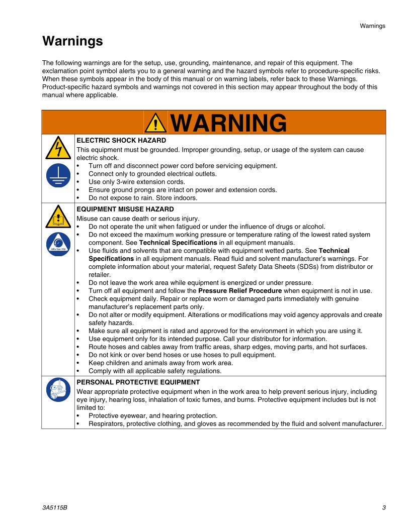
WarningsThe following warnings are for the setup, use, grounding, maintenance, and repair of this equipment. The exclamation point symbol alerts you to a general warning and the hazard symbols refer to procedure-specific risks. When these symbols appear in the body of this manual or on warning labels, refer back to these Warnings. Product-specific hazard symbols and warnings not covered in this section may appear throughout the body of this manual where applicable.
WARNINGELECTRIC SHOCK HAZARDThis equipment must be grounded. Improper grounding, setup, or usage of the system can cause electric shock.• Turn off and disconnect power cord before servicing equipment.• Connect only to grounded electrical outlets.• Use only 3-wire extension cords.• Ensure ground prongs are intact on power and extension cords.• Do not expose to rain. Store indoors.
EQUIPMENT MISUSE HAZARDMisuse can cause death or serious injury.• Do not operate the unit when fatigued or under the influence of drugs or alcohol.• Do not exceed the maximum working pressure or temperature rating of the lowest rated system
component. See Technical Specifications in all equipment manuals.• Use fluids and solvents that are compatible with equipment wetted parts. See Technical
Specifications in all equipment manuals. Read fluid and solvent manufacturer’s warnings. For complete information about your material, request Safety Data Sheets (SDSs) from distributor or retailer.
• Do not leave the work area while equipment is energized or under pressure.• Turn off all equipment and follow the Pressure Relief Procedure when equipment is not in use.• Check equipment daily. Repair or replace worn or damaged parts immediately with genuine
manufacturer’s replacement parts only.• Do not alter or modify equipment. Alterations or modifications may void agency approvals and create
safety hazards.• Make sure all equipment is rated and approved for the environment in which you are using it.• Use equipment only for its intended purpose. Call your distributor for information.• Route hoses and cables away from traffic areas, sharp edges, moving parts, and hot surfaces.• Do not kink or over bend hoses or use hoses to pull equipment.• Keep children and animals away from work area.• Comply with all applicable safety regulations.
PERSONAL PROTECTIVE EQUIPMENTWear appropriate protective equipment when in the work area to help prevent serious injury, including eye injury, hearing loss, inhalation of toxic fumes, and burns. Protective equipment includes but is not limited to:• Protective eyewear, and hearing protection.• Respirators, protective clothing, and gloves as recommended by the fluid and solvent manufacturer.

Installation
4 3A5115B
Installation
Grounding
Connect the Dispensit 4104A Dispense Valve Controller to earth ground.
1. Use ground wire and clamp (supplied). Loosen grounding lug locknut (S) and washer (T).
2. Insert ground wire end (U) into lug (V) slot and tighten locknut securely.
3. Connect ground clamp to a true earth ground.
For all other components in your system, follow the Grounding instructions described in your appropriate component manual. See Related Manuals on page 2 for more information.
AUTOMATIC SYSTEM ACTIVATION HAZARD
Unexpected activation of the system could result in serious injury, including skin injection and amputation.
When the Dispense Valve Controller is connected to a power source, the attached dispense valve becomes energized as well. Before installing or removing the Dispense Valve Controller from the system, disconnect all power and relieve all pressure.
The equipment must be grounded to reduce the risk of static sparking and electric shock. Electric or static sparking can cause fumes to ignite or explode. Improper grounding can cause electric shock. Grounding provides an escape wire for the electric current.
FIG. 1: Grounding Controller
SU T V

Installation
3A5115B 5
Control Panel
Key:A Controller Power Switch, see page 6B System Pressure Output GaugeC System Air Supply ConnectionD System Pressure Control KnobE Auxiliary Pressure GaugeF Auxiliary Pressure Control KnobG Reservoir Out ConnectionH Dispense TimerJ Dispense Valve Controller ReceptacleK Panel Mounted Trigger Switch
L Dispense Valve Control SwitchM Yellow Band ConnectorN Green Band ConnectorP Orange Band ConnectorR Clear Band ConnectorS Lug Locknut, see page 4T Washer, see page 4U Ground Wire, see page 4V Lug Slot, see page 4
FIG. 2: Front and Back Panel
FRONT PANEL
BACK PANEL
B
D
E
F
H
L K
J G
N
M P
R
C

Installation
6 3A5115B
• Controller power switch (A): turns the 4104A Controller ON or OFF.
• System pressure output gauge (B): displays air pressure as set by the operating pressure regulator knob (D).
• System air supply connection (C): supplies shop air to the controller.
• System pressure control knob (D): adjusts and maintains the system pressure for output to connections (M, N, P and R).
• Auxiliary pressure gauge (E): displays air pressure as set by the auxiliary pressure regulator knob (F).
• Auxiliary pressure control knob (F): adjusts and maintains the material pressure for output to connection (G).
• Reservoir out connection (G): supplies a regulated auxiliary air output for a material reservoir. The pressure is set by the auxiliary pressure control knob (F).
• Dispense timer (H): controls the length of time that there is air pressure to the dispense valve.
NOTE: See the TIMER ADJUSTMENT section of this manual for more information.
• Dispense valve controller receptacle (J): allows the connection of a foot switch. The foot switch, when actuated, causes the dispense valve to begin the dispense cycle.
• Panel mounted trigger switch (K): Pressing this switch will begin the controller’s dispense valve cycle.
NOTE: The panel mounted trigger switch is equivalent to the foot switch.
• Dispense valve control switch (L): Placing this switch in the AUTO position will cause the dispense valve portion of the controller to cycle when either the foot switch or the panel mounted trigger switch (K) is pressed. Placing this switch in the HAND position will cause the dispense cycle to begin, but the timer will not run and the dispense valve will purge the material.
• Yellow band connector (M): provides the air pressure as set by the system pressure control knob (D) to initiate the dispense cycle for some models.
• Green band connector (N): provides the air pressure as set by the system pressure control knob (D) to operate the lower pinch valve for some models, and the shift to reload function for other models.
• Orange band connector (P): provides the air pressure as set by the system pressure control knob (D) to initiate the dispense cycle for some valve models.
• Clear band connector (R): functions like the green band connection and may be used to connect a second dispense valve operating on the same dispense timing cycle as the first valve.
FIG. 3: Right Side of Panel
A

Setup
3A5115B 7
Setup
Setup ProcedurePlace the 4104A Dispense Valve Controller where it can be pneumatically connected to the dispense valve assembly and 70 psi (minimum) dry air.
1. Set the dispense timer (H) to approximately 2 seconds.
2. Set the dispense controller switch (L) to AUTO.
3. Turn the controller power switch (A) to OFF.
4. Turn the pneumatic air supply leading to the controller OFF.
5. Connect the air lines from the controller to the dispense valve according to the color codes on the controller and dispense valve. (Yellow to Yellow, Orange to Orange, etc.)
6. Connect the remaining air line to the controller’s reservoir connection.
7. Connect the foot switch to the controller receptacle plug (J).
8. Plug the controller in and turn the controller power switch (A) ON.
9. Connect the source air to the connection on the back of the controller.
System CheckoutComplete this checkout to verify that the system is setup correctly and operable.
1. Refer to the Setup Procedure and make sure that all knobs and switches are set correctly.
2. Make the appropriate adjustments so that there is at least two inches of clearance below the dispense valve.
3. Increase Reservoir pressure. Purge the dispense valve until you get a smooth flow of material from the valve outlet.
4. Set the dispense timer (H) to 2 seconds for start up.
5. Operate the foot switch and monitor the valve cycle. The dispense valve should emit a sound as it cycles. Watch for material being discharged through the valve outlet.
6. Adjust the dispense timer (H) until the timing is correct and the proper amount of material is dispensed.
7. Repeat steps 5-7 until the timers are properly adjusted.

Operation
8 3A5115B
OperationThis product should be used only by employees who have adequate training on operations and safety procedures as set forth in both the 4104A Dispense Valve Controller, and the appropriate dispense valve manuals. Disconnect the pneumatic air supply and the electrical power from both the 4104A Dispense Valve Controller and the dispense valve before servicing.
NOTE: ON/OFF switch is not a substitute for disconnecting electrical power.
Pressure Relief ProcedureFollow the Pressure Relief Procedure whenever you see this symbol.
To relieve pressure:
1. Disconnect the air supply.
2. Follow the Pressure Relief Procedure described in your appropriate dispense valve manual. See Related Manuals on page 2 for more information.
Sequence of Operation1. Set the dispense control switch (L) to the AUTO
position.
2. In systems that use a pressurized material reservoir, the desirable pressure for the material reservoir is set to the correct pressure by the material pressure control knob (F). Setting the pressure too low may result in little, or no, material being dispensed while the dispense valve cycles. Setting the pressure too high may cause the material to splatter as it is dispensed.
NOTE: Always start with material pressure. Then adjust the air pressure so that, in the purge mode, material flow will equal the dispense rate. This assures that material cavitation is not a problem.
3. Set the desirable dispense valve pressure (typically 70 psi) by adjusting the system pressure control knob (D). Setting the pressure too high may cause the operation to be abrupt and is not recommended. Setting the pressure too low may cause the shut off and/or dispensing to be incomplete.
4. A cycle begins when the switch connected to the dispense valve controller receptacle (J) is closed, or the panel mounted trigger switch (K) is pressed.
NOTE: This switch may either be a foot switch in simple applications, or an electronic switch in more sophisticated automatic applications.
5. The dispense valve begins to cycle when system air pressure is applied to the yellow and orange connections (M and P), which causes the dispense valve to dispense material. Air is relieved from the green and clear outlets (N and R).
6. At the completion of the time period set by the dispense timer (H), system air pressure is applied to the green and the clear outlets (N and R). Air is relieved from the yellow and the orange outlets (M and P).
7. This pressure closes off the dispense valve and stops the dispensing process.
8. When the system is refilled, it is ready to be triggered again.

Operation
3A5115B 9
Timer AdjustmentThis 4104A electronic timer is preprogrammed to cycle the dispense valve, ranging from 999.9 seconds to 1/10th of a second.
Changing Cycle TimeTo change the 4104A timer, perform the following steps:
1. By pressing the rocker up button (1) , this will increase the preset valve time by 0.1 second. By continuing to press the rocker button, the timer will continue to increase from 0 to 0.9 seconds (depending on the initial setting).The rocker down button will decrease the preset valve time.
2. By pressing the rocker up button (2) , this will increase the preset valve time by 1 second. By continuing to press the rocker button, the timer will continue to increase from 0 to 1 second (depending on the initial setting).The rocker down button will decrease the preset valve time.
3. By pressing the rocker up button (3) , this will increase the preset valve time by 10 seconds. By continuing to press the rocker button, the timer will continue to increase from 0 to 10 seconds (depending on the initial setting).The rocker down button will decrease the preset valve time.
4. By pressing the rocker up button (4) , this will increase the preset valve time by 100 seconds. By continuing to press the rocker button, the timer will continue to increase from 0 to 900 seconds (depending on the initial setting).The rocker down button will decrease the preset valve time.
5. Using steps 1 through 4, enter the cycle time in seconds. If there is a button that no time is required, press that button until 0 appears. When the start button is pressed, the current counter will start to increase, and the machine will cycle to the preset time. Once the current counter is equal to the preset time, the machine will stop cycling and the current counter will reset to 0.0 seconds.
NOTE: As an option, the LOCK button, when pressed, can disable the button to avoid accidental changing of the timer. If the lock is activated, the LOCK indicator will appear in the lower right corner of the timer display.
NOTE: The RESET button will set the current count to 0.0 seconds.
FIG. 4
Current Count
Preset Timein
0.1 seconds.

Operation
10 3A5115B
Changing Cycle Time ExampleTo enter in a 34 second cycle time, perform thefollowing steps:
1. To change the “4” in “34,” press the seconds button (2) until the number “4” appears on the display. 2. To change the “3” in “34” press the 10’s seconds
button (3) until the number “3” appears in the display.
3. The timer is now set for 34.0 seconds. When the start button is pressed, the current counter will start to increase, and the machine will cycle to the preset time. Once the current counter is equal to the preset time, the machine will stop cycling and the current counter will reset to 0.0 seconds.

Troubleshooting
3A5115B 11
Troubleshooting1. Follow the Pressure Relief Procedure, page 8,
before checking or repairing the Dispense Valve Controller.
2. Check all possible problems and causes before disassembling the Dispense Valve Controller.
Problem Cause Solution
Nothing Happens No power Check the electrical power and the pneumatic power.
Power not connected properly Check the foot switch to be sure it is plugged into its correct location.
Valve Cycles, Nothing Dispensed A portion of the material flow path is blocked
Try to purge the dispense valve; this should begin material flow.
Make sure that there is enough material pressure to the reservoir to move the material.
Examine/clear the entire path. Consider whether the material could have “set up” in the system. Refer to the dispense valve operating manual for cleaning.
Irregular Volume Dispensed Faulty material Replace material. The material must be a smooth (homogeneous) mixture, without any air entrapped in it.
The material is not filling the dispense tube fully and in time
Check the reservoir pressure as it may be set too low for the type of material being dispensed and/or the cycle time may be set too fast.
Reduced Volumes Dispensed Dispense tube requires replacement (models 700, 800, and 900 series)
Refer to the dispense valve operating manual for cleaning.
The needle is partially clogged
Slow or Sluggish Cycle Time Inadequate lubrication of the piston walls in the dispense valve
Refer to the dispense valve operating manual for proper lubrication procedures.
Dirty air filter located within the controller
Replace the internal air filter if needed.
“Hissing” Sound When Operating Air escaping from the air connections on the controller
Check all the air connections for proper installation.
Wiring Schematics
12 3A5115B
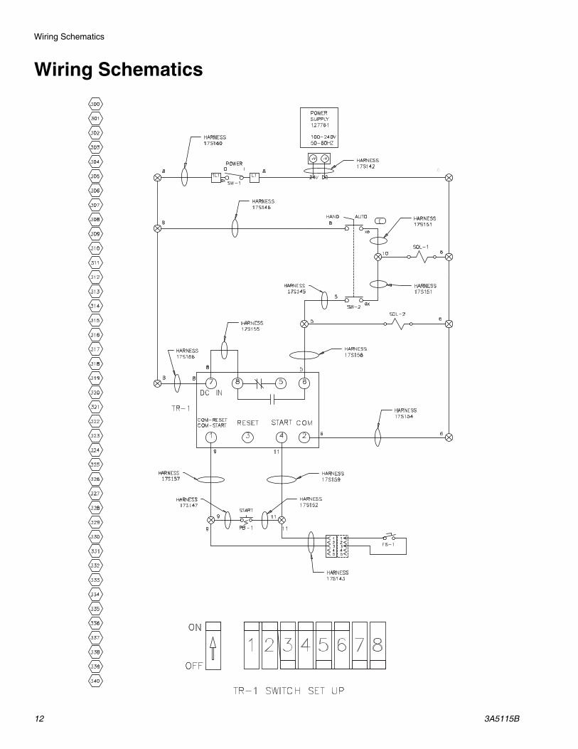
Wiring Schematics
6
SOL-1
POWERO I
HARNESS17S142
HARNESS17S160
HARNESS17S145
HARNESS17S151
HARNESS17S157
HARNESS17S147

Wiring Schematics
3A5115B 13
371
386
390
387
388
389
383
384
385
379
380
381
382
376
375
377
378
372
373
374
356
368
369
370
365
364
367
366
360
361
362
363
357
358
359
353
354
355
351
350
352
MATERIAL RESERVOIRBLACK
AUXILIARY 5-20 PSI
SYSTEM70 PSI
ORANGE
GREEN
CLEAR
YELLOW
DRY AIRIN
102
101 103
108
110
107
109
QD-1
QD-2
QD-3
QD-4
QD-5
G-2
REG-2
MF-1
100
SOL-1
SOL-2
104
104102
102
REG-1
G-1
100
RECOMMENDEDSTANDARD
STANDARDRECOMMENDED
105
101
106
24
15 3
(B)(A)
(R1) (P)(R2)
(R2)(P)(R1)315
24(A) (B)

Technical Specifications
14 3A5115B
Technical SpecificationsDispensit 4104A Controller
US MetricMaximum Air Input Pressure 100 psi 0.7 MPa, 7 barRequired Line Voltage 100-240 VAC, 50/60 Hz, 1 phase - 50 WattsMachine Operating Voltage 24 VDCMaximum Operating Temperatures 149° F 65° C
Inlet/Outlet SizesAir Inlet Size 1/4” NPT(f)Air Outlet Sizes 1/4” OD TubeWeight 16 lb 7.26 kg
DimensionsWidth - 12.00”Depth - 11.23” (15.52” w/ air shutoff)Height - 6.62”
Width - 12.00”Depth - 11.23” (15.52” w/ air shutoff)Height - 6.62”

Technical Specifications
3A5115B 15

All written and visual data contained in this document reflects the latest product information available at the time of publication. Graco reserves the right to make changes at any time without notice.
Original instructions. This manual contains English. MM 3A5115Graco Headquarters: Minneapolis
International Offices: Belgium, China, Japan, Korea
GRACO INC. AND SUBSIDIARIES • P.O. BOX 1441 • MINNEAPOLIS MN 55440-1441 • USACopyright 2017, Graco Inc. All Graco manufacturing locations are registered to ISO 9001.
www.graco.comRevision B, July 2017
Graco Standard WarrantyGraco warrants all equipment referenced in this document which is manufactured by Graco and bearing its name to be free from defects in material and workmanship on the date of sale to the original purchaser for use. With the exception of any special, extended, or limited warranty published by Graco, Graco will, for a period of twelve months from the date of sale, repair or replace any part of the equipment determined by Graco to be defective. This warranty applies only when the equipment is installed, operated and maintained in accordance with Graco’s written recommendations.
This warranty does not cover, and Graco shall not be liable for general wear and tear, or any malfunction, damage or wear caused by faulty installation, misapplication, abrasion, corrosion, inadequate or improper maintenance, negligence, accident, tampering, or substitution of non-Graco component parts. Nor shall Graco be liable for malfunction, damage or wear caused by the incompatibility of Graco equipment with structures, accessories, equipment or materials not supplied by Graco, or the improper design, manufacture, installation, operation or maintenance of structures, accessories, equipment or materials not supplied by Graco.
This warranty is conditioned upon the prepaid return of the equipment claimed to be defective to an authorized Graco distributor for verification of the claimed defect. If the claimed defect is verified, Graco will repair or replace free of charge any defective parts. The equipment will be returned to the original purchaser transportation prepaid. If inspection of the equipment does not disclose any defect in material or workmanship, repairs will be made at a reasonable charge, which charges may include the costs of parts, labor, and transportation.
THIS WARRANTY IS EXCLUSIVE, AND IS IN LIEU OF ANY OTHER WARRANTIES, EXPRESS OR IMPLIED, INCLUDING BUT NOT LIMITED TO WARRANTY OF MERCHANTABILITY OR WARRANTY OF FITNESS FOR A PARTICULAR PURPOSE.
Graco’s sole obligation and buyer’s sole remedy for any breach of warranty shall be as set forth above. The buyer agrees that no other remedy (including, but not limited to, incidental or consequential damages for lost profits, lost sales, injury to person or property, or any other incidental or consequential loss) shall be available. Any action for breach of warranty must be brought within two (2) years of the date of sale.
GRACO MAKES NO WARRANTY, AND DISCLAIMS ALL IMPLIED WARRANTIES OF MERCHANTABILITY AND FITNESS FOR A PARTICULAR PURPOSE, IN CONNECTION WITH ACCESSORIES, EQUIPMENT, MATERIALS OR COMPONENTS SOLD BUT NOT MANUFACTURED BY GRACO. These items sold, but not manufactured by Graco (such as electric motors, switches, hose, etc.), are subject to the warranty, if any, of their manufacturer. Graco will provide purchaser with reasonable assistance in making any claim for breach of these warranties.
In no event will Graco be liable for indirect, incidental, special or consequential damages resulting from Graco supplying equipment hereunder, or the furnishing, performance, or use of any products or other goods sold hereto, whether due to a breach of contract, breach of warranty, the negligence of Graco, or otherwise.
FOR GRACO CANADA CUSTOMERSThe Parties acknowledge that they have required that the present document, as well as all documents, notices and legal proceedings entered into, given or instituted pursuant hereto or relating directly or indirectly hereto, be drawn up in English. Les parties reconnaissent avoir convenu que la rédaction du présente document sera en Anglais, ainsi que tous documents, avis et procédures judiciaires exécutés, donnés ou intentés, à la suite de ou en rapport, directement ou indirectement, avec les procédures concernées.
Graco InformationSealant and Adhesive Dispensing Equipment
For the latest information about Graco products, visit www.graco.com.For patent information, see www.graco.com/patents.
TO PLACE AN ORDER, contact your Graco distributor, go to www.graco.com and select “Where to Buy” in the top blue bar, or call to find the nearest distributor.
If calling from the US: 800-746-1334If calling from outside the US: 0-1-330-966-3000