discrete input/output tpu function...
TRANSCRIPT

Order this document by TPUPN18/D
F
ree
sca
le S
em
ico
nd
uc
tor,
I
nc
...
Discrete Input/Output TPU Function (DIO)by Charles Melear
1 Functional OverviewThe discrete input/output (DIO) function allows the user to configure a time processor unit (TPU) chan-nel as an input or output. As an input, the channel can be read at any time or sampled at a periodic rate.As an output, the channel can be driven high or low upon command by the CPU.
A parameter RAM location, PIN_LEVEL, is used to record the 16 most recent states of the TPU channelpin. The programmer may choose one of the four following conditions to update the parameter: 1) whena transition (positive, negative, or either) occurs, 2) when the CPU makes a request to read the logicalvalue driving the pin, 3) when the CPU makes a request to drive the pin to a specified logical value or4) at a periodic rate specified in the MATCH_RATE register.
2 Detailed DescriptionThe DIO function allows a TPU channel pin to emulate a discrete input or output pin. As an input, thepin can be read either on command or at a periodic rate. As an output, the pin can be driven high or lowon command. The DIO function can be used in the following ways:
1. A TPU channel pin can be configured as an output and programmed to update on a host servicerequest. An HSR %10 outputs a low level onto the pin; an HSR %01 outputs a high level. Bothtypes of requests update bit 15 of PIN_LEVEL with the pin level driven on the pin. Each time ahost service request is issued to write a new value to the pin, the contents of the PIN_LEVELregister are shifted to the right by one bit and the new level on the TPU channel is written intobit 15 of that register. Note that if 16 consecutive commands were issued to drive a TPU chan-nel high, the PIN_LEVEL register would contain $FFFF. Likewise, if 16 consecutive commandswere issued to write a TPU channel alternately high and low, the PIN_LEVEL register wouldcontain $5555. The host sequence bits are not used for HSRs of %10 and %01.
2. A TPU channel can be configured as an input and programmed to update on positive transitionsonly, negative transitions only, or all transitions. This mode is entered by setting the host se-quence bits to %00 and issuing an HSR %11 (initialization).
Transition mode is normally used with the PAC field set to detect either transition. After 16 se-lected transitions occur, the PIN_LEVEL register contains $FFFF (positive edges only), $0000(negative edges only) or $5555 or $AAAA (both positive and negative edges). The update ofthe PIN_LEVEL register occurs any time a selected transition occurs. The time of the update isnot recorded.
3. A TPU channel can be configured as an input and programmed to update at match rate by set-ting the host sequence bits to %01 and then issuing an HSR %11. The match rate is specifiedin TPU clock cycles; either timer count register 1 (TCR1) or timer count register 2 (TCR2) canbe selected. At the rate specified in the MATCH_RATE register, the contents of the associatedPIN_LEVEL register are shifted to the right by one place and the logic level of the TPU channelis loaded into bit 15 of the PIN_LEVEL register. Match mode operation is normally used withthe input pin configured by PAC to ignore transitions.
Match mode always uses TCR1 to set up the first compare interval during initialization even ifTCR2 is specified in the TBS field of the channel control register. Subsequent matches occurat the TCR2 rate as specified by MATCH_RATE.
© MOTOROLA INC, 1997For More Information On This Product,
Go to: www.freescale.com

Fre
esc
ale
Se
mic
on
du
cto
r, I
Freescale Semiconductor, Inc.n
c..
.
4. A TPU channel can be configured as an input and programmed to update on a host servicerequest. This mode is entered by setting the host sequence bits to %00 and issuing an HSR%11 (initialization). To read the pin, set the host sequence bits to %10 and then issue an HSR%11 (initialization). Each time the appropriate HSR is issued the contents of the associatedPIN_LEVEL register are shifted to the right by one place and the logic level of the TPU channelis loaded into bit 15 of the PIN_LEVEL register.
If a host service request for initialization coincides with a scheduled request by a match or tran-sition, the host request receives priority and the other request is ignored. HSR %11 should notbe used when the host sequence bits are also %11, as errors result.
3 Function Code SizeTotal TPU function code size determines what combination of functions can fit into a given ROM or em-ulation memory microcode space. DIO function code size is:
12 µ instructions + 7 entries = 19 long words
4 DIO Function ParametersThis section provides detailed descriptions of discrete input/output function parameters stored in chan-nel parameter RAM. Figure 1 shows TPU parameter RAM address mapping. Figure 2 shows the pa-rameter RAM assignment used by the DIO function. In the diagrams, Y = M111, where M is the valueof the module mapping bit (MM) in the system integration module configuration register (Y = $7 or $F).
— = Not Implemented (reads as $00)
Figure 1 TPU Channel Parameter RAM CPU Address Map
Channel Base Parameter Address
Number Address 0 1 2 3 4 5 6 7
0 $YFFF## 00 02 04 06 08 0A — —
1 $YFFF## 10 12 14 16 18 1A — —
2 $YFFF## 20 22 24 26 28 2A — —
3 $YFFF## 30 32 34 36 38 3A — —
4 $YFFF## 40 42 44 46 48 4A — —
5 $YFFF## 50 52 54 56 58 5A — —
6 $YFFF## 60 62 64 66 68 6A — —
7 $YFFF## 70 72 74 76 78 7A — —
8 $YFFF## 80 82 84 86 88 8A — —
9 $YFFF## 90 92 94 96 98 9A — —
10 $YFFF## A0 A2 A4 A6 A8 AA — —
11 $YFFF## B0 B2 B4 B6 B8 BA — —
12 $YFFF## C0 C2 C4 C6 C8 CA — —
13 $YFFF## D0 D2 D4 D6 D8 DA — —
14 $YFFF## E0 E2 E4 E6 E8 EA EC EE
15 $YFFF## F0 F2 F4 F6 F8 FA FC FE
TPU Programming Library2 TPUPN18/D
For More Information On This Product,
Go to: www.freescale.com

Fre
esc
ale
Se
mic
on
du
cto
r, I
Freescale Semiconductor, Inc.n
c..
.
W = Channel number
Figure 2 DIO Function Parameter RAM Assignment
4.1 CHANNEL_CONTROL
The CPU should write CHANNEL_CONTROL prior to issuing an initialization HSR. TheCHANNEL_CONTROL parameter configures the PSC, PAC, and TBS fields. The PSC field is not usedby the DIO function and should be set to “no change”. The PAC field specifies the pin logic responsefor a timer channel input. PAC should be set to “detect either edge” for transition mode and to “no tran-sitions detected” for match mode. For discrete input, the TBS field selects the time base to be used forMATCH_RATE comparisons. (TCR1 is recommended.) For discrete output, this field is a “don't care”.The following table defines the allowable data for this parameter.
15 14 13 12 11 10 9 8 7 6 5 4 3 2 1 0
$YFFFW0 CHANNEL_CONTROL
$YFFFW2 PIN_LEVEL
$YFFFW4 MATCH_RATE
$YFFFW6
$YFFFW8
$YFFFWA
Parameter Write Access:
Written by CPU
Written by TPU
Written by CPU and TPU
Unused parameters
15 14 13 12 11 10 9 8 7 6 5 4 3 2 1 0
NOT USED TBS PAC PSC
Table 1 DIO CHANNEL_CONTROL Options
TBS PAC PSC Action
8 7 6 5 4 3 2 1 0 Input Output
1 1 — Do Not Force
0 0 00 0 10 1 00 1 11 x x
Do Not Detect TransitionDetect Rising EdgeDetect Falling EdgeDetect Either EdgeDo Not Change PAC
————
Do Not Change PAC
0 0 x x0 0 0 00 0 0 10 0 1 00 0 1 11 x x x
Input ChannelCapture TCR1, Match TCR1Capture TCR1, Match TCR2Capture TCR2, Match TCR1Capture TCR2, Match TCR2Do Not Change TBS
—————
Do Not Change TBS
TPU Programming LibraryTPUPN18/D 3
For More Information On This Product,
Go to: www.freescale.com

Fre
esc
ale
Se
mic
on
du
cto
r, I
Freescale Semiconductor, Inc.n
c..
.
4.2 PIN_LEVEL
PIN_LEVEL indicates the 16 most recent pin values, with the most recent pin value contained in bit 15and the least recent pin value contained in bit 0. The TPU writes this parameter when a specified tran-sition occurs, or a match or host request to read the pin state occurs, depending on the mode of oper-ation. When updated, the 16 most recent pin values are shifted right by one and the most recent pinvalue is placed into bit 15. The pin value contained in bit 0 before the right shift is lost after the data isshifted right by one.
4.3 MATCH_RATE
MATCH_RATE indicates the rate, expressed in cycles of the selected TCR, at which the pin value isrecorded in PIN_LEVEL when the channel is executing match mode operation.
5 Host Interface to FunctionThis section provides information concerning the TPU host interface to the DIO function. Figure 3 is aTPU address map. Detailed TPU register diagrams follow the figure. In the diagrams, Y = M111, whereM is the value of the module mapping bit (MM) in the system integration module configuration register(Y = $7 or $F).
Figure 3 TPU Address Map
Address 15 8 7 0
$YFFE00 TPU MODULE CONFIGURATION REGISTER (TPUMCR)
$YFFE02 TEST CONFIGURATION REGISTER (TCR)
$YFFE04 DEVELOPMENT SUPPORT CONTROL REGISTER (DSCR)
$YFFE06 DEVELOPMENT SUPPORT STATUS REGISTER (DSSR)
$YFFE08 TPU INTERRUPT CONFIGURATION REGISTER (TICR)
$YFFE0A CHANNEL INTERRUPT ENABLE REGISTER (CIER)
$YFFE0C CHANNEL FUNCTION SELECTION REGISTER 0 (CFSR0)
$YFFE0E CHANNEL FUNCTION SELECTION REGISTER 1 (CFSR1)
$YFFE10 CHANNEL FUNCTION SELECTION REGISTER 2 (CFSR2)
$YFFE12 CHANNEL FUNCTION SELECTION REGISTER 3 (CFSR3)
$YFFE14 HOST SEQUENCE REGISTER 0 (HSQR0)
$YFFE16 HOST SEQUENCE REGISTER 1 (HSQR1)
$YFFE18 HOST SERVICE REQUEST REGISTER 0 (HSRR0)
$YFFE1A HOST SERVICE REQUEST REGISTER 1 (HSRR1)
$YFFE1C CHANNEL PRIORITY REGISTER 0 (CPR0)
$YFFE1E CHANNEL PRIORITY REGISTER 1 (CPR1)
$YFFE20 CHANNEL INTERRUPT STATUS REGISTER (CISR)
$YFFE22 LINK REGISTER (LR)
$YFFE24 SERVICE GRANT LATCH REGISTER (SGLR)
$YFFE26 DECODED CHANNEL NUMBER REGISTER (DCNR)
TPU Programming Library4 TPUPN18/D
For More Information On This Product,
Go to: www.freescale.com

Fre
esc
ale
Se
mic
on
du
cto
r, I
Freescale Semiconductor, Inc.n
c..
.
CFS[4:0] — Function Number (Assigned during microcode assembly)CIER — Channel Interrupt Enable Register $YFFE0A
15 14 13 12 11 10 9 8 7 6 5 4 3 2 1 0
CH 15 CH 14 CH 13 CH 12 CH 11 CH 10 CH 9 CH 8 CH 7 CH 6 CH 5 CH 4 CH 3 CH 2 CH 1 CH 0
CH Interrupt Enable
0 Channel interrupts disabled
1 Channel interrupts enabled
CFSR[0:3] — Channel Function Select Registers $YFFE0C – $YFFE12
15 14 13 12 11 10 9 8 7 6 5 4 3 2 1 0
CFS (CH 15, 11, 7, 3) CFS (CH 14, 10, 6, 2) CFS (CH 13, 9, 5, 1) CFS (CH 12, 8, 4, 0)
HSQR[0:1] — Host Sequence Registers $YFFE14 – $YFFE16
15 14 13 12 11 10 9 8 7 6 5 4 3 2 1 0
CH 15, 7 CH 14, 6 CH 13, 5 CH 12, 4 CH 11, 3 CH 10, 2 CH 9, 1 CH 8, 0
CH[15:0] Action Taken
00 Transition mode: record pin on transition
01 Match mode: record pin at MATCH_RATE
10 Record pin state on HSR%11
11 Indeterminate operation
HSRR[0:1] — Host Service Request Registers $YFFE18 – $YFFE1A
15 14 13 12 11 10 9 8 7 6 5 4 3 2 1 0
CH 15, 7 CH 14, 6 CH 13, 5 CH 12, 4 CH 11, 3 CH 10, 2 CH 9, 1 CH 8, 0
CH[15:0] Initialization
00 No host service (reset condition)
01 Force high output
10 Force low output
11 Initialize as per host sequence bits
CPR[1:0] — Channel Priority Registers $YFFE1C – $YFFE1E
15 14 13 12 11 10 9 8 7 6 5 4 3 2 1 0
CH 15, 7 CH 14, 6 CH 13, 5 CH 12, 4 CH 11, 3 CH 10, 2 CH 9, 1 CH 8, 0
CH[15:0] Channel Priority
00 Disabled
01 Low
10 Middle
11 High
TPU Programming LibraryTPUPN18/D 5
For More Information On This Product,
Go to: www.freescale.com

Fre
esc
ale
Se
mic
on
du
cto
r, I
Freescale Semiconductor, Inc.n
c..
.
6 Function ConfigurationFor discrete input, the host CPU initializes the channel by:
1. Writing parameters CHANNEL_CONTROL and MATCH_RATE;2. Writing host sequence bits to configure transition or match mode, as desired;3. Writing host service request bits to request initialization (%11).
The TPU then executes initialization and accepts an input transition type specified by the PAC field inCHANNEL_CONTROL, or samples the state of the pin at the rate specified by MATCH_RATE. TheCPU should monitor the HSR register until the TPU clears the service request to %00 before changingany parameters or before issuing a new service request to this channel.
For discrete output, the host CPU initializes the channel by the following:
1. Writing %01 to the HSR bits; causing the TPU to output a high level to the pin; or,2. Writing %10 to the HSR bits; causing the TPU to output a low level to the pin.
No other initialization is required.
For all modes of discrete input, once initialized, and discrete output, configuring the host sequence bitsto %10 and issuing %11 to the HSR bits causes the TPU to read the pin level and to record the levelread in bit 15 of PIN_LEVEL. In the case of discrete output, the pin level read is the state of the outputlatch, and not the level of the pin at the pad. In all cases, whenever the pin level is recorded in bit 15 ofPIN_LEVEL, an interrupt is generated (if enabled).
Note that to switch from discrete output to discrete input, the host sequence bits must be configured forthe proper mode of operation and initialization executed. To switch from discrete input to discrete out-put, no initialization is required; only the proper HSR must be initiated to force the proper output pin lev-el.
7 Performance and Use of Function
7.1 Performance
Like all TPU functions, DIO function performance in an application is to some extent dependent uponthe service time (latency) of other active TPU channels. This is due to the operational nature of thescheduler. The more TPU channels are active, the more performance decreases. Worst-case latencyin any TPU application can be closely estimated. To analyze the performance of an application that ap-pears to approach the limits of the TPU, use the guidelines given in the TPU reference manual and theinformation in the DIO state timing table below.
CISR — Channel Interrupt Status Register $YFFE20
15 14 13 12 11 10 9 8 7 6 5 4 3 2 1 0
CH 15 CH 14 CH 13 CH 12 CH 11 CH 10 CH 9 CH 8 CH 7 CH 6 CH 5 CH 4 CH 3 CH 2 CH 1 CH 0
CH Interrupt Status
0 Channel interrupt not asserted
1 Channel interrupt asserted
TPU Programming Library6 TPUPN18/D
For More Information On This Product,
Go to: www.freescale.com

Fre
esc
ale
Se
mic
on
du
cto
r, I
Freescale Semiconductor, Inc.n
c..
.
7.2 Changing Mode
The host sequence bits are used to select DIO function operating mode. Change host sequence bit val-ues only when the function is stopped or disabled (channel priority bits = %00). Disabling the channelbefore changing mode avoids conditions that cause indeterminate operation.
8 Function ExamplesThe following examples give an indication of the capabilities of the DIO function. Each example includesa description of the example, a diagram of the initial parameter RAM content, a diagram of the outputwaveform, and a program listing.
8.1 Example A
8.1.1 Description
This example sets up TPU channels 0, 5, 10, and 15 as outputs and causes them to go high or low byissuing the appropriate host service requests. Four square waves are generated at frequencies of f, 2f,4f, and 8f.
8.1.2 Initialization
Configure the CHANNEL_CONTROL register for channels 0, 5, 10, and 15 as follows:
Table 2 DIO State Timing
State Number and Name Max CPU Clock Cycles RAM Accesses by TPU
S1 Init 18 4
S2 Match_PS 10 3
S3 Trans_PS_Low 4 2
S4 Trans_PS_High 4 2
S5 Low_Pin_Request 8 2
S6 High_Pin_Request 8 2
Table 3 DIO CHANNEL_CONTROL Parameter
15 8 7 0
$YFFF00 0 0 0 0 0 0 0 0 0 0 0 0 0 0 1 1 Channel 0
$YFFF50 0 0 0 0 0 0 0 0 0 0 0 0 0 0 1 1 Channel 5
$YFFFA0 0 0 0 0 0 0 0 0 0 0 0 0 0 0 1 1 Channel 10
$YFFFF0 0 0 0 0 0 0 0 0 0 0 0 0 0 0 1 1 Channel 15
TPU Programming LibraryTPUPN18/D 7
For More Information On This Product,
Go to: www.freescale.com

Fre
esc
ale
Se
mic
on
du
cto
r, I
Freescale Semiconductor, Inc.n
c..
.
8.1.3 Output Waveforms
8.1.4 Program Listing1 2 * The following program uses TPU channels 0, 5, 10 and 15 in the Discrete3 * Input/Output mode. The purpose of this example is to 4 * set up the channels as outputs and then cause them to go high or low5 * by issuing the appropriate Host Service Requests. Four square waves will6 * be generated at frequencies of f, 2f, 4f and 8f.7 8 * This section of the program assigns names to the registers address.9 00000000 10 TPUMCR equ $fffe00 ;TPU Module Configuration Reg00000000 11 TTCR equ $fffe0200000000 12 DSCR equ $fffe0400000000 13 DSSR equ $fffe0600000000 14 TICR equ $fffe08 ;TPU Interrupt Config. Reg00000000 15 CIER equ $fffe0a ;TPU Ch. Interrupt Enable Reg00000000 16 CFSR0 equ $fffe0c ;TPU Ch. Function Select Reg 000000000 17 CFSR1 equ $fffe0e ;TPU Ch. Function Select Reg 100000000 18 CFSR2 equ $fffe10 ;TPU Ch. Function Select Reg 200000000 19 CFSR3 equ $fffe12 ;TPU Ch. Function Select Reg 300000000 20 HSQR0 equ $fffe14 ;TPU Host Sequence Register 000000000 21 HSQR1 equ $fffe16 ;TPU Host Sequence Register 100000000 22 HSRR0 equ $fffe18 ;TPU Host Service Req. Reg 000000000 23 HSRR1 equ $fffe1a ;TPU Host Service Req. Reg 100000000 24 CPR0 equ $fffe1c ;TPU Channel Priority Reg 000000000 25 CPR1 equ $fffe1e ;TPU Channel Priority Reg 100000000 26 CISR equ $fffe20 ;Channel Interrupt Status Reg00000000 27 CH0_CNTL equ $ffff00 ;Channel 0 Control Reg00000000 28 CH0_PINL equ $ffff02 ;Channel 0 Pin Level Reg00000000 29 CH0_MATCH equ $ffff04 ;Channel 0 Match Rate Reg00000000 30 CH5_CNTL equ $ffff50 ;Channel 5 Control Register00000000 31 CH5_PINL equ $ffff52 ;Channel 5 Pin Level Register00000000 32 CH5_MATCH equ $ffff54 ;Channel 5 Match Rate Register00000000 33 CH10_CNTL equ $ffffa0 ;Channel 10 Control Register00000000 34 CH10_PINL equ $ffffa2 ;Ch. 10 Pin Level Register00000000 35 CH10_MATCH equ $ffffa4 ;Ch. 10 Match Rate Register00000000 36 CH15_CNTL equ $fffff0 ;Ch. 15 Control Register00000000 37 CH15_PINL equ $fffff2 ;Ch. 15 Pin Level Register00000000 38 CH15_MATCH equ $fffff4 ;Channel 15 Match Rate Register 39 00005000 40 org $5000 ;program origin41 * This portion of the program initializes the TPU reg41 00005000 33FC8000 42 init move.w #$8000,(CFSR0).l ;init ch. 15 to DIO function
00FFFE0C 00005008 33FC0800 43 move.w #$0800,(CFSR1).l ;init ch. 10 to DIO function
00FFFE0E
CHANNEL 0
CHANNEL 5
CHANNEL 10
CHANNEL 15
TPU DIO EX TIM
TPU Programming Library8 TPUPN18/D
For More Information On This Product,
Go to: www.freescale.com

Fre
esc
ale
Se
mic
on
du
cto
r, I
Freescale Semiconductor, Inc.n
c..
.
00005010 33FC0080 44 move.w #$0080,(CFSR2).l ;init ch. 5 to DIO function00FFFE10
00005018 33FC0008 45 move.w #$0008,(CFSR3).l ;init ch. 0 to DIO function00FFFE12
00005020 33FC0000 46 move.w #$0000,(HSQR0).l ;ch. 15,10 pin level00FFFE14 ;reg. update on HSR = 11
00005028 33FC0000 47 move.w #$0000,(HSQR1).l ;ch. 5,0 pin level 00FFFE16 ;reg. update on HSR = 11
00005030 33FCC030 48 move.w #$c030,(CPR0).l ;ch. 15,10 - hi priority00FFFE1C
00005038 33FC0C03 49 move.w #$0c03,(CPR1).l ;ch. 5,0 - hi priority00FFFE1E
00005040 33FC0003 50 move.w #$0003,(CH15_CNTL).l;ch. 15 - use TCR1 00FFFFF0
00005048 33FC0003 51 move.w #$0003,(CH10_CNTL).l;ch. 10 use TCR100FFFFA0
00005050 33FC0003 52 move.w #$0003,(CH5_CNTL).l ;ch. 5 use TCR100FFFF50
00005058 33FC0003 53 move.w #$0003,(CH0_CNTL).l ;ch. 0 use TCR100FFFF00
54 55 * This portion of the program only initializes the DIO channels as outputs.56 * No action will be taken on an external pin by executing the next two57 * instructions.
58 00005060 33FCC030 59 move.w #$c030,(HSRR0).l ;HSR - init ch. 15,10
00FFFE18 00005068 33FC0C03 60 move.w #$0c03,(HSRR1).l ;HSR - init ch. 5,0
00FFFE1A 61 62 * This portion of the program generates four square waves using software63 * timing loops.64 00005070 33FC8020 65 strt move.w #$8020,(HSRR0).l ;HSR - ch. 15-lo, c
00FFFE18 00005078 33FC0802 65 move.w #$0802,(HSRR1).l ;HSR ch 5-lo,ch 0-lo
00FFFE1A 00005080 4EB90000 66 jsr wait
518C 00005086 33FC0801 67 move.w #$0801,(HSRR1).l ;HSR - ch. 0 - hi
00FFFE1A 0000508E 4EB90000 68 jsr wait
518C 00005094 33FC0402 69 move.w #$0402,(HSRR1).l ;HSR ch. 5-hi, ch0-lo
00FFFE1A 0000509C 4EB90000 70 jsr wait
518C 000050A2 33FC0401 71 move.w #$0401,(HSRR1).l ;HSR ch 5-hi, ch 0-hi
00FFFE1A 000050AA 4EB90000 72 jsr wait
518C 000050B0 33FC0802 73 move.w #$0802,(HSRR1).l ;HSR ch 5-lo, ch 0-lo
00FFFE1A 000050B8 33FC0010 74 move.w #$0010,(HSRR0).l ;HSR - ch. 15 - lo, c
00FFFE18 000050C0 4EB90000 74 jsr wait
518C 000050C6 33FC0801 75 move.w #$0801,(HSRR1).l ;HSR ch 5-lo, ch 0-hi
00FFFE1A 000050CE 33FC8010 76 move.w #$8010,(HSRR0).l ;HSR - ch. 15 - lo, c
00FFFE18 000050D6 4EB90000 76 jsr wait
518C 000050DC 33FC0402 77 move.w #$0402,(HSRR1).l ;HSR ch 5-hi, ch 0-lo
00FFFE1A 000050E4 33FC8010 78 move.w #$8010,(HSRR0).l ;HSR - ch. 15 - lo, c
TPU Programming LibraryTPUPN18/D 9
For More Information On This Product,
Go to: www.freescale.com

Fre
esc
ale
Se
mic
on
du
cto
r, I
Freescale Semiconductor, Inc.n
c..
.
00FFFE18 000050EC 4EB90000 78 jsr wait
518C 000050F2 33FC0401 79 move.w #$0401,(HSRR1).l ;HSR ch 5-hi, ch 0-hi
00FFFE1A 000050FA 33FC8010 80 move.w #$8010,(HSRR0).l ;HSR - ch. 15 - lo, c
00FFFE18 00005102 4EB90000 80 jsr wait
518C 00005108 33FC0802 81 move.w #$0802,(HSRR1).l ;HSR ch. 5-lo, ch 0-lo
00FFFE1A 00005110 33FC4020 82 move.w #$4020,(HSRR0).l ;HSR ch. 15-hi, c
00FFFE18 00005118 4EB90000 82 jsr wait
518C 0000511E 33FC0801 83 move.w #$0801,(HSRR1).l ;HSR ch. 5-lo, ch 0-hi
00FFFE1A 00005126 4EB90000 84 jsr wait
518C 0000512C 33FC0402 85 move.w #$0402,(HSRR1).l ;HSR ch 5-hi, ch 0-lo
00FFFE1A 00005134 4EB90000 86 jsr wait
518C 0000513A 33FC0401 87 move.w #$0401,(HSRR1).l ;HSR ch 5-hi, ch 0-hi
00FFFE1A 00005142 4EB90000 88 jsr wait
518C 00005148 33FC0802 89 move.w #$0802,(HSRR1).l ;HSR-ch. 5-lo, ch. 0-lo
00FFFE1A 00005150 33FC4010 90 move.w #$4010,(HSRR0).l ;HSR - ch. 15 - hi, c
00FFFE18 00005158 4EB90000 90 jsr wait
518C 0000515E 33FC0801 91 move.w #$0801,(HSRR1).l ;HSR ch. 5-lo, ch 0-hi
00FFFE1A 00005166 4EB90000 92 jsr wait
518C 0000516C 33FC0402 93 move.w #$0402,(HSRR1).l ;HSR ch 5-hi, ch 0-lo
00FFFE1A 00005174 4EB90000 94 jsr wait
518C 0000517A 33FC0401 95 move.w #$0401,(HSRR1).l ;HSR ch 5-hi, ch 0-lo
00FFFE1A 00005182 4EB90000 96 jsr wait
518C 00005188 4EF85070 97 jmp strt0000518C 203C0000 98 wait move.l #$fff,d0 ;wait loop
0FFF 00005192 90BC0000 99 loop1sub.l #$1,d0 ;wait loop
0001 00005198 6600FFF8 100 bne loop1 ;wait loop0000519C 4E75 101 rts
102 103 104 105 106
TPU Programming Library10 TPUPN18/D
For More Information On This Product,
Go to: www.freescale.com

Fre
esc
ale
Se
mic
on
du
cto
r, I
Freescale Semiconductor, Inc.n
c..
.
8.2 Example B
8.2.1 Description
This program uses TPU channels 0, 2, 5, 6, 10, 11, 14, and 15 with the discrete output function. Theprogram sets up channels 0, 5, 10, and 15 as outputs and then causes them to go high or low by issuingthe appropriate host service requests. Four square waves are generated at frequencies of f, 2f, 4f, and8f. In addition, TPU channels 2, 6, 11, and 14 are configured as inputs and update their PIN_LEVELregisters on each transition. Channel 0 drives channel 2, channel 5 drives channel 6, channel 10 driveschannel 11, and channel 16 drives channel 14. The PIN_LEVEL registers of the input channels will allcontain $5555 or $AAAA after 16 transitions have been detected on the slowest channel.
8.2.2 Hardware Configuration
8.2.3 Initialization
Configure the CHANNEL_CONTROL registers as follows:
Table 4 DIO CHANNEL_CONTROL Parameter
15 8 7 0
$YFFF00 0 0 0 0 0 0 0 0 0 0 0 0 0 0 1 1 Channel 0
$YFFF50 0 0 0 0 0 0 0 0 0 0 0 0 0 0 1 1 Channel 5
$YFFFA0 0 0 0 0 0 0 0 0 0 0 0 0 0 0 1 1 Channel 10
$YFFFF0 0 0 0 0 0 0 0 0 0 0 0 0 0 0 1 1 Channel 15
$YFFF20 0 0 0 0 0 0 0 0 0 0 0 0 1 1 1 1 Channel 2
$YFFF60 0 0 0 0 0 0 0 0 0 0 0 0 1 1 1 1 Channel 6
$YFFFB0 0 0 0 0 0 0 0 0 0 0 0 0 1 1 1 1 Channel 11
$YFFFE0 0 0 0 0 0 0 0 0 0 0 0 0 1 1 1 1 Channel 14
TPU DIO EX CONN
CHANNEL 0
CHANNEL 2
CHANNEL 5
CHANNEL 6
CHANNEL 10
CHANNEL 11
CHANNEL 14
CHANNEL 15
TPU
TPU Programming LibraryTPUPN18/D 11
For More Information On This Product,
Go to: www.freescale.com

Fre
esc
ale
Se
mic
on
du
cto
r, I
Freescale Semiconductor, Inc.n
c..
.
8.2.4 Output Waveforms
8.2.5 Program Listing1 2 * The following program uses TPU channels 0, 2, 5, 6, 10, 11, 14 and 15 in the3 * Discrete Input/Output mode. This program sets up channels 0, 5, 10 and 154 * as outputs and then cause them to go high or low5 * by issuing the appropriate Host Service Requests. Four square waves will6 * be generated at frequencies of f, 2f, 4f and 8f. TPU channels 2, 6, 7 * 11 and 14 will be configured as inputs and will update their PIN_LEVEL8 * Registers on each transition. Channel 0 will drive channel 2, channel 59 * will drive channel 6, channel 10 will drive channel 11 and channel 15 will10 * drive channel 14. The PIN_LEVEL Registers of the input channels should all11 * contain $5555 or $AAAA after 16 transitions have been detected on the 12 * slowest channel.13 14 * This section of the program assigns register names to the reg. address.15 00000000 16 TPUMCR equ $fffe00 ;TPU Module Config. Reg00000000 17 TTCR equ $fffe0200000000 18 DSCR equ $fffe0400000000 19 DSSR equ $fffe0600000000 20 TICR equ $fffe08 ;TPU Interrupt Config. Reg00000000 21 CIER equ $fffe0a ;TPU Channel Interrupt Enable Reg00000000 22 CFSR0 equ $fffe0c ;TPU Ch. Function Select Reg 000000000 23 CFSR1 equ $fffe0e ;TPU Ch. Function Select Reg 100000000 24 CFSR2 equ $fffe10 ;TPU Ch. Function Select Reg 200000000 25 CFSR3 equ $fffe12 ;TPU Ch. Function Select Reg 300000000 26 HSQR0 equ $fffe14 ;TPU Host Sequence Reg 000000000 27 HSQR1 equ $fffe16 ;TPU Host Sequence Reg 100000000 28 HSRR0 equ $fffe18 ;TPU Host Svc. Request Reg 000000000 29 HSRR1 equ $fffe1a ;TPU Host Svc Request Reg 100000000 30 CPR0 equ $fffe1c ;TPU Channel Priority Reg 000000000 31 CPR1 equ $fffe1e ;TPU Channel Priority Reg 100000000 32 CISR equ $fffe20 ;Channel Int. Status Reg00000000 33 CH0_CNTL equ $ffff00 ;Channel 0 Control Register00000000 34 CH0_PINL equ $ffff02 ;Channel 0 Pin Level Reg00000000 35 CH0_MATCH equ $ffff04 ;Channel 0 Match Rate Reg00000000 36 CH2_CNTL equ $ffff20 ;Channel 2 Control Reg00000000 37 CH2_PINL equ $ffff22 ;Channel 2 Pin Level Reg00000000 38 CH2_MATCH equ $ffff24 ;Channel 2 Match Rate Reg00000000 39 CH5_CNTL equ $ffff50 ;Channel 5 Control Reg00000000 40 CH5_PINL equ $ffff52 ;Channel 5 Pin Level Reg00000000 41 CH5_MATCH equ $ffff54 ;Channel 5 Match Rate Reg00000000 42 CH6_CNTL equ $ffff60 ;Channel 6 Control Reg00000000 43 CH6_PINL equ $ffff62 ;Channel 6 Pin Level Reg00000000 44 CH6_MATCH equ $ffff64 ;Channel 6 Match Rate Reg00000000 45 CH10_CNTL equ $ffffa0 ;Channel 10 Control Reg
46 CH10_PINL equ $ffffa2 ;Channel 10 Pin Level Reg
CHANNEL 0
CHANNEL 5
CHANNEL 10
CHANNEL 15
TPU DIO EX TIM
TPU Programming Library12 TPUPN18/D
For More Information On This Product,
Go to: www.freescale.com

Fre
esc
ale
Se
mic
on
du
cto
r, I
Freescale Semiconductor, Inc.n
c..
.
00000000 47 CH10_MATCH equ $ffffa4 ;Channel 10 Match Rate Reg00000000 48 CH11_CNTL equ $ffffb0 ;Channel 11 Control Reg00000000 49 CH11_PINL equ $ffffb2 ;Channel 11 Pin Level Reg00000000 50 CH11_MATCH equ $ffffb4 ;Channel 11 Match Rate Reg00000000 51 CH14_CNTL equ $ffffe0 ;Channel 14 Control Reg00000000 52 CH14_PINL equ $ffffe2 ;Channel 14 Pin Level Reg00000000 53 CH14_MATCH equ $ffffe4 ;Channel 14 Match Rate Reg00000000 54 CH15_CNTL equ $fffff0 ;Channel 15 Control Reg00000000 55 CH15_PINL equ $fffff2 ;Channel 15 Pin Level Reg00000000 56 CH15_MATCH equ $fffff4 ;Channel 15 Match Rate Reg 57 00005000 58 org $5000 ;program origin 59 * This portion of the program initializes the TPU registers 59 00005000 33FC8800 60 init move.w #$8800,(CFSR0).l ;init ch 15,14 to DIO
00FFFE0C 00005008 33FC8800 61 move.w #$8800,(CFSR1).l ;init ch 10,11 to DIO
00FFFE0E 00005010 33FC0880 62 move.w #$0880,(CFSR2).l ;init ch 5,6 to DIO
00FFFE10 00005018 33FC0808 63 move.w #$0808,(CFSR3).l ;init ch 0,2 to DIO
00FFFE12 00005020 33FC0000 64 move.w #$0000,(HSQR0).l ;ch. 15,14,11,10 pin level
00FFFE14 ;reg. update on transition00005028 33FC0000 65 move.w #$0000,(HSQR1).l ;ch.5,6,2,0 pin level
00FFFE16 ;reg. update on transition00005030 33FCF0F0 66 move.w #$f0f0,(CPR0).l ;ch. 15,14,10,11 have
00FFFE1C ;high priority00005038 33FC3C33 67 move.w #$3c33,(CPR1).l ;ch. 5,6 and 2,0 have
00FFFE1E ;high priority00005040 33FC0003 68 move.w #$0003,(CH15_CNTL).l;ch. 15 use TCR1
00FFFFF0 00005048 33FC000F 69 move.w #$000f,(CH14_CNTL).l;ch. 14 use TCR1
00FFFFE0 ;detect both edges00005050 33FC000F 70 move.w #$000f,(CH11_CNTL).l;ch. 11 use TCR1
00FFFFB0 ;detect both edges00005058 33FC0003 71 move.w #$0003,(CH10_CNTL).l ;ch. 10 use TCR1
00FFFFA0 00005060 33FC000F 72 move.w #$000f,(CH6_CNTL).l ;ch. 6 use TCR1
00FFFF60 ;detect both edges00005068 33FC0003 73 move.w #$0003,(CH5_CNTL).l ;ch. 5 use TCR1
00FFFF50 00005070 33FC000F 74 move.w #$000f,(CH2_CNTL).l ;ch. 2 use TCR1, 00FFFF20 ;detect both edges00005078 33FC0003 75 move.w #$0003,(CH0_CNTL).l ;ch. 0 use TCR1
00FFFF00 76
77 * This portion of the program initializes the DIO channels as inputs and78 * outputs, as required. No action79 * will be taken on an external pin by executing the next two instructions.80 00005080 33FCF0F0 81 move.w #$f0f0,(HSRR0).l ;HSR-ch 15,14,11,10
00FFFE18 00005088 33FC3C33 82 move.w #$3c33,(HSRR1).l ;HSR-ch.5,6,2,0
00FFFE1A 83
84 * This portion of the program generates four square waves using software85 * timing loops on channels 0, 5, 10 and 15. The transitions from these86 * channels are recorded on channels 2, 6, 11 and 14, respectively.87 00005090 33FC8020 88 strt move.w #$8020,(HSRR0).l ;HSR - ch. 15 - lo, c
00FFFE18 00005098 33FC0802 88 move.w #$0802,(HSRR1).l ;HSR-ch 5-lo, ch 0-lo
00FFFE1A 000050A0 4EB90000 89 jsr wait
51AC
TPU Programming LibraryTPUPN18/D 13
For More Information On This Product,
Go to: www.freescale.com

Fre
esc
ale
Se
mic
on
du
cto
r, I
Freescale Semiconductor, Inc.n
c..
.
000050A6 33FC0001 90 move.w #$0001,(HSRR1).l ;HSR - ch. 0 - hi00FFFE1A
000050AE 4EB90000 91 jsr wait51AC
000050B4 33FC0402 92 move.w #$0402,(HSRR1).l ;HSR-ch 5-hi, ch 0 lo00FFFE1A
000050BC 4EB90000 93 jsr wait51AC
000050C2 33FC0001 94 move.w #$0001,(HSRR1).l ;HSR-ch 5-hi, ch 0-hi00FFFE1A
000050CA 4EB90000 95 jsr wait51AC
000050D0 33FC0802 96 move.w #$0802,(HSRR1).l ;HSRch. 5-lo, ch 0-lo00FFFE1A
000050D8 33FC0010 97 move.w #$0010,(HSRR0).l ;HSR - ch. 15 - lo, c00FFFE18
000050E0 4EB90000 97 jsr wait51AC
000050E6 33FC0001 98 move.w #$0001,(HSRR1).l ;HSR-ch. 5-lo, ch 0-hi00FFFE1A
99 000050EE 4EB90000 100 jsr wait
51AC 000050F4 33FC0402 101 move.w #$0402,(HSRR1).l ;HSR-ch 5-hi, ch 0-lo
00FFFE1A 102
000050FC 4EB90000 103 jsr wait51AC
00005102 33FC0001 104 move.w #$0001,(HSRR1).l ;HSR-ch 5-hi, ch 0-hi00FFFE1A
105 0000510A 4EB90000 106 jsr wait
51AC 00005110 33FC0802 107 move.w #$0802,(HSRR1).l ;HSR-ch. 5-lo, ch0-lo
00FFFE1A 00005118 33FC4020 108 move.w #$4020,(HSRR0).l ;HSR - ch. 15 - hi, c
00FFFE18 00005120 4EB90000 108 jsr wait
51AC 00005126 33FC0001 109 move.w #$0001,(HSRR1).l ;HSR-ch. 5-lo, ch 0-hi
00FFFE1A 0000512E 4EB90000 110 jsr wait
51AC 00005134 33FC0402 111 move.w #$0402,(HSRR1).l ;HSR-ch 5-hi, ch0-lo
00FFFE1A 0000513C 4EB90000 112 jsr wait
51AC 00005142 33FC0001 113 move.w #$0001,(HSRR1).l ;HSR-ch 5-hi, ch 0-hi
00FFFE1A 0000514A 4EB90000 114 jsr wait
51AC 00005150 33FC0802 115 move.w #$0802,(HSRR1).l ;HSR-ch 5-lo, ch 0-lo
00FFFE1A 00005158 33FC0010 116 move.w #$0010,(HSRR0).l ;HSR-ch 15-hi, c
00FFFE18 00005160 4EB90000 116 jsr wait
51AC 00005166 33FC0001 117 move.w #$0001,(HSRR1).l ;HSR-ch 5-lo, ch 0 hi
00FFFE1A 0000516E 4EB90000 118 jsr wait
51AC 00005174 33FC0402 119 move.w #$0402,(HSRR1).l ;HSR-ch 5-hi, ch 0-lo
00FFFE1A 0000517C 4EB90000 120 jsr wait
51AC 00005182 33FC0001 121 move.w #$0001,(HSRR1).l ;HSR-ch 5-hi, ch 0-lo
TPU Programming Library14 TPUPN18/D
For More Information On This Product,
Go to: www.freescale.com

Fre
esc
ale
Se
mic
on
du
cto
r, I
Freescale Semiconductor, Inc.n
c..
.
00FFFE1A 0000518A 4EB90000 122 jsr wait
51AC 00005190 383900FF 123 move.w (CH2_PINL).l,d4 ;pin level 2 to D4
FF22 00005196 3A3900FF 124 move.w (CH6_PINL).l,d5 ;pin level 5 to D5
FF62 0000519C 3C3900FF 125 move.w (CH11_PINL).l,d6 ;pin level 11 to D6
FFB2 000051A2 3E3900FF 126 move.w (CH14_PINL).l,d7 ;pin level 14 to D7
FFE2 000051A8 4EF85090 127 jmp strt000051AC 203C0000 128wait move.l #$fff,d0 ;wait loop
0FFF 000051B2 90BC0000 129lop1 sub.l #$1,d0 ;wait loop
0001 000051B8 6600FFF8 130 bne lop1 ;wait loop000051BC 4E75 131 rts
132
8.3 Example C
8.3.1 Description
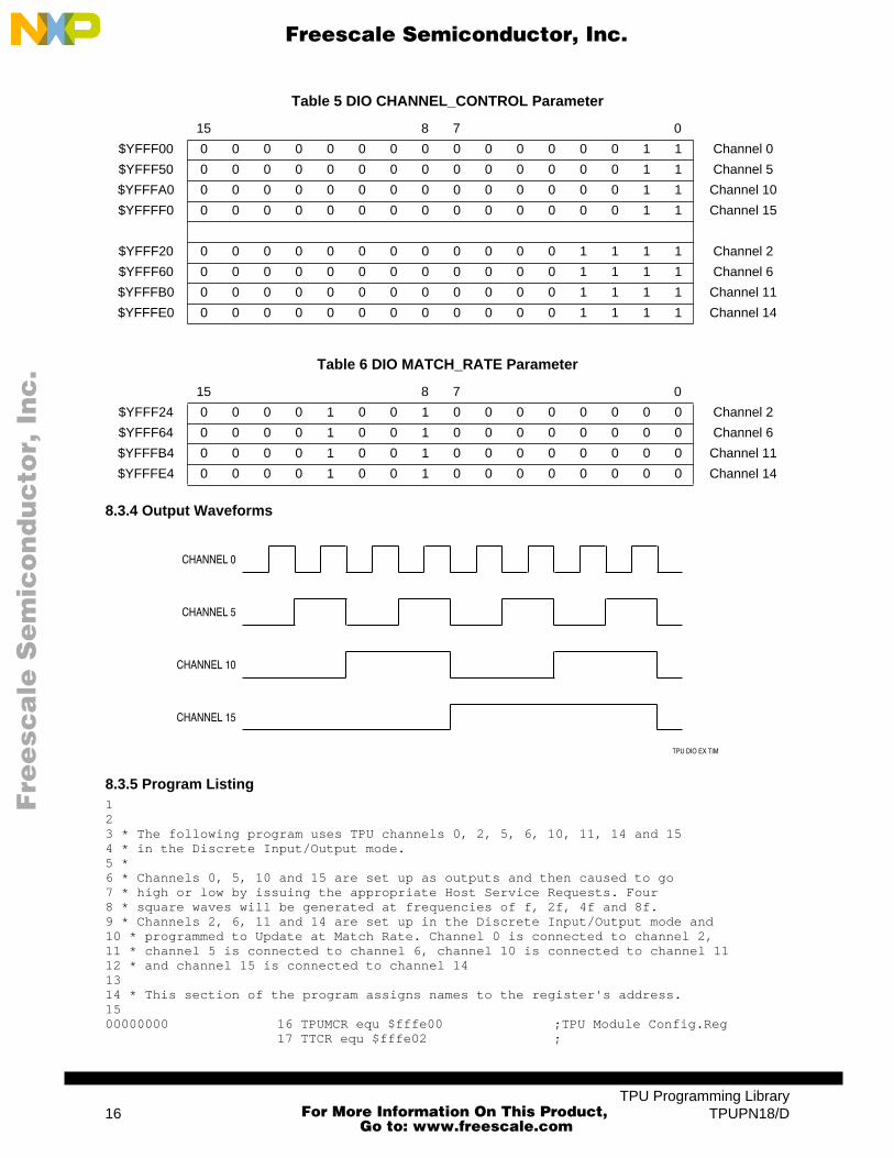
This program uses TPU channels 0, 2, 5, 6, 10, 11, 14, and 15 with the discrete output function. Theprogram sets up channels 0, 5, 10, and 15 as outputs and then causes them to go high or low by issuingthe appropriate host service requests. Four square waves are generated at frequencies of f, 2f, 4f, and8f. In addition, TPU channels 2, 6, 11, and 14 are configured as inputs and programmed to update atmatch rate. Channel 0 drives channel 2, channel 5 drives channel 6, channel 10 drives channel 11, andchannel 16 drives channel 14.
8.3.2 Hardware Configuration
8.3.3 Initialization
Configure the CHANNEL_CONTROL and MATCH_RATE registers as follows:
TPU DIO EX CONN
CHANNEL 0
CHANNEL 2
CHANNEL 5
CHANNEL 6
CHANNEL 10
CHANNEL 11
CHANNEL 14
CHANNEL 15
TPU
TPU Programming LibraryTPUPN18/D 15
For More Information On This Product,
Go to: www.freescale.com
Fre
esc
ale
Se
mic
on
du
cto
r, I
Freescale Semiconductor, Inc.n
c..
.
8.3.4 Output Waveforms
8.3.5 Program Listing1 2 3 * The following program uses TPU channels 0, 2, 5, 6, 10, 11, 14 and 154 * in the Discrete Input/Output mode.5 * 6 * Channels 0, 5, 10 and 15 are set up as outputs and then caused to go7 * high or low by issuing the appropriate Host Service Requests. Four 8 * square waves will be generated at frequencies of f, 2f, 4f and 8f.9 * Channels 2, 6, 11 and 14 are set up in the Discrete Input/Output mode and10 * programmed to Update at Match Rate. Channel 0 is connected to channel 2,11 * channel 5 is connected to channel 6, channel 10 is connected to channel 1112 * and channel 15 is connected to channel 1413 14 * This section of the program assigns names to the register's address.15 00000000 16 TPUMCR equ $fffe00 ;TPU Module Config.Reg
17 TTCR equ $fffe02 ;
Table 5 DIO CHANNEL_CONTROL Parameter
15 8 7 0
$YFFF00 0 0 0 0 0 0 0 0 0 0 0 0 0 0 1 1 Channel 0
$YFFF50 0 0 0 0 0 0 0 0 0 0 0 0 0 0 1 1 Channel 5
$YFFFA0 0 0 0 0 0 0 0 0 0 0 0 0 0 0 1 1 Channel 10
$YFFFF0 0 0 0 0 0 0 0 0 0 0 0 0 0 0 1 1 Channel 15
$YFFF20 0 0 0 0 0 0 0 0 0 0 0 0 1 1 1 1 Channel 2
$YFFF60 0 0 0 0 0 0 0 0 0 0 0 0 1 1 1 1 Channel 6
$YFFFB0 0 0 0 0 0 0 0 0 0 0 0 0 1 1 1 1 Channel 11
$YFFFE0 0 0 0 0 0 0 0 0 0 0 0 0 1 1 1 1 Channel 14
Table 6 DIO MATCH_RATE Parameter
15 8 7 0
$YFFF24 0 0 0 0 1 0 0 1 0 0 0 0 0 0 0 0 Channel 2
$YFFF64 0 0 0 0 1 0 0 1 0 0 0 0 0 0 0 0 Channel 6
$YFFFB4 0 0 0 0 1 0 0 1 0 0 0 0 0 0 0 0 Channel 11
$YFFFE4 0 0 0 0 1 0 0 1 0 0 0 0 0 0 0 0 Channel 14
CHANNEL 0
CHANNEL 5
CHANNEL 10
CHANNEL 15
TPU DIO EX TIM
TPU Programming Library16 TPUPN18/D
For More Information On This Product,
Go to: www.freescale.com

Fre
esc
ale
Se
mic
on
du
cto
r, I
Freescale Semiconductor, Inc.n
c..
.
00000000 18 DSCR equ $fffe04 ;00000000 19 DSSR equ $fffe06 ;00000000 20 TICR equ $fffe08 ;Interrupt Config Reg 00000000 21 CIER equ $fffe0a ;Ch. Int. Enable Reg00000000 22 CFSR0 equ $fffe0c ;TPU Ch Function Select Reg 000000000 23 CFSR1 equ $fffe0e ;TPU Ch Funct Select Reg 100000000 24 CFSR2 equ $fffe10 ;TPU Ch Funct Select Reg 200000000 25 CFSR3 equ $fffe12 ;TPU Ch Funct Select Reg 300000000 26 HSQR0 equ $fffe14 ;Host Sequence Reg 000000000 27 HSQR1 equ $fffe16 ;Host Sequence Reg 100000000 28 HSRR0 equ $fffe18 ;Host Service Req. Reg 000000000 29 HSRR1 equ $fffe1a ;Host Service Req. Reg 100000000 30 CPR0 equ $fffe1c ;Ch. Priority Reg 000000000 31 CPR1 equ $fffe1e ;Ch Priority Re 100000000 32 CISR equ $fffe20 ;Interrupt Status Reg00000000 33 CH0_CNTL equ $ffff00 ;Ch. 0 Control Reg00000000 34 CH0_PINL equ $ffff02 ;Ch. 0 Pin Level Reg00000000 35 CH0_MATCH equ $ffff04 ;Ch 0 Match Rate Reg00000000 36 CH2_CNTL equ $ffff20 ;Ch 2 Control Reg00000000 37 CH2_PINL equ $ffff22 ;Ch 2 Pin Level Reg00000000 38 CH2_MATCH equ $ffff24 ;Ch 2 Match Rate Reg00000000 39 CH5_CNTL equ $ffff50 ;Ch 5 Control Reg00000000 40 CH5_PINL equ $ffff52 ;Ch 5 Pin Level Reg00000000 41 CH5_MATCH equ $ffff54 ;Ch 5 Match Rate Reg00000000 42 CH6_CNTL equ $ffff60 ;Ch 6 Control Reg00000000 43 CH6_PINL equ $ffff62 ;Ch 6 Pin Level Reg00000000 44 CH6_MATCH equ $ffff64 ;Ch 6 Match Rate Reg00000000 45 CH10_CNTL equ $ffffa0 ;Ch 10 Control Reg00000000 46 CH10_PINL equ $ffffa2 ;Ch 10 Pin Level Reg00000000 47 CH10_MATCH equ $ffffa4 ;Ch 10 Match Rate Reg00000000 48 CH11_CNTL equ $ffffb0 ;Ch 11 Control Reg00000000 49 CH11_PINL equ $ffffb2 ;Ch 11 Pin Level Reg00000000 50 CH11_MATCH equ $ffffb4 ;Ch 11 Match Rate Reg00000000 51 CH14_CNTL equ $ffffe0 ;Ch 14 Control Reg00000000 52 CH14_PINL equ $ffffe2 ;Ch 14 Pin Level Reg00000000 53 CH14_MATCH equ $ffffe4 ;Ch 14 Match Rate Reg00000000 54 CH15_CNTL equ $fffff0 ;Ch 15 Control Reg00000000 55 CH15_PINL equ $fffff2 ;Ch 15 Pin Level Reg00000000 56 CH15_MATCH equ $fffff4 ;Ch 15 Match Rate Reg
57 00005000 58 org $5000 ;program origin59 * This portion of the program initializes the TPU reg59 00005000 33FC8800 60 init move.w #$8800,(CFSR0).l ;init ch 1,5,14 to DIO
00FFFE0C 00005008 33FC8800 61 move.w #$8800,(CFSR1).l ;init ch 10,11 to DIO
00FFFE0E 00005010 33FC0880 62 move.w #$0880,(CFSR2).l ;init ch,6 to DIO
00FFFE10 00005018 33FC0808 63 move.w #$0808,(CFSR3).l ;init ch 0,2 to DIO
00FFFE12 00005020 33FC1040 64 move.w #$1040,(HSQR0).l ;ch. 15,10 pin level
00FFFE14 ;update on transition65 ;ch. 14,11 update at
;match rate00005028 33FC1010 66 move.w #$1010,(HSQR1).l ;ch. 5,0 pin level
00FFFE16 ;update on transition67 ;ch. 2 and 6 update at
;match rate00005030 33FCF0F0 68 move.w #$f0f0,(CPR0).l ;ch. 15,14,10,11 have
00FFFE1C ;high priority00005038 33FC3C33 69 move.w #$3c33,(CPR1).l ;ch. 5,6 and 2,0 have
00FFFE1E ;high priority00005040 33FC0003 70 move.w #$0003,(CH15_CNTL).l;ch. 15 use TCR1
00FFFFF0 00005048 33FC000F 71 move.w #$000f,(CH14_CNTL).l;ch. 14 use TCR1
TPU Programming LibraryTPUPN18/D 17
For More Information On This Product,
Go to: www.freescale.com

Fre
esc
ale
Se
mic
on
du
cto
r, I
Freescale Semiconductor, Inc.n
c..
.
00FFFFE0 ;detect both edges00005050 33FC0900 72 move.w #$0900,(CH14_MATCH).l;ch.14 match-$900
00FFFFE4 00005058 33FC000F 73 move.w #$000f,(CH11_CNTL).l;ch. 11 use TCR1,
00FFFFB0 ;detect both edges00005060 33FC0900 74 move.w #$0900,(CH11_MATCH).l;ch. 11 match-$900
00FFFFB4 00005068 33FC0003 75 move.w #$0003,(CH10_CNTL).l ;ch. 10 use TCR1
00FFFFA0 00005070 33FC000F 76 move.w #$000f,(CH6_CNTL).l ;ch. 6 use TCR1
00FFFF60 ;detect both edges00005078 33FC0900 77 move.w #$0900,(CH6_MATCH).l ;ch. 6 match-$900
00FFFF64 00005080 33FC0003 78 move.w #$0003,(CH5_CNTL).l ;ch. 5 use TCR1
00FFFF50 00005088 33FC000F 79 move.w #$000f,(CH2_CNTL).l ;ch. 2 use TCR1
00FFFF20 ;detect both edges00005090 33FC0900 80 move.w #$0900,(CH2_MATCH).l ;ch. 2 match-$900
00FFFF24 00005098 33FC0003 81 move.w #$0003,(CH0_CNTL).l ;ch. 0 use TCR1
00FFFF00 82
83 * This portion of the program initializes the DIO channels as inputs and84 * outputs as specified. No action85 * will be taken on an external pin by executing the next two instructions.
86 000050A0 33FCF0F0 87 move.w #$f0f0,(HSRR0).l ;HSR to init ch.
00FFFE18 ;15,14,11,10000050A8 33FC3C33 88 move.w #$3c33,(HSRR1).l ;HSR to init ch. 5,6,2,0
00FFFE1A89
90 * This portion of the program generates four square waves using software91 * timing loops.
92 000050B0 33FC8020 93 strt move.w #$8020,(HSRR0).l ;HSR - ch. 15 - lo, c
00FFFE18 000050B8 33FC0802 93 move.w #$0802,(HSRR1).l ;HSR-ch 5-lo,ch 0-lo
00FFFE1A 000050C0 4EB85194 94 jsr wait000050C4 33FC0001 95 move.w #$0001,(HSRR1).l ;HSR - ch. 0 - hi
00FFFE1A 000050CC 4EB85194 96 jsr wait000050D0 33FC0402 97 move.w #$0402,(HSRR1).l ;HSR-ch. 5-hi, ch 0-lo
00FFFE1A 000050D8 4EB85194 98 jsr wait000050DC 33FC0001 99 move.w #$0001,(HSRR1).l ;HSR-ch. 5-hi, ch - hi
00FFFE1A 000050E4 4EB85194 100 jsr wait000050E8 33FC0802 101 move.w #$0802,(HSRR1).l ;HSR-ch. 5-lo, ch 0 lo
00FFFE1A 000050F0 33FC0010 102 move.w #$0010,(HSRR0).l ;HSR-ch. 15-lo, c
00FFFE18 000050F8 4EB85194 102 jsr wait000050FC 33FC0001 103 move.w #$0001,(HSRR1).l ;HSR-ch. 5-lo, ch 0-hi
00FFFE1A 00005104 4EB85194 104 jsr wait00005108 33FC0402 105 move.w #$0402,(HSRR1).l ;HSR-ch. 5-hi, ch 0-l0
00FFFE1A 00005110 4EB85194 106 jsr wait00005114 33FC0001 107 move.w #$0001,(HSRR1).l ;HSR-ch. 5-hi, ch 0-hi
00FFFE1A 0000511C 4EB85194 108 jsr wait00005120 33FC0802 109 move.w #$0802,(HSRR1).l ;HSR-ch. 5-lo, ch 0-lo
00FFFE1A 00005128 33FC4020 110 move.w #$4020,(HSRR0).l ;HSR-ch. 15-hi, c
00FFFE18
TPU Programming Library18 TPUPN18/D
For More Information On This Product,
Go to: www.freescale.com

Fre
esc
ale
Se
mic
on
du
cto
r, I
Freescale Semiconductor, Inc.n
c..
.
00005130 4EB85194 110 jsr wait00005134 33FC0001 111 move.w #$0001,(HSRR1).l ;HSR-ch. 5-lo, ch 0-hi
00FFFE1A 0000513C 4EB85194 112 jsr wait00005140 33FC0402 113 move.w #$0402,(HSRR1).l ;HSR-ch. 5-hi, ch 0-lo
00FFFE1A 00005148 4EB85194 114 jsr wait0000514C 33FC0001 115 move.w #$0001,(HSRR1).l ;HSR-ch 5-hi, ch 0-hi
00FFFE1A 00005154 4EB85194 116 jsr wait00005158 33FC0802 117 move.w #$0802,(HSRR1).l ;HSR-ch. 5-lo, ch 0-lo
00FFFE1A 00005160 33FC0010 118 move.w #$0010,(HSRR0).l ;HSR - ch. 15 - hi, c
00FFFE18 00005168 4EB85194 118 jsr wait0000516C 33FC0001 119 move.w #$0001,(HSRR1).l ;HSR-ch. 5-lo, ch 0-hi
00FFFE1A 00005174 4EB85194 120 jsr wait00005178 33FC0402 121 move.w #$0402,(HSRR1).l ;HSR-ch. 5-hi, ch 0-lo
00FFFE1A 00005180 4EB85194 122 jsr wait00005184 33FC0001 123 move.w #$0001,(HSRR1).l ;HSR-ch. 5-hi, ch 0-lo
00FFFE1A 0000518C 4EB85194 124 jsr wait00005190 4EF850B0 125 jmp strt00005194 203C0000 126 waitmove.l #$fff,d0 ;wait loop
0FFF 0000519A 90BC0000 127 lop1sub.l #$1,d0 ;wait loop
0001 000051A0 6600FFF8 128 bne lop1 ;wait loop000051A4 383900FF 129 move.w ($ffff22).l,d4 ;ch 2 match rate reg FF22
;to D4000051AA 3A3900FF 130 move.w ($ffff62).l,d5 ;ch 6 match rate reg FF62
; in D5000051B0 3C3900FF 131 move.w ($ffffb2).l,d6 ;ch 11 match rate reg FFB2
;to D11000051B6 3E3900FF 132 move.w ($ffffe2).l,d7 ;ch 14 match rate reg FFE2
;to D14000051BC 4E75 133 rts
134
9 Function State DescriptionsThis section describes the states entered for each of the four DIO cases (request for initialization, up-date on match rate, update on transition, and set pin low or high). Refer to 10 Function Algorithm fordetailed descriptions of each state.
A host service request can be issued at any time and from any state. To begin, assume that the channelfunction select register, host sequence register, channel priority register and the channel parameterRAM have all been programmed. At this point the channel will be ready to receive its first host servicerequest via the host service request register.
9.1 CASE 1: Request for InitializationHSR = 11, INITIALIZATIONHSQ = 10, UPDATE ON HSR = 11
State 1 is entered. The channel pin is not configured as an output or an input; it is simply left in its currentcondition. The contents of the PIN_LEVEL register are shifted to the right by one bit and the new pinstate is recorded in bit 15 of the PIN_LEVEL register. Out of reset, the TPU channel pins are inputs. Ingeneral, a TPU channel could be either an input or an output. The level that is written into bit 15 of thePIN_LEVEL register will either be the level driven into the TPU channel if the channel is currently con-figured as an input or the level being driven by the TPU channel if the channel is configured as an out-put.
TPU Programming LibraryTPUPN18/D 19
For More Information On This Product,
Go to: www.freescale.com
Fre
esc
ale
Se
mic
on
du
cto
r, I
Freescale Semiconductor, Inc.n
c..
.
It is most important to recognize that for the case being discussed, i.e., the HSR bits = 11 (initialization)and the HSQ bits = 10 (mode 2), the S1 state is simply executed, exited, and no further action is taken.Realize that S2, S3 and S4 cannot be entered unless the algorithm is currently in S1. Therefore, theHSQ bits cannot be equal to %10 if a channel is to be configured as an input and sampled at the matchrate or on each transition.
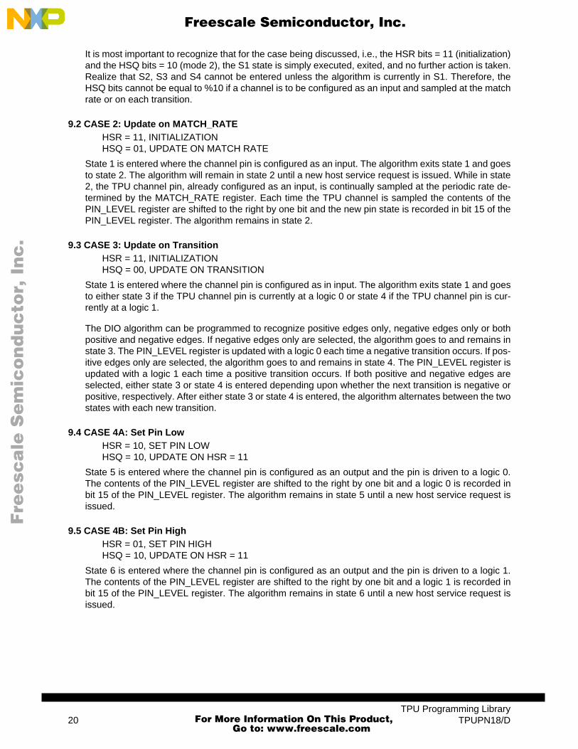
9.2 CASE 2: Update on MATCH_RATEHSR = 11, INITIALIZATIONHSQ = 01, UPDATE ON MATCH RATE
State 1 is entered where the channel pin is configured as an input. The algorithm exits state 1 and goesto state 2. The algorithm will remain in state 2 until a new host service request is issued. While in state2, the TPU channel pin, already configured as an input, is continually sampled at the periodic rate de-termined by the MATCH_RATE register. Each time the TPU channel is sampled the contents of thePIN_LEVEL register are shifted to the right by one bit and the new pin state is recorded in bit 15 of thePIN_LEVEL register. The algorithm remains in state 2.
9.3 CASE 3: Update on TransitionHSR = 11, INITIALIZATIONHSQ = 00, UPDATE ON TRANSITION
State 1 is entered where the channel pin is configured as in input. The algorithm exits state 1 and goesto either state 3 if the TPU channel pin is currently at a logic 0 or state 4 if the TPU channel pin is cur-rently at a logic 1.
The DIO algorithm can be programmed to recognize positive edges only, negative edges only or bothpositive and negative edges. If negative edges only are selected, the algorithm goes to and remains instate 3. The PIN_LEVEL register is updated with a logic 0 each time a negative transition occurs. If pos-itive edges only are selected, the algorithm goes to and remains in state 4. The PIN_LEVEL register isupdated with a logic 1 each time a positive transition occurs. If both positive and negative edges areselected, either state 3 or state 4 is entered depending upon whether the next transition is negative orpositive, respectively. After either state 3 or state 4 is entered, the algorithm alternates between the twostates with each new transition.
9.4 CASE 4A: Set Pin LowHSR = 10, SET PIN LOWHSQ = 10, UPDATE ON HSR = 11
State 5 is entered where the channel pin is configured as an output and the pin is driven to a logic 0.The contents of the PIN_LEVEL register are shifted to the right by one bit and a logic 0 is recorded inbit 15 of the PIN_LEVEL register. The algorithm remains in state 5 until a new host service request isissued.
9.5 CASE 4B: Set Pin HighHSR = 01, SET PIN HIGHHSQ = 10, UPDATE ON HSR = 11
State 6 is entered where the channel pin is configured as an output and the pin is driven to a logic 1.The contents of the PIN_LEVEL register are shifted to the right by one bit and a logic 1 is recorded inbit 15 of the PIN_LEVEL register. The algorithm remains in state 6 until a new host service request isissued.
TPU Programming Library20 TPUPN18/D
For More Information On This Product,
Go to: www.freescale.com

Fre
esc
ale
Se
mic
on
du
cto
r, I
Freescale Semiconductor, Inc.n
c..
.
10 Function AlgorithmThe DIO time function consists of six states, described in the following paragraphs. The following de-scription is provided as a guide only, to aid understanding of the function. The exact sequence of oper-ations in microcode may be different from that shown, in order to optimize speed and code size. TPUmicrocode source listings for all functions in the TPU function library can be downloaded from the Mo-torola Freeware bulletin board. Refer to Using the TPU Function Library and TPU Emulation Mode(TPUPN00/D) for detailed instructions on downloading and compiling microcode.
10.1 State 1: InitRecord_PS
Condition: HSR1, HSR0, M/TSR, LSR, Pin, Flag0 = 11xxxx
Match Enable: Don't Care A.1.1 State 1 Init/Record_PS
Summary:This state is entered as a result of HSR %11. In this state the channel is either configured to performmodes 1 or 2 discrete input or, if host sequence equals 10, the channel is not configured and thepin state is recorded in bit 15 of PIN_LEVEL. The previous pin states are shifted right by one, losingthe least recent pin state in bit 0. An interrupt request is then generated. Flag0 is used internally toindicate one of two modes of operation when configured for discrete input. When clear, flag0 indi-cates transition mode operation; when set, it indicates match mode operation.
If host sequence bit 1 = 1 {Bit N replaced by bit N+1 of parameter PLVBit 15 of parameter PLV gets pin stateAssert interrupt request
}Else {
Configure the channel latches via CHANNEL_CONTROL Clear flag0ERT replaced by TCR1If host sequence bit 0 = 0 {
Bit N replaced by bit N+1 of parameter PLVBit 15 of parameter PLV gets pin stateAssert interrupt request
}Else {
Generate match at ERT + MATCH_RATEAssert flag0Bit N replaced by bit N+1 of parameter PLVBit 15 of parameter PLV gets pin stateAssert interrupt request
}}
10.1.1 State 2: Match_PS
Condition: HSR1, HSR0, M/TSR, LSR, Pin, Flag0 = 001xx1
Match Enable: Disable
Summary:This state is entered due to a match when the channel is configured for discrete input match modeoperation. In this state a new match time is scheduled by adding the last match time toMATCH_RATE. Bit 15 of PIN_LEVEL is updated with the pin level recorded at the time of service,and the previous pin states are shifted right by one, losing the least recent pin state contained in bit0. An interrupt request is then generated.
TPU Programming LibraryTPUPN18/D 21
For More Information On This Product,
Go to: www.freescale.com

Fre
esc
ale
Se
mic
on
du
cto
r, I
Freescale Semiconductor, Inc.n
c..
.
Generate match at ERT + MATCH_RATEBit N replaced by bit N+1 of parameter PLVBit 15 of parameter PLV gets pin stateNegate MRL, TDL, LSRAssert interrupt request
10.1.2 State 3: Trans_PS_Low
Condition: HSR1, HSR0, M/TSR, LSR, Pin, Flag0 = 001x00
Match Enable: Don't Care
Summary:This state is entered in transition mode only, after a transition is detected, when the pin is low at thetime of service. Bit 15 of PIN_LEVEL is updated with the pin level, and the previous pin states areshifted right by one, losing the least recent pin state contained in bit 0. An interrupt request is thengenerated.
Bit N replaced by bit N+1 of parameter PLVBit 15 of parameter PLV gets pin state 0Negate MRL, TDL, LSRAssert interrupt request
10.1.3 State 4: Trans_PS_High
Condition: HSR1, HSR0, M/TSR, LSR, Pin, Flag0 = 001x10
Match Enable: Don't Care
Summary:This state is entered in transition mode only, after a transition is detected, when the pin is high atthe time of service. Bit 15 of PIN_LEVEL is updated with the pin level, and the previous pin statesare shifted right by one, losing the least recent pin state contained in bit 0. An interrupt request isthen generated.
Bit N replaced by bit N+1 of parameter PLVBit 15 of parameter PLV gets pin state 1Negate MRL, TDL, LSRAssert interrupt request
10.1.4 State 5: Low_Pin_Request
Condition: HSR1, HSR0, M/TSR, LSR, Pin, Flag0 = 10xxxx
Match Enable: Don't Care
Summary:This state is entered due to HSR %10. In this state the pin becomes an output and is forced low,and the match and capture time bases are forced to TCR1. Bit 15 of PIN_LEVEL is updated withthe pin level, which is forced, and the previous pin states are shifted right by one, losing the leastrecent pin state contained in bit 0. An interrupt request is then generated.
Set pin lowBit N replaced by bit N+1 of parameter PLVBit 15 of parameter PLV gets pin state 0Negate MRL, TDL, LSRAssert interrupt request
TPU Programming Library22 TPUPN18/D
For More Information On This Product,
Go to: www.freescale.com
Fre
esc
ale
Se
mic
on
du
cto
r, I
Freescale Semiconductor, Inc.n
c..
.
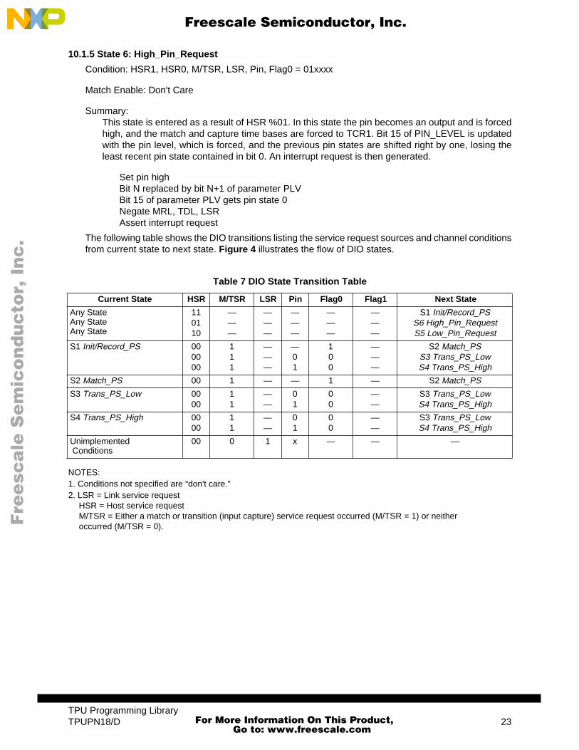
10.1.5 State 6: High_Pin_Request
Condition: HSR1, HSR0, M/TSR, LSR, Pin, Flag0 = 01xxxx
Match Enable: Don't Care
Summary:This state is entered as a result of HSR %01. In this state the pin becomes an output and is forcedhigh, and the match and capture time bases are forced to TCR1. Bit 15 of PIN_LEVEL is updatedwith the pin level, which is forced, and the previous pin states are shifted right by one, losing theleast recent pin state contained in bit 0. An interrupt request is then generated.
Set pin highBit N replaced by bit N+1 of parameter PLVBit 15 of parameter PLV gets pin state 0Negate MRL, TDL, LSRAssert interrupt request
The following table shows the DIO transitions listing the service request sources and channel conditionsfrom current state to next state. Figure 4 illustrates the flow of DIO states.
NOTES:1. Conditions not specified are “don't care.”2. LSR = Link service request
HSR = Host service request M/TSR = Either a match or transition (input capture) service request occurred (M/TSR = 1) or neither occurred (M/TSR = 0).
Table 7 DIO State Transition Table
Current State HSR M/TSR LSR Pin Flag0 Flag1 Next State
Any StateAny StateAny State
110110
———
———
———
———
———
S1 Init/Record_PSS6 High_Pin_RequestS5 Low_Pin_Request
S1 Init/Record_PS 000000
111
———
—01
100
———
S2 Match_PSS3 Trans_PS_LowS4 Trans_PS_High
S2 Match_PS 00 1 — — 1 — S2 Match_PS
S3 Trans_PS_Low 0000
11
——
01
00
——
S3 Trans_PS_LowS4 Trans_PS_High
S4 Trans_PS_High 0000
11
——
01
00
——
S3 Trans_PS_LowS4 Trans_PS_High
Unimplemented Conditions
00 0 1 x — — —
TPU Programming LibraryTPUPN18/D 23
For More Information On This Product,
Go to: www.freescale.com

F
ree
sca
le S
em
ico
nd
uc
tor,
I
Freescale Semiconductor, Inc.n
c..
.
Figure 4 DIO State Flowchart
001XX1
S2MATCH_PS
1018A
OUTPUT LOWHSR = 10
MATCH RATEM/T = 1
FLAG0 = 1(MODE 1)
TRANSITIONM/T = 1PIN = 0
FLAG0 = 0(MODE 0)
M/T = 1PIN = 1
FLAG0 = 0
MATCHM/T = 1PIN = 0
FLAG0 = 0
MATCHM/T= 1
FLAG0 = 1
INPUTHSR = 11
MODE 2
EXIT
KEY:
HSR M/TSR LSR PIN FLAG0 FLAG1XX X X X X X
ANY STATE
11XXXX
S1INIT/RECORD_PS
01XXXX
S5LOW_PIN_REQUEST
10XXXX
S6HI_PIN_
REQUEST
001X00
S3TRANS_PS_
LOW
001X10
S4TRANS_PS_
HI
OUTPUT HIGHHSR = 01
TRANSITIONM/T = 1PIN = 1
FLAG0 = 0 (MODE 0)
M/T = 1PIN = 0
FLAG0 = 0
MATCHM/T = 1PIN = 1
FLAG0 = 0
For More Information On This Product,
Go to: www.freescale.com