disconnect switches - itc electrical components · disconnect switches disconnect switches are...
TRANSCRIPT


Disconnect Switches
Disconnect Switches are control devices used to turn power “ON-OFF” on most machines, control panels, HVAC equipment. Many models feature a lockout to prevent unauthorized use. These switches are available in door mount, panel mount, DIN rail mount and fully enclosed, and in models rated from 16A to 250A (UL general use rating), in 3, 4 and 6 poles versions. All ITC by Sontheimer switches have UL and CSA approvals. The compact LO series of switches range from 16A to 63A, and NT series of disconnects from 63A to 250A. Rotary switches from Sontheimer in all configurations are available, upon special request.
Index
UL Ratings .................................................................................................................... 3 Door mount disconnect switches 4 hole mounting type “E” ......................................................... 4 Door mount disconnect switches central hole mounting type “ZM” ............................................... 5 DIN rail mount disconnect switches 4 Hole mounting type “T” ..................................................... 6 Panel mount disconnect switches type “V” ............................................................................ 7 Schematic diagrams of Type “E”, “ZM”, “PM” and “V” disconnect switches .................................... 9 Enclosed disconnect switches types RLO/RLT ........................................................................ 10 MINI25 - Compact Enclosed Disconnect Switch 25A ................................................................. 11 Accessories for disconnect switches ................................................................................... 12 Voltmeter and ammeter switches ...................................................................................... 17 DC disconnect switches................................................................................................... 18
2

UL Ratings All Sontheimer disconnect switches are suitable for use as a motor disconnect. NLO & RLO Disconnect Switches
Size General Use Rating Motor Rating (UL, CSA)
HP HP 1 Phase 3 Phase 1 Phase 3 Phase 0 – 240V
0 – 600V
120V 240V 120V 240V 480V 600V
16 16A 16A 0.5 1.5 1 3 7.5 10 25 25A 25A 2 3 3 7.5 10 15 32 32A 32A 2 3 3 10 20 22 40 40A 32A 2 4 5 10 20 20 63 50A 32A 3 10 5 15 25 30
Wire gauge for all above models is 14-6 AWG. Short circuit rating for all the above is 5kA. Tightening torque for all the above is 3.0 Nm. Information subject to change without notice
NLT & RLT Disconnect Switches
Size General Use
Rating 3 Phase 0-600V
Wire Range Motor Rating (UL, CSA)
Short Circuit Rating
HP 3 Phase
AWG mm2 240V 480V 600V 63 63A 18 - 10 1 – 6 ◊ 15 40 50 80 63A 18 - 10 1 – 6 ◊ 15 40 50 100 100A 12 – 1 4 – 50 □ 30 60 75 125 125A 12 – 1 4 – 50 □ 40 75 100 180 180A 1/0–3/0 50 – 95 □ 40 75 50 250 250A 250-400 MCM 127-202 □ 50 100 75
◊ 5 kA short circuit rating at 600V, when protected by 175A RK5 fuse or by a combination motor controller rated maximum 50hp at 600Vac. □ 10KA short circuit rating at 600V, when protected by 200A class RK5 fuse. Tightening torque for 63 to 125 is 3.0 Nm, for 180 & 250 is 10.0 Nm. Information subject to change without notice
3
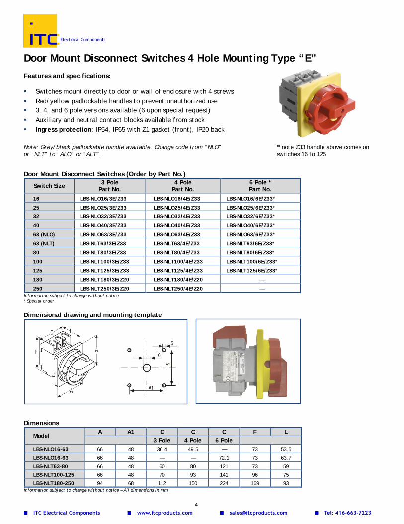
Door Mount Disconnect Switches 4 Hole Mounting Type “E” Features and specifications: Switches mount directly to door or wall of enclosure with 4 screws Red/yellow padlockable handles to prevent unauthorized use 3, 4, and 6 pole versions available (6 upon special request) Auxiliary and neutral contact blocks available from stock Ingress protection: IP54, IP65 with Z1 gasket (front), IP20 back Note: Grey/black padlockable handle available. Change code from “NLO” * note Z33 handle above comes on or “NLT” to “ALO” or “ALT”. switches 16 to 125
Door Mount Disconnect Switches (Order by Part No.)
Switch Size 3 Pole Part No.
4 Pole Part No.
6 Pole * Part No.
16 LBS-NLO16/3E/Z33 LBS-NLO16/4E/Z33 LBS-NLO16/6E/Z33*
25 LBS-NLO25/3E/Z33 LBS-NLO25/4E/Z33 LBS-NLO25/6E/Z33*
32 LBS-NLO32/3E/Z33 LBS-NLO32/4E/Z33 LBS-NLO32/6E/Z33*
40 LBS-NLO40/3E/Z33 LBS-NLO40/4E/Z33 LBS-NLO40/6E/Z33*
63 (NLO) LBS-NLO63/3E/Z33 LBS-NLO63/4E/Z33 LBS-NLO63/6E/Z33*
63 (NLT) LBS-NLT63/3E/Z33 LBS-NLT63/4E/Z33 LBS-NLT63/6E/Z33*
80 LBS-NLT80/3E/Z33 LBS-NLT80/4E/Z33 LBS-NLT80/6E/Z33*
100 LBS-NLT100/3E/Z33 LBS-NLT100/4E/Z33 LBS-NLT100/6E/Z33*
125 LBS-NLT125/3E/Z33 LBS-NLT125/4E/Z33 LBS-NLT125/6E/Z33*
180 LBS-NLT180/3E/Z20 LBS-NLT180/4E/Z20 —
250 LBS-NLT250/3E/Z20 LBS-NLT250/4E/Z20 — Information subject to change without notice * Special order
Dimensional drawing and mounting template
Dimensions
Model A A1 C C C F L
3 Pole 4 Pole 6 Pole
LBS-NLO16-63 66 48 36.4 49.5 — 73 53.5
LBS-NLO16-63 66 48 — — 72.1 73 63.7
LBS-NLT63-80 66 48 60 80 121 73 59
LBS-NLT100-125 66 48 70 93 141 96 75
LBS-NLT180-250 94 68 112 150 224 169 93 Information subject to change without notice – All dimensions in mm
4

Door Mount Disconnect Switches Central Hole Mounting Type “ZM”
Features and specifications:
Switches mount directly to door of enclosure through a single 22.5mm diameter, notched hole
Red/yellow padlockable handles to prevent unauthorized use 3 pole versions available from stock. 4 and 6 pole upon request Auxiliary and neutral contact blocks available Ingress protection: IP54, IP65 with gasket Z1 (front), IP20 back Note: Grey/black padlockable handle available. Change code from “NLO” or “NLT” to “ALO” or “ALT”
Z20 handle pictured above
“ZM” Door Mount Disconnect Switches (Order by Part No.)
Switch Size 3 Pole Z20 Part No.
4 Pole Z20 Part No.*
3 Pole Z33 Part No.
4 Pole Z33 Part No.*
16 LBS-NLO16/3ZM/Z20 LBS-NLO16/4ZM/Z20* LBS-NLO16/3ZM/Z33 LBS-NLO16/4ZM/Z33*
25 LBS-NLO25/3ZM/Z20 LBS-NLO25/4ZM/Z20* LBS-NLO25/3ZM/Z33 LBS-NLO25/4ZM/Z33*
32 LBS-NLO32/3ZM/Z20 LBS-NLO32/4ZM/Z20* LBS-NLO32/3ZM/Z33 LBS-NLO32/4ZM/Z33*
40 LBS-NLO40/3ZM/Z20 LBS-NLO40/4ZM/Z20* LBS-NLO40/3ZM/Z33 LBS-NLO40/4ZM/Z33*
63 (NLO) LBS-NLO63/3ZM/Z20 LBS-NLO63/4ZM/Z20* LBS-NLO63/3ZM/Z33 LBS-NLO63/4ZM/Z33*
63 (NLT) LBS-NLT63/3ZM/Z20 LBS-NLT63/4ZM/Z20* LBS-NLT63/3ZM/Z33 LBS-NLT63/4ZM/Z33*
80 LBS-NLT80/3ZM/Z20 LBS-NLT80/4ZM/Z20* LBS-NLT80/3ZM/Z33 LBS-NLT80/4ZM/Z33* Information subject to change without notice * Special order Dimensional drawing and mounting template
Dimensions
Z33 Handle Z20 Handle
Model A C C F L A C C F L
3 Pole 4 Pole 3 Pole 4 Pole
LBS-NLO16-63 66 36 49.5 73 76 48.5 36 49.5 73 77
LBS-NLT63-80 66 60 80 83 84 — — — — — Information subject to change without notice – All dimensions in mm
5

DIN Rail Mount Disconnect Switches Type “T” Features and specifications: Switches mount directly on DIN Rail Red/yellow padlockable handles to prevent unauthorized use 3, 4, and 6 pole versions available (6 pole upon special request) Auxiliary and additional contact blocks available from stock Face plate hinged to allow access to screws without removing handle and face plate Ingress protection: IP20 DIN Rail Mount Disconnect Switches Direct Mount Handle – Type T (Order by Part No.)
Switch Size 3 Pole Part No.
4 Pole Part No.
6 Pole Part No.*
16 LBS-NLO16/3T/Z20 LBS-NLO16/4T/Z20 LBS-NLO16/6T/Z20*
25 LBS-NLO25/3T/Z20 LBS-NLO25/4T/Z20 LBS-NLO25/6T/Z20*
32 LBS-NLO32/3T/Z20 LBS-NLO32/4T/Z20 LBS-NLO32/6T/Z20*
40 LBS-NLO40/3T/Z20 LBS-NLO40/4T/Z20 LBS-NLO40/6T/Z20*
63 (NLO) LBS-NLO63/3T/Z20 LBS-NLO63/4T/Z20 LBS-NLO63/6T/Z20*
63 (NLT) LBS-NLT63/3T/Z20 LBS-NLT63/4T/Z20 LBS-NLT63/6T/Z20*
80 LBS-NLT80/3T/Z20 LBS-NLT80/4T/Z20 LBS-NLT80/6T/Z20*
100 LBS-NLT100/3T/Z20 LBS-NLT100/4T/Z20 LBS-NLT100/6T/Z20*
125 LBS-NLT125/3T/Z20 LBS-NLT125/4T/Z20 LBS-NLT125/6T/Z20* Information subject to change without notice * Special order
Dimensions
Model A A A C C C F
3 Pole 4 Pole 6 Pole 3 Pole 4 Pole 6 Pole LBS-NLO16-63 36 36 79 36 49 72 60
LBS-NLT63-80 63 83 125 60 82 121 64
LBS-NLT100-125 70 93 140 70 93 141 83 Information subject to change without notice – All dimensions in mm NLO dimensional drawing NLT dimensional drawing
6

Panel Mount Disconnect Switches Type “V” Features and specifications:
Switches mount to panel or DIN rail Door Interlock Function (door opens in ‘off’ position only) Red/yellow padlockable handle to prevent unauthorized use Front plate with clutch handle mounted by central hole and 4
screws (code 39 & 45 only, 71 mounted by central hole only) Steel shaft (300mm) for reliable operation. Special lengths
available on request 3 and 4 pole versions available from stock. 6 pole version
available upon request Auxiliary and additional contact blocks available Ingress protection: IP54, IP65 with gasket Z1 (front), IP20 back The following types of handle/clutch/front plate are available: Standard type, Red/Yellow padlockable handle [code 71] Self-centering Clutch, Red/Yellow padlockable handle [code 45] Self-centering Clutch and defeatable Red/Yellow padlockable handle [code 39]
Note: Grey/black padlockable handle available. Change code from “NLO” or “NLT” to “ALO” or “ALT”.
Panel Mount Disconnect Switch with 300mm Shaft and Standard Red/Yellow Rotary Handle “code 71”
“Code 71” Door Mount Disconnect Switches (Order by Part No.)
Switch Size 3 Pole Part No.
4 Pole Part No.
6 Pole Part No.*
16 LBS-NLO16/3V/Z33/71 LBS-NLO16/4V/Z33/71 LBS-NLO16/6V/Z33/71*
25 LBS-NLO25/3V/Z33/71 LBS-NLO25/4V/Z33/71 LBS-NLO25/6V/Z33/71*
32 LBS-NLO32/3V/Z33/71 LBS-NLO32/4V/Z33/71 LBS-NLO32/6V/Z33/71*
40 LBS-NLO40/3V/Z33/71 LBS-NLO40/4V/Z33/71 LBS-NLO40/6V/Z33/71*
63 LBS-NLO63/3V/Z33/71 LBS-NLO63/4V/Z33/71 LBS-NLO63/6V/Z33/71*
63 LBS-NLT63/3V/Z33/71 LBS-NLT63/4V/Z33/71 LBS-NLT63/6V/Z33/71*
80 LBS-NLT80/3V/Z33/71 LBS-NLT80/4V/Z33/71 LBS-NLT80/6V/Z33/71*
100 LBS-NLT100/3V/Z33/71 LBS-NLT100/4V/Z33/71 LBS-NLT100/6V/Z33/71*
125 LBS-NLT125/3V/Z33/71 LBS-NLT125/4V/Z33/71 LBS-NLT125/6V/Z33/71* Information subject to change without notice. See next page for dimensional drawing` * Special order Code 71 mounting templates (4 screws optional)
* see template on left for See next page for the dimensions
dimensions of the centre hole of the centre hole (B)
Code 39, 45, 64 & 65 switches with standard Z33 handle mounting template
7

Panel Mount Disconnect Switches with 300mm Shaft & Red/Yellow Rotary Handle with Self-centering Clutch “code 45” “Code 45” Door Mount Disconnect Switches (Order by Part No.)
Switch Size 3 Pole Part No.
4 Pole Part No.*
6 Pole Part No.*
16 LBS-NLO16/3V/Z33/45 LBS-NLO16/4V/Z33/45* LBS-NLO16/6V/Z33/45*
25 LBS-NLO25/3V/Z33/45 LBS-NLO25/4V/Z33/45* LBS-NLO25/6V/Z33/45*
32 LBS-NLO32/3V/Z33/45 LBS-NLO32/4V/Z33/45* LBS-NLO32/6V/Z33/45*
40 LBS-NLO40/3V/Z33/45 LBS-NLO40/4V/Z33/45* LBS-NLO40/6V/Z33/45*
63 (NLO) LBS-NLO63/3V/Z33/45 LBS-NLO63/4V/Z33/45* LBS-NLO63/6V/Z33/45*
63 (NLT) LBS-NLT63/3V/Z33/45 LBS-NLT63/4V/Z33/45* LBS-NLT63/6V/Z33/45*
80 LBS-NLT80/3V/Z33/45 LBS-NLT80/4V/Z33/45* LBS-NLT80/6V/Z33/45*
100 LBS-NLT100/3V/Z33/45 LBS-NLT100/4V/Z33/45* LBS-NLT100/6V/Z33/45*
125 LBS-NLT125/3V/Z33/45 LBS-NLT125/4V/Z33/45* LBS-NLT125/6V/Z33/45*
180 LBS-NLT180/3V/Z20/65/x83 LBS-NLT180/4V/Z20/65/x83* —
250 LBS-NLT250/3V/Z20/65/x83 LBS-NLT250/4V/Z20/65/x83* — NOTE: 180 & 250A switches “code 65”: handle is interlocking in position “ON”. Information subject to change without notice * Special order. See previous page for mounting template
Panel Mount Disconnect Switches with 300mm Shaft & Defeatable Red/Yellow Rotary Handle with Self-centering Clutch “code 39” “Code 39” Door Mount Disconnect Switches (Order by Part No.)
Switch Size 3 Pole Part No.
4 Pole Part No.*
6 Pole Part No.*
16 LBS-NLO16/3V/Z33/39 LBS-NLO16/4V/Z33/39* LBS-NLO16/6V/Z33/39*
25 LBS-NLO25/3V/Z33/39 LBS-NLO25/4V/Z33/39* LBS-NLO25/6V/Z33/39*
32 LBS-NLO32/3V/Z33/39 LBS-NLO32/4V/Z33/39* LBS-NLO32/6V/Z33/39*
40 LBS-NLO40/3V/Z33/39 LBS-NLO40/4V/Z33/39* LBS-NLO40/6V/Z33/39*
63 (NLO) LBS-NLO63/3V/Z33/39 LBS-NLO63/4V/Z33/39* LBS-NLO63/6V/Z33/39*
63 (NLT) LBS-NLT63/3V/Z33/39 LBS-NLT63/4V/Z33/39* LBS-NLT63/6V/Z33/39*
80 LBS-NLT80/3V/Z33/39 LBS-NLT80/4V/Z33/39* LBS-NLT80/6V/Z33/39*
100 LBS-NLT100/3V/Z33/39 LBS-NLT100/4V/Z33/39* LBS-NLT100/6V/Z33/39*
125 LBS-NLT125/3V/Z33/39 LBS-NLT125/4V/Z33/39* LBS-NLT125/6V/Z33/39*
180 LBS-NLT180/3V/Z20/64/x83 LBS-NLT180/4V/Z20/64/x83* —
250 LBS-NLT250/3V/Z20/64/x83 LBS-NLT250/4V/Z20/64/x83* — NOTE: 180 & 250A switches “code 64”: handle is not interlocking. Information subject to change without notice * Special order. See previous page for mounting template
Dimensions for Panel Mount Disconnect Switches Type “V” (codes 39, 45, 64, 65, 71)
Model A A1 B C C C
F L1 L2
3 Pole
4 Pole
6 Pole Z45
LBS-NLO16-63 66 48 10 36 49 — 73 66.5 77
LBS-NLT63-80 66 48 10 60 80 121 83 59 80
LBS-NLT100-125 66 48 10 70 93 141 96 75 80
LBS-NLT180-250 94 68 12.5 112 150 224 169 93 47 Information subject to change without notice – All dimensions in mm
8

Schematics of Disconnect Switches
9

Enclosed Disconnect Switches Types RLO/RLT Features and specifications: Padlockable handle to prevent unauthorized use 3 Enclosure sizes depending on size of switch (D1, D2, D3) 3, 4, and 6 pole versions available Auxiliary and neutral contact blocks available Ingress protection: IP65, Type1, 4X and 12 Approvals: Switches mounted in CSA approved non-metallic enclosures Metal enclosures available upon request - consult ITC
RLT Enclosed Disconnect Switches (Order by Part No.) Switch Size 3 Pole Part No. 4 Pole Part No. 6 Pole Part No.*
16 LBS-RLO16/3PM-D1/Z33 LBS-RLO16/4PM-D1/Z33 LBS-RLO16/6PM-D1/Z33*
25 LBS-RLO25/3PM-D1/Z33 LBS-RLO25/4PM-D1/Z33 LBS-RLO25/6PM-D1/Z33*
32 LBS-RLO32/3PM-D1/Z33 LBS-RLO32/4PM-D1/Z33 LBS-RLO32/6PM-D1/Z33*
40 LBS-RLO40/3PM-D1/Z33 LBS-RLO40/4PM-D1/Z33 LBS-RLO40/6PM-D1/Z33*
63 (RLO) LBS-RLO63/3PM-D1/Z33 LBS-RLO63/4PM-D1/Z33 LBS-RLO63/6PM-D1/Z33*
63 (RLT) LBS-RLT63/3PM-D2/Z33 LBS-RLT63/4PM-D2/Z33 LBS-RLT63/6PM-D3/Z33*
80 LBS-RLT80/3PM-D2/Z33 LBS-RLT80/4PM-D2/Z33 LBS-RLT80/6PM-D3/Z33*
100 LBS-RLT100/3PM-D3/Z33 LBS-RLT100/4PM-D3/Z33 LBS-RLT100/6PM-D3/Z33*
125 LBS-RLT125/3PM-D3/Z33 LBS-RLT125/4PM-D3/Z33 LBS-RLT125/6PM-D3/Z33*
180 LBS-RLT180/3K4/Z20 — —
250 LBS-RLT250/3K4/Z20 — — Information subject to change without notice * Special order
Dimensions and Knockouts
Model* A C F L Knockouts D1 66 100 140 81 4xM25, 2xM20 D2
66 146 176 104 4xM32/40, 2xM20
D3 90 212 300 137 4xM32/40, 6xM20
K4 125 373 373 225 2xM40/63, 2xM32/50, 4xM25/40, 28xM16/25, 24xM20, 4xM16
* model can be found in the part number, i.e. LBS-RLO/3PM-D1/Z33 Information subject to change without notice – All dimensions in mm 1 0

MINI25 - Compact Enclosed Disconnect Switch 25A
The most cost-effective model of enclosed 25A disconnect switch from SONTHEIMER. Specially designed to control small/medium automation products, single-phase and three-phase electric motors, heating and lighting control panels, etc. Auxiliary contacts cannot be added. Features and Specifications:
Small footprint Easy to install, wire and maintain Conforms to current requirements for use as a motor disconnect 2 screw ground/neutral terminals inside the enclosure Mounting via 2 external screw slots or 4 internal knock-outs Maximum wire section: 4mm2, 10AWG Cable entry: 4 pre-threaded M20x1.5 Dimensions: 57.5x64x74mm, 3¼ x 2½ x 3” (HxWxD) Operating temperature: -20 to 50˚C (maximum 80˚C) Ingress protection: IP67 Voltage rating (CSA/UL): 600VAC Current rating (CSA/UL): 25A 3-ph HP rating (CSA/UL): 240V-1HP / 480V-5HP / 600V-5HP Approvals: CSA, UL, CE-marked, RoHS
Compact Enclosed Disconnect Switches 25A and Accessories (Order by Part No.) Part No. Description
LBS-WAI184/R3/25A 25A compact enclosed 3-ph disconnect switch, 3 pole, red/yellow lockable handle Z33
LBS-WAI185/R3/25A 25A compact enclosed 3-ph disconnect switch, 3 pole, black/grey lockable handle Z33
LBS-WAI184/R4/25A 25A compact enclosed 3-ph disconnect switch, 4 pole, red/yellow lockable handle Z33
LBS-WAI185/R4/25A 25A compact enclosed 3-ph disconnect switch, 4 pole, black/grey lockable handle Z33
180.020 M20x1.5 cable gland, polyamide 6 light grey, range 6-12mm, 0.236-0.472 inches
181.020 M20x1.5 cable gland - reduced seal, polyamide 6 light grey, range 5-9mm, 0.197-0.354 inches
182.020 M20x1.5 cable gland, polyamide 6 light grey, range 10-14mm, 0.394-0.551 inches
193.622 Thread adapter, polyamide, M20(M) to 1/2in NPT(F) Information subject to change without notice
Dimensional Drawings (mm):
1 1

Accessories for Disconnect Switches Auxiliary Contact Blocks (1 NO + 1 NC) Side mount auxiliary contacts for switching signal of 10A or less UL certified – NEMA rating: A600, P300 Auxiliary Contact Blocks: 1 NO + 1 NC (Order by Part No.)
Add-on Contact Blocks Side mount power contacts for switching same current rating as main switch UL certified – NEMA rating: A600, P300 Add-on Contact Blocks (Order by Part No.)
Add-on Solid Neutral/Ground Block Side mount solid clocks for connecting neutral or ground wires Solid Neutral/Ground Block (Order by Part No.)
Switch Size Door Mount Part No. Panel/Enclosed Mount Part No. 16A - 25A LBS-N20AE LBS-N20AV 25A – 40A LBS-N40E LBS-N40V 63A – 80A LBS-N80E LBS-N80V 100A – 125A LBS-N125E LBS-N125V 180A -250A LBS-N250E LBS-N250V
Information subject to change without notice
Contact Diagram Switch Size Door Mount Part No.
Panel/Enclosed Mount Part No.
16A to 250A LBS-HE11 LBS-HV11
Contact Diagram – Early Make Switch Size Door Mount Part No.
Panel/Enclosed Mount Part No.
16A - 25A 25A - 40A 63A - 80A 100A - 125A 180A – 250A
LBS-NVG-20AE LBS-NVG-40E LBS-NVG-80E LBS-NVG-125E LBS-NVG-250E
LBS-NVG-20AV LBS-NVG-40V LBS-NVG-80V LBS-NVG-125V LBS-NVG-250V
Contact Diagram – Simultaneous Make Switch Size Door Mount Part No.
Panel/Enclosed Mount Part No.
16A - 25A 25A - 40A 63A - 80A 100A - 125A 180A – 250A
LBS-NGG-20AE LBS-NGG-40E LBS-NGG-80E LBS-NGG-125E LBS-NGG-250E
LBS-NGG-20AV LBS-NGG-40V LBS-NGG-80V LBS-NGG-125V LBS-NGG-250V
1 2

Replacement Handles Replacement Handles (Order by Part No.)
Part No Description
LBS-Z20/D1/RY Replacement padlockable handle only, type Z20 for 6x6mm shaft, red/yellow
LBS-Z20/D1/BK Replacement padlockable handle only, type Z20 for
6x6mm shaft, black
LBS-Z20/D1/Z39/RY
Replacement padlockable handle w/ ON-OFF yellow plate, 4-screw mount For "Z39" type 16 to 125A, red/yellow
LBS-Z20/D2/Handle/R/S Replacement handle only, 105mm, 180 to 250A, for 8x8mm shaft, red
LBS-Z20/D2/Handle/R/L Replacement handle only, 150mm, 180 to 250A, for 8x8mm shaft, red
LBS-Z33/D1/R Replacement padlockable handle only, for all Z33 types 16 to 125A, 6x6mm shaft, red
LBS-Z33/D1/BK Replacement padlockable handle only, for all Z33 types
15 to 125A, 6x6mm shaft, black
LBS-Z33/D1/E/RY Replacement padlockable handle set for type ‘E’ front 4-screw mount, 16 to 125A, red/yellow
LBS-Z33/D1/Z45/RY Replacement padlockable handle set Z33 for Z45 interlock, 4-screw mount, 16 to 125A, red/yellow
LBS-Z33/D1/Z71/RY Replacement padlockable, 4-screw mount For "Z71" type 16 to 125A, red/yellow
LBS-Z33/D1/ZM/RY Replacement padlockable handle set, Z33 for ZM centre hole mount, 16 to 40A, red/yellow
LBS-Z33/D2/Z45/RY/D1 Replacement padlockable handle set Z33, 90mm, for interlock Z45, 4-screw mount, >100A, red/yellow
LBS-Z33/D2/ZM/RY Replacement padlockable handle set Z33, 90mm, ZM centre hole mount, >100A, red/yellow
Information subject to change without notice
1 3

LBS-Z33 Handle LBS-Z20 Handle Replacement Plates Replacement Plates (Order by Part No.)
Part No. Description Switch Sizes Picture
LBS-X70/D2/S Front plate only, 90x90mm, plastic, silver, with markings 63A to 250A
LBS-X70/D2/Y Front plate only, 90x90mm, plastic, yellow, with markings 63A to 250A
LBS-X70/D2/S/Blank Front plate only, 90x90mm, plastic, silver, without markings 63A to 250A
Information subject to change without notice
Replacement Sealing Gaskets Sealing Gaskets (IP65) (Order by Part No.)
Part No. Description LBS-Z1/D1 Sealing gasket for Z33/D1 handles LBS-Z1/D2 Sealing gasket for Z33/D2 handles
Information subject to change without notice
LBS-Z33/D1 LBS-Z33/D2
1 4

Extension Shafts Shafts (Order by Part No.)
Information subject to change without notice
Coupling Devices for Shafts Couplers (Order by Part No)
Part No. Description Switch Sizes
LBS-Z40/D1 Coupling device for shafts 6x6mm 16A to 125A
LBS-Z40/D2 Coupling device for shafts 8x8mm 180A to 250A
LBS-Z39/D1/C Spare male part of coupler for type Z39 panel-mount switch, for a 6x6mm shaft 16A to 125A
LBS-Z45/D1/C Spare male part of coupler for type Z45 panel-mount switch, for a 6x6mm shaft (interlocking) 16A to 125A
LBS-Z45/D1/C/X Spare male part of coupler for type Z45 panel-mount switch, for a 6x6mm shaft (no interlock) 16A to 125A
LBS-Z71/D1/C Spare male part of coupler for type Z71 panel-mount switch, for a 6x6mm shaft 16A to 125A
Information subject to change without notice
Part No. Description Switch Sizes LBS-Z40/SHAFT D1 Shaft 6x6x300mm 16A to 125A LBS-Z44/SHAFT D1 Shaft 6x6x500mm 16A to 125A LBS-Z40/SHAFT D2 Shaft 8x8x300mm 180A to 250A LBS-Z44/SHAFT D2 Shaft 8x8x500mm 180A to 250A
1 5

Ground Terminals Ground Terminals (Order by Part No.)
Part No. Description Switch Sizes
LBS-Z36 Spare ground terminal clamp for enclosed switches 16A to 250A
Information subject to change without notice
Replacement Plastic Enclosures Replacement Plastic Enclosures (Order by Part No.)
Part No. Description For Switches
LBS-PM-D1/Z1/36 Replacement plastic enclosure for LBS-RLO and RLT switches LBS-RLO16 to RLO40 (3-6 poles) and LBS-RLT-16 to RLT32 (3-6 poles)
LBS-PM-D2/Z1/36 Replacement plastic enclosure for LBS-RLO and RLT switches LBS-RLT40 to RLT80 (6 poles) and LBS-RLT 63 to 125 (3 -6 poles)
LBS-PM-D3/Z1/36 Replacement plastic enclosure for LBS-RLO and RLT switches LBS-RLT180 to RLT250 LBS-PM-D3-SCREW Replacement locking screws for D3 plastic enclosure -
Information subject to change without notice
Replacement Contact Covers Replacement Contact Covers (Order by Part No.)
Part No. Description For Switches^
LBS-C100 Protecting cover for line side, 1 pole (pack of 3) LBS-NLT100 to NLT125
LBS-C16* Protecting cover for line side – 4 poles (1 piece)* LBS-NLT16
LBS-C250* Protecting cover for line side – 1 pole (pack of 3)* LBS-NLT180 to NLT250
LBS-C32/3* Protecting cover for line side – 1 pole (1 piece)* LBS-NLT25 to NLT40
LBS-C63/3 Protecting cover for line side – 3 poles (1 piece) LBS-NLT63 to NLT80
LBS-Z62/LO3 Protecting cover for line side – 3 poles LBS-NLO16 to NLO63
LBS-Z62/LO4 Protecting cover for line side – 4 poles LBS-NLO16 to NLO63
LBS-Z62/LO6 Protecting cover for line side – 6 poles LBS-NLO16 to NLO63 Information subject to change without notice ^ Note these covers also fit the equivalent ALO and ALT switches * End of stock
1 6

Voltmeter & Ammeter Switches Instrument switches (Voltmeter and Ammeter selector switches) are used in power distribution panels and switchgear, to select the measurement that the operator needs to read on the panel instrument. ITC offers three types of instrument switches:
LBS-V3/8: a 4-position Voltmeter rotary switch, allowing reading of voltages between phases in a 3-phase system: L1-L2, L2-L3, L1-L3, plus 0
LBS-V30/8: a 7-position Voltmeter rotary switch, allowing reading of voltages between phases as well as between each phase and neutral in a 3-phase system: L1-L2, L2-L3, L1-L3, L1-N, L2-N, L3-N, plus 0
LBS-AU31/8: a 4-position Ammeter switch, allowing reading of currents in a 3-phase system: I1, I2, I3, plus 0
Features and specifications:
Wire connections are by screw terminals, maximum 10 AWG Door mount use 4 screws, centre mount screws not used Standard handle is black with a silver plate and black markings, consult ITC for other options Voltage rating (UL/CSA): 600Vac Current rating: 16A Ingress Protection: IP 65 (front) for center hole mounted models Operating temperature: -20 to 50˚C (maximum 80˚C) Approvals: CSA, UL, CE-marked
Instrument Switches (Order by Part No.)
Part No. Description Dim. Dwg. LBS-V3/8/E 16A, 5.5kW(AC3) Voltmeter Switch, 3-line, Door mount Figure 1 LBS-V3/8/ZM 16A, 5.5kW(AC3) Voltmeter Switch, 3-line, Center-mount Figure 2 LBS-V30/8/E 16A, 5.5kW(AC3) Voltmeter Switch, 3-line+3-phase, Door mount Figure 1 LBS-V30/8/ZM 16A, 5.5kW(AC3) Voltmeter Switch, 3-line+3-phase, Center-mount Figure 2 LBS-AU31/8/E 16A, 5.5kW(AC3) Ammeter Switch, 3-line, Door mount Figure 1 LBS-AU31/8/ZM 16A, 5.5kW(AC3) Ammeter Switch, 3-line, Center-mount Figure 2
Information subject to change without notice
Instrument Switch Mounting Templates and Dimensional Drawings
Figure 1 – Door mount (4+1 holes) A A1 C F L1 L3 L3 N. contacts 2 4 6 mm 48 36 40 39 34 46 58
Figure 2 – Center mount Ф22.5mm (Single hole)
A C F L1 L2 L3 N. contacts 2 4 6 mm 48 40 43 58 70 82
1 7
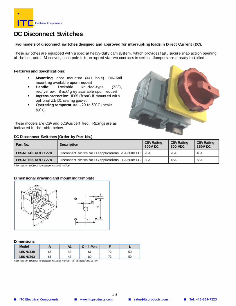
DC Disconnect Switches Two models of disconnect switches designed and approved for interrupting loads in Direct Current (DC). These switches are equipped with a special heavy-duty cam system, which provides fast, secure snap action opening of the contacts. Moreover, each pole is interrupted via two contacts in series. Jumpers are already installed. Features and Specifications:
Mounting: door mounted (4+1 hole). DIN-Rail mounting available upon request
Handle: Lockable knurled-type (Z33), red/yellow. Black/grey available upon request
Ingress protection: IP65 (front) if mounted with optional Z1/D1 sealing gasket
Operating temperature: -20 to 50˚C (peaks 80˚C)
These models are CSA and cCSAus certified. Ratings are as indicated in the table below. DC Disconnect Switches (Order by Part No.)
Part No. Description CSA Rating 600V DC
CSA Rating 500 VDC
CSA Rating 350V DC
LBS-NLT40/4E/DC/Z78 Disconnect switch for DC applications, 20A 600V DC 20A 28A 40A
LBS-NLT63/4E/DC/Z78 Disconnect switch for DC applications, 30A 600V DC 30A 45A 63A Information subject to change without notice Dimensional drawing and mounting template
Dimensions
Model A A1 C – 4 Pole F L LBS-NLT40 66 48 61 72 50
LBS-NLT63 66 48 80 73 59 Information subject to change without notice – All dimensions in mm
1 8

NOTES
o x
1 9
