discipline engineering standard - nsw signalling · discipline engineering standard - nsw category...
TRANSCRIPT

Discipline Engineering Standard - NSW
Category Signalling
Title
Light Signals
Reference Number
SPS 11 - (RIC Standard: SC 07 10 00 00 SP)
Document Control
Status Date Prepared Reviewed Endorsed Approved
Standards and Systems
Standards Engineer
GM Infrastructure
Strategy & Performance
Safety Committee Issue 1
Revision 3 May 05 Refer to
Reference Number
H Olsen M Owens Refer to minutes
of meeting 12/08/04

Engineering Standard – NSW Signalling SPS 11 Light Signals
Issue 1 © Australian Rail Track Corporation Revision 3 This document is uncontrolled when printed May 2005 Page 2 of 91
Disclaimer Australian Rail Track Corporation has used its best endeavors to ensure that the content, layout and text of this document is accurate, complete and suitable for its stated purpose. It makes no warranties, express or implied, that compliance with the contents of this document shall be sufficient to ensure safe systems of work or operation. Australian Rail Track Corporation will not be liable to pay compensation in respect of the content or subsequent use of this document for any other purpose than its stated purpose or for any purpose other than that for which it was prepared except where it can be shown to have acted in bad faith or there has been willful default. Document Approval The technical content of this document has been approved by the relevant ARTC engineering authority and has also been endorsed by the ARTC Safety Committee. Document Supply and Control The Primary Version of this document is the electronic version that is available and accessible on the Australian Rail Track Corporation Internet and Intranet website. It is the document user’s sole responsibility to ensure that copies are checked for currency against the Primary Version prior to its use. Copyright The information in this document is Copyright protected. Apart from the reproduction without alteration of this document for personal use, non-profit purposes or for any fair dealing as permitted under the Copyright Act 1968, no part of this document may be reproduced, altered, stored or transmitted by any person without the prior written consent of ARTC.
Engineering Standard – NSW Signalling SPS 11 Light Signals
Issue 1 © Australian Rail Track Corporation Revision 3 This document is uncontrolled when printed May 2005 Page 3 of 91
About This Standard This specification defines the requirements for colour light signals which may be used on the Australian Rail Track Corporation system in New South Wales.
Requirements for signals illuminated by LEDs are specified as well as the requirements for lampcases, posts, ladders and landings and for termination of wires and cables.
Standard wiring diagrams for both signal lampcases and signal assemblies are provided.
Engineering Standard – NSW Signalling SPS 11 Light Signals
Issue 1 © Australian Rail Track Corporation Revision 3 This document is uncontrolled when printed May 2005 Page 4 of 91
Document History
Primary Source – RIC Standard SC 07 10 00 00 SP Version 3.0
List of Amendments –
ISSUE DATE CLAUSE DESCRIPTION 1.1 01/09/2004 Reformatting to ARTC Standard 1.2 14/03/2005 Disclaimer Minor editorial change 1.3 06/05/2005 All Document reformatted

Engineering Standard – NSW Signalling SPS 11 Light Signals
Issue 1 © Australian Rail Track Corporation Revision 3 This document is uncontrolled when printed May 2005 Page 5 of 91
Contents
1. General.......................................................................................................................8 1.1. Scope ................................................................................................................8 1.2. Incandescent Lamps .........................................................................................8 1.3. Quality Assurance .............................................................................................8 1.4. Warranty............................................................................................................8 1.5. Service Life .......................................................................................................9 1.6. Referenced Documents ....................................................................................9 1.7. Definitions .......................................................................................................10
1.7.1 Signals / Indications ..........................................................................10 1.7.2 Abbreviations used in this Specification ............................................12 1.7.3 Terminology.......................................................................................13 1.7.4 LED Light Source & Signal Case External Aperture Sizes................14
1.8. Environmental Conditions ...............................................................................15 1.8.1 General .............................................................................................15 1.8.2 Wind Loading ....................................................................................15
2. Lampcases ...............................................................................................................16 2.1. Construction ....................................................................................................16 2.2. Multiple Aspect Lampcases ............................................................................17 2.3. Lampcases - Maximum Dimensions ...............................................................17 2.4. Lampcase Brackets.........................................................................................18
2.4.1 Top of Post Brackets .........................................................................18 2.4.2 Front of Post Brackets.......................................................................18 2.4.3 Tunnel Signal Brackets .....................................................................19
3. Hoods and Backgrounds ..........................................................................................20 3.1. Hoods..............................................................................................................20 3.2. Backgrounds ...................................................................................................20
4. Signal Structures ......................................................................................................22 4.1. Ladders ...........................................................................................................22 4.2. Signal Posts ....................................................................................................22
4.2.1 Signal Post Foundations ...................................................................22 4.2.2 Signal Post Landings.........................................................................23 4.2.3 Ladder Gallery Rings.........................................................................24
5. Systems of Safe Access and Safe Working .............................................................25 5.1. Fall Restraint Anchorage Points......................................................................25
5.1.1 Signal Posts ......................................................................................25 5.1.2 Gantries.............................................................................................25
6. Painting ....................................................................................................................26
7. Identification Plates & Notice Plates.........................................................................27

Engineering Standard – NSW Signalling SPS 11 Light Signals
Issue 1 © Australian Rail Track Corporation Revision 3 This document is uncontrolled when printed May 2005 Page 6 of 91
7.1. Identification Plates .........................................................................................27 7.2. Notice Plates ...................................................................................................27
8. Signal Telephones....................................................................................................28
9. Assembly of Signals .................................................................................................29 9.1. General ...........................................................................................................29
9.1.1 Marking .............................................................................................29 9.2. Alignment ........................................................................................................30
10. Forms of Signals and Indicators...............................................................................31 10.1. Signals ............................................................................................................31
10.1.1 Main Lampcase - 200mm diameter...................................................31 10.1.2 Marker Light - 127mm diameter ........................................................31 10.1.3 Subsidiary - 127mm diameter ...........................................................32 10.1.4 Running Turnout Unit - 127mm diameter ..........................................32 10.1.5 Turnout Repeater – white aspect ......................................................32 10.1.6 "A", "CO" and "U" Lights - 200mm diameter .....................................32 10.1.7 Vertical Shunt, Horizontal Shunt & Dwarf Signals - 127mm diameter32 10.1.8 Repeater Signal - Main (90mm diameter Lens) ................................33 10.1.9 Repeat Signal - Low Speed or Shunt - 127mm diameter..................33
10.2. Route Indicators ..............................................................................................33 10.2.1 Miniature Route Indicators ................................................................33 10.2.2 Large Multi-lamp Indicator.................................................................34
10.3. Warning Lights ................................................................................................34 10.4. Guards Indicators - 127mm diameter..............................................................35 10.5. Tunnel Fire Phone Light..................................................................................35
11. Optic Systems ..........................................................................................................36 11.1. LED Optical Systems ......................................................................................36
11.1.1 Common Performance & Design Criteria ..........................................36 11.1.1.1. Optical Requirements .....................................................36
11.1.2 Reliability & Spares ...........................................................................41 11.1.3 Submissions for Type Approval.........................................................41 11.1.4 Signals and Indicators - Details.........................................................43
11.1.4.1. Main Indication................................................................43 11.1.4.2. Tunnel Signals ................................................................43 11.1.4.3. Subsidiary and Shunt Indications 127 / 140mm diameter43 11.1.4.4. Guards Indicators ...........................................................44 11.1.4.5. Turnout Repeaters..........................................................44 11.1.4.6. Signal Repeaters (White light Type) ...............................44 11.1.4.7. Ground Form Indicator (Colour Light Type)....................45 11.1.4.8. ‘A’ Lights & 'U' Lights ......................................................45 11.1.4.9. 'CO' Lights ......................................................................45 11.1.4.10. Route Indicators – small / miniature type........................45 11.1.4.11. Route Indicators - main / large type................................46 11.1.4.12. Tri-colour main signals....................................................46 11.1.4.13. Warning Lights................................................................46 11.1.4.14. Tunnel Fire Safety Phone Light ......................................47 11.1.4.15. Indicator Notice Boards ..................................................47 11.1.4.16. Phantom Reducer...........................................................48

Engineering Standard – NSW Signalling SPS 11 Light Signals
Issue 1 © Australian Rail Track Corporation Revision 3 This document is uncontrolled when printed May 2005 Page 7 of 91
12. Electrical - General ...................................................................................................49 12.1. Transformers...................................................................................................49 12.2. Resistors .........................................................................................................49 12.3. Termination .....................................................................................................49 12.4. Wiring Specifications.......................................................................................50
12.4.1 Wiring within Lampcases...................................................................50 12.4.2 Wiring Between Lampcase(s) and Base ...........................................51
12.5. Electrical Requirements for LED Modules ......................................................51 12.5.1 Alternating Current fed LED Light Design .........................................51
12.5.1.1. Current Proving for SSI Signal Modules .........................52 12.5.2 Direct Current fed LED Light Design.................................................53
12.5.2.1. General ...........................................................................53 12.5.2.2. Computer Based Interlocking Systems...........................53
12.5.3 Non Compliance................................................................................54
13. Wiring Diagrams.......................................................................................................55
14. Drawings ..................................................................................................................67
Appendix A: Capacitive Coupling: Testing Procedure .......................................................91

Engineering Standard – NSW Signalling SPS 11 Light Signals
Issue 1 © Australian Rail Track Corporation Revision 3 This document is uncontrolled when printed May 2005 Page 8 of 91
1. General
1.1. Scope
This specification defines the requirements for the manufacture of LED type railway light signals including but not limited to:
• Main line signals, both single and double aspect types.
• Dwarf signals, both horizontal and vertical types.
• Subsidiary signals.
• Route indicators.
• Turnout indicators.
• Turnout Repeaters.
• Signal Repeaters.
• Marker lights, warning lights, “CO” lights, “A” lights and “U” lights
• Guards indicators and buffer stop lamps.
• Light signals for use in tunnels.
• Tri-colour main signals.
• Tunnel Fire Safety Phone Light.
• Indicator Notice Boards.
1.2. Incandescent Lamps
As incandescent lamps have a relatively short life span and require higher levels of maintenance than LED lights, their use is not encouraged where an LED alternative is available. The section on incandescent signal lights has been removed from this document and is available in the previous version or on request.
1.3. Quality Assurance
Railway signal manufacturers and/or assemblers are expected to hold Quality Assurance Certification to AS/NZS ISO 9000:2000.
1.4. Warranty
All signals and associated parts, supplied to this specification or any Appendix thereto, shall be warranted against defect in manufacture and/or assembly for a period of at least two years from date of manufacture. This warranty shall cover but not be limited to such items as transformers, lamp-holders, relays, terminals, printed circuit boards and connections to components thereon, LEDs, lampcases, backgrounds, hoods, posts, ladders and finishes. Consumable items such as lenses are not included in this requirement, but shall be warranted for compliance with this and any referenced specification and as being ‘fit for purpose’. LED modules may

Engineering Standard – NSW Signalling SPS 11 Light Signals
Issue 1 © Australian Rail Track Corporation Revision 3 This document is uncontrolled when printed May 2005 Page 9 of 91
be considered consumable items and shall be warranted against defects in components or manufacturing and against more than 10 % loss of rated light output for at least five years from date of dispatch from supplier.
1.5. Service Life
Signals and all related components shall be manufactured and assembled to maximise reliability, availability and maintainability and shall be designed, manufactured and assembled to provide a minimum service life of at least 25 years given normal consumable item replacement.
All structural components shall be designed for an operating life of 100 years, except where otherwise stated in a contract.
With LED modules, based on present technology there is an expectation that the product will provide a minimum service life of 100,000 hours of lit time at 50°C without deterioration of LED light output level by more than 10%.
The photometric requirements within this standard apply to new signals. In service the performance will deteriorate therefore, to ensure that the signal continues to perform at a satisfactory level, specified maintenance programs in accordance with manufacturers stated maintenance regimes or industry standard levels must be adhered to.
1.6. Referenced Documents
The following documents are referenced in this specification:
Australian Standard AS9000 series - Quality Assurance
Australian Standard AS 1874 - Aluminium Ingots & Castings.
Australian Standard AS1734 - Aluminium Sheet & Plate.
Australian Standard AS/NZS 4534 - Hot-dip galvanised (zinc) coatings on fabricated ferrous articles.
Australian Standard AS/NZS 4534 - Zinc & zinc/aluminium-alloy coatings on steel wire.
Australian Standard AS/NZS 4791 - Hot-dip galvanised (zinc) coatings on ferrous open sections.
Australian Standard AS/NZS 4792 - Hot-dip galvanised (zinc) coatings on ferrous hollow sections.
Australian Standard AS 1657 - Fixed Platforms & Ladders.
Australian Standard AS1906 Pt 1 - Retro-reflective Materials.
Australian Standard AS1865 - Aluminium Alloy Bar & Strip.
Australian Standard AS1554.1 - Welding - Steel.
Australian Standard AS1665 - Welding - Aluminium.
Australian Standard AS/NZS 5000:1999 - App & Test - Electric Cables.

Engineering Standard – NSW Signalling SPS 11 Light Signals
Issue 1 © Australian Rail Track Corporation Revision 3 This document is uncontrolled when printed May 2005 Page 10 of 91
1.7.1
Australian Standard AS/NZS2144 - Traffic Signal Lanterns.
Australian Standard AS/NZS1891.4:2000 - Industrial Fall Arrest Systems & Devices.
British Standard BS469 - Railway signal Lamps.
AREMA Signal Manual Part 7.1.10 - Colours for Signal Lenses
ARTC Specification SPS 23 - Single Phase Air Cooled, Isolating Transformer for Signalling Applications.
ARTC Specification SPS 45 - Cables for Railway Signalling Applications - Single Conductor Cables for Indoor Use.
ARTC Specification SPS 12 - Signal Lamps.
Signal Drawings M01-114, M01-307 - Signal Posts and bases.
Signal Drawings M01-156, M01-157 - Static Line Installation Guidelines
Signal Drawings M01-300, M01-303, 310 - Signal Post Foundation Details
Signal Drawings M01-159, M01-160 - Signal Post Access Guidelines.
ARTC Specification SPS 02 - Environmental Conditions.
ARTC Specification SPS 05 -Electrical & Electronic Components (Ratings & Construction Requirements).
ARTC Specification SDS 01 - Signal Design Principles, Signals.
ARTC Specification SCP 04 - Lightning and Surge Protection Requirements'.
1.7. Definitions
Signals / Indications
Main Signal:
A main signal displaying one or more red, yellow, green or white indications.
Marker Light:
A signal with a red or in the case of 'distant' signals, a yellow indication mounted on the same post, or in the same cage, as the associated main signal.
Subsidiary Signal:
A signal with indications mounted on the same post, or in the same cage, as the associated main signal displaying green or yellow.
Shunt Signal:
A signal, usually but not necessarily, ground mounted, with two red and one yellow
Engineering Standard – NSW Signalling SPS 11 Light Signals
Issue 1 © Australian Rail Track Corporation Revision 3 This document is uncontrolled when printed May 2005 Page 11 of 91
indications.
Ground Form Indicator Signal:
For the purposes of this specification, a signal using the same lampcase as a vertical shunt signal but with one or more red, yellow and green indications.
Repeater Signal:
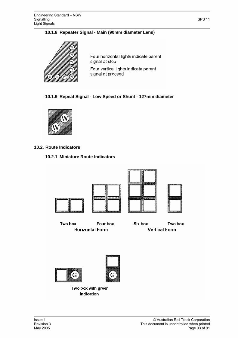
A signal displaying four vertical white lights for a “parent signal at proceed” indication and four horizontal white lights for a “parent signal at stop” indication.
Low Speed or Shunt Repeat:
A signal displaying two inclined white lights.
Turnout Unit:
A signal mounted on the same post as, or in the same cage as, a main signal, containing a marker light and one or two bands of yellow lights consisting of three indications. The bands may be inclined 45° left, 45° right or 45° left and right.
Turnout Repeater:
Also known as a junction repeater. A signal, generally mounted on the same post as, or in the same cage as a main signal, or stand-alone containing one or more bands of white lights. The bands may be inclined 45° left, 45° right or a combination of 45 left and right.
Route Indicator:
An indicator capable of displaying white letters or numerals which relate to a particular track or route. Used in association with a signal to indicate to the driver the route set. May be associated with a main signal or a subsidiary signal.
The following types are presently in common use:
- Miniature
- Large
A'-Lights and 'U'-Lights:
An indicator displaying a white letter 'A' or an indicator displaying a white letter 'U'. An 'A' Light is used to designate 'Automatic'.
A 'U' Light is used to designate 'Unattended'.
CO'-light:
An indicator displaying the white letters 'CO' used as a subsidiary signal for Call-On moves.
Guards Indicator:
An indicator displaying a light blue (outdoor application) or blue (NSR underground

Engineering Standard – NSW Signalling SPS 11 Light Signals
Issue 1 © Australian Rail Track Corporation Revision 3 This document is uncontrolled when printed May 2005 Page 12 of 91
1.7.2
airport line) indication located on a station platform.
Warning Light:
A circular white indication for outdoor use.
In tunnels and outdoors from North Sydney to Redfern, a 300 x 50mm yellow vertical bar is used.
Buffer Stop Light:
A red indication or a white indication over a red indication.
Tri-colour Signal:
A single aspect mainline size housing displaying a red or yellow or green indication.
Tunnel Fire Phone Light:
An indicator displaying a rectangular light blue indication where used in the City underground.
Indicator Notice Boards:
A large board indicator displaying an instruction to the train driver.
Abbreviations used in this Specification
AREMA
'American Railway Engineering and Maintenance of way Association'.
CB
'Common battery'.
cd
'Candela' SI Unit of Luminous Intensity. Equivalent to 1 lumen/steradian.
CIE
'Commission Internationale de l'Eclairage'.
LED
'Light Emitting Diode'.
MOV
'Metal Oxide Varistor'. Used for surge protection.
NSR
'New Southern Railway'.

Engineering Standard – NSW Signalling SPS 11 Light Signals
Issue 1 © Australian Rail Track Corporation Revision 3 This document is uncontrolled when printed May 2005 Page 13 of 91
1.7.3
PPE
'Personal Protection Equipment'. Typically, taking the form of a body harness and lanyard to enable attachment of a person to the structure being accessed.
PVC
'Polyvinyl Chloride' plastic.
ARTC
'Australian Rail Track Corporation'.
Terminology
Approving Authority
An authorised signals engineering representative of the Rail Infrastructure Corporation, New South Wales.
Bright daylight
This implies a clear sky background luminance (lux) in excess of 50,000 cd/m². Chromaticity Coordinates
Two numbers which fix the position of a point on a colour diagram in order to numerically and graphically represent the colour of a light source.
Clear sighting distance
A colour and night vision normal person viewing a signal must be able to easily and correctly read the signal against a day time bright clear sky background and a night time black background, in cab conditions, with 20/20 or corrected eyesight.
The terms 'clear visibility', 'clearly visible' or 'clearly legible' used within this document are defined as a reasonable person being able to unambiguously interpret a signal/indication at the minimum sighting distance under normal expected ambient conditions for the intended application.
Refer to Signal Design Principles document titled 'Signals', with a reference number of SDS 01, for further details.
Dominant wavelength
Dominant wavelength is derived from the CIE Chromaticity Diagram and defines colour in terms of a single wavelength in nanometres (nm). It is that single wavelength of light that has the same perceived colour as the LED radiated spectrum. Dominant wavelength is not necessarily the peak wavelength.
Highway-Rail Crossing Red
The preferred colour of red light suitable for viewing by members of the public at railway / road level crossings. Refer to chromaticity definition in section 11.1.1.1.
LED turn-on Voltage
The voltage applied to the signal at which one or more individual LEDs first begin to

Engineering Standard – NSW Signalling SPS 11 Light Signals
Issue 1 © Australian Rail Track Corporation Revision 3 This document is uncontrolled when printed May 2005 Page 14 of 91
1.7.4
glow.
Lens
The component of the optical system which distributes the luminous flux from the light source into a preferred direction which may also filter the light to give a desired colour. The outer lens also provides a barrier from dust and moisture.
Luminous Intensity
The concentration of luminous flux emitted in a specified direction. Unit: Candela (cd)
Luminance
The luminous intensity of an area of the surface divided by that area. Unit: Candela per square meter (cd/m²).
Phantom signal
An external or internal source of light reflecting from the optical surface of an aspect such that the aspect could be mistaken for an 'illuminated' state. I.E. an 'extinguished' signal appears 'illuminated'.
Shinkolite
A brand name neutral grey tinted acrylic with no red-brown colour content (#560). This definition is not unique and is provided for guidance.
Veiling reflection
The reflection of incident light from an aspect such that the aspect appears white or de-saturated in colour. I.E. an 'ON' signal is obscured or appears white or an indeterminate colour.
LED Light Source & Signal Case External Aperture Sizes
It is desirable that brands of colour light LED modules be interchangeable across a broad range of signal head designs and that signal aperture diameters remain consistent when viewed by train drivers.
Whilst the actual signal face light aperture diameter (allowing for a reasonable tolerance) of an LED signal has little to do with perception from a distance; because the light is perceived as extending wider than the source aperture diameter; the proportions between main, subsidiary and other standard aspect sizes whether incandescent or LED type, shall remain consistent.
A design which in the opinion of the approving authority deviates significantly from the accepted 'nominal' diameter, may be rejected.
The following signal case nominal light aperture diameters shall apply for LED signals:
• Main signal aspects shall be a nominal 'eight inch' design based on the AREMA '8-3/8 inch' size outer lens.

Engineering Standard – NSW Signalling SPS 11 Light Signals
Issue 1 © Australian Rail Track Corporation Revision 3 This document is uncontrolled when printed May 2005 Page 15 of 91
1.8.1 General
1.8.2
• Circular subsidiary aspects shall be a nominal 'five inch' design based on the AREMA '5-3/8 inch' size outer lens.
• For 90mm diameter aspects, typically used in tunnel systems, the actual diameter of the light source aperture, shall be as close as practical to 90mm and in any case, the tolerance shall not exceed +/- 2mm. The light aperture size may be achieved by fitting a 90mm diameter stencil.
• For 45mm diameter aspects used in tunnel systems such as a low speed or shunt, the actual diameter of the aperture, shall be as close as practical to 45mm and in any case, the tolerance not to exceed +/- 2mm. The light aperture size may be achieved by fitting a 45mm diameter stencil.
Where secondary optics are not used to ensure an even dispersement of light across the signal face light aperture; the diameter of an LED array light source behind the aperture shall be as close as practical to the nominal diameter of the aperture.
1.8. Environmental Conditions
Equipment shall conform to the requirements laid down in the ARTC Specification SPS 02 - Environmental Conditions.
All signals and indicators shall be rated for 100% duty and all components therein shall be capable of operating, when continuously illuminated, in ambient temperatures to 50°C in the shade with relative humidity to 95% and exposure to full sunlight.
The operating temperature range of LED signals and associated equipment shall be – 10 to +70°C immediately surrounding the electronic modules.
Proof of compliance to SPS 02 is required in the form of a formal test report carried out by an independently accredited laboratory however, a waiver may be issued on request where it can be shown that the design is based on:
• proven, good engineering design principles or alternatively,
• an existing currently approved and acceptable product which has been in service successfully for an extended period of time.
Wind Loading
Signal posts, gantries, lamp cases, backgrounds, hoods and other associated signalling equipment and structures located outdoors shall be able to withstand without damage, wind loadings of up to 160km/hr:
Where signals equipment is located north of the Coffs Harbour cyclone line at latitude -30, the wind resistance design rating shall be increased to a minimum of 200km/hr.

Engineering Standard – NSW Signalling SPS 11 Light Signals
Issue 1 © Australian Rail Track Corporation Revision 3 This document is uncontrolled when printed May 2005 Page 16 of 91
2. Lampcases
2.1. Construction
Materials used in the lampcase assembly shall be mutually compatible under the operating and environmental conditions experienced in normal service.
The preferred materials for lampcases shall either be a medium strength, high corrosion resistant cast aluminium alloy to AS 1874 or a medium strength, high corrosion resistant aluminium alloy sheet to AS1734. Alternative materials may be used if guarantees of similar service life, robustness and resistance to vandalism, when compared to the aluminium, can be provided. Painting shall be in accordance with section 5. Hinges shall use corrosion free materials such as stainless steel. Where stainless steel threads are in direct contact with aluminium, an appropriate insulation product shall be applied to reduce galvanic action.
Lampcases shall be of sufficient size to accommodate the components required to be fitted therein, and to provide reasonable access to maintain or change components with the minimum disturbance to other components.
LED circuit boards/modules shall be separately removable from the lampcase either from the rear or the front of the lampcase. Designs where non-captive screws are used requiring access from both the front and the back at the same time, will not be accepted.
All lampcases including tunnel signals shall be to the greatest possible extent weatherproof, insect proof and dustproof so as to operate in accordance with the rates of deterioration and maintenance program assumed in the design. Notwithstanding, provision shall be made for ventilation by means of a small breather in the signal case door.
Doors shall be rearward opening and shall be provided with a hasp or similar device which can be secured by the standard padlock (shown on drawing 071000 / 001). Closed doors shall form an effective light proof, weather proof and dust proof seal with the lampcase.
Unused cable entry apertures to be sealed with a screwed plug or bolted plate of similar material to the case.
Screw penetration of the signal case for the mounting of components etc within the case, shall be minimised, except where it can be shown that to do so is unavoidable. Any penetrations are to be compression gasket sealed or where applicable, combined with a neutral cure sealant. Bolt or cable penetrations made against horizontal surfaces shall be fully sealed against water ingress using flexible compression gaskets, 'O' rings, sealant or a combination of the above.
Where cable conduits or cable glands are to terminate onto curved surfaces such as signal masts, a flat section of steel shall be fully welded onto the pipe to provide a flat sealable surface. Where the inside of a pipe or enclosure cannot be easily accessed to fit a conduit terminator/cable-gland nut, the wall of the pipe or enclosure shall be threaded with a minimum of six threads.
Where a number of single aspect lampcases are combined to form a multi-aspect lampcase, the joint between lampcases shall be effectively sealed and the individual doors on the lampcases shall be combined into a single door with single point

Engineering Standard – NSW Signalling SPS 11 Light Signals
Issue 1 © Australian Rail Track Corporation Revision 3 This document is uncontrolled when printed May 2005 Page 17 of 91
securing.
The lampcase and ancillary equipment shall be free from sharp corners and projections which could cause injury to personnel during normal installation and maintenance procedures.
There shall be no possibility of light leakage into any lampcase by way of the access door or any ventilators, or light leakage between lampcases in an assembly or between aspects in any one lampcase.
2.2. Multiple Aspect Lampcases
Multiple aspect lampcases may be made up from any combination of single aspect, two aspect or three aspect lampcases to display up to four aspects.
The bottom lampcase or the bottom section of the lowest lampcase shall contain sufficient terminals of the type specified herein to enable termination of the cable or wiring from the signal base to all aspects within the multiple aspect lampcase or lampcase assembly. The terminals shall be mounted not less than 20mm above the bottom of the lampcase to avoid any moisture which may be present.
Where wiring passes between individual lampcases in the assembly or through partitions in a lampcase, it shall be protected by bushes which shall also form a light seal between lampcases or sections of the lampcase.
2.3. Lampcases - Maximum Dimensions
Signal lampcases shall not exceed the following dimensions:
Lampcase Type Width Height Main Lampcase 300mm N.A. Subsidiary shunt, low-speed, call-on 300mm 300mm Turnout Unit 600mm - Turnout Repeater 600mm - Signal Repeater (white lights) 650mm - Horizontal Shunt Signal 355mm 400mm Vertical Shunt Signal 195mm 550mm Small Route Indicator 355mm 200mm Large Route Indicator 600mm 600mm Warning Light, Guards Indicator, Buffer Stop Lamp
300mm 300mm
Tunnel signal - 2-light case Tunnel signal - 4-light case
195mm 195mm
425mm 800mm
Note 1: These dimensions do not include backgrounds.
Note 2: Slight variances to the above dimensions may be permitted, on application to the approving authority.

Engineering Standard – NSW Signalling SPS 11 Light Signals
Issue 1 © Australian Rail Track Corporation Revision 3 This document is uncontrolled when printed May 2005 Page 18 of 91
2.4.1
2.4.2
2.4. Lampcase Brackets
The brackets securing the lampcase to the signal post shall preferably be manufactured from hot dip galvanised mild steel. Other materials will be considered, provided it can be clearly demonstrated that the material has a service life exceeding 100 years and that it is capable of carrying the abnormal loads which may occur (such as a maintainer using the bracket as a step or support).
Brackets shall be arranged and attached to the signal post so that one person can carry out adjustment for signal aligning (focusing). Where it is necessary to rotate front of post brackets on the post to align the lampcase, a support ring shall be provided to support the bracket during the alignment process.
Where it is necessary to rotate the lampcase for maintenance purposes, such as cleaning or changing lenses, the support ring shall take the form of a locating ring such that the lampcase can be returned to its correct alignment after maintenance. The lampcase bracket and ring shall be provided with a locating pin to clearly define the correct position.
The locating ring shall be provided on all main, turnout and junction indicator lampcases mounted in gantry cages and shall be provided for the lower main lampcases of double aspect post mounted signals
Top of Post Brackets
Where a lampcase is to be mounted onto the top of the post, the bracket shall consist of a socket which fits over the post and is secured to it by U-bolt, clamp or hardened point set or grub screws or other approved means. The bracket shall provide vertical tilt adjustment for the lampcase between 8 degrees downward and 2 degrees upward. Adjustment shall be infinitely variable by screw thread.
Provision shall be made for wiring from the signal post to pass through the top of the socket into the base of the signal lampcase. The wiring entry shall form a rain and insect proof seal in both lampcase and socket but shall permit the wiring or cable to rotate freely within the socket.
Note: Main Line Route Indicators, Turnout Repeaters and other like sized lampcases shall wherever possible, be mounted directly onto the post. It is no longer acceptable to mount a MLRI directly on the top of another lampcase, except in a retro-fit situation where there is no other reasonable option.
Front of Post Brackets
Where a main lampcase or turnout unit is to be mounted in front of the post, the bracket shall accept the same socket used to fix the lampcase to the top of the post. The bracket shall be able to rotate on the post so that the lampcase can be mounted directly in front of the post or offset by up to 200mm to the right (when facing the signal). The bracket shall provide sufficient clearance from the post to permit lampcase doors to be fully opened.
Brackets for subsidiary signals (other than turnout units) shall provide for the lampcase to be mounted directly in front of the post or 200mm to the left or right of the post. The bracket shall provide at least 5 degrees of vertical adjustment and ±10 degrees of horizontal adjustment in addition to being able to rotate around the post.

Engineering Standard – NSW Signalling SPS 11 Light Signals
Issue 1 © Australian Rail Track Corporation Revision 3 This document is uncontrolled when printed May 2005 Page 19 of 91
2.4.3 Tunnel Signal Brackets
Brackets for tunnel signals shall be manufactured from the same (or a compatible) material as the signal lampcases. Case penetrations shall be fully sealed against water ingress.
The bracket shall be placed between the upper and lower lampcases and shall provide for a minimum of ± 5 degrees of lampcase rotation in the horizontal plane. The bracket shall be designed to hold the lampcases 25 - 30mm off the tunnel wall.
Fixing to tunnel walls shall be with suitable stainless steel masonry anchors (not less than 10 mm thread diameter) and if the bracket is manufactured from aluminium, it shall be insulated from the anchors with nylon bushes and washers.
Galvanised steel brackets shall not be used in tunnels.

Engineering Standard – NSW Signalling SPS 11 Light Signals
Issue 1 © Australian Rail Track Corporation Revision 3 This document is uncontrolled when printed May 2005 Page 20 of 91
3. Hoods and Backgrounds
3.1. Hoods
All signal aspects (except tunnel signals) and all indicators shall be fitted with hoods. The hoods may be made from aluminium alloy at least 1.6mm thick.
The minimum length and cover for hoods shall be:
Indication Length mm Cover
Main Line 200mm nominal dia. Refer notes 1 & 2.
375 >225°
Subsidiary 127 or 140 dia. and Repeater (each indication)
200 >225°
Route Indicator - Small. 125mm 300 Top and both sides – also divider between
indications
Route Indicator - Large. 400mm 500 Top and both sides
Turnout Repeater 500 Top and both sides
‘CO’, 'U' and ‘A’ lights. Refer note 5.
375 >225°
Repeater 500 Top and both sides
Guards Indicator. Refer note 3. 200 >225°
Warning Light (outdoor circular) Refer note 3.
200 >225°
Note 1: Minor variations to hood dimensions may be permitted, on application to the approving authority.
Note 2: Where main line signals are placed on a gantry, a one piece hood, covering all indications in the lampcase and 375mm long at the top tapering to 300mm long at the bottom shall be used in place of individual hoods on each indication.
Note 3: Fit hood where necessary.
Note 4: Reducing plates shall not be affixed to hoods.
Note 5: Where there is no reasonable alternative, stencils may be secured to the hood, incorporating at least four points of attachment. The design shall be such that there will be no light spillage from the sides of the stencil arrangement.
3.2. Backgrounds
Where shown in Section 3, Form of Signals, lampcases shall be fitted with a background of the size specified herein. The background may be made from aluminium 5052 H36 or H38 or similar minimum 1.6mm thick.

Engineering Standard – NSW Signalling SPS 11 Light Signals
Issue 1 © Australian Rail Track Corporation Revision 3 This document is uncontrolled when printed May 2005 Page 21 of 91
Lampcase Background Size
Main Line Lampcase – Standard Background Refer note 1.
600mm wide, projecting at least 200mm above the top aspect and 25mm below the bottom aspect
Main Line Lampcase – Narrow Background
450mm wide.
Subsidiary Shunt, Low 450mm diameter Speed, Close-up, Call-on – Standard Background
Subsidiary ShuntLow Speed, Close-up, Call-on – Narrow Background
375mm diameter
Repeater As shown on drawing
Note 1: Where a signal is mounted in a gantry cage, the individual lampcase backgrounds may be replaced by a single full length background fitted to the rear of the cage, provided that this background is effective for all of the approach view of the signal.

Engineering Standard – NSW Signalling SPS 11 Light Signals
Issue 1 © Australian Rail Track Corporation Revision 3 This document is uncontrolled when printed May 2005 Page 22 of 91
4.2.1
4. Signal Structures
The completed equipment shall be hot dip galvanised in accordance with AS 1397, AS/NZS 4791 & AS/NZS 4792 with a galvanised coating weight of 450g/sq metre.
Steel cables to be coated to AS/NZS 4534.
4.1. Ladders
Signal ladders shall comply with AS/NZS 1657 “Fixed Platforms, Walkways, Stairways and Ladders” in respect to minimum size of stile and rung, spacing of rungs and minimum width of ladder. Ladders shall be set at 70 to 75 degrees. Ladders and associated brackets and bolts shall be hot dip galvanised as detailed above.
A concrete landing pad for ladders used on signal posts shall be 600 x 900 x 200mm minimum, with F72 mesh. Where more than one ladder is fitted to a signal post, a single concrete pad shall be formed and poured linking all ladders, wherever possible.
A ladder cage shall be provided where a person could fall from a ladder more than 6.0m however, a 10mm diameter steel fixed static line may take the place of the cage, where specified. Where required to be fitted, static lines shall generally be fitted according to guideline drawings M01-156 and M01-157. Where a static line is fitted, a lockable guard shall be fitted over the first 2.5m of the ladder, to prevent use by unauthorised personnel. The ladder guard shall also be provided with an approved warning notice.
4.2. Signal Posts
Signal posts shall be manufactured from 125 nominal bore heavy (5.4mm wall thickness) steel tube in accordance with drawing M01-144 with an integral base and terminal box equivalent to that detailed on drawing M01-307, unless specified otherwise. The completed post and associated fittings shall be hot dip galvanised as above.
All cable or wiring entry/exit holes in the signal post shall have corners and edges ground or filed to remove any burrs.
Where cable conduits or cable glands are terminated onto the signal post, a flat section of steel shall be fully welded onto the pipe and threaded with a minimum of five threads, to provide a flat sealable surface.
Signal post access designs shall comply where possible with guideline drawings M01-159 and M01-160.
Where design changes or modifications to the structure are required due to local conditions, approval must be sought from an approved design engineer and safety coordinator for risk assessment.
Signal Post Foundations
Foundations may be pre-cast or cast-in-situ type, and unless structural analysis for a non standard design indicates otherwise, shall conform to the following:
Engineering Standard – NSW Signalling SPS 11 Light Signals
Issue 1 © Australian Rail Track Corporation Revision 3 This document is uncontrolled when printed May 2005 Page 23 of 91
4.2.2
• Pre-cast foundations shall be in accordance with the latest version of drawing M01-300 and M01-303.
• Cast-in-situ foundations shall be in accordance with the latest version of drawing M01-310.
Signal Post Landings
Unless specified otherwise, landings shall be provided on, but provision is not limited to, the following situations:
• All double light 5, 6 and 7 aspect signals.
• Double light signals with main line route indicators for access to the route indicator, the upper lampcase and for access to the lower lampcase.
• Single light signals with turnout units for access to the turnout unit.
• Single light signals with subsidiary signals for access to the subsidiary signal, any route indicator and the marker light.
• Single light signals with main line route indicators for access to the route indicator, main line lampcase and for access to marker light and/or other subsidiary signal.
• As otherwise specified in any particular specification or order.
Landing/platform designs which require a person to step out into unsupported free space and around a ladder to gain access, will no longer be permitted.
Safe access shall be provided for the maintenance of any and all lampcases on the signal post. It should not be necessary for maintenance staff to stand anywhere other than on the ladder within the ladder gallery ring (where fitted) or on a landing platform, to maintain any lampcase equipment.
Access to the landing shall be provided by means of a fixed ladder. A safety chain shall be provided at the top of the ladder fitted at handrail height to prevent a person stepping back and falling from a landing.
Where access is required to low or intermediate height signal cases, access may be provided by a landing, a ladder or neither, pending the work height and outcome of a risk analysis.
Where a person needs to work underneath a landing, ladder or other part of a structure, there shall be sufficient space to stand upright and work comfortably and in any case, there should be a minimum of 2 meters between the floor of the lower work area and the underside of any upper structure.
Where space restrictions do not permit a landing to be used, other means of approved safe access shall be provided.
All landings and handrails shall be designed for the live loadings specified in AS/NZS 1657 for fixed platforms and handrails.
Landings shall be at least 600mm wide between handrails and a minimum of 750mm long.

Engineering Standard – NSW Signalling SPS 11 Light Signals
Issue 1 © Australian Rail Track Corporation Revision 3 This document is uncontrolled when printed May 2005 Page 24 of 91
4.2.3
Ladder stiles shall extend up to the handrail. The handrail shall extend along both sides and across the front of the landing. A toe rail projecting at least 100mm above the landing shall be provided along both sides and across the front of the landing, generally in accordance with AS/NZS 1657.
Signal post landings shall be provided with guardrails / handrails of height 1.1 m unless specified otherwise and conforming to AS/NZS 1657.
Steel landings, handrails and associated brackets and bolts shall be hot dip galvanised as detailed above.
Landings and ancillary equipment shall be free from sharp corners and projections which could cause injury to personnel during normal installation and maintenance procedures.
Where there is a clearance issue with a risk of a person striking their head on the structure above, this should be identified with high visibility hazard tape. Hazard tape should be self adhesive black on white. Tape is not to be placed on rungs nor on any other surface which may be trodden on.
Ladder Gallery Rings
Where landings are not provided at the top of the ladder, ladder gallery rings shall be fitted unless the gallery ring would be at a height of less than two metres. The gallery rings shall be made from minimum 50 x 6 mild steel hot dip galvanised as detailed above and shall be at 90 degrees to the signal post and of 600 mm diameter unless otherwise specified. The gallery rings shall be braced from the ladder on both sides to prevent movement.
Gallery rings are not to be used for attaching PPE.

Engineering Standard – NSW Signalling SPS 11 Light Signals
Issue 1 © Australian Rail Track Corporation Revision 3 This document is uncontrolled when printed May 2005 Page 25 of 91
5.1.1
5.1.2 Gantries
5. Systems of Safe Access and Safe Working
Working at heights can present a fall hazard to personnel. The primary means of fall control when accessing and working on signal posts and gantry structures will be by means of cages and handrails conforming to AS/NZS 1657.
Where these primary means of fall control cannot be fitted due to structure gauge or other space restrictions, PPE in the form of limited fall arrest system/s may be specified in lieu. In some cases, limited fall arrest PPE systems may be specified in addition to primary fall protection equipment for reasons such as rescue and recovery or where the risk of injury is considered high enough to warrant their use.
In general, the design of safety systems shall comply to the latest requirements of the appropriate Australian Standards, the Occupational Health and Safety Legislation and ARTC Safety Standards.
5.1. Fall Restraint Anchorage Points
Where rescue and or fall protection systems requiring a person to wear a body harness and lanyard are specified at a signal post or gantry structure, suitably rated anchorage points will be required to be incorporated into that structure. Anchor points, their locations and the structure to which they are attached shall conform to the requirements of AS/NZS 1891.4 : 2000, and must be designed by an approved engineer. Safe means of access to an anchorage point in accordance with AS/NZS 1657 must be provided.
Anchorages for the connection of two persons shall be designed for a minimum force loading of 21 kN.
Anchorages for the connection of one person shall be designed for a minimum force loading of 15kN.
Signal Posts
Anchorage points and associated fixing structure shall generally conform to the 21 kN force loading. In the case of retrofit applications to existing signal posts, the structure may be rated for 15kN however, the attachment point itself shall be rated for 21 kN.
Anchorages and associated fixing structure shall conform to the 21 kN force loading as a minimum.
Where specified, signal cages may require the fitting of a suitable anchorage point such as an eye-bolt or davit above the cage. Anchorage points are typically required to be positioned above the signal cage at a suitable height to assist in the rescue/recovery of persons and to enable the connection of a PPE lanyard.

Engineering Standard – NSW Signalling SPS 11 Light Signals
Issue 1 © Australian Rail Track Corporation Revision 3 This document is uncontrolled when printed May 2005 Page 26 of 91
6. Painting
The paint finishes and colours for lampcases and other signal components shall be:
Component Location Finish
Lampcases Interior Matt or semi-gloss black
Lampcases Exterior Matt or semi-gloss black
Fixtures etc Inside lampcases
Matt or semi-gloss black
Bezels Matt or semi-gloss black
Backgrounds Front Matt black
Backgrounds Rear Semi-gloss white
Hoods Matt black
Posts, ladders,
Brackets etc.
No painting - galvanised finish to AS/NZS 4680, AS/NZS 4791 & AS/NZS 4792 if steel. Anodised or natural finish if aluminium.
Note 1: Powder coating, enamels or vinyl co-polymer finishes may be used. The finishes, primers and undercoats are to be applied strictly in accordance with the recommendations published by the finish coat manufacturer.
Note 2:The interior surface of hoods and the front of backgrounds shall be finished matt black so as to minimise reflections of the illuminated signal; semi-gloss or gloss finish is not acceptable.
Note 3: The rear of the background shall be painted white as specified above. It is permissible that the whole of the rear of the signal case be painted white.

Engineering Standard – NSW Signalling SPS 11 Light Signals
Issue 1 © Australian Rail Track Corporation Revision 3 This document is uncontrolled when printed May 2005 Page 27 of 91
7. Identification Plates & Notice Plates
7.1. Identification Plates
The identification plates to be fitted to each signal shall consist of AS 1906 Part 1 Class 1 retro-reflective numerals and letters on a black non-reflective background fixed to a 2 mm thick Aluminium Alloy plate or extrusion.
The layout of letters and numerals and size of plate shall be in accordance with ARTC drawing 071000 / 002. Refer to section 14 of this document.
Plates shall be attached to signals in the positions shown on ARTC drawings 071000 / 005 to 071000 / 025. Refer to section 14 of this document.
7.2. Notice Plates
Where required, driver’s notice or instruction plates shall be fitted to the signal post below the lowest aspect but above any signal telephone.
If there is insufficient space on the signal post to fit the notice plate, it shall be mounted on a separate 50NB galvanised steel post adjacent to the signal and in full view of the driver of any train standing at the signal.
Notice plates shall be fixed to posts with two (2) galvanised U-bolts or stainless steel clamp bands.

Engineering Standard – NSW Signalling SPS 11 Light Signals
Issue 1 © Australian Rail Track Corporation Revision 3 This document is uncontrolled when printed May 2005 Page 28 of 91
8. Signal Telephones
Signal telephones shall be fitted to the posts of all Automatic signals except Distant signals unless otherwise specified in the particular specification.
The phone shall be a magneto or CB type in a vandal resistant case, preferably without separate handcom, and securely attached to the signal post to prevent unauthorised removal or damage.
The phone shall be mounted so that it is 1450 - 1600 mm above ground (or any platform) level at the base of the signal.
Engineering Standard – NSW Signalling SPS 11 Light Signals
Issue 1 © Australian Rail Track Corporation Revision 3 This document is uncontrolled when printed May 2005 Page 29 of 91
9.1.1 Marking
9. Assembly of Signals
9.1. General
Signals shall be assembled in the forms shown on drawings 071000 / 005 to 071000 / 025.
All bolts, U-bolts, nuts, washers etc used in assembly shall be galvanised, zinc plated or cadmium chromate plated steel or stainless steel. Brass bolts, screws etc shall not be used in contact with any aluminium component and aluminium bolts may only be used in non load bearing applications.
Assembly of both lampcase components and complete signals shall provide for ease of maintenance, i.e. lamp changing, lens replacement, relay replacement, adjustment of signal focus.
Anti-seize compound shall be applied to metal-threads which are external to the lampcase and which are likely to be disturbed during maintenance activities during the expected service life of the signal. Thread sealant shall be applied to metal-threads where they penetrate a signal casing. The product must allow the metal-threads to be removed for maintenance activities without damage.
All wiring within lampcases and between lampcases and signal base shall be double insulated from metal. All openings for wiring in posts and lampcases shall have rounded edges. In addition any cable or wiring entry opening through metal less than 2 mm thick shall be fitted with an insulating bush. Wiring shall be in accordance with the circuit diagrams shown herein.
Each multiple aspect lampcase or lampcase assembly and each turnout unit shall have a circuit diagram of the internal wiring of the lampcase on photo anodised aluminium or equivalent fixed permanently to the inside of the door. The required wiring diagrams are shown in section 13 of this document.
Each signal post shall have a circuit diagram of the wiring between base and lampcases on photo anodised aluminium or equivalent permanently fixed to the inside of the base door.
Each lampcase shall have a circuit diagram of the wiring between the incoming terminal strip and the equipment contained therein on photo anodised aluminium or equivalent permanently fixed to the inside of the lampcase door. The label within the lampcase shall include but is not limited to the following details:
• Manufacturer / Supplier,
• Model / Catalogue number,
• Brief description of product,
• Rated nominal operating voltage,
• Batch code/Serial number,
• Simple wiring diagram,
Engineering Standard – NSW Signalling SPS 11 Light Signals
Issue 1 © Australian Rail Track Corporation Revision 3 This document is uncontrolled when printed May 2005 Page 30 of 91
• Date of manufacture and or expiry date.
The wiring diagrams for double head and single head signal bases are shown in section 13 of this document. These complete diagrams are to be used irrespective of the indications in use.
LED PCBs/modules shall be clearly and permanently marked as to colour when de-energised with any additional markings necessary for the correct selection of replacement parts.
Note: It is recommended that items be marked in accordance with AS/NZS ISO9000 to facilitate product identification and traceability as required for the application of the quality management system based on the provisions of the standard.
9.2. Alignment
Where a number of single unit lampcases are used to make up a two, three or four aspect lampcase, assembly shall be such that the light beams from each unit lampcase are parallel to one another in both the horizontal and vertical planes.
Engineering Standard – NSW Signalling SPS 11 Light Signals
Issue 1 © Australian Rail Track Corporation Revision 3 This document is uncontrolled when printed May 2005 Page 31 of 91
10.1.1
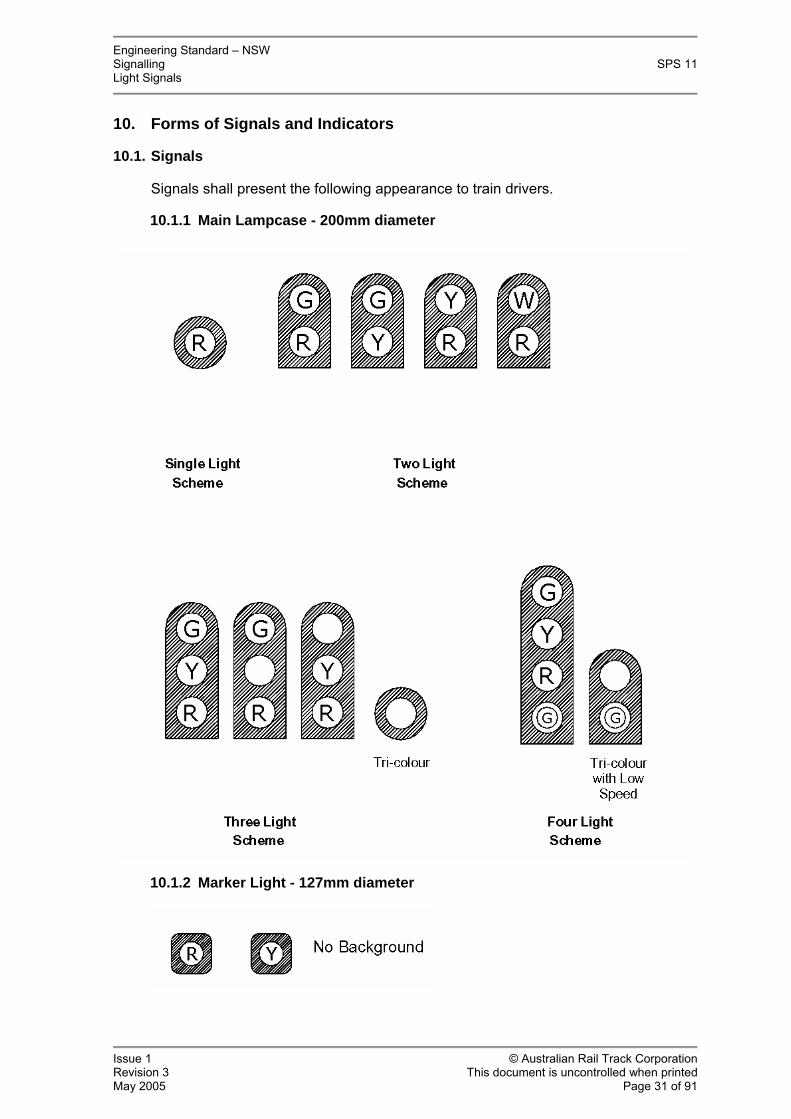
10. Forms of Signals and Indicators
10.1. Signals
Signals shall present the following appearance to train drivers.
Main Lampcase - 200mm diameter
10.1.2 Marker Light - 127mm diameter
Engineering Standard – NSW Signalling SPS 11 Light Signals
Issue 1 © Australian Rail Track Corporation Revision 3 This document is uncontrolled when printed May 2005 Page 32 of 91
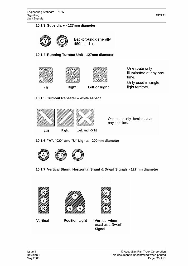
10.1.3 Subsidiary - 127mm diameter
10.1.4 Running Turnout Unit - 127mm diameter
10.1.5 Turnout Repeater – white aspect
10.1.6 "A", "CO" and "U" Lights - 200mm diameter
10.1.7 Vertical Shunt, Horizontal Shunt & Dwarf Signals - 127mm diameter
Engineering Standard – NSW Signalling SPS 11 Light Signals
Issue 1 © Australian Rail Track Corporation Revision 3 This document is uncontrolled when printed May 2005 Page 33 of 91
10.1.8 Repeater Signal - Main (90mm diameter Lens)
10.1.9 Repeat Signal - Low Speed or Shunt - 127mm diameter
10.2. Route Indicators
10.2.1 Miniature Route Indicators

Engineering Standard – NSW Signalling SPS 11 Light Signals
Issue 1 © Australian Rail Track Corporation Revision 3 This document is uncontrolled when printed May 2005 Page 34 of 91
10.2.2 Large Multi-lamp Indicator
10.3. Warning Lights

Engineering Standard – NSW Signalling SPS 11 Light Signals
Issue 1 © Australian Rail Track Corporation Revision 3 This document is uncontrolled when printed May 2005 Page 35 of 91
10.4. Guards Indicators - 127mm diameter
10.5. Tunnel Fire Phone Light

Engineering Standard – NSW Signalling SPS 11 Light Signals
Issue 1 © Australian Rail Track Corporation Revision 3 This document is uncontrolled when printed May 2005 Page 36 of 91
11.1.1
11. Optic Systems
11.1. LED Optical Systems
LED indications are the preferred optical system for all colour-light signals.
This section describes the requirements in terms of general appearance, form, viewability distance, colour and operating voltage.
Common Performance & Design Criteria
11.1.1.1. Optical Requirements
The colours of LED signals and indications shall be as specified in section 1.6 of this specification and as defined in the Chromaticity Table.
To determine compliance with this standard; colours and luminous intensity shall be tested according to acceptable recognised standards such as those specified in AS/NZS 2144:2002 and by laboratories which are independently accredited as having competence to carry out the type of measurements involved. The colour of the light emitted from each signal aspect defined in terms of its chromaticity coordinates, shall fall within the area of the CIE 1931 chromaticity diagram boundary envelope as defined within this document.
Colour shall be achieved by careful selection of LED. Mixing of different coloured LEDs to achieve the specified result is not acceptable except where approved or specified by the approving authority; an example being where current LED technology cannot provide the desired colour. Coloured filters shall not be used except where required by the approving authority.
An even and equal disbursement of light intensity across the entire face of the signal aperture is required, and is to be achieved by a minimum number of evenly dispersed LEDs as specified for each light, on the following pages of this document. The centre to centre distance between any two adjacent LEDs should not be greater than twice the LED lens diameter unless approved otherwise. The use of a diffuser or secondary optics which provide a uniform display will be considered.
All LEDs used shall be in water clear packages.
The outer surface of the diffuser or cover shall be smooth, manufactured from poly-carbonate and should incorporate features to reduce reflection, phantoms and veiling.
Stencil type and route indicators shall be designed and constructed to minimise distortion, i.e. a sharp clear image without fuzzy edges is required to maximise legibility. The light source shall be covered by a smooth polycarbonate or high impact resistance acrylic cover such that the form of the digit is not readily visible when the indicator is not illuminated. Tinted material such as Shinkolite may be used to reduce the chance of phantoms, providing that the specified minimum readability distance is not compromised. The non illuminated area of the indicator/stencil shall be black or dark grey, to maximise contrast and minimise reflection. White backgrounds shall not be used. Light intensity shall be suitable for both daylight and night time viewing at the rated distance.

Engineering Standard – NSW Signalling SPS 11 Light Signals
Issue 1 © Australian Rail Track Corporation Revision 3 This document is uncontrolled when printed May 2005 Page 37 of 91
The outer face of the printed circuit board shall be matt black in tone.
When standing in front of an outdoor signal, the luminous intensity of that signal is not to be so high so as to cause the driver excessive glare therefore, to limit glare luminous intensity shall not exceed 750 candela from any single aspect, unless approved otherwise. Tunnel lights intensities shall be sufficient to provide clear visibility, without dazzling or otherwise interfering with the vision of train drivers in a tunnel.
Signal sighting distances specified in this document are based on the requirements of ARTC Specification SDS 01 - 'Signal Design Principles, Signals', and are minimum nominal clear sighting distances. In practice, consideration must be given to the proposed location and purpose for which a signal / indicator is intended, to determine the optimum luminous intensity level of the LED signal. Signal luminous intensities are to provide an easily seen signal at the nominated viewing distance with background sky luminance of at least 50,000 cd/m² as well as at night.
LED aspects shall be suitable for flashing with no visible flicker or noticeable start-up delay at turn-on.
Chromaticity Table definitions for LED Lights. Colour Chromaticity
Boundary Definitions LED Dominant Wavelength (8d)
Red y ≤ 0.288 632 - 660 nm (Wayside signals) Refer to notes 1 & 2 below.
y ≥ 0.998-x
Red y ≤ 0.320 615 - 630 nm y ≥ 0.292 (Highway-Rail Crossings)
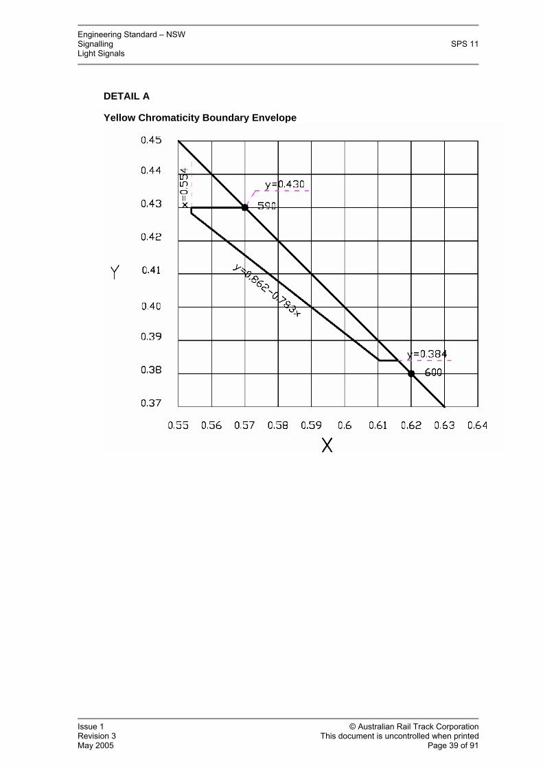
Refer to notes 2 & 3 below. y ≥ 0.998-x Yellow y ≤ 0.430 590 – 595 nm
y ≥ 0.384 y ≥ 0.862 - 0.783x x ≥ 0.554 Green y ≥ 0.506 – 0.519x 500 – 510 nm
y ≥ 0.150 + 1.068x y ≤ 0.817-x White x ≥ 0.285 Not Applicable
x ≤ 0.440 y = 0.050 + 0.750x y = 0.150 + 0.640x
Blue x ≤ 0.179 460 – 481 nm y ≤ 0.209 y ≤ 0.734x + 0.088
Light Blue x ≥ 0.17 Not Applicable (Guards Indicator) x ≤ 0.22
y ≥ 0.14 y ≤ 0.18
Engineering Standard – NSW Signalling SPS 11 Light Signals
Issue 1 © Australian Rail Track Corporation Revision 3 This document is uncontrolled when printed May 2005 Page 38 of 91
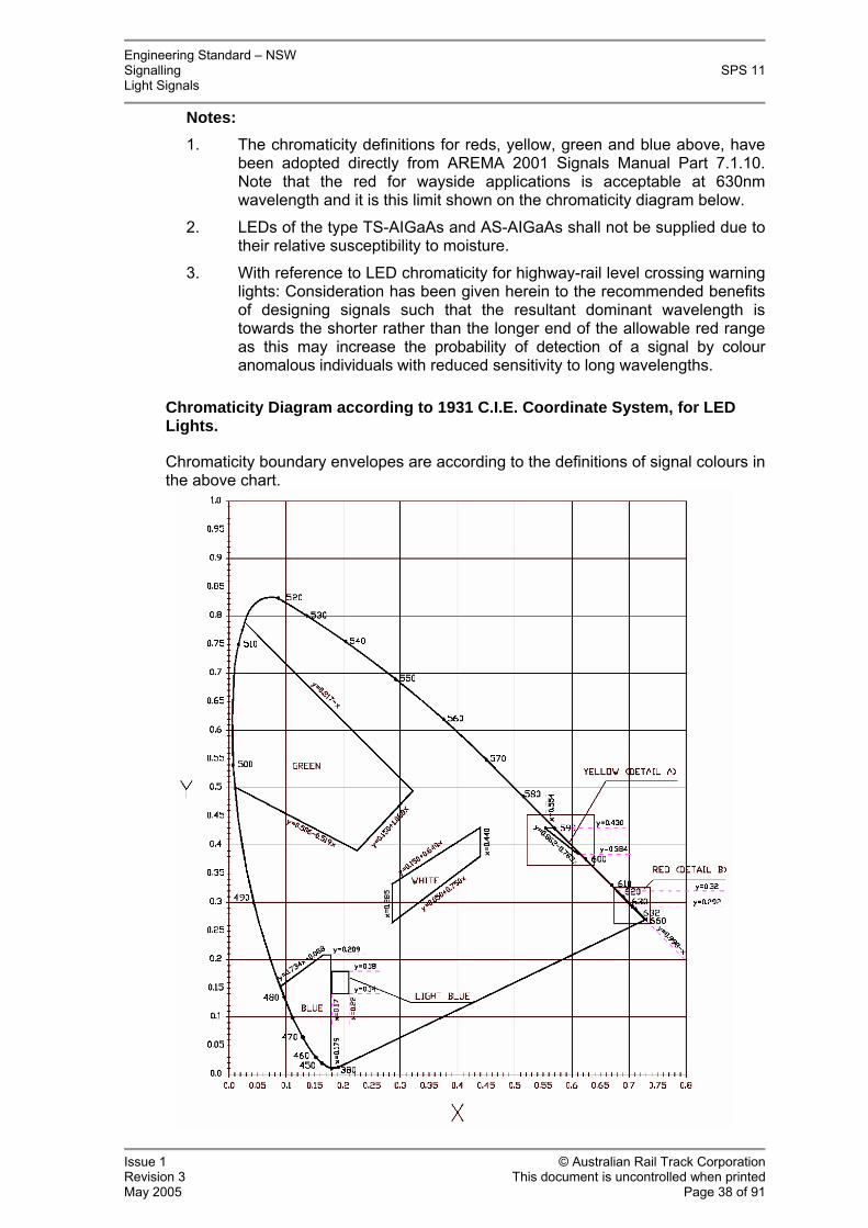
Notes: 1. The chromaticity definitions for reds, yellow, green and blue above, have
been adopted directly from AREMA 2001 Signals Manual Part 7.1.10. Note that the red for wayside applications is acceptable at 630nm wavelength and it is this limit shown on the chromaticity diagram below.
2. LEDs of the type TS-AIGaAs and AS-AIGaAs shall not be supplied due to their relative susceptibility to moisture.
3. With reference to LED chromaticity for highway-rail level crossing warning lights: Consideration has been given herein to the recommended benefits of designing signals such that the resultant dominant wavelength is towards the shorter rather than the longer end of the allowable red range as this may increase the probability of detection of a signal by colour anomalous individuals with reduced sensitivity to long wavelengths.
Chromaticity Diagram according to 1931 C.I.E. Coordinate System, for LED Lights.
Chromaticity boundary envelopes are according to the definitions of signal colours in the above chart.
Engineering Standard – NSW Signalling SPS 11 Light Signals
Issue 1 © Australian Rail Track Corporation Revision 3 This document is uncontrolled when printed May 2005 Page 39 of 91
DETAIL A
Yellow Chromaticity Boundary Envelope

Engineering Standard – NSW Signalling SPS 11 Light Signals
Issue 1 © Australian Rail Track Corporation Revision 3 This document is uncontrolled when printed May 2005 Page 40 of 91
DETAIL B
Red Chromaticity Boundary Envelope

Engineering Standard – NSW Signalling SPS 11 Light Signals
Issue 1 © Australian Rail Track Corporation Revision 3 This document is uncontrolled when printed May 2005 Page 41 of 91
11.1.2
11.1.3
Reliability & Spares
Where all of the LEDs in any one aspect, or any one indication, are powered from a single source on the printed circuit board, the components used in that source shall have a level of reliability equivalent to the LEDs where practical.
LED module test certificates are to be retained / stored by the manufacturer / supplier for a period of not less than seven years. Copies of certificates are to be made available when requested.
All user replaceable parts are to be available from the manufacturer / supplier for the life of the product and are to carry distinct, indelible identification details to ensure that correct replacement parts can be ordered.
Submissions for Type Approval
Submissions must be accompanied by the following minimum base data:
• Manufacturer/supplier details of overall LED module assembly.
• Part/model number and revision if applicable.
• General description (including LED array diameter/dimensions) and application for product.
• Photograph/s or sketch of product where appropriate.
• Price structure.
• Photometric Report providing details of light output intensity (in Candela) vs voltage (in 10V steps for AC and 2V steps for DC) vs current including temperature effects over the specified supply voltage and temperature range and which shall be provided in tabular and graphical form. Note that the LED turn-on voltage point must be identified. Ambient test temperature to be recorded and reported.
• LED chromaticity coordinates to CIE 1931 as well as effective overall measured dominant wavelength (where applicable) as measured when mounted within the applicable lampcase. Ambient test temperature to be recorded and reported.
• Rated operating voltage limits and LED turn on voltage.
• Nominal rated viewing range for observers in cab conditions, in all ambient light conditions.
• Surge protection conformance details.
• Dielectric insulation details.
• Environmental conformance details.
• Number of LEDs, type of LEDs and information on the design details of the electrical arrays/groupings and percentage of light lost on various LED failure modes.

Engineering Standard – NSW Signalling SPS 11 Light Signals
Issue 1 © Australian Rail Track Corporation Revision 3 This document is uncontrolled when printed May 2005 Page 42 of 91
• Light output level at various viewing angles of aspect at nominal supply voltage.
• Cabling distance rating for AC LED lights. Refer to section 12.5 & Appendix A.
• Warranty details including replacement turn-around time.
• Product overall MTBF details.
• Overall service life expectancy of a complete signal head (excluding consumable items).
• Where available from the LED manufacturer, a projected degradation and illumination on-time in hours figure, or alternatively, a calculated estimation.
• Materials used for body, front lens and other relevant parts.
• Quality assurance standard under which the product was manufactured.
• Maintenance and mounting detail instruction sheet if applicable.
• Purchase order delivery turnaround times.
• Manufactures recommended method/s for lamp proving.
• Suppliers point by point statements of compliance or otherwise, to this ARTC Standard.
Once a product is type approved for use on the New South Wales Railways, specifications are not to change without prior written approval from the approving authority otherwise approval may be withdrawn.
Once approved for use on New South Wales Railways, if in the opinion of the approving authority the product has been changed significantly, the authority may request a representative new production sample (one off) of the approved LED colour light product to be tested and a compliance report provided by the vendor, highlighting any changes from the original specification.
The report shall include as a minimum:
• Photometric details of light output intensity (in Candela) vs voltage (in 10V steps for AC and 2V steps for DC) vs current over the specified supply voltage range and which shall be provided in tabular and graphical form. Note that the LED turn-on voltage point must be identified.
• LED chromaticity coordinates to CIE 1931 as well as effective overall dominant wavelength (where applicable) as measured when mounted within the applicable lampcase.
• Electrical compliance details.

Engineering Standard – NSW Signalling SPS 11 Light Signals
Issue 1 © Australian Rail Track Corporation Revision 3 This document is uncontrolled when printed May 2005 Page 43 of 91
11.1.4 Signals and Indicators - Details
11.1.4.1. Main Indication
The standard optic system for a main light shall be a circular array of not less than 110 LEDs forming a nominal 200mm diameter indication. Pending approval from the approving authority, the number of LEDs may be reduced where secondary optics or alternative technology is used to provide an even disbursement of light across the face of the aperture.
The LEDs shall be current limited and arranged such that a failure of any LED will result in no more than 25% loss of indication.
The LEDs used in main aspects shall be such that, in combination with the diffuser or cover, all signal indications shall be clearly readable in all light conditions at the following sighting distances:
• Standard signal: 500 metres minimum.
• Long Range Signal: 1000 metres minimum. This implies a luminous distribution rate in excess of 6500 cd/m².
In addition, the standard signal shall provide not less than 33% of maximum intensity at an offset angle of ±10° and not less than 10% of maximum intensity at an offset angle of ±20°.
11.1.4.2. Tunnel Signals
The 127 mm nominal diameter light in tunnel signals shall consist of not less than 75 LEDs evenly arrayed within a circle. A reduced number of LEDs and a slightly reduced array diameter may be permitted pending approval by the approving authority. The “low speed” or "shunt" aspect shall have an equivalent density of LEDs. This may be achieved by mounting a stencil with a 45mm diameter aperture in front of a 127mm diameter aspect.
The LEDs shall be current limited and arranged such that a failure of any LED will result in no more than 25% loss of indication.
The diffuser or cover shall be of a type and be located at a distance in front of the LED array which will ensure that:
• Tunnel signals shall be clearly readable at a clear sighting distance of 300 metres; in the ambient light level found in the typical underground tunnel. Lights mounted at tunnel portals may necessitate the fitting of hoods and or increased intensity levels.
• Clear visibility of indication at a viewing angle of 35° either side of the zero axis in the ambient light level found in the typical underground station is required.
11.1.4.3. Subsidiary and Shunt Indications 127 / 140mm diameter
The standard optic system for this light shall be a circular array of not less than 75 LEDs forming a nominal 127mm diameter indication. A reduced number of LEDs and a slightly reduced array diameter may be permitted pending approval by the approving authority.

Engineering Standard – NSW Signalling SPS 11 Light Signals
Issue 1 © Australian Rail Track Corporation Revision 3 This document is uncontrolled when printed May 2005 Page 44 of 91
The LEDs used in Subsidiary and Shunt Indications shall be such that, in combination with the diffuser or cover, shall be clearly readable for a minimum clear sighting distance of 150 meters in all light conditions.
11.1.4.4. Guards Indicators
The 127mm diameter indication shall consist of not less than 80 LEDs evenly arrayed within a circle. LEDs shall be 20° or 30° angle type. Fifteen degree angle LEDs may be used together with a suitable optical diffuser, on approval by the approving authority.
Where LEDs are not available in the specified 'light blue' colour, the desired 'light blue' colour may be achieved by a mix of white and blue LEDs evenly arranged in a nominal mix so as to achieve an even homogeneous dispersal of colour.
This homogeneous disbursement of light may be achieved by the use of an approved diffuser lens.
All guards Indicators shall be fitted with an approved sign advising 'Guards Indicator'. All indicators which are outdoors with any possibility of sunlight on them must be correctly hooded so that the indicator can be clearly seen from below and from a wide viewing angle.
Guards Indicators must be sighted and agreed to as part of the signal sighting surveys and agreed signoffs. Signoff by a guards representative is required to ensure that the indicator is in the best position.
Intensity to range between 40 and 50cd. The guards indication shall be clearly readable at a clear sighting distance of 150 meters at all times in all light conditions. Lamp proving is not required for single indicators.
Note that the lunar white / white guards indicator has been superseded by the 'light blue' indicator.
11.1.4.5. Turnout Repeaters
Turnout repeaters shall have a rectangular band of 195 by 15° or 20° white LEDs arranged in 5 rows of 39 and the LEDs arranged such that open circuit failure of any LED will result in no more than 25% loss of indication and short circuit failure of any LED will result in the loss of only that LED. The LEDs shall be covered by a clear antiglare polycarbonate cover. Diffusion is not required.
Turnouts when illuminated, shall be clearly readable and identifiable for a minimum clear sighting distance of 400 meters in all light conditions.
11.1.4.6. Signal Repeaters (White light Type)
Where individual lights are used they shall be 90mm diameter, each shall contain a minimum of 39 by 15° or 20° white LEDs with the LEDs arranged such that open circuit failure of any LED will result in no more than 25% loss of indication and short circuit failure of any LED will result in the loss of only that LED.
A common printed circuit board may be used for the four “proceed” aspects and similarly for the four “stop”. In this case, the four aspects may be achieved by fitting a stencil with four by 90mm diameter cut-outs in front of an array of white LEDs.

Engineering Standard – NSW Signalling SPS 11 Light Signals
Issue 1 © Australian Rail Track Corporation Revision 3 This document is uncontrolled when printed May 2005 Page 45 of 91
Aspects when illuminated, shall be clearly readable and identifiable for a minimum clear sighting distance of 200 meters in all light conditions.
11.1.4.7. Ground Form Indicator (Colour Light Type)
As for subsidiary and shunt indications detailed in this specification.
11.1.4.8. ‘A’ Lights & 'U' Lights
The letter ‘A’ and the letter 'U' shall be 150mm in height.
When fitted to tunnel signals the letter ‘A’ shall be 100mm in height. The letter shall be formed with LEDs.
Alternatively, a broad array of LEDs combined with an appropriate stencil cut-out, is permitted.
Letter font style to be submitted for approval.
The letter, when illuminated, shall be clearly legible for a minimum clear sighting distance of 50 meters in bright daylight conditions and 100 meters in tunnel conditions.
Note that the blue LED 'A' light for tunnel applications has been superseded by the white LED 'A' light.
11.1.4.9. 'CO' Lights
The letters shall be 140mm in height and shall be formed with white LEDs.
Alternatively, a broad array of white LEDs combined with an appropriate stencil cutout, is permitted. To reduce misinterpretation of indications and maximise contrast, the signal shall present a uniform black or dark grey face to the observer when the ‘CO’ is not lit. This black or dark grey presentation may be achieved by the use of a smoky grey Shinkolite or other approved dark lens material placed in front of the LEDs. Refer to clause 11.1.5 for details of approved Shinkolite product.
Letter font style to be submitted for approval.
The Call On indicator when illuminated, shall be clearly legible for a minimum clear sighting distance of 20 meters in all light conditions.
11.1.4.10. Route Indicators – small / miniature type
Miniature route indicators shall consist of multiple LED light sources which are capable of displaying one or two digits.
Where a bay of the route indicator is required to exhibit only a fixed display, an array of LEDs combined with an appropriate stencil cut-out, is permitted.
Miniature multi-lamp route indicators will be considered and shall consist of 7x7 or 9x9 LED light source arrays.
The minimum height of digits shall be 125mm but may be reduced slightly pending approval by the approving authority and providing that the minimum sighting distance is maintained. Where a double digit display is required, the

Engineering Standard – NSW Signalling SPS 11 Light Signals
Issue 1 © Australian Rail Track Corporation Revision 3 This document is uncontrolled when printed May 2005 Page 46 of 91
digits shall be spaced appropriately so that they do not blend together at the specified viewing distance. Digit font style to be submitted for approval.
LEDs shall be 15° or 20° white.
The digits shall be clearly legible for a minimum clear sighting distance of 50 meters. Digits shall be legible both during bright daylight conditions as well as night conditions without the need for dimming.
11.1.4.11. Route Indicators - main / large type
Large route indicators shall consist of multiple LED light sources which are capable of displaying a number of different alphanumeric characters, one at a time. Digits may be formed using individual LEDs or clusters of LEDs.
Displays may be of the matrix type using 7x7 or 9x9 pixel arrays, or a string of individual LED lights may be used to form the shape of each character.
The display digits shall not be readily visible when not illuminated.
The minimum character size shall be 400mm in height and preferably larger.
The large medium range route indicator when illuminated, shall be legible for a minimum reading distance of 200 meters. Digits shall be legible both during bright daylight conditions as well as night conditions. For high speed lines, longer sighting distances may be required.
11.1.4.12. Tri-colour main signals
Tri-colour signals comprise three different colour lights in a nominal 200mm diameter single head housing.
The standard system and colours for a main tri-colour signal shall be as defined in section 1.6 of this specification, the 'Chromaticity Table' further above and as defined for 'main indications'.
Active and neutral connections shall be electrically isolated from each colour aspect in the same signal light module and from all other aspects in the same signal head. Each aspect within a signal light module shall have fully independent and electrically isolated power supplies. Refer to ARTC Specification SPS 05 - Electrical & Electronic Components (Ratings & Construction Requirements) for minimum requirements.
Terminal strips within lampcases shall have provision for busing together the neutral connections using proprietary bus bars. However, the bus bar/s with screws etc shall not be fitted but rather, supplied loose within a plastic bag firmly attached to the light assembly.
Best visibility minimum clear sighting distances are as per 'main indications'.
11.1.4.13. Warning Lights
Warning lights when illuminated, shall be visible for a minimum clear sighting distance of 150 meters in all light conditions. Where used in tunnels, the intensity may need to be reduced to minimise glare.

Engineering Standard – NSW Signalling SPS 11 Light Signals
Issue 1 © Australian Rail Track Corporation Revision 3 This document is uncontrolled when printed May 2005 Page 47 of 91
White round warning lights are normally used in all applications.
Round warning lights shall be a nominal 127mm diameter and have a minimum number of 36 white LEDs.
The use of rectangular yellow warning lights is limited to and bounded by the Eastern Suburbs line (Erskinville Portal to Bondi Junction) and the City Underground area limited by the country end of Redfern Station and the City end of Waverton Station.
Rectangular warning lights shall be 50mm wide by 300mm high and consist of a minimum matrix of 120 LEDs arranged in a reasonable number of columns. The LEDs shall be arranged in four separate series current limited strings with each string randomly distributed among the columns. LED colour shall be yellow. There are three types of these rectangular lights comprising:
• One LED matrix, mounted perpendicular to the tunnel wall.
• Two LED matrices, one facing in either direction, angled slightly away from the tunnel wall.
• Three LED matrices, one facing in either direction angled slightly away from the tunnel wall and with one facing directly away from the wall.
The angle of the LED matrix shall be 60 degrees from the wall.
The illumination produced by the light shall be visible from any angle within a tunnel. Further details available on request.
11.1.4.14. Tunnel Fire Safety Phone Light
An indicator displaying a nominal 127mm diameter blue indication.
Tunnel Fire Safety Phone Light, shall be rectangular and have a 75x50mm array of LEDs.
The rectangular light shall comprise of two LED matrices, one facing in either direction, angled slightly away from the tunnel wall. The illumination produced by the light shall be visible from any angle within a tunnel. Light unit to incorporate internal 12 Volt sealed lead-acid gel battery and integral 240 Vac charger. Sealing shall be to IP64 or better. The unit shall incorporate a flash facility to flash the light with a rate of 45 to 90 flashes per minute with a 50% duty cycle, when the handset of the associated telephone is not on the hook. The telephone interface shall comply with all applicable telephone system standards.
The clear sighting distance shall be 300 metres in the ambient light level found in the typical underground station.
Detailed construction specification available on request.
11.1.4.15. Indicator Notice Boards
The large notice board shall not exceed 600mm x 600mm in size. The letters shall be 140mm minimum height and shall be formed with LEDs.
LEDs shall be 15° or 20° white and shall be covered by a diffused cover so that

Engineering Standard – NSW Signalling SPS 11 Light Signals
Issue 1 © Australian Rail Track Corporation Revision 3 This document is uncontrolled when printed May 2005 Page 48 of 91
the array is not readily visible when the lamp is not illuminated.
The large notice board when illuminated, shall be clearly legible for a minimum clear sighting distance of 100 meters in all light conditions.
Other options will be considered
11.1.4.16. Phantom Reducer
“Shinkolite 560” is a high quality neutral grey tinted Polymethyl Methacrylate Acrylic with no red-brown colour content and a light transmittance of 31 % in 3mm thick sheet.
Supplier and product information is available on request. The product is stock coded with three disk sizes.
Since every disk will not necessarily carry a product label, random sample colour testing of each batch of product received shall be carried out. The minimum acceptable test shall sample 10% or 5%, whichever is greater of each batch received. The results of the tests shall be documented and form part of the quality inspection documentation forwarded with lampcases or lens units when these are delivered.

Engineering Standard – NSW Signalling SPS 11 Light Signals
Issue 1 © Australian Rail Track Corporation Revision 3 This document is uncontrolled when printed May 2005 Page 49 of 91
12. Electrical - General
12.1. Transformers
Signal Lighting transformers where fitted shall be rated for continuous operation in an environment with temperatures to 70 degrees C and relative humidity to 95%.
Transformers shall be rated at a minimum of:-30VA for a single LED aspect. 85VA for special LED displays.
The above rating requirements are based on mains frequency transformers typically for use with incandescent lights, and do not apply to PCB mounted or high frequency transformers. Magnetising current to be no more than 60mA RMS.
Construction of the transformers shall be generally in accordance with the requirements of Standard Specification SP 091001 00 SP but shape and size are optional.
12.2. Resistors
Resistors shall operate at 50% or less of their maximum power dissipation at 70°C.
Resistors shall be packaged and mounted to tolerate vibration at the levels laid down in the ARTC Standard Specification SPS 02.
Where resistors are required to be mounted within the lampcase, the supplier shall supply the lampcases with the resistors mounted and wired to a suitable terminal strip.
Where a heat sink is required to attain the manufacturers heat dissipation level, it is permissible to affix the resistor to the body of the lampcase. Heat transfer paste should be provided to ensure good thermal contact.
Where the resistors are to be soldered to wires, wires shall be twisted together and high temperature solder shall be used. The exposed solder joint shall be covered with a sleeve of suitable heat-shrink product.
12.3. Termination
Lampcases and signal bases shall be provided with an approved terminal block.
Either the tunnel screw clamp type or spring cage type approved terminals may be used within the lampcase. The tunnel screw clamp type terminal block shall be designed to allow for the use of crimped pin or blade lugs and shall incorporate a tongue to ensure that the clamping screw does not bear-down directly onto the crimp. Spring cage / cage clamp type terminals shall be of the style which will to allow for the use of crimped pin lugs, though the use of pin lugs in these type of terminals is not necessary.
The terminal shall be able to accept wire sizes of between 0.5 and 2.5mm square, as a minimum.
Wiring to tunnel screw clamp type terminals shall be terminated with approved pre-insulated insulation grip (double grip) crimp pin lugs of the type specified below. Where two wires are fitted into one tunnel terminal, blade lugs shall be used.

Engineering Standard – NSW Signalling SPS 11 Light Signals
Issue 1 © Australian Rail Track Corporation Revision 3 This document is uncontrolled when printed May 2005 Page 50 of 91
12.4.1
In-line connections or crimps shall not be used.
When terminating into tunnel screw clamp type terminals pre-insulated insulation grip pin lugs shall be used:- UTILUX H2286, Cable Accessories PC1.25DG, Panduit PMV1-P10-C/X, Solterco.FVDWSPC-1-1.25.
Crimping tool Utilux 11 C or equivalent shall be used. Crimping tools shall be tested at least once each day and test results shall form part of the quality documentation forwarded with lampcases or signals on delivery.
Insulation displacement types of terminals in either lampcase or base shall not be used under any circumstances.
Terminals shall provide access for testing with a multimeter and or megger meter.
Insulation resistance, terminal to terminal, or terminal to earth or mounting rail shall be greater than 100 meg Ohm when tested at 500 Volts.
The terminals within a lampcase shall allow for the fitting of MOVs or other devices approved by the approving authority, for surge protection, whether the devices are required at the terminals or not.
Surge protection shall be provided for LED signals, either on the LED module or preferably on an approved terminal block within the same enclosure, and shall conform to the ARTC Standard SCP 04 'Lightning and Surge Protection Requirements'.
Where surge protection is not integral to an LED light module, i.e. not provided on the LED circuit board, protection shall be provided by the vendor and fitted on the abovementioned terminals.
Provision shall be made for fixed labelling of each terminal.
Terminals shall be marked according to the terminal numbers shown on the standard circuits herein. Terminals for DC circuits shall be marked with the polarity in addition to the terminal numbers.
12.4. Wiring Specifications
Wiring within Lampcases
Wiring used within lampcases, i.e. between terminals and transformer or transformer and LED board, or terminals and resistor may be single insulated and shall be at least 7 strand copper, not less than 0.87 sq mm in area and shall be insulated in accordance with the requirements of AS/NZS 5000, "Electric cables - Polymeric insulated - For working voltages up to and including 0.6/1 kV”. The insulation shall be at least V - 75 quality.
Where this wiring passes either through or within 5 mm of metal surfaces it shall be protected with a PVC or similar sleeve at least 0.5 mm thick or with an insulating bush.
Wiring layout shall be neat and allow for easy clear access. There shall be no joints or intermediate connections between LED module and signal head terminal strip or between resistors and signal head terminal strip.

Engineering Standard – NSW Signalling SPS 11 Light Signals
Issue 1 © Australian Rail Track Corporation Revision 3 This document is uncontrolled when printed May 2005 Page 51 of 91
12.4.2
12.5.1
Wiring Between Lampcase(s) and Base
Wiring between lampcases and base, if single conductors, shall comply with the requirements of Specification SC11111000SP for 7/0.4 mm cable.
If multi-core cables are used, the cable shall consist of cores which meet the requirements of the above clause, encased in a PVC sheath not less than 1.2 mm thick.
12.5. Electrical Requirements for LED Modules
Wherever applicable, the components used shall comply with the latest requirements of ARTC Specification SC00260000SP (Ratings & Construction Requirements).
Each aspect of a LED signal shall be electrically isolated from all other aspects as well as the lampcase ground, with a minimum degree of isolation of 100 Meg Ohms when measured at 500V. Purpose designed link bars shall be fitted on the incoming terminal strips within the lampcase where neutral wires are to be connected together.
Either the type of LED used and/or the forward current in the LEDs may be varied as required to achieve this result. However, the drive current for each LED shall not exceed the value recommended by the LED manufacturer for achieving the device expected minimum service life of at least 100,000 hours at 50°C.
MOVs of minimum 50 Joule rating shall be supplied fitted to the terminal strip within the lampcase irrespective of whether surge protection is provided within an LED module. Where the LED module is provided for retrofit application, the MOV shall be packed with the lamp.
Current draw of main indications within the same head shall be matched to within 10%.
Alternating Current fed LED Light Design
• LED aspects shall operate from an ac supply voltage range of 100 to 130 Volts 50hz (120 Volts 50Hz nominal supply) and shall operate within this range without significant variation in luminous intensity.
• All 200mm mainline aspects shall draw not less than 100mA and not more than 300mA at 120Vac RMS. Resistors external to the LED module for the purpose of compliance with the above clause will not be permitted.
• LED lights shall be designed to minimise the effects of coupled voltages causing unwanted aspects to be illuminated. Protection against coupled voltages in long supply cables shall be provided such that no LED will illuminate at a supply voltage of less than 40 Volts AC (higher turn-on voltages are preferred).
• AC LED lights shall be suitable for operation with tail cables of up to 750 metres in length as a minimum, without being illuminated due to capacitive coupling in cables. The maximum capacitive coupling in a 750m length of cable can be simulated using a 235nF mains rated capacitor.
Refer to Appendix A for details of testing for capacitive coupling.

Engineering Standard – NSW Signalling SPS 11 Light Signals
If necessary, an approved design four terminal bleed resistor arrangement may be fitted within the signal head to allow a particular LED light to be fed longer distances. These resistor arrangements are to be designed to minimise failure modes which remove a resistor from circuit and leave the LED functioning. The design shall consist of a number of resistors in parallel, so that an open circuit on one resistor does not unduly affect the overall performance of the device. This arrangement shall not be used to match load current of like aspects.
Acceptable concept arrangement showing multiple resistors Connected across signal head terminals.
Note that these distance limitation values are for relay interlocking applications only, as SSI TFMs will shut down with residual voltages on lights, when they are off.
12.5.1.1. Current Proving for SSI Signal Modules
Current proving for SSI Signal Modules requires:
• The current wave shape to be symmetrical around zero.
• There should be only two transitions though 0.6 Volts positive or negative when measured across a resistor in series with the LED module with the resistor sized to drop 0.8 Volts RMS. If more transitions occur they must not be less than 1 mS apart.
• The time for each half cycle exceeding 0.6 Volts positive or negative when measured across a resistor in series with the LED module with the resistor sized to drop 0.8 volts RMS should be greater than 6mS.
Issue 1 © Australian Rail Track Corporation Revision 3 This document is uncontrolled when printed May 2005 Page 52 of 91

Engineering Standard – NSW Signalling SPS 11 Light Signals
Issue 1 © Australian Rail Track Corporation Revision 3 This document is uncontrolled when printed May 2005 Page 53 of 91
12.5.2 Direct Current fed LED Light Design
12.5.2.1. General
LED modules shall operate from a supply Voltage range of 9 to 16 Volts DC and shall operate within this range without significant variation in luminous intensity. Voltage range for level crossing lights shall be at least 8 to 18 Volts DC.
Protection shall be provided such that no LED will illuminate at a supply voltage of less than 4 Volts DC and 5 Volts AC RMS.
12.5.2.2. Computer Based Interlocking Systems
• The current drawn shall be a steady DC current after 100mS with no transients measurable with an Oscilloscope set for a timebase of 1 uS per division.
• Switched power supplies in particular, need to be designed with suitable front end filtering to ensure that the current drawn is steady DC.
• The LED module shall be suitable such that while in the non-energised state, when pulsed ON with a 60us electrical pulse, no light output shall be visible to the naked eye in a darkened environment. Observers to be colour and night vision normal with 20/20 or corrected eyesight.
Conversely, the LED module shall be suitable such that while in the energised state, when turned OFF for 60us, the OFF pulse will not be visible to the naked eye in a darkened environment. Observers to be colour and night vision normal with 20/20 or corrected eyesight.
• LED modules directly driven by CBI lamp output shall draw a current within the range of 1.3 Amperes to 2.8 Amperes with a preference for

Engineering Standard – NSW Signalling SPS 11 Light Signals
Issue 1 © Australian Rail Track Corporation Revision 3 This document is uncontrolled when printed May 2005 Page 54 of 91
minimal current within this range.
Whilst not the preferred solution; current range adjustment may be achieved by fitting suitably rated load resistors within the signal light head of the type specified in section 12.2 of this specification. Where an external resistor solution is required, and where practical, the resistor is to be permanently connected at the LED module such that it is not easily removable independently of the LED module.
Where the resistor cannot be directly connected across the LED module, the arrangement shown below may be permissible. Designs which do not require a resistor external to the LED module for current range compliance, will be the preferred solution.
12.5.3 Non Compliance
Products not in compliance with the last paragraph of section 12.5 and the second paragraph of section 12.5.1 will be accepted until 30th June 2004.

Engineering Standard – NSW Signalling SPS 11 Light Signals
Issue 1 © Australian Rail Track Corporation Revision 3 This document is uncontrolled when printed May 2005 Page 55 of 91
13. Wiring Diagrams
Wiring diagrams for internal lampcase wiring and base to lampcase wiring are shown in this section.
The wiring diagrams for the signal base allocate a unique terminal number for all aspects and indications which can be displayed on the signal.
When assembling a particular signal, only those numbered terminals which are required by the aspects in use on that signal need be fitted to the base. The fitted terminals are to be numbered according to the numbering scheme shown on the following pages.
Eg: For a single head signal with marker light and shunt as shown on drawing 071000 / 007 herein; the following terminals would be installed in the signal base, and numbered as such:
• 1 to 8,
• 29 & 30.
Signal Base Terminal Allocation 5 and 6 light, 120Vac or 12Vdc LED Signals. Refer to standard circuit for detail. Terminal Number Circuit
1 Green positive 2 Green negative 3 Yellow positive 4 Yellow negative 5 Red positive 6 Red negative
7 Lower Green positive 8 Lower Green negative 9 Lower Yellow positive
10 Lower Yellow negative 11 Lower Red positive 12 Lower Red negative
13 Low Speed positive 14 Low Speed negative
15 “A” Light positive 16 “A” Light negative
17 Subsidiary shunt positive 18 Subsidiary shunt negative
19 Route Indicator No. 1 box positive 20 Route Indicator No. 1 box negative 21 Route Indicator No. 2 box positive 22 Route Indicator No. 2 box negative

Engineering Standard – NSW Signalling SPS 11 Light Signals
Issue 1 © Australian Rail Track Corporation Revision 3 This document is uncontrolled when printed May 2005 Page 56 of 91
23 Route Indicator No. 3 box positive 24 Route Indicator No. 3 box negative 25 Route Indicator No. 4 box positive 26 Route Indicator No. 4 box negative
27 Main Line Route Indicator No. 1 route positive 28 Main Line Route Indicator No. 1 route negative 29 Main Line Route Indicator No. 2 route positive 30 Main Line Route Indicator No. 2 route negative 31 Main Line Route Indicator No. 3 route positive 32 Main Line Route Indicator No. 3 route negative 33 Turnout or Signal Repeater left or vertical positive 34 Turnout or Signal Repeater left or vertical negative 35 Turnout or Signal Repeater right or horizontal pos. 36 Turnout or Signal Repeater right or horizontal neg. 37 38
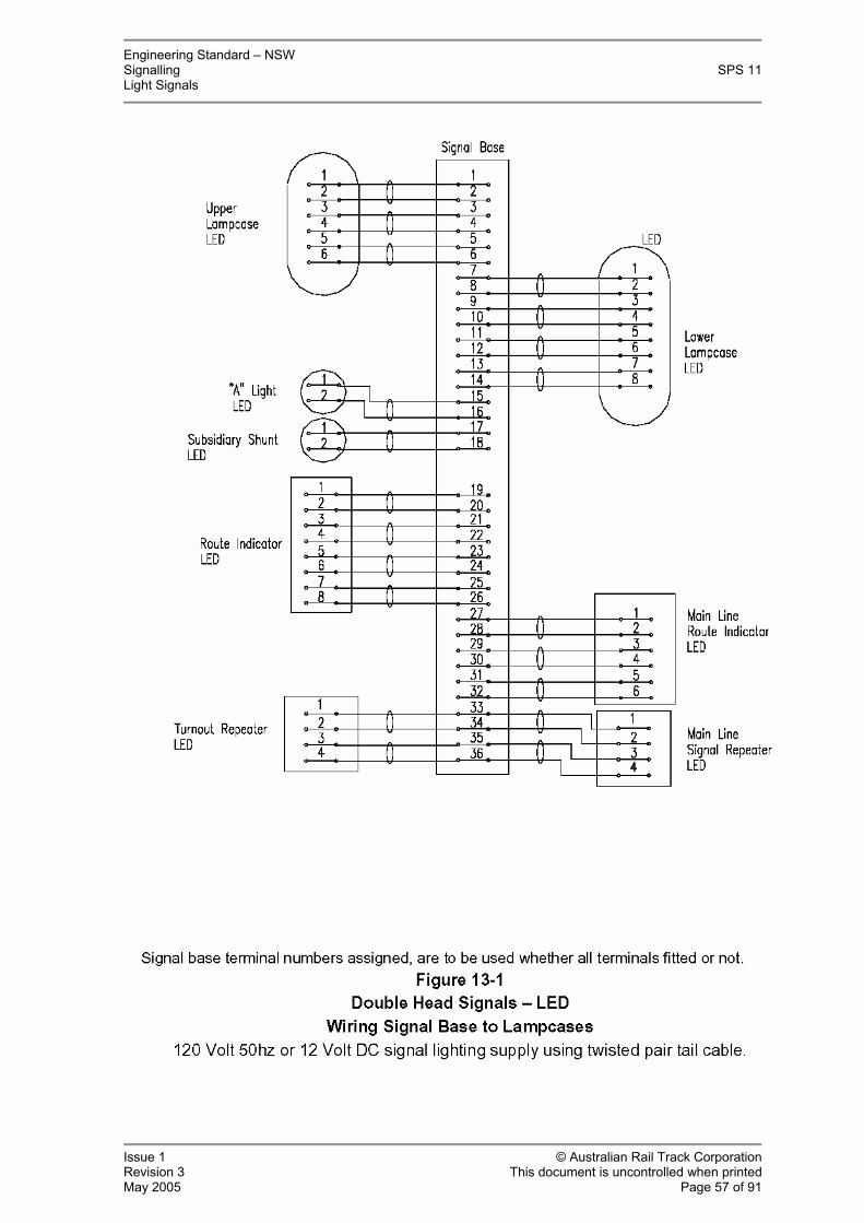
Engineering Standard – NSW Signalling SPS 11 Light Signals
Issue 1 © Australian Rail Track Corporation Revision 3 This document is uncontrolled when printed May 2005 Page 57 of 91

Engineering Standard – NSW Signalling SPS 11 Light Signals
Issue 1 © Australian Rail Track Corporation Revision 3 This document is uncontrolled when printed May 2005 Page 58 of 91
Signal Base Terminal Allocation Single Head, 120Vac or 12Vdc LED Signals. Refer to standard circuit for detail.
Terminal Number Circuit 1 Green positive 2 Green negative 3 Yellow positive 4 Yellow negative 5 Red positive 6 Red negative
7 Marker Light positive 8 Marker Light negative
9 Turnout Unit top LH lamp positive 10 Turnout Unit top LH lamp negative 11 Turnout Unit middle lamp positive 12 Turnout Unit middle lamp negative 13 Turnout Unit bottom RH lamp positive 14 Turnout Unit bottom RH lamp negative 15 Turnout Unit top RH lamp positive 16 Turnout Unit top RH lamp negative 17 Turnout Unit bottom LH lamp positive 18 Turnout Unit bottom LH lamp negative
19 Low Speed positive 20 Low Speed negative
21 Route Indicator No. 1 box positive 22 Route Indicator No. 1 box negative 23 Route Indicator No. 2 box positive 24 Route Indicator No. 2 box negative 25 Route Indicator No. 3 box positive 26 Route Indicator No. 3 box negative 27 Route Indicator No. 4 box positive 28 Route Indicator No. 4 box negative
29 Subsidiary shunt positive 30 Subsidiary shunt negative
31 “A” Light positive 32 “A” Light negative
33 MLRI / Turnout Repeater terminals as required 34 35 36 37

Engineering Standard – NSW Signalling SPS 11 Light Signals
Issue 1 © Australian Rail Track Corporation Revision 3 This document is uncontrolled when printed May 2005 Page 59 of 91

Engineering Standard – NSW Signalling SPS 11 Light Signals
Issue 1 © Australian Rail Track Corporation Revision 3 This document is uncontrolled when printed May 2005 Page 60 of 91

Engineering Standard – NSW Signalling SPS 11 Light Signals
Issue 1 © Australian Rail Track Corporation Revision 3 This document is uncontrolled when printed May 2005 Page 61 of 91

Engineering Standard – NSW Signalling SPS 11 Light Signals
Issue 1 © Australian Rail Track Corporation Revision 3 This document is uncontrolled when printed May 2005 Page 62 of 91
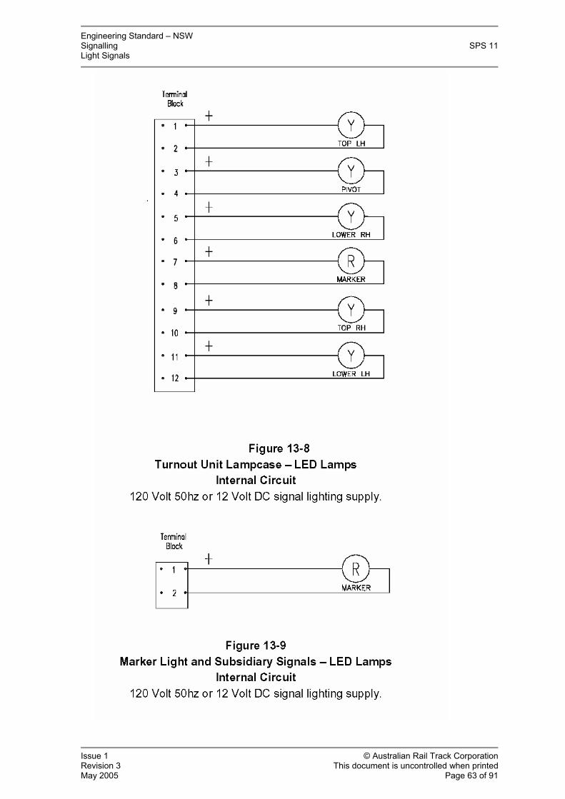
Engineering Standard – NSW Signalling SPS 11 Light Signals
Issue 1 © Australian Rail Track Corporation Revision 3 This document is uncontrolled when printed May 2005 Page 63 of 91

Engineering Standard – NSW Signalling SPS 11 Light Signals
Issue 1 © Australian Rail Track Corporation Revision 3 This document is uncontrolled when printed May 2005 Page 64 of 91

Engineering Standard – NSW Signalling SPS 11 Light Signals
Issue 1 © Australian Rail Track Corporation Revision 3 This document is uncontrolled when printed May 2005 Page 65 of 91

Engineering Standard – NSW Signalling SPS 11 Light Signals
Issue 1 © Australian Rail Track Corporation Revision 3 This document is uncontrolled when printed May 2005 Page 66 of 91

Engineering Standard – NSW Signalling SPS 11 Light Signals
Issue 1 © Australian Rail Track Corporation Revision 3 This document is uncontrolled when printed May 2005 Page 67 of 91
14. Drawings
Contents:
• 071000 / 001 Standard Padlock
• 071000 / 002 Signal Identification Plates
• 071000 / 005 Controlled Signal Single Aspect
• 071000 / 006 Automatic Signal Single Aspect
• 071000 / 007 Controlled Signal Single Aspect with Subsidiary
• 071000 / 008 Controlled Signal Single Aspect with Subsidiary
• 071000 / 009 Controlled Signal Single Aspect with Subsidiary Indication
• 071000 / 010 Single Head Controlled Signal with Turnout
• 071000 / 011 Single Head Signal with “A” Light
• 071000 / 012 Single Head Signal with Turnout and Subsidiary
• 071000 / 013 Single Head Signal with Route Indicator and Turnout
• 071000 / 014 Single Head Signal with Subsidiary and “A” Light
• 071000 / 015 Double Head Signal
• 071000 / 016 Double Head Signal
• 071000 / 017 Double Head Signal
• 071000 / 018 Double Head Signal
• 071000 / 019 Double Head Signal
• 071000 / 020 Double Head Signal
• 071000 / 021 Double Head Signal
• 071000 / 022 Double Head Signal
• 071000 / 023 Single Head Signal with Low Speed Repeater
• 071000 / 024 Controlled Mainline Indicator, Single Head with Turnout
• 071000 / 025 Controlled Mainline Indicator, Single Head

Engineering Standard – NSW Signalling SPS 11 Light Signals
Issue 1 © Australian Rail Track Corporation Revision 3 This document is uncontrolled when printed May 2005 Page 68 of 91

Engineering Standard – NSW Signalling SPS 11 Light Signals
Issue 1 © Australian Rail Track Corporation Revision 3 This document is uncontrolled when printed May 2005 Page 69 of 91

Engineering Standard – NSW Signalling SPS 11 Light Signals
Issue 1 © Australian Rail Track Corporation Revision 3 This document is uncontrolled when printed May 2005 Page 70 of 91

Engineering Standard – NSW Signalling SPS 11 Light Signals
Issue 1 © Australian Rail Track Corporation Revision 3 This document is uncontrolled when printed May 2005 Page 71 of 91

Engineering Standard – NSW Signalling SPS 11 Light Signals
Issue 1 © Australian Rail Track Corporation Revision 3 This document is uncontrolled when printed May 2005 Page 72 of 91

Engineering Standard – NSW Signalling SPS 11 Light Signals
Issue 1 © Australian Rail Track Corporation Revision 3 This document is uncontrolled when printed May 2005 Page 73 of 91
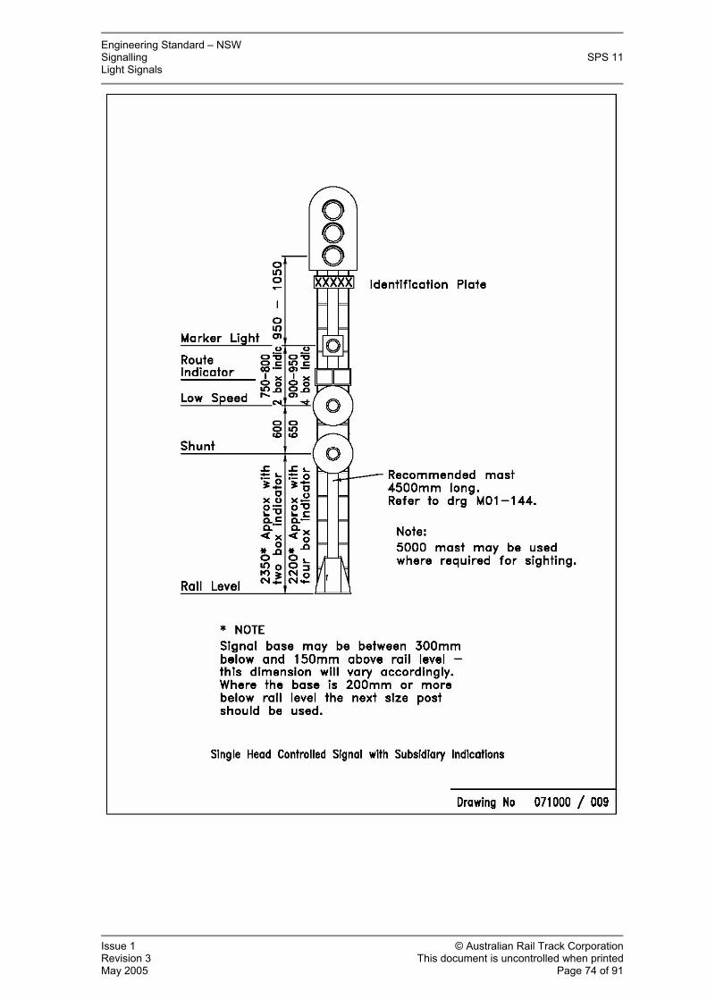
Engineering Standard – NSW Signalling SPS 11 Light Signals
Issue 1 © Australian Rail Track Corporation Revision 3 This document is uncontrolled when printed May 2005 Page 74 of 91

Engineering Standard – NSW Signalling SPS 11 Light Signals
Issue 1 © Australian Rail Track Corporation Revision 3 This document is uncontrolled when printed May 2005 Page 75 of 91
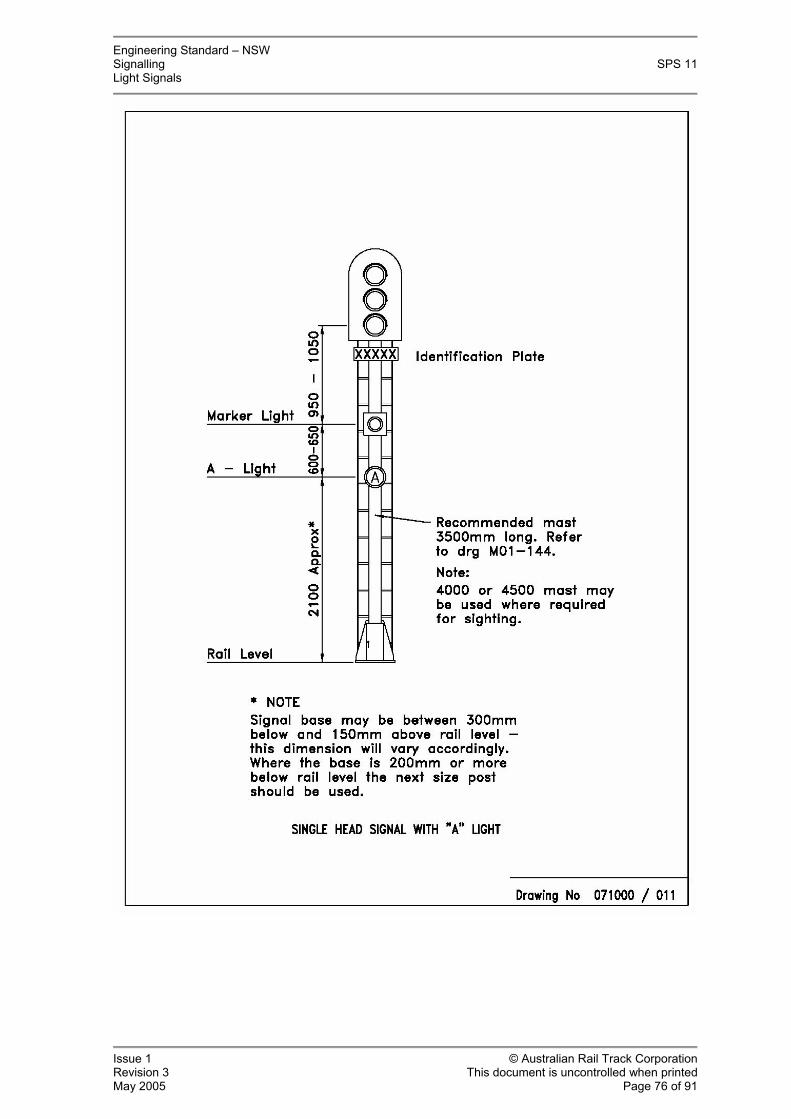
Engineering Standard – NSW Signalling SPS 11 Light Signals
Issue 1 © Australian Rail Track Corporation Revision 3 This document is uncontrolled when printed May 2005 Page 76 of 91

Engineering Standard – NSW Signalling SPS 11 Light Signals
Issue 1 © Australian Rail Track Corporation Revision 3 This document is uncontrolled when printed May 2005 Page 77 of 91

Engineering Standard – NSW Signalling SPS 11 Light Signals
Issue 1 © Australian Rail Track Corporation Revision 3 This document is uncontrolled when printed May 2005 Page 78 of 91

Engineering Standard – NSW Signalling SPS 11 Light Signals
Issue 1 © Australian Rail Track Corporation Revision 3 This document is uncontrolled when printed May 2005 Page 79 of 91
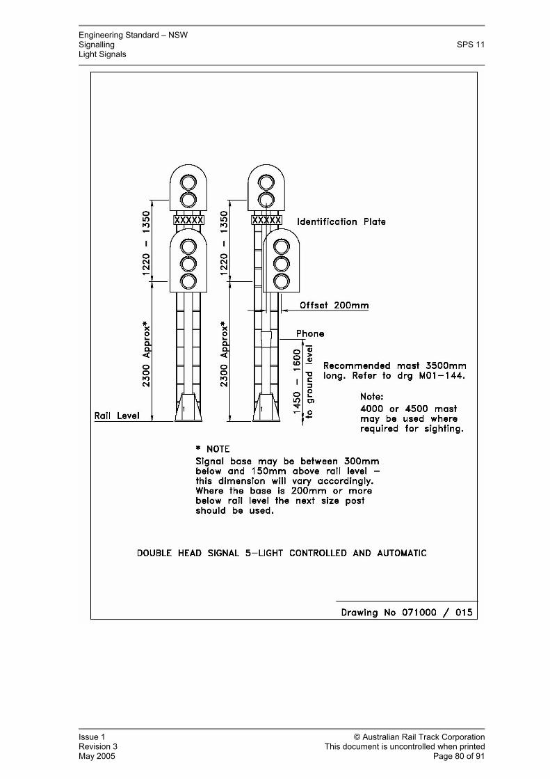
Engineering Standard – NSW Signalling SPS 11 Light Signals
Issue 1 © Australian Rail Track Corporation Revision 3 This document is uncontrolled when printed May 2005 Page 80 of 91

Engineering Standard – NSW Signalling SPS 11 Light Signals
Issue 1 © Australian Rail Track Corporation Revision 3 This document is uncontrolled when printed May 2005 Page 81 of 91

Engineering Standard – NSW Signalling SPS 11 Light Signals
Issue 1 © Australian Rail Track Corporation Revision 3 This document is uncontrolled when printed May 2005 Page 82 of 91

Engineering Standard – NSW Signalling SPS 11 Light Signals
Issue 1 © Australian Rail Track Corporation Revision 3 This document is uncontrolled when printed May 2005 Page 83 of 91

Engineering Standard – NSW Signalling SPS 11 Light Signals
Issue 1 © Australian Rail Track Corporation Revision 3 This document is uncontrolled when printed May 2005 Page 84 of 91

Engineering Standard – NSW Signalling SPS 11 Light Signals
Issue 1 © Australian Rail Track Corporation Revision 3 This document is uncontrolled when printed May 2005 Page 85 of 91

Engineering Standard – NSW Signalling SPS 11 Light Signals
Issue 1 © Australian Rail Track Corporation Revision 3 This document is uncontrolled when printed May 2005 Page 86 of 91

Engineering Standard – NSW Signalling SPS 11 Light Signals
Issue 1 © Australian Rail Track Corporation Revision 3 This document is uncontrolled when printed May 2005 Page 87 of 91

Engineering Standard – NSW Signalling SPS 11 Light Signals
Issue 1 © Australian Rail Track Corporation Revision 3 This document is uncontrolled when printed May 2005 Page 88 of 91
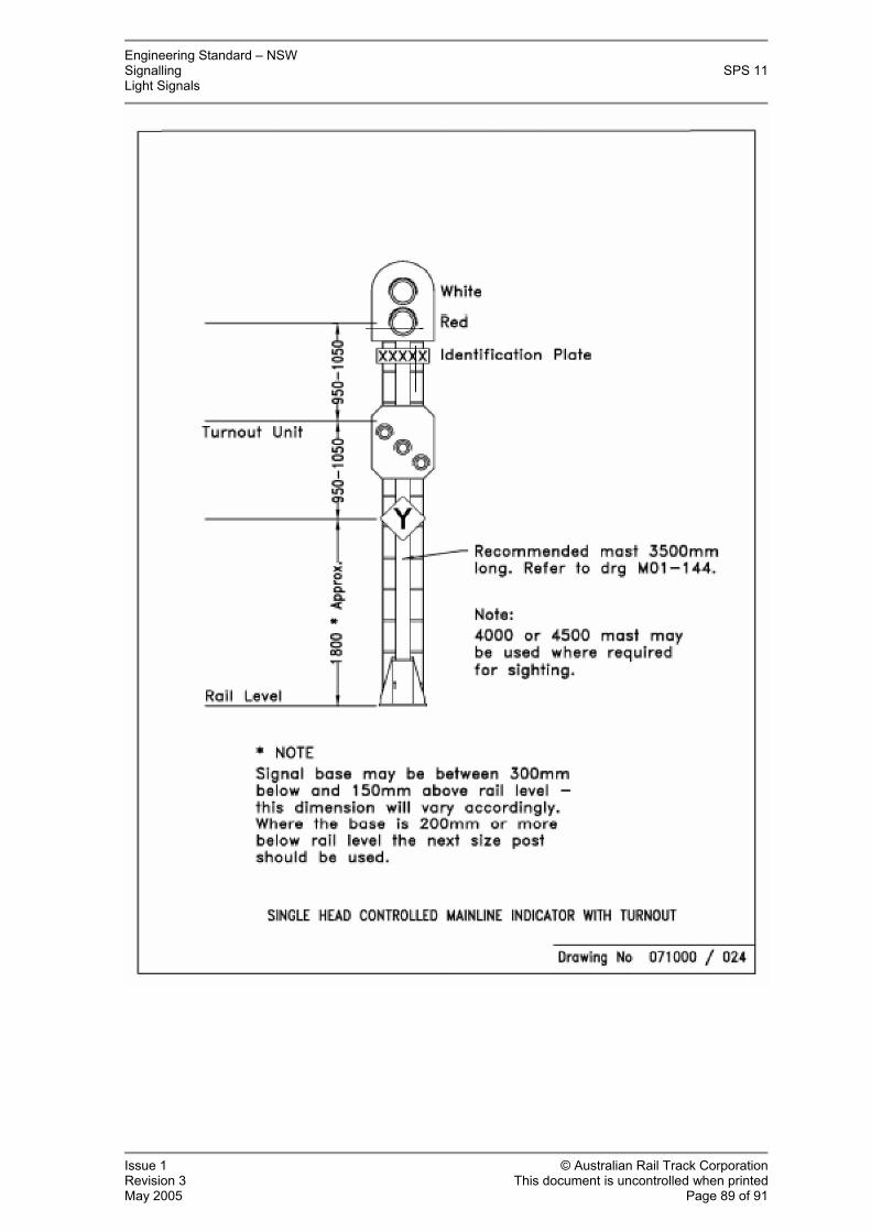
Engineering Standard – NSW Signalling SPS 11 Light Signals
Issue 1 © Australian Rail Track Corporation Revision 3 This document is uncontrolled when printed May 2005 Page 89 of 91

Engineering Standard – NSW Signalling SPS 11 Light Signals
Issue 1 © Australian Rail Track Corporation Revision 3 This document is uncontrolled when printed May 2005 Page 90 of 91

Engineering Standard – NSW Signalling SPS 11 Light Signals
Issue 1 © Australian Rail Track Corporation Revision 3 This document is uncontrolled when printed May 2005 Page 91 of 91
Appendix A: Capacitive Coupling: Testing Procedure
Testing for Capacitive Coupling: Relay Interlocking
False illumination of LED signals due to capacitive coupling is dependent on the voltage coupled in the cable and the input impedance of the LED light.
Lights are required to be tested and a conformance statement as to maximum safe operating distance based on the capacitive values listed below, is to provided as part of the required documentation to be submitted when lights are assessed for type approval.
In testing the distance limitations of LED lights related to capacitive coupling in cables for conformance to this specification; capacitive coupling may be simulated by using various values of 240Vac mains rated capacitors in series with the LED light being tested, documenting what happens in terms of light being emitted.
ARTC commonly used signal cables are multi-core control and Dekoron (brand name) type twisted pair. The following fixed distance capacitance values are to be used when assessing and testing LED lights for compliance:
- 235nF = 0.75km
- 313nF = 1 km
- 470nF = 1.5km
- 627nF = 2km
The required nominal test voltage is 115Vac.
Example 1: If for example a value of 0.23uF is reached just prior to some individual LEDs beginning to glow, then the maximum cable distance permitted would be less than the minimum 750m distance value. Thus the light would not conform to the minimum requirements.
Example 2: If for example a value of 0.28uF is reached just prior to some individual LEDs beginning to glow, then the maximum cable distance permitted would be the 750m distance value. Thus the light would conform to the minimum requirements.