disassembly and assembly instructions for liquid ring ... · pdf file2 disassembly and...
TRANSCRIPT
1
DISASSEMBLY AND ASSEMBLY
INSTRUCTIONS FOR LIQUID RING VACUUM PUMPS
WITH MECHANICAL SEALS
TRH - TRS 32 to 125 TRV 65
Disassembly and assembly instructions for liquid ring vacuum pumps with mechanical seals 2
INTRODUCTION
These instructions are for the maintenance staff in case of repair for the following pumps: TRHE 32-20 to 60 TRSE 32 TRVA 65 TRHC 40-110 TRSC 40 TRHE 40-110 TRSE 40 TRHC 40-140 & 190 TRSC 50 TRHE 40-140 & 190 TRSE 50 TRHB 50 TRSB 100 TRHC 80 TRSC 100 TRHE 100 TRSE 125
These instructions are supplied and integrated with the manual of “INSTALLATION, OPERATION AND MAINTENANCE INSTRUCTIONS FOR LIQUID RING VACUUM PUMPS”. They provide a reference for safe operation, installation, maintenance and repairing of the pumps. Prior to working on the pump it is recommended to follow the instructions of safety listed in chapters 2 and 15 of the above manual, and is absolutely important to: - wear safety clothing, hard hat, safety shoes, safety eye glasses - disconnect the electrical power - close suction valves and service liquid valves - remove pump from installation without damaging other system components - assume all safety measures if pump has been handling dangerous fluids - drain pump casings through the draining connections and flush the pump with clean liquid, if required. The pump type and part number are stamped on the pump nameplate, it is always required to refer to this number when ordering spare parts or when requesting further technical information. Assembly and disassembly requires a particular knowledge of the operations to be carried out: therefore, please read these instructions carefully and if the information given is not sufficient and/or easily understandable, it is recommended to send the pump to POMPETRAVAINI or its closest authorised representative. Any pump repairs and/or system work carried out by others will not be guaranteed by POMPETRAVAINI. NOTE: VDMA numbers identify all pump components. Refer to parts list in chapter 9 and to the section drawings in
chapter 10. All drawings are schematic only and are not certified for construction. For further information please consult POMPETRAVAINI or its closest representative. Torque values of various bolt sizes and tie-bolts are listed on fig. 34 and tab. 13.
INDEX 1 - Disassembly to replace bearings and/or mechanical seals 2 - Mechanical seal assembly 2.1 - Assembly of the stationary part in the bearing housing 2.2 - Assembly of the rotating part on the shaft 3 - Bearing assembly
3.1 - Securing the bearings (not for pumps series 32) 4 - Bearing lubrication 5 - Total pump disassembly 6 - Machining the pump parts 6.1 - Typical schematics for machining to restore clearances - Pumps series “TRH” 6.2 - Typical schematics for machining to restore clearances - Pumps series “TRS - TRV” 7 - Pump assembly
7.1 - Pumps series ”TRHE & TRSE 32” 7.2 - Pumps series “TRH 40 to 100 - TRS 40 to 125 - TRV 65”
8 - Recommended spare parts 9 - Parts list 10 - Typical sectional drawings In preparing this manual, every possible effort has been made to help the customer and operator with the proper installation and operation of the pump. Should you find errors, misunderstandings or discrepancies please do not hesitate to bring them to our attention.
Disassembly and assembly instructions for liquid ring vacuum pumps with mechanical seals 3
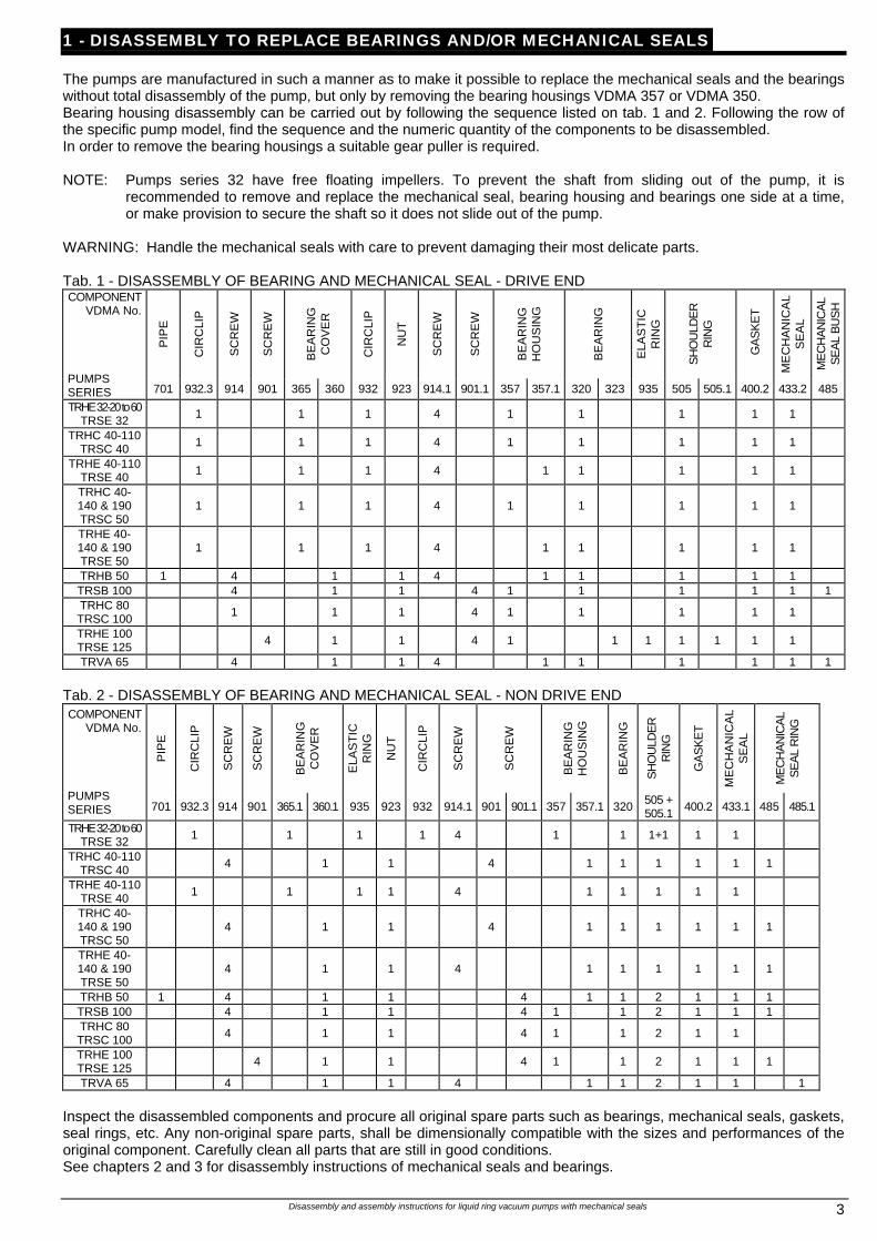
1 - DISASSEMBLY TO REPLACE BEARINGS AND/OR MECHANICAL SEALS The pumps are manufactured in such a manner as to make it possible to replace the mechanical seals and the bearings without total disassembly of the pump, but only by removing the bearing housings VDMA 357 or VDMA 350. Bearing housing disassembly can be carried out by following the sequence listed on tab. 1 and 2. Following the row of the specific pump model, find the sequence and the numeric quantity of the components to be disassembled. In order to remove the bearing housings a suitable gear puller is required. NOTE: Pumps series 32 have free floating impellers. To prevent the shaft from sliding out of the pump, it is
recommended to remove and replace the mechanical seal, bearing housing and bearings one side at a time, or make provision to secure the shaft so it does not slide out of the pump.
WARNING: Handle the mechanical seals with care to prevent damaging their most delicate parts. Tab. 1 - DISASSEMBLY OF BEARING AND MECHANICAL SEAL - DRIVE END
PIP
E
CIR
CLI
P
SC
RE
W
SC
RE
W
BE
AR
ING
C
OV
ER
CIR
CLI
P
NU
T
SC
RE
W
SC
RE
W
BE
AR
ING
H
OU
SIN
G
BE
AR
ING
ELA
ST
IC
RIN
G
SH
OU
LDE
R
RIN
G
GA
SK
ET
ME
CH
AN
ICA
L S
EA
L
ME
CH
AN
ICA
L S
EA
L B
US
H COMPONENT
VDMA No.
PUMPS SERIES 701 932.3 914 901 365 360 932 923 914.1 901.1 357 357.1 320 323 935 505 505.1 400.2 433.2 485
TRHE 32-20 to 60 TRSE 32 1 1 1 4 1 1 1 1 1
TRHC 40-110 TRSC 40 1 1 1 4 1 1 1 1 1
TRHE 40-110 TRSE 40 1 1 1 4 1 1 1 1 1
TRHC 40- 140 & 190 TRSC 50
1 1 1 4 1 1 1 1 1
TRHE 40- 140 & 190 TRSE 50
1 1 1 4 1 1 1 1 1
TRHB 50 1 4 1 1 4 1 1 1 1 1 TRSB 100 4 1 1 4 1 1 1 1 1 1 TRHC 80 TRSC 100 1 1 1 4 1 1 1 1 1
TRHE 100 TRSE 125 4 1 1 4 1 1 1 1 1 1 1
TRVA 65 4 1 1 4 1 1 1 1 1 1 Tab. 2 - DISASSEMBLY OF BEARING AND MECHANICAL SEAL - NON DRIVE END
PIP
E
CIR
CLI
P
SC
RE
W
SC
RE
W
BE
AR
ING
C
OV
ER
ELA
ST
IC
RIN
G
NU
T
CIR
CLI
P
SC
RE
W
SC
RE
W
BE
AR
ING
H
OU
SIN
G
BE
AR
ING
SH
OU
LDE
R
RIN
G
GA
SK
ET
ME
CH
AN
ICA
L S
EA
L
ME
CH
AN
ICA
L S
EA
L R
ING
COMPONENT VDMA No.
PUMPS SERIES 701 932.3 914 901 365.1 360.1 935 923 932 914.1 901 901.1 357 357.1 320 505 +
505.1 400.2 433.1 485 485.1
TRHE 32-20 to 60 TRSE 32 1 1 1 1 4 1 1 1+1 1 1
TRHC 40-110 TRSC 40 4 1 1 4 1 1 1 1 1 1
TRHE 40-110 TRSE 40 1 1 1 1 4 1 1 1 1 1
TRHC 40- 140 & 190 TRSC 50
4 1 1 4 1 1 1 1 1 1
TRHE 40- 140 & 190 TRSE 50
4 1 1 4 1 1 1 1 1 1
TRHB 50 1 4 1 1 4 1 1 2 1 1 1 TRSB 100 4 1 1 4 1 1 2 1 1 1 TRHC 80 TRSC 100 4 1 1 4 1 1 2 1 1
TRHE 100 TRSE 125 4 1 1 4 1 1 2 1 1 1
TRVA 65 4 1 1 4 1 1 2 1 1 1 Inspect the disassembled components and procure all original spare parts such as bearings, mechanical seals, gaskets, seal rings, etc. Any non-original spare parts, shall be dimensionally compatible with the sizes and performances of the original component. Carefully clean all parts that are still in good conditions. See chapters 2 and 3 for disassembly instructions of mechanical seals and bearings.
Disassembly and assembly instructions for liquid ring vacuum pumps with mechanical seals 4
2 - MECHANICAL SEAL ASSEMBLY NOTE: The mechanical seals mounted on the pumps are of standard type according to DIN 24960/K (shorter working
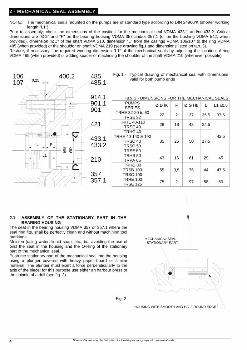
length "L1"). Prior to assembly, check the dimensions of the cavities for the mechanical seal VDMA 433.1 and/or 433.2. Critical dimensions are "ØG" and "F" on the bearing housing VDMA 357 and/or 357.1 (or on the bushing VDMA 542, when provided), dimension "ØD" of the shaft VDMA 210, dimension "L" from the casings VDMA 106/107 to the ring VDMA 485 (when provided) or the shoulder on shaft VDMA 210 (see drawing fig.1 and dimensions listed on tab. 3). Restore, if necessary, the required working dimension “L1” of the mechanical seals by adjusting the location of ring VDMA 485 (when provided) or adding spacer or machining the shoulder of the shaft VDMA 210 (whenever possible).
Fig. 1 - Typical drawing of mechanical seal with dimensions valid for both pump ends
Tab. 3 - DIMENSIONS FOR THE MECHANICAL SEALS PUMPS SERIES Ø D h6 F Ø G H8 L L1 ±0,5
TRHE 32-20 to 60 TRSE 32 22 2 37 35,5 37,5
TRHE 40-110 TRSE 40 28 18 43 24,5
TRHC 40 TRHE 40-140 & 190
TRSC 40 TRSC 50 TRSE 50
35 25 50 17,5 42,5
TRHB 50 TRVA 65 43 16 61 29 45
TRHC 80 TRSB 100 TRSC 100
55 3,5 75 44 47,5
TRHE 100 TRSE 125 75 2 97 58 60
L
L1
F
ØG
ØD
357.1357
433.1433.2
210
0,25106107
400.2
914.1901.1
421
901
485.1485
2.1 - ASSEMBLY OF THE STATIONARY PART IN THE
BEARING HOUSING The seat in the bearing housing VDMA 357 or 357.1 where the seal ring fits, shall be perfectly clean and without machining tool markings. Moisten (using water, liquid soap, etc., but avoiding the use of oils) the seat in the housing and the O-Ring of the stationary part of the mechanical seal. Push the stationary part of the mechanical seal into the housing using a plunger covered with heavy paper board or similar material. The plunger must exert a force perpendicularly to the axis of the piece; for this purpose use either an harbour press or the spindle of a drill (see fig. 2).
Fig. 2
MECHANICAL SEAL - STATIONARY PART -
HOUSING WITH SMOOTH AND HALF-ROUND EDGE
Disassembly and assembly instructions for liquid ring vacuum pumps with mechanical seals 5
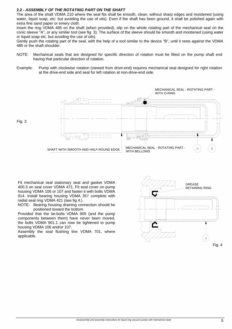
2.2 - ASSEMBLY OF THE ROTATING PART ON THE SHAFT The area of the shaft VDMA 210 where the seal fits shall be smooth, clean, without sharp edges and moistened (using water, liquid soap, etc: but avoiding the use of oils). Even if the shaft has been ground, it shall be polished again with extra fine sand paper or emery cloth. Insert the ring VDMA 485 on the shaft (when provided), slip on the whole rotating part of the mechanical seal on the conic sleeve "A", or any similar tool (see fig. 3). The surface of the sleeve should be smooth and moistened (using water or liquid soap etc. but avoiding the use of oils). Gently push the rotating part of the seal, with the help of a tool similar to the device "B", until it rests against the VDMA 485 or the shaft shoulder. NOTE: Mechanical seals that are designed for specific direction of rotation must be fitted on the pump shaft end
having that particular direction of rotation. Example: Pump with clockwise rotation (viewed from drive-end) requires mechanical seal designed for right rotation
at the drive-end side and seal for left rotation at non-drive-end side. Fig. 3
Fit mechanical seal stationary seat and gasket VDMA 400.3 on seal cover VDMA 471. Fit seal cover on pump housing VDMA 106 or 107 and fasten it with bolts VDMA 914. Install bearing housing VDMA 357 complete with radial seal ring VDMA 421 (see fig 4.). NOTE: Bearing housing draining connection should be
positioned toward the bottom. Provided that the tie-bolts VDMA 905 (and the pump components between them) have never been moved, the bolts VDMA 901.1 can now be tightened to pump housing VDMA 106 and/or 107. Assembly the seal flushing line VDMA 701, where applicable.
Fig. 4
MECHANICAL SEAL - ROTATING PART - WITH O-RING
SHAFT WITH SMOOTH AND HALF-ROUND EDGE MECHANICAL SEAL - ROTATING PART -
WITH BELLOWS
GREASE RETAINING RING
Disassembly and assembly instructions for liquid ring vacuum pumps with mechanical seals 6
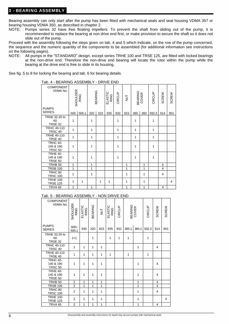
3 - BEARING ASSEMBLY Bearing assembly can only start after the pump has been fitted with mechanical seals and seal housing VDMA 357 or bearing housing VDMA 350, as described in chapter 2. NOTE: Pumps series 32 have free floating impellers. To prevent the shaft from sliding out of the pump, it is
recommended to replace the bearing at non drive end first, or make provision to secure the shaft so it does not slide out of the pump.
Proceed with the assembly following the steps given on tab. 4 and 5 which indicate, on the row of the pump concerned, the sequence and the numeric quantity of the components to be assembled (for additional information see instructions on the following pages). NOTE: All pumps in the “STANDARD” design, except series TRHE 100 and TRSE 125, are fitted with locked bearings
at the non-drive end. Therefore the non-drive end bearing will locate the rotor within the pump while the bearing at the drive end is free to slide in its housing.
See fig. 5 to 8 for locking the bearing and tab. 6 for bearing details.
Tab. 4 - BEARING ASSEMBLY - DRIVE END
SH
OU
LDE
R
RIN
G
BE
AR
ING
ELA
ST
IC
RIN
G
CIR
CLI
P
NU
T
BE
AR
ING
C
OV
ER
CIR
CLI
P
SC
RE
W
SC
RE
W
COMPONENT VDMA No.
PUMPS SERIES 505 505.1 320 323 935 932 923 365 360 932.3 914 901
TRHE 32-20 to 60
TRSE 32 1 1 1 1 1
TRHC 40-110 TRSC 40 1 1 1 1 1
TRHE 40-110 TRSE 40 1 1 1 1 1
TRHC 40- 140 & 190 TRSC 50
1 1 1 1 1
TRHE 40- 140 & 190 TRSE 50
1 1 1 1 1
TRHB 50 1 1 1 1 4 TRSB 100 1 1 1 1 4 TRHC 80 TRSC 100 1 1 1 1 4
TRHE 100 TRSE 125 1 1 1 1 1 1 4
TRVA 65 1 1 1 1 4
Tab. 5 - BEARING ASSEMBLY - NON DRIVE END
SH
OU
LDE
R
RIN
G
ELA
ST
IC
RIN
G
BE
AR
ING
NU
T
ELA
ST
IC
RIN
G
CIR
CLI
P
BE
AR
ING
C
OV
ER
CIR
CLI
P
SC
RE
W
SC
RE
W
COMPONENT VDMA No.
PUMPS SERIES
505+ 505.1 935 320 923 935 932 365.1 360.1 932.3 914 901
TRHE 32-20 to 60
TRSE 32 1+1 1 1 1 1 1
TRHC 40-110 TRSC 40 1 1 1 1 1 4
TRHE 40-110 TRSE 40 1 1 1 1 1 1 1
TRHC 40- 140 & 190 TRSC 50
1 1 1 1 1 4
TRHE 40- 140 & 190 TRSE 50
1 1 1 1 1 4
TRHB 50 2 1 1 1 1 4 TRSB 100 2 1 1 1 1 4 TRHC 80 TRSC 100 2 1 1 1 1 4
TRHE 100 TRSE 125 2 1 1 1 1 4
TRVA 65 2 1 1 1 1 4
Disassembly and assembly instructions for liquid ring vacuum pumps with mechanical seals 7
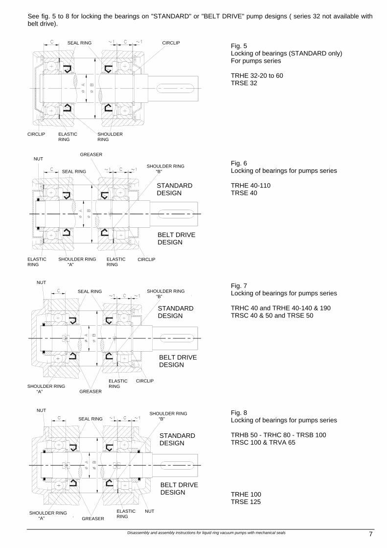
See fig. 5 to 8 for locking the bearings on "STANDARD" or "BELT DRIVE" pump designs ( series 32 not available with belt drive).
Fig. 5 Locking of bearings (STANDARD only) For pumps series TRHE 32-20 to 60 TRSE 32
Fig. 6 Locking of bearings for pumps series TRHE 40-110 TRSE 40
Fig. 7 Locking of bearings for pumps series TRHC 40 and TRHE 40-140 & 190 TRSC 40 & 50 and TRSE 50
Fig. 8 Locking of bearings for pumps series TRHB 50 - TRHC 80 - TRSB 100 TRSC 100 & TRVA 65 TRHE 100 TRSE 125
NUT
GREASER
BELT DRIVE DESIGN
SHOULDER RING “B”
STANDARD DESIGN
SEAL RING
ELASTIC RING
SHOULDER RING “A”
ELASTIC RING
CIRCLIP
ELASTIC RING
SHOULDER RING “A”
SHOULDER RING “B”
STANDARD DESIGN
BELT DRIVE DESIGN
GREASER
NUT
NUT
SEAL RING
SEAL RING
ELASTIC RING
CIRCLIP SHOULDER RING
CIRCLIP
NUT
GREASER
BELT DRIVE DESIGN
SHOULDER RING “B”
STANDARD DESIGN
SEAL RING
SHOULDER RING “A”
ELASTIC RING
CIRCLIP
Disassembly and assembly instructions for liquid ring vacuum pumps with mechanical seals 8
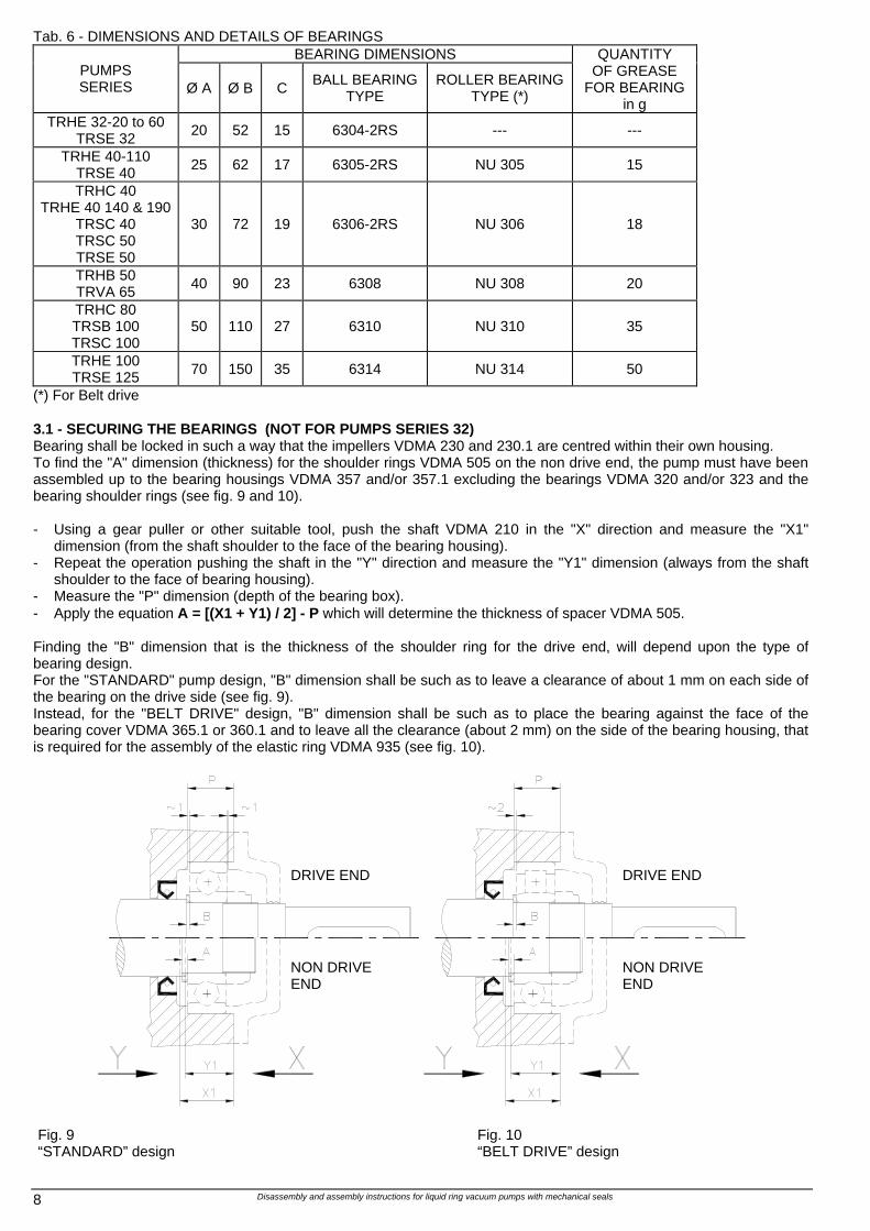
Tab. 6 - DIMENSIONS AND DETAILS OF BEARINGS BEARING DIMENSIONS
PUMPS SERIES Ø A Ø B C BALL BEARING
TYPE ROLLER BEARING
TYPE (*)
QUANTITY OF GREASE
FOR BEARING in g
TRHE 32-20 to 60 TRSE 32 20 52 15 6304-2RS --- ---
TRHE 40-110 TRSE 40 25 62 17 6305-2RS NU 305 15
TRHC 40 TRHE 40 140 & 190
TRSC 40 TRSC 50 TRSE 50
30 72 19 6306-2RS NU 306 18
TRHB 50 TRVA 65 40 90 23 6308 NU 308 20
TRHC 80 TRSB 100 TRSC 100
50 110 27 6310 NU 310 35
TRHE 100 TRSE 125 70 150 35 6314 NU 314 50
(*) For Belt drive 3.1 - SECURING THE BEARINGS (NOT FOR PUMPS SERIES 32) Bearing shall be locked in such a way that the impellers VDMA 230 and 230.1 are centred within their own housing. To find the "A" dimension (thickness) for the shoulder rings VDMA 505 on the non drive end, the pump must have been assembled up to the bearing housings VDMA 357 and/or 357.1 excluding the bearings VDMA 320 and/or 323 and the bearing shoulder rings (see fig. 9 and 10). - Using a gear puller or other suitable tool, push the shaft VDMA 210 in the "X" direction and measure the "X1"
dimension (from the shaft shoulder to the face of the bearing housing). - Repeat the operation pushing the shaft in the "Y" direction and measure the "Y1" dimension (always from the shaft
shoulder to the face of bearing housing). - Measure the "P" dimension (depth of the bearing box). - Apply the equation A = [(X1 + Y1) / 2] - P which will determine the thickness of spacer VDMA 505. Finding the "B" dimension that is the thickness of the shoulder ring for the drive end, will depend upon the type of bearing design. For the "STANDARD" pump design, "B" dimension shall be such as to leave a clearance of about 1 mm on each side of the bearing on the drive side (see fig. 9). Instead, for the "BELT DRIVE" design, "B" dimension shall be such as to place the bearing against the face of the bearing cover VDMA 365.1 or 360.1 and to leave all the clearance (about 2 mm) on the side of the bearing housing, that is required for the assembly of the elastic ring VDMA 935 (see fig. 10).
Fig. 9 “STANDARD” design
Fig. 10 “BELT DRIVE” design
DRIVE END DRIVE END
NON DRIVE END
NON DRIVE END
Disassembly and assembly instructions for liquid ring vacuum pumps with mechanical seals 9
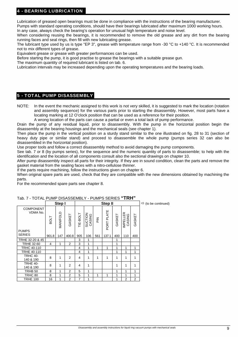
4 - BEARING LUBRICATION Lubrication of greased open bearings must be done in compliance with the instructions of the bearing manufacturer. Pumps with standard operating conditions, should have their bearings lubricated after maximum 1000 working hours. In any case, always check the bearing’s operation for unusual high temperature and noise level. When considering reusing the bearings, it is recommended to remove the old grease and any dirt from the bearing running faces and seal rings, then fill with new lubricating grease. The lubricant type used by us is type "EP 3", grease with temperature range from -30 °C to +140 °C. It is recommended not to mix different types of grease. Equivalent grease or grease with greater performances can be used. Before starting the pump, it is good practise to grease the bearings with a suitable grease gun. The maximum quantity of required lubricant is listed on tab. 6. Lubrication intervals may be increased depending upon the operating temperatures and the bearing loads. 5 - TOTAL PUMP DISASSEMBLY NOTE: In the event the mechanic assigned to this work is not very skilled, it is suggested to mark the location (rotation
and assembly sequence) for the various parts prior to starting the disassembly. However, most parts have a locating marking at 12 O’clock position that can be used as a reference for their position. A wrong location of the parts can cause a partial or even a total lack of pump performance.
Drain the pump of any residual liquid, prior to disassembly. With the pump in the horizontal position begin the disassembly at the bearing housings and the mechanical seals (see chapter 1). Then place the pump in the vertical position on a sturdy stand similar to the one illustrated on fig. 28 to 31 (section of heavy duty pipe or similar stand) and proceed to disassemble the whole pump (pumps series 32 can also be disassembled in the horizontal position). Use proper tools and follow a correct disassembly method to avoid damaging the pump components. See tab. 7 or 8 (by pumps series), for the sequence and the numeric quantity of parts to disassemble; to help with the identification and the location of all components consult also the sectional drawings on chapter 10. After pump disassembly inspect all parts for their integrity. If they are in sound condition, clean the parts and remove the gasket material from the sealing faces with a nitro-cellulose thinner. If the parts require machining, follow the instructions given on chapter 6. When original spare parts are used, check that they are compatible with the new dimensions obtained by machining the parts. For the recommended spare parts see chapter 8. Tab. 7 - TOTAL PUMP DISASSEMBLY - PUMPS SERIES “TRH”
Step I Step II ð (to be continued)
BO
LT
MA
NIF
OLD
GA
SK
ET
TIE
-BO
LT
SU
CT
ION
C
AS
ING
PIN
PO
RT
PLA
TE
GA
SK
ET
IMP
ELL
ER
C
AS
ING
GA
SK
ET
COMPONENT VDMA No.
PUMPS SERIES 901.8 147 400.8 905 106 561 137.1 400 110 400 TRHE 32-20 & 45 3 1 1
TRHE 32-60 4 1 2 3 1 1 TRHC 40-110 4 1 1 1 1 1 1 TRHE 40-110 4 1 1 1 1
TRHC 40- 140 & 190 8 1 2 4 1 1 1 1 1 1
TRHE 40- 140 & 190 8 1 2 4 1 1 1 1
TRHB 50 8 1 2 5 1 1 1 1 TRHC 80 8 1 2 5 1 1 1 1 1 1 TRHE 100 16 1 2 7 1 1 2 2
Disassembly and assembly instructions for liquid ring vacuum pumps with mechanical seals 10
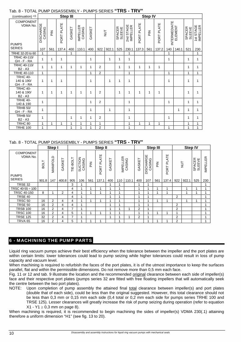
Tab. 8 - TOTAL PUMP DISASSEMBLY - PUMPS SERIES “TRS - TRV” (continuation) ð Step III Step IV
DIS
CH
AR
GE
C
AS
ING
PIN
PO
RT
PLA
TE
GA
SK
ET
IMP
ELL
ER
C
AS
ING
GA
SK
ET
NU
T
SP
AC
ER
S
LEE
VE
2nd
ST
AG
E
IMP
ELL
ER
PO
RT
PLA
TE
PIN
PO
RT
PLA
TE
INT
ER
ME
DIA
TE
E
LEM
EN
T
SP
AC
ER
S
LEE
VE
1st S
TA
GE
IM
PE
LLE
R
COMPONENT VDMA No.
PUMPS SERIES 107 561 137.4 400 110.1 400 922 922.1 525 230.1 137.3 561 137.2 140 140.1 521 230 TRHE 32-20 to 60 1 1 1 1 1
TRHC 40-110/ GH - F - RA 1 1 1 1 1 1 1 1 1 1
TRHC 40-110/ B2 - A3 1 1 1 1 1 1 2 1 1 1 1 1 1 1
TRHE 40-110 1 1 2 1 1 1 1 TRHC 40- 140 & 190/ GH - F - RA
1 1 1 1 1 1 1 1 1 1
TRHC 40- 140 & 190/
B2 - A3 1 1 1 1 1 1 2 1 1 1 1 1 1 1
TRHE 40- 140 & 190 1 1 2 1 1 1 1
TRHB 50/ GH - F - RA 1 1 1 1 1 1 1
TRHB 50/ B2 - A3 1 1 1 1 2 1 1 1 1
TRHC 80 1 1 1 1 1 1 1 1 1 1 1 1 1 TRHE 100 1 1 1 1 2 1 1 1 1
Tab. 8 - TOTAL PUMP DISASSEMBLY - PUMPS SERIES “TRS - TRV”
Step I Step II Step III Step IV
BO
LT
MA
NIF
OLD
GA
SK
ET
TIE
-BO
LT
SU
CT
ION
C
AS
ING
PIN
PO
RT
PLA
TE
GA
SK
ET
IMP
ELL
ER
C
AS
ING
GA
SK
ET
DIS
CH
AR
GE
C
AS
ING
PIN
PO
RT
PLA
TE
NU
T
SP
AC
ER
S
LEE
VE
IMP
ELL
ER
COMPONENT VDMA No.
PUMPS SERIES 901.8 147 400.8 905 106 561 137.1 400 110 110.1 400 107 561 137.4 922 922.1 525 230
TRSE 32 3 1 1 1 1 1 1 TRSC 40-55 ÷ 100 4 1 1 1 1 1 1 1 1 1 1 1 1
TRSC 40-150 8 1 2 4 1 1 1 1 1 1 1 1 1 1 1 1 TRSE 40 4 1 1 1 1 1 2 1 TRSC 50 16 2 4 4 1 1 1 1 1 1 1 1 1 1 1 1 TRSE 50 16 2 4 4 1 1 1 1 1 2 1 TRSB 100 16 2 4 7 1 1 1 1 2 1 2 1 TRSC 100 16 2 4 5 1 1 1 1 1 1 1 1 1 1 1 TRSE 125 32 2 4 7 1 1 1 1 2 1 2 1 TRVA 65 16 2 4 5 1 1 1 1 1 1 1 2 1
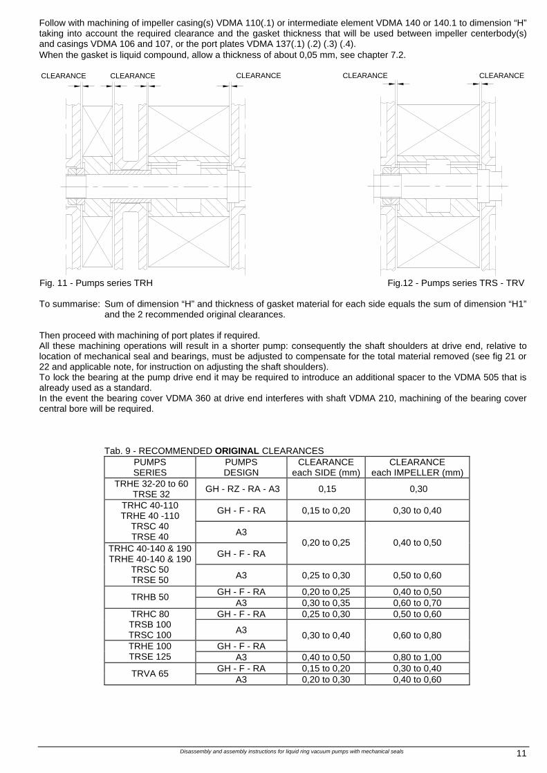
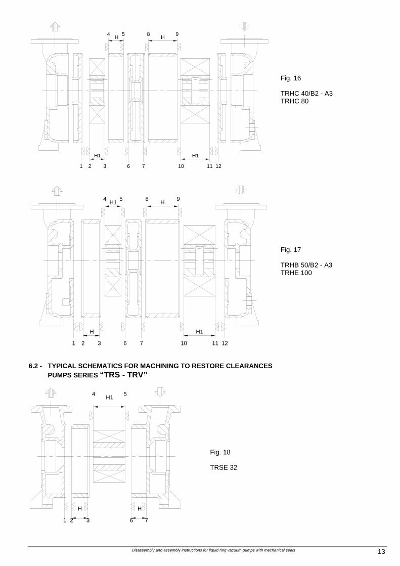
6 - MACHINING THE PUMP PARTS Liquid ring vacuum pumps achieve their best efficiency when the tolerance between the impeller and the port plates are within certain limits: lower tolerances could lead to pump seizing while higher tolerances could result in loss of pump capacity and vacuum level. When machining is required to refurbish the faces of the port plates, it is of the utmost importance to keep the surfaces parallel, flat and within the permissible dimensions. Do not remove more than 0,5 mm each face. Fig. 11 or 12 and tab. 9 illustrate the location and the recommended original clearance between each side of impeller(s) face and their respective port plates (pumps series 32 are fitted with free floating impellers that will automatically seek the centre between the two port plates). NOTE: Upon completion of pump assembly the attained final total clearance between impeller(s) and port plates
(double that of each side), could be less than the original suggested. However, this total clearance should not be less than 0,3 mm or 0,15 mm each side (0,4 total or 0,2 mm each side for pumps series TRHE 100 and TRSE 125). Lesser clearances will greatly increase the risk of pump seizing during operation (refer to equation X1 - Y1 ≥ 0,3 mm on page 8).
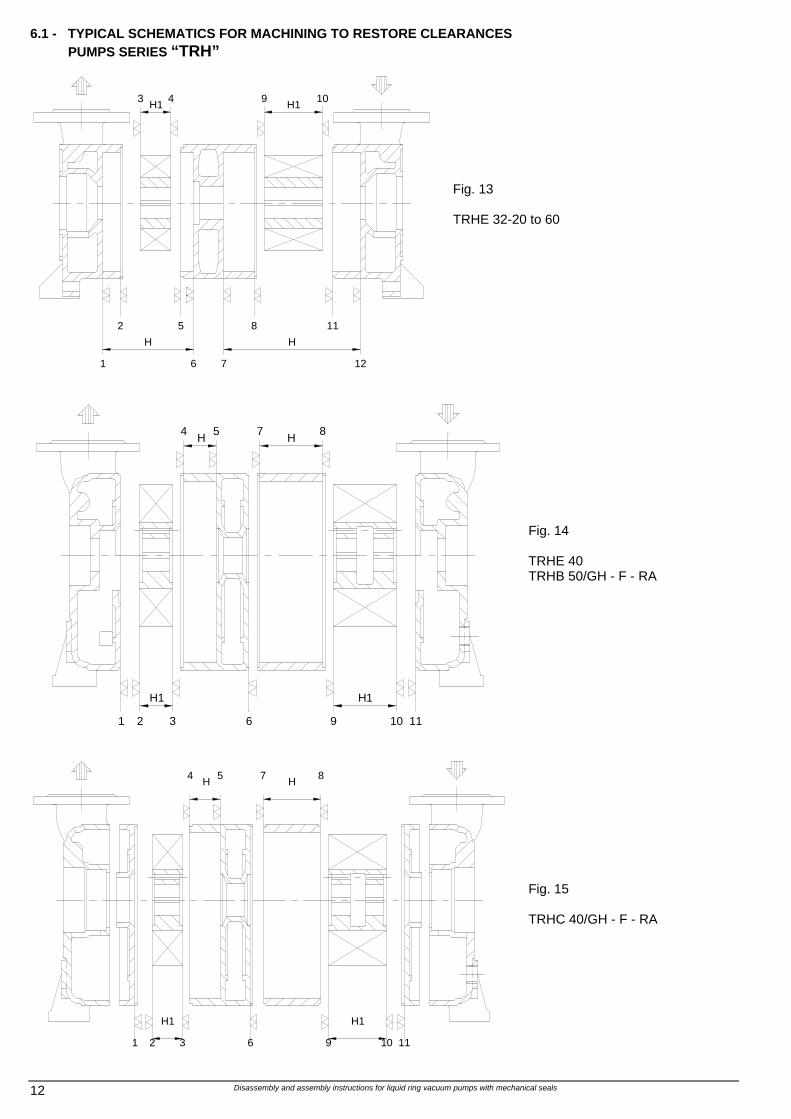
When machining is required, it is recommended to begin machining the sides of impeller(s) VDMA 230(.1) attaining therefore a uniform dimension “H1” (see fig. 13 to 20).
Disassembly and assembly instructions for liquid ring vacuum pumps with mechanical seals 11
Follow with machining of impeller casing(s) VDMA 110(.1) or intermediate element VDMA 140 or 140.1 to dimension “H” taking into account the required clearance and the gasket thickness that will be used between impeller centerbody(s) and casings VDMA 106 and 107, or the port plates VDMA 137(.1) (.2) (.3) (.4). When the gasket is liquid compound, allow a thickness of about 0,05 mm, see chapter 7.2.
Fig. 11 - Pumps series TRH Fig.12 - Pumps series TRS - TRV To summarise: Sum of dimension “H” and thickness of gasket material for each side equals the sum of dimension “H1”
and the 2 recommended original clearances. Then proceed with machining of port plates if required. All these machining operations will result in a shorter pump: consequently the shaft shoulders at drive end, relative to location of mechanical seal and bearings, must be adjusted to compensate for the total material removed (see fig 21 or 22 and applicable note, for instruction on adjusting the shaft shoulders). To lock the bearing at the pump drive end it may be required to introduce an additional spacer to the VDMA 505 that is already used as a standard. In the event the bearing cover VDMA 360 at drive end interferes with shaft VDMA 210, machining of the bearing cover central bore will be required.
Tab. 9 - RECOMMENDED ORIGINAL CLEARANCES PUMPS SERIES
PUMPS DESIGN
CLEARANCE each SIDE (mm)
CLEARANCE each IMPELLER (mm)
TRHE 32-20 to 60 TRSE 32 GH - RZ - RA - A3 0,15 0,30
GH - F - RA 0,15 to 0,20 0,30 to 0,40 TRHC 40-110 TRHE 40 -110
TRSC 40 TRSE 40 A3
GH - F - RA 0,20 to 0,25 0,40 to 0,50
TRHC 40-140 & 190 TRHE 40-140 & 190
TRSC 50 TRSE 50 A3 0,25 to 0,30 0,50 to 0,60
GH - F - RA 0,20 to 0,25 0,40 to 0,50 TRHB 50 A3 0,30 to 0,35 0,60 to 0,70
GH - F - RA 0,25 to 0,30 0,50 to 0,60 TRHC 80 TRSB 100 TRSC 100 A3
GH - F - RA 0,30 to 0,40 0,60 to 0,80
TRHE 100 TRSE 125 A3 0,40 to 0,50 0,80 to 1,00
GH - F - RA 0,15 to 0,20 0,30 to 0,40
TRVA 65 A3 0,20 to 0,30 0,40 to 0,60
CLEARANCE CLEARANCE CLEARANCE CLEARANCE CLEARANCE
Disassembly and assembly instructions for liquid ring vacuum pumps with mechanical seals 12
6.1 - TYPICAL SCHEMATICS FOR MACHINING TO RESTORE CLEARANCES PUMPS SERIES “TRH”
1
H
2
6 7
H
12
5 8 11
43 H1 H19 10
Fig. 13 TRHE 32-20 to 60
1
H1
2 3 96 10
H1
11
4 7H 5 H 8
Fig. 14 TRHE 40 TRHB 50/GH - F - RA
H1
1 2 3
H1
6 9 10 11
4 5H 7 H 8
Fig. 15 TRHC 40/GH - F - RA
Disassembly and assembly instructions for liquid ring vacuum pumps with mechanical seals 13
1
H1
2 3 106 7 11
H1
12
4 5H H8 9
Fig. 16 TRHC 40/B2 - A3 TRHC 80
1
H
2 3 6 7 1110
H1
12
4 9H1 5 8 H
Fig. 17 TRHB 50/B2 - A3 TRHE 100
6.2 - TYPICAL SCHEMATICS FOR MACHINING TO RESTORE CLEARANCES
PUMPS SERIES “TRS - TRV”
1 2
H
3 6
H
7
4 H1 5
Fig. 18 TRSE 32
Disassembly and assembly instructions for liquid ring vacuum pumps with mechanical seals 14
1
H1
4 5 6
2 H 3
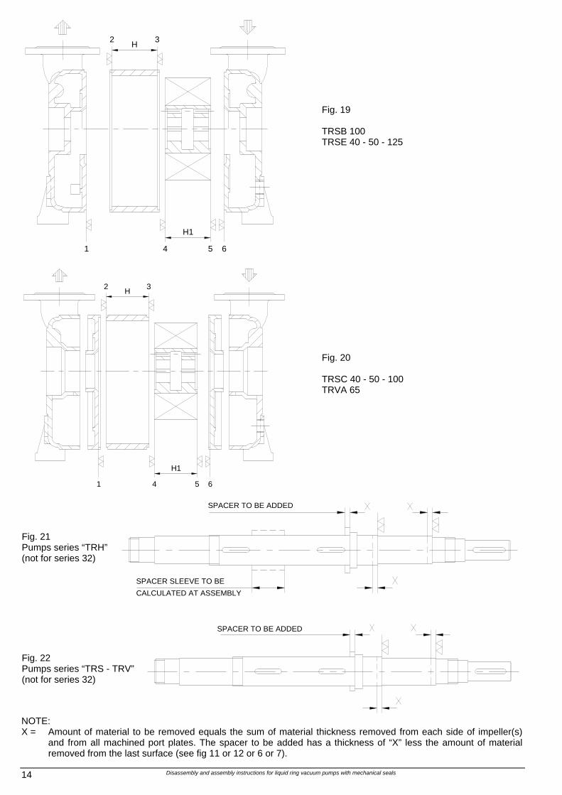
Fig. 19 TRSB 100 TRSE 40 - 50 - 125
1 5
H1
4 6
3H2
Fig. 20 TRSC 40 - 50 - 100 TRVA 65
Fig. 21 Pumps series “TRH” (not for series 32)
Fig. 22 Pumps series “TRS - TRV” (not for series 32)
NOTE: X = Amount of material to be removed equals the sum of material thickness removed from each side of impeller(s)
and from all machined port plates. The spacer to be added has a thickness of “X” less the amount of material removed from the last surface (see fig 11 or 12 or 6 or 7).
SPACER TO BE ADDED
SPACER TO BE ADDED
CALCULATED AT ASSEMBLY
SPACER SLEEVE TO BE
Disassembly and assembly instructions for liquid ring vacuum pumps with mechanical seals 15
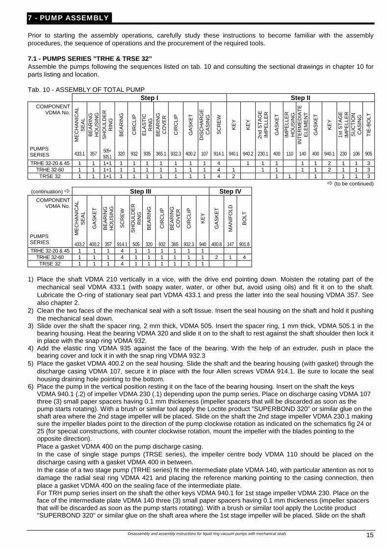
7 - PUMP ASSEMBLY Prior to starting the assembly operations, carefully study these instructions to become familiar with the assembly procedures, the sequence of operations and the procurement of the required tools. 7.1 - PUMPS SERIES ”TRHE & TRSE 32” Assemble the pumps following the sequences listed on tab. 10 and consulting the sectional drawings in chapter 10 for parts listing and location. Tab. 10 - ASSEMBLY OF TOTAL PUMP
Step I Step II
ME
CH
AN
ICA
L S
EA
L B
EA
RIN
G
HO
US
ING
S
HO
ULD
ER
R
ING
BE
AR
ING
CIR
CLI
P
ELA
ST
IC
RIN
G
BE
AR
ING
C
OV
ER
CIR
CLI
P
GA
SK
ET
DIS
CH
AR
GE
C
AS
ING
SC
RE
W
KE
Y
KE
Y
2nd
ST
AG
E
IMP
ELL
ER
GA
SK
ET
IMP
ELL
ER
H
OU
SIN
G
INT
ER
ME
DIA
TE
E
LEM
EN
T
GA
SK
ET
KE
Y
1st S
TA
GE
IM
PE
LLE
R
SU
CT
ION
C
AS
ING
TIE
-BO
LT
COMPONENT VDMA No.
PUMPS SERIES 433.1 357 505+
505.1 320 932 935 365.1 932.3 400.2 107 914.1 940.1 940.2 230.1 400 110 140 400 940.1 230 106 905
TRHE 32-20 & 45 1 1 1+1 1 1 1 1 1 1 1 4 1 1 1 1 1 2 1 1 3 TRHE 32-60 1 1 1+1 1 1 1 1 1 1 1 4 1 1 1 1 1 2 1 1 3
TRSE 32 1 1 1+1 1 1 1 1 1 1 1 4 2 1 1 1 1 1 3 ð (to be continued)
(continuation) ð Step III Step IV
ME
CH
AN
ICA
L S
EA
L
GA
SK
ET
BE
AR
ING
H
OU
SIN
G
SC
RE
W
SH
OU
LDE
R
RIN
G
BE
AR
ING
CIR
CLI
P
BE
AR
ING
C
OV
ER
CIR
CLI
P
KE
Y
GA
SK
ET
MA
NIF
OLD
BO
LT
COMPONENT VDMA No.
PUMPS SERIES 433.2 400.2 357 914.1 505 320 932 365 932.3 940 400.8 147 901.8 TRHE 32-20 & 45 1 1 1 4 1 1 1 1 1 1
TRHE 32-60 1 1 1 4 1 1 1 1 1 1 2 1 4 TRSE 32 1 1 1 4 1 1 1 1 1 1
1) Place the shaft VDMA 210 vertically in a vice, with the drive end pointing down. Moisten the rotating part of the
mechanical seal VDMA 433.1 (with soapy water, water, or other but, avoid using oils) and fit it on to the shaft. Lubricate the O-ring of stationary seal part VDMA 433.1 and press the latter into the seal housing VDMA 357. See also chapter 2.
2) Clean the two faces of the mechanical seal with a soft tissue. Insert the seal housing on the shaft and hold it pushing the mechanical seal down.
3) Slide over the shaft the spacer ring, 2 mm thick, VDMA 505. Insert the spacer ring, 1 mm thick, VDMA 505.1 in the bearing housing. Heat the bearing VDMA 320 and slide it on to the shaft to rest against the shaft shoulder then lock it in place with the snap ring VDMA 932.
4) Add the elastic ring VDMA 935 against the face of the bearing. With the help of an extruder, push in place the bearing cover and lock it in with the snap ring VDMA 932.3
5) Place the gasket VDMA 400.2 on the seal housing. Slide the shaft and the bearing housing (with gasket) through the discharge casing VDMA 107, secure it in place with the four Allen screws VDMA 914.1. Be sure to locate the seal housing draining hole pointing to the bottom.
6) Place the pump in the vertical position resting it on the face of the bearing housing. Insert on the shaft the keys VDMA 940.1 (.2) of impeller VDMA 230 (.1) depending upon the pump series. Place on discharge casing VDMA 107 three (3) small paper spacers having 0.1 mm thickeness (impeller spacers that will be discarded as soon as the pump starts rotating). With a brush or similar tool apply the Loctite product "SUPERBOND 320" or similar glue on the shaft area where the 2nd stage impeller will be placed. Slide on the shaft the 2nd stage impeller VDMA 230.1 making sure the impeller blades point to the direction of the pump clockwise rotation as indicated on the schematics fig 24 or 25 (for special constructions, with counter clockwise rotation, mount the impeller with the blades pointing to the opposite direction). Place a gasket VDMA 400 on the pump discharge casing. In the case of single stage pumps (TRSE series), the impeller centre body VDMA 110 should be placed on the discharge casing with a gasket VDMA 400 in between. In the case of a two stage pump (TRHE series) fit the intermediate plate VDMA 140, with particular attention as not to damage the radial seal ring VDMA 421 and placing the reference marking pointing to the casing connection, then place a gasket VDMA 400 on the sealing face of the intermediate plate.
For TRH pump series insert on the shaft the other keys VDMA 940.1 for 1st stage impeller VDMA 230. Place on the face of the intermediate plate VDMA 140 three (3) small paper spacers having 0.1 mm thickeness (impeller spacers that will be discarded as soon as the pump starts rotating). With a brush or similar tool apply the Loctite product "SUPERBOND 320" or similar glue on the shaft area where the 1st stage impeller will be placed. Slide on the shaft
Disassembly and assembly instructions for liquid ring vacuum pumps with mechanical seals 16
the 1st stage impeller VDMA 230 making sure the impeller blades point to the same direction as those of the 2nd stage impeller VDMA 230.1. Place the suction casing VDMA 106 on the pump.
7) Introduce the three tie-bolts VDMA 905 leaving the nuts finger tight. Place the pump on a flat and horizontal table, align all the pump components and tighten the tie-bolts to 4 kgm (see tab. 13) using a torque wrench.
8) Ascertain that the shaft shoulder is 35,5 mm ± 0,5 mm deep relative to the external face of the suction casing VDMA 106 (see fig. 1 and tab. 3). Lubricate the seal rotating part (with water, soapy water, etc. but not oils) and fit it on the shaft. Lubricate the O-ring on the stationary seal and press this part in the seal housing VDMA 357. NOTE: The seal housing for the drive end side should have threaded holes suitable for the motor lantern, if
required. Clean the two seal faces with a soft tissue, place a gasket VDMA 400 on the seal housing and fit this on to the
suction casing VDMA 106 with the draining hole located at the bottom. Lock the assembly with 4 screws VDMA 914.1.
To prevent moving the impellers (from where they have been glued on the shaft) while mounting the bearing VDMA 320 at the drive end, it is recommended to remove the snap ring VDMA 923.3, the bearing cover VDMA 365.1 and the elastic ring VDMA 935. Place the pump in the vertical position resting the shaft on a spacer (not the bearing housing): In this way the movement of the shaft and consequently the impellers will be prevented.
9) Introduce on the shaft the 2 mm spacer VDMA 505. Fit the heated bearing VDMA 320 on the shaft until it rests against the spacer. Place the snap ring VDMA 932 on the shaft. Install the bearing cover VDMA 365 securing it with the snap ring VDMA 932.3. Fit the coupling key VDMA 940 on the shaft drive end.
At the end of assembly of the drive end, flip the pump over. Re-install the previously removed elastic ring VDMA 935, bearing cover VDMA 365.1 and the snap ring VDMA 932.
In the event the pump requires the manifold VDMA 147, mount this on to the flanges of the suction casing VDMA 106 and discharge casing VDMA 107, with gaskets VDMA 400.8 between the flanges. Secure with flange bolting VDMA 901.8.
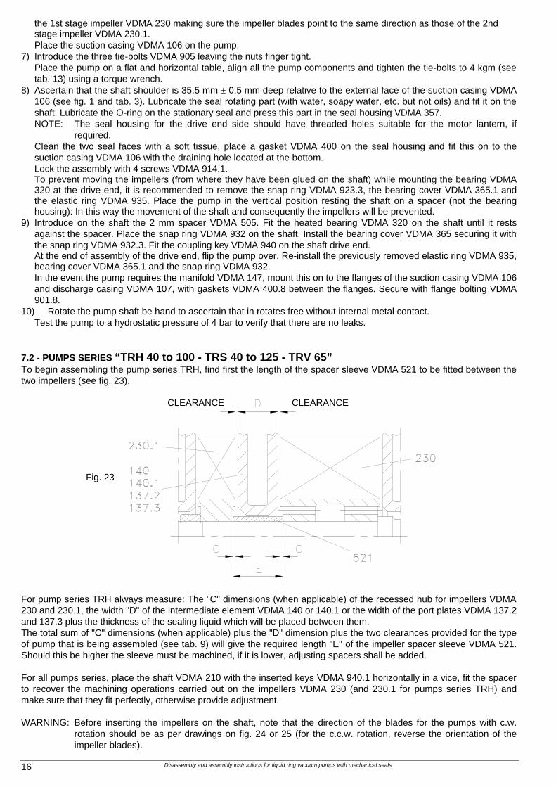
10) Rotate the pump shaft be hand to ascertain that in rotates free without internal metal contact. Test the pump to a hydrostatic pressure of 4 bar to verify that there are no leaks. 7.2 - PUMPS SERIES “TRH 40 to 100 - TRS 40 to 125 - TRV 65” To begin assembling the pump series TRH, find first the length of the spacer sleeve VDMA 521 to be fitted between the two impellers (see fig. 23).
Fig. 23
For pump series TRH always measure: The "C" dimensions (when applicable) of the recessed hub for impellers VDMA 230 and 230.1, the width "D" of the intermediate element VDMA 140 or 140.1 or the width of the port plates VDMA 137.2 and 137.3 plus the thickness of the sealing liquid which will be placed between them. The total sum of "C" dimensions (when applicable) plus the "D" dimension plus the two clearances provided for the type of pump that is being assembled (see tab. 9) will give the required length "E" of the impeller spacer sleeve VDMA 521. Should this be higher the sleeve must be machined, if it is lower, adjusting spacers shall be added. For all pumps series, place the shaft VDMA 210 with the inserted keys VDMA 940.1 horizontally in a vice, fit the spacer to recover the machining operations carried out on the impellers VDMA 230 (and 230.1 for pumps series TRH) and make sure that they fit perfectly, otherwise provide adjustment. WARNING: Before inserting the impellers on the shaft, note that the direction of the blades for the pumps with c.w.
rotation should be as per drawings on fig. 24 or 25 (for the c.c.w. rotation, reverse the orientation of the impeller blades).
CLEARANCE CLEARANCE
Disassembly and assembly instructions for liquid ring vacuum pumps with mechanical seals 17
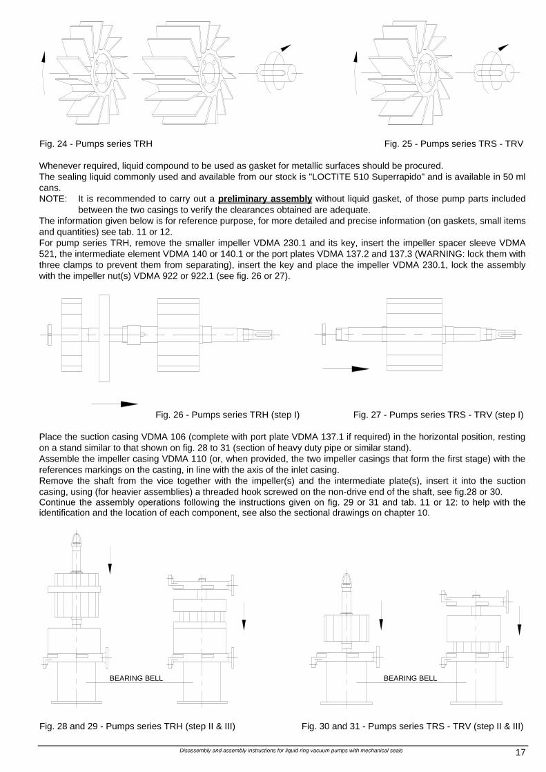
Fig. 24 - Pumps series TRH
Fig. 25 - Pumps series TRS - TRV
Whenever required, liquid compound to be used as gasket for metallic surfaces should be procured. The sealing liquid commonly used and available from our stock is "LOCTITE 510 Superrapido" and is available in 50 ml cans. NOTE: It is recommended to carry out a preliminary assembly without liquid gasket, of those pump parts included
between the two casings to verify the clearances obtained are adequate. The information given below is for reference purpose, for more detailed and precise information (on gaskets, small items and quantities) see tab. 11 or 12. For pump series TRH, remove the smaller impeller VDMA 230.1 and its key, insert the impeller spacer sleeve VDMA 521, the intermediate element VDMA 140 or 140.1 or the port plates VDMA 137.2 and 137.3 (WARNING: lock them with three clamps to prevent them from separating), insert the key and place the impeller VDMA 230.1, lock the assembly with the impeller nut(s) VDMA 922 or 922.1 (see fig. 26 or 27).
Fig. 26 - Pumps series TRH (step I) Fig. 27 - Pumps series TRS - TRV (step I) Place the suction casing VDMA 106 (complete with port plate VDMA 137.1 if required) in the horizontal position, resting on a stand similar to that shown on fig. 28 to 31 (section of heavy duty pipe or similar stand). Assemble the impeller casing VDMA 110 (or, when provided, the two impeller casings that form the first stage) with the references markings on the casting, in line with the axis of the inlet casing. Remove the shaft from the vice together with the impeller(s) and the intermediate plate(s), insert it into the suction casing, using (for heavier assemblies) a threaded hook screwed on the non-drive end of the shaft, see fig.28 or 30. Continue the assembly operations following the instructions given on fig. 29 or 31 and tab. 11 or 12: to help with the identification and the location of each component, see also the sectional drawings on chapter 10.
Fig. 28 and 29 - Pumps series TRH (step II & III)
Fig. 30 and 31 - Pumps series TRS - TRV (step II & III)
BEARING BELL
BEARING BELL
Disassembly and assembly instructions for liquid ring vacuum pumps with mechanical seals 18
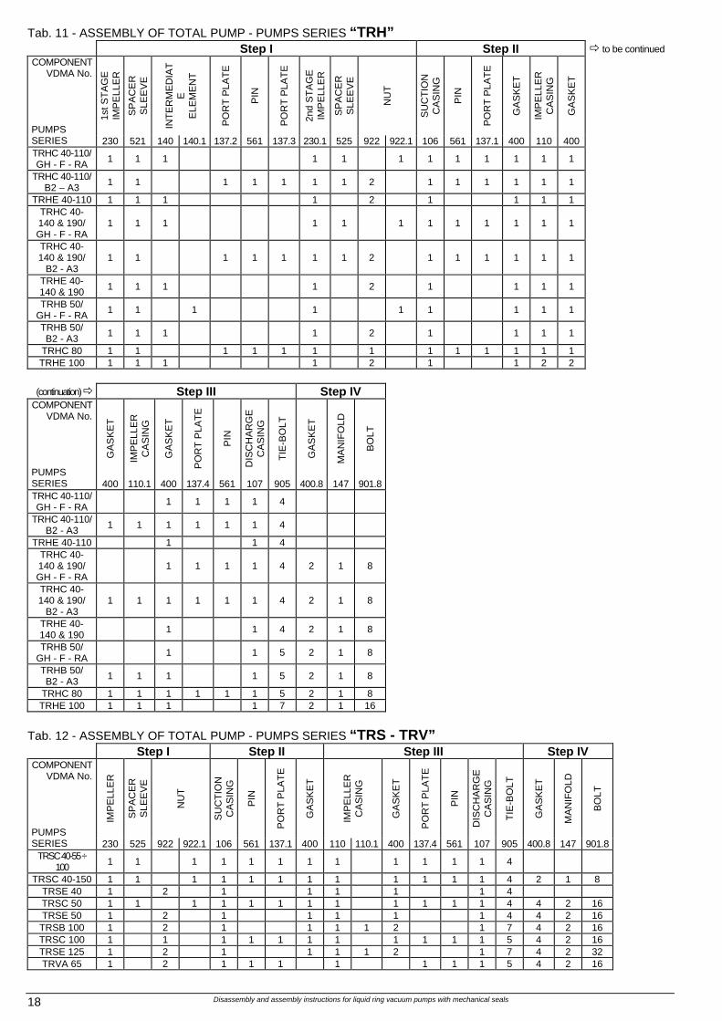
Tab. 11 - ASSEMBLY OF TOTAL PUMP - PUMPS SERIES “TRH” Step I Step II ð to be continued
1st S
TA
GE
IM
PE
LLE
R
SP
AC
ER
S
LEE
VE
INT
ER
ME
DIA
TE
E
LEM
EN
T
PO
RT
PLA
TE
PIN
PO
RT
PLA
TE
2nd
ST
AG
E
IMP
ELL
ER
SP
AC
ER
S
LEE
VE
NU
T
SU
CT
ION
C
AS
ING
PIN
PO
RT
PLA
TE
GA
SK
ET
IMP
ELL
ER
C
AS
ING
GA
SK
ET
COMPONENT VDMA No.
PUMPS SERIES 230 521 140 140.1 137.2 561 137.3 230.1 525 922 922.1 106 561 137.1 400 110 400 TRHC 40-110/ GH - F - RA 1 1 1 1 1 1 1 1 1 1 1 1
TRHC 40-110/ B2 – A3 1 1 1 1 1 1 1 2 1 1 1 1 1 1
TRHE 40-110 1 1 1 1 2 1 1 1 1 TRHC 40- 140 & 190/ GH - F - RA
1 1 1 1 1 1 1 1 1 1 1 1
TRHC 40- 140 & 190/
B2 - A3 1 1 1 1 1 1 1 2 1 1 1 1 1 1
TRHE 40- 140 & 190 1 1 1 1 2 1 1 1 1
TRHB 50/ GH - F - RA 1 1 1 1 1 1 1 1 1
TRHB 50/ B2 - A3 1 1 1 1 2 1 1 1 1
TRHC 80 1 1 1 1 1 1 1 1 1 1 1 1 1 TRHE 100 1 1 1 1 2 1 1 2 2
(continuation) ð Step III Step IV
GA
SK
ET
IMP
ELL
ER
C
AS
ING
GA
SK
ET
PO
RT
PLA
TE
PIN
DIS
CH
AR
GE
C
AS
ING
TIE
-BO
LT
GA
SK
ET
MA
NIF
OLD
BO
LT
COMPONENT VDMA No.
PUMPS SERIES 400 110.1 400 137.4 561 107 905 400.8 147 901.8 TRHC 40-110/ GH - F - RA 1 1 1 1 4
TRHC 40-110/ B2 - A3 1 1 1 1 1 1 4
TRHE 40-110 1 1 4 TRHC 40- 140 & 190/ GH - F - RA
1 1 1 1 4 2 1 8
TRHC 40- 140 & 190/
B2 - A3 1 1 1 1 1 1 4 2 1 8
TRHE 40- 140 & 190 1 1 4 2 1 8
TRHB 50/ GH - F - RA 1 1 5 2 1 8
TRHB 50/ B2 - A3 1 1 1 1 5 2 1 8
TRHC 80 1 1 1 1 1 1 5 2 1 8 TRHE 100 1 1 1 1 7 2 1 16
Tab. 12 - ASSEMBLY OF TOTAL PUMP - PUMPS SERIES “TRS - TRV”
Step I Step II Step III Step IV
IMP
ELL
ER
SP
AC
ER
S
LEE
VE
NU
T
SU
CT
ION
C
AS
ING
PIN
PO
RT
PLA
TE
GA
SK
ET
IMP
ELL
ER
C
AS
ING
GA
SK
ET
PO
RT
PLA
TE
PIN
DIS
CH
AR
GE
C
AS
ING
TIE
-BO
LT
GA
SK
ET
MA
NIF
OLD
BO
LT
COMPONENT VDMA No.
PUMPS SERIES 230 525 922 922.1 106 561 137.1 400 110 110.1 400 137.4 561 107 905 400.8 147 901.8
TRSC 40-55 ÷ 100 1 1 1 1 1 1 1 1 1 1 1 1 4
TRSC 40-150 1 1 1 1 1 1 1 1 1 1 1 1 4 2 1 8 TRSE 40 1 2 1 1 1 1 1 4 TRSC 50 1 1 1 1 1 1 1 1 1 1 1 1 4 4 2 16 TRSE 50 1 2 1 1 1 1 1 4 4 2 16
TRSB 100 1 2 1 1 1 1 2 1 7 4 2 16 TRSC 100 1 1 1 1 1 1 1 1 1 1 1 5 4 2 16 TRSE 125 1 2 1 1 1 1 2 1 7 4 2 32 TRVA 65 1 2 1 1 1 1 1 1 1 5 4 2 16
Disassembly and assembly instructions for liquid ring vacuum pumps with mechanical seals 19
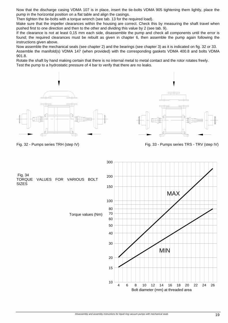
Now that the discharge casing VDMA 107 is in place, insert the tie-bolts VDMA 905 tightening them lightly, place the pump in the horizontal position on a flat table and align the casings. Then tighten the tie-bolts with a torque wrench (see tab. 13 for the required load). Make sure that the impeller clearances within the housing are correct. Check this by measuring the shaft travel when pushed first to one direction and then to the other and dividing this value by 2 (see tab. 9). If the clearance is not at least 0,15 mm each side, disassemble the pump and check all components until the error is found; the required clearances must be rebuilt as given in chapter 6, then assemble the pump again following the instructions given above. Now assemble the mechanical seals (see chapter 2) and the bearings (see chapter 3) as it is indicated on fig. 32 or 33. Assemble the manifold(s) VDMA 147 (when provided) with the corresponding gaskets VDMA 400.8 and bolts VDMA 901.8. Rotate the shaft by hand making certain that there is no internal metal to metal contact and the rotor rotates freely. Test the pump to a hydrostatic pressure of 4 bar to verify that there are no leaks.
Fig. 32 - Pumps series TRH (step IV)
Fig. 33 - Pumps series TRS - TRV (step IV)
Fig. 34
TORQUE VALUES FOR VARIOUS BOLT SIZES
Torque values (Nm)
MIN20
104
15
106 8 12 14
30
40
50
60
7080
200
100
150
300
201816 22 24 26
MAX
Bolt diameter (mm) at threaded area
Disassembly and assembly instructions for liquid ring vacuum pumps with mechanical seals 20
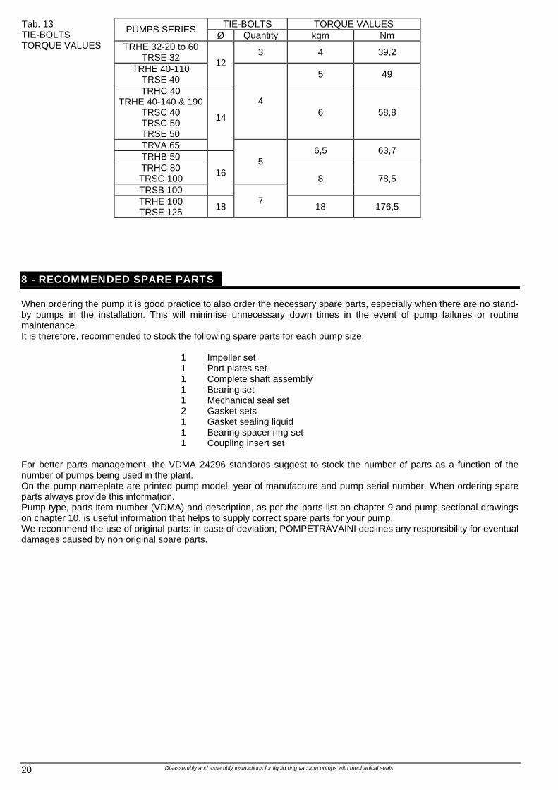
TIE-BOLTS TORQUE VALUES PUMPS SERIES Ø Quantity kgm Nm
TRHE 32-20 to 60 TRSE 32 3 4 39,2
TRHE 40-110 TRSE 40
12 5 49
TRHC 40 TRHE 40-140 & 190
TRSC 40 TRSC 50 TRSE 50
4 6 58,8
TRVA 65
14
TRHB 50 6,5 63,7
TRHC 80 TRSC 100
5
TRSB 100
16 8 78,5
Tab. 13 TIE-BOLTS TORQUE VALUES
TRHE 100 TRSE 125 18
7 18 176,5
8 - RECOMMENDED SPARE PARTS When ordering the pump it is good practice to also order the necessary spare parts, especially when there are no stand-by pumps in the installation. This will minimise unnecessary down times in the event of pump failures or routine maintenance. It is therefore, recommended to stock the following spare parts for each pump size:
1 Impeller set 1 Port plates set 1 Complete shaft assembly 1 Bearing set 1 Mechanical seal set 2 Gasket sets 1 Gasket sealing liquid 1 Bearing spacer ring set 1 Coupling insert set
For better parts management, the VDMA 24296 standards suggest to stock the number of parts as a function of the number of pumps being used in the plant. On the pump nameplate are printed pump model, year of manufacture and pump serial number. When ordering spare parts always provide this information. Pump type, parts item number (VDMA) and description, as per the parts list on chapter 9 and pump sectional drawings on chapter 10, is useful information that helps to supply correct spare parts for your pump. We recommend the use of original parts: in case of deviation, POMPETRAVAINI declines any responsibility for eventual damages caused by non original spare parts.
Disassembly and assembly instructions for liquid ring vacuum pumps with mechanical seals 21
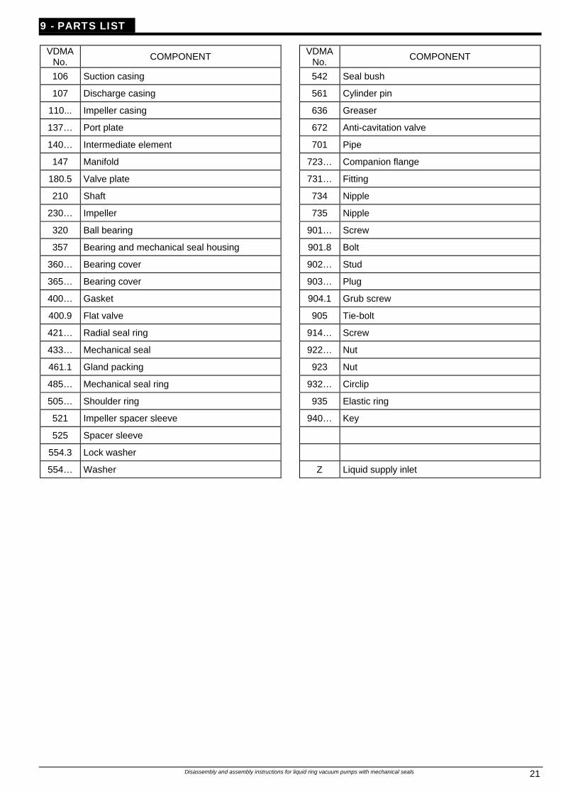
9 - PARTS LIST
VDMA No. COMPONENT VDMA
No. COMPONENT
106 Suction casing 542 Seal bush
107 Discharge casing 561 Cylinder pin
110... Impeller casing 636 Greaser
137… Port plate 672 Anti-cavitation valve
140… Intermediate element 701 Pipe
147 Manifold 723… Companion flange
180.5 Valve plate 731… Fitting
210 Shaft 734 Nipple
230… Impeller 735 Nipple
320 Ball bearing 901… Screw
357 Bearing and mechanical seal housing 901.8 Bolt
360… Bearing cover 902… Stud
365… Bearing cover 903… Plug
400… Gasket 904.1 Grub screw
400.9 Flat valve 905 Tie-bolt
421… Radial seal ring 914… Screw
433… Mechanical seal 922… Nut
461.1 Gland packing 923 Nut
485… Mechanical seal ring 932… Circlip
505… Shoulder ring 935 Elastic ring
521 Impeller spacer sleeve 940… Key
525 Spacer sleeve
554.3 Lock washer
554… Washer Z Liquid supply inlet
Disassembly and assembly instructions for liquid ring vacuum pumps with mechanical seals 22
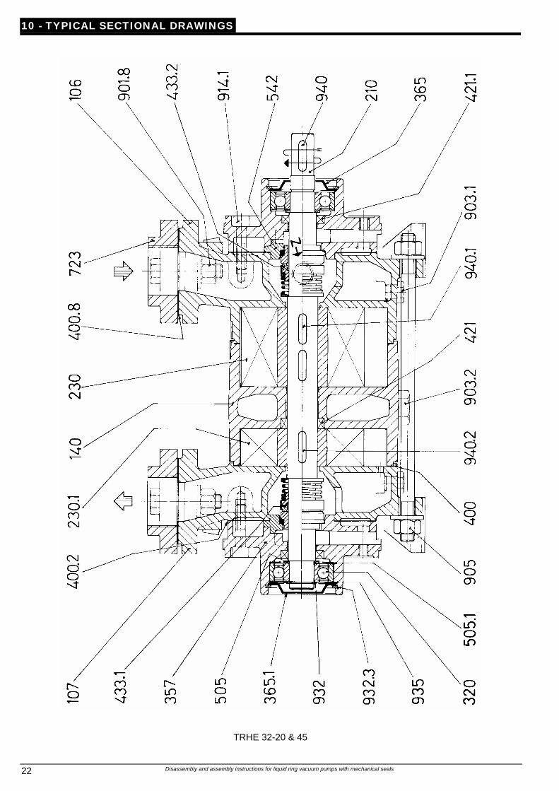
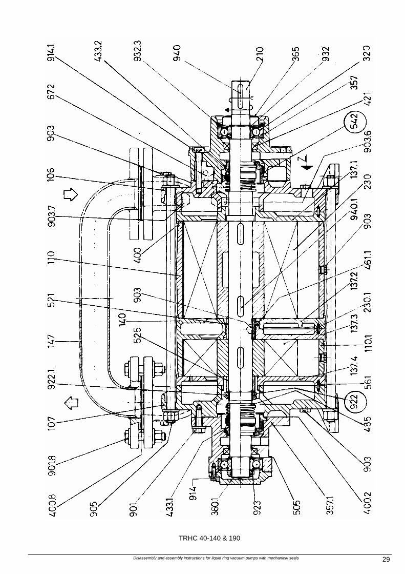
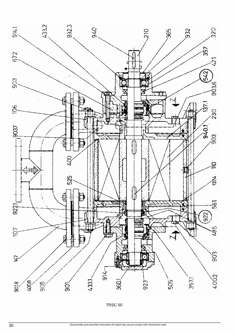
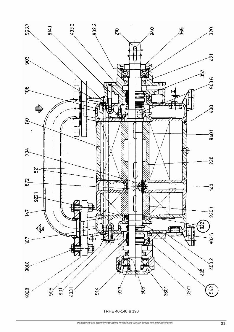
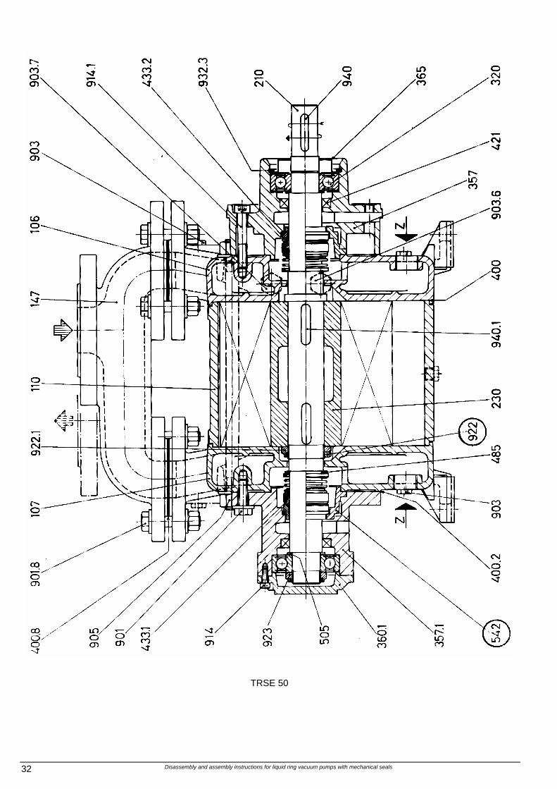
10 - TYPICAL SECTIONAL DRAWINGS
TRHE 32-20 & 45
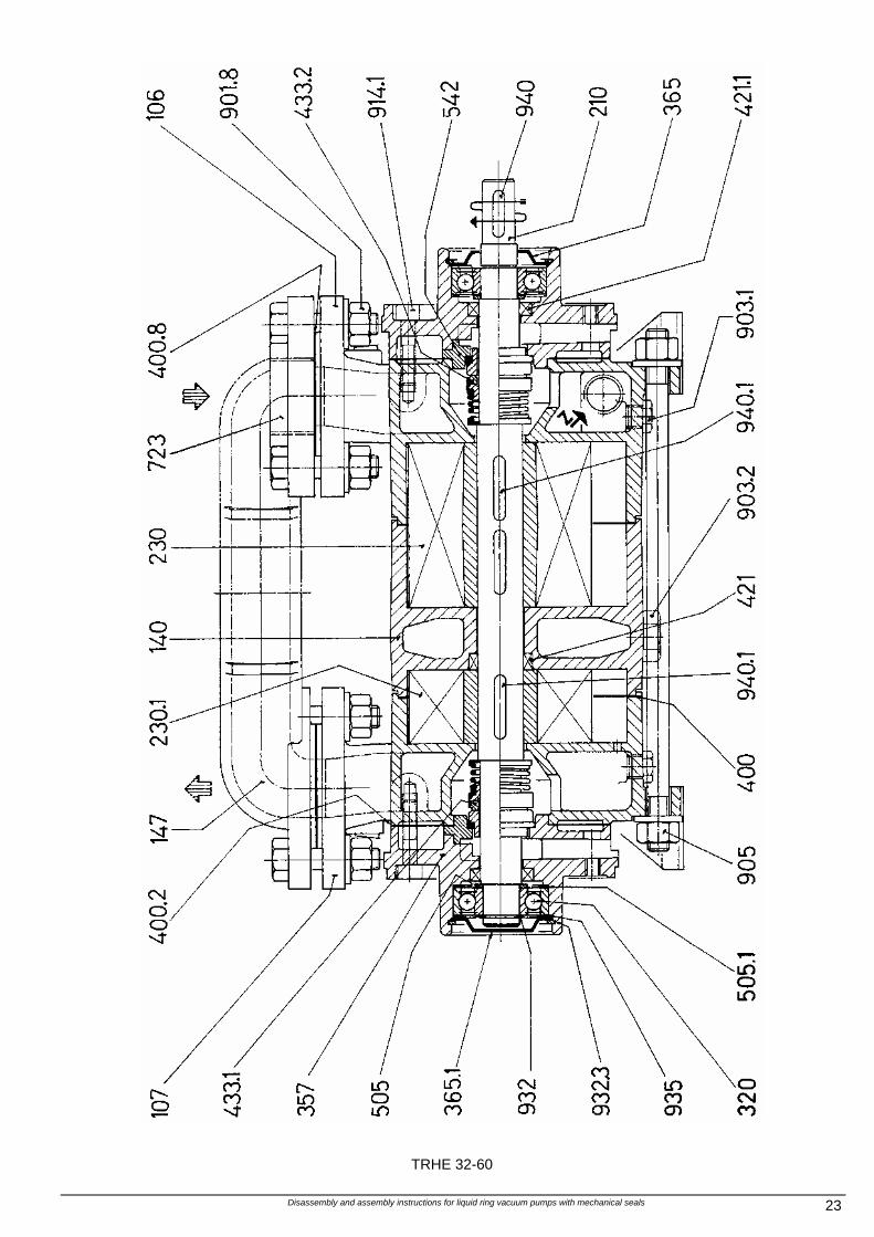
Disassembly and assembly instructions for liquid ring vacuum pumps with mechanical seals 23
TRHE 32-60
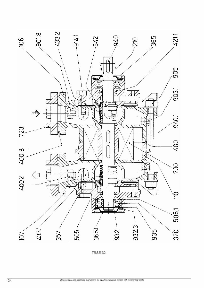
Disassembly and assembly instructions for liquid ring vacuum pumps with mechanical seals 24
TRSE 32
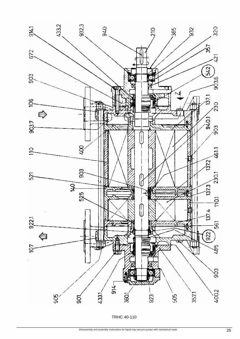
Disassembly and assembly instructions for liquid ring vacuum pumps with mechanical seals 25
TRHC 40-110
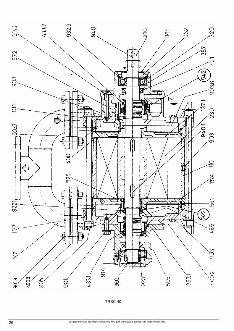
Disassembly and assembly instructions for liquid ring vacuum pumps with mechanical seals 26
TRSC 40
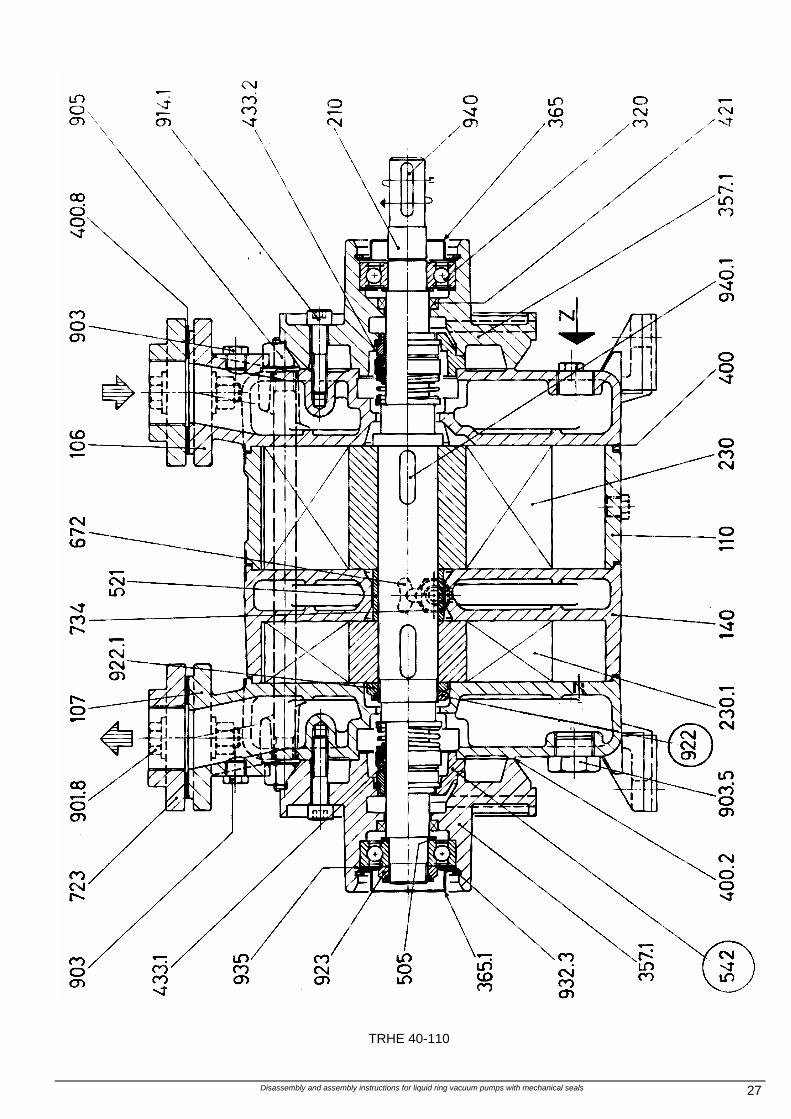
Disassembly and assembly instructions for liquid ring vacuum pumps with mechanical seals 27
TRHE 40-110
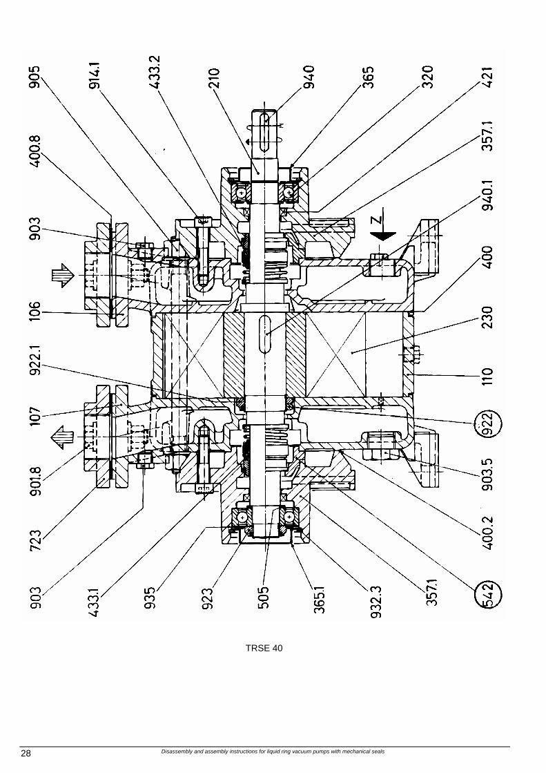
Disassembly and assembly instructions for liquid ring vacuum pumps with mechanical seals 28
TRSE 40
Disassembly and assembly instructions for liquid ring vacuum pumps with mechanical seals 29
TRHC 40-140 & 190
Disassembly and assembly instructions for liquid ring vacuum pumps with mechanical seals 30
TRSC 50
Disassembly and assembly instructions for liquid ring vacuum pumps with mechanical seals 31
TRHE 40-140 & 190
Disassembly and assembly instructions for liquid ring vacuum pumps with mechanical seals 32
TRSE 50
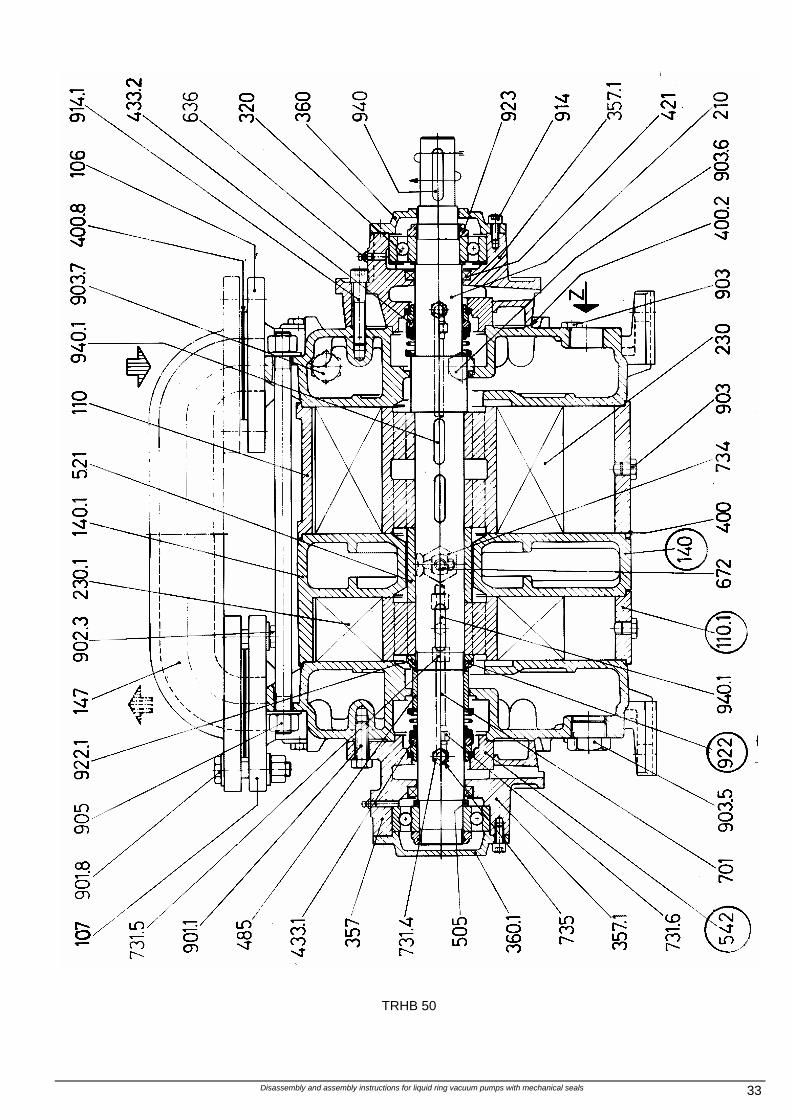
Disassembly and assembly instructions for liquid ring vacuum pumps with mechanical seals 33
TRHB 50
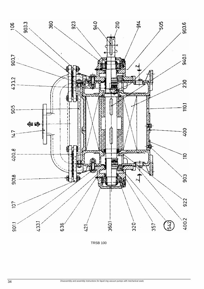
Disassembly and assembly instructions for liquid ring vacuum pumps with mechanical seals 34
TRSB 100
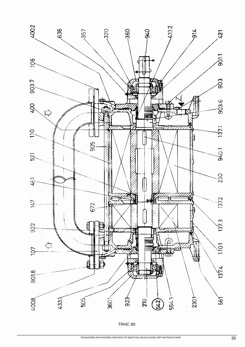
Disassembly and assembly instructions for liquid ring vacuum pumps with mechanical seals 35
TRHC 80
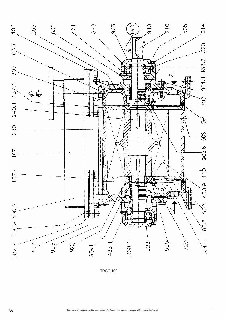
Disassembly and assembly instructions for liquid ring vacuum pumps with mechanical seals 36
TRSC 100
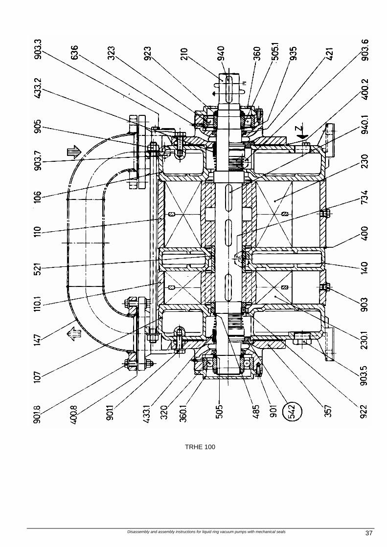
Disassembly and assembly instructions for liquid ring vacuum pumps with mechanical seals 37
TRHE 100
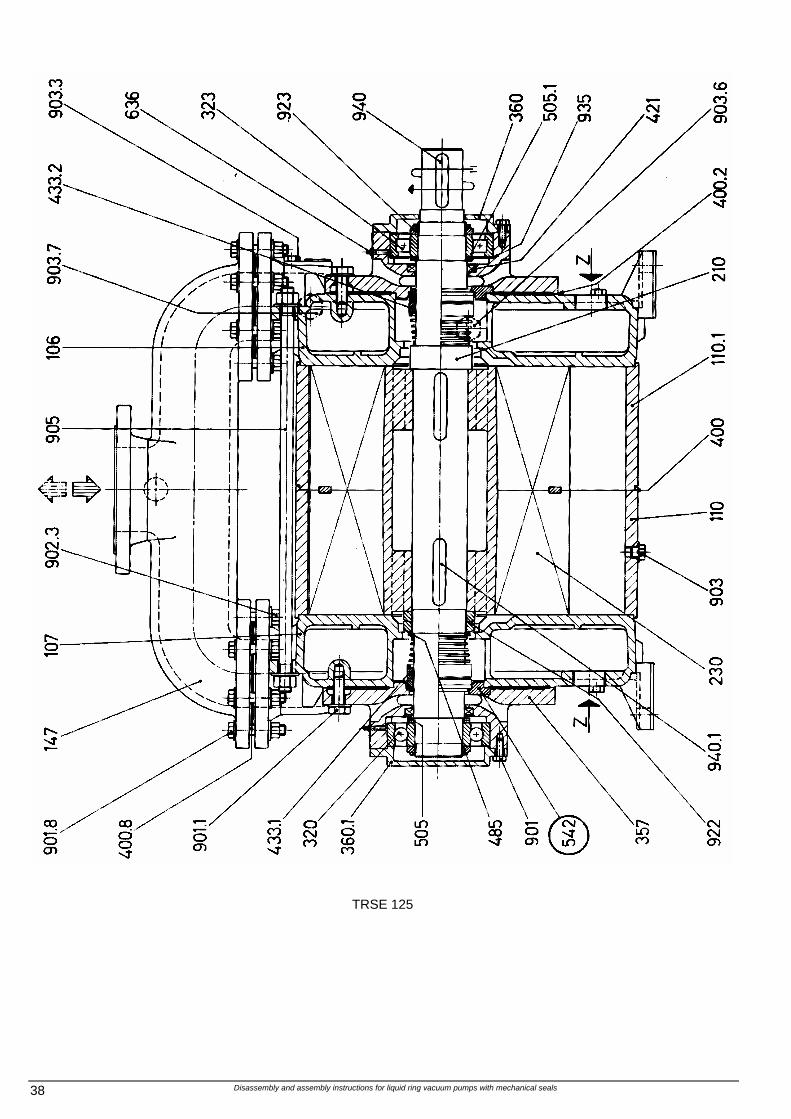
Disassembly and assembly instructions for liquid ring vacuum pumps with mechanical seals 38
TRSE 125
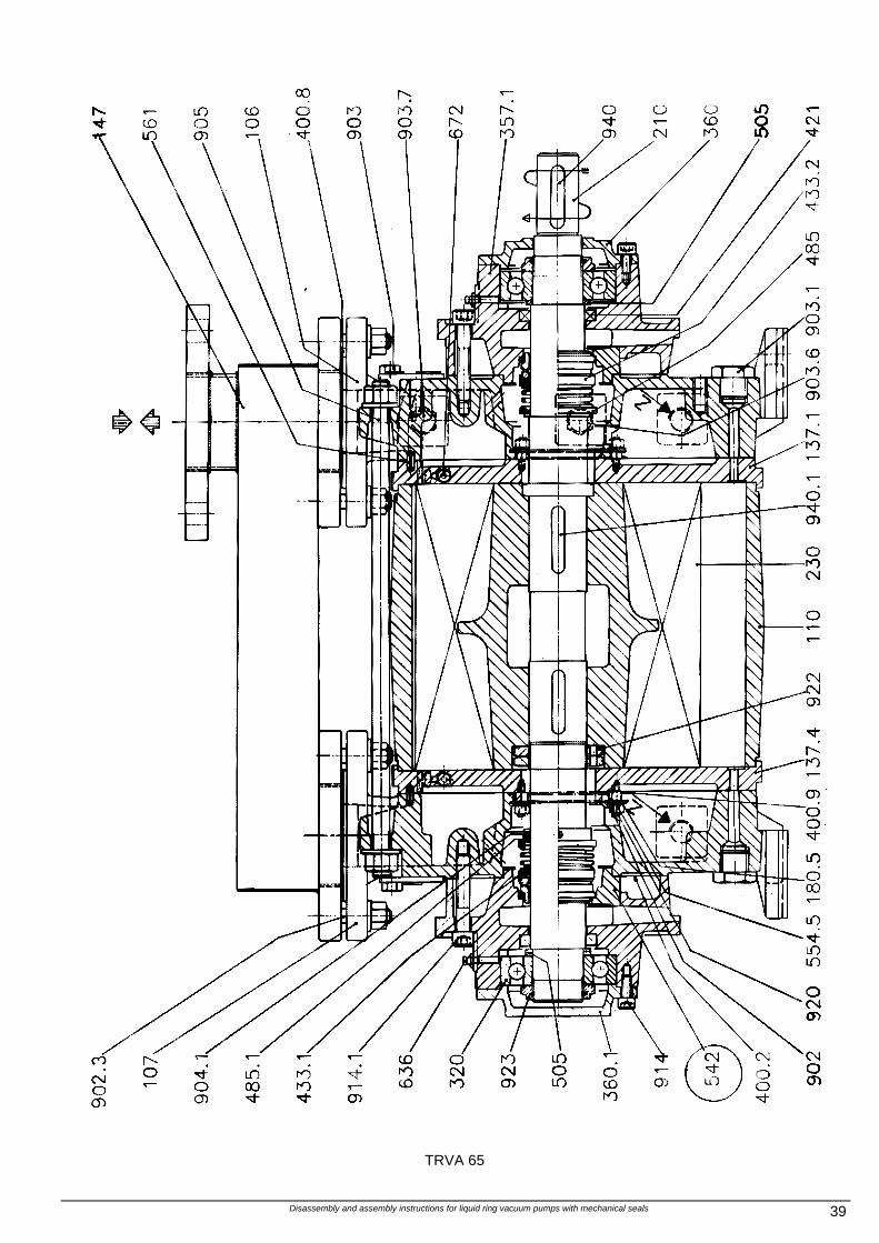
Disassembly and assembly instructions for liquid ring vacuum pumps with mechanical seals 39
TRVA 65
Disassembly and assembly instructions for liquid ring vacuum pumps with mechanical seals 40
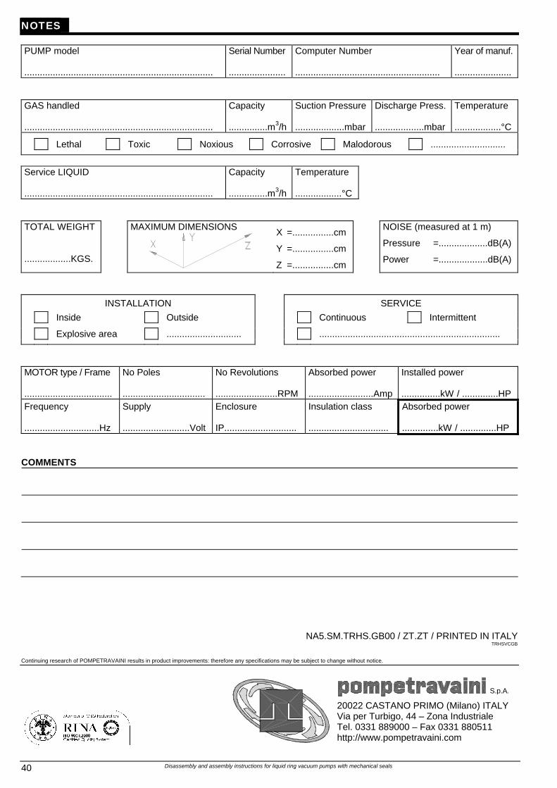
NOTES PUMP model .........................................................................
Serial Number ......................
Computer Number ........................................................
Year of manuf. ......................
GAS handled .........................................................................
Capacity ...............m3/h
Suction Pressure ...................mbar
Discharge Press. ...................mbar
Temperature ..................°C
Lethal Toxic Noxious Corrosive Malodorous .............................
Service LIQUID .........................................................................
Capacity ...............m3/h
Temperature ..................°C
TOTAL WEIGHT ..................KGS.
MAXIMUM DIMENSIONS
X =................cm
Y =................cm
Z =................cm
NOISE (measured at 1 m)
Pressure =...................dB(A)
Power =...................dB(A)
INSTALLATION SERVICE
Inside Outside Continuous Intermittent
Explosive area ............................. ......................................................................
MOTOR type / Frame ..................................
No Poles ................................
No Revolutions ........................RPM
Absorbed power .........................Amp
Installed power ...............kW / ..............HP
Frequency .............................Hz
Supply ..........................Volt
Enclosure IP............................
Insulation class ...............................
Absorbed power ..............kW / ..............HP
COMMENTS
NA5.SM.TRHS.GB00 / ZT.ZT / PRINTED IN ITALY TRHSVCGB
Continuing research of POMPETRAVAINI results in product improvements: therefore any specifications may be subject to change without notice.
S.p.A.
20022 CASTANO PRIMO (Milano) ITALY Via per Turbigo, 44 – Zona Industriale Tel. 0331 889000 – Fax 0331 880511 http://www.pompetravaini.com