dirt boss™ towable backhoe safety & operating instructions · dr® dirt boss™ towable...
TRANSCRIPT

DR® DIRT BOSS™ TOWABLE BACKHOE
SAFETY & OPERATING INSTRUCTIONS
READ AND UNDERSTAND THIS MANUAL AND ALL INSTRUCTIONS BEFORE OPERATING THIS DR BACKHOE.
Serial No.
Order No.
ii DR® DIRT BOSS™ TOWABLE BACKHOE
Congratulations on your purchase of a new DR DIRT BOSS TOWABLE BACKHOE! We have done our utmost to ensure that your DR DIRT BOSS TOWABLE BACKHOE will be one of the most trouble-free and satisfying pieces of equipment you have ever owned. Please let us know of any questions you may have. We want to answer them as quickly as possible. When you do call, please have your order number handy. For technical assistance, please contact us at www.DRpower.com call Toll-Free 1-800-DR-OWNER (376-9637) and one of our Technical Support Representatives will be happy to help you. We also hope to hear from you on how much you like your new helper. In addition, please tell your friends about your new DR DIRT BOSS TOWABLE BACKHOE! Having DR Owners spread the word about our products and our way of doing business is the best advertising we can have, and the best way to help us provide even better service in the years to come. Thanks once again!
for all of us at DR Power Equipment
Sales Manager COPYRIGHT ©2008 Country Home Products, Inc. All rights reserved.
DR® Power Equipment A division of Country Home Products® 127 Meigs Road Vergennes, VT 05491 Toll-free phone: 1-800-DR-OWNER (376-9637) Fax: 1-802-877-1213 Web site: www.DRpower.com

CONTACT US AT www.DRpower.com or CALL TOLL FREE 1-800-DR-OWNER iii
Table of Contents
CHAPTER 1 ..........................................................................................................................................1 INTRODUCING THE DR DIRT BOSS TOWABLE BACKHOE.....................................................1 Conventions used in this manual .................................................................................................1 Specifications ................................................................................................................................2 Serial Number ...............................................................................................................................3 Order Number...............................................................................................................................3
CHAPTER 2 ..........................................................................................................................................5 GENERAL SAFETY RULES ............................................................................................................5 Labels.............................................................................................................................................5 Protecting Yourself and Those Around You.................................................................................7 Safety for Children and Pets..........................................................................................................7 Safety with Gasoline - Powered Machines ...................................................................................8 Hydraulic Safety.............................................................................................................................9 Safety When Digging Near Utilities ..............................................................................................9 Towing ........................................................................................................................................10 General Safety..............................................................................................................................11 A Note to All Users......................................................................................................................13 Additional Information and Potential Changes .........................................................................13
CHAPTER 3 ........................................................................................................................................15 SETTING UP YOUR DR DIRT BOSS TOWABLE BACKHOE.....................................................15 DR Dirt Boss Towable Backhoe Controls and Features.............................................................15 Adding Oil and Gasoline.............................................................................................................16 Adding Hydraulic Fluid ...............................................................................................................17 Check the Tire Pressure ..............................................................................................................18
CHAPTER 4 ........................................................................................................................................19 OPERATING YOUR DR DIRT BOSS TOWABLE BACKHOE .....................................................19 Control Levers .............................................................................................................................19 Starting the Engine......................................................................................................................19 Stopping the Engine....................................................................................................................20 Stabilizing the Backhoe for Digging ...........................................................................................20 Digging with the Backhoe ...........................................................................................................23 Preparing the Backhoe for Towing .............................................................................................24 Towing the Backhoe ....................................................................................................................27 Hitch Coupler Adjustment Check...............................................................................................29 Hitch Coupler Adjustment..........................................................................................................29
CHAPTER 5 ........................................................................................................................................31 MAINTAINING THE DR DIRT BOSS TOWABLE BACKHOE....................................................31 Regular Maintenance Checklist ..................................................................................................31 Greasing the Backhoe .................................................................................................................32 End of Season and Storage.........................................................................................................33
CHAPTER 6 ........................................................................................................................................35 TROUBLESHOOTING ................................................................................................................35 Troubleshooting Table ................................................................................................................35

iv DR® DIRT BOSS™ TOWABLE BACKHOE
CHAPTER 7 ........................................................................................................................................37 DR DIRT BOSS TOWABLE BACKHOE ACCESSORIES .............................................................37 Installing a Bucket or Digging Tooth..........................................................................................37
CHAPTER 8 ........................................................................................................................................40 PARTS LIST AND SCHEMATIC DIAGRAMS..............................................................................40 Parts List - LINKAGE, CROWD ARM AND BOOM ASSEMBLY................................................40 Schematic – LINKAGE, CROWD ARM AND BOOM ASSEMBLY .............................................41 Parts List – SWIVEL, MAIN BOX AND STABILIZER ASSEMBLY..............................................42 Schematic – SWIVEL, MAIN BOX AND STABILIZER ASSEMBLY ............................................43 Parts List – HANDLE GUARD, VALVE MOUNT AND PANELS ASSEMBLY............................44 Schematic – HANDLE GUARD, VALVE MOUNT AND PANELS ASSEMBLY ..........................45 Parts List – CYLINDERS, PINS AND FITTINGS ASSEMBLY ....................................................46 Schematic – CYLINDERS, PINS AND FITTINGS ASSEMBLY...................................................47 Parts List – HYDRAULIC HOSES AND CYLINDERS ASSEMBLY .............................................48 Schematic – HYDRAULIC HOSES AND CYLINDERS ASSEMBLY ...........................................49 Parts List – VALVE AND FITTINGS ASSEMBLY ........................................................................50 Schematic – VALVES AND FITTINGS ASSEMBLY ....................................................................51 Parts List – HOSE CONNECTION DETAIL ...............................................................................52 Schematic – HOSE CONNECTION DETAIL..............................................................................53 Parts List – BUCKET AND TEETH ASSEMBLY ..........................................................................54 Schematic – BUCKET AND TEETH ASSEMBLY ........................................................................54 Parts List – TONGUE AND AXLE ASSEMBLY ...........................................................................56 Schematic – TONGUE AND AXLE ASSEMBLY .........................................................................57 Parts List – ENGINE AND PUMP ASSEMBLY...........................................................................58 Schematic – ENGINE AND PUMP ASSEMBLY .........................................................................59 Notes ...........................................................................................................................................61 Daily Checklist for the DR DIRT BOSS TOWABLE BACKHOE..................................................64
CONTACT US AT www.DRpower.com or CALL TOLL FREE 1-800-DR-OWNER 1
CHAPTER 1
INTRODUCING THE DR DIRT BOSS TOWABLE BACKHOE
This manual will help you set up and safely operate your new DR DIRT BOSS TOWABLE BACKHOE. Careful adherence to the safety and operating instructions in this manual will ensure many years of productive use.
Please let us know of any questions you may have. We want to answer them as quickly as possible. When you do call, please have your order number handy. For technical assistance, please contact us at www.DRpower.com or call Toll-Free 1-800-DR-OWNER (376-9637) and one of our Technical Support Representatives will be happy to help you.
Conventions used in this manual
Tip: This is a helpful hint to guide you in getting the most out of your BACKHOE.
Tools Needed: This indicates you will need a special tool to perform a maintenance function on your Backhoe. NOTE: This information may be helpful to you.
If you are ever unsure about an action you are about to take, don’t do it. Contact us at www.DRpower.com or call DR Power Equipments’ toll-free support at 1-800-DR-OWNER (376-9637) for help or information.
THIS INDICATES A HAZARDOUS SITUATION, WHICH, IF NOT FOLLOWED, WILL RESULT IN DEATH OR SERIOUS INJURY.
THIS INDICATES A HAZARDOUS SITUATION, WHICH, IF NOT AVOIDED, COULD RESULT IN DEATH OR SERIOUS INJURY.
THIS INDICATES A HAZARDOUS SITUATION, WHICH, IF NOT AVOIDED, COULD RESULT IN MINOR OR MODERATE INJURY.
THIS INFORMATION IS IMPORTANT IN THE PROPER USE OF YOUR MACHINE. FAILURE TO FOLLOW THIS INSTRUCTION COULD RESULT IN DAMAGE TO YOUR MACHINE OR PROPERTY.
2 DR® DIRT BOSS™ TOWABLE BACKHOE
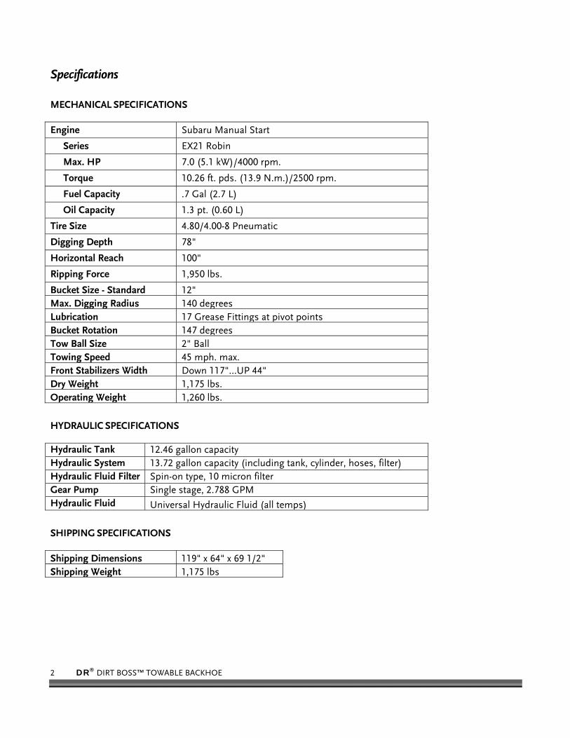
Specifications
MECHANICAL SPECIFICATIONS
Engine Subaru Manual Start
Series EX21 Robin
Max. HP 7.0 (5.1 kW)/4000 rpm.
Torque 10.26 ft. pds. (13.9 N.m.)/2500 rpm.
Fuel Capacity .7 Gal (2.7 L)
Oil Capacity 1.3 pt. (0.60 L)
Tire Size 4.80/4.00-8 Pneumatic
Digging Depth 78"
Horizontal Reach 100"
Ripping Force 1,950 lbs.
Bucket Size - Standard 12" Max. Digging Radius 140 degrees Lubrication 17 Grease Fittings at pivot points Bucket Rotation 147 degrees Tow Ball Size 2" Ball Towing Speed 45 mph. max. Front Stabilizers Width Down 117"…UP 44" Dry Weight 1,175 lbs. Operating Weight 1,260 lbs.
HYDRAULIC SPECIFICATIONS
Hydraulic Tank 12.46 gallon capacity Hydraulic System 13.72 gallon capacity (including tank, cylinder, hoses, filter) Hydraulic Fluid Filter Spin-on type, 10 micron filter Gear Pump Single stage, 2.788 GPM Hydraulic Fluid Universal Hydraulic Fluid (all temps)
SHIPPING SPECIFICATIONS
Shipping Dimensions 119" x 64" x 69 1/2" Shipping Weight 1,175 lbs

CONTACT US AT www.DRpower.com or CALL TOLL FREE 1-800-DR-OWNER 3
Serial Number
A Serial Number is used to identify your machine. The number is located on the serial number label on your machine. For your convenience and ready reference, enter the Identification number in the space provided on the front cover of this manual.
Order Number
An Order Number is used to check and maintain your order history. The number is located on the upper left portion of your packing slip. For your convenience and ready reference, enter the order number in the space provided on the front cover of this manual.

4 DR® DIRT BOSS™ TOWABLE BACKHOE
CONTACT US AT www.DRpower.com or CALL TOLL FREE 1-800-DR-OWNER 5
CHAPTER 2
GENERAL SAFETY RULES
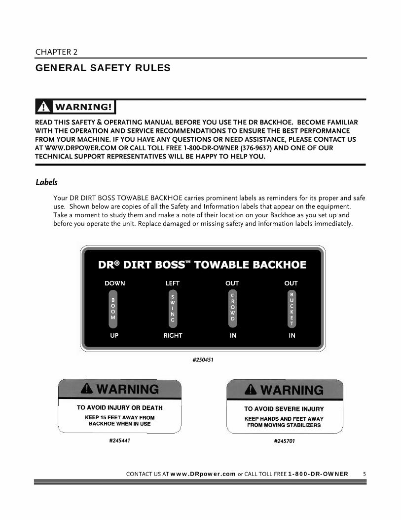
Labels
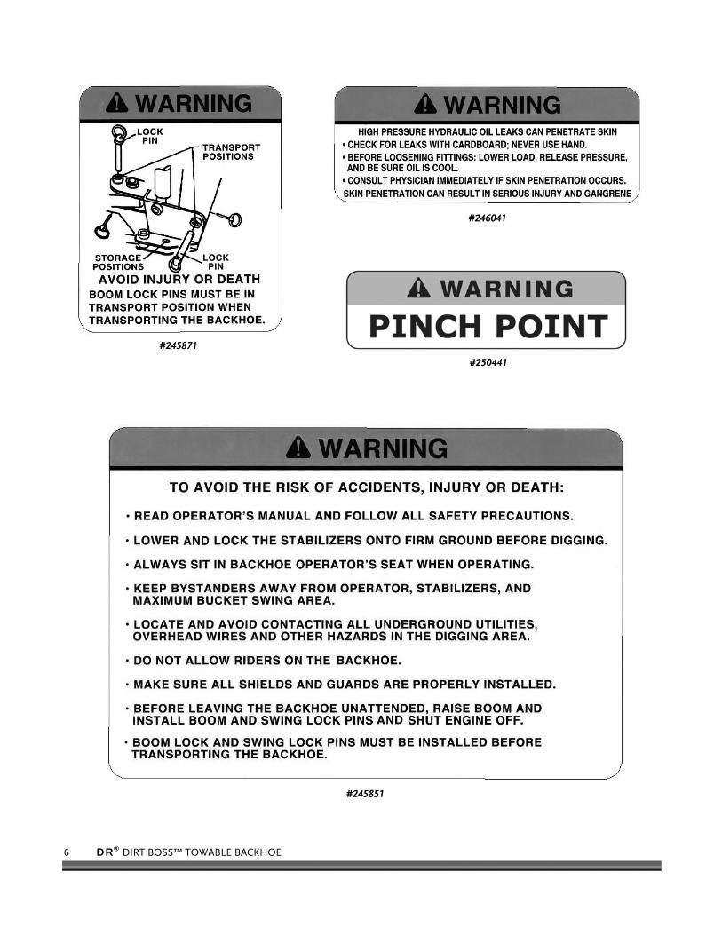
Your DR DIRT BOSS TOWABLE BACKHOE carries prominent labels as reminders for its proper and safe use. Shown below are copies of all the Safety and Information labels that appear on the equipment. Take a moment to study them and make a note of their location on your Backhoe as you set up and before you operate the unit. Replace damaged or missing safety and information labels immediately.
#250451
READ THIS SAFETY & OPERATING MANUAL BEFORE YOU USE THE DR BACKHOE. BECOME FAMILIAR WITH THE OPERATION AND SERVICE RECOMMENDATIONS TO ENSURE THE BEST PERFORMANCE FROM YOUR MACHINE. IF YOU HAVE ANY QUESTIONS OR NEED ASSISTANCE, PLEASE CONTACT US AT WWW.DRPOWER.COM OR CALL TOLL FREE 1-800-DR-OWNER (376-9637) AND ONE OF OUR TECHNICAL SUPPORT REPRESENTATIVES WILL BE HAPPY TO HELP YOU.
#245441 #245701
6 DR® DIRT BOSS™ TOWABLE BACKHOE
#245871
#250441
#246041
#245851
CONTACT US AT www.DRpower.com or CALL TOLL FREE 1-800-DR-OWNER 7
Protecting Yourself and Those Around You
Safety for Children and Pets
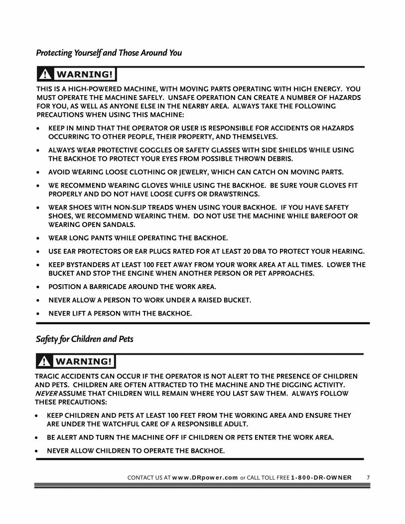
THIS IS A HIGH-POWERED MACHINE, WITH MOVING PARTS OPERATING WITH HIGH ENERGY. YOU MUST OPERATE THE MACHINE SAFELY. UNSAFE OPERATION CAN CREATE A NUMBER OF HAZARDS FOR YOU, AS WELL AS ANYONE ELSE IN THE NEARBY AREA. ALWAYS TAKE THE FOLLOWING PRECAUTIONS WHEN USING THIS MACHINE:
• KEEP IN MIND THAT THE OPERATOR OR USER IS RESPONSIBLE FOR ACCIDENTS OR HAZARDS OCCURRING TO OTHER PEOPLE, THEIR PROPERTY, AND THEMSELVES.
• ALWAYS WEAR PROTECTIVE GOGGLES OR SAFETY GLASSES WITH SIDE SHIELDS WHILE USING THE BACKHOE TO PROTECT YOUR EYES FROM POSSIBLE THROWN DEBRIS.
• AVOID WEARING LOOSE CLOTHING OR JEWELRY, WHICH CAN CATCH ON MOVING PARTS.
• WE RECOMMEND WEARING GLOVES WHILE USING THE BACKHOE. BE SURE YOUR GLOVES FIT PROPERLY AND DO NOT HAVE LOOSE CUFFS OR DRAWSTRINGS.
• WEAR SHOES WITH NON-SLIP TREADS WHEN USING YOUR BACKHOE. IF YOU HAVE SAFETY SHOES, WE RECOMMEND WEARING THEM. DO NOT USE THE MACHINE WHILE BAREFOOT OR WEARING OPEN SANDALS.
• WEAR LONG PANTS WHILE OPERATING THE BACKHOE.
• USE EAR PROTECTORS OR EAR PLUGS RATED FOR AT LEAST 20 DBA TO PROTECT YOUR HEARING.
• KEEP BYSTANDERS AT LEAST 100 FEET AWAY FROM YOUR WORK AREA AT ALL TIMES. LOWER THE BUCKET AND STOP THE ENGINE WHEN ANOTHER PERSON OR PET APPROACHES.
• POSITION A BARRICADE AROUND THE WORK AREA.
• NEVER ALLOW A PERSON TO WORK UNDER A RAISED BUCKET.
• NEVER LIFT A PERSON WITH THE BACKHOE.
TRAGIC ACCIDENTS CAN OCCUR IF THE OPERATOR IS NOT ALERT TO THE PRESENCE OF CHILDREN AND PETS. CHILDREN ARE OFTEN ATTRACTED TO THE MACHINE AND THE DIGGING ACTIVITY. NEVER ASSUME THAT CHILDREN WILL REMAIN WHERE YOU LAST SAW THEM. ALWAYS FOLLOW THESE PRECAUTIONS:
• KEEP CHILDREN AND PETS AT LEAST 100 FEET FROM THE WORKING AREA AND ENSURE THEY ARE UNDER THE WATCHFUL CARE OF A RESPONSIBLE ADULT.
• BE ALERT AND TURN THE MACHINE OFF IF CHILDREN OR PETS ENTER THE WORK AREA.
• NEVER ALLOW CHILDREN TO OPERATE THE BACKHOE.
8 DR® DIRT BOSS™ TOWABLE BACKHOE
Safety with Gasoline - Powered Machines
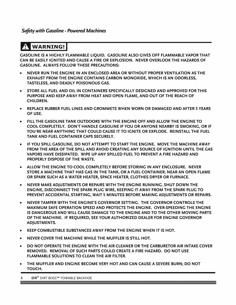
GASOLINE IS A HIGHLY FLAMMABLE LIQUID. GASOLINE ALSO GIVES OFF FLAMMABLE VAPOR THAT CAN BE EASILY IGNITED AND CAUSE A FIRE OR EXPLOSION. NEVER OVERLOOK THE HAZARDS OF GASOLINE. ALWAYS FOLLOW THESE PRECAUTIONS:
• NEVER RUN THE ENGINE IN AN ENCLOSED AREA OR WITHOUT PROPER VENTILATION AS THE EXHAUST FROM THE ENGINE CONTAINS CARBON MONOXIDE, WHICH IS AN ODORLESS, TASTELESS, AND DEADLY POISONOUS GAS.
• STORE ALL FUEL AND OIL IN CONTAINERS SPECIFICALLY DESIGNED AND APPROVED FOR THIS PURPOSE AND KEEP AWAY FROM HEAT AND OPEN FLAME, AND OUT OF THE REACH OF CHILDREN.
• REPLACE RUBBER FUEL LINES AND GROMMETS WHEN WORN OR DAMAGED AND AFTER 5 YEARS OF USE.
• FILL THE GASOLINE TANK OUTDOORS WITH THE ENGINE OFF AND ALLOW THE ENGINE TO COOL COMPLETELY. DON'T HANDLE GASOLINE IF YOU OR ANYONE NEARBY IS SMOKING, OR IF YOU'RE NEAR ANYTHING THAT COULD CAUSE IT TO IGNITE OR EXPLODE. REINSTALL THE FUEL TANK AND FUEL CONTAINER CAPS SECURELY.
• IF YOU SPILL GASOLINE, DO NOT ATTEMPT TO START THE ENGINE. MOVE THE MACHINE AWAY FROM THE AREA OF THE SPILL AND AVOID CREATING ANY SOURCE OF IGNITION UNTIL THE GAS VAPORS HAVE DISSIPATED. WIPE UP ANY SPILLED FUEL TO PREVENT A FIRE HAZARD AND PROPERLY DISPOSE OF THE WASTE.
• ALLOW THE ENGINE TO COOL COMPLETELY BEFORE STORING IN ANY ENCLOSURE. NEVER STORE A MACHINE THAT HAS GAS IN THE TANK, OR A FUEL CONTAINER, NEAR AN OPEN FLAME OR SPARK SUCH AS A WATER HEATER, SPACE HEATER, CLOTHES DRYER OR FURNACE.
• NEVER MAKE ADJUSTMENTS OR REPAIRS WITH THE ENGINE RUNNING. SHUT DOWN THE ENGINE, DISCONNECT THE SPARK PLUG WIRE, KEEPING IT AWAY FROM THE SPARK PLUG TO PREVENT ACCIDENTAL STARTING, WAIT 5 MINUTES BEFORE MAKING ADJUSTMENTS OR REPAIRS.
• NEVER TAMPER WITH THE ENGINE’S GOVERNOR SETTING. THE GOVERNOR CONTROLS THE MAXIMUM SAFE OPERATION SPEED AND PROTECTS THE ENGINE. OVER-SPEEDING THE ENGINE IS DANGEROUS AND WILL CAUSE DAMAGE TO THE ENGINE AND TO THE OTHER MOVING PARTS OF THE MACHINE. IF REQUIRED, SEE YOUR AUTHORIZED DEALER FOR ENGINE GOVERNOR ADJUSTMENTS.
• KEEP COMBUSTIBLE SUBSTANCES AWAY FROM THE ENGINE WHEN IT IS HOT.
• NEVER COVER THE MACHINE WHILE THE MUFFLER IS STILL HOT.
• DO NOT OPERATE THE ENGINE WITH THE AIR CLEANER OR THE CARBURETOR AIR INTAKE COVER REMOVED. REMOVAL OF SUCH PARTS COULD CREATE A FIRE HAZARD. DO NOT USE FLAMMABLE SOLUTIONS TO CLEAN THE AIR FILTER.
• THE MUFFLER AND ENGINE BECOME VERY HOT AND CAN CAUSE A SEVERE BURN; DO NOT TOUCH.

CONTACT US AT www.DRpower.com or CALL TOLL FREE 1-800-DR-OWNER 9
Hydraulic Safety
Safety When Digging Near Utilities
HIGH FLUID PRESSURES ARE DEVELOPED IN HYDRAULIC MACHINES. PRESSURIZED HYDRAULIC FLUID ESCAPING THROUGH A PIN HOLE OPENING CAN PUNCTURE SKIN AND CAUSE SEVERE BLOOD POISONING. THEREFORE, THE FOLLOWING INSTRUCTIONS SHOULD BE HEEDED AT ALL TIMES.
• DO NOT OPERATE THE UNIT WITH FRAYED, KINKED, CRACKED OR DAMAGED HOSES, FITTINGS, OR TUBING. STOP THE ENGINE, WAIT 5 MINUTES AND RELIEVE HYDRAULIC SYSTEM PRESSURE BEFORE CHANGING OR ADJUSTING FITTINGS, HOSES, TUBING, OR OTHER SYSTEM COMPONENTS.
• DO NOT CHANGE ANY BACKHOE NEEDLE VALVE SETTINGS. THEY ARE SET AT THE FACTORY FOR BEST BACKHOE PERFORMANCE AND SAFETY.
• DO NOT CHECK FOR LEAKS WITH YOUR HAND. LEAKS CAN BE LOCATED BY PASSING CARDBOARD OR WOOD OVER THE SUSPECTED AREA: LOOK FOR DISCOLORATION. IF INJURED BY ESCAPING FLUID, SEE A DOCTOR AT ONCE. SERIOUS INFECTION OR REACTION CAN DEVELOP IF PROPER MEDICAL TREATMENT IS NOT ADMINISTERED IMMEDIATELY.
• ALWAYS WEAR SAFETY GLASSES TO PROTECT YOUR EYES FROM HYDRAULIC FLUID.
CALL 811 BEFORE YOU BEGIN ANY DIGGING PROJECT. A NEW, FEDERALLY-MANDATED NATIONAL "CALL BEFORE YOU DIG" NUMBER, 811 WAS CREATED TO HELP PROTECT YOU FROM UNINTENTIONALLY HITTING UNDERGROUND UTILITIES WHILE WORKING ON DIGGING PROJECTS. EVERY DIGGING JOB REQUIRES A CALL. IF YOU HIT AN UNDERGROUND UTILITY LINE WHILE DIGGING, YOU CAN HARM YOURSELF OR THOSE AROUND YOU, DISRUPT SERVICE AND POTENTIALLY BE RESPONSIBLE FOR FINES AND REPAIR COSTS.
• THERE MAY BE BURIED POWER, GAS, AND/OR TELEPHONE LINES IN THE WORK AREA. ELECTRIC SHOCK, DEATH, OR EXPLOSION MAY OCCUR.
• HAVE THE PROPERTY OR WORK AREA MARKED FOR BURIED LINES AND DO NOT DIG IN MARKED AREAS.
• THERE MAY ALSO BE OVERHEAD POWER LINES IN THE WORK AREA. ELECTRIC SHOCK OR DEATH MAY OCCUR IF A POWER LINE IS TOUCHED BY THE BACKHOE.
• SURVEY AND MARK THE AREA WHERE THERE ARE OVERHEAD POWER LINES AND DIG WITH CAUTION UNDER POWER LINES TO ENSURE THAT YOU DO NOT TOUCH THEM WITH THE BACKHOE.
10 DR® DIRT BOSS™ TOWABLE BACKHOE
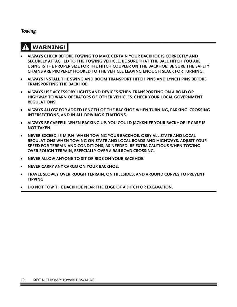
Towing
• ALWAYS CHECK BEFORE TOWING TO MAKE CERTAIN YOUR BACKHOE IS CORRECTLY AND SECURELY ATTACHED TO THE TOWING VEHICLE. BE SURE THAT THE BALL HITCH YOU ARE USING IS THE PROPER SIZE FOR THE HITCH COUPLER ON THE BACKHOE. BE SURE THE SAFETY CHAINS ARE PROPERLY HOOKED TO THE VEHICLE LEAVING ENOUGH SLACK FOR TURNING.
• ALWAYS INSTALL THE SWING AND BOOM TRANSPORT HITCH PINS AND LYNCH PINS BEFORE TRANSPORTING THE BACKHOE.
• ALWAYS USE ACCESSORY LIGHTS AND DEVICES WHEN TRANSPORTING ON A ROAD OR HIGHWAY TO WARN OPERATORS OF OTHER VEHICLES. CHECK YOUR LOCAL GOVERNMENT REGULATIONS.
• ALWAYS ALLOW FOR ADDED LENGTH OF THE BACKHOE WHEN TURNING, PARKING, CROSSING INTERSECTIONS, AND IN ALL DRIVING SITUATIONS.
• ALWAYS BE CAREFUL WHEN BACKING UP. YOU COULD JACKKNIFE YOUR BACKHOE IF CARE IS NOT TAKEN.
• NEVER EXCEED 45 M.P.H. WHEN TOWING YOUR BACKHOE. OBEY ALL STATE AND LOCAL REGULATIONS WHEN TOWING ON STATE AND LOCAL ROADS AND HIGHWAYS. ADJUST YOUR SPEED FOR TERRAIN AND CONDITIONS, AS NEEDED. BE EXTRA CAUTIOUS WHEN TOWING OVER ROUGH TERRAIN, ESPECIALLY OVER A RAILROAD CROSSING.
• NEVER ALLOW ANYONE TO SIT OR RIDE ON YOUR BACKHOE.
• NEVER CARRY ANY CARGO ON YOUR BACKHOE.
• TRAVEL SLOWLY OVER ROUGH TERRAIN, ON HILLSIDES, AND AROUND CURVES TO PREVENT TIPPING.
• DO NOT TOW THE BACKHOE NEAR THE EDGE OF A DITCH OR EXCAVATION.
CONTACT US AT www.DRpower.com or CALL TOLL FREE 1-800-DR-OWNER 11
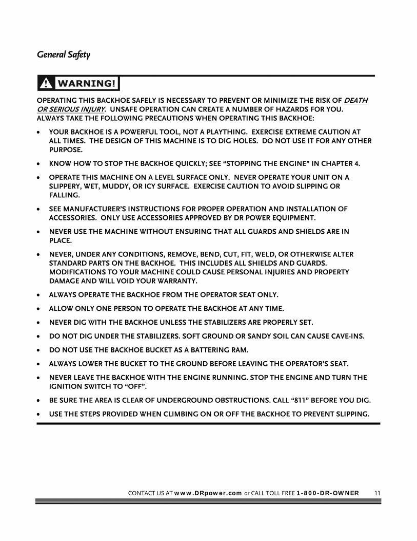
General Safety
OPERATING THIS BACKHOE SAFELY IS NECESSARY TO PREVENT OR MINIMIZE THE RISK OF DEATH OR SERIOUS INJURY. UNSAFE OPERATION CAN CREATE A NUMBER OF HAZARDS FOR YOU. ALWAYS TAKE THE FOLLOWING PRECAUTIONS WHEN OPERATING THIS BACKHOE:
• YOUR BACKHOE IS A POWERFUL TOOL, NOT A PLAYTHING. EXERCISE EXTREME CAUTION AT ALL TIMES. THE DESIGN OF THIS MACHINE IS TO DIG HOLES. DO NOT USE IT FOR ANY OTHER PURPOSE.
• KNOW HOW TO STOP THE BACKHOE QUICKLY; SEE “STOPPING THE ENGINE” IN CHAPTER 4.
• OPERATE THIS MACHINE ON A LEVEL SURFACE ONLY. NEVER OPERATE YOUR UNIT ON A SLIPPERY, WET, MUDDY, OR ICY SURFACE. EXERCISE CAUTION TO AVOID SLIPPING OR FALLING.
• SEE MANUFACTURER’S INSTRUCTIONS FOR PROPER OPERATION AND INSTALLATION OF ACCESSORIES. ONLY USE ACCESSORIES APPROVED BY DR POWER EQUIPMENT.
• NEVER USE THE MACHINE WITHOUT ENSURING THAT ALL GUARDS AND SHIELDS ARE IN PLACE.
• NEVER, UNDER ANY CONDITIONS, REMOVE, BEND, CUT, FIT, WELD, OR OTHERWISE ALTER STANDARD PARTS ON THE BACKHOE. THIS INCLUDES ALL SHIELDS AND GUARDS. MODIFICATIONS TO YOUR MACHINE COULD CAUSE PERSONAL INJURIES AND PROPERTY DAMAGE AND WILL VOID YOUR WARRANTY.
• ALWAYS OPERATE THE BACKHOE FROM THE OPERATOR SEAT ONLY.
• ALLOW ONLY ONE PERSON TO OPERATE THE BACKHOE AT ANY TIME.
• NEVER DIG WITH THE BACKHOE UNLESS THE STABILIZERS ARE PROPERLY SET.
• DO NOT DIG UNDER THE STABILIZERS. SOFT GROUND OR SANDY SOIL CAN CAUSE CAVE-INS.
• DO NOT USE THE BACKHOE BUCKET AS A BATTERING RAM.
• ALWAYS LOWER THE BUCKET TO THE GROUND BEFORE LEAVING THE OPERATOR’S SEAT.
• NEVER LEAVE THE BACKHOE WITH THE ENGINE RUNNING. STOP THE ENGINE AND TURN THE IGNITION SWITCH TO “OFF”.
• BE SURE THE AREA IS CLEAR OF UNDERGROUND OBSTRUCTIONS. CALL “811” BEFORE YOU DIG.
• USE THE STEPS PROVIDED WHEN CLIMBING ON OR OFF THE BACKHOE TO PREVENT SLIPPING.
12 DR® DIRT BOSS™ TOWABLE BACKHOE
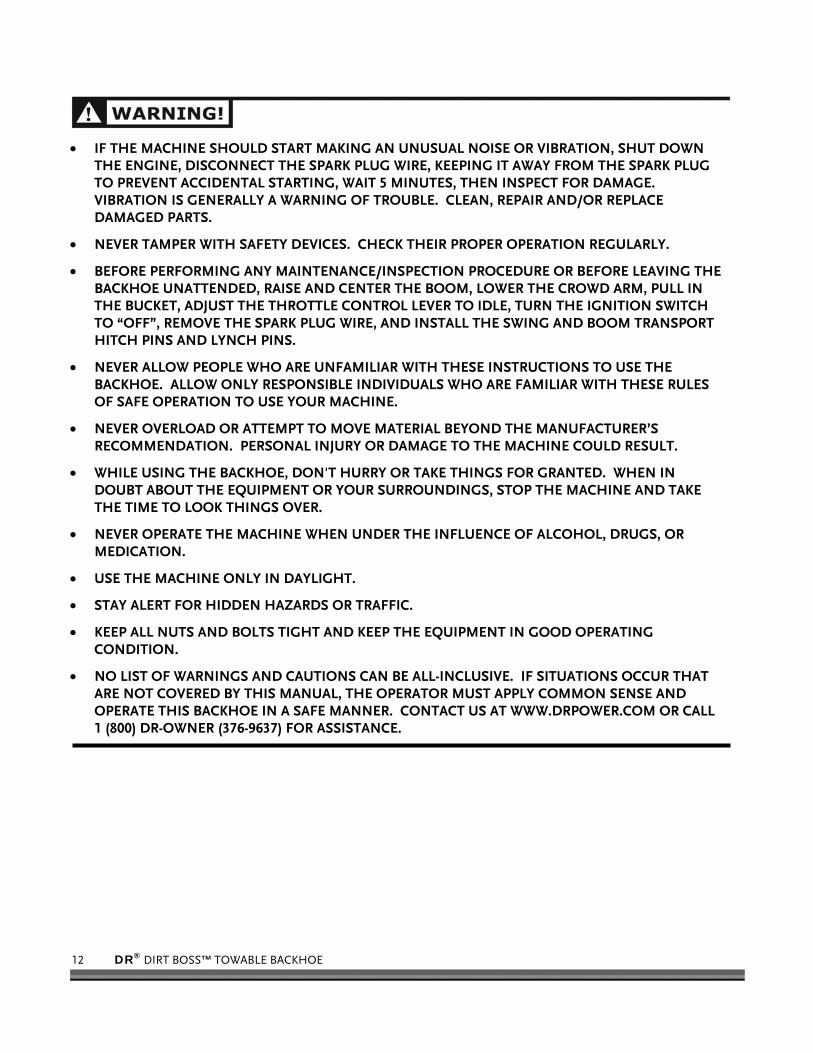
• IF THE MACHINE SHOULD START MAKING AN UNUSUAL NOISE OR VIBRATION, SHUT DOWN THE ENGINE, DISCONNECT THE SPARK PLUG WIRE, KEEPING IT AWAY FROM THE SPARK PLUG TO PREVENT ACCIDENTAL STARTING, WAIT 5 MINUTES, THEN INSPECT FOR DAMAGE. VIBRATION IS GENERALLY A WARNING OF TROUBLE. CLEAN, REPAIR AND/OR REPLACE DAMAGED PARTS.
• NEVER TAMPER WITH SAFETY DEVICES. CHECK THEIR PROPER OPERATION REGULARLY.
• BEFORE PERFORMING ANY MAINTENANCE/INSPECTION PROCEDURE OR BEFORE LEAVING THE BACKHOE UNATTENDED, RAISE AND CENTER THE BOOM, LOWER THE CROWD ARM, PULL IN THE BUCKET, ADJUST THE THROTTLE CONTROL LEVER TO IDLE, TURN THE IGNITION SWITCH TO “OFF”, REMOVE THE SPARK PLUG WIRE, AND INSTALL THE SWING AND BOOM TRANSPORT HITCH PINS AND LYNCH PINS.
• NEVER ALLOW PEOPLE WHO ARE UNFAMILIAR WITH THESE INSTRUCTIONS TO USE THE BACKHOE. ALLOW ONLY RESPONSIBLE INDIVIDUALS WHO ARE FAMILIAR WITH THESE RULES OF SAFE OPERATION TO USE YOUR MACHINE.
• NEVER OVERLOAD OR ATTEMPT TO MOVE MATERIAL BEYOND THE MANUFACTURER’S RECOMMENDATION. PERSONAL INJURY OR DAMAGE TO THE MACHINE COULD RESULT.
• WHILE USING THE BACKHOE, DON'T HURRY OR TAKE THINGS FOR GRANTED. WHEN IN DOUBT ABOUT THE EQUIPMENT OR YOUR SURROUNDINGS, STOP THE MACHINE AND TAKE THE TIME TO LOOK THINGS OVER.
• NEVER OPERATE THE MACHINE WHEN UNDER THE INFLUENCE OF ALCOHOL, DRUGS, OR MEDICATION.
• USE THE MACHINE ONLY IN DAYLIGHT.
• STAY ALERT FOR HIDDEN HAZARDS OR TRAFFIC.
• KEEP ALL NUTS AND BOLTS TIGHT AND KEEP THE EQUIPMENT IN GOOD OPERATING CONDITION.
• NO LIST OF WARNINGS AND CAUTIONS CAN BE ALL-INCLUSIVE. IF SITUATIONS OCCUR THAT ARE NOT COVERED BY THIS MANUAL, THE OPERATOR MUST APPLY COMMON SENSE AND OPERATE THIS BACKHOE IN A SAFE MANNER. CONTACT US AT WWW.DRPOWER.COM OR CALL 1 (800) DR-OWNER (376-9637) FOR ASSISTANCE.
CONTACT US AT www.DRpower.com or CALL TOLL FREE 1-800-DR-OWNER 13
A Note to All Users
Under California law, and the laws of some other states, you are not permitted to operate an internal combustion engine using hydrocarbon fuels without an engine spark arrester. This also applies to operation on US Forest Lands. All DR® DIRT BOSS™ TOWABLE BACKHOES shipped to California, New Mexico and Washington State are provided with spark arresters. Failure of the owner or operator to maintain this equipment in compliance with state regulations is a misdemeanor under California law and may be in violation of other state and/or federal regulations. Contact your State Park Association or the appropriate state organization for specific information in your area.
Additional Information and Potential Changes
DR Power Equipment reserves the right to discontinue, change, and improve its products at any time without notice or obligation to the purchaser. The descriptions and specifications contained in this manual were in effect at printing. Equipment described within this manual may be optional. Some illustrations may not be applicable to your machine.

14 DR® DIRT BOSS™ TOWABLE BACKHOE
CONTACT US AT www.DRpower.com or CALL TOLL FREE 1-800-DR-OWNER 15
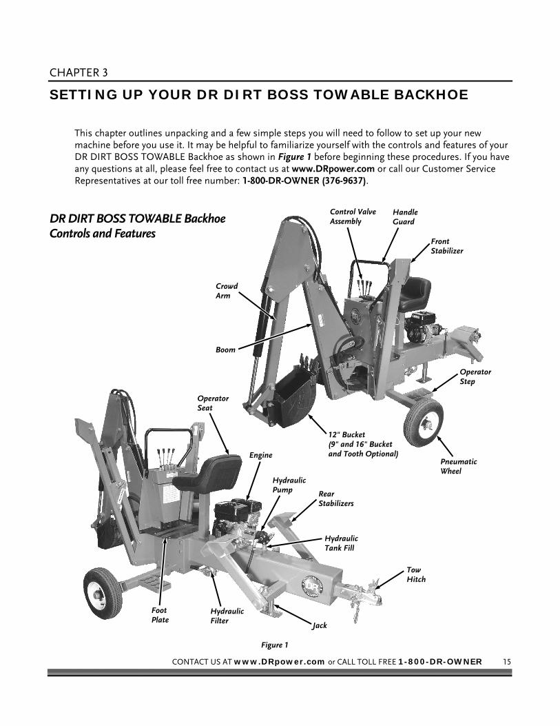
Rear Stabilizers
Control Valve Assembly
Figure 1
Boom
Handle Guard
Operator Seat
Engine
Hydraulic Pump
Front Stabilizer
Tow Hitch
Hydraulic Tank Fill
Jack
Hydraulic Filter
Operator Step
Pneumatic Wheel
12" Bucket (9" and 16" Bucket and Tooth Optional)
Foot Plate
Crowd Arm
CHAPTER 3
SETTING UP YOUR DR DIRT BOSS TOWABLE BACKHOE
This chapter outlines unpacking and a few simple steps you will need to follow to set up your new machine before you use it. It may be helpful to familiarize yourself with the controls and features of your DR DIRT BOSS TOWABLE Backhoe as shown in Figure 1 before beginning these procedures. If you have any questions at all, please feel free to contact us at www.DRpower.com or call our Customer Service Representatives at our toll free number: 1-800-DR-OWNER (376-9637).
DR DIRT BOSS TOWABLE Backhoe Controls and Features
16 DR® DIRT BOSS™ TOWABLE BACKHOE
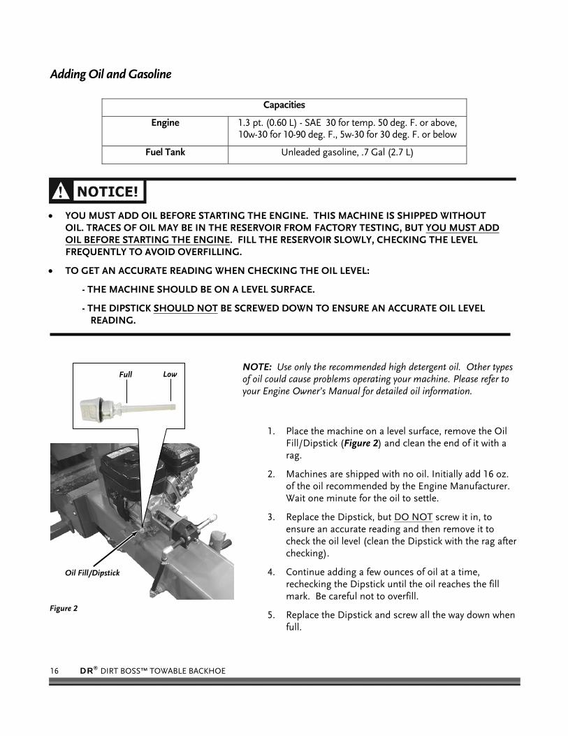
Adding Oil and Gasoline
Capacities
Engine 1.3 pt. (0.60 L) - SAE 30 for temp. 50 deg. F. or above, 10w-30 for 10-90 deg. F., 5w-30 for 30 deg. F. or below
Fuel Tank Unleaded gasoline, .7 Gal (2.7 L)
NOTE: Use only the recommended high detergent oil. Other types of oil could cause problems operating your machine. Please refer to your Engine Owner’s Manual for detailed oil information.
1. Place the machine on a level surface, remove the Oil Fill/Dipstick (Figure 2) and clean the end of it with a rag.
2. Machines are shipped with no oil. Initially add 16 oz. of the oil recommended by the Engine Manufacturer. Wait one minute for the oil to settle.
3. Replace the Dipstick, but DO NOT screw it in, to ensure an accurate reading and then remove it to check the oil level (clean the Dipstick with the rag after checking).
4. Continue adding a few ounces of oil at a time, rechecking the Dipstick until the oil reaches the fill mark. Be careful not to overfill.
5. Replace the Dipstick and screw all the way down when full.
• YOU MUST ADD OIL BEFORE STARTING THE ENGINE. THIS MACHINE IS SHIPPED WITHOUT OIL. TRACES OF OIL MAY BE IN THE RESERVOIR FROM FACTORY TESTING, BUT YOU MUST ADD OIL BEFORE STARTING THE ENGINE. FILL THE RESERVOIR SLOWLY, CHECKING THE LEVEL FREQUENTLY TO AVOID OVERFILLING.
• TO GET AN ACCURATE READING WHEN CHECKING THE OIL LEVEL:
- THE MACHINE SHOULD BE ON A LEVEL SURFACE.
- THE DIPSTICK SHOULD NOT BE SCREWED DOWN TO ENSURE AN ACCURATE OIL LEVEL READING.
Oil Fill/Dipstick
Figure 2
Full Low
CONTACT US AT www.DRpower.com or CALL TOLL FREE 1-800-DR-OWNER 17
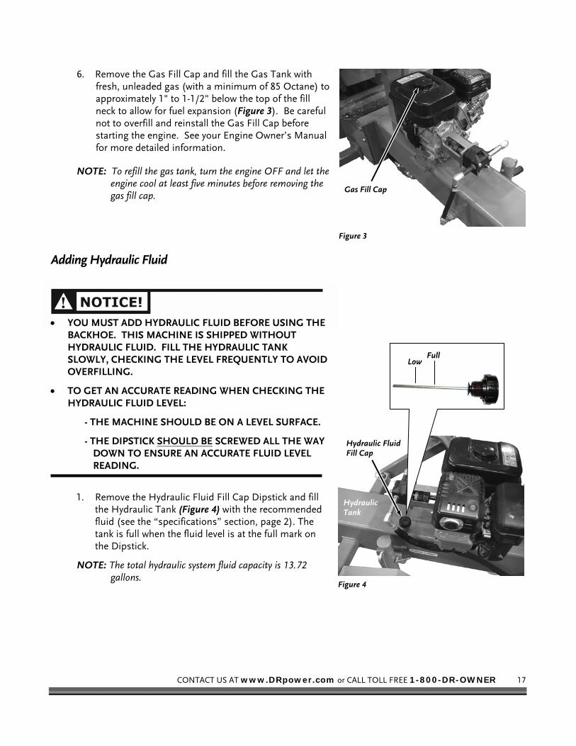
6. Remove the Gas Fill Cap and fill the Gas Tank with fresh, unleaded gas (with a minimum of 85 Octane) to approximately 1" to 1-1/2" below the top of the fill neck to allow for fuel expansion (Figure 3). Be careful not to overfill and reinstall the Gas Fill Cap before starting the engine. See your Engine Owner’s Manual for more detailed information.
NOTE: To refill the gas tank, turn the engine OFF and let the engine cool at least five minutes before removing the gas fill cap.
Adding Hydraulic Fluid
1. Remove the Hydraulic Fluid Fill Cap Dipstick and fill the Hydraulic Tank (Figure 4) with the recommended fluid (see the “specifications” section, page 2). The tank is full when the fluid level is at the full mark on the Dipstick.
NOTE: The total hydraulic system fluid capacity is 13.72 gallons.
Gas Fill Cap
Figure 3
Hydraulic Fluid Fill Cap
Figure 4
Hydraulic Tank
Full Low
• YOU MUST ADD HYDRAULIC FLUID BEFORE USING THE BACKHOE. THIS MACHINE IS SHIPPED WITHOUT HYDRAULIC FLUID. FILL THE HYDRAULIC TANK SLOWLY, CHECKING THE LEVEL FREQUENTLY TO AVOID OVERFILLING.
• TO GET AN ACCURATE READING WHEN CHECKING THE HYDRAULIC FLUID LEVEL:
- THE MACHINE SHOULD BE ON A LEVEL SURFACE.
- THE DIPSTICK SHOULD BE SCREWED ALL THE WAY DOWN TO ENSURE AN ACCURATE FLUID LEVEL READING.
18 DR® DIRT BOSS™ TOWABLE BACKHOE
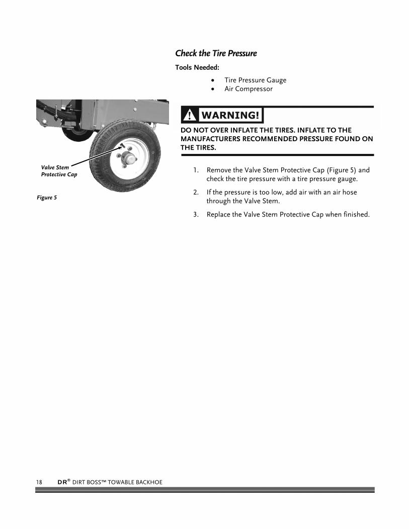
Check the Tire Pressure
Tools Needed:
• Tire Pressure Gauge • Air Compressor
1. Remove the Valve Stem Protective Cap (Figure 5) and check the tire pressure with a tire pressure gauge.
2. If the pressure is too low, add air with an air hose through the Valve Stem.
3. Replace the Valve Stem Protective Cap when finished.
Figure 5
Valve Stem Protective Cap
DO NOT OVER INFLATE THE TIRES. INFLATE TO THE MANUFACTURERS RECOMMENDED PRESSURE FOUND ON THE TIRES.
CONTACT US AT www.DRpower.com or CALL TOLL FREE 1-800-DR-OWNER 19
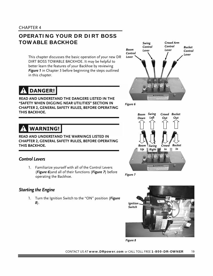
Boom Control Lever
Figure 6
Swing Control Lever
Crowd Arm Control Lever
Bucket Control Lever
CHAPTER 4
OPERATING YOUR DR DIRT BOSS TOWABLE BACKHOE
This chapter discusses the basic operation of your new DR DIRT BOSS TOWABLE BACKHOE. It may be helpful to better learn the features of your Backhoe by reviewing Figure 1 in Chapter 3 before beginning the steps outlined in this chapter.
Control Levers
1. Familiarize yourself with all of the Control Levers (Figure 6)and all of their functions (Figure 7) before operating the Backhoe.
Starting the Engine
1. Turn the Ignition Switch to the “ON” position (Figure 8).
Boom Down
Figure 7
Boom Up
Swing Left
Swing Right
Crowd Out
Crowd In
Bucket Out
Bucket In
Ignition Switch
Figure 8
Off
On
READ AND UNDERSTAND THE DANGERS LISTED IN THE “SAFETY WHEN DIGGING NEAR UTILITIES” SECTION IN CHAPTER 2, GENERAL SAFETY RULES, BEFORE OPERATING THIS BACKHOE.
READ AND UNDERSTAND THE WARNINGS LISTED IN CHAPTER 2, GENERAL SAFETY RULES, BEFORE OPERATING THIS BACKHOE.
20 DR® DIRT BOSS™ TOWABLE BACKHOE
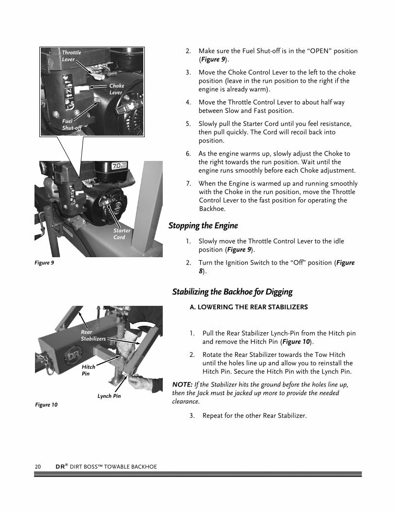
2. Make sure the Fuel Shut-off is in the “OPEN” position (Figure 9).
3. Move the Choke Control Lever to the left to the choke position (leave in the run position to the right if the engine is already warm).
4. Move the Throttle Control Lever to about half way between Slow and Fast position.
5. Slowly pull the Starter Cord until you feel resistance, then pull quickly. The Cord will recoil back into position.
6. As the engine warms up, slowly adjust the Choke to the right towards the run position. Wait until the engine runs smoothly before each Choke adjustment.
7. When the Engine is warmed up and running smoothly with the Choke in the run position, move the Throttle Control Lever to the fast position for operating the Backhoe.
Stopping the Engine
1. Slowly move the Throttle Control Lever to the idle position (Figure 9).
2. Turn the Ignition Switch to the “Off” position (Figure 8).
Stabilizing the Backhoe for Digging
A. LOWERING THE REAR STABILIZERS
1. Pull the Rear Stabilizer Lynch-Pin from the Hitch pin and remove the Hitch Pin (Figure 10).
2. Rotate the Rear Stabilizer towards the Tow Hitch until the holes line up and allow you to reinstall the Hitch Pin. Secure the Hitch Pin with the Lynch Pin.
NOTE: If the Stabilizer hits the ground before the holes line up, then the Jack must be jacked up more to provide the needed clearance.
3. Repeat for the other Rear Stabilizer.
Throttle Lever
Figure 9
Choke Lever
Fuel Shut-off
Starter Cord
Hitch Pin
Figure 10
Lynch Pin
Rear Stabilizers

CONTACT US AT www.DRpower.com or CALL TOLL FREE 1-800-DR-OWNER 21
Hitch Pin
Figure 13
Hitch Pin
Hitch Pin Storage
4. Lower the rear of the Backhoe to the ground by cranking the Jack Handle counterclockwise (Figure 11).
5. Pull the Lock Pin of the Jack and rotate the Jack counterclockwise until the Lock Pin locks the Jack into the horizontal position (Figure 12).
B. LOWERING THE FRONT STABILIZERS
NOTE: When using the Backhoe for the first time after initial setup, you must first cycle the Hydraulic Fluid into the cylinders before you can control the Boom effectively and have it stay in position when the Control Levers are released.
1. Start the Engine as instructed in the “Starting the Engine” section in this chapter.
NOTE: Refer to Figures 6 and 7 for Control Lever functions.
2. Pull back on the Boom Control Lever until you see the Boom move towards you. When the Boom is moved to this position, pressure is removed from the Boom Hitch Pins.
3. Remove the Lynch Pins from the two Hitch Pins and remove the Hitch Pins from the Boom (Figure 13).
4. Install the two Hitch Pins into the storage holes in the Boom and secure with the Lynch Pins.
Figure 11
Jack
Figure 12
Jack Locking Pin

22 DR® DIRT BOSS™ TOWABLE BACKHOE
5. Push the Swing Control Lever slowly all the way forward and pull all the way back four to six times to fill the Swing Cylinder with fluid.
6. Push the Bucket Control Lever slowly all the way forward and pull all the way back four to six times to fill the Bucket Cylinder with fluid.
7. Push the Crowd Arm Control Lever slowly all the way forward and pull all the way back four to six times to fill the Crowd Arm Cylinder with fluid.
8. Push the Boom Control Lever slowly forward (do not push full forward) to slowly fill the Boom Cylinder the rest of the way and lower the Boom.
9. Pull the Boom Control Lever slowly all the way back and push all the way forward four to six times to fill the Boom Cylinder with fluid.
10. Center the Boom and slowly lower the Bucket to the ground and lift the front of the Backhoe until the Wheels are about 6" off the ground (Figure 14).
11. Carefully get off the Backhoe and shut down the engine.
12. Pull the Front Stabilizer Lynch-Pin from the Hitch pin and remove the Hitch Pin (Figure 15).
13. Lower the Front Stabilizer to the ground.
14. Line up the holes in the Front Stabilizer and insert the Hitch Pin. Secure the Hitch Pin with the Lynch Pin (Figure 16).
15. Repeat the last three steps for the other Front Stabilizer.
Figure 14
Approx. 6" off ground
Figure 16
Front Stabilizer
Lynch Pin
Hitch Pin
Figure 15
Front Stabilizer
Lynch Pin
Hitch Pin
WHEN THE FRONT STABILIZERS ARE LOWERED OR RAISED THERE IS A HAZARD OF PINCHING YOUR HANDS. KEEP YOUR HANDS CLEAR OF THE PINCH POINT AREAS AS INDICATED BY THE LABELS.
CONTACT US AT www.DRpower.com or CALL TOLL FREE 1-800-DR-OWNER 23
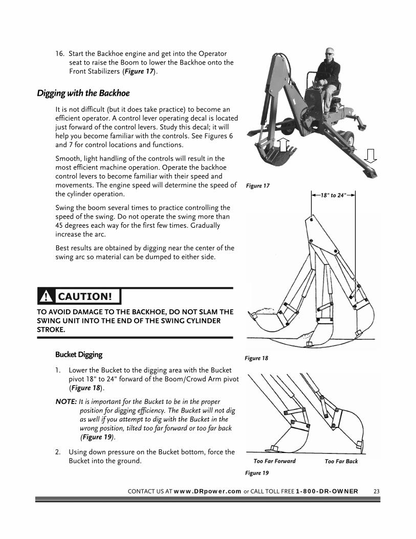
16. Start the Backhoe engine and get into the Operator seat to raise the Boom to lower the Backhoe onto the Front Stabilizers (Figure 17).
Digging with the Backhoe
It is not difficult (but it does take practice) to become an efficient operator. A control lever operating decal is located just forward of the control levers. Study this decal; it will help you become familiar with the controls. See Figures 6 and 7 for control locations and functions.
Smooth, light handling of the controls will result in the most efficient machine operation. Operate the backhoe control levers to become familiar with their speed and movements. The engine speed will determine the speed of the cylinder operation.
Swing the boom several times to practice controlling the speed of the swing. Do not operate the swing more than 45 degrees each way for the first few times. Gradually increase the arc.
Best results are obtained by digging near the center of the swing arc so material can be dumped to either side.
Bucket Digging
1. Lower the Bucket to the digging area with the Bucket pivot 18" to 24" forward of the Boom/Crowd Arm pivot (Figure 18).
NOTE: It is important for the Bucket to be in the proper position for digging efficiency. The Bucket will not dig as well if you attempt to dig with the Bucket in the wrong position, tilted too far forward or too far back (Figure 19).
2. Using down pressure on the Bucket bottom, force the Bucket into the ground.
Figure 18
18" to 24"
TO AVOID DAMAGE TO THE BACKHOE, DO NOT SLAM THE SWING UNIT INTO THE END OF THE SWING CYLINDER STROKE.
Figure 17
Too Far Forward Too Far Back
Figure 19
24 DR® DIRT BOSS™ TOWABLE BACKHOE
3. With the Bucket in the ground, simultaneously retract the Crowd Arm and load the Bucket until it is full (Figure 18).
4. If the Bucket stalls, raise the Boom slightly and continue to dig until the Bucket is full.
5. Raise the Bucket to the top of the trench and dump it on the spoil pile.
6. When lifting the loaded Bucket high, continue rolling the Bucket in as it is being raised to prevent spilling the contents.
NOTE: With a little practice, raising, swinging, and dumping can be accomplished in one smooth operation.
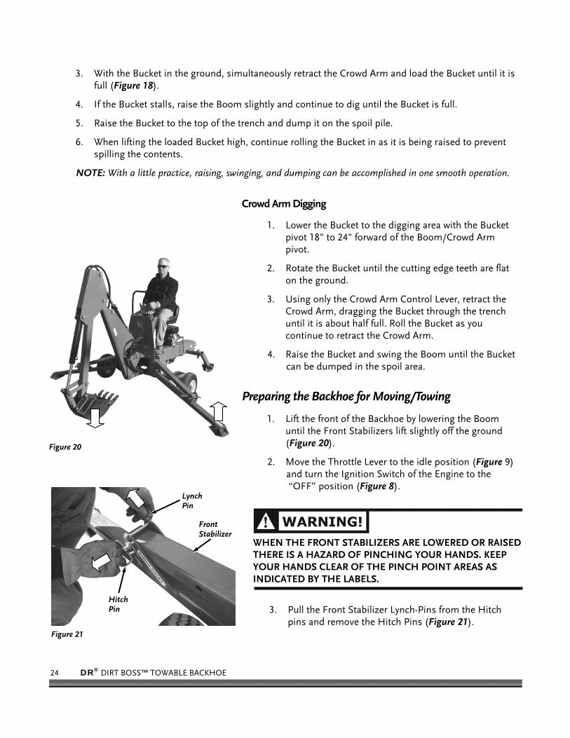
Crowd Arm Digging
1. Lower the Bucket to the digging area with the Bucket pivot 18" to 24" forward of the Boom/Crowd Arm pivot.
2. Rotate the Bucket until the cutting edge teeth are flat on the ground.
3. Using only the Crowd Arm Control Lever, retract the Crowd Arm, dragging the Bucket through the trench until it is about half full. Roll the Bucket as you continue to retract the Crowd Arm.
4. Raise the Bucket and swing the Boom until the Bucket can be dumped in the spoil area.
Preparing the Backhoe for Moving/Towing
1. Lift the front of the Backhoe by lowering the Boom until the Front Stabilizers lift slightly off the ground (Figure 20).
2. Move the Throttle Lever to the idle position (Figure 9) and turn the Ignition Switch of the Engine to the “OFF” position (Figure 8).
3. Pull the Front Stabilizer Lynch-Pins from the Hitch pins and remove the Hitch Pins (Figure 21).
Figure 20
Figure 21
Front Stabilizer
Lynch Pin
Hitch Pin
WHEN THE FRONT STABILIZERS ARE LOWERED OR RAISED THERE IS A HAZARD OF PINCHING YOUR HANDS. KEEP YOUR HANDS CLEAR OF THE PINCH POINT AREAS AS INDICATED BY THE LABELS.
CONTACT US AT www.DRpower.com or CALL TOLL FREE 1-800-DR-OWNER 25
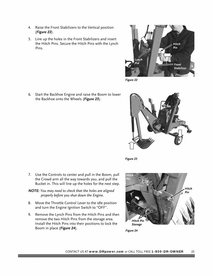
Hitch Pin
Figure 24
Hitch Pin
Hitch Pin Storage
4. Raise the Front Stabilizers to the Vertical position (Figure 22).
5. Line up the holes in the Front Stabilizers and insert the Hitch Pins. Secure the Hitch Pins with the Lynch Pins.
6. Start the Backhoe Engine and raise the Boom to lower the Backhoe onto the Wheels (Figure 23).
7. Use the Controls to center and pull in the Boom, pull the Crowd arm all the way towards you, and pull the Bucket in. This will line up the holes for the next step.
NOTE: You may need to check that the holes are aligned properly before you shut down the Engine.
8. Move the Throttle Control Lever to the idle position and turn the Engine Ignition Switch to “OFF”.
9. Remove the Lynch Pins from the Hitch Pins and then remove the two Hitch Pins from the storage area. Install the Hitch Pins into their positions to lock the Boom in place (Figure 24).
Figure 22
Front Stabilizer
Lynch Pin
Hitch Pin
Figure 23
26 DR® DIRT BOSS™ TOWABLE BACKHOE
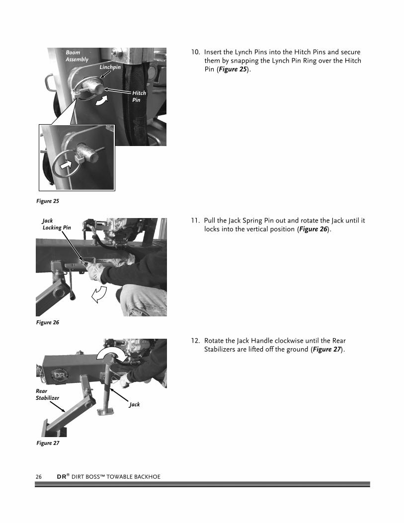
10. Insert the Lynch Pins into the Hitch Pins and secure them by snapping the Lynch Pin Ring over the Hitch Pin (Figure 25).
11. Pull the Jack Spring Pin out and rotate the Jack until it locks into the vertical position (Figure 26).
12. Rotate the Jack Handle clockwise until the Rear Stabilizers are lifted off the ground (Figure 27).
Figure 25
Linchpin
Hitch Pin
Boom Assembly
Figure 26
Jack Locking Pin
Figure 27
Jack
Rear Stabilizer

CONTACT US AT www.DRpower.com or CALL TOLL FREE 1-800-DR-OWNER 27
13. Remove the Hitch Pins of the Rear Stabilizers and rotate them into their upright position until the holes are aligned (Figure 28).
14. Reinstall Hitch Pins into the Rear Stabilizers and secure with the Lynch Pins.
Towing the Backhoe
The Backhoe must be prepared for towing by following the procedures in the previous “Preparing the Backhoe for Towing” section first.
1. Position the Backhoe behind the tow vehicle and raise or lower the Jack to position the Tow Hitch just over the Tow Ball (Figure 29).
2. Pull the Latch Assembly of the Tow Hitch Assembly up and into the open position.
3. Lower the Hitch Coupler of the Backhoe onto the tow vehicle’s Tow Ball (must be a 2" tow ball) by lowering the Jack until all the weight is on the Tow Ball and the Jack Base comes off the ground (Figure 30).
Hitch Pin
Figure 28
Lynch Pin
Rear Stabilizers
Figure 29
Tow Hitch Assembly
2" Tow Ball
Latch Assembly
Figure 30
Tow Hitch Assembly
Jack Base Tow Ball
Jack Handle
28 DR® DIRT BOSS™ TOWABLE BACKHOE
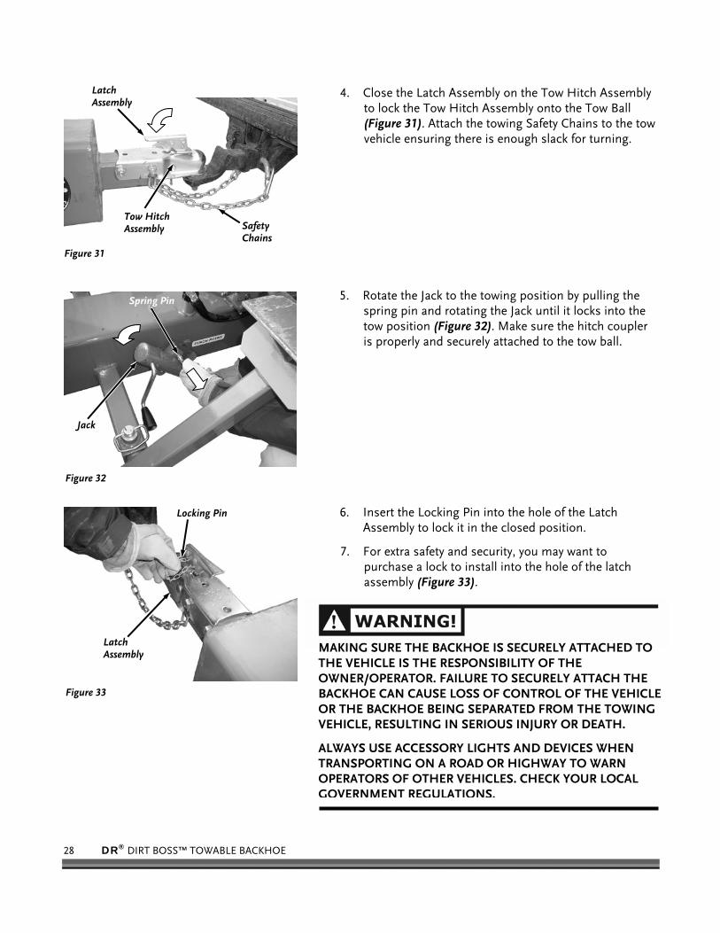
4. Close the Latch Assembly on the Tow Hitch Assembly to lock the Tow Hitch Assembly onto the Tow Ball (Figure 31). Attach the towing Safety Chains to the tow vehicle ensuring there is enough slack for turning.
5. Rotate the Jack to the towing position by pulling the spring pin and rotating the Jack until it locks into the tow position (Figure 32). Make sure the hitch coupler is properly and securely attached to the tow ball.
6. Insert the Locking Pin into the hole of the Latch Assembly to lock it in the closed position.
7. For extra safety and security, you may want to purchase a lock to install into the hole of the latch assembly (Figure 33).
MAKING SURE THE BACKHOE IS SECURELY ATTACHED TO THE VEHICLE IS THE RESPONSIBILITY OF THE OWNER/OPERATOR. FAILURE TO SECURELY ATTACH THE BACKHOE CAN CAUSE LOSS OF CONTROL OF THE VEHICLE OR THE BACKHOE BEING SEPARATED FROM THE TOWING VEHICLE, RESULTING IN SERIOUS INJURY OR DEATH.
ALWAYS USE ACCESSORY LIGHTS AND DEVICES WHEN TRANSPORTING ON A ROAD OR HIGHWAY TO WARN OPERATORS OF OTHER VEHICLES. CHECK YOUR LOCAL GOVERNMENT REGULATIONS.
Figure 31
Tow Hitch Assembly
Latch Assembly
Safety Chains
Figure 32
Jack
Spring Pin
Figure 33
Latch Assembly
Locking Pin
CONTACT US AT www.DRpower.com or CALL TOLL FREE 1-800-DR-OWNER 29
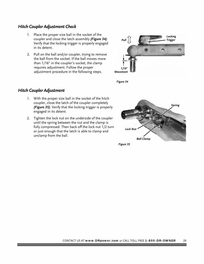
Hitch Coupler Adjustment Check
1. Place the proper size ball in the socket of the coupler and close the latch assembly (Figure 34). Verify that the locking trigger is properly engaged in its detent.
2. Pull on the ball and/or coupler, trying to remove the ball from the socket. If the ball moves more than 1/16" in the coupler’s socket, the clamp requires adjustment. Follow the proper adjustment procedure in the following steps.
Hitch Coupler Adjustment
1. With the proper size ball in the socket of the hitch coupler, close the latch of the coupler completely (Figure 35). Verify that the locking trigger is properly engaged in its detent.
2. Tighten the lock nut on the underside of the coupler until the spring between the nut and the clamp is fully compressed. Then back off the lock nut 1/2 turn or just enough that the latch is able to clamp and unclamp from the ball.
Figure 35
Lock Nut
Ball Clamp
Spring
Figure 34
Pull Locking Trigger
1/16" Movement

30 DR® DIRT BOSS™ TOWABLE BACKHOE
CONTACT US AT www.DRpower.com or CALL TOLL FREE 1-800-DR-OWNER 31
CHAPTER 5
MAINTAINING THE DR DIRT BOSS TOWABLE BACKHOE
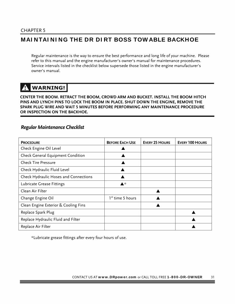
Regular maintenance is the way to ensure the best performance and long life of your machine. Please refer to this manual and the engine manufacturer's owner's manual for maintenance procedures. Service intervals listed in the checklist below supersede those listed in the engine manufacturer's owner's manual.
Regular Maintenance Checklist
*Lubricate grease fittings after every four hours of use.
PROCEDURE BEFORE EACH USE EVERY 25 HOURS EVERY 100 HOURS Check Engine Oil Level �
Check General Equipment Condition �
Check Tire Pressure �
Check Hydraulic Fluid Level
Check Hydraulic Hoses and Connections
Lubricate Grease Fittings *
Clean Air Filter
Change Engine Oil 1st time 5 hours
Clean Engine Exterior & Cooling Fins
Replace Spark Plug
Replace Hydraulic Fluid and Filter
Replace Air Filter
CENTER THE BOOM. RETRACT THE BOOM, CROWD ARM AND BUCKET. INSTALL THE BOOM HITCH PINS AND LYNCH PINS TO LOCK THE BOOM IN PLACE. SHUT DOWN THE ENGINE, REMOVE THE SPARK PLUG WIRE AND WAIT 5 MINUTES BEFORE PERFORMING ANY MAINTENANCE PROCEDURE OR INSPECTION ON THE BACKHOE.
32 DR® DIRT BOSS™ TOWABLE BACKHOE
Figure 36
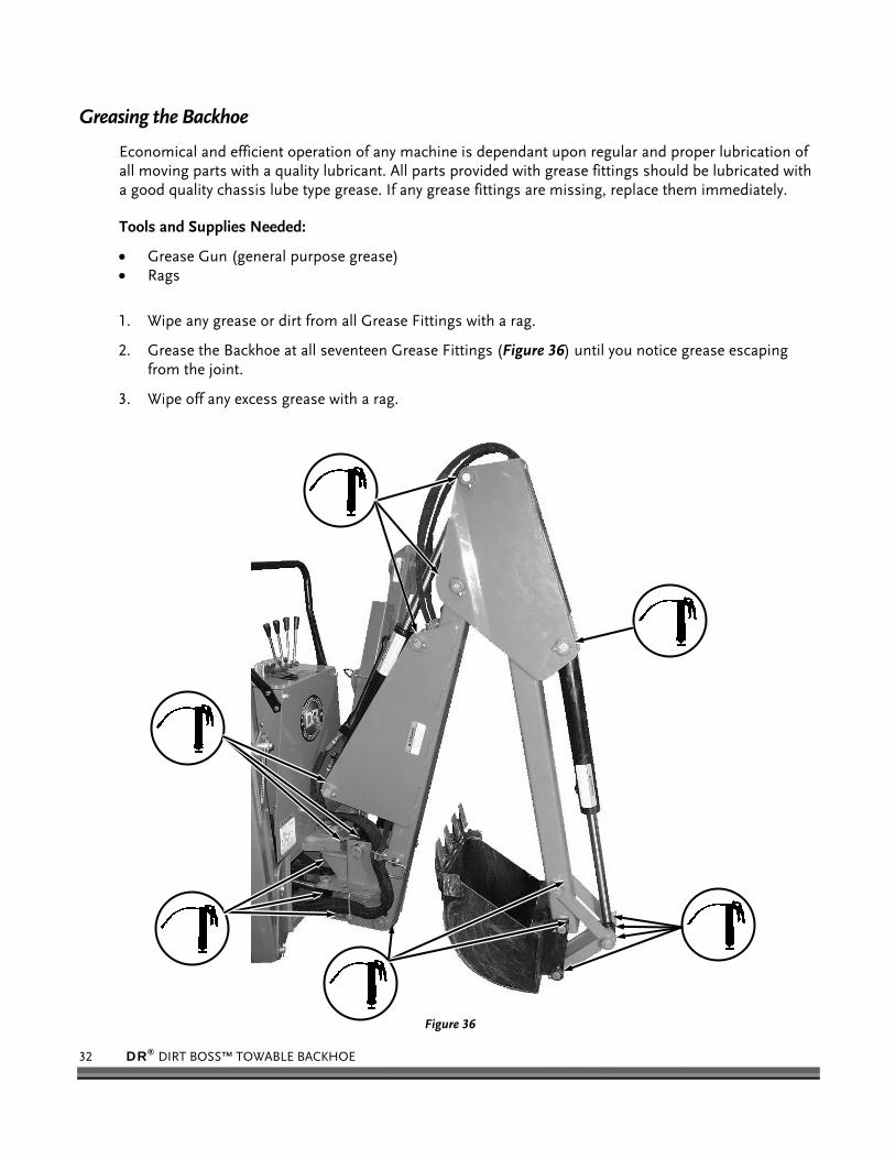
Greasing the Backhoe
Economical and efficient operation of any machine is dependant upon regular and proper lubrication of all moving parts with a quality lubricant. All parts provided with grease fittings should be lubricated with a good quality chassis lube type grease. If any grease fittings are missing, replace them immediately.
Tools and Supplies Needed:
• Grease Gun (general purpose grease) • Rags
1. Wipe any grease or dirt from all Grease Fittings with a rag.
2. Grease the Backhoe at all seventeen Grease Fittings (Figure 36) until you notice grease escaping from the joint.
3. Wipe off any excess grease with a rag.
CONTACT US AT www.DRpower.com or CALL TOLL FREE 1-800-DR-OWNER 33
Changing the Hydraulic Fluid and Filter
Tools needed:
• 3/4"Wrench • 7/8" Wrench • Filter Wrench
1. Place a waste fluid container under Filter and Connections. Your container must be large enough to hold the 12.46 gallons of fluid in the Tank.
2. Slightly raise the hitch end of the Backhoe by turning the Jack Handle clockwise. The hitch end of the Hydraulic Tank should be slightly higher than the Filter end.
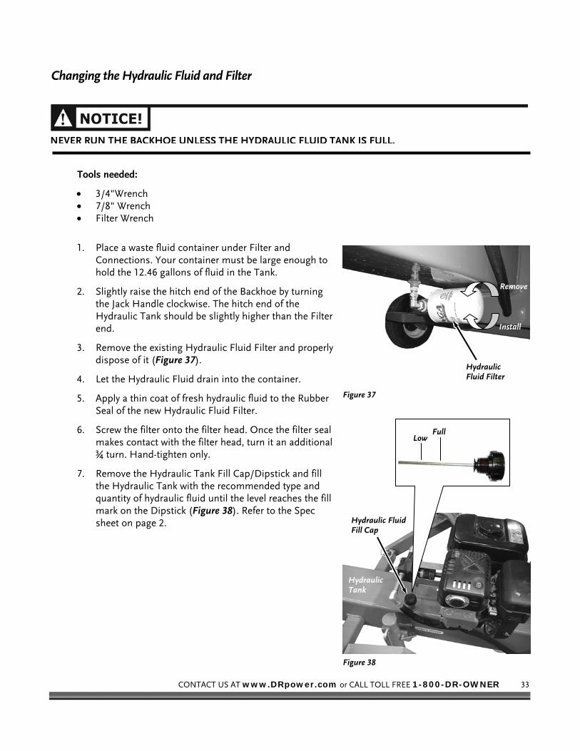
3. Remove the existing Hydraulic Fluid Filter and properly dispose of it (Figure 37).
4. Let the Hydraulic Fluid drain into the container.
5. Apply a thin coat of fresh hydraulic fluid to the Rubber Seal of the new Hydraulic Fluid Filter.
6. Screw the filter onto the filter head. Once the filter seal makes contact with the filter head, turn it an additional ¾ turn. Hand-tighten only.
7. Remove the Hydraulic Tank Fill Cap/Dipstick and fill the Hydraulic Tank with the recommended type and quantity of hydraulic fluid until the level reaches the fill mark on the Dipstick (Figure 38). Refer to the Spec sheet on page 2.
NEVER RUN THE BACKHOE UNLESS THE HYDRAULIC FLUID TANK IS FULL.
Hydraulic Fluid Fill Cap
Figure 38
Hydraulic Tank
Full Low
Figure 37
Hydraulic Fluid Filter
Remove
Install
34 DR® DIRT BOSS™ TOWABLE BACKHOE
End of Season and Storage
• Coat the exposed piston rods of all hydraulic cylinders with a grease or corrosion preventative.
• Lubricate all grease fittings (See page 32).
• Clean the exterior of the unit to remove all dirt, grease, and any other foreign material. To prevent rust, touch up painted surfaces that have been scratched or chipped.
• If possible, store the Backhoe in a dry, protected place. If it is necessary to store the Backhoe outside, cover it with a protective material (especially the Engine and Seat).
CENTER THE BOOM. RETRACT THE BOOM, CROWD ARM AND BUCKET. INSTALL THE BOOM HITCH PINS AND LYNCH PINS TO LOCK THE BOOM IN PLACE. SHUT DOWN THE ENGINE, REMOVE THE SPARK PLUG WIRE AND WAIT 5 MINUTES BEFORE PERFORMING ANY MAINTENANCE PROCEDURE OR INSPECTION ON THE BACKHOE.
CONTACT US AT www.DRpower.com or CALL TOLL FREE 1-800-DR-OWNER 35
CHAPTER 6
TROUBLESHOOTING
Most problems are easy to fix. Consult the Troubleshooting Table below for common problems and their solutions. If you continue to experience problems, call DR Power Equipment for support.
Troubleshooting Table
SYMPTOM POSSIBLE CAUSE Backhoe fails to lift or swing.
⇒ Low hydraulic fluid supply; Add fluid.
⇒ Pump not running; Start engine.
⇒ Worn control valve; Replace or repair worn valve.
⇒ Pump damaged or worn; Replace pump.
⇒ Broken hydraulic line; Check for leaks, replace line.
⇒ Faulty relief valve; Clean or replace relief valve.
⇒ Bent piston rod; repair or replace cylinder.
Backhoe lifting or swinging too slowly.
⇒ Cold hydraulic fluid; Warm fluid with engine at idle.
⇒ Engine speed too low; Open throttle
⇒ Hydraulic fluid leaking past control valve; repair or replace worn valve.
⇒ Hydraulic fluid too heavy; Use recommended fluid.
⇒ Scored Cylinder; Replace cylinder.
⇒ Pump damaged or worn; Repair or replace pump.
⇒ Hydraulic fluid leaking past cylinder packings; Replace packings.
⇒ Pinched supply hose; Replace hose, rout to prevent kinking or pinching.
Backhoe fails to hold up the load.
NOTE: All loads will settle down over a period of time. This is normal.
⇒ Broken hydraulic lines; Check for leaks and replace line.
⇒ Hydraulic fluid leaking past cylinder packings; Replace packings.
⇒ Hydraulic fluid leaking past control valve; repair or replace worn valve.
CENTER THE BOOM. RETRACT THE BOOM, CROWD ARM AND BUCKET. INSTALL THE BOOM HITCH PINS AND LYNCH PINS TO LOCK THE BOOM IN PLACE. SHUT DOWN THE ENGINE, REMOVE THE SPARK PLUG WIRE AND WAIT 5 MINUTES BEFORE PERFORMING ANY MAINTENANCE PROCEDURE OR INSPECTION ON THE BACKHOE.
36 DR® DIRT BOSS™ TOWABLE BACKHOE
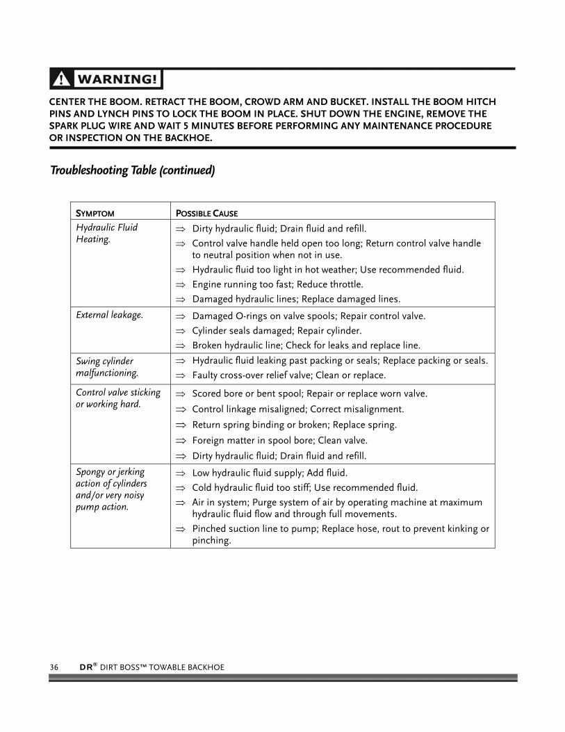
Troubleshooting Table (continued)
SYMPTOM POSSIBLE CAUSE Hydraulic Fluid Heating.
⇒ Dirty hydraulic fluid; Drain fluid and refill.
⇒ Control valve handle held open too long; Return control valve handle to neutral position when not in use.
⇒ Hydraulic fluid too light in hot weather; Use recommended fluid.
⇒ Engine running too fast; Reduce throttle.
⇒ Damaged hydraulic lines; Replace damaged lines.
External leakage. ⇒ Damaged O-rings on valve spools; Repair control valve.
⇒ Cylinder seals damaged; Repair cylinder.
⇒ Broken hydraulic line; Check for leaks and replace line.
Swing cylinder malfunctioning.
⇒ Hydraulic fluid leaking past packing or seals; Replace packing or seals.
⇒ Faulty cross-over relief valve; Clean or replace.
Control valve sticking or working hard.
⇒ Scored bore or bent spool; Repair or replace worn valve.
⇒ Control linkage misaligned; Correct misalignment.
⇒ Return spring binding or broken; Replace spring.
⇒ Foreign matter in spool bore; Clean valve. ⇒ Dirty hydraulic fluid; Drain fluid and refill.
Spongy or jerking action of cylinders and/or very noisy pump action.
⇒ Low hydraulic fluid supply; Add fluid.
⇒ Cold hydraulic fluid too stiff; Use recommended fluid.
⇒ Air in system; Purge system of air by operating machine at maximum hydraulic fluid flow and through full movements.
⇒ Pinched suction line to pump; Replace hose, rout to prevent kinking or pinching.
CENTER THE BOOM. RETRACT THE BOOM, CROWD ARM AND BUCKET. INSTALL THE BOOM HITCH PINS AND LYNCH PINS TO LOCK THE BOOM IN PLACE. SHUT DOWN THE ENGINE, REMOVE THE SPARK PLUG WIRE AND WAIT 5 MINUTES BEFORE PERFORMING ANY MAINTENANCE PROCEDURE OR INSPECTION ON THE BACKHOE.
CONTACT US AT www.DRpower.com or CALL TOLL FREE 1-800-DR-OWNER 37
CHAPTER 7
DR DIRT BOSS TOWABLE BACKHOE ACCESSORIES
The optional Buckets and Digging Tooth provide more options for the type of digging you do by enabling a choice of larger or smaller amounts of earth that can be loosened or moved.
Tools and Supplies Needed:
• Two 7/16" wrenches • Hammer • Brass Drift Punch • Wood Blocks • Safety Glasses
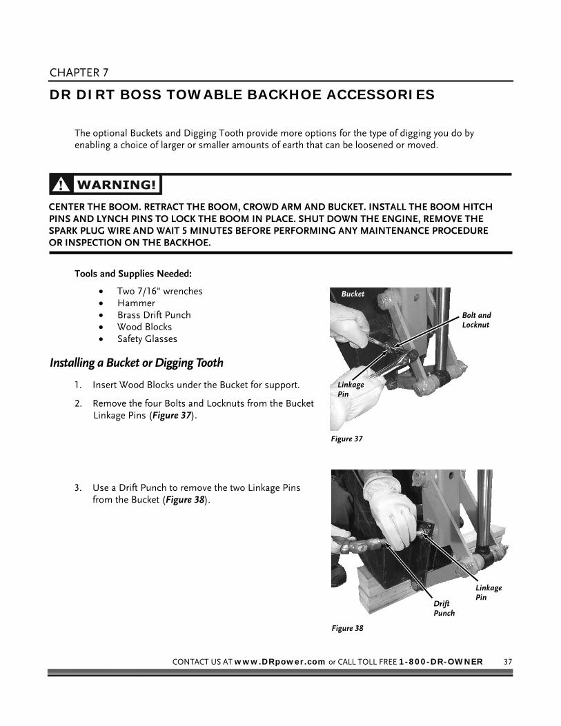
Installing a Bucket or Digging Tooth
1. Insert Wood Blocks under the Bucket for support.
2. Remove the four Bolts and Locknuts from the Bucket Linkage Pins (Figure 37).
3. Use a Drift Punch to remove the two Linkage Pins from the Bucket (Figure 38).
Figure 37
Bolt and Locknut
Bucket
Linkage Pin
Figure 38
Drift Punch
Linkage Pin
CENTER THE BOOM. RETRACT THE BOOM, CROWD ARM AND BUCKET. INSTALL THE BOOM HITCH PINS AND LYNCH PINS TO LOCK THE BOOM IN PLACE. SHUT DOWN THE ENGINE, REMOVE THE SPARK PLUG WIRE AND WAIT 5 MINUTES BEFORE PERFORMING ANY MAINTENANCE PROCEDURE OR INSPECTION ON THE BACKHOE.
38 DR® DIRT BOSS™ TOWABLE BACKHOE
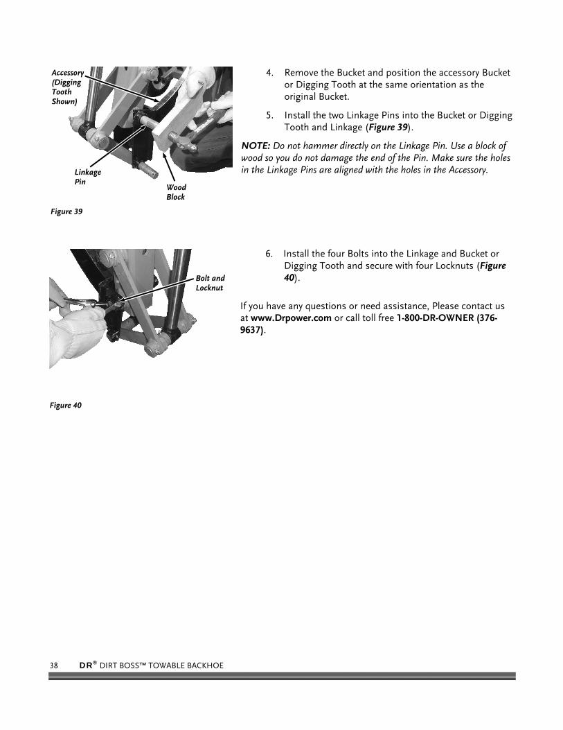
4. Remove the Bucket and position the accessory Bucket or Digging Tooth at the same orientation as the original Bucket.
5. Install the two Linkage Pins into the Bucket or Digging Tooth and Linkage (Figure 39).
NOTE: Do not hammer directly on the Linkage Pin. Use a block of wood so you do not damage the end of the Pin. Make sure the holes in the Linkage Pins are aligned with the holes in the Accessory.
6. Install the four Bolts into the Linkage and Bucket or Digging Tooth and secure with four Locknuts (Figure 40).
If you have any questions or need assistance, Please contact us at www.Drpower.com or call toll free 1-800-DR-OWNER (376-9637).
Figure 39
Linkage Pin
Accessory (Digging Tooth Shown)
Wood Block
Figure 40
Bolt and Locknut

CONTACT US AT www.DRpower.com or CALL TOLL FREE 1-800-DR-OWNER 39
40 DR® DIRT BOSS™ TOWABLE BACKHOE
CHAPTER 8
PARTS LIST AND SCHEMATIC DIAGRAMS
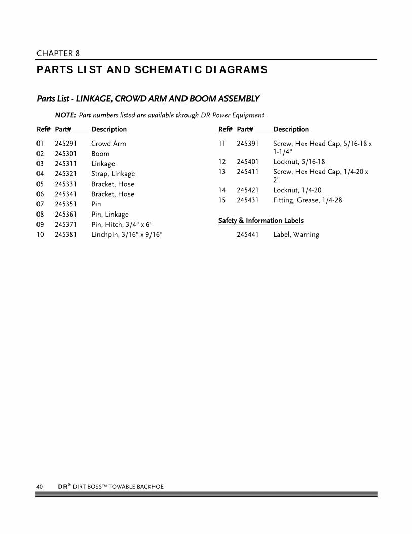
Parts List - LINKAGE, CROWD ARM AND BOOM ASSEMBLY
NOTE: Part numbers listed are available through DR Power Equipment.
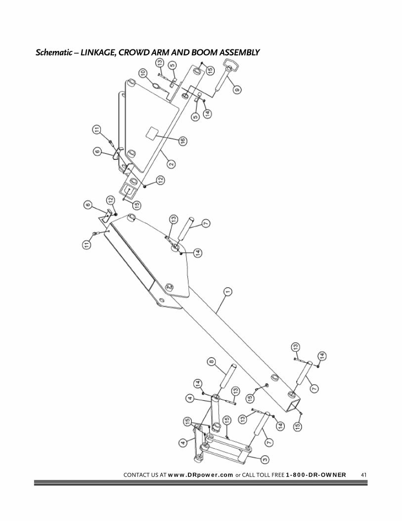
Ref# Part# Description
01 245291 Crowd Arm 02 245301 Boom 03 245311 Linkage 04 245321 Strap, Linkage 05 245331 Bracket, Hose 06 245341 Bracket, Hose 07 245351 Pin 08 245361 Pin, Linkage 09 245371 Pin, Hitch, 3/4" x 6" 10 245381 Linchpin, 3/16" x 9/16"
Ref# Part# Description
11 245391 Screw, Hex Head Cap, 5/16-18 x 1-1/4"
12 245401 Locknut, 5/16-18 13 245411 Screw, Hex Head Cap, 1/4-20 x
2" 14 245421 Locknut, 1/4-20 15 245431 Fitting, Grease, 1/4-28
Safety & Information Labels
245441 Label, Warning
CONTACT US AT www.DRpower.com or CALL TOLL FREE 1-800-DR-OWNER 41
Schematic – LINKAGE, CROWD ARM AND BOOM ASSEMBLY
42 DR® DIRT BOSS™ TOWABLE BACKHOE
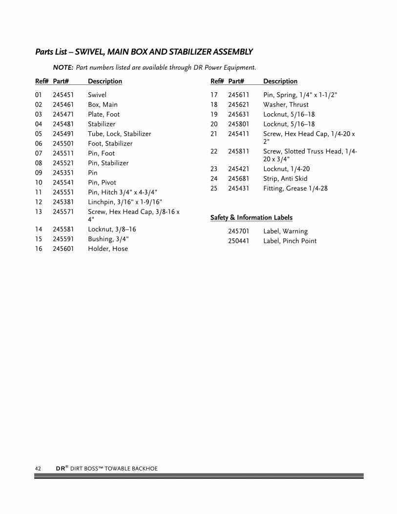
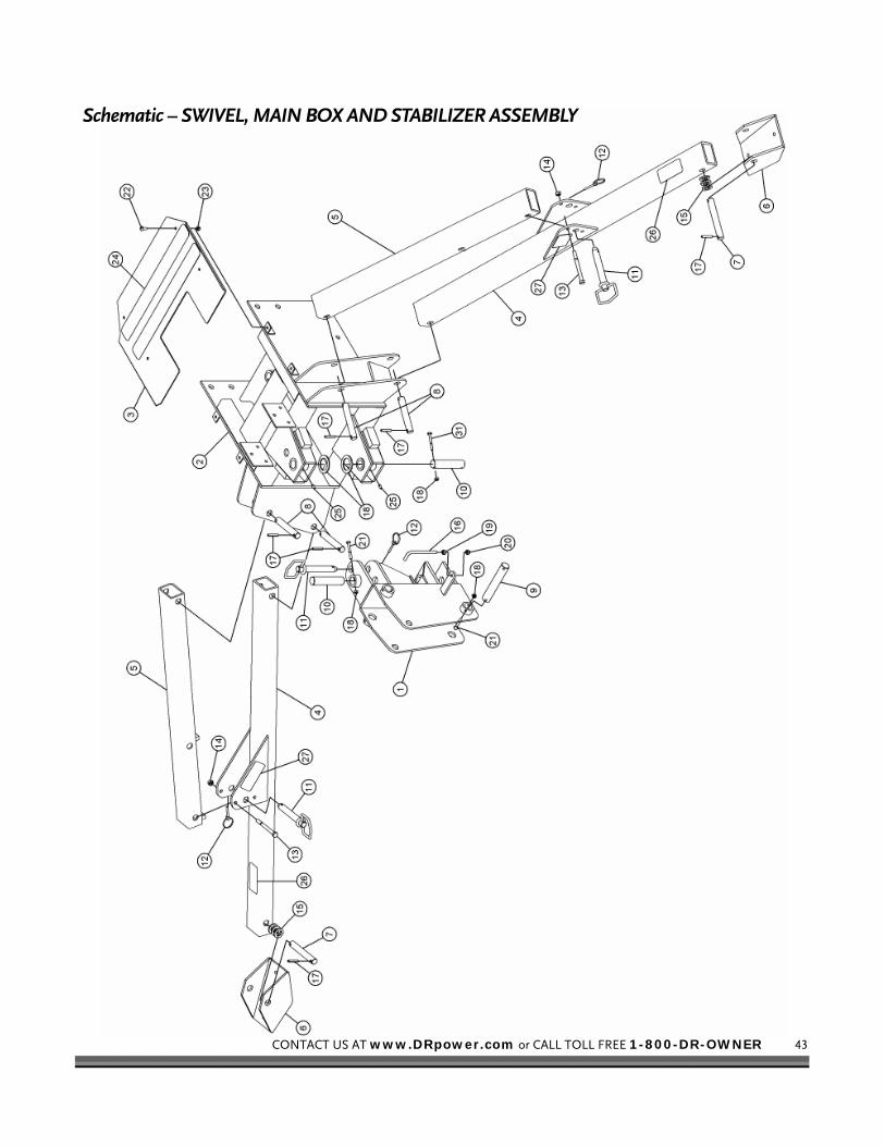
Parts List – SWIVEL, MAIN BOX AND STABILIZER ASSEMBLY
NOTE: Part numbers listed are available through DR Power Equipment.
Ref# Part# Description
01 245451 Swivel 02 245461 Box, Main 03 245471 Plate, Foot 04 245481 Stabilizer 05 245491 Tube, Lock, Stabilizer 06 245501 Foot, Stabilizer 07 245511 Pin, Foot 08 245521 Pin, Stabilizer 09 245351 Pin 10 245541 Pin, Pivot 11 245551 Pin, Hitch 3/4" x 4-3/4" 12 245381 Linchpin, 3/16" x 1-9/16" 13 245571 Screw, Hex Head Cap, 3/8-16 x
4" 14 245581 Locknut, 3/8–16 15 245591 Bushing, 3/4" 16 245601 Holder, Hose
Ref# Part# Description
17 245611 Pin, Spring, 1/4" x 1-1/2" 18 245621 Washer, Thrust 19 245631 Locknut, 5/16–18 20 245801 Locknut, 5/16–18 21 245411 Screw, Hex Head Cap, 1/4-20 x
2" 22 245811 Screw, Slotted Truss Head, 1/4-
20 x 3/4" 23 245421 Locknut, 1/4-20 24 245681 Strip, Anti Skid 25 245431 Fitting, Grease 1/4-28
Safety & Information Labels
245701 Label, Warning 250441 Label, Pinch Point
CONTACT US AT www.DRpower.com or CALL TOLL FREE 1-800-DR-OWNER 43
Schematic – SWIVEL, MAIN BOX AND STABILIZER ASSEMBLY

44 DR® DIRT BOSS™ TOWABLE BACKHOE
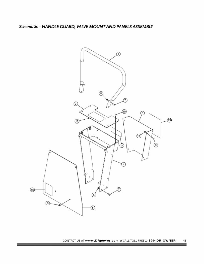
Parts List – HANDLE GUARD, VALVE MOUNT AND PANELS ASSEMBLY
NOTE: Part numbers listed are available through DR Power Equipment.
Ref# Part# Description
01 245731 Guard, Handle 02 245741 Cover, Valve 03 245751 Guard, Hose 04 245761 Mount, Valve 05 245771 Panel, Front 06 245781 Locknut, 3/8–16 07 246791 Screw, Hex Head Cap, 5/16–18 x
3/4" 08 245801 Locknut, 5/16–18 09 245811 Screw, Slotted Truss Head, 1/4-
20 x 3/4"
Ref# Part# Description
10 245821 Screw, Slotted Truss Head, 1/4-20 x 1/2"
11 245421 Locknut, 1/4-20
Safety & Information Labels
250451 Label, Operator 245851 Label, Warning 246041 Label, Warning 245871 Label, Pin Placement
CONTACT US AT www.DRpower.com or CALL TOLL FREE 1-800-DR-OWNER 45
Schematic – HANDLE GUARD, VALVE MOUNT AND PANELS ASSEMBLY
46 DR® DIRT BOSS™ TOWABLE BACKHOE
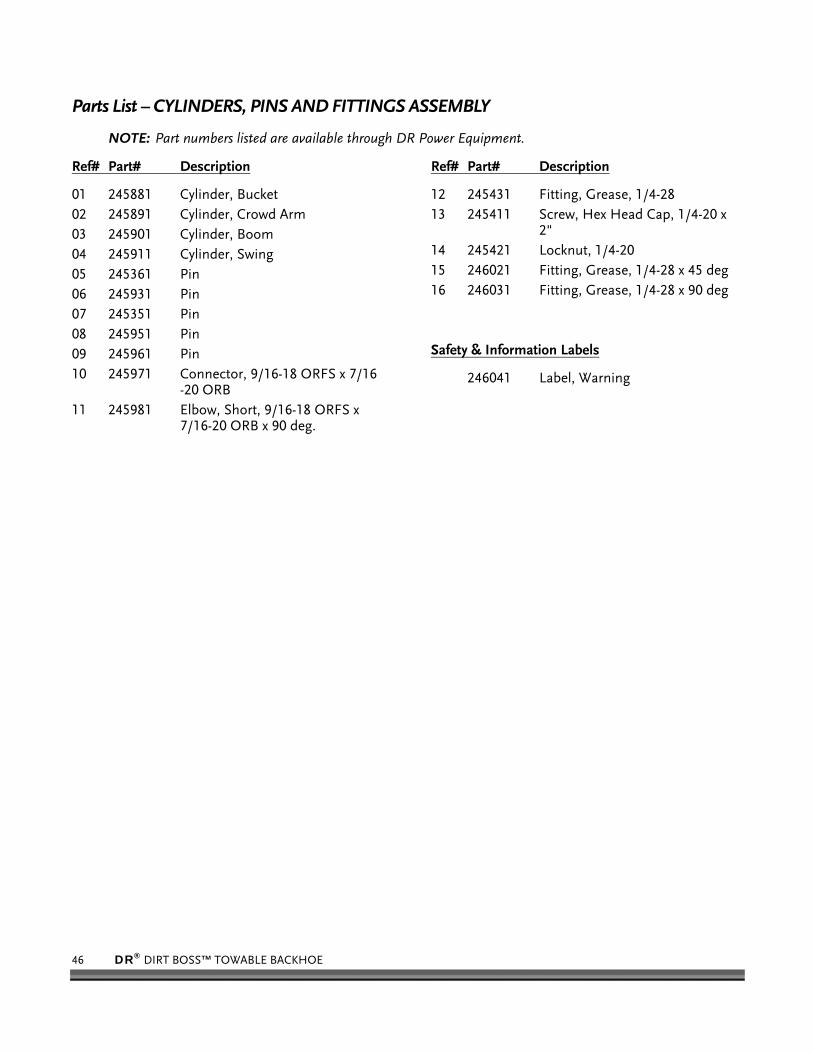
Parts List – CYLINDERS, PINS AND FITTINGS ASSEMBLY
NOTE: Part numbers listed are available through DR Power Equipment.
Ref# Part# Description
01 245881 Cylinder, Bucket 02 245891 Cylinder, Crowd Arm 03 245901 Cylinder, Boom 04 245911 Cylinder, Swing 05 245361 Pin 06 245931 Pin 07 245351 Pin 08 245951 Pin 09 245961 Pin 10 245971 Connector, 9/16-18 ORFS x 7/16
-20 ORB 11 245981 Elbow, Short, 9/16-18 ORFS x
7/16-20 ORB x 90 deg.
Ref# Part# Description
12 245431 Fitting, Grease, 1/4-28 13 245411 Screw, Hex Head Cap, 1/4-20 x
2" 14 245421 Locknut, 1/4-20 15 246021 Fitting, Grease, 1/4-28 x 45 deg 16 246031 Fitting, Grease, 1/4-28 x 90 deg
Safety & Information Labels
246041 Label, Warning

CONTACT US AT www.DRpower.com or CALL TOLL FREE 1-800-DR-OWNER 47
Schematic – CYLINDERS, PINS AND FITTINGS ASSEMBLY
48 DR® DIRT BOSS™ TOWABLE BACKHOE
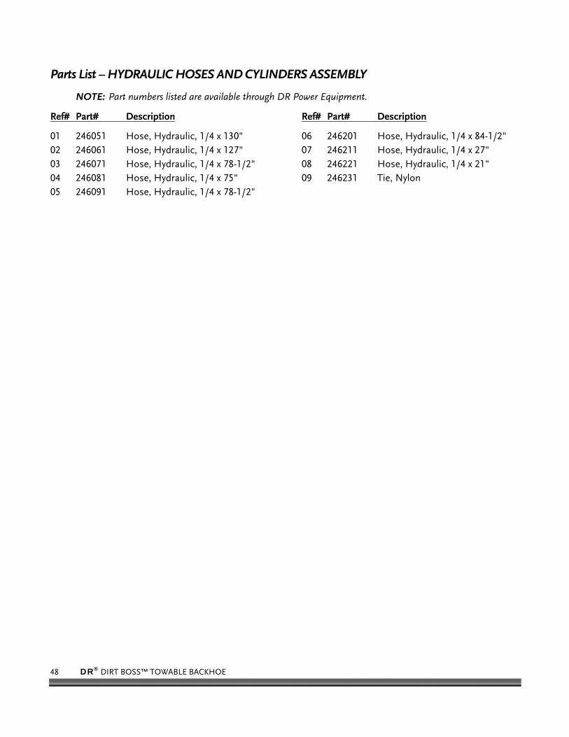
Parts List – HYDRAULIC HOSES AND CYLINDERS ASSEMBLY
NOTE: Part numbers listed are available through DR Power Equipment.
Ref# Part# Description
01 246051 Hose, Hydraulic, 1/4 x 130" 02 246061 Hose, Hydraulic, 1/4 x 127" 03 246071 Hose, Hydraulic, 1/4 x 78-1/2" 04 246081 Hose, Hydraulic, 1/4 x 75" 05 246091 Hose, Hydraulic, 1/4 x 78-1/2"
Ref# Part# Description
06 246201 Hose, Hydraulic, 1/4 x 84-1/2" 07 246211 Hose, Hydraulic, 1/4 x 27" 08 246221 Hose, Hydraulic, 1/4 x 21" 09 246231 Tie, Nylon
CONTACT US AT www.DRpower.com or CALL TOLL FREE 1-800-DR-OWNER 49
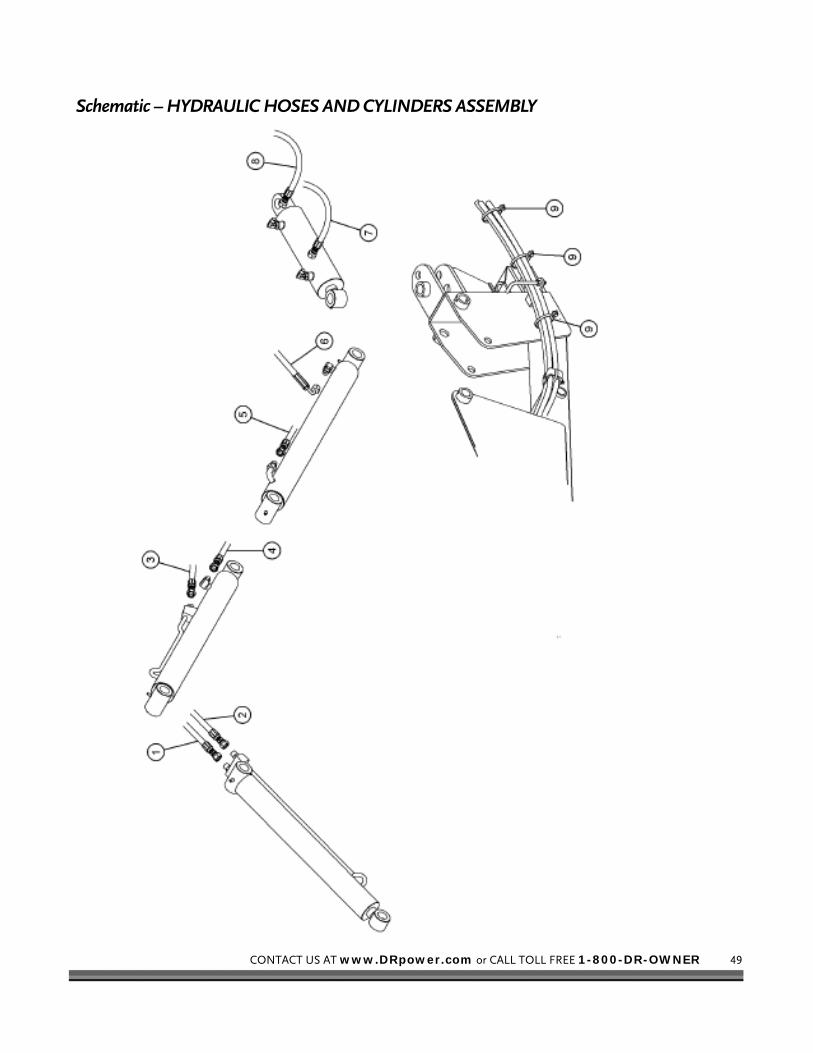
Schematic – HYDRAULIC HOSES AND CYLINDERS ASSEMBLY

50 DR® DIRT BOSS™ TOWABLE BACKHOE
Parts List – VALVE AND FITTINGS ASSEMBLY
NOTE: Part numbers listed are available through DR Power Equipment.
Ref# Part# Description
01 246241 Valve, 4 Spool 02 246251 Handle Assembly 03 246261 Handle Assembly 04 246271 Knob 05 246281 Nut, Hex, 8mm–1.25 06 246291 Connector, Straight Thread 07 246301 Elbow, Straight Thread, 90 deg.
Ref# Part# Description
08 246311 Valve, Needle 09 246321 Connector, Swivel, Straight
Thread 10 246331 Screw, Hex Head Cap, 5/16–18 x
1-1/2" 11 245631 Nut, Hex, 5/16–18 12 246351 Lock Washer, 5/16
CONTACT US AT www.DRpower.com or CALL TOLL FREE 1-800-DR-OWNER 51
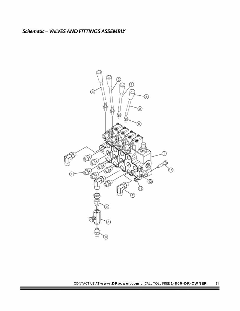
Schematic – VALVES AND FITTINGS ASSEMBLY

52 DR® DIRT BOSS™ TOWABLE BACKHOE
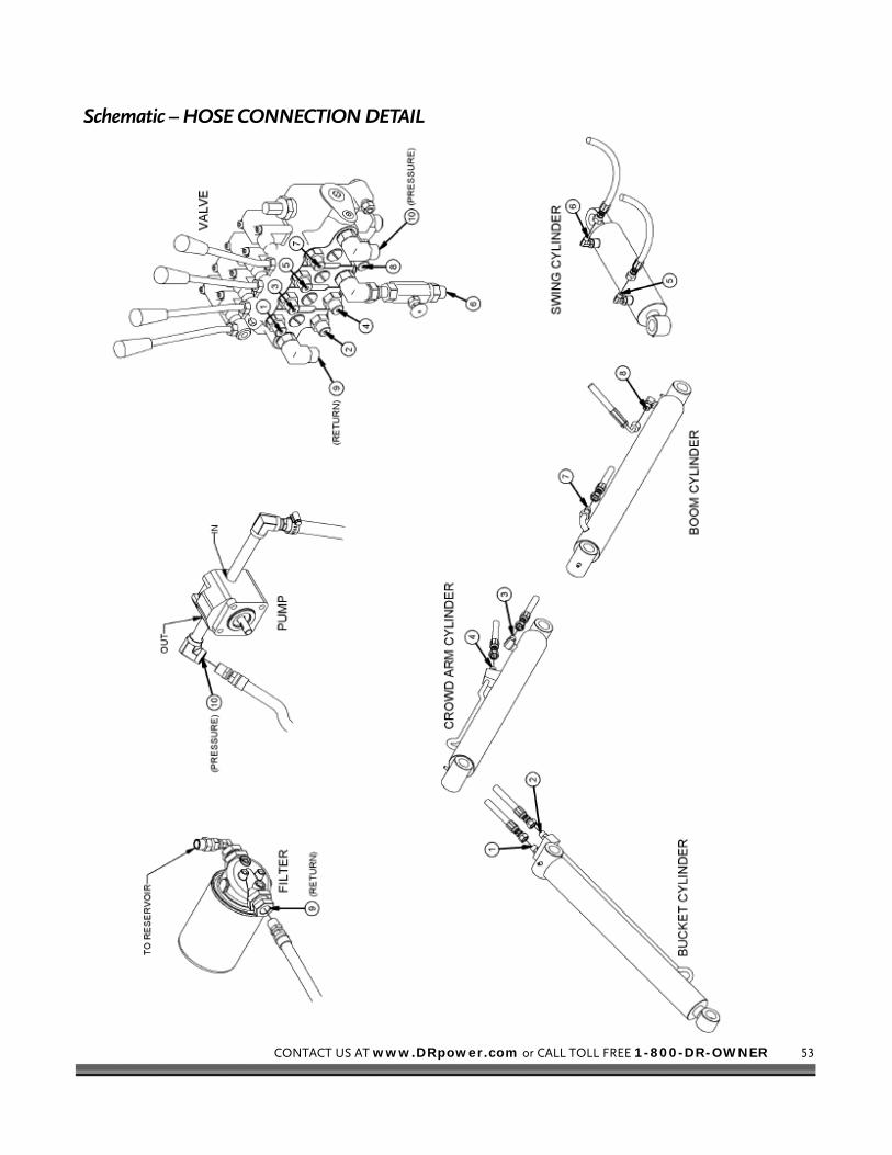
Parts List – HOSE CONNECTION DETAIL
NOTE: This list and schematic are reference for attaching hose ends. Part numbers are listed on other schematics.
Ref# Description
01 Hose, Hydraulic, 1/4 x 130" 02 Hose, Hydraulic, 1/4 x 127" 03 Hose, Hydraulic, 1/4 x 75" 04 Hose, Hydraulic, 1/4 x 78-1/2" 05 Hose, Hydraulic, 1/4 x 27"
Ref# Description
06 Hose, Hydraulic, 1/4 x 21" 07 Hose, Hydraulic, 1/4 x 78-1/2" 08 Hose, Hydraulic, 1/4 x 84-1/2" 09 Hose, Hydraulic, 3/8 x 43" 10 Hose, Hydraulic, 3/8 x 70"
CONTACT US AT www.DRpower.com or CALL TOLL FREE 1-800-DR-OWNER 53
Schematic – HOSE CONNECTION DETAIL
54 DR® DIRT BOSS™ TOWABLE BACKHOE
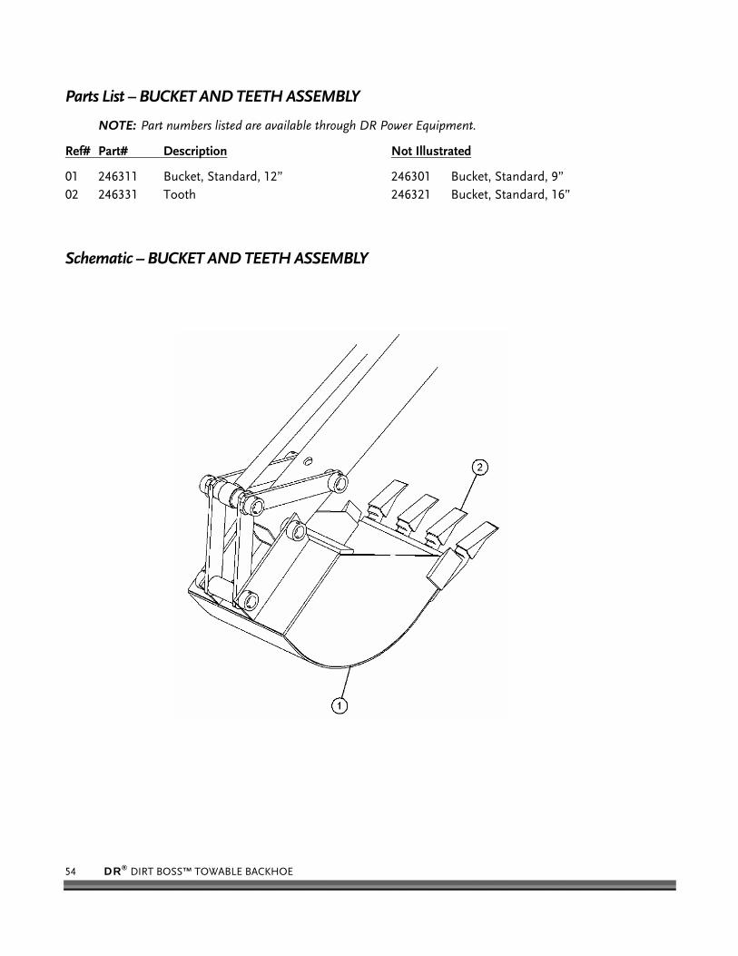
Parts List – BUCKET AND TEETH ASSEMBLY
NOTE: Part numbers listed are available through DR Power Equipment.
Ref# Part# Description
01 246311 Bucket, Standard, 12” 02 246331 Tooth
Not Illustrated
246301 Bucket, Standard, 9” 246321 Bucket, Standard, 16”
Schematic – BUCKET AND TEETH ASSEMBLY

CONTACT US AT www.DRpower.com or CALL TOLL FREE 1-800-DR-OWNER 55
56 DR® BACKHOE
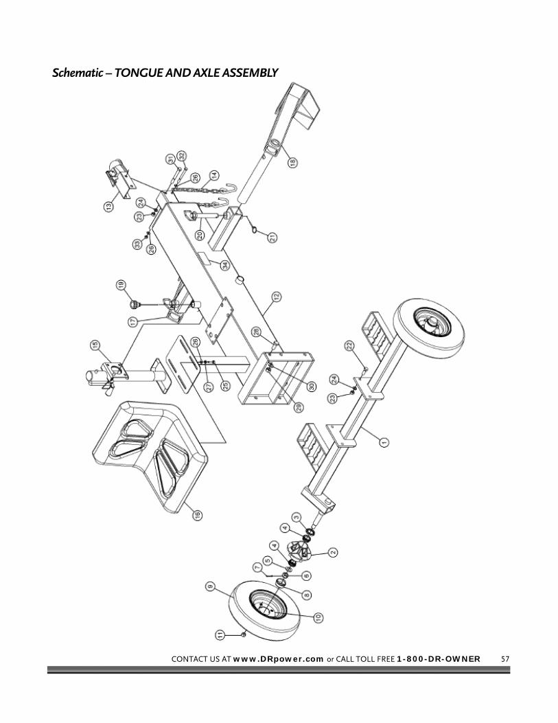
Parts List – TONGUE AND AXLE ASSEMBLY
NOTE: Part numbers listed are available through DR Power Equipment.
Ref# Part# Description
01 246361 Weldment, Axle 02 246371 Hub 03 246381 Seal 04 246391 Bearing 05 246401 Washer 06 246411 Nut 07 246421 Pin, Cotter 08 246431 Cap-Dust 09 246441 Wheel 10 246451 Tire, 4.80-8 11 246461 Nut, Stud, Hub 12 246471 Weldment, Tongue 13 246481 Coupler 14 246491 Chains 15 246501 Jack 16 246511 Seat 17 246521 Stablizer, Rear, R.H. 18 246531 Stablizer, Rear, L.H. 19 246541 Cap, Vent, w/Dipstick 20 246551 Pin, Hitch, 1" x 5-3/4" 21 246561 Linchpin
Ref# Part# Description
22 246571 Screw, Hex Head Cap 1/2-13 x 1-1/2"
23 246581 Locknut, 1/2-13 24 246591 Lockwasher, 1/2" 25 246601 Screw, Hex Head Cap, 3/8–16 x
1" 26 246611 Washer, Flat, 3/8" 27 246621 Lockwasher, 3/8" 28 246631 Screw, Hex Head Cap, 5/8–11 x
1-1/2" 29 246641 Locknut, 5/8–11 30 246651 Lockwasher, 5/8" 31 246661 Screw, Hex Head Cap, 1/2-13 x
4" 32 246671 Screw, Hex Head Cap, 3/8–16 x
4-1/2" 33 245581 Locknut, 3/8–16
Safety & Information Labels
250441 Label, Pinch Point
CONTACT US AT www.DRpower.com or CALL TOLL FREE 1-800-DR-OWNER 57
Schematic – TONGUE AND AXLE ASSEMBLY
58 DR® DIRT BOSS™ TOWABLE BACKHOE
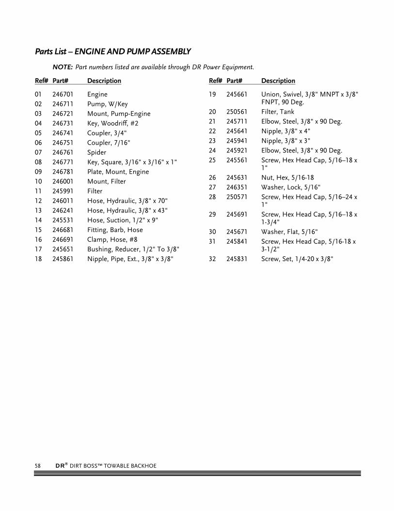
Parts List – ENGINE AND PUMP ASSEMBLY
NOTE: Part numbers listed are available through DR Power Equipment.
Ref# Part# Description
01 246701 Engine 02 246711 Pump, W/Key 03 246721 Mount, Pump-Engine 04 246731 Key, Woodriff, #2 05 246741 Coupler, 3/4" 06 246751 Coupler, 7/16" 07 246761 Spider 08 246771 Key, Square, 3/16" x 3/16" x 1" 09 246781 Plate, Mount, Engine 10 246001 Mount, Filter 11 245991 Filter 12 246011 Hose, Hydraulic, 3/8" x 70" 13 246241 Hose, Hydraulic, 3/8" x 43" 14 245531 Hose, Suction, 1/2" x 9" 15 246681 Fitting, Barb, Hose 16 246691 Clamp, Hose, #8 17 245651 Bushing, Reducer, 1/2" To 3/8" 18 245861 Nipple, Pipe, Ext., 3/8" x 3/8"
Ref# Part# Description
19 245661 Union, Swivel, 3/8" MNPT x 3/8" FNPT, 90 Deg.
20 250561 Filter, Tank 21 245711 Elbow, Steel, 3/8" x 90 Deg. 22 245641 Nipple, 3/8" x 4" 23 245941 Nipple, 3/8" x 3" 24 245921 Elbow, Steel, 3/8" x 90 Deg. 25 245561 Screw, Hex Head Cap, 5/16–18 x
1" 26 245631 Nut, Hex, 5/16-18 27 246351 Washer, Lock, 5/16" 28 250571 Screw, Hex Head Cap, 5/16–24 x
1" 29 245691 Screw, Hex Head Cap, 5/16–18 x
1-3/4" 30 245671 Washer, Flat, 5/16" 31 245841 Screw, Hex Head Cap, 5/16-18 x
3-1/2" 32 245831 Screw, Set, 1/4-20 x 3/8"
CONTACT US AT www.DRpower.com or CALL TOLL FREE 1-800-DR-OWNER 59
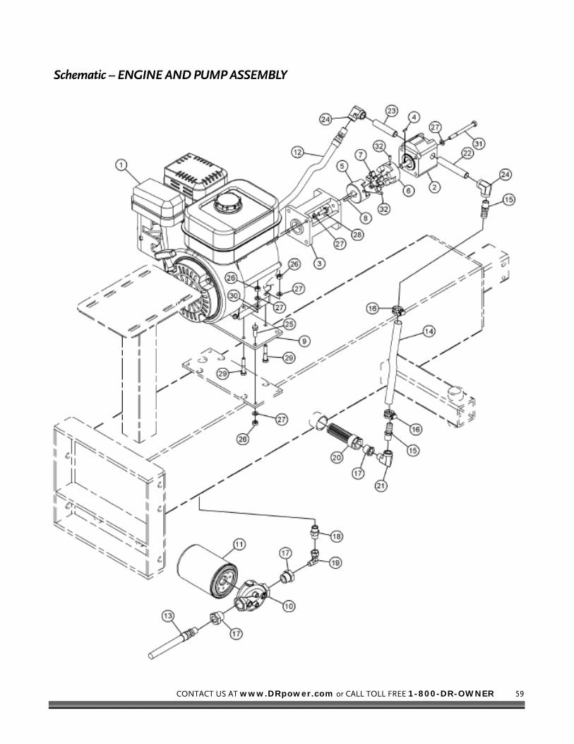
Schematic – ENGINE AND PUMP ASSEMBLY

60 DR® DIRT BOSS™ TOWABLE BACKHOE
Notes:

CONTACT US AT www.DRpower.com or CALL TOLL FREE 1-800-DR-OWNER 61
Notes:

62 DR® DIRT BOSS™ TOWABLE BACKHOE

DR® BACKHOE
2-Year Limited Warranty
Terms and Conditions
The DR® BACKHOE is warranted for two (2) years against defects in materials or workmanship when put to ordinary and normal consumer use; ninety (90) days for any other use.
For the purposes of all the above warranties, “ordinary and normal consumer use” refers to non-commercial residential use and does not include misuse, accidents or damage due to inadequate maintenance.
DR Power Equipment certifies that the DR® BACKHOE is fit for ordinary purposes for which a product of this type is used. DR Power Equipment however, limits the implied warranties of merchantability and fitness in duration to a period of two (2) years in consumer use, ninety (90) days for any other use.
The 2-Year Limited Warranty on the DR® BACKHOE starts on the date the machine ships from our factory. The 2-Year Limited Warranty is applicable only to the original owner.
The warranty holder is responsible for the performance of the required maintenance as defined by the manufacturer's
owner's manuals. The warranty holder is responsible for replacement of normally wearing parts such as the Filters,
Bucket Teeth and Wheels. Accessories to the machine are not covered by this warranty.
During the warranty period, the warranty holder is responsible for the machine transportation charges, if required.
During the warranty period, warranty parts will be shipped by standard method at no charge to the warranty holder.
Expedited shipping of warranty parts is the responsibility of the warranty holder.
SOME STATES DO NOT ALLOW LIMITATIONS ON THE LENGTH OF IMPLIED WARRANTIES, SO THE ABOVE
LIMITATIONS MAY NOT APPLY TO YOU.
DR Power Equipment shall not be liable under any circumstances for any incidental or consequential damages or expenses of any kind, including, but not limited to, cost of equipment rentals, loss of profit, or cost of hiring services to perform tasks normally performed by the DR® BACKHOE.
SOME STATES DO NOT ALLOW THE EXCLUSION OR LIMITATION OF INCIDENTAL OR CONSEQUENTIAL
DAMAGES, SO THE ABOVE LIMITATIONS MAY NOT APPLY TO YOU.
Customer Service Hotline DR Power Equipment’s objective is to have 100% satisfied customers. For that reason, we operate a 6-day-a-week Technical Service Department for our Owners. You can access a Representative by dialing our TOLL-FREE Hotline at 1-800-DR-OWNER (376-9637). The sole job of our well-trained and friendly folks is to ensure that you get any help you need in a timely fashion. They are there to answer all your questions including: (1) inquiries on any of the above warranties, (2) inquiries about replacement parts, or (3) your questions regarding service, maintenance and operation.
THIS WARRANTY GIVES YOU SPECIFIC LEGAL RIGHTS, AND YOU ALSO HAVE OTHER RIGHTS, WHICH VARY
FROM STATE TO STATE.
DR® Power Equipment
7 5 M E I G S R O A D , P . O . B O X 2 5 , V E R G E N N E S , V E R M O N T 0 5 4 9 1 1-800-DR-OWNER (376-9637) • www.DRpower.com ©2008 CHP, Inc. 247111
Daily Checklist for the DR DIRT BOSS TOWABLE BACKHOE
To help maintain your DR DIRT BOSS TOWABLE BACKHOE for optimum performance, we recommend you follow this checklist each time you use your Backhoe.
[ ] Check the engine oil level.
[ ] Check the general condition of the Backhoe, e.g.; nuts, bolts, welds etc.
[ ] Check Tire Pressure
[ ] Check Hydraulic Hoses and Connections
[ ] Lubricate Grease Fittings
CENTER THE BOOM. RETRACT THE BOOM, CROWD ARM AND BUCKET. INSTALL THE BOOM HITCH PINS AND LYNCH PINS TO LOCK THE BOOM IN PLACE. SHUT DOWN THE ENGINE, REMOVE THE SPARK PLUG WIRE AND WAIT 5 MINUTES BEFORE PERFORMING ANY MAINTENANCE PROCEDURE OR INSPECTION ON THE BACKHOE.
BE SURE THE AREA IS CLEAR OF UNDERGROUND OBSTRUCTIONS. CALL “811” BEFORE YOU DIG.