directout technologies - aspen media technologies® page 14 of 69 d.o.tec® andiamo remote - version...
TRANSCRIPT

D.O.TEC® ANDIAMO Remote
Version 1.2
Software Guide
DirectOut Technologies®

DirectOut Technologies®
page 2 of 69 © 2013 DirectOut GmbHD.O.TEC® ANDIAMO Remote - Version 1.2

DirectOut Technologies®
page 3 of 69© 2013 DirectOut GmbH D.O.TEC® ANDIAMO Remote - Version 1.2
Copyright Note
Copyright
All rights reserved. Permission to reprint or electronically reproduce any docu-ment or graphic in whole or in part for any reason is expressly prohibited, un-
less prior written consent is obtained from the DirectOut GmbH.
All trademarks and registered trademarks belong to their respective owners. It can-not be guaranteed that all product names, products, trademarks, requisitions, regulations,
guidelines, specifications and norms are free from trade mark rights of third parties.
All entries in this document have been thoroughly checked; how-ever no guarantee for correctness can be given.
DirectOut GmbH cannot be held responsible for any misleading or in-correct information provided throughout this manual.
DirectOut GmbH reserves the right to change specifications at any time without notice.
DirectOut Technologies® and D.O.TEC® are a registered trademarks of the DirectOut GmbH.
Windows® is a trademark of Microsoft Corporation,
© DirectOut GmbH, 2013

DirectOut Technologies®
page 4 of 69 © 2013 DirectOut GmbHD.O.TEC® ANDIAMO Remote - Version 1.2
This page is left blank intentionally.

DirectOut Technologies®
page 5 of 69© 2013 DirectOut GmbH D.O.TEC® ANDIAMO Remote - Version 1.2
Table of Contents
Table of contentsChapter 1 - IntroduCtIon 6
About this document 6Conventions 6
Chapter 2 - InstallatIon 7Requirements 7Installation procedure 7Repair / Remove Installation 10
Chapter 3 - ConneCtIon setup 13Remote Control 13Connecting the device 13Connecting multiple devices 17
Chapter 4a - andIaMo / andIaMo 2 19STATE view 19System Setup 20Delay Compensation 25Routing Matrix 26
Chapter 4b - andIaMo.Xt (2) / andIaMo.Xt srC (2) 29
STATE view 29System Setup 30Delay Compensation 36Routing Matrix 37
Chapter 4C - andIaMo.MC 39STATE view 39System Setup 40Delay Compensation 45Routing Matrix 46Levels - Gain control 48
Chapter 4d - andIaMo.aes (srC) 53STATE view 53System Setup 54Delay Compensation 60Routing Matrix 61
Chapter 5 - presets 63About Presets 63Storing Presets 63Reloading Presets 64Offline Mode 66
error Messages 68
IndeX 69

DirectOut Technologies®
page 6 of 69 © 2013 DirectOut GmbHD.O.TEC® ANDIAMO Remote - Version 1.2
Chapter 1 - Introduction
Chapter 1 - Introductionabout this documentEach device of the D.O.TEC® ANDIAMO Series can be remote controlled by a remote software application - ANDIAMO Remote - running on a Windows® PC.This document describes the installation and operation of the soft-ware. Information about the hardware and general operating in-structions are covered by the particular ‘Hardware Guide’.As the feature set and application differs between the particular de-vices Chapter 4 is split into different parts to meet the concerns of the particular devices.
ConventionsThe following symbols are used to draw your attention to:
tips – indicate useful tips and short cuts.
notes – are used for important points of clarification or cross refer-ences.
Warning Warnings – alert you when an action should always be observed.
XT / XT SRC Version
ANDIAMO Version
MC Version
AES Version
Chapters that are split are marked with individual side bars:
ANDIAMO.MC
ANDIAMO.AES
ANDIAMO.XT and ANDIAMO.XT SRCANDIAMO 2.XT and ANDIAMO 2.XT SRC
ANDIAMO and ANDIAMO 2

DirectOut Technologies®
page 7 of 69© 2013 DirectOut GmbH D.O.TEC® ANDIAMO Remote - Version 1.2
Chapter 2 - Installation
Chapter 2 - InstallationrequirementsSupported OS versions are Windows® XP, Vista, 7 and 8.
Installation procedure1. Download the application
Link: http://www.directout.eu/de/support/downloads/index.html
2. Unpack the zip archive into a temp directory.
3. Launch the installer: setup_andiamo_remote.exe
4. A wizard will guide you through all necessary steps.

DirectOut Technologies®
page 8 of 69 © 2013 DirectOut GmbHD.O.TEC® ANDIAMO Remote - Version 1.2
Chapter 2 - Installation
5. Accept the license agreement to proceed.
6. Specify the destination for the installation.

DirectOut Technologies®
page 9 of 69© 2013 DirectOut GmbH D.O.TEC® ANDIAMO Remote - Version 1.2
Chapter 2 - Installation
7. Check your settings and click <Install> to proceed. The instal-lation process will take a moment.
8. After successful intallation you will be prompted to fi nnish the wizard.

DirectOut Technologies®
page 10 of 69 © 2013 DirectOut GmbHD.O.TEC® ANDIAMO Remote - Version 1.2
Chapter 2 - Installation
1. Once the application is already installed on the system and the installer is launched again it will offer a repair, modifi y or removal of the installation. Select and click <Next> to proceed.
2. Confi rm your selection (e.g. Remove).
repair / remove Installation

DirectOut Technologies®
page 11 of 69© 2013 DirectOut GmbH D.O.TEC® ANDIAMO Remote - Version 1.2
Chapter 2 - Installation
3. After successful operation you will be prompted to fi nnish the wizard.

DirectOut Technologies®
page 12 of 69 © 2013 DirectOut GmbHD.O.TEC® ANDIAMO Remote - Version 1.2
Chapter 2 - Installation
This page is left blank intentionally.

DirectOut Technologies®
page 13 of 69© 2013 DirectOut GmbH D.O.TEC® ANDIAMO Remote - Version 1.2
Chapter 3 - Connection Setup
Chapter 3 - Connection setupremote ControlThe software may control the device using four different methods:
a) Serial control via USB
b) Serial over MADI (embedded RS-232 data)
c) MIDI over MADI (embedded MIDI data)
d) USB over Ethernet - DO.Net
All settings are stored inside the device. An offl ine mode allows to prepare settings and to store them to fi le for later use.
Remote control requires :• fi rmware version 1.5 or higher for ANDIAMO.MC
• fi rmware version 2.5 or higher for all other ANDIAMO devices
Connecting the deviceTo connect with the device the method and the port must be se-lected.
Method a) and b) both use a COM port of the operating system.Method a) requires:
• USB connection to the device
• installed D.O.TEC® USB Serial driver

DirectOut Technologies®
page 14 of 69 © 2013 DirectOut GmbHD.O.TEC® ANDIAMO Remote - Version 1.2
Chapter 3 - Connection Setup
Method b) requires:
• installed COM port on the computer
• an embedder / de-embedder
Suitable embedder devices:
• D.O.TEC® PRODUCER.COM
• D.O.TEC® EXBOX.MIDICOM
• D.O.TEC® EXBOX.AES
• D.O.TEC® M1.k2
• D.O.TEC® MA2CHBOX
• D.O.TEC® MA2CHBOX.XT
To connect:
• Select the COM port
• Click ‘CONNECT’
When using method b) make sure that the baud rate of the used embedder is set to 115.200 baud.
To ensure proper operation using embedded serial data a bit trans-parent bidirectional link of the MADI signal is required.
The driver and the installation instructions are available atwww.directout.eu.
To connect:
• Select the COM port
• Click ‘CONNECT’

DirectOut Technologies®
page 15 of 69© 2013 DirectOut GmbH D.O.TEC® ANDIAMO Remote - Version 1.2
Chapter 3 - Connection Setup
Suitable embedder devices:
• D.O.TEC® PRODUCER.COM
• D.O.TEC® EXBOX.MIDICOM
• D.O.TEC® M1.k2
• MADI card with built in embedder / de-embedder
Method c) requires:
• a MIDI device to be installed on the computer
• an embedder / de-embedder
To connect:
• Select MIDI I/O
• Enable MIDI I/O
• Click Connect
To ensure proper operation using embedded MIDI data a bit trans-parent bidirectional link of the MADI signal is required.

DirectOut Technologies®
page 16 of 69 © 2013 DirectOut GmbHD.O.TEC® ANDIAMO Remote - Version 1.2
Chapter 3 - Connection Setup
Method d) requires:
• Raspberry Pi with ethernet port
• SD Card with at least 2 GB capacity
• Network
The Raspberry Pi is connected with the ANDIAMO device via USB. The ethernet connection with the network allows to remote control the ANDIAMO from anywhere within the network. The DO.Net daemon translates serial data between the network and the local USB port of an ANDIAMO device.
To connect:
• Enable Network
• Click Connect
This connection method requires additional hardware that is not provided by DirectOut. See document ‘Info - DO.Net” for further in-formation: http://www.directout.eu/de/support/downloads/index.html

DirectOut Technologies®
page 17 of 69© 2013 DirectOut GmbH D.O.TEC® ANDIAMO Remote - Version 1.2
Chapter 3 - Connection Setup
Connecting multiple devicesIt is possible to remote control multiple devices by the remote ap-plication.
Go to ‘Command - Select Device’. All detected devices are listed by a pulldown menu.
Examples:
The menu becomes active once a connection is established. The adjusted COM port or MIDI port is used for detection. All further devices are detected by embedded control data in the MADI signal.
RS-232 data is (de-)embedded by the fi rst ANDIAMO into the MADI signal. The MADI ring between the two devices ensures the bidirec-tional communication. See „Embedding serial data“ on page 18.
Embedded MIDI data controls both ANDIAMOs. The MADI ring be-tween the three devices ensures the bidirectional communication.
PC ANDIAMO device #1*
ANDIAMO device #2
RS-232 (via USB)
MADI + RS-232
MADI + RS-232
*) USB embedder active
COM #xx
PC ANDIAMO device #1
ANDIAMO device #2
MADI + MIDI
MADI + MIDI
MADI + MIDI

DirectOut Technologies®
page 18 of 69 © 2013 DirectOut GmbHD.O.TEC® ANDIAMO Remote - Version 1.2
Chapter 3 - Connection Setup
It is also possible to connect more than one device via USB locally and to open several instances of ANDIAMO Remote.
PC ANDIAMO device #1
ANDIAMO device #2
RS-232 (via USB)
RS-232 (via USB)COM #xx
COM #yy
embedding serial dataA built in USB Embedder can be used to process remote control data from the local USB port through the MADI line.The remote control data (RS-232) is embedded into the MADI out-put signal of the device and deembedded from the MADI input sig-nal of the device.The USB Embedder can be activated in the particular settings page of the ANDIAMO Remote.It is deactivated by default after switch on of the device.The built in USB Embedder allows for remote control of further de-vices over large distances without the need of additional hardware.

DirectOut Technologies®
page 19 of 69© 2013 DirectOut GmbH D.O.TEC® ANDIAMO Remote - Version 1.2
Chapter 4a - ANDIAMO / ANDIAMO 2A
ND
IAM
O V
ersion
Click ‘Settings’ to open the system setup dialog.Click ‘MATRIX’ to toggle the MATRIX view.Point to ‘CONNECTED’ and click ‘DISCONNECT’ to close the con-nection.
Chapter 4a - andIaMo / andIaMo 2state viewThe state view monitors the system state and informs about the system settings. The bottom bar monitors the connection state with the device.
Depending on the connected device the view may differ.

DirectOut Technologies®
page 20 of 69 © 2013 DirectOut GmbHD.O.TEC® ANDIAMO Remote - Version 1.2
Chapter 4a - ANDIAMO / ANDIAMO 2A
ND
IAM
O V
ersi
on
system setupMost system settings can be adjusted either locally or via the remote application. The settings are stored inside the device. Additionally presets can be stored to a fi le for later use. A few settings can be accessed via the remote application only:
• confi guration of the system fan control
• redundancy mode (only devices with two MADI I/Os)
• routing matrix
• (de-)activation of built-in USB Embedder
To adust the settings either click the radial buttons, checkboxes or use the pull down menus.Click ‘OK’ to close the dialog applying all changes.Click ‘Cancel’ to close the dialog discarding all changes.Click ‘Apply’ to transmit all changes without closing the dialog.
Clock sourceThe system clock can be set to one of three possible clock sources. The termination of the word clock input is switchable.
WCK clock source set to word clock input
MadI clock source set to (selected) MADI input
Int clock source set to internal clock generator
DirectOut Technologies®
page 21 of 69© 2013 DirectOut GmbH D.O.TEC® ANDIAMO Remote - Version 1.2
Chapter 4a - ANDIAMO / ANDIAMO 2A
ND
IAM
O V
ersion
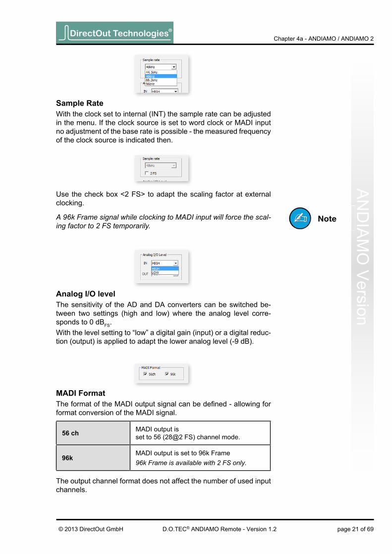
sample rateWith the clock set to internal (INT) the sample rate can be adjusted in the menu. If the clock source is set to word clock or MADI input no adjustment of the base rate is possible - the measured frequency of the clock source is indicated then.
analog I/o levelThe sensitivity of the AD and DA converters can be switched be-tween two settings (high and low) where the analog level corre-sponds to 0 dBFS.With the level setting to “low” a digital gain (input) or a digital reduc-tion (output) is applied to adapt the lower analog level (-9 dB).
MadI FormatThe format of the MADI output signal can be defi ned - allowing for format conversion of the MADI signal.
56 ch MADI output is set to 56 (28@2 FS) channel mode.
96kMADI output is set to 96k Frame96k Frame is available with 2 FS only.
The output channel format does not affect the number of used input channels.
Use the check box <2 FS> to adapt the scaling factor at external clocking.
A 96k Frame signal while clocking to MADI input will force the scal-ing factor to 2 FS temporarily.
DirectOut Technologies®
page 22 of 69 © 2013 DirectOut GmbHD.O.TEC® ANDIAMO Remote - Version 1.2
Chapter 4a - ANDIAMO / ANDIAMO 2A
ND
IAM
O V
ersi
on
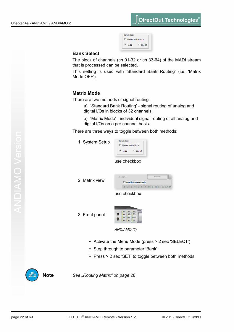
bank selectThe block of channels (ch 01-32 or ch 33-64) of the MADI stream that is processed can be selected.This setting is used with ‘Standard Bank Routing’ (i.e. ‘Matrix Mode OFF’).
Matrix ModeThere are two methods of signal routing:
a) ‘Standard Bank Routing’ - signal routing of analog and digital I/Os in blocks of 32 channels.
b) ‘Matrix Mode’ - individual signal routing of all analog and digital I/Os on a per channel basis.
There are three ways to toggle between both methods:
1. System Setup
2. Matrix view
3. Front panel
• Activate the Menu Mode (press > 2 sec ‘SELECT’)
• Step through to parameter ‘Bank’
• Press > 2 sec ‘SET’ to toggle between both methods
See „Routing Matrix“ on page 26
use checkbox
use checkbox
ANDIAMO (2)
DirectOut Technologies®
page 23 of 69© 2013 DirectOut GmbH D.O.TEC® ANDIAMO Remote - Version 1.2
Chapter 4a - ANDIAMO / ANDIAMO 2A
ND
IAM
O V
ersion
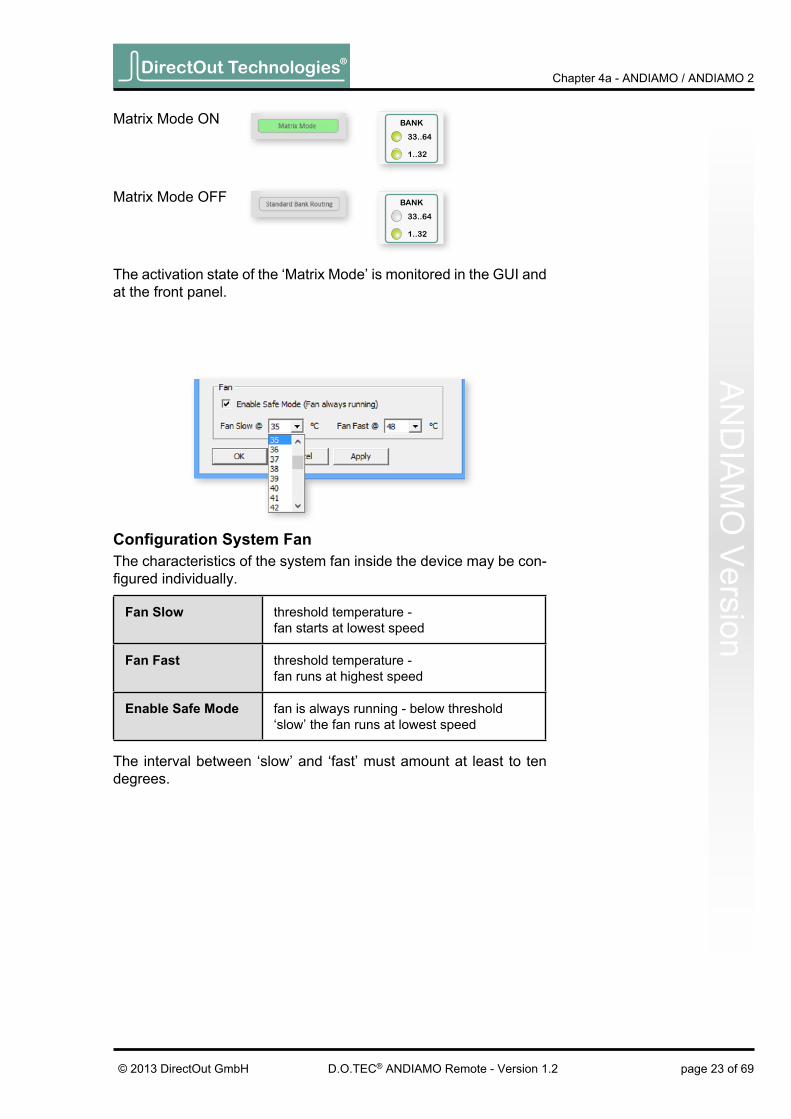
Confi guration System FanThe characteristics of the system fan inside the device may be con-fi gured individually.
Fan slow threshold temperature - fan starts at lowest speed
Fan Fast threshold temperature - fan runs at highest speed
enable safe Mode fan is always running - below threshold ‘slow’ the fan runs at lowest speed
The interval between ‘slow’ and ‘fast’ must amount at least to ten degrees.
The activation state of the ‘Matrix Mode’ is monitored in the GUI and at the front panel.
Matrix Mode ON
Matrix Mode OFF

DirectOut Technologies®
page 24 of 69 © 2013 DirectOut GmbHD.O.TEC® ANDIAMO Remote - Version 1.2
Chapter 4a - ANDIAMO / ANDIAMO 2A
ND
IAM
O V
ersi
on redundancy ModeDevices with two MADI I/Os provide input redundancy.Redundancy modes:
1. Standard - automatic port selection
2. Priority - priority input port selected
3. Off - forced input port selection
Mode description switch over revert
Standard
The fi rst MADI input that detects a valid signal will be used. If this input fails, the device will switch to the other input (if it is locked).
yes no
Priority
The defi ned priority port is always selected automatically if a valid signal is detected. Selection will revert to the priority port, after switch over (due to signal loss).
yes yes
OffAutomatic selection is overriden by forcing the input selection to a specifi c MADI input port.
no no
Pulldown menu with fi ve options. ‘Redundancy active’ is the default setting (‘Standard’).
The LED of the forced input port is framed by a blue rectangle.
The MADI output ports work in parallel.
The redundancy setting is always set to ‘Standard’ at switch on of the device.

DirectOut Technologies®
page 25 of 69© 2013 DirectOut GmbH D.O.TEC® ANDIAMO Remote - Version 1.2
Chapter 4a - ANDIAMO / ANDIAMO 2A
ND
IAM
O V
ersion
The USB embedder is deactivated by default after switch on of the device. See „Embedding serial data“ on page 18.
usb embedderThe USB Embedder processes remote control data between the local USB port and the MADI I/O. It can be used to control multiple devices.
A green label indicates activated delay compensation.
delay CompensationDelay compensation becomes active, if a device of the ANDIAMO series ‘sees’ another ANDIAMO device at its input. The ‘second’ device will switch to ID 02 automatically.
1. STATE view:
Indication of ID 2: LED <bank selection> heartbeat.
Consult the ‘Hardware Guide’ for more information about delay compensation.
2. Front panel:
DirectOut Technologies®
page 26 of 69 © 2013 DirectOut GmbHD.O.TEC® ANDIAMO Remote - Version 1.2
Chapter 4a - ANDIAMO / ANDIAMO 2A
ND
IAM
O V
ersi
on
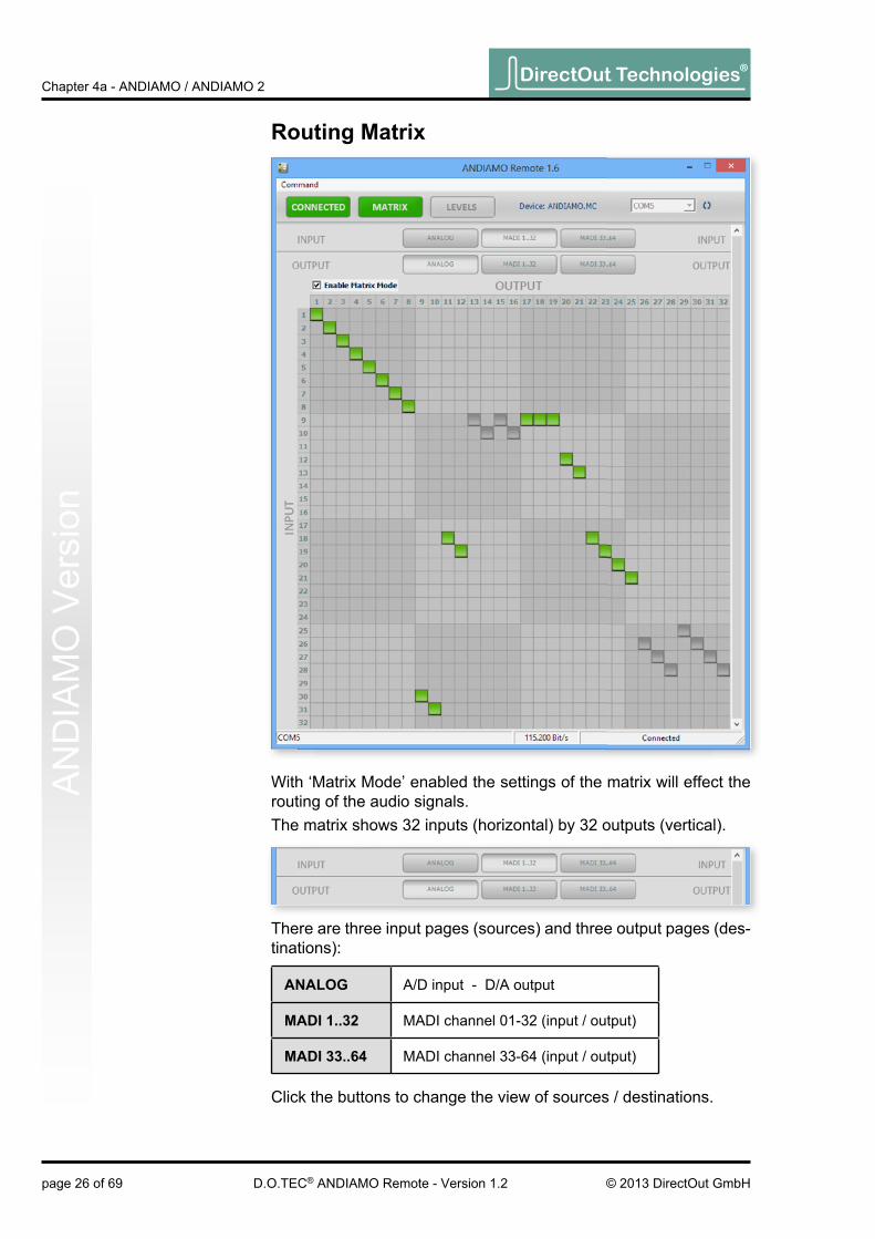
routing Matrix
With ‘Matrix Mode’ enabled the settings of the matrix will effect the routing of the audio signals.The matrix shows 32 inputs (horizontal) by 32 outputs (vertical).
There are three input pages (sources) and three output pages (des-tinations):
analog A/D input - D/A output
MadI 1..32 MADI channel 01-32 (input / output)
MadI 33..64 MADI channel 33-64 (input / output)
Click the buttons to change the view of sources / destinations.

DirectOut Technologies®
page 27 of 69© 2013 DirectOut GmbH D.O.TEC® ANDIAMO Remote - Version 1.2
Chapter 4a - ANDIAMO / ANDIAMO 2A
ND
IAM
O V
ersionsetting / deleting crosspoints
• move the cursor to the desired position - a small green square and transparent bars point the active position
• click into the square to set / delete the crosspoint
To set more than one crosspoint you may click and hold the left mouse button and move the cursor. The pointed crosspoints will be set upon release of the mouse button.
crosspoint - output is set on the selected input page.
crosspoint - output is set on a non-se-lected input page.

DirectOut Technologies®
page 28 of 69 © 2013 DirectOut GmbHD.O.TEC® ANDIAMO Remote - Version 1.2
Chapter 4a - ANDIAMO / ANDIAMO 2
This page is left blank intentionally.
DirectOut Technologies®
page 29 of 69© 2013 DirectOut GmbH D.O.TEC® ANDIAMO Remote - Version 1.2
Chapter 4b - ANDIAMO.XT (2) / ANDIAMO.XT SRC (2)X
T / XT S
RC
Version
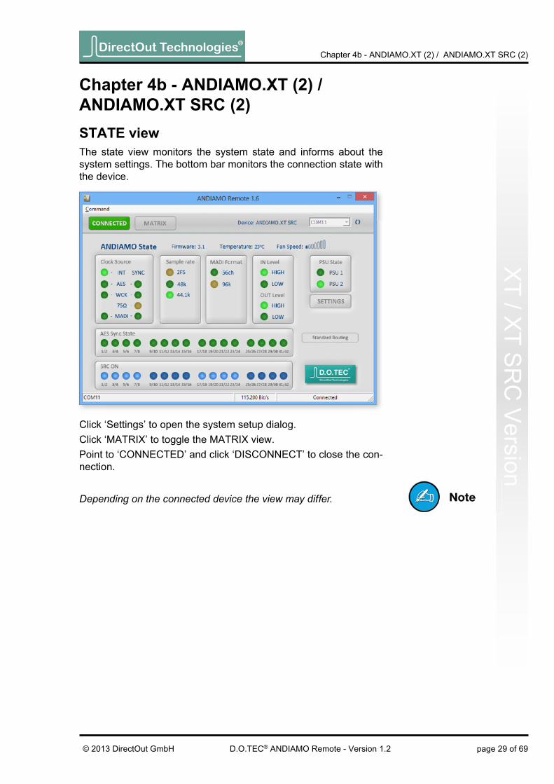
Click ‘Settings’ to open the system setup dialog.Click ‘MATRIX’ to toggle the MATRIX view.Point to ‘CONNECTED’ and click ‘DISCONNECT’ to close the con-nection.
Chapter 4b - andIaMo.Xt (2) / andIaMo.Xt srC (2)state viewThe state view monitors the system state and informs about the system settings. The bottom bar monitors the connection state with the device.
Depending on the connected device the view may differ.

DirectOut Technologies®
page 30 of 69 © 2013 DirectOut GmbHD.O.TEC® ANDIAMO Remote - Version 1.2
Chapter 4b - ANDIAMO.XT (2) / ANDIAMO.XT SRC (2)X
T / X
T S
RC
Ver
sion
system setupMost system settings can be adjusted either locally or via the remote application. The settings are stored inside the device. Additionally presets can be stored to a fi le for later use. A few settings can be accessed via the remote application only:
• confi guration of the system fan control
• redundancy mode (only devices with two MADI I/Os)
• signal routing (‘Matrix Mode’)
• user bit transparency for AES inputs
• (de-)activation of built-in USB Embedder
To adust the settings either click the radial buttons, checkboxes or use the pull down menus.Click ‘OK’ to close the dialog applying all changes.Click ‘Cancel’ to close the dialog discarding all changes.Click ‘Apply’ to transmit all changes without closing the dialog.

DirectOut Technologies®
page 31 of 69© 2013 DirectOut GmbH D.O.TEC® ANDIAMO Remote - Version 1.2
Chapter 4b - ANDIAMO.XT (2) / ANDIAMO.XT SRC (2)X
T / XT S
RC
Version
Clock sourceThe system clock can be set to one of four possible clock sources. The termination of the word clock input is switchable.
Int clock source set to internal clock generator
aes clock source set to AES input
WCK clock source set to word clock input
MadI clock source set to (selected) MADI input
If the clock source is set to AES the selection of the AES port as clock source uses the following pattern in ascending order:lowest input port receiving a valid AES signal
sample rateWith the clock set to internal (INT) the sample rate can be adjusted in the menu. If the clock source is set to word clock or AES or MADI input no adjustment of the base rate is possible - the measured fre-quency of the clock source is indicated then.
Use the check box <2 FS> to adapt the scaling factor at external clocking.
A 96k Frame signal while clocking to MADI input will force the scal-ing factor to 2 FS temporarily.
sample rate ConversionThe sample rate converters for the AES inputs are switchable in groups of eight channels (SRC Version).The activation state is indicated in the STATE view.

DirectOut Technologies®
page 32 of 69 © 2013 DirectOut GmbHD.O.TEC® ANDIAMO Remote - Version 1.2
Chapter 4b - ANDIAMO.XT (2) / ANDIAMO.XT SRC (2)X
T / X
T S
RC
Ver
sion
analog I/o levelThe sensitivity of the AD and DA converters can be switched be-tween two settings (high and low) where the analog level corre-sponds to 0 dBFS.With the level setting to “low” a digital gain (input) or a digital reduc-tion (output) is applied to adapt the lower analog level (-9 dB).
MadI FormatThe format of the MADI output signal can be defi ned - allowing for format conversion of the MADI signal.
56 ch MADI output is set to 56 (28@2 FS) channel mode.
96kMADI output is set to 96k Frame96k Frame is available with 2 FS only.
The output channel format does not affect the number of used input channels.
standard bank routingThe input signals can be routed in blocks (e.g. A/D to MADI 01..32) or on a per channel basis - see „Matrix Mode“ on page 33.Use the pull-down menus to defi ne the input source for the particu-lar output.<Fallback>AES input is used at fi rst. In case the AES input fails (no lock) the device switches to analog input for the respective channel pair only.Only available for MADI output (<01..32 OUT> or <33..64 OUT>).

DirectOut Technologies®
page 33 of 69© 2013 DirectOut GmbH D.O.TEC® ANDIAMO Remote - Version 1.2
Chapter 4b - ANDIAMO.XT (2) / ANDIAMO.XT SRC (2)X
T / XT S
RC
Version
Matrix ModeThere are two methods of signal routing:
a) ‘Standard Bank Routing’ - signal routing of analog and digital I/Os in blocks of 32 channels.
b) ‘Matrix Mode’ - individual signal routing of all analog and digital I/Os on a per channel basis.
There are three ways to toggle between both methods:
1. System Setup
2. Matrix view
3. Front panel
• activate the Menu Mode for Signal Routing (press > 2 sec ‘SELECT’)
• Press > 2 sec ‘SET’ to toggle between both methods
use checkbox
use checkbox
XT & XT SRC
See „Routing Matrix“ on page 37
The activation state of the ‘Matrix Mode’ is monitored in the GUI and at the front panel.
Matrix Mode ON
Matrix Mode OFF
DirectOut Technologies®
page 34 of 69 © 2013 DirectOut GmbHD.O.TEC® ANDIAMO Remote - Version 1.2
Chapter 4b - ANDIAMO.XT (2) / ANDIAMO.XT SRC (2)X
T / X
T S
RC
Ver
sion
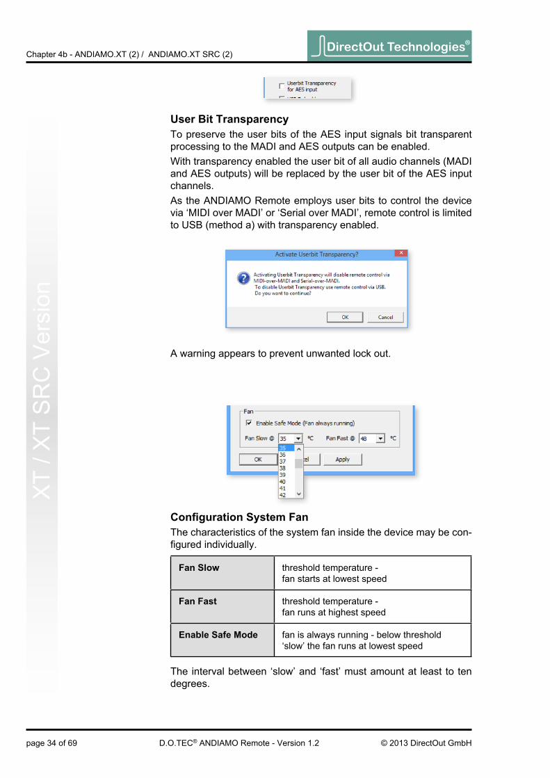
user bit transparencyTo preserve the user bits of the AES input signals bit transparent processing to the MADI and AES outputs can be enabled.With transparency enabled the user bit of all audio channels (MADI and AES outputs) will be replaced by the user bit of the AES input channels.As the ANDIAMO Remote employs user bits to control the device via ‘MIDI over MADI’ or ‘Serial over MADI’, remote control is limited to USB (method a) with transparency enabled.
A warning appears to prevent unwanted lock out.
Confi guration System FanThe characteristics of the system fan inside the device may be con-fi gured individually.
Fan slow threshold temperature - fan starts at lowest speed
Fan Fast threshold temperature - fan runs at highest speed
enable safe Mode fan is always running - below threshold ‘slow’ the fan runs at lowest speed
The interval between ‘slow’ and ‘fast’ must amount at least to ten degrees.

DirectOut Technologies®
page 35 of 69© 2013 DirectOut GmbH D.O.TEC® ANDIAMO Remote - Version 1.2
Chapter 4b - ANDIAMO.XT (2) / ANDIAMO.XT SRC (2)X
T / XT S
RC
Version
redundancy ModeDevices with two MADI I/Os provide input redundancy.Redundancy modes:
1. Standard - automatic port selection
2. Priority - priority input port selected
3. Off - forced input port selection
Mode description switch over revert
Standard
The fi rst MADI input that detects a valid signal will be used. If this input fails, the device will switch to the other input (if it is locked).
yes no
Priority
The defi ned priority port is always selected automatically if a valid signal is detected. Selection will revert to the priority port, after switch over (due to signal loss).
yes yes
OffAutomatic selection is overriden by forcing the input selection to a specifi c MADI input port.
no no
Pulldown menu with fi ve options. ‘Redundancy active’ is the default setting (‘Standard’).
The LED of the forced input port is framed by a blue rectangle.
The MADI output ports work in parallel.
The redundancy setting is always set to ‘Standard’ at switch on of the device.

DirectOut Technologies®
page 36 of 69 © 2013 DirectOut GmbHD.O.TEC® ANDIAMO Remote - Version 1.2
Chapter 4b - ANDIAMO.XT (2) / ANDIAMO.XT SRC (2)X
T / X
T S
RC
Ver
sion
A green label indicates activated delay compensation.
delay CompensationDelay compensation becomes active, if a device of the ANDIAMO series ‘sees’ another ANDIAMO device at its input. The ‘second’ device will switch to ID 02 automatically.
STATE view:
Consult the ‘Hardware Guide’ for more information about delay compensation.
The USB embedder is deactivated by default after switch on of the device. See „Embedding serial data“ on page 18.
usb embedderThe USB Embedder processes remote control data between the local USB port and the MADI I/O. It can be used to control multiple devices.

DirectOut Technologies®
page 37 of 69© 2013 DirectOut GmbH D.O.TEC® ANDIAMO Remote - Version 1.2
Chapter 4b - ANDIAMO.XT (2) / ANDIAMO.XT SRC (2)X
T / XT S
RC
Version
routing Matrix
With ‘Matrix Mode’ enabled the settings of the matrix will effect the routing of the audio signals.The matrix shows 32 inputs (horizontal) by 32 outputs (vertical).
There are four input pages (sources) and four output pages (desti-nations):
analog A/D input - D/A output
MadI 1..32 MADI channel 01-32 (input / output)
MadI 33..64 MADI channel 33-64 (input / output)
aes AES (input / output)
Click the buttons to change the view of sources / destinations.

DirectOut Technologies®
page 38 of 69 © 2013 DirectOut GmbHD.O.TEC® ANDIAMO Remote - Version 1.2
Chapter 4b - ANDIAMO.XT (2) / ANDIAMO.XT SRC (2)X
T / X
T S
RC
Ver
sion
setting / deleting crosspoints• move the cursor to the desired position - a small green square
and transparent bars point the active position
• click into the square to set / delete the crosspoint
To set more than one crosspoint you may click and hold the left mouse button and move the cursor. The pointed crosspoints will be set upon release of the mouse button.
crosspoint - output is set on the selected input page.
crosspoint - output is set on a non-se-lected input page.

DirectOut Technologies®
page 39 of 69© 2013 DirectOut GmbH D.O.TEC® ANDIAMO Remote - Version 1.2
Chapter 4c - ANDIAMO.MCM
C V
ersionClick ‘Settings’ to open the system setup dialog.Click ‘MATRIX’ to toggle the MATRIX view.Click ‘LEVELS’ to toggle the LEVELS viewPoint to ‘CONNECTED’ and click ‘DISCONNECT’ to close the con-nection.
Chapter 4c - andIaMo.MCstate viewThe STATE view monitors the system state and informs about the system settings. The bottom bar monitors the connection state with the device.
Depending on the connected device the view may differ.

DirectOut Technologies®
page 40 of 69 © 2013 DirectOut GmbHD.O.TEC® ANDIAMO Remote - Version 1.2
Chapter 4c - ANDIAMO.MCM
C V
ersi
on
system setupMost system settings can be adjusted either locally or via the remote application. The settings are stored inside the device. Additionally presets can be stored to a fi le for later use. A few settings can be accessed via the remote application only:
• confi guration of the system fan control
• redundancy mode
• routing matrix
• GPO trigger
• (de-)activation of built-in USB Embedder
• display dark function
To adust the settings either click the radial buttons, checkboxes or use the pull down menus.Click ‘OK’ to close the dialog applying all changes.Click ‘Cancel’ to close the dialog discarding all changes.Click ‘Apply’ to transmit all changes without closing the dialog.
Clock sourceThe system clock can be set to one of three possible clock sources. The termination of the word clock input is switchable.
WCK clock source set to word clock input
MadI clock source set to (selected) MADI input
Int clock source set to internal clock generator

DirectOut Technologies®
page 41 of 69© 2013 DirectOut GmbH D.O.TEC® ANDIAMO Remote - Version 1.2
Chapter 4c - ANDIAMO.MCM
C V
ersion
sample rateWith the clock set to internal (INT) the sample rate can be adjusted in the menu. If the clock source is set to word clock or MADI input no adjustment of the base rate is possible - the measured frequency of the clock source is indicated then.
analog output levelThe sensitivity of the DA converters can be switched between two settings (high and low) where the analog level corresponds to 0 dBFS.With the level setting to “low” a digital reduction (output) is applied to adapt the lower analog level (-9 dB).The input sensitivity (AD) is adjusted on a per channel basis in the LEVELS section - see „Levels - Gain control“ on page 48.
MadI FormatThe format of the MADI output signal can be defi ned - allowing for format conversion of the MADI signal.
56 ch MADI output is set to 56 (28@2 FS) channel mode.
96kMADI output is set to 96k Frame96k Frame is available with 2 FS only.
The output channel format does not affect the number of used input channels.
Use the check box <2 FS> to adapt the scaling factor at external clocking.
A 96k Frame signal while clocking to MADI input will force the scal-ing factor to 2 FS temporarily.

DirectOut Technologies®
page 42 of 69 © 2013 DirectOut GmbHD.O.TEC® ANDIAMO Remote - Version 1.2
Chapter 4c - ANDIAMO.MCM
C V
ersi
on
bank selectThe block of channels (ch 01-32 or ch 33-64) of the MADI stream that is processed can be selected.This setting is used with ‘Standard Bank Routing’ (i.e. ‘Matrix Mode OFF’).
Matrix ModeThere are two methods of signal routing:
a) ‘Standard Bank Routing’ - signal routing of analog and digital I/Os as a whole.
b) ‘Matrix Mode’ - individual signal routing of all analog and digital I/Os on a per channel basis.
There are three ways to toggle between both methods:
1. System Setup
2. Matrix view
3. Front panel
• Activate the Menu Mode (press > 2 sec ‘SELECT’)
• Step through to parameter ‘Bank’
• Press > 2 sec ‘SET’ to toggle between both methods
See „Routing Matrix“ on page 46.
use checkbox
use checkbox
ANDIAMO.MC

DirectOut Technologies®
page 43 of 69© 2013 DirectOut GmbH D.O.TEC® ANDIAMO Remote - Version 1.2
Chapter 4c - ANDIAMO.MCM
C V
ersionConfi guration System FanThe characteristics of the system fan inside the device may be con-fi gured individually.
Fan slow threshold temperature - fan starts at lowest speed
Fan Fast threshold temperature - fan runs at highest speed
enable safe Mode fan is always running - below threshold ‘slow’ the fan runs at lowest speed
The interval between ‘slow’ and ‘fast’ must amount at least to ten degrees.
The activation state of the ‘Matrix Mode’ is monitored in the GUI and at the front panel.
Matrix Mode ON
Matrix Mode OFF

DirectOut Technologies®
page 44 of 69 © 2013 DirectOut GmbHD.O.TEC® ANDIAMO Remote - Version 1.2
Chapter 4c - ANDIAMO.MCM
C V
ersi
on redundancy ModeDevices with two MADI I/Os provide input redundancy.Redundancy modes:
1. Standard - automatic port selection
2. Priority - priority input port selected
3. Off - forced input port selection
Mode description switch over revert
Standard
The fi rst MADI input that detects a valid signal will be used. If this input fails, the device will switch to the other input (if it is locked).
yes no
Priority
The defi ned priority port is always selected automatically if a valid signal is detected. Selection will revert to the priority port, after switch over (due to signal loss).
yes yes
OffAutomatic selection is overriden by forcing the input selection to a specifi c MADI input port.
no no
Pulldown menu with fi ve options. ‘Redundancy active’ is the default setting (‘Standard’).
The LED of the forced input port is framed by a blue rectangle.
The MADI output ports work in parallel.
The redundancy setting is always set to ‘Standard’ at switch on of the device.

DirectOut Technologies®
page 45 of 69© 2013 DirectOut GmbH D.O.TEC® ANDIAMO Remote - Version 1.2
Chapter 4c - ANDIAMO.MCM
C V
ersion
A green label indicates activated delay compensation.
delay CompensationDelay compensation becomes active, if a device of the ANDIAMO series ‘sees’ another ANDIAMO device at its input. The ‘second’ device will switch to ID 02 automatically.
STATE view:
Consult the ‘Hardware Guide’ for more information about delay compensation.
The USB embedder is deactivated by default after switch on of the device. See „Embedding serial data“ on page 18.
usb embedderThe USB Embedder processes remote control data between the local USB port and the MADI I/O. It can be used to control multiple devices.
display darkThe monitoring of the LEDs (except the PSU LED) at the front panel of the device can be switched off after a timeout of a few seconds. If activated the device can be operated at sensitive environments without attracting unwanted attention.

DirectOut Technologies®
page 46 of 69 © 2013 DirectOut GmbHD.O.TEC® ANDIAMO Remote - Version 1.2
Chapter 4c - ANDIAMO.MCM
C V
ersi
on
routing Matrix
With ‘Matrix Mode’ enabled the settings of the matrix will effect the routing of the audio signals.The matrix shows 32 inputs (horizontal) by 32 outputs (vertical).
There are three input pages (sources) and three output pages (des-tinations):
analog A/D input - D/A output
MadI 1..32 MADI channel 01-32 (input / output)
MadI 33..64 MADI channel 33-64 (input / output)
Click the buttons to change the view of sources / destinations.

DirectOut Technologies®
page 47 of 69© 2013 DirectOut GmbH D.O.TEC® ANDIAMO Remote - Version 1.2
Chapter 4c - ANDIAMO.MCM
C V
ersionsetting / deleting crosspoints
• move the cursor to the desired position - a small green square and transparent bars point the active position
• click into the square to set / delete the crosspoint
To set more than one crosspoint you may click and hold the left mouse button and move the cursor. The pointed crosspoints will be set upon release of the mouse button.
crosspoint - output is set on the selected input page.
crosspoint - output is set on a non-se-lected input page.

DirectOut Technologies®
page 48 of 69 © 2013 DirectOut GmbHD.O.TEC® ANDIAMO Remote - Version 1.2
Chapter 4c - ANDIAMO.MCM
C V
ersi
on
levels - gain controlThe LEVELS view is used for input sensitivity control and level mon-itoring of the 32 analog input channels.
Meter inputs level meter of all analog inputs
Fader inputs setting of input sensitivity (gain)
Channel control control of phantom power (P48) and 30 dB pad (PAD)
GPO trigger triggering of GPO and control of polarity
Display Peak Hold indication of highest signal level is hold
Meter inputs
Fader inputs
Channel control
GPO trigger
Display Peak Hold

DirectOut Technologies®
page 49 of 69© 2013 DirectOut GmbH D.O.TEC® ANDIAMO Remote - Version 1.2
Chapter 4c - ANDIAMO.MCM
C V
ersionMeter inputs
display peak hold
Display:
• Bargraphs indicate digital level of the input signal correspond-ing the adjusted input sensitivity (gain).
• Numerical metering of signal level and ‘over’.
• Numerical label of channel
Functions:
• To reset the peak hold click into the bargraph of a channel
• To reset all input level meters double-click in the bargraph of any channel.
Display:
• activation state of display peak hold function
Functions:
• Click to rectangle to toggle the state of the peak hold switch
legend
display peak hold is inactive
display peak hold is active

DirectOut Technologies®
page 50 of 69 © 2013 DirectOut GmbHD.O.TEC® ANDIAMO Remote - Version 1.2
Chapter 4c - ANDIAMO.MCM
C V
ersi
onFader inputs
Display:
• Fader monitoring input sensitivity of channel
• Fader - horizontal lines @ -6 / -18 / -30 / -42 / -55 dBu (Pad inactive)
• Numerical monitoring of input sensitivity
• Numerical label of channel
Functions:
• Move fader element or use arrow keys (up / down) to alter input sensitivity.
• Double-click fader or hit ‘ENTER’ to toggle input sensitivity between actual and previous value.
• Use arrow keys (left / right) to navigate between channels.
• Hit ‘0’ key at numerical block to set the input sensitivity to 0 dBu (Pad inactive).
• Hold the <Shift>-key and click on two channel strip to link fad-ers. Linked faders are marked by a red borderline. Click on a single strip to revert to single channel control.
• Hold the <CTRL>-key and click on one or more channel strips to link individual faders. Using this methode you can add or remove a fader to an existing link group. Linked faders are marked by a red borderline.
shortcuts Mixer
← / → navigate channel strips - left / right
↑ / ↓ change input sensitivity - up / down
ENTER toggle input sensitivity between actual and previous value
0 (Num block) set input sensitivity to 0 dBu

DirectOut Technologies®
page 51 of 69© 2013 DirectOut GmbH D.O.TEC® ANDIAMO Remote - Version 1.2
Chapter 4c - ANDIAMO.MCM
C V
ersionChannel control
Display:
• activation state of phantom power (P48)
• activation state of 30 dB Pad (PAD)
Functions:
• Click to rectangle P48 to toggle activation state of phantom power (48 V).
• Click to rectangle ‘PAD’ to toggle activation state of 30 dB Pad.
PAD will lower the input sensitivity by 30 dBu and is added to value indicated at the fader element - e.g. a fader setting of - 10 dBu will result to an input sensitivity of + 20 dBu with activated PAD.
legend
phantom power inactive
phantom power active
30 dB Pad inactive
30 dB Pad active
WarningSwitching PAD may result in abrupt changes of loudness.
WarningActivated phantom power (48 V) may cause damage to incompat-ible devices.
The level metering of the input channel is ‘behind’ the PAD switch. It may be useful to check PAD setting if no signal seems to be present.

DirectOut Technologies®
page 52 of 69 © 2013 DirectOut GmbHD.O.TEC® ANDIAMO Remote - Version 1.2
Chapter 4c - ANDIAMO.MCM
C V
ersi
ongpo trigger
Display:
• activation state of GPO
• polarity setting of both GPOs
Functions:
• Click to rectangle <1> or <2> to toggle the state of the GPO switch.
• Click to rectangle ‘Invert GPO Polarity’ to toggle polarity set-ting of both GPOs.
legend
GPO 1 - switch open
GPO 1 - switch closed
GPO 2 - switch open
GPO 2 - switch closed
GPO 1 - switch closed
GPO 1 - switch open
GPO 2 - switch closed
GPO 2 - switch open
WarningObserve the technical specifi cations of the GPOs. See Hardware Guide.
Using a PRODUCER.COM the GPOs can also be triggered by the ‘RED’ or ‘WHITE’ signal of the PRODUCER.COM Remote.
GPO
Polarity Setting

DirectOut Technologies®
page 53 of 69© 2013 DirectOut GmbH D.O.TEC® ANDIAMO Remote - Version 1.2
Chapter 4d - ANDIAMO.AES (SRC)A
ES
Version
Click ‘Settings’ to open the system setup dialog.Click ‘MATRIX’ to toggle the MATRIX view.Point to ‘CONNECTED’ and click ‘DISCONNECT’ to close the con-nection.
Chapter 4d - andIaMo.aes (srC)state viewThe state view monitors the system state and informs about the system settings. The bottom bar monitors the connection state with the device.
Depending on the connected device the view may differ.

DirectOut Technologies®
page 54 of 69 © 2013 DirectOut GmbHD.O.TEC® ANDIAMO Remote - Version 1.2
Chapter 4d - ANDIAMO.AES (SRC)A
ES
Ver
sion
system setupMost system settings can be adjusted either locally or via the remote application. The settings are stored inside the device. Additionally presets can be stored to a fi le for later use. A few settings can be accessed via the remote application only:
• confi guration of the system fan control
• redundancy mode (only devices with two MADI I/Os)
• signal routing (‘Matrix Mode’)
• (de-)activation of built-in USB Embedder
To adust the settings either click the radial buttons, checkboxes or use the pull down menus.Click ‘OK’ to close the dialog applying all changes.Click ‘Cancel’ to close the dialog discarding all changes.Click ‘Apply’ to transmit all changes without closing the dialog.

DirectOut Technologies®
page 55 of 69© 2013 DirectOut GmbH D.O.TEC® ANDIAMO Remote - Version 1.2
Chapter 4d - ANDIAMO.AES (SRC)A
ES
Version
Clock sourceThe system clock can be set to one of four possible clock sources. The termination of the word clock input is switchable.
Int clock source set to internal clock generator
aes clock source set to AES input
WCK clock source set to word clock input
MadI clock source set to (selected) MADI input
If the clock source is set to AES the selection of the AES port as clock source uses the following pattern in ascending order:lowest input port receiving a valid AES signal
sample rateWith the clock set to internal (INT) the sample rate can be adjusted in the menu. If the clock source is set to word clock or AES or MADI input no adjustment of the base rate is possible - the measured fre-quency of the clock source is indicated then.
Use the check box <2 FS> to adapt the scaling factor at external clocking.
A 96k Frame signal while clocking to MADI input will force the scal-ing factor to 2 FS temporarily.
sample rate ConversionThe sample rate converters for the AES inputs 01 to 32 are switch-able in groups of eight channels (SRC Version).The activation state is indicated in the STATE view.

DirectOut Technologies®
page 56 of 69 © 2013 DirectOut GmbHD.O.TEC® ANDIAMO Remote - Version 1.2
Chapter 4d - ANDIAMO.AES (SRC)A
ES
Ver
sion
MadI FormatThe format of the MADI output signal can be defi ned - allowing for format conversion of the MADI signal.
56 ch MADI output is set to 56 (28@2 FS) channel mode.
96kMADI output is set to 96k Frame96k Frame is available with 2 FS only.
The output channel format does not affect the number of used input channels.
standard bank routingThe input signals can be routed in blocks (e.g. AES ▼ to MADI 01..32) or on a per channel basis - see „Matrix Mode“ on page 33.Use the pull-down menus to defi ne the input source for the particu-lar output.

DirectOut Technologies®
page 57 of 69© 2013 DirectOut GmbH D.O.TEC® ANDIAMO Remote - Version 1.2
Chapter 4d - ANDIAMO.AES (SRC)A
ES
Version
Matrix ModeThere are two methods of signal routing:
a) ‘Standard Bank Routing’ - signal routing of digital I/Os in blocks of 32 channels.
b) ‘Matrix Mode’ - individual signal routing of all digital I/Os on a per channel basis.
There are three ways to toggle between both methods:
1. System Setup
2. Matrix view
3. Front panel
• activate the Menu Mode for Signal Routing (press > 2 sec ‘SELECT’)
• Press > 2 sec ‘SET’ to toggle between both methods
use checkbox
use checkbox
AES & AES SRC
See „Routing Matrix“ on page 61
The activation state of the ‘Matrix Mode’ is monitored in the GUI and at the front panel.
Matrix Mode ON
Matrix Mode OFF
DirectOut Technologies®
page 58 of 69 © 2013 DirectOut GmbHD.O.TEC® ANDIAMO Remote - Version 1.2
Chapter 4d - ANDIAMO.AES (SRC)A
ES
Ver
sion
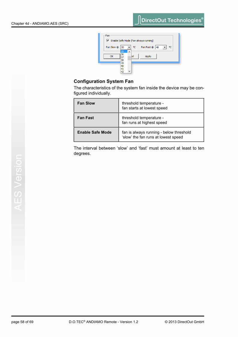
Confi guration System FanThe characteristics of the system fan inside the device may be con-fi gured individually.
Fan slow threshold temperature - fan starts at lowest speed
Fan Fast threshold temperature - fan runs at highest speed
enable safe Mode fan is always running - below threshold ‘slow’ the fan runs at lowest speed
The interval between ‘slow’ and ‘fast’ must amount at least to ten degrees.

DirectOut Technologies®
page 59 of 69© 2013 DirectOut GmbH D.O.TEC® ANDIAMO Remote - Version 1.2
Chapter 4d - ANDIAMO.AES (SRC)A
ES
Version
redundancy ModeDevices with two MADI I/Os provide input redundancy.Redundancy modes:
1. Standard - automatic port selection
2. Priority - priority input port selected
3. Off - forced input port selection
Mode description switch over revert
Standard
The fi rst MADI input that detects a valid signal will be used. If this input fails, the device will switch to the other input (if it is locked).
yes no
Priority
The defi ned priority port is always selected automatically if a valid signal is detected. Selection will revert to the priority port, after switch over (due to signal loss).
yes yes
OffAutomatic selection is overriden by forcing the input selection to a specifi c MADI input port.
no no
Pulldown menu with fi ve options. ‘Redundancy active’ is the default setting (‘Standard’).
The LED of the forced input port is framed by a blue rectangle.
The MADI output ports work in parallel.
The redundancy setting is always set to ‘Standard’ at switch on of the device.

DirectOut Technologies®
page 60 of 69 © 2013 DirectOut GmbHD.O.TEC® ANDIAMO Remote - Version 1.2
Chapter 4d - ANDIAMO.AES (SRC)A
ES
Ver
sion
A green label indicates activated delay compensation.
delay CompensationDelay compensation becomes active, if a device of the ANDIAMO series ‘sees’ another ANDIAMO device at its input. The ‘second’ device will switch to ID 02 automatically.
STATE view:
Consult the ‘Hardware Guide’ for more information about delay compensation.
The USB embedder is deactivated by default after switch on of the device. See „Embedding serial data“ on page 18.
usb embedderThe USB Embedder processes remote control data between the local USB port and the MADI I/O. It can be used to control multiple devices.

DirectOut Technologies®
page 61 of 69© 2013 DirectOut GmbH D.O.TEC® ANDIAMO Remote - Version 1.2
Chapter 4d - ANDIAMO.AES (SRC)A
ES
Version
routing Matrix
With ‘Matrix Mode’ enabled the settings of the matrix will effect the routing of the audio signals.The matrix shows 32 inputs (horizontal) by 32 outputs (vertical).
There are four input pages (sources) and four output pages (desti-nations):
aes 1..32 AES inputs 1 to 32 (port 1 to 16)
aes 33.64 AES inputs 33 to 64 (port 17 to 32)
MadI 1..32 MADI channel 01-32 (input / output)
MadI 33..64 MADI channel 33-64 (input / output)
Click the buttons to change the view of sources / destinations.

DirectOut Technologies®
page 62 of 69 © 2013 DirectOut GmbHD.O.TEC® ANDIAMO Remote - Version 1.2
Chapter 4d - ANDIAMO.AES (SRC)A
ES
Ver
sion
setting / deleting crosspoints• move the cursor to the desired position - a small green square
and transparent bars point the active position
• click into the square to set / delete the crosspoint
To set more than one crosspoint you may click and hold the left mouse button and move the cursor. The pointed crosspoints will be set upon release of the mouse button.
crosspoint - output is set on the selected input page.
crosspoint - output is set on a non-se-lected input page.
DirectOut Technologies®
page 63 of 69© 2013 DirectOut GmbH D.O.TEC® ANDIAMO Remote - Version 1.2
Chapter 5 - Presets
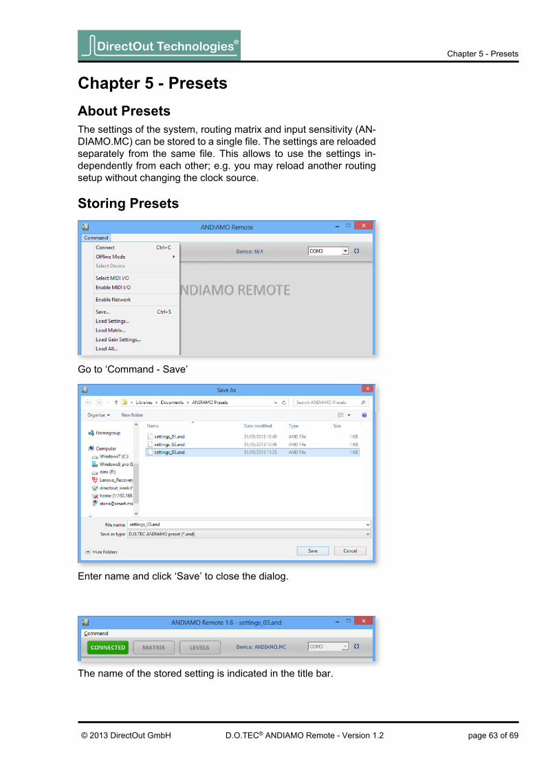
Chapter 5 - presetsabout presetsThe settings of the system, routing matrix and input sensitivity (AN-DIAMO.MC) can be stored to a single fi le. The settings are reloaded separately from the same fi le. This allows to use the settings in-dependently from each other; e.g. you may reload another routing setup without changing the clock source.
storing presets
Go to ‘Command - Save’
Enter name and click ‘Save’ to close the dialog.
The name of the stored setting is indicated in the title bar.

DirectOut Technologies®
page 64 of 69 © 2013 DirectOut GmbHD.O.TEC® ANDIAMO Remote - Version 1.2
Chapter 5 - Presets
reloading presets
Select the fi le (.and) and click ‘open’ to close the dialog and pro-ceed.
Go to ‘Command - Load Settings’ to load system settings.orGo to ‘Command - Load Matrix’ to load routing matrix.or Go to ‘Command - Load Gain Settings’ to load settings of input sen-sitivity.orGo to ‘Command - Load All’ to load all settings at once.

DirectOut Technologies®
page 65 of 69© 2013 DirectOut GmbH D.O.TEC® ANDIAMO Remote - Version 1.2
Chapter 5 - Presets
A safety dialog prompts if the connection to the device is active:
• Click ‘Yes’ to proceed with reloading.
• Click ‘No’ to abort the operation.
If no device is connected (offl ine mode) reloading is executed with-out safety dialog.
The name of the loaded setting is indicated in the title bar.

DirectOut Technologies®
page 66 of 69 © 2013 DirectOut GmbHD.O.TEC® ANDIAMO Remote - Version 1.2
Chapter 5 - Presets
Offl ine ModeThe offl ine mode allows to create or modify settings without an ac-tive connection to the device.
Go to ‘Command - Offl ine Mode’ and select the device to activate / deactivate the offl ine mode.
The status bar (bottom right corner) indicates ‘Not Connected’; i.e. Offl ine Mode is active.
Depending on the connected device the view may differ.

DirectOut Technologies®
page 67 of 69© 2013 DirectOut GmbH D.O.TEC® ANDIAMO Remote - Version 1.2
Chapter 5 - Presets
‘Connect’ will terminate the offl ine mode. A safety dialog prompts before connecting:
• Click ‘Yes’ to overwrite all settings inside the device.
• Click ‘No’ to read all settings from device into software.
Before closing the application a safety dialog prompts:
• Click ‘Yes’ to save all changes to a preset.
• Click ‘No’ to discard all changes and close the application.
• Click ‘Cancel’ to continue with offl ine mode.

DirectOut Technologies®
page 68 of 69 © 2013 DirectOut GmbHD.O.TEC® ANDIAMO Remote - Version 1.2
Error Messages
error Messages
The selected COM port has no connection with the device. ‘Discon-nect’ and check the connection (cabling, COM port).
Possible reason: Abnormal termination of the connectionCheck the cabling or if connected device has been switched off.
No MIDI device is installed. Try to connect using USB or ‘Serial over MADI’ (needs installed D.O.TEC® USB Serial driver).
The actual fi rmware of the device is not fully compatible with the ver-sion of the remote software. A fi rmware update is required.

DirectOut Technologies®
page 69 of 69© 2013 DirectOut GmbH D.O.TEC® ANDIAMO Remote - Version 1.2
Index
Indexb
Bank see Standard Bank Routing
CClock
AES............................................................ 55ANDIAMO .................................................. 20MC ............................................................. 40XT / XT SRC .............................................. 31
CrosspointsAES............................................................ 62ANDIAMO .................................................. 27MC ............................................................. 47XT / XT SRC .............................................. 38
dDelay Compensation
AES............................................................ 60ANDIAMO .................................................. 25MC ............................................................. 45XT / XT SRC .............................................. 36
Display Dark _____________________ 45Display Peak Hold _________________ 48DO.Net see USB: over Ethernet
eEmbedding ______________________ 18
FFader linking _____________________ 50Fan ___________________ 23, 34, 43, 58Firmware
mismatch ................................................... 68update see Hardware Guide
lLevel analog
ANDIAMO .................................................. 21MC ....................................................... 41, 48XT / XT SRC .............................................. 32
MMADI Format ____________ 21, 32, 41, 56Matrix Mode
AES............................................................ 57ANDIAMO .................................................. 22MC ............................................................. 42XT / XT SRC .............................................. 33
MIDI over MADI ___________________ 13
oOffline Mode _____________________ 66
pPresets _________________________ 63
preparing see Offline Mode
rRedundancy Mode
AES............................................................ 59ANDIAMO .................................................. 24MC ............................................................. 44XT / XT SRC .............................................. 35
Routing MatrixAES............................................................ 61ANDIAMO .................................................. 26MC ............................................................. 46XT / XT SRC .............................................. 37
sSample Rate
AES............................................................ 55ANDIAMO .................................................. 21MC ............................................................. 41XT / XT SRC .............................................. 31
Sample Rate Conversion ________ 31, 55Serial over MADI __________________ 13Standard Bank Routing
AES............................................................ 56ANDIAMO .................................................. 22MC ............................................................. 42XT / XT SRC .............................................. 32
uUSB
Embedder ................................ 25, 36, 45, 60over Ethernet ............................................. 13
User Bit Transparency ______________ 34
WWarnings _________________________ 6