directly probing the mechanical properties of the spindle
TRANSCRIPT

Directly Probing the MechanicalProperties of the Spindle and Its Matrix
The Harvard community has made thisarticle openly available. Please share howthis access benefits you. Your story matters
Citation Gatlin, Jesse C., Alexandre Matov, Gaudenz Danuser, TimothyJ. Mitchison, and Edward D. Salmon. 2010. Directly probing themechanical properties of the spindle and its matrix. The Journal ofCell Biology 188(4): 481-489.
Published Version doi://10.1083/jcb.200907110
Citable link http://nrs.harvard.edu/urn-3:HUL.InstRepos:10230117
Terms of Use This article was downloaded from Harvard University’s DASHrepository, and is made available under the terms and conditionsapplicable to Other Posted Material, as set forth at http://nrs.harvard.edu/urn-3:HUL.InstRepos:dash.current.terms-of-use#LAA

The Rockefeller University Press $30.00J. Cell Biol. Vol. 188 No. 4 481–489www.jcb.org/cgi/doi/10.1083/jcb.200907110 JCB 481
JCB: Report
Correspondence to Jesse C. Gatlin: [email protected]. Danuser’s present address is Harvard Medical School, Boston, MA 02115.Abbreviations used in this paper: CSF, cytostatic factor; DIC, dynein intermediate chain; NuMA, nuclear mitotic apparatus protein.
IntroductionProper assembly of meiotic/mitotic spindles at metaphase yields bipolar structures with cell type–specific steady-state lengths. This spindle morphology is a prerequisite for accurate chromo-some segregation. Despite the relatively rapid turnover of its dynamic microtubule building blocks, the spindle achieves a steady-state length that is determined by the concerted action of microtubule dynamics, motors, and other spindle-associated proteins (Walczak and Heald, 2008). How this self-assembly process is achieved is still not fully understood, but it is clear that forces play a critical role.
The current thinking is that steady-state spindle length is determined by a force-balance mechanism in which outward-directed forces that push the spindle poles apart are antagonized by inward-directed forces that pull them together (Mogilner et al., 2006). In higher eukaryotes, the plus end–directed kinesin-5 (Eg5 in Xenopus laevis) is thought to slide oppositely oriented microtubules that overlap in the spindle midzone in a microtubule minus end direction toward opposite poles. This
produces persistent poleward movement of microtubules within each spindle half, which is called flux (Sawin and Mitchison, 1991; Miyamoto et al., 2004), and generates an outward pushing force that works to keep the spindle poles spatially separated (Sharp et al., 1999; Mitchison et al., 2005). Minus end–directed motor complexes such as dynein–dynactin and kinesin-14 family members have been shown to produce forces on spindle poles that antagonize kinesin-5 in determining meta-phase spindle length (Mitchison et al., 2005; Tanenbaum et al., 2008; Ferenz et al., 2009). It is clear that these motor-driven pushing and pulling forces depend on microtubules, but an elas-tic, nonmicrotubule spindle matrix has also been proposed to be an important mechanical component of the spindle (Pickett-Heaps and Forer, 2009; for review see Scholey et al., 2001). Indeed, an elastic matrix of sufficient strength could mechani-cally influence spindle length by opposing forces generated within the spindle by microtubule-dependent motors (Goshima et al., 2005; Mitchison et al., 2005) or by serving as a scaffold
Several recent models for spindle length regulation propose an elastic pole to pole spindle matrix that is sufficiently strong to bear or antagonize forces
generated by microtubules and microtubule motors. We tested this hypothesis using microneedles to skewer meta-phase spindles in Xenopus laevis egg extracts. Microneedle tips inserted into a spindle just outside the metaphase plate resulted in spindle movement along the interpolar axis at a velocity slightly slower than microtubule poleward flux, bringing the nearest pole toward the needle. Spindle velocity decreased near the pole, which often split apart
slowly, eventually letting the spindle move completely off the needle. When two needles were inserted on either side of the metaphase plate and rapidly moved apart, there was minimal spindle deformation until they reached the poles. In contrast, needle separation in the equatorial direction rapidly increased spindle width as constant length spindle fibers pulled the poles together. These observa-tions indicate that an isotropic spindle matrix does not make a significant mechanical contribution to metaphase spindle length determination.
Directly probing the mechanical properties of the spindle and its matrix
Jesse C. Gatlin,1,4 Alexandre Matov,2 Gaudenz Danuser,2 Timothy J. Mitchison,3,4 and Edward D. Salmon1,4
1Department of Biology, University of North Carolina at Chapel Hill, Chapel Hill, NC 275992Laboratory for Computational Cell Biology, Department of Cell Biology, The Scripps Research Institute, La Jolla, CA 920373Department of Systems Biology, Harvard Medical School, Boston, MA 021154Cell Division Group, Marine Biological Laboratory, Woods Hole, MA 02543
© 2010 Gatlin et al. This article is distributed under the terms of an Attribution–Noncommercial–Share Alike–No Mirror Sites license for the first six months after the pub-lication date (see http://www.rupress.org/terms). After six months it is available under a Creative Commons License (Attribution–Noncommercial–Share Alike 3.0 Unported license, as described at http://creativecommons.org/licenses/by-nc-sa/3.0/).
TH
EJ
OU
RN
AL
OF
CE
LL
BIO
LO
GY

JCB • VOLUME 188 • NUMBER 4 • 2010 482
the whole spindle in the opposite direction if not constrained by a spindle matrix.
In 24 out of 27 cases, the spindle pushed itself along its interpolar axis, in the expected direction, until it moved all of the way off the microneedle (Fig. 2 A and Video 1). In the three cases in which the spindle did not move past the needle, the spindle was skewered very close to the exact middle of the spindle and likely became entangled in chromatin. Inhibition of microtubule sliding using AMP-PNP (Sawin and Mitchison, 1991) blocked movement of the spindle relative to the skewer-ing needle (Fig. 3 C), suggesting that movement of the spindle relative to the needle is likely caused by the same forces that produce microtubule sliding, presumably kinesin-5 activity (Miyamoto et al., 2004). Spindles sometimes rotated around the microneedles (e.g., Fig. 2 A, spindles 2 and 3) because of transient and changing flows within the extracts on the cover-slip. This rotation allowed the interpolar axis of the spindle to align in the direction of the extract flow, thereby increasing the contribution of viscous drag forces to spindle movement along the same axis. We attempted to reduce the influence of these forces on spindle movement by skewering spindles with two microneedles, each inserted through the same spindle half along the interpolar axis. This prevented spindle rotation and relegated the contribution of the flow forces to the vector component pro-jected on the needle to needle axis (the white arrow in Fig. 2 D indicates the most persistent direction of flow). In each case, the spindle moved along the axis formed by the two needles and then eventually pushed itself completely off both needles (n = 15). It should also be noted that in some single needle experiments, extract flow was noticeably less pronounced, producing instances in which two separate spindles in the same field, each skewered by a single needle, moved in different directions but at similar rates (Video 2). Collectively, these data strongly suggest that the observed spindle movements are mainly the result of force-generating mechanisms within the spindle.
The rate of spindle escape off single skewering needles was measured by kymography and manual tracking. Kymographs demonstrate that the spindles did not undergo a change in length and instead moved relative to the skewering needle as a rigid body (Fig. 2 B). By manual tracking, the average mean velocity of approach of the pole to the needle was 1.7 ± 0.4 µm/min for all distances >5 µm from the pole. This means that in most of the central half-spindle, spindle translocation rela-tive to the needle occurred with a mean velocity close to the
for kinesins and dyneins that slide microtubules (Kapoor and Mitchison, 2001; Tsai et al., 2006).
Although several spindle matrix proteins/molecules have been identified (Walker et al., 2000; Chang et al., 2004; Qi et al., 2004; Tsai et al., 2006; Fabian et al., 2007), there is still uncertainty in the spindle mechanics field about whether these spindle matrices make mechanical contributions to the deter-mination of spindle length. In this study, we use microneedle manipulation to directly probe the mechanics of metaphase spindles in Xenopus egg extracts. Our findings not only address issues about the mechanical properties and structural organi-zation of the spindle matrix but also have implications for the distribution and mechanical properties of lateral linkages between microtubules within the spindle.
Results and discussionIntrinsic forces push skewered spindles off stationary microneedlesWe assembled meiosis II spindles in Xenopus egg extracts as described previously (Murray, 1991; Gatlin et al., 2009) and visualized them by the addition of trace X-rhodamine–labeled tubulin or polarization microscopy. A small aliquot of extract with assembled spindles was spread on a coverslip surface passivated with a hydrophobic film to minimize adventitious protein binding, covered with a thin layer of mineral oil to prevent evaporation, and mounted on an inverted microscope. This open setup allowed access for two micromanipulator-controlled microneedles. The needles were bent near their tips at an 70° angle so that their tips could be pushed vertically through a spindle, pinning it to the coverslip (Fig. 1 A). The needle tips were also passivated.
In initial experiments, a single needle was pushed through a spindle at a point lying on the spindle interpolar axis and just poleward of its equator to avoid entanglements with chromosome arms (Fig. 1 B). Near the initial needle inser-tion point, more microtubules are oriented with their plus ends toward the equator than the other way around, and thus the majority of microtubules slide toward the pole closest to the needle (Burbank et al., 2006; Yang et al., 2008). As the spin-dle fiber microtubules flux poleward, molecular cross-links between adjacent microtubules, if present and unbroken, would be expected to move with the fluxing microtubules. Such cross-links would push against the fixed needle and move
Figure 1. Experimental approach for spindle skewering. (A) The cartoon shows the experimental setup used in all skewering experiments (see Materials and methods for more details). (B) Example of a skewered spindle visualized by the addition of X-rhodamine– labeled tubulin to the extract. The cross section of the microneedle is seen as a dark annulus. Bar, 25 µm.

483An isotropic spindle matrix is mechanically weak • Gatlin et al.
same responsible for producing flux, can push against a skewer-ing microneedle.
Spindle translocation velocity slows as the needle encounters a poleWithin 5 µm of the spindle pole, the velocity of spindle move-ment past the needle decreased to 0.8 ± 0.4 µm/min, which is significantly slower than for most of the half-spindle (P < 0.05 by Student’s t test for equal means; n = 24). The rate of micro-tubule sliding near the pole is currently controversial; in a single molecule study, sliding rates at 80% of the equatorial value were reported (Yang et al., 2008), whereas a study using an averaging method reported that sliding slows to near zero veloc-ity at the pole (Burbank et al., 2007). Therefore, from velocity
range of values reported for flux velocities in Xenopus extract spindles (2 µm/min in the central region; Desai et al., 1998; Maddox et al., 2003b; Yang et al., 2007). High-resolution and confocal fluorescence speckle microscopy and computer-aided tracking were used to determine flux rates in skewered spindles (see Materials and methods). For the example in Fig. S1, the mean flux rate was similar to the measured rate of spindle translocation in the opposite direction. Although we concede that the flux-like rates of spindle movement observed do not prove a causal relationship, because we can exclude extrinsic mechanisms, it is difficult to conceive of some other intrinsic force-generating mechanism capable of producing the observed spindle movements. Thus, these observations suggest that intrinsically generated spindle forces, likely the
Figure 2. Intrinsic spindle forces move impaling microneedles through the spindle. (A) Images shown were selected from three time-lapse series of skewered spindles. Dashed lines indicate the position of the microneedle, which remained essentially stationary during the experimental time course. (B) Kymographs were used to analyze velocities of spindles as they translocated off microneedles. Because skewered spindles often rotated during time-lapse experiments as the result of changing flows within the extract (e.g., spindle #3), each image in the series was rotated using custom software to maintain a fixed orientation of the spindle’s interpolar axis (arrowheads mark the position of the needle). (C) The distance between the nearest pole and the middle of the needle was plotted versus time. Slopes were calculated using linear regressions from these plots of pole to needle distances of >5 µm and those equal to 5 µm. (D) Two microneedles were used to impale spindles. In each case, the needles were positioned on the same side of the spindle midzone, and the spindle moved off both needles, regardless of the predominant direction of extract flow (indicated by the white arrow). Dashed lines indicate the position of the microneedles used to skewer the spindles. Bars, 25 µm.

JCB • VOLUME 188 • NUMBER 4 • 2010 484
Figure 3. Intrinsic forces push but do not pull the spindle off impaling microneedles. (A) The time-lapse series shows the dynamic morphology of a spindle pole, labeled with Alexa Fluor 488 anti-NuMA antibodies (green), as it is split by a microneedle. Spindles continued to move despite a lack of any detect-able microtubules (red) on the distal side of the microneedle. (B) Time-lapse images show the behavior of skewered spindles 5–10 min after the addition of function-perturbing antibodies against the 70.1-kD DIC (anti-DIC). The distance between the metaphase plate and the needle were measured and plotted as a function of time for multiple spindles in the corresponding graph. (C) Assembled spindles were treated with 1.5 µM AMP-PNP and skewered within 5–10 min after treatment. AMP-PNP at this concentration inhibited flux, in agreement with nearly horizontal plots of needle to spindle midpoint distance versus time (graph). (B and C) Dashed lines indicate the position of the microneedle used to skewer the spindles. Bars: (A) 5 µm; (B and C) 25 µm.
485An isotropic spindle matrix is mechanically weak • Gatlin et al.
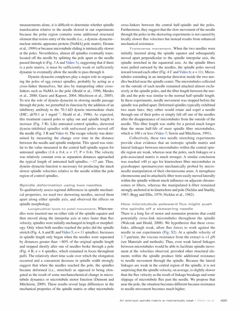
cross-linkers between the central half-spindle and the poles. Furthermore, they suggest that the slow movement of the needle through the poles in the skewering experiments is not caused by locally slower flux velocities but instead results from enhanced mechanical resistance.
Transverse movement. When the two needles were initially inserted along the spindle equator and subsequently moved apart perpendicular to the spindle interpolar axis, the spindle stretched in the equatorial axis. As the spindle fibers were pulled outward by the needles, the spindle poles moved inward toward each other (Fig. 4 C and Video 6; n = 11). Micro-tubules extending in an interpolar direction inside the two nee-dles buckled near the spindle center. The microtubules collected on the outside of each needle remained attached almost exclu-sively at the spindle poles, and the fiber length between the nee-dle and the pole was similar to the normal half-spindle length. In these experiments, needle movement was stopped before the spindle was pulled apart. Deformed spindles typically exhibited two main fates: they either would rotate and expel a needle through one of their poles or simply fall off one of the needles after the disappearance of microtubules from the outside of the needle. This fiber length was stable for a period much longer than the mean half-life of most spindle fiber microtubules, which is 100 s or less (Video 7; Sawin and Mitchison, 1991).
Collectively, these two needle stretching experiments provide clear evidence that an isotropic spindle matrix and lateral linkages between microtubules within the central spin-dle region are weak, whereas near the poles, such linkages or a pole-associated matrix is much stronger. A similar conclusion was reached >40 yr ago for kinetochore fiber microtubules in grasshopper spermatocytes mechanically probed by micro-needle manipulation of their chromosome arms. A metaphase chromosome and its attached k-fiber were easily moved laterally within the spindle without much influence on adjacent chromo-somes or fibers, whereas the manipulated k-fiber remained strongly anchored at its kinetochore and pole (Nicklas and Staehly, 1967; Begg and Ellis, 1979; Nicklas et al., 1982).
How microtubule poleward flux might push the spindle off a skewering needleThere is a long list of motor and nonmotor proteins that could potentially cross-link microtubules throughout the spindle (Walczak and Heald, 2008). We hypothesize that these cross-links, although weak, allow flux forces to work against the needle in our experiments (Fig. S2). At a spindle velocity of 1.7 µm/min, the viscous resistance from the extract is <1 pN (see Materials and methods). Thus, even weak lateral linkages between microtubules would be able to facilitate spindle move-ment at the velocities observed, provided other structural ele-ments within the spindle produce little additional resistance to needle movement through the spindle. Because the lateral linkages are weak in the central region of the spindle, it is not surprising that the spindle velocity, on average, is slightly slower than the flux velocity as the result of linkage breakage and some slippage of microtubule flux past the needle. We propose that near the pole, the situation becomes different because resistance to needle movement becomes much higher.
measurements alone, it is difficult to determine whether spindle translocation relative to the needle slowed in our experiments because the polar region contains some additional structural element that resists entry of the needle (i.e., a dynein–dynactin–nuclear mitotic apparatus protein [NuMA] pole matrix; Dionne et al., 1999) or because microtubule sliding is intrinsically slower at the poles. Nevertheless, almost all spindles eventually trans-located off the needle by splitting the pole apart as the needle passed through it (Fig. 3 A and Video 3), suggesting that if there is a pole matrix, it must be sufficiently weak or sufficiently dynamic to eventually allow the needle to pass through it.
Dynein–dynactin complexes play a major role in organiz-ing the poles of egg extract spindles, probably by acting as a cross-linker themselves, but also by transporting other cross-linkers such as NuMA to the pole (Heald et al., 1996; Merdes et al., 2000; Gaetz and Kapoor, 2004; Mitchison et al., 2005). To test the role of dynein–dynactin in slowing needle passage through the pole, we perturbed its function by the addition of an inhibitory antibody to the 70.1-kD dynein intermediate chain (DIC; ab70.1 at 1 mgml1; Heald et al., 1996). As expected, this treatment caused poles to splay out and spindle length to increase (Fig. 3 B). Like untreated control spindles, skewered dynein-inhibited spindles with unfocused poles moved off the needle (Fig. 3 B and Video 4). The escape velocity was deter-mined by measuring the change over time in the distance between the needle and spindle midpoint. This speed was simi-lar to the value measured in the central half-spindle region for untreated spindles (1.6 ± 0.4; n = 17; P = 0.4). The velocity was relatively constant even as separation distances approached the typical length of untreated half-spindles, 17 µm. Thus, dynein–dynactin function is necessary for producing the much slower spindle velocities relative to the needle within the pole region of control spindles.
Spindle deformation using two needlesTo qualitatively assess regional differences in spindle mechani-cal properties, we used two skewering needles, moved them apart along either spindle axis, and observed the effects on spindle morphology.
Longitudinal (pole to pole) movement. When nee-dles were inserted one on either side of the spindle equator and then moved along the interpolar axis at rates faster than flux velocity, spindles were initially unchanged in length or morphol-ogy. Only when both needles reached the poles did the spindle stretch (Fig. 4, A and B; and Video 5; n = 11 spindles). Increases in spindle length only began when the needles were separated by distances greater than 80% of the original spindle length and stopped shortly after one of needles broke through a pole (Fig. 4 B; n = 4 spindles, which remained in focus throughout pull). The relatively short time scale over which the elongation occurred and a concurrent decrease in spindle width strongly suggest that when the needles reached the pole, the spindles became deformed (i.e., stretched) as opposed to being elon-gated as the result of some mechanochemical change in micro-tubule dynamics or microtubule motor function (Dumont and Mitchison, 2009). These results reveal large differences in the mechanical properties of the spindle matrix or other microtubule

JCB • VOLUME 188 • NUMBER 4 • 2010 486
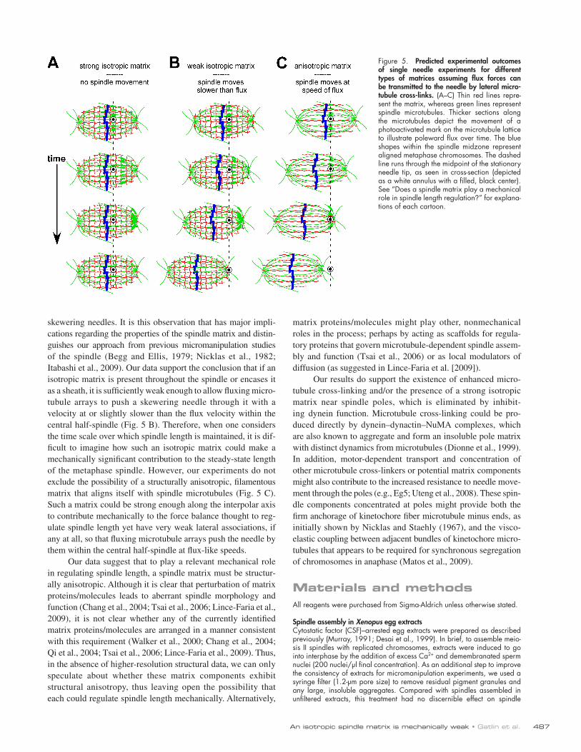
Does a spindle matrix play a mechanical role in spindle length regulation?The rationale for our single needle skewering experiments was based on predictions about resultant spindle movement and re-sistance to this movement by spindle matrices of various struc-ture and material properties (Fig. 5). If the spindles did not move
Figure 4. Lateral interactions between microtubules are more robust near the spindle poles. (A and C) The cartoons show the initial positions of the two skewering needle tips within the spindle and the direction of needle movement. (A) The two needles were initially positioned one on each side of the metaphase plate and then spread apart along the interpolar axis. The images show a representative time-lapse series of a spindle being longitudinally stretched. Dashed lines represent the position of the spindle poles before the onset of stretching. (B) Changes in spindle length during longitudinal stretching (normalized to the initial length of the spindle) are plotted versus time, shown as black lines, whereas corresponding plots of needle separation versus time are shown in red. Matching markers indicate data taken from the same experiment. Percentages are the ratio of needle separation at the onset of spindle elongation to the initial spindle length (elongation onset was arbitrarily defined as the time point at which the spindle became 0.5% longer than its initial length). (C) Spindles were also stretched in the orthogonal direction, transverse to their interpolar axes. In these experiments, spindle deformation began at the onset of needle separation and continued until the needles were stopped. White arrowheads indicate the position of the interpolar axis after transverse spindle stretching. Bars, 25 µm.
at all, it would have been difficult to distinguish between (a) the absence of a force-transmitting linkage between fluxing micro-tubules and the needle or (b) the presence of an isotropic ma-trix of sufficient mechanical strength to completely uncouple needle movement from flux-driven forces (Fig. 5 A). In con-trast, the spindles did move through, and eventually off, the
487An isotropic spindle matrix is mechanically weak • Gatlin et al.
matrix proteins/molecules might play other, nonmechanical roles in the process; perhaps by acting as scaffolds for regula-tory proteins that govern microtubule-dependent spindle assem-bly and function (Tsai et al., 2006) or as local modulators of diffusion (as suggested in Lince-Faria et al. [2009]).
Our results do support the existence of enhanced micro-tubule cross-linking and/or the presence of a strong isotropic matrix near spindle poles, which is eliminated by inhibit-ing dynein function. Microtubule cross-linking could be pro-duced directly by dynein–dynactin–NuMA complexes, which are also known to aggregate and form an insoluble pole matrix with distinct dynamics from microtubules (Dionne et al., 1999). In addition, motor-dependent transport and concentration of other microtubule cross-linkers or potential matrix components might also contribute to the increased resistance to needle move-ment through the poles (e.g., Eg5; Uteng et al., 2008). These spin-dle components concentrated at poles might provide both the firm anchorage of kinetochore fiber microtubule minus ends, as initially shown by Nicklas and Staehly (1967), and the visco-elastic coupling between adjacent bundles of kinetochore micro-tubules that appears to be required for synchronous segregation of chromosomes in anaphase (Matos et al., 2009).
Materials and methodsAll reagents were purchased from Sigma-Aldrich unless otherwise stated.
Spindle assembly in Xenopus egg extractsCytostatic factor (CSF)–arrested egg extracts were prepared as described previously (Murray, 1991; Desai et al., 1999). In brief, to assemble meio-sis II spindles with replicated chromosomes, extracts were induced to go into interphase by the addition of excess Ca2+ and demembranated sperm nuclei (200 nuclei/µl final concentration). As an additional step to improve the consistency of extracts for micromanipulation experiments, we used a syringe filter (1.2-µm pore size) to remove residual pigment granules and any large, insoluble aggregates. Compared with spindles assembled in unfiltered extracts, this treatment had no discernible effect on spindle
skewering needles. It is this observation that has major impli-cations regarding the properties of the spindle matrix and distin-guishes our approach from previous micromanipulation studies of the spindle (Begg and Ellis, 1979; Nicklas et al., 1982; Itabashi et al., 2009). Our data support the conclusion that if an isotropic matrix is present throughout the spindle or encases it as a sheath, it is sufficiently weak enough to allow fluxing micro-tubule arrays to push a skewering needle through it with a velocity at or slightly slower than the flux velocity within the central half-spindle (Fig. 5 B). Therefore, when one considers the time scale over which spindle length is maintained, it is dif-ficult to imagine how such an isotropic matrix could make a mechanically significant contribution to the steady-state length of the metaphase spindle. However, our experiments do not exclude the possibility of a structurally anisotropic, filamentous matrix that aligns itself with spindle microtubules (Fig. 5 C). Such a matrix could be strong enough along the interpolar axis to contribute mechanically to the force balance thought to reg-ulate spindle length yet have very weak lateral associations, if any at all, so that fluxing microtubule arrays push the needle by them within the central half-spindle at flux-like speeds.
Our data suggest that to play a relevant mechanical role in regulating spindle length, a spindle matrix must be structur-ally anisotropic. Although it is clear that perturbation of matrix proteins/molecules leads to aberrant spindle morphology and function (Chang et al., 2004; Tsai et al., 2006; Lince-Faria et al., 2009), it is not clear whether any of the currently identified matrix proteins/molecules are arranged in a manner consistent with this requirement (Walker et al., 2000; Chang et al., 2004; Qi et al., 2004; Tsai et al., 2006; Lince-Faria et al., 2009). Thus, in the absence of higher-resolution structural data, we can only speculate about whether these matrix components exhibit structural anisotropy, thus leaving open the possibility that each could regulate spindle length mechanically. Alternatively,
Figure 5. Predicted experimental outcomes of single needle experiments for different types of matrices assuming flux forces can be transmitted to the needle by lateral microtubule crosslinks. (A–C) Thin red lines repre-sent the matrix, whereas green lines represent spindle microtubules. Thicker sections along the microtubules depict the movement of a photoactivated mark on the microtubule lattice to illustrate poleward flux over time. The blue shapes within the spindle midzone represent aligned metaphase chromosomes. The dashed line runs through the midpoint of the stationary needle tip, as seen in cross-section (depicted as a white annulus with a filled, black center). See “Does a spindle matrix play a mechanical role in spindle length regulation?” for explana-tions of each cartoon.
JCB • VOLUME 188 • NUMBER 4 • 2010 488
Calculations of viscous drag force on spindles in Xenopus egg extractsThe viscous force resisting spindle movements in the Xenopus egg extract is dependent on the viscosity of the extract, the geometry of the micro-tubule array, and the velocity at which the array is moved. At low Reynolds numbers, the drag forces acting on a spindle modeled as a solid, prolate ellipsoid and moving at a velocity u in a fluid of viscosity is
Fru
r h||||
ln / /,= ( ) −
42 1 2
πη
where r is the longest semiaxis of the ellipse and h is the shortest semiaxis of the ellipse (Perrin, 1934; Berg, 1983).
The viscosity of crude interphase extracts has been measured at 20 mPa-s (Valentine et al., 2005), and the velocities of spindle move-ments in these experiments are in the order of 2 µm/min. For a typical spindle in our experiments, r/h is 2 with an r of 17 µm. Substituting these numbers into the aforementioned equation for F|| (i.e., spindles sliding parallel to their long axes) yields F|| 0.2 pN.
Determining the rate of flux in a skewered spindleWe measured the rate of spindle translocation relative to a stationary skewering needle by manually tracking the nearest pole and calculating the distance between it and the needle as a function of time (Fig. S1 A). This velocity, Vspindletrans, was 2.3 µm/min determined by linear regression (R2 = 0.99). Confocal fluorescent speckle microscopy (Maddox et al., 2003a) was used to image microtubule flux within the skewered spindle on a microscope (Eclipse TE300; Nikon; differential interference contrast 60× NA 1.4). Acquisition was controlled with MetaMorph software, and all images were acquired at room temperature (22°C). A computer-based tracking method that utilizes an optimal-flow minimum-cost correspondence assignment was used to track speckle flows (Yang et al., 2005). Four main directional components (along the interpolar and equatorial axes of the spindle) and the corresponding vectors for each were extracted, insuring that velocity contributions from spindle rotations were isolated from speckle flows along the interpolar axis. The results presented in Fig. S1 B are for those flows running parallel to the pole to pole axis and directed toward the pole farthest from the needle. The mean velocity of these speckles, Vspeckles, was measured as 4.6 ± 1.4 µm/min (n = 189 tracks; Fig. S1 C). Because the spindle is moving in the same direction as this flux Vspeckles = Vflux + Vspindletrans. Substituting our measured values of Vspeckles and Vspindletrans, Vflux is 2.3 ± 1.4 µm/min. In this case, the spindle translocates off the needle at the same mean speed of its flux.
Online supplemental materialFig. S1 shows the computer-aided tracking of microtubule flux in a skew-ered metaphase spindle. Fig. S2 shows a model for how flux pushes against the needle. Video 1 shows time-lapse fluorescence imaging of spindle escape off a single skewering needle. Video 2 shows time-lapse fluorescence imaging of two spindles in the same frame escaping their needles in different directions. Video 3 shows time-lapse fluores-cence imaging of a skewering needle moving through a spindle pole. Video 4 shows time-lapse fluorescence imaging of spindle escape after treatment with concentrated anti-DIC antibodies. Videos 5 and 6 show time-lapse fluorescence imaging of two-needle separation along the interpolar spindle axis (longitudinal stretching) and orthogonal to the interpolar spindle axis (transverse stretching), respectively. Video 7 shows time-lapse fluorescence imaging of spindle behavior after a transverse stretch. Online supplemental material is available at http://www.jcb .org/cgi/content/full/jcb.200907110/DC1.
We would like to thank all current members of the Salmon laboratory and the Marine Biological Laboratory (MBL) Cell Division Group, especially T. Maresca, for many insightful discussions about the work. We also thank T. Maresca, A. Groen, S. Dumont, and M. Wuhr for critical readings of the original and revised manuscripts. A special thanks goes to H. Luther and M. Peterson for their help with acquiring necessary equipment while working at the MBL.
This work was supported by National Institute of General Medicine grants to J.C. Gatlin (F32GM080049) and E.D. Salmon (GM24364). T.J. Mitchison was funded by a grant from the National Cancer Institute (CA078048-09).
Submitted: 17 July 2009Accepted: 25 January 2010
assembly or morphology. Extracts were then incubated at 18°C for 1 h to allow for DNA replication and driven into metaphase by the addition of an equal volume of CSF extract. To more readily visualize needles within the spindle, X-rhodamine–labeled tubulin was prepared as previously de-scribed (Yang et al., 2007) and added to extracts at a final concentration of 5 µgml1 immediately after add-back of CSF-arrested extract to the spindle assembly reactions. Spindles were then allowed to assemble for 1–1.5 h at 18°C before experimentation.
Preparation of coverslipsOur skewering experiments were performed on or near the coverslip surface. So, to limit adventitious binding of motors and other proteins that could potentially influence the movements of skewered spindles, we acid washed our coverslips (#1.5 thickness; Corning) as described pre-viously (Waterman-Storer et al., 1999). The coverslips were then dried under a stream of nitrogen and silanized by immersion in a solution of 0.05% dichlorodimethylsilane (Fluka) in trichloroethylene for 2 h. Silanized coverslips were rinsed in methanol with bath sonication for 5 min (three times) and then in double-distilled water for 5 min (three times) and allowed to air dry until use. Before experimentation, treated coverslips were covered in Xenopus buffer (Desai et al., 1999) with 1% Pluronic F-127, a hydrophobic coblock polymer (Varga et al., 2006). After at least 10 min, the Xenopus buffer + Pluronic buffer was removed, and the coverslip was rinsed under a stream of double-distilled water. Any residual rinse was removed by tilting the coverslip and wiping its edge using a Kim wipe.
Spindle micromanipulation and imagingThe microneedles used for spindle manipulation were made by pulling boroscillate glass micropipettes using a micropipette puller (model P-97; Sutter Instrument Co.). The distal tips were bent at angles ranging from 60 to 90° by heating the needle on its bottom side with a microforge filament (MF-830; Narishige). The bent needles were then silanized and coated with Pluronic F-127 as described in the previous section for coverslips.
Chambers used for all skewering experiments were prepared as described previously (Gatlin et al., 2009). In brief, a 22-mm diameter coverslip was adhered to a preheated metal slide using VALAP (1:1:1 vasoline, lanolin, and paraffin) applied around a circular cutout in the slide. This formed a shallow well with the coverslip acting as the bottom. A small aliquot (5–7 µl) of extract was spread over the surface of the coverslip with a pipette tip and overlaid with 300 µl of mineral oil (embryo tested from Sigma-Aldrich) to prevent the sample from drying out during subsequent imaging.
Micromanipulation/skewering experiments were conducted on an inverted microscope (TE2000e; Nikon) stand equipped with a motorized microscope stage (Applied Scientific Instrumentation). Dual manual micro-manipulators (Narishige) were mounted directly to the condenser arm of the microscope and adjusted so the shafts of opposing needles entered the well at shallow angles with the bent needle tips nearly perpendicular to the coverslip surface. Needles were lowered through the mineral oil over-lay and into the extract for skewering. Polarization optics (i.e., a crossed polarizer and analyzer) in combination with a 20× differential interference contrast objective (20× NA 0.75 MImm; Plan Fluor; Nikon) were used to visualize spindles during skewering. For subsequent imaging of spindle escape, we used epifluorescence microscopy to view spindle-incorporated X-rhodamine–tubulin (as prepared in Waterman-Storer et al. [1999]). Where indicated, pole localization of NuMA was visualized using anti-NuMA antibodies directly labeled with Alexa Fluor 488 (Invitrogen; a gift from A. Groen, Yale University, New Haven, CT). Images were acquired using a cooled charge-coupled device camera (Orca-ER; Hamamatsu Photonics) mounted on the right-hand side of the microscope stand to a port that received 80% of the emitted light, with the remaining 20% going to the eyepieces. This setup allowed us to manipulate and image spindles during transverse and longitudinal stretching experiments. These experi-ments were conducted at 20°C. All image acquisition and analyses were performed using MetaMorph software (MDS Analytical Technologies). For kymograph analysis of spindle escape, rotation of acquired image stacks was performed using custom Matlab software written by J.C. Gatlin. Unless otherwise stated, at least three different extracts were used for each experimental condition.
Statistical analysesExcel software (Microsoft) was used for all statistical analysis and graph-ing. Unless otherwise indicated, reported results are expressed as mean values ± standard deviations.

489An isotropic spindle matrix is mechanically weak • Gatlin et al.
Merdes, A., R. Heald, K. Samejima, W.C. Earnshaw, and D.W. Cleveland. 2000. Formation of spindle poles by dynein/dynactin-dependent transport of NuMA. J. Cell Biol. 149:851–862. doi:10.1083/jcb.149.4.851
Mitchison, T.J., P. Maddox, J. Gaetz, A. Groen, M. Shirasu, A. Desai, E.D. Salmon, and T.M. Kapoor. 2005. Roles of polymerization dynamics, opposed motors, and a tensile element in governing the length of Xenopus extract meiotic spindles. Mol. Biol. Cell. 16:3064–3076. doi:10.1091/mbc.E05-02-0174
Miyamoto, D.T., Z.E. Perlman, K.S. Burbank, A.C. Groen, and T.J. Mitchison. 2004. The kinesin Eg5 drives poleward microtubule flux in Xenopus laevis egg extract spindles. J. Cell Biol. 167:813–818. doi:10.1083/jcb.200407126
Mogilner, A., R. Wollman, G. Civelekoglu-Scholey, and J. Scholey. 2006. Modeling mitosis. Trends Cell Biol. 16:88–96. doi:10.1016/j.tcb.2005.12.007
Murray, A.W. 1991. Cell cycle extracts. Methods Cell Biol. 36:581–605. doi:10.1016/S0091-679X(08)60298-8
Nicklas, R.B., and C.A. Staehly. 1967. Chromosome micromanipulation. I. The mechanics of chromosome attachment to the spindle. Chromosoma. 21:1–16. doi:10.1007/BF00330544
Nicklas, R.B., D.F. Kubai, and T.S. Hays. 1982. Spindle microtubules and their mechanical associations after micromanipulation in anaphase. J. Cell Biol. 95:91–104. doi:10.1083/jcb.95.1.91
Perrin, F. 1934. Mouvement brownien d’un ellipsoide - I. Dispersion diélec-trique pour des molécules ellipsoidales. J. Phys. Radium. 5:497–511. doi:10.1051/jphysrad:01934005010049700
Pickett-Heaps, J., and A. Forer. 2009. Mitosis: spindle evolution and the matrix model. Protoplasma. 235:91–99. doi:10.1007/s00709-009-0030-2
Qi, H., U. Rath, D. Wang, Y.Z. Xu, Y. Ding, W. Zhang, M.J. Blacketer, M.R. Paddy, J. Girton, J. Johansen, and K.M. Johansen. 2004. Megator, an essential coiled-coil protein that localizes to the putative spindle matrix during mitosis in Drosophila. Mol. Biol. Cell. 15:4854–4865. doi:10.1091/mbc.E04-07-0579
Sawin, K.E., and T.J. Mitchison. 1991. Poleward microtubule flux mitotic spindles assembled in vitro. J. Cell Biol. 112:941–954. doi:10.1083/jcb.112.5.941
Scholey, J.M., G.C. Rogers, and D.J. Sharp. 2001. Mitosis, microtubules, and the matrix. J. Cell Biol. 154:261–266. doi:10.1083/jcb.200101097
Sharp, D.J., K.R. Yu, J.C. Sisson, W. Sullivan, and J.M. Scholey. 1999. Antagonistic microtubule-sliding motors position mitotic centrosomes in Drosophila early embryos. Nat. Cell Biol. 1:51–54. doi:10.1038/9025
Tanenbaum, M.E., L. Macůrek, N. Galjart, and R.H. Medema. 2008. Dynein, Lis1 and CLIP-170 counteract Eg5-dependent centrosome separation during bipolar spindle assembly. EMBO J. 27:3235–3245. doi:10.1038/emboj .2008.242
Tsai, M.Y., S. Wang, J.M. Heidinger, D.K. Shumaker, S.A. Adam, R.D. Goldman, and Y. Zheng. 2006. A mitotic lamin B matrix induced by RanGTP re-quired for spindle assembly. Science. 311:1887–1893. doi:10.1126/ science.1122771
Uteng, M., C. Hentrich, K. Miura, P. Bieling, and T. Surrey. 2008. Poleward transport of Eg5 by dynein-dynactin in Xenopus laevis egg extract spin-dles. J. Cell Biol. 182:715–726. doi:10.1083/jcb.200801125
Valentine, M.T., Z.E. Perlman, T.J. Mitchison, and D.A. Weitz. 2005. Mechanical properties of Xenopus egg cytoplasmic extracts. Biophys. J. 88:680–689. doi:10.1529/biophysj.104.048025
Varga, V., J. Helenius, K. Tanaka, A.A. Hyman, T.U. Tanaka, and J. Howard. 2006. Yeast kinesin-8 depolymerizes microtubules in a length-dependent manner. Nat. Cell Biol. 8:957–962. doi:10.1038/ncb1462
Walczak, C.E., and R. Heald. 2008. Mechanisms of mitotic spindle assem-bly and function. Int. Rev. Cytol. 265:111–158. doi:10.1016/S0074- 7696(07)65003-7
Walker, D.L., D. Wang, Y. Jin, U. Rath, Y. Wang, J. Johansen, and K.M. Johansen. 2000. Skeletor, a novel chromosomal protein that redistributes during mitosis provides evidence for the formation of a spindle matrix. J. Cell Biol. 151:1401–1412. doi:10.1083/jcb.151.7.1401
Waterman-Storer, C., A. Desai, and E.D. Salmon. 1999. Fluorescent speckle microscopy of spindle microtubule assembly and motility in living cells. Methods Cell Biol. 61:155–173. doi:10.1016/S0091-679X(08)61980-9
Yang, G., A. Matov, and G. Danuser. 2005. Reliable tracking of large scale dense antiparallel particle motion for fluorescence live cell imaging. Proc. IEEE Comput. Soc. Conf. Comput. Vis. Pattern Recognit. 2005:138–146. doi:10 .1109/CVPR.2005.519
Yang, G., B.R. Houghtaling, J. Gaetz, J.Z. Liu, G. Danuser, and T.M. Kapoor. 2007. Architectural dynamics of the meiotic spindle revealed by single-fluorophore imaging. Nat. Cell Biol. 9:1233–1242. doi:10.1038/ncb1643
Yang, G., L.A. Cameron, P.S. Maddox, E.D. Salmon, and G. Danuser. 2008. Regional variation of microtubule flux reveals microtubule organization in the metaphase meiotic spindle. J. Cell Biol. 182:631–639. doi:10 .1083/jcb.200801105
ReferencesBegg, D.A., and G.W. Ellis. 1979. Micromanipulation studies of chromosome
movement. I. Chromosome-spindle attachment and the mechanical prop-erties of chromosomal spindle fibers. J. Cell Biol. 82:528–541. doi:10 .1083/jcb.82.2.528
Berg, H.C. 1983. Random Walks in Biology. Princeton University Press, Princeton, NJ. 142 pp.
Burbank, K.S., A.C. Groen, Z.E. Perlman, D.S. Fisher, and T.J. Mitchison. 2006. A new method reveals microtubule minus ends throughout the meiotic spindle. J. Cell Biol. 175:369–375. doi:10.1083/jcb.200511112
Burbank, K.S., T.J. Mitchison, and D.S. Fisher. 2007. Slide-and-cluster mod-els for spindle assembly. Curr. Biol. 17:1373–1383. doi:10.1016/j.cub .2007.07.058
Chang, P., M.K. Jacobson, and T.J. Mitchison. 2004. Poly(ADP-ribose) is required for spindle assembly and structure. Nature. 432:645–649. doi:10.1038/ nature03061
Desai, A., P.S. Maddox, T.J. Mitchison, and E.D. Salmon. 1998. Anaphase A chromosome movement and poleward spindle microtubule flux occur at similar rates in Xenopus extract spindles. J. Cell Biol. 141:703–713. doi:10.1083/jcb.141.3.703
Desai, A., A. Murray, T.J. Mitchison, and C.E. Walczak. 1999. The use of Xenopus egg extracts to study mitotic spindle assembly and function in vitro. In Mitosis and meiosis. Methods in Cell Biology, vol. 61. C.L. Rieder, L. Wilson, and P.T. Matsudaira, editors. Academic Press Inc., San Diego, CA. 385–412.
Dionne, M.A., L. Howard, and D.A. Compton. 1999. NuMA is a component of an insoluble matrix at mitotic spindle poles. Cell Motil. Cytoskeleton. 42:189– 203. doi:10.1002/(SICI)1097-0169(1999)42:3<189::AID-CM3>3.0.CO;2-X
Dumont, S., and T.J. Mitchison. 2009. Compression regulates mitotic spindle length by a mechanochemical switch at the poles. Curr. Biol. 19:1086–1095. doi:10.1016/j.cub.2009.05.056
Fabian, L., X. Xia, D.V. Venkitaramani, K.M. Johansen, J. Johansen, D.J. Andrew, and A. Forer. 2007. Titin in insect spermatocyte spindle fibers associates with microtubules, actin, myosin and the matrix proteins skeletor, mega-tor and chromator. J. Cell Sci. 120:2190–2204. doi:10.1242/jcs.03465
Ferenz, N.P., R. Paul, C. Fagerstrom, A. Mogilner, and P. Wadsworth. 2009. Dynein antagonizes eg5 by crosslinking and sliding antiparallel micro-tubules. Curr. Biol. 19:1833–1838. doi:10.1016/j.cub.2009.09.025
Gaetz, J., and T.M. Kapoor. 2004. Dynein/dynactin regulate metaphase spindle length by targeting depolymerizing activities to spindle poles. J. Cell Biol. 166:465–471. doi:10.1083/jcb.200404015
Gatlin, J.C., A. Matov, A.C. Groen, D.J. Needleman, T.J. Maresca, G. Danuser, T.J. Mitchison, and E.D. Salmon. 2009. Spindle fusion requires dynein-mediated sliding of oppositely oriented microtubules. Curr. Biol. 19:287–296. doi:10.1016/j.cub.2009.01.055
Goshima, G., R. Wollman, N. Stuurman, J.M. Scholey, and R.D. Vale. 2005. Length control of the metaphase spindle. Curr. Biol. 15:1979–1988. doi:10.1016/j.cub.2005.09.054
Heald, R., R. Tournebize, T. Blank, R. Sandaltzopoulos, P. Becker, A. Hyman, and E. Karsenti. 1996. Self-organization of microtubules into bipolar spindles around artificial chromosomes in Xenopus egg extracts. Nature. 382:420–425. doi:10.1038/382420a0
Itabashi, T., J. Takagi, Y. Shimamoto, H. Onoe, K. Kuwana, I. Shimoyama, J. Gaetz, T.M. Kapoor, and S. Ishiwata. 2009. Probing the mechanical architecture of the vertebrate meiotic spindle. Nat. Methods. 6:167–172. doi:10.1038/nmeth.1297
Kapoor, T.M., and T.J. Mitchison. 2001. Eg5 is static in bipolar spindles relative to tubulin: evidence for a static spindle matrix. J. Cell Biol. 154:1125–1133. doi:10.1083/jcb.200106011
Lince-Faria, M., S. Maffini, B. Orr, Y. Ding, C.E. Cláudia Florindo, C.E. Sunkel, A. Tavares, J. Johansen, K.M. Johansen, and H. Maiato. 2009. Spatio-temporal control of mitosis by the conserved spindle matrix protein Megator. J. Cell Biol. 184:647–657. doi:10.1083/jcb.200811012
Maddox, P.S., B. Moree, J.C. Canman, and E.D. Salmon. 2003a. Spinning disk confocal microscope system for rapid high-resolution, multi-mode, fluorescence speckle microscopy and green fluorescent protein imaging in living cells. Methods Enzymol. 360:597–617. doi:10.1016/ S0076-6879(03)60130-8
Maddox, P., A. Straight, P. Coughlin, T.J. Mitchison, and E.D. Salmon. 2003b. Direct observation of microtubule dynamics at kinetochores in Xenopus extract spindles: implications for spindle mechanics. J. Cell Biol. 162: 377–382. doi:10.1083/jcb.200301088
Matos, I., A.J. Pereira, M. Lince-Faria, L.A. Cameron, E.D. Salmon, and H. Maiato. 2009. Synchronizing chromosome segregation by flux- dependent force equalization at kinetochores. J. Cell Biol. 186:11–26. doi:10.1083/jcb.200904153