directions for use, vital signs monitor 300 series
TRANSCRIPT
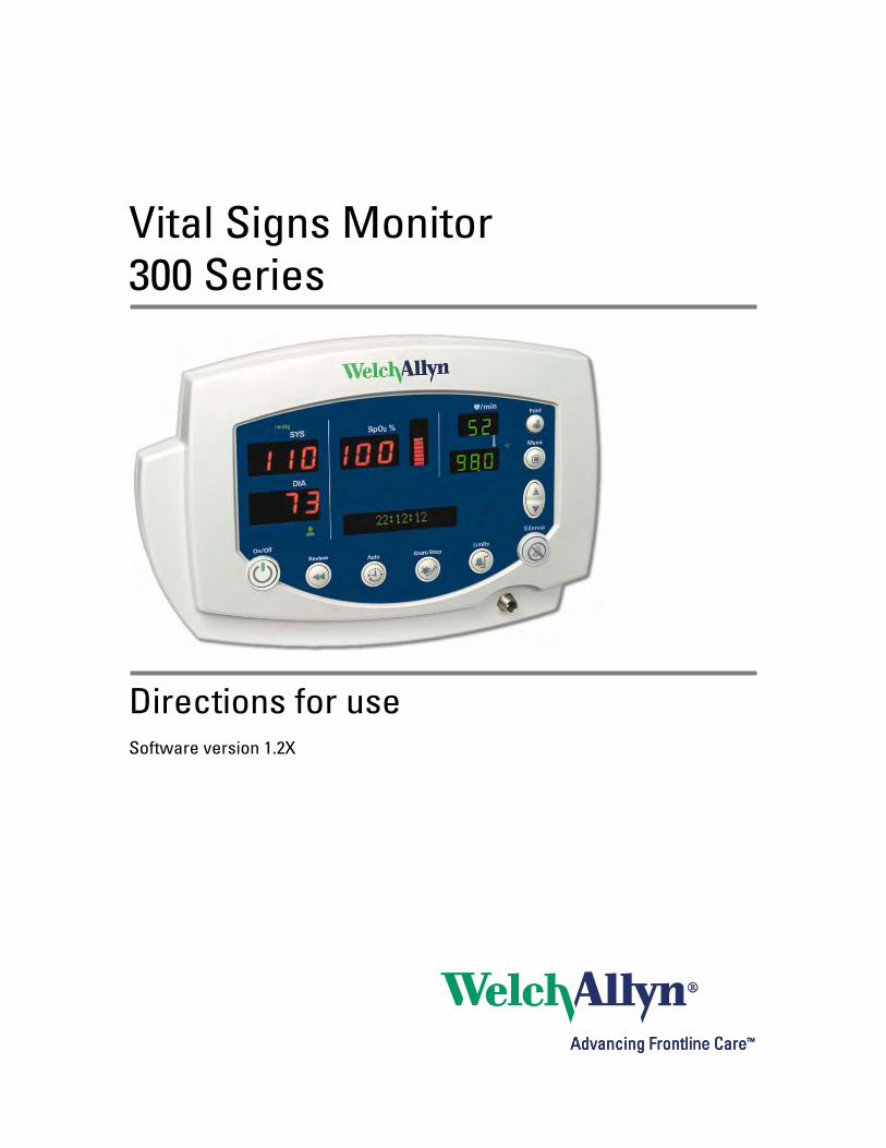
Vital Signs Monitor300 Series
Directions for useSoftware version 1.2X
ii Welch Allyn Vital Signs Monitor 300 Series
© 2014 Welch Allyn. All rights are reserved. To support the intended use of the product described in thispublication, the purchaser of the product is permitted to copy this publication, for internal distribution only,from the media provided by Welch Allyn.
Welch Allyn assumes no responsibility for any injury to anyone, or for any illegal or improper use of theproduct, that may result from failure to use this product in accordance with the instructions, cautions,warnings, or statement of intended use published in this manual.
Welch Allyn is a registered trademark of Welch Allyn.
Nellcor is a registered trademark of Nellcor Puritan Bennett Inc.
Software in this product is copyright Welch Allyn or its vendors. All rights are reserved. The software isprotected by United States of America copyright laws and international treaty provisions applicableworldwide. Under such laws, the licensee is entitled to use the copy of the software incorporated withthis instrument as intended in the operation of the product in which it is embedded. The software may notbe copied, decompiled, reverse-engineered, disassembled or otherwise reduced to human-perceivableform. This is not a sale of the software or any copy of the software; all right, title and ownership of thesoftware remains with Welch Allyn or its vendors.
For information about any Welch Allyn product, visit www.welchallyn.com/en/about-us/locations.html.
DIR 80019418 Ver A
www.welchallyn.com
Welch Allyn Protocol Inc.8500 SW Creekside PlaceBeaverton, OR 97008USA
Regulatory Affairs RepresentativeWelch Allyn LimitedNavan Business ParkDublin Road, NavanCounty Meath, Republic of Ireland
iii
Contents1 - General Information . . . . . . . . . . . . . . . . . . . . . . . . . . . . . . . . . . . . . . 1
About This Manual . . . . . . . . . . . . . . . . . . . . . . . . . . . . . . . . . . . . . . . . . . . . . . . . 1Intended Use . . . . . . . . . . . . . . . . . . . . . . . . . . . . . . . . . . . . . . . . . . . . . . . . . . . . 1Symbols . . . . . . . . . . . . . . . . . . . . . . . . . . . . . . . . . . . . . . . . . . . . . . . . . . . . . . . . 2Product Overview. . . . . . . . . . . . . . . . . . . . . . . . . . . . . . . . . . . . . . . . . . . . . . . . . 3Warnings and Cautions. . . . . . . . . . . . . . . . . . . . . . . . . . . . . . . . . . . . . . . . . . . . . 4Displays, Indicators, Controls, and Connections. . . . . . . . . . . . . . . . . . . . . . . . . . 6
2 - Setup . . . . . . . . . . . . . . . . . . . . . . . . . . . . . . . . . . . . . . . . . . . . . . . . . . 9Connections . . . . . . . . . . . . . . . . . . . . . . . . . . . . . . . . . . . . . . . . . . . . . . . . . . . . . 9Power On, Power-on Self-Test, and Power Off . . . . . . . . . . . . . . . . . . . . . . . . . 15Configuring Operating Parameters . . . . . . . . . . . . . . . . . . . . . . . . . . . . . . . . . . . 16
3 - Patient Monitoring . . . . . . . . . . . . . . . . . . . . . . . . . . . . . . . . . . . . . . 29Monitoring Blood Pressure . . . . . . . . . . . . . . . . . . . . . . . . . . . . . . . . . . . . . . . . . 29Monitoring Pulse Rate . . . . . . . . . . . . . . . . . . . . . . . . . . . . . . . . . . . . . . . . . . . . 36Monitoring SpO2. . . . . . . . . . . . . . . . . . . . . . . . . . . . . . . . . . . . . . . . . . . . . . . . . 37Monitoring Temperature. . . . . . . . . . . . . . . . . . . . . . . . . . . . . . . . . . . . . . . . . . . 40
4 - Alarms and Alerts . . . . . . . . . . . . . . . . . . . . . . . . . . . . . . . . . . . . . . . 51Responding to a Patient Alarm . . . . . . . . . . . . . . . . . . . . . . . . . . . . . . . . . . . . . . 51Responding to an Equipment Alert. . . . . . . . . . . . . . . . . . . . . . . . . . . . . . . . . . . 52Alarm Indicators . . . . . . . . . . . . . . . . . . . . . . . . . . . . . . . . . . . . . . . . . . . . . . . . . 54Setting Alarms . . . . . . . . . . . . . . . . . . . . . . . . . . . . . . . . . . . . . . . . . . . . . . . . . . 54Nurse Call . . . . . . . . . . . . . . . . . . . . . . . . . . . . . . . . . . . . . . . . . . . . . . . . . . . . . . 57Error Codes. . . . . . . . . . . . . . . . . . . . . . . . . . . . . . . . . . . . . . . . . . . . . . . . . . . . . 58
5 - Reviewing Patient Data. . . . . . . . . . . . . . . . . . . . . . . . . . . . . . . . . . . 59Displaying Stored Patient Data . . . . . . . . . . . . . . . . . . . . . . . . . . . . . . . . . . . . . . 59Printing Patient Data . . . . . . . . . . . . . . . . . . . . . . . . . . . . . . . . . . . . . . . . . . . . . . 59Erasing Patient Data . . . . . . . . . . . . . . . . . . . . . . . . . . . . . . . . . . . . . . . . . . . . . . 65Replacing the Printer Paper Supply . . . . . . . . . . . . . . . . . . . . . . . . . . . . . . . . . . 66
6 - Operator Maintenance . . . . . . . . . . . . . . . . . . . . . . . . . . . . . . . . . . . 67Cleaning . . . . . . . . . . . . . . . . . . . . . . . . . . . . . . . . . . . . . . . . . . . . . . . . . . . . . . . 67Storage . . . . . . . . . . . . . . . . . . . . . . . . . . . . . . . . . . . . . . . . . . . . . . . . . . . . . . . . 67Recycling Monitor Components . . . . . . . . . . . . . . . . . . . . . . . . . . . . . . . . . . . . . 68

iv Contents Welch Allyn Vital Signs Monitor 300 Series
7 - Reference . . . . . . . . . . . . . . . . . . . . . . . . . . . . . . . . . . . . . . . . . . . . . . 69Battery Operation . . . . . . . . . . . . . . . . . . . . . . . . . . . . . . . . . . . . . . . . . . . . . . . . 69Monitor Specifications . . . . . . . . . . . . . . . . . . . . . . . . . . . . . . . . . . . . . . . . . . . . 71Factory Default Settings . . . . . . . . . . . . . . . . . . . . . . . . . . . . . . . . . . . . . . . . . . . 80
Limited Warranty . . . . . . . . . . . . . . . . . . . . . . . . . . . . . . . . . . . . . . . . . . 81
Index . . . . . . . . . . . . . . . . . . . . . . . . . . . . . . . . . . . . . . . . . . . . . . . . . . . . 83

1
1
General Information
About This ManualThis manual contains information about the Welch Allyn® Vital Signs Monitor 300 Seriesmonitor. The series includes the following models:
All operators must read and understand this manual before using the monitor.
All technicians and other service personnel must read and understand this manual beforeattempting to set up, configure, troubleshoot, or service the monitor.
All information in this manual, including the illustrations, is based on a monitor configuredwith the Temperature, SpO2, and Printer options. If your monitor configuration lacks anyof these options, then some information in this manual does not apply.
Intended UseThe VSM series of monitors are intended to be used by clinicians and medically qualifiedpersonnel for monitoring of noninvasive blood pressure, pulse rate, body temperature,noninvasive functional oxygen saturation of arteriolar hemoglobin (SpO2), and bodytemperature in normal and axillary modes of neonatal, pediatric and adult patients.
The most likely locations for patients to be monitored are general med/surg. floors,general hospital and alternate care environments. This device is available for sale onlyupon the order of a physician or licensed health care professional.
Model Features Model Features
53000 Standard (NIBP, Pulse Rate, and MAP) 53N00 Standard + Nellcor® SpO2
5300P Standard + Printer 53NT0 Standard + Nellcor SpO2 + Temperature
530T0 Standard + Temperature 53N0P Standard + Nellcor SpO2 + Printer
530TP Standard + Temperature + Printer 53NTP Standard + Nellcor SpO2 + Temperature + Printer
2 Chapter 1 General Information Welch Allyn Vital Signs Monitor 300 Series
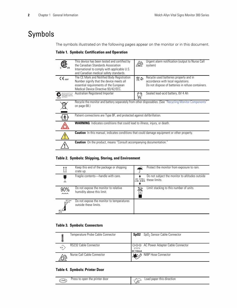
SymbolsThe symbols illustrated on the following pages appear on the monitor or in this document.
Table 1. Symbols: Certification and Operation
Table 2. Symbols: Shipping, Storing, and Environment
Table 3. Symbols: Connectors
Table 4. Symbols: Printer Door
This device has been tested and certified bythe Canadian Standards AssociationInternational to comply with applicable U.S.and Canadian medical safety standards.
Urgent alarm notification (output to Nurse Callsystem)
The CE Mark and Notified Body RegistrationNumber signify that the device meets allessential requirements of the EuropeanMedical Device Directive 93/42/EEC.
Recycle used batteries properly and inaccordance with local regulations.Do not dispose of batteries in refuse containers.
Australian Registered Importer Sealed lead-acid battery, 6V 4 Ah
Recycle the monitor and battery separately from other disposables. (See “Recycling Monitor Components”on page 68.)
Patient connections are Type BF, and protected against defibrillation.
WARNING Indicates conditions that could lead to illness, injury, or death.
Caution In this manual, indicates conditions that could damage equipment or other property.
Caution On the product, means “Consult accompanying documentation.”
Keep this end of the package or shippingcrate up.
Protect the monitor from exposure to rain.
Fragile contents—handle with care. Do not subject the monitor to altitudes outsidethese limits.
Do not expose the monitor to relativehumidity above this limit.
Limit stacking to this number of units.
Do not expose the monitor to temperaturesoutside these limits.
Temperature Probe Cable Connector SpO2 SpO2 Sensor Cable Connector
RS232 Cable Connector AC Power Adapter Cable Connector
Nurse Call Cable Connector NIBP Hose Connector
Press to open the printer door Load paper this direction

Directions for Use Chapter 1 General Information 3
The functions of the monitor front panel controls illustrated here are described in detailelsewhere in this document.
Table 5. Front Panel Controls
Table 6. Front Panel Displays and Indicators
Product OverviewThe monitor can monitor systolic and diastolic noninvasive blood pressure (NIBP), pulserate, and MAP (mean arterial pressure). Units configured with the appropriate options canalso simultaneously monitor temperature and SpO2, and can continuously monitorpulse rate.
All vital-sign measurements are displayed on the front panel of the monitor. Thesemeasurements can also be printed, using the optional integrated thermal printer.
The monitor provides programmable audible and visual alarms and automatic NIBPmeasurements at selectable intervals. It can also be configured to provide an alarm-activated Nurse Call function.
Accessory equipment connected to the analog and digital interfaces must be certified tothe respective IEC standards (IEC 60950 for data-processing equipment, IEC 60601-1 for
Set alarm limits Power on/off
Silence alarms Print patient data
Scroll up/downScroll forward/backIncrease/decrease value
(The scroll icon appears as these two arrowsin the documentation.)
Review patient data
Set an NIBP automatic measurement interval Start/stop an NIBP cycle (AUTO button)
Cycle to the next menu selections
SYSDIA
SpO2
Systolic pressureDiastolic pressureArterial hemoglobin oxygen saturation
Temperature
Pulse rate pulseamplitudeindicator
Pulse strength
messagewindow
MAP (mean arterial pressure) Neonatal
Degrees Celsius Pediatric
Degrees Fahrenheit Adult
Monitored temperature AC powerBattery charging (flashing)Battery charged (steady)
Battery discharged
ºCºC
ºFºF
MM
4 Chapter 1 General Information Welch Allyn Vital Signs Monitor 300 Series
medical equipment). All such configurations must comply with system standardIEC 60601-1-1.
Warnings and CautionsAll operating and service personnel must be familiar with the information presented here,and with other warnings and cautions which appear throughout this document.
Warning and caution labels can appear on the monitor, the packaging, the shippingcontainer, or in this document.
General Warnings
Caution Anyone connecting additional equipment to the signal input part orsignal output part of this monitor configures a medical system and isresponsible for verifying that the system complies with the requirements of thesystem standard IEC 60601-1-1. Changes or modifications not expressly approvedby Welch Allyn could void the purchaser’s authority to operate the equipment.
WARNING Many environmental variables, including patient physiology andclinical application, can affect the accuracy and performance of the device. Theclinician must verify all vital signs information prior to patient intervention.
WARNING The monitor is for use only by medical clinicians. Although thisdocument might illustrate medical monitoring techniques, the monitor must beused only by trained clinicians who know how to take and interpret a patient’svital signs.
WARNING During defibrillation, keep the defibrillation discharge paddles awayfrom any conductive parts that might already be in contact with the patient.
WARNING Use only accessories approved by Welch Allyn. Visitwww.welchallyn.com. The use of any other accessories can result in inaccuratepatient data, can damage the equipment, and can void your product warranty.
WARNING Do not operate the monitor in the presence of magnetic resonanceimaging (MRI) or hyperbaric chambers.
WARNING Do not operate the monitor in the presence of a flammableanesthetic mixture with air, oxygen, or nitrous oxide, or in oxygen-enrichedenvironments, or in any other potentially explosive environment.
WARNING It is the clinician’s responsibility to set or verify alarm limitsappropriate to each patient.
WARNING Never allow any liquid to enter any monitor connector. If a connectordoes come in contact with liquid:
1. Remove the monitor from service.
2. Use warm, dry air to dry the connector.
3. Thoroughly test and verify operation before returning the monitor to service.

Directions for Use Chapter 1 General Information 5
General Cautions
WARNING Do not connect more than one patient to a monitor.
WARNING If the monitor is dropped or damaged, it must be thoroughly testedby a qualified service person before it is returned to service.
WARNING Periodically check all cords and cables for damage, wear, or fraying;replace as needed.
WARNING The monitor contains no operator-serviceable parts, other than thereplaceable paper roll.
WARNING If the battery shows any signs of damage, leakage, or cracking, itmust be replaced immediately, by a qualified service person, and only with abattery approved by Welch Allyn.
WARNING Always recycle batteries according to local regulations. Neverdispose of batteries in refuse containers.
WARNING Do not use the monitor on patients who are linked to a heartmachine or a lung machine.
WARNING Do not use the monitor on patients who are experiencingconvulsions or tremors.
WARNING Do not use the pulse oximeter as a replacement or substitute forECG-based arrhythmia analysis.
Caution If the accuracy of any measurement is in doubt, verify the patient’s vitalsign by another method. If the monitor is not measuring accurately, have itinspected by a qualified service person.
Caution Be sure that the monitor is securely located on a flat surface or properlysuspended by means of appropriate mounting equipment.
Caution Do not autoclave the monitor.
Caution Do not place cups, glasses, or other fluid containers or vessels on themonitor.
Caution Users should check for audible alarm function every time the VSM 300is used. During the normal power-up cycle, two audible tones are emittedimmediately after the self-test is complete. If these tones do not sound, the audiohas failed. Remove the device from service and contact Welch Allyn.
The loss of the audible alarm could cause a delay in a clinician learning of an alarmcondition for the following conditions: 1) hypotension or hypertension, 2) lowblood oxygen content (SpO2), 3) low or high pulse rate, 4) other alarm conditionsrelating to the loss of monitoring of a patient (e.g., a “sensor off” condition). Suchdelay could potentially result in injury to the patient.
6 Chapter 1 General Information Welch Allyn Vital Signs Monitor 300 Series
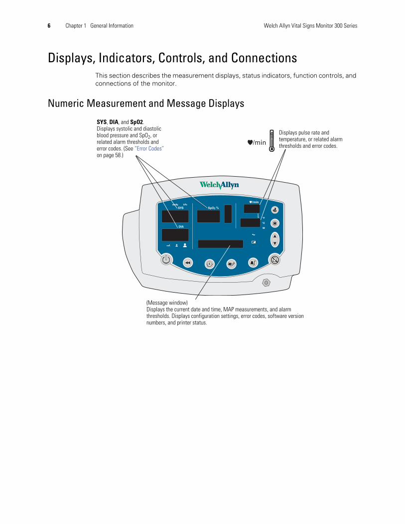
Displays, Indicators, Controls, and ConnectionsThis section describes the measurement displays, status indicators, function controls, andconnections of the monitor.
Numeric Measurement and Message Displays
SYS, DIA, and SpO2.Displays systolic and diastolicblood pressure and SpO2, orrelated alarm thresholds anderror codes. (See “Error Codes”on page 58.)
Displays pulse rate andtemperature, or related alarmthresholds and error codes.
(Message window)Displays the current date and time, MAP measurements, and alarmthresholds. Displays configuration settings, error codes, software versionnumbers, and printer status.
Directions for Use Chapter 1 General Information 7
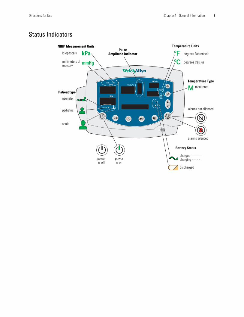
Status Indicators
alarms not silenced
Battery Status
PulseAmplitude Indicator ºFºF
mmHg
kPa
MM
millimeters ofmercury
Patient type
NIBP Measurement Units
kilopascals
neonate
pediatric
adult
degrees Fahrenheit
Temperature Units
degrees CelsiusºCºC
Temperature Type
monitored
charged ———charging - - - - -
discharged
alarms silenced
poweris on
poweris off

8 Chapter 1 General Information Welch Allyn Vital Signs Monitor 300 Series
Function Controls
Connections
For information on the connections, refer to the following:
ReviewData
Set NIBPInterval
Start/Stop NIBP(AUTO button)
Set AlarmLimits
SilenceAlarms
Up/Down
Menu
Poweris off
Poweris on
AlarmsSilenced
Power On/Off
AC Power Adapter “Connecting AC Power” on page 9
Temperature Probe “Connecting the Temperature Probe Cable” on page 12
SpO2 Sensor “Connecting and Disconnecting the SpO2 Sensor Cable” on page 13
NIBP Cuff Hose “Connecting the NIBP Cuff Hose” on page 11
Nurse Call Cable “Nurse Call” on page 79
30V , 1A Max. Temperature ProbeCable Connector
SpO2 Sensor CableConnector
DC Power CableConnector
RS232 CableConnector
Nurse Call CableConnector
SpO2
2
9
SetupThis chapter describes the set-up procedures for patient monitoring.
ConnectionsUse the procedures described below to connect components to the monitor.
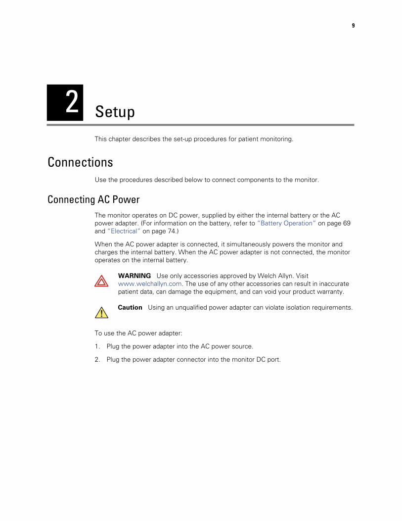
Connecting AC PowerThe monitor operates on DC power, supplied by either the internal battery or the ACpower adapter. (For information on the battery, refer to “Battery Operation” on page 69and “Electrical” on page 74.)
When the AC power adapter is connected, it simultaneously powers the monitor andcharges the internal battery. When the AC power adapter is not connected, the monitoroperates on the internal battery.
To use the AC power adapter:
1. Plug the power adapter into the AC power source.
2. Plug the power adapter connector into the monitor DC port.
WARNING Use only accessories approved by Welch Allyn. Visitwww.welchallyn.com. The use of any other accessories can result in inaccuratepatient data, can damage the equipment, and can void your product warranty.
Caution Using an unqualified power adapter can violate isolation requirements.
10 Chapter 2 Setup Welch Allyn Vital Signs Monitor 300 Series
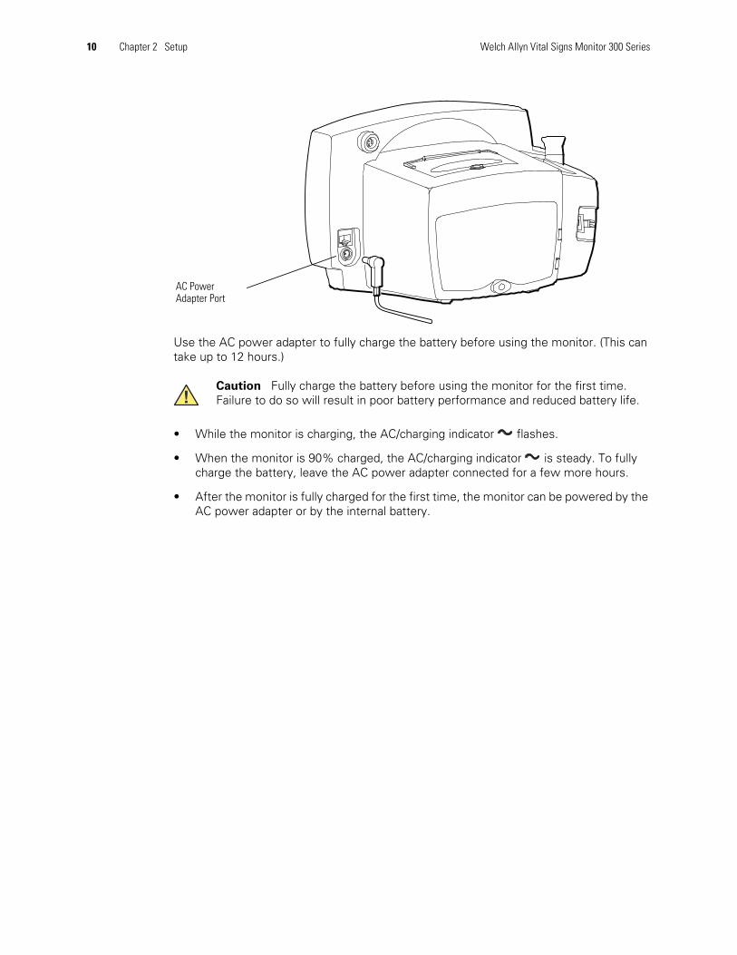
Use the AC power adapter to fully charge the battery before using the monitor. (This cantake up to 12 hours.)
• While the monitor is charging, the AC/charging indicator flashes.
• When the monitor is 90% charged, the AC/charging indicator is steady. To fullycharge the battery, leave the AC power adapter connected for a few more hours.
• After the monitor is fully charged for the first time, the monitor can be powered by theAC power adapter or by the internal battery.
Caution Fully charge the battery before using the monitor for the first time.Failure to do so will result in poor battery performance and reduced battery life.
AC PowerAdapter Port
Directions for Use Chapter 2 Setup 11
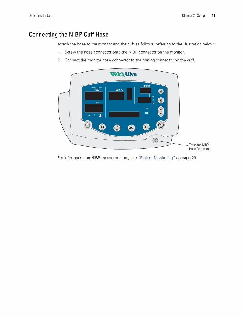
Connecting the NIBP Cuff HoseAttach the hose to the monitor and the cuff as follows, referring to the illustration below:
1. Screw the hose connector onto the NIBP connector on the monitor.
2. Connect the monitor hose connector to the mating connector on the cuff.
For information on NIBP measurements, see “Patient Monitoring” on page 29.
Threaded NIBPHose Connector

12 Chapter 2 Setup Welch Allyn Vital Signs Monitor 300 Series
Connecting the Temperature Probe CableFollow these steps to connect the temperature probe cable to the monitor.
1. Locate the temperature probe connector port on the back of the monitor.
2. Holding the temperature probe cable connector with the spring tab on the right,carefully insert it into the monitor temperature probe connector port. The spring tabclicks out when the connector halves are fully and correctly mated.
3. To disconnect the temperature probe cable, depress the spring tab and withdraw thecable connector.
For information on temperature measurements, see “Patient Monitoring” on page 29.
TemperatureProbeConnector Port
Temperature Probe CableConnector
Directions for Use Chapter 2 Setup 13
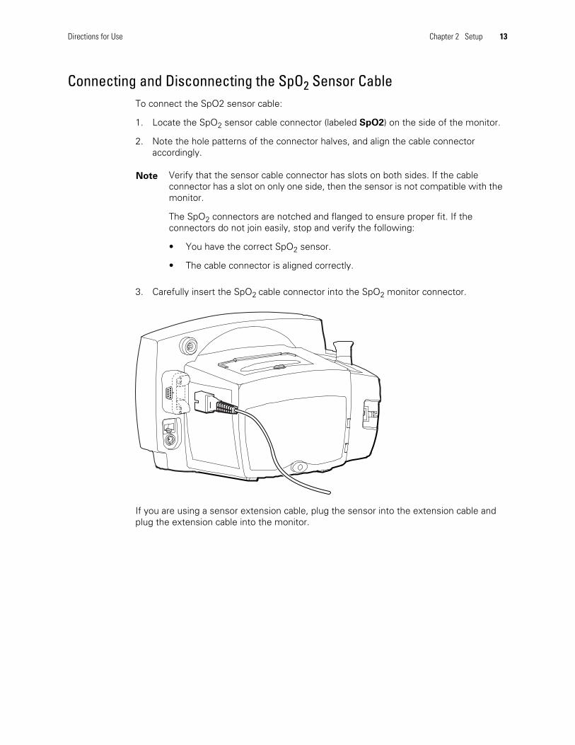
Connecting and Disconnecting the SpO2 Sensor CableTo connect the SpO2 sensor cable:
1. Locate the SpO2 sensor cable connector (labeled SpO2) on the side of the monitor.
2. Note the hole patterns of the connector halves, and align the cable connectoraccordingly.
3. Carefully insert the SpO2 cable connector into the SpO2 monitor connector.
If you are using a sensor extension cable, plug the sensor into the extension cable andplug the extension cable into the monitor.
Note Verify that the sensor cable connector has slots on both sides. If the cableconnector has a slot on only one side, then the sensor is not compatible with themonitor.
The SpO2 connectors are notched and flanged to ensure proper fit. If theconnectors do not join easily, stop and verify the following:
• You have the correct SpO2 sensor.
• The cable connector is aligned correctly.
14 Chapter 2 Setup Welch Allyn Vital Signs Monitor 300 Series
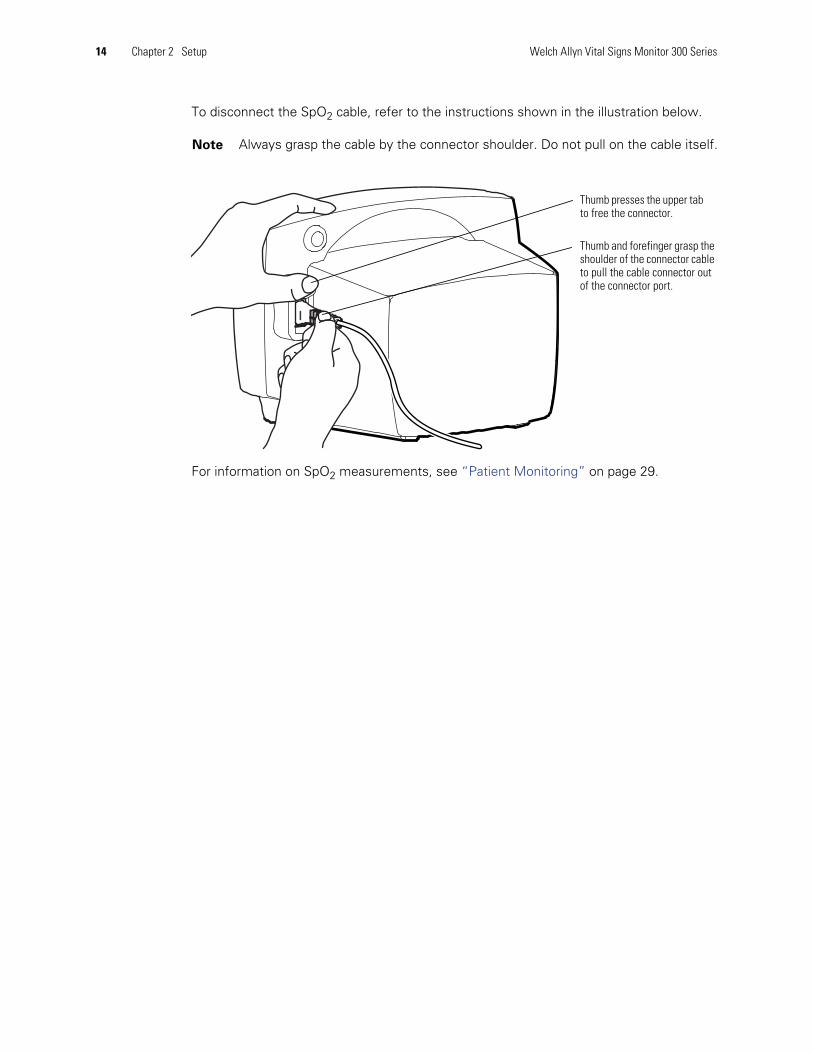
To disconnect the SpO2 cable, refer to the instructions shown in the illustration below.
For information on SpO2 measurements, see “Patient Monitoring” on page 29.
Note Always grasp the cable by the connector shoulder. Do not pull on the cable itself.
Thumb presses the upper tabto free the connector.
Thumb and forefinger grasp theshoulder of the connector cableto pull the cable connector outof the connector port.
Directions for Use Chapter 2 Setup 15
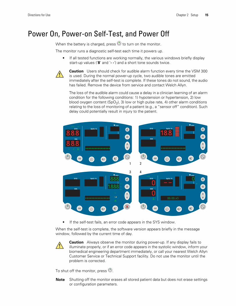
Power On, Power-on Self-Test, and Power OffWhen the battery is charged, press to turn on the monitor.
The monitor runs a diagnostic self-test each time it powers up.
• If all tested functions are working normally, the various windows briefly displaystart-up values (‘8’ and ‘- -’) and a short tone sounds twice.
• If the self-test fails, an error code appears in the SYS window.
When the self-test is complete, the software version appears briefly in the messagewindow, followed by the current time of day.
To shut off the monitor, press .
Caution Users should check for audible alarm function every time the VSM 300is used. During the normal power-up cycle, two audible tones are emittedimmediately after the self-test is complete. If these tones do not sound, the audiohas failed. Remove the device from service and contact Welch Allyn.
The loss of the audible alarm could cause a delay in a clinician learning of an alarmcondition for the following conditions: 1) hypotension or hypertension, 2) lowblood oxygen content (SpO2), 3) low or high pulse rate, 4) other alarm conditionsrelating to the loss of monitoring of a patient (e.g., a “sensor off” condition). Suchdelay could potentially result in injury to the patient.
Caution Always observe the monitor during power-up. If any display fails toilluminate properly, or if an error code appears in the systolic window, inform yourbiomedical engineering department immediately, or call your nearest Welch AllynCustomer Service or Technical Support facility. Do not use the monitor until theproblem is corrected.
Note Shutting off the monitor erases all stored patient data but does not erase settingsor configuration parameters.
SYS
DIA
SpO2 %
/min
ºFºF
mmHg
00
00:00:450
SYS
DIA
SpO2 %
/minmmHg kPa
8.8.8.
****************8.8.8.
SYS
DIA
SpO2 %
/min
****************
18.8.
SYS
DIA
SpO2 %
/min
ºFºF
ºCºC
M
****************
8.8.8.
1.8.8.8.
1 2
3 4

16 Chapter 2 Setup Welch Allyn Vital Signs Monitor 300 Series
Configuring Operating ParametersYou can change several monitor operating parameters. When changed, these settingsbecome the default power-up settings.
How to Use the Menu SystemThe monitor menu system contains three sets of menus—settings, configuration,and service.
Settings Menu
Access the settings menu by pressing the menu button while in normal operation.Then press repeatedly to reach the setting of interest.
5498
37.0128
MAP 90mmHg71
ºFºF ºCºC MM
Patient Type
Target Cuff Inflation Pressure
Temperature UnitsTemperature Type
Pulse Tone Volume
No action for 10 secondsorPress any button other than
Power Off - all values savedexcept target inflation pressure
Settings Menu

Directions for Use Chapter 2 Setup 17
Use the settings menu to select and set the following parameters:
To change a settings parameter:
1. Select the parameter as indicated above.
2. Change the value by pressing or .
3. Set the displayed new value either by doing nothing for 10 seconds or by pressing anybutton other than or . If you press a function button (such as ), the monitorreturns to normal operation with that function ( ) activated.
Patient Type Neonate Term birth through 28 days, or up to 44 gestational weeks
Pediatric 29 days through 12 years
Adult 13 years and older
Target Pressure The initial cuff inflation pressure (set individually for each patient type)
Temp Modes Fahrenheit PredictiveFahrenheit MonitoredCelsius PredictiveCelsius Monitored
Pulse Tone Volume From 0 (silent) to 5 (loudest)
ºFºFºFºF MMºCºCºCºC MM

18 Chapter 2 Setup Welch Allyn Vital Signs Monitor 300 Series
Configuration Menu
The configuration menu is accessed by pressing and keeping it depressed for threeseconds. You then press repeatedly until you reach the setting of interest.
5498
37.0128
MAP 90 kPa71
Set Time and Date
MAP
NIBP Units
PrintNo action for 10 seconds
Power Off - all values saved
Configuration Menu
Press and holdfor 3 seconds
EnableDisable
mmHgkPa
StreamBatch
Press and hold for 3seconds
Press any button other than

Directions for Use Chapter 2 Setup 19
Use the configuration menu to select and set the following parameters:
To change a configuration parameter:
1. Select the parameter as indicated above.
2. Change the value by pressing or .
3. Set the displayed new value either by doing nothing for 10 seconds or by pressing anybutton other than or . If you press a function button (such as ), the monitorreturns to normal operation with that function ( ) activated.
Time and Date hourminuteyearmonthday
MAP Measurement EnabledDisabled
Blood PressureMeasurement Units
mmHg (millimeters of mercury)kPa (kilopascals)
Print Mode BatchStream
20 Chapter 2 Setup Welch Allyn Vital Signs Monitor 300 Series
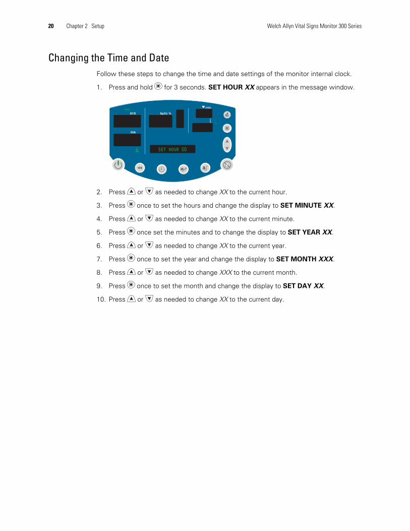
Changing the Time and DateFollow these steps to change the time and date settings of the monitor internal clock.
1. Press and hold for 3 seconds. SET HOUR XX appears in the message window.
2. Press or as needed to change XX to the current hour.
3. Press once to set the hours and change the display to SET MINUTE XX.
4. Press or as needed to change XX to the current minute.
5. Press once set the minutes and to change the display to SET YEAR XX.
6. Press or as needed to change XX to the current year.
7. Press once to set the year and change the display to SET MONTH XXX.
8. Press or as needed to change XXX to the current month.
9. Press once to set the month and change the display to SET DAY XX.
10. Press or as needed to change XX to the current day.
SYS
DIA
SpO2 %
/min
ºFºF
mmHg
SET HOUR 00
Directions for Use Chapter 2 Setup 21
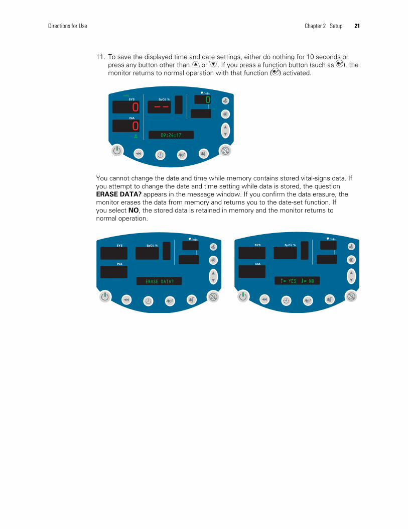
11. To save the displayed time and date settings, either do nothing for 10 seconds orpress any button other than or . If you press a function button (such as ), themonitor returns to normal operation with that function ( ) activated.
You cannot change the date and time while memory contains stored vital-signs data. Ifyou attempt to change the date and time setting while data is stored, the questionERASE DATA? appears in the message window. If you confirm the data erasure, themonitor erases the data from memory and returns you to the date-set function. Ifyou select NO, the stored data is retained in memory and the monitor returns tonormal operation.
SYS
DIA
SpO2 %
/min
ºFºF
mmHg
00
09:24:170
SYS
DIA
SpO2 %
/min
= YES = NO
SYS
DIA
SpO2 %
/min
ERASE DATA?

22 Chapter 2 Setup Welch Allyn Vital Signs Monitor 300 Series
Changing the Patient TypeThe age range for each patient type is defined as follows:
Default setting: ADULT.
Follow these steps to change the patient type setting.
1. Press . The current patient type ( , , or ) appears below the DIA window, andNEONATE, PEDIATRIC, or ADULT appears in the message window.
2. Press or to display , , or .
3. To select the displayed patient type and return to normal operation, either do nothingfor 10 seconds or press any button other than or . If you press a function button(such as ), the monitor returns to normal operation with that function ( ) activated.
Changing the patient type has the following effects:
• Alarm limits are reset to the default limits for the new patient type
• Cuff inflation target pressure is reset to the default for the new patient type
If you cycle through the patient types but do not change the setting, the alarm limits andthe cuff inflation target pressure settings do not change.
Neonatal Term birth through 28 days, or up to 44 gestational weeks
Pediatric 29 days through 12 years
Adult 13 years and older
SYS
DIA
SpO2 %
/min
ºFºF
mmHg
00
ADULT0
SYS
DIA
SpO2 %
/min
ºFºF
mmHg
NEONATE
Directions for Use Chapter 2 Setup 23
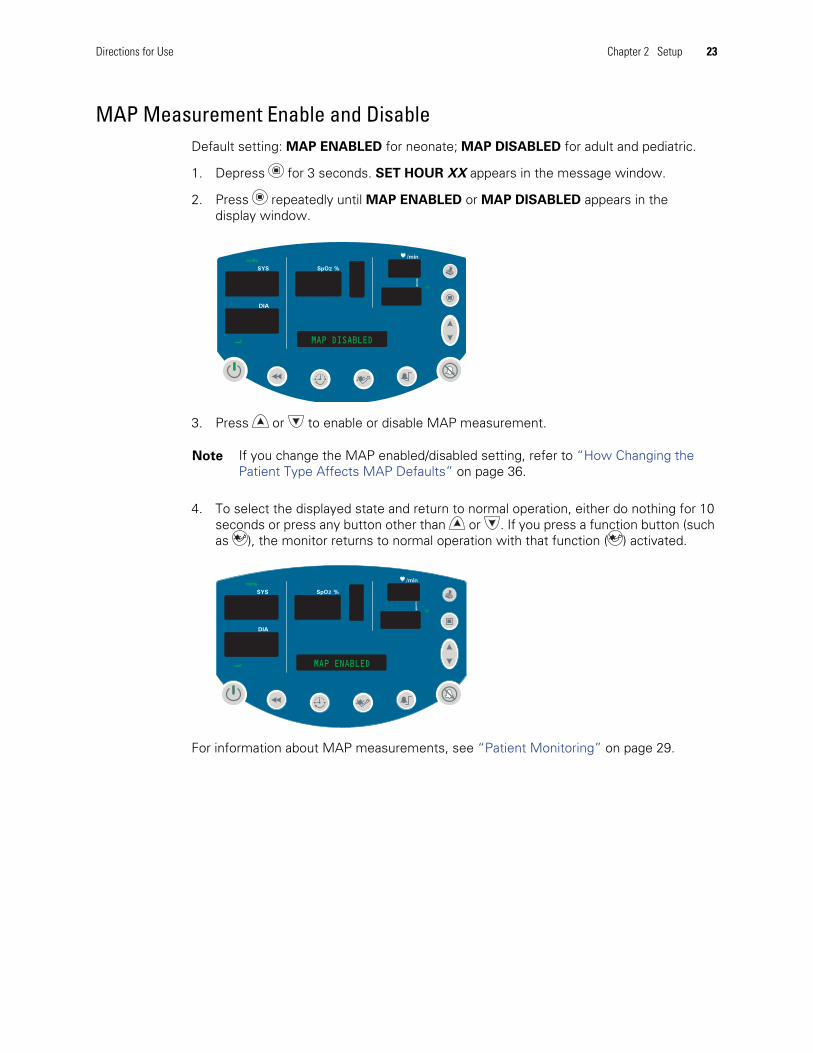
MAP Measurement Enable and DisableDefault setting: MAP ENABLED for neonate; MAP DISABLED for adult and pediatric.
1. Depress for 3 seconds. SET HOUR XX appears in the message window.
2. Press repeatedly until MAP ENABLED or MAP DISABLED appears in thedisplay window.
3. Press or to enable or disable MAP measurement.
4. To select the displayed state and return to normal operation, either do nothing for 10seconds or press any button other than or . If you press a function button (suchas ), the monitor returns to normal operation with that function ( ) activated.
For information about MAP measurements, see “Patient Monitoring” on page 29.
Note If you change the MAP enabled/disabled setting, refer to “How Changing thePatient Type Affects MAP Defaults” on page 36.
SYS
DIA
SpO2 %
/min
ºFºF
mmHg
MAP DISABLED
SYS
DIA
SpO2 %
/min
ºFºF
mmHg
MAP ENABLED

24 Chapter 2 Setup Welch Allyn Vital Signs Monitor 300 Series
Changing the NIBP Measurement UnitsDefault setting: mmHg.
To change the NIBP measurement units:
1. Depress for 3 seconds. SET HOUR XX appears in the message window.
2. Press repeatedly until BP Units: mmHg or BP Units: kPa appears in thedisplay window.
3. Press or as needed to display the desired NIBP measurement units.
4. To select the displayed units and return to normal operation, either do nothing for 10seconds or press any button other than or . If you press a function button (suchas ), the monitor returns to normal operation with that function ( ) activated.
For information on NIBP measurements, see “Patient Monitoring” on page 29.
SYS
DIA
SpO2 %
/min
ºFºF
mmHg
BP Units: mmHg
SYS
DIA
SpO2 %
/min
ºFºF
kPa
BP Units: kPa

Directions for Use Chapter 2 Setup 25
Changing Temperature Type and Measurement UnitsDefault setting: F (Fahrenheit predictive).
To change the temperature type and the temperature measurement units:
1. With the monitor on, press repeatedly until TEMP MODE appears in the displaywindow. One or two green LEDs to the right of the temperature window illuminate toindicate the selected temperature type.
2. Press or as needed to cycle to the desired display:
F (Fahrenheit Predictive)F M (Fahrenheit Monitored)C (Celsius Predictive)C M (Celsius Monitored)
3. To select the displayed units and return to normal operation, either do nothing for 10seconds or press any button other than or . If you press a function button (suchas ), the monitor returns to normal operation with that function ( ) activated.
For information on temperature measurements, see “Patient Monitoring” on page 29.
SYS
DIA
SpO2 %
/minmmHg
ºCºC
M
TEMP MODE
SYS
DIA
SpO2 %
/minmmHg
ºFºF
0
98.6
20:30:1679
119
26 Chapter 2 Setup Welch Allyn Vital Signs Monitor 300 Series
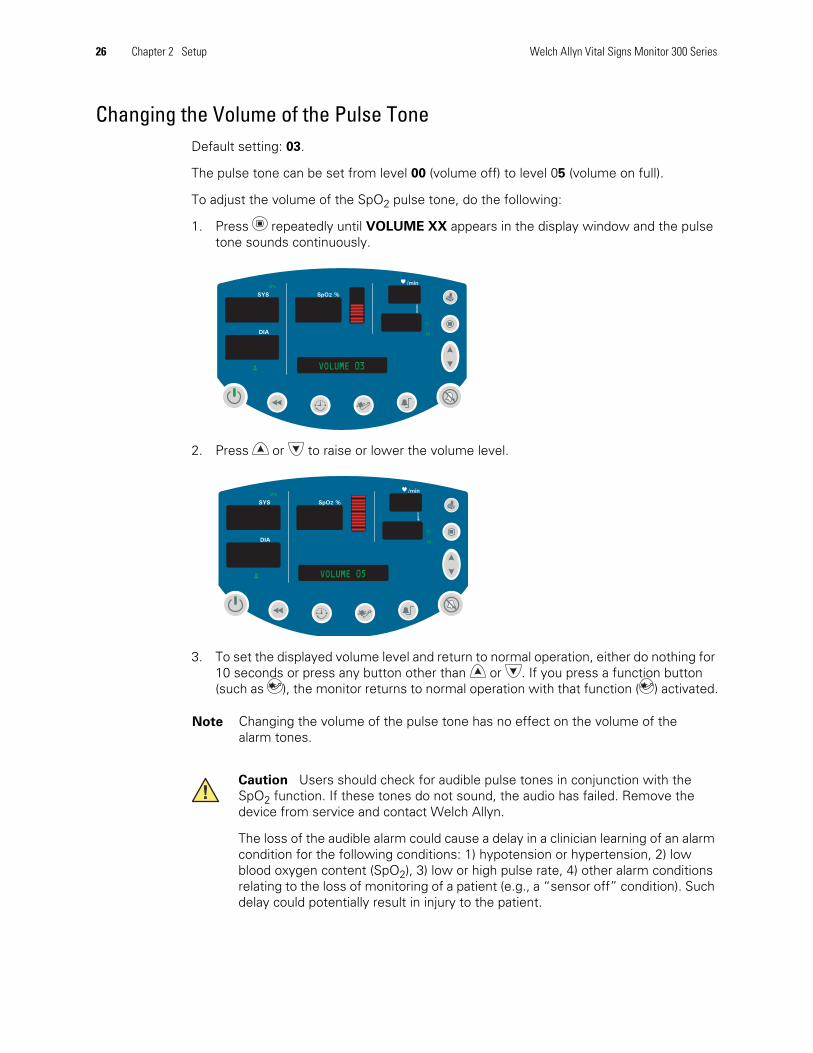
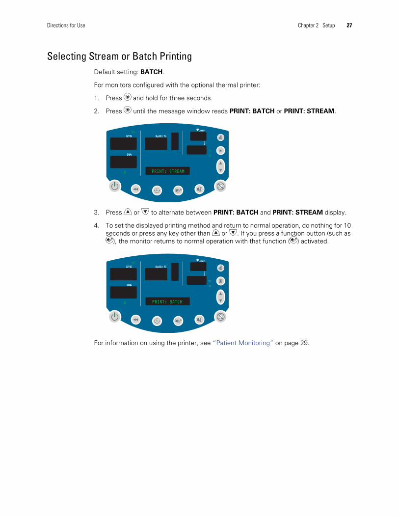
Changing the Volume of the Pulse ToneDefault setting: 03.
The pulse tone can be set from level 00 (volume off) to level 05 (volume on full).
To adjust the volume of the SpO2 pulse tone, do the following:
1. Press repeatedly until VOLUME XX appears in the display window and the pulsetone sounds continuously.
2. Press or to raise or lower the volume level.
3. To set the displayed volume level and return to normal operation, either do nothing for10 seconds or press any button other than or . If you press a function button(such as ), the monitor returns to normal operation with that function ( ) activated.
Note Changing the volume of the pulse tone has no effect on the volume of thealarm tones.
Caution Users should check for audible pulse tones in conjunction with theSpO2 function. If these tones do not sound, the audio has failed. Remove thedevice from service and contact Welch Allyn.
The loss of the audible alarm could cause a delay in a clinician learning of an alarmcondition for the following conditions: 1) hypotension or hypertension, 2) lowblood oxygen content (SpO2), 3) low or high pulse rate, 4) other alarm conditionsrelating to the loss of monitoring of a patient (e.g., a “sensor off” condition). Suchdelay could potentially result in injury to the patient.
SYS
DIA
SpO2 %
/min
ºCºC
M
kPa
VOLUME 03
SYS
DIA
SpO2 %
/min
ºCºC
M
kPa
VOLUME 05
Directions for Use Chapter 2 Setup 27
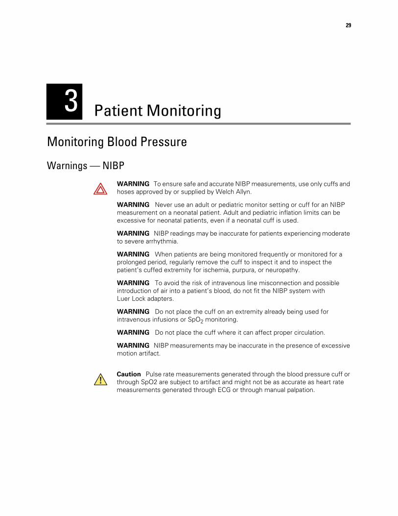
Selecting Stream or Batch PrintingDefault setting: BATCH.
For monitors configured with the optional thermal printer:
1. Press and hold for three seconds.
2. Press until the message window reads PRINT: BATCH or PRINT: STREAM.
3. Press or to alternate between PRINT: BATCH and PRINT: STREAM display.
4. To set the displayed printing method and return to normal operation, do nothing for 10seconds or press any key other than or . If you press a function button (such as
), the monitor returns to normal operation with that function ( ) activated.
For information on using the printer, see “Patient Monitoring” on page 29.
SYS
DIA
SpO2 %
/min
ºCºC
M
kPa
PRINT: STREAM
SYS
DIA
SpO2 %
/min
ºCºC
M
kPa
PRINT: BATCH

28 Chapter 2 Setup Welch Allyn Vital Signs Monitor 300 Series
3
29
Patient Monitoring
Monitoring Blood Pressure
Warnings — NIBP
WARNING To ensure safe and accurate NIBP measurements, use only cuffs andhoses approved by or supplied by Welch Allyn.
WARNING Never use an adult or pediatric monitor setting or cuff for an NIBPmeasurement on a neonatal patient. Adult and pediatric inflation limits can beexcessive for neonatal patients, even if a neonatal cuff is used.
WARNING NIBP readings may be inaccurate for patients experiencing moderateto severe arrhythmia.
WARNING When patients are being monitored frequently or monitored for aprolonged period, regularly remove the cuff to inspect it and to inspect thepatient’s cuffed extremity for ischemia, purpura, or neuropathy.
WARNING To avoid the risk of intravenous line misconnection and possibleintroduction of air into a patient’s blood, do not fit the NIBP system withLuer Lock adapters.
WARNING Do not place the cuff on an extremity already being used forintravenous infusions or SpO2 monitoring.
WARNING Do not place the cuff where it can affect proper circulation.
WARNING NIBP measurements may be inaccurate in the presence of excessivemotion artifact.
Caution Pulse rate measurements generated through the blood pressure cuff orthrough SpO2 are subject to artifact and might not be as accurate as heart ratemeasurements generated through ECG or through manual palpation.

30 Chapter 3 Patient Monitoring Welch Allyn Vital Signs Monitor 300 Series
NIBP PreparationBefore you start any NIBP measurement, always follow the steps described inthese procedures:
• “Changing the Target Pressure” on page 30
• “If the following actions and conditions occur in sequence, monitor behavior is asfollows, which differs from what is described in “Changing the Target Pressure” .”on page 30
• “Positioning the Cuff” on page 31
Changing the Target Pressure
Follow these steps to change the target pressure (default initial pressure for cuff inflation)for the current patient type:
1. Press until the message window displays TARGET PRESSURE.
The SYS window displays the current setting for initial inflation pressure.
2. Press or to raise or lower the preset pressure value to the target level.
To set the displayed pressure level and return to normal operation, either do nothingfor 10 seconds or press any button other than or . If you press a function button(such as ), the monitor returns to normal operation with that function ( ) activated.
If the following actions and conditions occur in sequence, monitor behavior is as follows,which differs from what is described in “Changing the Target Pressure” .
Action 1. You select a nondefault target pressure.
Action 2. You start an NIBP measurement.
Condition 1. The pump reaches the target pressure and the pressure starts tobleed off.
Condition 2. The pressure bleed-off is interrupted (motion artifact or NIBPstart/stop button press) and the measurement cycle does not complete.
Action 3. You select the default target pressure.
Action 4. You restart the NIBP measurement.
Under these conditions, the monitor does not use the default target pressure; instead, ituses the target pressure set in Action 1 above.
• Following a successful NIBP measurement, the monitor adjusts subsequent NIBPattempts to pump up to the lowest target that works.
• Following an unsuccessful measurement, however, the monitor increases targetpressure and then pumps up for one, two, or three attempts before it stops.
Note Target pressure is a nominal starting point. If it is too low to take a measurement,the monitor takes another measurement using a higher initial pressure.

Directions for Use Chapter 3 Patient Monitoring 31
If Action 1 and Action 2 lead to Condition 1 and Condition 2, do the following to restorethe monitor to normal operation:
1. Power the monitor off.
2. Power the monitor on.
Start the blood-pressure measurement using the default target pressure.
Selecting a Cuff
You can tell whether the cuff size is appropriate by putting the cuff on the patient and theninspecting the fit. If the edge marking lies somewhere between the two range markings,then the fit is correct.
You can also find the correct cuff by measuring the circumference of the patient’s arm atthe biceps:
Positioning the Cuff
For the most accurate measurement, do the following:
1. Position the cuff on the bare arm, midway between the shoulder and the elbow.
Typical cuff positions are shown in this illustration:
2. Position the alignment mark on the cuff directly over the brachial artery.
Cuff Size Circumference(inches)
Circumference(centimeters)
Cuff Size Circumference(inches)
Circumference(centimeters)
Neonate #1 1.3 - 2.2 3.3 - 5.6 Small Child 4.9 - 6.6 12.4 - 16.8
Neonate #2 1.6 - 2.8 4.2 - 7.1 Child 6.2 - 8.4 15.8 - 21.3
Neonate #3 2.1 - 3.6 5.4 - 9.1 Small Adult 7.9 - 10.6 20.0 - 27.0
Neonate #4 2.4 - 4.6 6.9 - 11.7 Adult 10.0 - 13.5 25.3 - 34.4
Neonate #5 3.5 - 5.9 8.9 - 15.0 Large Adult 12.6 - 17.1 32.1 - 43.4
Infant 3.9 - 5.2 9.8 - 13.3 Thigh 16.0 - 21.7 40.7 - 55.0
Adult and Pediatric
Neonatal
32 Chapter 3 Patient Monitoring Welch Allyn Vital Signs Monitor 300 Series
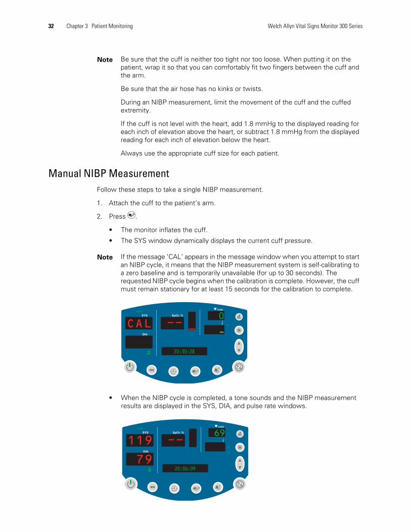
Manual NIBP MeasurementFollow these steps to take a single NIBP measurement.
1. Attach the cuff to the patient’s arm.
2. Press .
• The monitor inflates the cuff.
• The SYS window dynamically displays the current cuff pressure.
• When the NIBP cycle is completed, a tone sounds and the NIBP measurementresults are displayed in the SYS, DIA, and pulse rate windows.
Note Be sure that the cuff is neither too tight nor too loose. When putting it on thepatient, wrap it so that you can comfortably fit two fingers between the cuff andthe arm.
Be sure that the air hose has no kinks or twists.
During an NIBP measurement, limit the movement of the cuff and the cuffedextremity.
If the cuff is not level with the heart, add 1.8 mmHg to the displayed reading foreach inch of elevation above the heart, or subtract 1.8 mmHg from the displayedreading for each inch of elevation below the heart.
Always use the appropriate cuff size for each patient.
Note If the message ‘CAL’ appears in the message window when you attempt to startan NIBP cycle, it means that the NIBP measurement system is self-calibrating toa zero baseline and is temporarily unavailable (for up to 30 seconds). Therequested NIBP cycle begins when the calibration is complete. However, the cuffmust remain stationary for at least 15 seconds for the calibration to complete.
SYS
DIA
SpO2 %
/minmmHg
ºFºF
0
20:30:28
CAL
SYS
DIA
SpO2 %
/minmmHg
ºCºC
M
69
20:06:0979
119
Directions for Use Chapter 3 Patient Monitoring 33
• If MAP is enabled, MAP results are displayed in the message window.
The measurement display persists for two minutes or until another NIBP cycle isinitiated. If an error is detected, an error tone sounds and an error code appears inthe SYS window.
Automatic NIBP MeasurementAutomatic NIBP measurements repeat continuously at programmed intervals.
To set up an automatic NIBP measurement, do the following:
1. Attach the cuff to the patient’s arm.
2. Press to set the measurement interval.
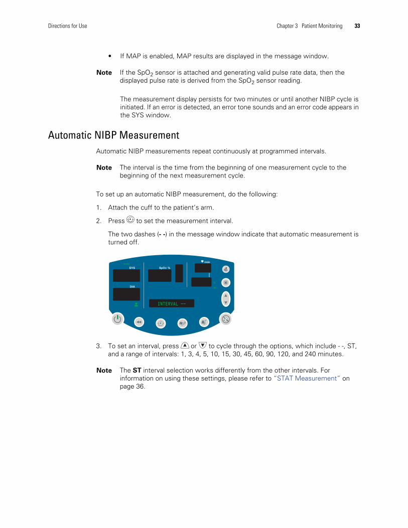
The two dashes (- -) in the message window indicate that automatic measurement isturned off.
3. To set an interval, press or to cycle through the options, which include - -, ST,and a range of intervals: 1, 3, 4, 5, 10, 15, 30, 45, 60, 90, 120, and 240 minutes.
Note If the SpO2 sensor is attached and generating valid pulse rate data, then thedisplayed pulse rate is derived from the SpO2 sensor reading.
Note The interval is the time from the beginning of one measurement cycle to thebeginning of the next measurement cycle.
Note The ST interval selection works differently from the other intervals. Forinformation on using these settings, please refer to “STAT Measurement” onpage 36.
SYS
DIA
SpO2 %
/minmmHg
ºCºC
M
INTERVAL --
34 Chapter 3 Patient Monitoring Welch Allyn Vital Signs Monitor 300 Series
4. To select the currently displayed interval, press any button other than , or .
Ten seconds after you select an interval, and assuming that safe venous returnpressure (SVRP) has been maintained for at least 30 seconds, the monitor starts thefirst automatic NIBP cycle and the following occurs:
• The cuff inflates to the default pressure level.
• The SYS window dynamically displays the current cuff pressure.
• If MAP is enabled, the MAP measurement value alternates with the time displayin the message window.
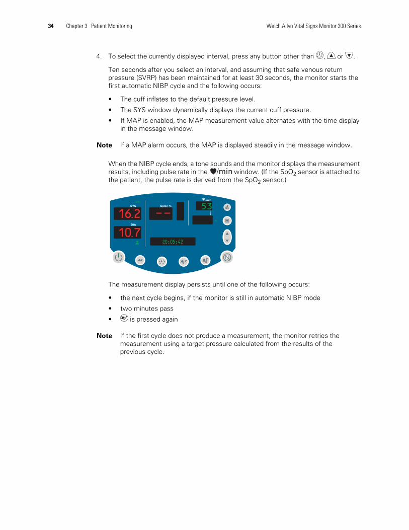
When the NIBP cycle ends, a tone sounds and the monitor displays the measurementresults, including pulse rate in the window. (If the SpO2 sensor is attached tothe patient, the pulse rate is derived from the SpO2 sensor.)
The measurement display persists until one of the following occurs:
• the next cycle begins, if the monitor is still in automatic NIBP mode
• two minutes pass
• is pressed again
Note If a MAP alarm occurs, the MAP is displayed steadily in the message window.
Note If the first cycle does not produce a measurement, the monitor retries themeasurement using a target pressure calculated from the results of theprevious cycle.
SYS
DIA
SpO2 %
/minkPa
ºCºC
16.2
10.7
53
20:05:42

Directions for Use Chapter 3 Patient Monitoring 35
The automatic NIBP cycles continue until one of the following occurs:
• The monitor reaches the 5-minute limit for a STAT measurement. (The currentcycle continues to completion, even if it goes beyond the 5-minute limit.)
• The monitor halts because is pressed.
• The monitor halts because of an alarm, alert, or error condition.
• The interval code is changed to ‘- -’.
If an error is detected during the measurement, an error tone sounds and an error codeappears in the SYS window.
MAP Measurement
MAP is available for adult, pediatric, and neonatal patients. The monitor is set at thefactory to enable MAP display and alarm limit checking for neonatal patients, and todisable those functions for adult and pediatric patients.
If MAP is enabled, the monitor displays MAP readings in the message window at the endof NIBP measurements.
Note The latest NIBP measurement is displayed until one of the following occurs:
• the next NIBP cycle starts
• an alarm, alert, or error occurs
• the monitor shuts down
SYS
DIA
SpO2 %
/min
ºCºC
kPa
122
MAP 7.5 kPa6.0
10.7 9837.2
36 Chapter 3 Patient Monitoring Welch Allyn Vital Signs Monitor 300 Series
How Changing the Patient Type Affects MAP Defaults
When you cycle power to the monitor, the monitor stores all current settings beforeshutting down. It then uses these saved settings when it powers up again. (This does notaffect the factory default settings.)
Whenever you enable or disable MAP for a given patient type—Adult, Pediatric,Neonatal—the current enabled/disabled setting becomes the default power-up setting forthat patient type.
For example: If the monitor is set to Neonatal and you set MAP Disabled, MAP Disabledbecomes the default setting for neonatal patients until you change the enabled/disabledsetting again.
Enabling and Disabling MAP Measurement
See “MAP Measurement Enable and Disable” on page 23.
STAT Measurement
If the selected interval is STAT, the monitor takes repeated NIBP measurements for 5minutes, starting a new cycle each time the cuff deflates below safe venous returnpressure (SVRP) for two seconds.
Current cuff pressures are not dynamically displayed during a STAT reading. The messagewindow displays the NIBP reading from the previous cycle until the current cycle finishes.(Before the first cycle finishes, the display reads ‘0.’)
Monitoring Pulse RateThe monitor displays the pulse rate at the end of all NIBP or SpO2 measurements. Itdisplays NIBP pulse information only if no SpO2 reading is available.
If the SpO2 sensor is connected to the patient during the measurement period, the pulseamplitude indicator rises and falls in rhythm with the monitored heart rate. The higher thedisplay rises, the stronger the measured pulse; however, the height of the indicatordisplay is not mathematically proportional to the volume of the pulse.
Directions for Use Chapter 3 Patient Monitoring 37
Monitoring SpO2
Warnings and Cautions — SpO2
WARNING Always follow the manufacturer’s instructions for care and use of theSpO2 sensor.
WARNING The accuracy of the SpO2 measurement can be affected by any ofthe following:
• the presence of significant amounts of dysfunctional hemoglobin, such ascarboxyhemoglobin or methemoglobin
• the presence of concentrations of some intravascular dyes, sufficient tochange the patient’s usual arterial pigmentation
• patient movement
• patient conditions such as shivering and smoke inhalation
• painted nails
• poor oxygen perfusion
• anemia or low concentrations of hemoglobin
• hypotension or hypertension
• severe vasoconstriction
• shock or cardiac arrest
• venous pulsations or sudden and significant changes in pulse rate
• proximity to an MRI environment
• moisture in the sensor
• excessive ambient light, especially fluorescent
• wrong sensor or sensor too tight
WARNING If there is any question of the accuracy of an SpO2 measurement,verify the measurement using another clinically accepted measurement method.

38 Chapter 3 Patient Monitoring Welch Allyn Vital Signs Monitor 300 Series
SpO2 Monitoring Procedure1. Verify that the SpO2 sensor cable is connected to the monitor.
2. Attach the SpO2 finger clip sensor to the end of the patient’s index finger, as shownbelow. The sensor can be attached to the patient when the monitor is on or off, andduring an NIBP cycle.
WARNING Do not use the SpO2 sensor as an apnea monitor.
WARNING During prolonged, continuous SpO2 monitoring, check the sensorsite often, in compliance with the sensor manufacturer’s directions. Inspect thepatient’s skin integrity and circulation, and relocate the sensor if necessary.Tissue damage can result from improper or prolonged sensor attachment.
• Use only sensors and accessories recommended by Welch Allyn.
• Do not use damaged sensors or cables.
• Do not use a sensor with exposed optical components.
• Do not immerse or wet the sensor.
Caution Some sensors might not work with some patients. If, after 20 seconds,a properly functioning sensor fails to discern a pulse, do the following:
1. Adjust or reposition the sensor. If the failure continues:
2. Use a different type of sensor.
WARNING Do not use an SpO2 finger clip sensor and a blood pressure cuffsimultaneously on the same limb. To do so will result in inaccurate pulse rate andperfusion readings, and could cause erroneous pulse rate alarms.
Directions for Use Chapter 3 Patient Monitoring 39
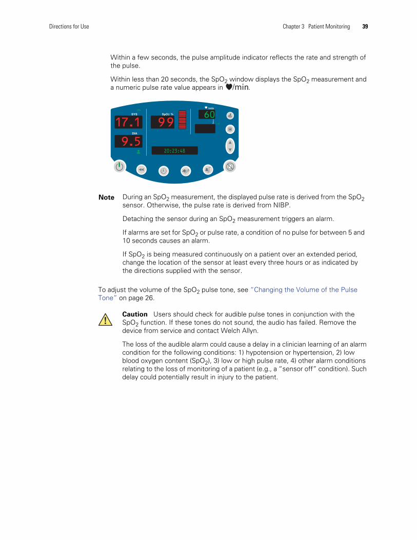
Within a few seconds, the pulse amplitude indicator reflects the rate and strength ofthe pulse.
Within less than 20 seconds, the SpO2 window displays the SpO2 measurement anda numeric pulse rate value appears in .
To adjust the volume of the SpO2 pulse tone, see “Changing the Volume of the PulseTone” on page 26.
Note During an SpO2 measurement, the displayed pulse rate is derived from the SpO2sensor. Otherwise, the pulse rate is derived from NIBP.
Detaching the sensor during an SpO2 measurement triggers an alarm.
If alarms are set for SpO2 or pulse rate, a condition of no pulse for between 5 and10 seconds causes an alarm.
If SpO2 is being measured continuously on a patient over an extended period,change the location of the sensor at least every three hours or as indicated bythe directions supplied with the sensor.
Caution Users should check for audible pulse tones in conjunction with theSpO2 function. If these tones do not sound, the audio has failed. Remove thedevice from service and contact Welch Allyn.
The loss of the audible alarm could cause a delay in a clinician learning of an alarmcondition for the following conditions: 1) hypotension or hypertension, 2) lowblood oxygen content (SpO2), 3) low or high pulse rate, 4) other alarm conditionsrelating to the loss of monitoring of a patient (e.g., a “sensor off” condition). Suchdelay could potentially result in injury to the patient.
SYS
DIA
SpO2 %
/min
ºFºF
kPa
60
20:23:489.5
17.1 99
40 Chapter 3 Patient Monitoring Welch Allyn Vital Signs Monitor 300 Series
Monitoring Temperature
Warnings and Cautions — Temperature
WARNING To ensure patient safety and to obtain accurate and reliabletemperature results, read this section thoroughly before using thetemperature instrument.
WARNING Always put a single-use probe tip cover on the probe tip beforetaking a temperature measurement. Failure to use a probe tip cover cancause patient discomfort, patient cross-contamination, and erroneoustemperature readings.
WARNING Use only Welch Allyn single-use disposable probe covers. The use ofany other probe cover can cause patient cross-contamination and erroneoustemperature readings.
WARNING Never re-use a probe cover.
WARNING Using a probe at the wrong site produces inaccurate measurementsand can cause patient injury.
• Use only oral probes, identified by a blue ejection button at the top of theprobe, to take oral and axillary temperatures.
• Use only rectal probes, identified by a red ejection button at the top of theprobe, to take rectal temperatures.
WARNING Use only the oral probe well with the oral probe, and use only therectal probe well with the rectal probe. Using the wrong probe well can result inpatient cross-contamination.
WARNING Always verify direct probe-cover-to-skin contact. Do not take anaxillary temperature through the patient’s clothing.
WARNING Use extreme caution when taking rectal temperatures on children.Insert the probe tip only 3/8-inch (~1 cm) to avoid risk of bowel perforation.
WARNING The thermometer case is not waterproof. Do not immerse it in fluidsor drip fluids onto it.
WARNING The thermometer consists of high-quality precision parts. Protect itfrom severe impact or shock. Do not use the thermometer if you notice any signsof damage to the probe or the instrument. If the thermometer probe is droppedor damaged, remove it from service and have it inspected by a qualifiedservice person.
WARNING Do not use the thermometer for any purpose other than thosedescribed in this document. Doing so will invalidate the product warranty.
Directions for Use Chapter 3 Patient Monitoring 41
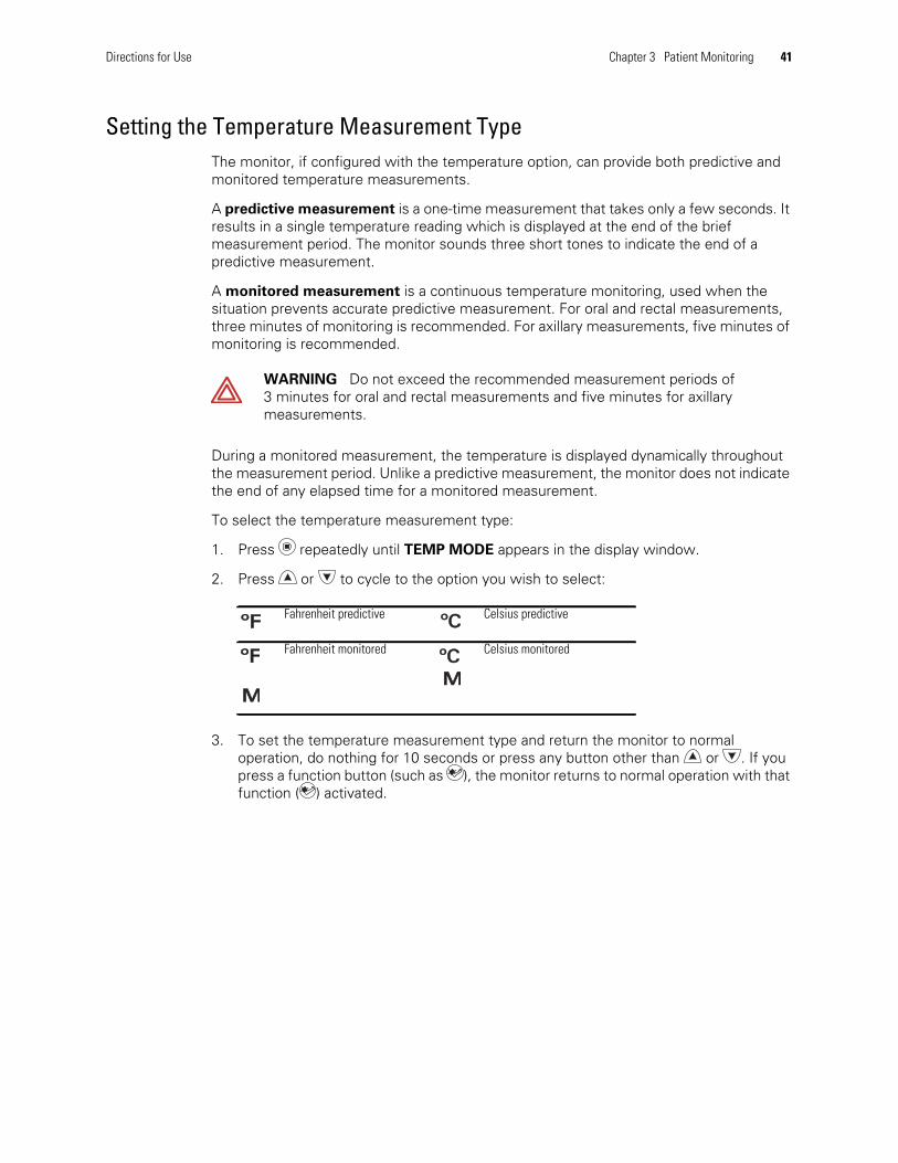
Setting the Temperature Measurement TypeThe monitor, if configured with the temperature option, can provide both predictive andmonitored temperature measurements.
A predictive measurement is a one-time measurement that takes only a few seconds. Itresults in a single temperature reading which is displayed at the end of the briefmeasurement period. The monitor sounds three short tones to indicate the end of apredictive measurement.
A monitored measurement is a continuous temperature monitoring, used when thesituation prevents accurate predictive measurement. For oral and rectal measurements,three minutes of monitoring is recommended. For axillary measurements, five minutes ofmonitoring is recommended.
During a monitored measurement, the temperature is displayed dynamically throughoutthe measurement period. Unlike a predictive measurement, the monitor does not indicatethe end of any elapsed time for a monitored measurement.
To select the temperature measurement type:
1. Press repeatedly until TEMP MODE appears in the display window.
2. Press or to cycle to the option you wish to select:
3. To set the temperature measurement type and return the monitor to normaloperation, do nothing for 10 seconds or press any button other than or . If youpress a function button (such as ), the monitor returns to normal operation with thatfunction ( ) activated.
WARNING Do not exceed the recommended measurement periods of3 minutes for oral and rectal measurements and five minutes for axillarymeasurements.
Fahrenheit predictive Celsius predictive
Fahrenheit monitored Celsius monitored
ºFºF ºCºC
ºFºF
MMMMºCºC
42 Chapter 3 Patient Monitoring Welch Allyn Vital Signs Monitor 300 Series
Loading a Probe Cover1. Holding the probe handle with your thumb and two fingers on the indentations of the
probe handle, withdraw the probe from the probe well.
2. Insert the probe into a probe cover and press the probe handle down firmly. Theprobe handle moves slightly to engage the probe cover.
Ejecting a Used Probe CoverDo not touch the used probe cover.
1. Position the probe over an appropriate disposal receptacle.
2. While holding the probe securely, push the probe cover ejector button (blue or red) toremove the probe cover into the disposal receptacle.
Predictive Temperature Measurement
To set up for predictive temperatures, please refer to the procedure described in“Changing Temperature Type and Measurement Units” on page 25.
To take a predictive temperature, follow these steps:
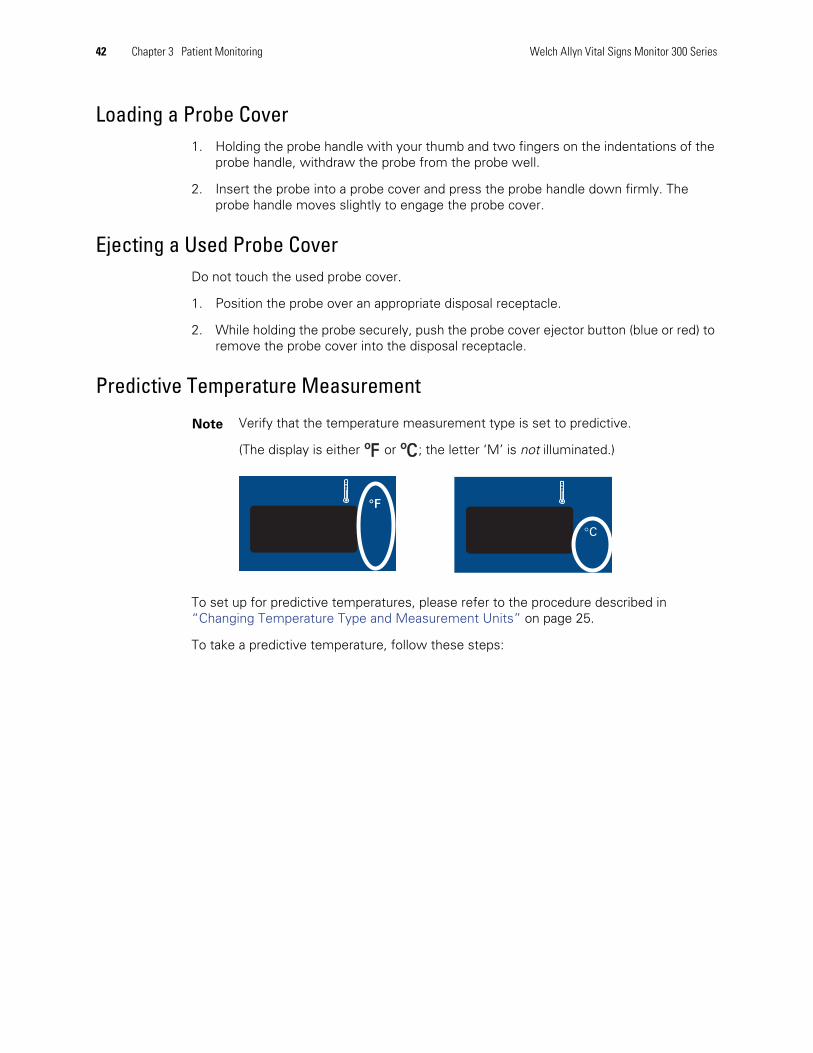
Note Verify that the temperature measurement type is set to predictive.
(The display is either or ; the letter ‘M’ is not illuminated.)ºFºF ºCºC

Directions for Use Chapter 3 Patient Monitoring 43
Oral Predictive
When used correctly, the monitor produces an accurate oral temperature measurement inless than 6 seconds.
1. Remove the temperature probe from the probe well.
The temperature probe runs a self-test, displaying 188.8 for a few seconds. When it isready for use, the temperature window clears, and then OrL appears in thetemperature window.
2. Load a new probe cover by inserting the probe into a probe cover and pressingthe probe handle down firmly. The probe handle moves slightly to engage theprobe cover.
3. Place the probe tip under the patient’s tongue, on either side of the mouth and deepin the rear sublingual pocket.
4. Have the patient close his/her lips around the probe.
Note For oral temperatures, use only the oral probe (blue ejection button) and the blueprobe well.
Caution Use only Welch Allyn probe covers. The use of any other probe cover, orfailing to use a probe cover, can produce measurement errors or inaccuracies.
Caution If the patient bites the probe, the probe can be damaged.
Sublingual pockets
44 Chapter 3 Patient Monitoring Welch Allyn Vital Signs Monitor 300 Series
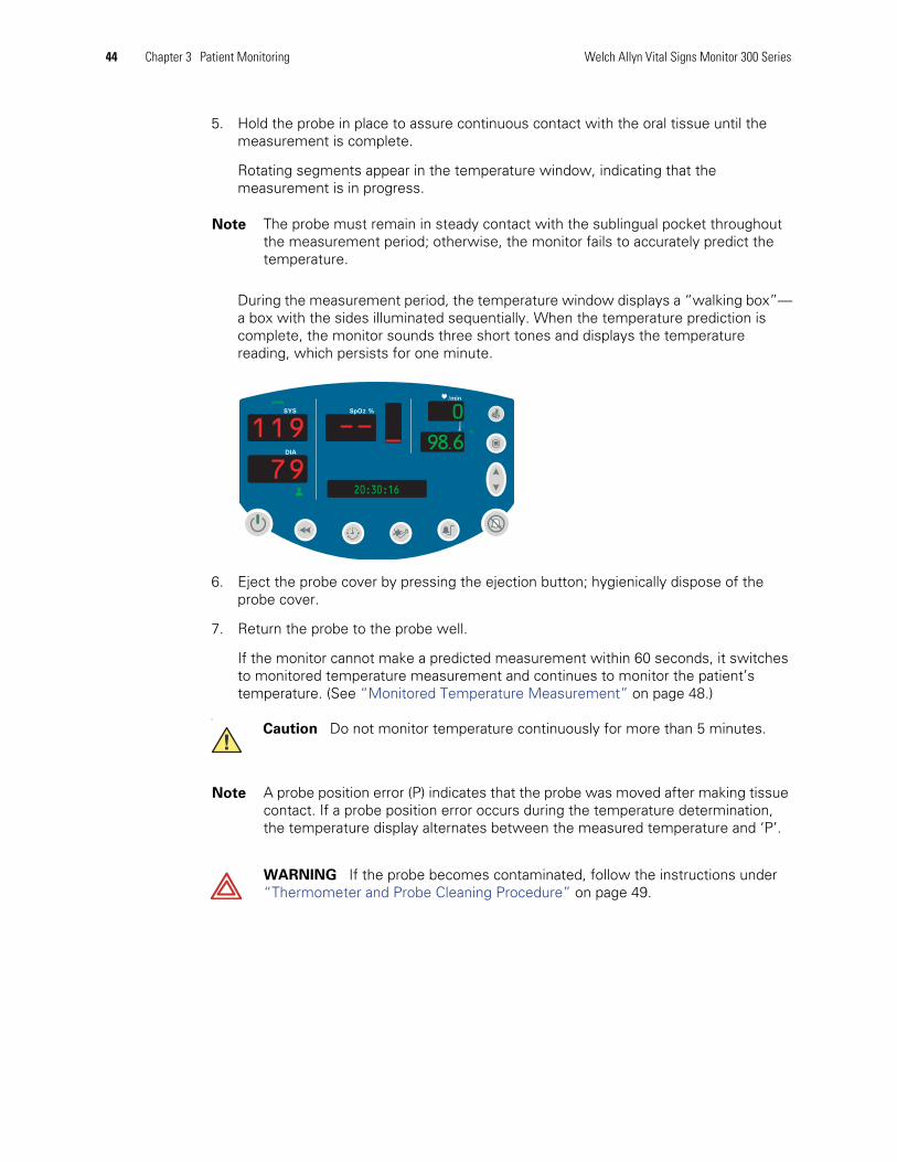
5. Hold the probe in place to assure continuous contact with the oral tissue until themeasurement is complete.
Rotating segments appear in the temperature window, indicating that themeasurement is in progress.
During the measurement period, the temperature window displays a “walking box”—a box with the sides illuminated sequentially. When the temperature prediction iscomplete, the monitor sounds three short tones and displays the temperaturereading, which persists for one minute.
6. Eject the probe cover by pressing the ejection button; hygienically dispose of theprobe cover.
7. Return the probe to the probe well.
If the monitor cannot make a predicted measurement within 60 seconds, it switchesto monitored temperature measurement and continues to monitor the patient’stemperature. (See “Monitored Temperature Measurement” on page 48.)
c
Note The probe must remain in steady contact with the sublingual pocket throughoutthe measurement period; otherwise, the monitor fails to accurately predict thetemperature.
Caution Do not monitor temperature continuously for more than 5 minutes.
Note A probe position error (P) indicates that the probe was moved after making tissuecontact. If a probe position error occurs during the temperature determination,the temperature display alternates between the measured temperature and ‘P’.
WARNING If the probe becomes contaminated, follow the instructions under“Thermometer and Probe Cleaning Procedure” on page 49.
SYS
DIA
SpO2 %
/minmmHg
ºFºF
0
98.6
20:30:1679
119
Directions for Use Chapter 3 Patient Monitoring 45
Axillary Predictive
When used correctly, the monitor produces an accurate axillary temperaturemeasurement in less than 15 seconds for adults and in less than 13 seconds forpediatric patients.
Use Axillary Pediatric (AP) measurements for patients up to 17 years old.
Use Axillary Adult (AA) measurements for patients 18 years old and older.
1. Remove the temperature probe from the probe holder.
The temperature probe runs a self-test, displaying 188.8 for a few seconds. When it isready for use, the temperature window clears, and then OrL appears in thetemperature window.
2. Press or to change the display to AP or AA.
3. Load a new probe cover by inserting the probe into a probe cover and pressingthe probe handle down firmly. The probe handle moves slightly to engage theprobe cover.
4. Lift the patient’s arm to fully expose the axilla.
Note For axillary temperatures, use only the oral probe (blue ejection button) and theblue probe well.
Caution Use only Welch Allyn probe covers. The use of any other probe cover, orfailing to use a probe cover, can produce measurement errors or inaccuracies.
Note Be sure that nothing touches the probe tip before you place it in the axillarymeasurement site.
Note Do not allow the probe tip to make contact with the patient until the probeis placed in the measurement site. Any such contact can cause aninaccurate reading.
46 Chapter 3 Patient Monitoring Welch Allyn Vital Signs Monitor 300 Series
5. Place the probe tip as high as possible in the axilla, and then bring the patient’s armdown to make maximum contact with the probe tip. Hold the patient’s arm in thisposition, keeping the patient as still as possible, for the duration of the measurement.
During the measurement period, the temperature window displays a “walking box”—a box with the sides illuminated sequentially. When the temperature prediction iscomplete, the monitor briefly sounds a tone and displays the temperature reading,which remains on the display for one minute.
6. Remove the probe from the patient’s axilla.
7. Eject the probe cover by pressing the ejection button; hygienically dispose of theprobe cover.
8. Return the probe to the probe well.
If the monitor cannot make a predicted measurement within 60 seconds, it switchesto making a monitored temperature measurement. (See “Monitored TemperatureMeasurement” on page 48.)
Note Be sure that the probe tip is fully covered by the axilla and the arm, and that it isnot touching any clothing. Do not attempt to take an axillary temperature readingthrough the patient’s clothing.
Caution Do not monitor temperature continuously for more than 5 minutes.
Note If a probe position error occurs during the temperature determination, thetemperature display alternates between the measured temperature and ‘P’.
WARNING If the probe becomes contaminated, follow the instructions under“Thermometer and Probe Cleaning Procedure” on page 49.
Directions for Use Chapter 3 Patient Monitoring 47
Rectal Predictive
When used correctly, the monitor produces an accurate rectal temperature measurementin less than 13 seconds.
1. Remove the temperature probe from the probe holder.
The temperature probe runs a self-test, displaying ‘188.8’ for a few seconds. When itis ready for use, a double tone sounds, the temperature window clears, and then rEC
appears in the message window.
2. Load a probe cover onto the probe.
3. Apply a thin coat of water-based lubricant to the tip of the probe cover.
4. Separate the patient’s buttocks with one hand.
5. Insert the probe tip 1.5 centimeter (5/8-inch) inside the rectal sphincter. Tilt the probeslightly to ensure good tissue contact, and keep the buttocks separated throughoutthe duration of the measurement.
During the measurement period, the temperature window displays a “walking box”—a box with the sides illuminated sequentially. When the measurement is complete,the monitor sounds a tone and displays the measurement in the temperaturewindow.
The monitor displays the temperature reading for one minute.
6. Remove the probe.
7. Eject the probe cover by pressing the ejection button, and hygienically dispose of it.
8. Return the probe to the probe well.
Note For rectal temperatures, use only the rectal probe (red ejection button) and thered probe well.
WARNING Use extreme care to avoid any risk of bowel perforation.
Note If a probe position error occurs during the temperature determination, thetemperature display alternates between the measured temperature and ‘P’.
WARNING If the probe becomes contaminated, follow the instructions under“Thermometer and Probe Cleaning Procedure” on page 49.
48 Chapter 3 Patient Monitoring Welch Allyn Vital Signs Monitor 300 Series
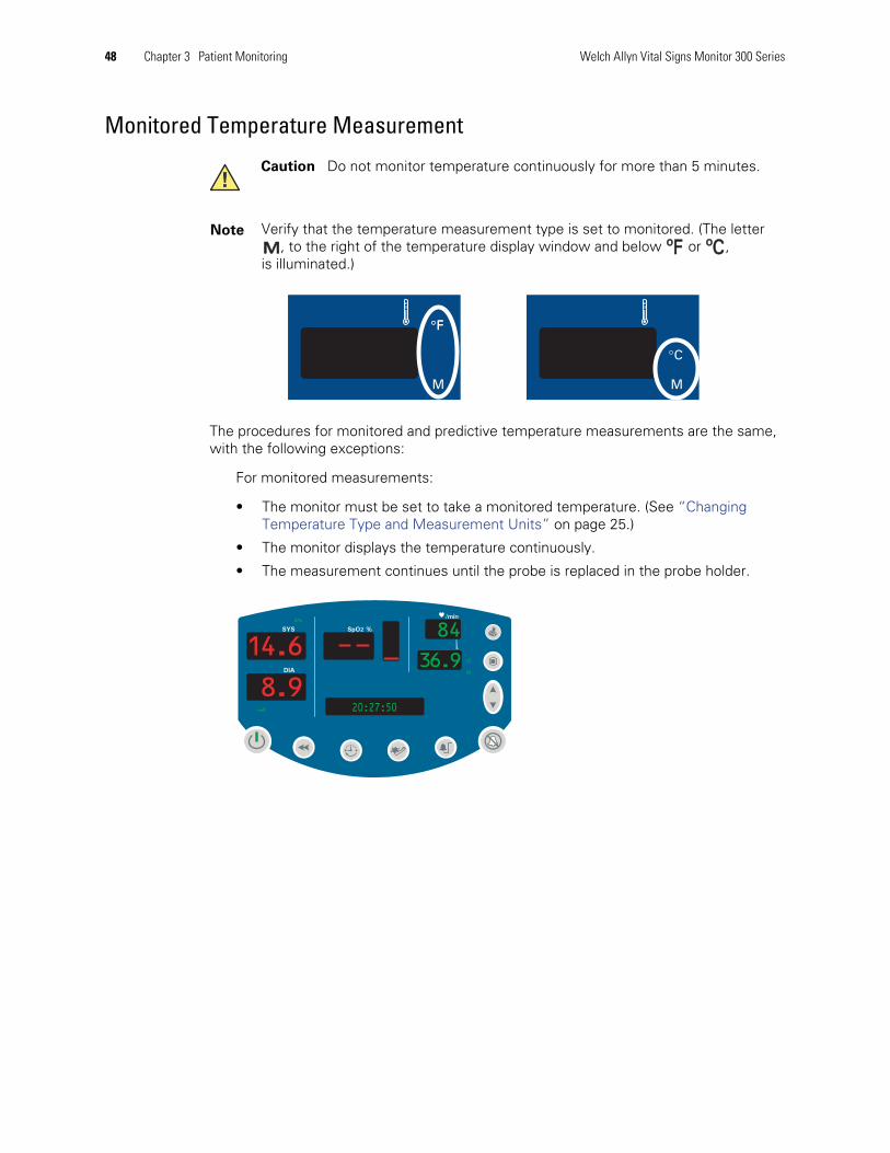
Monitored Temperature Measurement
The procedures for monitored and predictive temperature measurements are the same,with the following exceptions:
For monitored measurements:
• The monitor must be set to take a monitored temperature. (See “ChangingTemperature Type and Measurement Units” on page 25.)
• The monitor displays the temperature continuously.
• The measurement continues until the probe is replaced in the probe holder.
Caution Do not monitor temperature continuously for more than 5 minutes.
Note Verify that the temperature measurement type is set to monitored. (The letter, to the right of the temperature display window and below or ,
is illuminated.)MM ºFºF ºCºC
SYS
DIA
SpO2 %
/min
ºCºC
M
kPa
84
36.9
20:27:508.9
14.6
Directions for Use Chapter 3 Patient Monitoring 49
Thermometer and Probe Cleaning Procedure1. Wipe the thermometer regularly with a cloth dampened with warm water and a mild
detergent solution.
2. Occasionally clean the thermometer and probe as necessary with either a 70%isopropyl alcohol or a 10% solution of chlorine bleach.
Removable Probe Well Cleaning Procedure1. Remove the probe from the probe well, remove the probe well from the monitor, and
unplug the thermometer cable connector from the monitor.
2. Clean the inner and outer surfaces of the probe well by swabbing with a clothdampened with 70% isopropyl alcohol or a 10% solution of chlorine bleach. The probewell can be immersed during cleaning.
3. Thoroughly dry all surfaces.
4. Reassemble the thermometer components.
5. Reconnect the thermometer cable to the monitor, making sure it clicks into place.
6. Reinstall the probe well into the monitor.
7. Insert the probe into the probe well.
Caution Do not immerse or soak the thermometer or probe in any type of fluid.
Caution Do not use steam, heat, or gas sterilization on the thermometeror probe.
Caution Do not autoclave the thermometer or probe.
Caution Do not use hard, sharp, or abrasive objects to clean the probe well.
Caution Do not use steam, heat, or gas sterilization on the probe well.
Caution Do not autoclave the probe well.
Note You can replace any components of the thermometer, including the probe well.
WARNING Use only accessories approved by Welch Allyn. Visitwww.welchallyn.com. The use of any other accessories can result in inaccuratepatient data, can damage the equipment, and can void your product warranty.

50 Chapter 3 Patient Monitoring Welch Allyn Vital Signs Monitor 300 Series
4
51
Alarms and Alerts
Responding to a Patient Alarm
A patient alarm occurs when a vital-sign measurement falls outside of programmed limits.
During a patient alarm, the monitor sounds the alarm tone—a repeating series ofintermittent short tones—and flashes the associated numerics in the appropriate window.The alarm also activates the Nurse Call relay if the Nurse Call cable is connected.
Respond as follows:
1. Press to immediately silence the alarm tone.
• For SpO2-related alarms, the alarm resumes 90 seconds later if the alarmcondition has not been corrected.
• For NIBP-related alarms, the alarm is reset.
• For MAP-related alarms, the MAP measurement readings are displayed inflashing text on the message display.
2. Check the patient and provide appropriate care.
WARNING If you turn off any alarm limits while responding to an alarm, verifyalarm limits before you resume patient monitoring.
WARNING If a patient alarm and an equipment alert occur at the same time,take care of the patient alarm first.

52 Chapter 4 Alarms and Alerts Welch Allyn Vital Signs Monitor 300 Series
Responding to an Equipment Alert
Recoverable Temperature, NIBP, or SpO2 Alert—Not EscalatedMost recoverable equipment alerts are not escalated to the level of patient alarms. Whenan unescalated alert occurs, take the necessary steps to correct the equipment problemand then resume patient monitoring.
For an unescalated equipment alert for Temperature, NIBP, or SpO2, the monitor doesthe following:
• Beeps once
• Displays an error code (Cxx) in the relevant window—Temp, SYS, DIA, or SpO2
Recoverable SpO2 Alert—EscalatedAn SpO2 equipment alert is always escalated immediately to the level of a patient alarm ifit occurs when both of the following conditions exist:
• SpO2 monitoring has begun and the monitor has recorded an SpO2measurement
• An SpO2 or Pulse Rate alarm limit has been set
See “Responding to a Patient Alarm” on page 51.
Recoverable NIBP Alert—EscalatedAn NIBP equipment alert is escalated to the level of a patient alarm whenever both of thefollowing conditions exist:
• Two consecutive NIBP equipment alerts occur while the monitor is takingautomatic NIBP/PR measurements
• Alarms are enabled
See “Responding to a Patient Alarm” on page 51.
WARNING If a patient alarm and an equipment alert occur at the same time,take care of the patient alarm first.
Note For information about a battery alert, see “Battery Low Warning” on page 69and “Battery Failure” on page 69.
Directions for Use Chapter 4 Alarms and Alerts 53
Nonrecoverable AlertsWhen the monitor detects a nonrecoverable equipment problem, it does the following
• Displays an error code in the SYS window, and shuts off the display to allother windows
• Stops patient monitoring
• Stops the pump and opens the air valve
• Activates the Nurse Call relay (if connected)
• Produces an audible tone
• Shuts down as soon as is pressed or one minute has elapsed
Response
For both recoverable and nonrecoverable equipment alerts, respond as follows:
1. Press to immediately silence the alert tone.
2. Determine what caused the alert and correct the problem.
54 Chapter 4 Alarms and Alerts Welch Allyn Vital Signs Monitor 300 Series
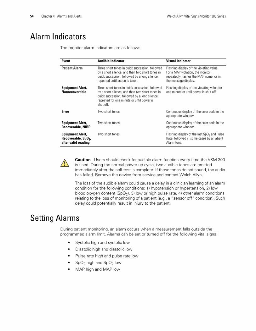
Alarm IndicatorsThe monitor alarm indicators are as follows:
Setting AlarmsDuring patient monitoring, an alarm occurs when a measurement falls outside theprogrammed alarm limit. Alarms can be set or turned off for the following vital signs:
• Systolic high and systolic low
• Diastolic high and diastolic low
• Pulse rate high and pulse rate low
• SpO2 high and SpO2 low
• MAP high and MAP low
Event Audible Indicator Visual Indicator
Patient Alarm Three short tones in quick succession, followedby a short silence, and then two short tones inquick succession, followed by a long silence;repeated until action is taken.
Flashing display of the violating value.For a MAP violation, the monitorrepeatedly flashes the MAP numerics inthe message display.
Equipment Alert,Nonrecoverable
Three short tones in quick succession, followedby a short silence, and then two short tones inquick succession, followed by a long silence;repeated for one minute or until power isshut off.
Flashing display of the violating value forone minute or until power is shut off.
Error Two short tones Continuous display of the error code in theappropriate window.
Equipment Alert,Recoverable, NIBP
Two short tones Continuous display of the error code in theappropriate window.
Equipment Alert,Recoverable, SpO2,after valid reading
Two short tones Flashing display of the last SpO2 and PulseRate, followed in some cases by a PatientAlarm tone.
Caution Users should check for audible alarm function every time the VSM 300is used. During the normal power-up cycle, two audible tones are emittedimmediately after the self-test is complete. If these tones do not sound, the audiohas failed. Remove the device from service and contact Welch Allyn.
The loss of the audible alarm could cause a delay in a clinician learning of an alarmcondition for the following conditions: 1) hypotension or hypertension, 2) lowblood oxygen content (SpO2), 3) low or high pulse rate, 4) other alarm conditionsrelating to the loss of monitoring of a patient (e.g., a “sensor off” condition). Suchdelay could potentially result in injury to the patient.
Directions for Use Chapter 4 Alarms and Alerts 55
Set alarms for systolic and diastolic blood pressure, pulse rate, and SpO2 as follows:
1. Press .
• All display windows are blanked, other than the message window and theSYS window.
• The message window displays HIGH ALARM.
• The SYS window displays the current alarm setting for the upper limit of systolicblood pressure. This setting is a numeric blood pressure level or it is ‘- -’,indicating that no alarm is set for the selected vital sign.
2. For the selected vital sign, do one of the following:
• Leave the limit unchanged or
• Press or as needed to change the limit to another value or to ‘- -’ to disablethe alarm.
3. Press to accept the displayed alarm limit and advance to the next vital sign.
The display moves to the next window (for example, from SYS HIGH to SYS LOW, orfrom SYS LOW to DIA HIGH).
4. To continue changing alarm limits, repeat from step 2; to return to normal operation,do nothing for 10 seconds.
To set the MAP alarm limits, if MAP is enabled:
5. Continue from (step 3) until you have cycled through all of the display windows; thatis, until you have cycled through SpO2 LOW.
The display moves to the message window, which displays the current MAP highalarm limit, as follows:
MAP XXX mmHg or MAP XXX kPa
MAP XXX mmHg or MAP XXX kPa
Note For patient safety, all alarms are reset to the factory default levels whenever thepatient type is changed. This means that you must either accept the defaultalarm limits or set new limits every time you change patient type ( , , or ).
The ‘high’ alarm for any vital sign is always higher than the ‘low’ alarm for thesame vital sign. For example, the alarm limit for systolic high is always higherthan the alarm limit for systolic low.
A reading that exactly reaches the alarm threshold without crossing the alarmthreshold does not qualify as an alarm condition.
56 Chapter 4 Alarms and Alerts Welch Allyn Vital Signs Monitor 300 Series
6. Change or accept the MAP high alarm limit as described above (from step 2).
7. Press to step to the MAP low alarm limit.
8. Change or accept the MAP low alarm limit.
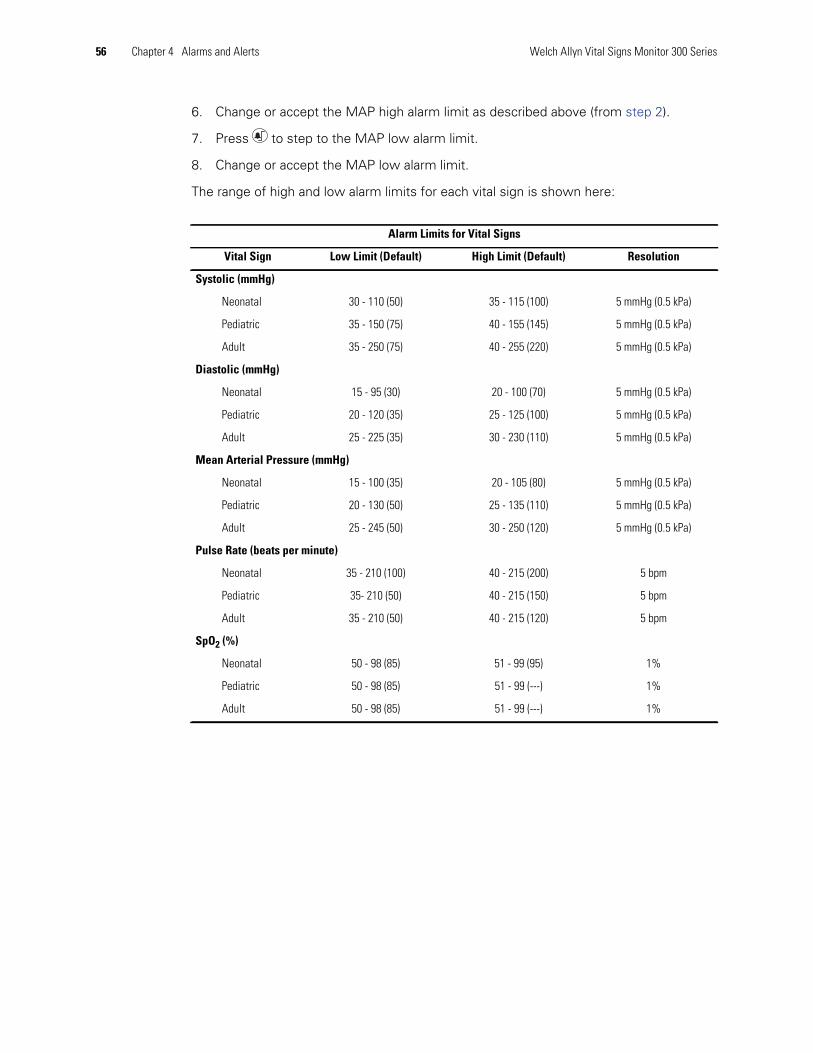
The range of high and low alarm limits for each vital sign is shown here:
Alarm Limits for Vital Signs
Vital Sign Low Limit (Default) High Limit (Default) Resolution
Systolic (mmHg)
Neonatal 30 - 110 (50) 35 - 115 (100) 5 mmHg (0.5 kPa)
Pediatric 35 - 150 (75) 40 - 155 (145) 5 mmHg (0.5 kPa)
Adult 35 - 250 (75) 40 - 255 (220) 5 mmHg (0.5 kPa)
Diastolic (mmHg)
Neonatal 15 - 95 (30) 20 - 100 (70) 5 mmHg (0.5 kPa)
Pediatric 20 - 120 (35) 25 - 125 (100) 5 mmHg (0.5 kPa)
Adult 25 - 225 (35) 30 - 230 (110) 5 mmHg (0.5 kPa)
Mean Arterial Pressure (mmHg)
Neonatal 15 - 100 (35) 20 - 105 (80) 5 mmHg (0.5 kPa)
Pediatric 20 - 130 (50) 25 - 135 (110) 5 mmHg (0.5 kPa)
Adult 25 - 245 (50) 30 - 250 (120) 5 mmHg (0.5 kPa)
Pulse Rate (beats per minute)
Neonatal 35 - 210 (100) 40 - 215 (200) 5 bpm
Pediatric 35- 210 (50) 40 - 215 (150) 5 bpm
Adult 35 - 210 (50) 40 - 215 (120) 5 bpm
SpO2 (%)
Neonatal 50 - 98 (85) 51 - 99 (95) 1%
Pediatric 50 - 98 (85) 51 - 99 (---) 1%
Adult 50 - 98 (85) 51 - 99 (---) 1%
Directions for Use Chapter 4 Alarms and Alerts 57
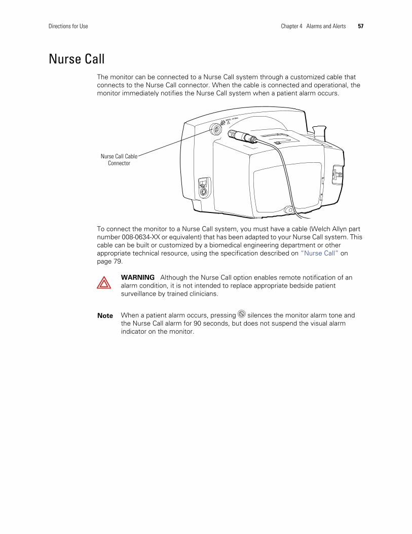
Nurse CallThe monitor can be connected to a Nurse Call system through a customized cable thatconnects to the Nurse Call connector. When the cable is connected and operational, themonitor immediately notifies the Nurse Call system when a patient alarm occurs.
To connect the monitor to a Nurse Call system, you must have a cable (Welch Allyn partnumber 008-0634-XX or equivalent) that has been adapted to your Nurse Call system. Thiscable can be built or customized by a biomedical engineering department or otherappropriate technical resource, using the specification described on “Nurse Call” onpage 79.
WARNING Although the Nurse Call option enables remote notification of analarm condition, it is not intended to replace appropriate bedside patientsurveillance by trained clinicians.
Note When a patient alarm occurs, pressing silences the monitor alarm tone andthe Nurse Call alarm for 90 seconds, but does not suspend the visual alarmindicator on the monitor.
Nurse Call CableConnector
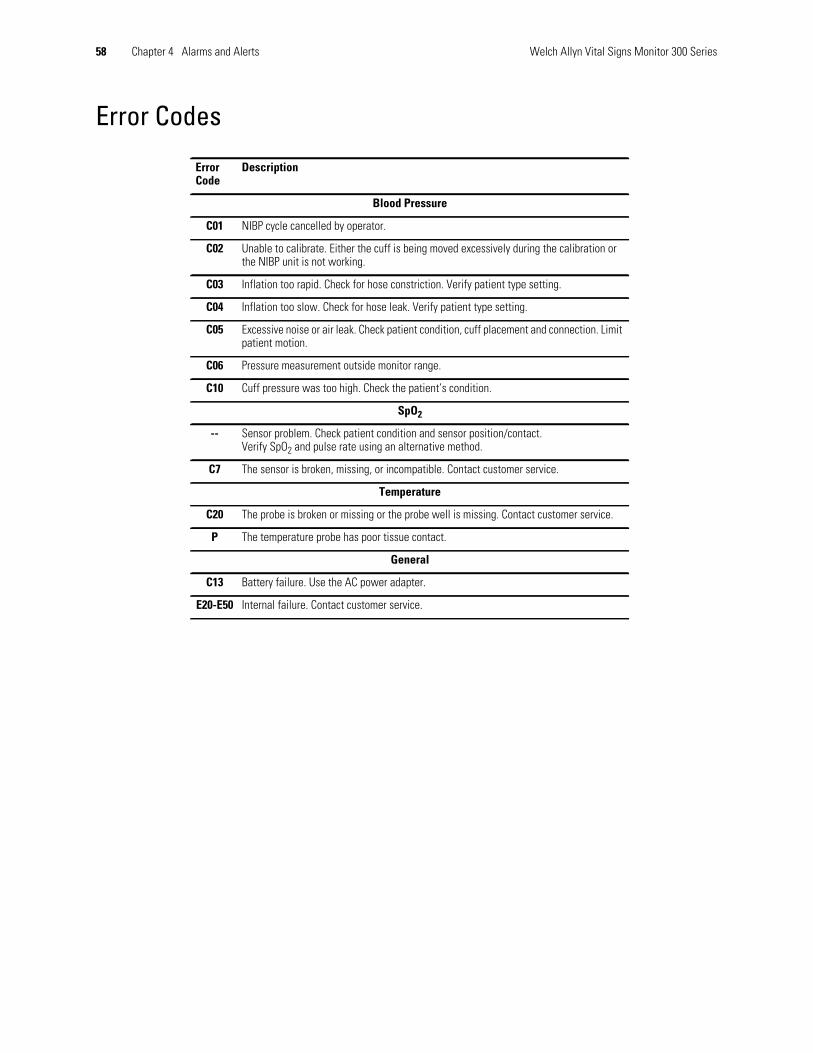
58 Chapter 4 Alarms and Alerts Welch Allyn Vital Signs Monitor 300 Series
Error Codes
ErrorCode
Description
Blood Pressure
C01 NIBP cycle cancelled by operator.
C02 Unable to calibrate. Either the cuff is being moved excessively during the calibration orthe NIBP unit is not working.
C03 Inflation too rapid. Check for hose constriction. Verify patient type setting.
C04 Inflation too slow. Check for hose leak. Verify patient type setting.
C05 Excessive noise or air leak. Check patient condition, cuff placement and connection. Limitpatient motion.
C06 Pressure measurement outside monitor range.
C10 Cuff pressure was too high. Check the patient’s condition.
SpO2
-- Sensor problem. Check patient condition and sensor position/contact.Verify SpO2 and pulse rate using an alternative method.
C7 The sensor is broken, missing, or incompatible. Contact customer service.
Temperature
C20 The probe is broken or missing or the probe well is missing. Contact customer service.
P The temperature probe has poor tissue contact.
General
C13 Battery failure. Use the AC power adapter.
E20-E50 Internal failure. Contact customer service.
5
59
Reviewing Patient DataYou can review stored patient data either by viewing it on the monitor or by printing it.
Displaying Stored Patient Data1. Press to display the most recent stored set of patient vital-signs data.
• The monitor interrupts the dynamic display of any current vital-signmeasurement.
• The message READING appears in the message window, with a data-setsequence number and the time of the displayed reading. (During a patient datareview, if MAP is enabled, this display alternates every two seconds with theMAP display.)
2. Press or to cycle through the stored measurement data sets. (The monitorstores 99 measurement cycles.)
3. To return to normal operation, press any button other than or . If you press afunction button (such as ), the monitor returns to normal operation with thatfunction ( ) activated.
Printing Patient Data
The printer provides a way to view and save patient vital-signs data. It can be configuredto print all stored data as a single batch or to print a continuing stream of data as the datais recorded in memory. (See “Selecting Stream or Batch Printing” on page 27.)
Note The information in this section pertains only to monitors configured with theoptional thermal printer.

60 Chapter 5 Reviewing Patient Data Welch Allyn Vital Signs Monitor 300 Series
To Start and Stop Printing• If the monitor is not printing, press to start printing.
• If the monitor is printing, press to stop printing. (If the monitor is set to Streamprinting, the printer prints a footer before stopping.)
Batch PrintingAfter a patient has been continuously monitored over some period, a clinician can use themonitor’s batch printing capability to print all of the measurements that were stored inthe monitor’s memory over the monitoring period.
When the monitor is configured for batch printing, and while it is in normal operatingmode, press to print all readings stored in memory (up to 99 cycles), starting with theoldest measurement cycle and working forward. The message PRINTING is displayedduring the batch print, and all monitor controls other than and are disabled. Batchprinting continues until one of the following occurs:
• All stored data has been printed.
• is pressed again.
• A battery failure condition.
• A nonrecoverable error condition is detected.
In any of these cases, printing stops immediately.
Stream PrintingAlternatively, a clinician can choose to print a continuous stream of vital signs, where themeasurement information is printed as soon as the results of each cycle are recorded.
When the monitor is configured for stream printing, and while it is in normal operatingmode, press to immediately begin stream printing. Stream printing continues until oneof the following occurs:
Note The print button is not enabled during an NIBP cycle or during a nonrecoverableequipment alert.
Note If the monitor is configured for Stream printing but printing is disabled, you canpress and hold for 3 seconds to immediately start a Batch print job. When thisBatch job ends, the monitor is still configured for Stream printing.

Directions for Use Chapter 5 Reviewing Patient Data 61
• is pressed again; the monitor prints an error log (if any errors occurred) and afooter, and then printing stops.
• A nonrecoverable error condition is detected; printing stops immediately.
• A battery failure condition is detected. Printing is suspended as long as thebattery failure continues; if the AC power adapter is connected before the monitorshuts down, printing resumes.
Printer OutputThe printer standard report consists of a header, patient information, patient data (tableheading, date, time, range and alarm flags, and measurement readings), an error legendand a footer. If the monitor receives a print request and no data is available, it prints onlythe header and footer.
Header
Patient Information
Patient Data
The contents of the Patient Data block reflect the configuration of the monitor; that is,with or without the SpO2 option and with or without the temperature option.
For a single cycle, all data except temperature is printed on one line; the temperaturedata, if it exists, is printed on a second line. If the data for a single parameter is notavailable, nothing is printed in the space provided for that parameter.
The patient data is displayed in a table consisting of a table heading, the current date, androws of patient vital-sign data.
| (R) || Vital Signs Monitor || |
Welch Allyn
| Patient Name:___________________ || Patient ID:_____________________ || Physician:______________________ || Procedure:______________________ || Comments:_______________________ || ________________________________ || ________________________________ || |
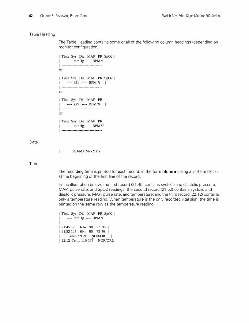
62 Chapter 5 Reviewing Patient Data Welch Allyn Vital Signs Monitor 300 Series
Table Heading
The Table Heading contains some or all of the following column headings (depending onmonitor configuration):
Date
Time
The recording time is printed for each record, in the form hh:mm (using a 24-hour clock),at the beginning of the first line of the record.
In the illustration below, the first record (21:45) contains systolic and diastolic pressure,MAP, pulse rate, and SpO2 readings; the second record (21:52) contains systolic anddiastolic pressure, MAP, pulse rate, and temperature; and the third record (22:12) containsonly a temperature reading. When temperature is the only recorded vital sign, the time isprinted on the same row as the temperature reading.
| Time Sys Dia MAP PR SpO2 || ---- mmHg ---- BPM % || --------------------------------- |or
| Time Sys Dia MAP PR SpO2 || ---- kPa ---- BPM % || --------------------------------- |or
| Time Sys Dia MAP PR || ---- kPa ---- BPM % || --------------------------------- |or
| Time Sys Dia MAP PR || ---- mmHg ---- BPM % || --------------------------------- |
| DD-MMM-YYYY |
| Time Sys Dia MAP PR SpO2 || ---- mmHg ---- BPM % || --------------------------------- || 21:45 125 69 90 72 98 || 21:52 125 69 90 72 98 || Temp 99.2F NOR/ORL || 22:12 Temp 110.0F NOR/ORL |
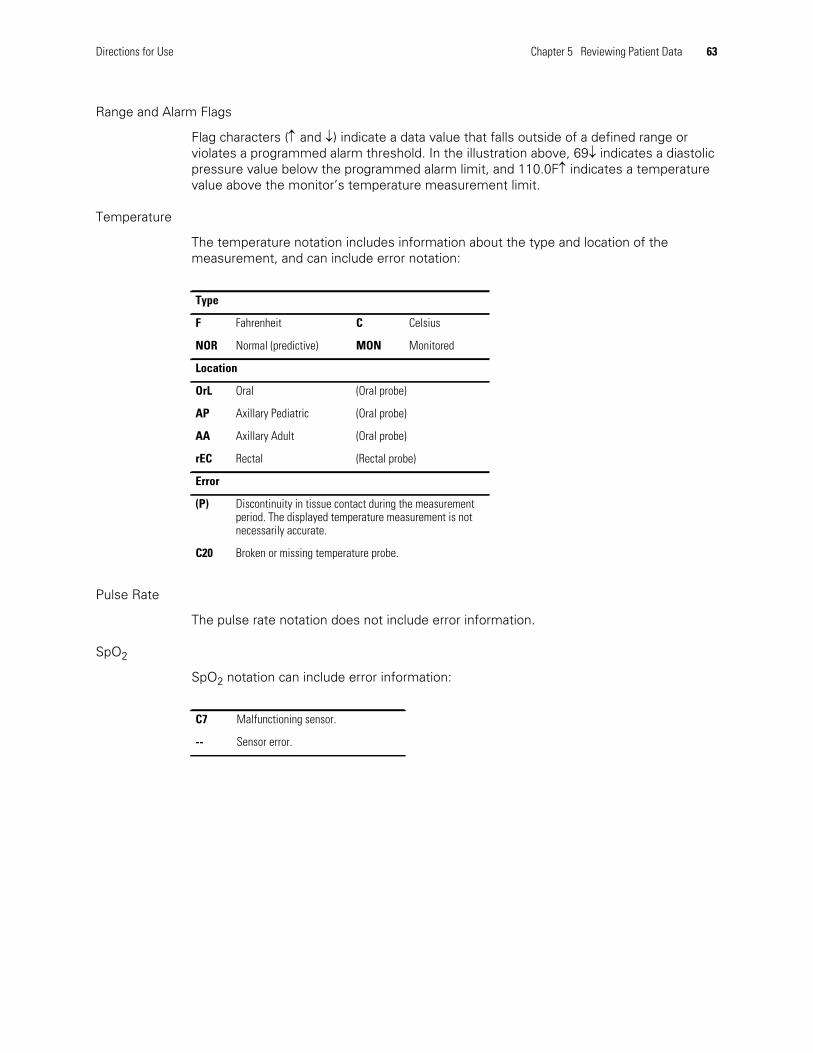
Directions for Use Chapter 5 Reviewing Patient Data 63
Range and Alarm Flags
Flag characters ( and ) indicate a data value that falls outside of a defined range orviolates a programmed alarm threshold. In the illustration above, 69 indicates a diastolicpressure value below the programmed alarm limit, and 110.0Findicates a temperaturevalue above the monitor’s temperature measurement limit.
Temperature
The temperature notation includes information about the type and location of themeasurement, and can include error notation:
Pulse Rate
The pulse rate notation does not include error information.
SpO2
SpO2 notation can include error information:
Type
F Fahrenheit C Celsius
NOR Normal (predictive) MON Monitored
Location
OrL Oral (Oral probe)
AP Axillary Pediatric (Oral probe)
AA Axillary Adult (Oral probe)
rEC Rectal (Rectal probe)
Error
(P) Discontinuity in tissue contact during the measurementperiod. The displayed temperature measurement is notnecessarily accurate.
C20 Broken or missing temperature probe.
C7 Malfunctioning sensor.
-- Sensor error.
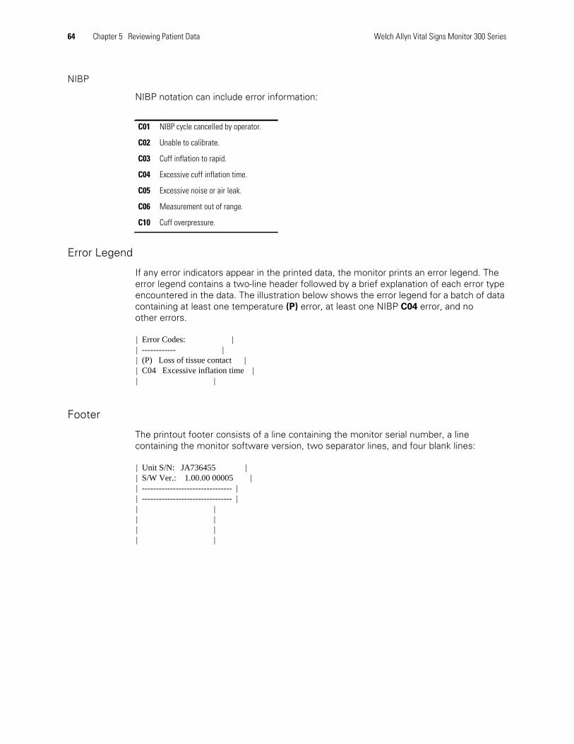
64 Chapter 5 Reviewing Patient Data Welch Allyn Vital Signs Monitor 300 Series
NIBP
NIBP notation can include error information:
Error Legend
If any error indicators appear in the printed data, the monitor prints an error legend. Theerror legend contains a two-line header followed by a brief explanation of each error typeencountered in the data. The illustration below shows the error legend for a batch of datacontaining at least one temperature (P) error, at least one NIBP C04 error, and noother errors.
Footer
The printout footer consists of a line containing the monitor serial number, a linecontaining the monitor software version, two separator lines, and four blank lines:
C01 NIBP cycle cancelled by operator.
C02 Unable to calibrate.
C03 Cuff inflation to rapid.
C04 Excessive cuff inflation time.
C05 Excessive noise or air leak.
C06 Measurement out of range.
C10 Cuff overpressure.
| Error Codes: || ------------ || (P) Loss of tissue contact || C04 Excessive inflation time || |
| Unit S/N: JA736455 || S/W Ver.: 1.00.00 00005 || -------------------------------- || -------------------------------- || || || || |

Directions for Use Chapter 5 Reviewing Patient Data 65
Erasing Patient DataAll patient vital-sign data is erased when the monitor is powered off or when youchange the time and date settings. You can also erase data at any time during normalmonitor operation.
Erasing Data Before Changing the Date and TimeIf you attempt to change the date and time, the monitor prompts you to confirm that youalso want to erase all stored patient data.
To erase patient data, press ; the monitor erases the data and enables the date/timeadjustment. (For information on changing the time and date settings, see “Changing theTime and Date” on page 20.)
Erasing Data During Normal OperationTo erase patient data during normal operation, press and hold for three seconds. Whenthe monitor prompts for confirmation, press to confirm or to cancel. When theerasure is complete, the monitor returns automatically to normal operation. If youcancel the erasure, you can then press any button other than or to return tonormal operation.
Note You cannot change the date and time without also erasing all stored patient data.

66 Chapter 5 Reviewing Patient Data Welch Allyn Vital Signs Monitor 300 Series
Replacing the Printer Paper Supply
To replace the printer paper supply, follow these steps.
1. Press to open the printer door.
2. Insert a new roll of paper.
3. Thread the end of the roll over the roller and through the slot in the printer door,as shown.
4. With one hand, pull lightly on the paper to take up any slack. With the other hand,close the printer door by pushing it down and into place until it clicks.
Note Use only the thermal paper (part number 7052-25) supplied by Welch Allyn. Theuse of any other paper can result in poor printer performance.
Note The paper roll must be installed as shown in the illustration below. If the paper rollis not installed correctly, the printer will not print.
Note Be certain that the paper does not catch in the printer door.
6
67
Operator MaintenanceThis chapter describes the operator maintenance procedures.
CleaningWipe the monitor with a cloth slightly dampened with warm water and a mild detergentor appropriately diluted, nonstaining disinfectant solution.
Wipe the temperature probe with a cloth dampened with alcohol, warm water, or anappropriately diluted, nonstaining disinfectant solution.
NIBP hose and any reusable cuffs: See the manufacturer’s instructions.
SpO2 sensor: See the manufacturer’s instructions.
StorageFor maximum monitor life and optimum performance, store the monitor at roomtemperature in a dry environment.
For prolonged storage, keep the monitor in the original container or in some other dust-proof container.
Before storing the monitor, verify that the printer contains paper.
Caution Never wet the monitor or immerse it in fluid of any kind. Never allowwater to enter any connector ports.
Caution Never immerse any monitor components, such as the NIBP hose orcuff, the temperature probe, or the SpO2 sensor.

68 Chapter 6 Operator Maintenance Welch Allyn Vital Signs Monitor 300 Series
Recycling Monitor Components
Within the EUDo not dispose of this product as ‘unsorted municipal waste’. Prepare it for reuseor separate collection as specified by Directive 2002/96/EC of the EuropeanParliament and the Council of the European Union on Waste Electronic andElectrical Equipment (WEEE).
For more specific disposal information, see www.welchallyn.com/weee, or contact WelchAllyn Customer Service.
Outside the EUWhen the monitor or the battery reaches end of life, recycle it locally according tonational, state, and local regulations, or return it to Welch Allyn.
Note If the monitor or the battery is contaminated, this directive does not apply.
7
69
Reference
Battery Operation
Battery Low WarningWhen the battery charge is low, a warning tone sounds and the Low Battery indicatorflashes continuously. From the time comes on, the battery has enough chargeremaining to perform at least one of the following over the next hour:
• 20 NIBP cycles
• 30 minutes of SpO2 monitoring
• 20 predictive temperature determinations
• a single printing of 99 stored data sets
To avoid a shutdown of the monitor due to battery failure, plug in and connect the ACpower adapter.
Battery FailureIf the monitor continues to run on battery power after comes on, the batteryeventually fails. Battery failure is indicated by the following:
• flashes continuously.
• A short tone repeats continuously. Pressing does not suppress this tone.
• The message LOW BATTERY is displayed in the message window.
• An error code is displayed in the systolic window (SYS) for 10 seconds, and thenall monitor displays are blanked.
• An error signal—2 short tones—sounds once.
70 Chapter 7 Reference Welch Allyn Vital Signs Monitor 300 Series
Battery failure causes the immediate suspension of all monitoring and print functions. Ifthe wall charger is not plugged in, then the monitor shuts off 15 minutes after the batterydischarge reaches failure level. If automatic NIBP is selected, and if the wall charger isplugged in before the monitor shuts down, then automatic measurement cycles resumeas soon as the battery voltage rises above the failure threshold.
Battery ReplacementWhen the battery has reached end of life, replace it with an identical battery from WelchAllyn (reorder number 501-0015-XX).
Caution Always recycle batteries according to local regulations. Never disposeof batteries in waste receptacles.
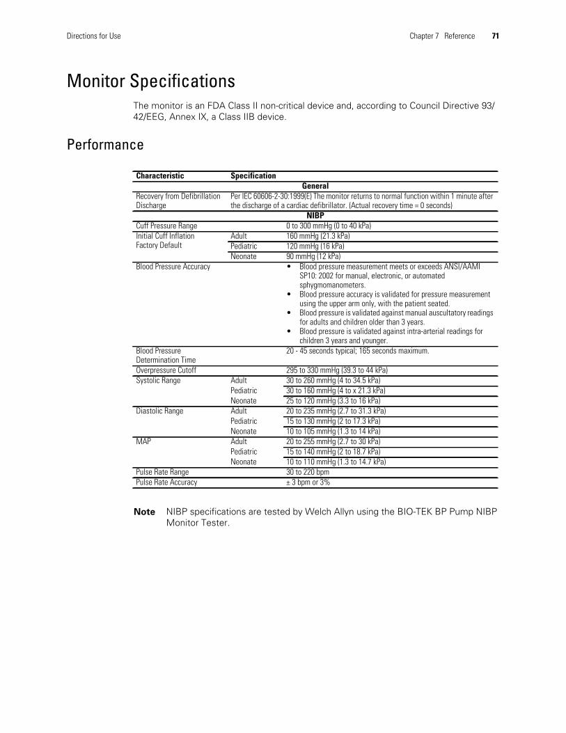
Directions for Use Chapter 7 Reference 71
Monitor SpecificationsThe monitor is an FDA Class II non-critical device and, according to Council Directive 93/42/EEG, Annex IX, a Class IIB device.
Performance
Characteristic SpecificationGeneral
Recovery from DefibrillationDischarge
Per IEC 60606-2-30:1999(E) The monitor returns to normal function within 1 minute afterthe discharge of a cardiac defibrillator. (Actual recovery time = 0 seconds)
NIBPCuff Pressure Range 0 to 300 mmHg (0 to 40 kPa)Initial Cuff InflationFactory Default
Adult 160 mmHg (21.3 kPa)Pediatric 120 mmHg (16 kPa)Neonate 90 mmHg (12 kPa)
Blood Pressure Accuracy • Blood pressure measurement meets or exceeds ANSI/AAMISP10: 2002 for manual, electronic, or automatedsphygmomanometers.
• Blood pressure accuracy is validated for pressure measurementusing the upper arm only, with the patient seated.
• Blood pressure is validated against manual auscultatory readingsfor adults and children older than 3 years.
• Blood pressure is validated against intra-arterial readings forchildren 3 years and younger.
Blood PressureDetermination Time
20 - 45 seconds typical; 165 seconds maximum.
Overpressure Cutoff 295 to 330 mmHg (39.3 to 44 kPa)Systolic Range Adult 30 to 260 mmHg (4 to 34.5 kPa)
Pediatric 30 to 160 mmHg (4 to x 21.3 kPa)Neonate 25 to 120 mmHg (3.3 to 16 kPa)
Diastolic Range Adult 20 to 235 mmHg (2.7 to 31.3 kPa)Pediatric 15 to 130 mmHg (2 to 17.3 kPa)Neonate 10 to 105 mmHg (1.3 to 14 kPa)
MAP Adult 20 to 255 mmHg (2.7 to 30 kPa)Pediatric 15 to 140 mmHg (2 to 18.7 kPa)Neonate 10 to 110 mmHg (1.3 to 14.7 kPa)
Pulse Rate Range 30 to 220 bpmPulse Rate Accuracy ± 3 bpm or 3%
Note NIBP specifications are tested by Welch Allyn using the BIO-TEK BP Pump NIBPMonitor Tester.
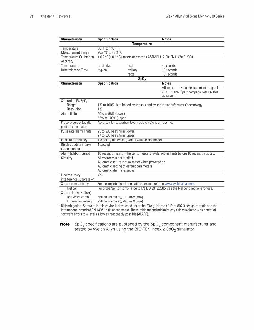
72 Chapter 7 Reference Welch Allyn Vital Signs Monitor 300 Series
Characteristic Specification NotesTemperature
TemperatureMeasurement Range
80 F to 110 F26.7 C to 43.3 C
Temperature CalibrationAccuracy
± 0.2 F (± 0.1 C); meets or exceeds ASTME1112-00; EN12470-3:2000
TemperatureDetermination Time
predictive(typical)
oralaxillaryrectal
4 seconds10 seconds15 seconds
SpO2Characteristic Specification Notes
All sensors have a measurement range of70% - 100%. SpO2 complies with EN ISO9919:2005.
Saturation (% SpO2)RangeResolution
1% to 100%, but limited by sensors and by sensor manufacturers’ technology1%
Alarm limits 50% to 98% (lower)52% to 100% (upper)
Probe accuracy (adult,pediatric, neonate)
Accuracy for saturation levels below 70% is unspecified.
Pulse rate alarm limits 25 to 298 beats/min (lower)27 to 300 beats/min (upper)
Pulse rate accuracy ± 3 beats/min typical; varies with sensor modelDisplay update intervalat the monitor
1 second
Alarm hold-off period 10 seconds; resets if the sensor reports levels within limits before 10 seconds elapses.Circuitry Microprocessor controlled
Automatic self-test of oximeter when powered onAutomatic setting of default parametersAutomatic alarm messages
Electrosurgeryinterference suppression
Yes
Sensor compatibility For a complete list of compatible sensors refer to www.welchallyn.com.Nellcor For probe/sensor compliance to EN ISO 9919:2005, see the Nellcor directions for use.
Sensor lights (Nellcor)Red wavelengthInfrared wavelength
660 nm (nominal), 31.3 mW (max)920 nm (nominal), 28.8 mW (max)
Risk mitigation: Software in this device is developed under the FDA guidance of Part 802.3 design controls and theinternational standard EN 14971 risk management. These mitigate and minimize any risk associated with potentialsoftware errors to a level as low as reasonably possible (ALARP).
Note SpO2 specifications are published by the SpO2 component manufacturer andtested by Welch Allyn using the BIO-TEK Index 2 SpO2 simulator.

Directions for Use Chapter 7 Reference 73
Physical
Characteristic Specification
Dimensions
height 6.6 inches 16.8 cm
width 10.0 inches 25.4 cm
depth 6.0 inches 15.2 cm
Weight Approximately 5.4 lbs (2.4 kg)
Color, Temperature Probe
Oral/Axillary Blue
Rectal Red
Characteristic Specification
Support Self-supporting on rubber feet
Mountable (with available accessories) to the following:
IV pole
Mobile stand
Wall
Portability Recessed carry handle
Mounted on a pole or mobile stand, can be rolled from patient to patient
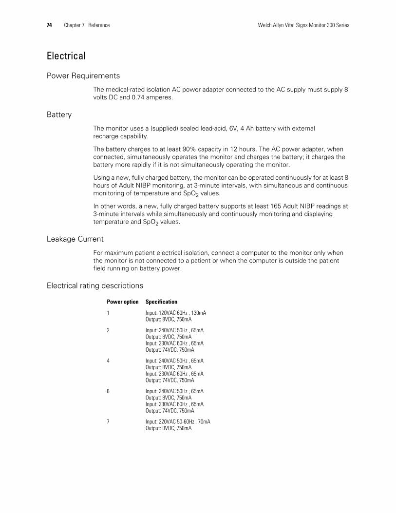
74 Chapter 7 Reference Welch Allyn Vital Signs Monitor 300 Series
Electrical
Power Requirements
The medical-rated isolation AC power adapter connected to the AC supply must supply 8volts DC and 0.74 amperes.
Battery
The monitor uses a (supplied) sealed lead-acid, 6V, 4 Ah battery with externalrecharge capability.
The battery charges to at least 90% capacity in 12 hours. The AC power adapter, whenconnected, simultaneously operates the monitor and charges the battery; it charges thebattery more rapidly if it is not simultaneously operating the monitor.
Using a new, fully charged battery, the monitor can be operated continuously for at least 8hours of Adult NIBP monitoring, at 3-minute intervals, with simultaneous and continuousmonitoring of temperature and SpO2 values.
In other words, a new, fully charged battery supports at least 165 Adult NIBP readings at3-minute intervals while simultaneously and continuously monitoring and displayingtemperature and SpO2 values.
Leakage Current
For maximum patient electrical isolation, connect a computer to the monitor only whenthe monitor is not connected to a patient or when the computer is outside the patientfield running on battery power.
Electrical rating descriptions
Power option Specification
1 Input: 120VAC 60Hz , 130mAOutput: 8VDC, 750mA
2 Input: 240VAC 50Hz , 65mAOutput: 8VDC, 750mAInput: 230VAC 60Hz , 65mAOutput: 74VDC, 750mA
4 Input: 240VAC 50Hz , 65mAOutput: 8VDC, 750mAInput: 230VAC 60Hz , 65mAOutput: 74VDC, 750mA
6 Input: 240VAC 50Hz , 65mAOutput: 8VDC, 750mAInput: 230VAC 60Hz , 65mAOutput: 74VDC, 750mA
7 Input: 220VAC 50-60Hz , 70mAOutput: 8VDC, 750mA

Directions for Use Chapter 7 Reference 75
Environmental
EMC Compliance
The monitor complies with all applicable and required standards for electromagneticinterference.
• It does not normally affect nearby equipment and devices.
• It is not normally affected by nearby equipment and devices.
• It is safe to operate the monitor in the presence of high-frequencysurgical equipment.
• However, it is good practice to avoid using the monitor in extremely closeproximity to other equipment.
Guidance and manufacturer’s declaration—electromagnetic emissions
The Vital Signs Monitor 300 Series monitor is intended for use in the electromagnetic environment specified below. Thecustomer or the user of the monitor should assure that it is used in such an environment.
Emissions test Compliance Electromagnetic environment—guidance
RF emissionsCISPR 11
Group 1 The Vital Signs Monitor 300 Series monitor uses RF energy only for itsinternal function.Therefore, its RF emissions are very low and are notlikely to cause any interference in nearby electronic equipment.
RF emissionsCISPR 11
Class B The Vital Signs Monitor 300 Series monitor is suitable for use in allestablishments, including domestic establishments and those directlyconnected to the public low-voltage power supply network thatsupplies buildings used for domestic purposes.Harmonic emissions
IEC 61000-3-2Class A
Voltagefluctuations/flickeremissions IEC 61000-3-3
Complies
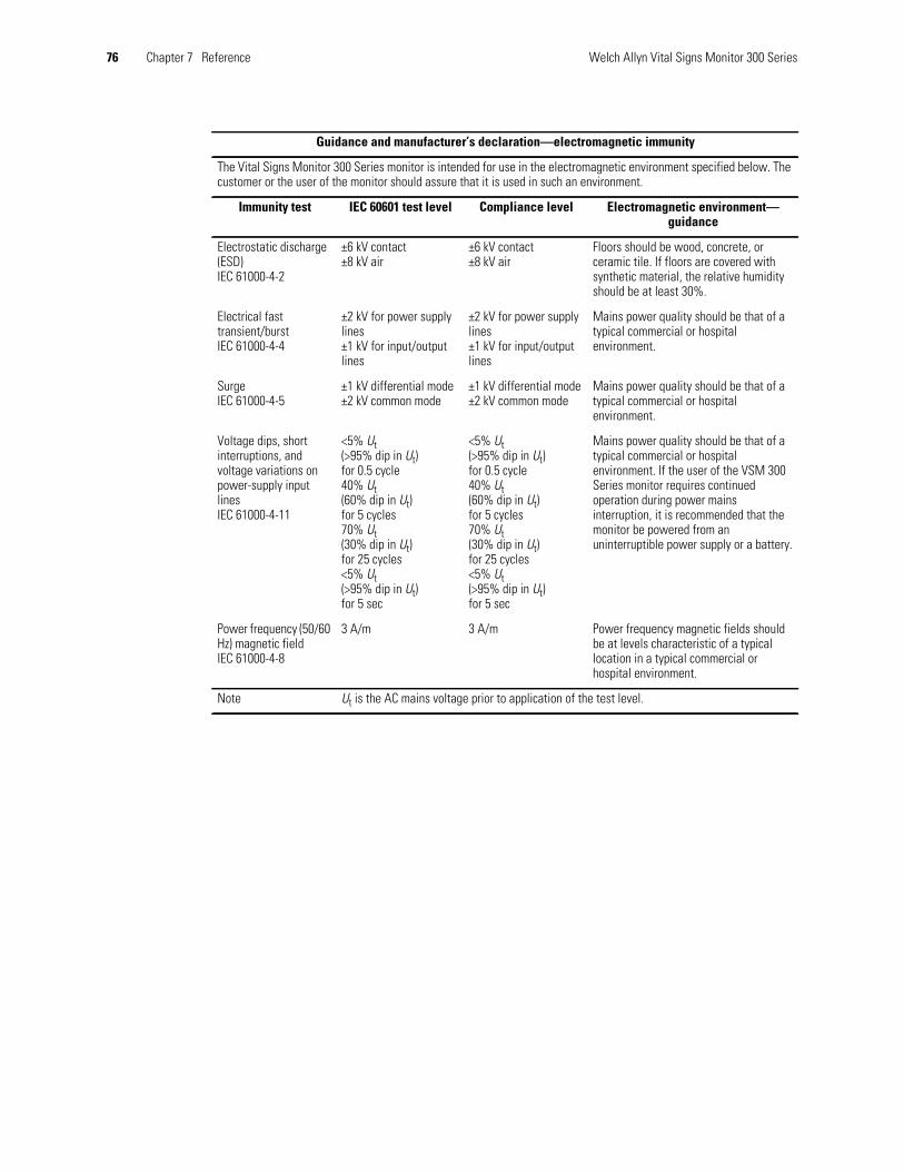
76 Chapter 7 Reference Welch Allyn Vital Signs Monitor 300 Series
Guidance and manufacturer’s declaration—electromagnetic immunity
The Vital Signs Monitor 300 Series monitor is intended for use in the electromagnetic environment specified below. Thecustomer or the user of the monitor should assure that it is used in such an environment.
Immunity test IEC 60601 test level Compliance level Electromagnetic environment—guidance
Electrostatic discharge(ESD)IEC 61000-4-2
±6 kV contact±8 kV air
±6 kV contact±8 kV air
Floors should be wood, concrete, orceramic tile. If floors are covered withsynthetic material, the relative humidityshould be at least 30%.
Electrical fasttransient/burstIEC 61000-4-4
±2 kV for power supplylines±1 kV for input/outputlines
±2 kV for power supplylines±1 kV for input/outputlines
Mains power quality should be that of atypical commercial or hospitalenvironment.
SurgeIEC 61000-4-5
±1 kV differential mode±2 kV common mode
±1 kV differential mode±2 kV common mode
Mains power quality should be that of atypical commercial or hospitalenvironment.
Voltage dips, shortinterruptions, andvoltage variations onpower-supply inputlinesIEC 61000-4-11
<5% Ut(>95% dip in Ut)for 0.5 cycle40% Ut(60% dip in Ut)for 5 cycles70% Ut(30% dip in Ut)for 25 cycles<5% Ut(>95% dip in Ut)for 5 sec
<5% Ut(>95% dip in Ut)for 0.5 cycle40% Ut(60% dip in Ut)for 5 cycles70% Ut(30% dip in Ut)for 25 cycles<5% Ut(>95% dip in Ut)for 5 sec
Mains power quality should be that of atypical commercial or hospitalenvironment. If the user of the VSM 300Series monitor requires continuedoperation during power mainsinterruption, it is recommended that themonitor be powered from anuninterruptible power supply or a battery.
Power frequency (50/60Hz) magnetic fieldIEC 61000-4-8
3 A/m 3 A/m Power frequency magnetic fields shouldbe at levels characteristic of a typicallocation in a typical commercial orhospital environment.
Note Ut is the AC mains voltage prior to application of the test level.
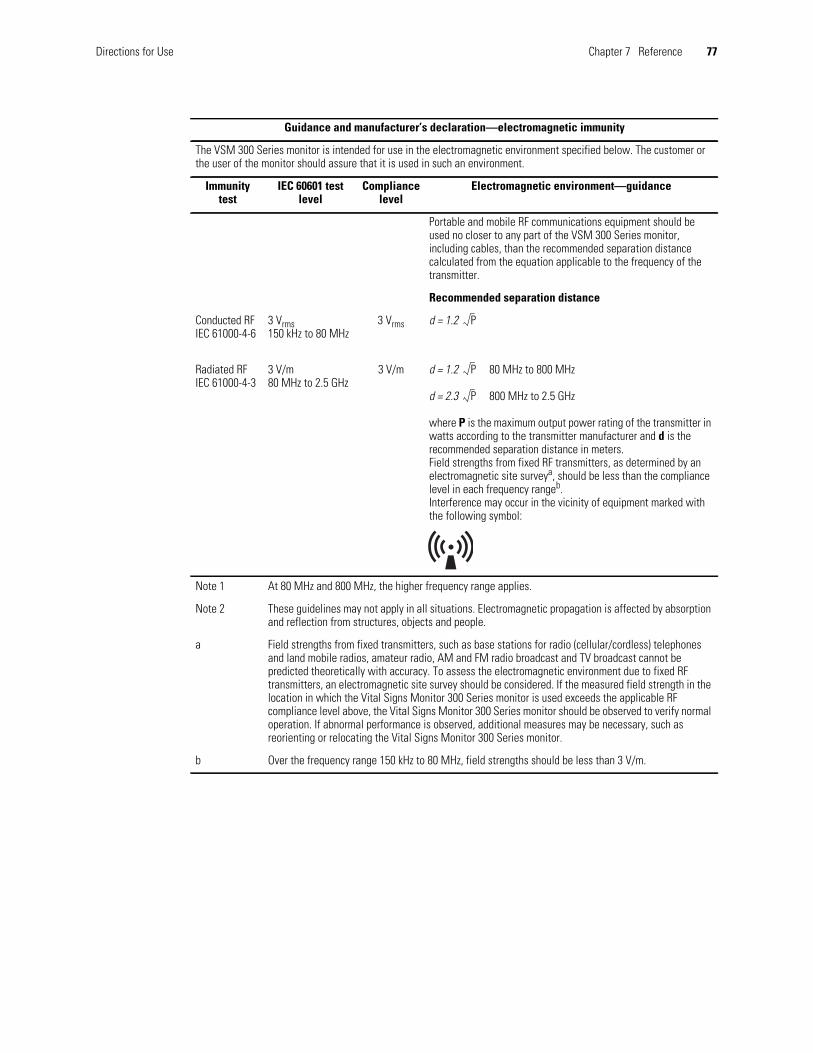
Directions for Use Chapter 7 Reference 77
Guidance and manufacturer’s declaration—electromagnetic immunity
The VSM 300 Series monitor is intended for use in the electromagnetic environment specified below. The customer orthe user of the monitor should assure that it is used in such an environment.
Immunitytest
IEC 60601 testlevel
Compliancelevel
Electromagnetic environment—guidance
Portable and mobile RF communications equipment should beused no closer to any part of the VSM 300 Series monitor,including cables, than the recommended separation distancecalculated from the equation applicable to the frequency of thetransmitter.
Recommended separation distance
Conducted RFIEC 61000-4-6
3 Vrms150 kHz to 80 MHz
3 Vrms d = 1.2
Radiated RFIEC 61000-4-3
3 V/m80 MHz to 2.5 GHz
3 V/m d = 1.2 80 MHz to 800 MHz
d = 2.3 800 MHz to 2.5 GHz
where P is the maximum output power rating of the transmitter inwatts according to the transmitter manufacturer and d is therecommended separation distance in meters.Field strengths from fixed RF transmitters, as determined by anelectromagnetic site surveya, should be less than the compliancelevel in each frequency rangeb.Interference may occur in the vicinity of equipment marked withthe following symbol:
Note 1 At 80 MHz and 800 MHz, the higher frequency range applies.
Note 2 These guidelines may not apply in all situations. Electromagnetic propagation is affected by absorptionand reflection from structures, objects and people.
a Field strengths from fixed transmitters, such as base stations for radio (cellular/cordless) telephonesand land mobile radios, amateur radio, AM and FM radio broadcast and TV broadcast cannot bepredicted theoretically with accuracy. To assess the electromagnetic environment due to fixed RFtransmitters, an electromagnetic site survey should be considered. If the measured field strength in thelocation in which the Vital Signs Monitor 300 Series monitor is used exceeds the applicable RFcompliance level above, the Vital Signs Monitor 300 Series monitor should be observed to verify normaloperation. If abnormal performance is observed, additional measures may be necessary, such asreorienting or relocating the Vital Signs Monitor 300 Series monitor.
b Over the frequency range 150 kHz to 80 MHz, field strengths should be less than 3 V/m.
P
P
P

78 Chapter 7 Reference Welch Allyn Vital Signs Monitor 300 Series
Other Environmental Specifications
Recommended separation distances between portable and mobile RF communications equipment and theVital Signs Monitor 300 Series monitor
The Vital Signs Monitor 300 Series monitor is intended for use in an electromagnetic environment in which radiated RFdisturbances are controlled. The customer or the user of the Vital Signs Monitor 300 Series monitor can help preventelectromagnetic interference by maintaining a minimum distance between portable and mobile RF communicationsequipment (transmitters) and the Vital Signs Monitor 300 Series monitor as recommended below, according to themaximum output power of the communications equipment.
Rated maximum outputpower of transmitter
W
Separation distance according to frequency of transmitter(meters)
150 kHz to 80 MHzd = 1.2
80 MHz to 800 MHzd = 1.2
800 MHz to 2.5 GHzd = 2.3
0.01 0.12 0.12 0.23
0.1 0.38 0.38 0.73
1 1.2 1.2 2.3
10 3.8 3.8 7.3
100 12 12 23
For transmitters rated at a maximum output power not listed above, the recommended separation distance d in meters(m) can be estimated using the equation applicable to the frequency of the transmitter, where P is the maximum outputpower rating of the transmitter in watts (w) according to the transmitter manufacturer.
NOTE 1 At 80 MHz and 800 MHz, the separation distance for the higher frequency range applies.
NOTE 2 These guidelines may not apply in all situations. Electromagnetic propagation is affected by absorption andreflection from structures, objects and people.
P P P
Characteristic Specification
Operating Temperature
SpO2, NIBP, pulse rate, andtemperature measurement
+10 C to +40 C+50 F to +104 F
Operating altitude -170 m to +4877 m-557 ft to + 16,000 ft
Shipping altitude -615 m to 12,300 m-2000 ft to 40,000 ft
Storage temperature -20 C to +50 C-4 F to +122 F
Relative humidity 15% to 90% (non-condensing)

Directions for Use Chapter 7 Reference 79
Nurse Call
Switch current 1A maximum
Switch voltage 30V ac/dc maximum
Isolation 1500 Vrms
Alarm relay Energized during patient alarm
Cable Welch Allyn part number 008-0634-XX, customized to connect to the local Nurse Call system.Cable properties:• 10 feet (3 meters) long.• Not shielded.• One end not terminated (to be customized on site).• One end terminated with a connector which mates to the Nurse Call connector (shown below)
on the monitor.
4 (not connected)1 (Black)Normally Open
3 (Green)Normally Closed
2 (Red) Arm
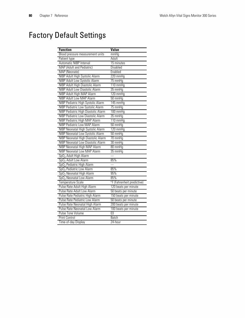
80 Chapter 7 Reference Welch Allyn Vital Signs Monitor 300 Series
Factory Default Settings
Function ValueBlood pressure measurement units mmHgPatient type AdultAutomatic NIBP Interval 15 minutesMAP (Adult and Pediatric) DisabledMAP (Neonate) EnabledNIBP Adult High Systolic Alarm 220 mmHgNIBP Adult Low Systolic Alarm 75 mmHgNIBP Adult High Diastolic Alarm 110 mmHgNIBP Adult Low Diastolic Alarm 35 mmHgNIBP Adult High MAP Alarm 120 mmHgNIBP Adult Low MAP Alarm 50 mmHgNIBP Pediatric High Systolic Alarm 145 mmHgNIBP Pediatric Low Systolic Alarm 75 mmHgNIBP Pediatric High Diastolic Alarm 100 mmHgNIBP Pediatric Low Diastolic Alarm 35 mmHgNIBP Pediatric High MAP Alarm 110 mmHgNIBP Pediatric Low MAP Alarm 50 mmHgNIBP Neonatal High Systolic Alarm 120 mmHgNIBP Neonatal Low Systolic Alarm 50 mmHgNIBP Neonatal High Diastolic Alarm 70 mmHgNIBP Neonatal Low Diastolic Alarm 30 mmHgNIBP Neonatal High MAP Alarm 80 mmHgNIBP Neonatal Low MAP Alarm 35 mmHgSpO2 Adult High Alarm ---SpO2 Adult Low Alarm 85%SpO2 Pediatric High Alarm ---SpO2 Pediatric Low Alarm 85%SpO2 Neonatal High Alarm 95%SpO2 Neonatal Low Alarm 85%Temperature Scale F (Fahrenheit predictive)Pulse Rate Adult High Alarm 120 beats per minutePulse Rate Adult Low Alarm 50 beats per minutePulse Rate Pediatric High Alarm 150 beats per minutePulse Rate Pediatric Low Alarm 50 beats per minutePulse Rate Neonatal High Alarm 200 beats per minutePulse Rate Neonatal Low Alarm 100 beats per minutePulse Tone Volume 03Print Control BatchTime-of-day Display 24-hour

81
Limited WarrantyThis product is sold by Welch Allyn under the warranties set forth in the followingparagraphs. These warranties are extended only to the end-user with respect to theoriginal purchase of this product directly from Welch Allyn or from Welch Allyn’sauthorized distributors.
For two years from the date of the original delivery to the buyer (one year forremanufactured monitors), the Vital Signs Monitor 300 Series is warranted to be free fromfunctional defects in materials and workmanship and to conform in all material respects tothe description of the product contained in the directions for use and other labeling ofthe product.
This warranty is valid only under the following conditions:
• The product is properly operated under conditions of normal use in accordance withapplicable safety and regulatory requirements;
• The product is configured, modified, adjusted and repaired only by Welch Allyn or bypersons expressly authorized by Welch Allyn, in accordance with Welch Allyn’sservice procedures; and
• The product has not been damaged by misuse, negligence, or accident.
For a period of 90 days, unless otherwise specified, this same warranty is made for anyaccessories provided by Welch Allyn.
Under the above warranties, Welch Allyn’s sole and exclusive obligation and buyer’s soleand exclusive remedy is limited to the repair or replacement, at the discretion of WelchAllyn, free of charge, of products found to be defective during the warranty period.Warranty claims must be made, not more than seven days after expiration of the warrantyperiod, by calling the customer service number shown below to obtain a returned materialauthorization number (RMA), and returning the product with the RMA documentation,transportation charges prepaid, to the address specified by Welch Allyn customer service.
Welch Allyn8500 S.W. Creekside PlaceBeaverton, Oregon 97008-7107 USATelephone: (503) 530-7500 or (800) 289-2500Facsimile: (503) 526-4200
Welch Allyn shall not be otherwise liable for any damages, including but not limited toincidental, consequential, or special damages.
No express or implied warranties extend beyond the warranties defined in this document.Welch Allyn makes no warranty of merchantibility or fitness for a particular purpose.

82 Limited Warranty Welch Allyn Vital Signs Monitor 300 Series

83
Index
AAC power
connecting, 9adult
see also patient typedefined, 22icon, 3
alarmhigh and low, 55MAP, 34, 56patient, 51range limits, 56responding to, 51setting, 54tone, 51
alarm limitsrange, 72
alertresponding to, 52
autoclave, 5axillary temperature, 45
Bbatch printing, 27, 60battery
charge before using, 10charging, 9failure, 69low charge warning, 69low power indicator, 10
blood pressureautomatic, 33manual, 32monitoring, 29
buttonsdescription, 8
CCAL message, 32cautions
NIBP, 29
SpO2, 37temperature, 40
CE certification, 2Celsius
units, selecting, 25charging the battery, 9classification, 71cleaning, 67configuration, 16connections
location, 8controls
description, 8CSA certification, 2cuff
positioning, 31pressure, preset, 30selecting, 31
Ddata
erasing, 65default values, 80displays
description, 6
Eequipment alert, 52erasing patient data, 65error codes, 58
Ffactory defaults, 80Fahrenheit
units, selecting, 25FDA, 71
Iindicators

84 Index Welch Allyn Vital Signs Monitor 300 Series
description, 7intended use, 1intravenous infusion
warning, 29
KkPa
units, selecting, 24
Mmaintenance, 67MAP
alarm, 34, 56measurement
data, reviewing, 59units, setting, 24
mmHgunits, selecting, 24
monitorconfiguration, 16setup, 16
monitored temperature, 41, 48monitoring
blood pressure, 29pulse rate, 36SpO2, 37temperature, 40
Nneonatal
see also patient typedefined, 22icon, 3
NIBP, 29automatic, 33cycle, ending, 35manual, 32preparation, 30STAT, 36
nurse callconnector location, 57
Ooperating parameters
setting, 16oral temperature, 43
Ppaper, replacing, 66
patient alarm, 51patient data, reviewing, 59patient type
and alarm limits, 56and cuff size, 31and MAP enable/disable, 23, 36changing, 22selecting, 17setting, 22status indicator, 7
pediatricsee also patient typedefined, 22icon, 3
power, 9power-on self-test, 15predictive temperature, 41printer
output, 61replacing paper, 66
printing patient data, 27programmed limits, 51
RREADING message, 59rectal temperature, 47review, 59
Ssafety
warnings and cautions, 4setup, 9software
license agreement, iispecifications
temperature, 72SpO2
cable connection, 13measuring, 37
STAT interval, 36storage, 67stored data, 59stream printing, 27, 60
Ttemperature
monitoring, 40operating, monitor, 78parameters, setting, 41probe cable connection, 12
trademarks, ii

Directions for Use Index 85
Vvital signs
alarms, 51blood pressure, 29pulse rate, 36SpO2, 37temperature, 40
Wwarnings
general, 4NIBP, 29SpO2, 37temperature, 40

86 Index Welch Allyn Vital Signs Monitor 300 Series