directional speech detector - starkeypro · microphone matching at the time of manufacture ... (or...
TRANSCRIPT

Directional Speech Detector: A Truly Smart Directional Design
Jerry L Yanz, PhD, FAAA
Starkey Laboratories, Inc.
Hearing Research & TechnologyWhite Papers
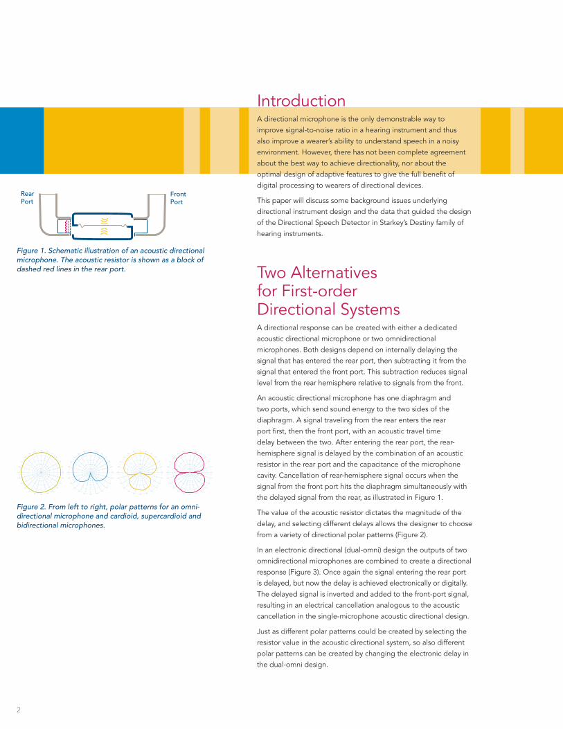
IntroductionA directional microphone is the only demonstrable way to improve signal-to-noise ratio in a hearing instrument and thus also improve a wearer’s ability to understand speech in a noisy environment. However, there has not been complete agreement about the best way to achieve directionality, nor about the optimal design of adaptive features to give the full benefit of digital processing to wearers of directional devices.
This paper will discuss some background issues underlying directional instrument design and the data that guided the design of the Directional Speech Detector in Starkey’s Destiny family of hearing instruments.
Two Alternatives for First-order Directional SystemsA directional response can be created with either a dedicated acoustic directional microphone or two omnidirectional microphones. Both designs depend on internally delaying the signal that has entered the rear port, then subtracting it from the signal that entered the front port. This subtraction reduces signal level from the rear hemisphere relative to signals from the front.
An acoustic directional microphone has one diaphragm and two ports, which send sound energy to the two sides of the diaphragm. A signal traveling from the rear enters the rear port first, then the front port, with an acoustic travel time delay between the two. After entering the rear port, the rear-hemisphere signal is delayed by the combination of an acoustic resistor in the rear port and the capacitance of the microphone cavity. Cancellation of rear-hemisphere signal occurs when the signal from the front port hits the diaphragm simultaneously with the delayed signal from the rear, as illustrated in Figure 1.
The value of the acoustic resistor dictates the magnitude of the delay, and selecting different delays allows the designer to choose from a variety of directional polar patterns (Figure 2).
In an electronic directional (dual-omni) design the outputs of two omnidirectional microphones are combined to create a directional response (Figure 3). Once again the signal entering the rear port is delayed, but now the delay is achieved electronically or digitally. The delayed signal is inverted and added to the front-port signal, resulting in an electrical cancellation analogous to the acoustic cancellation in the single-microphone acoustic directional design.
Just as different polar patterns could be created by selecting the resistor value in the acoustic directional system, so also different polar patterns can be created by changing the electronic delay in the dual-omni design.
Direct signal only
Direct signal plus reverberationReverberation only
CriticaldistanceSi
gna
l Lev
el, d
B
Distance
Pg. 4
100
90
80
70
60
50
40
30
20
10
0
-4 -2 0 2 4 6 8 10 12 14 16
S/N, dB
Per
cent
Co
rrec
t
Pg. 6
Pg. 7 - Top
1 m
SNR ~ 7/8 dB
Pg. 7 - Bottom
1 m
SNR ~ 20 dB
Pg. 8 - Top
1 m
SNR ~ 20 dB
Pg. 8 - Bottom
High Noise@ rear
RearPort
FrontPort
Pg. 1
RearMic
FrontMic
Delay
Pg. 2
Omnidirectional Cardioid Supercardioid Bidirectional
Figure 1. Schematic illustration of an acoustic directional microphone. The acoustic resistor is shown as a block of dashed red lines in the rear port.
2
Figure 2. From left to right, polar patterns for an omni-directional microphone and cardioid, supercardioid and bidirectional microphones.
Direct signal only
Direct signal plus reverberationReverberation only
CriticaldistanceSi
gna
l Lev
el, d
B
Distance
Pg. 4
100
90
80
70
60
50
40
30
20
10
0
-4 -2 0 2 4 6 8 10 12 14 16
S/N, dB
Per
cent
Co
rrec
t
Pg. 6
Pg. 7 - Top
1 m
SNR ~ 7/8 dB
Pg. 7 - Bottom
1 m
SNR ~ 20 dB
Pg. 8 - Top
1 m
SNR ~ 20 dB
Pg. 8 - Bottom
High Noise@ rear
RearPort
FrontPort
Pg. 1
RearMic
FrontMic
Delay
Pg. 2
Omnidirectional Cardioid Supercardioid Bidirectional

Stability of Directional ResponseWhile both of these systems rely on the delay and subtraction of a rear-hemisphere signal entering the rear port, the electronic system has the additional requirement that the two omni microphones be precisely matched in sensitivity and phase. Microphone matching at the time of manufacture and maintenance of that match over time are critical to the effectiveness of dual-omni directional systems.
The difficulty of achieving and maintaining matched microphones present a serious compromise to the performance of a dual-omni directional microphone (Killion, 2004; Trine, 2005). First, directivity index (DI) tends to vary dramatically across devices made with a dual-omni design. Even if microphones are well matched at the time of manufacture, microphone drift over time, caused by changing temperature and humidity, can significantly compromise directional performance (Killion, 2004; Trine, 2005). A mismatch in sensitivity of as little as 0.1 dB reduces DI by 1 dB at 500 Hz (Lin, 2005).
The decision to use an acoustic directional system in the Destiny product line entirely avoids the effects of drift-induced microphone mismatch, ensuring stable directional performance.
The Mythical Benefit of Adaptive NullsSeveral years ago some hearing instrument manufacturers decided to take advantage of the ability to control internal delay and the shape of the resulting polar pattern in dual-omni directional designs. They reasoned that by moving the null of the polar pattern toward a noise source (or jammer), they should be able to maximize the reduction of noise energy. Theoretically, with a jammer located directly to the rear, the greatest noise cancellation should occur with a cardioid pattern; with a jammer to the side a bidirectional pattern should be best. And, of particular note for later discussion, with a diffuse jammer, a supercardioid polar pattern will always be the best solution, since it has the highest DI. By definition DI quantifies the effectiveness of a directional microphone in a diffuse noise environment.
By varying the internal delay between rear and front microphones, the digital signal processor (dsp) can change the polar pattern adaptively from cardioid to supercardioid to bidirectional, looking for the polar pattern that yields the greatest reduction of signal strength. Theoretically it will choose different polar patterns depending on the location of the noise source.
Although on the surface the idea of adaptive polar patterns is appealing, an understanding of real-world acoustics will lead us to question their efficacy. Two points are important in this regard. First, it is relatively rare to encounter an acoustic situation in which there is just one jammer. In fact, most of the situations that present
Figure 3. Electronic (dual-omni) directional microphone system.
3
Direct signal only
Direct signal plus reverberationReverberation only
CriticaldistanceSi
gna
l Lev
el, d
B
Distance
Pg. 4
100
90
80
70
60
50
40
30
20
10
0
-4 -2 0 2 4 6 8 10 12 14 16
S/N, dB
Per
cent
Co
rrec
t
Pg. 6
Pg. 7 - Top
1 m
SNR ~ 7/8 dB
Pg. 7 - Bottom
1 m
SNR ~ 20 dB
Pg. 8 - Top
1 m
SNR ~ 20 dB
Pg. 8 - Bottom
High Noise@ rear
RearPort
FrontPort
Pg. 1
RearMic
FrontMic
Delay
Pg. 2
Omnidirectional Cardioid Supercardioid Bidirectional

difficulties to hearing aid wearers have multiple jammers — restaurants, parties, etc. Second, even if there were only one jammer, the signal from that jammer would be subject to basic acoustic principles, in particular the effect of critical distance.
In any enclosed acoustic space, a signal encounters obstacles that create reflections, which together create a highly homogeneous sound field. The signal at any point in the resulting sound field is the sum of the direct signal from the source plus all of the reflections of that signal. Critical distance (DC) is defined as the distance from a signal source at which the direct signal is equal in level to the reverberant signal (Figure 4). If a listener is closer to the source than DC, the direct sound field dictates the signal level arriving at his ear. If he is outside DC, the reverberant field dictates signal level. Furthermore, in the latter case, the location of the source becomes somewhat unimportant, because the signal is arriving at the ear from many directions simultaneously.
It is here that the idea of adaptive nulls falls apart, because close scrutiny shows that the research supporting adaptive nulls used jammers close to the listener, within the critical distance of the room in which measurements were made (e.g., Bentler et al., 2004a,b; Kuehnel and Checkley, 2000; Powers, 2004; Ricketts and Henry, 2002). It is only in these contrived laboratory situations, in which the jammer arriving at the wearer’s ear is dominated by the direct sound field, that adaptive nulls demonstrate benefit. When jammers are placed outside the critical distance - in situations more like the real world - noise arrives at the ear from diffuse locations, dictated by reflections in the room. In these cases the best solution is always a diffuse, supercardioid, polar pattern (Bentler et al., 2004c; Trine et al., 2004; Trine, 2005; Woods and Trine, 2004; Yanz et al., 2006).
Since most rooms have a critical distance on the order of one meter, it is safe to assume that the vast majority of jammers in the real world are outside DC. In other words, when you encounter difficulties with noise in a restaurant, it is unlikely that there will be only one noise source and even less likely that it will be within three feet of your head. Woods and Trine (2004) and Trine et al. (2004) have shown that in real-world situations, where the jammer is beyond DC, a diffuse polar pattern is always the best directional solution.
4
Direct signal only
Direct signal plus reverberationReverberation only
CriticaldistanceSi
gna
l Lev
el, d
B
Distance
Pg. 4
100
90
80
70
60
50
40
30
20
10
0
-4 -2 0 2 4 6 8 10 12 14 16
S/N, dB
Per
cent
Co
rrec
t
Pg. 6
Pg. 7 - Top
1 m
SNR ~ 7/8 dB
Pg. 7 - Bottom
1 m
SNR ~ 20 dB
Pg. 8 - Top
1 m
SNR ~ 20 dB
Pg. 8 - Bottom
High Noise@ rear
RearPort
FrontPort
Pg. 1
RearMic
FrontMic
Delay
Pg. 2
Omnidirectional Cardioid Supercardioid Bidirectional
Figure 4. Illustration of DC, the point in space at which the direct sound field equals the reverberant sound field.

Starkey’s Directional Speech DetectorBased on the issues discussed above, the Directional Speech Detector in the Destiny product family offers:
• A dedicated acoustic directional microphone in a small modular capsule alongside a dedicated omnidirectional microphone.
• A stable acoustic directional response, unaffected by microphone drift.
• A lower noise floor than dual-omni directional designs.
• Small size to accommodate requests for smaller hearing aid models.
• A diffuse polar pattern to handle diffuse real-world noise conditions.
• A directional design optimized on KEMAR, instead of in a free field, resulting in the highest DI on the market.
• An intelligent set of adaptive switching rules, based on real-world issues and solutions, rather than theoretical expectations without real-world substantiation.
Smart SwitchingWhile adaptive polar patterns have failed the test of real-world efficacy, an alternative form of adaptation in the DSD will help patients with a more straightforward but no less important challenge - deciding when to use directional and when to use omnidirectional mode. Some patients are able to handle the switching decision on their own, but many have difficulty due to limitations of memory or manual dexterity. The DSD uses an elegant switching algorithm to overcome these difficulties.
The DSD uses two measurements and three smart switching rules to govern the decision to switch into or out of directional mode. The switching rules are organized in the following hierarchical rule set.
1. Intelligibility Rule: If switching will improve speech intelligibility, the DSD will switch from omnidirectional to directional mode, or visa-versa.
2. Comfort Rule: If switching will improve listener comfort by reducing noise, the system will switch modes from omnidirectional to directional mode, or visa-versa.
3. Perceptual Stability Rule: If neither intelligibility nor comfort can be improved by switching, the system will maintain its current state to optimize perceptual stability. In other words, it is beneficial to avoid switching when switching has no real benefit.
In this scheme intelligibility takes priority over comfort, and comfort takes priority over perceptual stability. Together, these rules form a sensible and effective approach to the problem of when the system should be in omnidirectional mode and when it should be in directional mode.
5

Direct signal only
Direct signal plus reverberationReverberation only
CriticaldistanceSi
gna
l Lev
el, d
B
Distance
Pg. 4
100
90
80
70
60
50
40
30
20
10
0
-4 -2 0 2 4 6 8 10 12 14 16
S/N, dB
Per
cent
Co
rrec
t
Pg. 6
Pg. 7 - Top
1 m
SNR ~ 7/8 dB
Pg. 7 - Bottom
1 m
SNR ~ 20 dB
Pg. 8 - Top
1 m
SNR ~ 20 dB
Pg. 8 - Bottom
High Noise@ rear
RearPort
FrontPort
Pg. 1
RearMic
FrontMic
Delay
Pg. 2
Omnidirectional Cardioid Supercardioid Bidirectional
Figure 5. Example of percent correct word recognition as a function of SNR.
Speech intelligibility improves rapidly with increasing SNR, at a rate of about 10%/dB, over about a 7-dB range, as shown in Figure 5. Switching from omnidirectional to directional mode can significantly affect intelligibility if the SNR is within this range. However, the function approaches asymptote at high and low values of SNR. Switching into directional mode in this range would offer no benefit.
The DSD algorithm estimates SNR, and if it sees a value in the critical range over which intelligibility can be improved, it switches to the mode that will give the better outcome. On the other hand, if it sees a value of SNR above or below the critical range, where switching will not change performance, it maintains its current state for the sake of maintaining perceptual stability.
The conventional understanding of directional microphones is that they improve signal-to-noise ratio when the hearing aid wearer is looking at the talker, and the jammer is off axis (from the sides or rear). In the example in Figure 6, where signal is seven or eight dB above noise, switching into directional mode reduces the off-axis noise level, improves SNR in the wearer’s ear in the critical range and improves intelligibility.
However, improving SNR does not always improve intelligibility. In the example in Figure 7, with the same signal and noise locations as the previous example but a high SNR, switching into directional mode would have no effect, since the ambient SNR is well into the asymptotic region of the function. In this case the DSD algorithm stays in omnidirectional mode.
In a third example (Figure 8) the room is mostly quiet, except for one talker off to the side, whom the hearing aid wearer would like to hear. (Imagine a conference room.) A simple comparison of omni versus directional microphone output would show greater power in the omni microphone, suggesting that directional mode would be helpful by reducing signal from the rear hemisphere. Obviously this would be an erroneous conclusion, which would reduce the desired off-axis speech. The DSD in the Destiny products, however, uses its SNR statistic to recognize the signal as speech with no significant competing noise, and stays in omnidirectional mode to maintain audibility of that signal.
In some situations speech comprehension is not the major goal of the adaptive algorithm. Hearing aid wearers encounter some high-noise situations in which they are not conversing with anyone. In these situations comfort takes priority. They just want relief from the noise. In such cases if the DSD does not see a significant speech input (low SNR) and sees that comfort in noise can be improved by switching modes, it will do so.
In Figure 9, for example, the hearing aid wearer in the easy chair is surrounded by noise, and the noise at the rear is higher than the rest. The DSD algorithm sees the opportunity to improve comfort and switches into directional mode to give relief from the high noise in the rear. Notice that the algorithm would have reached a different conclusion if it saw a usable speech signal (higher SNR).
6
Figure 6. Desired speech signal at the front (tan loud-speaker) in a diffuse noise field (blue loudspeakers), with SNR of 7 to 8 dB. DSD decision: Switch to directional mode to improve intelligibility.
Direct signal only
Direct signal plus reverberationReverberation only
CriticaldistanceSi
gna
l Lev
el, d
B
Distance
Pg. 4
100
90
80
70
60
50
40
30
20
10
0
-4 -2 0 2 4 6 8 10 12 14 16
S/N, dB
Per
cent
Co
rrec
t
Pg. 6
Pg. 7 - Top
1 m
SNR ~ 7/8 dB
Pg. 7 - Bottom
1 m
SNR ~ 20 dB
Pg. 8 - Top
1 m
SNR ~ 20 dB
Pg. 8 - Bottom
High Noise@ rear
RearPort
FrontPort
Pg. 1
RearMic
FrontMic
Delay
Pg. 2
Omnidirectional Cardioid Supercardioid Bidirectional
Figure 7. Desired signal (tan loudspeaker) at the front in a diffuse noise field (blue loudspeakers), with SNR of 20 dB. DSD decision: Stay in omnidirectional mode to maintain perceptual stability.
Direct signal only
Direct signal plus reverberationReverberation only
CriticaldistanceSi
gna
l Lev
el, d
B
Distance
Pg. 4
100
90
80
70
60
50
40
30
20
10
0
-4 -2 0 2 4 6 8 10 12 14 16
S/N, dB
Per
cent
Co
rrec
t
Pg. 6
Pg. 7 - Top
1 m
SNR ~ 7/8 dB
Pg. 7 - Bottom
1 m
SNR ~ 20 dB
Pg. 8 - Top
1 m
SNR ~ 20 dB
Pg. 8 - Bottom
High Noise@ rear
RearPort
FrontPort
Pg. 1
RearMic
FrontMic
Delay
Pg. 2
Omnidirectional Cardioid Supercardioid Bidirectional

If the listening environment is such that neither intelligibility nor comfort can be improved by switching modes, the DSD remains in its current mode. The governing principle here is that the brain relies on sensory predictability. For this reason the threshold at which the DSD switches into directional mode is offset from the threshold at which it switches back into omnidirectional mode. The resulting hysteresis tends to keep the system in one mode until ample evidence exists to indicate that switching is beneficial.
The success of any adaptive algorithm depends on two principles. First, it should adapt only when doing so will be beneficial to the wearer. Second, the adaptation must be smooth and artifact-free to minimize any perceptual disruption. The adaptive decision criteria and time course of the Directional Speech Detector algorithm - and of all of the adaptive algorithms of the Destiny product line - adhere strictly to these design principles.
ConclusionA great deal of planning, data collection and hardware and software development have gone into the creation of the Directional Speech Detector. Starkey is confident that the resulting combination of features - low noise, small size, high directivity index modeled on KEMAR, excellent stability achieved by an acoustic directional microphone, and a smart hierarchical set of adaptive switching rules - will prove to make the Destiny directional design the best in class among the top tier of advanced digital hearing instruments.
7
Figure 8. Speech from rear hemisphere at a level well above the noise in the room. DSD decision: Remain in omnidirectional mode to optimize speech signal level from rear hemisphere.
Direct signal only
Direct signal plus reverberationReverberation only
CriticaldistanceSi
gna
l Lev
el, d
B
Distance
Pg. 4
100
90
80
70
60
50
40
30
20
10
0
-4 -2 0 2 4 6 8 10 12 14 16
S/N, dB
Per
cent
Co
rrec
t
Pg. 6
Pg. 7 - Top
1 m
SNR ~ 7/8 dB
Pg. 7 - Bottom
1 m
SNR ~ 20 dB
Pg. 8 - Top
1 m
SNR ~ 20 dB
Pg. 8 - Bottom
High Noise@ rear
RearPort
FrontPort
Pg. 1
RearMic
FrontMic
Delay
Pg. 2
Omnidirectional Cardioid Supercardioid Bidirectional
Figure 9. Noise surrounding hearing aid wearer is stronger at the rear. DSD algorithm decision: Switch to directional mode to improve comfort.
Direct signal only
Direct signal plus reverberationReverberation only
CriticaldistanceSi
gna
l Lev
el, d
B
Distance
Pg. 4
100
90
80
70
60
50
40
30
20
10
0
-4 -2 0 2 4 6 8 10 12 14 16
S/N, dB
Per
cent
Co
rrec
t
Pg. 6
Pg. 7 - Top
1 m
SNR ~ 7/8 dB
Pg. 7 - Bottom
1 m
SNR ~ 20 dB
Pg. 8 - Top
1 m
SNR ~ 20 dB
Pg. 8 - Bottom
High Noise@ rear
RearPort
FrontPort
Pg. 1
RearMic
FrontMic
Delay
Pg. 2
Omnidirectional Cardioid Supercardioid Bidirectional

Starkey Laboratories, Inc. 6700 Washington Avenue South Eden Prairie, MN 55433
Toll Free: 1–800–328–8602 Fax: 952–828–6974
www.starkey.com
© 2006 Starkey Laboratories, Inc. 79636-00 05/06 WTPR9636-00-EE-ST
ReferencesBentler, RA, Egge, JLM, Tubbs, JL, Dittberner, AB, and Flamme,
GA (2004c), Quantification of directional benefit across different polar response patterns. Journal of the American Academy of Audiology, 15:649-659.
Bentler, R. A., Palmer, C., & Dittberner, A. B. (2004a). Hearing-in-noise: comparison of listeners with normal and (aided) impaired hearing. Journal of the American Academy of Audiology, 15(3), 216-225.
Bentler, R., J. Tubbs, J.L., Egge, J.L.M., Flamme, G.A., and Dittberner, A.B. (2004b). Evaluation of an adaptive directional system in a DSP hearing aid. American Journal of Audiology, 13: 73-79.
Kuehnel, V. and P. Checkley (2000). Advantages of an adaptive multi-microphone system. The Hearing Review, May: 58-60, 74.
Killion, M. C. (2004). Myths about hearing in noise and directional microphones. The Hearing Review, February 2004: 14, 16, 18-19, 72-73.
Lin, W. (2005), Noise and directionality. Starkey internal document.
Powers, T. A. (2004). Proving adaptive directional technology works: a review of studies. The Hearing Review, April, 46, 48-49, 69.
Ricketts, T., & Henry, P. (2002). Evaluation of an adaptive, directional-microphone hearing aid. International Journal of Audiology, 41, 100-112.
Trine, T.D. (2005). Custom directional hearing aids: State of the art. The Hearing Professional, March-April.
Trine, T.D., Olson, L., Ioannou, M., Banerjee, S., and Woods, W.A. (2004). Directional benefit for noise within or outside the critical distance. Presentation at the American Auditory Society, March 2004.
Woods, WS, and Trine, TD (2004), Limitations of theoretical benefit from an adaptive directional system in reverberant environments. Acoustics Research Letters Online 5(4), October.
Yanz, JL. Panelists challenge “conventional wisdoms” on hearing aid design. The Hearing Journal, 59:3, 2006, 36-44.