directional drilling 1 espanol
TRANSCRIPT

���������������� ��
���� ��������������������������
��
�� ����
��
�
���� ����
����
���� ����

140_MasterHandout_rev19 Sp
Perforación Direccional I Curso # 140
Descripción del Curso Este curso de nivel introductorio de 5 días de Perforacion Direccional Basico más 2 dias adicionales de Basico de Motores de Perforacion se concentra en el marco de los conocimientos fundamentales que un Perforador Direccional debe poseer de modo que pueda perforar efectivamente un pozo de una geometría simple. El curso provee de una instrucción en aula de clases sobre la política de la compañía, procedimientos, papeleo reglamentario, cálculos direccionales, terminología de la perforación direccional, funcionamiento de los instrumentos direccionales y sus aplicaciones, motores de lodo (tipos, configuraciones y aplicaciones), y sobre el manejo básico del software WELLZ y FIRST Serán administradas evaluaciones y tareas periódicamente y un examen escrito al final (el 5to dia) de la completacion del Curso de Perforacion Direccional. Mas un examen de motores de perforación el 7mo dia Prerrequisitos: Este curso presupone que los estudiantes que lo toman ya vienen con conocimientos de matemáticas básicas (algebra y trigonometría), Procedimientos de Windows Operativo, y tienen tres (3) meses o mucho mas de experiencia previa en direccionamiento de pozos como perforadores direccionales en entrenamiento. Contenido del Curso: Primer Día
• Introducción o Procedimientos en el sitio del Pozo
• Introducción a la Perforación Direccional o Pozos Verticales o Pozos Direccionales
Slants (Inclinados) Build and Hold (construir y mantener) Tipos S Rango Extendido Horizontales con Patas Sencilla o Multiples
• Aplicaciones de la Perforación Direccional
o Limitaciones de la Perforacion Direccional o Metodos de Deflectar un Pozo
Principio de Diseños • Fuerzas Laterales • Principio de la Palanca

140_MasterHandout_rev19 Sp
• Peso sobre la barrena / mecha (WOB) • Torque Reactivo
Whipstock ( Cuña/Cuchara) Ensambles de Chorros “Jetting” Ensambles de Fondo Rotacionales
• Ensambles de Construir / Fulcrum • Ensambles de Caer / Pendulares • Ensambles de Mantener / Empacados
Ensambles de Fondo • Configuraciones Principales • Rotar versus Deslizar
• Motores de Perforación o Introduccion a los Motores de Fondo
• Funcionamiento • Componentes del Motor
• Dump Sub / Valvala Hidraulica de Viajes • Power Section / Seccion de Pode • Drive Assembly / Ensamble de Transmision • Adjustable Assembly ( adjustable) • Bearing Section (Rodamientos)
o Motor Handbook Introduction • Nomenclatura convencional de los Motores • Especificaciones de los Motores • Calculos y Graficos de Desempeno de los Motores • Limitaciones Operacionales & de la perforacion • Especificaciones y Graficos de desempeno de los Motores
• Determinar RPM, Torque, Full Load, Maxima Presion Diferencial • Especificaciones de Torque de Armado • Procedimientos de configuración del ajuste 3/4° • Especifications del torque de armado del MWD
• Trigonometría
o Definiciones de Seno, Coseno, Tangente o Triangulos Rectos y Teorema de Pitagoras o Conversiones de Coordenadas Polares/Rectangulares
• Funcionamiento del Calculador HP48GX (cuando este disponible) o Entrada Basica de Datos y Operaciones o Procedimiento de calculo de Survey con el metodo del angulo promedio
• Perforación Bajo Balance

140_MasterHandout_rev19 Sp
Segundo Día Evaluación#1
• Introducción a los Registros Direccionales (Surveys) y a las Mediciones Mientras se Perfora (MWD)
o Definiciones • Inclinacion, Direccion del Hoyo (Acimut), Desvio (Inclinacion),
Profundidad Medida, Tool face Magnetico, Tool face High side/Gravitacional
o Campos Magnetico y Gravitacional • Fuerza del Campo Gravitacional Local • Fuerza del Campo Magnetico Local • Angulo de la Pendiente Magnetica Local • Componentes Horizontales y Verticales del Campo Magnetico Local
o Correcciones al Survey Direccional • Correccion de la referencia al Norte Verdadero (Declinacion) • Correccion de la referencia al Norte de la Grilla/Cuadricula
(Convergencia) • Descripcion del Sistema de Coordenadas del Survey
o Exactitud del MWD y del Survey Direccional • Especificaciones de la Precision del Sistema de Survey • Factores que afectan la Precision de la Inclinacion
• Falla de Equipo • Inestabilidad de los Vectores de la Gravedad • Calibracion Fuera de las Especificaciones • Precision del Sensor
• Factores que afectan la Precision del Acimut • Inestabilidad de los Vectores de la Gravedad (usados en los calculos del acimut) • Falla de Equipo • Inestabilidad de los Vectores Magneticos (Calculo del espaciado No Magnetico - Monel) • Calibracion Fuera de las Especificaciones • Precision del Sensor
• Factores Adicionales que afectan la Precision del Survey • Latitud, Inclinacion, Acimut del Pozo • Una incorrecta aplicacion de la Correccion Magnetica • Desalineamiento del BHA en el agujero • Resolucion de la Transmision del MWD en Tiempo-Real
o Chequeo de la Calidad del Survey • Tolerancias de Btotal y Gtotal

140_MasterHandout_rev19 Sp
o Conversiones Formato de la Direccion del Hoyo • Calculos de la conversion de modo Cuadrante/Acimut
o Conversiones de tipos de Co-ordinadas • Calculos de la conversion de coordenadas Polares/Rectangulares
• Demostración de los Componentes de un MWD ( si se dispone) • Introducción a los “Slide Sheets” (Hojas de Registro de Deslizado)
o Calculos Basicos usando el ejemplo propuesto o Determinar el slide requerido en el punto de Arranque (Kick-Off Point) o Calcular el slide visto hasta la estacion de survey o Calcular el desempeno del motor (output: tasa del motor) o Extrapolar el survey hasta la mecha o Determine el slide requerido a partir del resultado obtenido en la proyeccion
• Método de Calculo de Surveys del Angulo Promedio
o Determinar el Largo del Courso, los Promedios de la Inclinacion y el Acimut, la Profundidad Vertical Verdadera (TVD), el Desplazamiento, la Latitud, el Departure, el Cierre (Closure), y la Vertical Section (VS)
Tercer Día Evaluación#2
• Software de Reportes FIRST o Proceso de configuracion del Trabajo/Job & Entradas de Data
o Estandar de comportamiento, procedimientos, expectativa de la compania, costeo • Demostración de una Instrumento de Survey Single Shot (si se dispone)
o Procedimiento de Ensamblaje y Prueba o Corriendo el ensamble de S.Shot
� Requerido del Espaciamiento del Compass o Ejercicio del Proceso Operacional
� Recarga de la pelicula � Develado y lectura del disco de la pelicula
o Torque Reactivo

140_MasterHandout_rev19 Sp
• Cálculos del Tool Face Offset (OTF)
o Offsets Internos (G4 / Precision Pulse) o Offsets Externos (OTF del Drill Collar)
� Procedimiento de Calculo del OTF o Aplicacion del Offsets para cada sistema de MWD/LWD o Pantallas entrada de los OTF en el Software de MWD/LWD o Ejercicio de Simulacion del OTF
� Hoja de Verificacion del OTF • Mediciones dimensionales de las herramientas
o Generacion del diagrama de pesca de las herramientas o El uso de los anillos de calibracion
Cuarto Día Evaluación#3
• Demostración de la Perforación de un Pozo Direccional con el Software de Survey WELLZ
o Cargar la propuesta � Verificar las coordenadas del pozo, del objetivo y la información relevante
del pozo o Configurar un Nuevo archivo de surveys
� Informacion del Encabezado / Header � Centro del Campo / Field Center � Configurar el o los obejtivos / target(s) � Seleccion del punto de Amarre / Tie-on Point � Mover la Profunfidad/Rotar el Pozo ( Depth shifting, rotate well )
o Graficos – Vista planta y seccion (Plan and Section View) o Nomenclatura de los archivos o Ajustes de las Elevaciones : Ground Level (GL) y el Kelly Bushing (KB) o Configurar el slide sheet o Simular la perforacion de un pozo direccional simple
� Usar una propuesta real • Patear el pozo de la vertical (kick-off ), y mantenga hasta la TD
� Entrar nuevos surveys en Wellz � Actualzar el slide sheet � Entrar la extrapolacion a la mecha en Wellz � Visualizar el perfil del pozo mediante el modulo de graficos en Wellz

140_MasterHandout_rev19 Sp
� Determinar el slide requerido teorico usando el “estimated average motor output” � Referenciar el slide sheet real con el teorico obtenido � Demonstrar el analisis logico para determininar las acciones correctivas entre las estaciones de survey � Discutir el valor de la planeacion adelante de la mecha “planning ahead of bit”, y las consecuencias de “estar delante /being ahead” o de “estar detrás / “being behind" de la linea, y las consideraciones de la formacion
• Martillos de Perforacion & Aceleradores
Quinto Día
• Revisión del material y Preguntas • EXAMEN FINAL ESCRITO de DD-1 y EXAMEN FINAL PRACTICO de Slide Sheets
y Diagrama Dimensional de Pesca Sexto Dia
• Curso Basico de Motores de Perforacion y Operaciones con Motores de Fondo para Perforadores Direccionales
Septimo Dia
• Demostración de Ensamblaje de un Motor de Lodo (si se dispone / o video) • EXAMEN de Motores de Perforacion

© 2006 Weatherford. All rights reserved.
Directional Drilling IArribo a la Locación
Revision 4

© 2006 Weatherford. All rights reserved.
1- Chequearse con el company man
• Introduzcase
• Pregunte e infórmese acerca de:
– Cuando el servicio se necesitará o comenzará?
– Qué actividad esta actualmente realizando el rig?
– Dónde esta previsto el alojamiento?
– Dónde se establecera su centro de trabajo o ubicacion de la cabina?

© 2006 Weatherford. All rights reserved.
2 – Chequeo de las Herramientas
• Mida fisicamente las herramientas
• Chequee y registre todas las conecciones
• Verifique que todas las piezas esten en locación
• Verifique que todas las conecciones de las herramientassean las apropiadas.
• Chequee que tenga en sitio todas las conecciones - XO para armar el BHA con los DP y HW del Rig.

© 2006 Weatherford. All rights reserved.
3 – Revise las Necesidades con el Company Man
• Verifique que la propuesta que tiene el company man coincida con la suya
• Verifique la licencía del pozo y las coordenadas de superficie y asegurese que sean las mismas
• Coincide el pozo con el que tiene en los plots impresos (aseguresede tener todas las copias)
• Compare la elevacion del terreno y la del KB del Rig con company man. Asegurese de las cifras que se van a usar esten claras y todosla comprendan
• Confirme el emplazamiento del Jar
• Confirme la Mecha (Bit) y los chorros a usar

© 2006 Weatherford. All rights reserved.
Directional Drilling IBásico de Perforación Direccional
Revision 5

© 2006 Weatherford. All rights reserved.
Introducción a la Perforación Direccional
• La Perforación Direccional se define como la practica de controlar la dirección y la desviación del hoyo del pozohacia un objetivo subterraneo predeterminado.

© 2006 Weatherford. All rights reserved.
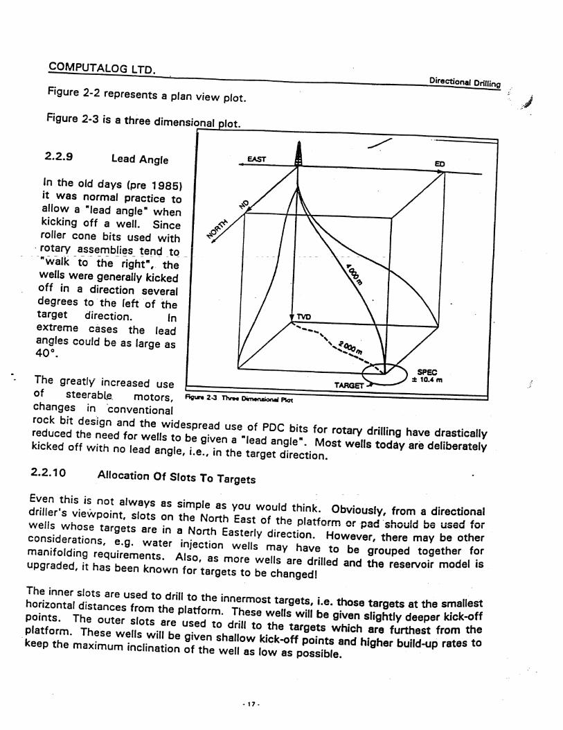
Progreso en la Perforación Direccional
1980’sS-Wells
RelativamenteSimple
ActulidadComplejos
Multilaterales Horizontales
© 2006 Weatherford. All rights reserved.
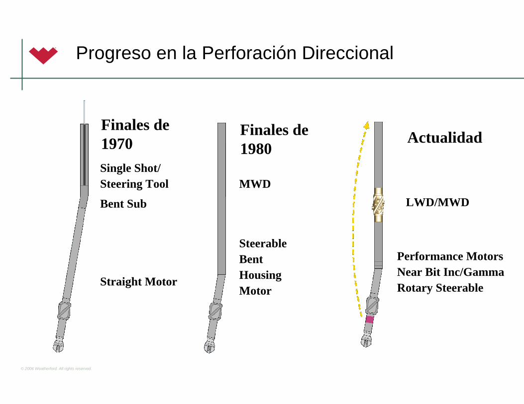
Progreso en la Perforación Direccional
Finales de 1970 ActualidadFinales de
1980Single Shot/Steering Tool
Bent Sub
Straight Motor
MWD
SteerableBentHousingMotor
LWD/MWD
Performance Motors Near Bit Inc/GammaRotary Steerable

© 2006 Weatherford. All rights reserved.
Herramientas de Perforación Direccional
– Herramientas de Perforación
– Sistemas de Surface logging
– Servicios de Surveying/orientation
– Steerable motors
– Instrumented motors for geosteering applications
– At-bit inclination and gamma ray
– Rotary Steerable

© 2006 Weatherford. All rights reserved.
Limitaciones de la Perforación Direccional
• Doglegs (Maximum well curvature)– Establece el cliente, desempeño del motor, componentes del BHA
• Torque Reactivo (Rotación de la sarta en contrasentido del Reloj)– Dificulta el mantenimiento o fijacion del Tool Face del ensamble
• Drag (Arrastre por Friccion entre el hoyo y el BHA)– Aumenta con la profundidad y la inclinacion
• Hidraulica (Presión de Circulación)– La maxima presión operativa del rig y el equipo, ECD
• Limpieza del Hoyo (Caracteristicas del Fluido y el ambiente del Flujo)– Remoción de Cortes
• Peso sobre la Mecha / Weight on Bit (Carga aplicada a la mecha durante la perforación)– Regulación de la presión diferencial para la optima ROP y vida de la mecha
• Estabilidad del Hoyo (Habilidad fisica del hoyo para mantenerse abierto)– Caracteristicas Fisicas de la Formacion, fallas mobiles etc

© 2006 Weatherford. All rights reserved.
Tipos de Pozos Direccionales
• Caracterizados por el perfil del pozo
– Verticales(Controlados)
– Slant / Inclinados
– Build and Hold (J-Well / tipo J)
– Build, Hold and Drop (S-Well/ tipoS)
– Horizontales
– Extended Reach

© 2006 Weatherford. All rights reserved.
Tipos de Pozos Direccionales
• Tipo S-Curve

© 2006 Weatherford. All rights reserved.
• Pozos Horizontales
– Short Radius / Radio Corto
• 2°-3°/Foot Build Rates
• Equipo Especializado
– Flexible Collars - Tubing
– Medium Radius / Radio Medio
• 10°-22°/100’ Build Rates
• Ensambles de Double Bend
– Long Radius / Radio Largo
• 1.5°-6°/100’ Build Rates
• Ensambles Navegables
• Shorter radius well = less lateral section
Short Radius
45' 200'
Medium Radius
300' 2,000'
Long Radius
1,400' 4,000'
Tipos de Pozos Direccionales

© 2006 Weatherford. All rights reserved.
Aplicaciones de la Perforación Direccional
• Multiples pozos desde una estructura offshore
• Control de la verticalidad de pozos
• Pozos de Alivio (Relief wells)

© 2006 Weatherford. All rights reserved.
Aplicaciones de la Perforación Direccional
• Extended-Reach Drilling / Rango Extendido
– Remplazo de pozos submarinos y desarrollo de yacimientos offshore desde menos plataformas
– Desarrollo de Campos Costaneros desde Tierra Adentro
– Reduccion del impacto ambientalal desarrollar campos desde emplanadas o clusters / pads

© 2006 Weatherford. All rights reserved.
Aplicaciones de la Perforación Direccional
• Sidetracking
• Localizaciones Inaccesibles

© 2006 Weatherford. All rights reserved.
Aplicaciones de la Perforación Direccional
• Perforación bajo Balance / Underbalanced Drilling
– Cuando la presión Hidrostática o la de circulaciónhoyo abajo ejercida por el fluido de perforacián esmantenida por debajo de la presión de poro de la formación.
– Beneficios
• Minimiza el skin damage
• Reduce los incidentes de pérdidas de circulacióny de pegas o atasco de tuberia
• Aumenta la ROP mientras extende la vida de la mecha (Bit)
• Reduce o elimina la necesidad de costososprogramas de estimulación
• El pozo puede ser producido mientras de perfora(IPR)

© 2006 Weatherford. All rights reserved.
Elementos de Desviacion
• Técnicas y Herramientas para desviar el curso del pozode una manera controlada
– Kick-off, nudge (levantar angulo desde la vertical en la direccion deseada )
– Correccion de Trayectorias (giro, levante, caida hacia la trayectoria deseada)
– Sidetrack (desvia el pozo de su trayectoria original

© 2006 Weatherford. All rights reserved.
Metodos para Deflectar un Hoyo
• Operaciones con Whipstock
– Aún en uso
• Jetting / Chorros
– Raramente usado hoy dia, pero valido y barato, en formacionesblandas
• Ensambles Convencionales de Perforación Rotaria
– Build, Drop, Hold / Construir, tumbar y Mantener Angulo
• Ensambles Navegables / Steerable Assemblies (Mud Motors)
– De mayor uso, rápido y preciso
• Rotary Steerable
– Rotación continua de la sarta mientras se orienta y perfora

© 2006 Weatherford. All rights reserved.
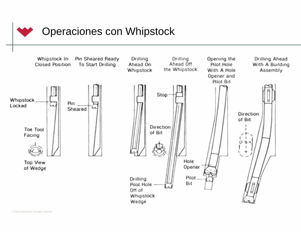
Elementos de Desviacion: Cuchara
• Usada en formaciones medianamente duras o duras
• Orientada con cara direccional
• Cuchara es puesta a fondo y el pin es roto
• Un hoyo piloto de diametro mas pequeno al original es necesario
• Solo se perfora una flecha/kelly antes de sacary cambiar de sarta
• El hoyo piloto es ampliado y luego se repite el proceso
© 2006 Weatherford. All rights reserved.
Operaciones con Whipstock
© 2006 Weatherford. All rights reserved.
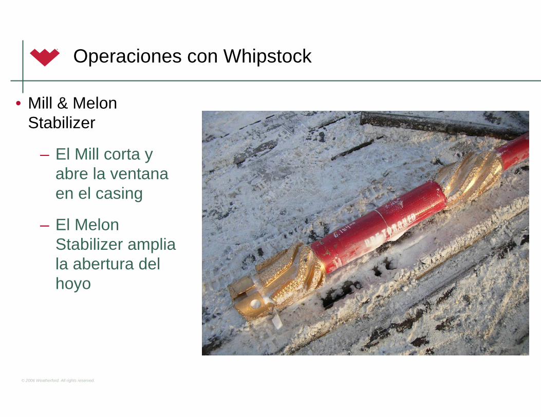
Operaciones con Whipstock
• Mill & Melon Stabilizer
– El Mill corta y abre la ventanaen el casing
– El Melon Stabilizer ampliala abertura del hoyo
© 2006 Weatherford. All rights reserved.
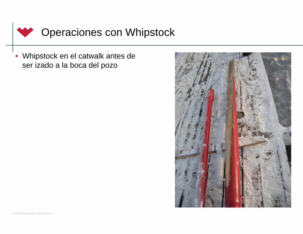
Operaciones con Whipstock
• Whipstock en el catwalk antes de ser izado a la boca del pozo
© 2006 Weatherford. All rights reserved.
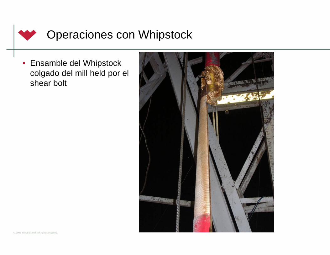
Operaciones con Whipstock
• Ensamble del Whipstockcolgado del mill held por el shear bolt

© 2006 Weatherford. All rights reserved.
Operaciones con Whipstock
• Extremo Inferior del whipstockmostrando el plunger ( buzo) extendido y el troquel en posicionretractil (no disparado / unfired)

© 2006 Weatherford. All rights reserved.
Whipstock Operations
• Bottom end of whipstock showing retracted plunger and dies in set (fired) position

© 2006 Weatherford. All rights reserved.
Elementos de Desviacion: Jetting
• Usada en formaciones suaves
• Tipicamente emplea una mecha de chorros especial (o una de tri-conos normal)
• Una tobera grande orientada a la direccion deseada (Dos de los tres chorros (jets or nozzles) tienen pequeño diametro, y un tercero es mucho más grande)
• Una doble caja estabilizada y sarta lisa
• Lava y hace un bolsillo en la formacion. El hoyo se socavarápreferentemente en la direccion del chorro mayor
• Empuja y Desliza hasta levantar el angulo
• Continua perforando rotando como una sarta convencional
• Correcciones de rumbo son mas dificiles a medida que la inclinacion aumenta

© 2006 Weatherford. All rights reserved.
Jetting / Chorros
• Diseño simple pero podria ser tediosode implementar en el Rig
– El Build rate varia dependiendode las caracteristicas de la formación (podria generardoglegs extremadamente altos)
– Cambios en la tasa de flujo, en el proceso de sliding, etc. podrian producir resultadosinesperados

© 2006 Weatherford. All rights reserved.
Ensambles Convencionales de Perforación Rotaria
• Diseñados para controlar el desvio (inclinación) del pozodurante la perforación rotaria (normal)
• Usa el principio de control del comportamiento del BHA de perforación rotaria
– Side Forces / Fuerzas Laterales
– Weight on Bit / Peso sobre la mecha
– Stabilization / Estabilización
– Fulcrum Principle / Principio de la Palanca

© 2006 Weatherford. All rights reserved.
Ensambles Convencionales de Perforación Rotaria
• Side Force
– Es la fuerza en la mecha resultante del pandeo de la tuberia al aplicar WOB
– FS = Bi * SC * 3.0
LT3
– Bi : distancia desplazada por la interferencia del pandeo (in.)
– SC : stiffness coefficient / coeficiente de rigidéz (lb-in2)
– LT : distancia axial sobre la cual el pandeo ocurre (in.)

© 2006 Weatherford. All rights reserved.
Ensambles Convencionales de Perforación Rotaria
• Efecto del PSM / Weight on Bit (WOB)
– Las cargas axial creadas por el weight on bit produce fuerzas de pandeo /doblez entre el estabilizador y la mecha
– El diámetro del hoyo, el diámetro del collar, el calibre del estabilizador y su ubicación en el BHA determinarán comoel PSM ( weight on bit ) se va a concentrar en esta y lasmagnitud de las fuerzas laterales resultantes

© 2006 Weatherford. All rights reserved.
Ensambles Convencionales de Perforación Rotaria
• Aumento del Weight on Bit = Incremento del Build Rate

© 2006 Weatherford. All rights reserved.
Ensambles Convencionales de Perforación Rotaria
• Estabilizador– Dispositivo adicionado al BHA con OD similar al del hoyo– Diseñado para:
• Ayudar a concentrar el PSM (weight on bit)• Minimizar el pandeo y las vibraciones• Reducir el torque (fricción) de la perforación por medio de disminuir
el contacto del collar con las paredes del hoyo• Ayudar a prevenir el atascamiento por diferencial y el key seating
( ojo de llave o cerradura)

© 2006 Weatherford. All rights reserved.
Principios de Estabilizacion
BHA#1Rotatorio
Convencional
BHA#2Sarta
Navegable
BHA#3Sarta Navegable
Rotatoria
Contruir
Mantener
Caer
Orientar Tool Face & con el fin de dirigir el Pozo
Empuje ó fuerzaslaterales en la Barrena

© 2006 Weatherford. All rights reserved.
Estabilización
El Estabilizador en el BHA está diseñado para subir, mantener ó caer la inclinación. Elementos críticos:
Posición del Estabilizador en el BHA.Diam.Ext. de los Drill Collars, peso de la sarta y momento de Inercia.Inclinación del Pozo.PSB, RPM, gasto.Tamaño del Agujero.Tipo de BarrenaDiámetro del Estabilizador ó tamaño de las aletas
Problemas de la predicción (Efectos de la Formación, Giro del Pozo, cavernas en el pozo.…)

© 2006 Weatherford. All rights reserved.
Efectos de la Ubicación de los Estabilizadores
Ubicación de Estabilizadores y resultado de fuerzas laterales.

© 2006 Weatherford. All rights reserved.
Estabilización
Lev Mant Caer Caer<
Posicion de los Estabilizadores en la Sarta determinan lasfuerzas laterales resultantes

© 2006 Weatherford. All rights reserved.
Ensambles Convencionales de Perforación Rotaria
• Tipos de Ensambles de Perforación Rotaria
– Clasificación por el efecto sobre la inclinación del hoyodurante la perforación
• Fulcrum / Palanca (build / construir)
• Pendulum (drop / tumbar)
• Packed / Empacado o Rígido (hold / mantener)
• Los ensambles de Rotación NO permiten el control de la dirección del pozo (azimuth)

© 2006 Weatherford. All rights reserved.
Ensambles Convencionales de Perforación Rotaria
• Ensambles Fulcrum (Build / Construir)
– Un estabilizador insertado en la sarta justo encimade la mecha actua como apoyo o pivote
– El drill collar encima del estabilizador actua comopalanca
– Al aplicar peso / WOB provocara que el drill collar se doble/pandee (bow/buckle)
– Encima de 5o inclinación el collar se pandea haciala cra baja del hoyo (por gravedad)
– Empujando a la mecha fuertemente contra la parte alta del hoyo, creando una tendencia a construirángulo o inclinación debido a las fuerzas lateralespositivas en la mecha
© 2006 Weatherford. All rights reserved.
Ensambles Convencionales de Perforación Rotaria
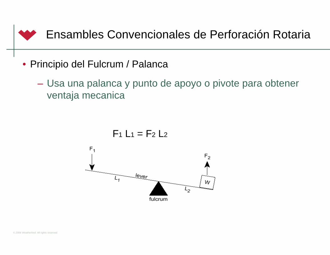
• Principio del Fulcrum / Palanca
– Usa una palanca y punto de apoyo o pivote para obtenerventaja mecanica
F1 L1 = F2 L2

© 2006 Weatherford. All rights reserved.
Ensambles Convencionales de Perforación Rotaria
• Posición del Fulcrum
– A mayor cercania a la mecha, mayores serán las fuerzaslaterales generadas para un diametro de drill collar dado
© 2006 Weatherford. All rights reserved.
Ensambles Convencionales de Perforación Rotaria
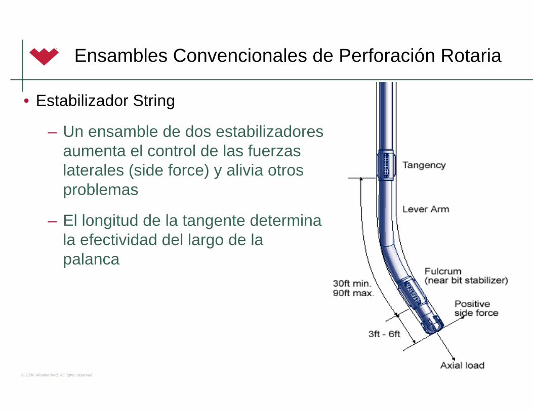
• Estabilizador String
– Un ensamble de dos estabilizadoresaumenta el control de las fuerzaslaterales (side force) y alivia otrosproblemas
– El longitud de la tangente determinala efectividad del largo de la palanca

© 2006 Weatherford. All rights reserved.
Ensambles Convencionales de Perforación Rotaria
Alta-
Alta -
Alta -
Media -
Media -
Media -
Low -
• Respuesta del el Ensamble de Construir / Build Assembly

© 2006 Weatherford. All rights reserved.
Ensambles Convencionales de Perforación Rotaria
• Técnicas para el aumento de la tendencia a construir– Incrementar el WOB
• Incrementar la flexibilidad del collar – Reducir las RPM en la mesa
• Disminuir la tendencia de los collares a mantenerse derechos– Disminuir la tasa de flujo
• Reducir el socavamiento (washout) de la formación– Trabajar la tuberia y/o menos rotación
• Preservar los doglegs perforados en la formación– Circulara fuera de fondo (off-bottom)
• Reducir el washout

© 2006 Weatherford. All rights reserved.
Ensambles Convencionales de Perforación Rotaria
• Ensanbles Pendulares (Tumbar/Caer)
• Principio del Péndulo
• El estabilizador encima de la mecha es removido y se añade un drill collar adicional, haciendo el ensamblede fondo menos flexible
• Un estabilizador por encima del collar, apropidamente ubicado, evita que este drill collar se recueste en el lado bajo del hoyo
• La fuerza gravitacional actua sobre la parte inferior del collar y la mecha, causando queel hoyo pierda o disminuya el angulo
• Incrementando el largo de la tangente, y el peso del drill collar, y/o la rigidez del collar ampliara la tendencia a tumbar de esteensamble de fondo

© 2006 Weatherford. All rights reserved.
Ensambles Convencionales de Perforación Rotaria
Alta -
Media -
Baja-
• Respuesta de Ensambles de Tumbar / Drop Assembly
© 2006 Weatherford. All rights reserved.
Ensambles Convencionales de Perforación Rotaria
• Técnicas para Incrementar la Tendencia a Tumbar Angulo ( Drop Tendency) – Disminuir el WOB
• Reduce la flexibilidad del collar – Aumentar las RPM en la mesa
• Aumenta la tendencia de los collares a permanecer derechos– Aumenta la tasa de flujo
• Aumenta el socavamiento o washout de la formación– Trabajar rotar la sarta tanto como sea posible
• Socava/reduce las pata de perro (dog leg) perforados– Circular en el fondo
• Incrementa el washout

© 2006 Weatherford. All rights reserved.
Ensambles Convencionales de Perforación Rotaria
• Ensambles de Mantener ángulo : Hold (Packed/ Empacado o Rígido)
– El ensamble empacado/rígido se usa para mantener el ángulo
– Multiplicar la cantidad de estabilizadores emplazados en puntos especificos espaciados de forma regular paracontrolar la sarta minimizando la desviacion del hoyo
– El aumento de la rigidéz en el BHA al adicionarestabilizadores previene a la sarta del pandeo y fuerza a la mecha a ir derecho adelante

© 2006 Weatherford. All rights reserved.
Ensambles Convencionales de Perforación Rotaria
Alta -
Alta -
Alta -
Medio-
Baja -
• Respuesta del Ensamble Empacado/Rígido (Hold / Mantener)

© 2006 Weatherford. All rights reserved.
Elementos de Desviacion: Motores de Fondo
• Poder hidráulico traducido en mecánico en la barrena
• La tuberia se mantiene estacionaria y se desliza el motor
• Codo en el motor provee fuerza lateral a la barrena
• Desvia la trayectoria del pozo de la vertical, sidetracks, corridas de correccion, etc.
• Mas efeciente comparada con métodos de deflección tradicionales como cucharas, jetting, etc.

© 2006 Weatherford. All rights reserved.
Ensambles Navagables (Mud Motors)
• Motores de Fondo: ComDrill™ y PrecisionDrill™

© 2006 Weatherford. All rights reserved.
Ensambles Navagables (Mud Motors)
• Aplicaciones
– Hoyos rectos / Straight-Hole
– Directional Drilling / Sidetracking
– Horizontal Drilling
– Re-entry Wells
– Underbalanced Wells / Air Drilling
– Cruce de Rios o Bahias / River Crossings

© 2006 Weatherford. All rights reserved.
Ensambles Navagables (Mud Motors)
• Mud Motor
– Requiere de flujo de liquido/gas para generar torque para girar la mecha
– Contiene un ensamble mecanico que permite el ajuste del angulo bend / defleccion del motor
– Al aumentar la severidad del bend se aumenta la tendencia a construirdel motor
– Inherentemente el bend permite al perforador directional controlar la cara del motor (tool face) desde la superficie al orientar la mesa rotariadel Rig (operación sliding)
• ComDrill™ es el diseño original de Computalog de rodamientos de camarasellada lubricados con aceite
• PrecisionDrill™ es el diseño de Precision con rodamientos de camaraabierta lubricados por el lodo

© 2006 Weatherford. All rights reserved.
Rotary Steerable
• Revolution™ Rotary Steerable System (RSS)

© 2006 Weatherford. All rights reserved.
Rotary Steerable
• Permite el control direccional completo mientras se perfora rotando toda la sarta al deflectar el arbol del dispositivo dentro de una camara de pistones hidraulicos
• Beneficios
– La ausencia del sliding reduce el riesgo de pandeo de la tuberia
– La rotación continua de la sarta reduce el chance atascamiento por diferencial
– Reduce la fricción por torque & drag ( torsion y arrastre) debido a que genera un perfil curvo mas sueve, reduce la rugosidad del hoyo
– Posibilita la perforación de secciones alargadas de extended reach wells, horizontales y laterales
– Mejora la evaluación de las formaciones debido a la mejoria del contacto de los pads de la herramientas de wireline, y de LWD (menos stand off effect)
– Control de la Desviación en pozos verticales

© 2006 Weatherford. All rights reserved.
Rotary Steerable
• La tecnologia del sistema Revolution™ es la llamada “Point-the-bit” que usa un estabilizadorpivote entre la mecha y la unidad mecanicapara orientar el eje axial de la mecha con la del eje de direccion requerida del hoyo
• La rotación relativa entre el arbol de giro(driveshaft), (el cual trasnmite el torque a la mecha) y la camisa no rotativa mueve unabomba hidraulica
• Esta bomba genera una fuerza motriz internasuficiente para deflectar el arbol de giro en la orientación que se requiere para dirigir el pozohacia el objetivo dado

© 2006 Weatherford. All rights reserved.
PUSH POINT
Rotary Steerable
• Calidad del Hoyo

© 2006 Weatherford. All rights reserved.
CCáálculolculo del del PuntoPunto NeutroNeutro ((PozoPozo Vertical)Vertical)
– Es el punto donde la tuberia pasade estar en compresion a tension
– Asegurarse que se encuentre yasea en la sarta o DC’s
– Drill Collars y HWDP son utilizadospara asegurarse que exista peso suficiente para perforar
Lpn (Punto Neutro) = WOB / W x FF

© 2006 Weatherford. All rights reserved.
CCáálculolculo de de PuntoPunto NeutroNeutro ((PozoPozo DesviadoDesviado))
– La inclinación debe ser tomada en cuenta
– Para un pozo con un ángulo de 45 gradossolo el 71% del peso de la sarta está disponiblepara utilizar

© 2006 Weatherford. All rights reserved.
PuntoPunto NeutroNeutro
• En pozos desviados:
– Lpn (Punto Neutro) = Peso Requerido / (FF/Cos Incl. a PT)
FF = Factor de Flotación = ( 1 – Peso Lodo(ppg) / 65.5)

© 2006 Weatherford. All rights reserved.
ConsideracionesConsideraciones en el en el disediseññoo de de SartasSartas– DC’s para adicionar/quitar peso
• Más peso para barrenas tricónicas
• Menos peso para barrenas PDC
– Minimizar los DC’s en pozos de alta inclinación
– Minimizar los estabilizadores para evitar colgaduras mientrasse desliza
– El diseño de la sarta es importante cuando existe un granporcentaje de perforación rotando
– La agresividad de la barrena PDC debe ser compensadapara encajar con la capacidad de torque del motor
– Hidraulicas y/o gasto suficiente: limpieza, lubricacion, y torque en el motor
– La caida de presión en la barrena para limpiar y flujopara lubricar los cojinetes del motor de fondo

© 2006 Weatherford. All rights reserved.
Planeación de un Pozo Direccional
• Geología
• Completación y Producción
• Limitaciones de la Perforación

© 2006 Weatherford. All rights reserved.
Geología
• Litologia que se atraviesa en la perforación
• Estructuras Geologicas que se perforarán
• Tipo de target que el geologo espera alcanzar
• Localización de los topes/horizontes de agua y gas
• Tipos de pozos (gas o aceite)

© 2006 Weatherford. All rights reserved.
Completación y Producción
• Tipo de completación requirida (“frac job”, bomba electrosub o balancin/cabillas, etc.)
• Requerimientos de la completación por recuperación mejorada(Enhanced recovery)
• Requerimientos de emplazamiento del Hoyo para futurosplanes de producción y drenaje
• Temperatura y Presión de Fondo

© 2006 Weatherford. All rights reserved.
Limitaciones de la Perforación
• Selección de la ubicación superficial y diseño del pozo
• Conocimiento o experiencia previa de perforación en el area e identificación de areas problematicas en particular

© 2006 Weatherford. All rights reserved.
Limitaciones de la Perforación
• Dimensiones del Casing y profundidadesde asentamiento
• Dimensiones del Hoyo
• Fluidos de perforación requeridos
• Capacidad del taladro (rig) y sus equipos
• Longitud de la seccion o el tiempo que se requiere para realizar el servicio direccional
• Influencia del tipo de instrumento de survey y la trayectoria del pozo
© 2006 Weatherford. All rights reserved.
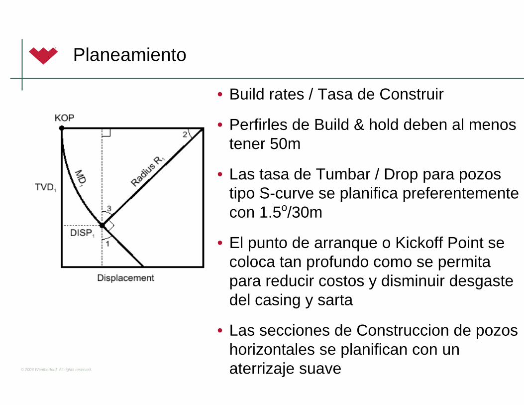
Planeamiento
• Build rates / Tasa de Construir
• Perfirles de Build & hold deben al menostener 50m
• Las tasa de Tumbar / Drop para pozostipo S-curve se planifica preferentementecon 1.5o/30m
• El punto de arranque o Kickoff Point se coloca tan profundo como se permitapara reducir costos y disminuir desgastedel casing y sarta
• Las secciones de Construccion de pozoshorizontales se planifican con un aterrizaje suave
© 2006 Weatherford. All rights reserved.
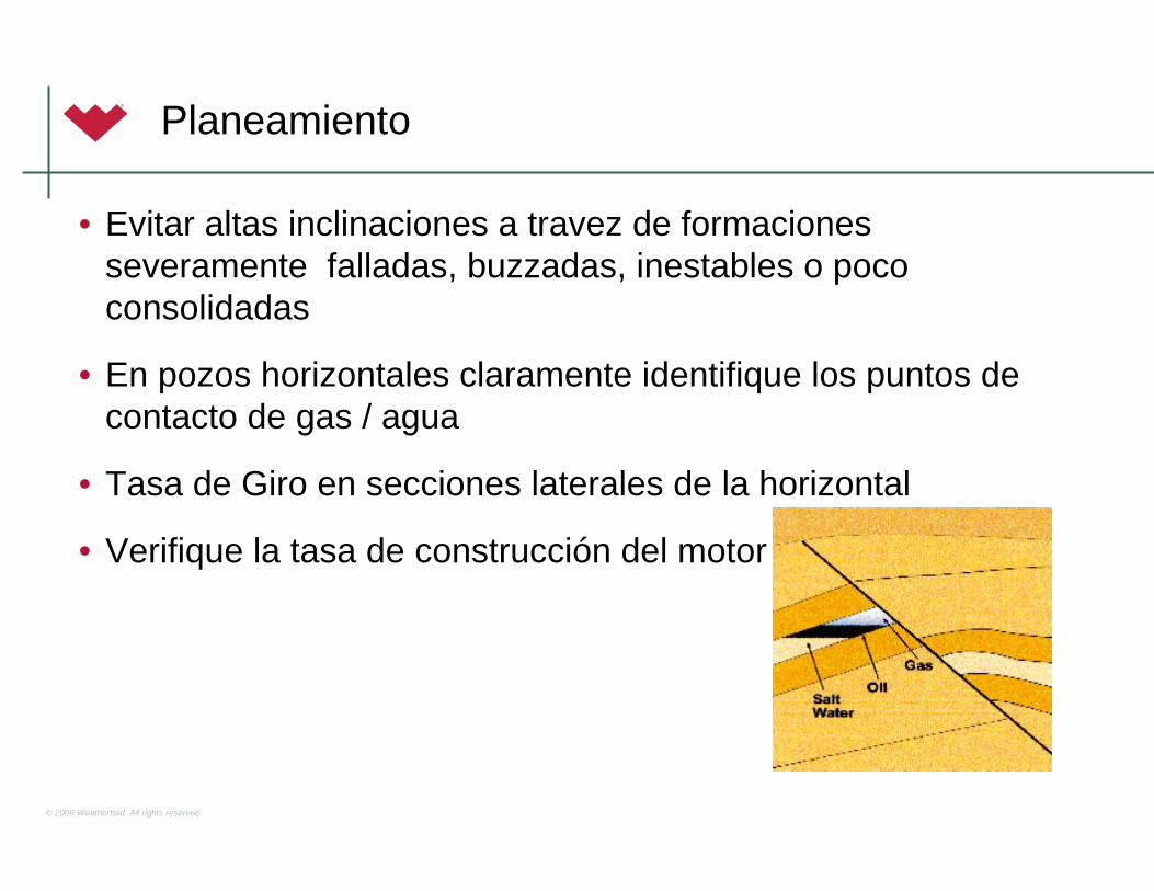
Planeamiento
• Evitar altas inclinaciones a travez de formacionesseveramente falladas, buzzadas, inestables o pococonsolidadas
• En pozos horizontales claramente identifique los puntos de contacto de gas / agua
• Tasa de Giro en secciones laterales de la horizontal
• Verifique la tasa de construcción del motor

© 2006 Weatherford. All rights reserved.
Planeamiento
• Donde sea posible comience el sidetrack al menos a 20m fuera del casing
• La severidad del Dogleg podria se aproximadamente de 14o/30m saliendo con un whipstock
• Identifique todos los pozos dentro de los 30m de la trayectoria propuesta del pozo y conduzca una verificacionde anticolision

1
© 2006 Weatherford. All rights reserved.
Directional Drilling IDrilling Motors
Revision 8
© 2006 Weatherford. All rights reserved.
Tipos de Drilling Motor
Positive Displacement MotorTurbine Motor
2
© 2006 Weatherford. All rights reserved.
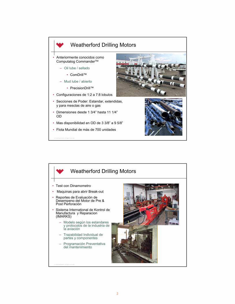
Weatherford Drilling Motors
• Anteriormente conocidos comoComputalog CommanderTM
– Oil lube / sellado
• ComDrill™
– Mud lube / abierto
• PrecisionDrill™
• Configuraciones de 1:2 a 7:8 lobulos
• Secciones de Poder: Estandar, extendidas, y para mesclas de aire o gas
• Dimensiones desde 1 3/4” hasta 11 1/4”OD
• Mas disponibilidad en OD de 3 3/8” a 9 5/8”
• Flota Mundial de más de 700 unidades
© 2006 Weatherford. All rights reserved.
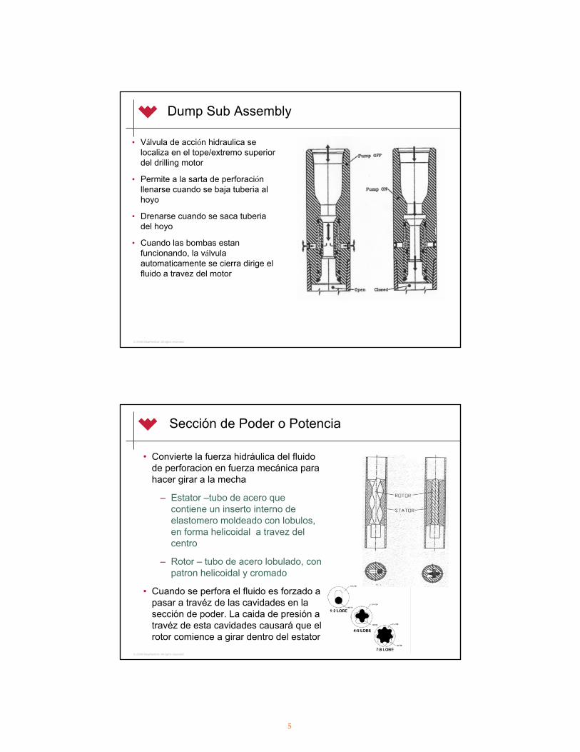
Weatherford Drilling Motors
• Test con Dinamometro
• Maquinas para abrir Break-out
• Reportes de Evaluación de Desempeno del Motor de Pre & Post Perforación
• Sistema International de Kontrol de Manufactura y Reparacion(IMARKS)
– Modelo según los estandaresy protocolos de la industria de la aviación
– Trazabilidad Individual de partes y componentes
– Programación Preventativadel mantenimiento

3
© 2006 Weatherford. All rights reserved.
Weatherford Drilling Motors
• Desarrollo, manufactura, y servicios a motores de fondo por más de veinte años
• Extremadamente confiable - experiencia operacionalsobrepasa las 120,000 horas cada año
• El Grupo de Drilling Tools en Edmonton, Canada obtubo la certificación ISO 9001: 2000
• El alcance de la certificación incluye:
– Diseño, desarrollo y ensamble de drilling motors
– Reparación y mantenimiento de MWDs y herramientas de fondo
g1
© 2006 Weatherford. All rights reserved.
Investigación & Desarrollo de Drilling Motor
• Desarrollo de Nuevas Tecnologias
– Alto Torque - Alto Flujo (aguas profundas / deep water)
– Prototipo de Thin Wall Motor (menos elastomero)
- Soporte Técnico
- Análisis de fallas
- Prueba y ensayo de Productos

Slide 5
g1 gomezj2, 5/29/2008

4
© 2006 Weatherford. All rights reserved.
Aplicaciones de los Drilling Motor
• Straight - Hole
• Directional Drilling / Sidetracking
• Horizontal Drilling
• Re - entry Wells
• Underbalanced Wells / Air Drilling
• River Crossings / Cruce de Rios
© 2006 Weatherford. All rights reserved.
Componentes de los PDM Motors
• Dump Sub
• Power Section
• Drive Assembly (CV)
• Adjustable Assembly
• Bearing Assembly1/2
5/6 7/8
3/42/3
9/10
5
© 2006 Weatherford. All rights reserved.
Dump Sub Assembly
• Válvula de acción hidraulica se localiza en el tope/extremo superior del drilling motor
• Permite a la sarta de perforaciónllenarse cuando se baja tuberia al hoyo
• Drenarse cuando se saca tuberiadel hoyo
• Cuando las bombas estanfuncionando, la válvulaautomaticamente se cierra dirige el fluido a travez del motor
© 2006 Weatherford. All rights reserved.
Sección de Poder o Potencia
• Convierte la fuerza hidráulica del fluidode perforacion en fuerza mecánica parahacer girar a la mecha
– Estator –tubo de acero quecontiene un inserto interno de elastomero moldeado con lobulos, en forma helicoidal a travez del centro
– Rotor – tubo de acero lobulado, con patron helicoidal y cromado
• Cuando se perfora el fluido es forzado a pasar a travéz de las cavidades en la sección de poder. La caida de presión a travéz de esta cavidades causará que el rotor comience a girar dentro del estator
6
© 2006 Weatherford. All rights reserved.
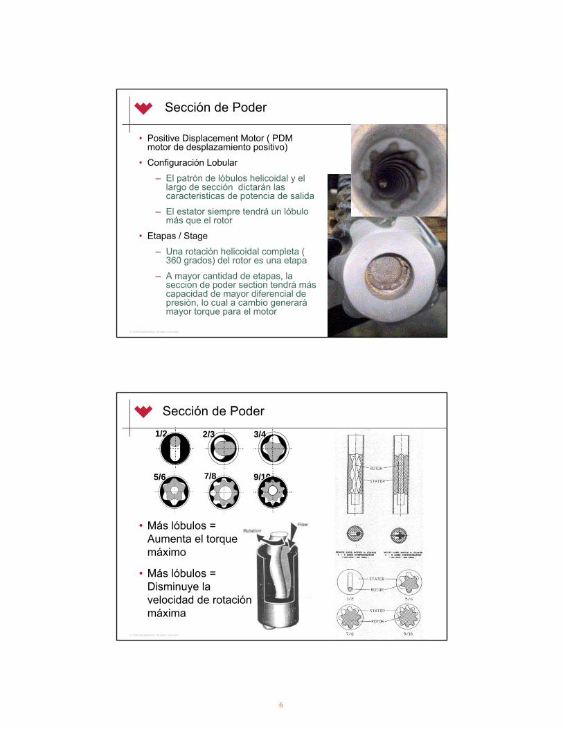
Sección de Poder
• Positive Displacement Motor ( PDM motor de desplazamiento positivo)
• Configuración Lobular
– El patrón de lóbulos helicoidal y el largo de sección dictarán lascaracteristicas de potencia de salida
– El estator siempre tendrá un lóbulomás que el rotor
• Etapas / Stage
– Una rotación helicoidal completa ( 360 grados) del rotor es una etapa
– A mayor cantidad de etapas, la seccion de poder section tendrá máscapacidad de mayor diferencial de presión, lo cual a cambio generarámayor torque para el motor
© 2006 Weatherford. All rights reserved.
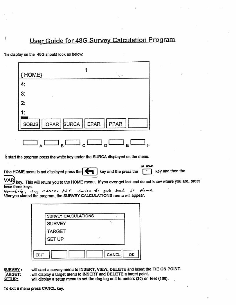
Sección de Poder1/2
5/6 7/8
3/42/3
9/10
• Más lóbulos = Aumenta el torque máximo
• Más lóbulos = Disminuye la velocidad de rotaciónmáxima

7
© 2006 Weatherford. All rights reserved.
Selección del Motor
• Estas son la tres configuraciones de motores más comunes, lascuales proveen un amplio rango de velocidades y respuestas de salida de torque requeridos para satisfacer una multitud de aplicaciones de la perforación
© 2006 Weatherford. All rights reserved.
Ensamble de Conducción / Drive Assy
• Convierte la rotación eccéntrica del rotor en concéntrica
Universal Joint
Flex Rod
Constant Velocity Joint

8
© 2006 Weatherford. All rights reserved.
Ensamble Ajustable
• De dos grados y de tres grados
• Ajustable en el campo con incrementos hasta obtener el ángulo bend máximo
• Usado en conjunto con el Drive Assembly
• Provee un amplio rango de tasas potenciales de construcción en pozosdireccionales y horizontales
H = 1.962 o
© 2006 Weatherford. All rights reserved.
Ensamble de Rodamientos / Bearing Assembly
• Transmitela carga axial y radial de la mecha a la sarta de perforación
• Thrust Bearing
• Radial Bearing
• Oil Reservoir
• Balanced Piston
• High Pressure Seal
• Bit Box Connection
• Existe tambien el
tipo de mud lubed

9
© 2006 Weatherford. All rights reserved.
Mud Lube Versus Oil Lube Motors
•Los motores de rodamientos lubricados poraceite sellados ha experimentado unapopularidad ganada por la confiabilidad y mejoraen los materiales sobre previos diseños
•Los motores de rodamientos lubricados por lodose desarrollaron como complemento de la flota de oil lubes. En condiciones optimas de minimocontenidos de solidos y baja erosion muestrandesempeños mejores de MTBF y son más fácilesde serviciar
© 2006 Weatherford. All rights reserved.
• Dos generaciones de mud lubricated motors
• Mientras el resto de la industria sostiene una flota de más de 10 años de diseño de mud lubricated motor, Weatherford diseño su primer ML motor desde 0 en el 2001
• Ha obtenido ya un trazo impresionante de records –casos de corridas superiores a 400 horas continuas.
Mud Lube Versus Oil Lube Motors

10
© 2006 Weatherford. All rights reserved.
Beneficios de los Mud Lubricated motors
• Tasas predecibles de desgaste
• Rango de Temperatura Operativa Elevadas
• Simplicidad del servicio
• Simplicidad de la operación. Menor cantidad de partes
• No problemas con la invasion de fluido
© 2006 Weatherford. All rights reserved.
Motores Especiales

11
© 2006 Weatherford. All rights reserved.
Motor Handbook
• Todas la posiblesconfiguraciones de motoresesta representada en el Motor Handbook
– Información Dimensional
– Especificaciones
– Configuracion del Housing Adjustable
– Tablas de Desempeño / Performance Charts
© 2006 Weatherford. All rights reserved.
Data Dimensional del Motor

12
© 2006 Weatherford. All rights reserved.
Especificaciones del Motor
© 2006 Weatherford. All rights reserved.
Tasas de Construcción Estimadas / Est. BR
Kick Pad/Stab Below Adjustable
Kick Pad/Stab + Stab on Top Sub

13
© 2006 Weatherford. All rights reserved.
Tablas de Desempeño / Performance Charts
© 2006 Weatherford. All rights reserved.
Uso de los Performance Charts
• Differential Pressure / Presión Diferencial
– La diferencia de presion del sistema cuando el motor esta en fondo (loaded/cargado) y cuando el motor esta fuera de fondo(not loaded/ no cargado)
• Full Load / Plena Carga
–Indica la máxima presión diferencial operativa recomendada del motor
• RPM
–Las RPM Motor se determinan al entrar la presion diferencial y proyectar verticalmente hasta interceptar la linea apropiada de la tasa de flujo
• Torque
–El torque del Motor se determina al entrar la presion diferencial нproyectar verticalmente hasta interceptar la linea de torque

14
© 2006 Weatherford. All rights reserved.
Probando el desempeño del Motor
© 2006 Weatherford. All rights reserved.
Historia de Partes/Componentes del Motor

15
© 2006 Weatherford. All rights reserved.
Reporte de Servicio del Motor
© 2006 Weatherford. All rights reserved.
Limitaciones Operacionales del Motor
• Temperatura
• Peso sobre la Mecha (WOB)
• Rotación del Motor vs Angulo de Ajuste (Bend angle)
• Fluido de Perforación
• Presión Diferencial del Motor
• Perforación Bajo Balance (Under-balanced Drilling-UBD)

16
© 2006 Weatherford. All rights reserved.
• Temperatura– Maxima temperatura operativa estandar 219 °F / 105 °C
– El estator puede ser personalizado para temperaturas de hasta300 °F / 150 °C
– Se usan materiales y dimensiones especiales de los componentes
• PSM (WOB)– La carga excesiva sobre la mecha detiene la rotacion a causa de
que la seccion de poder del motor no es capaz de proveersuficiente torque a travez de esta (Paralizacion/acorralamiento del Motor o en ingles Motor Stalling)
– El rotor no puede girar dentro del estator, formando un sello queaumentara la presión (tambien se conoce como represionamientodel motor
– De continuar la circulación en esta condición se erosionará el estator y se desprenderá el elastómero (stator chunk)
Limitaciones Operacionales del Motor
© 2006 Weatherford. All rights reserved.
• Rotación del Motor vs Angulo de Ajuste (Bend angle)– La rotación con un bend angle mayor a 1.83 grado no se recomienda (produce
fatiga y daños en el cuerpo del motor)– La velocidad de rotación no deberá exceder 60 RPM (excesiva carga ciclica
sobre el cuerpo del motor)– No existe limite de RPM para un motor recto (sin ángulo de ajuste)
• Fluido de Perforación– Diseñado para operar practicamente con todo tipo de fluidos como agua fresca y
salada, base a aceite, lodos con aditivos para controlar la viscosidad o lasperdidas de circulación, o con gas nitrogeno
– Se recomienda el realineado o recontrucción de los estatores que trabajen en fluidos agresivos como los basados en hidrocarburos que pueden ser dañinospara el elastómero
• Lodo emulsion Invertida, Envirovert, Enviro-drill, Cutter-D, Underbalanced Diesel, Diesel, Native Crude, Drill Sol, Nitrogen, Potassium Silicate, Oil, Pureoil 2000, Aphron
– El alto contenido de chlorines puede causar daños internos a los componentes– Mantener el contenido de solidos debajo de 5%– Mantener el contenido de arena debajo de 0.5%
Limitaciones Operacionales del Motor

17
© 2006 Weatherford. All rights reserved.
• Presión Diferencial
– Diferencia entre la presion del sistema cuando el motor se encuentraen fondo (bajo carga) y fuera de fondo (sin carga)
– Una caida de presión excesiva a travéz del rotor y estator causará un desgaste prematuro (chunking), o un desempeño pobre
• Under-balanced Drilling (UBD / CPD)– Una proporción adecuada de gas/liquido debe ser usada para evitar
daños al motor (siempre necesita parte liquida para enfriar y lubricar)
– Bajo condiciones de alta presión, el gas nitrógeno puedepenetrar/permear hacia la goma del estator y expandirse cuando se viaja fuera del hoyo causando el hinchado y erosion total del estator ( efecto de descompresion)
Limitaciones Operacionales del Motor
© 2006 Weatherford. All rights reserved.
Fallas de Motores en Operaciones UBD / CPD
– Impregnación del Nitrogeno
– Inflado del Estator
• Temperatura
• Incompatibilidad del Fluido
– Operación en seco (faseliquida ausente)
– Sobre aceleración / Over-speeding

18
© 2006 Weatherford. All rights reserved.
Rasgos Operacionales
• Estabilización
• Offset Kick Pad
• Rotor Bypass
© 2006 Weatherford. All rights reserved.
Estabilización
• Puede mejorar mucho el control de la centricidaddel hoyo (rectitud)
– Screw-on stabilizer (camisa estabilizadaroscada sobre el cuerpo del motor)
– Integral blade stabilizers (Estabilizador de Aletas Integrales)

19
© 2006 Weatherford. All rights reserved.
Offset Kick Pad / Camisa - Almohada de empuje o pateo Orientada
• Adjustable pad se coloca directamente debajo del bend housing
• Se orienta con el centro del pad en el lado bajo del bend ( ajuste del motor o codo)
• Provee un punto de pivote bajo en el motor para aumentar la capacidad de construir o build rate.
© 2006 Weatherford. All rights reserved.
Rotor Bypass
• Aumenta la tasa de flujo máxima quese permite pasar por la sección de poder
• Divierte el flujo a travéz del centro del rotor por medio de un puerto de chorro(jet)
• Todos los motores multi-lobular desde3 3/8’’ y mayores poseen rotores quepueden usar este puerto
• Puede ser instalado en el campo en caso de requerir

20
© 2006 Weatherford. All rights reserved.
Problemas de la Perforación Direccional
• Aumento repentino de presión
• Caida repentina de presión
• Caida repentina en la tasa de penetración (ROP)
© 2006 Weatherford. All rights reserved.
Aumento repentino de presión
• Represionamiento del Motor
• Taponamiento del motor o la mecha
• Hoyo bajo calibre / Under-gauge (tight) hole

21
© 2006 Weatherford. All rights reserved.
Caida repentina de presión
• Válvula Dump sub atascada en posición abierta
• Estator desgastado o dañado
• Sarta lavada (String washout) / desenrosque(twist-off)
• Pérdida de circulación (sin retorno)
• Arremetida de Gas (Gas Kick)
© 2006 Weatherford. All rights reserved.
Pérdida en la tasa de Penetración
• Mecha gastada (Bit worn) / embolada (balled up)
• Estator gastado (Worn stator) / motor débil o flocho (weak motor)
• Motor represionado
• Cambio de Formación
• Sarta / Estabilizador colgado (hang-up)

��������������� ��� ���������� ������������������������� �����������������������������������������������������������������
������������� ��������������� �������������� ������� ������������ ������������� ������ ������������������������ ���������������������� ����� ������ �������������� ����� ������������� ����� ������������ ����������������� ��������������� ���������� ���� ������ ��������������� ������ ��!����� ����� ��������� ����� �� ����������������������� ������ ��������� ���������������������������������� ���������������������������� ���������������������������� ������������������������� ��������� ��" ������ �������� ���������������������������� #���#�������������������������������������� ����� ������������� ���������������������������������
����������������� �������������������
����������������� �� ������� !�"#��� $ "��������%�����&�'(�� )�*� +���'����������,-./. +���'���0�����
��������� ���������� �
������������� ����������� � ���� �� ����� ������������������ ��� � ����� �����! �� �� �����!���! "��#��������������������������$���$�� ��������������������������������������� ����� �������!���
� ���������� ����������� � ������ ����� ��� �� ������������������ ��� � ����! �����!���! "�!������ ������%� ���&��� ���!��'� '!��(�
� �!�����������"#
)����� ���� ��������������� � ������ �!����������� ��������"����� ��%#���!�������� ���� ����(����������������� �������������������� ��������� ��������������!������������� ������� �*����+,����������� � ����+��������������������� ������ �*����+,����������� � ��� ����+������������ � �������������������� ����������������
� �$�������%�����&�-� ����� � �.�������$�����������!�����$�����!���! "������������+��!���! "��� ����!������������������������������,��/�!������ ��0���/�!������
���������#������������������������ ������
, � ��������1��!������- ����������������������+��
� !�!���%�&�#��������������!�$���� ����������2����!���������� �������������������� � ����������������� ��� ������ � ����� �����!������ �������!��������+����������� �������������� ����� � ��������!���!� ������������� ���������
� '��������"#�&��"��������������� �������������� � ����������! �����!���! "�������� ���� ������� ���������������������������� � ���� �����!������ ��������!������
1��2+���32242���533�������������1����3��(��62��������������75��45�5632
�53��533�&���
�2��51518��1�&��5187�39��51��2�3���&�121��
219���&:�53��13(;
�3581518��2�3��2��512������53��2�3
65��6�<�&��2�
8212��33(�0�������2��7�32�51�����
9(1��5�����6592�32242
����5�����6592�32242
�=9�32�>�82&�51�
������������� �#�(��#
� ���������� �#�(��#
���6592��32242�1����32��3(
45�5632�=9�32�>�82&�51�
����5��32242
9(1��5��32242
� ���������� �)������#

TM-MEC-026
TECHNICAL MEMO
QF – ENG – 003 Revision: 0
Page 1 of 2
Description:
Drilling Motor Rotor Catch Operation
Written By: Omar Neumann
Operations
Approved By: Omar Neumann
Manufacturing Product:
Oil and Mud Lubed Motors Date: January 16, 2007
Maintenance
Details: PrecisionDrill™ and ComDrill™ drilling motors come available with a rotor catch mechanism. In the event that a housing connection backs-off or twists-off downhole, this safety device will prevent the bottom part of the drilling motor from being left in the hole. Figure 1 below shows the basic layout of the rotor catch mechanism and how it functions. The catch mandrel is connected to the drilling motor rotor, and will catch on the inner shoulder of the inside of the top-most sub of the drilling motor, ensuring that when the bottom hole assembly is pulled out of hole it will bring the rest of the drilling motor with it.
Figure 1. Drilling Motor Rotor Catch Mechanism This form contains proprietary information which is confidential property of Weatherford Canada Partnership and shall not be copied, reproduced, disclosed to others, or used in whole or in part for any other purpose or reason except for the one it was issued for.
Rotor Catch Mandrel
Inner Shoulder
Stator
Rotor
Normal Positioning & Twist-off / Back-off On Bottom Positioning
Twist-off / Back-off Off Bottom Positioning

TECHNICAL MEMO
Details:
Page 2 of 2
QF – ENG – 003 Revision: 0
Rotor Catch Functioning In the event that a twist-off or back-off has occurred downhole, the operator should be able to quickly identify it. The identifying feature is that when WOB is removed from the motor, the standpipe pressure will increase. If WOB is reapplied, the pressure increase will disappear. The nature of the design of the rotor catch is such that if a housing twist-off or back-off on the motor has occurred, the string is raised off-bottom and the remaining part of the motor is allowed to hang from the bottom of it, the catch mandrel will bottom out on a shoulder on the inside of the top-most housing and almost completely choke off the flow, creating the significant standpipe pressure increase. Rotor Catch Engagement Checks Depending on what operation is being done at the time, some checks can be performed to diagnose and determine if the rotor catch is engaged. If you are on-bottom drilling and there is a noticed pressure loss, one of the obvious potential causes is a housing back-off or twist-off. With the bit still on bottom and flow on, slowly raising the string from a few inches to over a foot and getting a sudden increase in the standpipe pressure is an indication the rotor catch mandrel has bottomed out on the shoulder in the top-most sub and choked off the flow. If the pressure remains low after lifting off bottom, then the pressure loss will be related to some other issue. If you are off-bottom and there is a pressure increase there is no absolute way to verify if the rotor catch has engaged and caused it, or if the pressure increase is due to some other problem (plugged BHA, seized bearing section, etc.). If there is no ability to apply WOB, there is no way to lift the catch mandrel and open up the flow area. If some weight on bit can be applied due to axial resistance to slide in the wellbore, this should be applied before flow is turned on to ensure flow is able to circulate unrestricted around the catch mandrel. Tripping with Rotor Catch Engaged When pulling out of hole with a motor that is suspected of backing-off or twisting-off and only being held on by a catch mandrel, care must be taken. If possible, the BHA should not be rotated. If rotating should be required, it should be kept to a minimum to reduce the risk of excessive load on the rotor catch. Circulating should also be kept to the minimum necessary as it can cause significant washing to occur. Finally, tripping should be done cautiously, especially through tight spots, liner hangers, casing, casing shoes, BOPs, etc. to ensure the drilling motor will not hang-up and pull the rotor catch apart. If it is thought that the rotor catch has been engaged, the steps above must be immediately performed to verify if this has occurred. If the housing back-off or twist-off has not been recognized, there is a risk that the motor components will become badly damaged due to rotary contact and washing, as well as the possibility of the rotor catch mandrel backing off from the rotor. Performing the diagnosis described above quickly and determining that the rotor catch has been engaged will allow the operator to utilize the full benefit of the rotor catch and ensure the entire motor will be retrieved. This form contains proprietary information which is confidential property of Weatherford Canada Partnership and shall not be copied, reproduced, disclosed to others, or used in whole or in part for any other purpose or reason except for the one it was issued for.


This page intentionally left blank.


WELZ – Well Planning Exercise Assumptions: Target TVD: = 3000 m Target Latitude = 500m N Target Departure = 700m W FTD = 3500 m TVD
1) If KOP = 1200m and BR = 2.5°/30m, find: Target Inclination: Target Azimuth: MD at EOB (End of Build): Displacement at EOB: MD at FTD: Displacement at FTD:
2) If Target Inclination = 25° & BR = 2.0°/30m, find: KOP: MD at Target: MD at EOB: Displacement at EOB: MD at FTD: Displacement at FTD:

WELZ – Well Planning Exercise Assumptions: Target TVD: = 3000 m Target Latitude = 500m N Target Departure = 700m W FTD = 3500 m TVD
3) If KOP = 1200m and BR = 2.5°/30m, find: Target Inclination: 46.7° Target Azimuth: 305.5° MD at EOB (End of Build): 3068.29m Displacement at EOB: 720.26m MD at FTD: 3989.75m Displacement at FTD: 1390.95
4) If Target Inclination = 25° & BR = 2.0°/30m, find: KOP: 520.12m MD at Target: 3170.49m MD at EOB: 1770.12m Displacement at EOB: 268.41m MD at FTD: 3722.18m Displacement at FTD: 1093.39m


Hydraulics – Reed Slide Rule 1 Your rig has a Continental – Emsco F-800 pump with 152mm liners. Determine the
following:
• Pump output at 120 spm assuming 100% volumetric efficiency. • Pump speed for a pump output of 1.5 m3/min with 95% volumetric efficiency. • Nozzle pressure drop for 3 x 14.3mm nozzles with a pump output of 1.5 m3/min in
o Water: o 1200 kg/m3 mud: o 900 kg/m3 mud:
• Nozzle velocity for:
o 3 x 14.3mm nozzles with a pump output of 1.5 m3/min: o 3 x 14.3mm nozzles with a pump output of 1.0 m3/min: o 3 x 10.3mm nozzles with a pump output of 1.5 m3/min: o 3 x 10.3mm nozzles with a pump output of 1.0 m3/min
Hydraulics – Reed Computer Program Input data
• 152 mm hole • well depth = 1200m • 150m of 121mm x 57mm DC • 88.9 mm 19.8kg/m DP w/3-1/2” IF connections • Case 2 surface equipment • Planned motor pressure drop = 3500kPa (sealed bearing motor) • MWD pressure drop = 700kPa • Maximum stand pipe pressure = 15,000kPa • Drilling Fluid density = 1100kg/m3 • Maximum desired flow rate = 750l/min • Minimum desired flow rate = 500l/min
Determine:
• Nozzles sizes for a tricone bit: • Planned flow rate: • Pump Pressure: • Bit Pressure Drop: • Annular velocity beside DP: • Annular velocity beside DC: •
If 3 – 8.7mm nozzles were used, determine: • Planned flow rate: • Pump Pressure: • Bit Pressure Drop:

Commander Mud Motors Name the five main components of a mud motor: 1 2 3 4 5 For a 121mm Commander MN4535 motor, determine the following:
• Lobe configuration: • # of stages: • torque output at 2500kPa differential pressure: • RPM at 2500kPa differential pressure while pumping:
o 660 lpm o 950 lpm
• Distance from bit box to bend: • Maximum dynamic load:

Hydraulics – Reed Slide Rule 2 Your rig has a Continental – Emsco F-800 pump with 152mm liners. Determine the
following:
• Pump output at 120 spm assuming 100% volumetric efficiency: 1.5 m3/min • Pump speed for a pump output of 1.5 m3/min with 95% volumetric efficiency: 127 spm • Nozzle pressure drop for 3 x 14.3mm nozzles with a pump output of 1.5 m3/min in
o Water: 1,490 kPa
o 1200 kg/m3 mud: 1790 kPa
o 900 kg/m3 mud: 1340 kPa
• Nozzle velocity for:
o 3 x 14.3mm nozzles with a pump output of 1.5 m3/min: 52 m/sec o 3 x 14.3mm nozzles with a pump output of 1.0 m3/min: 35 m/sec
o 3 x 10.3mm nozzles with a pump output of 1.5 m3/min: 100 m/sec
o 3 x 10.3mm nozzles with a pump output of 1.0 m3/min: 67 m/sec
Hydraulics – Reed Computer Program Input data
• 152 mm hole • well depth = 1200m • 150m of 121mm x 57mm DC • 88.9 mm 19.8kg/m DP w/3-1/2” IF connections • Case 2 surface equipment • Planned motor pressure drop = 3500kPa (sealed bearing motor) • MWD pressure drop = 700kPa • Maximum stand pipe pressure = 15,000kPa • Drilling Fluid density = 1100kg/m3 • Maximum desired flow rate = 750 l/min • Minimum desired flow rate = 500 l/min
Determine:
• Nozzles sizes for a tricone bit: 3 x 7.1 mm • Planned flow rate: 0.75 m3/min • Pump Pressure: 14,289 kPa • Bit Pressure Drop: 6,589 kPa • Annular velocity beside DP: 62.8 m/min • Annular velocity beside DC: 113 m/min

If 3 – 8.7mm nozzles were used, determine:
• Planned flow rate: 0.75 m3/min • Pump Pressure: 10,693 kPa
• Bit Pressure Drop: 2,993 kPa
Commander Mud Motors Name the five main components of a mud motor: 1 Dump Sub Assembly 2 Power Section 3 Drive Assembly 4 Adjustable Assembly 5 Sealed Bearing Section For a 121mm Commander II motor, determine the following:
• Lobe configuration: 4:5 • # of stages: 3.5 • torque output at 2500kPa differential pressure: 1300 Nm • RPM at 2500kPa differential pressure while pumping:
o 660 lpm 160 o 950 lpm 240
• Distance from bit box to bend: 1.76m • Maximum dynamic load: 17,000 daN

How to Single Shot 101:
1. Double check your proposal and well information, confirm with company man, and then compare location with well license.
2. Stop drilling one single or more above KOP and strap out.
3. Double-check all tools and connections. Test single shot sensor, timer, and angle units.
4. Pick up tools and make sure that you are oriented correctly. Insure that all connections in the BHA are torqued correctly. RIH Survey on way in if needed.
5. Double-check tie-on data and target data in computer.
6. Rotary drill to KOP (depending on how single lengths work out you may consider kicking off a few meters high). Always try and start on a high kelly or at least most of one.
7a. The First Single:
Computalog USA, Inc. This document contains Company proprietary information which is the confidential property of Computalog Drilling Services and shall not be copied, reproduced, disclosed to others, or used in whole or in part for any other purpose or reason except for the one it was issued without written permission.
1
Work all rotary torque out of drill string and run a survey (make sure motorman "flags" survey line). Keep an eye on whoever is running the survey line and make sure that the survey tool does not get "spudded". Assuming the drillpipe is between 4" and 5" OD and KOP is between 100 and 500 meters you will get 20-45 degrees reactive torque (depending on the amount of weight that you carry). Orient on a magnetic heading (assuming the hole is so far straight) which will be the direction that you want to go (remember to correct for magnetic declination). Turn the pipe to the right an additional 20-40 degrees to correct for reactive torque (right should always be the same as rotary right and left should always be rotary left or reverse). Lock table and work pipe. Chain out single and run a check survey to insure you are going to drill in the right direction. If check shot was OK scribe pipe with chalk (make sure to scribe a line under the tool joint or on the "bottle neck" as this will prevent it being wiped off once the joint goes into the hole). Now make another scribe that matches the one on the pipe on the side of the kelly bushing (after making kelly back up but before pulling the slips). When scribing pipe always try and be consistent in the way that you do it. For example: some people always keep the scribe in the same spot and this is done by picking a spot like the front of the pipe (facing out the v-door). Assume that the scribe is facing out the v-door and you want to turn the pipe 30 degrees to the right. Make a second scribe 30 degrees left of the first one (on the bushings) and then turn the kelly 30 degrees right so the second scribe is now facing out the v-door, rub out the first scribe and work the pipe. Pick the bushings out of the table and rub the scribe on the pipe off and replace it with one that matches the new scribe on the bushings. This way of orienting always insures that the scribe stays in the same place. Once you are successfully oriented and all trapped torque is worked down to the bit you are ready to drill. Drill the first single with light weight to insure

that an initial correct direction is established. Watch to see if there is any "slop" between the bushings and the kelly, because you will have to correct for this (the same goes for any play between bushings and table and in the rotary lock dogs). At kelly down work the pipe once with the rotary off (if you work the pipe with the pumps on be very careful that the bushings do not come out of the table because if the bit touches anything with the bushings out or the table unlocked the pipe will spin backwards at 300 RPM). When you are ready to make the connection and the pipe is in the slips check to see if the scribe on the pipe has been washed off. If it has been washed off replace it by using the scribe that will still be on the bushings. Chain out the kelly and make the connection (leave the pump off) .Now you have to carry the scribe from the old single all the way up the single you just added to the string. The best way to do this is to pick a spot on the underside of the bushings and keep your eye on it while they run the new single in (try not to get squashed by the bushings). When the bushings get down to you make a mark on the bottom of the bushings and pick the new single up again. When you get to the old single you should be able to see if the original scribe matches the mark on the bottom of the bushings. I fit does not then do it over again until it does. After successfully carrying the scribe up the new single mark under the tool joint of the new single and rub out the old scribe on the bushings. Replace the old scribe on the bushings with one that matches the new one on the drill pipe. Turn the bushings so the scribe is pointing back where it should be (it should be OK unless the new single turned while running it in or the pipe turned in slips). Chain out and run a survey. Assuming that your survey point is lets say 14 meters back of bit you will not see any angle on this survey (because you have only drilled about 9.5 meters of hole) What you will see however is where your toolface is pointing and this should be very close to the original setting that you made (magnetic direction). If you get any toolface other than the one that you are expecting you have a problem and you need to figure out what it is (and right away). Assuming everything is as expected make the kelly back up. Double-check to see if the pipe scribe still matches the scribe on the bushings. During the course of drilling single shot wells sooner or later somebody will ask you to survey off bottom (or before the connection) as versus surveying on bottom (or after the connection), it is a bad idea to survey off bottom because you will be so far back with your survey point that it will be difficult to get a good handle on what the well is doing. The only good reason to survey off bottom is if you are having hole trouble and a high risk of getting stuck exists.
7b. The Second Single:
Generally speaking you may be rotating this single down however this memo is not going to tell anybody what to slide and what to rotate, what slides to make and motor settings are a judgment call that are best made by the directional driller. In any case lets assume you are going to rotate this single down. Kick in the rotary and put more weight to it, as this is a good time to make hole and check how much higher the differential pressure is.
Computalog USA, Inc. This document contains Company proprietary information which is the confidential property of Computalog Drilling Services and shall not be copied, reproduced, disclosed to others, or used in whole or in part for any other purpose or reason except for the one it was issued without written permission.
2

7c. The Third Single:
At kelly down turn the scribe back to where it was before and work the pipe (rotary off and pump on) to get to the torque out. Chain out and make the connection. Then carry the scribe up the new single, turn it to face where you are orienting to (probably the front) work the pipe (with the pump off) and chain out the kelly. Run another survey. If you returned the pipe to the correct spot you should already be very close to the correct direction (on the magnetic toolface and in azimuth). When you look at the survey you should be seeing some build because you have drilled about 19 meters and your survey point is about 14 meters back (you should of course know exactly how far your survey point is because you have measured it). It is critical at this point to get the direction as accurate as possible. It is much easier to correct direction at low angle than it is at higher angle so now is the time to get it right. After reading the survey and deciding what your build rate probably is and what correction you need to make to your azimuth (at this point you have made your previous set at a magnetic heading so if your azimuth is within 15 degrees of what it should be you are probably alright). Decide how much you are going to slide on this single (remember that there is no reason not to slide part of every single and rotate part of every single). Some directional drillers always slide whole singles and then rotate off singles until they get the build rate that they need (surveying every 2-4 singles). This is a very risky practice because you can get badly out of shape and 1 or put large doglegs in the well. It is a much better practice to make shorter slides and survey every single. During the build section you should never go more than 2 singles without surveying, and on the hold section you should not go more than 3 singles. If you are good enough to single shot well after well with no problems and never put higher than proposed doglegs in the well then you can survey whenever you want (assuming its OK with the oil company), however if you are not at this skill level then I would recommend surveying more often and keeping very close track of what your well is doing.
After making the decision of what to set to make and drilling this single down you will have drilled 3 singles. At this point you may have enough angle in the hole to go to "high side" toolface. The sets that you have made previously have all been magnetic heading orientations and once the well has established a direction and angle (over 3 degrees inclination) you can use your toolface in a highside orientation. This would mean that you read your inclination and azimuth as per normal but your toolface now reads right or left of highside (top of the wellbore). Make sure that you do not get screwed up when you make this mental switch. Continue to try and carry your scribe line on every single. If you are doing this correctly once you turn the pipe back so that the scribe is facing where you want it (and worked the torque out) when you drop your survey it should confirm that the motor is already oriented highside (or very close to it), this makes orienting and keeping track of reactive torque much easier. Continue on drilling.
8. Watch your reactive torque closely as it will increase with depth and you must
Computalog USA, Inc. This document contains Company proprietary information which is the confidential property of Computalog Drilling Services and shall not be copied, reproduced, disclosed to others, or used in whole or in part for any other purpose or reason except for the one it was issued without written permission.
3

constantly adjust for it.
9. Try to carry your scribe accurately and on every single as this will keep the motor oriented right where it should be before you even surveyor make adjustments.
10. Change out your angle units often. If you are running a 12 change it out to a 20 as
soon as you think that you have 9 or 10 degrees on bottom. Change out a 20 for a 90 as soon as you think you have over 15 on bottom. Then make sure you swap your 20 or 90 compasses back and forth with each other. If an angle unit sticks and you do not catch it you will drill in the wrong direction (and these things do stick).
11. If you get a survey that indicates that something may not be quite right downhole
change out the angle unit and resurvey. If this survey confirms the original one take a few minutes and think it through, double check your slide sheet. Do not continue drilling hoping that a problem will go away or fix itself, if the well is going in the VTong direction or doing something else strange you must figure it out before you make hole.
12. When in doubt trip it out.
13. Draw little pictures. When a person gets extremely tired simple mistakes happen.
It is possible to get turning right and turning left mixed up, a lot of people have done it and almost none will admit to it. If in doubt about where the well is going or what you are doing draw a picture.
14. Doglegs. What can I say except keep them down. If a well is proposed for a 2-
degree build rate you should not have doglegs over a 4. If a well is proposed for a 3-degree build rate you should have nothing much over a 5. Doglegs cause rod wear in oil wells and cost oil companies big bucks.
15. The turning left dilemma. When orienting the pipe sometimes it is easier to turn it
left than right (for example it is easier to turn 45 left than 315 right). This is of course is a little on the risky side because you can back off pipe in the hole. It is a judgment call but I would suggest that you should not turn the pipe more than 45 degrees left without working it thoroughly I also would suggest that you should probably not turn the pipe more than 90 degrees left ever. If you are not confidant in your ability to turn the pipe left without backing it off then do not turn it left at all.
16. Double-check or re-read all your surveys, preferably right after your set is started.
Sometimes if you are tired your eyes may play tricks on you so try to catch your mistakes before you get in a bind.
17. Start drilling with a fairly lightweight and make sure you have the well on track
before you go for the "Run of the Week”.
Computalog USA, Inc. This document contains Company proprietary information which is the confidential property of Computalog Drilling Services and shall not be copied, reproduced, disclosed to others, or used in whole or in part for any other purpose or reason except for the one it was issued without written permission.
4

18. Do not hesitate to resurvey. If you have any doubt about an orientation, run a
check shot.
19. Insure that all rotary torque (after rotating pipe) is worked out of the string before you orient (work the pipe as much as you need to) and then make sure when you do orient that the torque from your orientation is worked down to bottom (or else you will not be oriented correctly). This is the number one cause of problems on single shot jobs and it gets worse the deeper you go.
20. Put a scribe line (that indicates the keyway alignment on the stinger) on the
running gear just below the snubber, then when you pull the survey tool all the way out to check the "walter" or drywall plug you will see if the running gear has backed off. When you grab the stinger after changing the "walter" give it a hard twist as this may indicate if any spacer bars or the stinger has backed off.
21. Turning the pipe left (with no reverse). It is possible on some rigs to disengage the
motor clutch, engage the hoist clutch and engage the rotary clutch. If you have enough hole under you it should be possible to "squeak" down the kelly and as a result turn the rotary backwards. If both you and the driller on tower don't know exactly what you are doing do not bother trying this.
22. If you are out of shape with the well or having trouble controlling the well start
surveying every single. Once you have the well back on track you can increase the number of singles between surveys.
23. Stalls. If you are rotating a single and the motor stalls, pick it up to free the bit and
wait for the differential pressure to return to normal and then go back drilling. If you are sliding a single and the motor stalls it gets a little trickier. The motor can torque quite a bit to the left when it stalls (over 100 degrees) and the question becomes if you work the pipe after a stall will all that torque come back out and is your original toolface setting still OK. On deeper wells and holes with a lot of drag or high doglegs it is possible that your toolface is not quite where it should be even after working the pipe. It is up to the directional driller to decide if a re-survey and re-orient is needed or not.
24. If you are going to trip (for any reason) it is a good idea to survey before you pull
out. If you have not caught a survey for several singles and you are going to trip you defiantly should run a survey.
25. Never trust a computer. The number one rule when using a computer to drill a
directional well is not to trust the computer. Do not believe that the information you get from your to-target screen is necessarily correct (actually the information probably is correct however the information may not be complete or it may not be what you think it is). To prevent problems from occurring the best rule is extrapolate, extrapolate and then extrapolate again. If there are two directional
Computalog USA, Inc. This document contains Company proprietary information which is the confidential property of Computalog Drilling Services and shall not be copied, reproduced, disclosed to others, or used in whole or in part for any other purpose or reason except for the one it was issued without written permission.
5

drillers on location it never hurts to run both computers so that you can both check each other’s data.
25a Why we extrapolate:
Lets say you are drilling a standard directional well and you are using wellz or HP48 gx. The planned terminal angle is 15 degrees and the PDD (proposed drift direction) is azimuth 45 degrees. Lets also say that you have 150 meters to drill to target TVD and that your inclination is 13 degrees and your azimuth is 40. You pull up your target screen (or to-target) and it gives you data on inclination to left side, right side, backside, front side and center it also gives you the same information in regards to azimuth. You of course are low in inclination and on the left side of the target in azimuth. Now is a good time to cover another basic principal. If you are headed for the dead center of a lets say 10 meter radius target then the closer that you get to the target the more it will "grow” or open up around you. As you get closer and closer to the target TVD the bigger and bigger the target will become until when you are very close to the target it will become impossible to miss, and this is good. However if you are outside the target radius the exact opposite happens. The closer you get to the target TVD (assuming you are still outside the target radius) the faster the target will appear to move away from you, and as you get closer still to the target TVD the target will soon become impossible to hit no matter what you do. This is very bad. And now back to our directional well. You are still low and to the left of target. You pull up the to-target (a short note here: I did not bother to figure this example out on the computer, the numbers are wrong, so do not bother checking out these numbers instead use your own) and it says that you need azimuth 43 to the left side and 14 degrees inclination to the front. You still have 13 degrees inclination and azimuth 40. Not so bad you think I only need to turn right 3 degrees and build 1 degree and life is good. Dead wrong. The to-target extrapolation is a straight-line projection (it even says that) and it assumes that your well is going to instantaneously build 1 degree and turn 3 degrees right. It does not take into account that you will have to drill hole to turn and build (and therefore it is giving you misleading information). It gets worse, when the to-target says you need a 43 azimuth to catch the left hand side of the target it is assuming that your inclination is heading for dead center (lets say your target inclination to center in this case is 16 degrees). Therefore you would need an inclination of 16 degrees in order to catch the left side of the target with an azimuth of 43. You of course have an inclination of 13. What is happening here is that: 1) the to-target is not taking into account that you have to drill up hole to turn and build and 2) that by giving you left, right, front and back of target it is creating a "box" or square target and the reality is most targets are circles and the corners of the" box" do not exist. To make things still worse you are outside the target radius with 150 meters TVD to drill and if you do not get inside that target radius as you drill ahead that target is going to start " moving away" from you at an ever-increasing rate. The answer is to extrapolate and find out where you are really going to be.
Computalog USA, Inc. This document contains Company proprietary information which is the confidential property of Computalog Drilling Services and shall not be copied, reproduced, disclosed to others, or used in whole or in part for any other purpose or reason except for the one it was issued without written permission.
6

25b. How to extrapolate:
There are several ways to extrapolate ahead depending on the software. you are using: you can use a project ahead function, you can use a project to bit function, you can "cook" it in as fake survey station or you could import the survey file into a planning program. I will use the "cooked" survey technique as an example. When you extrapolate ahead you are initially only concerned with three numbers (horizontal wells are a little different). They are inclination, azimuth and TVD. You get your TVD by "cooking" in a measured depth that gives the TVD that you are looking for (usually target TVD). Lets use the last example over again, you had 13 degrees of inclination and the to-target said you only needed 14 degrees to the front side, you had an azimuth of 40 and the to-target said you only needed 43 to the left side. So you only need to build 1 degree and turn 3 degrees right. Create a survey station lets say 20 meters deeper than your last survey and include 1-degree build and 3 degrees right turn. If the dogleg is acceptable and you are confidant that you can build 1 degree and turn 3 degrees right in 20 meters (and you should be) fake in a second survey station. This one will be a straight hold of 14 degrees inclination and azimuth 43 all the way to target TVD. Put in a measured depth that will get you close to the TVD that you are looking for, in this case try adding about 140 meters to your existing depth. The resulting survey station will give you a TVD that is either slightly higher or lower than what you are looking for. Delete the last station and adjust the measured depth to give a more accurate TVD. This is kind of a pain but you should be able to get the correct TVD fairly quickly. Once you have the correct TVD in for your survey station the numbers you are interested in are your rectangular coordinates, compare them to the target coordinates. You have a 10 meter radius target so you should be able to see if your extrapolated coordinates are within 10 meters of the given target coordinates. If not than you will miss the target by following this plan. Delete the two " cooked" survey stations. Call up your to-target screen again and find out what it says you need to target center. Create another survey station with an achievable build and turn rate to the bearing and inclination that you need to target center. Then re-extrapolate again to your given target TVD. Compare your rectangular coordinates with the given target coordinates. In theory they should be identical but they probably will not be because of the "straight line projection" error we covered earlier. Delete the two "cooked" surveys again. Try and figure out a plan with an achievable build rate and turn rate that hits the dead center of your target. It should compare realistically with your to-target projection (not the same but realistically close). In the past directional drillers (not with Phoenix) have got out of shape and been drilling along trying to catch up to the line when a simple extrapolation showed that it was impossible to hit the target from where they were. This is unbelievably stupid and of course everybody else (other directional companies) had a great laugh about it. There is no excuse for not extrapolating ahead and knowing exactly what you need to hit the target from where you are, anybody that cannot do this probably should not be directional drilling. On horizontal wells it is even more critical to extrapolate ahead. I realize that this memo is about single-shots however there are some areas of common
Computalog USA, Inc. This document contains Company proprietary information which is the confidential property of Computalog Drilling Services and shall not be copied, reproduced, disclosed to others, or used in whole or in part for any other purpose or reason except for the one it was issued without written permission.
7

ground. On a horizontal well you are not concerned with bearings and inclinations to the left and right of the target. What you are concerned about is drilling a curve down a fixed azimuth. If you get slightly ahead of the curve and correct it you will still probably be slightly long in section. If you get behind the curve and correct it you probably will still be short in section. Section and TVD at the landing area (generally 90 degrees) are usually critical (on most horizontal wells errors of more than I meter in TVD are considered a big deal and on some wells errors of 1 meter or more in section are unacceptable). For this reason it is critical to constantly extrapolate ahead while drilling, in fact you should have several different scenarios constantly extrapolated ahead.
26. The tugger is your friend. On some drilling rigs there appear to only be about 6 notches for the rotary lock dogs to catch (and sometimes these keep popping out), and sometimes you may want turn the table slightly to the left (and the rig has no reverse). Take a chain and rap it several times around the bottom of the front a-leg, attach a snatch block to the chain (like the one used to rack back the kelly), run the tugger line through the snatch block sheave, make at least two complete wraps around the bushings with the tugger line and then attach the hook end to the bushings with a clevice. Unlock the table and adjust your orientation with the tugger. This contraption is a pain on connections but it is the most accurate way to orient.
27. How an angle unit works. First we will use a 12-degree or a 20-degree compass as
an example. The angle unit (or compass) consists of a tube filled with oil and it has a compass card that is free to spin mounted inside it. Hanging above the card is a tiny plumb bob that is hanging on a tiny wire. The compass card has the standard directions and graduations that most compasses have printed around the circumference. It also has a series of concentric circles (like a target) starting in the center and moving out to the edge. These are used in conjunction with the plumb bob to show inclination (or deflection). Direction is read by aligning the plumb bob reading with the compass headings printed along the circumference of the card. The only other reading to be made is toolface; this is a fixed mark (or line) inside the angle unit tube that indicates where the motor is pointed (or highside). If you think about it you will realize that a plumb bob always points straight down and the concentric circles that indicate inclination are showing the inclination of the bottom of the well bore. This means two things: 1) That even though on a single shot job you are probably building angle fairly steadily the little plumb bob is reading the angle of deflection at the bottom of the well bore (or the angle of the low side of the hole) and: 2) The compass card is really reversed (north is south and east is west). This sounds confusing but it has to work this way. Lets say we have an oil well with 20 degrees inclination going due north. You stand at the well head facing north with a normal compass in your hand, in your other hand you hold a plumb bob with the tip right on dead center of the compass card. Tip the front of the compass (the part reading north) up by 20 degrees to simulate the well bore. The plumb bob will be over due south. If this were a single-shot compass you would be reading 180 degrees out in direction. So
Computalog USA, Inc. This document contains Company proprietary information which is the confidential property of Computalog Drilling Services and shall not be copied, reproduced, disclosed to others, or used in whole or in part for any other purpose or reason except for the one it was issued without written permission.
8

they reversed the directions on the single-shot compass. Stand at the wellhead with a single-shot compass in your hand and tilt up the bottom of the compass by 20 degrees in a north direction to simulate the well bore. The plumb bob reads 20 degrees inclination in a north direction (the opposite of a normal compass). If this ever confuses you take a known direction (lets say north) and tip the bottom end of a single shot compass up (towards north) to simulate building angle north. If you look down into the compass the plumb bob should be over a north direction, if you are holding the compass the same way that it will be oriented by the snubber and stinger than the high side marker line will also be at north. A 90-degree compass works pretty much the same way, however instead of a compass card it has a thing like a little black marble with the compass directions printed on it. It is on gimbals so that it can spin and turn at the same time. Inclination is read off a little strip or bar that hovers over the marble.
28. Toolface. There is a possibility of sometimes getting toolfaces mixed up on a
single shot job. The problem is with the survey readers each kit comes with. Some readers have left on one side and right on the other, a different type of reader may be reversed. Some readers want hole direction at the top and others at the bottom, and of course it makes a difference if you flip the disk over. With all the flipping and turning going on once in a while confusion sets in. The solution is to keep track of what is going on down hole in your mind. Keep track of how direction works: starting from due north and moving east you are turning right (rotary right). If you start due north and move to the west you are turning left. Now lets take a hypothetical single shot picture and read it. Lets say the inclination is 20 degrees and the direction is N45E (corrected). Lets also say that the direction you want to go is N40E, and you are confused about the toolface. The first thing to recognize is that you physically want to turn this well 5 degrees to the left (rotary left). The only way to do this is to put the toolface (or where the motor is pointed) on the left hand side of highside (if you want straight left turn you could orient at 75-85 degrees left and if you want turn and build you could orient anywhere between 20 and 65 left, keep in mind you must also adjust for reactive torque). Now lets look at the toolface, find the little toolface line on the survey and ignore the graduated right left marks on the reader. Compare where the toolface direction is to the survey direction. For example lets say the toolface direction looks like it is at S40E or so. This is approximately 95 degrees right of hole direction (or highside). Now read the toolface using the little graduated marks on the reader, if it says something like 100 degrees left then you know you have a problem with the reader (or more) likely the way you are using it). This is a good way to insure that you are using the reader correctly.
29. Magnetic declination. Magdec is the difference in the direction between magnetic
north and true north. True north never moves but magnetic north moves around a little bit from year to year. Make sure that you always correct for the difference with a correct magnetic declination and be careful to check that any data that you receive has not already been corrected or corrected with a different declination than you are using.
Computalog USA, Inc. This document contains Company proprietary information which is the confidential property of Computalog Drilling Services and shall not be copied, reproduced, disclosed to others, or used in whole or in part for any other purpose or reason except for the one it was issued without written permission.
9
30. Azimuth and quadrant. Azimuth is a way of measuring direction by describing a
360-degree circle to the right. N89E is azimuth 89, due S is 180, S89W is 269 and due N can be 0 or 360. Quadrant divides the 360-degree circle up into four equal sections of 90 degrees. The four quadrants are NE, SE, SW and NW. See above.
31. Correcting for magdec. The correction for declination is always applied to the
right Gust like azimuth always turns right). If you are applying a declination to a quadrant direction it works like this, in the NE quadrant add the declination, in the SE quadrant subtract the declination, in the SW quadrant add the declination and in the NW quadrant subtract the declination. All you have to remember is that adding declination will always turn the direction slightly to the right (in the northern hemisphere).
32. Magnetic heading and highside. This applies to both MWD systems and single
shot survey equipment. When a hole is perfectly straight (vertical) it cannot have a direction. Most straight holes do however have a slight amount of angle in them. Generally when a straight hole is drilled it slowly corkscrews to the right and hole angle will vary between 0 and 1.5 degrees. We tend to assume that a hole like this for practical purposes has no direction. Now obviously a hole with no direction cannot have a high side (or top of hole) so we cannot orient with a high side heading. On a single shot job we would then have to orient by magnetic heading (in other words we start drilling in the direction we want to go), this is done by putting the toolface indicator mark on the direction you want to go (after correcting for declination and reactive torque). Once you have an established hole direction (say over 3 degrees in the proposed direction) you can mentally switch over and use the toolface indicator as "highside". On an MWD job it works a little differently. The MWD tool is preprogrammed to switch over from magnetic heading to "highside" toolface at a fixed inclination (usually between 2.5 and 3 degrees). Make sure you discuss this with the MWD operator and know exactly when the MWD tool "crosses over"; if you do not and the tool changes over in the middle of a slide you could end up drilling in the wrong direction. It should be mentioned here that if you ever have to hold angle at about 3 degrees with MWD in the hole it can turn into a nightmare with the tool constantly flipping back and forth from magnetic heading to "highside" heading. Study obscure far eastern religious books and become “one with the well”.
33. Reaming and circulating. If the oil company wants to circulate on bottom you will probably wash out the hole and lose your build rate if you sit there long enough. Try to talk the oil company representative into letting you pick it up a few meters instead. If they want to circulate with no pipe rotation then make sure that the motor is pointed towards highside. If they want to circulate and rotate the pipe (a good practice) insure that the driller works the pipe every few minutes and moves the drill string to slightly different spots (but try not to work the pipe or circulate in the bottom few meters of the hole), as this will prevent ledges from being formed. When reaming in the hole great care must be taken not to sidetrack the
Computalog USA, Inc. This document contains Company proprietary information which is the confidential property of Computalog Drilling Services and shall not be copied, reproduced, disclosed to others, or used in whole or in part for any other purpose or reason except for the one it was issued without written permission.
10

well bore. As long as you ream into the hole faster than the formation will drill you have very little chance of sidetracking. F or example if the area you are reaming drilled at 5 min/meter and you are reaming in at 1 min/meter there is very little chance of a sidetrack. If however the area you are reaming is slowing down and getting closer to the original ROP (and is taking increasingly more weight) you may be developing a problem. You may have to check your slide sheet and surveys to decide if you should be reaming oriented or not.
34. Be nice to the rig hands (in fact be nice to everybody on location). On single shot
jobs if you do not plan to stand on the rig floor for the duration of the entire well you had better make sure that those drillers are your buddies.
35. There is no "right way" to drill a well and this outline is simply intended to
provide some ideas about directional drilling. It is assumed that most people who read this will already know just about everything written here. If that is the case then just chuck this in the garbage. The intention of writing this was for the people who might be able to find a little useful info here or maybe clear up something they were not certain about. In any case it is not suggested that you change the way you drill wells if you already have a successful method of single-shot.
Computalog USA, Inc. This document contains Company proprietary information which is the confidential property of Computalog Drilling Services and shall not be copied, reproduced, disclosed to others, or used in whole or in part for any other purpose or reason except for the one it was issued without written permission.
11

cument contains Company proprietary information which is the confidential property of Compuced, disclosed to others, or used in whole or in part for any other purpose or reason except fo
cument contains Company proprietary information which is the confidential property of Compuced, disclosed to others, or used in whole or in part for any other purpose or reason except fo
utalog Drilling Services and shall not be copied, reprod r the one it was issued without written permission.
12
Computalog USA, Inc. This do utalog Drilling Services and shall not be copied, reprod r the one it was issued without written permission.
12
Computalog USA, Inc. This do

����
��
���
���
��
��
��
��
�
���
�
���
��
���
��
���
��
���
�
��� ���
����
��
�
��
��
��
�
���
�����
��
���
���
���
���
��
��
��
��
�
�
��
���������
��
���
���
���
���
���
�����
��
��
�
�
��
���� �
��
��
��
�
�
��
����
�������������
�� �����������������������
�� ����������

This page intentionally left blank.


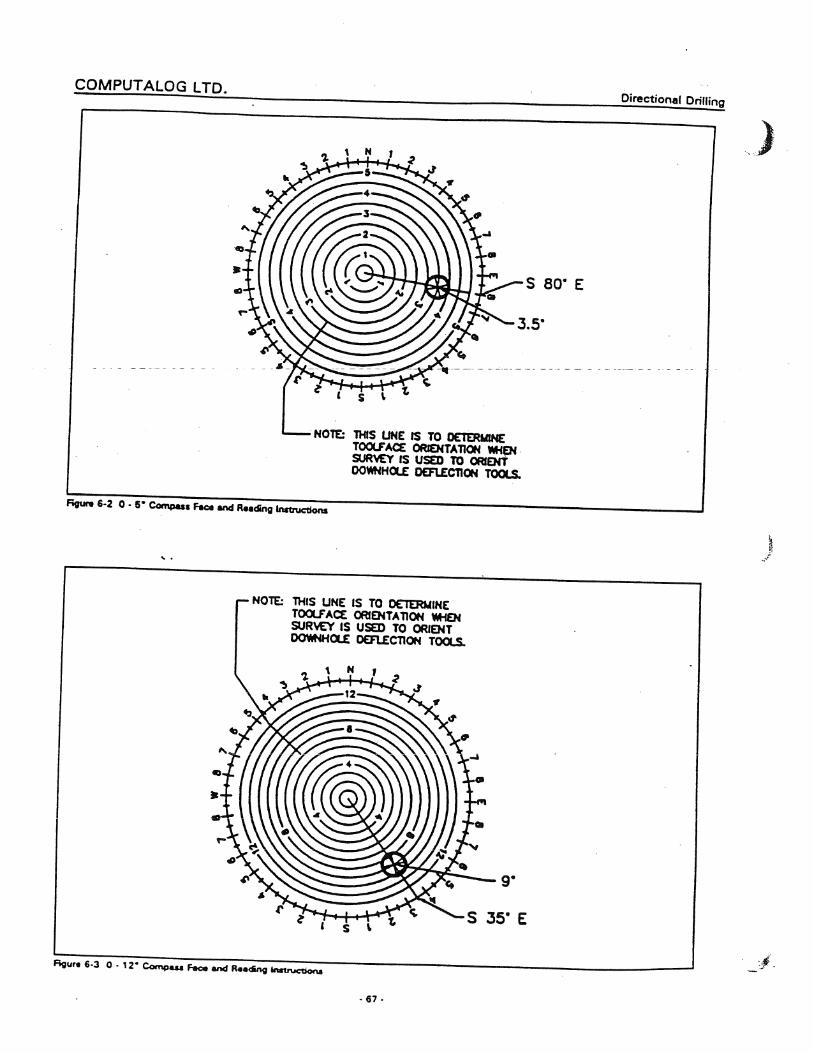


Quick Start Guide Contents - i
Quick Start Guide
FIRST
V4.00
Prepared For: Computalog Drilling Services Ltd.
By: Pangaea Systems Inc.

Quick Start Guide Contents - ii
Contents
Overview 5
About First............................................................................................................5
Getting Started 6 Quick View ...........................................................................................................6
Using FIRST 7 Creating A New Job..............................................................................................7
Entering Data 8
General Tab .........................................................................................................8 Contents..................................................................................................................................... 8 Wellsite Info / Personnel.......................................................................................................... 8 Wellsite Info / Personnel cont’d……….................................................................................. 9 Surface Info/ Wellbore Sections............................................................................................. 9 Hole Planning / Planned Targets .........................................................................................10 General Notes .........................................................................................................................10
Rig Data Section................................................................................................. 10 Contents...................................................................................................................................10 Rig Tools Inventory................................................................................................................11 Rig Bits .....................................................................................................................................11 Rig Pumps ...............................................................................................................................12
Inventory Section ................................................................................................ 12 Contents...................................................................................................................................12 Directional Tools .....................................................................................................................13 MWD Tools..............................................................................................................................13 Motors ......................................................................................................................................14 Other Inventory.......................................................................................................................14 Inventory Notes.......................................................................................................................14
BHA Section....................................................................................................... 15 Contents...................................................................................................................................15 BHA Information – Part 1 ......................................................................................................15 BHA Information – Part 1 cont’d………..............................................................................16 BHA Information – Part 2 ......................................................................................................16
Daily Section ...................................................................................................... 17 Contents...................................................................................................................................17 Daily Information – Part 1......................................................................................................17 Daily Information – Part 1 cont’d…….. ...............................................................................18 Daily Information – Part 2......................................................................................................18 Daily Information – Part 3......................................................................................................19
Costs Section ..................................................................................................... 20 Contents...................................................................................................................................20 Segment Costs Detail............................................................................................................20
Logs Section ...................................................................................................... 22 Contents...................................................................................................................................22 Additional Job Charges .........................................................................................................22 Usage Control.........................................................................................................................23 Incidents Log...........................................................................................................................24 Tool Transfer Log...................................................................................................................24 Tool Transfer Log Cont’d………..........................................................................................25

Quick Start Guide Contents - iii
Surveys Log ............................................................................................................................25 Menus ................................................................................................................ 26
File............................................................................................................................................26 File – Import ............................................................................................................................26 File – Import cont’d………..................................................Error! Bookmark not defined. File – Export ............................................................................................................................28 Edit............................................................................................................................................28 Section.....................................................................................................................................28 Page.........................................................................................................................................28 Reports.....................................................................................................................................28 Tools .........................................................................................................................................28 View..........................................................................................................................................29 Help..........................................................................................................................................29
Navigational Bar ................................................................................................. 30 Reports .............................................................................................................. 31
Inventory List...........................................................................................................................31 Detailed BHA...........................................................................................................................31 Doghouse BHA.......................................................................................................................31 Slide Sheet..............................................................................................................................31 Motor Evaluation.....................................................................................................................31 Daily Activity............................................................................................................................31 Daily Costs ..............................................................................................................................31 Job Costs Sheet.....................................................................................................................31 Cost Summary........................................................................................................................32 Usage Control.........................................................................................................................32 Tool Transfer Ticket...............................................................................................................32 Consolidated Tool Transfer..................................................................................................32 Incident Report........................................................................................................................32 Terms & Conditions................................................................................................................32 BHA Worksheet......................................................................................................................32 Slides Worksheet....................................................................................................................32
Lookup Lists....................................................................................................... 33
Glossary of Terms 37


Quick Start Guide Overview - 5
Overview
About First The Field Reporting System (FIRST ) is an application to track and maintain data collected at drilling rig sites. FIRST allows you to store, maintain and retrieve information about drilling jobs without the need for repetitive, time consuming paperwork when you are in the field.
In addition to saving time by entering data only once, FIRST allows you to retrieve and re-use previously entered data, transfer drill site info and reports, and offers safer storage of crucial information. All this can be done quickly and easily.
FIRST was designed with you in mind. Resembling a typical notebook or daytimer, using the application will seem familiar even if it’s your first time.

Quick Start Guide Getting Started - 6
Getting Started
Quick View FIRST’s tabbed sections make it easy to record rig site information. Within each section there is a contents or selection page, followed by the pages of recorded information. Simply point your mouse to an item and left click to quickly access a different section or page. (See Glossary for additional Tab Information)
Logs Tab
Rig Data Tab
General Tab
Inventory Tab
BHA Tab
Daily Tab
Job Costs Tab
Reports Palette
Navigational Bar
Tool Bar
Main Menu Bar

Quick Start Guide Using FIRST - 7
Using FIRST
Creating A New Job Creating a new jobfile is a simple process. Just follow these instructions:
? Double Click on the FIRST icon that appears on your desktop. (FIRST will open to the last jobfile used as a default.)
? Using your mouse, go to the Main Menu Bar, Click on File ->New. A New Job File window will open. Defaults for the Job Number, Start Date and End Date are already entered.
? Enter the File No. (2 optional alpha characters – base code – followed by 4 or 5 digits) and the start date of the job. Enter a date for the end of the job. This can be changed throughout the course of the job, so that the last day of the job is the final date in the paperwork. Click OK.
? FIRST will prepare the files and database ready for you to enter the job data.
? Ensure units are consistent with the country you are in. If you need to change, go to Tools -> Job Options on the main menu bar.

Quick Start Guide Entering Data - 8
Entering Data
General Tab Contents
The first page in the General Tab lists the contents of the general section. When your mouse is moved over a selection, the selection highlights. When your selection is highlighted, simply left click to jump to your selection. You can also quickly turn to the next page by clicking the mouse on the Page Turn symbol at the bottom corners.
Wellsite Info / Personnel The Job File No., Job Start/End dates that you entered on the Create New Job File screen will appear on the General – Wellsite Info page. As you move your mouse around the page, editable fields will be outlined with a red box. Down Arrows and the Magnifying Glass indicate a drop down list allowing you to select an entry for the field.
If an appropriate selection does not exist, edit the box to reflect the appropriate data.
Fill in the Wellsite information sections for File Numbers, Well Info and Rig with the information provided to you by the company.
Page Turn Symbol

Quick Start Guide Entering Data - 9
Wellsite Info / Personnel cont’d………. Page G – 3 is used to set up a contacts list. Using the drop down lists, select the Company Name (default is Computalog Drilling Services Ltd.), and then select the correct Phone and Fax numbers. Type in the Sales Rep name from the information provided to you.
To add a new person to the Personnel List, click on the + sign. In the Personnel Info, “New Contact” will appear. The Personnel Info can be edited with the person’s correct information. Ensure that all required information on the Company Man, Directional Supervisor and MWD Supervisor is entered. It is suggested that you include any other personnel that you have contact with as well. A drop down list with job descriptions is provided for easy entry (Please do not change the spelling of the descriptions). Once a person is entered, he can be deleted using the – symbol. It is possible to browse through the personnel detail records by clicking on each Person in the Personnel List with the mouse or by clicking a Person and then using the computer keyboard up and down arrows.
Note the order the personnel appear in the Personnel list determines the order in which they are printed in the reports. This ordering can be changed by selecting a person and using the up and down arrows appearing at the bottom of the Personnel List.
Surface Info/ Wellbore Sections Fill in all geographical and geomagnetic information on page G-4. When data must
be entered in a specific manner, hints are provided in italics or light blue letters.
Selection information in the drop-down boxes can be edited if no appropriate selections are offered.
AFE, PO, WO number spaces are provided. Not all jobs will have a number for each of these spaces, but all jobs will have at least one of them. This can be obtained from the onsite Oil Company Representative.
To start filling in the required Wellbore section information, click on the + sign to add new section information. Again, where data must be entered in a specific manner, hints are provided in light blue or gray printing.

Quick Start Guide Entering Data - 10
Hole Planning / Planned Targets
Fill in the Planned Well Details and Survey Details on page G-6 by following the hints provided in light gray text. Some fields also have drop down lists to choose from.
To enter Target Info (Planned), click on the + sign to add new targets. After entering Target Info will appear in the Target List (Planned) at the top of page G – 7. Remember to enter the information in the format shown by the light gray hint text.
General Notes Use this section for any relevant job site details, changes etc. daily. This will print on the “Job Overview” report.
There should be a brief summary entered every day in this report.
Rig Data Section Contents
The first page in the Rig Data Tab lists the contents of the section. When your mouse is moved over a selection, the selection highlights. When your selection is highlighted, simply left click to jump to your selection. You can also quickly turn to the next page by using the Page Turn symbol at the bottom corner.
Page Turn Symbol

Quick Start Guide Entering Data - 11
Rig Tools Inventory
Use this section to add all rig tools (tools supplied by drilling contractor or Oil Company) that will be used on the job. Simply click on the + sign to add a tool. This will activate the fields on the page R – 3. Light gray text will indicate how to enter required fields. Make sure you enter all tools as they are included in BHA’s. Once you have entered the rig tools, the information will be available in lookup lists in other sections of FIRST . Once an inventory item is used in a BHA, you cannot delete it from the inventory until you have removed it from the BHA. You may however modify the data fields for the item – the item will still be connected to the BHA.
In the Component field you can select a component from the items in the drop down list or type one in if an item doesn’t appear in the list. It is recommended to use the selection supplied whenever possible. This will standardize the data, allowing effective database searches when your job file is merged with the central database.
Note the length field is just an average length – when rig tools are added to the BHA later, the total length of a group of drill pipe for example must be manually entered.
Rig Bits
Pages R – 4 and R – 5 allow you to add bits to the rig bit list. Click on the + sign to add bits. Include the serial number to make it easier to identify the bit later. Bit information will be referenced by the BHA and Daily reports.

Quick Start Guide Entering Data - 12
Rig Pumps
Click on the + sign to add rig pumps to the rig pump list. It is important to fill in the stroke length so the flow rate can be calculated in the Daily Section. The order that the pumps appear in the list will be the same order that is used on the Daily page where the flow rates are calculated.
Pump efficiency will alter the flow rate calculated by the program.
Inventory Section Contents
The first page in the Inventory Section Tab lists the contents of the section. When your mouse is moved over a selection, the selection highlights. Simply left click on the highlighted selection to jump to your selection. You can also quickly turn to the next page by using the Page Turn symbol at the bottom corner.
Page Turn Symbol

Quick Start Guide Entering Data - 13
Directional Tools
Directional inventory is added to the Directional Tools list. Fill in all details that apply, including length, as it is used in BHA length calculations. This includes all tubulars that may need to be tracked in a BHA
Leave Product Code blank unless you have the code used by your office for each item.
Original Field Date is the date the item was shipped to a job from the base.
Job Receive Date is the date the item was shipped to location or the day the job started. If on a multi-well project, the original Field Date should stay the same for all wells until the tool is shipped elsewhere or the project ends. The Job Receive Date should reflect the start date of the current well, or the date the item was shipped to the current well.
Job Depart Date is the date the tool was transferred from location to base or another job – this field is read-only on this form since it is set to the Transfer Ticket Date in the LOGS – Tool Transfer.
**NOTE – Include MWD tubulars if they are part of the BHA items and are to be tracked automatically in the usage chart.
MWD Tools
Click on the + sign to add MWD inventory to the MWD Tools list. Only include tools that are not tracked in the BHA components list (i.e. non-tubular MWD tools). MWD Tools in this list are manually tracked in the usage grid. (Batteries). Not all fields may apply here.

Quick Start Guide Entering Data - 14
Motors
Click on the + sign to add Motors inventory to the Motors list. Motor information is referenced by the BHA and Daily reports.
Other Inventory
Click on the + sign to add items to the list that do not fit into other categories. Use the drop-down lists as much as possible.
Inventory Notes
Use this page to record notes regarding inventory issues. For example, you may note that certain tools were sent to another job site, lost or damaged items. The notes will print out on the inventory report.

Quick Start Guide Entering Data - 15
BHA Section Contents
BHA Section Contents lists the BHAs. Add a BHA by using the + sign. You may also right click your mouse and select Add BHA from the menu or by pressing the Insert button on your keyboard while your cursor is in the list. Delete a BHA by selecting a BHA and then using the – sign, or pressing the Delete key on your keyboard. If the BHA is referenced in the Daily Activities section, you will not be able to delete it until all references to it have been removed from the Daily Activities section.
Navigating to listed BHAs is simple. You can use the arrows to move up and down in the list. When you have made your selection either double left click your mouse key, press the Go to BHA symbol or use the Page Turn symbol to move page by page.
BHA Information – Part 1
Use the left side of the page to add Components from the inventories into the BHA. Click the + sign to open the Edit Component screen. To open a larger selection screen, simply click the ZOOM symbol. Pressing the Clone symbol will allow you to copy the Components list from another BHA in the job into the current BHA.
Note – when cloning, the current BHA component list will be completely overwritten with the cloned BHA component list. Once the component list has been cloned it is possible to make additions or changes in the current BHA component list.
Move Up or Down in List
Add or Delete BHA
Page Turn Symbol
Go to BHA Symbol
Change BHA Name
ZOOM symbol
Refresh symbol
Edit Component
Clone symbol

Quick Start Guide Entering Data - 16
BHA Information – Part 1 cont’d……….
Select a Source from the list box selections, then select a component from the Component list box and click OK.
Enter your bit usage and motor usage information on the right-hand page. Motor comments will appear on the motor evaluation report along with other automatically gathered information. You may enter up to 4 bit nozzle sizes. Flow areas for the nozzles and total combined flow area will be automatically calculated. If there are more than 4 nozzles or there are no actual nozzles on the bit, a manually entered TFA can be used. If this is the case, make sure that the other nozzle diameters are set to 0. Also ensure that the manual TFA data field is 0 if the data fields for individual nozzles are used.
BHA Information – Part 2
Enter BHA parameters on the left-hand page. Start/end dates and depths are automatically obtained from the Daily Activities entries, where depths and BHA numbers are assigned to each activity. Angle in and angle out values are pulled from the slide sheet record.
On the right page, add slide sheet information to the list box. You can add slide records by using the + sign, or you can open a zoom window with the Zoom button. You only need to enter your single length, bit depth, and slide meters; the rest will be calculated. If you enter a single length of 0.0, then you can enter a non-contiguous bit depth (i.e. it does not continue directly from where the previous record finished rotating). Otherwise, when the numbers recalculate, the bit depths are adjusted to be equal to the last ‘rotate to’ depth plus the single length
Zoom Screen
Edit Component Screen

Quick Start Guide Entering Data - 17
Daily Section Contents
The calendar on this page shows the dates for the job in green. Double-click on a date to jump to the relevant page, or use the Go to Date button. The date range for the job can be changed by selecting the desired date and then using the Set Job Start/Set Job End buttons or using the menu items in the right-click menu. When this is done, it will change the start/end days in the general section as well, but will not change the cost segment dates.
Daily Information – Part 1
Add daily activities on the left-hand page. You may use the + sign for the Edit Activity Item or the Zoom (Daily Activities List) screen shown below, for this task.
Set Job Start/Set Job End buttons
Zoom Screen
Edit Activity Item Screen

Quick Start Guide Entering Data - 18
Daily Information – Part 1 cont’d…….. For the first day of the job, there is a data field for the starting depth (Depth In On First Day) at the top of the page. The Work Status drop-down determines an Operating or Standby day. This field must be filled in for proper meterage calculations. Double-clicking on a list item, or using the Edit button or the Edit menu item on the right-click menu can edit activity items. Adding and deleting follows the standard methods. For more detail in adding activities, use the Zoom button or the Zoom right-click menu item. This opens a large window with pre-defined activity codes on the left and an enlarged view of the activities list box on the right. Working in this screen is very similar to working in the BHA zoom screen.
Activities are categorized into Circulating, Drilling, MWD, Tripping, Rig and Other. Use the activities that are provided. You cannot add new activities to the lists. The existing activities are coded as to the type of hours associated with the activity (i.e. motor drilling hours, rotary drilling hours etc.). Each activity can only be associated with one type of hours, so split up combined periods from the tour sheets into separate activities.
Make sure you include the correct BHA number and depth in each activity. Meterage for the day and for each BHA is calculated from the depths entered. When starting a sidetrack, enter the depth for the sidetrack and click the box ‘set new start depth’ in the bottom left corner of the Edit Activity Item box. This will ensure the proper meterage calculations for the sidetrack. The total meterage for the day will show the sum of the meters made before the sidetrack and since the sidetrack. Do not leave a depth blank; it will be interpreted as a zero depth and throw off calculations. Also, do not leave the BHA number blank during a series of entries. It can only be blank between BHAs and ensure the BHA numbers are contiguous (no gaps and do not alternate i.e. 1,2,1,1). This will cause unpredictable results in the calculated hours and meterage.
Fill in other daily parameters on the right-hand side.
Daily Information – Part 2
On the left page, enter the daily mud information.
Liquid Type/Rate, Gas Type/Rate are for UBD applications only and can be left blank when this does not apply.
On the right page, flow rates and pressures are recorded. You can enter the SPM and liner size for up to three pumps. The order of the pumps is the order that is shown in the list box on the Rig Pumps page. The flow rates will be calculated automatically.

Quick Start Guide Entering Data - 19
Daily Information – Part 3
Add daily Personnel On Site on the left-hand page. You may use the + sign for the Edit Personnel On Site , the Zoom (Personnel On Site List) screen shown below, or the Clone for this task. Clone allows you to copy the Personnel On Site List from another day in the job to the currently selected day. Cloning the personnel list from another day with the same list is a short cut method of entering the personnel list. Once the list has been cloned it may be edited for any additions or changes.
Note – when cloning, the current Personnel On Site list will be completely overwritten with the cloned daily personnel list. It is recommended therefore, clone the desired daily personnel list before making any changes.
When adding personnel to the current day using either the Zoom or the Edit Personnel On Site you will be required to specify the personnel Work Type (Field, Standby, Training or Travel). This designation is independent of the daily Work Status in Daily Information – Part 1.
Enter any comments on the right page, they will appear in the Daily Activities report.
New Page Personnel On Site
Zoom symbol Clone symbol
Zoom Screen Edit Personnel On Site Screen

Quick Start Guide Entering Data - 20
Costs Section Contents
The Contents page list of Job Cost Segments. Using the + sign allows you to add a new segment, the – sign is used to delete, clicking on the Go symbol will take you to the highlighted segment. It is possible to change the name of an existing segment with Change Segment Name activity.
Segment Costs Detail
The Costs in this Segment page (page C-2) allows you to move up and down, add, delete, edit, refresh and clone segment. Clicking on the plus sign or the Zoom symbol will bring up the Segment Costs List allowing you to select the itemized costs for the segment.
Change Segment Name

Quick Start Guide Entering Data - 21
On the Segment Costs List screen, the tabs at the bottom left of the screen allow you to pick cost
items from different areas of FIRST – Price Book, Inventory Items and Additional Charges (see Logs Section – Additional Job Charges for entering items that will appear in this Additional Charges list).
If you need to change the unit price of a selected item (i.e. if you need to charge for motor hours), from the Segment Costs List screen double click on the item or from the Costs in this Segment list double click the item or select the item and press the Edit Item symbol to edit the cost. Select the Override Price and UOM for this item and enter the cost.
The Segment Costs page (page C-3) shows the segment costs by day. This is a small grid showing the quantities for each cost item for each day, along with daily cost totals and job totals for each cost item. Double-clicking in the grid on a cell or pressing the Edit Amount symbol while a cell is selected will put the cell into edit mode so that you can change the quantity charged for the selected item for that day. The quantities for inventory items are not automatically calculated, in case there are special arrangements regarding the billing for the items so, make sure that you set the quantities for each inventory item that is charged, for each day as required. Pressing the Zoom symbol on this page will bring up a larger version of the Segment Costs grid.
Editing the quantities on this screen are the same as on the smaller Segment Costs grid page.
Segment Costs List Screen
Segment Costs Zoom Screen
Edit Amount symbol

Quick Start Guide Entering Data - 22
Logs Section Contents
The first page in the Logs Section Tab lists the contents of the section. When your mouse is moved over a selection, the selection highlights. Simply left click on the highlighted selection to jump to your selection. You can also quickly turn to the next page by using the Page Turn symbol at the bottom corner.
Additional Job Charges
Items not appearing in the Inventory or the Price Book but are charged to the job will be entered here. These items will show up on the Additional Charges tab of the Segment Costs List edit screen. Press the + sign to add an item. Use the Product Code 999999 for items that do not have an assigned code.
Page Turn Symbol

Quick Start Guide Entering Data - 23
Usage Control
The Usage Items list on the right-hand page shows all the personnel and inventory items on the job, followed by the total days that each is used over the length of the job – if they are not used the Days will total 0 (zero). If the list is not ordered the way you like, it can be reordered using the up and down arrows to move or the mouse to drag and drop individual items up and down in the list. Pressing the Sort symbol will sort the entire list so the alphabetized personnel appear at the top and the alphabetized inventory appears at the bottom. Sorting items in the Usage Items list affects the ordering in the Usage Control grid.
The Usage Control grid on the left-hand page shows the specific days that each item in the Usage Items list is used on the job. Cells with a 1 indicate the item was used on the job for that day. For most of the items appearing in this grid, the usage is determined automatically by FIRST based on the entries in Daily – Personnel list and the BHA – Components list(s). The usage for inventory items such as Lift Subs, Pickup Subs, Survey Kits, Single/Multi-shot survey tools, Tool Baskets and MWD tools, items that do not make up part of the external BHA components, cannot be automatically determined. The descriptions for these items are presented in blue, indicating the usage for that item can be toggled off and on manually. To toggle these items for a specific day double-click the appropriate cell or select the cell and then press the Toggle Value symbol. Pressing the Zoom symbol on this page will bring up a larger version of the Usage Control grid.
In the Usage Control zoom screen it is possible to toggle the ‘adjustable’ cells by double-clicking on the appropriate cell.
Sort symbol Toggle Value symbol
Usage Control Zoom Screen

Quick Start Guide Entering Data - 24
Incidents Log
Incidents or problems that arise on the job are entered here. Press the + sign at the bottom of the Incidents list to add an item. It is important to complete as much of the Incident Details information and summaries as possible.
Tool Transfer Log
Tools that are transferred from the current job to another job or back to the base are entered here.
Tool Transfer Tickets are created on the left-hand page. You may use the + sign at the bottom of the Transfer Tickets list to create new tickets. The ticket number is generated automatically, but it is possible to either specify a different number when the ticket is created or after ticket creation by pressing the Change Ticket Number symbol. The Destination Details, Shipping Details and Transfer Comments (if any) make up the cover information for the Transfer Ticket, therefore tools on a Ticket may only go to one destination. Note – the ticket transfer date that is specified here is the date will appear in Job Depart Date field for all inventory items included on the ticket. Transfer Tickets for tools returning to the base should be specified by selecting ‘RETURN TO BASE’ from the Well Name drop-down list. For Tickets going to other jobs the Well Name selection information in the drop-down box can be edited to allow entry the appropriate information.
Change Ticket Number symbol
New Page Tool Transfer Log

Quick Start Guide Entering Data - 25
Tool Transfer Log Cont’d………. On the left-hand page, you may use the + sign for the Edit Transfer Item, or the Zoom (Transfer Items List) shown below, to add Transfer Items, tools, to the ticket. Use the – sign to remove tools from a ticket. Note - removing a tool item from a ticket also clears its inventory Job Depart Date .
FIRST does not allow a tool to be transferred on two tickets. In the Transfer Items List zoom
screen, items appearing in the Inventory Selections list on the left with a gray background are items that already appear on a transfer ticket. The Edit Transfer Items screen does not display items that have already been transferred.
Surveys Log This section is not currently available.
Transfer Items List Zoom Screen Edit Transfer
Items Screen

Quick Start Guide Entering Data - 26
Menus File
This sub menu allows you to perform FIRST job related actions. It includes New, Open, Save, Save a Copy to Floppy Disk, Import, Export, and Exit. By default FIRST will save and open job files in the c:\first4\jobfiles directory. Job files will have a JOB file extension.
The explanation of New is covered in Using FIRST – Creating a New Job above. Aside from Import and Export (explained below), the other menu items are self-explanatory.
File – Import The import FIRST Job File… menu item allows you to import job data from another job file. Importing information from another Job file can greatly reduce the amount of import required to start a new job. Importing from another job file is intended for use with newly created job files only, as previously existing data in several areas are replaced and in some it is discarded. Data is replaced in:
General Section: Client, Field, Prov/State, Country, Rig Name, Rig Number, Service Co., Service Type and all Personnel records
Rig Section: Tools, Bits, Pumps
Inventory: DIR Tools, MWD Tools, Motors, Other Tools
Segments: Segments, Segment Costs, but not daily charges
Logs: Additional Job Charges
All the data above is replaced even though you may not choose any inventory items to import. Data is discarded in:
BHA: BHAs, BHA Components, BHA Slides
Daily: BHA field in Daily Activity lines
When you use the import FIRST Job File… to open a job file the Select Inventory Items to Carry Forward From Previous Job screen is displayed. Select the tools you want to import by checking

Quick Start Guide Entering Data - 27
the box beside each item, either individually or with the Select All button. All the imported items will have the inventory Job Receive Date set to the Receive Date entered on this screen.
By default the current date will be used as the Receive Date however it is adjustable to any date on or between the Job Start Date and Job End Date. The Carry Forward Original Field Dates? flag, allows you to carry forward the Original Field Date for all imported inventory items.
The import Lookups Data File… menu item allows you to import other Lookups Data files that may have been updated with other information, replacing your current lookups data. Lookups Data files are by default saved with a LKP file extension. It is recommended that you export your current lookups data prior to importing new lookups data.
Using the import Tool Transfer File… menu item, it is possible to import the inventory tools sent from the Dispatch System and therefore reduce the amount of typing to enter the inventory used on the job. When the Transfer File, created with a TTR file extension, is opened, the Select Tools to Import from Dispatch Ticket screen will be displayed. This lists all the tools available for import in
the transfer file. Select the tools you want to import by checking the box beside each item, either individually or with the Select All button. It is possible to change the tool Type for each item prior to importing, so check that each type is correct. All the imported items will have the inventory Job Receive Date and Original Field Date set to the Receive Date entered on this screen. By default the current date will be used as the Receive Date however it is adjustable to any date on or between the Job Start Date and Job End Date. After the tools have been imported go through all the imported items in the Inventory screens and complete any of the fields missing relevant data.

Quick Start Guide Entering Data - 28
File – Export As you begin to add and adjust items in the various lookup fields, these changes are saved in the FIRST database. It is possible to export this Lookup Data so that this revised list can be used on other computers running FIRST. By default, the exported file will have a LKP file extension.
Edit This menu item provides the standard edit functions such as Cut, Copy, Paste, and Select All.
Section In addition to the Section tabs and the Navigational Bar already provided in FIRST, this sub menu provides the menu items as well as hot keys for navigating to the different parts of the FIRST application.
Page This sub menu provides page-level movement through FIRST. History Back and History Forward to allow you to move back to where you were. First and Last provide the ability to move quickly to the first and last pages of the current section. Next and Prior allow you to move to the next and previous pages including from section to section.
Reports This sub menu provides the menu items plus hot key short cuts for printing the various reports.
Tools This sub menu provides a number of tools helpful and necessary for the proper functioning of FIRST .
The Spell Check facility is available for all Notes, Comments and text items. Note – it is available through the F7 short cut key.
The Job Options… item allows you to specify the currency type and measurement units to be used for operating FIRST.
If the need arises, Change Job File Name… allows you to change the file name of the existing job

Quick Start Guide Entering Data - 29
– it is possible to change the File Number as well as the Date Code. Changing the Date Code here will not change the Job Start Date.
The Rebuild Data Files and Data Viewer options are intended for usage only if you are experiencing major data problems with FIRST and even then it is recommended that these items only be used on the advice of the Systems Administrator.
The Calculator displays the calculator available from the Windows® operating systems.
View This sub menu allows you to adjust which FIRST features are displayed. You can toggle off and on the various menu bars; Tool Bar, Navigational Bar, and the Reports Palette. The 640 x 800 Mode , which was included for computers with lower resolutions, toggles off the Tool Bar, Navigational Bar and the Reports Palette and makes the Tool Bar into a ‘floating menu’ so as to conserve display space.
Help As well as providing some of the standard items that you would find under help, this sub menu also includes an Expiry Date… item.
The Expiry Date feature allows you to see what the FIRST current expiry date is and can also be used to extend the license period. It is necessary to phone the Systems Administrator for the valid code that can be entered in the input box provided.

Quick Start Guide Entering Data - 30
Navigational Bar The Navigational Bar appearing along the left side of FIRST provides quick access to the various sections and pages of the application. Clicking on the ‘Section Bars’ will open up a menu with icons for the various activities in each section. The icons on the BHA menu represent 2 pages and on Daily 3 pages. In addition to using the Page Turn symbols to go to these respective pages in BHA and Daily, it is possible to traverse through the pages represented by these icons by either clicking on the icon again or by right-clicking the mouse on the icon and selecting the desired page from the
menu.
Right -click menu on Daily
Navigational Bar
Page Turn symbol

Quick Start Guide Entering Data - 31
Reports There are a few ways to access reports for FIRST . You can use the Reports menu and select a menu item to print a particular report. You can use the Quick Print button on the toolbar if it makes sense for the current page (i.e. current inventory section, current BHA, current day). You can also use the report palette at the bottom of the main window.
For most reports, you will be presented with a selection dialog box that will allow you to choose, for example, which inventory sections, or which BHAs, or which days to print. Then, a report preview is shown. You can cancel the printouts at this point, or click the print button on the toolbar to print the report.
Inventory List This report can show each inventory section (Directional Tools, MWD Tools, Motors, Other Tools) individually or combined together.
Detailed BHA The detailed BHA report includes the components list, motor info, bit info, and daily info for selected BHAs.
Doghouse BHA The doghouse BHA report is a list of the BHA components, printed in a landscape orientation. No other information is displayed. It is meant for use as a reference in the doghouse.
Slide Sheet This report shows the slide sheet information for selected BHAs.
Motor Evaluation This report shows the motor usage comments for selected BHAs along with relevant BHA, motor, bit, and daily information combined automatically by the program.
Daily Activity The Daily Activity report shows all daily information, including activities list, hours breakdown, BHAs used information, mud, pressures, flow rates, and daily comments. There is a sign-off spot for the customer.
Daily Costs This report lists out the cost items for the job, with the quantities and costs for the selected days. There is a sign-off spot for the customer.
Job Costs Sheet This report shows all cost items and job days in a grid format with totals. There is a sign-off spot for the customer.
Quick Start Guide Entering Data - 32
Cost Summary This report lists out the cost items for the job, with the quantities and costs for the entire job or for specific segments. There is a sign-off spot for the customer.
Usage Control The usage control report shows all inventory items and job days in a grid format with totals.
Tool Transfer Ticket This report shows the shipping information and the tools being transferred.
Consolidated Tool Transfer This report shows a consolidated list of the selected Tool Transfer Tickets on which tools were transferred from the job including general tool information and the destination for each item.
Incident Report This report shows a report for each selected incident.
Terms & Conditions This report shows the general Terms & Conditions under which services, personnel, equipment etc. are provided.
BHA Worksheet A blank spreadsheet for recording BHA components.
Slides Worksheet A blank spreadsheet for recording slides information.

Quick Start Guide Entering Data - 33
Lookup Lists There are two type of lookup lists – ones that you can edit (add, delete, modify), and ones where the choices are fixed. The lookups that can be edited allow you to add your own items to save on typing when you need to use that item again later. The non-editable lists are restricted from user editing in order to preserve their exact contents. The items in these lists will be used as key values in database searches when the job files are combined into the main database.
The activity lists are shown below for reference.
Activity Lookup List – Circulating - Blow Down Hole With N2 - Circ & Accumulate Surveys - Circ & Condition Hole - Circ & Condition Mud - Circ & W.O.O. - Circ Bottoms Up - Circ Sample - Circulating - Circulating - See Comments - Displace Hole - Displace Hole With N2 - Flow Test - Pump Down Survey Barrel - Pump Out Singles - Unplug Nozzles - Unplug Tools - Work Stuck Pipe & Circ - Work Tight Hole & Circ
Activity Lookup List – Drilling - Back Ream - Build Trough - Control Drill - Drill Mouse Hole - Drill Out Flt, Shoe & Cmnt - Motor Drill To KOP - Orienting With Motor - Polish Cement Plug - Ream - See Comments - Ream Hole - Rotary Drill - Rotary Drill To KOP - Rotating With Motor - Time Drill

Quick Start Guide Entering Data - 34
Activity Lookup List - MWD - Change Batteries - Change MWD - Change Pulser - EM MWD Surveys - Gamma Rerun - Gyro Wellbore - Shallow Pulse Check - Shallow Test Tools - Wait On MWD Tools - Work On EM MWD - Work On MWD
Activity List – Other - Cement Casing - Coring - DST - Fishing - Logging - Make Up Fish Tools - Mill Window - Move Rig - MU Whipstock - Other - See Comments - Recover Core BBL - Released - Run Casing - Run Liner - Set Bridge Plug - Set Cement Plug - Standby - Travel Home - Travel To Job - Undefined - See Comments - W/L Surveys & Orienting - Wait On Cement - Wait On Cementers - Wait On Daylight - Wait On Directional - Wait On Directional Tools - Wait On Fisherman - Wait On Loggers - Wait On Mobilization - Wait On Orders - Wait On Other Tools - Wait On Weather
Activity List – Rig - BOP Drill - Change Pump Liners - Fire Up Boiler - Flow Check - Lay Down Derrick

Quick Start Guide Entering Data - 35
- Move In Rotary Tools - Nipple Up BOPs - Pressure Test - Rig Out Rotary Tools - Rig Repair - Rig Service - Rig Up
Activity Lookup List – Rig cont’d - Rig Up Cementers - Rig Up Derrick - Rig Up RBOPs - Rig Up Rotary Tools - Rig Up Top Drive - Rig Up UBD Equipment - Safety Meeting - Slip And Cut - Spot Shacks - Tear Out Rig - Tear Out Top Drive - Weld On Conductor - Wireline Survey - Work on Pumps - Work on Top Drive
Activity List - Trip - Change Bit - Change Bit And Motor - Change Motor - Change Out Drill Collars - Change Out Drill Pipe - Handle Directional Tools - Lay Down Directional Tools - Lay Down Drill Collars - Lay Down Drill Pipe - Lay Down HW Drill Pipe - Pick Up Drill Collars - Pick Up Drill Pipe - Pick Up HW Drill Pipe - Pipe Swap - POOH - See Comments - POOH For Bit - POOH For Directional - POOH For EM MWD - POOH For Motor - POOH For MWD - POOH To Change BHA - POOH To Change Mtr Set - POOH To Check For Wash - POOH To Check Tools - POOH To Log - POOH To Recover Surv Barrel - POOH To Run Casing - POOH With Fishing Tools

Quick Start Guide Entering Data - 36
POOH With Gyro - POOH With Reamer - POOH With Whipstock - POOH, Lay Down DC - POOH, Lay Down DP - POOH, Lay Down HWDP - PU Directional Tools - Pull Back For Sidetrack - RIH - RIH - See Comments - RIH Open Ended - RIH With Directional - RIH With Fishing Tools - RIH With Gyro - RIH With New BHA - RIH With New Bit
Activity Lookup List – Trip cont’d - RIH With Overshot - RIH With Rotary Tools - RIH With Whipstock - Snub Out - Strip In - Survey On Trip In - Trip In - Trip Out For DST - Trip Out Sideways - Trip Out With DST - Trip To Set Up Motor - Trip To Turn Down Motor - Wiper Trip - Work Stuck Pipe - Work Tight Hole

Quick Start Guide Glossary of Terms - 37
Glossary of Terms
Reports Palette: Allows quick, easy access to all available reports.
Navigational Bar: The Navigational Bar allows quick access to other sections and their contents.
Tool Bar: Allows you to create NEW job, OPEN existing job, SAVE job, SAVE job TO FLOPPY, PRINT, GO BACK, GO NEXT, QUICK PRINT and EXIT application
Logs Tab: Record Addition Job Charges, Usage Items/Usage Control, Incidents Logs, Tool Transfer Logs, Survey Logs in this section.
Job Costs Tab: Record Build and Segment costs (Item, Serial #'s, Unit Of Measure, Price on the Left side of the page. Daily recap of costs appears on the Right side of the page.
Daily Tab: Allows you to record/edit job start and end dates, record daily activities, hours, depths, parameters, WOB, and Daily Progress Summary.
BHA Tab: Contains information on Build Hole Assemblies
Inventory Tab: Contains Directional Tools, MWD Tools, Motors, Survey Tools/Other Items Inventories and Inventory Notes.
Rig Data Tab: Contains Information on Rig Tools Inventory, Rig Bits Inventory and Rig Pumps
General Tab: Contains Wellsite Info/Personnel, Surface Info/Wellbore Sections, Hole Planning/Planned Targets and General No


OppositeHyp
81) Sin 20 = Hyp
82) .3420 = Hyp
83) Hyp = 0.3420
4) Hyp = 23.3918
Opp1) Sin 20 = 23.3918
Opp2) .3420 = 23.3918
3) Opp =
4) Opp = 8.0000
81) Sin Q = 23.3918
2) Sin Q = 0.3420
3) Q = 19.998820
9 Possible Trig Scenarios
SOH Sin =
.3420 x 23.3918
First Scenario
Third Scenario
Rounded Off =
Second Scenario

AdjHyp
21.98111) Cos 20 = Hyp
21.98112) .9397 = Hyp
21.98113) Hyp = 0.9397
4) Hyp = 23.3916
Adj1) Cos 20 = 23.3916
Adj2) .9397 = 23.3916
3) Adj =
4) Adj = 21.9811
21.98111) Cos Q = 23.3918
2) Cos Q = 0.9397
3) Q = 20.0000
Third Scenario
Second Scenario
.9397 x 23.3916
9 Possible Trig Scenarios
CAH Cos =First Scenario

OppAdj
Opp1) Tan 20 = 21.9811
Opp2) .3640 = 21.9811
3) Opp =
4) Opp = 8.0011
8.00001) Tan 20 = Adj
8.00002) 0.364 Adj
3) Adj = 8.00000.364
4) Adj = 21.978
81) Tan Q = 21.9811
2) Tan Q = 0.3639
3) Q = 19.996420
9 Possible Trig Scenarios
TOA TOA =First Scenario
Third Scenario
21.9811 x .3640
Rounded Off =
Second Scenario

Trigonometria Basica Calculos Matematicos Basicos
This document is considered UNCONTROLLED and shall not be updated unless stamped with a green Controlled Copy stamp.
QF-GEN-F000? Call Rob for number. Rev. 2
L3-COM-CA-QF-GEN-F000?
Page 1 of 8
Comprendiendo la Trigonometria
Con conocimientos básicos, la trigonometría es fácil. Existen sólo 3 funciones de trigonometría. La parte complicada es poder identificar cuál función aplica. Hay tres números que se usan en cada función. Dos deben ya existir o ser conocidos y es un tercero el número que es calculado. Ésta es la base de la trigonometría. Las topicos siguientes cubren los elementos esenciales para aquéllos que tienen dificultades con la matemática.
Triangulo Basico Para poder usar una función de trigonometría, uno de los tres ángulos en el triángulo tiene que ser de 90 grados. Esta esquina de 90 grados se llama ángulo recto. Los tres lados en un triángulo de ángulo recto son el adyacente, el opuesto y la hipotenusa. El lado del triángulo más fácil de identificar es la hipotenusa. Es el lado más largo de un triángulo y siempre se denominará como hipotenusa. Los lados adyacentes y opuestos no son fijos. Sus nombres estarán relativos a que esquina del triángulo a la que están refiriéndose. El lado opuesto siempre es el contrario al ángulo que se está usando o se está intentando de encontrar o calcular (nunca el ángulo recto). El lado adyacente es el lado que queda o sobra lateral. Para claridad, hay dos diagramas debajo. Noten que cuando el ángulo de referencia cambia, los lados opuestos y adyacentes también cambian. Example # 1
Hipotenusa
Adyacente
Opuesto (Simpre es el lado mas largo del triangulo) (Siempre es el lado
opuesto al agulo que se trata de determinar o
calcular)
(el lado que sobra o queda)
a
El angulo que esta siendo calculado
Angulo recto del triangulo

Trigonometria Basica Calculos Matematicos Basicos
This document is considered UNCONTROLLED and shall not be updated unless stamped with a green Controlled Copy stamp.
QF-GEN-F000? Call Rob for number. Rev. 2
L3-COM-CA-QF-GEN-F000?
Page 2 of 8
Example # 2
Formulas Trigonométricas En trigonometria, hay sólo tres funciones básicas. Son el seno, el coseno y la tangente. Para simplicidad, se nombran normalmente como sen, cos y tan. Al usar una de estas tres funciones, la fórmula necesita un ángulo y un lado. El lado que se está tratando de determinar o calcular determinará cuál fórmula deberá usarse. Hay una frase que se usa para ayudar que recuerda las funciones arregladas. De una manera fonética, lea a lo siguiente como:
SOH CAH TOA Está da pie para:: Usando estas formulas, a continuación se muestra la resolución de las funciones trigométricas.
Hipotenusa Adyacente
Opuesto
(Simpre es el lado mas largo del triangulo)
(Siempre es el lado opuesto al agulo que se trata de determinar o calcular)
(el lado que sobra o queda)
a
El angulo que esta siendo calculado
Angulo recto del triangulo
Sen = Opuesto Hipotenusa Cos =
Adyacente Side Hipotenusa Tan =
Opuesto Adyacente

Trigonometria Basica Calculos Matematicos Basicos
This document is considered UNCONTROLLED and shall not be updated unless stamped with a green Controlled Copy stamp.
QF-GEN-F000? Call Rob for number. Rev. 2
L3-COM-CA-QF-GEN-F000?
Page 3 of 8
Ejemplo de Trigonometria Usando el Seno
64˚
A
74
Opuesto Hipotenusa
Sen =
A 74 Sin 64 =
.898794 = A 74
.898794 x 74 = A
A = 66.51

Trigonometria Basica Calculos Matematicos Basicos
This document is considered UNCONTROLLED and shall not be updated unless stamped with a green Controlled Copy stamp.
QF-GEN-F000? Call Rob for number. Rev. 2
L3-COM-CA-QF-GEN-F000?
Page 4 of 8
Ejemplo de Trigonometria Usando el Cosene
58˚
B 82
Adyacente Hipotenusa
Cos =
B 82 Cos 58 =
.529919 = B 82
.529919 x 82 = B
B = 43.45

Trigonometria Basica Calculos Matematicos Basicos
This document is considered UNCONTROLLED and shall not be updated unless stamped with a green Controlled Copy stamp.
QF-GEN-F000? Call Rob for number. Rev. 2
L3-COM-CA-QF-GEN-F000?
Page 5 of 8
Ejemplo de Trigonometria Usando la Tangente
51˚
26
A
Opuesto Adyacente
Tan =
A 26 Tan 51 =
1.234897 = A 26
1.234897 x 26 = A
A = 32.11

Trigonometria Basica Calculos Matematicos Basicos
This document is considered UNCONTROLLED and shall not be updated unless stamped with a green Controlled Copy stamp.
QF-GEN-F000? Call Rob for number. Rev. 2
L3-COM-CA-QF-GEN-F000?
Page 6 of 8
Formulas Trigonométricas Inversas Ahora que las tres fórmulas básicas se han cubierto, debemos cubrir las funciones inversas. Éstas son las mismas funciones y las mismas fórmulas. La diferencia radica en que cuando se usan las funciones inversas cada pregunta involucrará dos lados y es el ángulo el que es calculado. En la mayoría de las calculadoras, el inverso se nota o por un A o un -1. Como un ejemplo, el inverso de Seno sería ASen o Senֿ ¹. A continuación usando las funciones inversas, muestran unos ejemplos resolviendo las funciones de trigonometría.
Ejemplo Trigonometria Usando el Inverso del Seno
a
58
74
Opuesto Hipotenusa
Sen a =
58 74
.783784
51.61˚
Sen a =
Sin a =
a =

Trigonometria Basica Calculos Matematicos Basicos
This document is considered UNCONTROLLED and shall not be updated unless stamped with a green Controlled Copy stamp.
QF-GEN-F000? Call Rob for number. Rev. 2
L3-COM-CA-QF-GEN-F000?
Page 7 of 8
Ejemplo Trigonometria Usando el Inverso del Cosene
a 41
93
Adyacente Hipotenusa
Cos a =
41 93
.440860
63.84˚
Cos a =
Cos a = a =

Trigonometria Basica Calculos Matematicos Basicos
This document is considered UNCONTROLLED and shall not be updated unless stamped with a green Controlled Copy stamp.
QF-GEN-F000? Call Rob for number. Rev. 2
L3-COM-CA-QF-GEN-F000?
Page 8 of 8
Ejemplo Trigonometria Usando el Inverso de la Tangente
a 18
54
Opuesto Adyacente
Tan a =
54 18
3.000000
71.57˚
Tan a =
Tan a =
a =

140 – Directional Drilling I Suplemento de Problemas de Trigonometría
Answers: #1 – B = 34.64 C=40, #2 – A=22.36 W=48.19°, #3 – B=25.98 W=30° #4 – A=10.92 C=31.93
Con la información suminstrada debajo, calcule los lados o ángulo que falte en el triangulo:
# A B C W 1 20 30 2 20 30 3 15 30 4 30 20
Para bonificación adicional:
# A B C W 1 10 60 2 10 15 3 15 20 4 30 70
C
A
W
B

1
1© 2006 Weatherford. All rights reserved.
Directional Drilling IRegistros Direccionales y MWD
Revision 5
2© 2006 Weatherford. All rights reserved.
Objetivos de los registros direccionales
• Determinar ubicación del hoyo
• Monitorear la trayectoria del pozo para asegurar la intercepción del objetivo
• Orientación de las herramientas direccionales de deflección
• Anti-colisión
• Determinar la TVD
• Evaluar la severidad de la pata de perro/dogleg del hoyo
• Llenar los requerimientos regulatorios

2
3© 2006 Weatherford. All rights reserved.
Aplicaciones del Sensor Direccional
– Los sensores direccionales miden:
• Survey Data (Estático óDinámico)
– Inclinación
– Dirección del Hoyo (Azimuth)
• Steering Data/ navegacional(Dinámica)
– Toolface Magnético
– Toolface Gravitacional
4© 2006 Weatherford. All rights reserved.
Qué es un Survey?
• Un survey, o en forma más apropiada “Estación de Survey”, cuenta con los siguientes componentes:
– Inclinación.
– Dirección del Pozo (Azimut).
– Profundidad Medida.
• La más alta calidad de un survey se obtiene con una medición estática.
• La información del Survey le informa al perforador direccional donde el hueco se encontraba.
• La inclinación y dirección son mediciones hechas abajo en el agujero con sensores direccionales.
• La Profundidad Medida es una medida que se realiza desde la superficie, algunas veces monitoreando la profundidad

3
5© 2006 Weatherford. All rights reserved.
Inclinación
• Inclinación es el ángulo medido en grados por el cual el pozo o el eje del instrumento que toma la medición varia de la línea vertical.
• Una inclinación 0° seria totalmente vertical.
• Una inclinación de 90° seria horizontal.
6© 2006 Weatherford. All rights reserved.
Dirección del Pozo
• La Dirección del Pozo es el ángulo, medido en grados, del componente horizontal del pozo o del eje del sensor direccional desde una referencia al norte conocida
• Esta referencia es norte verdadero o norte grid, y se mide por convención en sentido horario
• La dirección del pozo se mide en grados y se puede expresar en azimut (0° a 360°) o en forma de cuadrantes (NE, SE, NW, SW).

4
7© 2006 Weatherford. All rights reserved.
Profundidad Medida
• La profundidad medida se refiere a la longitud actual del agujero perforado desde un punto en la superficie (piso de perforación) a cualquier punto del pozo.
8© 2006 Weatherford. All rights reserved.
Qué es Steering Data?
• Steering / Navegacional, o toolface data, es la información dinámica y le comunica al perforador direccional la posición del ajuste del motor de fondo.
• La orientación del ajuste a la posición deseada le permite controlar la trayectoria que va a seguir el pozo.
• Existen dos tipos de toolface data
– Magnético
– Highside (Gravitacional)

5
9© 2006 Weatherford. All rights reserved.
Magnetic Toolface
• Cara de Herramienta Magnético es la dirección, en el plano horizontal, a la que el ajuste del motor de fondo esta apuntando relativo al norte de referencia
• Toolface Magnético = Dir Probe ToolfaceMag + Corrección + Toolface Offset
• Toolface Magnético es típicamente usado cuando la inclinación del agujero es menor a 5°.
• La lectura del toolface magnético toolface es cualquier dirección magnética a la que el toolface esta apuntado.
10© 2006 Weatherford. All rights reserved.
Gravity Toolface
• El toolface gravitacional es la distancia angular que la linea del motor de fondo se movió, sobre el eje de la herramienta, en relación al highside del pozo. (pto alto del pozo)
• Toolface Gravitacional = Dir Probe Toolface Gravitacional + Toolface Offset
• Si la inclinación del pozo es mayor a 5°, entonces los toolfacegravitacionales pueden utilizarse.
• El toolface estará referenciado al highside de la herramienta direccional (probe), sin importar la dirección del pozo en el momento de tomar la medición.
• El toolface será presentado en un numero de grados o a la izquierda o a la derecha del highside.

6
11© 2006 Weatherford. All rights reserved.
Gravity Toolface
• Por ejemplo, un toolface que apunte al highside de la herramienta tendría un toolfacegravitacional de 0°.
• Un toolface que apunta a la posición baja presentara una cara de herramienta gravitacional de 180°.
• Si la sonda en posición alta se rota a la derecha, la cara de la herramienta gravitacional presentara 70° a la derecha.
12© 2006 Weatherford. All rights reserved.
Dispositivos de Registros Direccionales
• Dos tipos principales de dispositivos de surveys:
• Magnético
– Single Shot
– Multishot
– Steering tool
– MWD
• Giroscópico
– Orientation tools
– Conventional
– Rate Gyros

7
13© 2006 Weatherford. All rights reserved.
Compás Magnético Flotante
• El compás mecánico usa una tarjetacompás que se auto orienta hacia el norte magnético, similar a una agujamagnética inmantada, que siempreapunta al norte magnético
• La tarjeta compás usa un magneto queesta atado a esta para obtener suorientación. Según el magneto esatraido al norte magnético la direcciónpuede ser leida
• La Inclinación es medida mediante un pendulo o un dispositivo de flotacion
• En el dispositivo de flotación, el flotadores suspendido en un fluido que permiteal tubo del instrumento moverselibremente según cambie la inclinación
14© 2006 Weatherford. All rights reserved.
Ejes de Magnetómetros y Acelerómetros electrónicos
• “El eje “Z” se encuentra a lo largo de la herramienta del sensor direccional (axial plane)
• “X” e “Y” estan en un plano de cruce-axial y son perpendiculares entre ellos y tambien al eje “Z”.
• El “Highside” esta alineado con el eje “X”.
• Los tres ejes son ortogonales entre ellos. (90° entre ellos)

8
15© 2006 Weatherford. All rights reserved.
Aplicación del Giroscopio
• El instrumento de survey Giroscópico ofrece una medición muy precisade la trayectoria y/o posición del hoyo bajo influecias magnéticasextrañas, como son hoyos entubados, tuberia de producción, o en presencia de pozos vecinos
• Los sensores Giroscópicos pueden ser clasificados en tres categorias:
• Free gyroscopes (convencionales)
• Rate gyroscopes
• Inertial navigation systems
16© 2006 Weatherford. All rights reserved.
Campo Gravitacional de la Tierra
• La dirección del campo gravitacional de la tierra se define como una “vertical”
• El vector de la gravedadsiempre estará perpendicular a la superficie de la tierra
• Este es esencialmente de 1.0 g independiente de la ubicación
1 gravity

9
17© 2006 Weatherford. All rights reserved.
Campo Magnético de la Tierra
• El centro exterior del núcleo de la tierra contiene hierro, nickel y cobalto que son ferromagnéticosen forma de plasma.
• La tierra puede ser consideradacomo una barra magnética largacon su centro alineado de norte a sur en su eje de rotación, el movimiento rotacional genera el campo magnetico como un dinamo (Geomagnetic Dynamo Theory)
• Aunque la dirección del campo esel norte magnético, Las lineas de fuerza del campo estan paralelasa la superficie en el ecuador y apuntaran perpendicular haciadentro de la tierra en en nortemagnetico.
18© 2006 Weatherford. All rights reserved.
Componentes del Campo Magnético de la Tierra
• M = Magnetic North direction (Norte Magnetico)
• N = True North direction ( Norte Verdaderoo Geografico)
• Btotal = Magnitud o Fuerza Total del campo magnetico local
• Bv = Componente Vertical del campo magnetcio local
• Bh = Componente Horizontal del campo magnetcio local
• Dip = Dip angle ( angulo de la pendienteMagnetica ) angulo entre la linea de flujomagnetico local y la superficie horizontal
• Dec = Variacion angular entre la direccionde la componente horizontal del campo magnetico local y el norte geografico o verdadero
• Gtotal = Fuerza Total del Campo Gravitacional de la Tierra

10
19© 2006 Weatherford. All rights reserved.
Angulo Dip versus la Latitud
• Las lineas del flujo magneticocaen perpendicularmente (90°)sobre la superficie de la tierra en los polos magneticos
• Las lineas del flujo magneticocaen paralelas (0°) sobre la superficie de la tierra en el ecuadormagnetico
• El angulo de la pendientemagentica (Dip Angle) aumentasegun aumenta la Latitud
• Según el dip angle aumente la intensidad de la componentehorizontal del campo magnéticode la tierra disminuirá
20© 2006 Weatherford. All rights reserved.
Angulo Dip versus la Latitud
• En el ecuador magnético, Bh = Btotal, Bv = 0
• En los polos magnéticos, Bh = 0, Bv= Btotal
• Bh es la proyección (usando el dip angle) de Btotal en un planohorizontal
Bh = Btotal
Bv = Btotal Bh = 0
Bh = Btotal(cos Dip)
Btotal
Bv = Btotal(sin Dip)

11
21© 2006 Weatherford. All rights reserved.
Movimiento de los Polos Magnéticos (1945 – 2000)
Pole Norte
Pole Sur
22© 2006 Weatherford. All rights reserved.
Declinación Magnética
• Movimientos complejos de fluidos (plasma) en el núcleo externo provocan que el campo magnético de la tierra cambie lento e impredeciblemente.
• La posición de los polos magnéticos también cambia en el tiempo.
• Sin embargo se pueden compensar estas variaciones aplicando una corrección (declinación) al surveymagnético que tiene como referencia el norte verdadero.

12
23© 2006 Weatherford. All rights reserved.
True North / Norte Verdadero o Geográfico
• El Norte Verdadero o norte geográfico esta alineado con el eje de rotación de la tierra
• El Norte Verdadero no se mueve, haciéndolo así una referencia perfecta.
• Un survey referenciado al norte verdadero será valido hoy y en cualquier otro momento en el futuro.
• La corrección que se aplica para cambiar de norte magnético a norte verdadero se le conoce como declinación.
24© 2006 Weatherford. All rights reserved.
Aplicando la Declinación
• Para convertir del Norte Magnetico a el Norte Geográfico, La Declinación debe ser añadida:
• Dirección Verdadera = Dirección Magnética + Declinación
• Nota Importante :
–La Declinación Este es Positiva & la DeclinaciónOeste es Negativa para ambos hemiferios norte y sur

13
25© 2006 Weatherford. All rights reserved.
Aplicando una Declinación Este
• Una declinación este significa que el norte magnético se encuentra al este del norte geográfico o verdadero
• Por ejemplo, si la dirección del hoyo esde 75° al norte magnético y la declinación es de 5° este, la dirección al norte verdadero o geográfico se calculará como:
True Direction = Magnetic Direction + Declination
80° = 75° + (+5°)
26© 2006 Weatherford. All rights reserved.
Aplicando una Declinación Oeste
• Una declinación oeste significa que el norte magnético se encuentra al oestedel norte geográfico o verdadero
• Por ejemplo, si la dirección del hoyo esde 120° al norte magnético y la declinación es de 5° oeste, la direcciónverdadera se calculará como:
True Direction = Magnetic Direction + Declination
115° = 120° + (-5°)

14
27© 2006 Weatherford. All rights reserved.
Implicaciones de una Declinación Incorrecta
• Desde que la declinación es una adición en grados de corrección a la dirección magnética del hoyo, cualquiererror cometido con la declinación tendrá graves consecuencias.
• Por ejemplo, si usted intenta aplicar +18° de declinaciónpero en su lugar aplica -18 ° de declinación, entonces la dirección del hoyo reportada tendrá un error de 36°!
• Este error pudiera no ser detectado hasta que la data no se compare contra una data de fuentes independientes
28© 2006 Weatherford. All rights reserved.
Convergencia de Grilla/Cuadricula (Grid Convergence)
• Corrige la distorción causada por la proyección de la superficie curva de la tierra en un mapa plano
• Esta correccion se vuelve mas severa al moverse del ecuador hacia los polos
• Dos métodos de proyección máscomunes son Mercator y Lambert

15
29© 2006 Weatherford. All rights reserved.
Proyección Grid UTM
• En la proyección Grid Universal Transverse Mercator, la tierra se divide en 60 (sesenta) cuadrículas, o zonas de 6°cada una
30© 2006 Weatherford. All rights reserved.
Zonas Grid
• Un meridiano central divide en dos cada zona grid de 6°
• Cada meridiano central estáalineado a el norte verdadero o geográfico
• Directamente en la linea del meridiano central o del ecuador la corrección de convergencia (grid correction) será igual a CERO (0)
Convergence is zero here

16
31© 2006 Weatherford. All rights reserved.
Grid Zones
Maximum Grid Correction• La Correccion porconvergencia aumenta a medida que la ubicacion se mueve lejos del meridianocentral y del ecuador
• La convergencia no podrá ser mayor a +/-3°, de lo contrariose ha escogido un meridianocentral o zona grid incorrecta
32© 2006 Weatherford. All rights reserved.
Grid Zones
• Para coordenadasrectangulares, se hanestablecido valoresarbitrarios porconvención (poracuerdo) dentro de cada zona grid

17
33© 2006 Weatherford. All rights reserved.
Aplicando la correción por Convergencía
• Para convertir de True North a Grid North (norteverdadero a norte grid), la Convergencía debe ser sustraida:
• Dirección Grid = Dirección Verdadera – Convergencía
• Nota Importante :
–La Convergencia Este es Positiva & la ConvergenciaOeste es Negativa en el Hemisferio Norte
–La Convergencia Este es Negativa & la ConvergenciaOeste es Positiva en el Hemisferio Sur
34© 2006 Weatherford. All rights reserved.
Aplicando la correción por Convergencía Este
• Una convergencia este significaque el norte grid está al este del norte verdadero
• Por ejemplo, si la dirección del hoyo al norte verdadero es de 70°y la convergencia es de 3° al este, la dirección al norte grid se puedecalcular como:
Grid Direction = True North -Convergencia
67° = 70° - (+3°)
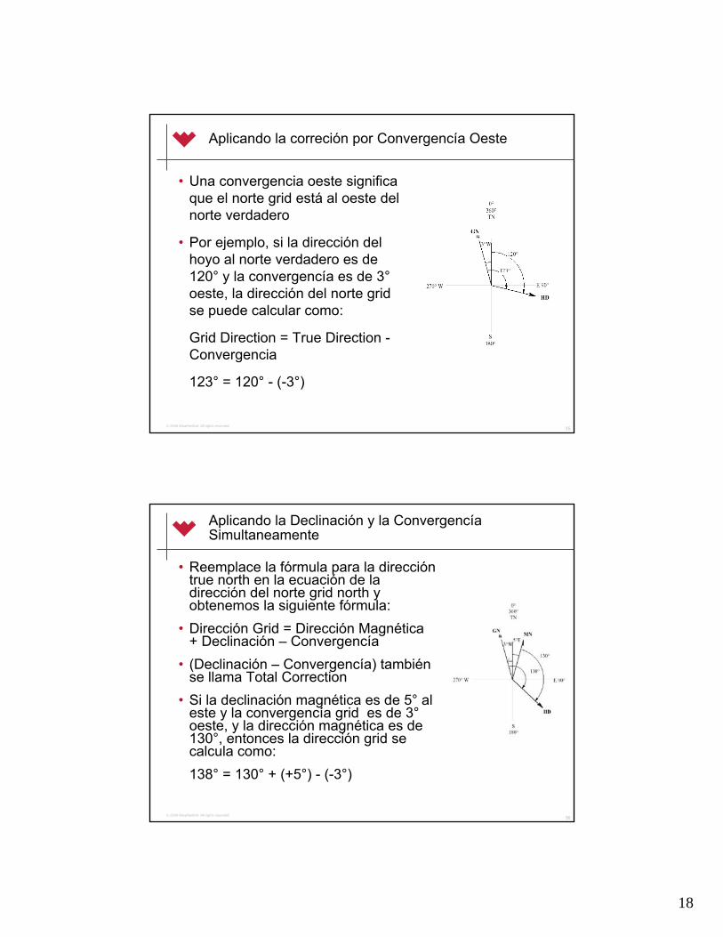
18
35© 2006 Weatherford. All rights reserved.
Aplicando la correción por Convergencía Oeste
• Una convergencia oeste significaque el norte grid está al oeste del norte verdadero
• Por ejemplo, si la dirección del hoyo al norte verdadero es de 120° y la convergencía es de 3°oeste, la dirección del norte grid se puede calcular como:
Grid Direction = True Direction -Convergencia
123° = 120° - (-3°)
36© 2006 Weatherford. All rights reserved.
Aplicando la Declinación y la ConvergencíaSimultaneamente
• Reemplace la fórmula para la direccióntrue north en la ecuación de la dirección del norte grid north y obtenemos la siguiente fórmula:
• Dirección Grid = Dirección Magnética+ Declinación – Convergencía
• (Declinación – Convergencía) tambiénse llama Total Correction
• Si la declinación magnética es de 5° al este y la convergencía grid es de 3°oeste, y la dirección magnética es de 130°, entonces la dirección grid se calcula como:138° = 130° + (+5°) - (-3°)

19
37© 2006 Weatherford. All rights reserved.
Comparación de la Proyecciones Grid (Cuadrícula)
• Las diferentes proyecciones genera vistas variables en lo que se refieren a la distancia, la forma, la escala y el área
38© 2006 Weatherford. All rights reserved.
Fuentes de Errores en la Inclinación en Tiempo Real
• Los factores siguientes pueden introducir errores en los valoresde inclinación del hoyo presentados al directional driller:
– Movimiento durante el survey (axial ó rotacional)
– Falla del acelerómetro ó asociada a la electrónica
– Calibración fuera de las especificaciones
– Precisión de la medición del Sensor
– Resolución transmisión en Tiempo Real

20
39© 2006 Weatherford. All rights reserved.
Fuentes de Errores en la Dirección (Azimuth) en Tiempo Real
• Los factores siguientes pueden introducir errores en los valores de dirección del hoyo presentados al directional driller directional driller:
– Interferencia Magnética (axial ó cross-axial)
– Falla de Magnetómetro falla de electrónica asociada
– Calibración fuera de especificaciones
– Acelerómetro “Dañado” (la inclinación y el highside toolface son partes del calculo de la dirección!)
– Error Matemático (con inclinaciones de 0° y de 90°)
– Precision de la medicion del Sensor
– Resolución de la transmision en tiempo real
– Dependiendo de los valores de Latitud, Inclinación, y Dirección del hoyo
– Una aplicacion incorrecta de la Declinación y/o la Convergencia
40© 2006 Weatherford. All rights reserved.
Comprobación de Calidad de la Inclinación
• La inclinación obtenida, concuerda con las acciones del perforador direccional?
• Se encuentra Gtotal dentro +/- 0.003 g de la Intensidad del Campo Gravitacional Local?
• Gtotal = (Gx2 + Gy2 + Gz2 ) 1/2
222 GzGyGxGtotal ++=

21
41© 2006 Weatherford. All rights reserved.
Comprobación de Calidad de Azimuth
• El azimut obtenido, concuerda con las acciones del perforador direccional?
• Se encuentra Btotal dentro +/- 350 nT de la Intensidad del Campo Magnético Local?
Btotal = (Bx2 + By2 + Bz2 ) ½
• Se encuentra Gtotal dentro +/- 0.003 g de la Intensidad del Campo Gravitacional Local?
222 BzByBxBtotal ++=
42© 2006 Weatherford. All rights reserved.
Criterio adicional para la aceptación de un survey
• Se encuentra el Angulo Magnético (Dip) calculado en +/-0.3º del Angulo Magnético Local ?
• MDIP utiliza valores de los acelerómetros y magnetómetros pero no es tan sensible al criterio de aceptación como Gtotaly Btotal.
• Es posible que MDIP este fuera de especificación pero Gtotal y Btotal no lo están.
• NOTA: MDIP no debe ser utilizado como criterio de aceptación para descalificar un survey si Gtotal y Btotal se encuentran dentro de las especificaciones
( )BtotalGtotalGzBzGyByGxBxASINMdip ∗∗+∗+∗= )()()(

22
43© 2006 Weatherford. All rights reserved.
Criterio de aceptación para un Survey
• Gtotal = (Gx2 + Gy2 +Gz2 ) 1/2
• Btotal = (Bx2 + By2 +Bz2 ) 1/2
(Bx * Gx) + (By * Gy) + (Bz * Gz)
• MDIP = ASIN {----------------------------------------------}
Gtotal * Btotal
Gtotal = Local Gravity ±0.003 g
Btotal = Local Field ± 350 nT
MDIP = Local Dip ± 0.3°
44© 2006 Weatherford. All rights reserved.
Сontrol de calidad del Survey Ejemplo #1
• Dada la siguiente data de survey, decida si se encuentraentre los límites de control de calidad
• Local References: Gtotal = 1.000 g Btotal = 58355 nT Mdip = 75.20°
INC AZ Gtotal Btotal MDip
3.72 125.01 1.0012 58236 75.25
• Basado en sus observaciones, son los valores de la inclinación y el azimuth aceptables?

23
45© 2006 Weatherford. All rights reserved.
Сontrol de calidad del Survey Ejemplo #1
• Dada la siguiente data de survey, decida si se encuentraentre los límites de control de calidad
• Local References: Gtotal = 1.000 g Btotal = 58355 nT Mdip = 75.20°
INC AZ Gtotal Btotal MDip
3.72 125.01 1.0012 58236 75.25
+0.0012 -119 -0.05
• Basado en sus observaciones, son los valores de la inclinación y el azimuth aceptables?
• SI / SI
46© 2006 Weatherford. All rights reserved.
Сontrol de calidad del Survey Ejemplo #2
• Dada la siguiente data de survey, decida si se encuentraentre los límites de control de calidad
• Local References: Gtotal = 1.000 g Btotal = 58355 nT Mdip = 75.20°
INC AZ Gtotal Btotal MDip
5.01 127.33 1.0009 58001 74.84
• Basado en sus observaciones, son los valores de la inclinación y el azimuth aceptables?
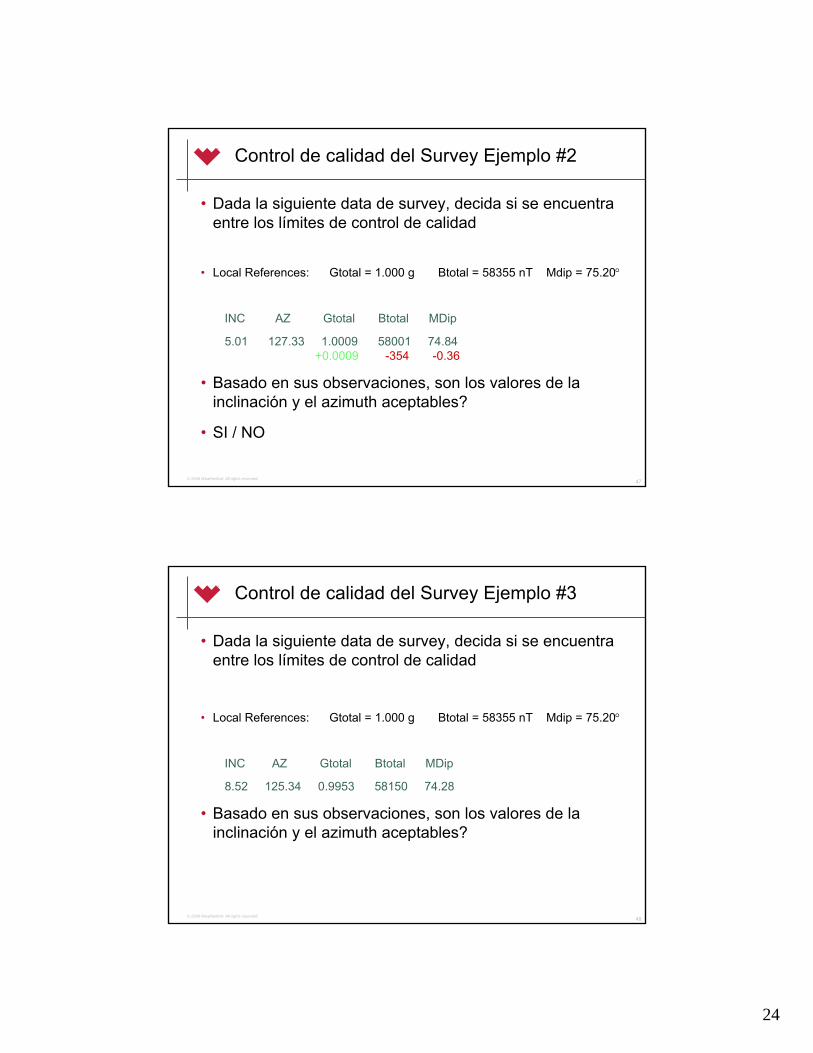
24
47© 2006 Weatherford. All rights reserved.
Сontrol de calidad del Survey Ejemplo #2
• Dada la siguiente data de survey, decida si se encuentraentre los límites de control de calidad
• Local References: Gtotal = 1.000 g Btotal = 58355 nT Mdip = 75.20°
INC AZ Gtotal Btotal MDip
5.01 127.33 1.0009 58001 74.84+0.0009 -354 -0.36
• Basado en sus observaciones, son los valores de la inclinación y el azimuth aceptables?
• SI / NO
48© 2006 Weatherford. All rights reserved.
Сontrol de calidad del Survey Ejemplo #3
• Dada la siguiente data de survey, decida si se encuentraentre los límites de control de calidad
• Local References: Gtotal = 1.000 g Btotal = 58355 nT Mdip = 75.20°
INC AZ Gtotal Btotal MDip
8.52 125.34 0.9953 58150 74.28
• Basado en sus observaciones, son los valores de la inclinación y el azimuth aceptables?

25
49© 2006 Weatherford. All rights reserved.
Сontrol de calidad del Survey Ejemplo #3
• Dada la siguiente data de survey, decida si se encuentraentre los límites de control de calidad
• Local References: Gtotal = 1.000 g Btotal = 58355 nT Mdip = 75.20°
INC AZ Gtotal Btotal MDip
8.52 125.34 0.9953 58150 74.28-0.0047 -205 -0.92
• Basado en sus observaciones, son los valores de la inclinación y el azimuth aceptables? NO / NO
50© 2006 Weatherford. All rights reserved.
Сontrol de calidad del Survey Ejemplo #4
• Dada la siguiente data de survey, decida si se encuentraentre los límites de control de calidad
• Local References: Gtotal = 1.000 g Btotal = 58355 nT Mdip = 75.20°
INC AZ Gtotal Btotal MDip
17.13 129.88 1.0120 57623 73.44
• Basado en sus observaciones, son los valores de la inclinación y el azimuth aceptables?

26
51© 2006 Weatherford. All rights reserved.
Сontrol de calidad del Survey Ejemplo #4
• Dada la siguiente data de survey, decida si se encuentraentre los límites de control de calidad
• Local References: Gtotal = 1.000 g Btotal = 58355 nT Mdip = 75.20°
INC AZ Gtotal Btotal MDip
17.13 129.88 1.0120 57623 73.44+0.0120 -732 -1.76
• Basado en sus observaciones, son los valores de la inclinación y el azimuth aceptables? NO / NO
52© 2006 Weatherford. All rights reserved.
Terminología usada en los Surveys

27
53© 2006 Weatherford. All rights reserved.
Terminología usada en los Surveys
• Survey Station
– Ubicación a lo largo del hoyodonde se toman lasmediciones direccionales
• True Vertical Depth (TVD)
– Es la proyeccion de la trayectoria del hoyo en el plano vertical
• Measured Depth (MD) Prof. Medida
– La distancia real recorrida a lo largo del hoyo
• Course Length (CL) Largo del Curso
– La distancia medidarecorrida entre dos survey stations
54© 2006 Weatherford. All rights reserved.
Terminología usada en los Surveys
• Horizontal Displacement (HD) / Desplazamiento Horizontal
– La Proyección del hoyo en el planohorizontal
– La distancia horizontal desde el wellhead hasta la ultima survey station
– Tambien se le llama Closure ( Cierre)
• Latitud (Northing)
– La distance recorrida en la direccionnorte-sur en el plano horizontal
– Al Norte es positiva, al Sur es negativa
• Departure (Easting) Longitud
– La distance recorrida en la direccioneste-oeste en el plano horizontal
– Este es positiva, Oeste es negativa

28
55© 2006 Weatherford. All rights reserved.
Terminología usada en los Surveys
• Target Direction / Dirección del Objetivo
– La dirección en la propuesta del pozo
• Vertical Section (VS) / Sección V.– La proyección del
desplazamiento horizontal a lo largo de la dirección del objetivo/target direction
– La distancia horizontal recorridadesde el wellhead al target a lo largo del target direction
• Dogleg Severity (DLS) / Severidad de Pata’d’perro
– Un estimado normalizado (porejemplo en grados/100 pies) de toda la curvatura de unatrayectoria dada entre dos survey stations consecutivas
56© 2006 Weatherford. All rights reserved.
Terminología usada en los Surveys
• Para determinar la sección vertical se deben conocer de antemanoel closure ( el desplazamiento horizontal), la direccion de cierre(closure direction), y el target direction (dir. Objetivo)
• La vertical section es un producto del desplazamiento horizontal por la diferencia entre la dirección del cierre (closure) y la del objetivo (target). Función Trigonométrica
VS = HD *cos (Target Direction –Closure Direction)

29
57© 2006 Weatherford. All rights reserved.
Proyección Vertical
• En la proyeccion vertical el perforador direccionalplotea la TVD versus la Sección Vertical
• La trayectoria del hoyo debepasar a travéz del espesor o cilindro del objetivo a lo largo de la dirección de la sección vertical de manerade que pueda alcanzar el objetivo en el plano
Kickoff Point
True
Ver
tical
Dept
h
Vertical Section
Tangent
Build Section
Locked in Section
58© 2006 Weatherford. All rights reserved.
Proyección Horizontal
• En la proyección horizontal el perforador direccional Plotea la Latitud versus Departure/Longitud
• La trayectoria del hoyo debe pasara travéz del radio del objetivohorizontal a lo largo de la dirección del objetivo propuestade menera que alcance el mismoen el plano horizontal
N
E
Latitude
Departure
ProposalDirection
Closure
Vertical Section
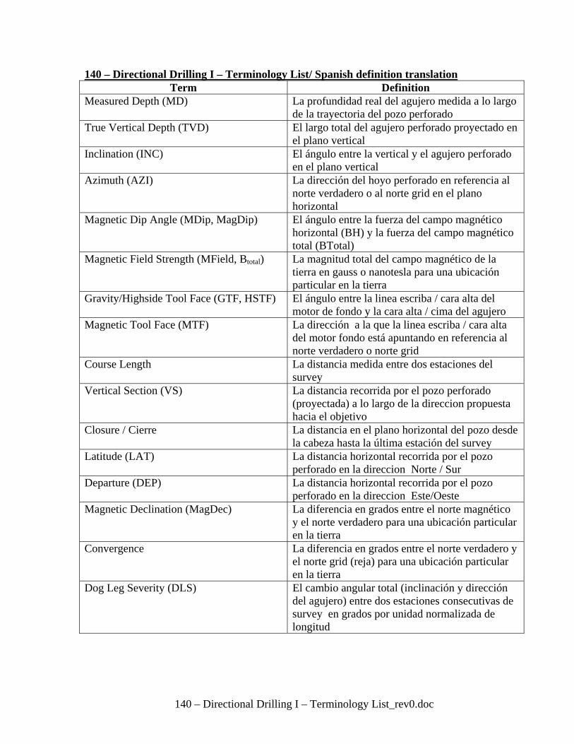
140 – Directional Drilling I – Terminology List_rev0.doc
140 – Directional Drilling I – Terminology List/ Spanish definition translation Term Definition
Measured Depth (MD) La profundidad real del agujero medida a lo largo de la trayectoria del pozo perforado
True Vertical Depth (TVD) El largo total del agujero perforado proyectado en el plano vertical
Inclination (INC) El ángulo entre la vertical y el agujero perforado en el plano vertical
Azimuth (AZI) La dirección del hoyo perforado en referencia al norte verdadero o al norte grid en el plano horizontal
Magnetic Dip Angle (MDip, MagDip) El ángulo entre la fuerza del campo magnético horizontal (BH) y la fuerza del campo magnético total (BTotal)
Magnetic Field Strength (MField, Btotal) La magnitud total del campo magnético de la tierra en gauss o nanotesla para una ubicación particular en la tierra
Gravity/Highside Tool Face (GTF, HSTF) El ángulo entre la linea escriba / cara alta del motor de fondo y la cara alta / cima del agujero
Magnetic Tool Face (MTF) La dirección a la que la linea escriba / cara alta del motor fondo está apuntando en referencia al norte verdadero o norte grid
Course Length La distancia medida entre dos estaciones del survey
Vertical Section (VS) La distancia recorrida por el pozo perforado (proyectada) a lo largo de la direccion propuesta hacia el objetivo
Closure / Cierre La distancia en el plano horizontal del pozo desde la cabeza hasta la última estación del survey
Latitude (LAT) La distancia horizontal recorrida por el pozo perforado en la direccion Norte / Sur
Departure (DEP) La distancia horizontal recorrida por el pozo perforado en la direccion Este/Oeste
Magnetic Declination (MagDec) La diferencia en grados entre el norte magnético y el norte verdadero para una ubicación particular en la tierra
Convergence La diferencia en grados entre el norte verdadero y el norte grid (reja) para una ubicación particular en la tierra
Dog Leg Severity (DLS) El cambio angular total (inclinación y dirección del agujero) entre dos estaciones consecutivas de survey en grados por unidad normalizada de longitud

Etiquete el diagrama
A
B
D
E
Ubique los siguiente terminos en su linea apropiada. TVD Kick Off Point Vertical Section Build Section Tangent section
A: B: C: D: E:
Vista de
Perfil C

N
E
Trayectoria
C
B
E
Ubique los siguiente terminos en su linea apropiada. Vertical Section Azimuth Latitude Vertical Section Closure Departure
A: B: C: D: E:
Vista Horizontal
A
D
Trayectoria Propuesta

Nombre: ___________________
Convierta los siguiente formatos de cuadrante y azimuth: 1. azimuth 85 quadrant 2. azimuth 199 quadrant 3. azimuth 335 quadrant 4. azimuth 255 quadrant 5. azimuth quadrant S 45 W 6. azimuth quadrant N 75 E 7. azimuth quadrant S 55 E 8. azimuth quadrant N 15 W Convierta las siguientes coordenadas rectangulares en coordenadas polares: Muestre los calculos de cada uno.
9. 55.57’ N 73.57’ E Closure = __________Azimuth = _________ 10. 55.57’ S 73.57’ W Closure = __________Azimuth = __________ 11. _____ N ______E Closure = 56.13 Azimuth = 296.45 12. _____N ______E Closure = 45.75 Azimuth = 109.14

SingleNo.
SingleLength
BitDepth
SurveyDepth Inc. Azm. Slide
SeenB.U.R./Ft Slide
B.U.R./100 '
INC @Bit
T.F.Setting From To Total
Slide
Slide Above/ Below
Slides WorksheetBHA # ___________

DD Trig Calculations_rev4.doc
Calculation: Slide vs Rotate Distance to Slide = (Joint Length) * ((BR Proposed – BR Rotating) / (BR Sliding – BR Rotating)) Distance to Slide = (BR Required / BR Actual) * (Joint Length) Build Rate Required = [(Sin Inc TGT) – (Sin Inc Present)] * 1719m (or 5,730’) TVD TGT – TVD Present Rate of Build = ((Cos TF Setting) * (Expected D/L Motor) * (Meters Set)) / 30m (or 100’) Rate of Turn = ((Sin TF Setting) * (Expected D/L Motor) * (Sin Inc)) / 30 m (or 100’) BR Actual = (Inc Present – Inc Previous) / Course Length Bit Inclination = (BR Actual * Bend to Bit Distance) + Inc Present Radius = 1719 / BR Proposed (or 5,730’) DLS = (30m or 100’ / CL) x cos-1[(sinINC1 x sinINC2) x cos(AZI2-AZI1) + (cosINC1 x cosINC2)] Survey to Survey Calculations Course Deviation = Course Length * (Sin IncAVG) Latitude = Course Deviation * (Cos AzmAVG) Departure = Course Deviation * (Sin AzmAVG) TVD = Course Length * (Cos IncAVG) Vertical Section = Closure Length * (Cos (AzmTGT – AzmClosure)) IncAVG = (IncPresent + IncPrevious) / 2 AzmAVG = (AzmPresent + AzmPrevious) / 2 Closure Direction = Atan (Departure/Latitude) Closure = (Latitude2 + Departure2)1/2

881 2 3 4 5 6 7 8 9 10 11 12 13 14 15 16
Survey Depth Inclination Azimuth Course
LengthAverage
InclinationAverage Azimuth
Change in TVD
TVD Change in Displacement
Change in Latitude
Latitude Change in Departure
Departure Closure Direction Closure Vertical Section
(m) Inc Az CL Ave Inc Ave Az 4*Cos (5) TVD + 7 4*Sin (5) 9*Cos (6) Lat + 10 9*Sin (6) Dep + 12 Atan(13/11) sqrt(11^2+13^2) 15*Cos(PD-14)
1 1039.60 1.81 69.92 1039.43 6.17 10.56 10.77
2 1045.00 3.03 80.47 5.40 2.42 75.20 5.40 1044.83 0.23 0.06 6.23 0.22 10.78 59.98 12.45 10.99
3 1049.40 4.02 89.06 4.40 3.53 84.77 4.39 1049.22 0.27 0.02 6.25 0.27 11.05 60.50 12.70 11.26
4 1058.80 7.85 89.65 9.40 5.94 89.36 9.35 1058.57 0.97 0.01 6.26 0.97 12.02 62.48 13.56 12.23
5 1068.66 8.30 89.90
6 1078.54 9.4 90.12
7 1088.29 10.2 90.05
8 1097.61 14.6 89.8
9
10
11
12
13
14
15
16
17
18
19
20
21
22
23
24
25
26
27
28
29
30
Proposal Direction:Average Angle Survey Calculation Sheet

881 2 3 4 5 6 7 8 9 10 11 12 13 14 15 16
Survey Depth Inclination Azimuth Course
LengthAverage
InclinationAverage Azimuth
Change in TVD
TVD Change in Displacement
Change in Latitude
Latitude Change in Departure
Departure Closure Direction Closure Vertical Section
(ft) Inc Az CL Ave Inc Ave Az 4*Cos (5) TVD + 7 4*Sin (5) 9*Cos (6) Lat + 10 9*Sin (6) Dep + 12 Atan(13/11) sqrt(11^2+13^2) 15*Cos(PD-14)
1 3410.75 1.81 69.92 3410.193 20.24 34.65 35.33
2 3428.47 3.03 80.47 17.72 2.42 75.20 17.70 3427.89 0.75 0.19 20.43 0.72 35.37 59.98 40.85 36.06
3 3442.90 4.02 89.06 14.44 3.53 84.77 14.41 3442.30 0.89 0.08 20.51 0.88 36.25 60.50 41.65 36.95
4 3473.74 7.85 89.65 30.84 5.94 89.36 30.67 3472.98 3.19 0.04 20.55 3.19 39.44 62.48 44.47 40.13
5 3506.09 8.30 89.90
6 3538.51 9.4 90.12
7 3570.49 10.2 90.05
8 3601.07 14.6 89.8
9
10
11
12
13
14
15
16
17
18
19
20
21
22
23
24
25
26
27
28
29
30
Proposal Direction:Average Angle Survey Calculation Sheet

1 2 3 4 5 6 7 8 9 10 11 12 13 14 15 16Survey Depth Inclination Azimuth Course
LengthAverage
InclinationAverage Azimuth
Change in TVD
TVD Change in Displacement
Change in Latitude
Latitude Change in Departure
Departure Closure Direction Closure Vertical Section
MD Inc Az CL Ave Inc Ave Az 4*Cos (5) TVD + 7 4*Sin (5) 9*Cos (6) Lat + 10 9*Sin (6) Dep + 12 Atan(13/11) sqrt(11^2+13^2) 15*Cos(PD-14)
1
2
3
4
5
6
7
8
9
10
11
12
13
14
15
16
17
18
19
20
21
22
23
24
25
26
27
28
29
30
Proposal Direction:Average Angle Survey Calculation Sheet

Directional Drilling Handbook Calculating The Build Rate to Target
Inclination and TVD
This document is considered UNCONTROLLED and shall not be updated unless stamped with a green Controlled Copy stamp.
QF-GEN-F000? Call Rob for number. Rev. 0
L3-COM-CA-QF-GEN-F000?
Page 1 of 1
How to calculate the Build Rate to Target Inclination and TVD The following is the formula that is used when landing a horizontal well. The formula calculates how quickly the well must build in order to reach a target inclination at the desired TVD. This build rate does not hit a target, rather it reach a desired inclination by a desired TVD. The build rate is dependent only on the current inclination and TVD, and the target inclination and TVD. When using Wellz, this build rate is located on the right side of the Straight Line Projection screen in the small box.
Formula:
Sin of Target Inclination – Sin of Present Inclination Target TVD – Present TVD X 1719 = BR
Example # 1 Present Inc = 34.22˚ Present TVD = 523 Meters Target Inc = 90.00˚ Target TVD = 650 Meters Sin 90˚ – Sin 34.22˚ 650m – 523m x 1719 = 1 - .5624 127 x 1719 = 5.92˚/30 meters
Example # 2 Present Inc = 54.85˚ Present TVD = 1149 Meters Target Inc = 85.00˚ Target TVD = 1188 Meters Sin 85˚ – Sin 54.85˚ 1188m – 1149m x 1719 = .9962 - .8176 39 x 1719 = 7.87˚/30 meters

Directional Drilling Handbook Calculating the Radius of an Arc
This document is considered UNCONTROLLED and shall not be updated unless stamped with a green Controlled Copy stamp.
QF-GEN-F000? Call Rob for number. Rev. 0
L3-COM-CA-QF-GEN-F000?
Page 1 of 2
Calculating the Radius of an Arc One important measurement used in directional drilling is the radius of an arc. We may not see this number, or have been known to directly calculate it, but it is there behind the math. It is important to know how to calculate this number in order to make some basic advanced math calculations. The following pages describe how to calculate the radius of an arc. This formula can be used to either calculate:
1. How fast a curve has to build from vertical to be 90˚ in a given TVD.
or
2. How many meters it will take to build to 90˚ from 0˚ using a given build rate. Unfortunately these are the only two places this formula can be used. As mentioned earlier, the radius that is calculated can be used in the future to calculate things like TVD used in a partial build and vertical section that is gained during a build section.
KOP
90˚
TVD
Displacement
Arc Radius

Directional Drilling Handbook Calculating the Radius of an Arc
This document is considered UNCONTROLLED and shall not be updated unless stamped with a green Controlled Copy stamp.
QF-GEN-F000? Call Rob for number. Rev. 0
L3-COM-CA-QF-GEN-F000?
Page 2 of 2
Standard Formula Metric Formula Example # 1 in metric How many meters TVD will it take to build to 90˚ from vertical using a 12˚/30 meter build rate? Example # 2 in metric If a client wants to come out of a vertical well using a whipstock and be horizontal in 40 meters TVD, how fast must they build?
R = 180 x 100’ π
R = 180 x 30 m π
BUR BUR R = R =
R (TVD) = R (TVD) = 5730’ BUR
1719 m BUR
or or
5730’ R (TVD)
BUR = BUR = 1719 m R (TVD)
Radius (TVD) = 1719 12 Radius (TVD) = 143.25 m
BUR = 1719 40 BUR = 42.975 ˚/30 meters

Directional Drilling Handbook Calculating the Change in TVD during
a Build Section
This document is considered UNCONTROLLED and shall not be updated unless stamped with a green Controlled Copy stamp.
QF-GEN-F000? Call Rob for number. Rev. 0
L3-COM-CA-QF-GEN-F000?
Page 1 of 1
Calculating the Change in TVD during a Build Section
Change In TVD During The Build Section Step 1. Step 2. Calculating the Radius Calculating the TVD of Build Section TVD = 90.81 meters Radius = 214.88 Meters
Change In TVD
Change In Disp.
Radius
Measured Depth
KOP
EOB
Well Information
Build Rate - 8º/30m KOP – 500 m
EOB Angle - 25º
= Sine of Final Angle x Radius of Arc
Radius = 1719 meters 8º / 30 meters
TVD = Sin 25º x 214.88 meters

Directional Drilling Handbook Calculating the Change in Displacement
during a Build Section
This document is considered UNCONTROLLED and shall not be updated unless stamped with a green Controlled Copy stamp.
QF-GEN-F000? Call Rob for number. Rev. 0
L3-COM-CA-QF-GEN-F000?
Page 1 of 1
Calculating the Change in Displacement during a Build Section
Change In Displacement During the Build Section Step 1. Step 2. Calculating the Radius Calculating the Change in Displacement Radius = 214.88 Meters
Change In TVD
Change In Disp.
Radius
Measured Depth
KOP
EOB
Well Information
Build Rate - 8º/30m KOP – 500 m
EOB Angle - 25º
= Radius – (Cos of final angle x Radius)
Radius = 1719 meters 8º / 30 meters
Change in Disp. = 214.88 – (cos 25º x 214.88)
Change in Disp. = 214.88 – (.9063 x 214.88)
Change in Disp. = 20.13

1
© 2006 Weatherford. All rights reserved.
Directional Drilling I
Revision 3
Ajuste por la elevación del KB
© 2006 Weatherford. All rights reserved.
Ajustando la Elevación del KB
• El PD 261 perforó una sección de construcción en un proyecto. Debido a al tamaño pequeño del equipo, este se puede rasgar desarmar y mover más rápidamente que un equipo más grande. Usando esto como una ventaja, este proyecto perforará las secciones de construcción con el equipo más pequeño, entubará y lo cementará, entonces lo moveráfuera. Y un rato más tarde el equipo grande (PD 511) que es capaz de perforar mucho más profundo se moverá hacia este pozo y completará la sección lateral. Cuando el PD 511 mueva hacia la sección de construcción de este pozo, el casing y el cemento estará duro. Esto minimizará el tiempo de espera y el coste para el cliente. Todo lo que el PD511 tiene que hacer es armar y comenzar la perforación direccional. Los perforadores direccionales tienen que importar los surveys de la sección de construcción y ajustarlos por la diferencia de altura antes de que comenzar.
2.5 Meters
PD 261Build Rig
PD 511Lateral Rig
90°

2
© 2006 Weatherford. All rights reserved.
•Si no se realiza ningún ajuste a la profundidad medida a los surveys de la seccion de construcción habrávarios problemas:
•Cuando la cañería se mete en el agujero, la zapata y el cuello flotador parecerán estar 2.5 metros más profundo que de donde realmente están. Esto sería correcto desde que el equipo es más alto, y unos 2.5 metros adicionales de cañería se necesitan de ser corrido en el agujero para compensar por esto. Mostrado en ROJO•Los surveys que se tomaron en la sección de construcción no se aparearán con las inclinaciones en el equipo lateral. Porque se necesitan los 2.5 metros extras de cañería, cuando el equipo de la la seccion de construcción estaba en las 90°, el equipo de la lateral se regresa unos 2.5 metros, posiblemente donde hay 88°. De nuevo, mostrado en ROJO
2.5 Meters
PD 261Build Rig
PD 511Lateral Rig
90° 88°
MD = 750m
MD = 750m
Ajustando la Elevación del KB
© 2006 Weatherford. All rights reserved.
•Si la TVD tampoco se ajusta, entonces habrá un problema mayor asociado con esto:
•La TVD es calculada desde la mesa / suelo del equipo (desde la profundidad del bushing del kelly, también se llamó la profundidad del KB). Cuando no hay ningún ajuste hecho, el archivo lateral estará superior en 2.5 metros mas que lo requerido. Sin los ajustes, el equipo estará taladrando en la zona errada (mostrado en AMARILLO). La TVD (los números) serán iguale que en el equipo de la seccion de contrucción, pero debido a la diferencia de 2.5 metros entre los dos equipos, la zona es ahora 2.5 metros mas somera que en el equipo de la construccion.
•¡Recuerde, la TVD es calculada desde el KB!
2.5 Meters
PD 261Build Rig
PD 511Lateral Rig
2.5 Meters
TVD 553 Meters
TVD 553 Meters
KB
KB
Ajustando la Elevación del KB

3
© 2006 Weatherford. All rights reserved.
•Cuando la profundidad medida y la TVD se ajustan apropiadamente:
•Porque se agregaron 2.5 metros a la profundidad medida (mostrado al final de la curva en VERDE), hay bastante carrera de la cañería en el agujero para alcanzar el cuello y zapata a la profundidad medida apropiada. También, los surveys de la seccion de construccioncoinciden ahora con los surveysdel taladro en la seccion lateral.
•También se agregaron 2.5 metros a la TVD, Se muestra más abajo ya corregido en AMARILLO. Haciendo esto el equipo está taladrando ahora más profundamente 2.5 metros en TVD (como debe ser) y en la zona de produccion correcta.
2.5 Meters
PD 261Build Rig
PD 511Lateral Rig
+ 2.5 Meters
TVD 553 Meters
TVD 553 Meters
90°
90°
+ 2.5 m
Ajustando la Elevación del KB
© 2006 Weatherford. All rights reserved.
•¡Cuando se mudan los surveysde un equipo a otro, la MD (profundidad medida) y la TVD (profundidad vertical verdadera) los dos deben ajustarse por la misma cantidad (diferencia en KB) para que los surveys estencorrectos! Esto va para los surveys tomados en el equipo de la seccion de construccion para el equipo de la lateral, para el del equipo original para el equipo de la reentrada, o el de la propuesta en papel al de la propuesta del equipo real. Si el nuevo equipo es más alto, la diferencia en KB se agrega a los dos: la profundidad medida y TVD. Si el nuevo equipo es más bajo en KB, la diferencia en KB se substrae de la profundidad medida y TVD.
•Como una nota final, recuerde escribir las Elevaciones KB correctas bajo la “Informacion de Encabazado“ (Header Info) en el programa de Wellz.
2.5 Meters
PD 261Build Rig
PD 511Lateral Rig
TVD 553 Meters
TVD 555.5 Meters
MD = 750m
MD = 752.5m
Ajustando la Elevación del KB

4
© 2006 Weatherford. All rights reserved.
•En el Programa de Wellz hay una página de encabezado. Aqui es donde toda la información crítica sobre el pozo se entra. Este es una foto de cómo luce la página del encabezado.
•En esta página de encabezado del programa de Wellz, se muestra en Amarillo donde es que el KB correcto se escribe. Si estátrabajando con dos archivos abra al mismo tiempo, (la propuesta y el archivo de surveys) ambos archivos del pozo tienen que tener los mismos números. Si no lo hiciera falsamente pudiera creer que está delante de la línea o detrás de la línea simplemente porque estos dos números no son iguales. ¡Ésta es información crítica que tiene que ser entrada!
Header - Software Wellz™
© 2006 Weatherford. All rights reserved.
Original Rig Segundo Rig Ajuste
KB Elevation 532.20 532.90
Ejemplo de Ajuste de KB

5
© 2006 Weatherford. All rights reserved.
Original Rig Segundo Rig Ajuste
KB Elevation 532.20 532.90 +.70 m
+ .70 Metros son añadidos para ambas profundidad medida y TVD.
Ejemplo de Ajuste de KB
© 2006 Weatherford. All rights reserved.
Original Rig Segundo Rig Ajuste
KB Elevation 532.20 m 532.90 m +.70 m
KB Elevation 788.10 ft 790.10 ft + 2 ft
+ 2 Metros son añadidos para ambas profundidad medida y TVD.
Ejemplo de Ajuste de KB

6
© 2006 Weatherford. All rights reserved.
Original Rig Segundo Rig Ajuste
KB Elevation 532.20 m 532.90 m +.70 m
KB Elevation 788.10 ft 790.10 ft + 2 ft
KB Elevation 990.00 ft 985.00 ft - 5 ft
- 5 Metros son sustraidos a ambas profundida medida y TVD.
Ejemplo de Ajuste de KB
© 2006 Weatherford. All rights reserved.
Original Rig Segundo Rig Ajuste
KB Elevation 532.20 m 532.90 m +.70 m
KB Elevation 788.10 ft 790.10 ft + 2 ft
KB Elevation 990.00 ft 985.00 ft - 5 ft
KB Elevation 201.50 m 199.10 m - 2.4 m
- 2.4 Metros son sustraidos a ambas profundida medida y TVD.
Ejemplo de Ajuste de KB

7
© 2006 Weatherford. All rights reserved.
• Ahora que sabemos ajustar nuestros archivos de pozos, es tiempo de mostrar la manera fácil de ajustar el archivo del pozo en Wellz. Usted sabe cuánto hay que ajustar, ahora sólo permita al programa hacer el trabajo.
• Cuando este en Wellz, vaya a:
• Tools• Shift or Rotate Well• Una vez que seleccione la opcion “Shift or
Rotate Well”, la siguiente pantalla aparecerá
• Todo lo que necesita hacer es entrar el montopor el cual el pozo va a ser ajustado en ambascasillas la de “Change Measured Depth” (MD) y la “Change TVD”. Una vez completada, clickee en el boton de OK y el pozo dondeeste se ajustara. Esto aplica solamente parala informacion en la pantalla se surveys. KB y la elevacion del terreno ( ground elevation ) en la pantalla del encabezado (header) debe ser cambiada manualmente. Recuerde, el ajustedel pozo con “Shift the Well” no cambia la informacion del Header!
Wellz™ Software – Ajuste (Shifting MD & TVD)

Computalog Drilling Services
21
90
70
60
50
40
30
20
10
10 20 30 40 50 60 70 80 90
ZONE 190
70
60
50
40
30
20
10
ZONE 290
70
60
50
40
30
20
10
ZONE 3
10 20 30 40 50 60 70 80 90 10 20 30 40 50 60 70 80 90
Empirical Data Charts for Nonmagnetic Drill Collar Spacing
Direction Angle from Magnetic N or S Direction Angle from Magnetic N or S Direction Angle from Magnetic N or S
Compass SpacingArea A 18’ collar: 1’ to 2’ below centerArea B 30’ collar: 3’ to 4’ below centerArea C tandem 18’+25’: center of
bottom collar
Compass SpacingArea A 30’ collar: 3’ to 4’ below centerArea B 60’ collar: at centerArea C 90’ collar: at center
Compass SpacingArea A 60’ collar: at centerArea B 60’ collar: 8’ to 10’ below centerArea C 90’ collar: at center
80 80 80

HOW TO DETERMINE
MUD PULSE & EM
TOOLFACE OFFSETS
Toolface Offset Determination 3-1

NEGATIVE PULSE OFFSET TOOL FACE
OFFSET TOOL FACE (OTF) SHEET
This sheet is possibly the most important form that must be filled out correctly. All other work and activity performed by the MWD Operator means naught if the well must be plugged back with cement because of an incorrect OTF calculation (or the correct OTF not being entered into the TLW 2.12 software). Ensure that the OTF calculation is correct, entered into TLW 2.12 correctly and verified by the Directional Driller.
The procedure for measuring the OTF is as follows:
1. Measure in a clockwise direction the distance from the MWD high side scribe to the motor high side scribe. Record this length into the OTF work sheet as the OTF distance. In the following example, this value is 351 mm.
2. Measure the circumference of the tubular at the same location where the OTF distance is being measured. Record this length into the OTF work sheet as the Circumference of Collar.
3. Calculate the OTF angle using the following formula:
OTF Angle= OTF Distance x 360 Collar Cirumference
From the above example, if the collar circumference is 500 mm,
OTF Angle= (351/500) x 360 = 0.702 x 360 = 252.72o
A sample form is as follows:
3-2 inationToolface Offset Determ

NEGATIVE PULSE OFFSET TOOL FACE (O.T.F. MEASUREMENT)
Well Name: Enter in the Well Name here Date: Enter in date OTF taken
LSD: Enter in the LSD here Time: Enter in time OTF taken
Job #: Enter in the MWD job number here Run #: Enter in the run number
PROPER DIRECTION OF OTF
TOP VIEW OF MWD
MWD SCRIBE
MEASUREMENT
MOTOR SCRIBE (HIGH SIDE)
351 mm
500 mm
252.72 degrees
252.72 degrees
Directional Driller(s)
O.T.F. Distance (Anchor Bolts to Collar Scribe):
Circumference of Collar:
O.T.F. Angle (Distance / Circumference) x 360:
O.T.F Angle entered into Computer as:
O.T.F. Distance measured by: Both MWD Operator Names
O.T.F. Calculated by: Both MWD Operator Names
O.T.F Entered into computer by: Both MWD Operator Names
O.T.F. Measurement and calculation Witnessed by: Name(s)
Toolface Offset Determination 3-3

NEGATIVE PULSE OFFSET TOOL FACE
Toolface O3-4
252.72
ffset Determination

POSITIVE PULSE Toolface Offset
INTERNAL TOOL FACE OFFSET (TFO) SHEET
Note: For the positive pulse MWD, the OTF is zero. Ensure that a zero OTF has been entered into TLW 2.12. The positive Tool Face Offset (TFO) sheet entries are as follows:
1. Positive Pulse Pulser Set to High Side / Directional Driller: Enter the names of the MWD Operator and Directional Driller respectively.
2.Positive Pulse T.F.O. from PROGTM: Enter the T.F.O. value reported from thehigh side tool face calibration from TLW 2.12.
TFO internal toolface offset
3-5 inationToolface Offset Determ

POSITIVE PULSE T.F.O. MEASUREMENT
Date: Enter in date OTF takenW
LSD: Time: taken
number
ell Name: Enter in the Well Name here
Enter in n time OTF the LSD here Enter i
Job #: Enter in the MWD job number here Run #: Enter in the run
ROTATE PULSER TO HIGH SIDE
PULSER KEY WAY
PROPER DIRECTION OF TFO MEASUREMENT
DAS HIGH SIDE TAB
N
163.25 degrees
0.00 degrees
/ /
nd M
Signature of Directional
Positive Pulse Pulser Se Witness t to High Side: ame of MWD hand
Directional Driller: ctional hand Witness Name of Dire
Positive Pulse T.F.O. from PROGTM:
Gravity Tool Face (gtface) Should Equal Zero:
Motor Adjustment: 2.12 G degrees setting
Alignment of Mule Shoe Sleeve Key to Motor Sc e: Name of 2rib WD hand Witness
O.T.F.=0, Entered in Name of MWD hand to Computer by:
All Calculations Witnessed by: Driller
Toolface Offset Determination 3-6
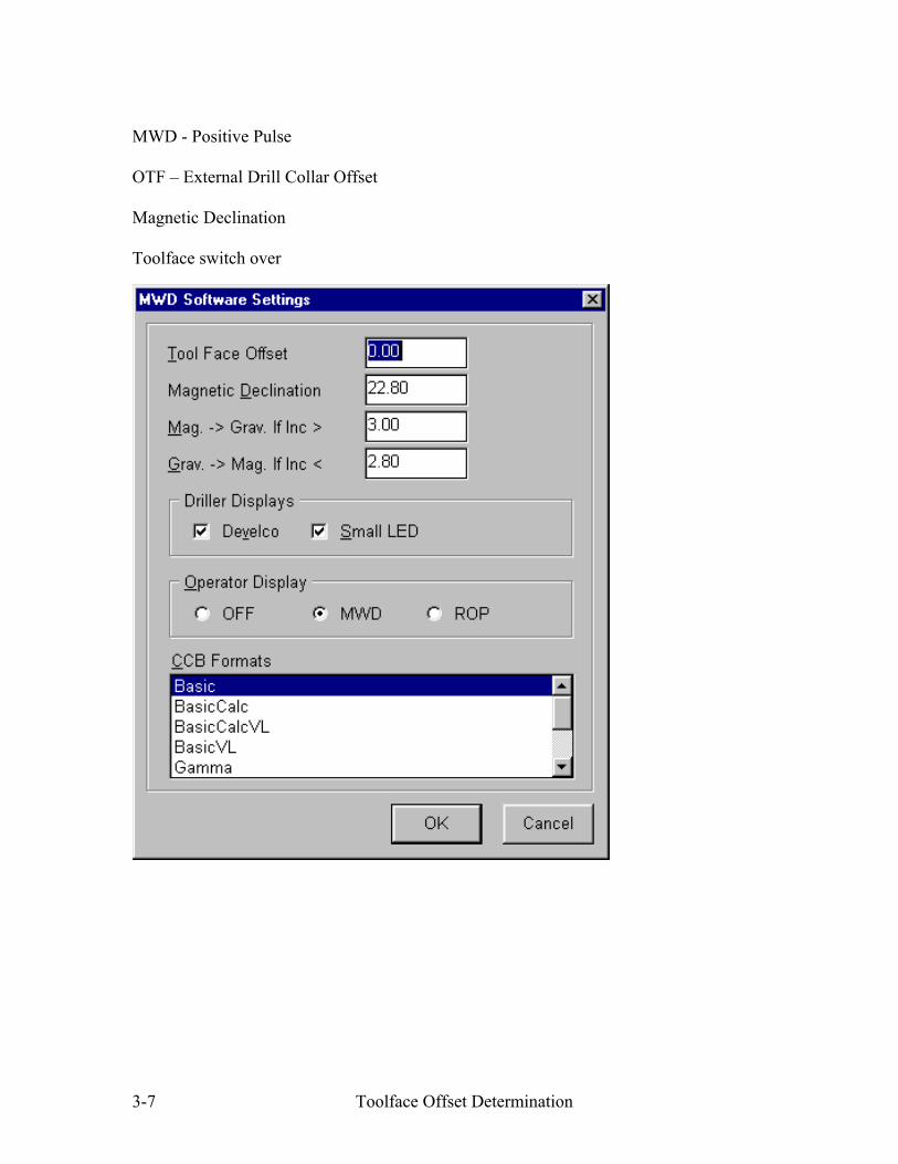
MWD - Positive Pulse
OTF – External Drill Collar Offset
Magnetic Declination
Toolface switch over
Toolface Offset Determination 3-7

MEMO
i iContents of this document are property to COMPUTALOG and may not be reproduced or otherw se used in any manner whatsoever w thout prior written permission of COMPUTALOG
From: MWD and Directional Coordinators
To: All MWD and Directional Field Supervisors
CC: Bill Beattie, Don Cappelle, Paul Timmins, Marc Lahitte, Chris Hartley, Doug Hamilton
Date: April 04, 2003
Re: New OTF sheet
As many of you are aware, we had several OTF measurement errors this past winter which greatly affected our bottom line. Every time we face such problems we try to improve our procedures for measuring the OTF and try to implement stringent measures, yet we still continue to have such major incidents. One of the new measures that we had implemented recently is to have all MWD Field Supervisors phone in the Coordinator on call and report the numbers measured and entered in the computer. This is in addition to the fact that you have to fax/e-mail the completed OTF sheets to the office as soon as the correct measurements and data input have been done. Such procedure will be followed from now on until further notice. We are also introducing this new OTF sheet, which is more detailed with the intent of raising awareness of the extreme importance of this procedure. You all have to understand that the OTF is one the most important steps in your jobs, regardless whether you are a Directional Driller or a MWD Operator.
On the bottom of the sheet is stated in big letters that the responsibility of the correct OTF measurement and input in the computer is actually a shared responsibility between the MWD Operators and the Directional Drillers. We need to make it very clear for all of you: when the OTF is calculated wrong or entered wrong in the computer, it’s affecting the whole Company, not just one department. The Directional Drillers have to ensure that not only the measurement is done correctly, but part of their responsibility is to check that the correct numbers are entered in the computer. If the MWD On-line computer has to be changed for any reason during the job, please ensure that the same numbers are entered in the appropriate place in the new computer.
In light of the recent incidents, it is clear that we need some accountability from all the Field Supervisors. Effective immediately, any OTF measurement error resulting in lost rig time will result in loss of bonus and/or termination of employment.
There is no excuse for OTF errors. All field supervisors have the knowledge and skills to complete this task properly. By adhering to the set procedures we will avoid these preventable incidents and eliminate the liability associated with them.
Issue: 1 Page: 1 / 1 Rev.: 1

PROPER DIRECTION OF O.T.F MEASUREMENT
G4 MWD OFFSET TOOL FACE (O.T.F. MEASUREMENT)
Well Name: Date:
LSD: Time:
Job #: Run #:
MWD SCRIBE
TOP VIEW OF M.W.D.
MOTOR SCRIBE (HIGH SIDE)
YES NO Initial: YES NO Initial: YES NO Initial: YES NO Initial:
A) Distance from MWD Scribe to Motor Scribe: Always measured clockwise B) Circumference of collar:
Tool Face Offset DC = (Distance A) x 360 = O.T.F.
Zero Tool Face Offset G4:
TF offset as seen on the Main GX (3.3) screen:
(Circumference B)
mm or inches
If you answered "NO" to ANY of the above questions, call your coordinator immediately.
Is the Proper Run #, Date & Connection time for the tool entered in "Job data" for this run? Did the "Zero toolface offset G4" in "Job data" = "0" before the G4 internal offset was recorded?
Did the "Tool face offset DC" in "Job data" = "0" before the G4 internal offset was recorded?
O.T.F. Measured and calculated by (print and sign): O.T.F. Entered into the computer by (print and sign):
O.T.F. Measurement and calculation witnessed by Directional Driller (print and sign):
Did the Directional driller witness you entering the O.T.F. into your on-line computer
In "Main Gx" on your on-line computer under the menu "Setup", sub-menu "Job data":
mm or inches
If you answered "YES" to ALL of the above questions, you may continue.
degrees
Enter in "Job data", same as: Zero Toolface Offset G4.
Enter in "Job data", same as: Tool Face Offset DC.
Internal offset is always negative. degrees
IT IS BOTH THE MWD OPERATORS and Directional Driller's RESPONSIBILITY TO ENSURE THE CORRECT OTF IS MEASURED AND ENTERED INTO THE COMPUTER

EM MWD Toolface Offset
Magnetic Declination
The “Bearing Display” GEOGRAPHIC radio button must be selected for the Declination value to be applied (by the surface software) to the transmitted magnetic hole direction.
3-8 Toolface Offset Determination

Toolface Offset
always be entered as a NEGATIVEsurface software.
Zero tool face offset G4 – this is the internal of fset for the CDS probe; this value must om 0 to –360; this value is applied by the number fr
Tool face offset DC – this is the external (drill collar) offset; must be measured clockwise (looking toward bit) from the muleshoe boltholes to the mud motor scribeline (if using a stinger). For slimhole, measure from the CSGx locking bolts to the mud motor scribeline. When using a bipod measure from the tool carrier scribeline to the mud motor scribeline.
Toolface Offset Determination 3-9

The main page software display can be checked to verify that the appropriate declination and toolface offset are being applied to the transmitted data.
Toolface Offset Determination 3-10

Toolface Offset Summary
Mud Pulse System Negative Pulse Positive Pulse
None Directional Probe (DAS)
Internal Offset DAS highside is mechanically Determine offset as per procedure oriented to align with pulser and PROGTM into the DAS anchor bolts
External Offset
Surface Software
Measure clockwise from anchor bolts to motor
0° to +360° values permitted
Surface Software
Typical: Muleshoe sleeve is aligned with motor scribeline, therefore offset = 0°
Optional: If muleshoe sleeve is not aligned with motor scribeline, calculate offset as per procedure
0° to +360° values permitted
3-11 Toolface Offset Determination

EM System Electromagnetic Telemetry
Internal Offset
Surfac
etermine offset as per procedure and always enter value as a IVE number. (Zero toolfac
e Software
D NEGAT e offset G4, “Job Data” screen)
0° to -360° values permitted
Surface Software
ipod: Measure clock B scribeline. 0° to +360° values pe itted.
wise from the tool carrier key to the mud motor rm
External Offset tinger: Measu uleshoe boltholes to mud motor ed.
S scibeline. 0° to +360° values t
re clockwise from m permit
sure clockwise from the CSGx . 0° to +360° values permitted.
Slimhole: With CSGx module, mea locking bolt to mud motor scribeline
3-12 Toolface Offset Determination

Precision LWDTM Tool Face Offset
The Tool Face Offset is an external (drill collar) offset and must be measured clockwise, looking downward toward the bit from the HEL tool scribeline to the mud motor scribeline. This is one of the most important measurements that the LWD Engineer makes and MUST be done correctly. All other work and activity performed by the LWD Engineer means naught if the well must be plugged back with cement because of an incorrect TFO calculation (or the correct TFO not being entered into the Spectrum software). Ensure that the TFO calculation is correct, entered into Spectrum correctly and verified by the Directional Driller.
The procedure for measuring the TFO is as follows:
1. Measure in a clockwise direction the distance from the HEL tool’s high side scribe to the motor high side scribe. Record this length into the TFO work sheet as the TFO distance. In the following example, this value is 351 mm.
2. Measure the circumference of the tubular at the same location where the TFO distance is being measured. Record this length into the TFO work sheet as the Circumference of Collar.
3. Calculate the TFO angle using the following formula:
Dis TFO tan ceAngle TFO = ∗360 nceCircumfere Collar
From the above example, if the collar circumference is 500 mm,
351 oAngle TFO = ∗360 = 702.0 ∗360 = 72.252 500
A sample form is as follows:
Computalog USA, Inc. This document contains Company proprietary information which is the confidential property of Computalog Drilling Services and shall not be copied, reproduced, disclosed to others, or used in whole or in part for any other purpose or reason except for the one it was issued without written permission.

PRECISION LWD OFFSET TOOL FACE (O.T.F. MEASUREMENT)
Well Name: Date:
LSD: Time:
Job #: Run #:
TOP VIEW OF M.W.D.
MWD SCRIBE
PROPER DIRECTION OF O.T.F MEASUREMENT
MOTOR SCRIBE (HIGH SIDE)
After you Start the Run through "Run Changer" go into "Tool Data Editor" Have all the collars from the Motor to the MWD been torqued? YES NO Initial: Does the Tool Data Editor display the correct Well and Run? YES NO Initial: Have you added the correct "Tool" eg. Well, DIR and GAM? YES NO Initial:
Did you change the Run and enter all the Offset numbers prior to accepting a Toolface? YES NO Initial: YES NO Initial:Did the Directional driller witness you entering the O.T.F. into your on-line computer
If you answered "YES" to ALL of the above questions, you may continue.If you answered "NO" to ANY of the above questions, call your coordinator immediately.
A) Distance from MWD Scribe to Motor Scribe: Always measured clockwise looking downward B) Circumference of collar:
Tool Face Offset DC = (Distance A) x 360 = O.T.F. (Circumference B) Enter in "DIR" tab, same as: Toolface Offset
TF offset as seen on the DIR tab of Tool Data Editor: O.T.F. Measured and calculated by (print and sign):
O.T.F. Entered into the computer by (print and sign): O.T.F. Measurement and calculation witnessed
by Directional Driller (print and sign):
mm or inches
mm or inches
degrees
Date and Time:
IT IS BOTH THE MWD OPERATORS and Directional Driller's RESPONSIBILITY TO ENSURE THE CORRECT OTF IS MEASURED AND ENTERED INTO THE COMPUTER
Through the Event Log Viewer you should check to make sure that the proper offset was accepted

OTF
Select Grid or Magnetic North Reference
Enter Grid Convergence if using Grid North
Verify Total Correction
DO NOT FORGET TO HIT THE APPLY
Enter the
Enter the Magnetic Declination
BUTTON

Addendum OFFSET TOOL FACE FOR G4-EM MWD (EMPulse™) or PrecisionPulse™ WITH SPECTRUM™ SOFTWARE The previous section illustrates the required entries for OTF in the MainGx MWD software and the relevant form that must be completed in the field. However, the MainGx MWD software is being phased out in favor of the Spectrum™ LWD software. When the Spectrum™ LWD software is employed with the EMPulse™ or PrecisionPulse™ MWD tools, the MWD operator must place the OTF value in the correct field (DC Offset) as depicted below:
Enter the OTF value in the DC Offset field
The value in the Internal TF Offset must be a negative number
The tool type MUST be G4, NOT HEL

PROPERDIRECTIONOF O.T.FMEASUREMENT
MOTORSCRIBE (HIGH SIDE)
YES NO Initial: YES NO Initial: YES NO Initial: YES NO Initial: YES NO Initial:
A) Distance from MWD Scribe to Motor Scribe:
B) Circumference of collar:
Tool Face Offset DC = (Distance A) x 360 = O.T.F.
Zero Tool Face Offset G4:
TF offset as seen on the DIR tab of Tool Data Editor:
Through the Event Log Viewer you should check to make sure that the proper offset was accepted
PRECISION PULSE MWD OFFSET TOOL FACE (O.T.F. MEASUREMENT)
Well Name: Date:
LSD: Time:
Job #: Run #:
MWD SCRIBE
(Circumference B)
mm or inches
If you answered "NO" to ANY of the above questions, call your coordinator immediately.
Has the MWD tool assembly been torqued and the pulser high sided prior to reading the internal?
Have you added the correct "Tool" eg. Well, DIR and GAM?Did you change the Run and enter all the Offset numbers prior to accepting a Toolface?
Does the Tool Data Editor display the correct Well and Run?
IT IS BOTH THE MWD OPERATORS and Directional Driller's RESPONSIBILITY TO ENSURETHE CORRECT OTF IS MEASURED AND ENTERED INTO THE COMPUTER
O.T.F. Measured and calculated by (print and sign): O.T.F. Entered into the computer by (print and sign):
O.T.F. Measurement and calculation witnessed by Directional Driller (print and sign):
TOP VIEW OF M.W.D.
Did the Directional driller witness you entering the O.T.F. into your on-line computer
After you Start the Run through "Run Changer" go into "Tool Data Editor"
mm or inches
If you answered "YES" to ALL of the above questions, you may continue.
Always measured clockwise looking downward
degrees
Enter in "DIR" tab, same as: Internal TF Offset.
Enter in "DIR" tab, same as: DC Offset.
Internal offset is always negative.
Date and Time:
degrees
Date and Time:

PROPERDIRECTIONOF O.T.FMEASUREMENT
MOTORSCRIBE (HIGH SIDE)
YES NO Initial: YES NO Initial: YES NO Initial: YES NO Initial: YES NO Initial:
A) Distance from MWD Scribe to Motor Scribe:
B) Circumference of collar:
Tool Face Offset DC = (Distance A) x 360 = O.T.F.
Zero Tool Face Offset G4:
TF offset as seen on the DIR tab of Tool Data Editor:
Through the Event Log Viewer you should check to make sure that the proper offset was accepted
G4EM MWD OFFSET TOOL FACE (O.T.F. MEASUREMENT)
Well Name: Date:
LSD: Time:
Job #: Run #:
MWD SCRIBE
(Circumference B)
mm or inches
If you answered "NO" to ANY of the above questions, call your coordinator immediately.
Has the MWD tool assembly been torqued high sided prior to reading the internal?
Have you added the correct "Tool" eg. Well, DIR and GAM?Did you change the Run and enter all the Offset numbers prior to accepting a Toolface?
Does the Tool Data Editor display the correct Well and Run?
IT IS BOTH THE MWD OPERATORS and Directional Driller's RESPONSIBILITY TO ENSURETHE CORRECT OTF IS MEASURED AND ENTERED INTO THE COMPUTER
O.T.F. Measured and calculated by (print and sign): O.T.F. Entered into the computer by (print and sign):
O.T.F. Measurement and calculation witnessed by Directional Driller (print and sign):
TOP VIEW OF M.W.D.
Did the Directional driller witness you entering the O.T.F. into your on-line computer
After you Start the Run through "Run Changer" go into "Tool Data Editor"
mm or inches
If you answered "YES" to ALL of the above questions, you may continue.
Always measured clockwise looking downward
degrees
Enter in "DIR" tab, same as: Internal TF Offset.
Enter in "DIR" tab, same as: DC Offset.
Internal offset is always negative.
Date and Time:
degrees
Date and Time:

OTF SUMMARY PER MWD TOOL AND SOFTWARE
Software Tool Does
Tool Use OTF?
Name of Field in
Software
Value Entered in Software for
OTF
Does Tool Use Internal Offset?
Location of MWD High Side Reference
TLW Negative Pulse Y OTF N Anchor bolts on the pulser sub is
MWD Tool High Side
Positive Pulse N
Tool Face Offset 0.00 Y (Positive) Mule Shoe Key is aligned with Mud
Motor High Side, thus no OTF
MainGx G4-EM (EMPulse) Y Tool Face
Offset DC OTF Y (Negative) MWD Tool High Side can be either Bipod/Tripod keyway OR Pressure
Port of Mule Shoe Sub (CSGx)
Spectrum LWD (HEL) Y Tool Face Offset OTF N LWD (HEL) High Side Scribe mark
etched on collar (beside EDP)
G4-EM (EMPulse) Y DC Offset OTF Y (Negative)
MWD Tool High Side can be either Bipod/Tripod keyway OR Pressure
Port of Mule Shoe Sub (CSGx)
EMPP
(Precision Pulse)
Y with AES
Pulser N with CDS
Pulser
DC Offset
OTF for AES Pulser
0.00 for CDS
Pulser
Y (Negative)
If using AES Pulser, High Side Scribe mark is etched on Mule Shoe
Sub
If using CDS pulser, Mule Shoe Key is aligned with Mud Motor High
Side, thus no OTF

1
© 2006 Weatherford. All rights reserved.
Directional Drilling ISingle Shot Survey
Revision 1
© 2006 Weatherford. All rights reserved.
Equipos de Survey
• Single Shot
– Es un pequeño instrumento de survey mecanico consistentede una unidad de angulo, una camera, baterias, bombilla de flash, y un temporizado/sensor monolitico ensambladostodos dentro de un barril o camisa metalica no magneticaengranado a un sistema de corrida de wireline para tomar un punto de survey (UBHO sub)
– La unidad de angulo mide la inclinacion y la direccion usandouna tarjeta compass flotante (pendulo de reticulo “cross-hair pendulum”) para angulos menores a 20°; y un sistema de inclinometro de escala se usa para angulos por encima de 20°
– La camera de fondo tama las fotografias de la posicion del “cross-hairs” o del inclinometro de escala cuando el sensor/temporizador monolitico activa la lampara flash
– La pelicula de la camera “film” (disco) es develado en superficie y se lee (decodifica) despues que se saca la herramienta del hoyo

2
© 2006 Weatherford. All rights reserved.
Equipos de Survey
• Single Shot
– La Tarjeta Compas Flotante
• Un compas mecanico usa una tarjetaque se orienta a si misma al nortemagnetico, similar a un compas de aguja magnetizada de exploracion, quesiempre apunta al norte magnetico de la tierra
• La tarjeta compas usa un megnetoatado a ella para obtener la orientacion. Ya que el magneto es atraido al nortemagnetico, la direccion del hoyo puedeser leida
• La Inclinacion es medida gracias al pedulo o el artefacto de flotacion
• Dentro del artefacto de flotacion, el flotante es suspendido en un fluido el cual permite al tubo del instrumentomoverse librementeindependientemente de los cambios de inclinacion.
© 2006 Weatherford. All rights reserved.
Equipos de Survey
• Single Shot
– Procedimiento de Lectura del Disco de Survey (Unidades de Angulo de 5, 12, y 20°)
• Acimut: Se extiende unalinea desde el centro del disco pasando por el ojodel reticulo (cross-hairs) hasta el anillo exterior del disco y tomamos los grados con respecto al norte:
• Inclination: Se cuenta la posicion del ojo del reticulo (cross-hairs) porel numero de anillosdesde el centro del disco y ese valor son los gradosde inclinacion (3.5 grados)
TF
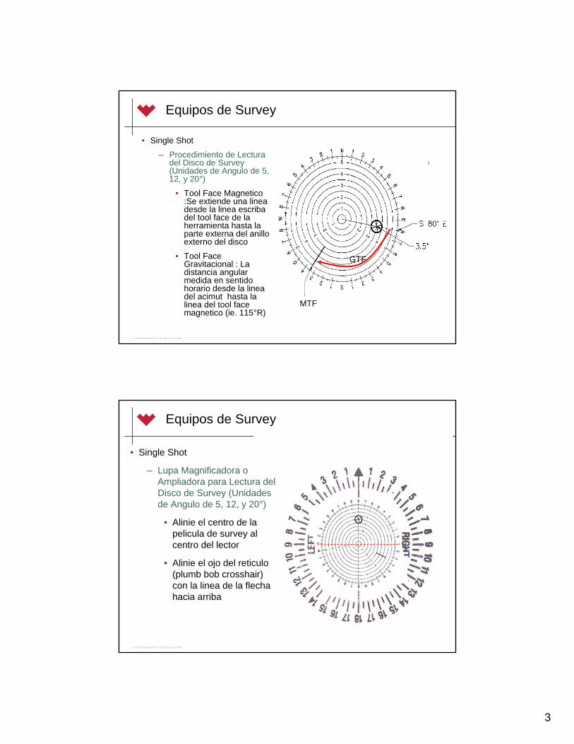
3
© 2006 Weatherford. All rights reserved.
Equipos de Survey
• Single Shot
– Procedimiento de Lecturadel Disco de Survey (Unidades de Angulo de 5, 12, y 20°)
• Tool Face Magnetico:Se extiende una lineadesde la linea escribadel tool face de la herramienta hasta la parte externa del anilloexterno del disco
• Tool Face Gravitacional : La distancia angular medida en sentidohorario desde la lineadel acimut hasta la linea del tool face magnetico (ie. 115°R)
MTF
GTF
© 2006 Weatherford. All rights reserved.
Equipos de Survey
• Single Shot
– Lupa Magnificadora o Ampliadora para Lectura del Disco de Survey (Unidadesde Angulo de 5, 12, y 20°)
• Alinie el centro de la pelicula de survey al centro del lector
• Alinie el ojo del reticulo(plumb bob crosshair) con la linea de la flechahacia arriba

4
© 2006 Weatherford. All rights reserved.
Equipos de Survey
• Single Shot
– Lupa Magnificadora o Ampliadora para Lecturadel Disco de Survey (Unidades de Angulo de 5, 12, y 20°)
• Acimut: Lea directamente de la interseccion del anilloexterno del disco de survey con la linea de la flecha (ie. S80E)
• Inclinacion: Cuente la posicion del numero de anillos desde el centrohasta el ojo del reticulo( plumb bob cross-hairs) del disco (ie. 3.5°)
© 2006 Weatherford. All rights reserved.
Equipos de Survey
• Single Shot
– Lupa Magnificadora o Ampliadora paraLectura del Disco de Survey (Unidades de Angulo de 5, 12, y 20°)
• TF Gravitacional : Extienda un lineadesde el centro del disco a traves de la marca del TF herramienta hasta la escala externa del lector. El TF Right/Left estaetiquetado en el lector (ie. 115°R)

5
© 2006 Weatherford. All rights reserved.
Equipos de Survey
• Single Shot
– Lupa Magnificadora o Ampliadora paraLectura del Disco de Survey (Unidades de Angulo de 5, 12, y 20°)
• TF Magnetico : Alinie la lineaescriba o marca del TF del disco de survey con la lineade la flecha del lector. El MTF es la interseccion de la linea de la flechacon la escal externadel disco de survey (ie. S35W)
© 2006 Weatherford. All rights reserved.
Equipos de Survey
• Single Shot
– Procedimiento de Lectura del Disco de Survey (Unidad de Angulo de 90°)
• Acimut: Leer desdela interseccion de la linea de direccion hasta el gimbal (ie. N27E)

6
© 2006 Weatherford. All rights reserved.
Equipos de Survey
• Single Shot
– Procedimiento de Lecturadel Disco de Survey (Unidad de Angulo de 90°)
• Inclinacion: Leer desdela interseccion de la linea horizontal con la escala numerica y vernier. La escalanumerica se muestra en incrementos de 10° (ie. 31°)
© 2006 Weatherford. All rights reserved.
Equipos de Survey
• Single Shot
– Procedimiento de Lecturadel Disco de Survey (Unidad de Angulo de 90°)
• Tool Face Magnetico : La lectura del acimutmas el angulo en grados desde la lineadel acimut en sentidohorario hasta la lineaescriba del TF (ie. N27E + 100° = S53E or 127°)
MTF = AZI + Arc

7
© 2006 Weatherford. All rights reserved.
Equipos de Survey
• Single Shot
– Procedimiento de Lecturadel Disco de Survey (Unidad de Angulo de 90°)
• Tool Face Gravitacional : El angulo desde la lineadel acimut hasta la linea escriba del tool face scribe en sentidohorario (solo el arco, esdecir100R)
GTF = Arc
© 2006 Weatherford. All rights reserved.
Equipos de Survey
• Single Shot
– Procedimiento de Lecturadel Disco de Survey (Unidad de Angulo de 90°) con el lector
• Tool Face Gravitacional : Centralice el disco de survey con el lector, la linea del acimutalineada con el la flecha hacia arriba. Leer el GTF en la interseccion de la lineamarca escriba del TF con la escala del lector externo (ie. 98R).

8
© 2006 Weatherford. All rights reserved.
Equipos de Survey
• Single Shot
– Notas Practicas :
• Todos los tool faces magenticos y los acimuts producidos o leidos de un disco de single shot esta SINCORREGIR por declinacion y convergencia
– Los surveys deben ser manualmente corregidos antes de entrarlos en un programa de surveys
• Cada fabricante o manufacturador de kits de single shot (ie. Humphries, Bob Fournet, MAC, etc.) producen discos de survey que se leen diferentes
– Es importante leer el manual de instrucciones antes de leer los discos de survey
• Los tool faces estan solo disponibles en el punto de survey; la orientacion o steering del pozo debe ser hecha al colocar un TF de orientacion estimandoel torque reactivo en cada slide y al monitorear el ajuste del motor (TF) manualmente en la mesa rotaria
• No asuma que el Perforador del equipo, El Tool Pusher, o el Company Man han leido los surveys del hoyo anterior o en el tie on correctamente
– Siempre trate de obtener los discos de los surveys originales y confirme los valores de los surveys; corrija si es necesario, llame a su coordinador siempre
© 2006 Weatherford. All rights reserved.
Equipos de Survey
• Single Shot
– Notas Practicas :
• Desconfie de los surveys queestan cerca o por ecnima de los limites de la unidad de angulo(ie. 5° unidad de angulo con survey de INC = or >5°)
– Si el angulo del hoyo excede el rango de medicion de la unidad, el reticulo puede solo indicar el valor maximo como se muestraen la escala de inclinacion(medicion mecanica) de la figura anexa
– Esto lo llevara a una incorrectoscalculos de la posicion del hoyo
– Es necesario en este casoretomar el survey del pozo en ese punto y recomputar la posicion


1
© 2007 Weatherford. All rights reserved.
Directional Drilling ITorque Reactivo
Revision 2
© 2007 Weatherford. All rights reserved.
Torque/Esfuerzo Reactivo
• La 3ra Ley del Movimiento de Sir Isaac Newton
– “Para cada accion, hay una igualy opuesta reaccion.”

2
© 2007 Weatherford. All rights reserved.
Torque Reactivo
• Un motor de fondo accionado por flujo de lodo hace girar la mecha en sentido horario(a mano derecha)
• Entonces, el cuerpo de este motor debetornarse en sentido contrario al horario (a la mano izquierda) para compensar
• La cara de la herramienta (tool face) se tornara y colocara entonces a la izquierdadel valor deseado
• La diferencia entre el tool face (en el fondo) y el tool face inicial (fuera del fondo) es el torque reactivo
• El torque reactivo es medido en grados
La mechagira a la derecha
El cuerpodel motor gira a la izquierda
© 2007 Weatherford. All rights reserved.
Torque Reactivo
• Cualquier cosa que incremente el torque/esfuerzo de salida del motor / torque aplicado aumentara el torque reactivo:
– Incremento en la taa de bombeo
– Un motor de Alto Torque
– Mecha con cortadores agresivos
– Incremento en el Peso sobre la Mecha / WOB
• La magnitud del torque reactivo podria ser estimada porla experiencia, regla del pulgar, diseño de BHA, etc. perogeneralmente esta sera determinada por las condicionesdel hoyo en el fondo en el taladro en el momento dado (ejemplo. 780o!)

3
© 2007 Weatherford. All rights reserved.
RFD
G
Torque Reactivo
• Ejemplo:
– El tool face actual es(fuera-fondo) de 30R
– El torque reactivo es 60o
– El tool face resultantecuando desliza sera de 30L porque el torque reactivo movera el tool face unos 60o en sentidocontrario al reloj (a la izquierda)
30R
RFD
G
Fuera -Fondo
En Fondo
30L30R
60o
© 2007 Weatherford. All rights reserved.
RFD
G
Torque Reactivo
• Ejemplo:
– Entonces, si se requiere de deslizar en puro high side, la mesa debe ser girada paraorientarla apropiadamenteantes de tocar el fondo paracompensar por el torque reactivo
– En este ejemplo, la mesa se debe tornar en 30o a la derechapara compensar por los 60 grados de torque reactivo y entonces lograr que el tool face se oriente en HS cuandoalcance el fondo nuevamente
30R
RFD
G
Fuera-Fondo
En Fondo
HS
60R60o
60R30o

4
© 2007 Weatherford. All rights reserved.
Torque Reactivo
• Consideraciones Practicas
– 1. Ajuste el tool face con el WOB
• Si el tool face cuando desliza esta ligeramentedesfasado del valor desiado, o la orientacion de la mesa debe ser ajustada o el WOB debe ser cambiado para compensar
• Usualmente para pequeños ajustes, cambios en el WOB es mas facil en taladros equipados con perforador automatico
– Si el WOB es aumentado, el torque reactivo aumentara, y el TF se moverá a la IZQUIERDA
– Si el WOB es disminuido, el torque reactivo también lo hará, y el TF se moverá a la DERECHA
© 2007 Weatherford. All rights reserved.
Torque Reactivo
• Consideraciones Practicas
– 2. Ajustando el tool face con la Mesa Rotaria
• Si la mesa debe ser movida, lo mejor es girar la mesda a la derecha cuando es posible paraeliminar cualquier posibilidad de un desenrosquede una conexion de tuberia

5
© 2007 Weatherford. All rights reserved.
Torque Reactivo
• Ejercicios de Muestra
Giro de la MesaTF DeseadoTorque Reactivo
(cuando tocafondo)
TF Fuera-Fondo
0HS120120 R
210 R60 R10050 L
25 L (335 R)45 L8060 R
1
© 2007 Weatherford. All rights reserved.
Directional Drilling IInstrumentos de Medicion Dimensionales
Revision 1
© 2007 Weatherford. All rights reserved.
Instrumentos de Medicion Dimensionales
• Todas las herramientas de perforacion direccional son medidaspara generar un diagrama dimensional (de pesca / fishing)
• El esquema dimensional de la herramienta, o el diagrama de Pesca(Fishing Diagram) es un dibujo/esquema de las dimensiones fisicasde los componentes de un BHA
• Este Dibujo/Esquema/Diagrama de pesca es usado en caso de quelas herramientas se atoren en el hoyo o hayan quedado alli y se requiere su extraccion (pesca) por un Fisherman
• La precision del Esquema Dimensional o Diagrama de Pesca escritica; errores aqui pueden conducir a un tiempo excesivo usadopara tratar de pescar una sarta o componentes de esta perdidos en el hoyo debido a una inapropiada seleccion de la herramienta de pesca (pescante o overshot)

2
© 2007 Weatherford. All rights reserved.
Instrumentos de Medicion Dimensionales
• Requerido Equipamiento
– Calipers (calibradores) de diametro interno (ID)
– Calipers (calibradores) de diametro externo (OD)
– Cinta Métrica de 12’ (3m)
– Cinta Métrica de 100’ (30 m)
© 2007 Weatherford. All rights reserved.
Measuring Tools
• Calipers de diametro interno (ID)
– Usado para medir el diametrointerno (abertura interna) de los tubulares
– Por convencion, la aberturaes medida por el lado de dentro del PIN de un collar
– Para medir la abertura, inserte the el caliper dentrodel pin, y expanda sus partastanto como posible
– Retire el caliper y lea estamedida sobre la cinta metrica

3
© 2007 Weatherford. All rights reserved.
Instrumentos de Medicion Dimensionales
• Calipers diametro externo (OD)
– Usado para medir el diametroexterno de los tubulares
– Por convencion, cualquiercambio en el OD debe ser medido y registrado
– Para medir el OD, expanda laspatas del caliper alrededor del punto de medicion tanto comosea posible
– Comprima el caliper hasta quetoque las paredes del tubular en su punto mas ancho del diametro a medir
– Retire el caliper y lea estamedida sobre la cinta metrica
© 2007 Weatherford. All rights reserved.
Instrumentos de Medicion Dimensionales
• Cinta Metrica de 12’ (3m)
– Usada para medir el largo o londitud de los sustitutoscortos, los collares, y los calipers de ID/OD
– Metrico
• Graduaciones en mm y cm
– Estandar/Imperial
• Graduaciones en decimas de pie y pulgadas fraccionales
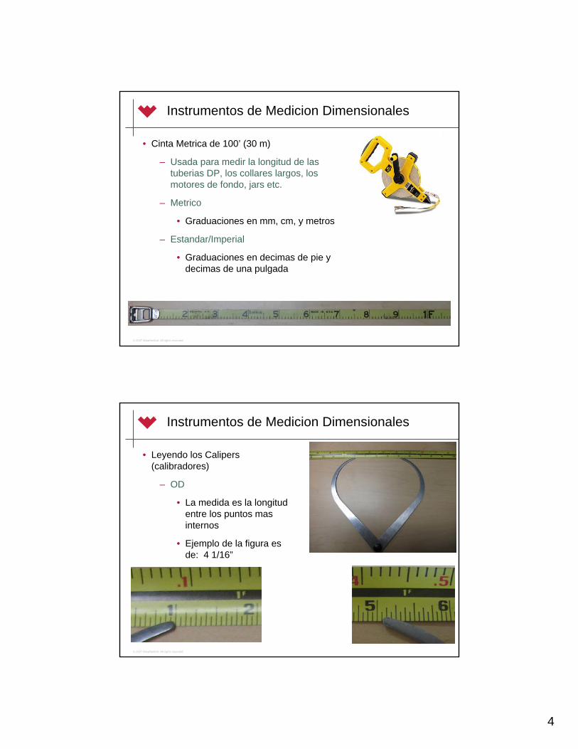
4
© 2007 Weatherford. All rights reserved.
Instrumentos de Medicion Dimensionales
• Cinta Metrica de 100’ (30 m)
– Usada para medir la longitud de lastuberias DP, los collares largos, los motores de fondo, jars etc.
– Metrico
• Graduaciones en mm, cm, y metros
– Estandar/Imperial
• Graduaciones en decimas de pie y decimas de una pulgada
© 2007 Weatherford. All rights reserved.
Instrumentos de Medicion Dimensionales
• Leyendo los Calipers (calibradores)
– OD
• La medida es la longitudentre los puntos masinternos
• Ejemplo de la figura esde: 4 1/16”

5
© 2007 Weatherford. All rights reserved.
Instrumentos de Medicion Dimensionales
• Leyendo los Calipers (calibradores)
– ID
• La medida es la longitudentre los puntos masexternos
• Ejemplo de la figura esde: 1 ¾”
© 2007 Weatherford. All rights reserved.
Instrumentos de Medicion Dimensionales
• Consideraciones Practicas
– 1. Unidad
• Metrica
– Largo en metros (ej. x.xx m)
– ID & OD en milimetros (ej. xx mm)
• Estandar
– Largo en decimas de pie (ej. x.xx ft)
– ID & OD en fracciones de pulgadas (ej. 4 ¾”)

6
© 2007 Weatherford. All rights reserved.
Instrumentos de Medicion Dimensionales
• Consideraciones Practicas
– 2. Longitud
• Todas las medidas de longitud deben referenciarse a puntosdesde el extremo inferior del tubular (desde el fondo del hoyo o hacia superficie) como punto comun referencial
• Items o puntos comunes para medir de longitud
– Juntas de Tubulares
– Largo de los Estabilizadores
– Cambios en los OD (diametros externos0
• NO incluya el largo del pin como parte de la medida de los puntos referenciales
© 2007 Weatherford. All rights reserved.
Instrumentos de Medicion Dimensionales
• Consideraciones Practicas
– 2. Longitud
• Siempe incluya el largo total en el diagrama

7
© 2007 Weatherford. All rights reserved.
Instrumentos de Medicion Dimensionales
• Consideraciones Practicas
– 3. Cuello de Pesca (Fishing Neck)
• Si el cuello de pesca(fishing neck) es de diferente ID al que el tubular tiene, el ID/abertura del cuello de pesca debe ser medidopara los casos en que la herramienta necesita ser extraida a traves de la restriccion
© 2007 Weatherford. All rights reserved.
Instrumentos de Medicion Dimensionales
• Consideraciones Practicas
• 3. Cuello de Pesca/Fishing Neck
• Nota: Para los tubularesque tienen cambios de OD (ej. Flex monels), la parte superior (tope) puede ser considerada como el cuello de pesca (fishing neck)
Fish Neck

8
© 2007 Weatherford. All rights reserved.
Instrumentos de Medicion Dimensionales
• Consideraciones Practicas
– 4. Jars (Martillos) y Otras Herramientas
• Los Martillos Tipicos (y algunas veces los Hevi-wate) tienen un ID o abertura mas pequeña que la tuberia de perforacion y los collares que hay en el BHA
• Siempre asegurese de medir la abertura de los martillos y cualquier otra herramienta miscelaneaque pudiera tener una abertura inusualmente maspequeña
© 2007 Weatherford. All rights reserved.
Instrumentos de Medicion Dimensionales
• Consideraciones Practicas
– 5. Estabilizadores
• El diametro externo (OD) de los Estabilizadores es siempremedido con un calibrador (caliper) de 3-puntos o con un anillo calibrador
• En aplicaciones de campo, los anillos calibradores son los mas comunmente usados
• Los anillos calibradores de diferentes dimensiones son pasados sobre el cuerpo del estabilizador
• El anillo calibrador mas pequeno que pase sobre el cuerpodel estabilizador indicara cual es diametro externo de este

9
© 2007 Weatherford. All rights reserved.
Instrumentos de Medicion Dimensionales
• Consideraciones Practicas
– 6. Numeros Seriales
• Cualquier herramienta direccional debe tener un numero serial registrada en el esquema
• Esto es requerido cuando las herramientas son perdidas hoyo abajo (LIH) como prueba para la compañia operadora de que las herramientasfueron realmente empleadas
© 2007 Weatherford. All rights reserved.
Instrumentos de Medicion Dimensionales
• Consideraciones Practicas
– 7. Juntas de las Herramientas (Tool Joints)
• Cualquier tubular debe tener el tipo de junta / conexion (ej. 4 ½” IF) registrada en el esquema
• Siempre inspeccione la condicion de la conexionde las tuberias cuando sea posible

10
© 2007 Weatherford. All rights reserved.
Instrumentos de Medicion Dimensionales
• Consideraciones Practicas
– 8. Equipamiento del Taladro/Rig
• Si se usa la cinta metrica del taladro, aseguresede que esta no este dañada ó “reparada” en un modo que afecte la precision de las mediciones
• Ejemplo: Cuando las cintas metricas se quiebrano parten, es una practica comun en algunostaladros de reparar las cintas partidas al empatarlas con grapas. Esto resulta en unamedida de la tuberia que es mayor que la real!
© 2007 Weatherford. All rights reserved.
Instrumentos de Medicion Dimensionales
• Consideraciones Practicas
– 9. Equipamiento extraño a la compañia
• Generalmente, se aconseja nunca medir unaherramienta que no sea propiedad de la companiaó que no haya sido rentado por la compania(herramientas del taladro = son responsabilidaddel taladro)
• Sin embargo, aun podria ser necesario chequeara cierta herramientas ajenas (ej. Jars & Herramientas Especiales para el trabajodireccional) si es que ellas pudieran impactardirectamente en el trabajo

140 – Directional Drilling I – Hoja de Trabajo Dimensiones y Calibre de Herramienta
Revision 1
NOMBRE:
STAB OD: __________

3 – Drilling a Directional Well Procedure.doc
140 – Directional Drilling I – Procedimiento de Perforación Direccional de Pozos Revision 0 Nota: Este procedimiento responde sólo a la tasa de construcción exigida (BURR) para alcanzar el blanco (en un pozo mono-dimensional direccional sencillo). Un procedimiento diferente debe seguirse para un pozo direccional que requiere determinaciones exactas de tasas de construccion y giro. 0. Verifique la propuesta, blancos, la elevación del KB. Entre el punto de amarre en Wellz y en la hoja de slide. 1. Anule la extrapolación anterior a la mecha, si es necesario. Escriba los nuevos surveys en la hoja de slide y en Wellz. 2. Calcule el slide visto, el rendimiento (BUR output) del motor, y la inclinación a la mecha en la hoja de slide.
a. Slide visto - la cantidad total de slide presente entre la estación del survey anterior (Previous SS) y la estación del survey actual (Current SS) como se determina en el lado derecho de la hoja de slide b. Motor BUR (grados por metro o pie) = (INCCurrent SS - INCPreviousSS) Slide total visto Motor BUR= INC_____
Slide total visto c. La Inclinación a la mecha (INC @ mecha) = INC de la Estación de Survey Corriente (actual) + (Slide Total desde la Estación Survey Actual a la mecha) x (BUR del Motor)
INC @ LA MECHA = INC + (Slide hasta la mecha) x (BUR del motor)
3. Escriba la extrapolación a la mecha como un survey en Wellz usando la INC @ a la Mecha calculada en (2). Ponga el acimut igual que el acimut del survey anterior. 4. Determine la tasa BUR Requerida (BURR) con la funcion de Proyeccion de Línea Recta de Wellz. 5. Use las funciones de Gráficos en “Plan and Section View” en Wellz para observar el progreso y posición del pozo relativo a la propuesta. Verifique las observaciones con los valores del BURR calculados en (4). 6. Determine si el slide requerido (BURRCalculated > BURRProposed) 7. Calcule la Longitud del Slide requerido y el Tool Face de la Herramienta.
a. La longitud del slide = (BURRCalculated / BUR del motor) * (longitud del sencillo o pareja)
b. El tool face de la herramienta - se determina por el valor en la columna de Turn Rate de la tabla de Constant Dog Leg Projections en Wellz
i. TR negativo = requiere GTF este a la izquierda del lado alto HS (gira a la izquierda)
ii. TR positivo = requiere GTF este a la derecha del lado alto HS (giro a la derecha)
8. Determinar si se requiere una acción correctiva adicional comparando los valores contenidos en la tabla de Straight Line Projections en Wellz o si la selección del objetivo designado debe cambiarse 9. Repita los pasos (1) a hasta (8) hasta que alcance la TD

COMO CALCULAR UN SLIDE SHEET Uno de los herramientas más importantes de un perforador direccional es la hoja de slide sheet. La hoja de slide sheet proporciona un registro escrito de toda la orientación del agujero en fondo. También permite a el perforador direccional poder proyectar con precisión a la mecha a través de los cálculos matemáticos. La hoja de slide también permite a otros perforar los futuros pozos según lo que se hizo y determinar el rendimiento de motor para el pozo dado. Lo siguiente es una explicación de cómo la hoja de slide trabaja, así como lo que se registra en esta y las fórmulas que se requieren para hacer los cálculos. Cada paso completando la hoja de slide se describirá y se etiquetará en gran detalle. Toda la información para el pozo se alista debajo. En cada paso, las filas, columnas y céldas se han identificado para ayudar en las descripciones. Cada célda en la hoja de slide será identificada primero por el número de la fila seguido por el número de la columna. La Célda 1D como el ejemplo representa la casilla en la primera fila bajo la columna D. Como ayuda se describe cómo la hoja de slide se llena, cada fila se discutirá en detalle por completo y se describirá en orden secuencial. La hoja de slide usada en este ejemplo es igual a la que que está impresa en el Programa First. La única diferencia entre las dos es que una columna se cambia. En la versión de la hoja de slide del programa First, una columna está allí para la configuración del motor de fondo. Ya que la configuración no se puede cambiar abajo en el agujero, entonces esta columna no se usa. Para los propósitos de la instruccion, se grabará la inclinación a la mecha por el momento en esta columna. Lo siguiente es una descripción rápida de cada columna:
A B C D E F G H I J K L M N
Measured Depth
Survey Depth Inc Az
Mts slideseen
BUR /m
BUR /30m
Inc @ Bit TF From To Total
1 9.53 920.50 904.50 .23 160.33 - - - -
• Columna A: La longitud de cada cañería DP/ o heviwate a ser usada. • Columna B: La Profundidad a la que se encuentra la mecha. Incluye todas las
herramientas y cañerías. • Columna C: La profundidad a la que el survey se toma (generalmente 15. 19
metros detrás de la mecha. • Columna D: La inclinación que se graba a la profundidad del Survey, no la de la
mecha. • Columna E: El acimut que se graba a la profundidad del survey, de nuevo, no la
profundidad de la mecha. • Columna F: El total de cuántos metros/pies de slide que se han visto/hecho entre
el último survey y el Survey actual
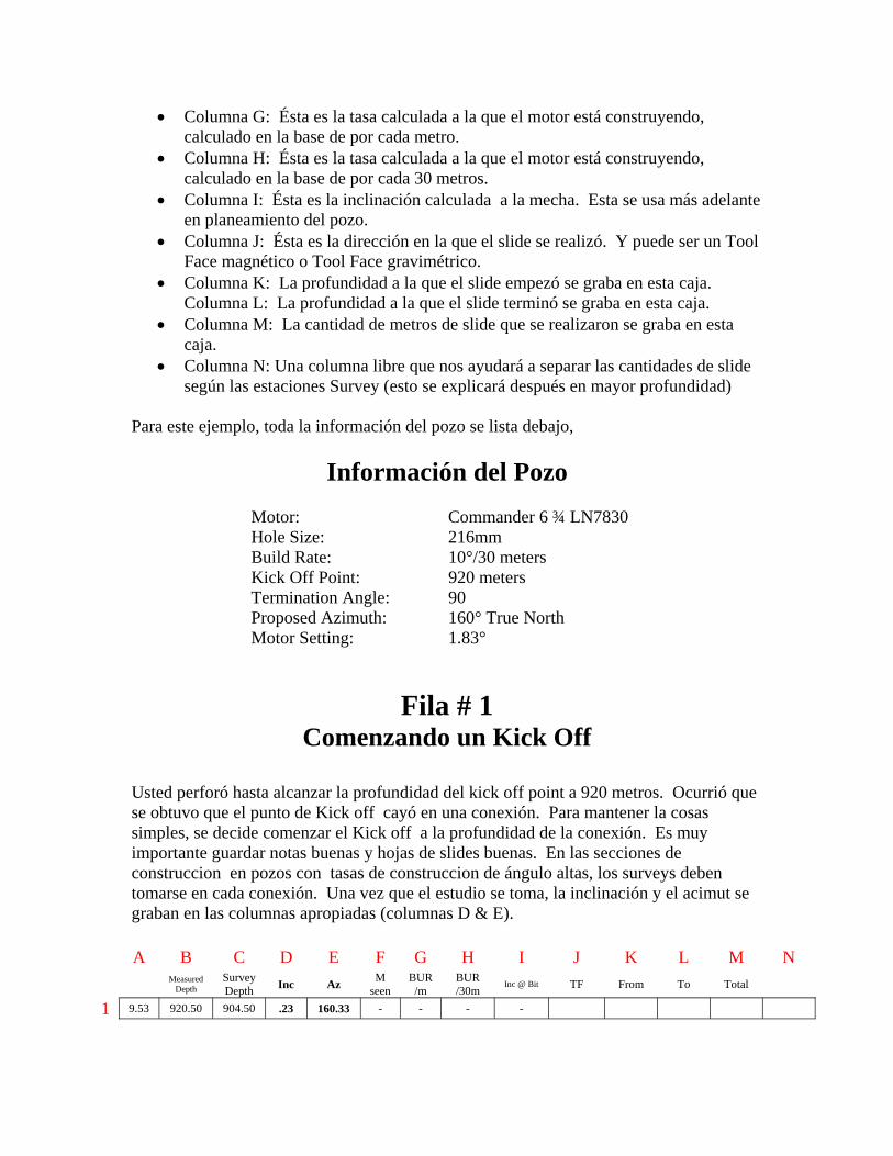
• Columna G: Ésta es la tasa calculada a la que el motor está construyendo, calculado en la base de por cada metro.
• Columna H: Ésta es la tasa calculada a la que el motor está construyendo, calculado en la base de por cada 30 metros.
• Columna I: Ésta es la inclinación calculada a la mecha. Esta se usa más adelante en planeamiento del pozo.
• Columna J: Ésta es la dirección en la que el slide se realizó. Y puede ser un Tool Face magnético o Tool Face gravimétrico.
• Columna K: La profundidad a la que el slide empezó se graba en esta caja. Columna L: La profundidad a la que el slide terminó se graba en esta caja.
• Columna M: La cantidad de metros de slide que se realizaron se graba en esta caja.
• Columna N: Una columna libre que nos ayudará a separar las cantidades de slide según las estaciones Survey (esto se explicará después en mayor profundidad)
Para este ejemplo, toda la información del pozo se lista debajo,
Información del Pozo
Motor: Commander 6 ¾ LN7830 Hole Size: 216mm Build Rate: 10°/30 meters Kick Off Point: 920 meters Termination Angle: 90 Proposed Azimuth: 160° True North Motor Setting: 1.83°
Fila # 1 Comenzando un Kick Off
Usted perforó hasta alcanzar la profundidad del kick off point a 920 metros. Ocurrió que se obtuvo que el punto de Kick off cayó en una conexión. Para mantener la cosas simples, se decide comenzar el Kick off a la profundidad de la conexión. Es muy importante guardar notas buenas y hojas de slides buenas. En las secciones de construccion en pozos con tasas de construccion de ángulo altas, los surveys deben tomarse en cada conexión. Una vez que el estudio se toma, la inclinación y el acimut se graban en las columnas apropiadas (columnas D & E).
A B C D E F G H I J K L M N Measured
Depth Survey Depth Inc Az M
seen BUR
/m BUR /30m
Inc @ Bit TF From To Total
1 9.53 920.50 904.50 .23 160.33 - - - -

Paso # 1: Determinar cuanto slide hacer al punto de kick off Al momento en que las herramientas simplemente se han armado en superficie, no hay ninguna manera de determinar lo que el motor producirá para las patas de perro (DL). En su lugar, en el libro de especificaciones del los motores solo le brindara una idea. En la página , del motor le dirá qué tipo de dogleg (BUR estimado) el motor producirá a las diferentes ajustes/ configuraciones de este. El grafico aqui desplegado es de un motor 6 ¾" LN7830. El tamaño del agujero que estamos taladrando es un 8 ½", con un ajuste de 1.83 grados. Mirando el grafico, se estima que el motor debe producir 12° / 30 metros. La tasa de construccion en la propuesta para este pozo es de 10° / 30 meters. La formula para calcular cuanto slide se requiere es:
Or La respuesta de 7.94 metros representa la cantidad slide que tendrá que realizar en un sencillo DP (single) para lograr una tasa de construcción (BUR) de 10 grados en el pozo. Redondeando, decidimos deslizar 8 metros en la dirección propuesta (23 magnético, célda 1J). Se grabó la longitud del slide en la célda 1M.
A B C D E F G H I J K L M N Measured
Depth Survey Depth Inc Az M
seen BUR
/m BUR /30m
Inc @ Bit TF From To Total
1 9.53 920.50 904.50 .23 160.33 - - - - 23 Mag 8
Well bore Diameter 216mm 222mm 251mm
Adjustable Setting
Bend Angle
8.5 in 8.75 in 9.875 in B .39 2 1 - C .78 4 4 1 D 1.15 7 7 4 E 1.5 10 9 6 F 1.83 12 11 9 G 2.12 14 14 11 H 2.38 16 15 13 I 2.6 18 17 14 J 2.77 19 18 16 K 2.9 20 19 16 L 2.97 20 20 17 M 3 21 20 17
Build Rate Requerido
Motor Output
X Longitud de un Single
10 12 X 9.53 (Cell 1A) = 7.94
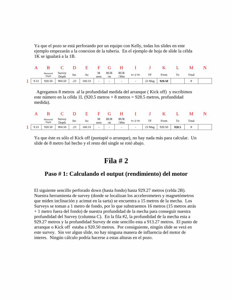
Ya que el pozo se está perforando por un equipo con Kelly, todas los slides en este ejemplo empezarán a la conexion de la tuberia. En el ejemplo de hoja de slide la célda 1K se igualará a la 1B.
A B C D E F G H I J K L M N Measured
Depth Survey Depth Inc Az M
seen BUR
/m BUR /30m
Inc @ Bit TF From To Total
1 9.53 920.50 904.50 .23 160.33 - - - - 23 Mag 920.50 8
Agregamos 8 metros al la profundidad medida del arranque ( Kick off) y escribimos este número en la célda 1L (920.5 metros + 8 metros = 928.5 metros, profundidad medida).
A B C D E F G H I J K L M N Measured
Depth Survey Depth Inc Az M
seen BUR
/m BUR /30m
Inc @ Bit TF From To Total
1 9.53 920.50 904.50 .23 160.33 - - - - 23 Mag 920.50 928.5 8
Ya que éste es sólo el Kick off (puntapié o arranque), no hay nada más para calcular. Un slide de 8 metro fué hecho y el resto del single se rotó abajo.
Fila # 2
Paso # 1: Calculando el output (rendimiento) del motor
El siguiente sencillo perforado down (hasta fondo) hasta 929.27 metros (celda 2B). Nuestra herramienta de survey (donde se localizan los accelerometers y magnetómetros que miden inclinación y acimut en la sarta) se encuentra a 15 metros de la mecha. Los Surveys se toman a 1 metro de fondo, por lo que substraemos 16 metros (15 metros atrás + 1 metro fuera del fondo) de nuestra profundidad de la mecha para conseguir nuestra profundidad del Survey (columna C). En la fila #2, la profundidad de la mecha esta a 929.27 metros y la profundidad Survey de este sencillo esta a 913.27 metros. El punto de arranque o Kick off estaba a 920.50 metros. Por consiguiente, ningún slide se verá en este survey. Sin ver algun slide, no hay ninguna manera de influencia del motor de interes. Ningún cálculo podría hacerse a estas alturas en el pozo.

Paso # 2: Determinando cuanto se requiere de slide Como se menciona en el paso #1, no hay modo alguno de calcular la influencia del motor de interes a estas alturas. Sin poder saber la tasa de construccion BUR (pata de perro) que el motor producirá, deben usarse los valores del libro. El cálculo que se usa para determinar cuánto deslizar es igual que en la Fila #1. De nuevo, redondeando, decidimos deslizar 8 metros. El slide se graba igual que la fila número 1 y en la dirección originalmente propuesta. De nuevo, en este ejemplo el slide empieza siempre al principio del sencillo. Por consiguiente, 2K es igual a 2B. Debido a que estamos deslizando 8 metros de nuevo, agregamos 8 metros al principio del slide para calcular el fin del slide (929.97 (célda 2K) + 8 (célda 2M) = 937.97 (célda 2L)
A B C D E F G H I J K L M N Measured
Depth Survey Depth Inc Az M
seen BUR
/m BUR /30m
Inc @ Bit TF From To Total
1 9.53 920.50 904.50 .23 160.33 - - - - 23 Mag 920.50 928.5 8
2 9.47 929.97 913.97 .43 160.67 - - - - 23 Mag 929.97 937.97 8
Fila # 3
Paso # 1: Calculando el slide visto
El próximo sencillo abajo es 939.48 metros (célda 3B) y la estación del estudio/survey es 923.48 metros (célula 3C). El survey se toma y se graban la inclinación y el acimut respectivamente en las celdas 3D y 3E. Desde que arrancamos el Kick off del pozo a 920.5 metros, sabemos que estaremos viendo solo 2.98 metros de slide. 923.48 (célda 3C) - 920.50 (célda 1K) = 2.98. Este número se entra en la célda 3F. El resto de la primer slide (de 923.48 a 928.5) se verá en el próximo survey. Para la facilidad de registrar y llevar la cuenta de cuánto slide se ha visto y cuánto se verá en el próximo survey, se escribirán 2.98 metros en la esquina superior a la mano izquierda de la celda 1N. El resto (8 (célda 1M) - 2.98 (célda 3F) = 5.02 ó los 928.5 (célda 1L) - 923.48 (célda 3C) = 5.02) se escribe en la esquina derecho al fondo de la celda1N.
10° 12° X 9.47 (Cell 2A) = 7.89

A B C D E F G H I J K L M N Measured
Depth Survey Depth Inc Az M
seen BUR
/m BUR /30m
Inc @ Bit TF From To Total
1 9.53 920.50 904.50 .23 160.33 - - - - 23 Mag 920.50 928.5 8 2.98 5.02
2 9.47 929.97 913.97 .43 160.67 - - - - 23 Mag 929.97 937.97 8
3 9.51 939.48 923.48 1.85 161.01 2.98
Paso # 2: Calculando el output (rendimiento) del motor El próximo paso en fila #3 es calcular la tasa de construcción. La tasa de construcción BUR nos dice simplemente cuan rápido el motor está construyendo. Esto se logra dividiendo el cambio en la inclinación por la cantidad de metros de slide que usted esta viendo en este sencillo. La fórmula para este cálculo es:
Inc Survey Actual – Inc Anterior survey Metros de Slide Vistos
= Build up Rate Por Metro
Substituyendo celda y numeros, la formula se vera como: La respuesta a esta ecuacion se mete en la celda 3G. Para calcular el build up rate para 30 metros, justamente se multiplica este numero por 30.
Or
.48° / metros x 30 metros = 14.4° / 30m El BUR calculado se mete en la celda 3H.
A B C D E F G H I J K L M N Measured
Depth Survey Depth Inc Az M
seen BUR
/m BUR /30m
Inc @ Bit TF From To Total
1 9.53 920.50 904.50 .23 160.33 - - - - 23 Mag 920.50 928.5 8 2.98 5.02
2 9.47 929.97 913.97 .43 160.67 - - - - 23 Mag 929.97 937.97 8
3 9.51 939.48 923.48 1.85 161.01 2.98 .48 14.4
3D – 2D 1.85° - .43° 3F = 3G or 2.98 m = .48°/m
Build up rate por metro x 30 metros = build up rate por 30 metros

Paso # 3: Calculando la inclinación a la mecha Ahora que tenemos el motor output calculado, es hora de calcular cual es la inclinacion a la mecha. ¡TODAS LAS PROYECCIONES FUTURAS TIENEN QUE HACERSE DESDE LA MECHA! La falla de no hacerlos asi podría producir una colision del pozo o perdida del objetivo Si un motor no está produciendo bastante BUR, se descubre fácilmente y se aumenta entonces la proporción/longitud del slide que compensara por las tasas bajas de construccion. Si se está perforando desde la estación del survey, para el momento cuando vea las bajas tasas de construccion, la inclinación a la mecha exigiría de medidas drásticas para poder compensar y salvar el pozo. En el Paso #2 pudimos calcular el BUR basado en la cantidad de influencia que los 2.98 metros de slide tenían sobre nuestra inclinación. Ahora vamos a calcular que valor tendrá la inclinación a la mecha al usar la misma cantidad de influencia. Mirando la célda 1N sabemos que había 5.02 metros de slide que no hemos visto todavía. Además de eso, sabemos que no hemos visto aún los 8 metros de slide del segundo sencillo (célda 2M). Los metros totales de slide no vistos todavía serían los 5.02 (célda 1N) + 8 (célda 2M) = 13.02 metros de slide no vistos todavía. Sabemos que el BUR para este sencillo es de (.48° / metro (célda 3G)). Todo lo que tenemos que hacer es multiplicar y conseguiremos:
Metros de slide entre la estacion de survey y la
mecha. x
Rendimiento del Motor en °/metro
=
Grados de inclinacion entre la estacion de survey y
la mecha.
Or
13.02 metros x .48°/metro = 6.25° Calculamos ahora que tenemos 6.25° de inclinación entre nuestra última estación de Survey y la mecha. Sabiendo esto, es fácil de calcular ahora la inclinación a la mecha. Todo lo que tenemos que hacer es sumar este número a la inclinación actual.
Grados entre la estación de survey y la mecha + inclinación del
ultimo survey = Inclinación a la mecha
Or
6.25° + 1.85° = 8.10°

Una vez que este número es calculado, es registra en la hoja de slide y se entra en el programa de registros como una extrapolación a la mecha. En la hoja de slide, se entra en la célda 3I .
A B C D E F G H I J K L M N Measured
Depth Survey Depth Inc Az M
seen BUR
/m BUR /30m
Inc @ Bit TF From To Total
1 9.53 920.50 904.50 .23 160.33 - - - - 23 Mag 920.50 928.5 8 2.98 5.02
2 9.47 929.97 913.97 .43 160.67 - - - - 23 Mag 929.97 937.97 8
3 9.51 939.48 923.48 1.85 161.01 2.98 .48 14.4 8.10
Paso # 4: Determinando cuanto se requiere de slide
Determinando cuántos metros para deslizar es lo mismo en todas las filas. Si está buscando las fórmulas, mire atrás a la Fila #1, Paso #1. La única diferencia es a estas alturas que estamos empezando a ver cuán rápido el motor realmente está construyendo. La misma fórmula se usa como en las filas 1 y 2, pero esta vez estaremos influenciados por el rendimiento del motor calculado en la fila #3. Usando un programa de survey o cálculos de mano, se calcula lo que se requiere para BUR para dar en el blanco / target (el calculo de tasa de construcción para dar en el blanco se cubre en el programa de planificación de pozos y no el de calculo de una hoja de slide). Después de que la planificación del pozo está completa, el BUR de 9.90°/30 se requiere para alcanzar el blanco/ target. El rendimiento del motor a estas alturas en el tiempo es de 14.4°/30 metros (calculado en fila 3). Sin embargo, éste es el primer slide en el pozo y a veces podría en este caso ser mayor el rendimiento del motor que el normal. Por esta razón en lugar de usar un 14.4 para el rendimiento del motor, vamos a usar 13°/30. Esto esta basado en un promedio general entre el valor del libro y el rendimiento de motor real (12°/30 valor según el libro y el rendimiento real del motor de 14.4°/30). La cantidad que vamos a deslizar es: Deslizando en el lado de la cautela, decidimos delizar 7.5 metros en este sencillo. Como se describe antes, la información del slide se introduce apropiadamente
A B C D E F G H I J K L M N Measured
Depth Survey Depth Inc Az M
seen BUR
/m BUR /30m
Inc @ Bit TF From To Total
1 9.53 920.50 904.50 .23 160.33 - - - - 23 Mag 920.50 928.5 8 2.98 5.02
2 9.47 929.97 913.97 .43 160.67 - - - - 23 Mag 929.97 937.97 8
3 9.51 939.48 923.48 1.85 161.01 2.98 .48 14.4 8.10 23 Mag 939.48 946.98 7.5
9.9° 13° X 9.51 (Celda 3A) = 7.24 metros

Fila # 4 Cada fila que se completa será de la misma manera. Los pasos para calcular cuánto deslizarara siempre serán los mismos: 1. Calcular cuánta slide está viendo. 2. Calcular el rendimiento del motor (pata de perro o BUR) 3. Proyectar a la mecha. 4. Usar un programa de cálculo de survey, determinar el BUR requerido para pegar en el blanco (no esta cubierto en el uso de la hoja de slide). 5. Calcular cuánto deslizar.
Paso # 1: Calcular cuanto slide se ha visto
Justo como hemos hecho en el pasado, la primera cosa que registramos es el survey que fue tomado en la estacion de survey. En la fila 4 el survey resulta de 4.92° de inclinación y de 160.21° azimuth.
A B C D E F G H I J K L M N Measured
Depth Survey Depth Inc Az M
seen BUR
/m BUR /30m
Inc @ Bit TF From To Total
1 9.53 920.50 904.50 .23 160.33 - - - - 23 Mag 920.50 928.5 8 2.98 5.02
2 9.47 929.97 913.97 .43 160.67 - - - - 23 Mag 929.97 937.97 8
3 9.51 939.48 923.48 1.85 161.01 2.98 .48 14.4 8.10 23 Mag 939.48 946.98 7.5
4 9.44 948.92 932.92 4.96 160.21
El paso uno es tomar el survey a la profundidad de 932.92 (celda 4C) y encontrar donde en la información de slide se encontrará esta profundidad. La profundidad actual esta localizada en el slide entre 929.97 y 937.97 (celda 2K y 2L). En este survey nosotros veremos desde 929.97 (el comienzo del slide) hasta 932.92 (profundidad del survey). Entonces podemos decir que veremos:
932.92 – 929.97 = 2.95 2.95 metros es cuantos metros de slide nosotros vamos a ver en este survey. De nuevo, nosotros escribiremos este numero en la parte esquina superior izquierda de la celda 2N.
A B C D E F G H I J K L M N Measured
Depth Survey Depth Inc Az M
seen BUR
/m BUR /30m
Inc @ Bit TF From To Total
1 9.53 920.50 904.50 .23 160.33 - - - - 23 Mag 920.50 928.5 8 2.98 5.02
2 9.47 929.97 913.97 .43 160.67 - - - - 23 Mag 929.97 937.97 8 2.95
3 9.51 939.48 923.48 1.85 161.01 2.98 .48 14.4 8.10 23 Mag 939.48 946.98 7.5
4 9.44 948.92 932.92 4.92 160.21

Manteniendo las cosas simples nosotros escribiremos el recordatorio del slide en la esquina baja derecha de esta celda (8 – 2.95 = 5.05 metros).
A B C D E F G H I J K L M N Measured
Depth Survey Depth Inc Az M
seen BUR
/m BUR /30m
Inc @ Bit TF From To Total
1 9.53 920.50 904.50 .23 160.33 - - - - 23 Mag 920.50 928.5 8 2.98 5.02
2 9.47 929.97 913.97 .43 160.67 - - - - 23 Mag 929.97 937.97 8 2.95 5.05
3 9.51 939.48 923.48 1.85 161.01 2.98 .48 14.4 8.10 23 Mag 939.48 946.98 7.5
4 9.44 948.92 932.92 4.92 160.21
Sabemos que nuestro survey verá los 2.95 metros que nosotros simplemente hemos acabado de calcular. Mirando la célda 1N, sabemos también que habían 5.02 metros que quedaron por ver del survey anterior. Para calcular cuántos metros de slide se ven en este survey, debemos sumar los dos números (5.02 + 2.95 = 7.97). El número que acabamos de calcular simplemente es la cantidad de slide total que vamos a ver en este sencillo deslizado. Y se graba en la célda 4F.
A B C D E F G H I J K L M N Measured
Depth Survey Depth Inc Az M
seen BUR
/m BUR /30m
Inc @ Bit TF From To Total
1 9.53 920.50 904.50 .23 160.33 - - - - 23 Mag 920.50 928.5 8 2.98 5.02
2 9.47 929.97 913.97 .43 160.67 - - - - 23 Mag 929.97 937.97 8 2.95 5.05
3 9.51 939.48 923.48 1.85 161.01 2.98 .48 14.4 8.10 23 Mag 939.48 946.98 7.5
4 9.44 948.92 932.92 4.92 160.21 7.97
Paso # 2: Calcular el rendimiento (output) del motor Este paso tambien sera el mismo a travez de la hoja entera de slide. En summario, tomaremos el cambio en la inclinacion y la dividimos por los metros deslizados. Una vez mas, este numero es escrito en la celda 4G
A B C D E F G H I J K L M N Measured
Depth Survey Depth Inc Az M
seen BUR
/m BUR /30m
Inc @ Bit TF From To Total
1 9.53 920.50 904.50 .23 160.33 - - - - 23 Mag 920.50 928.5 8 2.98 5.02
2 9.47 929.97 913.97 .43 160.67 - - - - 23 Mag 929.97 937.97 8 2.95 5.05
3 9.51 939.48 923.48 1.85 161.01 2.98 .48 14.4 8.10 23 Mag 939.48 946.98 7.5
4 9.44 948.92 932.92 4.92 160.21 7.97 .39
4D – 3D 4.92° - 1.85° 4F = 4G or 7.97 m = .39°/m

En orden para obtener el build rate en una escala de /30 metros, justo se multiplica .39°/meter por los 30 metros (.39 x 30 = 11.7°). Este numero se escribe en la hoja de slide sheet en la celda 4H.
A B C D E F G H I J K L M N Measured
Depth Survey Depth Inc Az M
seen BUR
/m BUR /30m
Inc @ Bit TF From To Total
1 9.53 920.50 904.50 .23 160.33 - - - - 23 Mag 920.50 928.5 8 2.98 5.02
2 9.47 929.97 913.97 .43 160.67 - - - - 23 Mag 929.97 937.97 8 2.95 5.05
3 9.51 939.48 923.48 1.85 161.01 2.98 .48 14.4 8.10 23 Mag 939.48 946.98 7.5
4 9.44 948.92 932.92 4.92 160.21 7.97 .39 11.7
Paso # 3: Calculando la inclinacion a la mecha En el Paso # 2, nosotros calculamos en la celda 2N que nosotros estamos viendo el tope de los 2.95 metros de slide en ese sencillo. Con esto en mente, nosotros sabemos que no estamos viendo el fondo de los 5.05 metros de slide. Nosotros tambien sabemos que no estamos viendo el ultimo slide (7.5 metros en la celda 3M). Para calcular cuanto slide tenemos por delante, tenemos justamente que adicionar a los dos en conjunto (5.05 + 7.5 = 12.55 meters). Esta cifra es cuantos metros de slide tenemos entre el ultimo survey y la mecha. Tambien sabemos cuán dificil el motor esta construyendo porque nosotros hemos estado calculandolo (filas G y H). He aqui la caja magica del directional driller. En lugar de usar el ultimo BUR de 11.7°/30 lo que heremos ahora es usar un average de lo que nostros pensamos que esta pasando hoyo abajo. Este sencillo produce 11.7°/30 de build rate, pero el sencillo anterior produjo 14.4°/30 de build rate. En este ejemplo, vamos a usar un average de los dos, pero pobdremos mas énfasis en el ultimo build rate. La razon para esto en este ejemplo es que en el primer survey solo son visto los primeros 2.98 metros de slide. El motor podría estar colocandose delante en el slide o podría influenciarse de otras maneras. El segundo Survey está viendo los 7.97 metros de slide. Hay más metros de slide para ver y esto hace que nuestros números entonces parezcan un poco más consistente que las pequeñas influencias y palmaditas. Al proyectar a la mecha en este ejemplo que vamos a usar una media de BUR de 12.5°/30 o .42° /meter. Sabiendo que tenemos 12.55 metros de slide delante de nosotros, y una media de BUR de .42° / metro, la matemática será como:
Metross de slide entre el survey station y la mecha. x
Rendimiento del Motor en °/metro
=
Grados de inclinacion entre el survey station y la
mecha.
Or
12.55 metros x .42°/metro = 5.27°

Calculamos ahora que tenemos 5.27° de inclinación entre nuestra última estación de survey y la mecha. Sabiendo esto, es fácil calcular la inclinación a la mecha. Todo lo que tenemos que hacer es sumar este número a la inclinación actual
Grados entre el survey station y la mecha + inclinación del
ultimo survey = Inclinación a la mecha
Or
Como con todos los pasos anteriores, la inclinación a la mecha se escribe en la hoja de slide en la celda 4I.
A B C D E F G H I J K L M N Measured
Depth Survey Depth Inc Az M
seen BUR
/m BUR /30m
Inc @ Bit TF From To Total
1 9.53 920.50 904.50 .23 160.33 - - - - 23 Mag 920.50 928.5 8 2.98 5.02
2 9.47 929.97 913.97 .43 160.67 - - - - 23 Mag 929.97 937.97 8 2.95 5.05
3 9.51 939.48 923.48 1.85 161.01 2.98 .48 14.4 8.10 23 Mag 939.48 946.98 7.5
4 9.44 948.92 932.92 4.92 160.21 7.97 .39 11.7 10.19
Paso # 4: Determinando cuanto deslizar
La inclinación a ala mecha se calcula y entra en su programa de calculo de Survey como una extrapolación. Esta extrapolación entonces se usa para calcular la tasa de construccion BUR exigida para dar en el blanco. En este ejemplo, el BUR requerido es 10.08°/30. Recordamos de proyectar a la mecha que el motor está produciendo un promedio de 12.5°/30. Usando los mismos cálculos como en las filas anteriores, concluimos:
5.27° + 4.92° = 10.19°
Build up Rate Requerido 10.08°/30
Motor Output X
Largo del
Sencillo =
Metros de Slide
Requeridos or
12.5°/30 X 9.50 = 7.66

En nuestro habito de redondear este tipo de informacion, decidimos deslizar 7.5 metros. Esta informacion se escribe en la hoja de slide en la celda M4
A B C D E F G H I J K L M N Measured
Depth Survey Depth Inc Az M
seen BUR
/m BUR /30m
Inc @ Bit TF From To Total
1 9.53 920.50 904.50 .23 160.33 - - - - 23 Mag 920.50 928.5 8 2.98 5.02
2 9.47 929.97 913.97 .43 160.67 - - - - 23 Mag 929.97 937.97 8 2.95 5.05
3 9.51 939.48 923.48 1.85 161.01 2.98 .48 14.4 8.10 23 Mag 939.48 946.98 7.5
4 9.44 948.92 932.92 4.92 160.21 7.97 .39 11.7 10.19 7.5
Recordamos que los slides en este ejemplo comienzan al comienzo del sencillo, entonces la informacion se escribe en: K4
A B C D E F G H I J K L M N Measured
Depth Survey Depth Inc Az M
seen BUR
/m BUR /30m
Inc @ Bit TF From To Total
1 9.53 920.50 904.50 .23 160.33 - - - - 23 Mag 920.50 928.5 8 2.98 5.02
2 9.47 929.97 913.97 .43 160.67 - - - - 23 Mag 929.97 937.97 8 2.95 5.05
3 9.51 939.48 923.48 1.85 161.01 2.98 .48 14.4 8.10 23 Mag 939.48 946.98 7.5
4 9.44 948.92 932.92 4.92 160.21 7.97 .39 11.7 10.19 948.92 7.5
Nosotros adicionamos el largo del sencillo donde arrancamos, y resulta en: (L4)
A B C D E F G H I J K L M N Measured
Depth Survey Depth Inc Az M
seen BUR
/m BUR /30m
Inc @ Bit TF From To Total
1 9.53 920.50 904.50 .23 160.33 - - - - 23 Mag 920.50 928.5 8 2.98 5.02
2 9.47 929.97 913.97 .43 160.67 - - - - 23 Mag 929.97 937.97 8 2.95 5.05
3 9.51 939.48 923.48 1.85 161.01 2.98 .48 14.4 8.10 23 Mag 939.48 946.98 7.5
4 9.44 948.92 932.92 4.92 160.21 7.97 .39 11.7 10.19 948.92 956.42 7.5
Porque la dirección propuesta es de 160° acimut y estamos encaminandonos directamente en esa dirección vamos a seguir deslizando en esa dirección. Sin embargo, en los dos herramientas la de pulso y la de EM, nuestro tool face va a cambiar de una TF magnético a un TF gravimétrico. Ahora en lugar de deslizar a una dirección relacionada al norte magnético, vamos a deslizar respecto a una dirección relacionada a la gravedad. Puesto que queremos mantenernos construyendo inclinación, vamos a deslizar con una cara de la herramienta alta (HSTF) (o directamente cara arriba). Si quisiéramos voltear el hoyo ligeramente a la derecho, podríamos deslizar con un TF de 20R (20 grados a la derecha).

Si quisiéramos girar el pozo ligeramente a la izquierda, podríamos deslizar con un TF de 20L (20 grados a la izquierda).Este TF de la herramienta se graba en la hoja de la slide.
A B C D E F G H I J K L M N Measured
Depth Survey Depth Inc Az M
seen BUR
/m BUR /30m
Inc @ Bit TF From To Total
1 9.53 920.50 904.50 .23 160.33 - - - - 23 Mag 920.50 928.5 8 2.98 5.02
2 9.47 929.97 913.97 .43 160.67 - - - 3.63 23 Mag 929.97 937.97 8 2.95 5.05
3 9.51 939.48 923.48 1.85 161.01 2.98 .48 14.4 8.10 23 Mag 939.48 946.98 7.5
4 9.44 948.92 932.92 4.92 160.21 7.97 .39 11.7 10.19 HS 948.92 956.42 7.5
Fila # 5 A este tiempo, para este punto debe poderse deducir la mayoría de los cálculos y podemos movernos bastante rápido a través de esta fila. El survey resulta como 7.84° de inclinación y un acimut de 159.88°. Estos números se escriben en la hoja de slide y los cálculos comienzan.
Paso # 1: Calculando el slide visto El survey a 942.42 metros cae entre el slide hecho desde 939.48 hasta 946.98 metros (celdas de 3K a 3L). 942.42 – 939.48 = 2.94. Este se escribe en la esquina superior izquierda de la celda 3N.
A B C D E F G H I J K L M N Measured
Depth Survey Depth Inc Az M
seen BUR
/m BUR /30m
Inc @ Bit TF From To Total
1 9.53 920.50 904.50 .23 160.33 - - - - 23 Mag 920.50 928.5 8 2.98 5.02
2 9.47 929.97 913.97 .43 160.67 - - - 3.63 23 Mag 929.97 937.97 8 2.95 5.05
3 9.51 939.48 923.48 1.85 161.01 2.98 .48 14.4 8.10 23 Mag 939.48 946.98 7.5 2.94
4 9.44 948.92 932.92 4.96 160.21 7.97 .39 11.7 10.19 HS 948.92 956.42 7.5
5 9.50 958.42 942.42 7.84 159.88
Estos 2.94 metros se sustraen del monto de slide de esta fila (7.5 metros), y se escriben en la esquina inferior derecha de la celda (7.5 – 2.94 = 4.56).

A B C D E F G H I J K L M N Measured
Depth Survey Depth Inc Az M
seen BUR
/m BUR /30m
Inc @ Bit TF From To Total
1 9.53 920.50 904.50 .23 160.33 - - - - 23 Mag 920.50 928.5 8 2.98 5.02
2 9.47 929.97 913.97 .43 160.67 - - - 3.63 23 Mag 929.97 937.97 8 2.95 5.05
3 9.51 939.48 923.48 1.85 161.01 2.98 .48 14.4 8.10 23 Mag 939.48 946.98 7.5 2.94 4.56
4 9.44 948.92 932.92 4.96 160.21 7.97 .39 11.7 10.19 HS 948.92 956.42 7.5
5 9.50 958.42 942.42 7.84 159.88
En esta fila, sabemos que vamos a ver 2.94 metros (celda 3N), mas lo quedo sin ver del slide anterior (5.05 metros en la celda 2N). Los sumamos y nos resulta en total 2.94 + 5.05 = 7.99 metros. Este se escribe debajo en 5F.
A B C D E F G H I J K L M N Measured
Depth Survey Depth Inc Az M
seen BUR
/m BUR /30m
Inc @ Bit TF From To Total
1 9.53 920.50 904.50 .23 160.33 - - - - 23 Mag 920.50 928.5 8 2.98 5.02
2 9.47 929.97 913.97 .43 160.67 - - - 3.63 23 Mag 929.97 937.97 8 2.95 5.05
3 9.51 939.48 923.48 1.85 161.01 2.98 .48 14.4 8.10 23 Mag 939.48 946.98 7.5 2.94 4.56
4 9.44 948.92 932.92 4.96 160.21 7.97 .39 11.7 10.19 HS 948.92 956.42 7.5
5 9.50 958.42 942.42 7.84 159.88 7.99
Paso # 2: Calculamos el rendimiento del motor Usando la formula, calculamos: Este se llena en 5G:
A B C D E F G H I J K L M N Measured
Depth Survey Depth Inc Az M
seen BUR
/m BUR /30m
Inc @ Bit TF From To Total
1 9.53 920.50 904.50 .23 160.33 - - - - 23 Mag 920.50 928.5 8 2.98 5.02
2 9.47 929.97 913.97 .43 160.67 - - - 3.63 23 Mag 929.97 937.97 8 2.95 5.05
3 9.51 939.48 923.48 1.85 161.01 2.98 .48 14.4 8.10 23 Mag 939.48 946.98 7.5 2.94 4.56
4 9.44 948.92 932.92 4.96 160.21 7.97 .39 11.7 10.19 HS 948.92 956.42 7.5
5 9.50 958.42 942.42 7.84 159.88 7.99 .36
5D – 4D 7.84° - 4.96° 5F = 5G or 7.99 m = .36°/m

Multiplicamos nuestro build rate por cada metro por los 30 para obtener nuestro build rate por 30 (.36 x 30) = 10.8°/30 metros. Este se llena en la hoja de slide:
A B C D E F G H I J K L M N Measured
Depth Survey Depth Inc Az M
seen BUR
/m BUR /30m
Inc @ Bit TF From To Total
1 9.53 920.50 904.50 .23 160.33 - - - - 23 Mag 920.50 928.5 8 2.98 5.02
2 9.47 929.97 913.97 .43 160.67 - - - 3.63 23 Mag 929.97 937.97 8 2.95 5.05
3 9.51 939.48 923.48 1.85 161.01 2.98 .48 14.4 8.10 23 Mag 939.48 946.98 7.5 2.94 4.56
4 9.44 948.92 932.92 4.96 160.21 7.97 .39 11.7 10.19 HS 948.92 956.42 7.5
5 9.50 958.42 942.42 7.84 159.88 7.99 .36 10.8
Paso # 3: Calculamos la inclinación a la mecha Sabiendo que hemos visto 2.94 metros de slide (célula 3N) en este slide, sabemos que hay todavía 4.56 metros dejados encima de que no hemos visto aún. También sabemos que no vemos aún el slide de 7.5 metros siguiente. Sumando estos dos números resultará en cuántos metros de slide tenemos entre nuestra estación Survey actual y la mecha. Sumaando los dos números obtenemos 4.56 metros + 7.5 metros = 12.06 metros de slide entre nuestra estación de survey y la mecha. Mirando la cifras de BUR, sería de un promedio de aproximadamente 11°/30 metros o .37° /metro. Multiplicando los números, obtendríamos .37° x 12.06 metros = 4.46° entre la estación de Survey y la mecha. Para calcular la inclinación a la mecha, sumamos los 4.46° al Survey presente de 7.84° y obtenemos una inclinación de 12.3° a la mecha. Este número se llena en la hoja slide.
A B C D E F G H I J K L M N Measured
Depth Survey Depth Inc Az M
seen BUR
/m BUR /30m
Inc @ Bit TF From To Total
1 9.53 920.50 904.50 .23 160.33 - - - - 23 Mag 920.50 928.5 8 2.98 5.02
2 9.47 929.97 913.97 .43 160.67 - - - 3.63 23 Mag 929.97 937.97 8 2.95 5.05
3 9.51 939.48 923.48 1.85 161.01 2.98 .48 14.4 8.10 23 Mag 939.48 946.98 7.5 2.94 4.56
4 9.44 948.92 932.92 4.96 160.21 7.97 .39 11.7 10.19 HS 948.92 956.42 7.5
5 9.50 958.42 942.42 7.84 159.88 7.99 .36 10.8 12.3

Paso # 4: Determinando cuanto deslizar Una vez que la inclinación a la mecha es calculada siempre se inserta en el programa del estudio de Survey para ayudar con el calculo de la tasa de construcción BUR requerida para alcanzar el blanco. En la fila 5, BUR requerido se obtiene 10.33°/30. Recordamos de proyectar a la mecha que el motor está produciendo un promedio de 11°/30 o .37° /metro. Usando los mismos cálculos como en las filas anteriores, concluimos:
En nuestro habito de redondear este tipo de información, decidimos deslizar 9 metros de este sencillo. Este monto, asi como la profundidad de comienzo se llena en la hoja de slide.
A B C D E F G H I J K L M N Measured
Depth Survey Depth Inc Az M
seen BUR
/m BUR /30m
Inc @ Bit TF From To Total
1 9.53 920.50 904.50 .23 160.33 - - - - 23 Mag 920.50 928.5 8 2.98 5.02
2 9.47 929.97 913.97 .43 160.67 - - - 3.63 23 Mag 929.97 937.97 8 2.95 5.05
3 9.51 939.48 923.48 1.85 161.01 2.98 .48 14.4 8.10 23 Mag 939.48 946.98 7.5 2.94 4.56
4 9.44 948.92 932.92 4.96 160.21 7.97 .39 11.7 10.19 HS 948.92 956.42 7.5
5 9.50 958.42 942.42 7.84 159.88 7.99 .36 10.8 12.3 958.42 9
Los 9 metros son añadidos a la profundidad de comienzo, y se calcula el final del slide.
A B C D E F G H I J K L M N Measured
Depth Survey Depth Inc Az M
seen BUR
/m BUR /30m
Inc @ Bit TF From To Total
1 9.53 920.50 904.50 .23 160.33 - - - - 23 Mag 920.50 928.5 8 2.98 5.02
2 9.47 929.97 913.97 .43 160.67 - - - 3.63 23 Mag 929.97 937.97 8 2.95 5.05
3 9.51 939.48 923.48 1.85 161.01 2.98 .48 14.4 8.10 23 Mag 939.48 946.98 7.5 2.94 4.56
4 9.44 948.92 932.92 4.96 160.21 7.97 .39 11.7 10.19 HS 948.92 956.42 7.5
5 9.50 958.42 942.42 7.84 159.88 7.99 .36 10.8 12.3 958.42 967.42 9
Build Rate Requerido 10.33°/30
Rendimiento del Motor
X Largo
del Sencillo
=
Metros Requerido
para Deslizar
or 11°/30
X 9.51 = 8.93

El ultimo item! Podemos decir con seguridad que estamos encaminados en la dirección correcta, por lo que vamos a continuar deslizando con una cara de la herramienta lateral alta ( HSTF).
A B C D E F G H I J K L M N Measured
Depth Survey Depth Inc Az M
seen BUR
/m BUR /30m
Inc @ Bit TF From To Total
1 9.53 920.50 904.50 .23 160.33 - - - - 23 Mag 920.50 928.5 8 2.98 5.02
2 9.47 929.97 913.97 .43 160.67 - - - 3.63 23 Mag 929.97 937.97 8 2.95 5.05
3 9.51 939.48 923.48 1.85 161.01 2.98 .48 14.4 8.10 23 Mag 939.48 946.98 7.5 2.94 4.56
4 9.44 948.92 932.92 4.96 160.21 7.97 .39 11.7 10.19 HS 948.92 956.42 7.5
5 9.50 958.42 942.42 7.84 159.88 7.99 .36 10.8 12.3 HS 958.42 967.42 9
Conclusión sobre el Slide Sheet Hemos cubierto cada celda de la hoja de slide, incluyendo todas las formulas requeridas para poder completar la hoja de slide. No hay magia involucrada en la ejecución de estos cálculos, sólo el buen juicio cuando se requiere redondear las tasas de construcción (BUR) y anticiparse a lo que está pasando abajo en el agujero. No importa cual sea su nivel de experiencia, la proyección a la mecha es el paso crucial para determinar dónde estamos y lo que tiene que ser hecho para pegar en el blanco. Espero que esto sea de ayuda.

Proposal BURR: 4 per 30m Average Single: 9.5 m Initial Motor DLS: 8 per 30 Survey Offset: 15 m
SingleNo.
SingleLength
BitDepth
SurveyDepth Inc. Azm. Slide
SeenB.U.R./M. Slide
B.U.R./30 M
Inc. @Bit
T.F.Setting From To Total
Slide
Slide Above / Below
TIE-ON N/A 96.00 81.00 0.00 180.73 N/A N/A N/A N/A N/A N/A N/A N/A 0/0
1 6.70 102.70 87.70 0.38 221.67 N/A N/A N/A N/A 180M 102.70 107.70 5.0
2 16.43 119.13 104.13 2.38 182.79
3 18.98 138.11 123.11 5.50 179.92
4 19.26 157.37 142.37 7.13 184.17
5 18.56 175.93 160.93 9.38 183.67
6 18.80 194.73 179.73 11.88 179.73
7 19.23 213.96 198.96 16.56 175.17
8 19.09 233.05 218.05 21.13 178.29
9 18.74 251.79 236.79 20.31 178.67
10 18.58 270.37 255.37 22.06 178.79
11 37.44 307.81 292.81 24.50 179.29
12 18.99 326.80 311.80 26.63 180.40
13 19.21 346.01 331.01 30.31 181.04
14 18.90 364.91 349.91 34.00 180.54
Slide Worksheet Test - Fill In The BlanksBHA # 1 & 2 - Job #4000916

Proposal BURR: 4 per 100 ft Average Single: 31.17 ft Initial Motor DLS: 8 per 100 ft Survey Offset: 49 ft
SingleNo.
SingleLength
BitDepth
SurveyDepth Inc. Azm. Slide
SeenB.U.R./ft Slide
B.U.R./100 ft
Inc. @Bit
T.F.Setting From To Total
Slide
Slide Above / Below
TIE-ON N/A 314.96 265.96 0.00 180.73 N/A N/A N/A N/A N/A N/A N/A N/A 0/0
1 21.98 336.94 287.94 0.38 221.67 N/A N/A N/A N/A 180M 336.94 352.94 16.0
2 53.90 390.85 341.85 2.38 182.79
3 62.27 453.12 404.12 5.50 179.92
4 63.19 516.30 467.30 7.13 184.17
5 60.89 577.20 528.20 9.38 183.67
6 61.68 638.88 589.88 11.88 179.73
7 63.09 701.97 652.97 16.56 175.17
8 62.63 764.60 715.60 21.13 178.29
9 61.48 826.08 777.08 20.31 178.67
10 60.96 887.04 838.04 22.06 178.79
11 122.83 1009.87 960.87 24.50 179.29
12 62.30 1072.18 1023.18 26.63 180.40
13 63.02 1135.20 1086.20 30.31 181.04
14 62.01 1197.21 1148.21 34.00 180.54
Slide Worksheet Test - Fill In The BlanksBHA # 1 & 2 - Job #4000916

SingleNo.
SingleLength
BitDepth
SurveyDepth Inc. Azm. Slide
SeenB.U.R./Ft Slide
B.U.R./100 '
INC @Bit
T.F.Setting From To Total
Slide
Slide Above/ Below
Slides WorksheetBHA # ___________

Computalog Drilling Services - Wellz Quick Start Manual
WELLZ QUICK START INSTRUCTION MANUAL 1. INTRODUCTION The purpose of the Wellz Quick Start Instruction Manual is to provide an easy to follow, step by step guide for the Survey portion of the Wellz software. This manual outlines how to properly setup a new Wellz Survey file and utilize the software’s key features by incorporating a logical sequence of screen captures, typical examples and brief explanations. Once you have jumped into the program, a more detailed explanation of all features can be accessed through the Help section of the Wellz program.
2. CREATING A NEW SURVEY FILE
Step 1:Start Wellz
wellz.ico
Step 2: Select to create a new Wellz survey file
Double click the Wellz icon on the Desktop
This is the “Wellz Start Up” box. Click the New button to create a newWellz file.
Note: Once the Wellz file has been created, the Wellz file can be accessed later at this “Wellz Start Up” dialogue box using the Open button.
5-1

Computalog Drilling Services - Wellz Quick Start Manual
Step 3: Enter the required Header data
This is the file nathe top of the prinsurvey files shouending. ex. 109510950SA for leg leg #3 surveys e The above surveproposal files 1010950PB.
When all required fields have been completed, click the OK button to save and close the dialogue box.
Clicking the Cancel button will close the dialogue box and not save changes to the header data, leaving the header data blank. Note: The Header Data can be edited by clicking the Edit Header button on the Survey Tool Bar Tab at the left hand side of the survey screen.
From the Proposal front
Enter the V-section that the proposal is calculated on. From Proposal middle pages.
Label for graph. Example: Actual Leg #1 Vs Proposed Leg #1
Enter the actual KB elevation of the rig.
Enter the actual as measured ground elevation for the well site.
me that will be printed on ted survey report. All
ld be labeled with a “S” 0S for leg #1 surveys, #2 surveys, 10950SB for tc.
y files will correspond with 950P, 10950PA and
5-2

Computalog Drilling Services - Wellz Quick Start Manual
Step 4: Selection of Units (meters vs feet)
Step 5: Saving the file
Ensure that the C drive is selected to save the survey file to your local hard drive.
To save the survey file under the desired directory and file name, click the Save button. To close the “Save As” dialogue box without specifying the file name, click the Cancel button.
Click on the create directory buttonto create a new working directory. Or select an existing directory to save your new Wellz survey file. Example: My Documents
To work in meters and calculate dogleg severity (DLS) over a 30 m interval, select meters and click Apply. To work in feet and calculate DLS over a 100 foot interval, select feet and click Apply. Note: The units used for the current Wellz file can be changed later by selecting Units under the Tools drop down box at the top of the main Wellz screen.
Once your working directory has been created (or selected), type the name of the survey file. The name of the survey file should match the file name entered previously in the Set Header Info
ialogue box.
#3 for a
sidetrack off leg #3.
d Example: 10950S for the build + leg #1 survey file, 10950SA for the leg #2 survey file, 10950SB for the leg survey file and 10950SB1
5-3
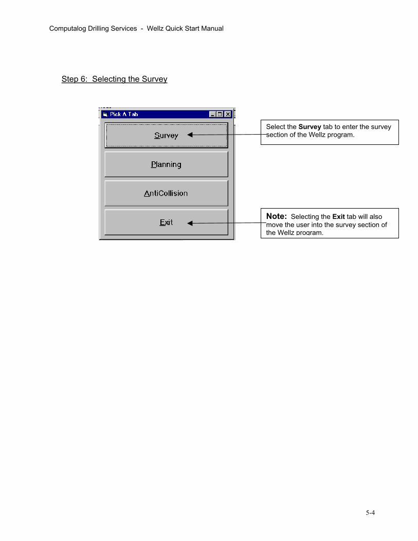
Computalog Drilling Services - Wellz Quick Start Manual
Step 6: Selecting the Survey
Select the Survey tab to enter the survey section of the Wellz program.
Note: Selecting the Exit tab will also move the user into the survey section of the Wellz program.
5-4

Computalog Drilling Services - Wellz Quick Start Manual
3. SETTING SURVEY VIEW OPTIONS
3.1. Changing Units
3.2. Changing Decimal Places Displayed
To change the units used for the current Wellz file, select Units under the Tools drop down menu. The Units dialogue box will appear just as it did when you started a new Wellz file. Note: Changing the units will convert all previously entered survey depth values to the appropriate new measured depth value (ie. 100 feet will change to 30.48 m). The DLS values may change slightly since the 30 m interval does not exactly match a 100 foot interval.
Select Set DecDisplayed unddrop down mendialogue box wappear.
Another method of changing the units usedis to single click the green box at the top right corner of the main Wellz survey screen. The Units dialogue box will then appear.
imal Places er the Tools u. A small ill then
5-5

Computalog Drilling Services - Wellz Quick Start Manual
3.3. Arranging Columns
Select Pick Column Arrangement under the Tools drop down menu to pick a new columarrangement.
n
To customize your column arrangement select Create Custom and follow the instructions.
3.4. Hiding and Unhiding The Survey Tool Bar Tab
To hide the Survey Tool Bar Tab on the left side of the main Wellz survey screen, select ToolBars/Tabs under the Tools drop down menu and click Hide. To view the Survey Tool Bar Tab on the left side of the screen, follow the same steps and click Survey.
The Survey Tool Bar Tab.
5-6

Computalog Drilling Services - Wellz Quick Start Manual
4. INPUTTING SURVEYS
Step 1: Inputting the Tie On Point
Step 2: Entering surveys
The first survey station is the Tie On Point. The Tie On Point row will appear in yellow as the active row. Hit the Enter key to input from leftto right through the required fields starting with measured depth (MD). The default Tie On Point is all zeros. Note: Lat = North
Dep = East
The Tie On Point can also be edited at any time by double clicking the tie on point row. The“Edit Survey “ dialogue box will then appear.
Once the Tie On Point has been properly entered, click once on the Departure (Dep) field and hit the Enter key to go to thenext r
ow.
5-7

Computalog Drilling Services - Wellz Quick Start Manual
Input consecutive surveys (MD, INC, AZM) below the Tie On Point as required by hitting the Enter key.
Step 3: Editing The Survey Data
To edit an existing survey station, double click the desired row. Or Single click on the most recent survey station highlighted in yellow. Or Single click the Edit Survey button to enter a row number and access the “Edit Survey” dialoguebox.
To insert a single survey station, click the Insert Survey button to access the “Insert Survey Point” dialogue box.
To delete a survey station from the survey file, click the Delete Row button and input the row number or row numbers that you wish to delete. Tip: Click on the desired row that you want to delete before clicking the Delete Row button. This will ensure that the row number in the dialogue box corresponds to the row that you want to delete.
5-8

Computalog Drilling Services - Wellz Quick Start Manual
5. INSERTING INTERPOLATED TEXT LINES FOR PRINT
The following are the steps required to interpolate surveys with text lines that can be inserted onto your survey printout.
Step 1
To add text to your survey file, select Edit Text Lines under the Tools drop down menu. The Text Lines For Active Well dialogue box will then appear.
Step 2
Insert an interpolated text line by 1: Selecting an Interpolation Method, 2: Entering a Depth, 3: Entering a Text Line and 4: Clicking Add.
Note: The interpolated text line survey depths can also be inserted into your survey file by clicking the Apply, Interpolate Text Line Depths to Sheet.
To edit an existing text line, double clickon the desired field inthe table at the top of the dialogue bo
x.
To delete an existing row, click on the desired row and click the Delete button.
To save your changes and exit the dialogue box, click OK. To save your changes without closing the dialogue box, click Apply. To close the dialogue box without saving your changes, click Close.
5-9

Computalog Drilling Services - Wellz Quick Start Manual
6. QUICK PRINTING
Step 1: Access the Quick Print Options Dialogue Box
Step 2: Configure the Quick Print Options Dialogue B
Text lines with or without the interpolated Text Line Points can be inserted into thesurvey print out.
The Start Column and End Column, cthe columns in the main Wellz survey wselected.
To print out a listing of the survey file, select Quick Print under the File drop down menu. Note: The Printer Settings may have to be configured before you are able to print properly.
ox To select the range of survey stations that you wish to print, select Row Number, MD or TVD and the Start and End points.
Select to indicate
To include interpolations on the printout, select Interpolate by MD or TVD andclick the Apply New Settings button that appears.
The Quick Print can be Previewed, Printed or Canceled.
orresponding to indow, can also be
Row Numbers and extrapolated surveys (EXT).
5-10

Computalog Drilling Services - Wellz Quick Start Manual
7. TARGETS
Step 1: Access the Targets Dialogue Box
To access the targets associated with the current Wellz file, select Show Targets under the Planning drop down menu.
Step 2: Add Targets
The location and orientation of multiple targets can be added toon the table below. The user has the option of inputting the La(east) OR the Closure distance and Closure Azimuth from su
To add more targets, expand the size of the above table by clicking the Add Target bu tton.
To delete a target, click the Delete Target button and enter the appropriate row number.
The targets dialogue box can also be accessed by clicking the Targets buttonon the Survey Tool Bar Taand clickin
b
g Show Targets.
the current Wellz file by clicking titude (north) and Departure rface for each target.
5-11
A target radius can be specified in the Targets dialogue box.
Note: The target will not appear on the plan view graphics unless the Graph Target Points is turned on.
Graph Target Points.
To do this, select Options under the Graphics drop down menu and check the

Computalog Drilling Services - Wellz Quick Start Manual
8. PROJECTING TO BIT
Step 1: Open Project To Bit dialogue box
Step 2: Set Parameters For Projection To Bit
To access the Project To Bit dialogue box, select Project To Bit under the Survey drop down menu.
The Project To Bit dialogue box can also be access using the Project To Bit button on the Survey Tool Bar Tab.
These are the survey numbers to the last survey station.
If you wish, the projection to bit survey can be inserted into the survey file by clicking the Insert in Active Well button. Note: The inserted survey will have an EXT row number and all row numbers thereafter will be EXT extension. To remove the EXT rows, use the Delete
Once the Build Rate, Turn Rate and Change in MD have been entered, click Calculate. The projected survey to the bit will appear in the adjacent row.
Input the estimated Build Rate, Turn Rate to a specific measured depth distance ahead (Change in MD). Note: When projecting to the bit, the Change in MD distance is the distance from the bit to the survey tool sensor.
button.
5-12

Computalog Drilling Services - Wellz Quick Start Manual
9. PROJECTING AHEAD
9.1. Projecting To A Target
Step 1: Open Project Ahead Dialogue Box
To access the ProjectAhead dialogue box, select Project Ahead under the Survey drop down menu.
The Project Ahead dialogue box can also be accessed using the Project Ahead button on the Survey Tool Bar Tab.
5-13

Computalog Drilling Services - Wellz Quick Start Manual
Step 2: Set Parameters For Projecting To a Target
The survey station that the projection is tied to can be selected by entering the survey row number or by clicking the Get Next Survey or Get Previous Survey buttons.
The target for the projection can be selected by enteringthe target row number or by clicking the Get Next Target orPrevious Target buttons.
Get
The Straight Line Projections from the selected survey station to the selected target are displayed above. This projection method indicates to the directional driller whether the well is lined up to hit inside or outside the target radius. Note: Remember to enter a target radius for the selected target.
The Build Rate To Target TVD and Target Inc is displayed below. Note: This is NOT the build rate to target. Note: For this number to be meaningful, the desired target inclination and target TVD must be entered in the Target info (Edit Targets).
To create extrapolations using various projection methods, click the Project Ahead button.
To edit or add a target to the list, click the Edit Targets button
The Required Correction To Targets,calculated from the selected survey station to the selected target, are displayed above. The required correction uses a constant dogleg to target projection method.
below (right).
5-14

Computalog Drilling Services - Wellz Quick Start Manual
9.2. Projecting Ahead (Extrapolating)
Step 1: Set Parameters For Projecting Ahead
Select from one of the seven Projection Methods below.
Note: The size of each step can be changed by checking the Set Step Sizes Mode box.
Parameter Values can also be adjusted by clicking the Step Buttons below. This input method calculate autom y
will aticall
To deextrapDeletbutton
Following the last survey station, the Extrapolation (EXT) will appear in the above table. Each time the Projection Method and/or parameter values change, the EXT row will change accordingly.
To add the extrapolation(s) to the survey file, click the Ok (add to surveys) buttonappear in the survey file with EXT row numbers.
To close this dialogue box without adding the extrapolation(s) to the survey file, click
Note: The extrapolated survey station(s) can be removed from the survey file latesteps to remove an actual survey station (row).
Note: When a Projection Method is selected, the default parameter values that appeaare linked to thecorresponding selected t
r
arget alues.
Target buttons.
v To change the target, select theNext Target or Previous
Once a Projection Method has been selected, the appropriate variables will appearbelow. To adjust the parameter values, click on a box and enter a new value Click Calculate after all variables are entered to update the extrapolation in the table below.
lete the last olation, click the
e Projection .
To extrapolate from an extrapolation, click the Post Projection button and select another Projection Method.
5-15
. The extrapolation(s) will
the Close button.
r by following the same

Computalog Drilling Services - Wellz Quick Start Manual
10. INTERPOLATING 10.1. Inserting a Single Interpolated Point
The following steps will allow the user to insert a single interpolated point. The interpolated point will appear as an actual survey station in the Wellz file.
Step 1: Select an Interpolation Method
Note: To remove the inserted interpolated point, follow the saactual survey station (row). The current version of wells does not distinguish interpolated ssurvey stations. To indicate that a survey station is an interpolsame interpolated depth following the steps outlined in Sectionstate that the survey station is an interpolation. Ex. “INTERPO
Insert an interpolated point by clicking Insert Interpolated Point under the Tools drop down menu. Select one of the interpolation options (Measured Depth, TVDor Subsea). A dialogue box willthen appear where you can enter the desired interpolation depth.
After an interpolated depth has been entered, the Show Interpolation dialogue box will then appear. To insert the interpolated point as a survey row, click the Insertin Active Well button. To close the dialogue box without inserting the interpolation, click the Close button.
me steps used to remove an
urvey stations with actual ation, insert a text line at the 5. The text line should clearly LATION”.
5-16

Computalog Drilling Services - Wellz Quick Start Manual
10.2. Viewing and Printing Multiple Interpolations
To create multiple interpolations across the entire survey file that can only be Viewed or Printed, follow the steps outlined below.
Note: The multiple interpolated points do not become survey staviewed or printed.
1. Select Show Plan Survey under the Planning drop down menu. 2. Select Interpolate by Measured Depth or Interpolate by TVD that the distance will be calculated on. 3. Enter the desired interpolated distance.
Note: To remove (hide) the interpolated points follow the same steps above and select Hide Interpolated points.
tions and can only be
5-17

Computalog Drilling Services - Wellz Quick Start Manual
11. GRAPHICS
11.1. The Graphics Menu
The Graphics Menu allows the user to change the look of the Graphics Window.
When multiple Wellz files are open in memory, each file can be turned OFF or ON using the Pick Wells to Display.
To open a graphics window, selected the desired view (3-d, Plan or Section). To close the graphics window, select Hide Graphics.
To modify the view of the graphics window relative to the Active Well, select from the list.
Use this option when viewing the 3-d View. A dialogue box will appear requesting the number of frames for 360 degrees of rotation. Enter a suitable value (180) and the 3-d View will rotate
Select Options to further modify the graphics window. (Section 11.3)
11.2. Plan and Section Views
Step 1: Select the View
Select Plan View or Section View under the Graphics drop down box. A Wellz – grapwindow will appear on the left side of the screen. A second windowwill also appear on the right side of the screen containing Graphics Parameters with Well
hic
Parameters.
Note: The Well Parameters portion of the screen is a smaller version of the main Survey screen and will not be further discussed in the graphics section of the manual.
5-18

Computalog Drilling Services - Wellz Quick Start Manual
Step 2: Modify The Graphic Parameters PLAN VIEW GRAPHIC PARAMETERS
Scale All - Decrease the Scale All to zoom in and increase the Scale All to zoom out. The Scale All value affects the east-west and north-south axis together.
Box Center East - Adjusts the East coordinate of the graphics view (box) center. Box Center North - Adjusts the North coordinate of the graphics view (box) center. Sector Size - The sector size is the grid box size outlined in black. Increase the sector size to reduce the number of grid lines. Decrease the sector size to increase the number of grid lines. Scale East - Decrease the Scale East to expand the east-west axis. Scale North - Decrease the Scale North to expand the north-south axis. Sector East - The sector size in the East – West direction.
- Tip: Match the Sector East value with the Scale East value. Sector North - The sector size in the North – South direction.
- Tip: Match the Sector North value with the Scale North value.
Note: To view your changes to the graphics window, the Calculate button must be selected.
Note: Using the up and down arrow at the right side of the graphics parameters screen is a quick way to modify the graphics view. The step sizes can be adjusted by checking the Set Step Sizes Mode box. To exit the Set Step Sizes, uncheck the Set Step Sizes Mode box.
5-19

Computalog Drilling Services - Wellz Quick Start Manual
SECTION VIEW GRAPHIC PARAMETERS
Scale All - Decrease the Scale All to zoom in and increase the Scale All to zoom out. The Scale All value affects the vertical and horizontal axis together.
Box Center TVD - Adjusts the TVD of the graphics view (box) center. Section Displacement - Adjusts the Section Displacement of the graphics view (box) center. Sector Size - The sector size is the grid box size outlined in black. Increase the sector size to reduce the number of grid lines. Decrease the sector size to increase the number of grid lines. Scale Vertical - Decrease the Scale Vertical to expand the vertical axis. Scale Horizontal - Decrease the Scale Horizontal to expand the horizontal axis. Sector Vertical - The sector size in the vertical direction.
- Tip: Match the Sector Vertical value with the Scale Vertical value.
Sector Horizontal - The sector size in the horizontal direction. - Tip: Match the Sector Horizontal value with the Scale Horizontal value.
Note: To view your changes to the graphics window, the Calculate button must be selected.
Note: Using the up and down arrow at the right side of the graphics parameters screen is a quick way to modify the graphics view. The step sizes can be adjusted by checking the Set Step Sizes Mode box. To exit the Set Step Sizes, uncheck the Set Step Sizes Mode box.
5-20

Computalog Drilling Services - Wellz Quick Start Manual
11.3. Graphics Options
Select Options under the Graphics drop down menu to access the graphics options below.
To change the color, thickness and dot line interval for the Active Well, Select the Set Color and Line Type of Well. Red is generally used for the “Proposed” line trajectory and blue is used as the “Actual” line trajectory.
Primarily used to alter only the 3-d view. Also used to change the darkness of the secondary grid lines for all views (ie. Grid Lightener).
There are three options for adding points to the graph: 1. Graph Survey Points will place a point at every survey station. 2. Graph Points of Interest will graph points from the Points of Interest table. 3. To remove all points from the graph, select Do Not Graph Points.
Select Graph Target Points to display all the targets entered in the Target table on the graph. Note: Remember to enter a radius for the target in the Target table.
To add, remove or edit the Points of Interest table, select the Edit Points of Interest. To view the points of interest on the graph, select Graph Points of Interest.
NmC
The coordinate system used for the graphic view can be selected as: Field Coordinates and Subsea depths OR Local Coordinates and TVD depths
ote: The Local Coordinate and TVD system puts the surface location for all Wellz files in emory at a latitude(north) = 0, departure(east) = 0 and KB starts at 0 m TVD. The Local oordinate system is the most commonly used coordinate system.
Note: The Field Coordinate and Subsea system is based on an arbitrary field center location that all well surface locations can be referenced from. This coordinate system is useful when viewing multiple wells in an area and/or producing anti-collison reports with Wellz. THE FIELD COORDINATE SYSTEM SHOULD ONLY BE USED WHEN THE NORTH OF FIELD CENTER, EAST OF FIELD CENTER AND KB ELEVATION VALUES FOR ALL WELLZ FILES IN MEMORY ARE PROPERLY ENTERED IN THE EDIT HEADER DATA DIALOGUE BOX.
5-21

1
© 2007 Weatherford. All rights reserved.
Directional Drilling IMartillos de Perforación Dailey™ y los cabrestantes de martillos o aceleradores(Jar Slingers)
Revision 1
© 2007 Weatherford. All rights reserved.
• Martillos/Jar
– Una herramienta de sacudida que almacena y liberala energia dentro del BHA
– La liberacion de energia es usada para liberar unasarta de perforacion que se ha atorado o pegado en el hoyo al producir una fuerza de impulso e impacto
• Cabrestante/Aceleradores/Slinger
– Una herramienta de sacudida secundaria que se coloca directamente encima del jar
– Usada para complementar al martillo de modo de incrementar la eficiencia al proveer energía extra para la operación de martilleo
Jars & Slingers
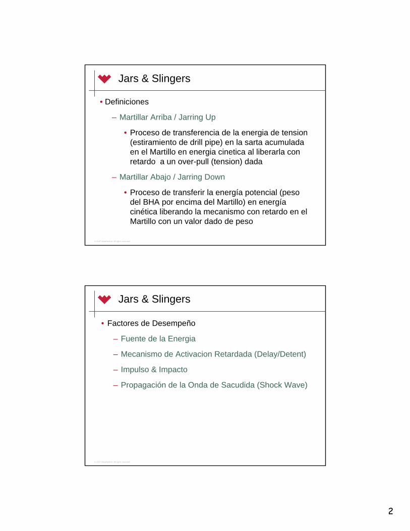
2
© 2007 Weatherford. All rights reserved.
Jars & Slingers
• Definiciones
– Martillar Arriba / Jarring Up
• Proceso de transferencia de la energia de tension (estiramiento de drill pipe) en la sarta acumuladaen el Martillo en energia cinetica al liberarla con retardo a un over-pull (tension) dada
– Martillar Abajo / Jarring Down
• Proceso de transferir la energía potencial (peso del BHA por encima del Martillo) en energíacinética liberando la mecanismo con retardo en el Martillo con un valor dado de peso
© 2007 Weatherford. All rights reserved.
Jars & Slingers
• Factores de Desempeño
– Fuente de la Energia
– Mecanismo de Activacion Retardada (Delay/Detent)
– Impulso & Impacto
– Propagación de la Onda de Sacudida (Shock Wave)

3
© 2007 Weatherford. All rights reserved.
Jars & Slingers
• Factores de Desempeño
– Fuente de la Energía
• Martillado Arriba /Jarring Up– La energía para la operación de martillado arriba es
suministrada al tensionar la sarta
– La tensión es creada al (sobre tensionar-) jalar (estirar) la tuberia
– Mayor sobre tensionado (overpull) = Más energía
• Martillado Abajo / Jarring Down– La energía para la operación de martillado abajo es
suministrada al comprimir la sarta con gran peso por encimadel martillo
– La compresión es creada al suavemente soltar el peso aplicado sobre la sarta encima del martillo
– Más peso = Más energía
© 2007 Weatherford. All rights reserved.
Jars & Slingers
• Factores de Desempeño– Mecanismo de Activación Retardada (Delay / Detent)
• Un sistema ó dispositivo dentro del martillo que permite a la energía creada al sobre tensionar o comprimir la sarta que se acumule y entonces se libere bruscamente en un tiempodesignado
• Tipos– Mecánicos
» El disparador es un gancho o resorte, no hay retardo si la cargaumbral es excedida de una vez
– Hidráulico
» El disparador es un fluido forzado a traves de chorros/jets en un tiempo, el retardo del disparador depende de la carga (peso) y el tiempo
– Hidro-mecánico
» Ambos mecanismos hidráulico y mecánico están presentes en el martillo (ej. hidráulico martilla hacia arriba, mecánico martillahacia abajo)

4
© 2007 Weatherford. All rights reserved.
Jars & Slingers• Factores de Desempeño
– Impulso & Impacto
• Impacto (magnitud de la onda de choque)– Es la fuerza/energía transmitida/creada por una colisión
– En un martillo, esta es la fuerza creada cuando el martillo golpea el yunque
– KE = ½ x M V2
• Impulso (duracion de la onda de choque)– Es el producto del (Promedio de la fuerza aplicada) X (Tiempo que la fuerza
actua sobre el objeto)
– F∆t = m∆v, donde:
» F – Fuerza Aplicada (N ó lbf)
≈ ∆t – Tiempo (sec)
» m – Mass (kg ó libras)
≈ ∆v – Cambio en la velocidad (m/sec ó ft/sec)
– El termino m∆v es tambien llamado cambio en el momento
– Para un martillo, esta es la duración de una onda de sacudida o choque queviaja a través de la tuberia
© 2007 Weatherford. All rights reserved.
Jars & Slingers
• Factores de Desempeño– La relación entre Impacto y Impulso
– Menor Golpe = Mayor impacto
– Mayor Golpe = Mayor impulso
– La disminución de la masa ó el aumento de la tensión resulta en un aumento de la velocidad de impacto

5
© 2007 Weatherford. All rights reserved.
700600500400300200100
0-100-200-300
0 .02 .04 .06 .08 .10 .12 .14
Impa
cto
Jar (
X100
0) lb
s
Segundos
Impacto (lbs)
ImpulsoImpacto x segundos(lbs-sec)
Jars & Slingers
• Impacto e Impulso en el lugar del atascamiento
© 2007 Weatherford. All rights reserved.
Jars & Slingers
• Propagación de la Onda de Choque– Es la transmisión del impacto/impulso generado
por el martillo a través y a lo largo del BHA– La onda de sacudida de energia suficiente debe
alcanzar la profundidad del punto de atascamientopara ser efectiva en liberar al BHA

6
© 2007 Weatherford. All rights reserved.
Tipos de Martillo/Jar
• Martillos Mecánicos
• Martillos Hidráulicos
• Martillos Hidro-Mecánicos
© 2007 Weatherford. All rights reserved.
Martillos de Perforación Mecánicos
• Aplicaciones
– Pozos Verticales
– Pozos Direccionales con ángulo < 30º
– Pozos Geotermales
– Se usa como martillo de la sección superior cuandose usan varios martillos en tandem en una sarta

7
© 2007 Weatherford. All rights reserved.
Martillos de Perforación Mecánicos
• Ventajas– Tecnología probada en Campo– Operación directa de Empuje / Jale– Puede ser accionado tanto hacia Arriba como hacia Abajo– Proceso de re-armado rápido– Disparo inmediato cuando se sobrepasa el sobretensionado
especificado– Puede operar aún con una falla de sellos inesperada– Costo menor
• Desventajas– Sobre-tensión limitada– Afectado por el torque de perforación– Inútil en pozos horizontales/ rango extendido >30º de ángulo
© 2007 Weatherford. All rights reserved.
L.I. MECHANICAL DRILLING JAR - SPECIFICATIONS
Outside Diameter (in.) 4 3/4 6 1/4 6 7/8 7 3/4
Inside Diameter (in.) 2 2 1/4 2 1/2 2 3/4
Tool Joint Size (API) NC-383 1/2 IF
NC-464 1/2 XH4 1/2 IF
5 1/2 Reg. 6 5/8 Reg
Tensile Yield* ( x 1000 lbs.) 440 740 962 1,148
Torsional Yield* ( x 1000 ft. lbs.) 15 27.2 46 66.3
Up Stroke (lbs.) FactoryDown Stroke (lbs.) Settings
69,70032,900
94,30037,600
98,40042,300
102,50042,300
Max. Overpull Up/Down (lbs.) 75,000 118,000 120,000 125,000
Approx. Length Extended(ft. - in.) 30' - 6" 34' - 0" 34' - 6" 35' - 6"
Approx. Weight (lbs.) 1,340 2,500 3,150 4,000
Free Travel Upstroke (in.) 8 5/8 7 1/8 7 7/8 7 3/4
Free Travel Downstroke (in.) 8 8 8 8 1/4
Max. BHT (°F) 325 325 325 325
Pump Open Area (sq. in.) 7.7 11.0 14.2 17.7
Martillos de Perforación Mecánicos
• Especificaciones Mecánicas del Martillo de PerforaciónMecánico

8
© 2007 Weatherford. All rights reserved.
Martillos de Perforación Mecánicos
• Principio de Operación
– La herramienta contiene un sistema de enganche / disparomecánico
– Cuando el enganche/disparo es excedido, el martillo se dispara, liberando la energía acumulada hacia la sarta de perforación
Barrel LowerConnector
UpperPacking Body
JayStem
WashpipeSpringStem
Polished Stem Upper Connector Lower Packing BodyJay Rollers Torque Spring
© 2007 Weatherford. All rights reserved.
Martillos de Perforación Mecánicos
• Procedimientos Operacionales– Levantado para la sarta
• El martillo mecánico de perforación se despachaen posición de armado (cargado/listo), solo (8”/20.3 cm) del mandril pulido está expuesto
• El martillo usualmente se arma (carga) cuando se saca del hoyo
• Se recomienda correr al hoyo el martillodeshabilitado (descargado)
• El martillo pudiera ser corrido en posición de armado (habilitada) en ciertas circumstancias (ej. operaciones de pesca)

9
© 2007 Weatherford. All rights reserved.
Martillos de Perforación Mecánicos
• Procedimientos Operacionales
– Des-habilitado/des-armado del Martillo
• Si tiene HWDP/DC encima del martillo, coloque las cuñas en el cuerpo del martillo debajo del mandril
• Libere la rotaria y usando dos llaves de mordaza, rote el mandril 1/8 de giro a la izquierda. Manteniendo este giro de 1/8, levante la sarta para abrir el martillo
• En este punto, cerca de unos 16”/40.6 cm del mandrilestarán expuestos. El martillo esta listo para ser corrido en el hoyo.
• Nota: NO gire el mandril más de 1/8 de giro a la izquierda. Si lo hace se desenrosacará la conexión y causará que el martillo comience a chorrear o gotear.
© 2007 Weatherford. All rights reserved.
Martillos de Perforación Mecánicos
• Procedimientos Operacionales
– Martillado Arriba
• 1. Cargue al martillo. Ponga peso de la columna de sondeo(sarta) sobre el martillo para ponerlo en la posición armado.
• 2. Jale la sarta hasta que la fuerza umbral de ajuste del martillo sea alcanzada y se dispare.
• 3. Re-cargue al martillo. Coloque peso a la columna de sondeo hasta un monto ligeramente por debajo del peso de la sarta que está por encima del martillo
– Una señal reconocible, como es una burbuja en la aguja del indicador de peso, nos indicará que el martillo ha concluidocompletamente su movimiento y se ha recargado
• 4. Repita según se requiera

10
© 2007 Weatherford. All rights reserved.
Martillos de Perforación Mecánicos
• Procedimientos Operacionales
– Martillado Arriba
• Estimando el over-pull (sobre-tensionado) requerido para disparar al martillo
© 2007 Weatherford. All rights reserved.
Martillos de Perforación Mecánicos
• Procedimientos Operacionales
– Martillado Abajo
• 1. Cargue al martillo. Levante el peso de la sarta para la posicionde armado (a la “cocked position”)
• 2 . Ponga peso sobre la sarta hasta que la fuerza umbral del sea alcanzada y se dispare el martillo
– Nota: La embolada hacia abajo no es perceptible en la mayoria de los casos como lo hace la embolada hacia arriba. En hoyos profundos y cuando se usa un martillo pequeño, el movimiento hacia abajo puedeser detectado solo por el indicador de peso
• 3. Re-armado del martillo. Levante la sarta hasta que la lectura en el indicador de peso este ligeramente por encima del peso de la “sarta que esta por encima del martillo”
– El movimiento libre y ligero en el indicador de peso nos indicarán queel martillo ha sido cargado
• 4. Repita según se requiera

11
© 2007 Weatherford. All rights reserved.
Martillos de Perforación Mecánicos
• Procedimientos Operacionales
– Martillado Abajo
• Estimando el peso requerido para dispararel martillo
© 2007 Weatherford. All rights reserved.
Martillos de Perforación Mecánicos
• Procedimientos Operacionales
– Ajustando la Fuerza de Martillado
• Para hacer que el martillo accione a mayores cargas, aplique y sostenga un torque de ½ giro a mano derecha en la sarta en un tiempo hasta que el ajuste intentado es logrado
– Un torque excesivo a la mano derecha hace imposible alcanzar el tensionado suficiente para disparar el martillo
– Si un torque grande a mano derecha es aplicado, simplemente libereel torque; el martillo retornará a su ajuste original
• Para hacer que el martillo dispare con cargas más ligeras, aplique y mantenga un ½ giro de torque a la mano izquierda por un tiempohasta que el ajuste deseado es alcanzado
– Un torque excesivo a la mano izquierda mantiene al martillo fuera de su armado y reduce el efecto de martillado
– Si un torque grande a mano izquierda es aplicado, simplemente libereel torque; el martillo retornará a su ajuste original

12
© 2007 Weatherford. All rights reserved.
Martillos de Perforación Mecánicos
• Procedimientos Operacionales
– Inspección después de Sacar del Hoyo (POOH)
• 1. Lave de lodo el “mandril pulido” y a través de los orificios y aberturas en la parte superior del cuerpo para evitar que el lodo se seque y se endurezca o se quede dentro de la herramienta
– NOTA: La solidificación del lodo puede afectar adversamente el funcionamiento apropiado del martillo
• 2. Pruebe el mecanismo del martillo. Use dos juegos de llaves de mordazas, y estire el martillo. Asegurese que el mandrel se muevaen ambas direcciones de la posición de armado
• 3. Cheque todas las soldaduras de los “roller” y los pernos de “torque” por posible goteo de aceite. Si se sospecha de unalavadura, levante al kelly, bombee a través de la herramienta bajopresión de bombas y verifique por escapes o goteo.
© 2007 Weatherford. All rights reserved.
Martillos de Perforación Hidráulicos
• Aplicaciones
– Pozos Verticales/Direccionales con elevado torque y arrastre (drag)
– Pozos Horizontales/Rango Extendido
– Martillo de la sección inferior cuando se usan dos martillos en tandem en una sarta
– Circumstancias con capacidad limitada de sobre-tensionado

13
© 2007 Weatherford. All rights reserved.
Martillos de Perforación Hidráulicos
• Ventajas– Cargas de disparo variables– Desafectado por torque & temperatura– Sellos y hombro de impacto protegidos– Sin debilitamiento “bleed-off”– Aumento en los limites de sobre-tensionado– Tiempo de Retardo Consistente
• Desventajas– La energía térmica afecta a los sellos
© 2007 Weatherford. All rights reserved.
HYDRAULIC DRILLING JAR - SPECIFICATIONS
Outside Diameter (in.) 4 3/4 4 3/4 6 1/4 6 1/2 7 7 3/4 8 9 1/2
Inside Diameter (in.) 2 1/16 2 1/4 2 1/4 2 3/4 2 3/4 3 3 3
Tool Joint Size (API) NC-383 1/2 IF
NC-383 1/2 IF
NC-464 1/2 XH
NC-504 1/2 IF 5 1/2 FH 6 5/8 Reg 6 5/8 Reg. 7 5/8 Reg
Tensile Yield* ( x 1000 lbs.) 436 500 832 934 1,200 1,600 1,750 2,300
Torsional Yield* ( x 1000 ft. lbs.) 21.2 20 49.3 56.2 76.4 76.4 105 160
Max. Overpull Up/Down ( x 1000 lbs.) 95 85 200 175 220 260 300 500
Approx. Length Extended (ft. - in.) 32' - 0" 32' - 0" 33' - 0" 33' - 0" 33' - 0" 33' - 0" 33' - 0" 33' - 0"
Approx. Weight (lbs.) 1,200 1,200 2,050 2,400 3,000 3,500 3,800 5,500
Free Travel Up/Down Stroke (in.) 5 5 1/2 6 1/4 6 1/2 6 1/2 7 7 7
Total Stroke (in.) 13 1/2 15 16 1/2 17 17 19 1/2 19 1/2 19 1/2
Max. BHT ( °F ) 400 400 400 400 400 400 400 400
Pump Open Area (sq. in.) 9.6 10.3 15.9 19.6 23.8 28.3 28.3 38.5
Martillos de Perforación Hidráulicos
• Especificaciones del Martillo Hidráulico
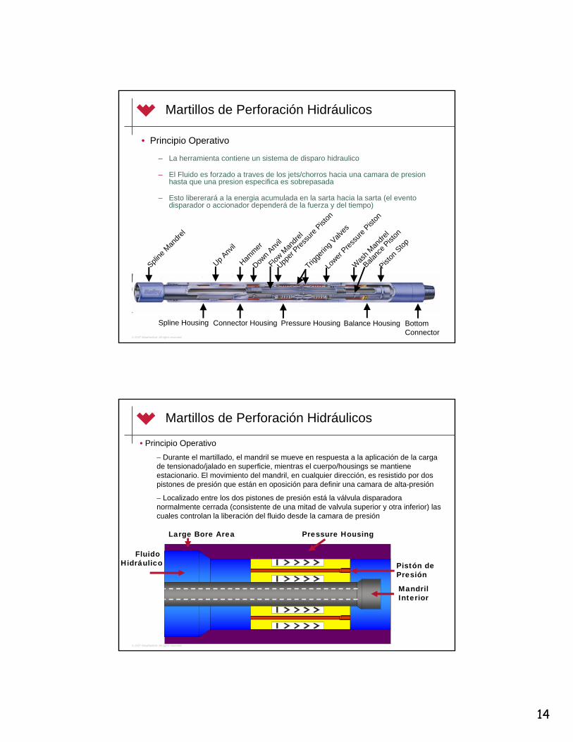
14
© 2007 Weatherford. All rights reserved.
Martillos de Perforación Hidráulicos
• Principio Operativo
– La herramienta contiene un sistema de disparo hidraulico
– El Fluido es forzado a traves de los jets/chorros hacia una camara de presionhasta que una presion especifica es sobrepasada
– Esto libererará a la energia acumulada en la sarta hacia la sarta (el eventodisparador o accionador dependerá de la fuerza y del tiempo)
Spline
Mandre
l
Up Anv
il
Hammer
Down A
nvil
Lower
Pressu
re Pist
on
Was
h Man
drel
Balanc
e Pist
on
Piston
Stop
Upper
Pressu
re Pist
on
Spline Housing
Trigge
ring V
alves
Flow M
andre
l
Connector Housing Pressure Housing Balance Housing Bottom Connector
© 2007 Weatherford. All rights reserved.
Martillos de Perforación Hidráulicos
FluidoHidráulico
Large Bore Area Pressure Housing
Pistón de Presión
MandrilInterior
• Principio Operativo– Durante el martillado, el mandril se mueve en respuesta a la aplicación de la cargade tensionado/jalado en superficie, mientras el cuerpo/housings se mantieneestacionario. El movimiento del mandril, en cualquier dirección, es resistido por dos pistones de presión que están en oposición para definir una camara de alta-presión
– Localizado entre los dos pistones de presión está la válvula disparadoranormalmente cerrada (consistente de una mitad de valvula superior y otra inferior) lascuales controlan la liberación del fluido desde la camara de presión

15
© 2007 Weatherford. All rights reserved.
Martillos de Perforación Hidráulicos
• Principio Operativo– Martillado Arriba
• El piston de presión inferior se mueve hacia arriba con el mandril, mientras que el hombro en el housing evita que el piston superior se mueva
• Una presión suficiente es generada entre los pistones de presión para resistir la aplicación de la carga hasta que la válvula disparadora es mecanicamente abierta por el dispositivoactuador
• El retardo de tiempo (desde que la carga es aplicada hasta que la válvula disparadora abre) eslogrado por un mecanismo de medida hidráulica que controla la velocidad a la cual el pistóninferior de presión se mueve hacia el pistón superior de presión
• El pistón inferior de presión debe moverse a una distancia predeterminada antes de que el dispositivo actuador contacte su respectiva media válvula y fuerce a la válvula disparadora a abrir
• El retardo establecido es designado para permitir suficiente tiempo al operador para jalar la carga requerida antes de que la válvula disparadora abra
• Cuando la valula disparadora abre, el fluido de alta presión en la cámara que estabaaguantando la sobre tensión es liberado de la camara para la camara de presion hidrostática
• Ya que no hay más resistancia al movimiento del mandril en relacion al cuerpo del housing, el martillo se mueve hasta que el martillo impacta el yunque
• Para un martillado hacia arriba de nuevo, la herramienta es retornada al neutral al bajar la sarta y entonces aplicar una nueva sobretensión. Esta acción puede repertirse cuantas vecessea necesario
© 2007 Weatherford. All rights reserved.
Martillos de Perforación Hidráulicos
• Principio Operativo
– Martillado Abajo• Una acción similar pero opuesta ocurre
– El pistón de presión superior se mueve hacia abajo junto con el mandril en respuesta al peso aplicado sobre la sarta por arriba, mientras que el hombro en el housing previene al pistóninferior de presión de moverse.
– En el martillado hacia abajo, el disparo ocurre cuando el pistónsuperior se ha movido lo suficiente hacia el pistón inferior de presión para forzar la valvula disparadora a abrir.
– Las funciones separadas de martillado arriba y abajo podria ser logrado en cualquier secuencia; es decir, arriba solo, abajo solo, ó arriba y abajo

16
© 2007 Weatherford. All rights reserved.
Martillos de Perforación Hidráulicos
• Principio Operativo
– Abrazadera del Mandril
• El martillo se despacha con una abrazadera en el cuello del mandril instalada. Déjela instalada hasta que el martillo esta listo para bajar por la mesa rotariapara proteger la sección pulida expuesta del mandril y prevenir una operaciónno intencional de la herramienta.
• Precaución: No ponga llaves o cuñas en la sección expuesta del mandril, o no retire la abrazadera del mandril a no ser que el martillo este en tensión. Estasacciones pudieran resultar en daños al equipo.
• Para remover la abrazadera del mandril:
– Levante el peso de las cuñas y coloque el martillo en tensión
– Remueva la correa de envio, y coloque el perno de cierre “lock pin” haciaarriba hasta que el enganche en forma de U pueda ser abierto
– Separar las dos mitades del cuerpo, y quitar la abrazadera
– Mantenga la abrazadera en la locación para ser usada cuando el martillosea sacado del hoyo y puesto en el rack.
© 2007 Weatherford. All rights reserved.
Martillos de Perforación Hidráulicos
Principio Operativo de la Abrazadera del Mandri
Para instalar la abrazadera del mandril:– Visualmente inspeccione todas las partes por presencia de
fisuras o partiduras. No use la abrazadera si esta está dañadao no puede ser operada como se describe. Puede resultar en serias heridas
– Instale la abrazadera en el martillo con este en tensión y con el extremo del “lock pin” hacia arriba. El resorte de enganche(latch spring) debe retornar el enganche a la posición cerrada
– Empuje al perno (lock pin) hacia abajo hasta que la cabeza del perno enganche. El extremo del perno puede ser observadosobresliendo a traves del estirón mas bajo, y el engancheestará cerrado cuando el perno de cerradura se asientacompletamente
– Instalar la correa del envío alrededor de la abrazadera

17
© 2007 Weatherford. All rights reserved.
Martillos de Perforación Hidráulicos
• Principio Operativo
– Levantado
• Siempre use el sustituto de levantar y el protector de rosca en la conexion pin
• Si el martillo se carga (9” / 22.86 cm del mandril pulido expuesto) en superficie, este puede ser facilmente disparado con un pequeño tensionado
– Instale el perro de collarín en el martillo para prevenir que se caiga al fondo
– Sostenga el peso debajo del martillo sea en las cuñas o al cerrar los rams de la BOP sobre el BHA
– Levante 5,000-10,000lb / 22.2-44.5 kN con el elevador
– Con esta extrema baja carga, por cerca de 5 minutos se requerirán paraque el martillo dispare
– El martillo esta plenamente extendido cuando 17” / 43.2 cm del mandrilpulido están expuestos
– Siempre use abrazaderas de mandril cuando el martillo esta fuera de la mesa rotaria
© 2007 Weatherford. All rights reserved.
Martillos de Perforación Hidráulicos
• Principio Operativo
– RIH (Corriendo hoyo abajo)
• Comience y pare suavemente cuando baje con el martillo paraevitar abrir y cerrar el martillo repetidamente los cuál causaria queel martillo se cargue
• Pase a través de los sitios angostos y patas de perro suavemente
• Cualquier cosa que restrinja el anular por debajo del martillo (ej. estabilizadores.) puede causar que los collares se cuelguen si la tuberia es bajada muy rapido y puede resultar en el armado del martillo
• Si el martillo se ha cargado/armado inadvertidamente, suspenda la tuberia en el elevator por el tiempo suficiente para que el martillose descargue y abra (debido al beso de los collares suspendidosdebajo) antes de continuar bajando al hoyo

18
© 2007 Weatherford. All rights reserved.
• Principio Operativo– Corriendo los Martillos en Compresión
• El martillo puede ser corrido en compresión o en tensión• Normalmente el martillo esta en tensión cuando la mecha
llega al fondo y debe dispararse hacia abajo con unapequeña carga en orden de evitar cualquier chance de dañosa la mecha y al BHA
• El procedimiento recomendado es comenzar a rotar, suavemente agregar peso suficiente de modo que el martilloentre ligeramente en compresión (5,000-15,000 lb)
• Después de que el martillo caiga en posición de compresión, suevemente ponga el peso final de perforar
• Este procedimiento debe ser seguido cada vez que se realiceuna nueva conexión ya que el martillo se cargará cada vezque se levante sarta de fondo
Martillos en Compresión
© 2007 Weatherford. All rights reserved.
Martillos de Perforación Hidráulicos
• Principio Operativo
– Martillado• Ni pre-ajuste, ni ajuste posterior es requerido antes de la corrida o antes de
martillar
• El martillo es controlado completamente desde superficie usando solo el movimiento axial
– Desde la posición neutral,
» Jale hacia arriba la carga deseada y espere por algunossegundos para que el martillo dispare arriba
» Coloque peso suavemente hasta la carga deseada y espere poralgunos segundos para que el martillo dispare hacia abajo
– Despues del impacto, retorne el martillo a la posición neutral al ponerpeso o tensionar arriba (en la dirección opuesta) hasta que se observe una resistancia
– Esto pone de inmediato listo al martillo en la misma o en la opuestadirección

19
© 2007 Weatherford. All rights reserved.
Martillos de Perforación Hidráulicos
• Procedimientos Operacionales
– Martillado• Para golpear más fuerte jale/empuje más, para golpear menos jale/empuje menos
• El martillo puede disparar en cualquier secuencia deseada (solo arriba, solo abajo, o arriba y abajo).
• El tiempo de espera entre el armado y la acción de martillado está en el rango de 10-60 segundos
– No está afectado por cambios en la temperatura de fondo o en la presión hidrostática– No está afectado por el número de veces de que el martillo es disparado
• Nunca es necesario de “calentar” el martillo o de circularlo para “enfriarlo”
• No es necesario empujar/jalar una cantidad exacta de peso o para controlar el movimiento del martillo para rearmado. El movimiento apropiado ocurre automaticalmente si suficiente peso esempujado (o jalado) para permitir el desplazado necesario en la herramienta.
• Cuando un HDJ es rearmado para martillar de nuevo en la misma dirección, el tiempo de retardo del próximo disparo no está afectado por el movimiento extra en la dirección del neutral
• La perforación no afecta al martillo
– El torque pleno en cualquier dirección puede ser transmitido todo el tiempo sin afectar ni la magnitud, ni el retardo de la acción de martillado
© 2007 Weatherford. All rights reserved.
Martillos de Perforación Hidráulicos
• Procedimientos Operacionales
– Martillado

20
© 2007 Weatherford. All rights reserved.
Martillos de Perforación Hidráulicos
• Procedimientos Operacionales– Jalando hacia arriba (tensionado)
• Tenga cuidado cuando jale la tubería si el martillo está en compresión cuando la mecha es levantada del fondo ya que el martillo se armará y disparará
• Como una precaución, permita colgar la parte inferior de la tuberia bastante tiempopara que el martillo dispare (como resultado de la acción de la carga que cuelga debajode este) antes de suspender la sarta en las cuñas
– Colocación de regreso al Rack• Instale la abrazadera del mandril mientras la herramienta está aún en tensión cuando
saca por encima de la mesa rotaria
• Nunca ponga el martillo en el rack sin la abrazadera del mandril instalada – esteprevenirá de un disparo accidental
• No ponga al martillo en el rack con los collares (peso) encima de este, siempreasegurese de que el jar es la junta o conexion extrema superior
– Mantenimiento• Lave de lodo la parte pulida (expuesta) del mandril y por dentro de la conexión inferior
• Chequee el mandril pulido cuidadosamente por señales de corrosión, grietas, hoyos, o escamado de la capa
• Reemplace la abrazadera del mandril mientras el martillo esta aún en tensión
© 2007 Weatherford. All rights reserved.
Fuerza de Bomba-Abierto (Pump-Open)
• La presión diferencial entre el espacio internodel drill pipe ID y el espacio anular en el martillo tenderá para que el martillopermanezca abierto “pump open”. En perforación normal, esto no afectará ni al WOB ni al martillo mismo.
• Si el martillo esta en tensión mientra se perfora, la fuerza del “pump open” solo tenderá a mantener al martillo extendido.
• Si el martillo está en compresión, la fuerza del “pump open” tenderá a reducir el peso sobreel martillo pero no tendrá efecto en el movimiento del martillo hasta que todo el peso haya sido levantado del martillo.
• La presión de bombas afecta el armado y el martillado hacia abajo. Reduzca las bombashasta su detención antes de intentar armar y martillar hacia abajo
POF (lb) = Area (in2) X Diff. Pressure (psi)
La presiondiferencial en el jar puede ser aproximada al usar la caida de presion en la mecha.
Pressure
Area
Force

21
© 2007 Weatherford. All rights reserved.
Fuerza de Pump-Open
130,000120,000110,000100,000
90,00080,00070,00060,00050,00040,00030,00020,00010,000
0 500 1,000 1,500 2,000 2,500 3,000Differential Pressure (psi)
Pum
p O
pen
forc
e (l
bs.)
9 1/2” OD
8” OD &7 3/4 OD
6 1/2” OD
6 1/4” OD4 3/4” ODBig Bore
4 3/4” ODStandard
Hydraulic Jar Curves
© 2007 Weatherford. All rights reserved.
Slingers/Aceleradores
• Aplicaciones
– Pozos Verticales y Direccionales
– Pozos Horizontales
– Pozos Muy Profundos
– Pozos Muy Someros
– En cualquier momento que fuerzas de alto impactosean requeridas

22
© 2007 Weatherford. All rights reserved.
Slingers
• Beneficios– Aceleración del Martillo
– Los amortiguadores hidráulicos aislan el equipo de superficie de la fuerza de impacto
– Proveen estiramiento
– Dirigen las ondas de choque
– Concentran la energía
© 2007 Weatherford. All rights reserved.
Slingers
• Principios Operativos
– Almacenan la Energia a través de la compresión de una columna de fluido para expandir la operación del martillo
– Los Slinger aumentan la eficiencia de los impactos, suministrando un circuito cerrado para las ondas de choque. Esto concentra la energía hacia el punto de atascamiento.
– Una operación de empuje/jalado directa regulada poruna cámara de presión
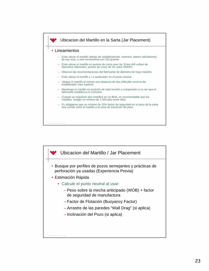
23
© 2007 Weatherford. All rights reserved.
Ubicacion del Martillo en la Sarta (Jar Placement)
• Lineamientos– Evite ubicar el martillo debajo de estabilizadores, reamers, wipers (aliviadores)
de key seat, u otra herramienta con OD grande
– Evite ubicar el martillo en puntos de cross-over (ej. Entre drill collars de diametros diferentes; puntos de cruce de DC para HWDP).
– Observe las recomendaciones del fabricante de diámetro de hoyo máximo
– Evite ubicar el martillo y / o acelerador en el punto neutral
– Ubique el martillo al menos una distancia de dos drillcollar encima del estabilizador mas superior
– Mantenga el martillo en posición de total tensión o compresión a no ser que el fabricante establezca lo contrario
– Cuando se requieren dos martillos en un BHA, es recomendable que los martillos tengan un mínimo de 1,500 pies entre ellos
– Es obligatorio que un mínimo de 15% factor de seguridad en el peso de la sartasea corrido entre el martillo y la zona de transición de peso
© 2007 Weatherford. All rights reserved.
Ubicacion del Martillo / Jar Placement
• Busque por perfiles de pozos semejantes y prácticas de perforación ya usadas (Experiencia Previa)
• Estimación Rápida• Calcule el punto neutral al usar:
– Peso sobre la mecha anticipado (WOB) + factor de seguridad de manufactura
– Factor de Flotación (Buoyancy Factor)– Arrastre de las paredes “Wall Drag” (si aplica)– Inclinación del Pozo (si aplica)

24
© 2007 Weatherford. All rights reserved.
Ubicacion del Martillo / Jar Placement
• Software de Ubicación del Martillo• Nota: Todos los programas son diferentes. Cada programa es encaminado para sus
propios productos y especificaciones
Información General : Vea la Hoja de Colectar la Información
Resultados del Computador– Tabla de la Sarta– Especificaciones del Martillo– Punto Neutral– Lectura de Indicador de Peso– Caracteristicas del Martillado
• Desplazamiento de la Sarta• Fuerzas de Impacto• Duración
© 2007 Weatherford. All rights reserved.
• Efecto de bomba• El martillo no dispara arriba• El martillo no dispara abajo• El martillo dispara mientras viaja• Goteo de aceite y grasa
Problemas de desempeno del Martillo

25
© 2007 Weatherford. All rights reserved.
• Atascado por encima del martillo• Efecto de bomba• Efecto de arrastre• Tiempo para disparo• Ciclo del martillo
El Martillo No Dispara
© 2007 Weatherford. All rights reserved.
• Prueba de entrada / Incoming test• Desarmado• Limpieza• Inspección de particulas magnéticas• Ensamblado• Prueba de sellos de presión• Prueba de funcionamiento / Blowing test
Mantenimiento del Jar y el Slinger

26
© 2007 Weatherford. All rights reserved.
• Especificaciones de Desempeño Máximas
Especificaciones Operativas del Martillo y el Slinger
© 2007 Weatherford. All rights reserved.
• Especificaciones de Desempeño Máximas
Especificaciones Operativas del Martillo y el Slinger

Dailey® Hydraulic Drilling Jar
Drilling Tools
Weatherford International Ltd.515 Post Oak Blvd., Suite 600Houston, Texas 77027 USATel: 713-693-4000weatherford.com
© 2008 Weatherford. All rights reserved. 170.05
Weatherford’s Dailey hydraulic drilling jar (HDJ) is a double-acting hydraulic jar designed for simple operation, variable hitting loads, and extended periods of continuous jarring in a wide range of drilling conditions. Using a patented hydraulic time-delay/mechanical-release system, the HDJ combines downhole reliability and long operating life under a wide range of drilling conditions and hostile environments.
Applications
High-angle drillstrings•All conventional oil and gas wells•Deviated oil and gas wells•
The one-piece involute spline mandrel provides maximum torque with minimal backlash •to ensure effective transfer of drillstring torque through the HDJ. Full torque in either direction can be transmitted at all times without affecting the magnitude or the time delay of the jarring operation. The splines and all other working parts of the tool are enclosed within the hydraulic chamber, where they are fully protected and lubricated.Afluid-isolated,high-pressurechamberlubricatesandisolatestheHDJ’smoving•seals, impact shoulders, and mandrel from downhole debris, protecting the HDJ’s operational integrity.The HDJ is virtually unaffected by downhole temperatures and generates very little •heat when in use. The result is a consistent time delay to trip the HDJ, even in deep, high-temperature holes. The design of this tool allows for zero bleed-off during jarring; therefore the driller •does not have to apply any compensation to the brake load. Overpull is controlled at the surface, enabling the driller to increase or decrease the •impact to the stuck point by simply increasing or decreasing the load applied to the jar.The hydraulic metering mechanism of the HDJ has no moving parts; it incorporates •largeflowpathsandisprotectedfromcontamination.Recocking is fast with a return to neutral and jarring again in either direction.•All connections are torqued to the charted makeup torque to ensure no accidental •back-offs downhole.
Features, Advantages and Benefits

Dailey® Hydraulic Drilling Jar
Drilling Tools
Weatherford International Ltd.515 Post Oak Blvd., Suite 600Houston, Texas 77027 USATel: 713-693-4000weatherford.com
© 2008 Weatherford. All rights reserved. 170.05
Specifications
OD (in./mm) 4-3/4120.65
4-3/4120.65
6-1/4158.75
6-1/2165.10
7177.80
7-3/4196.85
8203.20
9-1/2241.30
ID (in./mm) 2-1/1652.39
2-1/457.15
2-1/457.15
2-3/469.85
2-3/469.85
376.20
376.20
376.20
Tool joint size (API) NC-38, 3-1/2 IF
NC-38, 3-1/2 IF
NC-46, 4-1/2 XH
NC-50, 4-1/2 IF
5-1/2 FH
6-5/8 Reg.
6-5/8 Reg.
7-5/8 Reg.
Tensile yield* (lbf/kN)
436,000 1,939
500,000 2,224
832,000 3,701
934,000 4,155
1,200,000 5,338
1,600,000 7,117
1,750,000 7,784
2,300,000 10,231
Torsional yield* (lbf-ft/kN•m)
21,200 28.7
20,000 27.1
49,300 66.8
56,200 76.2
76,400 103.6
76,400 103.6
105,000 142.4
160,000 216.9
Maximum overpull up/down (lbf/kN)
95,000 423
85,000 378
200,000 890
175,000 778
220,000 979
260,000 1,157
300,000 1,334
500,000 2,224
Approximate length extended (ft/m)
32 9.8
32 9.8
33 10.1
33 10.1
33 10.1
33 10.1
33 10.1
33 10.1
Approximate weight (lb/kg)
1,200 544
1,200 544
2,050 930
2,400 1,089
3,000 1,361
3,500 1,588
3,800 1,724
5,500 2,495
Free-travel up/down stroke (in./mm)
5.00 127
5.50 140
6.25 159
6.50 165
6.50 165
7.00 178
7.00 178
7.00 178
Total stroke (in./mm) 13.50 343
15.00 381
16.50 419
17.00 432
17.00 432
19.50 495
19.50 495
19.50 495
Maximum bottomhole temperature (°F/°C)
400 204
Pump-open area (in.2/cm2) 9.6 61.9
10.3 66.5
15.9 102.6
19.6 126.5
23.8 153.5
28.3 182.6
28.3 182.6
38.5 248.4
* Tensile and torsional yield values are calculated per API RP7G, based on nominal dimensions and the published yield strength of the material and do not constitute a guarantee, actual or implied.

Dailey® Hydraulic Drilling Jar
Drilling Tools
Weatherford International Ltd.515 Post Oak Blvd., Suite 600Houston, Texas 77027 USATel: 713-693-4000weatherford.com
© 2008 Weatherford. All rights reserved. 170.05
Pump-Open Force Chart
Differential Pressure (psi/bar)
Pum
p-O
pen
Forc
es (1
,000
lbf/kN
)
0 40028
80055
1,20083
1,600110
2,000138
2,400165
2,800193
0
1044
2089
30133
50222
40178
60267
70311
80356
90400
100445
110489
120534
130578
9 1/2-in. OD241.30-mm OD
8- and 7 3/4-in. OD203.20- and 196.85-mm OD
7-in. OD177.80-mm OD
6 1/2-in. OD165.10-mm OD
6 1/4-in. OD158.75-mm OD
4 3/4-in. OD Big Bore120.65-mm OD Big Bore4 3/4-in. OD Standard120.65-mm OD Standard
Pump-open force is created by pressure drop across the bit. The pump pressure creates a reaction force in the tool that tries to force it open. Reduce the pump to idle before attempting to jar.

Dailey® Hydraulic Drilling Jar
Drilling Tools
Weatherford International Ltd.515 Post Oak Blvd., Suite 600Houston, Texas 77027 USATel: 713-693-4000weatherford.com
© 2008 Weatherford. All rights reserved. 170.05
During jarring, the mandrels move in response to the push/pull load applied at the surface, while the housings remain stationary. The movement of the mandrels, in either direction, is resisted by two pressure pistonsthatopposeeachothertodefineahigh-pressurechamber.Locatedbetweenthetwopressurepistons is a normally closed “triggering” valve (consisting of upper and lower valve halves) which controls thereleasingoffluidfromthepressurechamber.
The separate functions of jarring upward or downward may be accomplished in any sequence; that is, up only, down only, or up and down.
For jarring upward, the lower pressure piston moves upward with the mandrels, while a shoulder in thehousingpreventstheupperpressurepistonfrommoving.Sufficientpressureisgeneratedbetweenthe pressure pistons to resist the applied load until the triggering valve is mechanically opened by an actuating device. The time delay (from when the load is applied until the triggering valve opens) is achieved by a hydraulic metering mechanism that controls the speed at which the lower pressure piston moves toward the upper pressure piston. The lower pressure piston must move a predetermined distance before the actuating devices contact their respective valve halves and force the triggering valve to open. Thebuilt-indelayisdesignedtoallowtheoperatorsufficienttimetopulltotherequiredloadbeforethetriggering valve opens.
Whenthetriggeringvalveopens,thehigh-pressurefluidinthepressurechamberthatwasresistingtheoverpull is released from the high-pressure chamber to the hydrostatic pressure chamber; there being no further resistance to motion of the mandrel relative to the housing, the jar travels until the hammer impacts the anvil. For jarring upward again, the tool is returned to neutral by lowering the drillstring and then applying another up-load. This action may be repeated as often as necessary.
For jarring downward, a similar but opposite action occurs; that is, the upper pressure piston moves down with the mandrels in response to the weight applied from the drillstring above, while a shoulder on the housings prevents the lower pressure piston from moving. In down-jarring, triggering occurs when the upper pressurepistonhasmovedsufficientlytowardthelowerpressurepistontoforceopenthetriggeringvalve.
The HJ jar can be teamed with Weatherford’s MA drilling impact enhancer to increase the acceleration of the hammer mass for greater impacts.
Picking Up
Always use a lift sub to pick up the HDJ and a thread protector on the pin thread.
Caution: Do not tong any place on the HDJ except the top and bottom rotary connections. All service connections are pre-torqued before delivery. Placing tongs anywhere other than the top or bottom rotary connection could result in equipment damage.
Operation

Dailey® Hydraulic Drilling Jar
Drilling Tools
Weatherford International Ltd.515 Post Oak Blvd., Suite 600Houston, Texas 77027 USATel: 713-693-4000weatherford.com
© 2008 Weatherford. All rights reserved. 170.05
Removing and Installing the Mandrel Clamp
TheHDJarrivesonlocationwithahingedmandrelclamp(dogcollar)installed.Leavethemandrelclamp installed until the HDJ is ready to go through the rotary to protect the exposed section of the mandrel and prevent unintentional operation of the tool.
Caution: Do not tong on the exposed section of the mandrel or place this surface in the slips. Either action could result in equipment damage.
Caution: Do not attempt to remove the mandrel clamp unless the HDJ is in tension. Doing so could result in equipment damage.
To remove the mandrel clamp:
Pick up the weight from the slips to put the HDJ in tension.1. Remove the shipping strap, and pull the lock pin up until the U-shaped latch can be opened.2. Spread the two body halves, and remove the clamp from the HDJ.3.
Keep the clamp on location to be used when the tool is racked back.
To reinstall the mandrel clamp:
1. Visually inspect all parts for cracks or breakage.
Caution: Do not use the clamp if it is damaged or cannot be operated as described. Serious injury can result.
2. Install the clamp on the HDJ in tension and with the lock pin end up. The latch spring should return the latch to the closed position.
3. Push the lock pin down until the pin head engages the lug. The bottom of the pin can be seen protruding through the lower lug, and the latch is closed when the lock pin is fully seated.
4. Install the shipping strap around the clamp.
If the clamp cannot be used, either rack back jar as a single or lay it down.
Operation (continued)

Dailey® Hydraulic Drilling Jar
Drilling Tools
Weatherford International Ltd.515 Post Oak Blvd., Suite 600Houston, Texas 77027 USATel: 713-693-4000weatherford.com
© 2008 Weatherford. All rights reserved. 170.05
Opening the HDJ above the Rotary
Should the HDJ become cocked [9 in. (228.6 mm) of polished mandrel exposed] on the surface, it can easily be triggered open with a slight overpull.
1. Support the weight below the HDJ either in the slips or by closing rams on the bottomhole assembly.
Caution: If supporting weight in the slips, always ensure that the dog collar is attached to the HDJ to ensure that tool cannot fall downhole during the following procedure.
Caution: Place the slips only on the designated areas to avoid damaging it.
2. Pick up 5,000 to 10,000 lbf (22.2 to 44.5 kN) with the elevators. At this extremely low load, about 5 minutes will be required for the HDJ to trigger. With the HDJ fully extended, about 17 in. (432 mm) of polished mandrel will be exposed.
Placing the HDJ in the String
The HDJ can be run in tension or compression. Running a minimum 15% safety factor in string weight between the HDJ and the weight transition zone is mandatory. Run the same size drill collar or heavy-wall drillpipe directly above and directly below the HDJ.
Caution: Never run the HDJ as a crossover between the drill collars and the heavy-wall pipe or between the collars of different ODs; excessive stress occurs at these transition points and can lead to premature tool failure.
Important: Avoid running the HDJ below reamers, stabilizers, key-seat wipers, or any other tool with an OD that exceeds that of the HDJ. Doing so can restrict the jarring function.
Caution: Never run the HDJ in close proximity to another HDJ or any other type of jar. Doing so can impose excessive loads during jarring operations, resulting in equipment damage. Maintain a minimum distance of 1,500 ft (500 m) between jars.
Operation (continued)

Dailey® Hydraulic Drilling Jar
Drilling Tools
Weatherford International Ltd.515 Post Oak Blvd., Suite 600Houston, Texas 77027 USATel: 713-693-4000weatherford.com
© 2008 Weatherford. All rights reserved. 170.05
Drilling with the HDJ in Compression
The HDJ is normally in tension when the bit reaches the bottom and should be triggered down with a light loadtoclosethetoolandpreventthetransmissionofsignificantimpactforcesfromthetool.
The HDJ will cock when the string is picked up off the bottom; therefore, this procedure should be followed each time a connection is made.
Important: Pressure differential between the drillpipe ID and the annulus at the jar will tend to pump open the tool, which, during normal drilling, will have no effect on either the weight on the bit or the HDJ itself. If the HDJ is in tension while drilling, this pump-open force only tends to keep the jar extended. Pump-open force increases the up-jar load and decreases the down-jar load. To calculate pump-open force, multiply thepump-openarea(see“Specifications”)bythepressuredropacrossthedrillbittodeterminethechange in weight indicator reading. (See also Pump Open Force chart.)
Running In
Use care to start and stop slowly when running in to avoid repeatedly opening and closing the tool, which could cause the HDJ to cock. Run through tight spots and doglegs slowly. Be aware that anything that restrictstheIDofthepipeordrillcollarsbelowtheHDJ(floatvalves,surveytools,etc.)cancausethedrillcollarsto“float”ifthepipeisloweredtoorapidlyandcanresultincockingtheHDJ.
If it is suspected that the HDJ has inadvertently recocked during run-in or on bottom, suspend the drillpipe in the elevator long enough for the HDJ to trip open (from the weight of the drill collars suspended below it). If it appears that the HDJ has inadvertently recocked at the surface, it can easily be tripped open with as little as 5,000 lbf (22.2 kN). At this extremely low load, about 5 minutes is required for the jar to trip.
Operation (continued)

Dailey® Hydraulic Drilling Jar
Drilling Tools
Weatherford International Ltd.515 Post Oak Blvd., Suite 600Houston, Texas 77027 USATel: 713-693-4000weatherford.com
© 2008 Weatherford. All rights reserved. 170.05
Jarring
No presetting or adjustment is required before running or jarring. The HDJ is controlled completely from the surface, using only axial motion.1. Pull up to the required load. Wait a few seconds for the HDJ to jar up; or slack off to the required load,
and wait for the HDJ to jar down.Note: For a stronger impact, pull harder; for a lesser impact, pull more lightly. No other action is required of the operator, and the HDJ can be hit in any sequence (up only, down only, or up and down).The waiting time between setting the brake and the jarring action will be in the range of 10 to 120 sec, depending on applied load, and will not be affected by changes in downhole temperature or hydrostatic pressure or the number of times the HDJ is actuated. It is never necessary to “warm up” the HDJ or to circulate to “cool off” the HDJ.Drilling does not affect the HDJ. Full torque in either direction can be transmitted at all times without affecting either the magnitude or the time delay of the jarring action.
2. After impact, return the HDJ to neutral with motion in the opposite direction until resistance is met. The HDJ will immediately be ready to jar in the same or the opposite direction.Note: It is not necessary to slack off (or pull up, if jarring down) an exact amount of weight or to control thetraveloftheHDJtorecock.Thepropertraveloccursautomaticallyifsufficientweightisslackedoff(or pulled up) to allow the necessary travel at the tool.When the HDJ is recocked to jar again in the same direction, the time delay of the next blow is not affected by overtravel in the direction of neutral.
Operation (continued)
Example: Upward Jarring Jar
Slack off from 200,000 to 190,000 lbf (890 to 845 kN) to recock the jar.
Example: Downward Jarring Jar
Slack off from 220,000 to 240,000 lbf (979 to 1,068 kN) to recock the jar.
(lbf) (kN)Total string weight 250,000 1,112Weight below jar - 40,000 - 178Weight above jar 210,000 934Jar setting for jarring up + 92,000 + 409 302,000 1,343Hole drag + 20,000 + 89Indicator reading to trip jar upward 322,000 1,432
(lbf) (kN)Total string weight 250,000 1,112Weight below jar - 40,000 - 178Weight above jar 210,000 934Jar setting for jarring down - 37,000 - 165 173,000 769Hole drag - 20,000 - 89Indicator reading to trip jar upward 153,000 680

Dailey® Hydraulic Drilling Jar
Drilling Tools
Weatherford International Ltd.515 Post Oak Blvd., Suite 600Houston, Texas 77027 USATel: 713-693-4000weatherford.com
Weatherford products and services are subject to the Company’s standard terms and conditions, available on request or at weatherford.com. For more information contact an authorized Weatherford representative. Unless noted otherwise,trademarksandservicemarkshereinarethepropertyofWeatherford.Specificationsaresubjecttochangewithout notice. Weatherford sells its products and services in accordance with the terms and conditions set forth in the applicable contract between Weatherford and the client.
© 2008 Weatherford. All rights reserved. 170.05
Pulling Pipe
Exercise caution when pulling pipe to eliminate any danger associated with the HDJ inadvertently tripping, which can occur if the HDJ is unexpectedly in compression when the bit is lifted off bottom. To guard against inadvertent tripping, allow the pipe to hang off bottom long enough for the HDJ to trip through (as a result of the action of the load hanging below it) before suspending the pipe from the slips.
Racking Back
When the HDJ comes through the rotary, install the mandrel clamp while the tool is still in tension.
Caution:DonotstandtheHDJintherackunlessthemandrelclampisfitted.Doingsocaninitiateunintentional operation of the tool and pose a safety hazard.
Maintaining the HDJ
Take the following steps each trip out of the hole:
Wash the mud from the polished mandrel and from inside the bottom connection. 1. Checkthepolishedmandrelcarefullyforanysignsofcorrosion,pitting,orflakingofthecoating.2. Replace the mandrel clamp while the HDJ is still in tension.3.
Operation (continued)

Basic Motor Information Houston, TX
1
1© 2005 Weatherford. All rights reserved.
Información Básica del Motor /Operación para los Perforadores DireccionalesBrian Hunt – Global DD Tools R&M ManagerCurtiss Rinehart – Global Fireman
June 30, 2008
2© 2005 Weatherford. All rights reserved.
Por que? POR QUE? PORQUE?
Por qué **** debo yo tomar este curso?
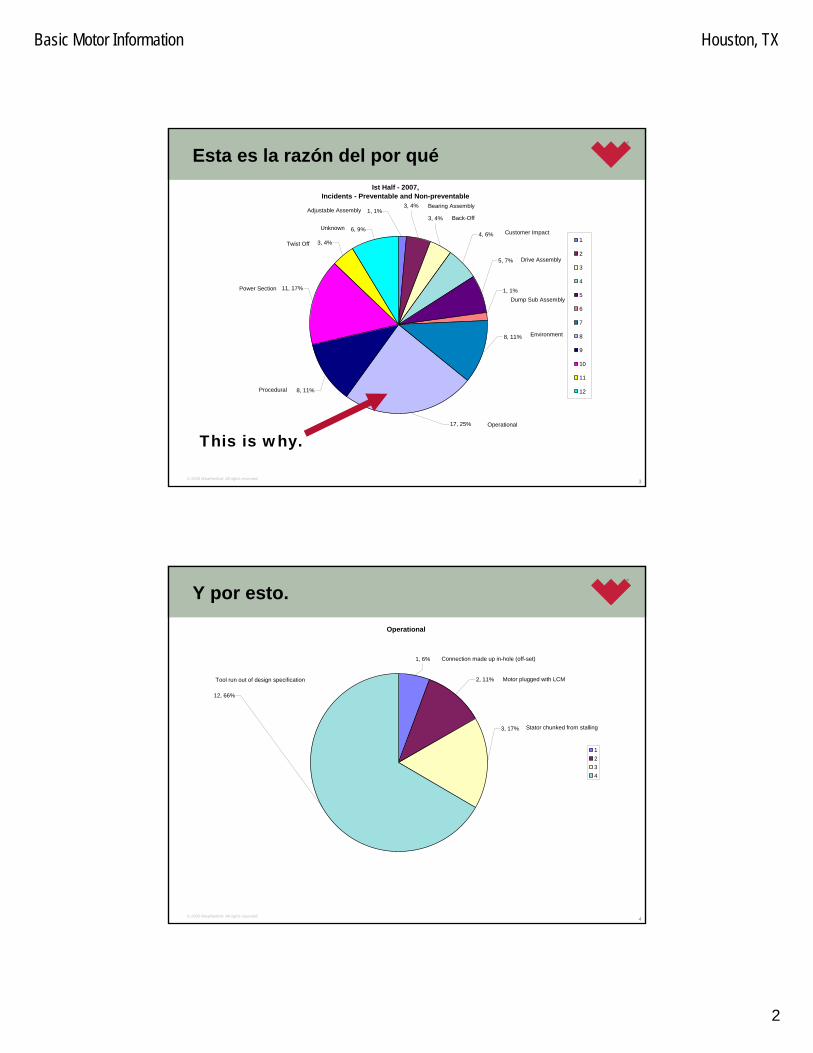
Basic Motor Information Houston, TX
2
3© 2005 Weatherford. All rights reserved.
Esta es la razón del por qué
This is why.
Ist Half - 2007, Incidents - Preventable and Non-preventable
17, 25%
8, 11%
1, 1%
5, 7%
4, 6%
11, 17%
8, 11%
3, 4%
6, 9%
1, 1%3, 4%
3, 4%
1
2
3
4
5
6
7
8
9
10
11
12
Adjustable AssemblyBearing Assembly
Back-Off
Customer Impact
Drive Assembly
Dump Sub Assembly
Environment
Operational
Procedural
Power Section
Twist Off
Unknown
4© 2005 Weatherford. All rights reserved.
Y por esto.
Operational
1, 6%
2, 11%
3, 17%
12, 66%
1234
Connection made up in-hole (off-set)
Motor plugged with LCM
Stator chunked from stalling
Tool run out of design specification

Basic Motor Information Houston, TX
3
5© 2005 Weatherford. All rights reserved.
Y esto también.
Procedure
3, 37%
1, 13%1, 13%
2, 24%
1, 13%
12345
Design defect
Failed to follow standard procedures
Incorrect tool sent to field
Part installed incorrectly
Part missed in assembly
6© 2005 Weatherford. All rights reserved.
Y esto.
Power Section
5, 46%
2, 18%
2, 18%
2, 18%
1234
Motor weak after use
Stator chunked (not from Environment or stalling)
Stator Debonded
Stator ribbed/work

Basic Motor Information Houston, TX
4
7© 2005 Weatherford. All rights reserved.
Esta es la fria y dura verdad:
25%todos los incidentes fueron operacionales.
66%de estos fueron por herramientas que fueron corridas
fueras de sus especificaciones.
(Data del 2007.)
8© 2005 Weatherford. All rights reserved.
Proposito de un Motor
Qué es lo que un motor de perforación hace para la exploración de petroleo & gas?

Basic Motor Information Houston, TX
5
9© 2005 Weatherford. All rights reserved.
10© 2005 Weatherford. All rights reserved.
APLICACIONES
• La versatilidad y la variedad de los motores de perforaciónPrecisionDrill™ le permiten ser usados para una cantidadde dierentes aplicaciones de fondo. Como la variedad de los diseños se expande, el número de aplicaciones en lasque el motor PrecisionDrill™ puede operar tambiéncrecerá.

Basic Motor Information Houston, TX
6
11© 2005 Weatherford. All rights reserved.
APLICACIONES
• PERFORMANCE DRILLING/ Perforación de desempeño
• Los motores PrecisionDrill™ pueden ser usados paraaumento de desempeño en la perforación. La ampliavariedad de torque, velocidad, y capacidad en tasa de flujode los motores de fondo nuestros se presta facilmentepara un gran rango de tipos de mechas de perforación y condiciones de la formacion. La perforación Rotaria (mesa de rotación) puede además ser aplicada en adición a la rotación generada en el motor de fondo para el incrementoen la velocidad de la mecha como requerido. Se suministra poder directamente a la mecha, reduciendo el desagaste y el esfuerzo en los componentes de la sarta, e incrementando sustancialmente la vida util de estos.
12© 2005 Weatherford. All rights reserved.
APLICACIONES
• DIRECTIONAL DRILLING/ Perforación Direccional• La Perforación Direccional se inició como una operación
remedial para resolver un problema de la perforación; usualmente debido a un pescado o escobros dejadoshoyo abajo. Hoy dia, con la creación de requerimientoslegales de espacio y localización, la mejora en el modelajede ingenieria de yacimientos, y la perforación de multiples pozos desde una localizacion simple en superficie, se ha convertido en una muy importante actividad para tantocontrolar el posicionamiento de la hoyo durante la perforación y para relacionar esta a la posicion de otroshoyos y pozos existentes y a los limites fronterizos de la concesión

Basic Motor Information Houston, TX
7
13© 2005 Weatherford. All rights reserved.
APLICACIONES
• DIRECTIONAL DRILLING/ Perforación Direccional• La aplicación más obvia para la perforación direccional es
para areas inaccessibles para las técnicas de perforaciónvertical convencional. Cuando de se perfora hacia el yacimiento debajo de montañas, agua (rios, lagos o mar), ciudades, o areas de sensibilidad medio ambiental, los pozos pueden ser controlados direccionalmente paraalcanzar los objetivos subterraneos requeridos. Cuando el yacimiento esta cerca de formaciones problemáticas(como formaciones de sal (domos), fallas (steep fault planes), etc.) las técnicas de perforación direccionalpueden ser usadas para evitar estas y minimizar su efectoen los procesos de perforación y recuperación.
14© 2005 Weatherford. All rights reserved.
APLICACIONES
• DIRECTIONAL DRILLING/ Perforación Direccional• Otra de las bondades con la perforación direccional es la
capacidad para perforar multiples pozos desde una sola emplanada o desde un solo punto. Esto es valioso en los casos de los taladros y plataformas de perforación costaafuera los que requieren una inversión significante de tiempo y dinero. Multiples pozos pueden ser perforadosdesde un solo punto hacia varios targets para la optimización de la recoperación (producción), reduciendoel tiempo de taladro y los costos operacionales.

Basic Motor Information Houston, TX
8
15© 2005 Weatherford. All rights reserved.
APLICACIONES
• DIRECTIONAL DRILLING/ Perforación Direccional• La Perforación Direccional puede también ser usada para
perforar pozos de alivio (relief wells). En situacionesdonde un pozo se vuelve incontrolable (blow out/arremetida), un pozo de alivio es perforado paraintersectar el hoyo original para que se pueda bombear un lodo pesado a travez del pozo de alivio para matar ( “kill” ) el pozo descontrolado (hoyo original).
16© 2005 Weatherford. All rights reserved.
APLICACIONES
• HORIZONTAL DRILLING & WELL RE-ENTRY / Perforación Horizontal y Pozos de Re-entrada
• En ciertos yacimientos, la recuperación puede ser dramaticamente mejorada al perforar directionalmente un pozo horizontalmente (mas de 80º de inclinación) por un largo extendido. A mayor exposición del reservorio mayor será la tasa de producción equivalente de drenaje .

Basic Motor Information Houston, TX
9
17© 2005 Weatherford. All rights reserved.
APLICACIONES
• HORIZONTAL DRILLING & WELL RE-ENTRY / Perforación Horizontal y Pozos de Re-entrada
• Tipicamente, la sección de construcción de un pozo esperforada con un motor de fondo grande y el revestidor/casing es corrido hasta el comienzo de la sección horizontal. Esta sarta de revestidor asegura la integridad del hoyo cuando la sección horizontal esperforada. La sección de construcción puede ser perforada con una variedad de tasas desde radios largos hasta radios cortos. Las tasas de construcción dependende las condiciones del hoyo, requerimientos de lasdimensiones de la horizontal, y de la economía del pozo.
18© 2005 Weatherford. All rights reserved.
APLICACIONES
• HORIZONTAL DRILLING & WELL RE-ENTRY/ Perforación Horizontal y Pozos de Re-entrada
• Un motor de fondo menor es entonces usado para perforarla sección horizontal del pozo. Si la componente horizontal del pozo será una recta, se recomienda que el motor de pequeño diametro se configure con bajo ángulo para la horizontal y sea rotado para el mantenimiento de la inclinación del hoyo. Si se requiere de algún ajuste, el pequeño bend/doblez en el motor de fondo puede ser usado para corregir la trayectoria del hoyo. Configuraciongrandes en el bend del motor han sido usadas paraperforar, produciendo giros agresivos en la lateral. Sin embargo, ello resulta en cargas de trabajo elevadas sobreel ensamblaje de fondo y cambios bruscos en la trayectoria horizontal, lo cuál es no deseable.

Basic Motor Information Houston, TX
10
19© 2005 Weatherford. All rights reserved.
APLICACIONES
• HORIZONTAL DRILLING & WELL RE-ENTRY / Perforación Horizontal y Pozos de Re-entrada
• Una extension de la perforación horizontal es la perforación de pozos multilaterales. Los pozosmultilaterales tienen mas de una seccion de hoyo lataralque emana desde un hoyo sencillo. Este puede ser en forma de varios pozos horizontales saliendo radialmentedesde un pozo vertical simple. Los pozos horizontalespueden estar en el mismo plano, o estar ubicadosestratégicamente en diferentes planos para multiples reservorios. Un segundo método es el desviar (sidetrack) desde un pozo horizontal existente para penetracion haciaotras areas en el reservorio para recuperación adicional.
20© 2005 Weatherford. All rights reserved.
APLICACIONES
• HORIZONTAL DRILLING & WELL RE-ENTRY / Perforación Horizontal y Pozos de Re-entrada
• En adición, a las técnicas ya vistas se puede usar tambiénpara realizar una re-entrada/re-entry. Los pozos existentesson regularemente re-entrados para recuperaciónadicional del yacimiento. El Desvio/Sidetracking puede ser realizado tanto en la sección de construcción como en la sección horizontal de un pozo existente para penetrarhacia areas aún no drenadas con el pozo original.

Basic Motor Information Houston, TX
11
21© 2005 Weatherford. All rights reserved.
APLICACIONES
• AIR / MISTED DRILLING ( Perforación aereada / bajobalance)
• Fluidos Comprimibles como el aire, nitrogeno, gas natural, etc., pueden ser usados en combinación con un fluidolubricante. Existen muchas ventajas para perforar con fluidos comprimibles. Mejora en la limpieza del hoyo, asicomo el aumento en la tasa de penetración y la reduccióndel tiempo de taladro y los costos. Los problemas de pérdida de circulación son eliminados, el daño a la formación es limitado, y es posible realizar una pruebacontinua de producción de las formaciones potenciales(drill stem testing).
22© 2005 Weatherford. All rights reserved.
APLICACIONES
• AIR / MISTED DRILLING ( Perforación aereada / bajobalance), continuación…
• Cuando se opera un motor de fondo PrecisionDrill™ con aire/gas/mescla, se deben tomar precauciones extras paraminimizar el desgaste y extender la vida util del motor. Se recomienda que una fase de fluido lubricante sea añadidaal sistema. Como se establece tempranamente, la interferencia entre el rotor y el estator crea una pequeñacavidad en todo su largo. Según esta cavidad se mueve a lo largo de la sección de poder por la rotación del rotor dentro del estator, el volumen de la cavidad se mantieneigual.

Basic Motor Information Houston, TX
12
23© 2005 Weatherford. All rights reserved.
APLICACIONES
• AIR / MISTED DRILLING ( Perforación aereada / bajobalance), continuación…
• Sin embargo, en este caso como existen cambios de presión en el air/gas según la cavidad progresa (lo cuáles requerido para generar el torque), el volumen debetambién cambiar. Como consecuencia, según la cavidadprogrese, la presion caerá para desarrollar el torque, y el volumen de air/gas se incrementará. Este aumento en el volumen de aire resulta en un escape o pérdida al final de la sección de poder en su extremo inferior lo quepotencialmente daña a el estator. ( Se conoce como blow-by en ingles)
24© 2005 Weatherford. All rights reserved.
APLICACIONES
• AIR / MISTED DRILLING ( Perforación aereada / bajobalance), continuación…
• El propósito del fluido de lubricación es para lubricar la superficie entre el rotor y el estator de la sección de poder, así como para proveer asistencia en el enfriamiento parareducir el daño al estator por el escape al final de la seccion (blow-by). Si la cantidad de fluido lubricante esdisminuida, el desgaste en la goma/elastomero aumenta, lo que reduce significamente la vida del motor de fondo.
Basic Motor Information Houston, TX
13
25© 2005 Weatherford. All rights reserved.
APLICACIONES
• AIR / MISTED DRILLING ( Perforación aereada / bajobalance), continuación…
• Cuando se opera un motor de fondo PrecisionDrill™ con air/gas, se debe tener cuidado de no dejar correrlibremente (sin carga) en ningun instante. Esto causaráque el rotor gire a tasas más allá de la que está diseñado, desgastandolo prematuramente. Cuando vaya a comenzara perforar con el motor, algun peso sobre la mecha debeser aplicado antes de estabilizar el flujo totalmente a la tasa requerida por la perforación. Esto proveerá un pocode resistencia al rotor en el estator y prevenirá que este se sobre-acelere girando.
26© 2005 Weatherford. All rights reserved.
APLICACIONES
• AIR / MISTED DRILLING ( Perforación aereada / bajobalance), continuación…
• Similarmente, cuando pare la perforación, un poco de peso sobre la mecha debe ser mantenido hasta que no exista caida de presión a travéz del motor. Alternativamente, la tasa de flujo total debe ser reducidaen su totalidad cuando este fuera de fondo (off-bottom) para reducir las RPM y la vibración creada. Una vez en fondo (on-bottom), el flujo puede ser aumentado hastaalcanzar las tasas requeridas. El no seguimiento de esteprocedimiento causará el daño prematuro en el estator, asicomo la posible causa de una fractura interna en lasuniones o un desenrosque.

Basic Motor Information Houston, TX
14
27© 2005 Weatherford. All rights reserved.
APLICACIONES
• AIR / MISTED DRILLING ( Perforación aereada / bajobalance), continuación…
• El represionamiento/estolamiento (Stalling) del motor puede rapidamente causar un desgaste extensivo en el estator. Cuando el represionamiento ocurre, el rotor se sella junto con el estator, causando que la presión de air dentro de la sarta aumente gradualmente. Cuando el motor de fondo es levantado, el sello entre el rotor y el estator cede, y el air pasa a travez de este. Sin embargo, ya que la presión es mayor, y la tasa de flujo se ha incrementado más allá de la capacidad de la sección de poder, el rotor girará sobre el limite permisible y el estatorse desgastará en poco tiempo.
28© 2005 Weatherford. All rights reserved.
APPLICATIONS
• AIR / MISTED DRILLING ( Perforación aereada / bajobalance), continuación…
• Cuando el represionamiento sucede, no es facil de identificar como un incremento de la presión en superficie. Como el medio de perforación es comprimible, el represionamiento no se va a notar inmediatamente. Poreso, la ROP debe ser usada como indicador de un represionamiento. Si la ROP cae excesivamente, estodebe ser considerado como un indicativo de que el motor de fondo se esta represionando o estolando.

Basic Motor Information Houston, TX
15
29© 2005 Weatherford. All rights reserved.
APLICACIONES
• AIR / MISTED DRILLING ( Perforación aereada / bajobalance), continuación…
• Otra preocupacion que surge cuando se usa un fluidocompresible como poder para el motor de fondo es la decompresión explosiva. Esto es especialmente en casode uso de gas nitrógeno. Cuando un motor de fondo esoperado en el fondo, el gas penetra en los poros de los componentes elastomericos. La cantidad de gases quepenetran la goma se incrementa por la alta presion queesta siendo aplicada y por los largos periodos en uso. Sin embargo, esta absorcion inicial de gases no afecta el desempeño del motor. Una vez que el motor es sacadodel hoyo, la presión sobre los componentes de gomadecrece enormemente, permitiendo a los gases expandirse y crecer dentro de la goma.
30© 2005 Weatherford. All rights reserved.
APLICACIONES
• AIR / MISTED DRILLING ( Perforación aereada / bajobalance), continuación…
• Esto provaca el hinchamiento de la goma, y el posibledaño total, afectando la integridad del drilling motor.
• En pozos donde se expera usar el motor bajo un cambiode presiones por encima de 10,000 kPa (1450 psi), la descompresion explosiva es posible cuando se saca de fondo. Para minimizar este efecto, la tasa de velocidad a la cual el motor es sacado del hoyo debe ser reducidapara permitir el tiempo para que el gas nitrogenopermeado escape de la gome del motor sin causar el hinchamiento.

Basic Motor Information Houston, TX
16
31© 2005 Weatherford. All rights reserved.
APLICACIONES
• AIR / MISTED DRILLING ( Perforación aereada / bajobalance), continuación…
• En pozos donde el motor pudo estar expuesto a estacondicion, se recomienda que no sea usado y se envie a inspección. Una vez más, no es la presión en el motor la que causa la decompresion explosiva, sino la tasa de caida de presion a la que la goma es expuesta. En el fondo, el gas que ya esta comprimido dentro de la goma, no la deforma. El Daño no sucede hasta que la presión en la goma cae dramáticamente por más de 10,000 kPa(1450 psi).
32© 2005 Weatherford. All rights reserved.
APLICACIONES
• AIR / MISTED DRILLING ( Perforación aereada / bajobalance), continuación…
• Cuando se perfora con aire, el puerto de descarga del ensamble de dump sub debe estar taponado (plugged off) (o el dump sub debe ser reemplazado con un top sub). La caida de presión a travéz del dump sub no debe ser lo suficiente para cerrarse bajo tasas de flujo de aire/gas.

Basic Motor Information Houston, TX
17
33© 2005 Weatherford. All rights reserved.
APLICACIONES
• AIR / MISTED DRILLING ( Perforación aereada / bajobalance), continuación…
• Se recomienda que antes de la perforación con aire/gas el departamento Técnico de Weatherford Drilling Services revice la información del pozo con un modelo paraproveer una combinación de tasa de flujo y tasa de fluidolubricante sugerida. Con todos los fluidos comprimibles, el desempeño de los motores de fondo de PrecisionDrill™varian grandemente con la pequeña diferencia en estasdos tasas de flujo. Para proveer una vida optima y unaapropiada desempeño, se sugiere que un equipoprofesional de Weatherford le asista con la selección de las tasas de flujo.
34© 2005 Weatherford. All rights reserved.
APLICACIONES
• DESEMPEÑO DEL MOTOR BAJO FLUJO BI-FASICO • El desempeño del Estator de un motor de desplazamiento
positivo (PDM) usado en perforación bajo balance se afecta significativamente por la tasa de flujo, el tipo de fluido y la lubricación provista por el fluido de perforación. Algunos test de desempeño han sido conducidos con los motores de fondo bajo condiciones de flujo bi-fasicorevelando algunos comportamientos interesantes.

Basic Motor Information Houston, TX
18
35© 2005 Weatherford. All rights reserved.
APLICACIONES
• DESEMPEÑO DEL MOTOR BAJO FLUJO BI-FASICO• Algunos trabajos han sido publicados presentando ideas
en como escojer un motor mediante indicadores de desempeño o en banco de prueba. Estas pruebas y lasdiscusiones son utiles en el entendimiento de laslimitaciones del PDMs en condiciones de flujo bifásico.
• Esto es importante para comprender como el desempeñode un PDM es afectado por pequenos cambios en los parametros operacionales cuando se trata de mejorar el desempeño en un medio de flujo bifásico
36© 2005 Weatherford. All rights reserved.
APLICACIONES
• DESEMPEÑO DEL MOTOR BAJO FLUJO BI-FASICO• El motor es ligeramente sobre usado cuando se circula la
sarta fuera de fondo.• Cuando se perfora en el fondo, un aumento en el flujo
equivalente combinado de 10% sobre el maximorecomendado puede ayudar a reducir los problemas de represionamiento.
• Permitir un PSM (WOB) para dejar de perforar (“drill off”) antes de sacar de fondo.
• Trabajar de cerca con el operador y el ingeniero de perforación bajo balance para hacer los pequeñoscambios de parámetros.

Basic Motor Information Houston, TX
19
37© 2005 Weatherford. All rights reserved.
APLICACIONES
• DESEMPEÑO DEL MOTOR BAJO FLUJO BI-FASICO• La siguiente es una lista de puntos a considerar cuando se
sospecha de algún problema con el motor de fondocuando se perfora con flujo bifásico:
• A mayor relación gas / liquido (menor tasa de liquido) másfácil se represionará el motor a pesar de que la tasacombinada de flujo equivalente este al máximo de la del motor rating. Un blow-by / pérdida en el estator (onset of stalling) ocurrirá pronto y a baja presión diferencial en flujo bifásico que un flujo sencillo.
• Bajar la tasa de la fase liquida puede causar bajalubricación resultando en tasas de desgaste grandes.
38© 2005 Weatherford. All rights reserved.
APLICACIONES
• DESEMPEÑO DEL MOTOR BAJO FLUJO BI-FASICO• La curva de desempeño del torque de un PDMs usado en
flujo bifásico no cambia significativamente, excepto que la presión diferencial maxima predictada no puede ser lograda antes de que el motor se represione bajando el máximo torque de salida.

Basic Motor Information Houston, TX
20
39© 2005 Weatherford. All rights reserved.
APLICACIONES
• DESEMPEÑO DEL MOTOR BAJO FLUJO BI-FASICO• El gráfico siguiente (proxima pagina) ilustra el
comportamiento tipico de un motor de 4-3/4” bajodiferentes condiciones de flujo pero con tasas de flujocombinadas equivalentes similares.
Note la baja significante en la RPM con la misma presióndiferencial. Esta caida en la RPM combinada con la producción del reservorio y el grado de desbalanceobtenido (cuanto se encuentra por debajo de la presióndel reservorio), pueden tener un efecto significante en la tasa de penetración.
40© 2005 Weatherford. All rights reserved.
RPM versus Presión Diferencial en un Flujo Bi-Fase— 4 3/4” (121 mm) PrecisionDrill™ LN7822-ML.
������������� ����� �����������������������
����� ��!�"��# ���$ ���%#��
#%
���
���
���
���
��
��
��
��
�� ��� �� ��� ��� �� ��� ��� ���
"
&
�
�
�
�� ��������������� ����������� ��������
��������� !���������� !�������"������� !��������#������ !�������$�����%&���&�'������ !�������

Basic Motor Information Houston, TX
21
41© 2005 Weatherford. All rights reserved.
APLICACIONES ESPECIALES
• Los motores de fondo PrecisionDrill™ han sido usadospara perforar hoyos ductos para acomodar cables de pipelines, y otros medios de transmision. Estos hoyos son generalmente perforados para atravesar obstaculos en el camino propuesto que representa un problema en los metodos convencionales de trinchera; cruce de rios, elevaciones pronunciadas o terrenos inestables, aproximaciones costeras, o areas de sensibilidad medioambiental.
42© 2005 Weatherford. All rights reserved.
APLICACIONES ESPECIALES
• Extracción de minerales solubles en agua (como son: sal, potash/ carbonato de potasio o oxido de potasio) quepueden ser obtenidos por medio de tecnologia de mineriade disolución. En esta práctica, se perforan una “pareja”de pozos en el objetivo predeterminado y se hace circular agua a travéz de los hoyos hasta que se establece un comunicación entre ellos. El agua es entonces forzadahacia abajo por un pozo y se retorna a superficie por el otro con el mineral en solución.
Basic Motor Information Houston, TX
22
43© 2005 Weatherford. All rights reserved.
APLICACIONES ESPECIALES
• Grout holes/ Hoyos finos (poco diametro) para rellenopueden ser perforados para estabilizar formaciones pococonsolidadas o para aislar formaciones contenedoras de agua. Su apropiado emplazamiento y su control resultaránen reducción de costos totales y mejora en la eficienciatécnica de este procedimiento.
44© 2005 Weatherford. All rights reserved.
APLICACIONES ESPECIALES
• Los hoyos para drenaje de Metano y Agua son comunesen la industria minera por años. Técnicas similares hansido empleadas en la industria medio ambiental para la evacuación in-situ de contaminantes tóxicos dejados en sitios de disposición de residuos industriales.

Basic Motor Information Houston, TX
23
45© 2005 Weatherford. All rights reserved.
Propósito de un Motor de Fondo
Principios Generales de Como Trabaja el Motor en el Fondo
46© 2005 Weatherford. All rights reserved.
Propósito de un Motor de Fondo

Basic Motor Information Houston, TX
24
47© 2005 Weatherford. All rights reserved.
Propósito de un Motor de Fondo
48© 2005 Weatherford. All rights reserved.
Componentes
Los motores de perforación PrecisionDrill™ consistenmayormente por los siguientes ensambles:
• Top Sub / Dump Sub• Rotor Catch• Power Section• Drive Ensamble• Ensamble Ajustable• Mud Lubricated Bearing Section
(Sección de Rodamientos) • Estabilización
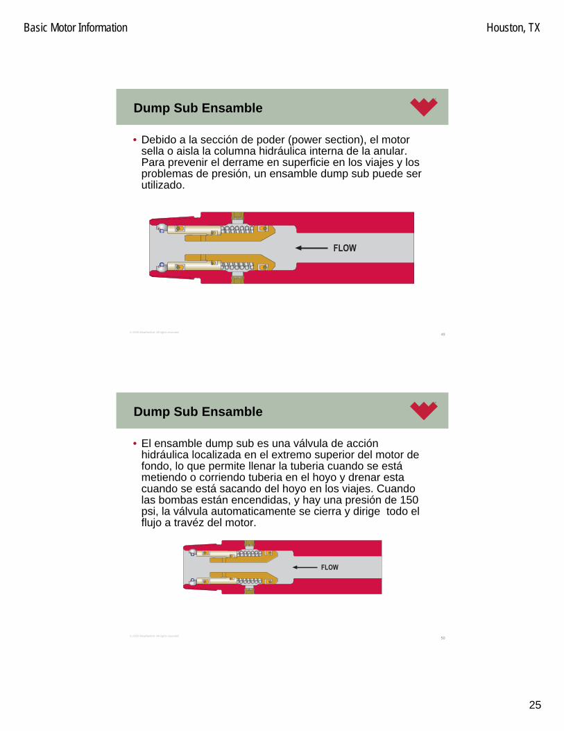
Basic Motor Information Houston, TX
25
49© 2005 Weatherford. All rights reserved.
Dump Sub Ensamble
• Debido a la sección de poder (power section), el motor sella o aisla la columna hidráulica interna de la anular. Para prevenir el derrame en superficie en los viajes y los problemas de presión, un ensamble dump sub puede ser utilizado.
����
50© 2005 Weatherford. All rights reserved.
Dump Sub Ensamble
• El ensamble dump sub es una válvula de acciónhidráulica localizada en el extremo superior del motor de fondo, lo que permite llenar la tuberia cuando se estámetiendo o corriendo tuberia en el hoyo y drenar estacuando se está sacando del hoyo en los viajes. Cuandolas bombas están encendidas, y hay una presión de 150 psi, la válvula automaticamente se cierra y dirige todo el flujo a travéz del motor.
����

Basic Motor Information Houston, TX
26
51© 2005 Weatherford. All rights reserved.
Dump Sub Ensamble
• En caso de que el ensamble dump sub no es requerido o deseado, como en perforación bajo balance usando gas nitrogeno o aire, este efecto puede ser eliminado al simplemente re-emplazar el orificio de descarga con un tapón ciego (4-3/4” y mayor). Esto permite al motor ser ajustado si se requiere aún en el campo. En todo caso, el dump subs puede ser re-emplazado por un top subs si se quiere.
����
52© 2005 Weatherford. All rights reserved.
Rotor Catches
• Los motores de fondo PrecisionDrill™ también vienen con un mecanismo de captura o retensión del rotor (rotor catch mechanism). En caso de que la connección desenrosqueo se parta, este elemento de seguridad va a prevenir quealguna parte del motor sea dejada en el hoyo.
Rotor Catch Mandrel Rotor Catch Plug

Basic Motor Information Houston, TX
27
53© 2005 Weatherford. All rights reserved.
Rotor Catches
• El catch mandrel está connectado al rotor del motor de fondo, y será retenido dentro del top-most sub del drilling motor, asegurando de que cuando el BHA sea sacado del hoyo este traiga el resto del motor consigo.
54© 2005 Weatherford. All rights reserved.
Rotor Catches
• Los motores PrecisionDrill™ y ComDrill™ vienen con el mechanismo de rotor catch disponible. En caso de que la connección desenrosque o se parta, este elemento de seguridad va a prevenir que alguna parte del motor sea dejada en el hoyo.

Basic Motor Information Houston, TX
28
55© 2005 Weatherford. All rights reserved.
Rotor Catch Haciendo su Función
• Esta figura muestra el esquema básico de comofunciona el mecanismo del rotor catch.
• El catch mandrel se connectaal rotor del drilling motor, y estese quedara retenido dentro del hombro interno de soporte del top-most sub del motor, asegurando que cuando el ensamble de fondo se levantedel hoyo traiga el resto del motor con el.
56© 2005 Weatherford. All rights reserved.
Rotor Catch Funcionando
• En caso de partidura o desenrosque en el fondo en el motor, el operator debe estar en capacidad de rapidamente identificar esto. La caracteristicareveladora de este evento es de que cuando el WOB es removido del motor, la presión en el standpipe debe aumentar. Si se vuelve a aplicarWOB, el aumento de presión desaparecerá.

Basic Motor Information Houston, TX
29
57© 2005 Weatherford. All rights reserved.
Rotor Catch Funcionando
• La naturaleza del diseño del rotor catch es tal que siuna partidura o desenrosque en el motor ha ocurridodesde entre el tope del Estator y el Ensemble Ajustable, la sarta es sacada del hoyo y la parte inferior restante del motor aún debe colgar del extremo de esta, el catch mandrel se sostendradentro del hombro interno de la camisa / top-most housing y practicamente chokeará (impedirá)el flujopor completo, creando un aumento significante en la presión del standpipe.
58© 2005 Weatherford. All rights reserved.
Chequeo de Involucramiento del Rotor Catch
• Dependiendo de que operación se este efectuando en el momento, algunos chequeos se pueden realizar paradiagnosticar y determinar si el rotor catch está involucrado.
• Si usted esta en el fondo perforando y nota una caida de presión repentina, una de las potenciales causas obvias esun desenrosque o una partidura en el cuerpo / housing del motor. Con la mecha aún en fondo y circulando, lentamente levante la sarta unas cuantas pulgadas hasta un pie y siobserva un aumento en la presión en el standpipe esta esuna indicación de que el rotor catch mandrel esta fondeandotaponendo en el hombro del top-most sub y esta impidiendoel flujo pasar. Si por el contrario la presión se mantiene bajadespués de levantar fuera de fondo, entonces la caida de presión estará relacionada a otra cosa (por ejemplo wash out en drill pipe, etc).

Basic Motor Information Houston, TX
30
59© 2005 Weatherford. All rights reserved.
Chequeo de Involucramiento del Rotor Catch
• Si usted tiene la mecha fuera de fondo y hay unaaumento en la presión no hay manera de verificar siel rotor catch esta involucrado causando esto, o si el aumento de la presión es debido a otros problemas(BHA taponado, sección de rodamiento trancada, etc.). Si no existe capacidad de aplicar WOB, no habrá posibilidad de levantar el catch mandrel y abrir el flujo. Si algún peso sobre la mecha puedeser aplicado debido a la resistencia axial paradeslizar el hoyo, este deberá ser aplicado antes de que el flujo/circulación retorne para asegurar de queel flujo sea capaz de circular libremente alrededordel catch mandrel.
60© 2005 Weatherford. All rights reserved.
Rotor Catch
• Saque de fondo con estroques/presión reducida (sino, el estolamiento de bombas es común)
• Use Cadena y pipe spinner solamente. • Las Tuberias estaran humedas o llenas el viaje a
fuera completo (blank or top sub).• Si el rotor catch está funcional, la circulación es
imposible.

Basic Motor Information Houston, TX
31
61© 2005 Weatherford. All rights reserved.
Sacando con el Rotor Catch activo
• Cuando saque un motor del hoyo con rotor catch activo que se sospecha de que ha sufrido unapartidura o desenrosque y que se esta sosteniendosolo por el catch mandrel, se debe tomar cuidados. De ser posible, el BHA no dbe ser rotado. Si la rotación es requerida, esta debe mantenerse al mínimo para reducir el riesgo de sobrecargar al rotor catch.
62© 2005 Weatherford. All rights reserved.
Sacando con el Rotor Catch activo
• La circulación debe mantenerse al mínimo necesarioya que causaria lavaduras significantes. Finalmente, el viaje para sacar debe realizarse con precaución, especialmente a travéz de puntoscerrados/diametro reducido en el hoyo, liner hangers, casing, casing shoes, BOPs, etc. paraasegurarse de que el drilling motor no se cuelgue o trabe alli y parta a el rotor catch.

Basic Motor Information Houston, TX
32
63© 2005 Weatherford. All rights reserved.
Sacando con el Rotor Catch activo
• Si se piensa que el rotor catch esta activo, los pasosanteriores listados deben ser seguidos de inmediatopara verificar si eso ha ocurrido. Si la partidura o desenrosque del housing no ha sido reconocido, hay un riesgo de que los componentes del motor se dañen profundamente debido al contacto durante la rotación y la lavadura, asi como de queposiblemente el rotor catch mandrel se separe del rotor. La realiazacion del diagnostico descritoanteriormente rapidamente le determinará de que el rotor catch esta siendo involucrado y le permitirá al operator hacer uso del beneficio del rotor catch y asegurar de que el motor entero salga del hoyo y no dejar pescado.
64© 2005 Weatherford. All rights reserved.
Sección de Poder Convencional
• La sección de poder del motor de perforación de Weatherford es una adaptación del tipo de bombashidráulica de desplazamiento o cavidad positivaMoineau(2) en un uso invertido. Esto esencialmenteconvierte la fuerza hidráulica del fluido de perforación en energía mecánica para hacer girar a la mecha.
(2) Inventor of the Progressive Cavity Pump

Basic Motor Information Houston, TX
33
65© 2005 Weatherford. All rights reserved.
Sección de Poder Convencional
• La seccion de poder esta compuesta de dos elementos o partes; el estator y el rotor. El estator consiste en un tubode acero que contiene una muldeadura insertada de elastómero/goma con lóbulos, con un patrón helicoidalagujereado a través del centro. El rotor es una barra de acero lobular, con patrón helicoidal.
• Cuando el rotor es instalado dentrp del estator, la combinación de la forma helicoidal y lobular forma unacavidad de flujo sellada entre los dos componentes.
• Cuando el fluido de perforación es forzado a pasar a travéz de la sección de poder, la caida de presión a travézde las cavidades causará que el rotor gire dentro del estator. Esto es como el motor es hace la transformaciónde energia.
66© 2005 Weatherford. All rights reserved.
Sección de Poder Convencional
• Es el patrón lobular y el largo de las helices la que dictanla característica de salida que va a desarrollar la secciónde potencia. Por la naturaleza del diseño, el estatorsiempre tiene un lóbulo más que el rotor.
• Las ilustraciones en la Figura 1 muestra una seccióncortada de una sección de poder con relación de 1:2 lobe, una de 4:5 lobe y de una de 7:8 lobe. Generalmente, según la relación lobular aumente, la velocidad de rotación diminuirá y el torque (caracteristica de salida) aumentará.

Basic Motor Information Houston, TX
34
67© 2005 Weatherford. All rights reserved.
Sección de Poder Convencional
• El segundo medio de controlar la característica de salidade una sección de poder es su largo. Una etapa (stage) se define como una rotación helicoidal completa (360 grados) de los lóbulos del estator. Por eso, las seccionesde poder pueden ser clasificadas en etapas. Una secciónde poder de cuatro etapas contiene una rotación completaadicional más en el elastómero del estator, comparadocon uno de tres etapas. A mayor número de etapas, la power section tendrá mayor capacidad de una presióndiferencial mayor, lo cual a cambio provee mayor torque al rotor.
68© 2005 Weatherford. All rights reserved.
Sección de Poder Convencional
• Como se menciona, estas dos caracteristicas del diseñopueden ser usadas para controlar la caracteristica de potencia de cualquier tamaño de power section. Estopermite el diseño modular de los motores de fondoPrecisionDrill™, haciendo esto posible al simplemente re-emplazar la sección de poder cuando se requieranobtener diferentes características de salida.

Basic Motor Information Houston, TX
35
69© 2005 Weatherford. All rights reserved.
Sección de Poder Convencional
• En adición, la variación de dimensiones y materialespermite el uso en condiciones especializadas de perforación. Con el aumento de la temperatura o en presencia de ciertos fluidos de perforación, el elastómerodel estator se expande y forma un sello cerrado con el rotor y crea un ajuste de la interferencia, lo cual puederesultar en daños al elastómero del estator. Los motoresde PrecisionDrill™ estan disponibles cuando se requierecon estatores que tienen en cuanta estas condiciones. Esto resulta en una pequeña pérdida en el desempeñocuando se usan los motores PrecisionDrill™ en estascondiciones especiales.
70© 2005 Weatherford. All rights reserved.
Sección de Poder Convencional
• Figura 1: Corte-seccional de un motor con lasconfiguraciones lobulares más comunes.

Basic Motor Information Houston, TX
36
71© 2005 Weatherford. All rights reserved.
Sección de Poder de Premium Nitrile
• Mejoras posteriores en la tecnologia de los materialeselastoméricos ha resultado en el suministro de propiedades con caracteristicas de desempeño mejoradasen hasta un 30%. Esta nueva generación de nitrile se describe como premium nitrile, y es afectada por los fluidos base aceite y por la temperatura en mucho menorgrado que las generaciones predecesoras de elastómeros. Estas son capaces de manejar mayores caidas de presióny por lo tanto es capaz de crear una salida de torque mayor sin aumentar el largo (etapas). El tipo premium nitrile está disponible en cerca de todos los diseñosconvencionales.
72© 2005 Weatherford. All rights reserved.
Sección de Poder: ERTTM Performance
• La seccion de poder “even walled” ( capa regular o igualde elastómero) efectivamente operata del mismo modoque una seccion de poder convencional que es usadahabitualmente. La unica diferencia fisica notable es que el elastómero dentro del estator tiene un espesor constantealo largo de todo su superficie ID como se muestra en la Figura 1. El acero debajo del elastómero ha sidomaquinado para crear el mismo perfil lobular que nosotrosvemos en un elastomero convencional, permitiendo de que una capa de espesor regular de elastómero sea usada.
ERT™ una marca comercial de R&M Energy Systems.)

Basic Motor Information Houston, TX
37
73© 2005 Weatherford. All rights reserved.
Sección de Poder: ERTTM Performance
• El beneficio de este diseno radica en que durante el funcionamiento el elastómero pasa por una masconsistente deflección y compresión y resulta en mayor eficiencia. Una sección de poder even-walled puedecrear entre 1.5 a 2 veces mayor torque que una seccionde poder convencional del mismo largo (etapas) gracias al incremento en la eficiencia.
ERT™ is a trademark of R&M Energy Systems.)
74© 2005 Weatherford. All rights reserved.
Sección de Poder: ERTTM Performance
• La próxima generación de motores performance ultiliza la tecnologia de secciones ERT™. Como se muestra en la Figure 2, el perfil de seccion cortada del rotor y estator son iguales al de una conventional y opera del mismo modocomo se decribe en 3.2. Sin embargo, el estator ERT™esta diseñado de modo diferente.
ERT™ is a trademark of R&M Energy Systems.)

Basic Motor Information Houston, TX
38
75© 2005 Weatherford. All rights reserved.
Sección de Poder: ERTTM Performance
• El tubo de acero del estator se fabrica con un perfil lobular espiralado (helicoidal) machinado en su parte interna. Unacapa fina de elastómero es aplicada en la parte interna de este perfil lobular, de donde viene el nombre de even rubber thickness (ERT™) “espesor de goma regular”. Cuando el rotor se inserta dentro del estator, la capa finade goma provee un sello flexible para la cavidad de flujode la seccion de poder, mientras que el acero debajo de la goma provee un soporte fijo. Este diseño de configuraciónresulta en un beneficio en desempeño sustancial;
ERT™ is a trademark of R&M Energy Systems.)
76© 2005 Weatherford. All rights reserved.
Sección de Poder: ERTTM Performance
• Incremento en la capacidad de torque capacity (dobla la eficiencia de una seccion de poder convencional)
• Reduce el efecto de hinchamiento de la goma (cambiosconstante en el espesor de la goma debido a temperatura, o exposicion a fluidos, por menor sección trasnsversal)
• Tubo del estator fortalecido(estator es manufacturadode una sola pieza)
ERT™ cross-section profile.
�!"!' !$&�
�!"!' ��"�!'%�
'!'
ERT™ is a trademark of R&M Energy Systems.)

Basic Motor Information Houston, TX
39
77© 2005 Weatherford. All rights reserved.
Funcionamiento de la Sección de Poder y los Efectos Resultantes
Metal
Elastomer
Conventional Stator
Even-WalledStator
Figure 1. Cross-sections of Conventional and Even-Walled Stators
ERT™ is a trademark of R&M Energy Systems.)
78© 2005 Weatherford. All rights reserved.
Funcionamiento de la Sección de Poder y los Efectos Resultantes
• Mientras se visitaban algunas locaciones en el mundodescubrimos que en algunas no necesariamente estabanusando la sección de poder correcta para las suscondiciones de perforación. Esta sección explica el efectode las condiciones del agujero en el fondo sobre la gomadel estator y daños al rotor, por que las medidas son importantes, y provee de las mejores prácticas paraoptimizar el uso de la sección de poder.

Basic Motor Information Houston, TX
40
79© 2005 Weatherford. All rights reserved.
Condiciones que Afectan el Elastómero del Estator
• Fluidos Agresivos y/o Base Aceite• 1. El lodo Base Aceite tiene un efecto sobre la goma que
quimicamente rompe las propiedades del elastómero y puede causar su hinchamiento o encojimiento. Algunostipos de lodos ablandan la goma mientras otros la endurecen. Debido a que cada tipo de goma esligeramente diferente, ellas se afectan de modo diferentepor cada tipo de fluido diferente. Algunos elastómerosestan diseñados para reducir los efectos de la mayoria de los fluidos base aceite pero no pueden eliminarlos porcompleto.
80© 2005 Weatherford. All rights reserved.
Condiciones que Afectan el Elastómero del Estator
• Fluidos Agresivos y/o Base Aceite• 2. Se ha observado que algunos fluidos de perforación
pueden también afectar al agente aglutinador (pegamento) que une al elastómero dentro del estator con el tubo. El elastómero por si solo puede estar minimamente por el fluido de perforación, pero este puede quimicamenteatacar al agente aglutinador o pega, reduciendo sufortaleza en hasta un 80%, provocando que el elastómerose desprenda fuera del tubo del estator.

Basic Motor Information Houston, TX
41
81© 2005 Weatherford. All rights reserved.
Condiciones que Afectan el Elastómero del Estator
• Temperaturas de Fondo.• 1. La alta temperatura tiene el efecto natural de expandir
al elastómero. Esto resulta en que la goma del estator se expande y sobreajusta sobre el rotor.(algunos elastómerosse expanden a tasas menores que otros) Esto tambiencrea el chance de que el gas y el fluido permeen los espacion creados por el hinchado. Cuando el motor essacado del hoyo (esto empeora cuando se saca muyrápido) y el elastómero se enfria, es posible que gases y líquidos de perforacion queden atrapados en la goma.
• Si suficiente gas esta presente en la goma cuando POOH, lo bolsillos de gas se expanden y resulta en unadecompresión explosiva, rasgando la goma del estator en pedazos. La goma no puede retornar a su forma original. La reacción química causada por el lodo puede entoncescontinuar afectando la goma aún cuando no estátrabajando.
82© 2005 Weatherford. All rights reserved.
Condiciones que Afectan el Elastómero del Estator
• Temperaturas de Fondo• (Este efecto es más extremo cuando el estator ha estado
sin uso por largos periodos)

Basic Motor Information Houston, TX
42
83© 2005 Weatherford. All rights reserved.
Condiciones que Afectan el Elastómero del Estator
• Luz (Clearance/interference fit) entre el rotor y el estator.
• Los valores de Clearance e interferencia son importantes. Muy flojo y carencia de potencia y un estolamiento/represionamiento puede resultar. Demasiado ajustado y la goma no será capaz de manejarel ciclaje y los lóbulos se rasgarán.
• NOTE: Desde el comienzo, algunos elastómeros brindanuna interferencia más ajustada que otros, compensandopor una tasa reducida de hinchado debido a la exposiciónal fluido y la temperatura.
• Mas Goma = Mayor hinchamiento. • El ciclado es más dificil que el incremento en la
temperatura de la goma, endureciendo la goma al puntoen que entonces es mas debil y se quiebra.
84© 2005 Weatherford. All rights reserved.
Condiciones que Afectan el Elastómero del Estator
• Tasas Altas de Flujo• Tasas de flujo mayores a las recomendadas sobre
aceleraran al motor. Cuando el motor se sobre acelera, la goma no es capáz de ciclar y los lóbulos se rasgan debidoal aumento excesivo del calor o el esfuerzo.

Basic Motor Information Houston, TX
43
85© 2005 Weatherford. All rights reserved.
Diferentes ambientes pueden causar Fallas del Estator:
86© 2005 Weatherford. All rights reserved.
Condiciones que Afectan el Elastómero del Estator
• Perforación Aireada• Cuando se perfora con aire, el número de etapas es
normalmente limitado a cerca de dos. Esto es debido a la compresibilidad del aire. Una vez que el aire ha pasado la primera etapa, la presión decrece resultando en unanecesidad de un mayor volumen de aire. Esta necesidadaumenta exponentialmente con cada etapa en la que estedebe pasar. Más de dos etapas, una excesiva cantidad de gas es requerida para pasar por la unidad para poderoperar la sección de poder, sobre acelerando al motor, y dañando la goma.
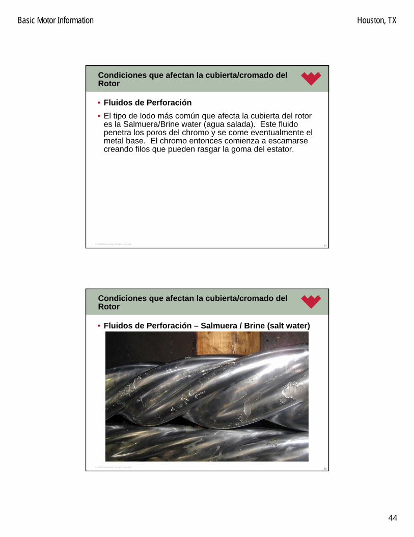
Basic Motor Information Houston, TX
44
87© 2005 Weatherford. All rights reserved.
Condiciones que afectan la cubierta/cromado del Rotor
• Fluidos de Perforación• El tipo de lodo más común que afecta la cubierta del rotor
es la Salmuera/Brine water (agua salada). Este fluidopenetra los poros del chromo y se come eventualmente el metal base. El chromo entonces comienza a escamarsecreando filos que pueden rasgar la goma del estator.
88© 2005 Weatherford. All rights reserved.
Condiciones que afectan la cubierta/cromado del Rotor
• Fluidos de Perforación – Salmuera / Brine (salt water)

Basic Motor Information Houston, TX
45
89© 2005 Weatherford. All rights reserved.
Condiciones que afectan la cubierta/cromado del Rotor
• Fluidos de Perforación• Moore’s Industrial tiene una subcubierta protectora que
puede prevenir este efecto. El lodo puede aun penetrar a la superficie de chromo pero será incapáz de afectar le metal base.
(Process Specification L3-COM-CA-PSP-00012).
Este es más costoso que el cromado estandar, peropuede grandemente reducir los costos de R&M.
90© 2005 Weatherford. All rights reserved.
Condiciones que afectan la cubierta/cromado del Rotor
• Fluidos de Perforación• En algunos casos la subcubierta de MooreCor es
insuficiente para proteger al metal base del rotor de la corrosion. Otro metodo es rociar la base del metal del rotor con carburo de tungnsteno. Esto provee algunaprotección en ambiente dificiles.
• NOTA: Este proceso es muy, muy costoso y toma un largo tiempo para hacerlo, por eso es usadoselectivamente solamente cuando otras opciones yafueron probadas sin exito.

Basic Motor Information Houston, TX
46
91© 2005 Weatherford. All rights reserved.
Por que la Mediciones son Importantes?
• Sin las mediciones del estator no hay modo de decir sieste se ha hinchado. Visualmente, la goma se puede verbien. Nuestras facilidades de Servicio usan como guiauna diferencia de +/- 0.010” de cuando es nuevo paradecir si el relineado es requerido. Es posible de quebolsillos de aire queden atrapados en la goma y son indetectables. Usando un dinamometro como guia y criterio de falla o paso no calienta al estator lo suficientepara crear el efecto de expansion y la posibilidad de queuna falla sea detectada. Solo al medir el estator se puedeel hinchado detectar permitiendo tomar accionesproactivas para la reparación.
92© 2005 Weatherford. All rights reserved.
Por que la Mediciones son Importantes?
• Los rotores y estatores se desgastan con el uso en el tiempo. El desgaste puede no ser visible a simple vista, pero ligeros cambios en los diametrois ocurren cuandofluidos con contenidos solidos son circulados a travéz de este. Al medir los rotores y estatores durante cadaservicio, este desgaste y ragado se puede contabilizar.
• NOTA: Esta guia debe ser usada cuando se opera en lodos base agua y que la temperatura no exceda los 90°C.

Basic Motor Information Houston, TX
47
93© 2005 Weatherford. All rights reserved.
Limitaciones
• Muestras / Chorros tapados
94© 2005 Weatherford. All rights reserved.
Procedimiento de Mejores Prácticas
• De modo de mejorar el control del uso de los estatores, cualquier estator usado en un fluido de perforaciónagresivo debe ser segregado inmediatamente y etiquetadocon el fluido especifico en el que fue usado. Esta reglaaqui debe ser aplicada siempre.
• Cuando seleccione un estator y un rotor para usar en unaaplicacion especifica con un fluido, el técnico de motoresdebe obtener la siguiente información del CoordinadorDireccional. Este le asistirá en hacer la optima selecciónpara el tipo de elastómero del estator y su apropiado rotor en combinación a usar.
- Tipo de Lodo
- Temperatura de Circulación

Basic Motor Information Houston, TX
48
95© 2005 Weatherford. All rights reserved.
Procedimiento de Mejores Prácticas
• Cuando corra en lodos agresivos, seleccione el elastómero que es más resistente a este. Hemos tenidomuchas pruebas de tipos de fluidos para los cuales quetipo de elastómero mejor sirve en ciertas condiciones de perforación. También, se debe prestar atención a la tasade hinchado de la goma debido al lodo. Según necesite, oversize ( aumente la dimension) o double oversize el estators disponible.
96© 2005 Weatherford. All rights reserved.
Procedimiento de Mejores Prácticas
• En pozo calientes, (cualquier cosa que aproxime los 100°C o más alto) el uso de estatores oversized debe ser observado asi como el uso de un elastómero másresistente al hinchado por temperatura

Basic Motor Information Houston, TX
49
97© 2005 Weatherford. All rights reserved.
Procedimiento de Mejores Prácticas
• En caso de que un nuevo fluido se va a usar, y no existeinformación disponible asi como su efecto sobre el elastomero del estator, una muestra de fluido dbe ser enviada para un test de compatibilidad. Esto incluye la determinacion de los efectos sobre los diferenteselastomeros disponible asi como los efectos sobre los agentes aglutinadores. Esto le permite a los tecnicos de motores de seleccionar el mejor elastomero y el ajuste de luz de intereferencia para la aplicacion. Un procedimientoexplicando como la muestra debe ser colectada y sometida para la prueba esta disponible.
98© 2005 Weatherford. All rights reserved.
Procedimiento de Mejores Prácticas
• Cuando inspeccione un estator despues del uso, un boroscopio (analizador de superficie) debe ser usado paraexaminar minuciosamente la superficie completa del elastomero. Los danos pueden no ser vistos en los extremos, un despedece o desprendimiento tempranopuede ser ocultado si este examen no es completado.

Basic Motor Information Houston, TX
50
99© 2005 Weatherford. All rights reserved.
Requerimiento de Muestras de Fluidos de Perforacion –Test de Compatibilidad
• Este procedimiento describes los pasos requeridos paratomar una muestra de fluido de perforacion con el proposito de realizar una prueba de compatibilidad con la seccion de poder del motor de fondo. Esta esbasicamente escrita desde la perspectiva de que el fluidoesta siendo tomado de un sistema de circulacionexistente, y es requerrido debido a problemas de desempeno, es decir el motor esta teniendo unaincompatibilidad con el fluido de perforacion actual. Si la muestra es tomada de un sistema estatico (en almacenamiento), el fluido debe ser bien mesclado antes de tomar la muestra.
100© 2005 Weatherford. All rights reserved.
Requerimiento de Muestras de Fluidos de Perforacion –Test de Compatibilidad
1. Tipo de Contenedor• El contenedor recomendado para ser usado para la
recoleccion de las muestras de fluido debe ser BotellasPlasticas Fluorinatada (FLPE) (ver Figura 026-1). Un tipoespecifico de botella es recomendado ya que es posibleque el fluido capturado en el pozo o sistema cambiedurante el transporte si el envase no es un plastico inerte. Topicamente, los elementos de un fluido de perforacionque podrian danar mas al elastomero son tambien los quemas posiblemente permeen a travez del plastico del envase de la muestra (como son las botellas de plastic soda). Cuando estas son usadas, no se puede decir con certeza que la compatibilidad del fluido resultante obtenidaes representative del fluido real usado en el pozo. Se recomienda botellas de muestra de un-litro de volumen

Basic Motor Information Houston, TX
51
101© 2005 Weatherford. All rights reserved.
Requerimiento de Muestras de Fluidos de Perforacion –Test de Compatibilidad
1. Tipo de Container, continuacion…• Los envases de Vidrio no son aceptables ya que estos son
susceptibles danos durante el manejo y el envio.• Figura 1: Tipo de Envase Aceptable ejamplo *
* Tomado del Catalogo de Cole-Parmer de 2006
102© 2005 Weatherford. All rights reserved.
Requerimiento de Muestras de Fluidos de Perforacion –Test de Compatibilidad
2. Volumen de Fluido• Dos litros del fluido de perforacion debe ser recogido de
modo de poder realizar una lista de pruebas de compatibilidad completa.
3.Cuando Tomar la Muestra de Fluido• Tome la primera muestra en cuanto el problema sea
evidente o surga. De ser posible, calcule el tiempo quetoma una circulacion completa de lodo y tome otramuestra en el punto intermedio (Lag Time)

Basic Motor Information Houston, TX
52
103© 2005 Weatherford. All rights reserved.
Requerimiento de Muestras de Fluidos de Perforacion –Test de Compatibilidad
4.Donde Tomar la Muestra• Una muestra de fluido debe ser tomada de la linea de
succion. Esto va a proveer la muestra mas precisa de fluido para analisis. Esta va a reflejar que es lo que estasiendo bombeado al pozo.
5.Como llenar la botella• Llenela hasta el tope. Asegure que no haya aire presente
en la botella cuando le coloque la tapa. Esto va a ayudara prevenir la perdida de los “volatiles” en el fluido quepueden tender a escapar al volumen de aire de la botelladurante el transporte & y son por ende perdidos cuando se habra esta.
104© 2005 Weatherford. All rights reserved.
Requerimiento de Muestras de Fluidos de Perforacion –Test de Compatibilidad
6. Documentacion Requerida• La siguiente documentacion es requerida para ser
sometida junto con la muestra con el proposito de un envioy manejo seguro asi como para el analisis.
» (a) MSDS – Una copia del Material Safety Data Sheet debe estar disponible en la oficina del Mud Man
» (b) Descripcion del Fluido – Cualquier info adicional acerca del drilling fluid incluyendo el tipobase, los aditivos agresivos o no, relacionaceite/agua, etc..
» (c) La Hoja de Datos del Lodo/Mud Data Sheet – sies posible, obtenga una copia del mud data sheet con el Mud Man el mismo dia de toma de la muestra comoreferencia.
Basic Motor Information Houston, TX
53
105© 2005 Weatherford. All rights reserved.
Requerimiento de Muestras de Fluidos de Perforacion –Test de Compatibilidad
6. Documentacion Requerida, continua…» (d) Detalles de la fecha, hora, y la localidad donde
la muestra fue tomada. La informacion del Cliente, Pozo, localidad, numero de trabajo, y el PerforadorDirectional supervisando la muestra debe incluirse
» (e) Las condiciones del hoyo en el momento –Temperaturaa y Presion de Fondo. Estos son requeridos para establecer que condiciones existiancuando el problema de compatibilidad surgio y poderreproducirlas en la prueba.
106© 2005 Weatherford. All rights reserved.
Requerimiento de Muestras de Fluidos de Perforacion –Test de Compatibilidad
7.Envio de la Muestra de Fluido• Enviar la muestra con la documentacion requerida al
Directional Drilling Coordinator regional en su area, y el vaa hacer los arreglos para envio a una facilidad de pruebas.
• Este procedimiento puede ser encontrado en el WI-GEN-027 "Procedures for Processing Power Section Compatibility Tests".
Basic Motor Information Houston, TX
54
107© 2005 Weatherford. All rights reserved.
Limitaciones de contenido de Solidos y LCM con los motores de fondo
• Grandes cantidades del solidos abrasivos en el fluido van a desgastar drasticamente los componentes de un drilling motor. Se recomienda que el contenido de solidos en elodo se mantenga por debajo de 5% para una vidaoperacional aceptable. Los solidos deben idealmente ser de forma redondeada y no filosos, lo cual puede causar un desgaste pre-maturo a la goma del estator.
108© 2005 Weatherford. All rights reserved.
Limitaciones de contenido de Solidos y LCM con los motores de fondo
• El tamono de los solidos tambien necesita ser monitoreado, y basado en el tamano nominal de un drilling motor, debera mantenerse por debajo de 0.15” en tamanopara un motor de 4 ¾” y mas grandes (para motores maspequenos contacte al equipo de Drilling Tools Engineering) y asegurese de que estas son lo suficientepequenas para pasar a traves de las cavidades formadasentre el rotor y el estator. Finalmente, mientras mas duroes el solido, mas abrasivo este sera contra los componentes del motor de fondo. En un motor Lubricadopo lodo, la luz entre las camisas es de solo 0.010 –0.020”.

Basic Motor Information Houston, TX
55
109© 2005 Weatherford. All rights reserved.
Limitaciones de contenido de Solidos y LCM con los motores de fondo
• Los solidos finos, y duros abrasivos como lo es la arena debe ser mantenidos por debajo de 0.5% ya que ellosdanan el elastomero extremadamente. En caso de que los solidos esten cerca de estas limitaciones, se espera quelos componentes del motor se desgasten aceleradamete y debe ser tomado en cuenta cuando se evalue el motor para re-uso antes del servicio.
110© 2005 Weatherford. All rights reserved.
Limitaciones de contenido de Solidos y LCM con los motores de fondo
• El Material Antiperdidad (Lost circulation materials) puedeser usado con seguridad con los motores de Weatherford siempre y cuando este material cumpla con los requerimientos de solidos vistos anteriormente. Se recomienda que el LCM se limite a concentraciones de 40 lb/bbl para asegurar que no ocurran blockeos dentro del motor cuando se circulan. Altas concentraciones son posibles, pero existe el riesgo relacionado con el empacado del material en la seccion de poder del motor, suspendiendo su operacion posterior. Ademas, el material LCM debe ser anadido poco a poco para asegurar queniveles aceptables de concentraciones de LCM seanbombeadas al fondo.

Basic Motor Information Houston, TX
56
111© 2005 Weatherford. All rights reserved.
Ensamble de Transmision / Drive Assembly
• Debido a la naturaleza del diseno de la seccion de poder, la rotation del rotor es eccentrica dentro del estator. Para compensar este movimiento eccentrico y convertirlo en pura rotacion concentrica, El motor PrecisionDrill™ utilizaun ensamble de transmision articulada de alta resistencia. Este ensamble impulsor consiste en un eje impulsor con una junta lubricada y sellada en cada extremo.
112© 2005 Weatherford. All rights reserved.
Ensamble de Transmision / Drive Assembly
• La junta articulada esta disenada para soportar altos valores de torque generados por la seccion de podermientras crea una tension minima a travez de los componentes del ensamble de transmision para aumentarla confiabilidad y extender la vida util. El ensamble de transmision tambien provee un punto en la lineapropulsora que compensa el doblamiento o angulo de ajuste en el bend del motor para el control direccional.

Basic Motor Information Houston, TX
57
113© 2005 Weatherford. All rights reserved.
Ensamble de Transmision / Drive Assembly
114© 2005 Weatherford. All rights reserved.
Ensamble Ajustable / Adjustable Assembly
• Todos los motores PrecisionDrill™ son suministrados con un ensamble de ajuste en campo. El ensamble ajustablepuede ser arreglado de zero a dos, tres o cuatro grados en incrementos variables en el campo. Este diseno durable resulta en un amplio rango de tasas de construccionpotenciales para uso en pozos direccionales, horizontalesy pozos de reentradas. Tambien, para minimizar el desgaste en los componentes del ensamble ajustable, se han integrado los anillos de desgaste en la parte superior e inferior del ensamble bend.

Basic Motor Information Houston, TX
58
115© 2005 Weatherford. All rights reserved.
Ensamble Ajustable / Adjustable Assembly
116© 2005 Weatherford. All rights reserved.
Operacion de Ajuste - 3° LBTB ML Pagina 1 de 4
3.00°M2.97°L2.90°K2.77°J2.60°I2.38°H2.12°G1.83°F1.50°E1.15°D0.78°C0.39°B
0°A
Bend Angle
Stamped Letters
82,00060,0009-5/8”54,60040,0008”43,40032,0006-3/4”
Adjustable (N-m)
Adjustable (Ft-lbs)
Tool Size
Adjustable Bent Housings Torque Specifications & Adjustable Bent Housings

Basic Motor Information Houston, TX
59
117© 2005 Weatherford. All rights reserved.
Operacion de Ajuste - 3° LBTB ML Pagina 2 de 4
• Desenrosque debajo del anillo ajustable al colocar las llaves del piso en el adjustable bent sub y en el housing adaptor del estator.
* AHORA USE LAS LLAVES DE CADENA SOLAMENTE.• Sostenga la herramienta con la llave de cadena tool en el housing adaptor del
estator y levante el bent sub adjustable con la llave de cadenas hasta que la carade la caja del housing adaptor del estator este 1/2” por encima de la cara del anillo adjustable. (Pasos 1 y 2)
* Asegure que el pins en el anillo ajustable este enganchado hasta que la carade la caja despeje el hombro.
• Deslice el anillo ajustable hacia arriba hasta la base en el hombro del estator del adaptador housing. Empuje si es necesario.
• Sostener la herramienta en el bent sub ajustable con las llaves de cadena y ajusteusando las llaves de cadena en el anillo ajustable. Aumente el ángulo girando a la derecha mirando hacia abajo desde el tope de la herramienta. Disminuir el ángulogirando a la izquierda. El ángulo deseado es alcanzado alineando la misma letrade ambos lados. (Es decir. Si un ajuste de 1.15 grados es deseado la letra “D” en bend sub y “D” en el anillo ajustable deben ser alineados exactamente antes de que el anillo ajustable sea enroscado nuevamente.)
118© 2005 Weatherford. All rights reserved.
Operacion de Ajuste - 3° LBTB ML Pagina 3 de 4
• Deslice el anillo de ajuste hacia abajo hasta que los pin estanenganchados completamente con el bent sub ajustable. * Asegure quelas caras del adjustable ring y el adjustable bent sub estan en contactoantes de continuar.
• Enrosque hasta que las caras sellen con el estator housing adaptor • Sostenga la herramienta con las llaves de cadena en el stator housing
adaptor & gire el ring adjustable hasta el stator housing adaptor.• Coloca la herramienta en cuñas. Torquee la conneccion con los valores
especificados debajo al colocar las llaves del piso sobre el adjustable bent sub y el estator housing adaptor.
• Si se usa un kick pad (almohadilla) ajustable, el pad debe estar orientadoen la cara baja del bend. Esto puede lograse al abrir en la camisaprotectora de rosca en el bearing housing. El adjustable kick pad puededeslizarse hacia abajo, orientado como se desea y reenganchado. La camisa protectora de la rosca entonces se torquea de nuevo segun se especifica en Appendix 1 del Motor Handbook, o la especificaciones L3-COM-CA-MOT-F0050.

Basic Motor Information Houston, TX
60
119© 2005 Weatherford. All rights reserved.
Operacion de Ajuste - 3° LBTB ML Pagina 4 de 4
�������������
�������������
������
��
����
����
��
��
��
�
�
���� () �*+,�"-����(
"-.�*��/�� +,�
"-.�*��/��&�,����/
� 0,1 ��
�������������
�������������
� � ,�,�*
��
����
����
��
��
��
�
�
�������������
�������������
2�3��4�
������5�
"**�/�6
��
����
����
��
��
��
�
�
�4�����7��+,�*����0+�1�7
�����35�8
�������������
�������� ��
��
����
����
��
��
��
�
�
�������������
���������� ��
������
��
����
����
��
��
��
�
�
�������������
��
����
����
��
��
��
�
�
�������� ��
������5��
• Vea tambien la ultima revision de QF-MOT-F0031
120© 2005 Weatherford. All rights reserved.
Operacion de Ajuste - 2°, 3° & 4° Pagina 1 de 4
QPONMLKJIHGFEDCBA
Stamped Letters
3.00°2.97°2.90°2.77°2.60°2.38°2.12°1.83°1.50°1.15°0.78°0.39°
0°
3° Actual Kick Sub
Angle
4.00°3.98°3.92°3.83°3.70°3.53°3.33°3.09°2.83°2.00°2.54°1.96°2.22°1.85°1.89°1.66°1.53°1.41°1.16°1.11°0.78°0.77°0.39°0.39°
0°0°
4° Actual Kick Sub
Angle
2° Actual Kick Sub
Angle
47,50035,0007”40,70030,0006-1/4”20,30015,0005”17,70013,0004-3/4”
Adjustable (N-m)
Adjustable (Ft-lbs)
Tool Size
Adjustable Bent HousingsTorque Specifications
& Adjustable Bent Housings
En el area sombreada, note las diferencias en el angulo de bend para “G”.
Basic Motor Information Houston, TX
61
121© 2005 Weatherford. All rights reserved.
Operacion de Ajuste - 2°, 3° & 4° Pagina 2 de 4
• Desenrosque el adjustable bent sub debajo del anillo ajustable colocandolas mordazas del taladro en el stator housing adaptor y en el bearing housing. * AHORA USE LAS LLAVES DE CADENAS SOLAMENTE.
• Sostenga la herramienta con la mordaza sobre el anillo ajustable y desenrosque el bearing housing con la llave de cadenas hasta que la carade la caja este 1/2” debajo de la cara del anillo ajustable. (vea la Figuras 1 y 2)
• * Asegure que los pins en el anillo ajustable esten enganchados hastaque la cara de la caja deje al hombro.
• Deslice el anillo ajustable hacia abajo hasta que fondee en el hombro del bearing housing. Empuje si es necesario.
• Sostenga la herramienta en el adjustable bent sub/stator housing adaptor con las llaves de cadena y ajuste usando la llave de cadena sobre el anillo ajustable al rotar en sentido horario mirando hacia abajo en el hoyo. Disminuya angulo al rotar en contra sentido horario. El angulo deseado se obtiene al alinear la misma letra de las dos caras (como por ejemplo sidesea un ajuste de 1.11 grados la letra “D” en el bent sub y en la letra“D” en el anillo ajustable debe exactamente alinearse antes de que el anillo de ajuste sea reenganchado) El tipo de ajuste (2o o de 3o) se puede determinar al chequear cuantas letras estan estampadas en esteen comparacion con la tabla debajo.
122© 2005 Weatherford. All rights reserved.
Operacion de Ajuste - 2°, 3° & 4° Pagina 3 de 4
• Deslice el anillo ajustable hasta que los pins esten totalmente engranadoscon el adjustable bent sub/stator housing adaptor.
• * Asegurese de que las caras del anillo ajustable y la del adjustable bent sub/stator housing adaptor esten en contacto antes de proseguir.
• Dope la cara del bearing housing.• Sostenga la herramienta con las llaves de cadenas en el anillo ajustable
& gire al bearing housing al anillo ajustable.• Coloque la herramienta en cunas. Torquee la coneccion con los valores
especificados debajo al colocar las mordazas del taladro en el adjustable bent sub/stator housing adaptor y en el bearing housing.
• Si se esta usando un adjustable kick pad (almohadilla de pateo), la almohadilla debe estar orientada en la cara baja del bend. Esto puedelograrse al desenroscar la camisa protectora de rosca del bearing housing. El adjustable kick pad puede entonces deslizarce fuera, orientarsegun desee y enrosacar de regreso. La camisa protectora de rosca esentonces toqueada con los valores segun se especifica en el Appendix 1 del Motor Handbook, o en la especificacion L3-COM-CA-MOT-F0050.

Basic Motor Information Houston, TX
62
123© 2005 Weatherford. All rights reserved.
Operacion de Ajuste - 2°, 3° & 4° Pagina 4 de 4
���������������
���������������
������������
��������
������������
� ������������
� ����������������������������� ����
� �����������
������
����������
���� ��
��������������
���������������
����������
���� ��
����������
���������������
��������
����������
� ������������
���������������
������
�����������
• Vea la ultima revision de QF-MOT-F0056
124© 2005 Weatherford. All rights reserved.
2° High-Increment Operacion de Ajuste – OL & ML Pagina 1 de 4
2.00°1.99°1.97°1.93°1.88°1.81°1.73°1.64°1.53°1.41°1.29°1.15°1.00°0.85°0.68°0.52°0.35°0.17°
Actual Kick Sub Angle
17,60013,0005”
Adjustable (N-m)
Adjustable (Ft-lbs)
Tool Size
Adjustable Bent Housings Torque Specifications & Adjustable Bent Housings

Basic Motor Information Houston, TX
63
125© 2005 Weatherford. All rights reserved.
2° High-Increment Operacion de Ajuste – OL & ML Pagina 2 de 4
• Abrir/desarmar el motor debajo del anillo ajustable al colocar las llaves del taladro en el adjustable bent sub y el stator housing adaptor.
* AHORA USE SOLO LLAVES DE CADENA.• Sostenga las herramienta con las llaves de cadena en el stator housing
adaptory y desarme el adjustable bent sub con la llave de cadena hastaque la cara de la caja del stator housing adaptor este 1/2” encima/ separada del anillo ajustable. (vea Figures 1 y 2)
* Asegure que los pins en el anillo ajustable esten engranados hastaque la cara de la caja deje el hombro.
• Deslice al anillo ajustable hasta que este fondee en el hombro del stator housing adaptor. Use el empuje si es necesario.
• Sotenga la herramienta en el adjustable bent sub con las llaves de cadena sobre el anillo ajustable. Aumente angulo al rotar en sentidohorarario miranddo hacia abajo en el pozo. Dimsinuya angulo al rotar en contrasentido horario. El angulo deseado se logra al alienar la misma letrade ambos lados( como ejemplo si desea un ajuste de1.15 grados la letra“D” en el bent sub y la letra “D” en anillo ajustable deben estarexactamente alineadas antes del que el adjustable ring es re-enganchado.)
126© 2005 Weatherford. All rights reserved.
2° High-Increment Operacion de Ajuste – OL & ML Pagina 3 de 4
• Deslice al adjustable ring hacia abajo hasta que los pins esten engrandoscompletamente con el adjustable bent sub. * Asegurese que la cara del anillo ajustable y la del adjustable bent sub este en contacto antes de proceder.
• Permita el sello del stator housing adaptor.• Sostenga la herramienta con las llaves de cadena en el stator housing
adaptor & y gire el anillo ajustable sobre el stator housing adaptor.• Coloque la herramienta en cunas. Torquee la conneccion con los valores
especificados debajo al colocar las llaves del taladro en el adjustable bent sub y stator housing adaptor.
• Si se usa un adjustable kick pad, el pad debe orientarse para la cara bajadel bend. Esto puede ser logrado al desenroscar la camisa protectorasobre el bearing housing. El adjustable kick pad pueden entoncesdeslizarce hacia abajo, orientar segun se desee y renganchar. La camisaprotectora de rosca es torqueada nuevamente con los valoresespecificados en el Appendix 1 del Motor Handbook, o en la especificaciones L3-COM-CA-MOT-F0050.

Basic Motor Information Houston, TX
64
127© 2005 Weatherford. All rights reserved.
2° High-Increment Operacion de Ajuste – OL & ML Pagina 4 de 4
• Vea la ultima revision de QF-MOT-F0073
�����������������
������� �� �����
��������
���������������
������� !��������"#$�% �������!
���"���
������
#$
���&����
�������'�(��
��')��(�
����(&*����(�(��
+,-++.��/,0
������(�&���(�(��
���&�����
�������'�(��
�������'�(��
��')��(�
������(�(��
���(�&����� �1#$#$ #$ ���(�&
����� �1 ���(�&����� �1
128© 2005 Weatherford. All rights reserved.
Operacion de Ajuste - 3° LBTB High-Torque ML Pagina 1 de 4
3.00°M2.97°L2.90°K2.77°J2.60°I2.38°H2.12°G1.83°F1.50°E1.15°D0.78°C0.39°B
0°A
Bend Angle
Stamped Letters
16,30012,0005”16,30012,0004-3/4”
Adjustable (N-m)
Adjustable (Ft-lbs)
Tool Size
Adjustable Bent Housings Torque Specifications & Adjustable Bent Housings

Basic Motor Information Houston, TX
65
129© 2005 Weatherford. All rights reserved.
Operacion de Ajuste - 3° LBTB High-Torque ML Pagina 2 de 4
• Abrir/desarmar el motor debajo del anillo ajustable al colocar las llaves del taladro en el adjustable bent sub y el stator housing adaptor.
* AHORA USE SOLO LLAVES DE CADENA.• Sostenga las herramienta con las llaves de cadena en el stator housing
adaptory y desarme el adjustable bent sub con la llave de cadena hastaque la cara de la caja del stator housing adaptor este 1/2” encima/ separada del anillo ajustable. (vea Figures 1 y 2)
* Sostenga la herramienta con las llaves de cadena en el stator housing adaptor & y gire el anillo ajustable sobre el stator housing adaptor.
• Deslice al anillo ajustable hasta que este fondee en el hombro del stator housing adaptor. Use el empuje si es necesario..
• Sotenga la herramienta en el adjustable bent sub con las llaves de cadena sobre el anillo ajustable. Aumente angulo al rotar en sentidohorarario miranddo hacia abajo en el pozo. Dimsinuya angulo al rotar en contrasentido horario. El angulo deseado se logra al alienar la misma letrade ambos lados( como ejemplo si desea un ajuste de1.15 grados la letra“D” en el bent sub y la letra “D” en anillo ajustable deben estarexactamente alineadas antes del que el adjustable ring es re-enganchado.)
130© 2005 Weatherford. All rights reserved.
Operacion de Ajuste - 3° LBTB High-Torque ML Pagina 3 de 4
• Deslice al adjustable ring hacia abajo hasta que los pins esten engrandoscompletamente con el adjustable bent sub. * Asegurese que la cara del anillo ajustable y la del adjustable bent sub este en contacto antes de proceder.
• Permita el sello del stator housing adaptor.• Sostenga la herramienta con las llaves de cadena en el stator housing
adaptor & y gire el anillo ajustable sobre el stator housing adaptor.• Coloque la herramienta en cunas. Torquee la conneccion con los valores
especificados debajo al colocar las llaves del taladro en el adjustable bent sub y stator housing adaptor.
• Si se usa un adjustable kick pad, el pad debe orientarse para la cara bajadel bend. Esto puede ser logrado al desenroscar la camisa protectorasobre el bearing housing. El adjustable kick pad pueden entoncesdeslizarce hacia abajo, orientar segun se desee y renganchar. La camisaprotectora de rosca es torqueada nuevamente con los valoresespecificados en el Appendix 1 del Motor Handbook, o en la especificaciones L3-COM-CA-MOT-F0050.

Basic Motor Information Houston, TX
66
131© 2005 Weatherford. All rights reserved.
Operacion de Ajuste - 3° LBTB High-Torque ML Pagina 4 de 4
������� �� �����
��������
���������������
������� !����
������
���&����
��������
��������
��������
�����
�
���
���
�
��������
��������
��������
�����
�
���
���
���
�����
��
�����
�������'�(��
��')��(�
����(&*����(�(��
+,-++.��/,0
������(�&���(�(��
���&�����
�������'�(��
�������'�(��
��')��(�
������(�(��
��� ���(�&����� �1 �
�� ���(�&����� �1
��� ���(�&����� �1
• See also the latest revision of QF-MOT-F0125
132© 2005 Weatherford. All rights reserved.
Seccion de Rodamiento Lubricada por Lodo/ Mud Lubricated Bearing
• La seccion de rodamientos contiene los rodamientosradiales y de soporte o apoyo (thrust bearings) quetransmiten las caragas axiales y radiales de la mecha a la sarta de perforacion, mientras se provee la lineapropulsora que permite a la seccion de poder girar la mecha. Los rodamientos lubricados por lodo permiten unalimitada porcion del fluido de perforacion que esbombeados a traves del motor ser bypaseado a travez de los rodamientos (approx. 7%), proviendo lubricacion y enfriamiento. El fluido bypaseado a traves de los rodamientos sale directamente encima de la caja de la mecha y se reune con el flujo primario para ayudar a limpiar el hoyo.

Basic Motor Information Houston, TX
67
133© 2005 Weatherford. All rights reserved.
Estabilizacion
• Los housing de los rodamientos estan disponibles con estabilizadores del tipo que se enrosca sobre la camisa. Este tipo de enrosque sobre la camisa provee la opcion de instalar una camisa estabilizadora sobre el motor en el piso de perforacion en cuestion de minutos. El motor quetiene roscas en su extremo inferior esta cubierto con unacamisa lisa protectora cuando no se requiere unaestabilizacion. Los housing de rodamientos del tipo quetienen roscas en el son los estandares que son suministrados.
134© 2005 Weatherford. All rights reserved.
Tugger / Winch Line
• En USA se usan muchos diferentes componentespara los equipos del taladro.
• Como son. Dog collar / safety clamp / wedding band.

Basic Motor Information Houston, TX
68
135© 2005 Weatherford. All rights reserved.
Kick Pads / almohadillas pateadoras
• Los kick pads eccentricos pueden tambien ser usados en los motores PrecisionDrill™ desde 4 3/4” (121 mm) hasta9 5/8” (244 mm). Estos kick pad se ajustan para alinearsecon la cara baja del bend angle del motor para aumentarla capacidad de construccion de angulo. Esto le permitiratambien tener ajustes menores para tasas de construcionsimilares y disminuir la tension radial aplicada al ensamblede rodamientos, y permite una rotacion segura del motor. Ellos pueden ser instalados en el campo la enroscarlossobre los bearing housing especiales con esta capacidad.
136© 2005 Weatherford. All rights reserved.
Kelly / Top Drive
• Kelly o Top Drive?

Basic Motor Information Houston, TX
69
137© 2005 Weatherford. All rights reserved.
Arrivo a la localidad
• Cuando arribe al sitio, introduzcase con el Company Man.• Segundo, Mida las herramientas / strap your tools. Si por
alguna rason se ha cometido un error (como un sub con la conneccion incorrecta ha sido enviado) podrias tenertiempo para corregir la situacion antes de comenzar a levantar herramientas al BHA.
• (Se Incluye un documento para tool Strapping aqui)
138© 2005 Weatherford. All rights reserved.
OPERACION DEL DRILLING MOTOR
• En orden para un mejor desempeno y una vida optima del motor PrecisionDrill™ lubricado por lodo, los siguientesprocedimientos estandares deber ser seguidos durante la operacion. Pequenas variaciones pueden ser requeridascon cambios en las condiciones de perforacion y equiposde perforacion, pero debe tratarse de cumplir con estosprocedimientos los mas cerca posible.

Basic Motor Information Houston, TX
70
139© 2005 Weatherford. All rights reserved.
OPERACION DEL DRILLING MOTOR
• PROCEDIMIENTO DE ENSAMBLAJE Y CHEQUEO DE EQUIPO EN SUPERFICIE ANTES DE CORRER AL HOYO
• Debemos chequear manualmente siempre el Dump Subs usando un mango de martillo de trineo para manualmenteempujar el Dump Sub valve cerrar / hacia abajo.
140© 2005 Weatherford. All rights reserved.
OPERACION DEL DRILLING MOTOR
• PROCEDIMIENTO DE ENSAMBLAJE Y CHEQUEO DE EQUIPO EN SUPERFICIE ANTES DE CORRER AL HOYO
• Danos en los PDC inserts y danos en cortadores / escarean el casing.

Basic Motor Information Houston, TX
71
141© 2005 Weatherford. All rights reserved.
OPERACION DEL DRILLING MOTOR
• PROCEDIMIENTO DE ENSAMBLAJE Y CHEQUEO DE EQUIPO EN SUPERFICIE ANTES DE CORRER AL HOYO
• A pesar que los PrecisionDrill™ mud lubricated motor son despachados del taller completamente inspecionados y probados, algun chequeo inicial debe ser completadoantes de correrlo al hoyo. Este proceso de chequeo en superficie debe ser solamente usado con sistemas de lododel equipo de peforacion
• CAUTION: Para evitar danos potenciales sobre la mecha, motor, y BOP, este chequeo preliminar debe ser completado sin la mecha conectada. Un protector de roscas debe ser instalado en la caja de la mecha cuandose esta moviendo el motor, pero debe ser quitado antes de la prueba con flujo.
142© 2005 Weatherford. All rights reserved.
OPERACION DEL DRILLING MOTOR
• PROCEDIMIENTO DE ENSAMBLAJE Y CHEQUEO DE EQUIPO EN SUPERFICIE ANTES DE CORRER AL HOYO, continua
• (1) Un correcto lift sub debe ser siempre instalado y usadopara mover la herramienta hacia y desde el piso de perforacion, y el levantador debe estar roscado. Tambienasegurese que la conneccion entre el lift sub y el drilling motor este ajustada. Para levantar el drilling motor al pisode perforacion, use el tugger line asegurado alredeor del lift sub. Levante el motor PrecisionDrill™ con el elevador y coloquelo en las cunas de la mesa rotaria. Instale el collarin/dog collar / las llaves de seguridad.

Basic Motor Information Houston, TX
72
143© 2005 Weatherford. All rights reserved.
OPERACION DEL DRILLING MOTOR
• PROCEDIMIENTO DE ENSAMBLAJE Y CHEQUEO DE EQUIPO EN SUPERFICIE ANTES DE CORRER AL HOYO, continua
• NOTA: El lift sub suministrado con el drilling motor debeser usado solo para levantar el drilling motor. La capacidad del lift sub esta restringida para el peso del drilling motor y no debe ser usada para otros propositos.
• NOTA: Solo aplique las llaves del equipo en las areas identificadas del motor. Todas la connecciones del drilling motor estan torquedas en el taller de servicios de Weatherford. Torque adicionales en el rig floor no esnecesario, y se intenta esto puede causar danos.
144© 2005 Weatherford. All rights reserved.
OPERACION DEL DRILLING MOTOR
PROCEDIMIENTO DE ENSAMBLAJE Y CHEQUEO DE EQUIPO EN SUPERFICIE ANTES DE CORRER AL HOYO, continua
• (2) Remueva el levantador/lift sub y conecte el kelly al drilling motor, retire el collarin/perro o mordaza de seguridad (dog collar / safety clamp), y levante al motor de fondo fuera de cunas. Retire el protector de roscas de la caja inferior (bit box) e inspeccione las roscas por danos.
• (3) Baje el motor de fondo hasta el extremo superior de la mesa rotaria. Si el motor de fondo tiene un dump sub, coloquelo de manera que las boquillas del dump sub estenvisibles debajo de la mesa rotaria.

Basic Motor Information Houston, TX
73
145© 2005 Weatherford. All rights reserved.
OPERACION DEL DRILLING MOTOR
• PROCEDIMIENTO DE ENSAMBLAJE Y CHEQUEO DE EQUIPO EN SUPERFICIE ANTES DE CORRER AL HOYO, continua
• PRECAUCION: La valvula del dump sub se mantendraabierta hasta que exista suficiente presion de fluido paracerrarla. Por cosiguiente, el motor de fondo debe ser colocado por debajo de la mesa. Esto prevenira que el flujo inicial de lodo no se derrame a presion sobre la mesa.
146© 2005 Weatherford. All rights reserved.
OPERACION DEL DRILLING MOTOR
• PROCEDIMIENTO DE ENSAMBLAJE Y CHEQUEO DE EQUIPO EN SUPERFICIE ANTES DE CORRER AL HOYO, continua
• (4) Lentamente encienda las bombas. Asegure que el fluido de perforacion este fluyendo de las boquillas del dump sub, si es el caso de su uso. Aumente la tasa de flujo hasta que las boquillas del dump sub se cierren, y el fluido de perforacion deje de salir a traves de estos. Anotela tasa de circulacion y la presion del standpipe.
• PRECAUCION: No exceda la tasa de flujo maxima recomendada para la prueba.

Basic Motor Information Houston, TX
74
147© 2005 Weatherford. All rights reserved.
OPERACION DEL DRILLING MOTOR
• PROCEDIMIENTO DE ENSAMBLAJE Y CHEQUEO DE EQUIPO EN SUPERFICIE ANTES DE CORRER AL HOYO, continua
• (5) Levante el motor de fondo hasta que el bit box estevisible. Este debe estar rotaando a una baja, y constantevelocidad. Preste oidos a la bearing section del motor de fondo en caso de un ruido excesivo de los rodamientos, especialmente si este motor ha sido usado previamente, sin servicio aun. Ademas, asegurese que una porcion del fluido de perforacion este saliendo directamente del motor encima del bit box. De 5 a 10 porciento del total del flujocirculando a travez de este punto es aceptable.
148© 2005 Weatherford. All rights reserved.
OPERACION DEL DRILLING MOTOR
• PROCEDIMIENTO DE ENSAMBLAJE Y CHEQUEO DE EQUIPO EN SUPERFICIE ANTES DE CORRER AL HOYO, continua
• (6) Si el motor de fondo tiene un ensamble de dump sub, antes de parar bombas, el motor debe ser colocadodebajo de la mesa rotaria. Asegurese que el fluido estefluyendo fuera de las boquillas del dump sub despues de apagar bombas. Es posible que la valvula del dump sub se quede cerrada despues de esta prueba si se queda la presion entranpada. Si esto ocurre, ningun fluido saldra de las boquillas. Para remover la presion entranpada, descargue alguna presion del standpipe y la valvula se abrira.
• PRECAUTION: El checkeo de superficie debe ser tan corto como posible; esto meramente para asegurar que el motor de fondo rote cuando pase el flujo.

Basic Motor Information Houston, TX
75
149© 2005 Weatherford. All rights reserved.
OPERACION DEL DRILLING MOTOR
• PROCEDIMIENTO DE ENSAMBLAJE Y CHEQUEO DE EQUIPO EN SUPERFICIE ANTES DE CORRER AL HOYO, continua
• (7) Un vez que el flujo fue cortado, la luz o juego del thrust bearing debe ser checkeada. Primero, con el motor de fondo colgando/sin peso sobre la mecha, una medicion se puede hacer entre la cara del bottom-most del motor housings el extremo superior del collar en el bit box. Anotar esta medida como D1. Similarmente, tomar la misma medida con peso sobre la mecha y grabar estamedida como D2. Sustraer D2 de D1 para calcular la cantidad de juego axial en el motor. Esta no debe excederlos valores en la Table 6 del Appendix 4.
150© 2005 Weatherford. All rights reserved.
OPERACION DEL DRILLING MOTOR
• PROCEDIMIENTO DE ENSAMBLAJE Y CHEQUEO DE EQUIPO EN SUPERFICIE ANTES DE CORRER AL HOYO, continua
• (8) El juego radial en el motor de fondo puede ser checkeado al colocar una llave en el bit box y deflectaresta radialmente - hasta 0.040 de movimiento diametrical es aceptable.
• (9) Despues de este chequeo en superficie, la mechadebe ser ensamblada con ayuda del bit-breaker, mientrasse sostiene el bit box estacionario con la llave rotatoria. Asegurece de evitar el contacto de la capa extremadirectamente encima del bit box con la mordaza de la llave.

Basic Motor Information Houston, TX
76
151© 2005 Weatherford. All rights reserved.
OPERACION DEL DRILLING MOTOR
• PROCEDIMIENTO DE ENSAMBLAJE Y CHEQUEO DE EQUIPO EN SUPERFICIE ANTES DE CORRER AL HOYO, continua
• Podria desenroscar los componentes internos e (introducirdanos por los solidos del wellbore en las secciones de bearing/estator)
152© 2005 Weatherford. All rights reserved.
OPERACION DEL DRILLING MOTOR
• PROCEDIMIENTO DE ENSAMBLAJE Y CHEQUEO DE EQUIPO EN SUPERFICIE ANTES DE CORRER AL HOYO, continua
• CUIDADO: Se recomienda que usted nunca sostenga el bit box estationario y rote el motor en contra del sentidohorario, o que sostenga al motor de fondo estacionario y rote al bit box en sentido horario. Esto puede causarposiblemente que las connecciones internas se desenrosquen y se danen. Aunque la rotación en la dirección opuesta dé lugar al fluido de perforacion que se salga por el extremo superior, las conexiones internas no estarán en peligro de la desconexión
• Cuando esten hoyo abajoe, el fluido de perforacion y los recortes pueden ser succionados hacia dentro del motor trabando la seccion de poder.

Basic Motor Information Houston, TX
77
153© 2005 Weatherford. All rights reserved.
OPERACION DEL DRILLING MOTOR
• PROCEDIMIENTO DE ENSAMBLAJE Y CHEQUEO DE EQUIPO EN SUPERFICIE ANTES DE CORRER AL HOYO, continua
• (10) Si el motor de fondo ha sido usado previamente, unainspeccion general debe ser completada. Una inspeccionvisual general del motor completo debe ser llevada a cabopara detectar sellos faltantes, daños al cuerpo, o perdidade la conneccion. Asegure que La revision de requerimientos de descarte o “Laydown Requirements Review” (Appendix 4, or L3-COM-CA-MOT-F0051) ha sidocompletada y todas las limitaciones han sido tomadas en cuenta. Si las limitaciones han sido excedidas como se describe en la forma, el motor de fondo debe ser descartado y sustituido.
154© 2005 Weatherford. All rights reserved.
OPERACION DEL DRILLING MOTOR
• PROCEDIMIENTO DE ENSAMBLAJE Y CHEQUEO DE EQUIPO EN SUPERFICIE ANTES DE CORRER AL HOYO, continua
• (11) Configure el ensamble ajustable para el bend deseado. Las instrucciones para este procedimientopueden ser encontradas en el Appendix del Manual (handbook). Una copia es tambien anexada a cada motor antes de que es enviado desde el taller de servicios. El torque requerido en el ensamble ajustable es tambienindicado en las especificaciones del motor.
• (12) Si un float sub es usado, este debe ser colocadoinmediatamente encima del motor.

Basic Motor Information Houston, TX
78
155© 2005 Weatherford. All rights reserved.
OPERACION DEL DRILLING MOTOR
• VIAJANDO A FONDO• Generalmente, una sarta de perforacion con un motor
PrecisionDrill™ puede ser bajado al hoyo como un ensamblaje de fondo estandar. El motor de fondo esrobusto, pero cuidados deben ser tomados para controlarla velocidad durante los viajes a fondo. La sarta de perforacion debe ser bajada con el bloque abierto y cuidado especial debe ser tomado para pasar a traves de la B.O.P., zapara del revestidor, colgadores de los liner, puentes, y cuando se acerque a fondo. Los puntosestrechos deben ser trspasados con bombas y repasandosuavemente. Cuando repase, la sarta debe ser rotadaperiodicamente para evitar hacer sidetracks.
156© 2005 Weatherford. All rights reserved.
OPERACION DEL DRILLING MOTOR
• VIAJANDO A FONDO, cont’• Cuando haga viajes a profundidades extrema, o cuando la
temperatura del hoyo sea alta, periodicamente se recomienda parar y circular. Esto previene que la mechase tape y ayuda al enfriamiento del motor, preveniendodanos por alta temperatura.
• El fluido no debe ser circulado por el motor cuando se encuetre dentro del casing si esta usando mecha PDC o de Diamantes, ya que dañaria los cortadores.

Basic Motor Information Houston, TX
79
157© 2005 Weatherford. All rights reserved.
OPERACION DEL DRILLING MOTOR
• VIAJANDO A FONDO, cont’• Si el ensamble del dump sub no es usado y la tuberia no
es llenada cuando se viaja a fondo, la contra presion en la seccion de poder causara que el rotor gire en reversa. Esto puede causar que las connecciones internas del motor de fondo se desconecten.
• CAUTION: Pare y Circule antes de tocar el fondo. El no hacerlo provocara que se tapen los chorros y/o que se dañe el motor.
158© 2005 Weatherford. All rights reserved.
OPERACION DEL DRILLING MOTOR
• PERFORANDO• Cuando el ensamble ha sido bajado hasta el fondo del
hoyo, el motor de fondo de PrecisionDrill™ debe ser operado de la siguiente manera:
• (1) Con la mecha a unos 1-2 metros (3-6 pies) fuera del fondo, arranque las bombas y suavemente incremente la tasa de flujo hasta el nivel deseado para la perforacion. No exceda la tasa maxima de flujo segun las especificacionesdel motor PrecisionDrill™.
• (2) Anote la tasa de flujo y la presion de bombas total. Note que la presion puede exceder la calculada de fuerade fondo debido a los efectos de cargas laterales entre la mecha y el diametro de hoyo.

Basic Motor Information Houston, TX
80
159© 2005 Weatherford. All rights reserved.
OPERACION DEL DRILLING MOTOR
• PERFORANDO, cont• (4) Oriente la sarta de perforacion a la direccion deseada y
suavemente aplique peso sobre la mecha. La presion de bombas debe aumentar segun lo haga el WOB. Anote los valores del cambio en la presion en el sistema entre la condicion de en fondo y la de fuera de fondo. Esta es supresion diferencial. Trate de perforar con una presion de bomba estable al mantener una tasa de flujo y un peso sobre la mecha constantes.
160© 2005 Weatherford. All rights reserved.
OPERACION DEL DRILLING MOTOR
• PERFORANDO, cont• (3) Despues de un corto periodo de limpieza, baje la
mecha cuidadosamente al fondo y lentamente incrementeel peso sobre la mecha. Note que el torque puede estaafectado por el sucio, hoyo sin circular y el fondo del hoyodebe ser limpiado adecuadamente antes de orientar la herramienta. Esto puede ser completado al rotarsuavemente el motor o al darle giros completosestacionales de a 30° a 45° cada vez. Esto previene de escalonamientos y sidetracks.

Basic Motor Information Houston, TX
81
161© 2005 Weatherford. All rights reserved.
OPERACION DEL DRILLING MOTOR
• PERFORANDO, cont• NOTE: La adicion de peso sobre la mecha WOB causara
que tanto la presion diferencial y el torque aumenten. Similarmente, la reduccion del peso sobre la mechareducira tanto la presion diferencial y al torque. Porconsiguiente, los manometros de presion del taladropermiten al operador monitorear como el motor de fondoesta funcionando, asi como lo hace el indicador de peso sobre la mecha.
162© 2005 Weatherford. All rights reserved.
OPERACION DEL DRILLING MOTOR
• PERFORANDO, cont• CUIDADO: La aplicacione de un peso excesivo sobre la
mecha podria causar daños a los rodamientos de soporte “thrust bearings”. Similarmente, la aplicacion de unatension excesiva mientras se esta atascado puede causardanos a los rodamientos “thrust bearings”. Por favor referirse a las especificaciones para la maxima cargarecomendada en estas condiciones.
• CUIDADO : No exceda la maxima presion diferencialrecomendada segun se muestra en las especificaciones. Una falta de hacer esto resultara en desgaste prematuro o daños al estator del motor de fondo.

Basic Motor Information Houston, TX
82
163© 2005 Weatherford. All rights reserved.
OPERACION DEL DRILLING MOTOR
• PERFORANDO, cont• NOTE: La presion diferencial optima puede ser
determinada al monitorear el desempeno del motor, la tasa de penetracion, y los requerimientos de perforacion. Tambien, manteniendo un peso sobre la mecha y unapresion diferencial constantes le asistiran en controlarmejor la orientacion de la sarta.
164© 2005 Weatherford. All rights reserved.
OPERACION DEL DRILLING MOTOR
• PERFORANDO – REACTIVE TORQUE• EL motor de fondo PrecisionDrill™ mueve la mecha en
rotacion a mano derecha (sentido horario). Segun se añada peso a la mecha, se desarrollara un torque/esfuerzo reactivo actuando sobre el cuerpo del motor. Este esfuerzo/torque a la mano izquierda (contra reloj) es transferido a la sarta y puede causar que lasjuntas encima del motor se ajusten aun mas. Las reaccione de este tipo aumentan con grandes valores de peso sobre la mecha y alcanzan su maximo cuando el motor se estola/acorrala. Este torque reactivo tambienafecta la orientacion del motor en las aplicacionesdireccionales. Por consiguiente, este torque reactivo debeser tomado en cuenta cuando se orienta el motor desdesuperficie en la direccion deseada.

Basic Motor Information Houston, TX
83
165© 2005 Weatherford. All rights reserved.
OPERACION DEL DRILLING MOTOR
• PERFORANDO – REPRESIONADO DEL MOTOR (STALL)• El represionado/estolado/acorralado del motor usualmente
ocurre cuando la aplicacion de un peso excesivo o lasacumulaciones de escombros en el fondo prevenien a la mecha de rotar, y la seccion de poder del motor no es capazde proveer suficiente torque/esfuerzo para moverla. Esto esreconocido por aumento repentino brusco en la presion de bombas. Este aumento en la presion es desarrollado porqueel rotor no es mas capaz de rotar dentro del estator, formando un largo sello entre ellos dos. Si la circulacion escontinuada, el fluido de perforacion forzara su camino a traves de la seccion al deflectar la goma del estator. El fluidoentonces circulará a través del motor pero la mecha no girará. Operar en estas condiciones erosionará y posiblemente despedace al estator en breve periodo de tiempo, resultando en un daño extensivo. Es muy importanteevitar esta condiciones operativas.
166© 2005 Weatherford. All rights reserved.
OPERACION DEL DRILLING MOTOR
• PERFORANDO – REPRESIONADO DEL MOTOR (STALL), cont
• Cuando el represionamiento/estolamiento ocurre, se deben tomar acciones correctiva de inmediato. Cualquieraplicacion de la rotaria debe ser detenida, y el torque desarrollado en la sarta liberado. Entonces el peso sobrela mecha puede ser reducido permitiendo que la mecha se libere y gire libremente. Si la presion de bombas continua de alta, entonces ponga las bombas fuera. Una vez mas, la falta de hacer esto resultará en que el estator se erosionarar hasta que el motor queda inoperable.
• Motor Represionado/Acorraldo/Estolado – Las emboladasdeben ser reducidas o detenidas totalmente.

Basic Motor Information Houston, TX
84
167© 2005 Weatherford. All rights reserved.
OPERACION DEL DRILLING MOTOR
• PERFORANDO – CONDICIONES DE LA MECHA• La velocidad de la mecha desarrollada cuando se perfora
con motor de fondo es normalmente mayor que la de la perforacion rotaria convencional. Esta aplicacion tiende a acelerar el desgaste en la mecha. Cuando se perfora con motor y simultaneamente se rota la sarta, es importanteque se evite que se atore la mecha y que se sobre marcheel motor con la mesa rotaria. Una mecha atorada imparteun repentino aumento en el torque en el motor de fondo lo cual puede ser detectado por aumento repentino y bruscoen la presion del standpipe. Si esto ocurre, desenganchela mesa rotaria y reduzca la tasa de flujo. El contragolpepuede ocurrir por el torque/ esfuerzo de torsión reactivodistribuido en la sarta según lo descrito en la secciónarriba. La falta de reaccionar a esta situación puedecausar daño al motor de fondo.
168© 2005 Weatherford. All rights reserved.
OPERACION DEL DRILLING MOTOR
• PERFORANDO – ROTANDO EL MOTOR• Para el control direccional, es necesario algunas veces rotar
el motor de fondo que tiene un angulo de ajuste del bend hecho para hoyos desviados. La rotacion del motor de fondocon un elevado angulo de bend puede fatigar el cuerpo del motor de fondo al punto que se inicie una fisura, y ocurrauna fractura o se sobre carguen los rodamientos radiales de soporte y produsca un desgaste excesivo en ellos. Por esarazon, Weatherford ha establecido un limite de pata de perromaxima para la perforacion rotaria con sus motores basadoen el angulo de ajuste del bend, el diametro del hoyo, y la estabilizacion. Estos limites son suministrados en tablasdentro de las especificaciones de los motores. Estos limitesse basan en una velocidad rotaria mxim de 60 RPM.
• Para limites de velocidad mayores, contacte por favor a un representate de Weatherford.

Basic Motor Information Houston, TX
85
169© 2005 Weatherford. All rights reserved.
OPERACION DEL DRILLING MOTOR
• PERFORANDO – VIAJE PARA SACAR• Antes de viajar para sacar cuando la perforacion es con
lodo convencional, se recomienda que el fluido sea circulado por al menos un “Fondo Arriba” (“bottoms-up”) el tiempo necesario para asegurar que el agujero ha sidolimpiado apropiadamente.
170© 2005 Weatherford. All rights reserved.
OPERACION DEL DRILLING MOTOR
• PERFORANDO – VIAJE PARA SACAR• El procedimiento de viaje para sacar del hoyo para un
motor de fondo PrecisionDrill™ es basicamente el mismopara el viaje de meter a fondo. Tenga cuidado cuandopase el motor por puntos angostos, liner hangers, revestidores, zapata, y en la B.O.P. es necesario paraminimizar posibles daños tanto al motor como a los componentes del cabezal del pozo. La rotacion puedetambien ser usada para ayudar a sacar la sarta. La valvuladump sub permitirá que la sarta se vacie automaticamentedurante el viaje.

Basic Motor Information Houston, TX
86
171© 2005 Weatherford. All rights reserved.
OPERACION DEL DRILLING MOTOR
• PERFORANDO – VIAJE PARA SACAR• A pesar de que la sarta se drenara durante el viaje de
sacar, el motor de fondo por si solo no lo hará. Una vezque el motor este en superficie, rotando al bit box en contra del sentido horario drenara naturalmente al motor de fondo por el extremo superior. Esto es recomendadohacerlo antes de bajar al motor PrecisionDrill™ de la mesa ya que los fluidos de perforacion agresivos puedendeteriorar al elastomero del estator y a los sellos.
172© 2005 Weatherford. All rights reserved.
OPERACION DEL DRILLING MOTOR
• PERFORANDO – VIAJE PARA SACAR• Alternativamente, se debe poner agua limpia a traves del
motor por el extermo superior mientras el bit box es rotadoen sentido horario con la mesa. Esto permitira la limpiezade la seccion de poder lo que minimiza los efectos del fluido de perforacion sobre el motor cuando este esalmacenado o transportado. Tambien limpie el area del bit box con agua limpia e instale el protector de roscas en la coneccion de la caja.

Basic Motor Information Houston, TX
87
173© 2005 Weatherford. All rights reserved.
OPERACION DEL DRILLING MOTOR
• PERFORANDO – VIAJE PARA SACAR• NOTE: La rotacion del bit box en el sentido horario va a
naturalmente drenar al motor de fondo por su extremoinferior, pero una de las conecciones internas puedesoltarse ó desenroscarse . Por esta razon, este metodo de drenaje debe ser realizado con sumo cuidado. Si se ha producido una desconeccion interna esta debe ser facilmente reconocible debido al hecho de que el motor no drenara y el bit box rotara mas facil que lo normal. Si estoocurre el motor debe ser descartado y enviado al taller.
• Si hay alguna posibilidad de que el motor sera reusadoeste debe ser lavado con agua antes.
174© 2005 Weatherford. All rights reserved.
REQUERIMIENTOS PARA DESCARTE DEL MOTOR
• 1.0 Proposito• El siguiente documento es para ser usado por el personal
de campo para evaluar y documentar el estado del motor de fondo lubricado por lodo en superficie despues de haber sido usado hoyo abajo. Este tambien es usado paradecidir cuando se puede ó no, volver a correr un motor yausado en el hoyo basandose en una variedad de condiciones operacionales bajo las cuales fue este usado.
• Las tres secciones debajo enumeran las diferenteslimitaciones de un motor de fondo PrecisionDrill™lubricado por lodo:
• Mandatorio u Obligatorio – en todas las regiones, sialguna de estas limitaciones son excedidas, el motor de fondo debe ser descartado.

Basic Motor Information Houston, TX
88
175© 2005 Weatherford. All rights reserved.
REQUERIMIENTOS PARA DESCARTE DEL MOTOR
• 1.0 Proposito, continua• Limitaciones Basadas en la Region/Distrito/Areas – se
basan en la propia experiencia de limitaciones de cadaarea o region operacional, si alguna de estas limitacionesson excedidas, el motor de fondo debe ser descartado.
• Limitaciones acumulativas – el excederse alguna de estaslimitaciones no requeriran que el motor sea descartado. Sin embargo, segun los numeros de estas limitacionesexcedidas aumenten, mas probablemente el motor de fondo deberá ser descartado.
• La ultima seccion se refiere a que mediciones son requeridas por el juego axial basado en los diametros de las herramientas.
176© 2005 Weatherford. All rights reserved.
REQUERIMIENTOS PARA DESCARTE DEL MOTOR
• 2.0 Limitaciones Mandatorias (si responde SI a algunas de estas, el motor debe ser descartado y no reusado)
Tabla 1 - Limitaciones que resultan en un descarte obligatorio o mandatorio del motor de fondo.
Existe desgaste externo excesivo en el motor (cuerpo, bandas de friccion, insertos de tunsgsteno faltantes o expuestos, etc..)?
Desgaste Externo
Están desgastados los rodamientos radiales por encima del minimoreusable (0.040”)?
Desgste RodamientosRadiales
Está el juego axial por encima del minimo reusable (verTabla 4debajo)?Juego/ Tolerancia AxialFué martillado (jarring) el motor o dejado caer (soltado)?Martillado, Caida
Presento problemas de desempeno este drilling motor en la corrida(aumentos de presion, perdida del diferencial, caida de ROP, debilidad, etc.)?
Desempeño en FondoFué la maxima tasa de flujo excedida?Limite por FlujoFué el maximo WOB excedido?Limite de WOB
Fué el drilling motor operado en temperaturas por encima de la maxima permisible?(Contacte el taller de servicio local para recibir las limitantes basado en las condiciones en el hoyo.)
Limite porTemperatura
NOSIDescripcionLimitacion

Basic Motor Information Houston, TX
89
177© 2005 Weatherford. All rights reserved.
REQUERIMIENTOS PARA DESCARTE DEL MOTOR
• 2.0 Limitaciones Mandatorias (si responde SI a algunas de estas, el motor debe ser descartado y no reusado)
Tabla 1, continua - Limitaciones que resulta en un descarte obligatorio o mandatorio del motor de fondo.
Fueron excedidas la cantidad de horas de circulacion maxima permisible? (Establecidas por la gerencia local basadas en la experiencia y estadisticas locales de uso, desgaste y servicioaceptables de las herramientas, etc..)
Horas de Circulacion
Es conocido si el tipo de fluido de perforacion usado adversamenteafecta la goma del estator? (Vea la lista en la forma L3-DES-CA-WI-GEN-00014, disponible en la red: AdvantageNET.)
Tipo de Fluido
Fué el motor de fondo rotado con un angulo de ajuste del bend porencima del maximo permisible especificado?
Limite por Rotacion
Fué encontrada goma del estator en los shakers (sarandas)? Despedace del EstatorNOSIDescripcionLimitacion
178© 2005 Weatherford. All rights reserved.
REQUERIMIENTOS PARA DESCARTE DEL MOTOR
• 3.0 Limitaciones Acumulativas
Tabla 2 – Limitaciones acumulativas que indican la prontitud de que el motor de fondo sea descartado
Estuvo el % de solidos en el lodo por encima del 5%, o el % de arena en el lodo por encima del 0.5%?
Contenido de Solidos / Arena en el lodo
Estuvo el peso del lodo (mud weight) por encima de 18 lbs/gallon (2.16 kgf/l)?
Peso del Lodo (Mud Weight)
Estuvo la temperatura operativa entre un 30°F (17°C) de la maxima temperatura recomendada?
Limite de Temperatura
Fué el WOB operativo mayor al 80% del maximo recomendado? Limite del WOB
Fué la presion diferencial operativa mayor que el 80% de la maxima recomendada presion diferencial?
Limites por PresionDiferencial
Fué motor de fondo usado para respasar o para repasar-sacando(back-reaming) por periodos extensos (mas de algunas horas de fuerterepaso)?
Repaso/ Repaso-sacando
Fué el motor de fondo repetidamente represionado en fondo? Represionamiento/Acorralamiento o Estolamiento
NOSIDescripcionLimitacion

Basic Motor Information Houston, TX
90
179© 2005 Weatherford. All rights reserved.
REQUERIMIENTOS PARA DESCARTE DEL MOTOR
• 4.0 Limitaciones de Desgaste Axial (Tolerancias) del Drilling Motor PrecisionDrill™ Lubricado por Lodo
70.2762449 5/8”60.2362038”50.1971787”50.1971716 ¾”
4.50.1771596 ¼”40.1571275”40.1571214 ¾”
mminchesmminches
Maximum Allowable Axial Wear (Bit Box Axial Movement)
Mud Lubricated Drilling Motor
Size
Table 3 – Maximo juego o tolerancia axial permisible por desgaste para un Motor PrecisionDrill™ Mud Lubricated
180© 2005 Weatherford. All rights reserved.
OPERACION DEL DRILLING MOTOR
• PERFORANDO – CHEQUEO DE SUPERFICIE DESPUES DE UNA CORRIDA
• Antes de descartar un motor de fondo lubricado por lodode PrecisionDrill™, este debe ser inspeccionado en casode que este es requerido para el uso antes de enviarlo a servicio – fundamentalmente, los procedimientos de inspeccion seguidos en la Seccion 5.1 pueden ser repetidos, prestandole atencion al funcionamiento de la valvula del dump sub, la rotacion del bit box, la tasa de descarga de fluido bypaseando por encima del bit box, y el movimiento axial y radial en el extremo inferior del motor. Si existe alguna duda o preocupacion con el motor, estedebe ser descartado y enviado al servicio de inmediato.

Basic Motor Information Houston, TX
91
181© 2005 Weatherford. All rights reserved.
OPERACION DEL DRILLING MOTOR
• PERFORANDO – CHEQUEO DE SUPERFICIE DESPUES DE UNA CORRIDA
• Adicionalmente hay una Revision de la Lista de Requerimientos para Descarte de un Motor Lubricado porLodo que deben completados en caso que el motor de fondo vaya a ser reusado despues de un corrida. Estarevision (Appendix 4 ó L3-COM-CA-MOT-F0051) toma en cuenta cualquier ambiente en el cual el motor ha sidocorrido y evalua los riesgos asocidos a estas condiciones. Esta forma esta disponible con su representante de Weatherford.
182© 2005 Weatherford. All rights reserved.
OPERACION DEL DRILLING MOTOR
• FLUIDOS DE PERFORACION• Los motores de PrecisionDrill™ estan diseñados para
operar efectivamente con practicamente todos los tipos de fluidos de perforacion. Exitosas corridas han sido logradascon agua fresca o salada, salmueras, con fluidos base aceite, con aditivos para control de la viscosidad o control de perdidas de circulacion, y con gas nitrogeno. Sin embargo, algunas consideraciones debe ser tomadascuando se selecciona el fluido de perforacion, ya que los componentes de elastomeros del drilling motor son susceptibles a desgastes prematuros cuando son expuestos a ciertos fluidos.

Basic Motor Information Houston, TX
92
183© 2005 Weatherford. All rights reserved.
OPERACION DEL DRILLING MOTOR
• FLUIDOS DE PERFORACION, cont• Los fluidos con base en Hidrocarburos pueden ser muy
dañinos para los elastomeros. La medida de la agresividad es llamada como el Punto de Anilina, el cuales la temperatura a la cual igual cantidad de hidrocarburose mescla con anilina. Esta temperatura es un indicativodel porcentaje de extremos ligeros (aromaticos) que estanpresentes en el hidrocarburo. Se recomienda que el puntode anilina de cualquier fluido base aceite no sea menor de 94.5°C (200°F).
184© 2005 Weatherford. All rights reserved.
OPERACION DEL DRILLING MOTOR
• FLUIDOS DE PERFORACION, cont• Tambien, se recomienda fuertemente que la temperatura
operativa del fluido sea mas baja que la del punto de la anilina (proporcion de parafina). Operando fuera de estosparametros conllevara a hinchado excesivo del elastomeroy causara un desgaste pramaturo, lo que reducira el desempeno del motor. Se recomienda el uso de estatoresque compensen por el hinchamiento del elastomero en fluidos basado en hidrocarburos. Estos motores de ordenespecial pueden ser solicitados con suficiente tiempo de notificacion.
Para cualquier informacion respecto a disponibilidad o entrega, por favor contacte un representate de Weatherford.

Basic Motor Information Houston, TX
93
185© 2005 Weatherford. All rights reserved.
OPERACION DEL DRILLING MOTOR
• FLUIDOS DE PERFORACION, cont• Los Fluidos de Perforacion con alto contenido de Cloro
pueden causar daños significante a los componentesinternos. Cuando estos componentes se dañan, lascarateristicas de desempeño del motor se reducen.
186© 2005 Weatherford. All rights reserved.
OPERACION DEL DRILLING MOTOR
• FLUIDOS DE PERFORACION, cont• Los materiales obturantes o antiperdidas como el
carbonato de calcio, conchas de nogal, hojuelas de celofano y fibre celulosica (junto a otras) pueden ser usadas con seguridad en los motores de PrecisionDrill™lubricados por lodo. Sin embargo, algunasconsideraciones deben se observadas al hacerlo.

Basic Motor Information Houston, TX
94
187© 2005 Weatherford. All rights reserved.
OPERACION DEL DRILLING MOTOR
• FLUIDOS DE PERFORACION, cont• Generalmente, el tamaño de las particulas no debe ser
mayor que 1/8” para un motor de fondo de 4-3/4” y de 5”, y de 1/4” para uno de 6-1/4” y mas grandes. Particulasmayores tendrian la tendencia de taponear los chorros/jets en el motor y mecha y traer problemas de circulacion. Poresa misma razon, la densidad del lodo debe ser no mayor de 19 lbs/gallon.
188© 2005 Weatherford. All rights reserved.
OPERACION DEL DRILLING MOTOR
• FLUIDOS DE PERFORACION, cont• Finalmente, de modo de asegurarse evitar el
taponamiento del sistema, el material obturante o antiperdida debe ser añadido lentamente, lejos de la succion de las bombas. Un sistema de pre-mesclado espreferible que sea usado. Si hay alguna interrogante al respecto de estos valores , favor contacte al representantede Weatherford.

Basic Motor Information Houston, TX
95
189© 2005 Weatherford. All rights reserved.
OPERACION DEL DRILLING MOTOR
• FLUIDOS DE PERFORACION, cont• El porcentaje de solidos deben mantenerse al minimo.
Gandes cantidades de solidos abrasivos en el fluido de perforacion aumentaran drasticamente el desgaste del estator. Es recomendado que el contenido de solidos se mantenga por debajo de 5% para una vida operacionalaceptable. Similarmente, es recomendado que el abrasivofino como lo es la arena se mantenga mas bajo de 0.5% ya que esta dana en extremo al elastomero del estator.
• Como regla general los motores lubricados por lodo; el maximo peso del lodo permitible es de 17 lbs/gal
190© 2005 Weatherford. All rights reserved.
OPERACION DEL DRILLING MOTOR
• FLUIDOS DE PERFORACION, cont• Por las razones anteriores, es de extrema importancia
lavar el motor con agua freca antes de ser retirado de la mesa, especialmente cuando se trabaja con los tipos de fluidos descritos anteriormente. Si no se sigue estapractica el fluido continuara deteriorando seriamente los componentes despues de su uso.

Basic Motor Information Houston, TX
96
191© 2005 Weatherford. All rights reserved.
OPERACION DEL DRILLING MOTOR
• LIMITES DE TEMPERATURA• Los limites por temperatura del motor PrecisionDrill™ de
nuevo dependen de los efectos de los fluidos y la temperatura sobre los componentes hechos de elastomero. Generalmente, los motores estandar estantasados para temperaturas de hasta 105°C (219°F). Para temperaturas por enciama de esto, las caracteristicas de desempeño del elastomero se cambian, resultando en unareduccion de su expectativa de vida. Cuando se expone a la alta temperatura, el elastomero se hincha y crea mayor interferencia que la deseada, desgastanto las partesprematuramente. La fortaleza del elastomero es afectadatambien.
192© 2005 Weatherford. All rights reserved.
OPERACION DEL DRILLING MOTOR
• LIMITES DE TEMPERATURA• Para compensar por estos cambios en el elastomero,
materiales especiales y dimensiones especiales de los componentes son usadas. Estos motores de perforacionde caracteristicas unicas son especificmeneteensamblados para altas temperaturas, y podrian operar en temperaturas de hasta 150°C (300°F) y mayores. Ellospueden ser solicitados con suficiente tiempo. Para cualquier informacion al respecto de la disponibilidad y entregas, por favor contacte su representante de Weatherford.

Basic Motor Information Houston, TX
97
193© 2005 Weatherford. All rights reserved.
OPERACION DEL DRILLING MOTOR
• LIMITES DE TEMPERATURA• Debe ser notado que un motor de fondo PrecisionDrill™
que es manufacturado para hoyos calientes no funcionaraigual como se indica en sus especificaciones cuandotrabaja en hoyos de menor temperatura. La goma del estator es especialmente seleccionada con mayor claridadpara alta temperatura para minimizar la interferencia. Porconsiguiente, al baja temperaturas, el elastomero del estator no sellara adecuadamente sobre el rotor, y el bypass del fluido ocurrira sin generar caida de presion a traves. Es importante que el motor de fondo sea usado en las condiciones para las que se diseño de modo queopere apropiadamente.
194© 2005 Weatherford. All rights reserved.
LIMITACIONES
• TENSION POR DOBLAMIENTO• Como cualquier material tiene sus limitaciones. El efecto
ciclico en un motor se observa segun se la rotacion en el fondo se vuelva extrema. Es posible realizar un analisisde BHA (obligatorio en pozos verticales) que nos puedendecir cuando las vibraciones criticas pueden ocurrir. Las armonicas juegan un rol importante en los esfuerzos de doblez y pueden ser evitados con medidas preventivas.
• Adicionalmente una copia de un analisis de BHA esta en la proxima pagina

Basic Motor Information Houston, TX
98
195© 2005 Weatherford. All rights reserved.
LIMITACIONES
• Analisis de BHA
196© 2005 Weatherford. All rights reserved.
LIMITACIONES
• Analisis de BHA

Basic Motor Information Houston, TX
99
197© 2005 Weatherford. All rights reserved.
LIMITACIONES
• Analisis de BHA
198© 2005 Weatherford. All rights reserved.
LIMITACIONES
• Analisis de BHA

Basic Motor Information Houston, TX
100
199© 2005 Weatherford. All rights reserved.
LIMITACIONES
• Analisis de BHA
200© 2005 Weatherford. All rights reserved.
MOTOR HANDBOOK
• Disponible en copia fisica, en CD y en linea.
• Version de Lubricados en Aceitepronto diponible.

Basic Motor Information Houston, TX
101
201© 2005 Weatherford. All rights reserved.
MOTOR HANDBOOK
• Las HojasIndividuales de Especificacionesestan disponibles en AdvantageNET o de Engineering.
• Todos lasconfiguraciones de los Oil Lube y Mud Lube estandisponibles, o puedenser creadasrapidamente.
202© 2005 Weatherford. All rights reserved.
MOTOR HANDBOOK
• INFORMACION DIMENSIONAL• Las dimensiones tipicas incluyen: longitud al bend,
longitud total, longitud hasta los upsets / cada parte, asicomo los diametros externos para los diferentes arreglosde las almohadillas. Tambien incluyen los diametros de agujeros para los que se recomienda el motor, lasespecificaciones de las conecciones superiores e inferiores asi como el peso.

Basic Motor Information Houston, TX
102
203© 2005 Weatherford. All rights reserved.
MOTOR HANDBOOK
• LAS TASAS ESTIMADAS DE CONSTRUCCION/BUILD RATES
• Una tabla es presentada correlacionando los ajustes / arreglos del bend y los diametros comunes de agujerostanto para los motores con configuracion lisa (slick) comopara los completamente estabilizados con las tasas de construccion estimadas. Cuando dice con “Un Estabilizador” se refiere a un BHA con un unicoestabilizador enroscado sobre el cuerpo del motor (“screw-on stabilizer”) justo debajo del bend husing. Dos estabilizadores se refiere a un BHA con un estabilizadorenroscado sobre el cuerpo del motor debajo del bend housing y con otro estabilizador string de aletas intrgralesen la sarta justo encima del motor de fondo.
204© 2005 Weatherford. All rights reserved.
MOTOR HANDBOOK
• TASAS ESTIMADAS DE CONSTRUCCION/BUILD RATES
• Todos los valores se basan en un estabilizador de 1/8”(3mm) bajo el calibre (under-gauge). Sin embargo, segunlas condiciones hoyo abajo varien, estos estimadospueden ser imprecisos para algunos pozos.
• Precaucion debe tenerse cuando se refieran a estosvalores, ya que la experiencia con ciertas formacionespermitirian un mejor estimado que el presentado en el manual para las tasas esperadas. En adicion, el torque requerido para el ensamble ajustable es dado.

Basic Motor Information Houston, TX
103
205© 2005 Weatherford. All rights reserved.
MOTOR HANDBOOK
• DOGLEG MAXIMO PARA LA PERFORACION ROTARIA• Esta tabla brinda las patas de perro maximas
recomendadas para rotar en una seleccion de configuraciones de ajuste de angulos de bend, diametrosde hoyo, y estabilizacion. Excederse de estos valoresresultara en una fatiga acelerada de los componentes y una sobrecarga excesiva sobre los rodamientos o cojinetes. Estos limites se basan en una velocidad de rotacion de la mesa de 60 RPM.
206© 2005 Weatherford. All rights reserved.
MOTOR HANDBOOK
• ESPECIFICACIONES DE DESEMPENO/ performance specifications
• Aqui en esta seccion se alistan las especificaciones de desempeno del motor de perforacion direccional, incluyendo las capacidades de tasas minima y maxima de flujo, y las unidades de valores de RPM / flujo sin carga. Las velocidades Minima y Maxima de la mecha a plenacarga de presion diferencial (“full load differential pressure”) son tambien mostradas aqui. (La “Full load differential pressure” se define como la maxima presiondiferencial a la que el motor de fondo es capaz de operarbajo condiciones de tasas de desgaste y de expectativa de vida aceptables)

Basic Motor Information Houston, TX
104
207© 2005 Weatherford. All rights reserved.
MOTOR HANDBOOK
• ESPECIFICACIONES DE DESEMPENO• Tambien en las especificaciones esta la capacidad
maxima de torque que se correlaciona con la plena cargade presion diferencial (“full load differential pressure”) de la tasa minima de flujo especifica. La maxima potencia escalculadad de la maxima velocidad de la mecha y el maximo torque a plena carga de presion diferencial. Los valores maximos de torque y potencia para ambos tiposde estatores estandar y premium nitrile son dados aquitambien.
208© 2005 Weatherford. All rights reserved.
MOTOR HANDBOOK
• ESPECIFICACIONES DE DESEMPENO• La maxima permisible caida de presion en la mecha se da
en esta seccion. Si estos valores son excedidos, un desgaste prematuro a nivel del ensamble de rodamientopuede ocurrir. Ademas, tambien se muestra aqui a la caida de presion sin carga (“no-load pressure drop”) en el motor perforando con agua fresca (a temperaturaambiente) con maxima tasa de flujo. Estos valores serandiferentes cuando las condiciones sean distintas.
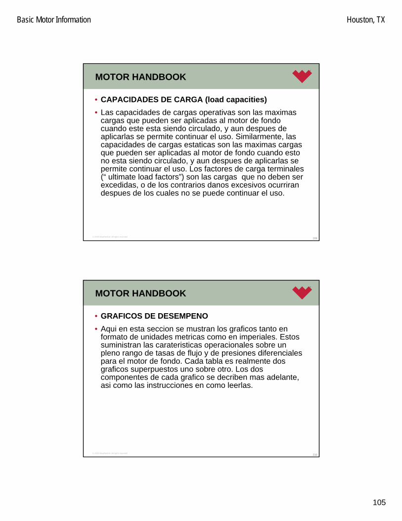
Basic Motor Information Houston, TX
105
209© 2005 Weatherford. All rights reserved.
MOTOR HANDBOOK
• CAPACIDADES DE CARGA (load capacities)• Las capacidades de cargas operativas son las maximas
cargas que pueden ser aplicadas al motor de fondocuando este esta siendo circulado, y aun despues de aplicarlas se permite continuar el uso. Similarmente, lascapacidades de cargas estaticas son las maximas cargasque pueden ser aplicadas al motor de fondo cuando estono esta siendo circulado, y aun despues de aplicarlas se permite continuar el uso. Los factores de carga terminales(“ ultimate load factors”) son las cargas que no deben ser excedidas, o de los contrarios danos excesivos ocurrirandespues de los cuales no se puede continuar el uso.
210© 2005 Weatherford. All rights reserved.
MOTOR HANDBOOK
• GRAFICOS DE DESEMPENO• Aqui en esta seccion se mustran los graficos tanto en
formato de unidades metricas como en imperiales. Estossuministran las carateristicas operacionales sobre un pleno rango de tasas de flujo y de presiones diferencialespara el motor de fondo. Cada tabla es realmente dos graficos superpuestos uno sobre otro. Los dos componentes de cada grafico se decriben mas adelante, asi como las instrucciones en como leerlas.

Basic Motor Information Houston, TX
106
211© 2005 Weatherford. All rights reserved.
MOTOR HANDBOOK
• RPM• El primero de los componentes en el grafico es la linea de
las RPM. A lo largo del fondo del grafico esta la presiondiferencial (kPa, psi). La presion diferencial es la diferencia entre los sistemas de presion cuando el motor/sarta se encuentra en fondo (bajo carga) y cuandose encuentra fuera de fondo (sin carga). En el ladoizquierdo del grafico esta la escala de la velocidad de rotacion (RPM).
212© 2005 Weatherford. All rights reserved.
MOTOR HANDBOOK
• RPM• Esta son las escalas para ser usadas cuando se use las
lineas de RPM horizontales en el grafico. Las lineashorizontales comienzan en el eje de la velocidad y comienzan a caer ligeramente segun la presion diferencialaumenta. Ellas eventualmente terminan en algun lugardonde se cruza con la linea vertical de plena carga “full load”. Estas lineas de RPM estan presentadas usualmentecomo dos set de a tres lineas cada uno, las cualescorresponden a diferentes tasas especificas de flujo o bombeo. La especificacion de la tasa de flujo puede ser vista legeramente encima de cada linea.

Basic Motor Information Houston, TX
107
213© 2005 Weatherford. All rights reserved.
MOTOR HANDBOOK
• RPM• Las lineas de RPM de color claro son las correspondientes
a los Motores de Nitrilo Estandar y termina justo al cruzar la linea vertical de Plena Carga para el Estandar Nitrilo.
• Las lineas de RPM de color oscuro son lascorrespondientes a los Motores de Nitrilo y termina justo al cruzar la linea vertical de Plena Carga del Premium Nitrile.
214© 2005 Weatherford. All rights reserved.
MOTOR HANDBOOK
• RPM• Las lineas de RPM se usan para determinar cual es la
RPM del motor de fondo, al saber cual es la tasa de flujo y la presion diferencial. Usando el Grafico de la Figura 4 para un Motor de Fondo de 6 3/4” (171 mm) PrecisionDrill™ LE6754-ML, si la tasa de flujo es 450 GPM (1.71 m3/min) y la presion diferencial es de 500 psi (3450 kPa), para un motor de estator de nitrilo estandar (lineaRPM de color claro) la velocidad de rotacion del motor de fondo seria aproximadamente de 117 RPM. Para tasas de flujo diferentes a las que se muestran en el grafico, se debe interpolar lineas entre las presentes, entonces la RPM puede ser leida.

Basic Motor Information Houston, TX
108
215© 2005 Weatherford. All rights reserved.
MOTOR HANDBOOK
• RPM - Imperial
• Figure 4: Performance Charts for a 6-3/4” (171 mm) PrecisionDrill™ Mud Lubricated Drilling Motor LE6754-ML.
DIFFERENTIAL PRESSURE (psi)
000
TORQUE20
RPM - 300 GPM
400 600
RPM - 450 GPM
RPM - 600 GPM
1000
100
200 800 1000
40
60
80
120
140
160
180
2000
3000
4000
5000
6000
7000
8000
9000
10000
FULL LOADSTANDARD NITRILE
FULL LOADPREMIUM NITRILE
200
4800
117
500
6-3/4” PrecisionDrillTM Drilling Motors LE6754-ML
216© 2005 Weatherford. All rights reserved.
MOTOR HANDBOOK
• RPM - Metrico
• Figure 4: Performance Charts for a 6-3/4” (171 mm) PrecisionDrill™ Mud Lubricated Drilling Motor LE6754-ML.
6500
3450DIFFERENTIAL PRESSURE (kPa)
000
TORQUE
1000
25 2000
50
75
175
4000
6000
8000
10000
12000
14000
100
125
150
2000 3000 4000 5000 6000 7000 8000
RPM - 2280 LPM
RPM - 1140 LPM
RPM - 1710 LPM
FULL LOADSTANDARD NITRILE
FULL LOADPREMIUM NITRILE200 16000
117
171mm PrecisionDrillTM Drilling Motors LE6754-ML

Basic Motor Information Houston, TX
109
217© 2005 Weatherford. All rights reserved.
MOTOR HANDBOOK
• RPM• El Grafico muestra que pasa con la velocidad del motor
con el incremento en la presion diferencial. En general unacaida en la RPM con el aumento en la presion diferenciales ligero hasta que la linea de plena carga/full load escruzada. En este punto la RPM cae rapidamente a zero, lo que representa el modo de estolamiento o represionamiento.
• Por consiguiente, es importante no ir mas alla de la maxima presion diferencial operativa recomendada, o el motor operara ineficientemente o un desgaste o danoprematuro ocurrira.
218© 2005 Weatherford. All rights reserved.
MOTOR HANDBOOK
• RPM• En adicion, este puede ser visto segun la presion
diferencial aumente, la linea curva de RPM del motor de estandar nitrile cae mas rapido que la del de premium nitrile. Esto indica que el motor de premium nitrile puedemantener su RPM mejor que el motor de estandar nitrile.

Basic Motor Information Houston, TX
110
219© 2005 Weatherford. All rights reserved.
MOTOR HANDBOOK
• TORQUE• El segundo componente del grafico es la linea de torque.
En el lado derecho de la tabla esta la escala de torque (ft-lbs, N-m). La linea de torque es usada con una escalacruzada con la presion diferencial que esta en el fondo. La linea de torque comienza en una presion diferencial de 0 y un torque de 0, y se incrementa linealmente segunaumenta la presion diferencial. La misma linea de torque es usada para varias tasas de flujo porque el torque esindependiente de la tasa de flujo. Esta linea de torque esla misma para ambos motores estandar o premium nitrile.
220© 2005 Weatherford. All rights reserved.
MOTOR HANDBOOK
• TORQUE• El torque output de un motor de fondo puede ser
determinado al conocer la presion diferencial a traves del motor. Usando los grafico de la Figura 4, si la presiondiferencial es 500 psi (3450 kPa), el output torque del motor es aproximadamente 4800 ft-lbs (6500 N-m).
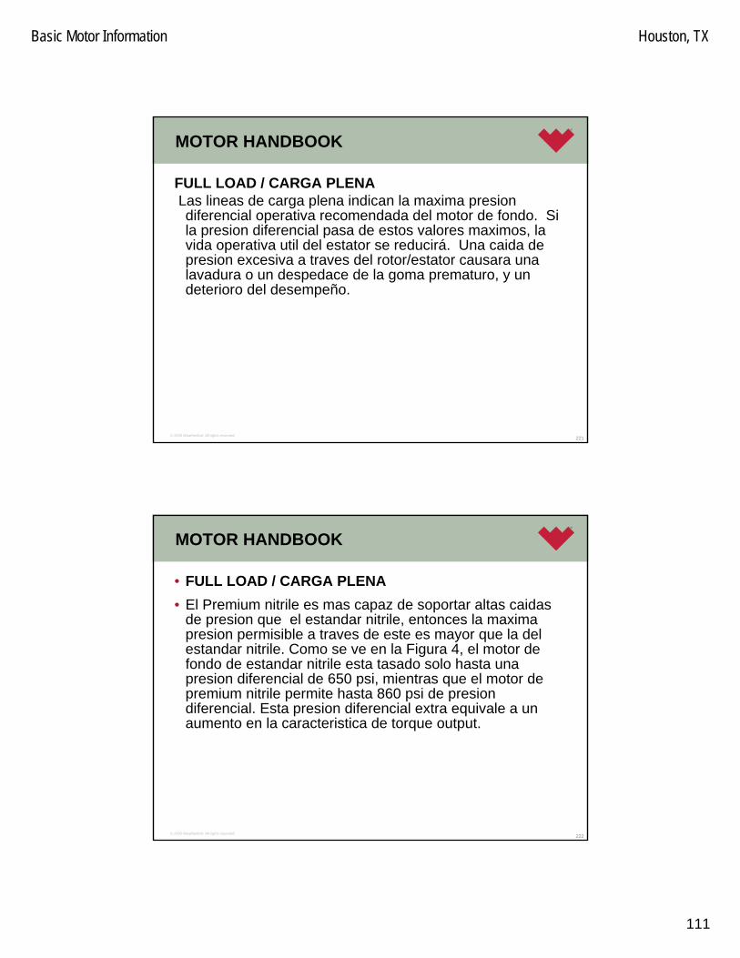
Basic Motor Information Houston, TX
111
221© 2005 Weatherford. All rights reserved.
MOTOR HANDBOOK
FULL LOAD / CARGA PLENALas lineas de carga plena indican la maxima presiondiferencial operativa recomendada del motor de fondo. Si la presion diferencial pasa de estos valores maximos, la vida operativa util del estator se reducirá. Una caida de presion excesiva a traves del rotor/estator causara unalavadura o un despedace de la goma prematuro, y un deterioro del desempeño.
222© 2005 Weatherford. All rights reserved.
MOTOR HANDBOOK
• FULL LOAD / CARGA PLENA• El Premium nitrile es mas capaz de soportar altas caidas
de presion que el estandar nitrile, entonces la maxima presion permisible a traves de este es mayor que la del estandar nitrile. Como se ve en la Figura 4, el motor de fondo de estandar nitrile esta tasado solo hasta unapresion diferencial de 650 psi, mientras que el motor de premium nitrile permite hasta 860 psi de presiondiferencial. Esta presion diferencial extra equivale a un aumento en la caracteristica de torque output.

Basic Motor Information Houston, TX
112
223© 2005 Weatherford. All rights reserved.
LOCALIZACION DE AVERIAS EN FONDO
• Una atencion de cuidado a las variaciones en la presiondel fluido puede servir para identificar muchos de los problemas de fondo. En muchos casos, las medidascorrectivas le pueden salvar de los costosos viajes. Seguido vemos los sintomas que muchas veces se experimentan durante la perforación, en conjunto con algunas de las causas possibles en referencia a los motores PrecisionDrill™. Tambien se listan las medidasque pueden ser tomadas para corregir el problema y continuar perforando.
224© 2005 Weatherford. All rights reserved.
LOCALIZACION DE AVERIAS EN FONDO
• NOTA: Cada vez que un problema ocurre mientras se perfora, fuertemente se sugiere que todos los posiblesproblemas de superficie sean identificados y corregidosantes de asumir que el problema esta relacionado con el equipo de fondo. Esto minimizara los tiempos de viajeinnecesarios para cambio de equipo de fondo.

Basic Motor Information Houston, TX
113
225© 2005 Weatherford. All rights reserved.
LOCALIZACION DE AVERIAS EN FONDO
• CON LA MECHA EN FONDO • (2) La presión de Circulación es mayor que la calculada.• A. El Drilling Motor o la Mecha se Taponan – Esto
usualmente coincide con poca o ninguna circulación. Unavez que se han chequeado y verificado todos los sistemashidráulicos es necesario sacar a superficie
• B. Sobrecarga Lateral Excesiva sobre la mecha debido a un hoyo por debajo del calibre o aun ajuste del bend housing grande – Esto usualmente coincide con circulación plena. Si el drilling motor esta muy ajustadocontra las paredes del hoyo, la mecha puede comenzar a desviar/sidetracking. Las medidad correctivas incluyenperforar el kelly down para reducir la carga lateral, o reducir el angulo del bend en el drilling motor. Si el sidetracking es un problema, el motor debe ser corrridocon una tasa de flujo menor para prevenir esto.
226© 2005 Weatherford. All rights reserved.
LOCALIZACION DE AVERIAS EN FONDO
• CON LA MECHA EN FONDO• (1) La presión de Circulación es menor que la calculada.• A. La válvula Dump Sub se atasca abierta – Encienda y
Apague las Bombas ( Flujo on / Flujo off ) para intentarcerrar la válvula. Use varias tasas de flujo. También, se puede reciprocar la tuberia una parada completa paraayudar a liberar la válvula. Si no se puede cerrar entonceses necesario sacar fuera del hoyo.
• B. Lavado en la Sarta / String Washout – Aplicaprocedimiento normal ante lavado de tuberia.
• C. Pérdida de la Circulación - Aplica procedimiento normal ante perdidas de circulación.

Basic Motor Information Houston, TX
114
227© 2005 Weatherford. All rights reserved.
LOCALIZACION DE AVERIAS EN FONDO
• CON LA MECHA EN FONDO• D. Desgaste o Daño al Stator – Con ciertos fluids de perf.,
los estatores podrian gastarse prematuramente, resultando en un debilitamiento notable en el uso. Segúnel estator se desgasta, la velocidad del drilling motor se reduce. Por consiguiente, un indicativo del desgaste del estator es la caida en la ROP, o un aumento en la presióndiferencial requerida para producir la misma ROP.
• E. Gas Kick / arremetida de gas – Procedimientos de arremetida de gas aplican.
228© 2005 Weatherford. All rights reserved.
LOCALIZACION DE AVERIAS EN FONDO
• La Presión de Circulación es mayor que la calculada.• A. El Drilling Motor o la Mecha se Tapan - Esto
usualmente coincide con una poca o ninguna circulación. Saque el WOB, permita a la mecha liberarse, y entoncespare las bombas. Si la presión se queda alta, es posibleque el drilling motor o todos los chorros (bit jets) estentaponados. Una vez que todos los sistemas hidráulicoshayan sido chequeados y verificados, podria ser necesariotener que sacar a superficie.

Basic Motor Information Houston, TX
115
229© 2005 Weatherford. All rights reserved.
LOCALIZACION DE AVERIAS EN FONDO
• La Presión de Circulación es mayor que la calculada.• B. Un recarga lateral excesiva de la mecha debido a un
hoyo con bajo calibre o debido a un motor con un arreglode bend elevado - Esto usualmente coincide con la circulación completa. Si el drilling motor esta muy ajustadocontra las paredes del agujero, el drilling motor podriatrabajar muy duro y el requerimiento de torque podria ser mayor al recomendado para las dimensiones OD de estemotor. Medidas Correctivas incluyen la reduccion del WOB o la reduccion del angulo de ajuste del bend del drilling motor.
230© 2005 Weatherford. All rights reserved.
Cambio o Pérdida en la tasa de penetración.
• La Presión de Circulación es mayor que la calculada.• C. El Drilling Motor Represionado o Represionandose -
Usualmente coincide con aumento de la presión. La Rotacion debe detenerse y cualquier torque en la sartaliberado. El WOB puede ser entonces reducidopermitiendo a la mecha aflojar y al motor girar libremente. Si la presión de bombas queda aún alta, las bombasdeben apagarse. Estos pasos deben seguirse en estasucessión obligada para reducir el daño potencial al estator.
• D. Mud Rings ( anillos de lodo) - Esto ocurre cuando los recortes se acumulan alrededor de la conección. Estocausa que la sarta se atasque y previene el deslizado. Use los procedimientos de tratamiento de lodo estandar.

Basic Motor Information Houston, TX
116
231© 2005 Weatherford. All rights reserved.
Cambio o Pérdida en la tasa de penetración.
• Cambio o Pérdida en la tasa de penetración. • A. Represionamiento del Drilling Motor - Usualmente
coincide con un incremento de presión. La Rotacion debepararse y cualquier torque en la sarta debe liberarse pocoa poco. El WOB se puede reducir permitiendo a la mechaaflojar y al motor a girar libremente. Si la presión de bombas sigue aún alta, Las bombas deben apagarseEstos pasos deben seguirse en esa sucessión obligadapara reducir el daño potencial al estator.
• B. Estator gastado – Referirse a la información antes mostrada del Estator Gastado bajo ‘La Presión deCirculación es menor que la calculada’.
232© 2005 Weatherford. All rights reserved.
LOCALIZACION DE AVERIAS EN FONDO
• Cambio o Pérdida en la tasa de penetración.• C. Cambio de Formación – Ajuste la tasa de flujo y el
WOB para optimizar el desempeño de la perforación paralas condiciones de la nueva formación.
• D. Sarta de Perforación / Colgamiento de Estabilizadores– Aplicar procedimientos correctivos normales.
• E. Desgaste de la Mecha y Embolamiento - Aplicarprocedimientos correctivos normales.

Basic Motor Information Houston, TX
117
233© 2005 Weatherford. All rights reserved.
LOCALIZACION DE AVERIAS EN FONDO
• Goma que aparece en los shale shakers• Chequear primeramente para asegurarnos que esta no
provenga de una fuente ajena al motor.• Una véz que la goma comienza aparecer en los shakers
esto no significa que el motor va a dejar de trabajar de inmediato. Usted va a observar una pérdida en el torque y la presión y por supuesto la ROP decaerá. Si esta cercade la zona objetivo seria provechoso consultar con el company man si le permite continuar en lugar de sacar del hoyo para cambiar el motor.
234© 2005 Weatherford. All rights reserved.
REPORTE DE FALLAS
• Sumario de Operaciones• Un total de 44 ft de side track fueron realizados en la
corrida anterior. Mientras se regresaba a fondo limpiandocon bombas despues de un viaje a superficie para cambiode, a una profundidad de 14,900ft M.D & temperatura de 302°F. De repente la presion de bombas se incrementó & y gran número de goma apareció en los shaker.
• El ajuste de rotor y estator para cada sección de poder fuehecho según el proceso estandar antes de armar la herramienta. Ambos estaban dentro de los limites de tolerancia. El arreglo de compresion era de .007 interferencia.

Basic Motor Information Houston, TX
118
235© 2005 Weatherford. All rights reserved.
REPORTE DE FALLAS
• La hoja de vida del Estator muestra Zero (0) hrs antes de la corrida:
236© 2005 Weatherford. All rights reserved.
REPORTE DE FALLAS
• Sumario del Taller• En el desarme de este motor el Bearing pack estaba en
buen estado. Sin embargo el Estator estaba en unacondición pésima. El estator era un nuevo relineado de ERT de R&M. Este tenio zero HRS previas & y solo acumuló 9.25 hrs en esta corrida antes de despedazarse
• A temperatura ambiente del taller el ajuste entre el Rotor & y el Estator fue de .007 Interferencia.
• Mirando a la carta de ajuste siguiente indica que la tolerancia de este arreglo estaba demasiado ajustada paraoperar a temperatura de 302°F para este estator en particular. El ajuste debe incrementarse aprox, .007 a .025 para una temp. operativa de 302°F. Esta interferenciademasiado ajustada entre el Rotor & Estator no permiteque suficiente flujo enfrie al elastómero causando calorexcesivo. Lo que provocó la falla del mismo.
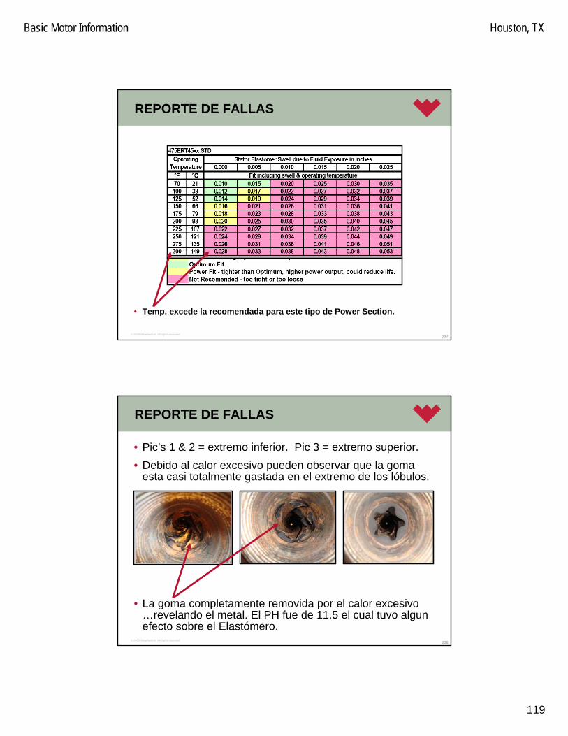
Basic Motor Information Houston, TX
119
237© 2005 Weatherford. All rights reserved.
REPORTE DE FALLAS
• Temp. excede la recomendada para este tipo de Power Section.
238© 2005 Weatherford. All rights reserved.
REPORTE DE FALLAS
• Pic’s 1 & 2 = extremo inferior. Pic 3 = extremo superior.• Debido al calor excesivo pueden observar que la goma
esta casi totalmente gastada en el extremo de los lóbulos.
• La goma completamente removida por el calor excesivo…revelando el metal. El PH fue de 11.5 el cual tuvo algunefecto sobre el Elastómero.

Basic Motor Information Houston, TX
120
239© 2005 Weatherford. All rights reserved.
REPORTE DE FALLAS
• El concepto basico de PH define la medida, en una escalalogarítmica de 1 a 14, de la acidéz relativa o de la alcalinidad una solución aquosa. Un pH Neutral (aguapura) es 7. El acido Hidrocloridico seria aproximadamente1 y el hidroxido de sodio de aproximadamente 13. Como regla de pulgar los valores de PH entre 5 y 8 no debetener efectos severos sobre los elastómeros nitrilicos.
• El efecto de un bajo PH (acido 0-7) o de un alto PH ( básico 7-14) es principalmente como catalizador de algunas reacciones quimicas que pueden conllevar a el hinchamiento o endurecimiento excesivos.
240© 2005 Weatherford. All rights reserved.
Diferentes ambientes que podrian causar fallas en el Estator:
• MECANISMOS DE FALLAS DEL ESTATOR• Mecánico y Fatiga• Térmico e Histeresis• Químico
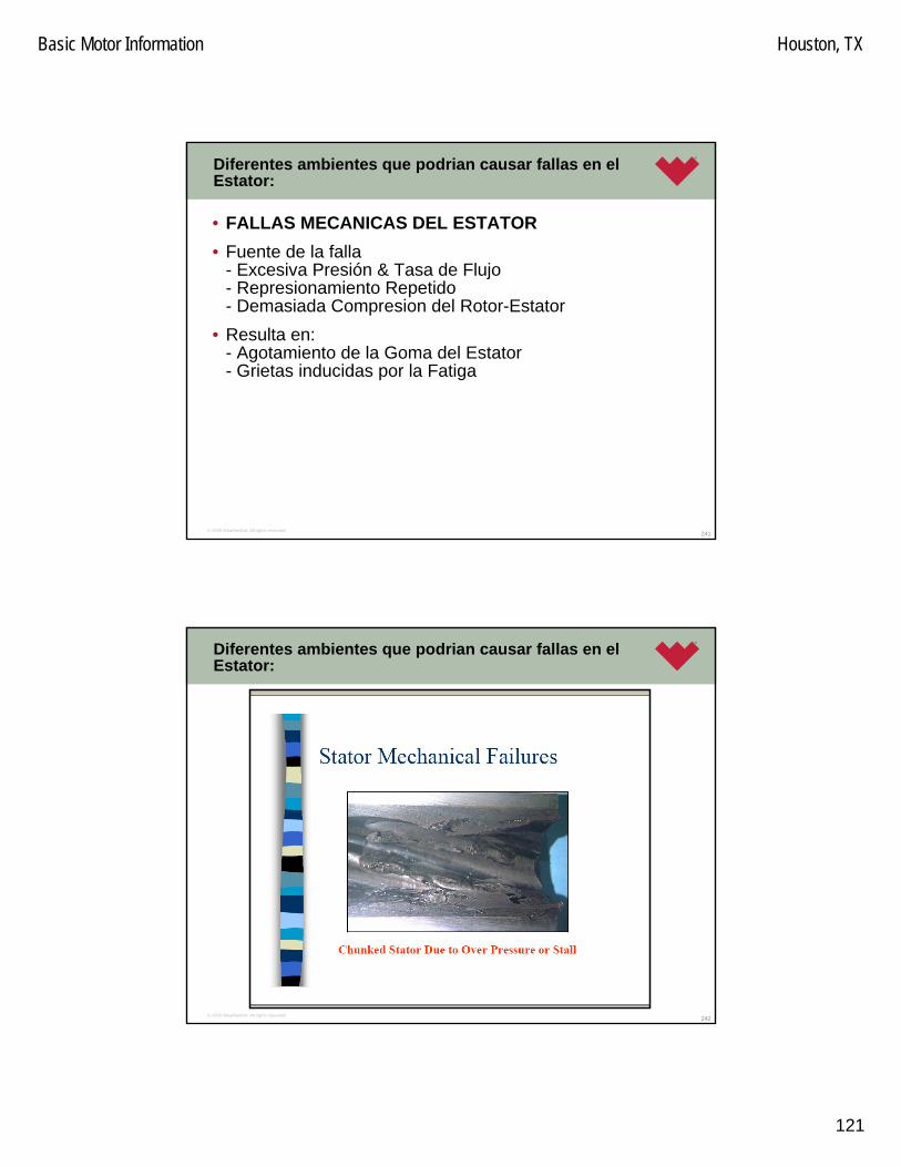
Basic Motor Information Houston, TX
121
241© 2005 Weatherford. All rights reserved.
Diferentes ambientes que podrian causar fallas en el Estator:
• FALLAS MECANICAS DEL ESTATOR • Fuente de la falla
- Excesiva Presión & Tasa de Flujo- Represionamiento Repetido- Demasiada Compresion del Rotor-Estator
• Resulta en:- Agotamiento de la Goma del Estator- Grietas inducidas por la Fatiga
242© 2005 Weatherford. All rights reserved.
Diferentes ambientes que podrian causar fallas en el Estator:

Basic Motor Information Houston, TX
122
243© 2005 Weatherford. All rights reserved.
Diferentes ambientes que podrian causar fallas en el Estator:
• FALLAS TERMICAS DEL ESTATOR• Fuentes
- Temperaturas de Fondo- Calor de la Histeresis / Hysteresis Heat
• Resulta en:- Debilitamiento de las propiedades del elastómero- Ajuste Compresivo Excesivo- Despedace del Estator/ Stator Chunking
244© 2005 Weatherford. All rights reserved.
Diferentes ambientes que podrian causar fallas en el Estator:

Basic Motor Information Houston, TX
123
245© 2005 Weatherford. All rights reserved.
Diferentes ambientes que podrian causar fallas en el Estator:
• FALLAS QUIMICAS DEL STATOR • Fuentes
- Fluidos de Perforación- Aceites Aromáticos (Azufre) / Sinteticos
• Resulta en:- Debilitamiento de la Cadena Molecular de la Goma- Hinchamiento o Encogimiento Volumétrico
246© 2005 Weatherford. All rights reserved.
Diferentes ambientes que podrian causar fallas en el Estator:

Basic Motor Information Houston, TX
124
247© 2005 Weatherford. All rights reserved.
Diferentes ambientes que podrian causar fallas en el Estator:
• OPTIMIZACION DE LA VIDA DEL ESTATOR • Reduzca la Presión Diferential
- Reducir el número de Represionamientos o Estolamiento• Correr a Baja Velocidad
- Mejora del Hysteresis- Alarga la Vida de Fatiga del Estator
• Seleccionar el Material Compatible del Estator- Reduce el Hinchado
248© 2005 Weatherford. All rights reserved.
Diferentes ambientes que podrian causar fallas en el Estator:

Basic Motor Information Houston, TX
125
249© 2005 Weatherford. All rights reserved.
Diferentes ambientes que podrian causar fallas en el Estator:
• Sumario de ideas• Las fuentes de Fallas del Estator son Mecánicas,
Térmicas, y Químicas• La vida del Estator se puede prolongar por medio de la
Optimización del Dideño y Aplicación.• La vida del Estator puede predecirse para diferentes
aplicaciones.
250© 2005 Weatherford. All rights reserved.
Diferentes ambientes que podrian causar fallas en el Estator:
• ACCION CORRECTIVA• Se recomienda que pidamos un ERT Rotor
undersized/subdimensionado si vamos a operar a Temperaturas de 300°F.

Basic Motor Information Houston, TX
126
251© 2005 Weatherford. All rights reserved.
TOOL WORKSHEETS & CALCULATIONS
• POPO Calculator
252© 2005 Weatherford. All rights reserved.
TOOL WORKSHEETS & CALCULATIONS
• POPO Calculator

Basic Motor Information Houston, TX
127
253© 2005 Weatherford. All rights reserved.
TOOL WORKSHEETS & CALCULATIONS
• POPO Calculator
254© 2005 Weatherford. All rights reserved.
TOOL WORKSHEETS & CALCULATIONS
• POPO Calculator

Basic Motor Information Houston, TX
128
255© 2005 Weatherford. All rights reserved.
TOOL WORKSHEETS & CALCULATIONS
• POPO Calculator
256© 2005 Weatherford. All rights reserved.
TOOL WORKSHEETS & CALCULATIONS
• MEDICION DEL RSS / WORKSHEET

Basic Motor Information Houston, TX
129
257© 2005 Weatherford. All rights reserved.
TOOL WORKSHEETS & CALCULATIONS
• MEDICION DEHERRAMIENTAS
258© 2005 Weatherford. All rights reserved.
TOOL WORKSHEETS & CALCULATIONS
• MEDICION DEHERRAMIENTAS

Basic Motor Information Houston, TX
130
259© 2005 Weatherford. All rights reserved.
TOOL WORKSHEETS & CALCULATIONS
• MEDICION DEHERRAMIENTAS
260© 2005 Weatherford. All rights reserved.
TOOL WORKSHEETS & CALCULATIONS
• MEDICION DEHERRAMIENTAS

Basic Motor Information Houston, TX
131
261© 2005 Weatherford. All rights reserved.
TOOL WORKSHEETS & CALCULATIONS
• MEDICION DE HERRAM.
262© 2005 Weatherford. All rights reserved.
Pregunta & Respuestas

1
STATOR LIFE OF A POSITIVE DISPLACEMENTDOWN-HOLE DRILLING MOTOR
R&M Energy SystemsA Unit of Robbins & Myers, Inc.
Conroe, Texas
ABSTRACTThe power section of a positive displacement drillmotor (PDM) consists of a steel rotor and a tubewith a molded elastomeric lining (stator). Powersection failures are typically due to the failure of thestator elastomer. Stator life depends on manyfactors such as design, materials of construction,and down hole operating conditions. This paperfocuses on the stator failure mechanisms and factorsaffecting stator life. An analytical method forpredicting the effect of various design and operatingparameters on the strain state and heat build-upwithin elastomers is discussed.
The effect of parameters such as rotor/stator design,down hole temperature, drilling fluid, statorelastomer properties, motor speed, and motordifferential pressure on the stator life is discussed.Non-linear finite element analysis is used toperform thermal and structural analysis on the statorelastomer. Data from laboratory accelerated lifetests on power section stators is presented todemonstrate the effect of operating conditions onstator life.
NOMENCLATURE
F loading frequency [Hz]G’ elastic modulus [psi]H hysteresis heat [BTU/hr-ft3]N number of rotor lobes∆P differential pressure across the
power section [dpsi]Q flow rate [gpm]S∆P slip or blow-by of fluid past seal lines.
A function of differential pressure acrossadjacent cavities. [number between 0 and 1]
T torque [ft-lb]Vc cavity volume; stator pitch x pumping
area [in3]W rotor speed [rpm]ε strain [in/in]tan δ ratio of viscous to elastic modulus
BACKGROUNDMud Motor Power SectionThe power section of a positive displacement drillmotor (PDM) converts the hydraulic energy of highpressure drilling fluid to mechanical energy in theform of torque output for the drill bit. A powersection consists of a helical-shaped rotor and stator.The rotor is typically made of steel and is eitherchrome plated or coated for wear resistance. The

2
stator is a heat-treated steel tube lined with ahelical-shaped elastomeric insert. Figure 1 is across-sectional view of a typical power section.
LOBE
CAVITIES
Figure 1. Cross-Sectional View of a 4:5 LobePower Section.
As shown in Figure 2, the rotors have one less lobethan the stators and when the two are assembled, aseries of cavities is formed along the helical curveof the power section. Each of the cavities is sealedfrom adjacent cavities by seal lines. Seal lines areformed along the contact line between the rotor andstator and are critical to power section performanceas will be discussed later.
ROTORS
STATORS
Figure 2. Various Lobe Configurations.
The centerline of the rotor is offset from the centerof the stator by a fixed value known as the“eccentricity” of the power section. When the rotorturns inside the stator, its center moves in a circularmotion about the center of the stator. Rotation ofthe rotor about its own axis occurs simultaneouslybut it is opposite to the rotation of the rotor centerabout the stator center. Figures 3 and 4 illustrate
two positions of a power section rotor within itscorresponding stator.
Figure 3. Rotor with Lobe “A” Fully Insertedin Stator Lobe.
Figure 4. Rotor Position Rotated Approximately20 Degrees from Position in Figure 3.
During drilling operations, high pressure fluid ispumped into the top end of the power section whereit fills the first set of open cavities. The pressuredifferential across two adjacent cavities forces therotor to turn and as this occurs, adjacent cavities areopened allowing the fluid to flow progressivelydown the length of the power section. Opening andclosing of the cavities occur in a continuous,pulsationless manner causing the rotor to rotate at aspeed that is proportional to drilling fluid flow rate(Equation 1). This action converts fluid hydraulicenergy into mechanical energy. As shown inEquation 2, the torque of a power section isproportional to cavity volume and differentialpressure across the power section.

3
W = [231*Q/ (N * Vc)]*S∆P (1)
T = (N*Vc*∆P)/24π (2)
Cavity volume is purely a function of power sectiondesign. As shown above, it is defined as pumping(cavity cross sectional) area multiplied by statorpitch. Moineau theory defines the maximumpumping area that can be obtained within a givenstator tube diameter. Power section speed isinversely proportional to stator pitch length. Figure5 illustrates the effect of pitch length on rotor speedat a given fluid flow rate.
0
0.2
0.4
0.6
0.8
1
1 2 3 4 5
NORMALIZED STATOR PITCH
NO
RM
AL
IZE
D
RO
TO
R S
PE
ED
4:5 LOBE
Figure 5. Reduction in Rotor Speed withIncreasing Stator Pitch.
Pressure Rating and SlipThe recommended differential pressure of a powersection is the summation of the pressure ratings foreach individual stage. Although the definition of astage is somewhat arbitrary, it is typically defined asone pitch length of the stator. The pressuredifferential rating for an individual stage generallyranges from 100 to 300 dpsi and depends on numberof lobes, pitch length, compression fit, andelastomer physical properties. For a power section,at otherwise identical conditions, higher pressureper stage usually means lower stator life. This willbe discussed later.
The pressure rating is the differential pressure atwhich a power section should operate to achieveoptimum stator life. However, it is not uncommonduring aggressive drilling to run power sectionswell above the maximum pressure rating. In manycases users will target operation at differentialpressures just below stalling conditions. Thispractice does result in significant reduction of statorlife.
Slip is caused when high pressure fluid blows byrotor and stator seal lines. Slip results in powersection speed reduction and is defined as the percentreduction in rotor speed below maximum theoreticalfor a given flowrate. The following tablesummarizes the impact of different design andoperating parameters on power section slip.
Table I. Parameters Affecting Slip.
Parameter Effect on SlipPressure differential increase IncreaseCompression fit increase DecreaseRubber modulus increase DecreaseFlow rate increase No changeRotor/Stator wear IncreaseStator expansion due totemperature or chemical swell
Decrease
During drilling, differential pressure and slipincrease as the load on the bit increases. This causesthe rotor speed to slow down until at some pointabove maximum rated pressure, the power sectionstalls. Once the motor is stalled, all drilling fluidblows by the seal lines. The differential pressure atwhich stall is reached can be increased byincreasing compression fit between the rotor andstator. Figure 6 shows the impact of a large fitvariation on power section speed and torque output.If the rotor-stator fit becomes too tight, stator lifewill be significantly reduced. Optimal fit provides aslip efficiency that is a compromise of stall marginat maximum rated pressure and stator life.

4
0
0.1
0.2
0.3
0.4
0.5
0.6
0.7
0.8
0.9
1
0 0.2 0.4 0.6 0.8 1
NORMALIZED DIFFERENTIAL PRESSURE
NO
RM
AL
IZE
D R
OT
OR
SP
EE
D
0
0.1
0.2
0.3
0.4
0.5
0.6
0.7
0.8
0.9
1
NO
RM
AL
IZE
D T
OR
QU
E
TIGHT
LOOSE
SPEED
TORQUE
Figure 6. Effect of Fit on Power SectionPerformance.
Figures 7 and 8 are performance charts for a typicalpower section. As the load on bit is increased, thedifferential pressure across the power section andtorque output increase while the rotor speeddecreases. The full load curve represents themaximum recommended differential pressure atwhich the power section should be operated. Notethat the pressure rating decreases as flow rate androtor speed increase. The reason for derating apower section is to achieve longer life. This will beexplained in more detail later.
0
50
100
150
200
250
0 100 200 300 400 500
DIFFERENTIAL PRESSURE (PSI)
RO
TO
R S
PE
ED
(
RP
M)
INCREASING FLOWRATE
MAX ∆P LINE
Figure 7. Typical Power Section Performance.
050
100150200250300350400450
0 100 200 300 400 500
DIFFERENTIAL PRESSURE (PSI)
TO
RQ
UE
(F
T-L
B) EFFECTIVE ∆P
OFF-BOTTOMPRESSURE LOSSES
INCREASING FLOWRATE
Figure 8. Typical Power Section Performance.
Figure 8 shows that torque output of a powersection increases essentially linearly with increasingdifferential pressure across a power section. Thepressure losses shown are the combined effects offlow losses in the entrance region of the powersection and of frictional losses between the rotorand stator. The losses are quantified as thedifferential pressure required to start the rotorturning and are dependent on drilling fluid flowrate.In the example above, the losses range from 50 psiat the lowest flowrate to 120 psi at the highestflowrate. The differential pressure needed for start-up does not contribute to torque generation by thepower section. For example, if a power section isoperated at 400 psi differential pressure and thestart-up differential pressure is 100 psi, thedifferential pressure that is effectively generatingpower is 300 psi.
FAILURE MECHANISMSOne of the most challenging aspects of utilizingpower sections for drilling operations isunderstanding and predicting failure. Power sectionfailures are primarily due to destruction of the statorelastomer. Rotor failures due to wear or chemicalattack are rare compared to stator failures and arenot discussed in this paper. Elastomer failures maybe classified as those which result in a reduction inperformance and those which are catastrophic. In

5
many cases continued operation under conditions ofreduced performance will lead to catastrophicfailure. Each type of failure may be caused by avariety of reasons. In the following sections, keystator failure mechanisms and the factors thatinfluence them are categorized.
Mechanical and FatigueMechanical failure of the stator elastomer occurswhen the elastomer is overloaded beyond its stressand strain limits. Any number of the followingfactors may contribute to premature statormechanical failures: 1) excessive pressure duringaggressive drilling operations; 2) repeated stalling;or 3) high compression fit between rotor and stator.Each of these factors results in overstrain of thestator lobes beyond their mechanical limits. Figure9 is an illustration of a stator that failed under highmechanical loading.In some cases, power section stators can fail due tofatigue at mechanical loading conditions well belowthe rubber tear strength.
Figure 9. Chunked Stator Due to Overpressure.
Fatigue failures are the result of high cyclic loadingon the stator elastomer due to rotor speed. Equation3 defines the loading frequency for a power sectionstator.
F = (RPM/60)* N (3)
The cyclic loading simply defines the number oftimes a stator lobe is flexed in a unit of time. As the
number of power section lobes increases, fatiguelife decreases because the loading frequencyincreases. One method for compensating for this isto reduce rotor speed. At high loading frequencies,the strain and strain rates on the elastomer will besufficient to promote the initiation and propagationof microscopic cracks in the stator lobes. Thisphenomenon, known as fatigue crack growth,occurs under high strain and strain rate dependingon the elastomer tear strength and strain energyrelease rate. If the elastomer is subjected to strainbelow the critical level, the onset of fatigue crackgrowth may not occur even at very high frequencies.However, at strains above the critical level, crackswill initiate in the high strain region, usually in thebottom of the stator lobes, and the crack growth ratewill depend on the cyclic rate of loading. Figure 10illustrates failure of a stator operated above thecritical strain level for a given loading frequency.
Figure 10. Failed Stator Due to FatigueCrack Growth.
Thermal and Hysteresis FailuresThermal failures occur when stator elastomertemperature exceeds its rated temperature for aprolonged duration. Stator elastomer physicalproperties usually weaken as temperature increases.The weakening of the elastomer properties results inshortened stator life. High elastomer temperatures
FATIGUECRACKS ATBOTTOMOF LOBES

6
may be due to down-hole temperature, hysteresisheat, or the combination of both.
Exposure to the down-hole temperature will causethe stator elastomer to expand which tightenscompression fit. Degradation of elastomer physicalproperties will occur if the down-hole temperatureis above the temperature rating of the elastomer.
Hysteresis heat generation is due to repeated flexingof the stator lobes by the rotor and the pressurizedfluid. Because elastomers are visco-elasticmaterials, a portion of the flexing energy isconverted into thermal energy. Equation 4 fromReference 1 can be used to estimate hysteresis heatgeneration within elastomers.
H = 2100* G’ * tan δ *ε2 * F (4)
The location of peak hysteresis heat build-up is nearthe center of the stator lobes. The strain in thisregion combined with the low thermal conductivityof elastomers result in this heat build-up. Figure 11shows the temperature distribution within a typicalstator due to hysteresis heat build-up. Note the 30degree F temperature build-up due to hysteresis.The heat build-up increases as power section speed,pressure differential, or compression fit is increased.The maximum temperature within the stator mayexceed the elastomer’s temperature rating, even ifthe down-hole temperature is well within theoperating limits of the stator. Therefore, at elevateddown-hole temperatures, power section life may beprolonged if the power sections are operated at slowspeed or low differential pressure.
Figure 11. Hysteresis Heat Build-up WithinStator Elastomer.
In all the cases described above, the result ofelastomer temperature exceeding its temperaturerating is: 1) the reduction of elastomer physicalproperties; and 2) the expansion of the elastomerwhich tightens rotor/stator compression fit. Thecombined thermal and mechanical effectssignificantly reduce stator life. Using an oversizestator is one method for compensating for increasedfit due to elastomer expansion.
Chemicals and AromaticsDrilling fluids are composed of many differentchemicals and are uniquely designed to improvedrilling penetration rate, prevent formation damage,allow easy clean-up, and facilitate other drillingrequirements. Some of the chemicals, syntheticoils, or aromatics used in drilling fluids weaken therubber molecular chain resulting in reduction inrubber physical properties and shrinkage or swell.Weakening of the rubber combined with a change incompression fit due to shrinkage or swell willaccelerate stator failure. Figure 12 shows an
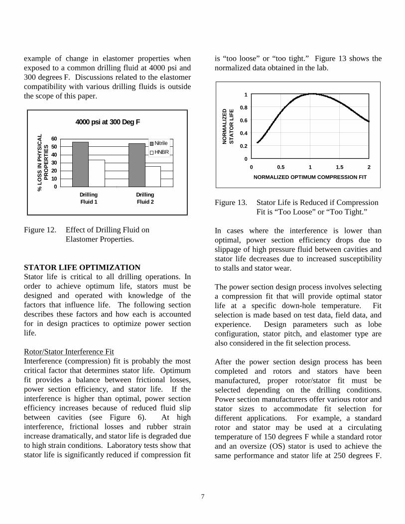
7
example of change in elastomer properties whenexposed to a common drilling fluid at 4000 psi and300 degrees F. Discussions related to the elastomercompatibility with various drilling fluids is outsidethe scope of this paper.
4000 psi at 300 Deg F
0102030405060
DrillingFluid 1
DrillingFluid 2
% L
OS
S IN
PH
YS
ICA
L
PR
OP
ER
TIE
S
Nitrile
HNBR
Figure 12. Effect of Drilling Fluid onElastomer Properties.
STATOR LIFE OPTIMIZATIONStator life is critical to all drilling operations. Inorder to achieve optimum life, stators must bedesigned and operated with knowledge of thefactors that influence life. The following sectiondescribes these factors and how each is accountedfor in design practices to optimize power sectionlife.
Rotor/Stator Interference FitInterference (compression) fit is probably the mostcritical factor that determines stator life. Optimumfit provides a balance between frictional losses,power section efficiency, and stator life. If theinterference is higher than optimal, power sectionefficiency increases because of reduced fluid slipbetween cavities (see Figure 6). At highinterference, frictional losses and rubber strainincrease dramatically, and stator life is degraded dueto high strain conditions. Laboratory tests show thatstator life is significantly reduced if compression fit
is “too loose” or “too tight.” Figure 13 shows thenormalized data obtained in the lab.
0
0.2
0.4
0.6
0.8
1
0 0.5 1 1.5 2
NORMALIZED OPTIMUM COMPRESSION FIT
NO
RM
AL
IZE
D
ST
AT
OR
LIF
E
Figure 13. Stator Life is Reduced if CompressionFit is “Too Loose” or “Too Tight.”
In cases where the interference is lower thanoptimal, power section efficiency drops due toslippage of high pressure fluid between cavities andstator life decreases due to increased susceptibilityto stalls and stator wear.
The power section design process involves selectinga compression fit that will provide optimal statorlife at a specific down-hole temperature. Fitselection is made based on test data, field data, andexperience. Design parameters such as lobeconfiguration, stator pitch, and elastomer type arealso considered in the fit selection process.
After the power section design process has beencompleted and rotors and stators have beenmanufactured, proper rotor/stator fit must beselected depending on the drilling conditions.Power section manufacturers offer various rotor andstator sizes to accommodate fit selection fordifferent applications. For example, a standardrotor and stator may be used at a circulatingtemperature of 150 degrees F while a standard rotorand an oversize (OS) stator is used to achieve thesame performance and stator life at 250 degrees F.

8
Oversize stators are also utilized when using drillingfluids that are known to cause elastomer swell.
Accurate measurements of rotor and stator sizes areimportant in power section fit selection. Variationsin stator sizes of as little as 0.005-0.010 inches canresult in significant changes in performance andstator life. Accurate measurement of stator profilesize and shape is extremely difficult because: 1)there are size changes with variations in ambienttemperature and humidity; 2) the internal geometryof the stator is complex; 3) the elastomer flexesduring measurement; and 4) measurementtechniques vary. Most manufacturers of powersections provide rotor and stator dimensions so thatthe operators can match the rotor and stator toachieve the desired fit for the particular application.
Operating ConditionsRunning a power section at or below maximumrecommended pressure is the primary operationalconsideration that must be made to maximize statorlife. Excessive differential pressure during drillingcauses extreme deformation of the stator lobesresulting in premature mechanical failures.
Consideration must also be made during drillingoperations for rotor speed. As shown in Figure 7,the differential pressure rating for a power sectiondecreases as rotor speed (flow rate) increases. Thereason power section pressure differential isderated with increasing rotor speed is to offset theeffect of increased rubber strain rates. If themaximum pressure rating is not derated at highrotor speed, stator life will be reduced.
ElastomersPower section stators are commonly made withnitriles (NBR) because of their excellent physicalproperties and oil resistance. Nitrile rubbers (NBR)are manufactured by copolymerization of butadienewith acrylonitrile (ACN). Typical stator rubbercompound consists of a nitrile base polymer,reinforcing materials, curatives, accelerators, and
plasticizers. Rubber compound formulations areproprietary to power section manufacturers and aredesigned to address different applications.
The majority of stator elastomer properties aredetermined by the base polymer used in thecompound. All nitrile polymers are prepared withvarying ratios of ACN. The amount of oil andsolvent resistance is based on the ACN content ofthe polymer. Compounds with 25 to 35 percentACN content are “medium”, and compounds with35 to 50 percent ACN are known as “high” ACNcompounds.
Hydrogenated nitriles (HNBR) are produced byintroducing hydrogen to dissolved nitrile elastomersto improve its physical properties. The HNBRproperties that are most relevant to power sectionstators are high tensile strength, high modulusretention at elevated temperatures, high hot tearresistance, improved oil and solvent resistance overNBRs, and heat resistance. The hydrogenation levelof an HNBR varies from 80 to 99 percent. HNBRswith 90 percent or higher hydrogenation aresometimes referred to as Highly Saturated Nitrilesor HSN.
A stator rubber compound is designed for differentdrilling applications. Typically, HSNs are used forhigh temperature applications and high ACNcompounds are used for applications with morearomatic oil-based drilling fluids. Compound designwill determine rubber properties such as tensilestrength, hysteresis heat build-up, fatigue life, andmodulus retention all of which are critical to apower section’s operation and life.
ANALYTICAL MODELLINGThe following section describes a method forpredicting stator life under various operationalconditions. The results may be used as a guidelineto maximize stator life.
Analytical technique for stator life prediction

9
A non-linear finite element analysis (FEA) approachcan be used to predict the elastomer strain levels ofa typical power section with various interferencefits, at different operational and down-holeconditions, and for different rotor positions withinthe stator. The calculated strain state can then beutilized as input for predicting hysteresis heat build-up within the elastomer. Earlier work (Delpassand,1995) describes the two-part analysis used tocalculate heat build-up within stator elastomers.
Figure 14. Life Prediction Analysis Flow Chart.
Next, empirical data may be employed to determinethe physical property reduction of an elastomer astemperature increases. Finally, an estimate of statorlife can be made based on the stress and strain of theelastomer at the temperature generated within thecenter of the stator lobes.
At the strain levels encountered in the statorelastomer at down-hole conditions, the materialproperties are non-linear. This is shown inDelpassand (1995). Therefore, use of non-linearelastomer properties as determined throughlaboratory testing is important in order to achieveaccurate results.
To conduct FEA, geometrical and thermal boundaryconditions must be simulated. The structuralboundary conditions imposed on the statorelastomer are compression fit between the rotor andstator, hydraulic pressure across the stator lobesfrom the drilling fluid, and elastomer-to-tube bond.Radial forces caused by the eccentric motion of therotor can be ignored for smaller power sections.
The thermal boundary conditions on the stator areforced convection between the drilling fluid and theinternal surfaces of the stator and the tube outsidewall. Hysteresis heat input to the elastomer iscalculated using Equation 4.
ResultsThe following section provides an example of thestator life prediction method described above.Table II lists the selected operating conditions forthe analysis.
Table II. Example Operating Conditions.
PARAMETERElastomer Typical NitrileAmbient Compression Fit [in] 0.010Circulating Temp [degrees F] 150Rotor Speed [rpm] 250Differential Pressure perStage [psi]
125
Figure 15 illustrates the predicted strain state in theelastomer of a 5-lobe stator at the down-holeoperating conditions in Table II and with the rotorin the top dead center (TDC) position. For thepurpose of analysis, the rotor position whichresulted in the highest strain levels was utilized inheat generation predictions.
OperatingConditions
DesignParameters
ElastomerStrain andStrain Rate
HysteresisHeat Build-
up
MechanicalStrain and
Stress
EmpiricalLife
Prediction
LaboratoryData
Iterations
Iterations

10
Figure 15. Strain State with Rotor in TDCPosition. Lighter Sections ShowHigher Strain.
Figure 16. Elastomer Deflection with RotorPosition 15degrees from TDC.
Figure 16 shows the rubber deflection and strain atthe above conditions but with the rotor positioned15 degrees from TDC.
Figure 11 illustrates the predicted temperaturedistribution within the stator elastomer at theselected conditions. In the example given, the
temperature within the center of the stator lobes is30 degrees higher than the circulating temperature.
The foregoing figures illustrate the effect of designand operating conditions on the heat generationwithin the elastomer of a stator. Figure 17 showsthe strain-energy capability of a typical nitrile as afunction of elastomer temperature. Strain energy isdefined as the area under the rubber stress-straincurve.
0
100
200
300
400
500
150 200 250 300
TEMPERATURE (F)
ST
RA
IN E
NE
RG
Y (
KP
SI)
Nitrile
HNBR
Figure 17. Elastomer Strain Energy Capability.
Finally, knowledge of elastomer strain energyreduction due to temperature can be correlated tostator life. Table III shows an example of stator lifeprediction data for a 6.75” diameter 4:5 lobe powersection. In the cases selected, FEA was used topredict the rubber strain and temperature build-up atvarious circulating temperatures, pressures perstage, and rotor speeds. The predicted maximumstator temperature was then used in conjunctionwith Figure 17 to determine the rubber strainenergy. Finally, the results were correlated withstator life test data collected under the first set ofconditions in Table III. The analysis does notinclude the impact of drilling fluid compatibility orany other specific operating conditions.
High strainregion wherefatigue crackstypically form.
Elastomerdeflection dueto compression.

11
Table III. Life Prediction For 6.75” 4:5 Lobe.
Circulating Temperature
(F)
Pressure per Stage
(PSI)
Rotor Speed (RPM)
Maximum Stator
Temp (F)
Normalized Rubber Strain
Rubber Strain
Energy (KPSI)
Normalized Stator Life
Stator Life Estimates
(hours)150 100 400 238 1 125 1 500200 200 400 344 2.3 49 0.17 87200 100 600 332 1.2 52 0.33 167250 100 400 338 1.3 51 0.31 154
The figures 18 and 19 illustrate a few of the testresults recently obtained in the laboratory. Thefigures show the effect of rotor speed anddifferential pressure on heat build-up within theelastomer.
60
70
80
90
100
110
120
0 200 400 600 800 1000ROTOR SPEED (RPM)
EL
AS
TO
ME
R
TE
MP
(F
)
Figure 18. Heat Generation Due to Rotor Speed.
7:8 LOBE, 450 GPM
0
20
40
60
80
100
120
0 100 200 300 400 500 600 700 800
DIFFERENTIAL PRESSURE (PSI)
ST
AT
OR
TE
MP
IN
CR
EA
SE
(F
)
TEST DATA
Figure 19. Heat Generation Due toDifferential Pressure.
CONCLUSIONSPower section stators typically fail due to highmechanical loading, fatigue, drilling fluid
incompatibility, or high temperature. Mechanicalfailures occur when the stator elastomer isoverloaded beyond its stress and strain levels.Excessive pressures, repeated stalls, or too muchcompression between rotor and stator result in amechanical failure. Fatigue failures occur whenelastomer strains are above critical limits and thestator lobes are subject to high cyclic loading.Cracks due to fatigue are often initiated in thetransition between the crests and valleys of thestator lobes and lead to stator failure. Some of thechemicals and oils used in drilling fluids change thephysical properties of the stator elastomers.Weakening of the rubber combined with a change inthe compression fit due to shrinkage or swell willaccelerate stator failure. High temperature is one ofthe most important parameters leading to a powersection stator failure. High elastomer temperaturesare due to down-hole conditions, hysteresis heatbuild-up, or the combination of both. At elevatedtemperatures, elastomer properties are degraded andall failure modes are accelerated.
In order to maximize stator life, compression fitbetween the rotor and stator must be selected for thedown-hole conditions. In addition, power sectiondifferential pressure should be reduced as rotorspeed is increased to maintain stator life. Finally,the stator elastomer must be carefully selected toinsure compatibility with the drilling fluid.
REFERENCESDelpassand, Majid, 1995, “Mud Motor StatorTemperature Analysis Technique”, ASME DrillingTechnology, Book No. H00920.
200 psi
100 psi
50 psi
0 psi
4:5 LOBE