direction concealed thermostatic shower 2 kiri d, kiri da
TRANSCRIPT
Two Direction Concealed Thermostatic ShowerKAHA 2D, KAHA 2DA, KAHA 2DBK, KIRI 2D, KIRI 2DA, TUROA 2DInstallation Instructions & Maintenance Guide
Technical Specifications:
Supply:Suitable For All Pressure System
Working Pressure:0.2 - 5.0 bar
Operating Temperature:Hot: Max 65°CCold: Min 5°CInlet Connections:1/2" BSPCartridge/Valve Type: Thermostatic
TEL: 0800 195 1602FAX: +44 (0) 1942 680 190E: [email protected]
METHVEN UK LIMITED METHVEN EXPERIENCE CENTRE 3/3A STONE CROSS COURT YEW TREE WAYGOLBORNEWARRINGTONWA3 3JDUNITED KINGDOM
Your product has a high quality finish and should be treated with care to preserve the visible surfaces.
Never use abrasives or abrasive cleaning agents to clean this product. Clean regularly with contamination free warm soapy water and a damp soft cloth. Do not use products containing chlorine bleach or hydrochloric acid as these can damage the product. Always rinse the product thoroughly after cleaning to remove cleaning products that can damage the shower.
We have a policy of continuous improvement and reserve the right to change specifications without notice.
INST VARIETY 2D Valves 01.07.2020
www.methven.com
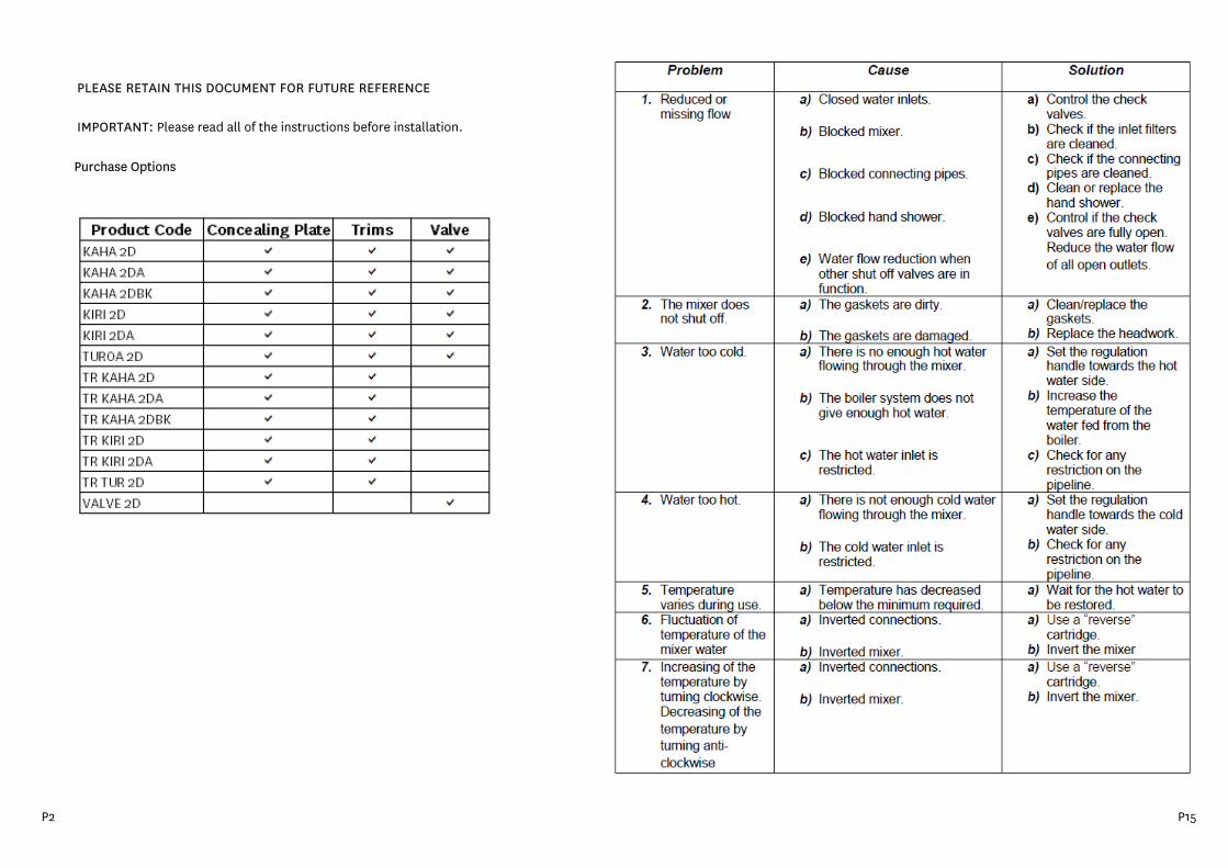
PLEASE RETAIN THIS DOCUMENT FOR FUTURE REFERENCE
IMPORTANT: Please read all of the instructions before installation.
Purchase Options
P2 P15
GENERAL CHARACTERISTICSThis valve is suitable for All Pressure heating systems.
Prior to installing your Thermostatic mixing valve it is important to fully understand the site installation conditions and the location where you intend to install your product. This Thermostatic mixing valve is designed to be used within the following systems:-
Gravity Fed Hot and ColdWherever possible for the best performance of the product, it is always best practice to have equal pressures supplied to both hot and cold inlets. However this product will only work up to a maximum 5 to 1 pressure differential.
Unvented SystemsPumped SystemsGas Combination Boiler
Your product should be fitted in compliance with the Water Authority Regulations. If you are unsure as to what the the regulations require, You can contact your Local Water Authority or the Insittute of Plumbers for further details.
OPERATING SPECIFICATIONS
Maximum Static Pressure - BarFlow Pressure, Hot & Cold - BarHot Supply Temperature - °CCold Supply Temperature - °C < 25°C
Low Pressure
10 bar
0.1 to 1
55°C to 65°C
< 25°C
10 bar0.5 to 5
High Pressure
55°C to 65°C
NOTE: Valves operating outside these conditions cannot be guaranteed by the scheme to operate as Type 2 valves.
The valves designation of use is for LP & HP (HP-S) (HP-T) BS EN1111 and (LP-S) (LP-T) BS EN1287 the recommended mixed water outlet for showers at point of discharge is 41°C
For gravity systems a minimum distance of 5 meters is required between the bottom of the storage tank and the shower head. Failure to ensure this criteria is met may cause the Thermostatic mixing valve to work incorrectly. If a water supply is fed by gravity then the supply pressure should be verified to ensure the conditions of use are appropriate for the valve. The check valves with strainers are inserted in the inlet connections in order to prevent back flow.
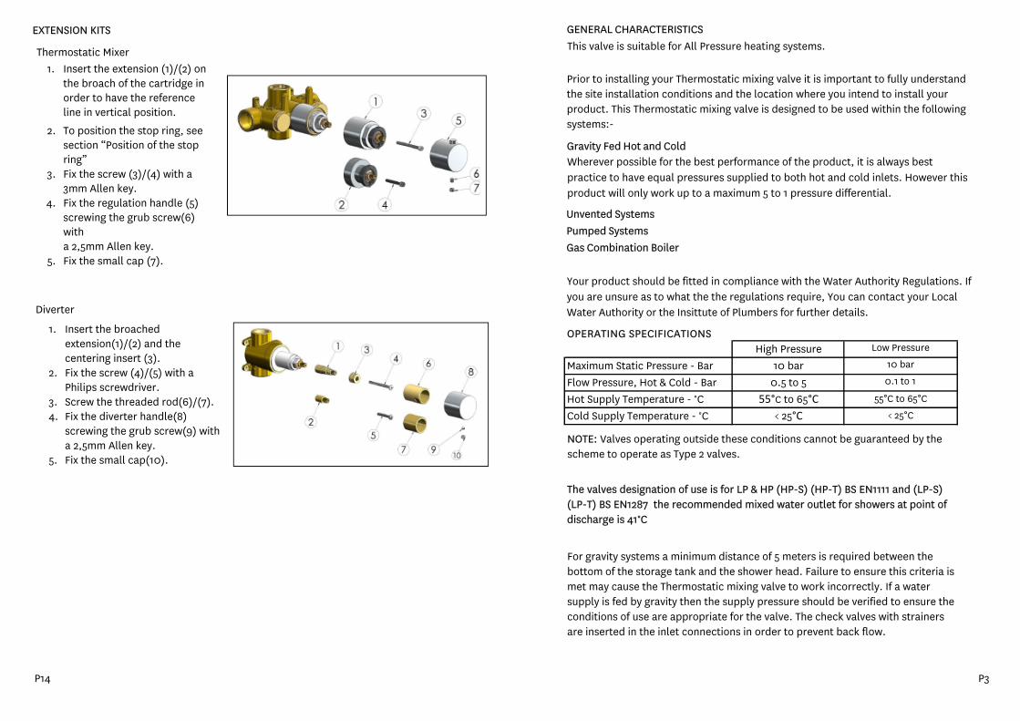
EXTENSION KITS
Thermostatic Mixer1. Insert the extension (1)/(2) on
the broach of the cartridge inorder to have the referenceline in vertical position.
2. To position the stop ring, seesection “Position of the stopring”
3. Fix the screw (3)/(4) with a3mm Allen key.
4. Fix the regulation handle (5)screwing the grub screw(6)witha 2,5mm Allen key.
5. Fix the small cap (7).
Diverter
1. Insert the broachedextension(1)/(2) and thecentering insert (3).
2.
3.4.
Fix the screw (4)/(5) with aPhilips screwdriver.Screw the threaded rod(6)/(7).Fix the diverter handle(8)screwing the grub screw(9) witha 2,5mm Allen key.
5. Fix the small cap(10).
P14 P3
RECOMMENDED OUTLET TEMPERATURES
The NSF TMV Scheme recommends the following set maximum mixed water outlet temperatures for use in all premises:
44°C for bath fill but see notes below;41°C for showers41°C for washbasins38°C for bidetsThe mixed water temperature must never exceed 46°C
The maximum mixed water temperature can be 2°C above the recommended maximum set outlet temperatures.
NOTE:46°C is the maximum mixed water temperature from the bath tap. The maximum temperature takes account of the allowable temperature tolerances inherent in the thermostatic mixing valves and temperature losses in metal baths.
It is not a safe bathing temperature for adults or children.The British Burns Association recommends 37°C to 37.5°C as a comfortable bathing temperature for children. In premises covered by the Care Standards Act 2000, the maximum mixed water outlet temperature is 43°C.
The thermostatic mixing valve should be installed in such a position that maintenance of the TMV and its valves and the commissioning and testing of the TMV can be undertaken.
The fitting of isolation valves is required as close as is practicable to the water supply inlets of the thermostatic mixing valve.
1234
5 Isolate both the hot and cold water supplies
Check the contents of the box and all parts are present and correct. Check to ensure the minimum operating conditions can be met. The correct tools to perform a trouble free installation Considered the surrounding environment where the installation is to take place and any potential hidden dangers.
Important points to note before commencing installation of your concealed shower mixer. You should have:-
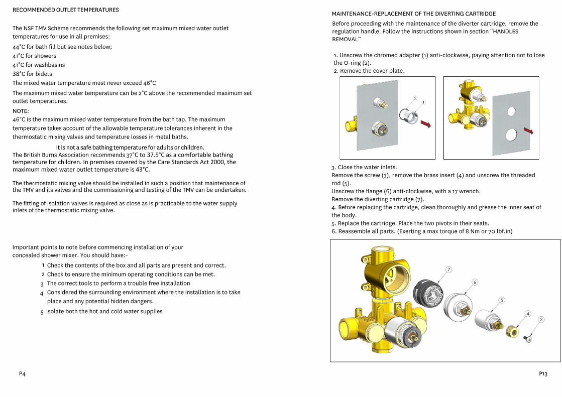
MAINTENANCE-REPLACEMENT OF THE DIVERTING CARTRIDGEBefore proceeding with the maintenance of the diverter cartridge, remove the regulation handle. Follow the instructions shown in section “HANDLES REMOVAL”
1. Unscrew the chromed adapter (1) anti-clockwise, paying attention not to losethe O-ring (2).2. Remove the cover plate.
3. Close the water inlets.Remove the screw (3), remove the brass insert (4) and unscrew the threadedrod (5).Unscrew the flange (6) anti-clockwise, with a 17 wrench.Remove the diverting cartridge (7).4. Before replacing the cartridge, clean thoroughly and grease the inner seat ofthe body.5. Replace the cartridge. Place the two pivots in their seats.6. Reassemble all parts. (Exerting a max torque of 8 Nm or 70 lbf.in)
P4 P13
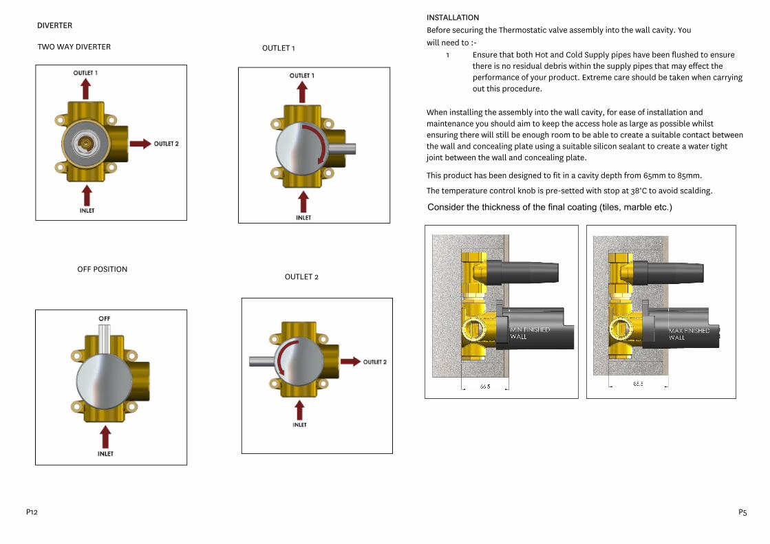
INSTALLATIONBefore securing the Thermostatic valve assembly into the wall cavity. You will need to :-
1 Ensure that both Hot and Cold Supply pipes have been flushed to ensure there is no residual debris within the supply pipes that may effect the performance of your product. Extreme care should be taken when carrying out this procedure.
When installing the assembly into the wall cavity, for ease of installation and maintenance you should aim to keep the access hole as large as possible whilst ensuring there will still be enough room to be able to create a suitable contact between the wall and concealing plate using a suitable silicon sealant to create a water tight joint between the wall and concealing plate.
This product has been designed to fit in a cavity depth from 65mm to 85mm.
The temperature control knob is pre-setted with stop at 38°C to avoid scalding.
Consider the thickness of the final coating (tiles, marble etc.)
DIVERTER
TWO WAY DIVERTER OUTLET 1
OFF POSITIONOUTLET 2
P12 P5
1. Ensure that both the Hot and Cold mains water supplies are isolated.
2. Fix the shower valve assembly into the wall cavity ensuring the thermostaticmixing valve is at the bottom and the diverter assembly is at the top. If donecorrectly the 'Hot' inlet port to the Thermostatic mixing valve will be at thebottom of the valve assembly to the left hand side.
3. Connect the respective Hot and Cold water supplies to the Hot and Cold inletports of the Thermostatic mixing valve making sure that all seals, filters, olivesare fitted and joints sufficiently tightened.
4. Connect the pipework for the shower fitting to the outlet.
IMPORTANT : Before fitting the concealing plate it is essential that all joints are
checked for leaks. Failure to do so could result in flooding or water damage
within the cavity over a long period of time that may not be immediately
evident. Therefore:-
5. Secure the flow control knob to the flow control valve6. Secure the temperature control knob to the thermostatic mixing valve, to
secure the temperature knob in the correct position, Please refer to'Maximum temperature setting and adjustment'
7. Ensuring all joints have been secured and tightened, turn on both Hot andCold water supplies.
8. Turn the flow control knob9. Taking care, turn the thermostatic mixing valve on, whilst water should now be
flowing through the outlet, check all joints for signs of leaks. Turn off thethermostatic mixing valve and repeat the process for the remaining connectedoutlet. Any leaking joints should be immediately rectified. It may be a goodidea to leave the shower running for several minutes to ensure the joints arewater tight and no leaks appear.
10. When you are confident that all joints are watertight. Turn off the thermostaticmixing valve.
11. Remove both the Thermostatic mixing valve and flow control knobs (take notewhich position the control was set too, as this is the position the control knobwill need to be fitted after fitting the concealing plate)
12. Ensuring correct orientation, Fit theconcealing plate to the valve assembly.When fitting the concealing plate, a suitablesealant should be used behind theconcealing plate to create a waterproof jointbetween the concealing plate and wall.
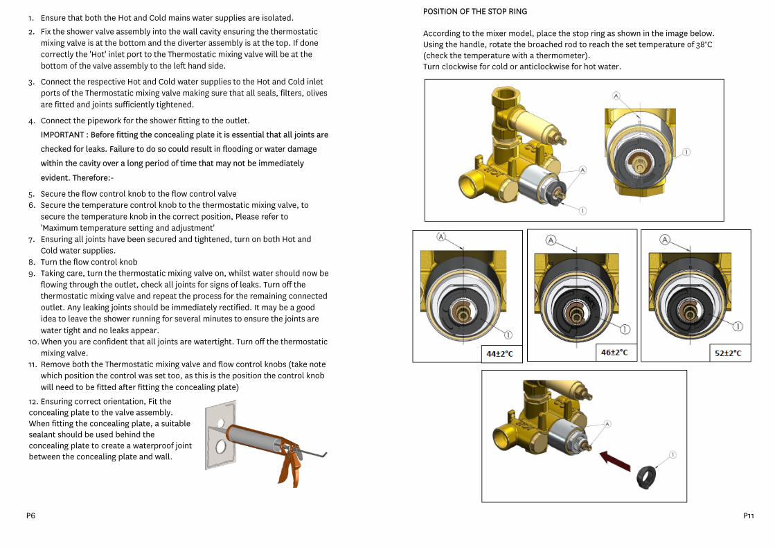
POSITION OF THE STOP RING
According to the mixer model, place the stop ring as shown in the image below. Using the handle, rotate the broached rod to reach the set temperature of 38°C(check the temperature with a thermometer).Turn clockwise for cold or anticlockwise for hot water.
P6 P11
13. Fix the concealing plate on the chromed ring and on thethreaded rod.
14. Screw the adapter (2), or the adapters,with their O-ring (1),until the plate isagainst the wall.
15. Refit and secure the diverter control knob and temperature knob to theposition it was removed in point 11
Maximum Temperature Setting, Adjustment and Valve Commissioning
Whilst the temperature of your Thermostatic mixing valve has been factory tested and calibrated, you may need to perform a slight initial adjustment to suit your system operating setup. To do so:-
1. Loosely fit the temperature control knob to the Thermostatic mixing valve.Note, whilst fitting the knob, there is a temperature stop pin inside the knobwhich is required to line up with the temperature stop ring.
2. Taking extreme care, slowly turn on the thermostatic mixing valve and gentlyrotate the control knob to the maximum temperature position. Let the showerrun for several minutes to ensure the correct blend of hot and cold water andthe maximum outlet hot water temperature has been achieved.
It is important to note at this stage, very hot water MAY flow through eitheroutlet depending on where the diverter is set too and can cause serious burnsif care is not taken!
3. Take note of the outlet temperature of the shower using a suitable testingequipment.
4. If the maximum temperature requires adjusting, remove the temperaturecontrol knob and adjust the thermostatic mixing valve spindle.
To increase the outlet temperature, slowly turn the spindle anti-clockwise
To decrease the outlet temperature, slowly turn the spindle clockwise
5. When the desired temperature is achieved, refit and secure the thermostaticmixing valve control knob lining up the pin in the knob with the temperaturestop ring
6. Turn off the shower valve.
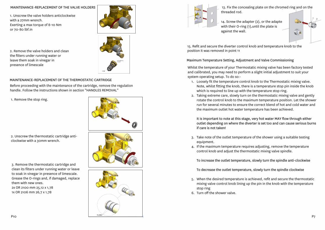
MAINTENANCE-REPLACEMENT OF THE THERMOSTATIC CARTRIDGEBefore proceeding with the maintenance of the cartridge, remove the regulationhandle. Follow the instructions shown in section “HANDLES REMOVAL”
1. Remove the stop ring.
2. Unscrew the thermostatic cartridge anti-clockwise with a 30mm wrench.
3. Remove the thermostatic cartridge andclean its filters under running water or leaveto soak in vinegar in presence of limescale.Grease the O-rings and, if damaged, replacethem with new ones.2x OR 2100 mm 25,12 x 1,781x OR 2106 mm 26,7 x 1,78
MAINTENANCE-REPLACEMENT OF THE VALVE HOLDERS
1. Unscrew the valve holders anticlockwisewith a 27mm wrench.Exerting a max torque of 8-10 Nmor 70-80 lbf.in
2. Remove the valve holders and cleanthe filters under running water orleave them soak in vinegar inpresence of limescale
P10 P7
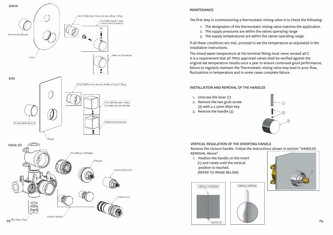
KAHA
Valve 2D
KIRI
1. Unscrew the lever (1)2. Remove the two grub screw
(2) with a 2.5mm Allen Key3. Remove the handle (3)
If all these conditions are met, proceed to set the temperature as stipulated in the installation instructions.
The mixed water temperature at the terminal fitting must never exceed 46°CIt is a requirement that all TMV2 approved valves shall be verified against the original set temperature results once a year to ensure continued good performance, failure to regularly maintain the Thermostatic mixing valve may lead to poor flow, fluctuations in temperature and in some cases complete failure.
INSTALLATION AND REMOVAL OF THE HANDLES
MAINTENANCE
The first step in commissioning a thermostatic mixing valve is to check the following:
1. The designation of the thermostatic mixing valve matches the application2. The supply pressures are within the valves operating range3. The supply temperatures are within the valves operating range.
VERTICAL REGULATION OF THE DIVERTING HANDLERemove the closure handle. Follow the instructions shown in section “HANDLESREMOVAL Above"
1. Position the handle on the insert(1) and rotate until the verticalposition is reached.(REFER TO IMAGE BELOW)
P8 P9