diodes incorporated product design guide s · power management ics dc/dc switching regulators /...
TRANSCRIPT

POWER MANAGEMENT ICS
DC/DC Switching Regulators / Controllers Linear RegulatorsShunt Voltage References Voltage Sup Op Amp / USB Power HALL EFFEDISCRETE SEMICONDUCTORSSchottky / SBR® DiodesSurface Mount Schottky/ SBR® Rectifiers Through-Hole / SBR®
Schottky Rectifiers Switching Diodes Zener Diodes Transient Voltage Suppressors Thyristor Surge Protection (TSPDs)Data Line ProtectionDevices Small Signal / MediumPower Bipolar Transistors Matched Transistor Arrays Darlington Transistors NPN, PNP PrebiasedTransistors MOSFETSComplex Arrays Super-Fast /Ultra-Fast /Fast Recovery Rectifiers Standard Recovery Rectifiers Bridge Rectifiers POWER MANAGEMENT ICS
DC/DC Switching Regulators / Controllers Linear RegulatorsShunt Voltage References Voltage Supervisory Op Amp / Comparators USB Power Switch HALL EFFECT SENSORSDISCRETE SEMICONDUCSchottky / Surface Mou/ SBR® Rectifiers Through-Hole / SBR®
Schottky Rectifiers Switching Diodes
Switching Diodes Zener Diodes Transient Voltage Suppressors (TVSs)Thyristor Surge Protection Devices(TSPDs)Data Line ProtectionDevices Small Signal / Medium
Transistors Matched Transistor Arrays Darlington Transistors NPN, PNP PrebiasedTransistors MOSFETS
Super-Fast /Ultra-Fast /
Standard Recovery
Bridge Rectifiers POWER MANAGEMENT ICS
DC/DC Switching Regulators / Controllers Linear RegulatorsShunt Voltage References Voltage Supervisory Op Amp / Comparators USB Power Switch HALL EFFECT SENSORSDISCRETE
SEMICONDUCTORS
Schottky / SBR® DiodesSurface Mount Schottky/ SBR® Rectifiers Through-Hole / SBR®
Schottky Rectifiers Switching Diodes Zener Diodes Transient Voltage Suppressors (TVSs)Thyristor Surge Protection Devices(TSPDs)Data Line ProtectionDevices Small Signal / MediumPower Bipolar
Darlington Transistors NPN, PNP PrebiasedTransistors MOSFETS
Complex Arrays Super-Fast /Ultra-Fast /Fast Recovery Rectifiers Standard Recovery Rectifiers Bridge Rectifiers POWER MANAGEMENT ICS
DC/DC Switching Regulators / Controllers Linear RegulatorsShunt Voltage References Voltage Supervisory Op Amp / Comparators USB Power Switch HALL EFFECT SENSORSDISCRETE SEMICONDUCTORSSchottky / SBR® DiodesSurface Mount Schottky/ SBR® Rectifiers Through-Hole / SBR®
Schottky Rectifiers Switching Diodes Zener Diodes Transient Voltage Suppressors (TVSs)Thyristor Surge Protection Devices(TSPDs)Data Line ProtectionDevices Small Signal / MediumPower Bipolar Transistors Matched Transistor Arrays Darlington Transistors NPN, PNP PrebiasedTransistors MOSFETSComplex Arrays Super-Fast /Ultra-Fast /Fast Recovery Rectifiers Standard Recovery Rectifiers Bridge Rectifiers POWER MANAGEMENT ICS
DC/DC Switching Regulators / Controllers Linear RegulatorsShunt Voltage References Voltage Supervisory Op Amp / Comparators USB Power Switch HALL EFFECT SENSORSDISCRETE SEMICONDUCTORS
Schottky / SBR® DiodesSurface Mount Schottky/ SBR® Rectifiers Through-Hole / SBR‚Schottky Rectifiers Switching Diodes Zener Diodes Transient Voltage Suppressors (TVSs)Thyristor Surge Protection Devices(TSPDs)Data Line ProtectionDevices Small Signal / MediumPower Bipolar Transistors Matched Transistor Arrays Darlington Transistors NPN, PNP PrebiasedTransistors MOSFETSComplex Arrays Super-Fast /Ultra-Fast /Fast Recovery Rectifiers Standard Recovery Rectifiers Bridge Rectifiers POWER MANAGEMENT ICS
DC/DC Switching Regulators / Controllers Linear RegulatorsShunt Voltage References Voltage Supervisory Op Amp / Comparators USB Power Switch HALL EFFECT SENSORSDISCRETE SEMICONDUCTORSSchottky / SBR® DiodesSurface Mount Schottky/ SBR® Rectifiers Through-Hole / SBR‚Schottky Rectifiers Switching Diodes Zener Diodes Transient Voltage Suppressors (TVSs)Thyristor Surge Protection Devices(TSPDs)Data Line ProtectionDevices Small Signal / MediumPower Bipolar Transistors Matched Transistor
Arrays Darlington Transistors NPN, PNP Prebiased
Transistors MOSFETS
Complex Arrays Super-Fast /Ultra-Fast /Fast Recovery RectifiersStandard Recovery
Rectifiers Bridge Rectifiers POWER MANAGEMENT ICS
DC/DC Switching Regulators / Controllers Linear Regulators
Shunt Voltage References
Voltage Supervisory Op Amp / Comparators USB Power Switch HALL EFFECT SENSORS
DISCRETE SEMICONDUCTORSSchottky / SBR® Diodes Surface Mount Schottky/ SBR‚ Rectifiers Through-Hole / SBR®
Schottky Rectifiers Switching Diodes
Zener Diodes Transient Voltage Suppressors (TVSs)Thyristor Surge Protection Devices
(TSPDs)Data Line Protection
Devices Small Signal / MediumPower Bipolar
Transistors Matched Transistor
Arrays Darlington Transistors NPN, PNP Prebiased
Transistors MOSFETS
Complex Arrays Super-Fast /Ultra-Fast /Fast Recovery RectifiersStandard Recovery
Rectifiers Bridge Rectifiers POWER MANAGEMENT ICS
DC/DC Switching Regulators / ControllersLinear RegulatorsShunt Voltage
References Voltage Supervisory
DIODES INCORPORATED
Product Design Guide
POWER MANAGEMENT ICs
HALL EFFECT SENSORS
DISCRETE SEMICONDUCTORS

Diodes Incorporated’s
Product Design Guide
WWW.DIODES.COM

All data shown in this catalog is subject to change.
For updates, please check the product data sheets on our Corporate website at www.diodes.com
IMPORTANT NOTICE
LIFE SUPPORT
Diodes Incorporated and its subsidiaries reserve the right to make modifications, enhancements, improvements, corrections or other changes without further notice to any product herein. Diodes Incorporated does not assume any liability arising out of the application or use of any product described herein; neither does it convey any license under its patent rights, nor the rights of others. The user of products in such applications shall assume all risks of such use and will agree to hold Diodes Incorporated and all the companies whose products are represented on our website, harmless against all damages.
Diodes Incorporated products are not authorized for use as critical components in life support devices or systems without the expressed written approval of the President of Diodes Incorporated.
PowerDI and SBR are registered trademarks of Diodes Incorporated.
©2007 Diodes Incorporated.
All rights reserved. Printed in the United States of America.

Contents
Contents - 1
About This Product Design Guide ...................................................................1-1 About the Company’s Product Offerings ............................................................................................ 1-1 How This Guide Is Organized............................................................................................................. 1-1 Our Corporate Website....................................................................................................................... 1-2 Lead-Free and “Green” Products ....................................................................................................... 1-2 Technical Support ............................................................................................................................... 1-3 Product Ordering / Sampling .............................................................................................................. 1-3
Power Management ICs DC/DC Switching Regulators & Controllers .......................................................................2-1
Buck Converter – Internal Switch ....................................................................................................... 2-1 Boost Converter – Internal Switch ...................................................................................................... 2-1 Multiple Topology (Buck, Boost, Inverting) Converter – Internal Switch ............................................ 2-2 Buck Controllers – External Switch..................................................................................................... 2-2 Boost Controllers – External Switch ................................................................................................... 2-2 Inductorless Boost Converter – Charge Pump................................................................................... 2-2 Multiple Topology (Buck, Boost, Inverting) Controllers – External Switch ......................................... 2-2
Linear Regulators .................................................................................................................3-1 LDO – Single Output........................................................................................................................... 3-1 Quasi LDO – Single Output ................................................................................................................ 3-2 Quasi LDO – Dual Output................................................................................................................... 3-2 High Efficiency Quasi-LDO – Single Output ....................................................................................... 3-2 General Purpose Linear Regulator..................................................................................................... 3-2
Shunt Voltage References.....................................................................................................4-1 Shunt Voltage References.................................................................................................................. 4-1
Voltage Supervisory ..............................................................................................................5-1 Reset IC (Voltage Supervisor) ............................................................................................................ 5-1
Op Amp / Comparators .........................................................................................................6-1 Operational Amplifiers ........................................................................................................................ 6-1 Comparators ....................................................................................................................................... 6-1
USB Power Switch ................................................................................................................7-1 USB Power Switch.............................................................................................................................. 7-1
Hall Effect Sensors Hall Effect Sensors ...............................................................................................................8-1
Unipolar Switches ............................................................................................................................... 8-1 Bipolar – Latches ................................................................................................................................ 8-1 Bipolar – Latches (Complementary Output) .......................................................................................8-1 Omnipolar – Switches ......................................................................................................................... 8-2 Omnipolar – Switches (Complementary Output) ................................................................................ 8-2 Smart Fan Drivers (Complementary, Latched Output)....................................................................... 8-2
Discrete Semiconductors Schottky / SBR® Diodes ........................................................................................................9-1
Super Barrier Rectifiers (SBR) & Schottky Diodes / DFN1006-2 / DFN1006H4-2............................. 9-1 Super Barrier Rectifiers (SBR) & Schottky Diodes / DFN1616-6 ....................................................... 9-1 Super Barrier Rectifiers (SBR) & Schottky Diodes / SOD-523........................................................... 9-1 Schottky Diodes / SOT-523 ................................................................................................................ 9-1 Schottky Diodes / SOT-563 ................................................................................................................ 9-1 Schottky Diodes / PowerDI®323 ......................................................................................................... 9-2 Schottky Diodes / SOD-323................................................................................................................ 9-2 Schottky Diodes / SOT-323 ................................................................................................................ 9-2 Schottky Diodes / SOT-363 ................................................................................................................ 9-2 Schottky Diodes / SOD-123................................................................................................................ 9-3 Schottky Diodes / SOT-23 .................................................................................................................. 9-3 Schottky Diodes / SC-59..................................................................................................................... 9-4 Schottky Diodes / SOT-26 .................................................................................................................. 9-4

Contents - 2
Surface Mount Schottky / SBR® Rectifiers ..........................................................................10-1 0.5A Super Barrier Rectifiers (SBR) / DFN1006-2 ............................................................................. 10-1 0.5A Schottky Rectifiers / SOD-323.................................................................................................... 10-1 0.5A Schottky Rectifiers / SOT-23...................................................................................................... 10-1 0.5A Schottky Rectifiers / SOD-123.................................................................................................... 10-1 0.75A Schottky Rectifiers / SOT-23.................................................................................................... 10-1 1.0A Schottky Rectifiers / PowerDI®323............................................................................................. 10-1 1.0A Super Barrier Rectifiers (SBR) / Schottky Rectifiers / SOD-323................................................ 10-1 1.0A Schottky Rectifiers / PowerDI®123............................................................................................. 10-1 1.0A Schottky Rectifiers / SOD-123.................................................................................................... 10-2 1.0A Schottky Rectifiers / SOT-23...................................................................................................... 10-2 1.0A Schottky Rectifiers / SMA........................................................................................................... 10-2 1.0A Schottky Rectifiers / SMB........................................................................................................... 10-2 2.0A Super Barrier Rectifiers (SBR) / Schottky Rectifiers / PowerDI®123 ......................................... 10-2 2.0A Super Barrier Rectifiers (SBR) / Schottky Rectifiers / SMA ....................................................... 10-3 2.0A Schottky Rectifiers / SMB........................................................................................................... 10-3 3.0A Super Barrier Rectifiers (SBR) / PowerDI®123 .......................................................................... 10-3 3.0A Super Barrier Rectifiers (SBR) / Schottky Rectifiers / DFN3030-8 ............................................ 10-3 3.0A Schottky Rectifiers / PowerDI®5................................................................................................. 10-3 3.0A Super Barrier Rectifiers (SBR) / Schottky Rectifiers / SMA ....................................................... 10-3 3.0A Schottky Rectifiers / SMB........................................................................................................... 10-4 3.0A Schottky Rectifiers / SMC........................................................................................................... 10-4 4.0A Schottky Rectifiers / PowerDI®5................................................................................................. 10-4 5.0A Schottky Rectifiers / PowerDI®5................................................................................................. 10-4 5.0A Schottky Rectifiers / SMC........................................................................................................... 10-4 7.0A Schottky Rectifiers / PowerDI®5................................................................................................. 10-4 8.0A Schottky Rectifiers / PowerDI®5................................................................................................. 10-4 10.0A Schottky Rectifiers / PowerDI®5............................................................................................... 10-4 10.0A Schottky Rectifiers (Single) / D2PAK........................................................................................ 10-5 10.0A Super Barrier Rectifiers (SBR) / Schottky Rectifiers (Dual) / D2PAK....................................... 10-5 15.0A Schottky Rectifiers (Dual) / D2PAK........................................................................................... 10-5 16.0A Schottky Rectifiers (Dual) / D2PAK........................................................................................... 10-5 20.0A Super Barrier Rectifiers (SBR) / Schottky Rectifiers (Dual) / D2PAK....................................... 10-5 30.0A Schottky Rectifiers (Dual) / D2PAK........................................................................................... 10-5
Through-Hole Schottky / SBR® Rectifiers ...........................................................................11-1 1.0A Schottky Rectifiers / DO-41 ........................................................................................................ 11-1 3.0A Schottky Rectifiers / DO-201AD................................................................................................. 11-1 5.0A Schottky Rectifiers / DO-201AD................................................................................................. 11-1 5.0A Schottky Rectifiers / TO-220AC ................................................................................................. 11-1 7.5A Schottky Rectifiers / TO-220AC ................................................................................................. 11-2 8.0A Schottky Rectifiers / DO-201AD................................................................................................. 11-2 8.0A Schottky Rectifiers / TO-220AC ................................................................................................. 11-2 9.0A Schottky Rectifiers / DO-201AD................................................................................................. 11-2 10.0A Schottky Rectifiers / TO-220AC ............................................................................................... 11-2 10.0A Super Barrier Rectifiers (SBR) / Schottky Rectifiers (Dual) / TO-220AB................................. 11-3 10.0A Super Barrier Rectifiers (SBR) (Dual) / ITO-220AB................................................................. 11-3 15.0A Schottky Rectifiers (Dual) / TO-220AB..................................................................................... 11-3 16.0A Schottky Rectifiers / TO-220AC ............................................................................................... 11-4 16.0A Schottky Rectifiers (Dual) / TO-220AB..................................................................................... 11-4 16.0A Schottky Rectifiers (Dual) / TO-3P ........................................................................................... 11-4 20.0A Super Barrier Rectifiers (SBR) & Schottky Rectifiers (Dual) / TO-220AB ............................... 11-4 20.0A Super Barrier Rectifiers (SBR) (Dual) / ITO-220AB................................................................. 11-5 20.0A Schottky Rectifiers (Dual) / TO-3P ........................................................................................... 11-5 30.0A Super Barrier Rectifiers (SBR) (Dual) / TO-220AB.................................................................. 11-6 30.0A Super Barrier Rectifiers (SBR) (Dual) / ITO-220AB................................................................. 11-6 30.0A Schottky Rectifiers (Dual) / TO-3P ........................................................................................... 11-6 40.0A Super Barrier Rectifiers (SBR) (Dual) / TO-220AB.................................................................. 11-7 40.0A Super Barrier Rectifiers (SBR) (Dual) / ITO-220AB................................................................. 11-7 40.0A Schottky Rectifiers (Dual) / TO-3P ........................................................................................... 11-7 60.0A Super Barrier Rectifiers (SBR) (Dual) / TO-220AB.................................................................. 11-7 60.0A Schottky Rectifiers (Dual) / TO-3P ........................................................................................... 11-8

Contents - 3
Switching Diodes...................................................................................................................12-1 Switching Diodes / DFN1006-2........................................................................................................... 12-1 Switching Diodes / SOD-523 .............................................................................................................. 12-1 Switching Diodes / SOT-523............................................................................................................... 12-1 Low Leakage Signal Diodes / SOT-523 ............................................................................................. 12-1 Switching Diodes / SOT-563............................................................................................................... 12-1 Low Leakage Signal Diodes / SOT-563 ............................................................................................. 12-1 Switching Diodes / PowerDI®323........................................................................................................ 12-1 Switching Diodes / SOD-323 .............................................................................................................. 12-1 Switching Diodes / SOT-323............................................................................................................... 12-2 Low Leakage Signal Diodes / SOT-323 ............................................................................................. 12-2 Switching Diodes / SOT-353............................................................................................................... 12-2 Switching Diodes / SOT-363............................................................................................................... 12-2 Low Leakage Signal Diodes / SOT-363 ............................................................................................. 12-2 Switching Diodes / SOD-123 .............................................................................................................. 12-3 Low Leakage Signal Diodes / SOD-123 ............................................................................................. 12-3 Switching Diodes / SOT-23................................................................................................................. 12-3 Low Leakage Signal Diodes / SOT-23 ............................................................................................... 12-3 Switching Diodes / SOT-26................................................................................................................. 12-3
Zener Diodes .........................................................................................................................13-1 250mW Zener Diodes (Single) / DFN1006-2...................................................................................... 13-1 150mW Zener Diodes (Single) / SOD-523 ......................................................................................... 13-1 150mW Low Test Current Zener Diodes (Single) / SOD-523 ............................................................ 13-2 150mW Zener Diodes (Single) / SOT-523..........................................................................................13-2 150mW Zener Diodes (Quad, Common Anode) / SOT-563 .............................................................. 13-4 200mW Zener Diodes (Single) / SOD-323 ......................................................................................... 13-4 200mW Low Test Current Zener Diodes (Single) / SOD-323 ............................................................ 13-5 200mW Tight Breakdown Tolerance Zener Diodes (Single) / SOD-323............................................ 13-6 500mW Zener Diodes (Single) / PowerDI®323 .................................................................................. 13-6 200mW Zener Diodes (Single) / SOT-323..........................................................................................13-7 200mW Zener Diodes (Dual, Common Anode) / SOT-323................................................................ 13-8 200mW Zener Diodes (Dual, Isolated) / SOT-363 ............................................................................. 13-8 200mW Zener Diodes (Triple, Isolated) / SOT-363............................................................................ 13-10 200mW Low Test Current Zener Diodes (Triple, Isolated) / SOT-363............................................... 13-11 200mW Tight Breakdown Tolerance Zener Diodes (Triple, Isolated) / SOT-363 .......................... 13-12 200mW Zener Diodes (Triple, Bidirectional) / SOT-363..................................................................... 13-12 200mW Zener Diodes (Quad, Common Anode) / SOT-363 .............................................................. 13-12 350mW Zener Diodes (Single) / SOT-23............................................................................................ 13-12 300mW Tight Breakdown Tolerance Zener Diodes (Single) / SOT-23 .............................................. 13-14 300mW Zener Diodes (Dual, Common Anode) / SOT-23.................................................................. 13-14 300mW Zener Diodes (Dual, Common Cathode) / SOT-23............................................................... 13-15 500mW Zener Diodes (Single) / SOD-123 ......................................................................................... 13-16 410mW Zener Diodes (Single) / SOD-123 ......................................................................................... 13-17 500mW Low Test Current Zener Diodes (Single) / SOD-123 ............................................................ 13-17 500mW Tight Breakdown Tolerance Zener Diodes (Single) / SOD-123............................................ 13-18 1W Zener Diodes (Single) / PowerDI®123 ......................................................................................... 13-19 1W Zener Diodes (Single) / SMA........................................................................................................ 13-19
Transient Voltage Suppressors (TVS)..................................................................................14-1 Transient Voltage Suppressors / DFN1006-2 .................................................................................... 14-1 Transient Voltage Suppressors / SOD-523 ........................................................................................14-1 24W Peak Power Transient Voltage Suppressors (Common Anode) / SOT-23................................ 14-1 40W Peak Power Transient Voltage Suppressors (Common Anode) / SOT-23................................ 14-1 40W Peak Power Transient Voltage Suppressors (Common Cathode) / SOT-23 ............................ 14-1 Low Capacitance Transient Voltage Suppressors (Unidirectional) / SOT-23 .................................... 14-1 Transient Voltage Suppressors (Bidirectional) / SOT-23 ................................................................... 14-1 Low Capacitance Transient Voltage Suppressors (Bidirectional) / SOT-26 ...................................... 14-1 225W Transient Voltage Suppressors / PowerDI®123....................................................................... 14-2 400W Transient Voltage Suppressors / SMA..................................................................................... 14-2 600W Transient Voltage Suppressors / SMB..................................................................................... 14-3 600W Transient Voltage Suppressors / DO-15 .................................................................................. 14-5 1500W Transient Voltage Suppressors / SMC................................................................................... 14-6 1500W Transient Voltage Suppressors / DO-201.............................................................................. 14-7
Contents - 4
3000W Transient Voltage Suppressors / SMC................................................................................... 14-7
Thyristor Surge Protection Devices (TSPDs)........................................................................................14-9 30A Bidirectional Thyristor Surge Protection Devices / SMB............................................................. 14-9 50A Bidirectional Thyristor Surge Protection Devices / SMB............................................................. 14-10 100A Bidirectional Thyristor Surge Protection Devices / SMB........................................................... 14-10
Data Line Protection Devices..............................................................................................................14-12 Rail Clamps / SOT-363....................................................................................................................... 14-12 Unidirectional, Low Capacitance, Single Data Line Protection Devices with Integrated TVS / SOT-23...................................................................................................... 14-12 Bidirectional, Low Capacitance, Single Data Line Protection Devices with Integrated TVS / SOT-26...................................................................................................... 14-12
Small Signal and Medium Power Bipolar Transistors........................................................15-1 NPN Transistors / DFN1006-3............................................................................................................ 15-1 PNP Transistors / DFN1006-3............................................................................................................ 15-1 Dual NPN Transistors / DFN1310H4-6 (0.4mm Profile)..................................................................... 15-1 Complementary NPN/PNP Transistors / DFN1310H4-6 (0.4mm Profile) .......................................... 15-1 NPN Transistors / SOT-523................................................................................................................ 15-1 PNP Transistors / SOT-523................................................................................................................ 15-1 Dual NPN Transistors / SOT-563 ....................................................................................................... 15-1 Dual PNP Transistors / SOT-563 ....................................................................................................... 15-1 Complementary NPN/PNP Transistors / SOT-563............................................................................. 15-1 NPN Transistors / SOT-323................................................................................................................ 15-2 PNP Transistors / SOT-323................................................................................................................ 15-2 Dual NPN Transistors / SOT-363 ....................................................................................................... 15-2 Dual PNP Transistors / SOT-363 ....................................................................................................... 15-3 Complementary NPN/PNP Transistors / SOT-363............................................................................. 15-3 NPN Transistors / SOT-23.................................................................................................................. 15-3 UHF/VHF NPN Transistors / SOT-23................................................................................................. 15-3 PNP Transistors / SOT-23.................................................................................................................. 15-4 Dual NPN Transistors / SOT-26 ......................................................................................................... 15-4 Dual PNP Transistors / SOT-26 ......................................................................................................... 15-4 Complementary NPN/PNP Transistors / SOT-26............................................................................... 15-4 Complex Dual NPN/PNP Transistors / SOT-26 ................................................................................. 15-4 Medium Power NPN Transistors / SOT89-3L .................................................................................... 15-4 Medium Power PNP Transistors / SOT89-3L..................................................................................... 15-5 Medium Power NPN Transistors / SOT-223....................................................................................... 15-5 Medium Power PNP Transistors / SOT-223....................................................................................... 15-5
Matched Pair Bipolar Transistors ......................................................................................................................15-7 NPN Matched Pair Bipolar Transistors / SOT-363............................................................................. 15-7 PNP Matched Pair Bipolar Transistors / SOT-363 ............................................................................. 15-7 NPN Matched Pair Bipolar Transistors / SOT-26............................................................................... 15-7 PNP Matched Pair Bipolar Transistors / SOT-26 ............................................................................... 15-7
Darlington Transistors ........................................................................................................................................15-8 NPN Darlington Transistors / SOT-323 .............................................................................................. 15-8 PNP Darlington Transistors / SOT-323 .............................................................................................. 15-8 NPN Darlington Transistors / SOT-23 ................................................................................................ 15-8 PNP Darlington Transistors / SOT-23 ................................................................................................ 15-8
NPN, PNP Prebiased Transistors.........................................................................................16-1 Single 100mA Prebiased Transistors ................................................................................................. 16-1 Single 500mA Prebiased Transistors ................................................................................................. 16-2 Dual 100mA Prebiased Transistors.................................................................................................... 16-2 Dual 100mA Complementary Prebiased Transistors ......................................................................... 16-3 100mA NPN / 500mA PNP Complementary Prebiased Transistors .................................................. 16-3
MOSFETS.............................................................................................................................17-1 N-Channel MOSFET / DFN1006H4-3 (0.4mm Profile) ...................................................................... 17-1 N-Channel MOSFET / DFN1006-3..................................................................................................... 17-1 Dual N-Channel MOSFET / DFN1310H4-6 (0.4mm Profile).............................................................. 17-1 P-Channel MOSFET / DFN1411-3 ..................................................................................................... 17-1 Complementary (N / P Channel) MOSFET / DFN1612-6................................................................... 17-1 Dual N-Channel MOSFET / SOT-563 ................................................................................................17-1 Single P-Channel MOSFET / SOT-563..............................................................................................17-1 Dual P-Channel MOSFET / SOT-563................................................................................................. 17-1

Contents - 5
Complementary (N / P Channel) MOSFET / SOT-563....................................................................... 17-1 N-Channel MOSFET / SOT-323......................................................................................................... 17-1 P-Channel MOSFET / SOT-323 ......................................................................................................... 17-1 Dual N-Channel MOSFET / SOT-363 ................................................................................................17-2 Complementary (N / P Channel) MOSFET / SOT-363....................................................................... 17-2 Dual P-Channel MOSFET / SOT-363................................................................................................. 17-2 N-Channel MOSFET / SOT-23........................................................................................................... 17-2 P-Channel MOSFET / SOT-23 ........................................................................................................... 17-2 Dual N-Channel MOSFET / SOT-26 .................................................................................................. 17-2 P-Channel MOSFET / SOT-26 ........................................................................................................... 17-2 Dual P-Channel MOSFET / SOT-26................................................................................................... 17-2 N-Channel MOSFET / SC-59 ............................................................................................................. 17-3 P-Channel MOSFET / SC-59.............................................................................................................. 17-3
Complex Arrays.....................................................................................................................18-1 Discrete Load Switches / SOT-363 .................................................................................................... 18-1 Discrete Load Switches / SOT-26....................................................................................................... 18-1 MOSFET and Schottky Arrays / DFN2020B-6 ................................................................................... 18-2 MOSFET and Schottky Arrays / SOT-363.......................................................................................... 18-2 Discrete – Half H-Bridge Motor Driver / SOT-363 .............................................................................. 18-2 Relay Drivers / SOT-363..................................................................................................................... 18-3 Discrete – Voltage Regulators / SOT-363 .......................................................................................... 18-4
Super-Fast /Ultra-Fast / Fast Recovery Rectifiers ..............................................................19-1 1.0A Super-Fast Recovery Glass Passivated Rectifiers / PowerDI®123 ........................................... 19-1 1.0A Super-Fast Recovery Glass Passivated Rectifiers / SMA ......................................................... 19-1 1.0A Super-Fast Recovery Glass Passivated Rectifiers / SMB ......................................................... 19-1 1.0A Super-Fast Recovery Glass Passivated Rectifiers / DO-41 ...................................................... 19-1 1.0A Ultra-Fast Recovery Glass Passivated Rectifiers / SMA ........................................................... 19-1 1.0A Ultra-Fast Recovery Rectifiers / DO-41...................................................................................... 19-1 1.0A Ultra-Fast Recovery Glass Passivated Rectifiers / DO-41 ........................................................ 19-2 1.0A Fast Recovery Glass Passivated Rectifiers / SMA .................................................................... 19-2 1.0A Fast Recovery Glass Passivated Rectifiers / SMB .................................................................... 19-2 1.0A Fast Recovery Rectifiers / A-405................................................................................................ 19-2 1.0A Fast Recovery Glass Passivated Rectifiers / A-405 .................................................................. 19-3 1.0A Fast Recovery Rectifiers / DO-41 .............................................................................................. 19-3 1.0A Fast Recovery Glass Passivated Rectifiers / DO-41 ................................................................. 19-3 1.5A Ultra-Fast Recovery Rectifiers / DO-41...................................................................................... 19-3 1.5A Ultra-Fast Recovery Rectifiers / DO-15...................................................................................... 19-4 1.5A Fast Recovery Glass Passivated Rectifiers / SMA .................................................................... 19-4 1.5A Fast Recovery Glass Passivated Rectifiers / SMB .................................................................... 19-4 1.5A Fast Recovery Rectifiers / DO-41 .............................................................................................. 19-4 1.5A Fast Recovery Glass Passivated Rectifiers / DO-41 ................................................................. 19-4 1.5A Fast Recovery Rectifiers / DO-15 .............................................................................................. 19-4 1.5A Fast Recovery Glass Passivated Rectifiers / DO-15 ................................................................. 19-5 2.0A Super-Fast Recovery Glass Passivated Rectifiers / SMA ......................................................... 19-5 2.0A Super-Fast Recovery Glass Passivated Rectifiers / SMB ......................................................... 19-5 2.0A Super-Fast Recovery Glass Passivated Rectifiers / DO-15 ...................................................... 19-5 2.0A Ultra-Fast Recovery Rectifiers / DO-15...................................................................................... 19-5 2.0A Ultra-Fast Recovery Glass Passivated Rectifiers / DO-15 ........................................................ 19-5 2.0A Fast Recovery Rectifiers / DO-15 .............................................................................................. 19-6 2.0A Fast Recovery Glass Passivated Rectifiers / DO-15 ................................................................. 19-6 3.0A Ultra-Fast Recovery Glass Passivated Rectifiers / PowerDI®5 ................................................. 19-6 3.0A Super-Fast Recovery Glass Passivated Rectifiers / SMB ......................................................... 19-6 3.0A Super-Fast Recovery Glass Passivated Rectifiers / SMC ......................................................... 19-6 3.0A Super-Fast Recovery Glass Passivated Rectifiers / DO-201AD ............................................... 19-6 3.0A Ultra-Fast Recovery Rectifiers / DO-201AD .............................................................................. 19-7 3.0A Ultra-Fast Recovery Glass Passivated Rectifiers / DO-201AD ................................................. 19-7 3.0A Fast Recovery Glass Passivated Rectifiers / SMB .................................................................... 19-7 3.0A Fast Recovery Glass Passivated Rectifiers / SMC 19-7 3.0A Fast Recovery Rectifiers / DO-201AD ....................................................................................... 19-7 3.0A Fast Recovery Glass Passivated Rectifiers / DO-201AD .......................................................... 19-7 4.0A Ultra-Fast Recovery Glass Passivated Rectifiers / PowerDI®5 ................................................. 19-8 5.0A Ultra-Fast Recovery Glass Passivated Rectifiers / PowerDI®5 ................................................. 19-8

Contents - 6
6.0A Ultra-Fast Recovery Glass Passivated Rectifiers / PowerDI®5 ................................................. 19-8 6.0A Ultra-Fast Recovery Glass Passivated Rectifiers (Dual) / PowerDI®5 ...................................... 19-8 6.0A Fast Recovery Glass Passivated Rectifiers / R-6 ...................................................................... 19-8 16.0A Super-Fast Recovery Glass Passivated Rectifiers (Dual) / D2PAK......................................... 19-8
Standard Recovery Rectifiers................................................................................................20-1 1.0A Standard Recovery Glass Passivated Rectifiers / PowerDI®123 .............................................. 20-1 1.0A Standard Recovery Glass Passivated Rectifiers / SMA ............................................................ 20-1 1.0A Standard Recovery Glass Passivated Rectifiers / SMB ............................................................ 20-1 1.0A Standard Recovery Rectifiers / A-405........................................................................................ 20-1 1.0A Standard Recovery Glass Passivated Rectifiers / A-405........................................................... 20-1 1.0A Standard Recovery Rectifiers / DO-41....................................................................................... 20-2 1.0A Standard Recovery Glass Passivated Rectifiers / DO-41.......................................................... 20-2 1.0A Standard Recovery Glass Passivated Rectifiers / T-1............................................................... 20-2 1.5A Standard Recovery Glass Passivated Rectifiers / SMA ............................................................ 20-2 1.5A Standard Recovery Glass Passivated Rectifiers / SMB ............................................................ 20-2 1.5A Standard Recovery Rectifiers / DO-41....................................................................................... 20-3 1.5A Standard Recovery Rectifiers / DO-15....................................................................................... 20-3 1.5A Standard Recovery Glass Passivated Rectifiers / DO-15.......................................................... 20-3 2.0A Standard Recovery Rectifiers / DO-15....................................................................................... 20-3 2.0A Standard Recovery Glass Passivated Rectifiers / DO-15.......................................................... 20-3 3.0A Standard Recovery Glass Passivated Rectifiers / PowerDI®5 .................................................. 20-4 3.0A Standard Recovery Glass Passivated Rectifiers / SMB ............................................................ 20-4 3.0A Standard Recovery Glass Passivated Rectifiers / SMC ............................................................ 20-4 3.0A Standard Recovery Rectifiers / DO-201AD................................................................................ 20-4 3.0A Standard Recovery Glass Passivated Rectifiers / DO-201AD................................................... 20-4 5.0A Standard Recovery Glass Passivated Rectifiers / PowerDI®5 .................................................. 20-4 5.0A Standard Recovery Glass Passivated Rectifiers / SMC ............................................................ 20-5 6.0A Standard Recovery Rectifiers / R-6............................................................................................ 20-5 8.0A Standard Recovery Glass Passivated Rectifiers / SMC ............................................................ 20-5 10.0A Standard Recovery Rectifiers / R-6.......................................................................................... 20-5
Bridge Rectifiers....................................................................................................................21-1 0.225A Switching Diode Arrays / SOT-26 .......................................................................................... 21-1 0.35A Schottky Barrier Diode Arrays / SOT-26 .................................................................................. 21-1 0.5A Fast Recovery Glass Passivated Bridge Rectifiers / MiniDIP.................................................... 21-1 0.8A Glass Passivated Bridge Rectifiers / MiniDIP ............................................................................ 21-1 1.0A Glass Passivated Bridge Rectifiers / DF-S ................................................................................ 21-1 1.0A Glass Passivated Bridge Rectifiers / DF-M................................................................................ 21-1 1.5A Glass Passivated Bridge Rectifiers / DF-S ................................................................................ 21-1 1.5A Glass Passivated Bridge Rectifiers / DF-M................................................................................ 21-2 1.5A Glass Passivated Bridge Rectifiers / WOG................................................................................ 21-2 1.5A Glass Passivated Bridge Rectifiers / KBP.................................................................................. 21-2 2.0A Glass Passivated Bridge Rectifiers / WOG................................................................................ 21-2 2.0A Glass Passivated Bridge Rectifiers / KBP.................................................................................. 21-2 4.0A Glass Passivated Bridge Rectifiers / GBU................................................................................. 21-3 4.0A Glass Passivated Bridge Rectifiers / KBJ .................................................................................. 21-3 6.0A Glass Passivated Bridge Rectifiers / GBJ.................................................................................. 21-3 6.0A Glass Passivated Bridge Rectifiers / GBU................................................................................. 21-3 6.0A Glass Passivated Bridge Rectifiers / KBJ .................................................................................. 21-4 8.0A Glass Passivated Bridge Rectifiers / GBJ.................................................................................. 21-4 8.0A Glass Passivated Bridge Rectifiers / GBU................................................................................. 21-4 10.0A Glass Passivated Bridge Rectifiers / GBJ................................................................................ 21-4 10.0A Glass Passivated Bridge Rectifiers / GBU............................................................................... 21-4 15.0A Glass Passivated Bridge Rectifiers / GBJ................................................................................ 21-5 15.0A Glass Passivated Bridge Rectifiers / GBPC............................................................................. 21-5 15.0A Glass Passivated Bridge Rectifiers / GBPC-W........................................................................ 21-5 20.0A Glass Passivated Bridge Rectifiers / GBJ................................................................................ 21-5 25.0A Glass Passivated Bridge Rectifiers / GBJ................................................................................ 21-5 25.0A Glass Passivated Bridge Rectifiers / GBPC............................................................................. 21-6 25.0A Glass Passivated Bridge Rectifiers / GBPC-W........................................................................ 21-6 35.0A Glass Passivated Bridge Rectifiers / GBPC............................................................................. 21-6 35.0A Glass Passivated Bridge Rectifiers / GBPC-W........................................................................ 21-6
Appendix: Product Packaging Information ............................................................................... Appendix
Alphanumeric Part Number Index ................................................................................................... Index-1

About This Product Design Guide 1-1
About This Product Design Guide
About the Company’s Product Offerings
Diodes Incorporated is a leading global manufacturer and supplier of high-quality, application-specific standard products within the broad discrete and analog semiconductor markets, serving the consumer electronics, computing, communications, industrial and automotive markets.
How This Guide Is Organized
This Product Design Guide provides an overview of Diodes, Inc.’s product portfolio. It is arranged into the following three product categories:
Power Management ICs Hall Effect Sensors Discrete Semiconductors
The first two sections present our new Analog IC product portfolio. The third section contains our Discrete components, including our new high-performance Super Barrier Rectifiers, or SBR® devices. Under these broad categories, the parts are arranged from low to high power/current and small to large packages.
In this Guide, basic electrical and mechanical parameters of our Analog and Discrete products are provided to support your selection of the proper components for your applications.
The Analog Power Management ICs and Hall Effect Sensors include:
Power Management ICs: DC/DC Switching Regulators and Controllers; Linear Regulators; Shunt Voltage References; Voltage Supervisory; Op Amp / Comparators and USB Power Switches.
Hall Effect Sensors: Unipolar and Omnipolar Switches, Bipolar Latches and Smart Fan Drivers.
The Discrete Semiconductors section includes:
Schottky / SBR® Diodes; Switching and Zener Diodes
Surface Mount Schottky / SBR® Rectifiers
Through-Hole Schottky / SBR® Rectifiers
Transient Voltage Suppressor (TVS), Thyristor Surge Protection Devices (TSPD) and Data Line Protection Devices
Small Signal and Medium Power Bipolar Transistors, Matched Transistor Arrays, and Darlington Transistors
NPN, PNP Prebiased Transistors
MOSFETS
Complex Arrays
Super-Fast / Ultra-Fast / Fast / Standard Recovery and Bridge Rectifiers

About This Product Design Guide 1-2
For package outline drawings and suggested pad layouts, turn to the Appendix. To locate part numbers, turn to the Alphanumeric Part Number Index at the back. Our Corporate Website For up-to-date product information, please refer to our Corporate website at www.diodes.com. This site is available in English, Chinese, and Korean. On our website, you will find:
Current product specifications / data sheets
Product (Parametric) Catalog – Advanced Search
Lead Free / PB-Free / RoHS compliance information
“Contact Us” – for specific Technical and Sales information
Global Sales Contact information – with Regional Sales Office Locations
Online Cross References, SPICE Models, Material Content Reports, and much more. Lead Free and “Green” Products The Company-wide policy is to offer all of our products in Lead Free or Lead Free Finish, RoHS Compliant format. In addition, we have introduced many of our product packages in “Green”* format, no Halogens or Antimony compounds. In 2008-9, we will continue to release more products in the RoHS Lead Free and Green format.
Currently, Lead Free/Lead Free Finish, RoHS Compliant products are considered the Company’s standard products.
Lead Free products are clearly identified. Until lead-containing parts are discontinued, Diodes, Inc. will use the “-F” suffix on part numbers for products that are Lead Free or have a Lead-Free finish.
Please go to www.diodes.com for the current Lead Free and “Green” status of any part, as indicated on our latest data sheets, as follows:
1. Lead Free finish RoHS Compliant shown as “Lead Free Finish, RoHS Compliant”
2. Pb-Free
Lead-free
3. Pb-Free Green
Lead-free Green
Some SnPb finished, RoHS 5/6 Compliant products may remain available. Use of “-F” Suffix generally indicates that an SnPb version previously existed. Contact your Diodes, Inc. Sales Representative for further information. ______________ * Diodes, Inc. defines “Green” as RoHS Compliant as well as Halogen and Antimony free. To determine status, refer to the Company’s product data sheets on our website at www.diodes.com.

About This Product Design Guide 1-3
Technical Support Diodes Incorporated provides compact discrete semiconductor solutions and analog integrated circuits to a wide variety of end markets. Our engineers work closely with our customers to develop application-specific solutions that offer improved performance in optimal package configurations. For technical or sales support, go to www.diodes.com or contact Diodes Incorporated at: The Americas Tel: 805-446-4800 Europe Tel: +33/(0)5.62.30.94.06 Taiwan Tel: +886-2-8914-6000 Shanghai Tel: +86-21-5241-4882 Shenzhen Tel: +86-755-8828-4988 Korea Tel: +82(31) 273-1884 Product Ordering / Sampling To order products or request samples, please contact your local Sales Representative or visit our website at www.diodes.com. A complete list of our Sales Representatives is available on our website.

Part
Num
ber
Min
imum
Inpu
t Vo
ltage
(V)
Max
imum
Inpu
t Vo
ltage
(V)
Out
put V
olta
ge (V
)
Out
put C
urre
nt (A
)
Freq
uenc
y (H
z)
Type
Switc
h To
polo
gy
Out
put C
hann
els
Ope
ratin
g Te
mpe
ratu
reR
ange
(°C
)
Soft
Star
t
Enab
le P
in
Ava
ilabl
e Pa
ckag
es
AP1604A 2.2 5.5 1.2 to 5.5 ADJ 0.8 600K
Fixed PWM / PFM Asynchronous 1 -25 to +80 X X SOT-25
AP1635 2.2 5 2 to Vcc ADJ 1.2 700K Fixed PWM/PFM Asynchronous 1 -25 to +85 X X SOP-8L
AP5001 3.6 20 0.8 to Vcc ADJ 1.5 750K PWM Asynchronous 1 -25 to +85 X X SOP-8L
AP1533 4 23 0.8 to Vcc ADJ 1.8 300K
Fixed PWM Asynchronous 1 -25 to +85 X X SOP-8L
AP1512 4.5 60 3.3/5/12/ 1.23 to 37 2 50K
Fixed PWM Asynchronous 1 -40 to +125 - X TO-263TO-220
AP5002 3.6 22 0.8 to Vcc ADJ 2 500K PWM Asynchronous 1 -25 to +85 X X SOP-8L
AP1520 3.6 23 0.8 to Vcc ADJ 2 300K
Fixed PWM Asynchronous 1 -20 to +85 X X SOP-8L
AP1509 4.5 22 3.3/5/12/ 1.23 to 18 2 150K
Fixed PWM Asynchronous 1 -20 to +125 - X SOP-8L
AP1513 3.6 18 0.8 to Vcc ADJ 2 300K
Fixed PWM Asynchronous 1 -20 to +85 X X SOP-8L
AP5004 10 32 0.8 to0.9 Vcc 2.5 300K
Fixed PWM Asynchronous 1 -25 to +85 - X SOP-8L
AP1512A 4.5 60 3.3/5/12/ 1.23 to 37 3 50K
Fixed PWM Asynchronous 1 -40 to +125 - X TO-263TO-220
AP1580 10 40 0.8 to0.9 Vcc 3 300K
Fixed PWM Asynchronous 1 -25 to +85 - X SOP-8L
AP1501 4.5 40 3.3/5/12/ 1.23 to 37 3 150K
Fixed PWM Asynchronous 1 -20 to +125 - X TO-263TO-220
AP1510 3.6 23 0.8 to Vcc ADJ 3 300K
Fixed PWM Asynchronous 1 -20 to +85 X X SOP-8L
AP1506 4.5 22 3.3/5/12/ 1.23 to 18 3 150K
Fixed PWM Asynchronous 1 -20 to +125 - X TO-263TO-220
AP1507 4.5 22 3.3/5/12/ 1.23 to 18 3 150K
Fixed PWM Asynchronous 1 -20 to +125 - X TO-252
AP1530 3.6 18 0.8 to Vcc ADJ 3 300K
Fixed PWM Asynchronous 1 -20 to +85 X X SOP-8L
AP1501A 4.5 40 3.3/5/12/ 1.23 to 37 5 150K
Fixed PWM Asynchronous 1 -20 to +125 - X TO-263TO-220
AP1511 3.6 23 0.8 to Vcc ADJ 5 300K
Fixed PWM Asynchronous 1 -20 to +85 X X SOP-16L
AP1603 0.9 5.5 3.3 / 5 2 to 5.5 ADJ 0.3 150K
Max. PFM Synchronous 1 -40 to +85 - X SOT-26
AP1601 0.9 5.5 1.8 - 5.5 ADJ 0.42 100K
Max. PFM Synchronous 1 -40 to +85 - X MSOP-8LMSOP-10L
AP1609 2.5 6 3 to 17 ADJ 2.4 300K
Fixed PWM/PFM Asynchronous 1 -20 to +80 X X SOP-8L
All data is subject to change. Please check our data sheets at www.diodes.com for updates. DC/DC Switching Regulators & Controllers 2-1
Boost Converter - Internal Switch
Power Management ICsDC/DC Switching Regulators & Controllers
Buck Converter - Internal Switch

Part
Num
ber
Min
imum
Inpu
t Vo
ltage
(V)
Max
imum
Inpu
t Vo
ltage
(V)
Out
put V
olta
ge
(V)
Out
put C
urre
nt
(A)
Freq
uenc
y (H
z)
Type
Switc
h To
polo
gy
Out
put C
hann
els
Ope
ratin
g Te
mpe
ratu
reR
ange
(°C
)
Soft
Star
t
Enab
le P
in
Ava
ilabl
e Pa
ckag
es
AP34063 3 40 1.25 to Vcc ADJ 1.6 100K
ADJ PWM Asynchronous 1 -20 to +105 - X PDIPSOP-8L
Part
Num
ber
Min
imum
Inpu
t Vo
ltage
(V)
Max
imum
Inpu
t Vo
ltage
(V)
Out
put V
olta
ge
Adj
usta
ble
(V)
Max
imum
D
uty
Cyc
le (%
)
Fre
quen
cy (H
z)
Typ
e
Switc
h To
polo
gy
Out
put
Cha
nnel
s
Ope
ratin
g Te
mpe
ratu
reR
ange
(°C
)
Sof
t Sta
rt
Ena
ble
Pin
Ava
ilabl
e Pa
ckag
es
AP2008 3.6 20 0.77 to 18.5 - 300K ADJ PWM Asynchronous 1 -20 to +85 X - SOP-8L
AP2014 AP2014A
4.5 20 1.25 to 20 95200K 400K Fixed
PWM Synchronous 1 0 to +125 X - SOP-8L
AP2004 3.6 27 1.25 to 25 - 300K ADJ PWM Asynchronous 1 -20 to +85 X - SOP-8L
AP1624 0.9 6 2.5 to 15 80/35 300K Fixed PWM / PFM Asynchronous 1 -30 to +80 - X SOT-25
Part
Num
ber
Min
imum
Inpu
t Vo
ltage
(V)
Max
imum
Inpu
t Vo
ltage
(V)
Max
imum
Out
put
Cur
rent
(mA
)
Prog
ram
mab
le
Freq
uenc
y (H
z)
Cha
rge
Pum
p M
ode
Stan
dby
Qui
esce
nt
Cur
rent
(µ
A) t
yp
Dim
min
g C
ontr
ol
Out
put
Cha
nnel
s
Ope
ratin
g Te
mpe
ratu
reR
ange
(°C
)
Sof
t Sta
rt
1-W
ire S
eria
l D
igita
l Int
erfa
ce
Ava
ilabl
e Pa
ckag
es
AP3152 2.7 5.5 30 /1-Ch120 /4-Ch
1.2M/0.6M/1.8M
1x, 1.5x,
2x1 16-step
Logarithmic Scale 4 -40 to +85 X X DFN3030-12
Part
Num
ber
Min
imum
Inpu
t Vo
ltage
(V)
Max
imum
Inpu
t Vo
ltage
(V)
Out
put V
olta
ge
Adj
usta
ble
(V)
Out
put V
olta
ge
Acc
urac
y (%
)
Fre
quen
cy (H
z)
Typ
e
Switc
h To
polo
gy
Out
put
Cha
nnel
s
Ope
ratin
g Te
mpe
ratu
reR
ange
(°C
)
Sof
t Sta
rt
Ena
ble
Pin
Ava
ilabl
e Pa
ckag
es
AP2001 3.6 40 2.5 to 40 1 500K ADJ PWM Asynchronous 2 -20 to +85 - - SOP-16L
DC/DC Switching Regulators & Controllers 2-2 All data is subject to change. Please check our data sheets at www.diodes.com for updates.
Multiple Topology (Buck, Boost, Inverting) Controllers - External Switch
Inductorless Boost Converter - Charge Pump
Boost Controllers - External Switch
Power Management ICs
Buck Controllers - External Switch
Multiple Topology (Buck, Boost, Inverting) Converter - Internal Switch
DC/DC Switching Regulators & Controllers

Par
t Num
ber
Out
put C
urre
nt (A
)
Max
imum
D
ropo
ut V
olta
ge (V
)
Qui
esce
nt C
urre
nt
(µA
) Typ
PSR
R (d
B)
Max
imum
Ope
ratin
g In
put
Volta
ge (V
)
Out
put V
olta
ge (V
)
Ope
ratin
g Te
mpe
ratu
re R
ange
(°
C)
Feat
ures
Ava
ilabl
e Pa
ckag
es
AP7115 0.15 0.35 50 68 at 1kHz 5.51.0/1.2/1.5/1.8/2.5/2.8/
2.85/3.0/3.3/3.5-40 to +85
Thermal Shutdown Protection,
Enable
SOT-25SOT-353
AP133 0.3 0.45 40 65 at 1kHz 6 ADJ1V to 5V -40 to +85
Thermal Shutdown Protection,
Enable
SOT-25 DFN2020-6
AP139 0.3 0.45 45 60 at 1kHz 5.51.5/1.8/2.0/2.5/2.8/3.0/
3.3/3.5-40 to +125
Thermal Shutdown Protection,
Enable
SOT-25
AP130 0.3 0.5 50 58 at 100Hz 5.5
1.5/1.8/2.0/2.5/2.8/3.0/3.3/ 3.5
-40 to +125Thermal
Shutdown Protection
SOT-23SC59-3L/R SOT-89/R
AP131 0.3 0.5 50 60 at 100Hz 5.5
1.5/1.8/2.0/2.5/2.8/3.0/3.3/ 3.5
-40 to +125Thermal
Shutdown Protection
SOT-25
AP7217 0.5 0.25 35 55 at 1KHz 5.5 3.3 -40 to +85 Enable, Reset Output SOP-8L
AP7165 0.6 0.4 125 60 at 1KHz 5.5 ADJ0.8V to 5V -40 to +85
Thermal Shutdown Protection,
Enable, Power-OK output
SOP-8L DFN3030-10
AP7167 1.2 0.8 125 60 at 1KHz 5.5 ADJ0.8V to 5V -40 to +85
Thermal Shutdown Protection,
Enable, Power-OK Output
SOP-8L DFN3030-10
All data is subject to change. Please check our data sheets at www.diodes.com for updates. Linear Regulators 3-1
Linear RegulatorsPower Management ICs
LDO - Single Output

Par
t Num
ber
Out
put C
urre
nt (A
)
Max
imum
D
ropo
ut V
olta
ge (V
)
Max
imum
Ope
ratin
g In
put
Volta
ge (V
)
Out
put V
olta
ge (V
)
Out
put A
cura
cy (%
)
Ope
ratin
g Te
mpe
ratu
re R
ange
(°
C)
Feat
ures
AP1115A/B 0.6 1.3 181.5 / 1.8 / 2.5 /2.8/3.0/ 3.3 / 3.5 / 5.0 / ADJ
2 0 to +150Thermal
Shutdown Protection
APX1117 1 1.3 18 1.8 / 2.5 / 3.3 / ADJ 2 0 to +125
Thermal Shutdown Protection
AP1117 1 1.4 18 1.5 / 1.8 / 2.5 / 3.3 / 5.0 / ADJ 2 0 to +125
Thermal Shutdown Protection
AP1122 1 1.4 12 1.2 2 0 to +125Thermal
Shutdown Protection
AP1086 1.5 1.4 12 1.5 / 1.8 / 2.5 / 3.3 / 5.0 / ADJ 2 0 to +150
Thermal Shutdown Protection
AP1084 5 1.4 12 1.5 / 1.8 / 2.5 / 3.3 / 5.0 / ADJ 2 0 to +125
Thermal Shutdown Protection
AP1120 / AP1121A 1 1.4 18 ch1:3.3 ch2: 2.5 2 0 to +150
Thermal Shutdown Protection
AP1120B / AP1121B 1 1.4 18 ch1:3.3 ch2: 1.8 2 0 to +150
Thermal Shutdown Protection
AP1186 1.5 0.38 16 1.5 / 1.8 / 2.5 / 3.3 / 5.0 / ADJ 2 0 to +150
Thermal Shutdown Protection
AP1184 4 0.85 16 1.5 / 1.8 / 2.5 / 3.3 / 5.0 / ADJ 2 0 to +125
Thermal Shutdown Protection
AP78L05 0.1 1.9 30 5.0 4 -20 to +125Thermal
Shutdown Protection
AP78L08 0.1 1.9 30 8.0 4 -20 to +125Thermal
Shutdown Protection
AP78L12 0.1 1.9 30 12 4 -20 to +125Thermal
Shutdown Protection
Linear Regulators 3-2 All data is subject to change. Please check our data sheets at www.diodes.com for updates.
TO263-3LTO252-3L TO220-3L
SOP-8L
SOT223-3LTO252-3L
SOT223-3LTO252-3LTO220-3LSOT89-3L TO263-3L
SOT223-3LTO252-3L SOT89-3LTO263-3LTO252-3L TO220-3L
SOP-8L
TO263-5LTO220-5L
Power Management ICsLinear Regulators
Ava
ilabl
e Pa
ckag
es
Quasi LDO - Single Output
Quasi LDO - Dual Output
High Efficiency Quasi-LDO - Single Output
SOT89-3L
TO263-5LTO220-5L
TO92-3LSOP-8L
TO92-3LSOP-8L
TO92-3LSOP-8L
General Purpose Linear Regulator
Par
t Num
ber
Ref
eren
ce V
olta
ge
(V)
Acc
urac
y (%
)
Max
imum
Inpu
t Vo
ltage
(V)
Sin
k C
urre
nt (m
A)
Min
imum
Cat
hode
C
urre
nt fo
r R
egul
atio
n (m
A)
(Typ
.)
Typ
ical
Tem
pera
ture
C
oeffi
cien
t (pp
m/°C
)
Ope
ratin
g Te
mpe
ratu
re R
ange
(°
C)
Ava
ilabl
e Pa
ckag
es
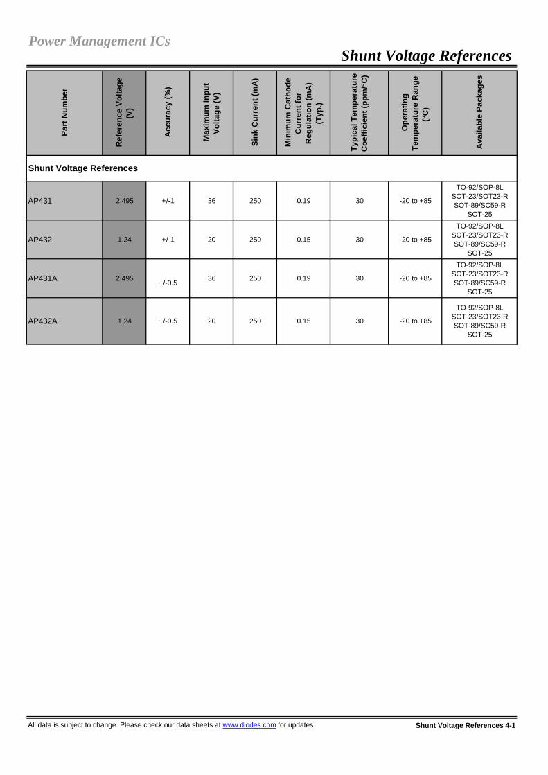
AP431 2.495 +/-1 36 250 0.19 30 -20 to +85
TO-92/SOP-8LSOT-23/SOT23-RSOT-89/SC59-R
SOT-25
AP432 1.24 +/-1 20 250 0.15 30 -20 to +85
TO-92/SOP-8LSOT-23/SOT23-RSOT-89/SC59-R
SOT-25
AP431A 2.495 +/-0.5 36 250 0.19 30 -20 to +85
TO-92/SOP-8LSOT-23/SOT23-RSOT-89/SC59-R
SOT-25
AP432A 1.24 +/-0.5 20 250 0.15 30 -20 to +85
TO-92/SOP-8LSOT-23/SOT23-RSOT-89/SC59-R
SOT-25
All data is subject to change. Please check our data sheets at www.diodes.com for updates. Shunt Voltage References 4-1
Shunt Voltage ReferencesPower Management ICs
Shunt Voltage References

Par
t Num
ber
Det
ect V
olta
ges
(V)
Ope
ratin
g Vo
ltage
R
ange
(V)
Qui
esce
nt C
urre
nt
(µA
)
Res
et T
hres
hold
A
ccur
acy
(%)
Typi
cal T
ime
Del
ay
(ms)
Res
et O
utpu
t To
polo
gy
Res
et O
utpu
t Po
larit
y
Ope
ratin
g Te
mpe
ratu
re R
ange
(°
C)
Ava
ilabl
e Pa
ckag
es
AP1701/32.25/2.63/2.93/3.08/4.00/4.38/
4.631 to 5.5 20 +/-2.5 240 Push-Pull Active-Low -40 to +105 SC-59
AP1702/42.25/2.63/2.93/3.08/4.00/4.38/
4.631 to 5.5 20 +/-2.5 240 Push-Pull Active-High -40 to +105 SC-59
All data is subject to change. Please check our data sheets at www.diodes.com for updates. Voltage Supervisory 5-1
Voltage SupervisoryPower Management ICs
Reset IC (Voltage Supervisor)

Part
Num
ber
Rai
l to
Rai
l I/O
Sup
ply
Volta
ge R
ange
(V)
Gai
n B
andw
idth
(typ
) (M
Hz)
CM
RR
(dB
)
Sup
ply
Cur
rent
(mA
) @ 5
V (p
er O
p A
mp)
Inpu
t Offs
et V
olta
ge (t
yp) (
mV)
Inpu
t Bia
s C
urre
nt (n
A)
Inpu
t Com
mon
M
ode
Volta
ge (V
)
Out
put S
win
g @
10K
Ohm
Out
put D
river
(mA
)
Num
ber o
f Cha
nnel
s
Ope
ratin
g Te
mpe
ratu
reR
ange
(°C
)
Ava
ilabl
e Pa
ckag
es
AP358 - 3 to 32 1 85 0.5 2.0 45 0 to V+ -1.5 0 to V+ -1.5V Source: 40Sink: 20 2 0 to +70 SOP-8L
PDIP-8L
APX321Input and
Output2.5 to 5.5 1 65 0.11 1.7 15 V- +0.2 to
V+ -0.2V- +10mV to
V+ -10mVSource: 60
Sink: 90 1 -40 to +85 SOT-25SOT-353
APX358Input and
Output2.5 to 5.5 1 65 0.19 1.7 15 V- +0.2 to
V+ -0.2V- +10mV to
V+ -10mVSource: 60
Sink: 90 2 -40 to +85 MSOP-8LSOP-8L
APX324Input and
Output2.5 to 5.5 1 65 0.34 1.7 15 V- +0.2 to
V+ -0.2V- +10mV to
V+ -10mVSource: 60
Sink: 90 4 -40 to +85 TSSOP-14L
Part
Num
ber
Rai
l to
Rai
l I/O
Sup
ply
Volta
ge R
ange
(V)
Sup
ply
Cur
rent
(mA
) @5V
Inpu
t Offs
et V
olta
ge (t
yp) (
mV)
Inpu
t Bia
s C
urre
nt (n
A)
Vol
tage
Gai
n (V
/mV)
Inpu
t Com
mon
M
ode
Volta
ge (V
)
Out
put D
river
(mA
)
Sup
ply
Type
Out
put B
us
Num
ber o
f C
hann
els
Ope
ratin
g Te
mpe
ratu
re R
ange
(°C
)
Ava
ilabl
e Pa
ckag
es
AP393 - 2 to 36 0.4 1 25 200 @ 15KOhm
0 to V+ -2 16 Single/Split Open-Collect 2 0 to +70 SOP-8L
PDIP-8L
APX393 Input 2.5 to 5.5 0.15 1.7 25 50 @ 5.1KOhm
V- +0.2 to
V+ -0.260 Single/Split Open-Drain 2 -40 to +85 MSOP-8L
SOP-8L
APX339 Input 2.5 to 5.5 0.24 1.7 25 50 @ 5.1KOhm
V- +0.2 to
V+ -0.260 Single/Split Open-Drain 4 -40 to +85 TSSOP-14L
All data is subject to change. Please check our data sheets at www.diodes.com for updates. Op Amp / Comparators 6-1
Comparators
Op Amp / ComparatorsPower Management ICs
Operational Amplifiers

Ena
ble
Fla
g O
utpu
t
Und
ervo
ltage
Loc
kout
The
rmal
Shu
tdow
n
AP1212H 1.25 2.7 to 5.5 Active-High 2 110 -40 to +125 X X X X SOP-8LAP1212L 1.25 2.7 to 5.5 Active-Low 2 110 -40 to +125 X X X X SOP-8L
All data is subject to change. Please check our data sheets at www.diodes.com for updates. USB Power Switch 7-1
Power Management ICs
USB Power Switch
Num
ber o
f Cha
nnel
s
Rds
(on)
mO
hm
Ope
ratin
g Te
mpe
ratu
re (°
C) Features
Ava
ilabl
e Pa
ckag
es
USB Power Switch P
art N
umbe
r
Cur
rent
Lim
it (A
)
Ope
ratin
g Vo
ltage
Ran
ge (V
)
Ena
ble
Logi
c

Part
Num
ber
Des
crip
tion
Proc
ess
Typi
cal
App
licat
ion
Ope
ratin
gVo
ltage
(V)
Ave
rage
Out
put C
urre
nt
Out
put T
ype
Ope
ratin
g Po
int
Bop
(Gau
ss)
Rel
ease
Poi
ntB
rp (G
auss
)
Gra
de
Spec
ial
Feat
ures
Ope
ratin
g Te
mpe
ratu
reR
ange
(°C
)
Pin
Cou
nt
Ava
ilabl
ePa
ckag
es
<100 >10 A
<130 >10B
SIP-3Only
AH337
High Temp Single Hall
Effect Switch
CMOS Contactless Switch
4.2 to 28 25mA Open
Drain 90/150 30/90 - - -40 to +125 3 SIP-3L
SC-59
15/60 -60/-15 A
5/80 -80/-5 B
15/60 -60/-15 A
5/80 -80/-5 B
AH373CMOS
Hall Effect Latch
CMOSMotor
PositionSensor
2.5 to 20 25mA Pull-Up
Resistor 5/60 -60/-5 - - -40 to +125 3 SIP-3L
SC-59
AH375CMOS
Hall Effect Latch
CMOSMotor
PositionSensor
2.5 to 20 25mA Open
Drain 5/60 -60/-5 - - -40 to +125 3 SIP-3L
SC-59
AH1751 Position Sensor Bipolar
MotorPositionSensor
3.5 to 20 50mA Open
Collector 5/70 -70/-5 -Reverse Power
Protected
-40 to +125 3 SIP-3L
SC-59
10/50 -50/-10 A
5/70 -70/-5 B
-/100 -100/- C
AH342
Comp Output
Hall EffectLatch
Bipolar Dual Coil DC Fan
4.5 to 28
3.4mA - 7.4mA Push/Pull 40/120 -120/-40 -
Reverse Power
Protected
-40 to +125 4 SIP-4L
All data is subject to change. Please check our data sheets at www.diodes.com for updates. Hall-Effect Sensors 8-1
Bipolar - Latches
Bipolar - Latches (Complementary Output)
Reverse Power
Protected-20 to +85 4 SIP-4L
-40 to +150 3 SIP-3L
SC-59
AH276Q
Comp Output
Hall EffectLatch
Bipolar Dual Coil DC Fan
3.5 to 20 400mA Open
Collector
3.5 to 20 25mA Open
Collector
Reverse Power
ProtectedAH175
High TempSingle HallEffect Latch
BipolarMotor
PositionSensor
- -40 to +125 3 SIP-3L
SC-59
-20 to +85 3 SIP-3LSC-59
AH173High TempSingle HallEffect Latch
BipolarMotor
PositionSensor
3 to 20 25mA Pull-Up Resistor
3.5 to 20 25mA Open
Collector
Reverse Power
ProtectedATS137
Single Hall Effect Switch
Bipolar Contactless Switch
Hall-Effect SensorsHall Effect Sensors
Unipolar - Switches

Part
Num
ber
Des
crip
tion
Proc
ess
Typi
cal
App
licat
ion
Ope
ratin
gVo
ltage
(V)
Ave
rage
Out
put C
urre
nt
Out
put T
ype
Ope
ratin
g Po
int
Bop
(Gau
ss)
Rel
ease
Poi
ntB
rp (G
auss
)
Gra
de
Spec
ial
Feat
ures
Ope
ratin
g Te
mpe
ratu
reR
ange
(°C
)
Pin
Cou
nt
Ava
ilabl
ePa
ckag
es
AH180
Omnipolar Hall
Effect Switch
CMOS Contactless Switch
2.5 to 5.5 1mA Open
DrainBops <60Bopn >-60
Brps>10Brpn<-10 - Chopper
Stabilized -40 to +85 36
SC-59SIP-3L
DFN2020-6 DFN2020-3
AH1801
Inverted-Output
Omnipolar Hall Effect
Switch
CMOS Contactless Switch
2.5 to 5.5 1mA Open
DrainBops <60Bopn >-60
Brps>10Brpn<-10 -
ChopperStablized,Inverted
Output-onWithoutMagnet Present
-40 to +85 36
SC-59DFN2020-6 DFN2020-3
AH1802
Omnipolar Hall
Effect Switch
CMOS Contactless Switch
2.5 to 5.5 1mA Open
DrainBops <40Bopn >-40
Brps>10Brpn<-10 - Chopper
Stabilized -40 to +85 36
SC-59DFN2020-6
AH1803
Omnipolar Hall
Effect Switch
CMOS Contactless Switch
2.4 to 5.5 0.5mA CMOS Bops <40
Bopn >-40Brps>10Brpn<-10 - Chopper
Stabilized -40 to +85 36
SC-59DFN2020-6
AH1884
Dual-Output Omnipolar
HallEffect Switch
CMOS Contactless Switch
1.65 to 3.3 0.5mA CMOS Bops <55
Bopn >-55Brps>15Brpn<-15 -
Chopper StabilizedComple-mentary Output
-40 to +85 5 SOT-553
AH284
Hall Effect Smart Fan
Motor Controller
CMOS Dual Coil DC Fan
3.8 to 20 500mA Open
Drain 5/60 -60/-5 -Auto
Shutdown,Auto Restart
-40 to +100 4 SIP-4L
AH285
Hall Effect Smart Fan
Motor Controller
CMOS Dual Coil DC Fan
3.8 to 20 500mA Open
Drain 5/60 -60/-5 -
Auto Shutdown,
Auto Restart,
Frequency Generator
-40 to +100 5 SOT89-5
Hall-Effect Sensors 8-2 All data is subject to change. Please check our data sheets at www.diodes.com for updates.
Smart Fan Drivers (Complementary, Latched Output)
Omnipolar - Switches
Omnipolar - Switches (Complementary Output)
Hall Effect SensorsHall-Effect Sensors

Part
Num
ber
Des
crip
tion
Proc
ess
Typi
cal
App
licat
ion
Ope
ratin
gVo
ltage
(V)
Ave
rage
Out
put C
urre
nt
Out
put T
ype
Ope
ratin
g Po
int
Bop
(Gau
ss)
Rel
ease
Poi
ntB
rp (G
auss
)
Gra
de
Spec
ial
Feat
ures
Ope
ratin
g Te
mpe
ratu
reR
ange
(°C
)
Pin
Cou
nt
Ava
ilabl
ePa
ckag
es
AH286
Hall Effect Smart Fan
Motor Controller
CMOS Dual Coil DC Fan
3.8 to 20 500mA Open
Drain 5/60 -60/-5 -
Auto Shutdown,
Auto Restart,Rotary
Detection
-40 to +100 5 SOT89-5L
AH287
High Voltage
Hall Effect Smart Fan
Motor Controller
CMOS Dual Coil DC Fan
3.8 to 28 400mA Open
Drain 5/60 -60/-5 -Auto
Shutdown,Auto Restart
-40 to +100 4 SIP-4L
AH288
High Voltage
Hall Effect Smart Fan
Motor Controller
CMOS Dual Coil DC Fan
3.8 to 28 400mA Open
Drain 5/60 -60/-5 -
Auto Shutdown,
Auto Restart,
Frequency Generator
-40 to +100 5 SOT89-5L
AH289
High Voltage
Hall Effect Smart Fan
Motor Controller
CMOS Dual Coil DC Fan
3.8 to 28 400mA Open
Drain 5/60 -60/-5 -
Auto Shutdown,
Auto Restart,Rotary
Detection
-40 to +100 5 SOT89-5L
AH291
Low VoltageHall Effect Smart Fan
Motor Controller
CMOS Dual Coil DC Fan
1.8 to 5.75 400mA Open
Drain 5/60 -60/-5 -Auto
Shutdown,Auto Restart
-20 to +100 4 SIP-4L
AH292
Low VoltageHall Effect Smart Fan
Motor Controller
CMOS Dual Coil DC Fan
1.8 to 5.75 400mA Open
Drain 5/60 -60/-5 -
Auto Shutdown,
Auto Restart,
Frequency Generator
-20 to +100 5 SOT89-5L
AH293
Low VoltageHall Effect Smart Fan
Motor Controller
CMOS Dual Coil DC Fan
1.8 to 5.75 400mA Open
Drain 5/60 -60/-5 -
Auto Shutdown,
Auto Restart,Rotary
Detection
-20 to +100 5 SOT89-5L
All data is subject to change. Please check our data sheets at www.diodes.com for updates. Hall-Effect Sensors 8-3
Smart Fan Drivers (Complementary, Latched Output) (continued)
Hall Effect SensorsHall-Effect Sensors

Peak Repetitive Reverse Voltage
Forward Continuous Current (†)
Capacitance (†)
VRRM IFM CTOT
V mA V mA µA V pF (typ)
SBR0220LP* 20 200 0.48 200 50 20 110 Fig. 1BAT54LP 30 200 0.32 1 2 25 10 Fig. 1BAT54LPS** 30 200 0.32 1 2 25 10 Fig. 1SBR02M30LP* 30 200 0.61 200 5 30 85 Fig. 1SDM20U30LP 30 200 0.35 20 30 10 20 Fig. 1BAS40LP 40 200 0.38 1 0.2 30 5 Fig. 1SDM10U45LP 45 300 0.55 50 1 25 15 Fig. 1SBR02U100LP* 100 250 0.85 250 2.0 75 - Fig. 1
SDM6CC 30 200 0.57 30 0.7 30 2 Fig. 2
SBR0220T5* 20 200 0.47 200 40 20 100 Fig. 3SBR0230T5* 30 200 0.61 200 20 30 85 Fig. 3SDM20U30 30 200 0.35 20 150 30 20 Fig. 3SDM03U40 40 30 0.37 1 0.5 30 2 Fig. 3SDM20U40 40 250 0.37 20 5.0 30 50 Fig. 3SDM10U45 45 300 0.55 50 1 25 7 Fig. 3
BAT54AT 30 200 0.32 1 2 25 10 Fig. 5BAT54CT 30 200 0.32 1 2 25 10 Fig. 6BAT54ST 30 200 0.32 1 2 25 10 Fig. 7BAT54T 30 200 0.32 1 2 25 10 Fig. 4SDM10P45 45 100 0.6 50 1 10 6 Fig. 4SDMP0340LAT 40 30 0.37 1 1 10 2 Fig. 5SDMP0340LCT 40 30 0.37 1 1 10 2 Fig. 6SDMP0340LST 40 30 0.37 1 1 10 2 Fig. 7SDMP0340LT 40 30 0.37 1 1 10 2 Fig. 4BAS40-04T 40 200 0.38 1 0.2 30 5 Fig. 7BAS40-05T 40 200 0.38 1 0.2 30 5 Fig. 6BAS40-06T 40 200 0.38 1 0.2 30 5 Fig. 5BAS40T 40 200 0.38 1 0.2 30 5 Fig. 4BAS70-04T 70 70 0.41 1 0.1 50 2 Fig. 7BAS70-05T 70 70 0.41 1 0.1 50 2 Fig. 6BAS70-06T 70 70 0.41 1 0.1 50 2 Fig. 5BAS70T 70 70 0.41 1 0.1 50 2 Fig. 4
BAT54V 30 200 0.32 1 2 25 10 Fig. 8BAS40V 40 200 0.38 1 0.2 30 5 Fig. 9BAT40VC 40 200 0.33 2 0.5 25 10.0 Fig. 8
* Super Barrier Rectifier (SBR)** 0.4mm package height
All data is subject to change. Please check our data sheets at www.diodes.com for updates. Schottky / SBR®Diodes 9-1
IR @ VR
(†) Reference product data sheet for specific test conditions.
Super Barrier Rectifiers (SBR) & Schottky Diodes / DFN1616-6
Schottky Diodes / SOT-523
Schottky Diodes / SOT-563
Schottky / SBR ®DiodesDiscrete Semiconductors
Pin-outConfig.
Super Barrier Rectifiers (SBR) & Schottky Diodes / SOD-523
Super Barrier Rectifiers (SBR) & Schottky Diodes / DFN1006-2 / DFN1006H4-2
Part NumberForward Voltage Drop Max. Reverse Current
(†)
VF @ IF
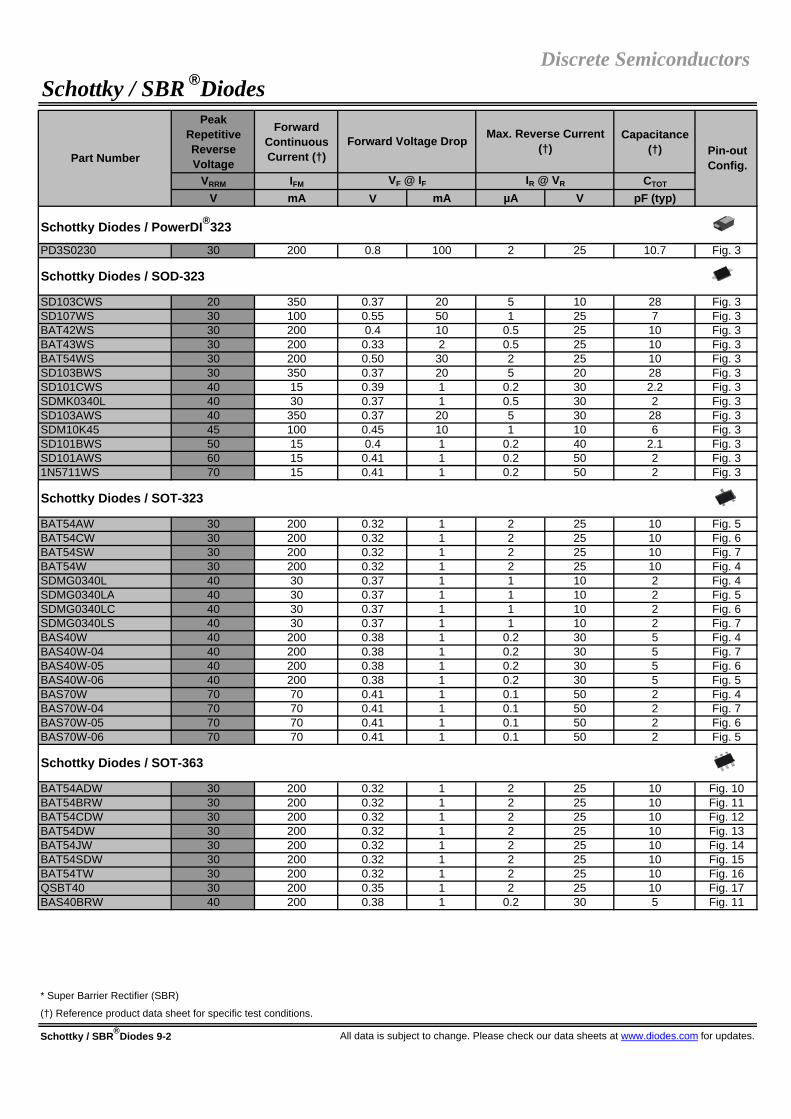
Peak Repetitive Reverse Voltage
Forward Continuous Current (†)
Capacitance (†)
VRRM IFM CTOT
V mA V mA µA V pF (typ)
PD3S0230 30 200 0.8 100 2 25 10.7 Fig. 3
SD103CWS 20 350 0.37 20 5 10 28 Fig. 3SD107WS 30 100 0.55 50 1 25 7 Fig. 3BAT42WS 30 200 0.4 10 0.5 25 10 Fig. 3BAT43WS 30 200 0.33 2 0.5 25 10 Fig. 3BAT54WS 30 200 0.50 30 2 25 10 Fig. 3SD103BWS 30 350 0.37 20 5 20 28 Fig. 3SD101CWS 40 15 0.39 1 0.2 30 2.2 Fig. 3SDMK0340L 40 30 0.37 1 0.5 30 2 Fig. 3SD103AWS 40 350 0.37 20 5 30 28 Fig. 3SDM10K45 45 100 0.45 10 1 10 6 Fig. 3SD101BWS 50 15 0.4 1 0.2 40 2.1 Fig. 3SD101AWS 60 15 0.41 1 0.2 50 2 Fig. 31N5711WS 70 15 0.41 1 0.2 50 2 Fig. 3
BAT54AW 30 200 0.32 1 2 25 10 Fig. 5BAT54CW 30 200 0.32 1 2 25 10 Fig. 6BAT54SW 30 200 0.32 1 2 25 10 Fig. 7BAT54W 30 200 0.32 1 2 25 10 Fig. 4SDMG0340L 40 30 0.37 1 1 10 2 Fig. 4SDMG0340LA 40 30 0.37 1 1 10 2 Fig. 5SDMG0340LC 40 30 0.37 1 1 10 2 Fig. 6SDMG0340LS 40 30 0.37 1 1 10 2 Fig. 7BAS40W 40 200 0.38 1 0.2 30 5 Fig. 4BAS40W-04 40 200 0.38 1 0.2 30 5 Fig. 7BAS40W-05 40 200 0.38 1 0.2 30 5 Fig. 6BAS40W-06 40 200 0.38 1 0.2 30 5 Fig. 5BAS70W 70 70 0.41 1 0.1 50 2 Fig. 4BAS70W-04 70 70 0.41 1 0.1 50 2 Fig. 7BAS70W-05 70 70 0.41 1 0.1 50 2 Fig. 6BAS70W-06 70 70 0.41 1 0.1 50 2 Fig. 5
BAT54ADW 30 200 0.32 1 2 25 10 Fig. 10BAT54BRW 30 200 0.32 1 2 25 10 Fig. 11BAT54CDW 30 200 0.32 1 2 25 10 Fig. 12BAT54DW 30 200 0.32 1 2 25 10 Fig. 13BAT54JW 30 200 0.32 1 2 25 10 Fig. 14BAT54SDW 30 200 0.32 1 2 25 10 Fig. 15BAT54TW 30 200 0.32 1 2 25 10 Fig. 16QSBT40 30 200 0.35 1 2 25 10 Fig. 17BAS40BRW 40 200 0.38 1 0.2 30 5 Fig. 11
* Super Barrier Rectifier (SBR)
Schottky / SBR®Diodes 9-2 All data is subject to change. Please check our data sheets at www.diodes.com for updates.
Max. Reverse Current (†)
Schottky Diodes / SOT-323
Schottky Diodes / SOD-323
Part Number
Schottky Diodes / PowerDI®323
Discrete SemiconductorsSchottky / SBR ®Diodes
Forward Voltage Drop
Schottky Diodes / SOT-363
(†) Reference product data sheet for specific test conditions.
Pin-outConfig.
VF @ IF IR @ VR

Peak Repetitive Reverse Voltage
Forward Continuous Current (†)
Capacitance (†)
VRRM IFM CTOT
V mA V mA µA V pF (typ)
BAS40DW-04 40 200 0.38 1 0.2 30 5 Fig. 15BAS40DW-05 40 200 0.38 1 0.2 30 5 Fig. 12BAS40DW-06 40 200 0.38 1 0.2 30 5 Fig. 10BAS40TW 40 200 0.38 1 0.2 30 5 Fig. 16SD103ATW 40 350 0.37 20 5 30 50 Fig. 18BAS70BRW 70 70 0.41 1 0.1 50 2 Fig. 11BAS70DW-04 70 70 0.41 1 0.1 50 2 Fig. 15BAS70DW-05 70 70 0.41 1 0.1 50 2 Fig. 12BAS70DW-06 70 70 0.41 1 0.1 50 2 Fig. 10BAS70JW 70 70 0.41 1 0.1 50 2 Fig. 14BAS70TW 70 70 0.41 1 0.1 50 2 Fig. 16
SD103CW 20 350 0.37 20 5 10 28 Fig. 3BAT42W 30 200 0.4 10 0.5 25 10 Fig. 3BAT43W 30 200 0.33 2 0.5 25 10 Fig. 3SD103BW 30 350 0.37 20 5 20 28 Fig. 3SD101CW 40 15 0.39 1 0.2 30 2.2 Fig. 3SD103AW 40 350 0.37 20 5 30 28 Fig. 3SD101BW 50 15 0.4 1 0.2 40 2.1 Fig. 31N6263W 60 15 0.41 1 0.2 50 2.2 Fig. 3SD101AW 60 15 0.41 1 0.2 50 2 Fig. 31N5711W 70 15 0.41 1 0.2 50 2 Fig. 3BAT46W 100 150 0.45 10 5 75 6 Fig. 3
SDM40E20LA 20 400 0.43 500 250 20 170 Fig. 5SDM40E20LC 20 400 0.43 500 250 20 170 Fig. 6SDM40E20LS 20 400 0.43 500 250 20 170 Fig. 7BAT54 30 200 0.32 1 2 25 10 Fig. 4BAT54A 30 200 0.32 1 2 25 10 Fig. 5BAT54C 30 200 0.32 1 2 25 10 Fig. 6BAT54S 30 200 0.32 1 2 25 10 Fig. 7BAS40 40 200 0.38 1 0.2 30 5 Fig. 4BAS40-04 40 200 0.38 1 0.2 30 5 Fig. 7BAS40-05 40 200 0.38 1 0.2 30 5 Fig. 6BAS40-06 40 200 0.38 1 0.2 30 5 Fig. 5SDM20N40A 40 200 0.55 200 15 30 23 Fig. 5BAS70 70 70 0.41 1 0.1 50 2 Fig. 4BAS70-04 70 70 0.41 1 0.1 50 2 Fig. 7BAS70-05 70 70 0.41 1 0.1 50 2 Fig. 6BAS70-06 70 70 0.41 1 0.1 50 2 Fig. 5
* Super Barrier Rectifier (SBR)
All data is subject to change. Please check our data sheets at www.diodes.com for updates. Schottky / SBR®Diodes 9-3
IR @ VR
Pin-outConfig.
VF @ IF
Schottky Diodes / SOT-23
Schottky Diodes / SOD-123
Schottky / SBR ®Diodes
(†) Reference product data sheet for specific test conditions.
Discrete Semiconductors
Schottky Diodes / SOT-363 (continued)
Part NumberForward Voltage Drop Max. Reverse Current
(†)

Peak Repetitive Reverse Voltage
Forward Continuous Current (†)
Capacitance (†)
VRRM IFM CTOT
V mA V mA µA V pF (typ)
SDM20E40C 40 200 0.3 10 70 25 100 Fig. 6
SDM03MT40 40 30 0.37 1 1 10 2 Fig. 16SDM03MT40A 40 30 0.37 1 1 10 2 Fig. 18SD103ASDM 40 350 0.37 20 5 30 50 Fig. 15SDM10M45SD 45 100 0.45 10 0.07 10 6 Fig. 15
* Super Barrier Rectifier (SBR)
Schottky / SBR®Diodes 9-4 All data is subject to change. Please check our data sheets at www.diodes.com for updates.
Schottky Diodes / SC-59
Schottky Diodes / SOT-26
Part Number Pin-outConfig.
VF @ IF IR @ VR
(†) Reference product data sheet for specific test conditions.
Discrete SemiconductorsSchottky / SBR ®Diodes
Forward Voltage Drop Max. Reverse Current (†)

* Super Barrier Rectifier (SBR)
All data is subject to change. Please check our data sheets at www.diodes.com for updates. Schottky / SBR®Diodes 9-5
Figure 16SOT-363, SOT-26
Figure 17SOT-363
Figure 18SOT-363, SOT-26
(†) Reference product data sheet for specific test conditions.
Figure 10SOT-363
Figure 11SOT-363
Figure 12SOT-363
Figure 13SOT-363
Figure 14SOT-363
Figure 15SOT-363, SOT-26
Figure 5SOT-23, SOT-323, SOT-523
Figure 6SOT-23, SOT-323, SOT-523, SC-59
Figure 7SOT-23, SOT-323, SOT-523
Figure 8 SOT-563
Figure 9 SOT-563
Figure 4SOT-23, SOT-323, SOT-523
Figure 1DFN1006-2, DFN1006H4-2
Figure 2DFN1616-6
Figure 3
PowerDI®323, SOD-523, SOD-323, SOD-123
Schottky / SBR®Diodes Configurations
Discrete SemiconductorsSchottky / SBR ®Diodes

Peak Repetitive Reverse Voltage
Peak Forward Surge
Current (†)
VRRM IFSM
V A ºC A V A mA V
SBR05U20LP* 20 0.5 - 5 0.5 0.5 0.02 20 Fig. 1
B0520WS 20 0.5 25 2 0.43 0.5 0.25 20 Fig. 2B0530WS 30 0.5 25 2 0.45 0.5 0.5 30 Fig. 2B0540WS 40 0.5 25 3 0.55 0.5 0.005 30 Fig. 2
BAT400D 40 0.5 25 3 0.55 0.5 0.05 30 Fig. 3
B0520LW 20 0.5 90 5.5 0.385 0.5 0.25 20 Fig. 2B0530W 30 0.5 100 5.5 0.43 0.5 0.13 30 Fig. 2B0540W 40 0.5 115 5.5 0.51 0.5 0.02 40 Fig. 2
BAT750 40 0.75 25 5.5 0.49 0.75 0.1 30 Fig. 3
PD3S120L 20 1 80** 33 0.42 1 0.16 20 Fig. 2PD3S130H 30 1 100** 22 0.55 1 0.1 30 Fig. 2PD3S130L 30 1 87** 22 0.42 1 0.8 30 Fig. 2PD3S140 40 1 87** 25 0.55 1 0.05 40 Fig. 2PD3S160 60 1 75** 22 0.64 1 0.1 60 Fig. 2
BAT760 30 1 25 5.5 0.55 1 0.05 15 Fig. 2SBR130S3* 30 1 - 20 0.46 1 0.05 30 Fig. 2SDM100K30L 30 1 25 9 0.485 1 0.1 20 Fig. 2SBR140S3* 40 1 - 20 0.49 1 0.03 40 Fig. 2
DFLS120L 20 1 - 50 0.36 1 1 20 Fig. 2DFLS130 30 1 - 35 0.42 1 1 30 Fig. 2DFLS130L 30 1 - 50 0.36 1.5 1 30 Fig. 2DFLS140L 40 1 120 50 0.55 1 0.5 40 Fig. 2DFLS140 40 1.1 119 40 0.51 0.5 0.02 40 Fig. 2DFLS160 60 1 - 50 0.5 1 0.1 60 Fig. 2DFLS1100 100 1 120** 40 0.77 1 0.001 100 Fig. 2DFLS1150 150 1 - 50 0.82 1 0.002 150 Fig. 2DFLS1200 200 1 87** 40 0.85 1 0.002 200 Fig. 2
* Super Barrier Rectifier (SBR)** Based on Derating of ambient temperature, Ta (FR-4 PCB, 2 oz. Copper)*** Based on Derating of ambient temperature, Ta (Polymide PCB, 2 oz. Copper)
All data is subject to change. Please check our data sheets at www.diodes.com for updates. Surface Mount Schottky / SBR®Rectifiers 10-1
Max. Average Rectified Current (†)
IO @ TT
Pin-out Config.
0.75A Schottky Rectifiers / SOT-23
1.0A Schottky Rectifiers / PowerDI®323
Part Number
Forward Voltage Drop
VF @ IF
Max. Reverse Current (†)
IR @ VR
1.0A Super Barrier Rectifiers (SBR) / Schottky Rectifiers / SOD-323
1.0A Schottky Rectifiers / PowerDI®123
Surface Mount Schottky / SBR ® RectifiersDiscrete Semiconductors
0.5A Super Barrier Rectifiers (SBR) / DFN1006-2
0.5A Schottky Rectifiers / SOD-323
0.5A Schottky Rectifiers / SOT-23
0.5A Schottky Rectifiers / SOD-123

Peak Repetitive Reverse Voltage
Peak Forward Surge
Current (†)
VRRM IFSM
V A ºC A V A mA V
B130LAW 30 1 25 12 0.42 1 1 30 Fig. 21N5819HW 40 1 90 25 0.45 1 1 40 Fig. 2B140HW 40 1 60 6.6 0.55 1 0.04 40 Fig. 2
BAT1000 40 1 25 5.5 0.5 1 0.1 30 Fig. 3
B120 20 1 130 30 0.5 1 0.5 20 Fig. 2B130 30 1 130 30 0.5 1 0.5 30 Fig. 2B130L 30 1 105 25 0.41 1 1 30 Fig. 2B140 40 1 130 30 0.5 1 0.5 40 Fig. 2B150 50 1 130 30 0.7 1 0.5 50 Fig. 2B160 60 1 130 30 0.7 1 0.5 60 Fig. 2B170 70 1 125 30 0.79 1 0.5 70 Fig. 2B180 80 1 125 30 0.79 1 0.5 80 Fig. 2B190 90 1 125 30 0.79 1 0.5 90 Fig. 2B1100 100 1 125 30 0.79 1 0.5 100 Fig. 2
B120B 20 1 130 30 0.5 1 0.5 20 Fig. 2B130B 30 1 130 30 0.5 1 0.5 30 Fig. 2B130LB 30 1 120 40 0.4 1 1 30 Fig. 2B140B 40 1 130 30 0.5 1 0.5 40 Fig. 2B140HB 40 1 115 45 0.53 1 0.1 40 Fig. 2B150B 50 1 130 30 0.7 1 0.5 50 Fig. 2B160B 60 1 130 30 0.7 1 0.5 60 Fig. 2B170B 70 1 125 30 0.79 1 0.5 70 Fig. 2B180B 80 1 125 30 0.79 1 0.5 80 Fig. 2B190B 90 1 125 30 0.79 1 0.5 90 Fig. 2B1100B 100 1 125 30 0.79 1 0.5 100 Fig. 2B1100LB 100 1 120 50 0.75 1 0.5 100 Fig. 2
DFLS220L 20 2 - 40 0.42 2 1 20 Fig. 2DFLS230 30 2 120 22 0.49 2 1 30 Fig. 2DFLS230L 30 2 121 33 0.42 2 1 30 Fig. 2DFLS230LH 30 2 50** 75 0.45 2 0.2 30 Fig. 2SBR2A30P1* 30 2 63*** 75 0.45 2 0.2 30 Fig. 2SBR2M30P1* 30 2 75** 75 0.46 2 0.2 30 Fig. 2SBR2U30P1* 30 2 25** 75 0.4 2 0.4 30 Fig. 2DFLS240 40 2 50** 40 0.7 2 6 40 Fig. 2DFLS240L 40 2 - 50 0.55 2 0.5 40 Fig. 2SBR2A40P1* 40 2 50** 50 0.5 2 0.1 40 Fig. 2
* Super Barrier Rectifier (SBR)** Based on Derating of ambient temperature, Ta (FR-4 PCB, 2 oz. Copper)*** Based on Derating of ambient temperature, Ta (Polymide PCB, 2 oz. Copper)
Surface Mount Schottky / SBR®Rectifiers 10-2 All data is subject to change. Please check our data sheets at www.diodes.com for updates.
Part Number
Max. Average Rectified Current (†)
Forward Voltage Drop
Max. Reverse Current (†) Pin-out
Config.IO @ TT VF @ IF IR @ VR
1.0A Schottky Rectifiers / SOT-23
1.0A Schottky Rectifiers / SMA
Discrete SemiconductorsSurface Mount Schottky / SBR ® Rectifiers
1.0A Schottky Rectifiers / SMB
2.0A Super Barrier Rectifiers (SBR) / Schottky Rectifiers / PowerDI®123
1.0A Schottky Rectifiers / SOD-123

Peak Repetitive Reverse Voltage
Peak Forward Surge
Current (†)
VRRM IFSM
V A ºC A V A mA V
B220A 20 2 100 50 0.5 2 0.5 20 Fig. 2B230A 30 2 100 50 0.5 2 0.5 30 Fig. 2SBR2U30SA* 30 2 - 75 0.4 2 0.4 30 Fig. 2B240A 40 2 100 50 0.5 2 0.5 40 Fig. 2B250A 50 2 100 50 0.7 2 0.5 50 Fig. 2B260A 60 2 100 50 0.7 2 0.5 60 Fig. 2
B220 20 2 100 50 0.5 2 0.5 20 Fig. 2B230 30 2 100 50 0.5 2 0.5 30 Fig. 2B240 40 2 100 50 0.5 2 0.5 40 Fig. 2B250 50 2 100 50 0.7 2 0.5 50 Fig. 2B260 60 2 100 50 0.7 2 0.5 60 Fig. 2B270 70 2 125 50 0.79 2 0.5 70 Fig. 2B280 80 2 125 50 0.79 2 0.5 80 Fig. 2B290 90 2 125 50 0.79 2 0.5 90 Fig. 2B2100 100 2 125 50 0.79 2 0.5 100 Fig. 2
SBR3M30P1 30 3 25*** 75 0.5 3 0.2 30 Fig. 2SBR3U30P1 30 3 25*** 75 0.43 3 0.4 30 Fig. 2SBR3U40P1 40 3 25*** 75 0.49 3 0.4 40 Fig. 2
B3L30LP 30 3 - 30 0.45 3 1 30 Fig. 4SBR3U100LP* 100 3 - 30 0.72 3 0.2 100 Fig. 4SBR3U150LP* 150 3 - 30 0.82 3 0.25 150 Fig. 4
PDS340 40 3 40 90 0.49 3 0.5 40 Fig. 5PDS360 60 3 55 100 0.62 3 0.15 60 Fig. 5PDS3100 100 3 25 90 0.75 3 0.2 100 Fig. 5PDS3200 200 3 75 180 0.78 3 0.01 200 Fig. 5
B320A 20 3 100 100 0.50 3 0.5 20 Fig. 2B330A 30 3 100 100 0.50 3 0.5 30 Fig. 2B340A 40 3 100 100 0.50 3 0.5 40 Fig. 2B340LA 40 3 90 70 0.45 3 2 40 Fig. 2SBR3A40SA* 40 3 - 120 0.50 3 0.4 40 Fig. 2B350A 50 3 100 100 0.70 3 0.5 50 Fig. 2B360A 60 3 100 100 0.70 3 0.5 60 Fig. 2
* Super Barrier Rectifier (SBR)** Based on Derating of ambient temperature, Ta (FR-4 PCB, 2 oz. Copper)*** Based on Derating of ambient temperature, Ta (Polymide PCB, 2 oz. Copper)
All data is subject to change. Please check our data sheets at www.diodes.com for updates. Surface Mount Schottky / SBR®Rectifiers 10-3
3.0A Super Barrier Rectifiers (SBR) / Schottky Rectifiers / DFN3030-8
IO @ TT VF @ IF IR @ VR
3.0A Super Barrier Rectifiers (SBR) / Schottky Rectifiers / SMA
2.0A Super Barrier Rectifiers (SBR) / Schottky Rectifiers / SMA
2.0A Schottky Rectifiers / SMB
Discrete Semiconductors
Part Number
Max. Average Rectified Current (†)
Forward Voltage Drop
Max. Reverse Current (†) Pin-out
Config.
3.0A Super Barrier Rectifiers (SBR) / PowerDI®123
3.0A Schottky Rectifiers / PowerDI®5
Surface Mount Schottky / SBR ® Rectifiers

Peak Repetitive Reverse Voltage
Peak Forward Surge
Current (†)
VRRM IFSM
V A ºC A V A mA V
B320B 20 3 100 125 0.5 3 0.5 20 Fig. 2B330B 30 3 100 125 0.5 3 0.5 30 Fig. 2B340B 40 3 100 125 0.5 3 0.5 40 Fig. 2B340LB 40 3 90 70 0.45 3 2 40 Fig. 2B350B 50 3 100 125 0.7 3 0.5 50 Fig. 2B360B 60 3 100 125 0.7 3 0.5 60 Fig. 2
B320 20 3 100 125 0.5 3 0.5 20 Fig. 2B330 30 3 100 125 0.5 3 0.5 30 Fig. 2B340 40 3 100 125 0.5 3 0.5 40 Fig. 2B350 50 3 100 125 0.7 3 0.5 50 Fig. 2B360 60 3 100 125 0.7 3 0.5 60 Fig. 2B370 70 3 90 100 0.79 3 0.5 70 Fig. 2B380 80 3 90 100 0.79 3 0.5 80 Fig. 2B390 90 3 90 100 0.79 3 0.5 90 Fig. 2B3100 100 3 90 100 0.79 3 0.5 100 Fig. 2
PDS4150 150 4 35*** 180 0.76 4 0.01 150 Fig. 5
PDS540 40 5 25*** 120 0.52 5 0.3 40 Fig. 5PDS560 60 5 25*** 120 0.67 5 0.2 60 Fig. 5PDS5100 100 5 - 120 0.78 5 0.2 100 Fig. 5PDS5100H 100 5 30*** 250 0.71 5 0.01 100 Fig. 5
B520C 20 5 90 175 0.55 5 0.5 20 Fig. 2B530C 30 5 90 175 0.55 5 0.5 30 Fig. 2B540C 40 5 90 175 0.55 5 0.5 40 Fig. 2B550C 50 5 90 175 0.7 5 0.5 50 Fig. 2B560C 60 5 90 175 0.7 5 0.5 60 Fig. 2
PDS760 60 7 50*** 275 0.62 7 0.2 60 Fig. 5
PDS835L 35 8 - 120 0.51 8 1.4 35 Fig. 5
PDS1040 40 10 - 275 0.51 10 0.7 40 Fig. 5PDS1040CTL 40 10 25*** 110 0.5 5 0.2 40 Fig. 6PDS1040L 40 10 35*** 275 0.49 10 0.6 40 Fig. 5PDS1045 45 10 35*** 275 0.51 10 0.6 45 Fig. 5* Super Barrier Rectifier (SBR)** Based on Derating of ambient temperature, Ta (FR-4 PCB, 2 oz. Copper)*** Based on Derating of ambient temperature, Ta (Polymide PCB, 2 oz. Copper)
Surface Mount Schottky / SBR®Rectifiers 10-4 All data is subject to change. Please check our data sheets at www.diodes.com for updates.
Max. Reverse Current (†)
IO @ TT VF @ IF IR @ VR
5.0A Schottky Rectifiers / PowerDI®5
5.0A Schottky Rectifiers / SMC
7.0A Schottky Rectifiers / PowerDI®5
8.0A Schottky Rectifiers / PowerDI®5
10.0A Schottky Rectifiers / PowerDI®5
3.0A Schottky Rectifiers / SMB
3.0A Schottky Rectifiers / SMC
4.0A Schottky Rectifiers / PowerDI®5
Discrete SemiconductorsSurface Mount Schottky / SBR ® Rectifiers
Pin-out Config.Part Number
Max. Average Rectified Current (†)
Forward Voltage Drop

Peak Repetitive Reverse Voltage
Peak Forward Surge
Current (†)
VRRM IFSM
V A ºC A V A mA V
SBG1025L 25 10 120 200 0.45 10 1 25 Fig. 7SBG1030L 30 10 120 200 0.45 10 1 30 Fig. 7
SBG1030CT 30 10 95 125 0.55 5 1 30 Fig. 8SBG1035CT 35 10 95 125 0.55 5 1 35 Fig. 8SBG1040CT 40 10 95 125 0.55 5 1 40 Fig. 8SBG1045CT 45 10 95 125 0.55 5 1 45 Fig. 8SBR10U200CTB* 200 10 135 150 0.82 5 0.2 200 Fig. 8
MBRB1530CT 30 15 105 150 0.7 7.5 0.1 30 Fig. 8MBRB1535CT 35 15 105 150 0.7 7.5 0.1 35 Fig. 8MBRB1540CT 40 15 105 150 0.7 7.5 0.1 40 Fig. 8MBRB1545CT 45 15 105 150 0.7 7.5 0.1 45 Fig. 8
SBG1630CT 30 16 95 175 0.55 8 1 30 Fig. 8SBG1635CT 35 16 95 175 0.55 8 1 35 Fig. 8SBG1640CT 40 16 95 175 0.55 8 1 40 Fig. 8SBG1645CT 45 16 95 175 0.55 8 1 45 Fig. 8
SBG2030CT 30 20 105 225 0.55 10 1 30 Fig. 8SBG2035CT 35 20 105 225 0.55 10 1 35 Fig. 8SBG2040CT 40 20 105 225 0.55 10 1 40 Fig. 8SBG2045CT 45 20 105 225 0.55 10 1 45 Fig. 8SBR20A200CTB* 200 20 - 180 0.86 10 0.1 200 Fig. 8SBR20A300CTB* 300 20 - 180 0.92 10 0.1 300 Fig. 8
SBG3030CT 30 30 100 250 0.55 15 1 30 Fig. 8SBG3040CT 40 30 100 250 0.55 15 1 40 Fig. 8SBG3045CT 45 30 100 250 0.55 15 1 45 Fig. 8SBG3050CT 50 30 100 250 0.7 15 1 50 Fig. 8SBG3060CT 60 30 100 250 0.7 15 1 60 Fig. 8
* Super Barrier Rectifier (SBR)** Based on Derating of ambient temperature, Ta (FR-4 PCB, 2 oz. Copper)*** Based on Derating of ambient temperature, Ta (Polymide PCB, 2 oz. Copper)
All data is subject to change. Please check our data sheets at www.diodes.com for updates. Surface Mount Schottky / SBR®Rectifiers 10-5
20.0A Super Barrier Rectifiers (SBR) / Schottky Rectifiers (Dual) / D2Pak
30.0A Schottky Rectifiers (Dual) / D2Pak
15.0A Schottky Rectifiers (Dual) / D2Pak
16.0A Schottky Rectifiers (Dual) / D2Pak
Part Number
Max. Average Rectified Current (†)
Forward Voltage Drop
Max. Reverse Current (†) Pin-out
Config.IO @ TT VF @ IF IR @ VR
10.0A Super Barrier Rectifiers (SBR) / Schottky Rectifiers (Dual) / D2Pak
10.0A Schottky Rectifiers (Single) / D2Pak
Discrete SemiconductorsSurface Mount Schottky / SBR ® Rectifiers

Surface Mount Schottky / SBR®Rectifiers 10-6 All data is subject to change. Please check our data sheets at www.diodes.com for updates.
Figure 5
Single PowerDI®5
Figure 6
Dual PowerDI®5
Figure 7Single D2PAK
Figure 8Dual Common Cathode D2PAK
Discrete SemiconductorsSurface Mount Schottky / SBR ® Rectifiers
Schottky Rectifier Configurations
Figure 1DFN1006-2
Figure 2
PowerDI®123, PowerDI®323, SOD-323, SOD-123, SMA, SMB, SMC
Figure 3SOT-23
Figure 4DFN3030-8
Note: Left & Right pins must be electricallyconnected at the printedcircuit board.

Peak Repetitive Reverse Voltage
Peak Forward
Surge Current (†)
VRRM IFSM
V A oC A V A mA V
1N5817 20 1.0 90 25 0.45 1.0 10 20SB120 20 1.0 100** 40 0.5 1.0 0.5 201N5818 30 1.0 90 25 0.55 1.0 10 30SB130 30 1.0 100** 40 0.5 1.0 0.5 301N5819 40 1.0 90 25 0.6 1.0 10 40SB140 40 1.0 100** 40 0.5 1.0 0.5 40SB150 50 1.0 75** 40 0.7 1.0 0.5 50SB160 60 1.0 75** 40 0.7 1.0 0.5 60SB170 70 1.0 85** 25 0.8 1.0 0.5 70SB180 80 1.0 85** 25 0.8 1.0 0.5 80SB190 90 1.0 85** 25 0.8 1.0 0.5 90SB1100 100 1.0 85** 25 0.8 1.0 0.5 100
1N5820 20 3.0 95 80 0.85 3.0 20 20SB320 20 3.0 100** 80 0.5 3.0 0.5 201N5821 30 3.0 95 80 0.9 3.0 20 30SB330 30 3.0 100** 80 0.5 3.0 0.5 301N5822 40 3.0 95 80 0.95 3.0 20 40SB340 40 3.0 100** 80 0.5 3.0 0.5 40SB350 50 3.0 75** 80 0.74 3.0 0.5 50SB360 60 3.0 75** 80 0.74 3.0 0.5 60SB370 70 3.0 80** 80 0.79 3.0 0.5 70SB380 80 3.0 80** 80 0.79 3.0 0.5 80SB390 90 3.0 80** 80 0.79 3.0 0.5 90SB3100 100 3.0 80** 80 0.79 3.0 0.5 100
SB520 20 5.0 90** 150 0.55 5.0 0.5 20SB530 30 5.0 90** 150 0.55 5.0 0.5 30SB540 40 5.0 90** 150 0.55 5.0 0.5 40SB550 50 5.0 65** 150 0.67 5.0 0.5 50SB560 60 5.0 65** 150 0.67 5.0 0.5 60SB570 70 5.0 80** 150 0.8 5.0 0.5 70SB580 80 5.0 80** 150 0.8 5.0 0.5 80SB590 90 5.0 80** 150 0.8 5.0 0.5 90SB5100 100 5.0 80** 150 0.8 5.0 0.5 100
SBL530 30 5.0 95 175 0.55 5.0 0.5 30SBL535 35 5.0 95 175 0.55 5.0 0.5 35SBL540 40 5.0 95 175 0.55 5.0 0.5 40SBL545 45 5.0 95 175 0.55 5.0 0.5 45SBL550 50 5.0 95 175 0.7 5.0 0.5 50SBL560 60 5.0 95 175 0.7 5.0 0.5 60
** Lead Temperature(†) Reference product data sheet for specific test conditions.
All data is subject to change. Please check our data sheets at www.diodes.com for updates. Through-Hole Schottky / SBR® Rectifiers 11-1
VF @ IF IR @ VR
Type Number
IO @ TC
Discrete Semiconductors
Max. AverageRectified Current (†)
Max. Forward Voltage Drop
Max. Reverse Current (†)
Through-Hole Schottky / SBR ®Rectifiers
1.0A Schottky Rectifiers / DO-41
3.0A Schottky Rectifiers / DO-201AD
5.0A Schottky Rectifiers / DO-201AD
5.0A Schottky Rectifiers / TO-220AC

Peak Repetitive Reverse Voltage
Peak Forward
Surge Current (†)
VRRM IFSM
V A oC A V A mA V
MBR730 30 7.5 125 150 0.84 15.0 0.1 30MBR735 35 7.5 125 150 0.84 15.0 0.1 35MBR740 40 7.5 125 150 0.84 15.0 0.1 40MBR745 45 7.5 125 150 0.84 15.0 0.1 45MBR750 50 7.5 125 150 0.65 7.5 0.5 50MBR760 60 7.5 125 150 0.65 7.5 0.5 60
SD830 30 8.0 90 175 0.55 8.0 1 30SD840 40 8.0 90 175 0.55 8.0 1 40SD845 45 8.0 90 175 0.55 8.0 1 45SD860 60 8.0 90 175 0.7 8.0 1 60
SBL830 30 8.0 95 200 0.55 8.0 0.5 30SBL835 35 8.0 95 200 0.55 8.0 0.5 35SBL840 40 8.0 95 200 0.55 8.0 0.5 40SBL845 45 8.0 95 200 0.55 8.0 0.5 45SBL850 50 8.0 95 200 0.7 8.0 0.5 50SBL860 60 8.0 95 200 0.7 8.0 0.5 60
SD930 30 9.0 120** 340 0.48 9.0 0.8 30SD940 40 9.0 120** 340 0.48 9.0 0.8 40SD945 45 9.0 120** 340 0.48 9.0 0.8 45
MBR1030 30 10.0 125 150 0.84 10.0 0.1 30SBL1030 30 10.0 95 250 0.6 10.0 1 30MBR1035 35 10.0 125 150 0.84 10.0 0.1 35SBL1035 35 10.0 95 250 0.6 10.0 1 35MBR1040 40 10.0 125 150 0.84 10.0 0.1 40SBL1040 40 10.0 95 250 0.6 10.0 1 40MBR1045 45 10.0 125 150 0.84 10.0 0.1 45SBL1045 45 10.0 95 250 0.6 10.0 1 45MBR1050 50 10.0 125 150 0.95 10.0 0.1 50SBL1050 50 10.0 95 250 0.75 10.0 1 50MBR1060 60 10.0 125 150 0.95 10.0 0.1 60SBL1060 60 10.0 95 250 0.75 10.0 1 60
** Lead Temperature(†) Reference product data sheet for specific test conditions.
Through-Hole Schottky / SBR® Rectifiers 11-2 All data is subject to change. Please check our data sheets at www.diodes.com for updates.
Discrete SemiconductorsThrough-Hole Schottky / SBR ®Rectifiers
Type Number
Max. AverageRectified Current (†)
Max. Forward Voltage Drop
Max. Reverse Current (†)
IO @ TC VF @ IF IR @ VR
7.5A Schottky Rectifiers / TO-220AC
8.0A Schottky Rectifiers / TO-220AC
9.0A Schottky Rectifiers / DO-201AD
8.0A Schottky Rectifiers / DO-201AD
10.0A Schottky Rectifiers / TO-220AC

Peak Repetitive Reverse Voltage
Peak Forward
Surge Current (†)
VRRM IFSM
V A oC A V A mA V
MBR1030CT 30 10.0 105 125 0.7 5.0 0.1 30SBL1030CT 30 10.0 95 175 0.55 5.0 0.5 30MBR1035CT 35 10.0 105 125 0.7 5.0 0.1 35SBL1035CT 35 10.0 95 175 0.55 5.0 0.5 35MBR1040CT 40 10.0 105 125 0.7 5.0 0.1 40SBL1040CT 40 10.0 95 175 0.55 5.0 0.5 40SBR1040CT* 40 10.0 - 120 0.55 5.0 0.5 40SBR10U40CT* 40 10.0 110 150 0.44 5.0 0.5 40MBR1045CT 45 10.0 105 125 0.7 5.0 0.1 45SBL1045CT 45 10.0 95 175 0.55 5.0 0.5 45MBR1050CT 50 10.0 105 125 0.8 5.0 0.1 50SBL1050CT 50 10.0 95 175 0.7 5.0 0.5 50MBR1060CT 60 10.0 105 125 0.8 5.0 0.1 60SBL1060CT 60 10.0 95 175 0.7 5.0 0.5 60SBR1060CT* 60 10.0 - 120 0.68 5.0 0.5 60SBR10U60CT* 60 10.0 110 150 0.48 5.0 0.5 60MBR1070CT 70 10.0 100 120 0.85 5.0 0.1 70MBR1080CT 80 10.0 100 120 0.85 5.0 0.1 80MBR1090CT 90 10.0 100 120 0.85 5.0 0.1 90MBR10100CT 100 10.0 100 120 0.85 5.0 0.1 70SBR10100CT* 100 10.0 - 120 0.8 5.0 0.2 100SBR10U100CT* 100 10.0 140 150 0.67 5.0 0.2 100SBR10150CT* 150 10.0 - 120 0.92 5.0 0.25 150SBR10U150CT* 150 10.0 140 150 0.79 5.0 0.2 150SBR10U200CT* 200 10.0 140 150 0.82 5.0 0.2 200SBR10U300CT* 300 10.0 150 150 0.86 5.0 0.2 300
SBR1040CTFP 40 10.0 - 120 0.55 5.0 0.5 40SBR10U40CTFP 40 10.0 110 150 0.44 5.0 0.5 40SBR1060CTFP 60 10.0 - 120 0.68 5.0 0.5 60SBR10U60CTFP 60 10.0 110 150 0.48 5.0 0.5 60SBR10100CTFP 100 10.0 - 120 0.8 5.0 0.2 100SBR10U100CTFP 100 10.0 140 150 0.67 5.0 0.2 100SBR10150CTFP 150 10.0 - 120 0.92 5.0 0.25 150SBR10U150CTFP 150 10.0 140 150 0.79 5.0 0.2 150SBR10U200CTFP 200 10.0 140 150 0.82 5.0 0.2 200SBR10U300CTFP 300 10.0 150 150 0.86 5.0 0.2 300
MBR1530CT 30 15.0 125 150 0.84 15.0 0.1 30MBR1535CT 35 15.0 125 150 0.84 15.0 0.1 35MBR1540CT 40 15.0 125 150 0.84 15.0 0.1 40MBR1545CT 45 15.0 125 150 0.84 15.0 0.1 45MBR1550CT 50 15.0 125 150 0.9 15.0 1 50MBR1560CT 60 15.0 125 150 0.9 15.0 1 60
* Super Barrier Rectifier (SBR)(†) Reference product data sheet for specific test conditions.
All data is subject to change. Please check our data sheets at www.diodes.com for updates. Through-Hole Schottky / SBR® Rectifiers 11-3
Discrete SemiconductorsThrough-Hole Schottky / SBR ®Rectifiers
Type Number
Max. AverageRectified Current (†)
Max. Forward Voltage Drop
Max. Reverse Current (†)
IO @ TC VF @ IF IR @ VR
10.0A Super Barrier Rectifiers (SBR) (Dual) / ITO-220AB
10.0A Super Barrier Rectifiers (SBR) & Schottky Rectifiers (Dual) / TO-220AB
15.0A Schottky Rectifiers (Dual) / TO-220AB

Peak Repetitive Reverse Voltage
Peak Forward
Surge Current (†)
VRRM IFSM
V A oC A V A mA V
MBR1630 30 16.0 125 150 0.63 16.0 0.2 30SBL1630 30 16.0 95 275 0.57 16.0 1 30MBR1635 35 16.0 125 150 0.63 16.0 0.2 35SBL1635 35 16.0 95 275 0.57 16.0 1 35MBR1640 40 16.0 125 150 0.63 16.0 0.2 40SBL1640 40 16.0 95 275 0.57 16.0 1 40MBR1645 45 16.0 125 150 0.63 16.0 0.2 45SBL1645 45 16.0 95 275 0.57 16.0 1 45MBR1650 50 16.0 125 150 0.75 16.0 1 50SBL1650 50 16.0 95 275 0.75 16.0 1 50MBR1660 60 16.0 125 150 0.75 16.0 1 60SBL1660 60 16.0 95 275 0.75 16.0 1 60
SBL1630CT 30 16.0 95 250 0.55 8.0 0.5 30SBL1635CT 35 16.0 95 250 0.55 8.0 0.5 35SBL1640CT 40 16.0 95 250 0.55 8.0 0.5 40SBL1645CT 45 16.0 95 250 0.55 8.0 0.5 45SBL1650CT 50 16.0 95 250 0.7 8.0 0.5 50SBL1660CT 60 16.0 95 250 0.7 8.0 0.5 60
SBL1630PT 30 16.0 95 250 0.55 8.0 0.5 30SBL1635PT 35 16.0 95 250 0.55 8.0 0.5 35SBL1640PT 40 16.0 95 250 0.55 8.0 0.5 40SBL1645PT 45 16.0 95 250 0.55 8.0 0.5 45SBL1650PT 50 16.0 95 250 0.7 8.0 0.5 50SBL1660PT 60 16.0 95 250 0.7 8.0 0.5 60
MBR2030CT 30 20.0 125 150 0.84 20.0 0.1 30SBL2030CT 30 20.0 95 250 0.55 10.0 1 30MBR2035CT 35 20.0 125 150 0.84 20.0 0.1 35SBL2035CT 35 20.0 95 250 0.55 10.0 1 35MBR2040CT 40 20.0 125 150 0.84 20.0 0.1 40SBL2040CT 40 20.0 95 250 0.55 10.0 1 40SBR2040CT* 40 20.0 110 120 0.53 10.0 0.5 40SBR20A40CT* 40 20.0 110 180 0.5 10.0 0.5 40SBR20U40CT* 40 20.0 110 200 0.47 10.0 0.5 40MBR2045CT 45 20.0 125 150 0.84 20.0 0.1 45SBL2045CT 45 20.0 95 250 0.55 10.0 1 45SBR2045CT* 45 20.0 110 120 0.54 10.0 0.5 45SBR20A45CT* 45 20.0 110 180 0.5 10.0 0.5 45MBR2050CT 50 20.0 125 150 0.95 20.0 0.1 50SBL2050CT 50 20.0 95 250 0.75 10.0 1 50
* Super Barrier Rectifier (SBR)(†) Reference product data sheet for specific test conditions.
Through-Hole Schottky / SBR® Rectifiers 11-4 All data is subject to change. Please check our data sheets at www.diodes.com for updates.
Discrete SemiconductorsThrough-Hole Schottky / SBR ®Rectifiers
Type Number
Max. AverageRectified Current (†)
Max. Forward Voltage Drop
Max. Reverse Current (†)
IO @ TC VF @ IF IR @ VR
16.0A Schottky Rectifiers (Dual) / TO-3P
20.0A Super Barrier Rectifiers (SBR) & Schottky Rectifiers (Dual) / TO-220AB
16.0A Schottky Rectifiers (Dual) / TO-220AB
16.0A Schottky Rectifiers / TO-220AC

Peak Repetitive Reverse Voltage
Peak Forward
Surge Current (†)
VRRM IFSM
V A oC A V A mA V
MBR2060CT 60 20.0 125 150 0.95 20.0 0.1 60SBL2060CT 60 20.0 95 250 0.75 10.0 1 60SBR2060CT* 60 20.0 110 150 0.7 10.0 0.5 60SBR20A60CT* 60 20.0 110 180 0.65 10.0 0.5 60SBR20U60CT* 60 20.0 110 200 0.57 10.0 0.5 60MBR2070CT 70 20.0 125 150 0.95 20.0 0.15 70MBR2080CT 80 20.0 125 150 0.95 20.0 0.15 80MBR2090CT 90 20.0 125 150 0.95 20.0 0.15 90MBR20100CT 100 20.0 125 150 0.95 20.0 0.15 100SBR20100CT* 100 20.0 150 150 0.82 10.0 0.1 100SBR20A100CT* 100 20.0 150 180 0.75 10.0 0.1 100SBR20U100CT* 100 20.0 140 200 0.7 10.0 0.5 100SBR20A120CT* 120 20.0 150 180 0.8 10.0 0.1 120SBR20150CT* 150 20.0 150 150 0.88 10.0 0.1 150SBR20A150CT* 150 20.0 150 180 0.82 10.0 0.1 150SBR20U150CT* 150 20.0 140 200 0.78 10.0 0.5 150SBR20A200CT* 200 20.0 150 180 0.86 10.0 0.1 200SBR20A300CT* 300 20.0 150 180 0.92 10.0 0.1 300
SBR2040CTFP 40 20.0 110 120 0.53 10.0 0.5 40SBR20A40CTFP 40 20.0 110 180 0.5 10.0 0.5 40SBR20U40CTFP 40 20.0 110 200 0.47 10.0 0.5 40SBR2045CTFP 45 20.0 110 120 0.54 10.0 0.5 45SBR20A45CTFP 45 20.0 110 180 0.5 10.0 0.5 45SBR2060CTFP 60 20.0 110 150 0.7 10.0 0.5 60SBR20A60CTFP 60 20.0 110 180 0.65 10.0 0.5 60SBR20U60CTFP 60 20.0 110 200 0.57 10.0 0.5 60SBR20100CTFP 100 20.0 150 150 0.82 10.0 0.1 100SBR20A100CTFP 100 20.0 150 180 0.75 10.0 0.1 100SBR20U100CTFP 100 20.0 140 200 0.7 10.0 0.5 100SBR20150CTFP 150 20.0 150 150 0.88 10.0 0.1 150SBR20A150CTFP 150 20.0 150 180 0.82 10.0 0.1 150SBR20U150CTFP 150 20.0 140 200 0.78 10.0 0.5 150SBR20A200CTFP 200 20.0 150 180 0.86 10.0 0.1 200SBR20A300CTFP 300 20.0 150 180 0.92 10.0 0.1 300
SBL2030PT 30 20.0 100 250 0.55 10.0 1 30SBL2035PT 35 20.0 100 250 0.55 10.0 1 35SBL2040PT 40 20.0 100 250 0.55 10.0 1 40SBL2045PT 45 20.0 100 250 0.55 10.0 1 45SBL2050PT 50 20.0 100 250 0.75 10.0 1 50SBL2060PT 60 20.0 100 250 0.75 10.0 1 60
* Super Barrier Rectifier (SBR)(†) Reference product data sheet for specific test conditions.
All data is subject to change. Please check our data sheets at www.diodes.com for updates. Through-Hole Schottky / SBR® Rectifiers 11-5
20.0A Super Barrier Rectifiers (SBR) & Schottky Rectifiers (Dual) / TO-220AB (continued)
Discrete SemiconductorsThrough-Hole Schottky / SBR ®Rectifiers
Type Number
Max. AverageRectified Current (†)
Max. Forward Voltage Drop
Max. Reverse Current (†)
IO @ TC VF @ IF IR @ VR
20.0A Super Barrier Rectifiers (SBR) (Dual) / ITO-220AB
20.0A Schottky Rectifiers (Dual) / TO-3P

Peak Repetitive Reverse Voltage
Peak Forward
Surge Current (†)
VRRM IFSM
V A oC A V A mA V
SBR30U30CT 30 30.0 - 280 0.45 15.0 1.5 30SBR3040CT 40 30.0 110 200 0.55 15.0 0.5 40SBR30A40CT 40 30.0 110 250 0.5 15.0 0.5 40SBR3045CT 45 30.0 110 200 0.55 15.0 0.5 45SBR30A45CT 45 30.0 110 250 0.5 15.0 0.5 45SBR3060CT 60 30.0 110 200 0.7 15.0 0.5 60SBR30A60CT 60 30.0 110 250 0.6 15.0 0.5 60SBR30100CT 100 30.0 150 200 0.85 15.0 0.1 100SBR30A100CT 100 30.0 150 250 0.8 15.0 0.1 100SBR30M100CT 100 30.0 175 250 0.85 15.0 0.012 100SBR30150CT 150 30.0 150 200 0.92 15.0 0.1 150SBR30A120CT 120 30.0 120 250 0.83 15.0 0.1 120SBR30A150CT 150 30.0 150 250 0.88 15.0 0.1 150SBR30200CT 200 30.0 150 200 0.98 15.0 0.1 200SBR30300CT 300 30.0 150 200 1.03 15.0 0.1 300
SBR3040CTFP 40 30.0 110 200 0.55 15.0 0.5 40SBR30A40CTFP 40 30.0 110 250 0.5 15.0 0.5 40SBR3045CTFP 45 30.0 110 200 0.55 15.0 0.5 45SBR30A45CTFP 45 30.0 110 250 0.5 15.0 0.5 45SBR3060CTFP 60 30.0 110 200 0.7 15.0 0.5 60SBR30A60CTFP 60 30.0 110 250 0.6 15.0 0.5 60SBR30100CTFP 100 30.0 150 200 0.85 15.0 0.1 100SBR30A100CTFP 100 30.0 150 250 0.8 15.0 0.1 100SBR30M100CTFP 100 30.0 175 250 0.85 15.0 0.012 100SBR30150CTFP 150 30.0 150 200 0.92 15.0 0.1 150SBR30A150CTFP 150 30.0 150 250 0.88 15.0 0.1 150SBR30200CTFP 200 30.0 150 200 0.98 15.0 0.1 200SBR30300CTFP 300 30.0 150 200 1.03 15.0 0.1 300
MBR3030PT 30 30.0 125 200 0.76 30.0 1 30SBL3030PT 30 30.0 95 275 0.55 15.0 1 30MBR3035PT 35 30.0 125 200 0.76 30.0 5 35SBL3035PT 35 30.0 95 275 0.55 15.0 1 35MBR3040PT 40 30.0 125 200 0.76 30.0 5 40SBL3040PT 40 30.0 95 275 0.55 15.0 1 40MBR3045PT 45 30.0 125 200 0.76 30.0 1 45SBL3045PT 45 30.0 95 275 0.55 15.0 1 45MBR3050PT 50 30.0 125 200 0.8 30.0 5 50SBL3050PT 50 30.0 95 275 0.7 15.0 1 50MBR3060PT 60 30.0 125 200 0.8 30.0 5 60SBL3060PT 60 30.0 95 275 0.7 15.0 1 60
* Super Barrier Rectifier (SBR)(†) Reference product data sheet for specific test conditions.
Through-Hole Schottky / SBR® Rectifiers 11-6 All data is subject to change. Please check our data sheets at www.diodes.com for updates.
Type Number
Max. AverageRectified Current (†)
Max. Forward Voltage Drop
Max. Reverse Current (†)
IO @ TC VF @ IF IR @ VR
Discrete SemiconductorsThrough-Hole Schottky / SBR ®Rectifiers
30.0A Schottky Rectifiers (Dual) / TO-3P
30.0A Super Barrier Rectifiers (SBR) (Dual) / TO-220AB
30.0A Super Barrier Rectifiers (SBR) (Dual) / ITO-220AB

Peak Repetitive Reverse Voltage
Peak Forward
Surge Current (†)
VRRM IFSM
V A oC A V A mA V
SBR4040CT 40 40.0 110 280 0.53 20.0 0.5 40SBR4045CT 45 40.0 110 280 0.55 20.0 0.5 45SBR40U45CT 45 40.0 110 280 0.47 20.0 1 45SBR4060CT 60 40.0 110 280 0.7 20.0 0.5 60SBR40U60CT 60 40.0 110 280 0.58 20.0 0.5 60SBR40100CT 100 40.0 150 280 0.82 20.0 0.1 100SBR40U100CT 100 40.0 - 280 0.72 20.0 0.5 100SBR40150CT 150 40.0 150 280 0.9 20.0 0.1 150
SBR4040CTFP 40 40.0 110 280 0.53 20.0 0.5 40SBR4045CTFP 45 40.0 110 280 0.55 20.0 0.5 45SBR4060CTFP 60 40.0 110 280 0.7 20.0 0.5 60SBR40100CTFP 100 40.0 150 280 0.82 20.0 0.1 100SBR40150CTFP 150 40.0 150 280 0.9 20.0 0.1 150
MBR4030PT 30 40.0 125 400 0.7 20.0 1 30SBL4030PT 30 40.0 100 375 0.58 20.0 1 30MBR4035PT 35 40.0 125 400 0.7 20.0 1 35SBL4035PT 35 40.0 100 375 0.58 20.0 1 35MBR4040PT 40 40.0 125 400 0.7 20.0 1 40SBL4040PT 40 40.0 100 375 0.58 20.0 1 40MBR4045PT 45 40.0 125 400 0.7 20.0 1 45SBL4045PT 45 40.0 100 375 0.58 20.0 1 45MBR4050PT 50 40.0 125 400 0.8 20.0 1 50SBL4050PT 50 40.0 100 375 0.7 20.0 1 50MBR4060PT 60 40.0 125 400 0.8 20.0 1 60SBL4060PT 60 40.0 100 375 0.7 20.0 1 60
SBR60A60CT 60 60.0 - 280 0.62 30.0 0.2 60SBR60A300CT 300 60.0 - 280 0.95 30.0 0.1 300
* Super Barrier Rectifier (SBR)(†) Reference product data sheet for specific test conditions.
All data is subject to change. Please check our data sheets at www.diodes.com for updates. Through-Hole Schottky / SBR® Rectifiers 11-7
Discrete SemiconductorsThrough-Hole Schottky / SBR ®Rectifiers
Type Number
Max. AverageRectified Current (†)
Max. Forward Voltage Drop
Max. Reverse Current (†)
IO @ TC VF @ IF IR @ VR
40.0 Super Barrier Rectifiers (SBR) (Dual) / ITO-220AB
40.0 Super Barrier Rectifiers (SBR) (Dual) / TO-220AB
40.0A Schottky Rectifiers (Dual) / TO-3P
60.0 Super Barrier Rectifiers (SBR) (Dual) / TO-220AB

Peak Repetitive Reverse Voltage
Peak Forward
Surge Current (†)
VRRM IFSM
V A oC A V A mA V
MBR6030PT 30 60.0 125 500 0.62 30.0 1 30SBL6030PT 30 60.0 100 500 0.55 30.0 20 30MBR6035PT 35 60.0 125 500 0.62 30.0 1 35MBR6040PT 40 60.0 125 500 0.62 30.0 1 40SBL6040PT 40 60.0 100 500 0.55 30.0 20 40MBR6045PT 45 60.0 125 500 0.62 30.0 1 45SBL6050PT 50 60.0 100 500 0.7 30.0 20 50SBL6060PT 60 60.0 100 500 0.7 30.0 20 60
(†) Reference product data sheet for specific test conditions.
Through-Hole Schottky / SBR® Rectifiers 11-8 All data is subject to change. Please check our data sheets at www.diodes.com for updates.
60.0A Schottky Rectifiers (Dual) / TO-3P
Through-Hole Schottky Rectifiers Configurations
TO-220AC TO-220AB, TO-3P
Discrete SemiconductorsThrough-Hole Schottky / SBR ®Rectifiers
Type Number
Max. AverageRectified Current (†)
Max. Forward Voltage Drop
Max. Reverse Current (†)
IO @ TC VF @ IF IR @ VR

Peak Repetitive Reverse Voltage
Max. Average Rectified
Current (†)
Max. Reverse
Recovery Time (†)
VRRM IO trr
V mA V mA µA V ns pF V
BAS16LP 75 200 1 50 1 75 4 2 0 Fig. 171N4448HLP 80 125 1 100 0.1 80 4 3 0.5 Fig. 17
1N4448HWT 80 125 1 100 0.1 80 4 3 0.5 Fig. 181N4148WT 100 125 1 50 1 75 4 2 0 Fig. 18
MMBD4448HT 80 250 1 100 0.1 70 4 3.5 6 Fig. 1MMBD4448HTA 80 250 1 100 0.1 70 4 3.5 6 Fig. 4MMBD4448HTC 80 250 1 100 0.1 70 4 3.5 6 Fig. 2MMBD4448HTS 80 250 1 100 0.1 70 4 3.5 6 Fig. 3BAS16T 85 155* 1 50 2 75 4 - - Fig. 1BAV70T 85 155* 1 50 2 75 4 - - Fig. 2BAV99T 85 155* 1 50 2 75 4 - - Fig. 3BAW56T 85 155* 1 50 2 75 4 - - Fig. 4BAS21T 250 200* 1 100 0.1 250 50 5 0 Fig. 1
BAS116T 85 215* 1.1 50 0.005 75 3000 - - Fig. 1BAV170T 85 215* 1.1 50 0.005 75 3000 - - Fig. 2BAV199T 85 215* 1.1 50 0.005 75 3000 - - Fig. 3BAW156T 85 215* 1.1 50 0.005 75 3000 - - Fig. 4
BAS16V 75 200 1 50 1 75 4 2 0 Fig. 15MMBD4448V 80 250 1 100 0.1 70 4 3.5 6 Fig. 15
BAS116V 85 215 1.1 50 0.005 75 3000 - - Fig. 15
PD3SD2580 80 250* 1 100 0.1 80 4 2.5 0 Fig. 18
1N4148WS 75 150 1 50 1 75 4 2 0 Fig. 181N4448WS 75 250 1 100 2.5 75 4 4 0 Fig. 18BAV16WS 75 150 1 50 1 75 4 2 0 Fig. 181N4448HWS 80 250 1 100 0.1 80 4 3.5 0 Fig. 18BAV19WS 100 200 1 100 0.1 120 50 5 0 Fig. 18BAV20WS 150 200 1 100 0.1 200 50 5 0 Fig. 18BAV21WS 200 200 1 100 0.1 250 50 5 0 Fig. 18BAV3004WS 350 225 1 100 0.1 240 50 5 0 Fig. 18
* Forward Continuous Current, IFM
(†) Reference product data sheet for specific test conditions.
All data is subject to change. Please check our data sheets at www.diodes.com for updates. Switching Diodes 12-1
Switching Diodes / PowerDI®323
Switching Diodes / SOD-523
Switching Diodes / SOD-323
Low Leakage Signal Diodes / SOT-563
Max. Forward Voltage Drop
Max. Reverse Current
IR @ VRVF @ IF
Switching Diodes / DFN1006-2
Switching Diodes / SOT-523
Discrete Semiconductors
Part Number
Max. Total Capacitance Pin-out
Config.
CT @ VR
Switching Diodes
Low Leakage Signal Diodes / SOT-523
Switching Diodes / SOT-563

Peak Repetitive Reverse Voltage
Max. Average Rectified
Current (†)
Max. Reverse
Recovery Time (†)
VRRM IO trr
V mA V mA µA V ns pF V
BAS16W 75 150 1 50 1 75 4 2 0 Fig. 1BAV70W 75 150 1 50 2.5 75 4 2 0 Fig. 2BAV99W 75 150 1 50 2.5 75 4 2 0 Fig. 3BAW56W 75 150 1 50 2.5 75 4 2 0 Fig. 4MMBD4148W 75 150 1 50 1 75 4 2 0 Fig. 1MMBD4448W 75 250 1 100 2.5 75 4 4 0 Fig. 1MMBD4448HW 80 250 1 100 0.1 70 4 3.5 6 Fig. 1BAS19W 120 200 1 100 0.1 120 50 5 0 Fig. 1BAS20W 200 200 1 100 0.1 200 50 5 0 Fig. 1BAS21W 250 200 1 100 0.1 250 50 5 0 Fig. 1MMBD2004SW 300 225 1 100 0.1 240 50 5 0 Fig. 3
BAV199W 85 160 1.1 50 0.005 75 3000 - - Fig. 3
MMBD4448HCQW 80 250 1 100 0.1 70 4 3.5 6 Fig. 13
BAS16TW 75 150 1 50 1 75 4 2 0 Fig. 6BAV70DW 75 150 1 50 2.5 75 4 2 0 Fig. 7BAV756DW 75 150 1 50 2.5 75 4 2 0 Fig. 8BAV99BRW 75 150 1 50 2.5 75 4 2 0 Fig. 9BAV99DW 75 215* 1 50 2.5 75 4 2 0 Fig. 10BAW567DW 75 150 1 50 2.5 75 4 2 0 Fig. 16BAW56DW 75 150 1 50 2.5 75 4 2 0 Fig. 11MMBD4148TW 75 150 1 50 1 75 4 2 0 Fig. 6MMBD4448DW 75 250 1 50 2.5 75 4 4 0 Fig. 15SDA006 75 215* 1 50 2.5 75 4 2 0 Fig. 19MMBD4448HADW 80 250 1 100 0.1 70 4 3.5 6 Fig. 11MMBD4448HAQW 80 250 1 100 0.1 70 4 3.5 6 Fig. 12MMBD4448HCDW 80 250 1 100 0.1 70 4 3.5 6 Fig. 7MMBD4448HSDW 80 250 1 100 0.1 70 4 3.5 6 Fig. 10MMBD4448HTW 80 250 1 100 0.1 70 4 3.5 6 Fig. 6SDA004 80 500* 1 100 0.1 70 4 - - Fig. 10BAS20DW 200 200 1 100 0.1 200 50 5 0 Fig. 15BAS21DW 250 200 1 100 0.1 250 50 5 0 Fig. 15
BAV199DW 85 160 1.1 50 0.005 75 3000 - - Fig. 10DLPA006 85 80 1.1 50 0.005 75 3000 - - Fig. 19
* Forward Continuous Current, IFM
(†) Reference product data sheet for specific test conditions.
Switching Diodes 12-2 All data is subject to change. Please check our data sheets at www.diodes.com for updates.
Discrete Semiconductors
Pin-outConfig.
Switching Diodes
Part Number
VF @ IF IR @ VR CT @ VR
Switching Diodes / SOT-323
Low Leakage Signal Diodes / SOT-323
Switching Diodes / SOT-363
Switching Diodes / SOT-353
Low Leakage Signal Diodes / SOT-363
Max. Forward Voltage Drop
Max. Reverse Current
Max. Total Capacitance

Peak Repetitive Reverse Voltage
Max. Average Rectified
Current (†)
Max. Reverse
Recovery Time (†)
VRRM IO trr
V mA V mA µA V ns pF V
1N4448W 75 250 1 100 2.5 75 4 4 0 Fig. 181N4148W 100 150 1 50 1 75 4 2 0 Fig. 18BAV16W 100 150 1 50 1 75 4 2 0 Fig. 18BAV19W 100 200 1 100 0.1 120 50 5 0 Fig. 18BAV20W 150 200 1 100 0.1 200 50 5 0 Fig. 18BAV21W 200 200 1 100 0.1 250 50 5 0 Fig. 18BAV3004W 350 225* 1 100 0.1 240 50 5 0 Fig. 18
BAV116W 130 215* 1.1 50 0.005 75 3000 5 0 Fig. 18
BAL99 75 300* 1 50 2.5 75 4 2 0 Fig. 5BAS16 75 200 1 50 1 75 4 2 0 Fig. 1BAV70 75 150 1 50 2.5 75 4 2 0 Fig. 2BAV99 75 300* 1 50 2.5 75 4 2 0 Fig. 3BAW56 75 300* 1 50 2.5 75 4 2 0 Fig. 4MMBD4148 75 200 1 50 1 75 4 2 0 Fig. 1MMBD4448 75 250 1 100 2.5 75 4 4 0 Fig. 1MMBD7000 75 300* 1.1 50 1 50 4 2 0 Fig. 3MMBD914 75 200 1 50 1 75 4 2 0 Fig. 1MMBD4448H 80 250 1 100 0.1 70 4 3.5 6 Fig. 1BAS19 120 200 1 100 0.1 120 50 5 0 Fig. 1BAS20 200 200 1 100 0.1 200 50 5 0 Fig. 1BAS21 250 200 1 100 0.1 250 50 5 0 Fig. 1BAV23A 250 400 1 100 0.1 250 50 5 0 Fig. 4BAV23C 250 400 1 100 0.1 250 50 5 0 Fig. 2BAV23S 250 400 1 100 0.1 250 50 5 0 Fig. 3MMBD2004S 300 225 1 100 0.1 240 50 5 0 Fig. 3MMBD3004A 350 225 1.25 200 0.1 240 50 5 0 Fig. 4MMBD3004C 350 225 1.25 200 0.1 240 50 5 0 Fig. 2MMBD3004S 350 225 1.25 200 0.1 240 50 5 0 Fig. 3
BAS116 85 215** 1.1 50 0.005 75 3000 - - Fig. 1BAV170 85 215** 1.1 50 0.005 75 3000 - - Fig. 2BAV199 85 160** 1.1 50 0.005 75 3000 - - Fig. 3BAW156 85 160** 1.1 50 0.005 75 3000 - - Fig. 4
MMBD4448HTM 80 250 1 100 0.1 70 4 3.5 6 Fig. 14MMBD3004BRM 350 225* 1.25 200 0.1 240 50 5 0 Fig. 9
* Forward Continuous Current, IFM
** Power Dissipation, P = 250mW(†) Reference product data sheet for specific test conditions.
All data is subject to change. Please check our data sheets at www.diodes.com for updates. Switching Diodes 12-3
Max. Total Capacitance Pin-out
Config.
VF @ IF IR @ VR
Low Leakage Signal Diodes / SOT-23
Switching Diodes / SOT-26
Switching Diodes / SOD-123
CT @ VR
Low Leakage Signal Diodes / SOD-123
Switching Diodes / SOT-23
Discrete SemiconductorsSwitching Diodes
Part Number
Max. Forward Voltage Drop
Max. Reverse Current

Switching Diodes 12-4 All data is subject to change. Please check our data sheets at www.diodes.com for updates.
Figure 7SOT-363
Figure 10SOT-363
Discrete SemiconductorsSwitching Diodes
Figure 18
PowerDI®323, SOD-123, SOD-323, SOD-523
Figure 12SOT-363
Figure 3SOT-23, SOT-323, SOT-523
Figure 2SOT-23, SOT-323, SOT-523
Figure 19SOT-363
Figure 15SOT-363, SOT-563
Figure 14SOT-26
Figure 1SOT-23, SOT-323, SOT-523
Figure 13SOT-353
Figure 16SOT-363
Figure 17DFN1006-2
Figure 11SOT-363
Figure 8SOT-363
Figure 9SOT-363, SOT-26
Figure 4SOT-23, SOT-323, SOT-523
Switching Diode Configurations
Figure 6SOT-363
Figure 5SOT-23

IZT
Nom. V Min. V Max. V mA µA V
BZT52C2V4LP 2.4 2.2 2.6 5 50 1 Fig. 10BZT52C2V7LP 2.7 2.5 2.9 5 20 1 Fig. 10BZT52C3V0LP 3.0 2.8 3.2 5 10 1 Fig. 10BZT52C3V3LP 3.3 3.1 3.5 5 5 1 Fig. 10BZT52C3V6LP 3.6 3.4 3.8 5 5 1 Fig. 10BZT52C3V9LP 3.9 3.7 4.1 5 3 1 Fig. 10BZT52C4V3LP 4.3 4.0 4.6 5 3 1 Fig. 10BZT52C4V7LP 4.7 4.4 5.0 5 3 1 Fig. 10BZT52C5V1LP 5.1 4.8 5.4 5 2 2 Fig. 10BZT52C5V6LP 5.6 5.2 6.0 5 1 2 Fig. 10BZT52C6V2LP 6.2 5.8 6.6 5 3 4 Fig. 10BZT52C6V8LP 6.8 6.4 7.2 5 2 4 Fig. 10BZT52C7V5LP 7.5 7.0 7.9 5 1 5 Fig. 10BZT52C8V2LP 8.2 7.7 8.7 5 0.7 5 Fig. 10BZT52C9V1LP 9.1 8.5 9.6 5 0.5 6 Fig. 10BZT52C10LP 10 9.4 10.6 5 0.2 7 Fig. 10BZT52C11LP 11 10.4 11.6 5 0.1 8 Fig. 10BZT52C12LP 12 11.4 12.7 5 0.1 8 Fig. 10BZT52C13LP 13 12.4 14.1 5 0.1 8 Fig. 10BZT52C15LP 15 13.8 15.6 5 0.1 10.5 Fig. 10BZT52C16LP 16 15.3 17.1 5 0.1 11.2 Fig. 10BZT52C18LP 18 16.8 19.1 5 0.1 12.6 Fig. 10BZT52C20LP 20 18.8 21.2 5 0.1 14.0 Fig. 10BZT52C22LP 22 20.8 23.3 5 0.1 15.4 Fig. 10BZT52C24LP 24 22.8 25.6 5 0.1 16.8 Fig. 10BZT52C36LP 36 34 38 2 0.1 25.2 Fig. 10BZT52C39LP 39 37 41 2 0.1 27.3 Fig. 10
BZT52C2V0T 2.0 1.91 2.09 5 150 1 Fig. 1BZT52C2V4T 2.4 2.2 2.6 5 50 1 Fig. 1BZT52C2V7T 2.7 2.5 2.9 5 20 1 Fig. 1BZT52C3V0T 3.0 2.8 3.2 5 10 1 Fig. 1BZT52C3V3T 3.3 3.1 3.5 5 5 1 Fig. 1BZT52C3V6T 3.6 3.4 3.8 5 5 1 Fig. 1BZT52C3V9T 3.9 3.7 4.1 5 3 1 Fig. 1BZT52C4V3T 4.3 4.0 4.6 5 3 1 Fig. 1BZT52C4V7T 4.7 4.4 5.0 5 3 2 Fig. 1BZT52C5V1T 5.1 4.8 5.4 5 2 2 Fig. 1BZT52C5V6T 5.6 5.2 6.0 5 1 2 Fig. 1BZT52C6V2T 6.2 5.8 6.6 5 3 4 Fig. 1BZT52C6V8T 6.8 6.4 7.2 5 2 4 Fig. 1BZT52C7V5T 7.5 7.0 7.9 5 1 5 Fig. 1BZT52C8V2T 8.2 7.7 8.7 5 0.7 5 Fig. 1BZT52C9V1T 9.1 8.5 9.6 5 0.5 6 Fig. 1BZT52C10T 10 9.4 10.6 5 0.2 7 Fig. 1BZT52C11T 11 10.4 11.6 5 0.1 8 Fig. 1BZT52C12T 12 11.4 12.7 5 0.1 8 Fig. 1
1. Short duration pulse test used to minimize self-heating effect.
All data is subject to change. Please check our data sheets at www.diodes.com for updates. Zener Diodes 13-1
VZ @ IZT
Max. Reverse Leakage Current
IR @ VR
250mW Zener Diodes (Single) / DFN1006-2
150mW Zener Diodes (Single) / SOD-523
Discrete SemiconductorsZener Diodes
Pin-outConfig.Part Number
Zener Voltage Range1

IZT
Nom. V Min. V Max. V mA µA V
BZT52C13T 13 12.4 14.1 5 0.1 8 Fig. 1BZT52C15T 15 13.8 15.6 5 0.1 10.5 Fig. 1BZT52C16T 16 15.3 17.1 5 0.1 11.2 Fig. 1BZT52C18T 18 16.8 19.1 5 0.1 12.6 Fig. 1BZT52C20T 20 18.8 21.2 5 0.1 14.0 Fig. 1BZT52C22T 22 20.8 23.3 5 0.1 15.4 Fig. 1BZT52C24T 24 22.8 25.6 5 0.1 16.8 Fig. 1
DDZ9689T 5.1 4.85 5.36 0.05 5 3 Fig. 1DDZ9690T 5.6 5.32 5.88 0.05 2 4 Fig. 1DDZ9691T 6.2 5.89 6.51 0.05 1 5 Fig. 1DDZ9692T 6.8 6.46 7.14 0.05 0.1 5.1 Fig. 1DDZ9693T 7.5 7.13 7.88 0.05 0.1 5.7 Fig. 1DDZ9694T 8.2 7.79 8.61 0.05 0.1 6.2 Fig. 1DDZ9696T 9.1 8.65 9.56 0.05 0.1 6.9 Fig. 1DDZ9697T 10 9.50 10.50 0.05 0.1 7.6 Fig. 1DDZ9698T 11 10.45 11.55 0.05 0.05 8.4 Fig. 1DDZ9699T 12 11.40 12.60 0.05 0.05 9.1 Fig. 1DDZ9700T 13 12.35 13.65 0.05 0.05 9.8 Fig. 1DDZ9701T 14 13.30 14.70 0.05 0.05 10.6 Fig. 1DDZ9702T 15 14.25 15.75 0.05 0.05 11.4 Fig. 1DDZ9703T 16 15.20 16.80 0.05 0.05 12.1 Fig. 1DDZ9705T 18 17.10 18.90 0.05 0.05 13.6 Fig. 1DDZ9707T 20 19.00 21.00 0.05 0.05 15.2 Fig. 1DDZ9708T 22 20.90 23.10 0.05 0.05 16.7 Fig. 1DDZ9709T 24 22.80 25.20 0.05 0.05 18.2 Fig. 1DDZ9711T 27 25.65 28.35 0.05 0.05 20.4 Fig. 1DDZ9712T 28 26.60 29.40 0.05 0.05 21.2 Fig. 1DDZ9713T 30 28.50 31.50 0.05 0.05 22.8 Fig. 1DDZ9714T 33 31.35 34.65 0.05 0.05 25.0 Fig. 1DDZ9715T 36 34.20 37.80 0.05 0.05 27.3 Fig. 1DDZ9716T 39 37.05 40.95 0.05 0.05 29.6 Fig. 1DDZ9717T 43 40.85 45.15 0.05 0.05 32.6 Fig. 1
BZX84C2V4T 2.4 2.2 2.6 5 50 1 Fig. 2MMBZ5221BT 2.4 2.28 2.52 20 100 1 Fig. 2BZX84C2V7T 2.7 2.5 2.9 5 20 1 Fig. 2MMBZ5223BT 2.7 2.57 2.84 20 75 1 Fig. 2BZX84C3V0T 3.0 2.8 3.2 5 10 1 Fig. 2MMBZ5225BT 3.0 2.85 3.15 20 50 1 Fig. 2BZX84C3V3T 3.3 3.1 3.5 5 5 1 Fig. 2MMBZ5226BT 3.3 3.14 3.47 20 25 1 Fig. 2BZX84C3V6T 3.6 3.4 3.8 5 5 1 Fig. 2MMBZ5227BT 3.6 3.42 3.78 20 15 1 Fig. 2BZX84C3V9T 3.9 3.7 4.1 5 3 1 Fig. 2MMBZ5228BT 3.9 3.71 4.10 20 10 1 Fig. 2
1. Short duration pulse test used to minimize self-heating effect.
Zener Diodes 13-2 All data is subject to change. Please check our data sheets at www.diodes.com for updates.
Part NumberZener Voltage Range1
150mW Low Test Current Zener Diodes (Single) / SOD-523
VZ @ IZT IR @ VR
150mW Zener Diodes (Single) / SOD-523 (continued)
Max. Reverse Leakage CurrentPin-outConfig.
150mW Zener Diodes (Single) / SOT-523
Discrete SemiconductorsZener Diodes

IZT
Nom. V Min. V Max. V mA µA V
BZX84C4V3T 4.3 4.0 4.6 5 3 1 Fig. 2MMBZ5229BT 4.3 4.09 4.52 20 5 1 Fig. 2BZX84C4V7T 4.7 4.4 5.0 5 3 2 Fig. 2MMBZ5230BT 4.7 4.47 4.94 20 5 2 Fig. 2BZX84C5V1T 5.1 4.8 5.4 5 2 2 Fig. 2MMBZ5231BT 5.1 4.85 5.36 20 5 2 Fig. 2BZX84C5V6T 5.6 5.2 6.0 5 1 2 Fig. 2MMBZ5232BT 5.6 5.32 5.88 20 5 3 Fig. 2BZX84C6V2T 6.2 5.8 6.6 5 3 4 Fig. 2MMBZ5234BT 6.2 5.89 6.51 20 5 4 Fig. 2BZX84C6V8T 6.8 6.4 7.2 5 2 4 Fig. 2MMBZ5235BT 6.8 6.46 7.14 20 3 5 Fig. 2BZX84C7V5T 7.5 7.0 7.9 5 1 5 Fig. 2MMBZ5236BT 7.5 7.13 7.88 20 3 6 Fig. 2BZX84C8V2T 8.2 7.7 8.7 5 0.7 5 Fig. 2MMBZ5237BT 8.2 7.79 8.61 20 3 6.5 Fig. 2BZX84C9V1T 9.1 8.5 9.6 5 0.5 6 Fig. 2MMBZ5239BT 9.1 8.65 9.56 20 3 7.0 Fig. 2BZX84C10T 10 9.4 10.6 5 0.2 7 Fig. 2MMBZ5240BT 10 9.50 10.50 20 3 8.0 Fig. 2BZX84C11T 11 10.4 11.6 5 0.1 8 Fig. 2MMBZ5241BT 11 10.45 11.55 20 2 8.4 Fig. 2BZX84C12T 12 11.4 12.7 5 0.1 8 Fig. 2MMBZ5242BT 12 11.40 12.60 20 1 9.1 Fig. 2BZX84C13T 13 12.4 14.1 5 0.1 8 Fig. 2MMBZ5243BT 13 12.35 13.65 9.5 0.5 9.9 Fig. 2BZX84C15T 15 13.8 15.6 5 0.1 10.5 Fig. 2MMBZ5245BT 15 14.25 15.75 8.5 0.1 11 Fig. 2BZX84C16T 16 15.3 17.1 5 0.1 11.2 Fig. 2MMBZ5246BT 16 15.20 16.80 7.8 0.1 12 Fig. 2BZX84C18T 18 16.8 19.1 5 0.1 12.6 Fig. 2MMBZ5248BT 18 17.10 18.90 7 0.1 14 Fig. 2BZX84C20T 20 18.8 21.2 5 0.1 14.0 Fig. 2MMBZ5250BT 20 19.00 21.00 6.2 0.1 15 Fig. 2BZX84C22T 22 20.8 23.3 5 0.1 15.4 Fig. 2MMBZ5251BT 22 20.90 23.10 5.6 0.1 17 Fig. 2BZX84C24T 24 22.8 25.6 5 0.1 16.8 Fig. 2MMBZ5252BT 24 22.80 25.20 5.2 0.1 18 Fig. 2BZX84C27T 27 25.1 28.9 2 0.1 18.9 Fig. 2MMBZ5254BT 27 25.65 28.35 5 0.1 21 Fig. 2MMBZ5255BT 28 26.60 29.40 4.5 0.1 21 Fig. 2BZX84C30T 30 28 32 2 0.1 21.0 Fig. 2MMBZ5256BT 30 28.50 31.50 4.2 0.1 23 Fig. 2BZX84C33T 33 31 35 2 0.1 23.1 Fig. 2MMBZ5257BT 33 31.35 34.65 3.8 0.1 25 Fig. 2BZX84C36T 36 34 38 2 0.1 25.2 Fig. 2MMBZ5258BT 36 34.20 37.80 3.4 0.1 27 Fig. 2BZX84C39T 39 37 41 2 0.1 27.3 Fig. 2MMBZ5259BT 39 37.05 40.95 3.2 0.1 30 Fig. 2
1. Short duration pulse test used to minimize self-heating effect.
All data is subject to change. Please check our data sheets at www.diodes.com for updates. Zener Diodes 13-3
Part NumberMax. Reverse Leakage Current
VZ @ IZT IR @ VR
Zener Voltage Range1
150mW Zener Diodes (Single) / SOT-523 (continued)
Pin-outConfig.
Discrete SemiconductorsZener Diodes

IZT
Nom. V Min. V Max. V mA µA V
QZX563C6V8C 6.8 6.47 7.14 1 1 3 Fig. 9
BZT52C2V0S 2.0 1.91 2.09 5 150 1 Fig. 1BZT52C2V4S 2.4 2.2 2.6 5 50 1 Fig. 1MMSZ5221BS 2.4 2.28 2.52 20 100 1 Fig. 1BZT52C2V7S 2.7 2.5 2.9 5 20 1 Fig. 1MMSZ5223BS 2.7 2.57 2.84 20 75 1 Fig. 1BZT52C3V0S 3.0 2.8 3.2 5 10 1 Fig. 1MMSZ5225BS 3.0 2.85 3.15 20 50 1 Fig. 1BZT52C3V3S 3.3 3.1 3.5 5 5 1 Fig. 1MMSZ5226BS 3.3 3.14 3.47 20 25 1 Fig. 1BZT52C3V6S 3.6 3.4 3.8 5 5 1 Fig. 1MMSZ5227BS 3.6 3.42 3.78 20 15 1 Fig. 1BZT52C3V9S 3.9 3.7 4.1 5 3 1 Fig. 1MMSZ5228BS 3.9 3.71 4.10 20 10 1 Fig. 1BZT52C4V3S 4.3 4.0 4.6 5 3 1 Fig. 1MMSZ5229BS 4.3 4.09 4.52 20 5 1 Fig. 1BZT52C4V7S 4.7 4.4 5.0 5 3 2 Fig. 1MMSZ5230BS 4.7 4.47 4.94 20 5 2 Fig. 1BZT52C5V1S 5.1 4.8 5.4 5 2 2 Fig. 1MMSZ5231BS 5.1 4.85 5.36 20 5 2 Fig. 1UDZ5V1B 5.1 4.98 5.20 5 2 1.5 Fig. 1BZT52C5V6S 5.6 5.2 6.0 5 1 2 Fig. 1MMSZ5232BS 5.6 5.32 5.88 20 5 3 Fig. 1UDZ5V6B 5.6 5.40 5.73 5 1 2.5 Fig. 1MMSZ5233BS 6.0 5.70 6.30 20 5 3.5 Fig. 1BZT52C6V2S 6.2 5.8 6.6 5 3 4 Fig. 1MMSZ5234BS 6.2 5.89 6.51 20 5 4.0 Fig. 1UDZ6V2B 6.2 6.06 6.33 5 1 3.0 Fig. 1BZT52C6V8S 6.8 6.4 7.2 5 2 4 Fig. 1MMSZ5235BS 6.8 6.46 7.14 20 3 5.0 Fig. 1UDZ6V8B 6.8 6.65 6.93 5 0.5 3.5 Fig. 1BZT52C7V5S 7.5 7.0 7.9 5 1 5 Fig. 1MMSZ5236BS 7.5 7.13 7.88 20 3 6.0 Fig. 1UDZ7V5B 7.5 7.28 7.60 5 0.5 4 Fig. 1BZT52C8V2S 8.2 7.7 8.7 5 0.7 5 Fig. 1MMSZ5237BS 8.2 7.79 8.61 20 3 6.5 Fig. 1UDZ8V2B 8.2 8.02 8.36 5 0.5 5 Fig. 1MMSZ5238BS 8.7 8.27 9.14 20 3 6.5 Fig. 1BZT52C9V1S 9.1 8.5 9.6 5 0.5 6 Fig. 1MMSZ5239BS 9.1 8.65 9.56 20 3 7.0 Fig. 1UDZ9V1B 9.1 8.85 9.23 5 0.5 6 Fig. 1BZT52C10S 10 9.4 10.6 5 0.2 7 Fig. 1MMSZ5240BS 10 9.50 10.50 20 3 8.0 Fig. 1UDZ10B 10 9.77 10.21 5 0.1 7 Fig. 1BZT52C11S 11 10.4 11.6 5 0.1 8 Fig. 1MMSZ5241BS 11 10.45 11.55 20 2 8.4 Fig. 1UDZ11B 11 10.76 11.22 5 0.1 8 Fig. 1BZT52C12S 12 11.4 12.7 5 0.1 8 Fig. 1MMSZ5242BS 12 11.40 12.60 20 1 9.1 Fig. 1
1. Short duration pulse test used to minimize self-heating effect.
Zener Diodes 13-4 All data is subject to change. Please check our data sheets at www.diodes.com for updates.
VZ @ IZT IR @ VR
Part NumberZener Voltage Range1
150mW Zener Diodes (Quad, Common Anode) / SOT-563
Max. Reverse Leakage CurrentPin-outConfig.
200mW Zener Diodes (Single) / SOD-323
Discrete SemiconductorsZener Diodes
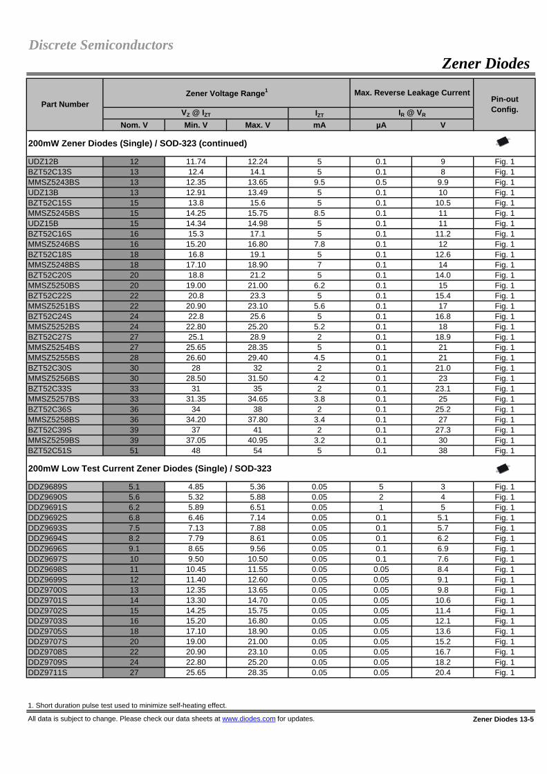
IZT
Nom. V Min. V Max. V mA µA V
UDZ12B 12 11.74 12.24 5 0.1 9 Fig. 1BZT52C13S 13 12.4 14.1 5 0.1 8 Fig. 1MMSZ5243BS 13 12.35 13.65 9.5 0.5 9.9 Fig. 1UDZ13B 13 12.91 13.49 5 0.1 10 Fig. 1BZT52C15S 15 13.8 15.6 5 0.1 10.5 Fig. 1MMSZ5245BS 15 14.25 15.75 8.5 0.1 11 Fig. 1UDZ15B 15 14.34 14.98 5 0.1 11 Fig. 1BZT52C16S 16 15.3 17.1 5 0.1 11.2 Fig. 1MMSZ5246BS 16 15.20 16.80 7.8 0.1 12 Fig. 1BZT52C18S 18 16.8 19.1 5 0.1 12.6 Fig. 1MMSZ5248BS 18 17.10 18.90 7 0.1 14 Fig. 1BZT52C20S 20 18.8 21.2 5 0.1 14.0 Fig. 1MMSZ5250BS 20 19.00 21.00 6.2 0.1 15 Fig. 1BZT52C22S 22 20.8 23.3 5 0.1 15.4 Fig. 1MMSZ5251BS 22 20.90 23.10 5.6 0.1 17 Fig. 1BZT52C24S 24 22.8 25.6 5 0.1 16.8 Fig. 1MMSZ5252BS 24 22.80 25.20 5.2 0.1 18 Fig. 1BZT52C27S 27 25.1 28.9 2 0.1 18.9 Fig. 1MMSZ5254BS 27 25.65 28.35 5 0.1 21 Fig. 1MMSZ5255BS 28 26.60 29.40 4.5 0.1 21 Fig. 1BZT52C30S 30 28 32 2 0.1 21.0 Fig. 1MMSZ5256BS 30 28.50 31.50 4.2 0.1 23 Fig. 1BZT52C33S 33 31 35 2 0.1 23.1 Fig. 1MMSZ5257BS 33 31.35 34.65 3.8 0.1 25 Fig. 1BZT52C36S 36 34 38 2 0.1 25.2 Fig. 1MMSZ5258BS 36 34.20 37.80 3.4 0.1 27 Fig. 1BZT52C39S 39 37 41 2 0.1 27.3 Fig. 1MMSZ5259BS 39 37.05 40.95 3.2 0.1 30 Fig. 1BZT52C51S 51 48 54 5 0.1 38 Fig. 1
DDZ9689S 5.1 4.85 5.36 0.05 5 3 Fig. 1DDZ9690S 5.6 5.32 5.88 0.05 2 4 Fig. 1DDZ9691S 6.2 5.89 6.51 0.05 1 5 Fig. 1DDZ9692S 6.8 6.46 7.14 0.05 0.1 5.1 Fig. 1DDZ9693S 7.5 7.13 7.88 0.05 0.1 5.7 Fig. 1DDZ9694S 8.2 7.79 8.61 0.05 0.1 6.2 Fig. 1DDZ9696S 9.1 8.65 9.56 0.05 0.1 6.9 Fig. 1DDZ9697S 10 9.50 10.50 0.05 0.1 7.6 Fig. 1DDZ9698S 11 10.45 11.55 0.05 0.05 8.4 Fig. 1DDZ9699S 12 11.40 12.60 0.05 0.05 9.1 Fig. 1DDZ9700S 13 12.35 13.65 0.05 0.05 9.8 Fig. 1DDZ9701S 14 13.30 14.70 0.05 0.05 10.6 Fig. 1DDZ9702S 15 14.25 15.75 0.05 0.05 11.4 Fig. 1DDZ9703S 16 15.20 16.80 0.05 0.05 12.1 Fig. 1DDZ9705S 18 17.10 18.90 0.05 0.05 13.6 Fig. 1DDZ9707S 20 19.00 21.00 0.05 0.05 15.2 Fig. 1DDZ9708S 22 20.90 23.10 0.05 0.05 16.7 Fig. 1DDZ9709S 24 22.80 25.20 0.05 0.05 18.2 Fig. 1DDZ9711S 27 25.65 28.35 0.05 0.05 20.4 Fig. 1
1. Short duration pulse test used to minimize self-heating effect.
All data is subject to change. Please check our data sheets at www.diodes.com for updates. Zener Diodes 13-5
Zener Diodes
Max. Reverse Leakage CurrentPin-outConfig.VZ @ IZT IR @ VR
Part NumberZener Voltage Range1
200mW Low Test Current Zener Diodes (Single) / SOD-323
Discrete Semiconductors
200mW Zener Diodes (Single) / SOD-323 (continued)

IZT
Nom. V Min. V Max. V mA µA V
DDZ9712S 28 26.60 29.40 0.05 0.05 21.2 Fig. 1DDZ9713S 30 28.50 31.50 0.05 0.05 22.8 Fig. 1DDZ9714S 33 31.35 34.65 0.05 0.05 25.0 Fig. 1DDZ9715S 36 34.20 37.80 0.05 0.05 27.3 Fig. 1DDZ9716S 39 37.05 40.95 0.05 0.05 29.6 Fig. 1DDZ9717S 43 40.85 45.15 0.05 0.05 32.6 Fig. 1
DDZ5V1BS 5.1 4.94 5.20 20 5 1.5 Fig. 1DDZ5V6BS 5.6 5.45 5.73 20 0.5 2.5 Fig. 1DDZ6V2BS 6.1 5.96 6.27 20 0.5 2.5 Fig. 1DDZ6V8CS 6.8 6.66 7.01 20 0.1 5.0 Fig. 1DDZ7V5CS 7.5 7.29 7.67 20 0.1 6.0 Fig. 1DDZ8V2CS 8.2 8.03 8.45 20 0.1 6.5 Fig. 1DDZ9V1CS 9.1 8.83 9.30 20 0.1 7.0 Fig. 1DDZ10CS 10.0 9.70 10.20 20 0.1 8.0 Fig. 1DDZ11CS 11.1 10.82 11.38 10 0.1 8.4 Fig. 1DDZ12CS 12.0 11.74 12.35 10 0.1 9.1 Fig. 1DDZ13BS 12.9 12.55 13.21 10 0.1 10 Fig. 1DDZ14S 14.0 13.65 14.35 10 0.05 11 Fig. 1DDZ15S 15.2 14.80 15.57 10 0.05 12 Fig. 1DDZ16S 16.1 15.69 16.51 10 0.05 12 Fig. 1DDZ18CS 17.9 17.42 18.33 10 0.05 14 Fig. 1DDZ20CS 19.7 19.23 20.22 10 0.05 15 Fig. 1DDZ22DS 22.1 21.52 22.63 5 0.05 17 Fig. 1DDZ24CS 23.7 23.12 24.31 5 0.05 19 Fig. 1DDZ27DS 27.0 26.29 27.64 5 0.05 21 Fig. 1DDZ30DS 29.8 29.02 30.51 5 0.05 23 Fig. 1DDZ33S 33.0 32.14 33.79 5 0.05 27 Fig. 1DDZ36S 36.3 35.36 37.19 5 0.05 30 Fig. 1DDZ39FS 39.0 38.02 39.98 5 0.05 30 Fig. 1DDZ43S 43.0 42.14 43.86 5 0.05 33 Fig. 1
PD3Z284C2V4 2.4 2.2 2.6 5 50 1 Fig. 1PD3Z284C2V7 2.7 2.5 2.9 5 20 1 Fig. 1PD3Z284C3V0 3.0 2.8 3.2 5 10 1 Fig. 1PD3Z284C3V3 3.3 3.1 3.5 5 5 1 Fig. 1PD3Z284C3V6 3.6 3.4 3.8 5 5 1 Fig. 1PD3Z284C3V9 3.9 3.7 4.1 5 3 1 Fig. 1PD3Z284C4V3 4.3 4.0 4.6 5 3 1 Fig. 1PD3Z284C4V7 4.7 4.4 5.0 5 3 2 Fig. 1PD3Z284C5V1 5.1 4.8 5.4 5 2 2 Fig. 1PD3Z284C5V6 5.6 5.2 6.0 5 1 2 Fig. 1PD3Z284C6V2 6.2 5.8 6.6 5 3 4 Fig. 1PD3Z284C6V8 6.8 6.4 7.2 5 2 4 Fig. 1PD3Z284C7V5 7.5 7.0 7.9 5 1 5 Fig. 1PD3Z284C8V2 8.2 7.7 8.7 5 0.7 5 Fig. 1PD3Z284C9V1 9.1 8.5 9.6 5 0.5 6 Fig. 1PD3Z284C10 10 9.4 10.6 5 0.2 7 Fig. 1PD3Z284C11 11 10.4 11.6 5 0.1 8 Fig. 1PD3Z284C12 12 11.4 12.7 5 0.1 8 Fig. 1
1. Short duration pulse test used to minimize self-heating effect.
Zener Diodes 13-6 All data is subject to change. Please check our data sheets at www.diodes.com for updates.
200mW Tight Breakdown Tolerance Zener Diodes (Single) / SOD-323
500mW Zener Diodes (Single) / PowerDI®323
Discrete SemiconductorsZener Diodes
Part NumberZener Voltage Range1
IR @ VR
Max. Reverse Leakage CurrentPin-outConfig.VZ @ IZT
200mW Low Test Current Zener Diodes (Single) / SOD-323 (continued)

IZT
Nom. V Min. V Max. V mA µA V
PD3Z284C13 13 12.4 14.1 5 0.1 8.0 Fig. 1PD3Z284C15 15 13.8 15.6 5 0.1 10.5 Fig. 1PD3Z284C16 16 15.3 17.1 5 0.1 11.2 Fig. 1PD3Z284C18 18 16.8 19.1 5 0.1 12.6 Fig. 1PD3Z284C20 20 18.8 21.2 5 0.1 14.0 Fig. 1PD3Z284C22 22 20.8 23.3 5 0.1 15.4 Fig. 1PD3Z284C24 24 22.8 25.6 5 0.1 16.8 Fig. 1PD3Z284C27 27 25.1 28.9 2 0.1 18.9 Fig. 1PD3Z284C30 30 28 32 2 0.1 21.0 Fig. 1PD3Z284C33 33 31 35 2 0.1 23.1 Fig. 1PD3Z284C36 36 34 38 2 0.1 25.2 Fig. 1PD3Z284C39 39 37 41 2 0.1 27.3 Fig. 1
BZX84C2V4W 2.4 2.2 2.6 5 50 1 Fig. 2MMBZ5221BW 2.4 2.28 2.52 20 100 1 Fig. 2BZX84C2V7W 2.7 2.5 2.9 5 20 1 Fig. 2MMBZ5223BW 2.7 2.57 2.84 20 75 1 Fig. 2BZX84C3V0W 3.0 2.8 3.2 5 10 1 Fig. 2MMBZ5225BW 3.0 2.85 3.15 20 50 1 Fig. 2BZX84C3V3W 3.3 3.1 3.5 5 5 1 Fig. 2MMBZ5226BW 3.3 3.14 3.47 20 25 1 Fig. 2BZX84C3V6W 3.6 3.4 3.8 5 5 1 Fig. 2MMBZ5227BW 3.6 3.42 3.78 20 15 1 Fig. 2BZX84C3V9W 3.9 3.7 4.1 5 3 1 Fig. 2MMBZ5228BW 3.9 3.71 4.10 20 10 1 Fig. 2BZX84C4V3W 4.3 4.0 4.6 5 3 1 Fig. 2MMBZ5229BW 4.3 4.09 4.52 20 5 1 Fig. 2BZX84C4V7W 4.7 4.4 5.0 5 3 2 Fig. 2MMBZ5230BW 4.7 4.47 4.94 20 5 2 Fig. 2BZX84C5V1W 5.1 4.8 5.4 5 2 2 Fig. 2MMBZ5231BW 5.1 4.85 5.36 20 5 2 Fig. 2BZX84C5V6W 5.6 5.2 6.0 5 1 2 Fig. 2MMBZ5232BW 5.6 5.32 5.88 20 5 3 Fig. 2BZX84C6V2W 6.2 5.8 6.6 5 3 4 Fig. 2MMBZ5234BW 6.2 5.89 6.51 20 5 4 Fig. 2BZX84C6V8W 6.8 6.4 7.2 5 2 4 Fig. 2MMBZ5235BW 6.8 6.46 7.14 20 3 5 Fig. 2BZX84C7V5W 7.5 7.0 7.9 5 1 5 Fig. 2MMBZ5236BW 7.5 7.13 7.88 20 3 6 Fig. 2BZX84C8V2W 8.2 7.7 8.7 5 0.7 5 Fig. 2MMBZ5237BW 8.2 7.79 8.61 20 3 6.5 Fig. 2BZX84C9V1W 9.1 8.5 9.6 5 0.5 6 Fig. 2MMBZ5239BW 9.1 8.65 9.56 20 3 7.0 Fig. 2BZX84C10W 10 9.4 10.6 5 0.2 7 Fig. 2MMBZ5240BW 10 9.50 10.50 20 3 8.0 Fig. 2BZX84C11W 11 10.4 11.6 5 0.1 8 Fig. 2MMBZ5241BW 11 10.45 11.55 20 2 8.4 Fig. 2BZX84C12W 12 11.4 12.7 5 0.1 8 Fig. 2MMBZ5242BW 12 11.40 12.60 20 1 9.1 Fig. 2BZX84C13W 13 12.4 14.1 5 0.1 8 Fig. 2
1. Short duration pulse test used to minimize self-heating effect.
All data is subject to change. Please check our data sheets at www.diodes.com for updates. Zener Diodes 13-7
Discrete SemiconductorsZener Diodes
Part NumberZener Voltage Range1 Max. Reverse Leakage Current
200mW Zener Diodes (Single) / SOT-323
IR @ VR
500mW Zener Diodes (Single) / PowerDI®323 (continued)
Pin-outConfig.VZ @ IZT
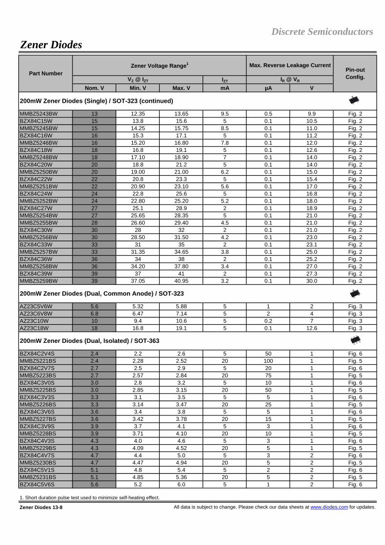
IZT
Nom. V Min. V Max. V mA µA V
MMBZ5243BW 13 12.35 13.65 9.5 0.5 9.9 Fig. 2BZX84C15W 15 13.8 15.6 5 0.1 10.5 Fig. 2MMBZ5245BW 15 14.25 15.75 8.5 0.1 11.0 Fig. 2BZX84C16W 16 15.3 17.1 5 0.1 11.2 Fig. 2MMBZ5246BW 16 15.20 16.80 7.8 0.1 12.0 Fig. 2BZX84C18W 18 16.8 19.1 5 0.1 12.6 Fig. 2MMBZ5248BW 18 17.10 18.90 7 0.1 14.0 Fig. 2BZX84C20W 20 18.8 21.2 5 0.1 14.0 Fig. 2MMBZ5250BW 20 19.00 21.00 6.2 0.1 15.0 Fig. 2BZX84C22W 22 20.8 23.3 5 0.1 15.4 Fig. 2MMBZ5251BW 22 20.90 23.10 5.6 0.1 17.0 Fig. 2BZX84C24W 24 22.8 25.6 5 0.1 16.8 Fig. 2MMBZ5252BW 24 22.80 25.20 5.2 0.1 18.0 Fig. 2BZX84C27W 27 25.1 28.9 2 0.1 18.9 Fig. 2MMBZ5254BW 27 25.65 28.35 5 0.1 21.0 Fig. 2MMBZ5255BW 28 26.60 29.40 4.5 0.1 21.0 Fig. 2BZX84C30W 30 28 32 2 0.1 21.0 Fig. 2MMBZ5256BW 30 28.50 31.50 4.2 0.1 23.0 Fig. 2BZX84C33W 33 31 35 2 0.1 23.1 Fig. 2MMBZ5257BW 33 31.35 34.65 3.8 0.1 25.0 Fig. 2BZX84C36W 36 34 38 2 0.1 25.2 Fig. 2MMBZ5258BW 36 34.20 37.80 3.4 0.1 27.0 Fig. 2BZX84C39W 39 37 41 2 0.1 27.3 Fig. 2MMBZ5259BW 39 37.05 40.95 3.2 0.1 30.0 Fig. 2
AZ23C5V6W 5.6 5.32 5.88 5 1 2 Fig. 3AZ23C6V8W 6.8 6.47 7.14 5 2 4 Fig. 3AZ23C10W 10 9.4 10.6 5 0.2 7 Fig. 3AZ23C18W 18 16.8 19.1 5 0.1 12.6 Fig. 3
BZX84C2V4S 2.4 2.2 2.6 5 50 1 Fig. 6MMBZ5221BS 2.4 2.28 2.52 20 100 1 Fig. 5BZX84C2V7S 2.7 2.5 2.9 5 20 1 Fig. 6MMBZ5223BS 2.7 2.57 2.84 20 75 1 Fig. 5BZX84C3V0S 3.0 2.8 3.2 5 10 1 Fig. 6MMBZ5225BS 3.0 2.85 3.15 20 50 1 Fig. 5BZX84C3V3S 3.3 3.1 3.5 5 5 1 Fig. 6MMBZ5226BS 3.3 3.14 3.47 20 25 1 Fig. 5BZX84C3V6S 3.6 3.4 3.8 5 5 1 Fig. 6MMBZ5227BS 3.6 3.42 3.78 20 15 1 Fig. 5BZX84C3V9S 3.9 3.7 4.1 5 3 1 Fig. 6MMBZ5228BS 3.9 3.71 4.10 20 10 1 Fig. 5BZX84C4V3S 4.3 4.0 4.6 5 3 1 Fig. 6MMBZ5229BS 4.3 4.09 4.52 20 5 1 Fig. 5BZX84C4V7S 4.7 4.4 5.0 5 3 2 Fig. 6MMBZ5230BS 4.7 4.47 4.94 20 5 2 Fig. 5BZX84C5V1S 5.1 4.8 5.4 5 2 2 Fig. 6MMBZ5231BS 5.1 4.85 5.36 20 5 2 Fig. 5BZX84C5V6S 5.6 5.2 6.0 5 1 2 Fig. 6
1. Short duration pulse test used to minimize self-heating effect.
Zener Diodes 13-8 All data is subject to change. Please check our data sheets at www.diodes.com for updates.
IR @ VR
200mW Zener Diodes (Single) / SOT-323 (continued)
200mW Zener Diodes (Dual, Common Anode) / SOT-323
VZ @ IZT
Max. Reverse Leakage Current
Zener DiodesDiscrete Semiconductors
200mW Zener Diodes (Dual, Isolated) / SOT-363
Part NumberZener Voltage Range1
Pin-outConfig.

IZT
Nom. V Min. V Max. V mA µA V
MMBZ5232BS 5.6 5.32 5.88 20 5 3 Fig. 5MMBZ5233BS 6.0 5.70 6.30 20 5 3.5 Fig. 5BZX84C6V2S 6.2 5.8 6.6 5 3 4 Fig. 6MMBZ5234BS 6.2 5.89 6.51 20 5 4.0 Fig. 5BZX84C6V8S 6.8 6.4 7.2 5 2 4 Fig. 6MMBZ5235BS 6.8 6.46 7.14 20 3 5.0 Fig. 5BZX84C7V5S 7.5 7.0 7.9 5 1 5 Fig. 6MMBZ5236BS 7.5 7.13 7.88 20 3 6.0 Fig. 5BZX84C8V2S 8.2 7.7 8.7 5 0.7 5 Fig. 6MMBZ5237BS 8.2 7.79 8.61 20 3 6.5 Fig. 5MMBZ5238BS 8.7 8.27 9.14 20 3 6.5 Fig. 5BZX84C9V1S 9.1 8.5 9.6 5 0.5 6 Fig. 6MMBZ5239BS 9.1 8.65 9.56 20 3 7.0 Fig. 5BZX84C10S 10 9.4 10.6 5 0.2 7 Fig. 6MMBZ5240BS 10 9.50 10.50 20 3 8.0 Fig. 5BZX84C11S 11 10.4 11.6 5 0.1 8 Fig. 6MMBZ5241BS 11 10.45 11.55 20 2 8.4 Fig. 5BZX84C12S 12 11.4 12.7 5 0.1 8 Fig. 6MMBZ5242BS 12 11.40 12.60 20 1 9.1 Fig. 5BZX84C13S 13 12.4 14.1 5 0.1 8 Fig. 6MMBZ5243BS 13 12.35 13.65 9.5 0.5 9.9 Fig. 5BZX84C15S 15 13.8 15.6 5 0.1 10.5 Fig. 6MMBZ5245BS 15 14.25 15.75 8.5 0.1 11 Fig. 5BZX84C16S 16 15.3 17.1 5 0.1 11.2 Fig. 6MMBZ5246BS 16 15.20 16.80 7.8 0.1 12 Fig. 5BZX84C18S 18 16.8 19.1 5 0.1 12.6 Fig. 6MMBZ5248BS 18 17.10 18.90 7 0.1 14 Fig. 5BZX84C20S 20 18.8 21.2 5 0.1 14.0 Fig. 6MMBZ5250BS 20 19.00 21.00 6.2 0.1 15 Fig. 5BZX84C22S 22 20.8 23.3 5 0.1 15.4 Fig. 6MMBZ5251BS 22 20.90 23.10 5.6 0.1 17 Fig. 5BZX84C24S 24 22.8 25.6 5 0.1 16.8 Fig. 6MMBZ5252BS 24 22.80 25.20 5.2 0.1 18 Fig. 5BZX84C27S 27 25.1 28.9 2 0.1 18.9 Fig. 6MMBZ5254BS 27 25.65 28.35 5 0.1 21 Fig. 5MMBZ5255BS 28 26.60 29.40 4.5 0.1 21 Fig. 5BZX84C30S 30 28 32 2 0.1 21.0 Fig. 6MMBZ5256BS 30 28.50 31.50 4.2 0.1 23 Fig. 5BZX84C33S 33 31 35 2 0.1 23.1 Fig. 6MMBZ5257BS 33 31.35 34.65 3.8 0.1 25 Fig. 5BZX84C36S 36 34 38 2 0.1 25.2 Fig. 6MMBZ5258BS 36 34.20 37.80 3.4 0.1 27 Fig. 5BZX84C39S 39 37 41 2 0.1 27.3 Fig. 6MMBZ5259BS 39 37.05 40.95 3.2 0.1 30 Fig. 5
1. Short duration pulse test used to minimize self-heating effect.
All data is subject to change. Please check our data sheets at www.diodes.com for updates. Zener Diodes 13-9
200mW Zener Diodes (Dual, Isolated) / SOT-363 (continued)
Discrete SemiconductorsZener Diodes
Part NumberZener Voltage Range1 Max. Reverse Leakage Current
Pin-outConfig.VZ @ IZT IR @ VR

IZT
Nom. V Min. V Max. V mA µA V
BZX84C2V4TS 2.4 2.2 2.6 5 50 1 Fig. 7MMBZ5221BTS 2.4 2.28 2.52 20 100 1 Fig. 7BZX84C2V7TS 2.7 2.5 2.9 5 20 1 Fig. 7MMBZ5223BTS 2.7 2.57 2.84 20 75 1 Fig. 7BZX84C3V0TS 3.0 2.8 3.2 5 10 1 Fig. 7MMBZ5225BTS 3.0 2.85 3.15 20 50 1 Fig. 7BZX84C3V3TS 3.3 3.1 3.5 5 5 1 Fig. 7MMBZ5226BTS 3.3 3.14 3.47 20 25 1 Fig. 7BZX84C3V6TS 3.6 3.4 3.8 5 5 1 Fig. 7MMBZ5227BTS 3.6 3.42 3.78 20 15 1 Fig. 7BZX84C3V9TS 3.9 3.7 4.1 5 3 1 Fig. 7MMBZ5228BTS 3.9 3.71 4.10 20 10 1 Fig. 7BZX84C4V3TS 4.3 4.0 4.6 5 3 1 Fig. 7MMBZ5229BTS 4.3 4.09 4.52 20 5 1 Fig. 7BZX84C4V7TS 4.7 4.4 5.0 5 3 2 Fig. 7MMBZ5230BTS 4.7 4.47 4.94 20 5 2 Fig. 7BZX84C5V1TS 5.1 4.8 5.4 5 2 2 Fig. 7MMBZ5231BTS 5.1 4.85 5.36 20 5 2 Fig. 7BZX84C5V6TS 5.6 5.2 6.0 5 1 2 Fig. 7MMBZ5232BTS 5.6 5.32 5.88 20 5 3 Fig. 7MMBZ5233BTS 6.0 5.70 6.30 20 5 3.5 Fig. 7BZX84C6V2TS 6.2 5.8 6.6 5 3 4 Fig. 7MMBZ5234BTS 6.2 5.89 6.51 20 5 4.0 Fig. 7BZX84C6V8TS 6.8 6.4 7.2 5 2 4 Fig. 7MMBZ5235BTS 6.8 6.46 7.14 20 3 5.0 Fig. 7BZX84C7V5TS 7.5 7.0 7.9 5 1 5 Fig. 7MMBZ5236BTS 7.5 7.13 7.88 20 3 6.0 Fig. 7BZX84C8V2TS 8.2 7.7 8.7 5 0.7 5 Fig. 7MMBZ5237BTS 8.2 7.79 8.61 20 3 6.5 Fig. 7MMBZ5238BTS 8.7 8.27 9.14 20 3 6.5 Fig. 7BZX84C9V1TS 9.1 8.5 9.6 5 0.5 6 Fig. 7MMBZ5239BTS 9.1 8.65 9.56 20 3 7.0 Fig. 7BZX84C10TS 10 9.4 10.6 5 0.2 7 Fig. 7MMBZ5240BTS 10 9.50 10.50 20 3 8.0 Fig. 7BZX84C11TS 11 10.4 11.6 5 0.1 8 Fig. 7MMBZ5241BTS 11 10.45 11.55 20 2 8.4 Fig. 7BZX84C12TS 12 11.4 12.7 5 0.1 8 Fig. 7MMBZ5242BTS 12 11.40 12.60 20 1 9.1 Fig. 7BZX84C13TS 13 12.4 14.1 5 0.1 8 Fig. 7MMBZ5243BTS 13 12.35 13.65 9.5 0.5 9.9 Fig. 7BZX84C15TS 15 13.8 15.6 5 0.1 10.5 Fig. 7MMBZ5245BTS 15 14.25 15.75 8.5 0.1 11 Fig. 7BZX84C16TS 16 15.3 17.1 5 0.1 11.2 Fig. 7MMBZ5246BTS 16 15.20 16.80 7.8 0.1 12 Fig. 7BZX84C18TS 18 16.8 19.1 5 0.1 12.6 Fig. 7MMBZ5248BTS 18 17.10 18.90 7 0.1 14 Fig. 7BZX84C20TS 20 18.8 21.2 5 0.1 14.0 Fig. 7MMBZ5250BTS 20 19.00 21.00 6.2 0.1 15 Fig. 7BZX84C22TS 22 20.8 23.3 5 0.1 15.4 Fig. 7MMBZ5251BTS 22 20.90 23.10 5.6 0.1 17 Fig. 7
1. Short duration pulse test used to minimize self-heating effect.
Zener Diodes 13-10 All data is subject to change. Please check our data sheets at www.diodes.com for updates.
Part NumberZener Voltage Range1 Max. Reverse Leakage Current
Discrete SemiconductorsZener Diodes
Pin-outConfig.VZ @ IZT IR @ VR
200mW Zener Diodes (Triple, Isolated) / SOT-363

IZT
Nom. V Min. V Max. V mA µA V
BZX84C24TS 24 22.8 25.6 5 0.1 16.8 Fig. 7MMBZ5252BTS 24 22.80 25.20 5.2 0.1 18 Fig. 7BZX84C27TS 27 25.1 28.9 2 0.1 18.9 Fig. 7MMBZ5254BTS 27 25.65 28.35 5 0.1 21 Fig. 7MMBZ5255BTS 28 26.60 29.40 4.5 0.1 21 Fig. 7BZX84C30TS 30 28 32 2 0.1 21.0 Fig. 7MMBZ5256BTS 30 28.50 31.50 4.2 0.1 23 Fig. 7BZX84C33TS 33 31 35 2 0.1 23.1 Fig. 7MMBZ5257BTS 33 31.35 34.65 3.8 0.1 25 Fig. 7BZX84C36TS 36 34 38 2 0.1 25.2 Fig. 7MMBZ5258BTS 36 34.20 37.80 3.4 0.1 27 Fig. 7BZX84C39TS 39 37 41 2 0.1 27.3 Fig. 7MMBZ5259BTS 39 37.05 40.95 3.2 0.1 30 Fig. 7
DDZX9689TS 5.1 4.85 5.36 0.05 5 3 Fig. 7DDZX9690TS 5.6 5.32 5.88 0.05 2 4 Fig. 7DDZX9691TS 6.2 5.89 6.51 0.05 1 5 Fig. 7DDZX9692TS 6.8 6.46 7.14 0.05 0.1 5.1 Fig. 7DDZX9693TS 7.5 7.13 7.88 0.05 0.1 5.7 Fig. 7DDZX9694TS 8.2 7.79 8.61 0.05 0.1 6.2 Fig. 7DDZX9696TS 9.1 8.65 9.56 0.05 0.1 6.9 Fig. 7DDZX9697TS 10 9.50 10.50 0.05 0.1 7.6 Fig. 7DDZX9698TS 11 10.45 11.55 0.05 0.05 8.4 Fig. 7DDZX9699TS 12 11.40 12.60 0.05 0.05 9.1 Fig. 7DDZX9700TS 13 12.35 13.65 0.05 0.05 9.8 Fig. 7DDZX9701TS 14 13.30 14.70 0.05 0.05 10.6 Fig. 7DDZX9702TS 15 14.25 15.75 0.05 0.05 11.4 Fig. 7DDZX9703TS 16 15.20 16.80 0.05 0.05 12.1 Fig. 7DDZX9705TS 18 17.10 18.90 0.05 0.05 13.6 Fig. 7DDZX9707TS 20 19.00 21.00 0.05 0.05 15.2 Fig. 7DDZX9708TS 22 20.90 23.10 0.05 0.05 16.7 Fig. 7DDZX9709TS 24 22.80 25.20 0.05 0.05 18.2 Fig. 7DDZX9711TS 27 25.65 28.35 0.05 0.05 20.4 Fig. 7DDZX9712TS 28 26.60 29.40 0.05 0.05 21.2 Fig. 7DDZX9713TS 30 28.50 31.50 0.05 0.05 22.8 Fig. 7DDZX9714TS 33 31.35 34.65 0.05 0.05 25.0 Fig. 7DDZX9715TS 36 34.20 37.80 0.05 0.05 27.3 Fig. 7DDZX9716TS 39 37.05 40.95 0.05 0.05 29.6 Fig. 7DDZX9717TS 43 40.85 45.15 0.05 0.05 32.6 Fig. 7
1. Short duration pulse test used to minimize self-heating effect.
All data is subject to change. Please check our data sheets at www.diodes.com for updates. Zener Diodes 13-11
Discrete SemiconductorsZener Diodes
200mW Low Test Current Zener Diodes (Triple, Isolated) / SOT-363
Part NumberZener Voltage Range1
200mW Zener Diodes (Triple, Isolated) / SOT-363 (continued)
Max. Reverse Leakage CurrentPin-outConfig.VZ @ IZT IR @ VR

IZT
Nom. V Min. V Max. V mA µA V
DDZX5V1BTS 5.1 4.94 5.20 20 5 1.5 Fig. 7DDZX5V6BTS 5.6 5.45 5.73 20 0.5 2.5 Fig. 7DDZX6V2BTS 6.1 5.96 6.27 20 0.5 4.0 Fig. 7DDZX6V8CTS 6.8 6.66 7.01 20 0.1 5.0 Fig. 7DDZX7V5CTS 7.5 7.29 7.67 20 0.1 6.0 Fig. 7DDZX8V2CTS 8.2 8.03 8.45 20 0.1 6.5 Fig. 7DDZX9V1CTS 9.1 8.83 9.30 20 0.1 7.0 Fig. 7DDZX10CTS 10.0 9.70 10.20 20 0.1 8.0 Fig. 7DDZX11CTS 11.1 10.82 11.38 10 0.1 8.4 Fig. 7DDZX12CTS 12.0 11.74 12.35 10 0.1 9.1 Fig. 7DDZX13BTS 12.9 12.55 13.21 10 0.1 10 Fig. 7DDZX14TS 14.0 13.65 14.35 10 0.05 11 Fig. 7DDZX15TS 15.2 14.80 15.57 10 0.05 12 Fig. 7DDZX16TS 16.1 15.69 16.51 10 0.05 12 Fig. 7DDZX18CTS 17.9 17.42 18.33 10 0.05 14 Fig. 7DDZX20CTS 19.7 19.23 20.22 10 0.05 15 Fig. 7DDZX22DTS 22.1 21.52 22.63 5 0.05 17 Fig. 7DDZX24CTS 23.7 23.12 24.31 5 0.05 19 Fig. 7DDZX27DTS 27.0 26.29 27.64 5 0.05 21 Fig. 7DDZX30DTS 29.8 29.02 30.51 5 0.05 23 Fig. 7DDZX33TS 33.0 32.14 33.79 5 0.05 27 Fig. 7DDZX36TS 36.3 35.36 37.19 5 0.05 30 Fig. 7DDZX39FTS 39.0 38.02 39.98 5 0.05 30 Fig. 7DDZX43TS 43.0 42.14 43.86 5 0.05 33 Fig. 7
TBZ363C5V5 5.5 5.22 5.78 5 1 2 Fig. 8TBZ363C6V4 6.4 6.08 6.72 5 2 3 Fig. 8TBZ363C7V0 7.0 6.65 7.35 5 2 4 Fig. 8TBZ363C20V8 20.8 19.76 21.84 5 0.1 14 Fig. 8
QZX363C5V6 5.6 5.32 5.88 5 1 2 Fig. 9QZX363C6V8 6.8 6.47 7.14 5 2 4 Fig. 9QZX363C12 12 11.4 12.7 5 0.1 8 Fig. 9QZX363C15 15 13.8 15.6 5 0.1 10.5 Fig. 9QZX363C20 20 19.0 21.0 5 0.1 14 Fig. 9
BZX84C2V4 2.4 2.2 2.6 5 50 1 Fig. 2MMBZ5221B 2.4 2.28 2.52 20 100 1 Fig. 2MMBZ5222B 2.5 2.38 2.63 20 100 1 Fig. 2BZX84C2V7 2.7 2.5 2.9 5 20 1 Fig. 2MMBZ5223B 2.7 2.57 2.84 20 75 1 Fig. 2BZX84C3V0 3.0 2.8 3.2 5 10 1 Fig. 2MMBZ5225B 3.0 2.85 3.15 20 50 1 Fig. 2BZX84C3V3 3.3 3.1 3.5 5 5 1 Fig. 2MMBZ5226B 3.3 3.14 3.47 20 25 1 Fig. 2BZX84C3V6 3.6 3.4 3.8 5 5 1 Fig. 2MMBZ5227B 3.6 3.42 3.78 20 15 1 Fig. 2
1. Short duration pulse test used to minimize self-heating effect.
Zener Diodes 13-12 All data is subject to change. Please check our data sheets at www.diodes.com for updates.
Discrete Semiconductors
Zener Voltage Range1 Max. Reverse Leakage Current
200mW Tight Breakdown Tolerance Zener Diodes (Triple, Isolated) / SOT-363
200mW Zener Diodes (Quad, Common Anode) / SOT-363
200mW Zener Diodes (Triple, Bi-directional) / SOT-363
Pin-outConfig.VZ @ IZT IR @ VR
Zener Diodes
Part Number
350mW Zener Diodes (Single) / SOT-23

IZT
Nom. V Min. V Max. V mA µA V
BZX84C3V9 3.9 3.7 4.1 5 3 1 Fig. 2MMBZ5228B 3.9 3.71 4.10 20 10 1 Fig. 2BZX84C4V3 4.3 4.0 4.6 5 3 1 Fig. 2MMBZ5229B 4.3 4.09 4.52 20 5 1 Fig. 2BZX84C4V7 4.7 4.4 5.0 5 3 2 Fig. 2MMBZ5230B 4.7 4.47 4.94 20 5 2 Fig. 2BZX84C5V1 5.1 4.8 5.4 5 2 2 Fig. 2MMBZ5231B 5.1 4.85 5.36 20 5 2 Fig. 2BZX84C5V6 5.6 5.2 6.0 5 1 2 Fig. 2MMBZ5232B 5.6 5.32 5.88 20 5 3 Fig. 2MMBZ5233B 6.0 5.70 6.30 20 5 3.5 Fig. 2BZX84C6V2 6.2 5.8 6.6 5 3 4 Fig. 2MMBZ5234B 6.2 5.89 6.51 20 5 4.0 Fig. 2BZX84C6V8 6.8 6.4 7.2 5 2 4 Fig. 2MMBZ5235B 6.8 6.46 7.14 20 3 5.0 Fig. 2BZX84C7V5 7.5 7.0 7.9 5 1 5 Fig. 2MMBZ5236B 7.5 7.13 7.88 20 3 6.0 Fig. 2BZX84C8V2 8.2 7.7 8.7 5 0.7 5 Fig. 2MMBZ5237B 8.2 7.79 8.61 20 3 6.5 Fig. 2MMBZ5238B 8.7 8.27 9.14 20 3 6.5 Fig. 2BZX84C9V1 9.1 8.5 9.6 5 0.5 6 Fig. 2MMBZ5239B 9.1 8.65 9.56 20 3 7.0 Fig. 2BZX84C10 10 9.4 10.6 5 0.2 7 Fig. 2MMBZ5240B 10 9.50 10.50 20 3 8.0 Fig. 2BZX84C11 11 10.4 11.6 5 0.1 8 Fig. 2MMBZ5241B 11 10.45 11.55 20 2 8.4 Fig. 2BZX84C12 12 11.4 12.7 5 0.1 8 Fig. 2MMBZ5242B 12 11.40 12.60 20 1 9.1 Fig. 2BZX84C13 13 12.4 14.1 5 0.1 8 Fig. 2MMBZ5243B 13 12.35 13.65 9.5 0.5 9.9 Fig. 2MMBZ5244B 14 13.30 14.70 9.0 0.1 10 Fig. 2BZX84C15 15 13.8 15.6 5 0.1 10.5 Fig. 2MMBZ5245B 15 14.25 15.75 8.5 0.1 11 Fig. 2BZX84C16 16 15.3 17.1 5 0.1 11.2 Fig. 2MMBZ5246B 16 15.20 16.80 7.8 0.1 12 Fig. 2BZX84C18 18 16.8 19.1 5 0.1 12.6 Fig. 2MMBZ5248B 18 17.10 18.90 7.0 0.1 14 Fig. 2BZX84C20 20 18.8 21.2 5 0.1 14.0 Fig. 2MMBZ5250B 20 19.00 21.00 6.2 0.1 15 Fig. 2BZX84C22 22 20.8 23.3 5 0.1 15.4 Fig. 2MMBZ5251B 22 20.90 23.10 5.6 0.1 17 Fig. 2BZX84C24 24 22.8 25.6 5 0.1 16.8 Fig. 2MMBZ5252B 24 22.80 25.20 5.2 0.1 18 Fig. 2BZX84C27 27 25.1 28.9 2 0.1 18.9 Fig. 2MMBZ5254B 27 25.65 28.35 5.0 0.1 21 Fig. 2MMBZ5255B 28 26.60 29.40 4.5 0.1 21 Fig. 2BZX84C30 30 28 32 2 0.1 21.0 Fig. 2MMBZ5256B 30 28.50 31.50 4.2 0.1 23 Fig. 2
1. Short duration pulse test used to minimize self-heating effect.
All data is subject to change. Please check our data sheets at www.diodes.com for updates. Zener Diodes 13-13
Zener Voltage Range1
Zener DiodesDiscrete Semiconductors
Max. Reverse Leakage CurrentPin-outConfig.VZ @ IZT IR @ VR
350mW Zener Diodes (Single) / SOT-23 (continued)
Part Number

IZT
Nom. V Min. V Max. V mA µA V
BZX84C33 33 31 35 2 0.1 23.1 Fig. 2MMBZ5257B 33 31.35 34.65 3.8 0.1 25 Fig. 2BZX84C36 36 34 38 2 0.1 25.2 Fig. 2MMBZ5258B 36 34.20 37.80 3.4 0.1 27 Fig. 2BZX84C39 39 37 41 2 0.1 27.3 Fig. 2MMBZ5259B 39 37.05 40.95 3.2 0.1 30 Fig. 2BZX84C43 43 40 46 2 0.1 30.1 Fig. 2BZX84C47 47 44 50 2 0.1 32.9 Fig. 2BZX84C51 51 48 54 2 0.1 35.7 Fig. 2
DDZX5V1B 5.1 4.94 5.20 20 5 1.5 Fig. 2DDZX5V6B 5.6 5.45 5.73 20 0.5 2.5 Fig. 2DDZX6V2B 6.1 5.96 6.27 20 0.5 4.0 Fig. 2DDZX6V8C 6.8 6.66 7.01 20 0.1 5.0 Fig. 2DDZX7V5C 7.5 7.29 7.67 20 0.1 6.0 Fig. 2DDZX8V2C 8.2 8.03 8.45 20 0.1 6.5 Fig. 2DDZX9V1C 9.1 8.83 9.30 20 0.1 7.0 Fig. 2DDZX10C 10.0 9.70 10.20 20 0.1 8.0 Fig. 2DDZX11C 11.1 10.82 11.38 10 0.1 8.4 Fig. 2DDZX12C 12.0 11.74 12.35 10 0.1 9.1 Fig. 2DDZX13B 12.9 12.55 13.21 10 0.1 10 Fig. 2DDZX14 14.0 13.65 14.35 10 0.05 11 Fig. 2DDZX15 15.2 14.80 15.57 10 0.05 12 Fig. 2DDZX16 16.1 15.69 16.51 10 0.05 12 Fig. 2DDZX18C 17.9 17.42 18.33 10 0.05 14 Fig. 2DDZX20C 19.7 19.23 20.22 10 0.05 15 Fig. 2DDZX22D 22.1 21.52 22.63 5 0.05 17 Fig. 2DDZX24C 23.7 23.12 24.31 5 0.05 19 Fig. 2DDZX27D 27.0 26.29 27.64 5 0.05 21 Fig. 2DDZX30D 29.8 29.02 30.51 5 0.05 23 Fig. 2DDZX33 33.0 32.14 33.79 5 0.05 27 Fig. 2DDZX36 36.3 35.36 37.19 5 0.05 30 Fig. 2DDZX39F 39.0 38.02 39.98 5 0.05 30 Fig. 2DDZX43 43.0 42.14 43.86 5 0.05 33 Fig. 2
AZ23C2V7 2.7 2.5 2.9 5 - - Fig. 3AZ23C3V0 3.0 2.8 3.2 5 - - Fig. 3AZ23C3V3 3.3 3.1 3.5 5 - - Fig. 3AZ23C3V6 3.6 3.4 3.8 5 - - Fig. 3AZ23C3V9 3.9 3.7 4.1 5 - - Fig. 3AZ23C4V3 4.3 4.0 4.6 5 - - Fig. 3AZ23C4V7 4.7 4.4 5.0 5 - - Fig. 3AZ23C5V1 5.1 4.8 5.4 5 0.1 0.8 Fig. 3AZ23C5V6 5.6 5.2 6.0 5 0.1 1 Fig. 3AZ23C6V2 6.2 5.8 6.6 5 0.1 2 Fig. 3AZ23C6V8 6.8 6.4 7.2 5 0.1 3 Fig. 3AZ23C7V5 7.5 7.0 7.9 5 0.1 5 Fig. 3AZ23C8V2 8.2 7.7 8.7 5 0.1 6 Fig. 3AZ23C9V1 9.1 8.5 9.6 5 0.1 7 Fig. 3AZ23C10 10 9.4 10.6 5 0.1 7.5 Fig. 3
1. Short duration pulse test used to minimize self-heating effect.
Zener Diodes 13-14 All data is subject to change. Please check our data sheets at www.diodes.com for updates.
300mW Tight Breakdown Tolerance Zener Diodes (Single) / SOT-23
350mW Zener Diodes (Single) / SOT-23 (continued)
Discrete SemiconductorsZener Diodes
Part NumberZener Voltage Range1 Max. Reverse Leakage Current
Pin-outConfig.VZ @ IZT IR @ VR
300mW Zener Diodes (Dual, Common Anode) / SOT-23

IZT
Nom. V Min. V Max. V mA µA V
AZ23C11 11 10.4 11.6 5 0.1 8.5 Fig. 3AZ23C12 12 11.4 12.7 5 0.1 9 Fig. 3AZ23C13 13 12.4 14.1 5 0.1 10 Fig. 3AZ23C15 15 13.8 15.6 5 0.1 11 Fig. 3AZ23C16 16 15.3 17.1 5 0.1 12 Fig. 3AZ23C18 18 16.8 19.1 5 0.1 14 Fig. 3AZ23C20 20 18.8 21.2 5 0.1 15 Fig. 3AZ23C22 22 20.8 23.3 5 0.1 17 Fig. 3AZ23C24 24 22.8 25.6 5 0.1 18 Fig. 3AZ23C27 27 25.1 28.9 5 0.1 20 Fig. 3AZ23C30 30 28.0 32.0 5 0.1 22.5 Fig. 3AZ23C33 33 31.0 35.0 5 0.1 25 Fig. 3AZ23C36 36 34.0 38.0 5 0.1 27 Fig. 3AZ23C39 39 37.0 41.0 5 0.1 29 Fig. 3AZ23C43 43 40.0 46.0 5 0.1 32 Fig. 3AZ23C47 47 44.0 50.0 5 0.1 35 Fig. 3AZ23C51 51 48.0 54.0 5 0.1 38 Fig. 3
DZ23C2V7 2.7 2.5 2.9 5 - - Fig. 4DZ23C3V0 3.0 2.8 3.2 5 - - Fig. 4DZ23C3V3 3.3 3.1 3.5 5 - - Fig. 4DZ23C3V6 3.6 3.4 3.8 5 - - Fig. 4DZ23C3V9 3.9 3.7 4.1 5 - - Fig. 4DZ23C4V3 4.3 4.0 4.6 5 - - Fig. 4DZ23C4V7 4.7 4.4 5.0 5 - - Fig. 4DZ23C5V1 5.1 4.8 5.4 5 0.1 0.8 Fig. 4DZ23C5V6 5.6 5.2 6.0 5 0.1 1 Fig. 4DZ23C6V2 6.2 5.8 6.6 5 0.1 2 Fig. 4DZ23C6V8 6.8 6.4 7.2 5 0.1 3 Fig. 4DZ23C7V5 7.5 7.0 7.9 5 0.1 5 Fig. 4DZ23C8V2 8.2 7.7 8.7 5 0.1 6 Fig. 4DZ23C9V1 9.1 8.5 9.6 5 0.1 7 Fig. 4DZ23C10 10 9.4 10.6 5 0.1 7.5 Fig. 4DZ23C11 11 10.4 11.6 5 0.1 8.5 Fig. 4DZ23C12 12 11.4 12.7 5 0.1 9 Fig. 4DZ23C13 13 12.4 14.1 5 0.1 10 Fig. 4DZ23C15 15 13.8 15.6 5 0.1 11 Fig. 4DZ23C16 16 15.3 17.1 5 0.1 12 Fig. 4DZ23C18 18 16.8 19.1 5 0.1 14 Fig. 4DZ23C20 20 18.8 21.2 5 0.1 15 Fig. 4DZ23C22 22 20.8 23.3 5 0.1 17 Fig. 4DZ23C24 24 22.8 25.6 5 0.1 18 Fig. 4DZ23C27 27 25.1 28.9 5 0.1 20 Fig. 4DZ23C30 30 28.0 32.0 5 0.1 22.5 Fig. 4DZ23C33 33 31.0 35.0 5 0.1 25 Fig. 4DZ23C36 36 34.0 38.0 5 0.1 27 Fig. 4DZ23C39 39 37.0 41.0 5 0.1 29 Fig. 4DZ23C43 43 40.0 46.0 5 0.1 32 Fig. 4DZ23C47 47 44.0 50.0 5 0.1 35 Fig. 4DZ23C51 51 48.0 54.0 5 0.1 38 Fig. 4
1. Short duration pulse test used to minimize self-heating effect.
All data is subject to change. Please check our data sheets at www.diodes.com for updates. Zener Diodes 13-15
Discrete SemiconductorsZener Diodes
VZ @ IZT IR @ VR
Part NumberZener Voltage Range1 Max. Reverse Leakage Current
Pin-outConfig.
300mW Zener Diodes (Dual, Common Anode) / SOT-23 (continued)
300mW Zener Diodes (Dual, Common Cathode) / SOT-23

IZT
Nom. V Min. V Max. V mA µA V
BZT52C2V0 2.0 1.91 2.09 5 150 1 Fig. 1BZT52C2V4 2.4 2.2 2.6 5 50 1 Fig. 1MMSZ5221B 2.4 2.28 2.52 20 100 1 Fig. 1BZT52C2V7 2.7 2.5 2.9 5 20 1 Fig. 1MMSZ5223B 2.7 2.57 2.84 20 75 1 Fig. 1BZT52C3V0 3.0 2.8 3.2 5 10 1 Fig. 1MMSZ5225B 3.0 2.85 3.15 20 50 1 Fig. 1BZT52C3V3 3.3 3.1 3.5 5 5 1 Fig. 1MMSZ5226B 3.3 3.14 3.47 20 25 1 Fig. 1BZT52C3V6 3.6 3.4 3.8 5 5 1 Fig. 1MMSZ5227B 3.6 3.42 3.78 20 15 1 Fig. 1BZT52C3V9 3.9 3.7 4.1 5 3 1 Fig. 1MMSZ5228B 3.9 3.71 4.10 20 10 1 Fig. 1BZT52C4V3 4.3 4.0 4.6 5 3 1 Fig. 1MMSZ5229B 4.3 4.09 4.52 20 5 1 Fig. 1BZT52C4V7 4.7 4.4 5.0 5 3 2 Fig. 1MMSZ5230B 4.7 4.47 4.94 20 5 2 Fig. 1BZT52C5V1 5.1 4.8 5.4 5 2 2 Fig. 1MMSZ5231B 5.1 4.85 5.36 20 5 2 Fig. 1BZT52C5V6 5.6 5.2 6.0 5 1 2 Fig. 1MMSZ5232B 5.6 5.32 5.88 20 5 3 Fig. 1MMSZ5233B 6.0 5.70 6.30 20 5 3.5 Fig. 1BZT52C6V2 6.2 5.8 6.6 5 3 4 Fig. 1MMSZ5234B 6.2 5.89 6.51 20 5 4.0 Fig. 1BZT52C6V8 6.8 6.4 7.2 5 2 4 Fig. 1MMSZ5235B 6.8 6.46 7.14 20 3 5.0 Fig. 1BZT52C7V5 7.5 7.0 7.9 5 1 5 Fig. 1MMSZ5236B 7.5 7.13 7.88 20 3 6.0 Fig. 1BZT52C8V2 8.2 7.7 8.7 5 0.7 5 Fig. 1MMSZ5237B 8.2 7.79 8.61 20 3 6.5 Fig. 1MMSZ5238B 8.7 8.27 9.14 20 3 6.5 Fig. 1BZT52C9V1 9.1 8.5 9.6 5 0.5 6 Fig. 1MMSZ5239B 9.1 8.65 9.56 20 3 7.0 Fig. 1BZT52C10 10 9.4 10.6 5 0.2 7 Fig. 1MMSZ5240B 10 9.50 10.50 20 3 8.0 Fig. 1BZT52C11 11 10.4 11.6 5 0.1 8 Fig. 1MMSZ5241B 11 10.45 11.55 20 2 8.4 Fig. 1BZT52C12 12 11.4 12.7 5 0.1 8 Fig. 1MMSZ5242B 12 11.40 12.60 20 1 9.1 Fig. 1BZT52C13 13 12.4 14.1 5 0.1 8 Fig. 1MMSZ5243B 13 12.35 13.65 9.5 0.5 9.9 Fig. 1BZT52C15 15 13.8 15.6 5 0.1 10.5 Fig. 1MMSZ5245B 15 14.25 15.75 8.5 0.1 11 Fig. 1BZT52C16 16 15.3 17.1 5 0.1 11.2 Fig. 1MMSZ5246B 16 15.20 16.80 7.8 0.1 12 Fig. 1BZT52C18 18 16.8 19.1 5 0.1 12.6 Fig. 1MMSZ5248B 18 17.10 18.90 7.0 0.1 14 Fig. 1BZT52C20 20 18.8 21.2 5 0.1 14 Fig. 1MMSZ5250B 20 19.00 21.00 6.2 0.1 15 Fig. 1BZT52C22 22 20.8 23.3 5 0.1 15.4 Fig. 1MMSZ5251B 22 20.90 23.10 5.6 0.1 17 Fig. 1BZT52C24 24 22.8 25.6 5 0.1 16.8 Fig. 1MMSZ5252B 24 22.80 25.20 5.2 0.1 18 Fig. 1BZT52C27 27 25.1 28.9 2 0.1 18.9 Fig. 11. Short duration pulse test used to minimize self-heating effect.
Zener Diodes 13-16 All data is subject to change. Please check our data sheets at www.diodes.com for updates.
Discrete SemiconductorsZener Diodes
500mW Zener Diodes (Single) / SOD-123
Part NumberZener Voltage Range1 Max. Reverse Leakage Current
Pin-outConfig.VZ @ IZT IR @ VR

IZT
Nom. V Min. V Max. V mA µA V
MMSZ5254B 27 25.65 28.35 5.0 0.1 21 Fig. 1MMSZ5255B 28 26.60 29.40 4.5 0.1 21 Fig. 1BZT52C30 30 28 32 2 0.1 21 Fig. 1MMSZ5256B 30 28.50 31.50 4.2 0.1 23 Fig. 1BZT52C33 33 31 35 2 0.1 23.1 Fig. 1MMSZ5257B 33 31.35 34.65 3.8 0.1 25 Fig. 1BZT52C36 36 34 38 2 0.1 25.2 Fig. 1MMSZ5258B 36 34.20 37.80 3.4 0.1 27 Fig. 1BZT52C39 39 37 41 2 0.1 27.3 Fig. 1MMSZ5259B 39 37.05 40.95 3.2 0.1 30 Fig. 1
BZT52C43 43 40 46 5 0.1 32 Fig. 1BZT52C47 47 44 50 5 0.1 35 Fig. 1BZT52C51 51 48 54 5 0.1 38 Fig. 1
DDZ9681 2.4 2.28 2.52 0.05 2 1 Fig. 1DDZ9682 2.7 2.565 2.835 0.05 1 1 Fig. 1DDZ9683 3.0 2.85 3.15 0.05 0.8 1 Fig. 1DDZ9684 3.3 3.13 3.47 0.05 7.5 1.5 Fig. 1DDZ9685 3.6 3.42 3.78 0.05 7.5 2 Fig. 1DDZ9686 3.9 3.70 4.10 0.05 5 2 Fig. 1DDZ9687 4.3 4.09 4.52 0.05 4 2 Fig. 1DDZ9688 4.7 4.47 4.94 0.05 5 3 Fig. 1DDZ9689 5.1 4.85 5.36 0.05 5 3 Fig. 1DDZ9690 5.6 5.32 5.88 0.05 2 4 Fig. 1DDZ9691 6.2 5.89 6.51 0.05 1 5 Fig. 1DDZ9692 6.8 6.46 7.14 0.05 0.1 5.1 Fig. 1DDZ9693 7.5 7.13 7.88 0.05 0.1 5.7 Fig. 1DDZ9694 8.2 7.79 8.61 0.05 0.1 6.2 Fig. 1DDZ9696 9.1 8.65 9.56 0.05 0.1 6.9 Fig. 1DDZ9697 10 9.50 10.50 0.05 0.1 7.6 Fig. 1DDZ9698 11 10.45 11.55 0.05 0.05 8.4 Fig. 1DDZ9699 12 11.40 12.60 0.05 0.05 9.1 Fig. 1DDZ9700 13 12.35 13.65 0.05 0.05 9.8 Fig. 1DDZ9701 14 13.30 14.70 0.05 0.05 10.6 Fig. 1DDZ9702 15 14.25 15.75 0.05 0.05 11.4 Fig. 1DDZ9703 16 15.20 16.80 0.05 0.05 12.1 Fig. 1DDZ9704 17 16.15 17.85 0.05 0.05 12.9 Fig. 1DDZ9705 18 17.10 18.90 0.05 0.05 13.6 Fig. 1DDZ9707 20 19.00 21.00 0.05 0.05 15.2 Fig. 1DDZ9708 22 20.90 23.10 0.05 0.05 16.7 Fig. 1DDZ9709 24 22.80 25.20 0.05 0.05 18.2 Fig. 1DDZ9711 27 25.65 28.35 0.05 0.05 20.4 Fig. 1DDZ9712 28 26.60 29.40 0.05 0.05 21.2 Fig. 1DDZ9713 30 28.50 31.50 0.05 0.05 22.8 Fig. 1DDZ9714 33 31.35 34.65 0.05 0.05 25.0 Fig. 1DDZ9715 36 34.20 37.80 0.05 0.05 27.3 Fig. 1DDZ9716 39 37.05 40.95 0.05 0.05 29.6 Fig. 1DDZ9717 43 40.85 45.15 0.05 0.05 32.6 Fig. 1
1. Short duration pulse test used to minimize self-heating effect.
All data is subject to change. Please check our data sheets at www.diodes.com for updates. Zener Diodes 13-17
Discrete SemiconductorsZener Diodes
Max. Reverse Leakage CurrentPin-outConfig.VZ @ IZT
410mW Zener Diodes (Single) / SOD-123
500mW Low Test Current Zener Diodes (Single) / SOD-123
Part NumberZener Voltage Range1
IR @ VR
500mW Zener Diodes (Single) / SOD-123 (continued)
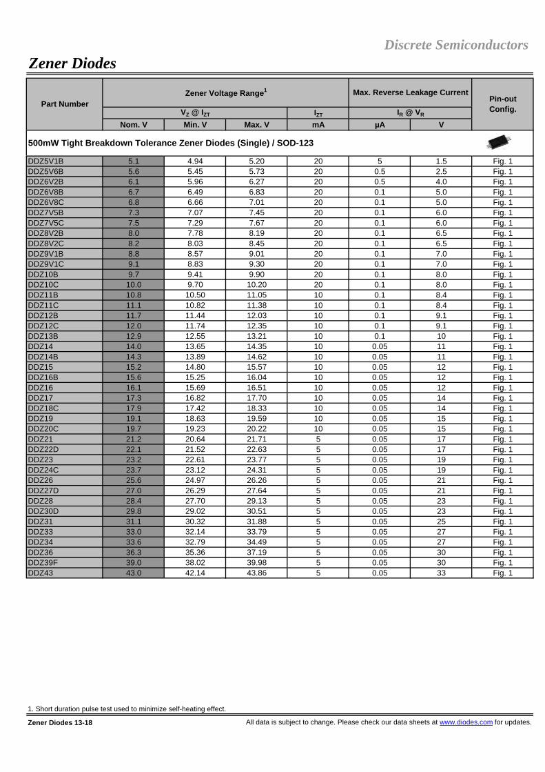
IZT
Nom. V Min. V Max. V mA µA V
DDZ5V1B 5.1 4.94 5.20 20 5 1.5 Fig. 1DDZ5V6B 5.6 5.45 5.73 20 0.5 2.5 Fig. 1DDZ6V2B 6.1 5.96 6.27 20 0.5 4.0 Fig. 1DDZ6V8B 6.7 6.49 6.83 20 0.1 5.0 Fig. 1DDZ6V8C 6.8 6.66 7.01 20 0.1 5.0 Fig. 1DDZ7V5B 7.3 7.07 7.45 20 0.1 6.0 Fig. 1DDZ7V5C 7.5 7.29 7.67 20 0.1 6.0 Fig. 1DDZ8V2B 8.0 7.78 8.19 20 0.1 6.5 Fig. 1DDZ8V2C 8.2 8.03 8.45 20 0.1 6.5 Fig. 1DDZ9V1B 8.8 8.57 9.01 20 0.1 7.0 Fig. 1DDZ9V1C 9.1 8.83 9.30 20 0.1 7.0 Fig. 1DDZ10B 9.7 9.41 9.90 20 0.1 8.0 Fig. 1DDZ10C 10.0 9.70 10.20 20 0.1 8.0 Fig. 1DDZ11B 10.8 10.50 11.05 10 0.1 8.4 Fig. 1DDZ11C 11.1 10.82 11.38 10 0.1 8.4 Fig. 1DDZ12B 11.7 11.44 12.03 10 0.1 9.1 Fig. 1DDZ12C 12.0 11.74 12.35 10 0.1 9.1 Fig. 1DDZ13B 12.9 12.55 13.21 10 0.1 10 Fig. 1DDZ14 14.0 13.65 14.35 10 0.05 11 Fig. 1DDZ14B 14.3 13.89 14.62 10 0.05 11 Fig. 1DDZ15 15.2 14.80 15.57 10 0.05 12 Fig. 1DDZ16B 15.6 15.25 16.04 10 0.05 12 Fig. 1DDZ16 16.1 15.69 16.51 10 0.05 12 Fig. 1DDZ17 17.3 16.82 17.70 10 0.05 14 Fig. 1DDZ18C 17.9 17.42 18.33 10 0.05 14 Fig. 1DDZ19 19.1 18.63 19.59 10 0.05 15 Fig. 1DDZ20C 19.7 19.23 20.22 10 0.05 15 Fig. 1DDZ21 21.2 20.64 21.71 5 0.05 17 Fig. 1DDZ22D 22.1 21.52 22.63 5 0.05 17 Fig. 1DDZ23 23.2 22.61 23.77 5 0.05 19 Fig. 1DDZ24C 23.7 23.12 24.31 5 0.05 19 Fig. 1DDZ26 25.6 24.97 26.26 5 0.05 21 Fig. 1DDZ27D 27.0 26.29 27.64 5 0.05 21 Fig. 1DDZ28 28.4 27.70 29.13 5 0.05 23 Fig. 1DDZ30D 29.8 29.02 30.51 5 0.05 23 Fig. 1DDZ31 31.1 30.32 31.88 5 0.05 25 Fig. 1DDZ33 33.0 32.14 33.79 5 0.05 27 Fig. 1DDZ34 33.6 32.79 34.49 5 0.05 27 Fig. 1DDZ36 36.3 35.36 37.19 5 0.05 30 Fig. 1DDZ39F 39.0 38.02 39.98 5 0.05 30 Fig. 1DDZ43 43.0 42.14 43.86 5 0.05 33 Fig. 1
1. Short duration pulse test used to minimize self-heating effect.
Zener Diodes 13-18 All data is subject to change. Please check our data sheets at www.diodes.com for updates.
Max. Reverse Leakage CurrentPin-outConfig.VZ @ IZT IR @ VR
500mW Tight Breakdown Tolerance Zener Diodes (Single) / SOD-123
Discrete SemiconductorsZener Diodes
Part NumberZener Voltage Range1

IZT
Nom. V Min. V Max. V mA µA V
DFLZ5V1 5.1 4.8 5.4 100 2.5 1 Fig. 1DFLZ5V6 5.6 5.2 6.0 100 10 2 Fig. 1DFLZ6V2 6.2 5.8 6.6 100 5 2 Fig. 1DFLZ6V8 6.8 6.4 7.2 100 5 3 Fig. 1DFLZ7V5 7.5 7.0 7.9 100 5 3 Fig. 1DFLZ8V2 8.2 7.7 8.7 100 5 3 Fig. 1DFLZ9V1 9.1 8.5 9.6 50 5 5 Fig. 1DFLZ10 10 9.4 10.6 50 5 7.5 Fig. 1DFLZ11 11 10.4 11.6 50 4 8.2 Fig. 1DFLZ12 12 11.4 12.7 50 3 9.1 Fig. 1DFLZ13 13 12.4 14.1 50 2 10 Fig. 1DFLZ15 15 13.8 15.6 50 1 11 Fig. 1DFLZ16 16 15.3 17.1 25 1 12 Fig. 1DFLZ18 18 16.8 19.1 25 1 13 Fig. 1DFLZ20 20 18.8 21.2 25 1 15 Fig. 1DFLZ22 22 20.8 23.3 25 1 16 Fig. 1DFLZ24 24 22.8 25.6 25 1 18 Fig. 1DFLZ27 27 25.1 28.9 25 1 20 Fig. 1DFLZ30 30 28.0 32.0 25 1 22 Fig. 1DFLZ33 33 31.0 35.0 25 1 24 Fig. 1DFLZ36 36 34.0 38.0 10 1 27 Fig. 1DFLZ39 39 37.0 41.0 10 1 30 Fig. 1
SMAZ5V1 5.1 4.84 5.40 100 2.5 1 Fig. 1SMAZ5V6 5.6 5.32 5.88 100 5 2 Fig. 1SMAZ6V2 6.2 5.89 6.51 100 5 3 Fig. 1SMAZ6V8 6.8 6.46 7.14 100 5 4 Fig. 1SMAZ7V5 7.5 7.13 7.88 100 5 5 Fig. 1SMAZ8V2 8.2 7.79 8.61 100 5 6 Fig. 1SMAZ9V1 9.1 8.65 9.56 50 5 7 Fig. 1SMAZ10 10 9.50 10.50 50 1 7.6 Fig. 1SMAZ12 12 11.40 12.60 50 1 9.1 Fig. 1SMAZ15 15 14.25 15.75 50 1 11.4 Fig. 1SMAZ16 16 15.20 16.80 25 0.5 12.2 Fig. 1SMAZ18 18 17.10 18.90 25 0.5 13.7 Fig. 1SMAZ20 20 19.00 21.00 25 0.5 15.2 Fig. 1SMAZ22 22 20.90 23.10 25 0.5 16.7 Fig. 1SMAZ24 24 22.80 25.20 25 0.5 18.2 Fig. 1SMAZ27 27 25.65 28.35 25 0.5 20.5 Fig. 1SMAZ30 30 28.50 31.50 25 0.5 22.8 Fig. 1SMAZ33 33 31.35 34.65 25 0.5 25.1 Fig. 1SMAZ36 36 34.20 37.80 10 0.5 27.4 Fig. 1SMAZ39 39 37.05 40.95 10 0.5 29.6 Fig. 1
1. Short duration pulse test used to minimize self-heating effect.
All data is subject to change. Please check our data sheets at www.diodes.com for updates. Zener Diodes 13-19
Part NumberZener Voltage Range1 Max. Reverse Leakage Current
Pin-outConfig.VZ @ IZT IR @ VR
Discrete SemiconductorsZener Diodes
1W Zener Diodes (Single) / SMA
1W Zener Diodes (Single) / PowerDI®123

Zener Diodes 13-20 All data is subject to change. Please check our data sheets at www.diodes.com for updates.
Figure 9Quad Common Anode SOT-363, SOT-563
Figure 8Triple Bi-directional SOT-363
Figure 10 DFN1006-2
Discrete SemiconductorsZener Diodes
Zener Diode Configurations
Figure 3Dual Common Anode SOT-23, SOT-323
Figure 1
Single PowerDI®323, PowerDI®123,SOD-123, SOD-323, SOD-523, SMA
Figure 6Dual Isolated (alt) SOT-363
Figure 4Dual Common Cathode SOT-23
Figure 5Dual Isolated SOT-363
Figure 7Triple Isolated SOT-363
Figure 2Single SOT-23, SOT-323, SOT-523

Reverse Standoff Voltage
Max. Reverse Leakage Current
VRWM IR @ VRWM
W µs V Min. (V) Max. (V) mA µA V A
TPD6V8LP 85 8x20 5 6.4 7.2 5 0.5 19 4.5 Fig. 7
T3V3S5 220 8x20 3.3 5.0 - 1 1 14.1 11.2 Fig. 5T5V0S5 260 8x20 5.0 6.2 - 1 0.05 22 9.4 Fig. 5T6V0S5 260 8x20 6.0 6.8 - 1 0.05 17 8.8 Fig. 5T12S5 300 8x20 12.0 14.1 - 1 0.01 25 9.6 Fig. 5
MMBZ5V6AL 24 10x1000 3 5.32 5.88 20 5 8 3 Fig. 1MMBZ6V2AL 24 10x1000 3 5.89 6.51 1 0.5 8.7 2.76 Fig. 1MMBZ6V8AL 24 10x1000 4.5 6.46 7.14 1 0.5 9.6 2.5 Fig. 1MMBZ9V1AL 24 10x1000 6 8.65 9.56 1 0.3 14 1.7 Fig. 1MMBZ10VAL 24 10x1000 6.5 9.5 10.5 1 0.3 14.2 1.7 Fig. 1
MMBZ15VAL 40 10x1000 12 14.25 15.75 1 0.05 21 1.9 Fig. 1MMBZ18VAL 40 10x1000 14.5 17.1 18.9 1 0.05 25 1.6 Fig. 1MMBZ20VAL 40 10x1000 17 19 21 1 0.05 28 1.4 Fig. 1MMBZ27VAL 40 10x1000 22 25.65 28.35 1 0.05 40 1 Fig. 1MMBZ33VAL 40 10x1000 26 31.35 34.65 1 0.05 46 0.87 Fig. 1
MMBZ15VDL 40 10x1000 12.8 14.3 15.8 1 0.1 21.2 1.9 Fig. 2MMBZ27VCL 40 10x1000 22 25.65 28.35 1 0.05 38 1 Fig. 2
DLP03LC 350 8x20 3.3 4 - 1 110 18 20 Fig. 3DLP05LC 300 8x20 5 6 - 1 20 11 1 Fig. 3DLPT05 300 8x20 5 6 - 1 20 9.8 1 Fig. 4
DLP3V3DTZ 372 8x20 3.3 4.5 - 1 95 9.3 40 Fig. 1
DLPD3V3LC 330 8x20 3.3 4 - 1 110 22 15 Fig. 8
(†) Reference product data sheet for specific conditions.
All data is subject to change. Please check our data sheets at www.diodes.com for updates. Transient Voltage Suppressors (TVS) 14-1
Transient Voltage Suppressors (TVS)Discrete Semiconductors
Transient Voltage Suppressors / DFN1006-2
Pin-Out Config.Part Number
VBR @ IT VC @ IPP
Transient Voltage Suppressors / SOD-523
Power Rating
Waveform for Power Rating (†)
Breakdown Voltage MaximumClampingVoltage (†)
24W Peak Power Transient Voltage Suppressors (Common Anode) / SOT-23
40W Peak Power Transient Voltage Suppressors (Common Anode) / SOT-23
40W Peak Power Transient Voltage Suppressors (Common Cathode) / SOT-23
Transient Voltage Suppressors (Bi-directional) / SOT-23
Low Capacitance Transient Voltage Suppressors (Uni-directional) / SOT-23
Low Capacitance Transient Voltage Suppressors (Bi-directional) / SOT-26

Reverse Standoff Voltage
Max. Reverse Leakage Current
VRWM IR @ VRWM
W µs V Min. (V) Max. (V) mA µA V A
DFLT5V0A 225 10x1000 5 6.4 7.0 10 400 9.2 24.5 Fig. 5DFLT6V0A 225 10x1000 6 6.67 7.37 10 400 10.3 21.8 Fig. 5DFLT6V5A 225 10x1000 6.5 7.22 7.98 10 250 11.2 20.1 Fig. 5DFLT7V0A 225 10x1000 7 7.78 8.60 10 100 12.0 18.8 Fig. 5DFLT7V5A 225 10x1000 7.5 8.33 9.21 1 50 12.9 17.4 Fig. 5DFLT8V0A 225 10x1000 8 8.89 9.83 1 25 13.6 16.5 Fig. 5DFLT8V5A 225 10x1000 8.5 9.44 10.40 1 10 14.4 15.6 Fig. 5DFLT9V0A 225 10x1000 9 10.0 11.1 1 5 15.4 14.6 Fig. 5DFLT10A 225 10x1000 10 11.1 12.3 1 2.5 17.0 13.2 Fig. 5DFLT11A 225 10x1000 11 12.2 13.5 1 2.5 18.2 12.4 Fig. 5DFLT12A 225 10x1000 12 13.3 14.7 1 2.5 19.9 11.3 Fig. 5DFLT13A 225 10x1000 13 14.4 15.9 1 1 21.5 10.5 Fig. 5DFLT14A 225 10x1000 14 15.6 17.2 1 1 23.2 9.7 Fig. 5DFLT15A 225 10x1000 15 16.7 18.5 1 1 24.4 9.22 Fig. 5DFLT16A 225 10x1000 16 17.8 19.7 1 1 26.0 8.65 Fig. 5DFLT17A 225 10x1000 17 18.9 20.9 1 1 27.6 8.15 Fig. 5DFLT18A 225 10x1000 18 20.0 22.1 1 1 29.2 7.71 Fig. 5DFLT20A 225 10x1000 20 22.2 24.5 1 1 32.4 6.94 Fig. 5DFLT22A 225 10x1000 22 24.4 26.9 1 1 35.5 6.34 Fig. 5DFLT24A 225 10x1000 24 26.7 29.5 1 1 38.9 5.78 Fig. 5DFLT26A 225 10x1000 26 28.9 31.9 1 1 42.1 5.35 Fig. 5DFLT27A 225 10x1000 27 30.0 33.15 1 1 43.7 5.15 Fig. 5DFLT28A 225 10x1000 28 31.1 34.4 1 1 45.4 4.96 Fig. 5DFLT30A 225 10x1000 30 33.3 36.8 1 1 48.4 4.65 Fig. 5DFLT33A 225 10x1000 33 36.7 40.6 1 1 53.3 4.22 Fig. 5DFLT36A 225 10x1000 36 40.0 44.2 1 1 58.1 3.87 Fig. 5DFLT40A 225 10x1000 40 44.4 49.1 1 1 64.5 3.49 Fig. 5DFLT43A 225 10x1000 43 47.8 52.8 1 1 69.4 3.24 Fig. 5DFLT45A 225 10x1000 45 50.0 55.3 1 1 72.7 3.10 Fig. 5DFLT48A 225 10x1000 48 53.3 58.9 1 1 77.4 2.91 Fig. 5DFLT51A 225 10x1000 51 56.7 62.7 1 1 82.4 2.73 Fig. 5
SMAJ5.0(C)A 400 10x1000 5 6.40 7.25 10 1600 9.2 43.5 Fig. 5/6SMAJ6.0(C)A 400 10x1000 6 6.67 7.37 10 1600 10.3 38.8 Fig. 5/6SMAJ6.5(C)A 400 10x1000 6.5 7.22 7.98 10 1000 11.2 35.7 Fig. 5/6SMAJ7.0(C)A 400 10x1000 7 7.78 8.6 10 400 12.0 33.3 Fig. 5/6SMAJ7.5(C)A 400 10x1000 7.5 8.33 9.21 1 200 12.9 31.0 Fig. 5/6SMAJ8.0(C)A 400 10x1000 8 8.89 9.83 1 100 13.6 29.4 Fig. 5/6SMAJ8.5(C)A 400 10x1000 8.5 9.44 10.4 1 20 14.4 27.7 Fig. 5/6SMAJ9.0(C)A 400 10x1000 9 10.0 11.1 1 10 15.4 26.0 Fig. 5/6SMAJ10(C)A 400 10x1000 10 11.1 12.3 1 10 17.0 23.5 Fig. 5/6SMAJ11(C)A 400 10x1000 11 12.2 13.5 1 5 18.2 22.0 Fig. 5/6SMAJ12(C)A 400 10x1000 12 13.3 14.7 1 5 19.9 20.1 Fig. 5/6SMAJ13(C)A 400 10x1000 13 14.4 15.9 1 5 21.5 18.6 Fig. 5/6SMAJ14(C)A 400 10x1000 14 15.6 17.2 1 5 23.2 17.2 Fig. 5/6SMAJ15(C)A 400 10x1000 15 16.7 18.5 1 5 24.4 16.4 Fig. 5/6SMAJ16(C)A 400 10x1000 16 17.8 19.7 1 5 26.0 15.3 Fig. 5/6
(†) Reference product data sheet for specific conditions.
Transient Voltage Suppressors (TVS) 14-2 All data is subject to change. Please check our data sheets at www.diodes.com for updates.
Breakdown Voltage MaximumClampingVoltage (†) Pin-Out
Config.VBR @ IT VC @ IPP
225W Transient Voltage Suppressors / PowerDI®123
400W Transient Voltage Suppressors / SMA
Discrete SemiconductorsTransient Voltage Suppressors (TVS)
Part NumberPower Rating
Waveform for Power Rating (†)

Reverse Standoff Voltage
Max. Reverse Leakage Current
VRWM IR @ VRWM
W µs V Min. (V) Max. (V) mA µA V A
SMAJ17(C)A 400 10x1000 17 18.9 20.9 1 5 27.6 14.5 Fig. 5/6SMAJ18(C)A 400 10x1000 18 20.0 22.1 1 5 29.2 13.7 Fig. 5/6SMAJ20(C)A 400 10x1000 20 22.2 24.5 1 5 32.4 12.3 Fig. 5/6SMAJ22(C)A 400 10x1000 22 24.4 26.9 1 5 35.5 11.2 Fig. 5/6SMAJ24(C)A 400 10x1000 24 26.7 29.5 1 5 38.9 10.3 Fig. 5/6SMAJ26(C)A 400 10x1000 26 28.9 31.9 1 5 42.1 9.5 Fig. 5/6SMAJ28(C)A 400 10x1000 28 31.1 34.4 1 5 45.4 8.8 Fig. 5/6SMAJ30(C)A 400 10x1000 30 33.3 36.8 1 5 48.4 8.3 Fig. 5/6SMAJ33(C)A 400 10x1000 33 36.7 40.6 1 5 53.3 7.5 Fig. 5/6SMAJ36(C)A 400 10x1000 36 40.0 44.2 1 5 58.1 6.9 Fig. 5/6SMAJ40(C)A 400 10x1000 40 44.4 49.1 1 5 64.5 6.2 Fig. 5/6SMAJ43(C)A 400 10x1000 43 47.8 52.8 1 5 69.4 5.7 Fig. 5/6SMAJ45(C)A 400 10x1000 45 50.0 55.3 1 5 72.7 5.5 Fig. 5/6SMAJ48(C)A 400 10x1000 48 53.3 58.9 1 5 77.4 5.2 Fig. 5/6SMAJ51(C)A 400 10x1000 51 56.7 62.7 1 5 82.4 4.9 Fig. 5/6SMAJ54(C)A 400 10x1000 54 60.0 66.3 1 5 87.1 4.6 Fig. 5/6SMAJ58(C)A 400 10x1000 58 64.4 71.2 1 5 93.6 4.3 Fig. 5/6SMAJ60(C)A 400 10x1000 60 66.7 73.7 1 5 96.8 4.1 Fig. 5/6SMAJ64(C)A 400 10x1000 64 71.1 78.6 1 5 103 3.9 Fig. 5/6SMAJ70(C)A 400 10x1000 70 77.8 86 1 5 113 3.5 Fig. 5/6SMAT70A 400 10x1000 70 77.8 89.5 1 5 100 3.5 Fig. 5SMAJ75(C)A 400 10x1000 75 83.3 92.1 1 5 121 3.3 Fig. 5/6SMAJ78(C)A 400 10x1000 78 86.7 95.8 1 5 126 2.2 Fig. 5/6SMAJ85(C)A 400 10x1000 85 94.4 104 1 5 137 2.9 Fig. 5/6SMAJ90(C)A 400 10x1000 90 100 111 1 5 146 2.7 Fig. 5/6SMAJ100(C)A 400 10x1000 100 111 123 1 5 162 2.5 Fig. 5/6SMAJ110(C)A 400 10x1000 110 122 135 1 5 177 2.3 Fig. 5/6SMAJ120(C)A 400 10x1000 120 133 147 1 5 193 2 Fig. 5/6SMAJ130(C)A 400 10x1000 130 144 159 1 5 209 1.9 Fig. 5/6SMAJ150(C)A 400 10x1000 150 167 185 1 5 243 1.6 Fig. 5/6SMAJ160(C)A 400 10x1000 160 178 197 1 5 259 1.5 Fig. 5/6SMAJ170(C)A 400 10x1000 170 189 209 1 5 275 1.4 Fig. 5/6
SMBJ5.0(C)A 600 10x1000 5 6.4 7.23 10 1600 9.2 65.2 Fig. 5/6SMBJ6.0(C)A 600 10x1000 6 6.67 7.67 10 1600 10.3 58.3 Fig. 5/6SMBJ6.5(C)A 600 10x1000 6.5 7.22 8.3 10 1000 11.2 53.6 Fig. 5/6SMBJ7.0(C)A 600 10x1000 7 7.78 8.95 10 400 12 50 Fig. 5/6SMBJ7.5(C)A 600 10x1000 7.5 8.33 9.58 1 200 12.9 46.5 Fig. 5/6SMBJ8.0(C)A 600 10x1000 8 8.89 10.23 1 100 13.6 44.1 Fig. 5/6SMBJ8.5(C)A 600 10x1000 8.5 9.44 10.82 1 20 14.4 41.7 Fig. 5/6SMBJ9.0(C)A 600 10x1000 9 10 11.5 1 10 15.4 39 Fig. 5/6SMBJ10(C)A 600 10x1000 10 11.1 12.8 1 10 17 35.3 Fig. 5/6SMBJ11(C)A 600 10x1000 11 12.2 14.4 1 5 18.2 33 Fig. 5/6
(†) Reference product data sheet for specific conditions.
All data is subject to change. Please check our data sheets at www.diodes.com for updates. Transient Voltage Suppressors (TVS) 14-3
VC @ IPP
400W Transient Voltage Suppressors / SMA (continued)
600W Transient Voltage Suppressors / SMB
Discrete SemiconductorsTransient Voltage Suppressors (TVS)
Part NumberPower Rating
Waveform for Power Rating (†)
Breakdown Voltage MaximumClampingVoltage (†) Pin-Out
Config.VBR @ IT

Reverse Standoff Voltage
Max. Reverse Leakage Current
VRWM IR @ VRWM
W µs V Min. (V) Max. (V) mA µA V A
SMBJ12(C)A 600 10x1000 12 13.3 15.3 1 5 19.9 30.2 Fig. 5/6SMBJ13(C)A 600 10x1000 13 14.4 16.5 1 5 21.5 27.9 Fig. 5/6SMBJ14(C)A 600 10x1000 14 15.6 17.9 1 5 23.2 25.8 Fig. 5/6SMBJ15(C)A 600 10x1000 15 16.7 19.2 1 5 24.4 24.0 Fig. 5/6SMBJ16(C)A 600 10x1000 16 17.8 20.5 1 5 26.0 23.1 Fig. 5/6SMBJ17(C)A 600 10x1000 17 18.9 21.7 1 5 27.6 21.7 Fig. 5/6SMBJ18(C)A 600 10x1000 18 20.0 23.3 1 5 29.2 20.5 Fig. 5/6SMBJ20(C)A 600 10x1000 20 22.2 25.5 1 5 32.4 18.5 Fig. 5/6SMBJ22(C)A 600 10x1000 22 24.4 28.0 1 5 35.5 16.9 Fig. 5/6SMBJ24(C)A 600 10x1000 24 26.7 30.7 1 5 38.9 15.4 Fig. 5/6SMBJ26(C)A 600 10x1000 26 28.9 33.2 1 5 42.1 14.2 Fig. 5/6SMBJ28(C)A 600 10x1000 28 31.1 35.8 1 5 45.4 13.2 Fig. 5/6SMBJ30(C)A 600 10x1000 30 33.3 38.3 1 5 48.4 12.4 Fig. 5/6SMBJ33(C)A 600 10x1000 33 36.7 42.2 1 5 53.3 11.3 Fig. 5/6SMBJ36(C)A 600 10x1000 36 40.0 46.0 1 5 58.1 10.3 Fig. 5/6SMBJ40(C)A 600 10x1000 40 44.4 51.1 1 5 64.5 9.3 Fig. 5/6SMBJ43(C)A 600 10x1000 43 47.8 54.9 1 5 69.4 8.6 Fig. 5/6SMBJ45(C)A 600 10x1000 45 50 57.5 1 5 72.7 8.3 Fig. 5/6SMBJ48(C)A 600 10x1000 48 53.3 61.3 1 5 77.4 7.7 Fig. 5/6SMBJ51(C)A 600 10x1000 51 56.7 65.2 1 5 82.4 7.3 Fig. 5/6SMBJ54(C)A 600 10x1000 54 60.0 69.0 1 5 87.1 6.9 Fig. 5/6SMBJ58(C)A 600 10x1000 58 64.4 74.6 1 5 93.6 6.4 Fig. 5/6SMBJ60(C)A 600 10x1000 60 66.7 76.7 1 5 96.8 6.2 Fig. 5/6SMBJ64(C)A 600 10x1000 64 71.1 81.8 1 5 103 5.8 Fig. 5/6SMBJ70(C)A 600 10x1000 70 77.8 89.5 1 5 113 5.3 Fig. 5/6SMBT70A 600 10x1000 70 77.8 89.5 1 5 100 5.3 Fig. 5SMBJ75(C)A 600 10x1000 75 83.3 95.8 1 5 121 4.9 Fig. 5/6SMBJ78(C)A 600 10x1000 78 86.7 99.7 1 5 126 4.7 Fig. 5/6SMBJ85(C)A 600 10x1000 85 94.4 108.2 1 5 137 4.4 Fig. 5/6SMBJ90(C)A 600 10x1000 90 100 115.5 1 5 146 4.1 Fig. 5/6SMBJ100(C)A 600 10x1000 100 111 128 1 5 162 3.7 Fig. 5/6SMBJ110(C)A 600 10x1000 110 122 140 1 5 177 3.4 Fig. 5/6SMBJ120(C)A 600 10x1000 120 133 153 1 5 193 3.1 Fig. 5/6SMBJ130(C)A 600 10x1000 130 144 165.5 1 5 209 2.9 Fig. 5/6SMBJ150(C)A 600 10x1000 150 167 192.5 1 5 243 2.5 Fig. 5/6SMBJ160(C)A 600 10x1000 160 178 205 1 5 259 2.3 Fig. 5/6SMBJ170(C)A 600 10x1000 170 189 217.5 1 5 275 2.2 Fig. 5/6
(†) Reference product data sheet for specific conditions.
Transient Voltage Suppressors (TVS) 14-4 All data is subject to change. Please check our data sheets at www.diodes.com for updates.
MaximumClampingVoltage (†) Pin-Out
Config.VBR @ IT VC @ IPP
Part NumberPower Rating
Waveform for Power Rating (†)
Breakdown Voltage
Discrete SemiconductorsTransient Voltage Suppressors (TVS)
600W Transient Voltage Suppressors / SMB (continued)

Reverse Standoff Voltage
Max. Reverse Leakage Current
VRWM IR @ VRWM
W µs V Min. (V) Max. (V) mA µA V A
P6KE6V8(C)A 600 10x1000 5.8 6.45 7.14 10 2000 10.5 57 -P6KE7V5(C)A 600 10x1000 6.4 7.13 7.88 10 1000 11.3 53 -P6KE8V2(C)A 600 10x1000 7.02 7.79 8.61 10 400 12.1 50 -P6KE9V1(C)A 600 10x1000 7.78 8.65 9.55 1 100 13.4 45 -P6KE10(C)A 600 10x1000 8.55 9.5 10.5 1 20 14.5 41 -P6KE11(C)A 600 10x1000 9.4 10.5 11.6 1 5 15.6 38 -P6KE12(C)A 600 10x1000 10.2 11.4 12.6 1 5 16.7 36 -P6KE13(C)A 600 10x1000 11.1 12.4 13.7 1 5 18.2 33 -P6KE15(C)A 600 10x1000 12.8 14.3 15.8 1 5 21.2 28 -P6KE16(C)A 600 10x1000 13.6 15.2 16.8 1 5 22.5 27 -P6KE18(C)A 600 10x1000 15.3 17.1 18.9 1 5 25.2 24 -P6KE20(C)A 600 10x1000 17.1 19.0 21.0 1 5 27.7 22 -P6KE22(C)A 600 10x1000 18.8 20.9 23.1 1 5 30.6 20 -P6KE24(C)A 600 10x1000 20.5 22.8 25.2 1 5 33.2 18 -P6KE27(C)A 600 10x1000 23.1 25.7 28.4 1 5 37.5 16 -P6KE30(C)A 600 10x1000 25.6 28.5 31.5 1 5 41.4 14.4 -P6KE33(C)A 600 10x1000 28.2 31.4 34.7 1 5 45.7 13.2 -P6KE36(C)A 600 10x1000 30.8 34.2 37.8 1 5 49.9 12.0 -P6KE39(C)A 600 10x1000 33.3 37.1 41.0 1 5 53.9 11.2 -P6KE43(C)A 600 10x1000 36.8 40.9 45.2 1 5 59.3 10.1 -P6KE47(C)A 600 10x1000 40.2 44.7 49.4 1 5 64.8 9.3 -P6KE51(C)A 600 10x1000 43.6 48.5 53.6 1 5 70.1 8.6 -P6KE56(C)A 600 10x1000 47.8 53.2 58.8 1 5 77 7.8 -P6KE62(C)A 600 10x1000 53.0 58.9 65.1 1 5 85 7.1 -P6KE68(C)A 600 10x1000 58.1 64.6 71.4 1 5 92 6.5 -P6KE75(C)A 600 10x1000 64.1 71.3 78.8 1 5 103 5.8 -P6KE82(C)A 600 10x1000 70.1 77.9 86.1 1 5 113 5.3 -P6KE91(C)A 600 10x1000 77.8 86.5 95.5 1 5 125 4.8 -P6KE100(C)A 600 10x1000 85.5 95 105 1 5 137 4.4 -P6KE110(C)A 600 10x1000 94 105 116 1 5 152 4.0 -P6KE120(C)A 600 10x1000 102 114 126 1 5 165 3.6 -P6KE130(C)A 600 10x1000 111 124 137 1 5 179 3.3 -P6KE150(C)A 600 10x1000 128 143 158 1 5 207 2.9 -P6KE160(C)A 600 10x1000 136 152 168 1 5 219 2.7 -P6KE170(C)A 600 10x1000 145 162 179 1 5 234 2.6 -P6KE180(C)A 600 10x1000 154 171 189 1 5 246 2.4 -P6KE200(C)A 600 10x1000 171 190 210 1 5 274 2.2 -P6KE220(C)A 600 10x1000 185 209 231 1 5 328 1.83 -P6KE250(C)A 600 10x1000 214 237 263 1 5 344 1.75 -P6KE300(C)A 600 10x1000 256 285 315 1 5 414 1.45 -P6KE350(C)A 600 10x1000 300 332 368 1 5 482 1.25 -P6KE400(C)A 600 10x1000 342 380 420 1 5 548 1.1 -
(†) Reference product data sheet for specific conditions.
All data is subject to change. Please check our data sheets at www.diodes.com for updates. Transient Voltage Suppressors (TVS) 14-5
Discrete SemiconductorsTransient Voltage Suppressors (TVS)
Part NumberPower Rating
Waveform for Power Rating (†)
Breakdown Voltage MaximumClampingVoltage (†) Pin-Out
Config.VBR @ IT VC @ IPP
600W Transient Voltage Suppressors / DO-15

Reverse Standoff Voltage
Max. Reverse Leakage Current
VRWM IR @ VRWM
W µs V Min. (V) Max. (V) mA µA V A
SMCJ5.0(C)A 1500 10x1000 5 6.4 7.07 10 2000 9.2 163 Fig. 5/6SMCJ6.0(C)A 1500 10x1000 6 6.67 7.37 10 2000 10.3 146 Fig. 5/6SMCJ6.5(C)A 1500 10x1000 6.5 7.22 7.98 10 1000 11.2 134 Fig. 5/6SMCJ7.0(C)A 1500 10x1000 7 7.78 8.60 10 400 12.0 125 Fig. 5/6SMCJ7.5(C)A 1500 10x1000 7.5 8.33 9.21 1 200 12.9 116 Fig. 5/6SMCJ8.0(C)A 1500 10x1000 8 8.89 9.83 1 100 13.6 110 Fig. 5/6SMCJ8.5(C)A 1500 10x1000 8.5 9.44 10.4 1 40 14.4 104 Fig. 5/6SMCJ9.0(C)A 1500 10x1000 9 10.0 11.1 1 20 15.4 97.4 Fig. 5/6SMCJ10(C)A 1500 10x1000 10 11.1 12.3 1 10 17.0 88.2 Fig. 5/6SMCJ11(C)A 1500 10x1000 11 12.2 13.5 1 5 18.2 82.4 Fig. 5/6SMCJ12(C)A 1500 10x1000 12 13.3 14.7 1 5 19.9 75.3 Fig. 5/6SMCJ13(C)A 1500 10x1000 13 14.4 15.9 1 5 21.5 69.7 Fig. 5/6SMCJ14(C)A 1500 10x1000 14 15.6 17.2 1 5 23.2 64.7 Fig. 5/6SMCJ15(C)A 1500 10x1000 15 16.7 18.5 1 5 24.4 61.5 Fig. 5/6SMCJ16(C)A 1500 10x1000 16 17.8 19.7 1 5 26.0 57.7 Fig. 5/6SMCJ17(C)A 1500 10x1000 17 18.9 20.9 1 5 27.6 53.3 Fig. 5/6SMCJ18(C)A 1500 10x1000 18 20.0 22.1 1 5 29.2 51.4 Fig. 5/6SMCJ20(C)A 1500 10x1000 20 22.2 24.5 1 5 32.4 46.3 Fig. 5/6SMCJ22(C)A 1500 10x1000 22 24.4 27.0 1 5 35.5 42.2 Fig. 5/6SMCJ24(C)A 1500 10x1000 24 26.7 29.5 1 5 38.9 38.6 Fig. 5/6SMCJ26(C)A 1500 10x1000 26 28.9 31.9 1 5 42.1 35.6 Fig. 5/6SMCJ28(C)A 1500 10x1000 28 31.1 34.4 1 5 45.4 33.0 Fig. 5/6SMCJ30(C)A 1500 10x1000 30 33.3 36.8 1 5 48.4 31.0 Fig. 5/6SMCJ33(C)A 1500 10x1000 33 36.7 40.6 1 5 53.3 28.1 Fig. 5/6SMCJ36(C)A 1500 10x1000 36 40.0 44.2 1 5 58.1 25.8 Fig. 5/6SMCJ40(C)A 1500 10x1000 40 44.4 49.1 1 5 64.5 23.2 Fig. 5/6SMCJ43(C)A 1500 10x1000 43 47.8 52.8 1 5 69.4 21.6 Fig. 5/6SMCJ45(C)A 1500 10x1000 45 50.0 55.3 1 5 72.7 20.6 Fig. 5/6SMCJ48(C)A 1500 10x1000 48 53.3 58.9 1 5 77.4 19.4 Fig. 5/6SMCJ51(C)A 1500 10x1000 51 56.7 62.7 1 5 82.4 18.2 Fig. 5/6SMCJ54(C)A 1500 10x1000 54 60.0 66.3 1 5 87.1 17.2 Fig. 5/6SMCJ58(C)A 1500 10x1000 58 64.4 71.2 1 5 93.6 16.0 Fig. 5/6SMCJ60(C)A 1500 10x1000 60 66.7 73.7 1 5 96.8 15.5 Fig. 5/6SMCJ64(C)A 1500 10x1000 64 71.1 78.6 1 5 103 14.6 Fig. 5/6SMCJ70(C)A 1500 10x1000 70 77.8 86.0 1 5 113 13.3 Fig. 5/6SMCJ75(C)A 1500 10x1000 75 83.3 92.1 1 5 121 12.4 Fig. 5/6SMCJ78(C)A 1500 10x1000 78 86.7 95.8 1 5 126 11.4 Fig. 5/6SMCJ85(C)A 1500 10x1000 85 94.4 104 1 5 137 10.4 Fig. 5/6SMCJ90(C)A 1500 10x1000 90 100 111 1 5 146 10.3 Fig. 5/6SMCJ100(C)A 1500 10x1000 100 111 123 1 5 162 9.3 Fig. 5/6SMCJ110(C)A 1500 10x1000 110 122 135 1 5 177 8.4 Fig. 5/6SMCJ120(C)A 1500 10x1000 120 133 147 1 5 193 7.9 Fig. 5/6SMCJ130(C)A 1500 10x1000 130 144 159 1 5 209 7.2 Fig. 5/6SMCJ150(C)A 1500 10x1000 150 167 185 1 5 243 6.2 Fig. 5/6SMCJ160(C)A 1500 10x1000 160 178 197 1 5 259 5.8 Fig. 5/6SMCJ170(C)A 1500 10x1000 170 189 209 1 5 275 5.5 Fig. 5/6
(†) Reference product data sheet for specific conditions.
Transient Voltage Suppressors (TVS) 14-6 All data is subject to change. Please check our data sheets at www.diodes.com for updates.
Pin-Out Config.
VBR @ IT VC @ IPP
Discrete SemiconductorsTransient Voltage Suppressors (TVS)
1500W Transient Voltage Suppressors / SMC
Part NumberPower Rating
Waveform for Power Rating (†)
Breakdown Voltage MaximumClampingVoltage (†)

Reverse Standoff Voltage
Max. Reverse Leakage Current
VRWM IR @ VRWM
W µs V Min. (V) Max. (V) mA µA V A
1.5KE6V8(C)A 1500 10x1000 5.8 6.45 7.14 10 2000 10.5 143 -1.5KE7V5(C)A 1500 10x1000 6.4 7.13 7.88 10 1000 11.3 132 -1.5KE8V2(C)A 1500 10x1000 7.02 7.79 8.61 10 400 12.1 124 -1.5KE9V1(C)A 1500 10x1000 7.8 8.65 9.55 1 100 13.4 112 -1.5KE10(C)A 1500 10x1000 8.55 9.5 10.5 1 20 14.5 103 -1.5KE11(C)A 1500 10x1000 9.4 10.5 11.6 1 5 15.6 96 -1.5KE12(C)A 1500 10x1000 10.2 11.4 12.6 1 5 16.7 90 -1.5KE13(C)A 1500 10x1000 11.1 12.4 13.7 1 5 18.2 82 -1.5KE15(C)A 1500 10x1000 12.8 14.3 15.8 1 5 21.2 71 -1.5KE16(C)A 1500 10x1000 13.6 15.2 16.8 1 5 22.5 67 -1.5KE18(C)A 1500 10x1000 15.3 17.1 18.9 1 5 25.2 59.5 -1.5KE20(C)A 1500 10x1000 17.1 19.0 21.0 1 5 27.7 54 -1.5KE22(C)A 1500 10x1000 18.8 20.9 23.1 1 5 30.6 49 -1.5KE24(C)A 1500 10x1000 20.5 22.8 25.2 1 5 33.2 45 -1.5KE27(C)A 1500 10x1000 23.1 25.7 28.4 1 5 37.5 40 -1.5KE30(C)A 1500 10x1000 25.6 28.5 31.5 1 5 41.4 36 -1.5KE33(C)A 1500 10x1000 28.2 31.4 34.7 1 5 45.7 33 -1.5KE36(C)A 1500 10x1000 30.8 34.2 37.8 1 5 49.9 30 -1.5KE39(C)A 1500 10x1000 33.3 37.1 41.0 1 5 53.9 28 -1.5KE43(C)A 1500 10x1000 36.8 40.9 45.2 1 5 59.3 25.3 -1.5KE47(C)A 1500 10x1000 40.2 44.7 49.4 1 5 64.8 23.2 -1.5KE51(C)A 1500 10x1000 43.6 48.5 53.6 1 5 70.1 21.4 -1.5KE56(C)A 1500 10x1000 47.8 53.2 58.8 1 5 77 19.5 -1.5KE62(C)A 1500 10x1000 53.0 58.9 65.1 1 5 85 17.7 -1.5KE68(C)A 1500 10x1000 58.1 64.6 71.4 1 5 92 16.3 -1.5KE75(C)A 1500 10x1000 64.1 71.3 78.8 1 5 103 14.6 -1.5KE82(C)A 1500 10x1000 70.1 77.9 86.1 1 5 113 13.3 -1.5KE91(C)A 1500 10x1000 77.8 86.5 95.5 1 5 125 12 -1.5KE100(C)A 1500 10x1000 85.5 95 105 1 5 137 11 -1.5KE110(C)A 1500 10x1000 94 105 116 1 5 152 9.9 -1.5KE120(C)A 1500 10x1000 102 114 126 1 5 165 9.1 -1.5KE130(C)A 1500 10x1000 111 124 137 1 5 179 8.4 -1.5KE150(C)A 1500 10x1000 128 143 158 1 5 207 7.2 -1.5KE160(C)A 1500 10x1000 136 152 168 1 5 219 6.8 -1.5KE170(C)A 1500 10x1000 145 162 179 1 5 234 6.4 -1.5KE180(C)A 1500 10x1000 154 171 189 1 5 246 6.1 -1.5KE200(C)A 1500 10x1000 171 190 210 1 5 274 5.5 -1.5KE220(C)A 1500 10x1000 185 209 231 1 5 328 4.6 -1.5KE250(C)A 1500 10x1000 214 237 263 1 5 344 5 -1.5KE300(C)A 1500 10x1000 256 285 315 1 5 414 5 -1.5KE350(C)A 1500 10x1000 300 332 368 1 5 482 4 -1.5KE400(C)A 1500 10x1000 342 380 420 1 5 548 4 -
3.0SMCJ5.0A 3000 10x1000 5 6.4 7.07 10 1000 9.2 326.1 Fig. 53.0SMCJ20A 3000 10x1000 20 22.2 24.5 1 5 32.4 92.6 Fig. 53.0SMCJ22A 3000 10x1000 22 24.4 27.0 1 5 35.5 84.5 Fig. 53.0SMCJ24A 3000 10x1000 24 26.7 29.5 1 5 38.9 77.1 Fig. 53.0SMCJ28A 3000 10x1000 28 31.1 34.4 1 5 45.4 66.1 Fig. 53.0SMCJ30A 3000 10x1000 30 33.3 36.8 1 5 48.4 62.0 Fig. 53.0SMCJ58A 3000 10x1000 58 64.4 71.2 1 5 93.6 32.1 Fig. 5(†) Reference product data sheet for specific conditions.
All data is subject to change. Please check our data sheets at www.diodes.com for updates. Transient Voltage Suppressors (TVS) 14-7
Breakdown Voltage MaximumClampingVoltage (†) Pin-Out
Config.VBR @ IT VC @ IPP
Discrete SemiconductorsTransient Voltage Suppressors (TVS)
Part NumberPower Rating
Waveform for Power Rating (†)
1500W Transient Voltage Suppressors / DO-201
3000W Transient Voltage Suppressors / SMC
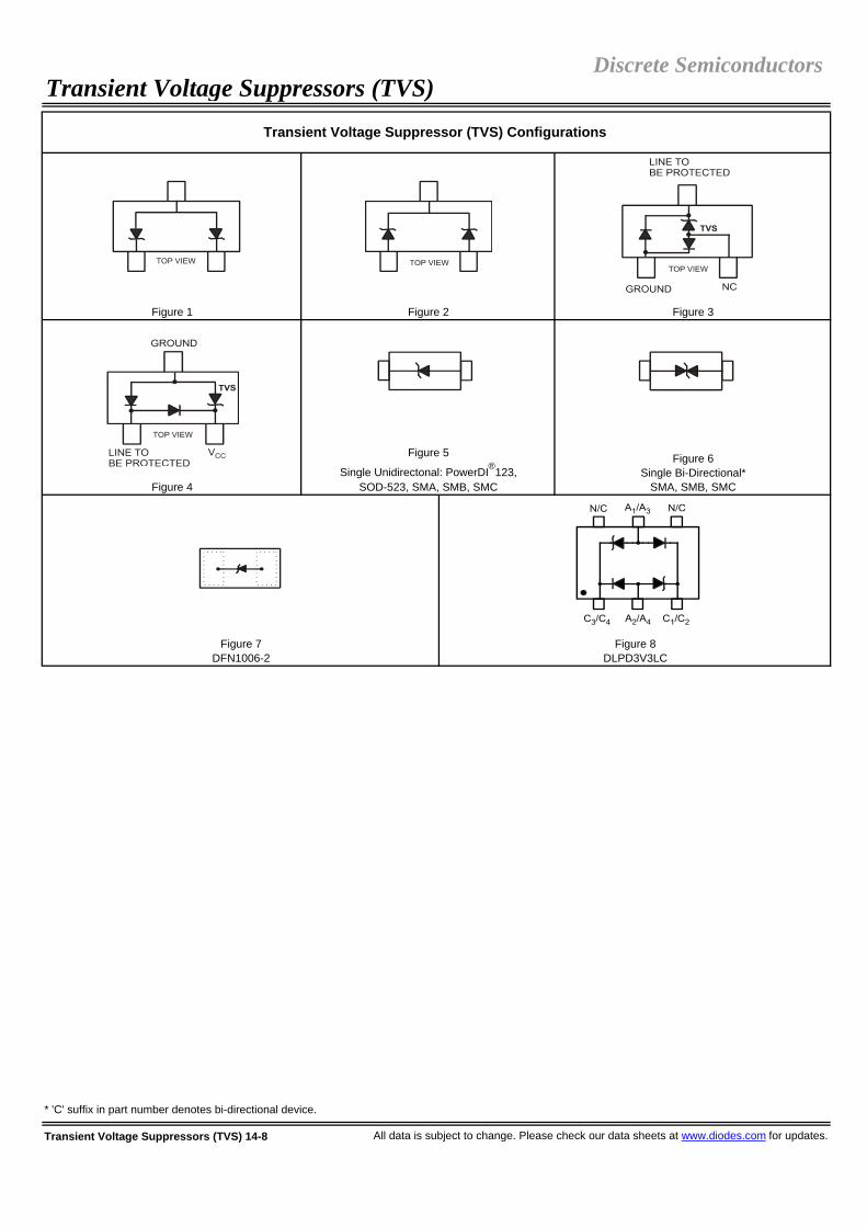
Transient Voltage Suppressors (TVS) 14-8 All data is subject to change. Please check our data sheets at www.diodes.com for updates.
Discrete SemiconductorsTransient Voltage Suppressors (TVS)
Transient Voltage Suppressor (TVS) Configurations
* 'C' suffix in part number denotes bi-directional device.
Figure 1 Figure 2 Figure 3
Figure 4
Figure 5
Single Unidirectonal: PowerDI®123, SOD-523, SMA, SMB, SMC
Figure 6Single Bi-Directional*
SMA, SMB, SMC
Figure 8DLPD3V3LC
Figure 7DFN1006-2

Rated Repetitive Off-State Voltage
Surge Rating
Off-State Leakage Current
Breakover Voltage
On-State Voltage
Off-State Capaci-tance
VDRM IPPIDRM @ VDRM
VBO VT @ IT = 1A CO
V A µA V V Min. (mA)
Max. (mA)
Min. (mA)
Max. (mA) pF
TB0640L 58 30 5 77 3.5 50 800 150 800 100TB0720L 65 30 5 88 3.5 50 800 150 800 100TB0900L 75 30 5 98 3.5 50 800 150 800 100TB1100L 90 30 5 130 3.5 50 800 150 800 60TB1300L 120 30 5 160 3.5 50 800 150 800 60TB1500L 140 30 5 180 3.5 50 800 150 800 60TB1800L 160 30 5 220 3.5 50 800 150 800 60TB2300L 190 30 5 265 3.5 50 800 150 800 40TB2600L 220 30 5 300 3.5 50 800 150 800 40TB3100L 275 30 5 350 3.5 50 800 150 800 40TB3500L 320 30 5 400 3.5 50 800 150 800 40
Waveformtr/tp
Standard Ipp (A)
2/10 µs GR-1089-CORE 2008/20 µs IEC 61000-4-5 150
10/160 µs FCC Part 68 10010/700 µs ITU-T, K20/21 6010/560 µs FCC Part 68 5010/1000 µs GR-1089-CORE 30
All data is subject to change. Please check our data sheets at www.diodes.com for updates. Thyristor Surge Protection Devices (TSPDs) 14-9
Thyristor Surge Protection Devices (TSPDs)Discrete Semiconductors
30A Bidirectional Thyristor Surge Protection Devices / SMB
Breakover Current
IBO
Holding Current
IHPart Number
Diodes Inc.’s surge protection device, TSPD, also known as a SIDAC, is offered in three surge rating series: 30A, 50A, and 100A. In the compact SMB package, the TSPD offers transient protection by switching to a low-voltage-on-state when the breakover voltage is reached in either direction.
TSPDs are breakover triggered crowbar protection devices that turn off when the surge current falls below the holding current value. TSPDs are designed to prevent damage to sensitive circuits from over voltage transients, and to meet various regulatory requirements such as GF1089-CORE, ITU-T-K20/21 and FCC Part 68.
TSPD V-I Characteristics

Rated Repetitive Off-State Voltage
Surge Rating
Off-State Leakage Current
Breakover Voltage
On-State Voltage
Off-State Capaci-tance
VDRM IPPIDRM @ VDRM
VBO VT @ IT = 1A CO
V A µA V V Min. (mA)
Max. (mA)
Min. (mA)
Max. (mA) pF
TB0640M 58 50 5 77 3.5 50 800 150 800 140TB0720M 65 50 5 88 3.5 50 800 150 800 140TB0900M 75 50 5 98 3.5 50 800 150 800 140TB1100M 90 50 5 130 3.5 50 800 150 800 90TB1300M 120 50 5 160 3.5 50 800 150 800 90TB1500M 140 50 5 180 3.5 50 800 150 800 90TB1800M 160 50 5 220 3.5 50 800 150 800 90TB2300M 190 50 5 265 3.5 50 800 150 800 60TB2600M 220 50 5 300 3.5 50 800 150 800 60TB3100M 275 50 5 350 3.5 50 800 150 800 60TB3500M 320 50 5 400 3.5 50 800 150 800 60
Waveformtr/tp
Standard Ipp (A)
2/10 µs GR-1089-CORE 3008/20 µs IEC 61000-4-5 250
10/160 µs FCC Part 68 15010/700 µs ITU-T, K20/21 10010/560 µs FCC Part 68 7510/1000 µs GR-1089-CORE 50
TB0640H 58 100 5 77 3.5 50 800 150 800 200TB0720H 65 100 5 88 3.5 50 800 150 800 200TB0900H 75 100 5 98 3.5 50 800 150 800 200TB1100H 90 100 5 130 3.5 50 800 150 800 120TB1300H 120 100 5 160 3.5 50 800 150 800 120TB1500H 140 100 5 180 3.5 50 800 150 800 120TB1800H 160 100 5 220 3.5 50 800 150 800 120TB2300H 190 100 5 265 3.5 50 800 150 800 80TB2600H 220 100 5 300 3.5 50 800 150 800 80TB3100H 275 100 5 350 3.5 50 800 150 800 80TB3500H 320 100 5 400 3.5 50 800 150 800 80
Waveformtr/tp
Standard Ipp (A)
2/10 µs GR-1089-CORE 5008/20 µs IEC 61000-4-5 400
10/160 µs FCC Part 68 25010/700 µs ITU-T, K20/21 20010/560 µs FCC Part 68 16010/1000 µs GR-1089-CORE 100
Thyristor Surge Protection Devices (TSPDs) 14-10 All data is subject to change. Please check our data sheets at www.diodes.com for updates.
Holding Current
50A Bidirectional Thyristor Surge Protection Devices / SMB
100A Bidirectional Thyristor Surge Protection Devices / SMB
IBO IH
Discrete SemiconductorsThyristor Surge Protection Devices (TSPDs)
Part Number
Breakover Current

All data is subject to change. Please check our data sheets at www.diodes.com for updates. Thyristor Surge Protection Devices (TSPDs) 14-11
Thyristor Surge Protection Device (TSPD) Configuration
Single Bi-directional / SMB
Discrete SemiconductorsThyristor Surge Protection Devices (TSPDs)

ReverseStand offVoltage
Power Rating
(8x20 µs wave-form)
Typical Capacitance
Between Data Line and Ground @ VR=0, f=1MHz
VRWM PPK CV W V mA µA V V A pF
DLPT05 5.0 300 6.0 1.0 20 5 9.8 1.0 1.9 1 Fig. 1SDA004 70 - 80 0.1 0.1 70 16 20 3.3 2 Fig. 2DLPA006 75 - 85 0.1 0.005 75 - - 2.7 3 Fig. 3SDA006 75 - 75 0.0025 2.5 75 16 14.5 11 3 Fig. 3QSBT40 25 - 30 0.1 2.0 25 - - 10 4 Fig. 4
DLP03LC 3.3 350 4.0 1.0 110 3.3 18 20 5 1 Fig. 5DLP05LC 5.0 300 6.0 1.0 20 5.0 11 1.0 1.6 1 Fig. 5
DLPD3V3LC 3.3 330 4.0 1.0 110 3.3 22 15 2.5 1 Fig. 6
Data Line Protection Devices 14-12 All data is subject to change. Please check our data sheets at www.diodes.com for updates.
Data Line Protection Devices
MinimumBreakdown
Voltage
MaximumLeakage Current
Maximum Clamping Voltage
Part Number
Discrete Semiconductors
Uni-Directional, Low Capacitance, Single Data Line Protection Devices with Integrated TVS / SOT-23
Bi-Directional, Low Capacitance, Single Data Line Protection Devices with Integrated TVS / SOT-26
Max. # of Data Lines
Protec-ted
Pin-Out Config.
Rail Clamps / SOT-363
VBR @ IT IR @ VR VC @ IPP
Data Line Protection Device Configurations
Figure 3
Figure 4 Figure 5 Figure 6
Figure 1 Figure 2

Collectorto Emitter Voltage
Max. Collector Current
VCEO ICmW V mA Min. Max. V / mA V mA mA MHz V mA
BC847BLP 250 45 100 200 450 5 / 2 0.25 10 0.5 100 5 10
BC857BLP 250 -45 -100 220 475 -5 / -2 -0.3 -10 -0.5 100 -5 -2
BC847CDLP 350 45 100 420 800 5 / 2 0.25 10 0.5 260 5 10
MMDT3946LP4 200 ±40 ±200 100 300 ±1 / ±10 0.20/-0.25 ±10 ±1 300/250 ±20 20/-10
MMBT3904T 150 40 200 100 300 1 / 10 0.2 10 1 300 20 10MMBT2222AT 150 40 600 100 300 10 / 150 0.3 150 15 300 20 20MMBT4401T 150 40 600 100 300 1 / 150 0.4 150 15 250 10 20BC847AT 150 45 100 110 220 5 / 2 0.25 10 0.5 100 5 10BC847BT 150 45 100 200 450 5 / 2 0.25 10 0.5 100 5 10BC847CT 150 45 100 420 800 5 / 2 0.25 10 0.5 100 5 102DC4617Q 150 50 150 120 270 6 / 1 0.4 50 5 180* 12 22DC4617R 150 50 150 180 390 6 / 1 0.4 50 5 180* 12 22DC4617S 150 50 150 270 560 6 / 1 0.4 50 5 180* 12 2
MMBT3906T 150 -40 -200 100 300 -1 / -10 -0.25 -10 -1 250 -20 -10MMBT4403T 150 -40 -600 100 300 -2 / -150 -0.4 -150 -15 200 -10 -20BC857AT 150 -45 -100 125 250 -5 / -2 -0.3 -10 -0.5 100 -5 -10BC857BT 150 -45 -100 220 475 -5 / -2 -0.3 -10 -0.5 100 -5 -10BC857CT 150 -45 -100 420 800 -5 / -2 -0.3 -10 -0.5 100 -5 -102DA1774Q 150 -50 -150 120 270 -6 / -1 -0.5 -50 -5 140* -12 -22DA1774R 150 -50 -150 180 390 -6 / -1 -0.5 -50 -5 140* -12 -22DA1774S 150 -50 -150 270 560 -6 / -1 -0.5 -50 -5 140* -12 -2MMBT2907AT 150 -60 -600 100 300 -10 / -150 -0.4 -150 -15 200 -20 -50
MMDT3904VC 150 40 200 100 300 1 / 10 0.2 10 1 300 20 10MMDT2222V 150 40 600 100 300 10 / 150 0.3 150 15 300 20 20BC847BVC 150 45 100 200 450 5 / 2 0.1 10 0.5 100 5 10
MMDT3906VC 150 -40 -200 100 300 -1 / -10 -0.4 -50 -5 250 -20 -10BC857BV 150 -45 -100 220 475 -5 / -2 -0.1 -10 -0.5 100 -5 -10MMDT2907V 150 -60 -600 100 300 -10 / -150 -0.4 -150 -15 200 -20 -50
BC847BVN 150 ±45 ±100 200/220 450/475 ±5 / ±2 0.25/-0.3 ±10 ±0.5 300/200 ±5 ±10
* Typical
All data is subject to change. Please check our data sheets at www.diodes.com for updates. Small Signal and Medium Power Bipolar Transistors 15-1
fT @ VCE / IC
PNP Transistors / SOT-523
Dual NPN Transistors / SOT-563
Dual PNP Transistors / SOT-563
Minimum Gain Bandwidth Product
NPN Transistors / DFN1006-3
Complementary NPN/PNP Transistors / DFN1310H4-6 (0.4mm Profile)
PNP Transistors / DFN1006-3
Dual NPN Transistors / DFN1310H4-6 (0.4mm Profile)
Part NumberVCE (SAT) @ IC / IB
DC Current Gain
hFE @ VCE / IC
Maximum Saturation Voltage,Collector to Emitter
Small Signal and Medium Power Bipolar TransistorsDiscrete Semiconductors
Power Rating
NPN Transistors / SOT-523
Complementary NPN/PNP Transistors / SOT-563

Collectorto Emitter Voltage
Max. Collector Current
VCEO ICmW V mA Min. Max. V / mA V mA mA MHz V mA
MMST4124 200 25 200 120 360 1 / 2 0.3 50 5 300 20 10BC848AW 200 30 100 110 220 5 / 2 0.25 10 0.5 300 5 10BC848BW 200 30 100 200 450 5 / 2 0.25 10 0.5 300 5 10BC848CW 200 30 100 420 800 5 / 2 0.25 10 0.5 300 5 10MMST2222A 200 40 600 100 300 10 / 150 0.3 150 15 300 20 20MMST3904 200 40 200 100 300 1 / 10 0.25 10 1 300 20 10MMST4401 200 40 600 100 300 1 / 150 0.4 150 15 250 10 20BC817-16W 200 45 500 100 250 1 / 100 0.7 500 50 100 5 10BC817-25W 200 45 500 160 400 1 / 100 0.7 500 50 100 5 10BC817-40W 200 45 500 250 600 1 / 100 0.7 500 50 100 5 10BC847AW 200 45 100 110 220 5 / 2 0.25 10 0.5 300 5 10BC847BW 200 45 100 200 450 5 / 2 0.25 10 0.5 300 5 10BC847CW 200 45 100 420 800 5 / 2 0.25 10 0.5 300 5 10MMSTA05 200 60 500 100 - 1 / 10 0.25 100 10 100 2 10BC846AW 200 65 100 110 220 5 / 2 0.25 10 0.5 300 5 10BC846BW 200 65 100 200 450 5 / 2 0.25 10 0.5 300 5 10MMSTA06 200 80 500 100 - 1 / 10 0.25 100 10 100 2 10MMST5551 200 160 200 80 250 5 / 10 0.15 10 1 300 10 10MMSTA42 200 300 200 40 - 10 / 10 0.5 20 2 50 20 10
MMST4126 200 -25 -200 120 360 -1 / -2 -0.4 -50 -5 250 -20 -10BC858AW 200 -30 -100 125 250 -5 / -2 -0.3 -10 -0.5 200 -5 -10BC858BW 200 -30 -100 220 475 -5 / -2 -0.3 -10 -0.5 200 -5 -10BC858CW 200 -30 -100 420 800 -5 / -2 -0.3 -10 -0.5 200 -5 -10MMST3906 200 -40 -200 100 300 -1 / -10 -0.2 -10 -1 300 -20 -10MMST4403 200 -40 -600 100 300 -2 / -150 -0.4 -150 -15 200 -10 -20BC807-16W 200 -45 -500 100 250 -1 / -100 -0.7 -500 -50 100 -5 -10BC807-25W 200 -45 -500 160 400 -1 / -100 -0.7 -500 -50 100 -5 -10BC807-40W 200 -45 -500 250 600 -1 / -100 -0.7 -500 -50 100 -5 -10BC857AW 200 -45 -100 125 250 -5 / -2 -0.3 -10 -0.5 200 -5 -10BC857BW 200 -45 -100 220 475 -5 / -2 -0.3 -10 -0.5 200 -5 -10BC857CW 200 -45 -100 420 800 -5 / -2 -0.3 -10 -0.5 200 -5 -10MMST2907A 200 -60 -600 100 300 -10 / -150 -0.4 -150 -15 200 -20 -50MMSTA55 200 -60 -500 100 - -1 / -100 -0.25 -100 -10 50 -1 -100BC856AW 200 -65 -100 125 250 -5 / -2 -0.3 -10 -0.5 200 -5 -10BC856BW 200 -65 -100 220 475 -5 / -2 -0.3 -10 -0.5 200 -5 -10MMSTA56 200 -80 -500 100 - -1 / -100 -0.25 -100 -10 50 -1 -100MMST5401 200 -150 -200 60 240 -5 / -10 -0.2 -10 -1 300 -10 -10MMSTA92 200 -300 -100 40 - -10 / -10 -0.5 -20 -2 50 -20 -10
MMDT4124 200 25 200 120 360 1 / 2 0.3 50 5 300 20 10MMDT2222A 200 40 600 100 300 10 / 150 0.3 150 15 300 20 20MMDT3904 200 40 200 100 300 1 / 10 0.2 10 1 300 20 10MMDT4401 200 40 600 100 300 1 / 150 0.4 150 15 250 10 20BC847BS 200 45 100 200 450 5 / 2 0.1 10 0.5 100 5 10BC846AS 200 65 100 110 220 5 / 2 0.25 10 0.5 175 5 10MMDT5551 200 160 200 80 250 5 / 10 0.15 10 1 300 10 10
Small Signal and Medium Power Bipolar Transistors 15-2 All data is subject to change. Please check our data sheets at www.diodes.com for updates.
NPN Transistors / SOT-323
Maximum Saturation Voltage,Collector to Emitter
Minimum Gain Bandwidth Product
hFE @ VCE / IC VCE (SAT) @ IC / IB fT @ VCE / IC
PNP Transistors / SOT-323
Dual NPN Transistors / SOT-363
Discrete SemiconductorsSmall Signal and Medium Power Bipolar Transistors
Part NumberPower Rating
DC Current Gain

Collectorto Emitter Voltage
Max. Collector Current
VCEO ICmW V mA Min. Max. V / mA V mA mA MHz V mA
MMDT4126 200 -25 -200 120 360 -1 / -2 -0.4 -50 -5 250 -20 -10MMDT3906 200 -40 -200 100 300 -1 / -10 -0.25 -10 -1 250 -20 -10MMDT4403 200 -40 -600 100 300 -2 / -150 -0.4 -150 -15 200 -10 -20BC857BS 200 -45 -100 220 475 -5 / -2 -0.1 -10 -0.5 100 -5 -10MMDT2907A 200 -60 -600 100 300 -10 / -150 -0.4 -150 -15 200 -20 -50BC856AS 200 -65 -100 125 250 -5 / -2 -0.3 -10 -0.5 350 -5 -10MMDT5401 200 -150 -200 60 240 -5 / -10 -0.2 -10 -1 300 -10 -10
MMDT4146 200 ±25 ±200 120 360 ±1 / ±2 0.3/-0.4 ±50 ±5 300/250 ±20 ±10MMDT3946 200 ±40 ±200 100 300 ±1 / ±10 0.20/-0.25 ±10 ±1 250 ±20 ±10MMDT4413 200 ±40 ±600 100 300 1/-2 / ±150 ±0.40 ±150 ±15 250/200 ±10 ±20BC847PN 200 ±45 ±100 200/220 450/475 ±5 / ±2 0.25/-0.3 ±10 ±0.5 300/200 ±5 ±10MMDT2227 200 +40/-60 ±600 100 300 ±10 / ±150 0.30/-0.40 ±150 ±15 300/200 ±20 ±20MMDT5451 200 ±150 ±200 80/60 250-240 ±5 / ±10 0.15/-0.2 ±10 ±1 300 ±10 ±10
MMBT123S 300 18 1000 150 800 1 / 100 0.5 300 30 100 10 50MMBT4124 300 25 200 120 360 1 / 2 0.3 50 5 300 20 10BC848A 300 30 100 110 220 5 / 2 0.25 10 0.5 300 5 10BC848B 300 30 100 200 450 5 / 2 0.25 10 0.5 300 5 10BC848C 300 30 100 420 800 5 / 2 0.25 10 0.5 300 5 10MMBT2222A 300 40 600 100 300 10 / 150 0.3 150 15 300 20 20MMBT3904 300 40 200 100 300 1 / 10 0.2 10 1 300 20 10MMBT4401 300 40 600 100 300 1 / 150 0.4 150 15 250 10 20BC817-16 310 45 800 100 250 1 / 100 0.7 500 50 100 5 10BC817-25 310 45 800 160 400 1 / 100 0.7 500 50 100 5 10BC817-40 310 45 800 250 600 1 / 100 0.7 500 50 100 5 10BC847A 300 45 100 110 220 5 / 2 0.25 10 0.5 300 5 10BC847B 300 45 100 200 450 5 / 2 0.25 10 0.5 300 5 10BC847C 300 45 100 420 800 5 / 2 0.25 10 0.5 300 5 10DNBT8105 300 60 1000 100 300 5 / 500 0.5 1000 100 150 10 50MMBTA05 300 60 500 100 - 1 / 10 0.25 100 10 100 2 10BC846A 300 65 100 110 220 5 / 2 0.25 10 0.5 300 5 10BC846B 300 65 100 200 450 5 / 2 0.25 10 0.5 200 5 10MMBTA06 300 80 500 100 - 1 / 10 0.25 100 10 100 2 10MMBT5551 300 160 200 80 250 5 / 10 0.15 10 1 300 10 10MMBTA42 300 300 500 40 - 10 / 10 0.5 20 2 50 20 10DN350T05 300 350 500 30 200 10 / 30 0.3 10 1 50 10 20
MMBTH10 300 25 50 60 - 10 / 4 0.5 4 0.4 650 10 4MMBTH24 300 40 50 30 - 10 / 8 0.5 4 0.4 400 10 8
All data is subject to change. Please check our data sheets at www.diodes.com for updates. Small Signal and Medium Power Bipolar Transistors 15-3
Dual PNP Transistors / SOT-363
Complementary NPN/PNP Transistors / SOT-363
DC Current GainMaximum
Saturation Voltage,Collector to Emitter
Minimum Gain Bandwidth Product
hFE @ VCE / IC VCE (SAT) @ IC / IB fT @ VCE / IC
Discrete SemiconductorsSmall Signal and Medium Power Bipolar Transistors
Part NumberPower Rating
UHF/VHF NPN Transistors / SOT-23
NPN Transistors / SOT-23

Collectorto Emitter Voltage
Max. Collector Current
VCEO ICmW V mA Min. Max. V / mA V mA mA MHz V mA
MMBT4126 300 -25 -200 120 360 -1 / -2 -0.4 -50 -5 250 -20 -10BC858A 300 -30 -100 125 250 -5 / -2 -0.3 -10 -0.5 200 -5 -10BC858B 300 -30 -100 220 475 -5 / -2 -0.3 -10 -0.5 200 -5 -10BC858C 300 -30 -100 420 800 -5 / -2 -0.3 -10 -0.5 200 -5 -10MMBT3906 300 -40 -200 100 300 -1 / -10 -0.25 -10 -1 250 -20 -10MMBT4403 300 -40 -600 100 300 -2 / -150 -0.4 -150 -15 200 -10 -20BC807-16 310 -45 -500 100 250 -1 / -100 -0.7 -500 -50 100 -5 -10BC807-25 310 -45 -500 160 400 -1 / -100 -0.7 -500 -50 100 -5 -10BC807-40 310 -45 -500 250 600 -1 / -100 -0.7 -500 -50 100 -5 -10BC857A 300 -45 -100 125 250 -5 / -2 -0.3 -10 -0.5 200 -5 -10BC857B 300 -45 -100 220 475 -5 / -2 -0.3 -10 -0.5 200 -5 -10BC857C 300 -45 -100 420 800 -5 / -2 -0.3 -10 -0.5 200 -5 -10DPBT8105 300 -60 -1000 100 300 -5 / -500 -0.6 -1000 -100 150 -10 -50MMBT2907A 300 -60 -600 100 300 -10 / -150 -0.4 -150 -15 200 -20 -50MMBTA55 300 -60 -500 100 - -1 / -100 -0.25 -100 -10 50 -1 -100BC856A 300 -65 -100 125 250 -5 / -2 -0.3 -10 -0.5 200 -5 -10BC856B 300 -65 -100 220 475 -5 / -2 -0.3 -10 -0.5 200 -5 -10MMBTA56 300 -80 -500 100 - -1 / -100 -0.25 -100 -10 50 -1 -100MMBT5401 300 -150 -200 60 240 -5 / -10 -0.2 -10 -1 300 -10 -10MMBTA92 300 -300 -500 40 - -10 / -10 -0.5 -20 -2 50 -20 -10DP350T05 300 -350 -500 30 200 -10 / -30 -0.3 -10 -1 50 -10 -20
IMX8 300 120 50 180 820 6 / 2 0.5 10 1 140* 12 2MMDTA42 300 300 500 40 - 10 / 10 0.5 20 2 50 20 10
IMT4 225 -120 -50 180 820 -6 / -2 -0.5 -10 -1 140* -12 -2
MMDT2227M 300 40/-60 ±600 100 300 ±10 / ±150 0.30/-0.40 ±150 ±15 300/200 ±20 ±20
LBN150B01 300 ±40 ±150 90/70 -/- ±1 / ±50 0.15/-0.16 ±50 ±5 250 ±20 ±10
DCX68 1000 20 1000 85 375 1 / 500 0.5 1000 100 330* 5 100DXT3150 1000 25 5000 250 550 2 / 500 0.5 4000 200 150* 6 50DXT3904 1000 40 200 100 300 1 / 10 0.2 10 1 300 20 10DXT2222A 1000 40 600 100 300 10 / 150 0.3 150 15 300 20 202DD1664R 1000 40 1000 180 390 3 / 100 0.4 500 50 280* 5 502DD1766Q 1000 40 2000 120 270 3 / 500 0.8 2000 200 220* 5 50DCX54 1000 45 1000 63 250 2 / 150 0.5 500 50 200* 5 50DCX55 1000 60 1000 63 250 2 / 150 0.5 500 50 200* 5 50DCX56 1000 80 1000 63 250 2 / 150 0.5 500 50 200* 5 50DXTA42 1000 300 500 40 - 10 / 10 0.5 20 2 50 20 10
* Typical
Small Signal and Medium Power Bipolar Transistors 15-4 All data is subject to change. Please check our data sheets at www.diodes.com for updates.
PNP Transistors / SOT-23
Dual PNP Transistors / SOT-26
Dual NPN Transistors / SOT-26
Discrete SemiconductorsSmall Signal and Medium Power Bipolar Transistors
Part NumberPower Rating
DC Current GainMaximum
Saturation Voltage,Collector to Emitter
Medium Power NPN Transistors / SOT89-3L
Complex Dual NPN/PNP Transistors / SOT-26
Complementary NPN/PNP Transistors / SOT-26
Minimum Gain Bandwidth Product
hFE @ VCE / IC VCE (SAT) @ IC / IB fT @ VCE / IC

Collectorto Emitter Voltage
Max. Collector Current
VCEO ICmW V mA Min. Max. V / mA V mA mA MHz V mA
DCX69A 1000 -20 -1000 85 375 -1 / -500 -0.5 -1000 -100 250* -5 -1002DB1386Q 1000 -30 -5000 120 270 -2 / -500 -1 -4000 -100 55* -6 -50DXT3906 1000 -40 -200 100 300 -1 / -10 -0.25 -10 -1 250 -20 -102DB1132R 1000 -40 -1000 180 390 -3 / -100 -0.5 -500 -50 190* -5 -502DB1188Q 1000 -40 -2000 120 270 -3 / -500 -0.8 -2000 -200 120* -5 -500DCX51 1000 -45 -1000 63 250 -2 / -150 -0.5 -500 -50 200* -5 -50DXT2907A 1000 -60 -600 100 300 -10 / -150 -0.4 -150 -15 200 -20 -50DCX52 1000 -60 -1000 63 250 -2 / -150 -0.5 -500 -50 200* -5 -50DCX53 1000 -80 -1000 63 250 -2 / -150 -0.5 -500 -50 200* -5 -50DXTA92 1000 -300 -500 40 - -10 / -10 -0.5 -20 -2 50 -20 -10
DCP68 1000 20 1000 85 375 1 / 500 0.5 1000 100 330* 5 100DZT3150 1000 25 5000 250 550 2 / 500 0.5 4000 200 150* 6 50DZT2222A 1000 40 600 100 300 10 / 150 0.3 150 15 300 20 20DCP54 1000 45 1000 63 250 2 / 150 0.5 500 50 200* 5 50DCP54-16 1000 45 1000 100 250 2 / 150 0.5 500 50 200* 5 50DCP55 1000 60 1000 40 250 2 / 150 0.5 500 50 200* 5 50DCP55-16 1000 60 1000 100 250 2 / 150 0.5 500 50 200* 5 50DZT491 1000 60 1000 100 300 5 / 500 0.25 500 50 150 10 50DZT851 1000 60 6000 100 300 1 / 2000 0.375 6000 300 130* 10 100DCP56 1000 80 1000 40 250 2 / 150 0.5 500 50 200* 5 50DCP56-16 1000 80 1000 100 250 2 / 150 0.5 500 50 200* 5 50DZT853 1000 100 6000 100 300 2 / 2000 0.34 5000 500 130* 10 100DZTA42 1000 300 500 40 - 10 / 10 0.5 20 2 50 20 10
DCP69A 1000 -20 -1000 85 375 -1 / -500 -0.5 -1000 -100 250* -5 -100DCP69A-16 1000 -20 -1000 100 250 -1 / -500 -0.5 -1000 -100 250* -5 -100DCP51 1000 -45 -1000 40 250 -2 / -150 -0.5 -500 -50 200* -5 -50DCP51-16 1000 -45 -1000 100 250 -2 / -150 -0.5 -500 -50 200* -5 -50DCP52 1000 -60 -1000 40 250 -2 / -150 -0.5 -500 -50 200* -5 -50DCP52-16 1000 -60 -1000 100 250 -2 / -150 -0.5 -500 -50 200* -5 -50DZT2907A 1000 -60 -600 100 300 -10 / -150 -0.4 -150 -15 200 -20 -50DZT591C 1000 -60 -1000 100 300 -5 / -500 -0.3 -500 -50 150 -10 -50DZT951 1000 -60 -5000 100 300 1 / -2000 -0.46 -5000 -500 120* -10 -100DCP53 1000 -80 -1000 40 250 -2 / -150 -0.5 -500 -50 200* -5 -50DCP53-16 1000 -80 -1000 100 250 -2 / -150 -0.5 -500 -50 200* -5 -50DZT953 1000 -100 -5000 100 300 1 / -1000 -0.42 -4000 -400 125* -10 -100DZTA92 1000 -300 -500 40 - -10 / -10 -0.5 -20 -2 50 -20 -10
* Typical
All data is subject to change. Please check our data sheets at www.diodes.com for updates. Small Signal and Medium Power Bipolar Transistors 15-5
Medium Power PNP Transistors / SOT89-3L
Discrete SemiconductorsSmall Signal and Medium Power Bipolar Transistors
Part NumberPower Rating
DC Current Gain
Medium Power NPN Transistors / SOT-223
Medium Power PNP Transistors / SOT-223
Maximum Saturation Voltage,Collector to Emitter
Minimum Gain Bandwidth Product
hFE @ VCE / IC VCE (SAT) @ IC / IB fT @ VCE / IC

Small Signal and Medium Power Bipolar Transistors 15-6 All data is subject to change. Please check our data sheets at www.diodes.com for updates.
Discrete SemiconductorsSmall Signal and Medium Power Bipolar Transistors
Dual Complementary SOT-563, SOT-363, SOT-26 LBN150B01
NPN, PNP Transistor Device Configurations
NPNDFN1006-3
PNP DFN1006-3
Dual NPN DFN1310H4-6
Single SOT-523, SOT-323, SOT-23
NPN SOT89-3L, SOT-223
PNPSOT89-3L, SOT-223
IMX8 IMT4
Dual Complementary DFN1310H4-6
Dual NPNSOT-563, SOT-363, SOT-26
Dual PNPSOT-563, SOT-363
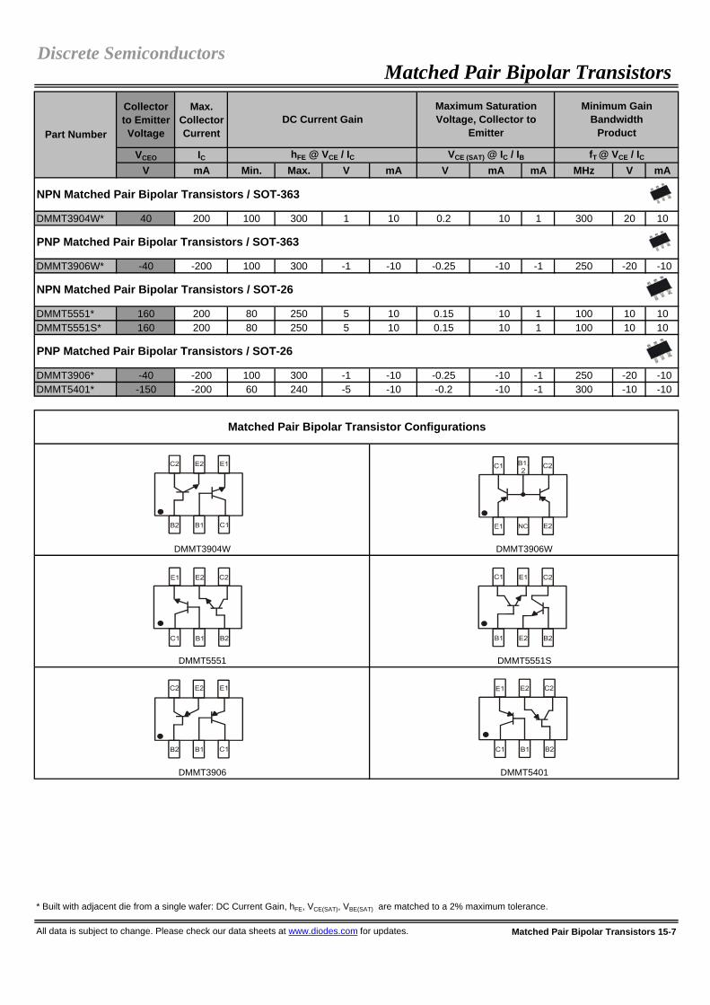
Collector to Emitter Voltage
Max. Collector Current
VCEO ICV mA Min. Max. V mA V mA mA MHz V mA
DMMT3904W* 40 200 100 300 1 10 0.2 10 1 300 20 10
DMMT3906W* -40 -200 100 300 -1 -10 -0.25 -10 -1 250 -20 -10
DMMT5551* 160 200 80 250 5 10 0.15 10 1 100 10 10DMMT5551S* 160 200 80 250 5 10 0.15 10 1 100 10 10
DMMT3906* -40 -200 100 300 -1 -10 -0.25 -10 -1 250 -20 -10DMMT5401* -150 -200 60 240 -5 -10 -0.2 -10 -1 300 -10 -10
All data is subject to change. Please check our data sheets at www.diodes.com for updates. Matched Pair Bipolar Transistors 15-7
PNP Matched Pair Bipolar Transistors / SOT-26
Maximum Saturation Voltage, Collector to
Emitter
hFE @ VCE / IC
NPN Matched Pair Bipolar Transistors / SOT-363
NPN Matched Pair Bipolar Transistors / SOT-26
fT @ VCE / IC
Minimum Gain Bandwidth
Product
PNP Matched Pair Bipolar Transistors / SOT-363
Matched Pair Bipolar Transistors
Part NumberDC Current Gain
VCE (SAT) @ IC / IB
Discrete Semiconductors
* Built with adjacent die from a single wafer: DC Current Gain, hFE, VCE(SAT), VBE(SAT) are matched to a 2% maximum tolerance.
DMMT3906 DMMT5401
Matched Pair Bipolar Transistor Configurations
DMMT3904W DMMT3906W
DMMT5551 DMMT5551S
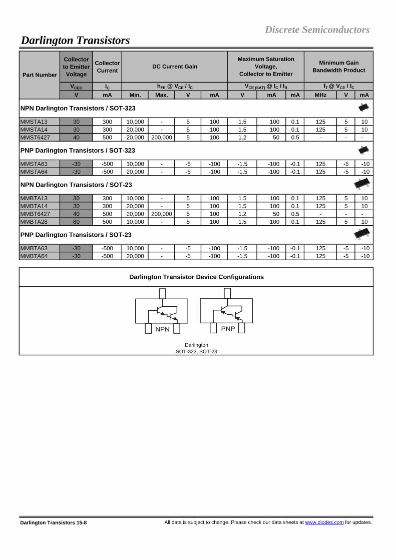
Collector to Emitter Voltage
Collector Current
VCEO ICV mA Min. Max. V mA V mA mA MHz V mA
MMSTA13 30 300 10,000 - 5 100 1.5 100 0.1 125 5 10MMSTA14 30 300 20,000 - 5 100 1.5 100 0.1 125 5 10MMST6427 40 500 20,000 200,000 5 100 1.2 50 0.5 - - -
MMSTA63 -30 -500 10,000 - -5 -100 -1.5 -100 -0.1 125 -5 -10MMSTA64 -30 -500 20,000 - -5 -100 -1.5 -100 -0.1 125 -5 -10
MMBTA13 30 300 10,000 - 5 100 1.5 100 0.1 125 5 10MMBTA14 30 300 20,000 - 5 100 1.5 100 0.1 125 5 10MMBT6427 40 500 20,000 200,000 5 100 1.2 50 0.5 - - -MMBTA28 80 500 10,000 - 5 100 1.5 100 0.1 125 5 10
MMBTA63 -30 -500 10,000 - -5 -100 -1.5 -100 -0.1 125 -5 -10MMBTA64 -30 -500 20,000 - -5 -100 -1.5 -100 -0.1 125 -5 -10
Darlington Transistors 15-8 All data is subject to change. Please check our data sheets at www.diodes.com for updates.
DC Current Gain
VCE (SAT) @ IC / IB
Darlington Transistor Device Configurations
DarlingtonSOT-323, SOT-23
fT @ VCE / IC
Minimum Gain Bandwidth Product
Discrete Semiconductors
NPN Darlington Transistors / SOT-23
PNP Darlington Transistors / SOT-23
Maximum Saturation Voltage,
Collector to Emitter
hFE @ VCE / IC
NPN Darlington Transistors / SOT-323
PNP Darlington Transistors / SOT-323
Darlington Transistors
Part Number

Max. OutputCurrent
IO(MAX), IC(MAX)mA Typ. (V) Max. (V) Min. Typ. / Max.100 0.1 0.3 20 -
R1 R2 DFN1006-3 SOT-523 SOT-323 SOT-23 SC-59NPN PNP KΩ KΩ 250mW 150mW 200mW 200mW 200mW
DDTC123E( ) DDTA123E( ) 2.2 2.2 - E UA CA KADDTC143E( ) DDTA143E( ) 4.7 4.7 - E UA CA KADDTC114E( ) DDTA114E( ) 10 10 LP (NPN only) E UA CA KADDTC124E( ) DDTA124E( ) 22 22 - E UA CA KADDTC144E( ) DDTA144E( ) 47 47 LP (PNP only) E UA CA KADDTC115E( ) DDTA115E( ) 100 100 - E UA CA KADDTC122L( ) DDTA122L( ) 0.22 10 - E U - -DDTC142J( ) DDTA142J( ) 0.47 10 - E U - -DDTC113Z( ) DDTA113Z( ) 1 10 - E UA CA KADDTC123Y( ) DDTA123Y( ) 2.2 10 - E UA CA KADDTC123J( ) DDTA123J( ) 2.2 47 LP (NPN only) E UA CA KADDTC143X( ) DDTA143X( ) 4.7 10 - E UA CA KADDTC143F( ) DDTA143F( ) 4.7 22 - E UA CA KADDTC143Z( ) DDTA143Z( ) 4.7 47 LP (NPN only) E UA CA KADDTC114W( ) DDTA114W( ) 10 4.7 - E UA CA KADDTC114Y( ) DDTA114Y( ) 10 47 LP E UA CA KADDTC124X( ) DDTA124X( ) 22 47 - E UA CA KADDTC144V( ) DDTA144V( ) 47 10 - E UA CA KADDTC144W( ) DDTA144W( ) 47 22 - E UA CA KADDTC122T( ) DDTA122T( ) 0.22 - - E U - -DDTC142T( ) DDTA142T( ) 0.47 - - E U - -DDTC113T( ) DDTA113T( ) 1 - LP (NPN only) E UA CA KADDTC123T( ) DDTA123T( ) 2.2 - - E UA CA KADDTC143T( ) DDTA143T( ) 4.7 - - E UA CA KADDTC114T( ) DDTA114T( ) 10 - - E UA CA KADDTC124T( ) DDTA124T( ) 22 - - E UA CA KADDTC144T( ) DDTA144T( ) 47 - - E UA CA KADDTC115T( ) DDTA115T( ) 100 - - E UA CA KADDTC125T( ) DDTA125T( ) 200 - - E UA CA KADDTC114G( ) DDTA114G( ) - 10 - E UA CA KADDTC124G( ) DDTA124G( ) - 22 - E UA CA KADDTC144G( ) DDTA144G( ) - 47 - E UA CA KADDTC115G( ) DDTA115G( ) - 100 - E UA CA KA
All data is subject to change. Please check our data sheets at www.diodes.com for updates. NPN, PNP Prebiased Transistors 16-1
NPN, PNP Prebiased Transistors
R2 Only
BiasResistors Part Number Suffix
R1 = R2
R1 ≠ R2
MHz250
R1 Only
V50
SeriesPart Number
Single 100mA Prebiased Transistors
Discrete Semiconductors
VCE, VCEO, VCC VCE (SAT), VO(ON) hFE
Gain Bandwidth Product
Transistor
fT
Collector toEmitter Voltage
Saturation Voltage, Collector to
Emitter
DC Current Transfer Ratio, Transistor

Max. OutputCurrent
Gain Bandwidth
ProductTransistor
IO(MAX), IC(MAX) fTmA Typ. (V) Max. (V) Min. Typ. / Max. MHz500 0.1 0.3 20 - 250
R1 R2 SOT-323NPN PNP KΩ KΩ 200mW
DDTD113E( ) DDTB113E( ) 1 1 UDDTD123E( ) DDTB123E( ) 2.2 2.2 UDDTD143E( ) DDTB143E( ) 4.7 4.7 UDDTD114E( ) DDTB114E( ) 10 10 UDDTD122J( ) DDTB122J( ) 0.22 4.7 UDDTD122L( ) DDTB122L( ) 0.22 10 UDDTD142J( ) DDTB142J( ) 0.47 10 UDDTD113Z( ) DDTB113Z( ) 1 10 UDDTD123Y( ) DDTB123Y( ) 2.2 10 UDDTD133H( ) DDTB133H( ) 3.3 10 UDDTD122T( ) DDTB122T( ) 0.22 - UDDTD142T( ) DDTB142T( ) 0.47 - UDDTD123T( ) DDTB123T( ) 2.2 - UDDTD143T( ) DDTB143T( ) 4.7 - UDDTD114T( ) DDTB114T( ) 10 - U
R2 Only DDTD114G( ) DDTB114G( ) 0 10 U
Max. OutputCurrent
Gain Bandwidth
ProductTransistor
IO(MAX), IC(MAX) fTmA Typ. (V) Max. (V) Min. Typ. / Max. MHz100 0.1 0.3 20 - 250
R1 R2 SOT-563 SOT-363 SOT-26NPN PNP KΩ KΩ 150mW 200mW 300mW
DDC143E( ) DDA143E( ) 4.7 4.7 H U -DDC114E( ) DDA114E( ) 10 10 H U K (PNP only)DDC124E( ) DDA124E( ) 22 22 H U K (PNP only)DDC144( ) DDA144( ) 47 47 EH EU, NS EK (PNP only)DDC122L( ) DDA122L( ) 0.22 10 H U -DDC142J( ) DDA142J( ) 0.47 10 H U -DDC123J( ) DDA123J( ) 2.2 47 H U K (PNP only)DDC114Y( ) DDA114Y( ) 10 47 H U K (PNP only)DDC122T( ) DDA122T( ) 0.22 - H U -DDC142T( ) DDA142T( ) 0.47 - H U -DDC143T( ) DDA143T( ) 4.7 - H U K (PNP only)DDC114T( ) DDA114T( ) 10 - H U K (PNP only)DDC144T( ) - 47 - - U -
NPN, PNP Prebiased Transistors 16-2 All data is subject to change. Please check our data sheets at www.diodes.com for updates.
NPN, PNP Prebiased Transistors
R1 = R2
R1 ≠ R2
R1 Only
CC
CC
C
C
C
Part Number Suffix
Part Number Suffix
Dual 100mA Prebiased Transistors
C
SeriesPart Number
C
C
C
Bias Resistors
CCC
C
Discrete Semiconductors
V50
VCE, VCEO, VCC VCE (SAT), VO(ON) hFE
Collector toEmitter Voltage
Saturation Voltage, Collector to Emitter
DC Current Transfer Ratio, Transistor
R1 Only
R1 ≠ R2
R1 = R2
Single 500mA Prebiased Transistors
SOT-23200mW
SeriesPart Number
Bias Resistors
C
DC Current Transfer Ratio, Transistor
VCE, VCEO, VCC VCE (SAT), VO(ON) hFEV50
Collector toEmitter Voltage
Saturation Voltage, Collector to Emitter

Max. OutputCurrent
Collector toEmitter Voltage
IO(MAX), IC(MAX)
VCE, VCEO, VCC
mA V Typ. (V) Max. (V) Min. Typ. / Max.100 50 0.1 0.3 20 -
R1(PNP) R2(PNP) R1(NPN) R2(NPN) SOT-563 SOT-363 SC-74RKΩ KΩ KΩ KΩ 150mW 200mW 300mW
DCX143E( ) 4.7 4.7 4.7 4.7 H U -DCX114E( ) 10 10 10 10 H U KDCX124E( ) 22 22 22 22 H U KDCX144E( ) 47 47 47 47 H U KDCX122L( ) 0.22 10 0.22 10 H U -DCX142J( ) 0.47 10 0.47 10 H U -DCX123J( ) 2.2 47 2.2 47 H U KDCX114Y( ) 10 47 10 47 H U KDCX122T( ) 0.22 - 0.22 - H U -DCX142T( ) 0.47 - 0.47 - H U -DCX143T( ) 4.7 - 4.7 - H U KDCX114T( ) 10 - 10 - H U K
NPN/PNP R1(PNP) ≠ R2(PNP) = R1(NPN) = R2(NPN)
DCX100NS(SOT-563) 1 10 10 10 See Part
Number - -
NPN/PNP R2(PNP) ≠ R1(PNP) = R1(NPN) = R2(NPN)
DCX4710H(SOT-563) 10 47 10 10 See Part
Number - -
R1(PNP) R2(PNP) R1(NPN) R2(NPN)KΩ KΩ KΩ KΩ
MIMD10A 0.1 10 10 - SOT-363
DIMD10A 0.1 10 10 - SC-74R
All data is subject to change. Please check our data sheets at www.diodes.com for updates. NPN, PNP Prebiased Transistors 16-3
MHz
Complementary 100mA NPN / 500mA PNP
R1 ≠ R2
200
300
Series Part NumberBias Resistors
Power (mW) Package
Part Number
Saturation Voltage, Collector to Emitter
DC Current Transfer Ratio, Transistor
VCE (SAT), VO(ON) hFE
Complementary NPN/PNP R1 Only
Part Number Suffix
250
Dual 100mA Complementary Prebiased Transistors
100mA NPN / 500mA PNP Complementary Prebiased Transistors
Discrete SemiconductorsNPN, PNP Prebiased Transistors
Complementary NPN/PNP R1 = R2
SeriesBias Resistors
Gain Bandwidth Product
Transistor
fT
Complementary NPN/PNP R1 ≠ R2

NPN, PNP Prebiased Transistors 16-4 All data is subject to change. Please check our data sheets at www.diodes.com for updates.
NPN, PNP Prebiased Transistor Configurations (Dual)
Discrete SemiconductorsNPN, PNP Prebiased Transistors
NPN, PNP Prebiased Transistor Configurations (Single, DFN1006-3)
NPN, PNP Prebiased Transistor Configurations (Single, SOT-523, SOT-323, SOT-23, SC-59)

Drain-Source Voltage
Gate-Source Voltage
Drain Current
Gate Threshold
Voltage
Zero Gate Voltage-
Drain Current
Input Capa-
citance
VDSS VGSS ID MAX VGS(TH) MAX IDSS CISS
V +/-V mA Ω V/A V µA Max. (pF)
DMN2005LP4K 20 10 200 1.5 4/0.01 0.9 10 40 (Typ.) Fig. 1
DMN2005LPK 20 10 440 1.5 4/0.01 1.2 10 40 (Typ.) Fig. 1
DMN2005DLP4K 20 10 200 1.5 4/0.01 0.9 10 40 (Typ.) Fig. 2
DMP2104LP -20 12 -1500 0.15 -4.5/-0.95 -1 -1 320 (Typ.) Fig. 16
DMC2004LPK 20/-20 8 750/-600 0.55/0.9 4.5/0.54, -4.5/-0.43 1.0/ -1.0 1/ -1 150/175 Fig. 17
2N7002VAC 60 20 280 7.5 5/0.05 2.5 1 50 Fig. 32N7002VC 60 20 280 7.5 5/0.05 2.5 1 50 Fig. 4DMN2004VK 20 8 540 0.55 4.5/0.54 1 1 150 Fig. 5DMN32D2LV 30 10 400 1.2 4/0.1 1.2 1 39 Fig. 5DMN5010VAK 50 20 280 2 5/0.05 1 0.06 50 Fig. 6DMN5L06VAK 50 20 280 2 5/0.05 1 0.06 50 Fig. 6DMN5L06VK 50 20 280 2 5/0.05 1 0.06 50 Fig. 5DMN601VK 60 20 305 3 4.5/0.2 2.5 0.25 50 Fig. 5
DMP2104V -20 12 -950 0.15 -4.5/-0.95 -1 -1 320 Fig. 7
BSS84V -50 20 -130 10 -5/-0.1 -2 -15 45 Fig. 8DMP2004VK -20 8 -530 0.9 -4.5/-0.43 -1 -1 175 Fig. 9
DMC2004VK 20/-20 8 670/ -530 0.55/ 0.9 4.5/0.54, -4.5/-0.43 1.0/ -1.0 1/ -1 150/175 Fig. 10
2N7002W 60 20 115 7.5 5/0.05 2 1 50 Fig. 11BSS123W 100 20 170 6 10/0.17 2 1 60 Fig. 11BSS138W 50 20 200 3.5 10/0.22 1.5 0.5 50 Fig. 11DMN2004WK 20 8 540 0.55 4.5/0.54 1 1 150 Fig. 12DMN5L06WK 50 20 300 2 5.0/0.05 1 0.06 50 Fig. 12DMN601WK 60 20 300 3 4.5/0.2 2.5 1 50 Fig. 12
BSS84W -50 20 -130 10 -5/-0.1 -2 -15 45 Fig. 13DMP2004WK -20 8 -530 0.9 -4.5/-0.43 -1 -1 175 Fig. 14
All data is subject to change. Please check our data sheets at www.diodes.com for updates. MOSFETs 17-1
Discrete Semiconductors
Dual P-Channel MOSFET / SOT-563
P-Channel MOSFET / SOT-323
Complementary (N / P Channel) MOSFET / SOT-563
N-Channel MOSFET / SOT-323
P-Channel MOSFET / DFN1411-3
Complementary (N / P Channel) MOSFET / DFN1612-6
N-Channel MOSFET / DFN1006-3
Dual N-Channel MOSFET DFN1310H4-6 (0.4mm Profile)
Dual N-Channel MOSFET / SOT-563
N-Channel MOSFET / DFN1006H4-3 (0.4mm Profile)
MOSFETs
Pin-out Config. Part Number
Static Drain-Source On Resistance
RDS(ON) Max. @ VGS / ID
Single P-Channel MOSFET / SOT-563

Drain-Source Voltage
Gate-Source Voltage
Drain Current
Gate Threshold
Voltage
Zero Gate Voltage-
Drain Current
Input Capa-
citance
VDSS VGSS ID MAX VGS(TH) MAX IDSS CISS
V +/-V mA Ω V/A V µA Max. (pF)
2N7002DW 60 20 115 7.5 5/0.05 2 1 50 Fig. 4BSS138DW 50 20 200 3.5 10/0.22 1.5 0.5 50 Fig. 4DMN2004DWK 20 8 540 0.55 4.5/0.54 1 1 150 Fig. 5DMN5L06DWK 50 20 305 2 5.0/0.05 1 0.06 50 Fig. 5DMN601DWK 60 20 305 3 5/0.05 2.5 1 50 Fig. 5
BSS8402DW 60/-50 20 115/-130 7.5 / 10 5/0.05, -5/-0.1 2.5/-2.0 1.0/-15 50/45 Fig. 15DMC2004DWK 20/-20 8 540/ -430 0.55/ 0.9 4.5/0.54, -4.5/-0.43 1.0/ -1.0 1/ -1 150/175 Fig. 10
DMP2004DWK -20 8 -430 0.9 -4.5/ -0.43 -1 -1 175 Fig. 9BSS84DW -50 20 -130 10 50 -2 -15 45 Fig. 8
2N7002 60 20 115 7.5 5/0.05 2.5 1 50 Fig. 112N7002E 60 20 240 3 10/0.25 2.5 1 50 Fig. 112N7002K 60 20 300 3 5/0.05 2.5 1 50 Fig. 12BS870 60 20 250 5 10/0.20 3 0.5 50 Fig. 11BSS123 100 20 170 6 10/0.17 2 1 60 Fig. 11BSS138 50 20 200 3.5 10/0.22 1.5 0.5 50 Fig. 11DMN2004K 20 8 540 0.55 4.5/0.54 1 1 150 Fig. 12DMN2005K 20 10 300 1.7 2.7/0.2 0.9 10 40 (Typ) Fig. 12DMN3150L 28 12 3100 0.085 4.5/3.1 1.4 0.8 305 (Typ.) Fig. 11DMN5L06K 50 20 300 2 5.0/0.05 1 0.06 50 Fig. 12DMN601K 60 20 300 3 5/0.05 2.5 1 50 Fig. 12MMBF170 60 20 500 5 10/0.2 3 1 40 Fig. 11
BSS84 -50 20 -130 10 -5.0/-0.1 -2 -15 45 Fig. 13DMP2004K -20 8 -600 0.9 -4.5/ -0.43 -1 -1 175 Fig. 14DMP2215L -20 12 2700 0.1 -4.5/-2.7 -1.25 -0.8 250 (Typ.) Fig. 13
DMN2004DMK 20 8 540 0.55 4.5/0.54 1 1 150 Fig. 5DMN5L06DMK 50 20 305 2 5.0/0.05 1 0.06 50 Fig. 5DMN601DMK 60 20 305 2.4 10/0.2 2.5 1 50 Fig. 5
DMP2130LDM -20 12 -3400 0.08 -4.5/-4.5 -1.25 -1 240 (Typ.) Fig. 7
DMP2004DMK -20 8 -430 0.9 -4.5/ -0.43 -1 -1 175 Fig. 9DMP2240UDM -20 12 -2000 0.15 -4.5/ -2.0 -1.0 -1 320 (Typ.) Fig. 18
MOSFETs 17-2 All data is subject to change. Please check our data sheets at www.diodes.com for updates.
Discrete Semiconductors
N-Channel MOSFET / SOT-23
Dual N-Channel MOSFET / SOT-26
Dual P-Channel MOSFET / SOT-26
P-Channel MOSFET / SOT-26
MOSFETs
Dual N-Channel MOSFET / SOT-363
Dual P-Channel MOSFET / SOT-363
RDS(ON) Max. @ VGS / ID
Complementary (N / P Channel) MOSFET / SOT-363
P-Channel MOSFET / SOT-23
Part Number
Static Drain-Source On Resistance Pin-out
Config.

Drain-Source Voltage
Gate-Source Voltage
Drain Current
Gate Threshold
Voltage
Zero Gate Voltage-
Drain Current
Input Capa-
citance
VDSS VGSS ID MAX VGS(TH) MAX IDSS CISS
V +/-V mA Ω V/A V µA Max. (pF)
DMN100 30 20 1100 0.17 4.5/0.50 3 1 150 (Typ.) Fig. 12DMN2112SN 20 8 1200 0.10 4.5/0.05 1.2 10 220 (Typ.) Fig. 12DMN2114SN 20 12 1200 0.1 4.5/0.5 1.4 10 180 (Typ.) Fig. 12DMN3033LSN 30 20 6000 0.03 10/6 2.1 1 755 (Typ.) Fig. 12
DMP2012SN -20 12 -700 0.3 -4.5/-0.4 -1.2 -10 180 (Typ.) Fig. 14DMP3030SN -30 20 -700 0.25 -10/-0.4 -3 -10 160 (Typ.) Fig. 14
All data is subject to change. Please check our data sheets at www.diodes.com for updates. MOSFETs 17-3
Discrete Semiconductors
Figure 4Dual N-Channel
SOT-363, SOT-563
Figure 5Dual N-Channel with ESD Protected Gate
SOT-563, SOT-26, SOT-363
Figure 6Dual N-Channel with ESD Protected Gate
Alternate Pin-out Config. SOT-563
Figure 7Single P-Channel SOT-563, SOT-26
Figure 8Dual P-Channel
SOT-563, SOT-363
Figure 9Dual P-Channel with ESD Protected Gate
SOT-563, SOT-26, SOT-363
P-Channel MOSFET / SC-59
Figure 1Single N-Channel with ESD Protected Gate
DFN1006H4-3, DFN1006-3
Figure 2Dual N-Channel with ESD Protected Gate
DFN1310H4-6
Figure 3 Dual N-Channel
SOT-563
MOSFET Configurations
Static Drain-Source On Resistance Pin-out
Config. RDS(ON) Max. @ VGS / ID
Part Number
N-Channel MOSFET / SC-59
MOSFETs

MOSFETs 17-4 All data is subject to change. Please check our data sheets at www.diodes.com for updates.
Discrete Semiconductors
Figure 10Dual Complementary (N/P-Channel)
with ESD Protected GateSOT-563, SOT-363
Figure 11Single N-Channel
SOT-523, SOT-323, SOT-23, SC-59
Figure 12Single N-Channel with ESD
Protected GateSOT-523, SOT-323, SOT-23, SC-59
MOSFET Configurations
Figure 16Single P-Channel
DFN1411-3
Figure 17Dual Complementary (N/P-Channel)
with ESD Protected GateDFN1612-6
Figure 18Dual P-Channel
SOT-26
Figure 13 Single P-Channel
SOT-323, SOT-23, SC-59
Figure 14Single P-Channel with ESD Protection
SOT-23, SOT-323, SC-59
Figure 15 Dual Complementary
(N/P-Channel)SOT-363
MOSFETs

R1 - PBT (Ω)
R2 - PBT (Ω)
CTA2N1P NPN Transistor + P-Channel MOSFET 600 60 -50 N/A N/A N/A
LMN200B02
Pre-Biased PNP Transistor + N-Channel MOSFET with Pull Down Resistor
-200 -50 60 10K 470 37K
LMN400E01
Pre-Biased PNP Transistor + N-Channel MOSFET with Gate ESD Protection
-400 -50 60 10K 220 N/A
CTA2P1N PNP Transistor + N-Channel MOSFET -600 -40 60 N/A N/A N/A
LMN200B01
Pre-Biased PNP Transistor + N-Channel MOSFET with Pull Down Resistor
-200 -50 60 10K 470 37K
LMN400B01
Pre-Biased PNP Transistor + N-Channel MOSFET with Pull Down Resistor
-400 -50 60 10K 220 37K
All data is subject to change. Please check our data sheets at www.diodes.com for updates. Complex Arrays 18-1
Discrete - Load Switches / SOT-363
Discrete - Load Switches / SOT-26
Part Number Description Device Schematic
Complex ArraysDiscrete Semiconductors
Maximum Collector
Current IC - Transistor
(mA)
Maximum Collector to
Base Voltage VCBO
- Transistor (V)
Maximum Drain to Source
Voltage VDSS
- MOSFET (V)
Bias ResistorsR3 - Pull
Down (Ω)

RDS (ON)
(Ω)
@ VDS
(V) / ID
(mA)
VF @ IF
(V)IF (mA)
DMS2700UFDB
N-ChannelMOSFET with Gate ESDProtection +Schottky BarrierDiode
540 20 0.9 1.8/350 30 0.42 1000
NMSD200B01
N-ChannelMOSFET with Gate ESDProtection +Schottky BarrierDiode
200 60 2 10/500 40 0.6 200
NPN PNP NPN PNP VCE / IC VCE / IC
V V mA mA V / mA V / mA
HBDM60V600W NPN Transistor + PNP Transistor 65 -60 500 -600 100 1/100 100 -10 /
-150
Complex Arrays 18-2 All data is subject to change. Please check our data sheets at www.diodes.com for updates.
Discrete SemiconductorsComplex Arrays
Maximum Forward
Voltage Drop VF - Schottky
Device Schematic
Collector to Emitter Voltage
VCEO
Collector Current IC
hFE hFE
NPN PNP
Discrete - Half H-Bridge Motor Driver / SOT-363
Part Number Description
Maximum Drain
Current ID
- MOSFET
(mA)
MOSFET and Schottky Arrays / DFN2020B-6
MOSFET and Schottky Arrays / SOT-363
Minimum DC Current GainhFE @ VCE / IC
Maximum Drain to Source Voltage VDSS -
MOSFET (V)
Static Drain-Source On Resistance
RDS(ON) - MOSFET
Peak Repetitive Reverse Voltage VRRM -
Schottky Diode (V)
Part Number Configuration Device Schematic

Maximum Collector to Emitter Voltage
Maximum Collector Current
Bias Resistors
Peak Repetitive Reverse Voltage
Maximum Average Rectifier Current
VCEO / VCC IC R1 / R2 VRRM IOV mA Ω V mA
DRDP006W PNP Transistor / Switching Diode-Relay Driver -60 -600 - 75 250
DRDPB16W 1K/10K
DRDPB26W 220/4.7K
DRDN010W 18 1000 -
DRDN005W 80 500 -
DRDNB16W 1K/10K
DRDNB26W 220/4.7K
DRDNB21DNPN Pre-biased Transistor R1-R2 / Switching Diode-Dual Relay Driver
50 200 2.2K/47K 75 250
All data is subject to change. Please check our data sheets at www.diodes.com for updates. Complex Arrays 18-3
75
75 250
PNP Pre-biased Transistor R1-R2 / Switching Diode-Relay Driver
-50 -600
Relay Drivers / SOT-363
Discrete Semiconductors
NPN Pre-biased TransistorR1-R2 / Switching Diode-Relay Driver
50 600
250
NPN Transistor / Switching Diode-Relay Driver 75 250
Complex Arrays
Part Number Description Device Schematic
Transistor / PBT Section Switching Diode

Part Number Description Device Schematic Vo (nom) (V)Output
Current Io (mA)
Typical Vreg(load) from Io = 100mA to 0mA (V)
Typical Iq @ Io = 0mA (mA)
DVR1V8W NPN Transistor / Zener Diode- Voltage Regulator 1.8 100 0.25 0.55
DVR2V5W NPN Transistor / Zener Diode- Voltage Regulator 2.5 100 0.13 0.91
DVR3V3W NPN Transistor / Zener Diode- Voltage Regulator 3.3 100 0.21 0.70
DVR5V0W NPN Transistor / Zener Diode- Voltage Regulator 5 100 0.20 0.50
Complex Arrays 18-4 All data is subject to change. Please check our data sheets at www.diodes.com for updates.
Complex ArraysDiscrete Semiconductors
Discrete - Voltage Regulators / SOT-363

Peak Repetitive Reverse Voltage
Peak Forward Surge Current
(†)
Maximum Reverse
Recovery Time (†)
VRRM IFSM trr
V A oC A V A µA V ns
DFLU1200 200 1 25* 30 0.98 1 5 200 25DFLU1400 400 1 25* 30 1.25 1 5 400 25
ES1A 50 1 110 30 0.98 1 5 50 25ES1B 100 1 110 30 0.98 1 5 100 25ES1C 150 1 110 30 0.98 1 5 150 25ES1D 200 1 110 30 0.98 1 5 200 25ES1G 400 1 110 30 1.25 1 5 400 35
MURS120 200 1 155 40 0.875 1 2 200 25MURS140 400 1 150 35 1.25 1 5 400 50MURS160 600 1 150 35 1.25 1 5 600 50
SF10AG 50 1 75 30 0.95 1 10 50 35SF10BG 100 1 75 30 0.95 1 10 100 35SF10CG 150 1 75 30 0.95 1 10 150 35MUR120 200 1 130 35 0.875 1 2 200 25SF10DG 200 1 75 30 0.95 1 10 200 35SF10FG 300 1 75 30 1.3 1 10 300 40MUR140 400 1 120 35 1.25 1 5 400 50SF10GG 400 1 75 30 1.3 1 10 400 40SF10HG 500 1 75 30 1.5 1 10 500 50MUR160 600 1 120 35 1.25 1 5 600 50SF10JG 600 1 75 30 1.5 1 10 600 50
US1A 50 1 75 30 1 1 5 50 50US1B 100 1 75 30 1 1 5 100 50US1D 200 1 75 30 1 1 5 200 50US1G 400 1 75 30 1.3 1 5 400 50US1J 600 1 75 30 1.7 1 5 600 75US1K 800 1 75 30 1.7 1 5 800 75US1M 1000 1 75 30 1.7 1 5 1000 75
UF1001 50 1 55 30 1 1 5 50 50UF1002 100 1 55 30 1 1 5 100 50UF1003 200 1 55 30 1 1 5 200 50UF1004 400 1 55 30 1.3 1 5 400 50UF1005 600 1 55 30 1.7 1 5 600 75UF1006 800 1 55 30 1.7 1 5 800 75UF1007 1000 1 55 30 1.7 1 5 1000 75
All data is subject to change. Please check our data sheets at www.diodes.com for updates. Super-Fast / Ultra-Fast / Fast Recovery Rectifiers 19-1
Discrete Semiconductors
1.0A Super-Fast Recovery Glass Passivated Rectifiers / PowerDI®123
Part Number
Max. Average Rectified Current (†)
Max. Forward Voltage Drop
Max. Reverse Current (†)
IO @ TT VF @ IF IR @ VR
1.0A Ultra-Fast Recovery Glass Passivated Rectifiers / SMA
Super-Fast / Ultra-Fast / Fast Recovery Rectifiers
1.0A Super-Fast Recovery Glass Passivated Rectifiers / SMA
1.0A Super-Fast Recovery Glass Passivated Rectifiers / SMB
1.0A Super-Fast Recovery Glass Passivated Rectifiers / DO-41
1.0A Ultra-Fast Recovery Rectifiers / DO-41
(†) Reference product data sheet for specific test conditions.
* TA, Ambient Temperature

Peak Repetitive Reverse Voltage
Peak Forward Surge Current
(†)
Maximum Reverse
Recovery Time (†)
VRRM IFSM trr
V A oC A V A µA V ns
UG1001 50 1 55 30 1 1 5 50 50UG1002 100 1 55 30 1 1 5 100 50UG1003 200 1 55 30 1 1 5 200 50UG1004 400 1 55 30 1.3 1 5 400 50UG1005 600 1 55 30 1.7 1 5 600 75
RS1A 50 1 120 30 1.3 1 5 50 150RS1B 100 1 120 30 1.3 1 5 100 150RS1D 200 1 120 30 1.3 1 5 200 150RS1G 400 1 120 30 1.3 1 5 400 150RS1J 600 1 120 30 1.3 1 5 600 250RS1K 800 1 120 30 1.3 1 5 800 500RS1M 1000 1 120 30 1.3 1 5 1000 500
RS1AB 50 1 120 30 1.3 1 5 50 150RS1BB 100 1 120 30 1.3 1 5 100 150RS1DB 200 1 120 30 1.3 1 5 200 150RS1GB 400 1 120 30 1.3 1 5 400 150RS1JB 600 1 120 30 1.3 1 5 600 250RS1KB 800 1 120 30 1.3 1 5 800 500RS1MB 1000 1 120 30 1.3 1 5 1000 500
1N4933L 50 1 75 30 1.2 1 5 50 200PR1001L 50 1 75 30 1.2 1 5 50 1501N4934L 100 1 75 30 1.2 1 5 100 200PR1002L 100 1 75 30 1.2 1 5 100 1501N4935L 200 1 75 30 1.2 1 5 200 200PR1003L 200 1 75 30 1.2 1 5 200 1501N4936L 400 1 75 30 1.2 1 5 400 200PR1004L 400 1 75 30 1.2 1 5 400 1501N4937L 600 1 75 30 1.2 1 5 600 200PR1005L 600 1 75 30 1.2 1 5 600 250
Super-Fast / Ultra-Fast / Fast Recovery Rectifiers 19-2 All data is subject to change. Please check our data sheets at www.diodes.com for updates.
IO @ TT VF @ IF IR @ VR
1.0A Fast Recovery Glass Passivated Rectifiers / SMA
1.0A Fast Recovery Glass Passivated Rectifiers / SMB
1.0A Fast Recovery Rectifiers / A-405
Discrete SemiconductorsSuper-Fast / Ultra-Fast / Fast Recovery Rectifiers
Part Number
Max. Average Rectified Current (†)
Max. Forward Voltage Drop
Max. Reverse Current (†)
1.0A Ultra-Fast Recovery Glass Passivated Rectifiers / DO-41
(†) Reference product data sheet for specific test conditions.

Peak Repetitive Reverse Voltage
Peak Forward Surge Current
(†)
Maximum Reverse
Recovery Time (†)
VRRM IFSM trr
V A oC A V A µA V ns
1N4933GL 50 1 75 30 1.2 1 5 50 200PR1001GL 50 1 55 30 1.3 1 5 50 1501N4934GL 100 1 75 30 1.2 1 5 100 200PR1002GL 100 1 55 30 1.3 1 5 100 1501N4935GL 200 1 75 30 1.2 1 5 200 200PR1003GL 200 1 55 30 1.3 1 5 200 1501N4936GL 400 1 75 30 1.2 1 5 400 200PR1004GL 400 1 55 30 1.3 1 5 400 1501N4937GL 600 1 75 30 1.2 1 5 600 200PR1005GL 600 1 55 30 1.3 1 5 600 250PR1006GL 800 1 55 30 1.3 1 5 800 500PR1007GL 1000 1 55 30 1.3 1 5 1000 500
1N4933 50 1 75 30 1.2 1 5 50 200PR1001 50 1 75 30 1.2 1 5 50 1501N4934 100 1 75 30 1.2 1 5 100 200PR1002 100 1 75 30 1.2 1 5 100 1501N4935 200 1 75 30 1.2 1 5 200 200PR1003 200 1 75 30 1.2 1 5 200 1501N4936 400 1 75 30 1.2 1 5 400 200PR1004 400 1 75 30 1.2 1 5 400 1501N4937 600 1 75 30 1.2 1 5 600 200PR1005 600 1 75 30 1.2 1 5 600 250
1N4933G 50 1 75 30 1.2 1 5 50 200PR1001G 50 1 55 30 1.3 1 5 50 1501N4934G 100 1 75 30 1.2 1 5 100 200PR1002G 100 1 55 30 1.3 1 5 100 1501N4935G 200 1 75 30 1.2 1 5 200 200PR1003G 200 1 55 30 1.3 1 5 200 1501N4936G 400 1 75 30 1.2 1 5 400 200PR1004G 400 1 55 30 1.3 1 5 400 1501N4937G 600 1 75 30 1.2 1 5 600 200PR1005G 600 1 55 30 1.3 1 5 600 250PR1006G 800 1 55 30 1.3 1 5 800 500PR1007G 1000 1 55 30 1.3 1 5 1000 500
UF1501S 50 1.5 50 50 1 1.5 5 50 50UF1502S 100 1.5 50 50 1 1.5 5 100 50UF1503S 200 1.5 50 50 1 1.5 5 200 50UF1504S 400 1.5 50 50 1.3 1.5 5 400 50UF1505S 600 1.5 50 50 1.7 1.5 5 600 75UF1506S 800 1.5 50 50 1.7 1.5 5 800 75UF1507S 1000 1.5 50 50 1.7 1.5 5 1000 75
All data is subject to change. Please check our data sheets at www.diodes.com for updates. Super-Fast / Ultra-Fast / Fast Recovery Rectifiers 19-3
1.0A Fast Recovery Glass Passivated Rectifiers / A-405
Discrete SemiconductorsSuper-Fast / Ultra-Fast / Fast Recovery Rectifiers
Part Number
Max. Average Rectified Current (†)
Max. Forward Voltage Drop
Max. Reverse Current (†)
IO @ TT VF @ IF IR @ VR
1.0A Fast Recovery Rectifiers / DO-41
1.0A Fast Recovery Glass Passivated Rectifiers / DO-41
1.5A Ultra-Fast Recovery Rectifiers / DO-41
(†) Reference product data sheet for specific test conditions.

Peak Repetitive Reverse Voltage
Peak Forward Surge Current
(†)
Maximum Reverse
Recovery Time (†)
VRRM IFSM trr
V A oC A V A µA V ns
UF1501 50 1.5 50 50 1 1.5 5 50 50UF1502 100 1.5 50 50 1 1.5 5 100 50UF1503 200 1.5 50 50 1 1.5 5 200 50UF1504 400 1.5 50 50 1.3 1.5 5 400 50UF1505 600 1.5 50 50 1.7 1.5 5 600 75UF1506 800 1.5 50 50 1.7 1.5 5 800 75UF1507 1000 1.5 50 50 1.7 1.5 5 1000 75
RS2AA 50 1.5 120 50 1.3 1.5 5 50 150RS2BA 100 1.5 120 50 1.3 1.5 5 100 150RS2DA 200 1.5 120 50 1.3 1.5 5 200 150RS2GA 400 1.5 120 50 1.3 1.5 5 400 150RS2JA 600 1.5 120 50 1.3 1.5 5 600 250RS2KA 800 1.5 120 50 1.3 1.5 5 800 500RS2MA 1000 1.5 120 50 1.3 1.5 5 1000 500
RS2A 50 1.5 120 50 1.3 1.5 5 50 150RS2B 100 1.5 120 50 1.3 1.5 5 100 150RS2D 200 1.5 120 50 1.3 1.5 5 200 150RS2G 400 1.5 120 50 1.3 1.5 5 400 150RS2J 600 1.5 120 50 1.3 1.5 5 600 250RS2K 800 1.5 120 50 1.3 1.5 5 800 500RS2M 1000 1.5 120 50 1.3 1.5 5 1000 500
PR1501S 50 1.5 50 50 1.2 1.5 5 50 150PR1502S 100 1.5 50 50 1.2 1.5 5 100 150PR1503S 200 1.5 50 50 1.2 1.5 5 200 150PR1504S 400 1.5 50 50 1.2 1.5 5 400 150PR1505S 600 1.5 50 50 1.2 1.5 5 600 250
PR1501GS 50 1.5 55 50 1.3 1.5 5 50 150PR1502GS 100 1.5 55 50 1.3 1.5 5 100 150PR1503GS 200 1.5 55 50 1.3 1.5 5 200 150PR1504GS 400 1.5 55 50 1.3 1.5 5 400 150PR1505GS 600 1.5 55 50 1.3 1.5 5 600 250PR1506GS 800 1.5 55 50 1.3 1.5 5 800 500PR1507GS 1000 1.5 55 50 1.3 1.5 5 1000 500
PR1501 50 1.5 50 50 1.2 1.5 5 50 150PR1502 100 1.5 50 50 1.2 1.5 5 100 150PR1503 200 1.5 50 50 1.2 1.5 5 200 150PR1504 400 1.5 50 50 1.2 1.5 5 400 150PR1505 600 1.5 50 50 1.2 1.5 5 600 250
Super-Fast / Ultra-Fast / Fast Recovery Rectifiers 19-4 All data is subject to change. Please check our data sheets at www.diodes.com for updates.
Discrete SemiconductorsSuper-Fast / Ultra-Fast / Fast Recovery Rectifiers
Part Number
Max. Average Rectified Current (†)
Max. Forward Voltage Drop
Max. Reverse Current (†)
IO @ TT VF @ IF IR @ VR
1.5A Fast Recovery Glass Passivated Rectifiers / SMA
1.5A Fast Recovery Rectifiers / DO-41
1.5A Ultra-Fast Recovery Rectifiers / DO-15
(†) Reference product data sheet for specific test conditions.
1.5A Fast Recovery Glass Passivated Rectifiers / DO-41
1.5A Fast Recovery Rectifiers / DO-15
1.5A Fast Recovery Glass Passivated Rectifiers / SMB

Peak Repetitive Reverse Voltage
Peak Forward Surge Current
(†)
Maximum Reverse
Recovery Time (†)
VRRM IFSM trr
V A oC A V A µA V ns
PR1501G 50 1.5 55 50 1.3 1.5 5 50 150PR1502G 100 1.5 55 50 1.3 1.5 5 100 150PR1503G 200 1.5 55 50 1.3 1.5 5 200 150PR1504G 400 1.5 55 50 1.3 1.5 5 400 150PR1505G 600 1.5 55 50 1.3 1.5 5 600 250PR1506G 800 1.5 55 50 1.3 1.5 5 800 500PR1507G 1000 1.5 55 50 1.3 1.5 5 1000 500
ES2AA 50 2 110 50 0.92 2 5 50 25ES2BA 100 2 110 50 0.92 2 5 100 25ES2CA 150 2 110 50 0.92 2 5 150 25ES2DA 200 2 110 50 0.92 2 5 200 25
ES2A 50 2 110 50 0.92 2 5 50 25ES2B 100 2 110 50 0.92 2 5 100 25ES2C 150 2 110 50 0.92 2 5 150 25ES2D 200 2 110 50 0.92 2 5 200 25ES2G 400 2 110 50 1.25 2 5 400 35
SF20AG 50 2 75 60 0.95 2 10 50 35SF20BG 100 2 75 60 0.95 2 10 100 35SF20CG 150 2 75 60 0.95 2 10 150 35SF20DG 200 2 75 60 0.95 2 10 200 35SF20FG 300 2 75 60 1.3 2 10 300 40SF20GG 400 2 75 60 1.3 2 10 400 40SF20HG 500 2 75 60 1.5 2 10 500 50SF20JG 600 2 75 60 1.5 2 10 600 50
UF2001 50 2 50 60 1 2 5 50 50UF2002 100 2 50 60 1 2 5 100 50UF2003 200 2 50 60 1 2 5 200 50UF2004 400 2 50 60 1.3 2 5 400 50UF2005 600 2 50 60 1.7 2 5 600 75UF2006 800 2 50 60 1.7 2 5 800 75UF2007 1000 2 50 60 1.7 2 5 1000 75
UG2001 50 2 55 60 1 2 8 50 50UG2002 100 2 55 60 1 2 8 100 50UG2003 200 2 55 60 1 2 8 200 50UG2004 400 2 55 60 1.3 2 8 400 50UG2005 600 2 55 60 1.7 2 8 600 50
All data is subject to change. Please check our data sheets at www.diodes.com for updates. Super-Fast / Ultra-Fast / Fast Recovery Rectifiers 19-5
VF @ IF IR @ VR
2.0A Super-Fast Recovery Glass Passivated Rectifiers / SMA
Discrete SemiconductorsSuper-Fast / Ultra-Fast / Fast Recovery Rectifiers
Part Number
Max. Average Rectified Current (†)
Max. Forward Voltage Drop
Max. Reverse Current (†)
IO @ TT
2.0A Super-Fast Recovery Glass Passivated Rectifiers / SMB
2.0A Super-Fast Recovery Glass Passivated Rectifiers / DO-15
2.0A Ultra-Fast Recovery Rectifiers / DO-15
2.0A Ultra-Fast Recovery Glass Passivated Rectifiers / DO-15
1.5A Fast Recovery Glass Passivated Rectifiers / DO-15
(†) Reference product data sheet for specific test conditions.

Peak Repetitive Reverse Voltage
Peak Forward Surge Current
(†)
Maximum Reverse
Recovery Time (†)
VRRM IFSM trr
V A oC A V A µA V ns
PR2001 50 2 50 50 1.2 2 5 50 150PR2002 100 2 50 50 1.2 2 5 100 150PR2003 200 2 50 50 1.2 2 5 200 150PR2004 400 2 50 50 1.2 2 5 400 150PR2005 600 2 50 50 1.2 2 5 600 250
PR2001G 50 2 55 80 1.3 2 5 50 150PR2002G 100 2 55 80 1.3 2 5 100 150PR2003G 200 2 55 80 1.3 2 5 200 150PR2004G 400 2 55 80 1.3 2 5 400 150PR2005G 600 2 55 80 1.3 2 5 600 250PR2006G 800 2 55 80 1.3 2 5 800 500PR2007G 1000 2 55 80 1.3 2 5 1000 500
PDU340 400 3 40* 55 1.25 3 10 400 50
ES3AB 50 3 100 100 0.9 3 10 50 25ES3BB 100 3 100 100 0.9 3 10 100 25ES3CB 150 3 100 100 0.9 3 10 150 25ES3DB 200 3 100 100 0.9 3 10 200 25
ES3A 50 3 100 100 0.9 3 10 50 25ES3B 100 3 100 100 0.9 3 10 100 25ES3C 150 3 100 100 0.9 3 10 150 25ES3D 200 3 100 100 0.9 3 10 200 25MURS320 200 3 140 75 0.9 3 5 200 25
SF30AG 50 3 55 125 0.95 3 5 50 35SF30BG 100 3 55 125 0.95 3 5 100 35SF30CG 150 3 55 125 0.95 3 5 150 35SF30DG 200 3 55 125 0.95 3 5 200 35SF30FG 300 3 55 125 1.3 3 5 300 40SF30GG 400 3 55 125 1.3 3 5 400 40SF30HG 500 3 55 125 1.5 3 5 500 50SF30JG 600 3 55 125 1.5 3 5 600 50
Super-Fast / Ultra-Fast / Fast Recovery Rectifiers 19-6 All data is subject to change. Please check our data sheets at www.diodes.com for updates.
Discrete SemiconductorsSuper-Fast / Ultra-Fast / Fast Recovery Rectifiers
Part Number
VF @ IF IR @ VR
2.0A Fast Recovery Rectifiers / DO-15
3.0A Super-Fast Recovery Glass Passivated Rectifiers / DO-201AD
2.0A Fast Recovery Glass Passivated Rectifiers / DO-15
3.0A Ultra-Fast Recovery Glass Passivated Rectifiers / PowerDI®5
Max. Average Rectified Current (†)
Max. Forward Voltage Drop
Max. Reverse Current (†)
IO @ TT
3.0A Super-Fast Recovery Glass Passivated Rectifiers / SMB
3.0A Super-Fast Recovery Glass Passivated Rectifiers / SMC
* TA, Ambient Temperature
(†) Reference product data sheet for specific test conditions.

Peak Repetitive Reverse Voltage
Peak Forward Surge Current
(†)
Maximum Reverse
Recovery Time (†)
VRRM IFSM trr
V A oC A V A µA V ns
UF3001 50 3 55 150 1 3 5 50 50UF3002 100 3 55 150 1 3 5 100 50UF3003 200 3 55 150 1 3 5 200 50UF3004 400 3 55 150 1.3 3 5 400 50UF3005 600 3 55 150 1.7 3 5 600 75UF3006 800 3 55 150 1.7 3 5 800 75UF3007 1000 3 55 150 1.7 3 5 1000 75
UG3001 50 3 55 125 0.95 3 5 50 50UG3002 100 3 55 125 0.95 3 5 100 50UG3003 200 3 55 125 0.95 3 5 200 50UG3004 400 3 55 125 1.25 3 5 400 50UG3005 600 3 55 125 1.7 3 5 600 75
RS3AB 50 3 75 100 1.3 3 5 50 150RS3BB 100 3 75 100 1.3 3 5 100 150RS3DB 200 3 75 100 1.3 3 5 200 150RS3GB 400 3 75 100 1.3 3 5 400 150RS3JB 600 3 75 100 1.3 3 5 600 250RS3KB 800 3 75 100 1.3 3 5 800 500RS3MB 1000 3 75 100 1.3 3 5 1000 500
RS3A 50 3 75 100 1.3 3 5 50 150RS3B 100 3 75 100 1.3 3 5 100 150RS3D 200 3 75 100 1.3 3 5 200 150RS3G 400 3 75 100 1.3 3 5 400 150RS3J 600 3 75 100 1.3 3 5 600 250RS3K 800 3 75 100 1.3 3 5 800 500RS3M 1000 3 75 100 1.3 3 5 1000 500
PR3001 50 3 90 150 1.2 3 5 50 150PR3002 100 3 90 150 1.2 3 5 100 150PR3003 200 3 90 150 1.2 3 5 200 150PR3004 400 3 90 150 1.2 3 5 400 150PR3005 600 3 90 150 1.2 3 5 600 250
PR3001G 50 3 55 125 1.3 3 5 50 150PR3002G 100 3 55 125 1.3 3 5 100 150PR3003G 200 3 55 125 1.3 3 5 200 150PR3004G 400 3 55 125 1.3 3 5 400 250PR3005G 600 3 55 125 1.3 3 5 600 250PR3006G 800 3 55 125 1.3 3 5 800 500PR3007G 1000 3 55 125 1.3 3 5 1000 500
All data is subject to change. Please check our data sheets at www.diodes.com for updates. Super-Fast / Ultra-Fast / Fast Recovery Rectifiers 19-7
3.0A Fast Recovery Glass Passivated Rectifiers / DO-201AD
Max. Reverse Current (†)
IO @ TT VF @ IF IR @ VR
3.0A Ultra-Fast Recovery Rectifiers / DO-201AD
Discrete SemiconductorsSuper-Fast / Ultra-Fast / Fast Recovery Rectifiers
Part Number
Max. Average Rectified Current (†)
Max. Forward Voltage Drop
3.0A Fast Recovery Rectifiers / DO-201AD
(†) Reference product data sheet for specific test conditions.
3.0A Ultra-Fast Recovery Glass Passivated Rectifiers / DO-201AD
3.0A Fast Recovery Glass Passivated Rectifiers / SMB
3.0A Fast Recovery Glass Passivated Rectifiers / SMC

Peak Repetitive Reverse Voltage
Peak Forward Surge Current
(†)
Maximum Reverse
Recovery Time (†)
VRRM IFSM trr
V A oC A V A µA V ns
PDU420 200 4 30* 125 0.89 4 5 200 25
PDU540 400 5 40* 125 1.185 5 10 400 35
PDU620 200 6 30* 150 0.94 6 5 200 25
PDU620CT 200 6 25* 180 1 3 5 200 25
PR6001 50 6 60 300 1.2 6 10 50 150PR6002 100 6 60 300 1.2 6 10 100 150PR6003 200 6 60 300 1.2 6 10 200 150PR6004 400 6 60 300 1.2 6 10 400 150PR6005 600 6 60 300 1.2 6 10 600 250
MURB1610CT 100 16 125 100 0.975 8 5 100 30MURB1620CT 200 16 125 100 0.975 8 5 200 30
Super-Fast / Ultra-Fast / Fast Recovery Rectifiers 19-8 All data is subject to change. Please check our data sheets at www.diodes.com for updates.
Max. Average Rectified Current (†)
Max. Forward Voltage Drop
Max. Reverse Current (†)
IO @ TT VF @ IF IR @ VR
Discrete Semiconductors
16.0A Super-Fast Recovery Glass Passivated Rectifiers (Dual) / D2PAK
6.0A Ultra-Fast Recovery Glass Passivated Rectifiers (Dual) / PowerDI®5
6.0A Fast Recovery Glass Passivated Rectifiers / R-6
Super-Fast / Ultra-Fast / Fast Recovery Rectifiers
6.0A Ultra-Fast Recovery Glass Passivated Rectifiers / PowerDI®5
Part Number
4.0A Ultra-Fast Recovery Glass Passivated Rectifiers / PowerDI®5
5.0A Ultra-Fast Recovery Glass Passivated Rectifiers / PowerDI®5
* TA, Ambient Temperature
(†) Reference product data sheet for specific test conditions.

Peak Repetitive Reverse Voltage
Peak Forward Surge Current
(†)
VRRM IFSM
V A oC A V A µA V
DFLR1200 200 1 35* 25 1.1 1 3 200DFLR1400 400 1 35* 25 1.1 1 3 400DFLR1600 600 1 35* 25 1.1 1 3 600
S1A 50 1 100 30 1.1 1 5 50S1B 100 1 100 30 1.1 1 5 100S1D 200 1 100 30 1.1 1 5 200S1G 400 1 100 30 1.1 1 5 400S1J 600 1 100 30 1.1 1 5 600S1K 800 1 100 30 1.1 1 5 800S1M 1000 1 100 30 1.1 1 5 1000
S1AB 50 1 100 30 1.1 1 5 50S1BB 100 1 100 30 1.1 1 5 100S1DB 200 1 100 30 1.1 1 5 200S1GB 400 1 100 30 1.1 1 5 400S1JB 600 1 100 30 1.1 1 5 600S1KB 800 1 100 30 1.1 1 5 800S1MB 1000 1 100 30 1.1 1 5 1000
1N4001L 50 1 75 30 1 1 5 501N4002L 100 1 75 30 1 1 5 1001N4003L 200 1 75 30 1 1 5 2001N4004L 400 1 75 30 1 1 5 4001N4005L 600 1 75 30 1 1 5 6001N4006L 800 1 75 30 1 1 5 8001N4007L 1000 1 75 30 1 1 5 1000
1N4001GL 50 1 75 30 1 1 5 501N4002GL 100 1 75 30 1 1 5 1001N4003GL 200 1 75 30 1 1 5 2001N4004GL 400 1 75 30 1 1 5 4001N4005GL 600 1 75 30 1 1 5 6001N4006GL 800 1 75 30 1 1 5 8001N4007GL 1000 1 75 30 1 1 5 1000
* TA, Ambient Temperature
All data is subject to change. Please check our data sheets at www.diodes.com for updates. Standard Recovery Rectifiers 20-1
IR @ VR
(†) Reference product data sheet for specific test conditions.
1.0A Standard Recovery Glass Passivated Rectifiers / SMB
1.0A Standard Recovery Rectifiers / A-405
1.0A Standard Recovery Glass Passivated Rectifiers / A-405
1.0A Standard Recovery Glass Passivated Rectifiers / SMA
Standard Recovery RectifiersDiscrete Semiconductors
1.0A Standard Recovery Glass Passivated Rectifiers / PowerDI®123
Part Number
Max. AverageRectified Current (†)
Max. Forward Voltage Drop
Max. Reverse Current (†)
IO @ TT VF @ IF

Peak Repetitive Reverse Voltage
Peak Forward Surge Current
(†)
VRRM IFSM
V A oC A V A µA V
1N4001 50 1 75 30 1 1 5 501N4002 100 1 75 30 1 1 5 1001N4003 200 1 75 30 1 1 5 2001N4004 400 1 75 30 1 1 5 4001N4005 600 1 75 30 1 1 5 6001N4006 800 1 75 30 1 1 5 8001N4007 1000 1 75 30 1 1 5 1000
1N4001G 50 1 75 30 1 1 5 501N4002G 100 1 75 30 1 1 5 1001N4003G 200 1 75 30 1 1 5 2001N4004G 400 1 75 30 1 1 5 4001N4005G 600 1 75 30 1 1 5 6001N4006G 800 1 75 30 1 1 5 8001N4007G 1000 1 75 30 1 1 5 1000
D1G 50 1 75 30 1 1 5 50D2G 100 1 75 30 1 1 5 100D3G 200 1 75 30 1 1 5 200D4G 400 1 75 30 1 1 5 400D5G 600 1 75 30 1 1 5 600D6G 800 1 75 30 1 1 5 800D7G 1000 1 75 30 1 1 5 1000
S2AA 50 1.5 100 50 1.15 1.5 5 50S2BA 100 1.5 100 50 1.15 1.5 5 100S2DA 200 1.5 100 50 1.15 1.5 5 200S2GA 400 1.5 100 50 1.15 1.5 5 400S2JA 600 1.5 100 50 1.15 1.5 5 600S2KA 800 1.5 100 50 1.15 1.5 5 800S2MA 1000 1.5 100 50 1.15 1.5 5 1000
S2A 50 1.5 100 50 1.15 1.5 5 50S2B 100 1.5 100 50 1.15 1.5 5 100S2D 200 1.5 100 50 1.15 1.5 5 200S2G 400 1.5 100 50 1.15 1.5 5 400S2J 600 1.5 100 50 1.15 1.5 5 600S2K 800 1.5 100 50 1.15 1.5 5 800S2M 1000 1.5 100 50 1.15 1.5 5 1000
* TA, Ambient Temperature
Standard Recovery Rectifiers 20-2 All data is subject to change. Please check our data sheets at www.diodes.com for updates.
Discrete SemiconductorsStandard Recovery Rectifiers
Part Number
Max. AverageRectified Current (†)
Max. Forward Voltage Drop
Max. Reverse Current (†)
IO @ TT VF @ IF IR @ VR
1.0A Standard Recovery Rectifiers / DO-41
1.0A Standard Recovery Glass Passivated Rectifiers / DO-41
1.0A Standard Recovery Glass Passivated Rectifiers / T-1
1.5A Standard Recovery Glass Passivated Rectifiers / SMA
1.5A Standard Recovery Glass Passivated Rectifiers / SMB
(†) Reference product data sheet for specific test conditions.

Peak Repetitive Reverse Voltage
Peak Forward Surge Current
(†)
VRRM IFSM
V A oC A V A µA V
1N5391S 50 1.5 70 50 1.1 1.5 5 501N5392S 100 1.5 70 50 1.1 1.5 5 1001N5393S 200 1.5 70 50 1.1 1.5 5 2001N5395S 400 1.5 70 50 1.1 1.5 5 4001N5397S 600 1.5 70 50 1.1 1.5 5 6001N5398S 800 1.5 70 50 1.1 1.5 5 8001N5399S 1000 1.5 70 50 1.1 1.5 5 1000
1N5391 50 1.5 70 50 1.1 1.5 5 501N5392 100 1.5 70 50 1.1 1.5 5 1001N5393 200 1.5 70 50 1.1 1.5 5 2001N5395 400 1.5 70 50 1.1 1.5 5 4001N5397 600 1.5 70 50 1.1 1.5 5 6001N5398 800 1.5 70 50 1.1 1.5 5 8001N5399 1000 1.5 70 50 1.1 1.5 5 1000
1N5391G 50 1.5 55 50 1.1 1.5 5 501N5392G 100 1.5 55 50 1.1 1.5 5 1001N5393G 200 1.5 55 50 1.1 1.5 5 2001N5395G 400 1.5 55 50 1.1 1.5 5 4001N5397G 600 1.5 55 50 1.1 1.5 5 6001N5398G 800 1.5 55 50 1.1 1.5 5 8001N5399G 1000 1.5 55 50 1.1 1.5 5 1000
2A01 50 2 55 70 1.1 2 5 502A02 100 2 55 70 1.1 2 5 1002A03 200 2 55 70 1.1 2 5 2002A04 400 2 55 70 1.1 2 5 4002A05 600 2 55 70 1.1 2 5 6002A06 800 2 55 70 1.1 2 5 8002A07 1000 2 55 70 1.1 2 5 1000
2A01G 50 2 55 65 1.1 2 5 502A02G 100 2 55 65 1.1 2 5 1002A03G 200 2 55 65 1.1 2 5 2002A04G 400 2 55 65 1.1 2 5 4002A05G 600 2 55 65 1.1 2 5 6002A06G 800 2 55 65 1.1 2 5 8002A07G 1000 2 55 65 1.1 2 5 1000
* TA, Ambient Temperature
All data is subject to change. Please check our data sheets at www.diodes.com for updates. Standard Recovery Rectifiers 20-3
Standard Recovery Rectifiers
Part Number
Max. AverageRectified Current (†)
Max. Forward Voltage Drop
Max. Reverse Current (†)
IO @ TT VF @ IF IR @ VR
2.0A Standard Recovery Rectifiers / DO-15
2.0A Standard Recovery Glass Passivated Rectifiers / DO-15
1.5A Standard Recovery Rectifiers / DO-41
1.5A Standard Recovery Rectifiers / DO-15
1.5A Standard Recovery Glass Passivated Rectifiers / DO-15
Discrete Semiconductors
(†) Reference product data sheet for specific test conditions.

Peak Repetitive Reverse Voltage
Peak Forward Surge Current
(†)
VRRM IFSM
V A oC A V A µA V
PDR3G 400 3 55* 100 1.15 3 10 400
S3AB 50 3 75 100 1.15 3 10 50S3BB 100 3 75 100 1.15 3 10 100S3DB 200 3 75 100 1.15 3 10 200S3GB 400 3 75 100 1.15 3 10 400S3JB 600 3 75 100 1.15 3 10 600S3KB 800 3 75 100 1.15 3 10 800S3MB 1000 3 75 100 1.15 3 10 1000
S3A 50 3 75 100 1.15 3 10 50S3B 100 3 75 100 1.15 3 10 100S3D 200 3 75 100 1.15 3 10 200S3G 400 3 75 100 1.15 3 10 400S3J 600 3 75 100 1.15 3 10 600S3K 800 3 75 100 1.15 3 10 800S3M 1000 3 75 100 1.15 3 10 1000
1N5400 50 3 105 200 1 3 10 501N5401 100 3 105 200 1 3 10 1001N5402 200 3 105 200 1 3 10 2001N5404 400 3 105 200 1 3 10 4001N5406 600 3 105 200 1 3 10 6001N5407 800 3 105 200 1 3 10 8001N5408 1000 3 105 200 1 3 10 1000
1N5400G 50 3 55 125 1.1 3 5 501N5401G 100 3 55 125 1.1 3 5 1001N5402G 200 3 55 125 1.1 3 5 2001N5404G 400 3 55 125 1.1 3 5 4001N5406G 600 3 55 125 1.1 3 5 6001N5407G 800 3 55 125 1.1 3 5 8001N5408G 1000 3 55 125 1.1 3 5 1000
PDR5G 400 5 15* 100 1.15 5 10 400
* TA, Ambient Temperature
Standard Recovery Rectifiers 20-4 All data is subject to change. Please check our data sheets at www.diodes.com for updates.
Max. Forward Voltage Drop
Max. Reverse Current (†)
IO @ TT VF @ IF IR @ VR
3.0A Standard Recovery Glass Passivated Rectifiers / PowerDI®5
3.0A Standard Recovery Rectifiers / DO-201AD
3.0A Standard Recovery Glass Passivated Rectifiers / DO-201AD
5.0A Standard Recovery Glass Passivated Rectifiers / PowerDI®5
(†) Reference product data sheet for specific test conditions.
3.0A Standard Recovery Glass Passivated Rectifiers / SMB
3.0A Standard Recovery Glass Passivated Rectifiers / SMC
Discrete SemiconductorsStandard Recovery Rectifiers
Part Number
Max. AverageRectified Current (†)

Peak Repetitive Reverse Voltage
Peak Forward Surge Current
(†)
VRRM IFSM
V A oC A V A µA V
S5AC 50 5 75 100 1.15 5 10 50S5BC 100 5 75 100 1.15 5 10 100S5DC 200 5 75 100 1.15 5 10 200S5GC 400 5 75 100 1.15 5 10 400S5JC 600 5 75 100 1.15 5 10 600S5KC 800 5 75 100 1.15 5 10 800S5MC 1000 5 75 100 1.15 5 10 1000
6A05 50 6 75 400 0.9 6 10 506A1 100 6 75 400 0.9 6 10 1006A2 200 6 75 400 0.9 6 10 2006A4 400 6 75 400 0.9 6 10 4006A6 600 6 75 400 0.9 6 10 6006A8 800 6 75 400 0.9 6 10 8006A10 1000 6 75 400 0.9 6 10 1000
S8KC 800 8 75 200 0.985 8 10 800S8MC 1000 8 75 200 0.985 8 10 1000
10A01 50 10 50 600 1 10 10 5010A02 100 10 50 600 1 10 10 10010A03 200 10 50 600 1 10 10 20010A04 400 10 50 600 1 10 10 40010A05 600 10 50 600 1 10 10 60010A06 800 10 50 600 1 10 10 80010A07 1000 10 50 600 1 10 10 1000
* TA, Ambient Temperature
All data is subject to change. Please check our data sheets at www.diodes.com for updates. Standard Recovery Rectifiers 20-5
(†) Reference product data sheet for specific test conditions.
Part Number
Max. AverageRectified Current (†)
Max. Forward Voltage Drop
Max. Reverse Current (†)
IO @ TT VF @ IF IR @ VR
8.0A Standard Recovery Glass Passivated Rectifiers / SMC
10.0A Standard Recovery Rectifiers / R-6
5.0A Standard Recovery Glass Passivated Rectifiers / SMC
Discrete SemiconductorsStandard Recovery Rectifiers
6.0A Standard Recovery Rectifiers / R-6

Peak Repetitive Reverse Voltage
Peak Forward
Surge Current (†)
VRRM IFSM
V A oC A V A µA V
MMBD3004BRM 350 0.225 25 4 1.25 0.2 0.1 240
SD103ASDM 40 0.35* 25 1.5 0.6 0.2 5 30
RH02 200 0.5 40 30 1.15 0.4 5 200RH04 400 0.5 40 30 1.15 0.4 5 400RH06 600 0.5 40 30 1.15 0.4 5 600
HD01 100 0.8 40 30 1 0.4 5 100HD02 200 0.8 40 30 1 0.4 5 200HD04 400 0.8 40 30 1 0.4 5 400HD06 600 0.8 40 30 1 0.4 5 600
DF005S 50 1 40 50 1.1 1 10 50DF01S 100 1 40 50 1.1 1 10 100DF02S 200 1 40 50 1.1 1 10 200DF04S 400 1 40 50 1.1 1 10 400DF06S 600 1 40 50 1.1 1 10 600DF08S 800 1 40 50 1.1 1 10 800DF10S 1000 1 40 50 1.1 1 10 1000
DF005M 50 1 40 50 1.1 1 10 50DF01M 100 1 40 50 1.1 1 10 100DF02M 200 1 40 50 1.1 1 10 200DF04M 400 1 40 50 1.1 1 10 400DF06M 600 1 40 50 1.1 1 10 600DF08M 800 1 40 50 1.1 1 10 800DF10M 1000 1 40 50 1.1 1 10 1000
DF15005S 50 1.5 40 50 1.1 1.5 10 50DF1501S 100 1.5 40 50 1.1 1.5 10 100DF1502S 200 1.5 40 50 1.1 1.5 10 200DF1504S 400 1.5 40 50 1.1 1.5 10 400DF1506S 600 1.5 40 50 1.1 1.5 10 600DF1508S 800 1.5 40 50 1.1 1.5 10 800DF1510S 1000 1.5 40 50 1.1 1.5 10 1000
* Forward Continuous Current, IFM** Can be used in a bridge configuration when PC board is laid out appropriately.
All data is subject to change. Please check our data sheets at www.diodes.com for updates. Bridge Rectifiers 21-1
Max. Forward Voltage Drop
0.225A Switching Diode Arrays / SOT-26**
Part Number
1.5A Glass Passivated Bridge Rectifiers / DF-S
(†) Reference product data sheet for specific test conditions.
0.5A Fast Recovery Glass Passivated Bridge Rectifiers / MiniDIP
VF @ IF
Discrete Semiconductors
IO @ TA
0.35A Schottky Barrier Diode Arrays / SOT-26**
IR @ VR
Max. Reverse Current (†)
Bridge Rectifiers
Max. AverageRectified Current (†)
0.8A Glass Passivated Bridge Rectifiers / MiniDIP
1.0A Glass Passivated Bridge Rectifiers / DF-S
1.0A Glass Passivated Bridge Rectifiers / DF-M

Peak Repetitive Reverse Voltage
Peak Forward
Surge Current (†)
VRRM IFSM
V A oC A V A µA V
DF15005M 50 1.5 40 50 1.1 1.5 10 50DF1501M 100 1.5 40 50 1.1 1.5 10 100DF1502M 200 1.5 40 50 1.1 1.5 10 200DF1504M 400 1.5 40 50 1.1 1.5 10 400DF1506M 600 1.5 40 50 1.1 1.5 10 600DF1508M 800 1.5 40 50 1.1 1.5 10 800DF1510M 1000 1.5 40 50 1.1 1.5 10 1000
W005G 50 1.5 25 50 1 1.5 5 50W01G 100 1.5 25 50 1 1.5 5 100W02G 200 1.5 25 50 1 1.5 5 200W04G 400 1.5 25 50 1 1.5 5 400W06G 600 1.5 25 50 1 1.5 5 600W08G 800 1.5 25 50 1 1.5 5 800W10G 1000 1.5 25 50 1 1.5 5 1000
KBP005G 50 1.5 105* 40 1.1 1.5 5 50KBP01G 100 1.5 105* 40 1.1 1.5 5 100KBP02G 200 1.5 105* 40 1.1 1.5 5 200KBP04G 400 1.5 105* 40 1.1 1.5 5 400KBP06G 600 1.5 105* 40 1.1 1.5 5 600KBP08G 800 1.5 105* 40 1.1 1.5 5 800KBP10G 1000 1.5 105* 40 1.1 1.5 5 1000
2W005G 50 2 25 60 1.1 2 5 502W01G 100 2 25 60 1.1 2 5 1002W02G 200 2 25 60 1.1 2 5 2002W04G 400 2 25 60 1.1 2 5 4002W06G 600 2 25 60 1.1 2 5 6002W08G 800 2 25 60 1.1 2 5 8002W10G 1000 2 25 60 1.1 2 5 1000
KBP2005G 50 2 105* 65 1.1 2 5 50KBP201G 100 2 105* 65 1.1 2 5 100KBP202G 200 2 105* 65 1.1 2 5 200KBP204G 400 2 105* 65 1.1 2 5 400KBP206G 600 2 105* 65 1.1 2 5 600KBP208G 800 2 105* 65 1.1 2 5 800KBP210G 1000 2 105* 65 1.1 2 5 1000
* TC, Case Temperature
Bridge Rectifiers 21-2 All data is subject to change. Please check our data sheets at www.diodes.com for updates.
(†) Reference product data sheet for specific test conditions.
2.0A Glass Passivated Bridge Rectifiers / WOG
2.0A Glass Passivated Bridge Rectifiers / KBP
Max. Reverse Current (†)
Part Number
Max. Forward Voltage Drop
1.5A Glass Passivated Bridge Rectifiers / KBP
VF @ IF IR @ VR
Bridge Rectifiers
1.5A Glass Passivated Bridge Rectifiers / WOG
IO @ TA
1.5A Glass Passivated Bridge Rectifiers / DF-M
Discrete Semiconductors
Max. AverageRectified Current (†)

Peak Repetitive Reverse Voltage
Peak Forward
Surge Current (†)
VRRM IFSM
V A oC A V A µA V
GBU4005 50 4 100 150 1 2 5 50GBU401 100 4 100 150 1 2 5 100GBU402 200 4 100 150 1 2 5 200GBU404 400 4 100 150 1 2 5 400GBU406 600 4 100 150 1 2 5 600GBU408 800 4 100 150 1 2 5 800GBU410 1000 4 100 150 1 2 5 1000
KBJ4005G 50 4 115 120 1 2 5 50KBJ401G 100 4 115 120 1 2 5 100KBJ402G 200 4 115 120 1 2 5 200KBJ404G 400 4 115 120 1 2 5 400KBJ406G 600 4 115 120 1 2 5 600KBJ408G 800 4 115 120 1 2 5 800KBJ410G 1000 4 115 120 1 2 5 1000
GBJ6005 50 6 110 170 1 3 5 50GBJ601 100 6 110 170 1 3 5 100GBJ602 200 6 110 170 1 3 5 200GBJ604 400 6 110 170 1 3 5 400GBJ606 600 6 110 170 1 3 5 600GBJ608 800 6 110 170 1 3 5 800GBJ610 1000 6 110 170 1 3 5 1000
GBU6005 50 6 100 175 1 3 5 50GBU601 100 6 100 175 1 3 5 100GBU602 200 6 100 175 1 3 5 200GBU604 400 6 100 175 1 3 5 400GBU606 600 6 100 175 1 3 5 600GBU608 800 6 100 175 1 3 5 800GBU610 1000 6 100 175 1 3 5 1000
All data is subject to change. Please check our data sheets at www.diodes.com for updates. Bridge Rectifiers 21-3
6.0A Glass Passivated Bridge Rectifiers / GBJ
VF @ IF IR @ VR
Max. AverageRectified Current (†)
4.0A Glass Passivated Bridge Rectifiers / KBJ
4.0A Glass Passivated Bridge Rectifiers / GBU
Max. Reverse Current (†)
IO @ TA
Part Number
Max. Forward Voltage Drop
(†) Reference product data sheet for specific test conditions.
Discrete SemiconductorsBridge Rectifiers
6.0A Glass Passivated Bridge Rectifiers / GBU

Peak Repetitive Reverse Voltage
Peak Forward
Surge Current (†)
VRRM IFSM
V A oC A V A µA V
KBJ6005G 50 6 110 170 1 3 5 50KBJ601G 100 6 110 170 1 3 5 100KBJ602G 200 6 110 170 1 3 5 200KBJ604G 400 6 110 170 1 3 5 400KBJ606G 600 6 110 170 1 3 5 600KBJ608G 800 6 110 170 1 3 5 800KBJ610G 1000 6 110 170 1 3 5 1000
GBJ8005 50 8 110 170 1 4 5 50GBJ801 100 8 110 170 1 4 5 100GBJ802 200 8 110 170 1 4 5 200GBJ804 400 8 110 170 1 4 5 400GBJ806 600 8 110 170 1 4 5 600GBJ808 800 8 110 170 1 4 5 800GBJ810 1000 8 110 170 1 4 5 1000
GBU8005 50 8 100 200 1 4 5 50GBU801 100 8 100 200 1 4 5 100GBU802 200 8 100 200 1 4 5 200GBU804 400 8 100 200 1 4 5 400GBU806 600 8 100 200 1 4 5 600GBU808 800 8 100 200 1 4 5 800GBU810 1000 8 100 200 1 4 5 1000
GBJ10005 50 10 110 170 1.05 5 10 50GBJ1001 100 10 110 170 1.05 5 10 100GBJ1002 200 10 110 170 1.05 5 10 200GBJ1004 400 10 110 170 1.05 5 10 400GBJ1006 600 10 110 170 1.05 5 10 600GBJ1008 800 10 110 170 1.05 5 10 800GBJ1010 1000 10 110 170 1.05 5 10 1000
GBU10005 50 10 100 220 1 5 5 50GBU1001 100 10 100 220 1 5 5 100GBU1002 200 10 100 220 1 5 5 200GBU1004 400 10 100 220 1 5 5 400GBU1006 600 10 100 220 1 5 5 600GBU1008 800 10 100 220 1 5 5 800GBU1010 1000 10 100 220 1 5 5 1000
Bridge Rectifiers 21-4 All data is subject to change. Please check our data sheets at www.diodes.com for updates.
Part Number
6.0A Glass Passivated Bridge Rectifiers / KBJ
Max. Forward Voltage Drop
IO @ TA VF @ IF
Discrete SemiconductorsBridge Rectifiers
Max. AverageRectified Current (†)
IR @ VR
Max. Reverse Current (†)
10.0A Glass Passivated Bridge Rectifiers / GBU
8.0A Glass Passivated Bridge Rectifiers / GBJ
8.0A Glass Passivated Bridge Rectifiers / GBU
10.0A Glass Passivated Bridge Rectifiers / GBJ
(†) Reference product data sheet for specific test conditions.

Peak Repetitive Reverse Voltage
Peak Forward
Surge Current (†)
VRRM IFSM
V A oC A V A µA V
GBJ15005 50 15 100 240 1.05 7.5 10 50GBJ1501 100 15 100 240 1.05 7.5 10 100GBJ1502 200 15 100 240 1.05 7.5 10 200GBJ1504 400 15 100 240 1.05 7.5 10 400GBJ1506 600 15 100 240 1.05 7.5 10 600GBJ1508 800 15 100 240 1.05 7.5 10 800GBJ1510 1000 15 100 240 1.05 7.5 10 1000
GBPC15005 50 15 70 300 1.1 7.5 5 50GBPC1501 100 15 70 300 1.1 7.5 5 100GBPC1502 200 15 70 300 1.1 7.5 5 200GBPC1504 400 15 70 300 1.1 7.5 5 400GBPC1506 600 15 70 300 1.1 7.5 5 600GBPC1508 800 15 70 300 1.1 7.5 5 800GBPC1510 1000 15 70 300 1.1 7.5 5 1000
GBPC15005W 50 15 70 300 1.1 7.5 5 50GBPC1501W 100 15 70 300 1.1 7.5 5 100GBPC1502W 200 15 70 300 1.1 7.5 5 200GBPC1504W 400 15 70 300 1.1 7.5 5 400GBPC1506W 600 15 70 300 1.1 7.5 5 600GBPC1508W 800 15 70 300 1.1 7.5 5 800GBPC1510W 1000 15 70 300 1.1 7.5 5 1000
GBJ20005 50 20 110 240 1.05 10 10 50GBJ2001 100 20 110 240 1.05 10 10 100GBJ2002 200 20 110 240 1.05 10 10 200GBJ2004 400 20 110 240 1.05 10 10 400GBJ2006 600 20 110 240 1.05 10 10 600GBJ2008 800 20 110 240 1.05 10 10 800GBJ2010 1000 20 110 240 1.05 10 10 1000
GBJ25005 50 25 100 350 1.05 12.5 10 50GBJ2501 100 25 100 350 1.05 12.5 10 100GBJ2502 200 25 100 350 1.05 12.5 10 200GBJ2504 400 25 100 350 1.05 12.5 10 400GBJ2506 600 25 100 350 1.05 12.5 10 600GBJ2508 800 25 100 350 1.05 12.5 10 800GBJ2510 1000 25 100 350 1.05 12.5 10 1000
All data is subject to change. Please check our data sheets at www.diodes.com for updates. Bridge Rectifiers 21-5
15.0A Glass Passivated Bridge Rectifiers / GBPC
Bridge Rectifiers
IO @ TA
15.0A Glass Passivated Bridge Rectifiers / GBPC-W
Part Number
Discrete Semiconductors
Max. AverageRectified Current (†)
VF @ IF IR @ VR
(†) Reference product data sheet for specific test conditions.
15.0A Glass Passivated Bridge Rectifiers / GBJ
Max. Forward Voltage Drop
Max. Reverse Current (†)
20.0A Glass Passivated Bridge Rectifiers / GBJ
25.0A Glass Passivated Bridge Rectifiers / GBJ

Peak Repetitive Reverse Voltage
Peak Forward
Surge Current (†)
VRRM IFSM
V A oC A V A µA V
GBPC25005 50 25 60 300 1.1 12.5 5 50GBPC2501 100 25 60 300 1.1 12.5 5 100GBPC2502 200 25 60 300 1.1 12.5 5 200GBPC2504 400 25 60 300 1.1 12.5 5 400GBPC2506 600 25 60 300 1.1 12.5 5 600GBPC2508 800 25 60 300 1.1 12.5 5 800GBPC2510 1000 25 60 300 1.1 12.5 5 1000
GBPC25005W 50 25 60 300 1.1 12.5 5 50GBPC2501W 100 25 60 300 1.1 12.5 5 100GBPC2502W 200 25 60 300 1.1 12.5 5 200GBPC2504W 400 25 60 300 1.1 12.5 5 400GBPC2506W 600 25 60 300 1.1 12.5 5 600GBPC2508W 800 25 60 300 1.1 12.5 5 800GBPC2510W 1000 25 60 300 1.1 12.5 5 1000
GBPC35005 50 35 50 400 1.1 17.5 5 50GBPC3501 100 35 50 400 1.1 17.5 5 100GBPC3502 200 35 50 400 1.1 17.5 5 200GBPC3504 400 35 50 400 1.1 17.5 5 400GBPC3506 600 35 50 400 1.1 17.5 5 600GBPC3508 800 35 50 400 1.1 17.5 5 800GBPC3510 1000 35 50 400 1.1 17.5 5 1000
GBPC35005W 50 35 50 400 1.1 17.5 5 50GBPC3501W 100 35 50 400 1.1 17.5 5 100GBPC3502W 200 35 50 400 1.1 17.5 5 200GBPC3504W 400 35 50 400 1.1 17.5 5 400GBPC3506W 600 35 50 400 1.1 17.5 5 600GBPC3508W 800 35 50 400 1.1 17.5 5 800GBPC3510W 1000 35 50 400 1.1 17.5 5 1000
Bridge Rectifiers 21-6 All data is subject to change. Please check our data sheets at www.diodes.com for updates.
Part Number
Max. AverageRectified Current (†)
Max. Forward Voltage Drop
Max. Reverse Current (†)
IO @ TA VF @ IF IR @ VR
25.0A Glass Passivated Bridge Rectifiers / GBPC-W
35.0A Glass Passivated Bridge Rectifiers / GBPC
Discrete Semiconductors
(†) Reference product data sheet for specific test conditions.
35.0A Glass Passivated Bridge Rectifiers / GBPC-W
Bridge Rectifiers
25.0A Glass Passivated Bridge Rectifiers / GBPC

All data is subject to change. Please check our datasheets at www.diodes.com for updates. Appendix 1
All Dimensions in mm
PACKAGE OUTLINE DIMENSIONS
Product Packaging InformationProduct Packaging Information
DFN1006-3 / DFN1006H4-3
D
H
B C
LN
A
M
K
G
DFN1006-3 DFN1006H4-3
Dim Min Max Typ Min Max Typ
A 0.95 1.075 1.00 0.95 1.075 1.00
B 0.55 0.675 0.60 0.55 0.675 0.60
C 0.45 0.55 0.50 0.45 0.55 0.50
D 0.20 0.30 0.25 0.20 0.30 0.25
G 0.47 0.53 0.50 0.40
H 0 0.05 0.03 0 0.05 0.02
K 0.10 0.20 0.15 0.10 0.20 0.15
L 0.20 0.30 0.25 0.20 0.30 0.25
M 0.35 0.35
N 0.40 0.40
All Dimensions in mm
D
G
H
B
N
A
RC
DFN1006-2 / DFN1006H4-2
DFN1006-2 DFN1006H4-2
Dim Min Max Typ Min Max Typ
A 0.95 1.075 1.00 0.95 1.075 1.00
B 0.55 0.675 0.60 0.55 0.675 0.60
C 0.45 0.55 0.50 0.45 0.55 0.50
D 0.20 0.30 0.25 0.20 0.30 0.25
G 0.47 0.53 0.50 0.34 0.4 0.37
H 0 0.05 0.03 0 0.05 0.03
N 0.40 0.40
R 0.05 0.15 0.10 0.05 0.15 0.10
All Dimensions in mm
Surface Mount Packages

Appendix 2 All data is subject to change. Please check our datasheets at www.diodes.com for updates.
DFN1411-3
DFN1411-3
Dim Min Max Typ
A 1.35 1.48 1.40
B 1.05 1.18 1.10
C 0.65 0.85 0.75
D 0.125
E 0.25
F 0.175
G 0.47 0.53 0.50
H 0 0.05 0.02
K 0.25 0.35 0.30
L 0.22 0.33 0.275
M 0.55
N 0.20
All Dimensions in mm
L
D
N
K
EM
H
F
G
A
BC
G H
A3
B
K
E
C
A
L1
L2
N
MND
Z
Z
R0.150
* Dimensions D, K, N Repeat 4x** Dimensions E, L1, L2, M, Z Repeat 2x
DFN1612-6 DFN1310H4-6
Dim Min Max Typ Min Max Typ
A 1.55 1.68 1.60 1.25 1.38 1.30
A3 0.13 0.13
B 1.15 1.28 1.20 0.95 1.08 1.00
C 0.20 0.30 0.25 0.20 0.30 0.25
D* 0.15 0.10
E** 0.20 0.20
G 0.47 0.53 0.50 0.40
H 0 0.05 0.02 0 0.05 0.02
K* 0.13 0.10 0.20 0.15
L1** 0.40 0.60 0.50 0.30 0.50 0.40
L2** 0.45 0.65 0.55 0.30 0.50 0.40
M** 0.40 0.35
N* 0.25 0.25
Z** 0.10 0.05
All Dimensions in mm
DFN1612-6 / DFN1310H4-6
Product Packaging Information

All data is subject to change. Please check our datasheets at www.diodes.com for updates. Appendix 3
Product Packaging Information
DFN1616-8
DFN1616-8
Dim Min Max Typ
D 1.55 1.675 1.60
E 1.55 1.675 1.60
D2 0.35 0.55 0.45
E2 0.90 1.10 1.00
A 0.545 0.605 0.575
A1 0 0.05 0.02
A3 0.13
b 0.15 0.25 0.20
L 0.25 0.35 0.30
e 0.40
All Dimensions in mm
DFN1616-6
Dim Min Max Typ
A 1.55 1.675 1.60
B 1.55 1.675 1.60
C 1.10 1.30 1.20
D 0.30 0.50 0.40
G 0.545 0.605 0.575
H 0 0.05 0.02
K 0.13
L 0.20 0.30 0.25
M 0.275 0.375 0.325
N 0.50
All Dimensions in mmBottom View
A
H
GK
D
N
L
M
B
C
DFN1616-6
b
D
e
L
D2EE2
e
A1
AA3
Bottom View
SEATING PLANE
D2
D
e
Pin#1 ID
L
b
D2/2
E2E
A1
A A3
DimDFN2020-6
Min Max Typ
A 0.57 0.63 0.60
A1 0 0.05 0.03
A3 0.15
b 0.20 0.30 0.25
D 1.95 2.075 2.00
D2 1.45 1.65 1.55
e 0.65
E 1.95 2.075 2.00
E2 0.76 0.96 0.86
L 0.30 0.40 0.35
All Dimensions in mm
DimDFN2020-3
Min Max Typ
A 0.57 0.63 0.60
A1 0 0.05 0.02
A3 0.152
b 0.20 0.30 0.25
D 1.95 2.075 2.00
D2 1.10 1.30 1.20
e 0.50
E 1.95 2.075 2.00
E2 0.80 1.00 0.90
L 0.35 0.45 0.40
All Dimensions in mm
SEATING PLANE
Side View
Pin#1 ID
E E2
Bottom View
L
D
D2
L
A3A
A1
c
b
DFN2020-3
DFN2020-6

Appendix 4 All data is subject to change. Please check our datasheets at www.diodes.com for updates.
Product Packaging Information
DimDFN2020B-6
Min Max Typ
A 0.47 0.53 0.50
A1 0 0.05 0.02
A3 0.13
b 0.20 0.30 0.25
D 1.95 2.075 2.00
D2 0.50 0.70 0.60
e 0.65
E 1.95 2.075 2.00
E2 0.90 1.10 1.00
L 0.25 0.35 0.30
All Dimensions in mm
SEATING PLANE
D
e
Pin#1 ID
L
b
D2
E2E
A1
A A3
DFN2020B-6
DFN3030-8
D
SIDE VIEW
SIDE VIEW
BOTTOM VIEW
A1
AA3
E2
D2
L
E
R0.200
SEATING PLANE
e b
DimDFN3030-8
Min Max Typ
A 0.57 0.63 0.60
A1 0 0.05 0.02
A3 0.15
b 0.29 0.39 0.34
D 2.90 3.10 3.00
D2 2.19 2.39 2.29
e 0.65
E 2.90 3.10 3.00
E2 1.64 1.84 1.74
L 0.30 0.60 0.45
All Dimensions in mm
DFN3030-10
SEATING PLANE
BOTTOM VIEW
A3A
A1
Pin#1 ID
L
E E2
DD2
bez
DimDFN3030-10
Min Max Typ
A 0.57 0.63 0.60
A1 0 0.05 0.02
A3 0.15
b 0.20 0.30 0.25
D 2.90 3.10 3.00
D2 2.30 2.50 2.40
e 0.50
E 2.90 3.10 3.00
E2 1.50 1.70 1.60
L 0.25 0.55 0.40
z 0.375
All Dimensions in mm

All data is subject to change. Please check our datasheets at www.diodes.com for updates. Appendix 5
Product Packaging Information
DimDF-S MiniDIP
Min Max Min Max
A 7.40 7.90 5.43 5.75
B 6.20 6.50 3.6 4.0
C 0.22 0.30 0.15 0.35
D 0.076 0.33 0.05 0.20
E 10.40 7.0
G 1.02 1.53 0.70 1.10
H 8.13 8.51 4.5 4.9
J 2.40 3.40 2.3 2.7
K 5.00 5.20 2.3 2.7
L 1.00 1.20 0.50 0.80
All Dimensions in mm
A B
C
D E
G
H
J
L
K
DF-S / MiniDIP
C
A
B
MiniMELF / MELF
DimMiniMELF MELF
Min Max Min Max
A 3.30 3.70 4.80 5.20
B 1.30 1.60 2.60 2.64
C 0.28 0.50 0.55 Nominal
All Dimensions in mm
DFN3030-12
SEATING PLANE
BOTTOM VIEW
SIDE VIEW
A3A
A1
Pin#1 ID
L
E E2
D
D2
e b
DimDFN3030-12
Min Max Typ
A 0.57 0.63 0.60
A1 0 0.05 0.02
A3 0.15
b 0.18 0.28 0.23
D 2.90 3.10 3.00
D2 2.30 2.50 2.40
e 0.45
E 2.90 3.10 3.00
E2 1.50 1.70 1.60
L 0.25 0.55 0.45
All Dimensions in mm

Appendix 6 All data is subject to change. Please check our datasheets at www.diodes.com for updates.
Product Packaging Information
L
GAUGE PLANE
SEE DETAIL C
D
E
A1
A2A
e
a
DETAIL C
E3
b
D
DimMSOP-8L
Min Typ Max
a 0 4° 8°
A 1.10
A1 0.05 0.10 0.15
A2 0.75 0.86 0.95
b 0.22 0.30 0.38
D 2.90 3.00 3.10
e 0.65
E 4.70 4.90 5.10
E3 2.85 2.95 3.05
L 0.40 0.60 0.80
All Dimensions in mm
DimMSOP-10L
Min Typ Max
a 0 3° 6°
A 0.81 1.02 1.22
A1 0.05 0.15
A2 0.76 0.86 0.97
b 0.15 0.20 0.25
D 2.90 3.00 3.10
e 0.50
E 4.80 4.90 5.00
E1 2.90 3.00 3.10
L 0.40 0.53 0.66
All Dimensions in mm
L
GAUGE PLANE
DETAIL A
b
A2
A1
E1
C
DETAIL A
e
EE1
D
A
a
MSOP-10L
PowerDI323
Dim Min Max Typ
A 2.40 2.60 2.50
B 1.85 1.95 1.90
C 1.20 1.30 1.25
D 0.60 0.70 0.65
E 0.78 0.98 0.88
E1 0.50 0.70 0.60
E2 0.60 1.00 0.80
H 0.08 0.18 0.13
L 0.20 0.40 0.30
L1 1.40
L3 0.20
L4 0.40 0.80 0.60
All Dimensions in mm
PowerDI323
B
C
E
L1
L
L
H
D
L1L3
A
L4E1E2
PowerDI123
A
E
L4
L L1
B
C E
L3
L2
A
H
D
PowerDI123
Dim Min Max Typ
A 3.50 3.90 3.70
B 2.60 3.00 2.80
C 1.63 1.93 1.78
D 0.93 1.00 0.98
E 0.85 1.25 1.00
H 0.15 0.25 0.20
L 0.45 0.85 0.65
L1 — — 1.35
L2 — — 1.10
L3 — — 0.20
L4 0.90 1.30 1.05
All Dimensions in mm
MSOP-8L

All data is subject to change. Please check our datasheets at www.diodes.com for updates. Appendix 7
Product Packaging Information
E E1
b1
A
A2
A2
D
b2
b1
e
L1
L1
E
b1
D
b2
b1
e
D2
L
E2
L1W
PowerDI5
Dim Min Max
A 1.05 1.15
A2 0.33 0.43
b1 0.80 0.99
b2 1.70 1.88
D 3.90 4.05
D2 3.05 NOM
E 6.40 6.60
e 1.84 NOM
E1 5.30 5.45
E2 3.55 NOM
L 0.75 0.95
L1 0.50 0.65
W 1.20 1.50
All Dimensions in mm
PowerDI5
A
B
C
D
GHE
J
SMA, SMB, SMC
DimSMA SMB SMC
Min Max Min Max Min Max
A 2.29 2.92 3.30 3.94 5.59 6.22
B 4.00 4.60 4.06 4.57 6.60 7.11
C 1.27 1.63 1.96 2.21 2.75 3.18
D 0.15 0.31 0.15 0.31 0.15 0.31
E 4.80 5.59 5.00 5.59 7.75 8.13
G 0.05 0.20 0.05 0.20 0.05 0.20
H 0.76 1.52 0.76 1.52 0.76 1.52
J 2.01 2.30 2.00 2.62 2.00 2.62
All Dimensions in mm
DimSOD-323 SOD-123
Min Max Min Max
A 2.30 2.70 3.55 3.85
B 1.60 1.80 2.55 2.85
C 1.20 1.40 1.40 1.70
D 1.05 Typ. 1.35
E 0.25 0.35 0.45 0.65
G 0.20 0.40 0.25
H 0.10 0.15 0.11 Typ.
J 0.05 Typ. 0.10
0° 8° 0 8°
All Dimensions in mm
SOD-323 / SOD-123
D
G
H J
AB
C E

B P
CK
G
A
M
F
7° (4x)
DETAIL A
DETAIL A
GAUGE PLANE
Appendix 8 All data is subject to change. Please check our datasheets at www.diodes.com for updates.
Product Packaging Information
SOD-523
Dim Min Max
A 1.50 1.70
B 1.10 1.30
C 0.25 0.35
D 0.70 0.90
E 0.10 0.20
G 0.50 0.70
All Dimensions in mm
SOD-523
BA
C
D G
E
DimSOP-14L
Min Max
A 8.55 8.75
B 3.80 4.00
C 1.35 1.75
F 0.40 1.25
G 1.27 Typ.
K 0.10 0.25
M 0 7
P 5.80 6.20
0
All Dimensions in mm
DimSOP-16L
Min Max
A 1.40 1.75
A1 0.10 0.25
A2 1.30 1.50
B 0.33 0.51
C 0.19 0.25
D 9.80 10.00
E 3.80 4.00
e 1.27 Typ.
H 5.80 6.00
L 0.38 0.71
0
All Dimensions in mm
D
EH
L
A2
B eA1
A
C DETAIL A
DETAIL A
GAUGE PLANE
SOP-16L
SOP-14L

All data is subject to change. Please check our datasheets at www.diodes.com for updates. Appendix 9
GAUGE PLANE
0.2
54
SEATING PLANE
DETAIL A
DETAIL A
EE1
h
L
L1
D
e b
A2
A1
A
SOP-8L
DimSOP-8L
Min Max
A 1.40 1.600
A1 0.320 0.520
A2 0.360 0.560
D 4.400 4.600
E 2.300 2.600
E1 3.940 4.250
e 1.500 Typ.
h 0.25 0.50
L 0.900 1.100
L1 1.04 Ref.
0 8
All Dimensions in mm
SOT-143
Dim Min Max
A 2.80 3.04
B 1.20 1.40
C 0.80 1.20
D 0.37 0.46
E 0.76 0.89
G 1.92 Typ.
H 1.72 Typ.
J 0.085 0.130
K 0.051 0.127
L 0.25 0.55
M 1.00 1.69
S 2.10 2.64
All Dimensions in mm
SOT-143
E
KL
J
B S
D
C
TOP VIEW
A
M
G
H
b2
A1
L
0° - 10°7°
7°
Q C
D
b1
e
e1
A
E1E
SOT-223
Dim Min Max Typ
A 1.55 1.65 1.60
A1 0.010 0.15 0.05
b1 2.90 3.10 3.00
b2 0.60 0.80 0.70
C 0.20 0.30 0.25
D 6.45 6.55 6.50
E 3.45 3.55 3.50
E1 6.90 7.10 7.00
e 4.60
e1 2.30
L 0.85 1.05 0.95
Q 0.84 0.94 0.89
All Dimensions in mm
SOT-223
Product Packaging Information

Appendix 10 All data is subject to change. Please check our datasheets at www.diodes.com for updates.
Product Packaging Information
DimSOT-363 / 353 SOT-26 / SC-74R / SOT-25
Min Max Min Max Typ
A 0.10 0.30 0.35 0.50 0.38
B 1.15 1.35 1.50 1.70 1.60
C 2.00 2.20 2.70 3.00 2.80
D 0.65 NOM 0.95
F 0.30 0.40 0.55
H 1.80 2.20 2.90 3.10 3.00
J 0.10 0.013 0.10 0.05
K 0.90 1.00 1.00 1.30 1.10
L 0.25 0.40 0.35 0.55 0.40
M 0.10 0.25 0.10 0.20 0.15
0° 8° 0° 8°
All Dimensions in mm
SOT-363 / SOT-353 / SOT-26 / SOT-25
A
M
This pin is omittedfor SOT-353/SOT-25
JLD
B C
H
K
F
TOP VIEW
SOT-523 / SOT-323 / SOT-23 / SC-59
A
M
JLD E
B C
H
K
G
TOP VIEW
N
DimSOT-523 SOT-323 SOT-23 SC-59
Min Max Typ Min Max Min Max Min Max
A 0.15 0.30 0.22 0.25 0.25 0.37 0.51 0.35 0.50
B 0.75 0.85 0.80 1.15 1.35 1.20 1.40 1.50 1.70
C 1.45 1.75 1.60 2.00 2.00 2.30 2.50 2.70 3.00
D 0.50 0.65 NOM 0.89 1.03 0.95
E 0.30 0.40 0.45 0.60
G 0.90 1.10 1.00 1.20 1.40 1.78 2.05 1.90
H 1.50 1.70 1.60 1.80 2.20 2.80 3.00 2.90 3.10
J 0.00 0.10 0.05 0.0 0.10 0.013 0.10 0.013 0.10
K 0.60 0.80 0.75 0.90 1.00 0.903 1.10 1.00 1.30
L 0.10 0.30 0.22 0.25 0.40 0.45 0.61 0.35 0.55
M 0.10 0.20 0.12 0.10 0.18 0.085 0.180 0.10 0.20
N 0.45 0.65 0.50 0.70
0° 8° 0° 8° 0° 8° 0° 8°
All Dimensions in mm
SOT-553 / 563
SOT-553 / 563
Dim Min Max Typ
A 0.15 0.30 0.25
B 1.10 1.25 1.20
C 1.55 1.70 1.60
D 0.50
G 0.90 1.10 1.00
H 1.50 1.70 1.60
K 0.56 0.60 0.60
L 0.15 0.25 0.20
M 0.10 0.18 0.11
N 0.1
All Dimensions in mm
A
M
L
B C
N(SOT-553 only)
H
K
G
D

All data is subject to change. Please check our datasheets at www.diodes.com for updates. Appendix 11
Product Packaging Information
DimSOT89-3L
Min Max
A 1.40 1.60
b 0.36 0.48
b1 0.41 0.53
C 0.35 0.43
D 4.40 4.60
D1 1.40 1.75
e 2.90 3.10
e1 1.45 1.55
E 2.35 2.60
HE 3.94 4.25
L 0.80 1.20
All Dimensions in mm
SOT89-3L
G
I
e
D1
A
F
EB
J
KL
SOT89-5L
DimSOT89-5L
Min Max
A 4.40 4.60
B 4.05 4.25
D1 1.50 1.70
e 1.45 1.55
E 2.40 2.60
F 0.80
G 3.00 Ref.
I 0.40 0.52
J 1.40 1.60
K 0.35 0.43
L 5 Typ.
All Dimensions in mm
D1
e
D
A
C
b
e1
b1
L
HEE

Appendix 12 All data is subject to change. Please check our datasheets at www.diodes.com for updates.
Product Packaging Information
DimTO252-3L / DPAK
Min Max
A 2.18 2.40
A1 0.89 1.14
b 0.61 Typ.
b2 5.20 5.50
C 0.45 0.58
C1 0.45 0.58
D 5.40 6.20
E 6.35 6.80
e 2.28 Typ.
e1 4.57 Typ.
H 9.00 10.40
L 0.51
L1 0.64 1.02
L2 0.88 1.27
All Dimensions in mm
E
b
SEATING
PLANEL
A
C1
L1
C
b2
e1
D
e
A1
L2
H
TO252-3L / DPAK
B
A
G
S
M
D
H
J
P(TYP.)
C
K
L SEATING
PLANE
DimTO252-5L
Min Max
A 6.35 6.85
B 5.20 5.50
C 6.80 7.30
D 2.20 2.80
P 1.27 Ref.
S 0.50 0.80
G 0.40 0.63
H 2.20 2.40
J 0.45 0.58
K 0.00 0.15
L 0.90 1.63
M 5.40 6.20
All Dimensions in mm
TO252-5L

All data is subject to change. Please check our datasheets at www.diodes.com for updates. Appendix 13
e b
L2
A
A1
L
D
C
L1
E
DimTO263-5L
Min Max
A 4.07 4.85
A1 1.14 1.40
b 0.66 1.02
C 0.36 0.64
D 8.65 9.65
E 9.78 10.54
e 1.57 1.85
L 14.61 15.88
L1 2.29 2.79
L2 2.92
All Dimensions in mm
TSSOP-14L
G
B L
A
K
a1 D
C
a2
F
F1
DETAIL A
DETAIL A
0.2
5
GAUGE PLANE
SEATING PLANE
E
b1c
L
D
L2
b
L3
L1 A1
A
e
TO263-3L / D2PAK
TO263-5L
DimTSSOP-14L
Min Max
a1 7° (4X)
a2 0 8°
A 4.9 5.10
B 4.30 4.50
C 1.2
D 0.8 1.05
F 1.00 Ref.
F1 0.45 0.75
G 0.65 Ref.
K 0.19 0.30
L 6.40 Ref.
All Dimensions in mm
DimTO263-3L / D2PAK
Min Max
A 4.06 4.83
A1 1.14 1.40
b 0.51 0.99
b1 1.14 1.40
c 0.38 Typ.
D 8.65 9.65
E 9.65 10.29
e 2.54 Typ.
L 14.61 15.88
L1 2.28 2.80
L2 2.92
L3 1.27 1.78
All Dimensions in mm
Product Packaging Information

Appendix 14 All data is subject to change. Please check our datasheets at www.diodes.com for updates.
Product Packaging Information
DimA B C D
Min Max Min Max Min Max Min Max
A-405 25.40 4.10 5.20 0.53 0.64 2.00 2.70
DO-35 25.40 4.00 0.60 2.00
DO-41 Plastic 25.40 4.06 5.21 0.71 0.864 2.00 2.72
DO-41 Glass 25.40 4.70 0.863 2.71
DO-15 25.40 5.50 7.62 0.686 0.889 2.60 3.60
DO-201 25.40 8.50 9.53 0.96 1.06 4.80 5.21
DO-201AD 25.40 7.20 9.50 1.20 1.30 4.80 5.30
R-6 25.40 8.60 9.10 1.20 1.30 8.60 9.10
T-1 25.40 2.60 3.20 0.53 0.64 2.20 2.60
All Dimensions in mm
A AB
CD
Axial / Through-Hole Packages
DimDF-M
Min Max
A 7.40 7.90
B 6.20 6.50
C 0.22 0.30
D 1.27 2.03
E 7.60 8.90
G 3.81 4.69
H 8.13 8.51
J 2.40 3.40
K 5.00 5.20
L 0.46 0.58
All Dimensions in mm
E
H
L
K
A
D
C
G
B
J
DF-M

All data is subject to change. Please check our datasheets at www.diodes.com for updates. Appendix 15
Product Packaging Information
_B
C
D
E EG
H
K
J
I
L
M
N
P
R
S
A
GBJ
Dim Min Max
A 29.70 30.30
B 19.70 20.30
C 17.00 18.00
D 3.80 4.20
E 7.30 7.70
G 9.80 10.20
H 2.00 2.40
I 0.90 1.10
J 2.30 2.70
K 3.0 X 45
L 4.40 4.80
M 3.40 3.80
N 3.10 3.40
P 2.50 2.90
R 0.60 0.80
S 10.80 11.20
All Dimensions in mm
GBJ
GBPC
C A
G
E
B
H
(AC)
(AC)
(+)
( - )
H
J
A
C
GBPC
Dim Min Max
A 28.30 28.80
B 7.40 8.00
C 16.10 17.10
E 18.80 21.30
G 13.80 14.80
HHole for #10 screw
4.85 5.59
J 17.60 18.60
K 10.90 11.90
L 0.97 1.07
M 26.4
N 7.40 8.00
P 17.60 18.60
All Dimensions in mm
GBPC-W
K A
MN
H
H
L
P
A
P
(AC)
(AC)( - )
( + )

Not Through Holes
PIN 1
PIN 3PIN 2
PIN
1 2 3
+
D
Q
EA
F
L1
b1
be
b2
J1
A1
L
c
L2
Appendix 16 All data is subject to change. Please check our datasheets at www.diodes.com for updates.
Product Packaging Information
- ~ ~ +
AB K
D
E
F
G
H
J
M
N
P
L
C
GBU
Dim Min Max
A 21.8 22.3
B 3.5 4.1
C 7.4 7.9
D 1.65 2.16
E 2.25 2.75
F 1.95 2.35
G 1.02 1.27
H 4.83 5.33
J 17.5 18.0
K 3.2 X 45
L 18.3 18.8
M 3.30 3.56
N 0.46 0.56
P 0.76 1.0
All Dimensions in mm
GBU
KBJ
_
A
B
D
JK
C
E
G
H
L
M
N
P
R
KBJ
Dim Min Max
A 24.80 25.20
B 14.70 15.30
C 4.00 NOM
D 17.20 17.80
E 0.90 1.10
G 7.30 7.70
H 3.10 3.40
J 3.30 3.70
K 1.50 1.90
L 9.30 9.70
M 2.50 2.90
N 3.40 3.80
P 4.40 4.80
R 0.60 0.80
All Dimensions in mm
KBP
C
E
G
H
J KL
M
N
P
+_
A
B
D
KBP
Dim Min Max
A 14.25 14.75
B 10.20 10.60
C 2.29 Typical
D 14.25 14.73
E 3.56 4.06
G 0.76 0.86
H 1.17 1.42
J 2.8 X 45
Chamfer
K 0.80 1.10
L 3.35 3.65
M 3 Nominal
N 2 Nominal
P 0.30 0.64
All Dimensions in mm
ITO-220AB
ITO-220AB
Dim Min Max
A 4.30 4.70
A1 1.3
b 0.50 0.75
b1 1.10 1.35
b2 1.50 1.75
c 0.50 0.75
D 14.80 15.20
E 9.96 10.36
e 2.54 typ
F 2.80 3.20
J1 2.50 2.90
L 12.80 13.60
L1 1.70 1.90
L2 1.90 2.10
P 3.50 typ
Q 2.70 typ
All Dimensions in mm

All data is subject to change. Please check our datasheets at www.diodes.com for updates. Appendix 17
Product Packaging Information
C A
G
E
B
H
(AC)
(AC)
(+)
( - )
H
J
A
C
MB MB / MB-W
Dim Min Max
A 28.40 28.70
B 10.97 11.23
C 15.50 17.60
E 22.86 25.40
G 13.30 15.30
HHole for #10 screw
4.85 5.59
J 17.10 19.10
K 10.40 12.40
L 0.97 NOM 1.07
M 30.50
N 10.97 11.23
P 17.10 19.10
All Dimensions in mm
MB-W
K A
MN
H
H
L
P
A
P
(AC)
(AC)( - )
( + )
-+
A
B
C
E
G
H
D
PBL
Dim Min Max
A 18.50 19.50
B 15.40 16.40
C 19.00
D 6.20 6.50
E 4.60 5.60
G 1.50 2.00
H 1.30 Typ.
All Dimensions in mm
PBL

Appendix 18 All data is subject to change. Please check our datasheets at www.diodes.com for updates.
Product Packaging Information
PBPC-3
Dim Min Max
A 14.73 15.75
B 5.84 6.86
C 19.00
D 1.0 Typ.
E 1.70 3.20
G Hole for #6screw
3.60 4.00
H 10.30 11.30
All Dimensions in mm
A
E
G
H
C
B
A
E
D
AC
AC
+
-
PBPC-3 PBPC-8
PBPC-8
Dim Min Max
A 18.54 19.56
B 6.35 7.60
C 22.20
D 1.27 Typ.
E 5.33 7.37
G 3.60 4.00
H 12.70 Typ.
J 2.38 X 45 Typ.
All Dimensions in mm
A
E
G
J H
C
B
A
E
D
AC
AC
+
-
- ~ ~ +
B
C
D
H
M
N
P
A
E
LK
J
G
PBU
Dim Min Max
A 22.70 23.70
B 3.80 4.10
C 4.20 4.70
D 1.70 2.20
E 10.30 11.30
G 4.50 6.80
H 4.80 5.80
J 25.40
K 19.30
L 16.80 17.80
M 6.60 7.10
N 4.70 5.20
P 1.20 1.30
All Dimensions in mm
PBU

All data is subject to change. Please check our datasheets at www.diodes.com for updates. Appendix 19
Product Packaging Information
DimPDIP-8L
Min Max
A 9.40 10.16
B 6.10 6.60
C 3.94 4.45
D 0.38 0.51
F 1.02 1.78
G 2.54 BSC
H 0.76 1.27
J 0.20 0.30
K 2.92 3.43
L 7.62 BSC
M 10°
N 0.76 1.01
All Dimensions in mm
A
B
H
G
F
D
NK
C
L
M
J
PDIP-8L
G
A
B P
E F
D
a2
a1
N C
DimSIP-3L for Ammo Pack only
Min Max
A 3.9 4.3
a1 45 NOM
a2 3 NOM
B 2.8 3.2
C 1.40 1.60
D 0.35 0.41
E 0.43 0.48
F 0 0.2
G 2.4 2.9
N 0.63 0.84
P 1.55 Min.
All Dimensions in mm
SIP-3L for Ammo Pack only

Appendix 20 All data is subject to change. Please check our datasheets at www.diodes.com for updates.
Product Packaging Information
L
J
ND
C
a4
a3
G H
a1
a2
B P
A
EF
SIP-3L for Bulk Pack
DimSIP-3L for Bulk Pack
Min Max
A 3.9 4.3
a1 5 NOM
a2 5 NOM
a3 45 NOM
a4 3 NOM
B 2.8 3.2
C 1.40 1.60
D 0.35 0.41
E 0.43 0.48
F 0 0.2
G 1.24 1.30
H 2.51 2.57
J 0.35 0.41
L 14.0 15.0
N 0.63 0.84
P 1.55 Min.
All Dimensions in mm
DimSIP-4L
Min Max
A 5.12 5.32
B 4.10 4.30
C 3.55 3.75
D 0.38 0.44
E 0.35 0.41
F 1.24 1.30
H 1.32 1.52
I 1.45 1.65
J 0.00 0.2
K 13.00 15.5
L 0.63 0.83
a1 3 5°
a2 5° 7°
All Dimensions in mm
A B
H
D
K
E
C
a1
a2
F
I
J
L
SIP-4L

All data is subject to change. Please check our datasheets at www.diodes.com for updates. Appendix 21
Product Packaging Information
D
E
F
I
K
A
J
C
a1
a2H
L
B
45°
45°
DimSIP-5L
Min Max
A 5.12 5.32
B 4.10 4.30
C 3.55 3.75
D 0.38 0.44
E 0.35 0.41
F 0.92 0.98
H 1.32 1.52
I 1.45 1.65
J 0.00 0.2
K 13.00 15.5
L 0.63 0.83
a1 3 5°
a2 5° 7°
All Dimensions in mm
SIP-5L
AF
C
SE
AT
ING
PL
AN
E
D
E
L
b
e1
b1
P
D1Q
L1
J1e
TO220-3L
DimTO220-3L
Min Max
A 3.55 4.85
b 0.51 1.14
b1 1.14 1.78
C 0.31 1.14
D 14.20 16.50
D1 5.84 6.86
E 9.70 10.70
e 2.79 2.99
e1 4.83 5.33
F 0.51 1.40
J1 2.03 2.92
L 12.72 14.72
L1 3.66 6.35
P 3.53 4.09
Q 2.54 3.43
All Dimensions in mm
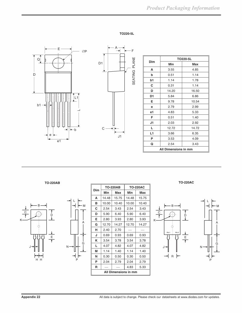
Appendix 22 All data is subject to change. Please check our datasheets at www.diodes.com for updates.
Product Packaging Information
AF
C
SE
AT
ING
PL
AN
E
D
E
L
b
e1
b1
P
D1Q
L1
J1e
DimTO220-5L
Min Max
A 3.55 4.85
b 0.51 1.14
b1 1.14 1.78
C 0.31 1.14
D 14.20 16.50
D1 5.84 6.86
E 9.78 10.54
e 2.79 2.99
e1 4.83 5.33
F 0.51 1.40
J1 2.03 2.92
L 12.72 14.72
L1 3.66 6.35
P 3.53 4.09
Q 2.54 3.43
All Dimensions in mm
TO220-5L
DimTO-220AB TO-220AC
Min Max Min Max
A 14.48 15.75 14.48 15.75
B 10.00 10.40 10.00 10.40
C 2.54 3.43 2.54 3.43
D 5.90 6.40 5.90 6.40
E 2.80 3.93 2.80 3.93
G 12.70 14.27 12.70 14.27
H 2.40 2.70
J 0.69 0.93 0.69 0.93
K 3.54 3.78 3.54 3.78
L 4.07 4.82 4.07 4.82
M 1.14 1.40 1.14 1.40
N 0.30 0.50 0.30 0.50
P 2.04 2.79 2.04 2.79
R 4.83 5.33
All Dimensions in mm
TO-220AB
L
M
A
N
P
D
E
K
C
B
JG
H H
L
M
A
N
P
D
E
K
C
B
JG
R
Pin 1 Pin 2
TO-220AC

All data is subject to change. Please check our datasheets at www.diodes.com for updates. Appendix 23
Product Packaging Information
A
B
D
E
G
G
C
+
-
+ -
WOG
Dim Min Max
A 8.84 9.86
B 4.00 4.60
C 27.90
D 25.40
E 0.71 0.81
G 4.60 5.60
All Dimensions in mm
D
b
e
E L
b1
A
A1
DimTO92-3L
Min Max
A 3.302 3.810
A1 1.016
b 0.330 0.432
b1 0.406 0.506
D 4.445 4.669
E 4.445 4.699
L 13.00 15.50
e 1.150 1.390
All Dimensions in mm
TO92-3L
TO-3P / TO-247
Dim Min Max
A 1.9 2.1
B 4.85 5.15
C 20.3 21.75
D 19.60 20.1
E 2.2 2.6
G 0.51 0.76
H 15.45 16.25
J 1.93 2.18
K 2.9 3.2
L 3.78 4.38
M 5.2 5.7
N 1.0 1.4
P 1.8 2.2
Q 2.8 3.2
S 4.4 Typ.
All Dimensions in mm
A
B
E
G
J
L
M
N
P Q
K
S
M
H
D
C
TO-3P / TO-247
WOG

Product Packaging Information
Appendix 24 All data is subject to change. Please check our datasheets at www.diodes.com for updates.
SUGGESTED PAD LAYOUT
Based on IPC-7351A
ALL DIMENSIONS ARE NOMINAL VALUES SHOWN IN MILLIMETERSNote: The suggested land pattern dimensions have been provided for reference only, as actual pad layouts may vary depending onapplication. These numbers may be modified based on user equipment capability or fabrication criteria. A more robust pattern may be desiredfor wave soldering and is calculated by adding 0.2 mm to the ‘Z’ dimension. For further information, please reference document IPC-7351A,Naming Convention for Standard SMT Land Patterns, and for International grid details, please see document IEC, Publication 97.
Z
X
C
GY
Figure 1Dimensions
DFN1006-2 /DFN1006H4-2
MiniMELF MELF SOD-323 SOD-123 SOD-523 SMA SMB SMC
Z 1.1 4.8 6.3 3.75 4.9 2.3 6.5 6.7 9.3
G 0.3 2.1 3.3 1.05 2.5 1.1 1.5 1.8 4.4
X 0.7 1.7 2.7 0.65 0.7 0.8 1.7 2.3 3.3
Y 0.4 1.3 1.5 1.35 1.2 0.6 2.5 2.5 2.5
C 0.7 3.5 4.8 2.40 3.7 1.7 4.0 4.3 6.8
Fig. 1
Y
C
G1
G2X
X1
Z
Fig. 2
Figure 2Dimensions
DFN1006-3 / DFN1006H4-3
Z 1.1
G1 0.3
G2 0.2
X 0.7
X1 0.25
Y 0.4
C 0.7
C
Y
X1
Z
G1
X
X2
G2
Figure 3Dimensions
DFN1411-3
Z 1.38
G1 0.15
G2 0.15
X 0.95
X1 0.75
X2 0.40
Y 0.75
C 0.76
Fig. 3

G1
Y2
Y1
CX1
X2 G2a
Fig. 6
All data is subject to change. Please check our datasheets at www.diodes.com for updates. Appendix 25
Product Packaging Information
ALL DIMENSIONS ARE NOMINAL VALUES SHOWN IN MILLIMETERSNote: The suggested land pattern dimensions have been provided for reference only, as actual pad layouts may vary depending onapplication. These numbers may be modified based on user equipment capability or fabrication criteria. A more robust pattern may be desiredfor wave soldering and is calculated by adding 0.2 mm to the ‘Z’ dimension. For further information, please reference document IPC-7351A,Naming Convention for Standard SMT Land Patterns, and for International grid details, please see document IEC, Publication 97.
Fig. 5
Figure 5Dimensions
DFN1616-6
Z 1.3
G 0.175
X1 0.50
X2 0.525
Y 0.30
X1
G
X2
Z
CY
b
G3 a
G2X2
Y2
Y1
G1
X1
Fig. 4
Figure 4Dimensions
DFN1612-6 DFN1310H4-6
G1 0.15 0.16
G2 0.175 0.17
G3 0.15 0.15
X1 0.60 0.52
X2 0.25 0.20
Y1 0.65 0.52
Y2 0.45 0.375
a 0.10 0.09
b 0.15 0.06
Figure 6Dimensions
DFN1616-8
G1 0.15
G2 0.20
X1 0.65
X2 0.25
Y1 1.25
Y2 0.50
C 0.40
a 0.10
Fig. 7
Figure 7Dimensions
DFN2020-6
Z 1.67
G 0.15
X1 0.90
X2 0.45
Y 0.37
C 0.65
G
G
Y C
Z
Y
X2
X1

Appendix 26 All data is subject to change. Please check our datasheets at www.diodes.com for updates.
Product Packaging Information
Note: The suggested land pattern dimensions have been provided for reference only, as actual pad layouts may vary depending onapplication. These numbers may be modified based on user equipment capability or fabrication criteria. A more robust pattern may be desiredfor wave soldering and is calculated by adding 0.2 mm to the ‘Z’ dimension. For further information, please reference document IPC-7351A,Naming Convention for Standard SMT Land Patterns, and for International grid details, please see document IEC, Publication 97.
ALL DIMENSIONS ARE NOMINAL VALUES SHOWN IN MILLIMETERS
Fig. 9
Figure 9Dimensions
DFN3030-8
Z 2.59
G 0.11
X1 2.49
X2 0.65
Y 0.39
C 0.65
Z
G
X1
X2
Y C
Fig. 11
X
C1
C2
Y
Figure 11Dimensions
MSOP-10L
X 0.20
Y 0.8
C1 4.2
C2 0.50
Fig. 10
X
C
Y
Z
Figure 10Dimensions
DF-S MiniDIP
Z 10.26 6.91
X 1.2 0.76
Y 1.52 0.58
C 5.2 2.67
Fig. 8
G
G
Y C
Z
Y1
X2
X1
G1
Figure 8Dimensions
DFN2020B-6
Z 1.67
G 0.20
G1 0.40
X1 1.0
X2 0.45
Y 0.37
Y1 0.70
C 0.65

X1 G X2
Y2 Y1
All data is subject to change. Please check our datasheets at www.diodes.com for updates. Appendix 27
Product Packaging Information
Note: The suggested land pattern dimensions have been provided for reference only, as actual pad layouts may vary depending onapplication. These numbers may be modified based on user equipment capability or fabrication criteria. A more robust pattern may be desiredfor wave soldering and is calculated by adding 0.2 mm to the ‘Z’ dimension. For further information, please reference document IPC-7351A,Naming Convention for Standard SMT Land Patterns, and for International grid details, please see document IEC, Publication 97.
ALL DIMENSIONS ARE NOMINAL VALUES SHOWN IN MILLIMETERS
Fig. 14
ZC
X2E1
X1
Y1Y2
Figure 13Dimensions
PowerDI123 PowerDI323
G 1.0 0.5
X1 2.2 2.0
X2 0.9 0.8
Y1 1.4 0.8
Y2 1.4 1.1
X
C1
C2
Y
Figure 15Dimensions
SOP-14L
X 0.41
Y 1.0
C1 5.1
C2 1.27
Fig. 15
Fig. 13
Figure 14Dimensions
PowerDI5
Z 6.6
X1 1.4
X2 3.6
Y1 0.8
Y2 4.7
C 3.87
E1 0.9
Fig. 12
X
C1
C2
Y
Figure 12Dimensions
MSOP-8L
X 0.32
Y 0.8
C1 4.2
C2 0.65

Appendix 28 All data is subject to change. Please check our datasheets at www.diodes.com for updates.
Product Packaging Information
Note: The suggested land pattern dimensions have been provided for reference only, as actual pad layouts may vary depending onapplication. These numbers may be modified based on user equipment capability or fabrication criteria. A more robust pattern may be desiredfor wave soldering and is calculated by adding 0.2 mm to the ‘Z’ dimension. For further information, please reference document IPC-7351A,Naming Convention for Standard SMT Land Patterns, and for International grid details, please see document IEC, Publication 97.
ALL DIMENSIONS ARE NOMINAL VALUES SHOWN IN MILLIMETERS
Fig. 17
Figure 17Dimensions
SOP-8L
X 0.41
Y 1.0
C1 5.1
C2 1.27
X
C1
C2
Y
X1 X2
GZ
Y
C
XX2
Fig. 18
Figure 18Dimensions
SOT-143
Z 2.70
G 1.30
X 2.50
X1 1.0
X2 0.60
Y 0.70
C 2.0
Figure 19Dimensions
SOT-223
X1 3.3
X2 1.2
Y1 1.6
Y2 1.6
C1 6.4
C2 2.3
Fig. 19
X2
C1
C2
X1
Y2
Y1
X
C1
C2
Y
Figure 16Dimensions
SOP-16L
X 0.41
Y 1.0
C1 5.1
C2 1.27
Fig. 16

All data is subject to change. Please check our datasheets at www.diodes.com for updates. Appendix 29
Product Packaging Information
Note: The suggested land pattern dimensions have been provided for reference only, as actual pad layouts may vary depending onapplication. These numbers may be modified based on user equipment capability or fabrication criteria. A more robust pattern may be desiredfor wave soldering and is calculated by adding 0.2 mm to the ‘Z’ dimension. For further information, please reference document IPC-7351A,Naming Convention for Standard SMT Land Patterns, and for International grid details, please see document IEC, Publication 97.
ALL DIMENSIONS ARE NOMINAL VALUES SHOWN IN MILLIMETERS
Y1
X3
X1
Y3Y2
X2
C
Y4
Figure 23Dimensions
SOT89-5L
X1 1.7
X2 0.55
X3 0.4
Y1 4.6
Y2 1.2
Y3 0.5
Y4 1.1
C 3.0
Fig. 23
Figure 22Dimensions
SOT89-3L
X1 1.7
X2 0.9
X3 0.4
Y1 2.7
Y2 1.3
Y3 1.9
C 3.0
Y1
X3
X1
Y3Y2
X2
C
Fig. 22
Fig. 21
X
Z
Omit this padfor SOT-353 and SOT-25
Y
C1G
C2C2
Figure 21Dimensions
SOT-363 /SOT-353
SOT-26 / SC-74R /SOT-25
SOT-563
Z 2.5 3.20 2.2
G 1.3 1.60 1.2
X 0.42 0.55 0.375
Y 0.6 0.80 0.5
C1 1.9 2.40 1.7
C2 0.65 0.95 0.5
X E
Y
CZ
Fig. 20
Figure 20Dimensions
SOT-523 SOT-323 SOT-23 SC-59
Z 1.8 2.8 2.9 3.4
X 0.4 0.7 0.8 0.8
Y 0.51 0.9 0.9 1.0
C 1.3 1.9 2.0 2.4
E 0.7 1.0 1.35 1.35

Appendix 30 All data is subject to change. Please check our datasheets at www.diodes.com for updates.
Product Packaging Information
Note: The suggested land pattern dimensions have been provided for reference only, as actual pad layouts may vary depending onapplication. These numbers may be modified based on user equipment capability or fabrication criteria. A more robust pattern may be desiredfor wave soldering and is calculated by adding 0.2 mm to the ‘Z’ dimension. For further information, please reference document IPC-7351A,Naming Convention for Standard SMT Land Patterns, and for International grid details, please see document IEC, Publication 97.
ALL DIMENSIONS ARE NOMINAL VALUES SHOWN IN MILLIMETERS
X
C1
C2
Y
Fig. 27
Fig. 25
Y2
Y
Y1
X
C2
C1
X1
Figure 25Dimensions
TO252-5L
X 5.6
X1 0.6
Y 11.0
Y1 5.6
Y2 2.0
C1 7.2
C2 1.27
Figure 26Dimensions
TO263-5L
X 10.9
X1 1.05
Y 15.7
Y1 9.1
Y2 2.5
C 1.7
Fig. 26
Y2
Y
Y1
X
CX1
Figure 27Dimensions
TSSOP-14L
X 0.45
Y 1.45
C1 5.9
C2 0.65
X2
CZ
X1
Y1
E1
Y2
Figure 24Dimensions
TO252-3L /DPAK
TO263-3L /D2PAK
Z 11.6 16.9
X1 1.5 1.1
X2 7.0 10.8
Y1 2.5 3.5
Y2 7.0 11.4
C 6.9 9.5
E1 2.3 2.5
Fig. 24

Product Packaging Information
MINIMUM PACKING QUANTITY
PACKAGETYPE
BulkTube Quantity
7" Tape and Reel 13" Tape and Reel
Quantity Part Number Suffix Quantity Part NumberSuffix
DFN Series NA 3K -7 10K -13
DF-S 50 NA NA 1.5K -T
D2PAK NA NA NA 800 -T
D-PAK NA NA NA 2500 -13
MELF NA NA -7 5K -13
MiniDIP NA NA NA 3K -T
MiniMELF NA 2.5K -7 10K -13
MSOP-8L 80 NA NA 2.5K -13
MSOP-10L 80 NA NA 2.5K -13
PowerDI5 NA NA NA 5K -13
PowerDI123 / PowerDI323 NA 3K -7 10K -13
SC-59 NA 3K -7 10K -13
SMA NA NA NA 5K -13
SMB NA NA NA 3K -13
SMC NA NA NA 3K -13
SOD-123 / 323 / 523* NA 3K* -7* 10K -13
SON-6L NA 3K -7 NA NA
SOP-8L 100 NA NA 2.5K -13
SOP-14L 56 NA NA 2.5K -13
SOP-16L 50 NA NA 2.5K -13
SOT-23 / 323 / 353 / 363 / 523 NA 3K -7 10K -13
SOT-25 / -26 / SC-74R / SOT-563 NA 3K -7 10K -13
SOT89-3L / SOT89-5L NA -7 2.5K -13
SOT-143 NA 3K -7 10K -13
SOT-223 75 NA NA 2.5K -13
SOT-553 NA 3K -7 NA NA
TO-252-3L / TO-252-5L 80 NA NA 2.5K -13
TO-263-3L / TO-263-5L 50 NA NA 800 -13
TSSOP-14L 96 NA NA 2.5K -13
Notes: 1. Package quantities given are for minimum packaging quantity only, not minimum order quantity.For minimum order quantity, please contact the Sales Department.
2. No mixed date codes or partial quantity (less than minimum packaging quantity) per packaging is allowed.3. In no case shall there be two or more consecutive components missing from any reel for any reason.
*SOD-523 available in 6K quantity on 7-inch reel, part number suffix "-76K".
All data is subject to change. Please check our datasheets at www.diodes.com for updates. Appendix 31
SURFACE MOUNT (SMD) PACKAGING
Bulk, Reel and Carrier Tape Specifications

Appendix 32 All data is subject to change. Please check our datasheets at www.diodes.com for updates.
Product Packaging Information
SOT-23 / 323 / 523 SOT-353 / SOT-25
SOD-123 / 323 / 523 1
7.7 7.78.3 8.3
3.90 3.904.10 4.10
1.55 1.551.65 1.65
3.90
3.90
4.10
4.10
1.55
1.50
1.65
1.60
7.7
7.7
8.3
8.3
SMA
11.712.3
3.904.10
1.551.65
MELF
MiniDIP
11.712.3
3.904.10
1.551.65
SMB
11.7
11.7
12.3
12.3
3.90
3.90
4.10
4.10
1.55
1.55
1.65
1.65
KXX
+ +++
KXXKXXKXXKXX KXX KXX
8mm
12mm
SC-74 / SOT-26 / SOT-363 / SOT-563
SC-74R
7.78.3
3.90
3.90
4.10
4.10
1.55
1.55
1.65
1.65
KXX KXX
KXX
KXXKXXKXXKXX KXX KXX
AsymmetricalProduct
PowerDI 123 / 323
SC-74 / SOT-26 / SOT-363 / SOT-563
7.78.3
KXXKXX KXXKXX KXXKXX KXX KXX KXXKXX KXX KXX KXX
KXX
KXX
KXX
3.904.10
1.551.65
Symmetrical product(No pin 1 indicator).
7.98.3
DFN
For DFN details - refer tospecific datasheet.
++ + +
Direction of unreeling
1 SOD-523 has alternating empty cavities as indicated below.
Tape Dimensions and Orientation: (Dimensions in mm)For Part Marking, Refer to Datasheet

All data is subject to change. Please check our datasheets at www.diodes.com for updates. Appendix 33
Product Packaging Information
Tape Dimensions and Orientation: (Dimensions in mm)For Part Marking, Refer to Datasheet
SOT-223
11.712.3
12mm (Continued)
PIN 1
SOT89-5L
SOT89-3L
SOT89-5L (reverse taping)
SOP-8L TSSOP-14L
11.7 11.7
11.7
11.7
12.3 12.3
12.3
12.3
11.712.3
5.4/5.6 5.4/5.6
1.45/1.55 1.45/1.55PIN 1 3.9/4.1 3.9/4.17.9/8.1 7.9/8.1
PIN 1
PIN 1
PIN 13.9/4.1
7.9/8.1
1.45/1.55
1.45/1.55
1.45/1.55
7.9/8.1
7.9/8.1
3.9/4.1
3.9/4.1
5.4/5.6
5.4/5.6
Top Mark
Top Mark
1111
5555
1
5
1.45/1.553.9/4.1 7.9/8.1
5.4/5.6
Direction of feed

Product Packaging Information
Tape Dimensions and Orientation: (Dimensions in mm)For Part Marking, Refer to Datasheet
Appendix 34 All data is subject to change. Please check our datasheets at www.diodes.com for updates.
15.716.3
3.904.10
1.551.65
DF-S
SMC
16mm
15.716.3
3.904.10
1.551.65
+ + +
D2PAK
23.724.3
3.904.10
1.55
15.9
1.65
24mm
16.1
TO263
1.45/1.55
11.4/11.6
23.7/24.3
15.9/16.13.9/4.1PIN 1
15.7
15.7
16.3
16.3
TO252 / D-PAK
1.45/1.557.9/8.1 3.9/4.1
15.7/16.37.4/7.6PIN 1
SOP-14L
SOP-16L
3.9/4.1
3.9/4.1
7.9/8.1
7.9/8.1
PowerDI 5
15.716.3
3.90
+ +
4.101.551.65
Direction of feed

Product Packaging Information
8, 12, 16, 24mm EMBOSSED TAPE DIMENSIONS IN mm
Tape Size D E Po tmax Ao Bo KoConstant
Dimensions8, 12, 16, 24mm 1.55 +0.10
-0.01.75 0.10 4.0 0.10 0.400 See Note 1
Tape Size B1max
D1min
F Kmax
P2 Rmin
W Product Type
8mm 4.5 1.0 3.5 0.05 2.4 2.0 0.05 25 8.0 0.30
DFN Series, SOT-23, SOT-25,SOT-26, SOT-143, SOT-323,
SOT-353, SOT-363, SOT-523,SOT-563, MiniMELF,
PowerDI123, PowerDI323,SOD-123, SOD-323, SOD-523,
SC-59, SC-74R
12mm 8.2 1.5 5.5 0.05 4.5 2.0 0.05 30 12.0 0.30 MELF, SMA, SMB, miniDIPSOP-8L, SOT-223, SOT-89
16mm 12.1
1.41.51.51.5
7.5 0.107.5 0.107.5 0.107.5 0.05
2.253.293.702.89
2.0 0.102.0 0.104.0 0.102.0 0.05
40
16.0 0.3016.0 0.3016.0 0.3016.0 0.2
SOP-14L, SOP-16LSMCDF-S
PowerDI5, TO-252
24mm 20.1 1.5 11.5 0.10 6.5 2.0 0.10 50 24.0 0.30 D2PAK, TO-263
Tape SizeP
2.0 ± 0.05 4.0 ± 0.10 8.0 ± 0.10 12.0 ± 0.10 16.0 ± 0.10
8mm SOD-523-76K See above (exceptSOD-523-76K) — — —
12mm — SMA, MELFSMB, miniDIP,
SOP-8L, SOT-89L,SOT-223
— —
16mm — —SMC, D-PAK,
SOP-14L, SOP-16LPowerDI5
DF-S —
24mm — — — — D2PAK
Notes: 1. A0 B0 K0 are determined by component size. The clearance between the component and the cavity must be within 0.05mm min.to 0.50mm max. for 8mm tape, 0.05mm min. to 0.65 mm max. for 12mm tape and 0.15mm min. to 0.90mm max. for 16mm tape.
All data is subject to change. Please check our datasheets at www.diodes.com for updates. Appendix 35
See Note 1and Table
P
Dt
K
TopCoverTape
See Note 1and Table
For Machine Reference OnlyIncluding Draft and RadiiConcentric Around B0
B0
D1For components2.0mm x 1.2mmand larger
P0
P2
A0
E
F W
10 pitchescumulativetolerance ontape±0.2
User Direction of Feed
B1 K0
EMBOSSED CARRIER TAPE SPECIFICATIONS
(8, 12, 16, 24mm Tape)

Top cover
tape thickness
0.10mm Max.
Embossed
Carrier
Cavity
100mm
1mm Max.
Camber (Top View)
250mm
1mm Max.
Tape
Allowable camber to be 1.0mm/100mm non-accumulative over 250mm
R Min.
Bending Radius
See Note 2
Directionof feed
Product Packaging Information
2. Add 0.05mm min. to 1.00mm min. for 24mm tape and larger. The component cannot rotate more than 20 within the determinedcavity, see sketch next page.
3. Tape and components shall pass around radius ‘R’ without damage.
Appendix 36 All data is subject to change. Please check our datasheets at www.diodes.com for updates.
20°
Maximum component rotation
Typicalcomponent cavitycenterline
Typicalcomponentcenterline

Product Packaging Information
SURFACE MOUNT CARRIER TAPE SPECIFICATIONSSURFACE MOUNT REEL SPECIFICATIONS
(All Dimensions in mm)
Tape Size AMax
B*Max C D*
MaxN
Min G TMax
8mm 330 1.5 13.0 0.20 20.2 50 8.4 +1.5- 0.0 14.4
12mm 330 1.5 13.0 0.20 20.2 50 12.4 +2.0- 0.0 18.4
16mm 330 1.5 13.0 0.20 20.2 50 16.4 +2.0- 0.0 22.4
24mm 330 1.5 13.0 0.20 20.2 50 24.4 +2.0- 0.0 30.4
Tape Leader and Trailer
All data is subject to change. Please check our datasheets at www.diodes.com for updates. Appendix 37
A
B*
D*
Full Radius
T
C
N
G (measured at hub)
*Drive spokes optional. If used,dimensions with asterisks apply.
No Components* ComponentsMin. 160mm Min. 390mm
User Direction of FeedTopCoverTape
End
Start
Min. 160mmCarrier tape sealedwith cover tape
12
Notes: 1. There shall be a leader of 230mm [9.05] minimum which may consist of carrier and/or cover tape or a start tape followed by aminimum of 160mm [6.30] of empty carrier tape sealed with cover tape.
2. There shall be a trailer of 160mm [6.30] minimum of empty carrier tape sealed with cover tape. The entire carrier tape mustrelease from the reel hub as the last portion of the tape unwinds from the reel without damage to the carrier tape and theremaining components in the cavities.

THROUGH-HOLE PACKAGING
Bulk, Reels, Ammo Packs & Taping Specifications
MINIMUM PACKAGING QUANTITY
MINIMUM PACKING QUANTITY
Device Type
Available Packaging
Bulk 13" Tape & Reel Ammo Pack
Quantity per Box Quantity per Tube Quantity per Tray Quantity per Reel Quantity per Box
5KP 500 500 / 700*
5W 1K 3K
5KW 1K
A-405 1K 5K 3K
DF-M 5K 50
DO-15 500 / 800 / 1K* 4K 2K
DO-201 1K 1K / 1.2K*
DO-201AD 500 / 1K* 1.2K
DO-35 500 10K 5K/10K*
DO-41 500/1K* 5K 3K/5K*
GBJ 700 15
GBPC/W 100
GBU 1K 20
KBJ 1K 20
KBP 3.5K 35
KBPC/W 100
MB/W 100
MP/W 100
PBL 100
PBPC-3 200
PBPC-8 150
PBU 100
PDIP-8L 5040 60
R-6 200 / 500* 500 / 700*
SIP-3L 25K 4K
SIP-4L 25K
SIP-5L 25K
Appendix 38 All data is subject to change. Please check our datasheets at www.diodes.com for updates.
Product Packaging Information

Product Packaging Information
MINIMUM PACKING QUANTITY
Device Type
Available Packaging
Bulk 13" Tape & Reel Ammo Pack
Quantity per Box Quantity per Tube Quantity per Tray Quantity per Reel Quantity per Box
T1 1K 5K 3K
TO-220AB / AC / ITO220AB 2K 50
TO220-5L 80 2.5K
TO3P 1.2K 30
TO92 1K / 2.5K / 5K* 2K
WOG 1K
* Quantity varies by Part Number.
Notes: 1. Package quantities are given for minimum packaging quality only, not minimum order quantity. For minimum orderquantity, please consult the Sales Department.
2. No mixed date codes or partial quantity (less than minimum packaging quantity) per packaging is allowed.3. In no case shall there be two or more consecutive components missing from any reel for any reason.
All data is subject to change. Please check our datasheets at www.diodes.com for updates. Appendix 39

Appendix 40 All data is subject to change. Please check our datasheets at www.diodes.com for updates.
PRODUCT LABEL SPECIFICATION
Label Placement/Dimensions, Definitions & Part Designation
STANDARD PRODUCT LABEL(Discrete Product)
Leading Quiet Zone Trailing Quiet Zone
Scanned Data
BAT54C-7
30000
0129-B711759.K1
4.00”
1.50”
MADE IN (Country)
Optional Feature FieldP/N: BAT54C-7
QTY: 30000
D/C-LOT: 0129-B711759.K1
Fig. 1 Standard Label for SnPb Finish, non RoHS CompliantExample: BAT54C-7
Ro
HS
Co
mp
lian
t
Pb
MSL1
ex
Fig. 2 Standard Label for Sn Finish, RoHS CompliantContains Exempt Lead (Pb)Example S1G-13-F
Ro
HS
Co
mp
lian
t
Pb
Pb-free
MSL1
ex
Fig. 3 Standard Label for Completely Lead Free, RoHS Compliant ProductProduct is not "Green" (Contains Sb, Halogens, etc.)Example BAT54C-7-F
Product Packaging Information

Product Packaging Information
All data is subject to change. Please check our datasheets at www.diodes.com for updates. Appendix 41
STANDARD PRODUCT LABEL(Discrete Product) (Continued)
Ro
HS
Co
mp
lian
t
MSL1
V
Pb-free, Green
ex
Ro
HS
Co
mp
lian
t
Pb
MSL1
e3
P/N: 1N5254B-T
D/C - LOT: 0504 - 200504CN81
QTY: 10000
Fig. 5 Supplemental Label added at Distribution point (primarily glass packaged product)
4.00”
1.50”
Fig. 6
STANDARD PRODUCT LABEL(Analog Product)
4.00”
2.00”
Fig. 7
Fig. 4 Standard Label for Completely Lead Free, "Green", RoHS Compliant ProductProduct contains no Pb, Sb, BrExample BAT54V-7

Product Packaging Information
Appendix 42 All data is subject to change. Please check our datasheets at www.diodes.com for updates.
STANDARD PRODUCT LABEL(Analog Product) (Continued)
H1
H2
W
Fig. 8 Standard Diodes Logo Dimension
STANDARD PRODUCT LABEL(Discrete and Analog Product)
Title Word "DIODES" (only) Logo with "INCORPORATED"
Color Palette1 Blue PMS# 294 PMS# 294 (Word "DIODES" in Blue)/PMS# 418 (Word "INCORPORATED" in Grey)
4 Color ProcessEquivalents (%) C-100, M-56, Y-0, K-18 "DIODES" C-100, M-56, Y-0, K-18
"INCORPORATED" C-0, M-0, Y-30, K-79
Width/Height Ratio2 W/H1 = 5.12 W/H2 = 4.14
PRODUCT LABEL TITLE FIELD FORMAT AND DEFINITION
Title Max Length / Format Definition
P/N 16 Digit / Alphanumeric Part number consists of generic device number followed by packagingcode, which is assigned by Diodes, Inc.
QTY 6 Digit / Alphanumeric Unit quantity within the packaging or box/carton.
MADE IN (Country) Maintain Trailing Quiet Zone In (Country) bracket, fill in Country of Origin.
D/C-LOTDC - 4 Digit (fixed) / Numeric(YYWW)LOT - 13 Digit / Alphanumericmaximum (Shall consist of factorycode as suffix with a separator ".")
Traceability number (in the format of Date Code - Lot Number) assignedby the factory to identify a unique group of entities (which shall contain orbe able to track information of wafer, operator, equipment, shift and etc.Individual manufacturing plant format is acceptable).
NOTE 16 Digit / Alphanumeric PO# or Internal work order information
Graphical Icon Lead Free Finish
Graphical Icon Totally Lead Free Product
Graphical Icon Totally Green and Lead Free Product
Graphical Icon2nd Level Interconnect Indicatorx = 3 for Snx = 4 for Precious Metal (NiPd)
RoHS Compliant Product Statement Indicates product is RoHS Compliant as of production date
MSLx Product Statement x = Actual MSL (Moisture Sensitivity Level)
Pb
Pb
Pb-free
Pb-free, Green
ex

Product Packaging Information
Outer Carton Specifications
OUTER CARTON
PRODUCT HEIGHT (H) WIDTH (W) LENGTH (L)
DESCRIPTION inches mm inches mm inches mm
5KP, 5KW, 5W, DO-15, DO-41, DO-201,DO-201AD, R6, T1 (Tape and Reel form) 13.38 340 13.38 340 13.38 340
D2PAK 14.25 360 13.75 350 13.75 350
DF-M 12.50 315 13.00 330 19.75 500
DFN-Series, SOD-123, SOD-323, SOD-523,SOT-23, SOT-323, SOT-523, SC-59,SOT-353 / 363, SOT-25 / 26, SOT-563,PowerDI123, PowerDI323
9.50 241 17.25 438 17.25 438
DF-S 11.25 285 14.5 368 14.5 368
DO-15, DO-41, A-405 (Bulk form) 9.88 250 8.25 210 17.75 450
DO-201 / DO-201AD / R6 (Bulk form) 11.00 280 13.00 330 13.50 342
GBJ 10.38 265 9.06 230 20.50 520
KBPC, GBPC, MP, MB 8.25 210 11.38 290 13.00 330
KBJ 9.63 245 9.06 230 22.44 570
KBP 11.25 285 10.38 265 22.44 570
MSOP-8L / MSOP-10L (Bulk form) 8.58 218 13.94 354 25.08 637
MSOP-8L / MSOP-10L (Tape and Reel form) 14.88 378 15.55 395 17.32 440
PBL, RS4 12.08 315 11.38 290 13.00 330
PBP 11.75 300 13.00 330 13.00 330
PBPC-3/6A 11.75 300 13.00 330 13.00 330
PBPC-8/10A 12.25 310 8.25 210 17.75 450
PBU, RS6 6.5 178 13.5 343 13.5 343
PDIP-8L 8.58 218 15.55 395 25.08 637
PowerDI5 11.50 292 13.50 343 13.50 343
SIP-3L (Bulk form) 8.58 218 15.55 395 25.08 637
SIP-3L (Ammo pack) 14.88 378 13.94 354 17.32 440
SIP-4L 8.58 218 15.55 395 25.08 637
SIP-5L 8.58 218 15.55 395 25.08 637
SMA, SMB, SMC 13.38 340 13.75 350 13.38 340
SOP-8L / SOP-14L / SOP-16L (Bulk form) 8.58 218 15.55 395 25.08 637
SOP-8L / SOP-14L / SOP-16L(Tape and Reel form) 14.88 378 13.94 354 17.32 440
All data is subject to change. Please check our datasheets at www.diodes.com for updates. Appendix 43
PRODUCT CARTON SPECIFICATIONS
Outer/Inner Cartons, Designs

Outer Carton Specifications (Continued)
OUTER CARTON
PRODUCT HEIGHT (H) WIDTH (W) LENGTH (L)
DESCRIPTION inches mm inches mm inches mm
SOT89-3L / SOT89-5L 14.88 378 13.94 354 17.32 440
SOT-223 (Bulk form) 8.58 218 15.55 395 25.08 637
SOT-223 (Tape and Reel form) 14.88 378 13.94 354 17.32 440
TO220AB / TO220AC / ITO220(AB) 9.00 229 7.75 197 22.88 581
TO220-3L / TO220-5L 8.58 218 15.55 395 25.08 637
TO252-3L / TO252-5L (Bulk form) 14.88 378 13.94 354 17.32 440
TO252-3L / TO252-5L (Tape and Reel form) 8.58 218 15.55 395 25.08 637
TO263-3L / TO263-5L (Bulk form) 14.88 378 13.94 354 17.32 440
TO263-3L / TO263-5L (Tape and Reel form) 8.58 218 15.55 395 25.08 637
TO-3P 10.50 265 9.00 230 22.63 575
TO-92 (Bulk form) 8.58 218 15.55 395 25.08 637
TO-92 (Ammo pack) 14.88 378 13.94 354 17.32 440
TSSOP-14L (Bulk form) 14.88 378 13.94 354 17.32 440
TSSOP-14L (Tape and Reel form) 8.58 218 15.55 395 25.08 637
WOG 11.38 290 13.12 333 14.25 363
1. All cartons must meet Rule 41 of the Uniform Freight Classification.2. All cartons must not exceed 35 lbs. on weight.3. All carton printing must be from supplied camera ready art (refer to figures 1-4 of this specification).4. Printed carton color must be Black.5. Dimension tolerance is 0.20” or 5.0mm.6. General carton design types A and B must be followed. Due to varying carton shapes, it may be necessary to
scale or reposition design elements to match general format.7. Inner and Outer carton must be affixed with Bar Code Labels as outlined in Diodes' Quality Document QP-086.8. Carton samples or layout must be submitted to Quality Assurance prior to first article shipment.9. Product Packaging will periodically be inspected for compliance to this specification.
Appendix 44 All data is subject to change. Please check our datasheets at www.diodes.com for updates.
Product Packaging Information

Product Packaging Information
All data is subject to change. Please check our datasheets at www.diodes.com for updates. Appendix 45
Inner Carton Specifications
INNER CARTONMAXIMUMQUANTITYPRODUCT HEIGHT (H) WIDTH (W) LENGTH (L)
DESCRIPTION inches mm inches mm inches mm
D2PAK 1.50 38 13.50 343 13.38 340 800
DF-M / DF-S (Tube) 6.00 152 6.50 165 19.50 495 5,000
DFN-Series, SOD-123, SOD-323, SOD-523,SOT-23, SOT-323, SOT-523, SC-59,SOT-353 / 363, SOT-25 / 26, SOT-563,PowerDI123, PowerDI323
8.00 203 8.13 207 8.13 206 45,000
DF-S (Tape) 1.13 29 13.25 337 13.25 337 1,500
DO-15, DO-41, A-405 (Bulk form) 0.90 23 3.38 86 7.88 200 1,000
DO-201AD, R6 (Bulk form) 1.50 38 3.00 76 12.00 305 500
DO-35 3.75 95 14.88 378 14.50 368 10,000
DPAK 1.50 38 13.50 343 13.38 340 5,000
GBJ 7.36 187 8.00 203 20.00 508 600
KBJ 5.00 127 8.25 210 22.00 559 1,000
KBP 5.50 140 9.50 241 22.00 559 3,500
MELF 1.50 38 13.25 337 13.25 337 10,000
MiniDIP 1.50 38 13.25 337 13.25 337 6,000
MiniMELF 3.00 76 7.25 184 7.25 184 12,500
MSOP-8L / MSOP-10L (Bulk form) 3.82 97 7.36 187 24.60 625 16,000
MSOP-8L / MSOP-10L (Tape and Reel form) 1.97 50 13.35 339 13.90 353 2,500
PDIP-8L 3.82 97 7.36 187 24.60 625 16,000
SIP-3L / SIP-4L / SIP-5L (Bulk form) 3.82 97 7.36 187 24.60 625 25,000
SIP-3L (Ammo pack) 1.57 40 7.87 200 13.00 330 4,000
SMA 1.63 41 13.50 343 13.38 340 10,000
SMB 1.63 41 13.50 343 13.38 340 6,000
SMC 2.13 54 13.50 343 13.38 340 6,000
SOP-8L (Bulk form) 3.82 97 7.36 187 24.60 625 44,000
SOP-8L / SOP-14L / SOP-16L (Tape and Reelform) 1.97 50 13.35 339 13.90 353 2500
SOP-14L (Bulk form) 3.82 97 7.36 187 24.60 625 24,640
SOP-16L (Bulk form) 3.82 97 7.36 187 24.60 625 22,000
SOT89-3L / SOT89-5L 1.97 50 13.35 339 13.90 353 2,500
SOT223 (Bulk form) 3.82 97 7.36 187 24.60 625 30,000
SOT223 (Tape and Reel form) 1.97 50 13.35 339 13.90 353 2,500
TO-220AB / TO-220AC / ITO-220AB 4.00 102 6.88 175 22.00 559 2,000
TO220-3L / TO220-5L 3.82 97 7.36 187 24.60 625 2,000
TO252-3L / TO252-5L (Bulk form) 1.97 50 13.35 339 13.90 353 10,800

Appendix A-46 All data is subject to change. Please check our datasheets at www.diodes.com for updates.
Product Packaging Information
INNER CARTONMAXIMUMQUANTITYPRODUCT HEIGHT (H) WIDTH (W) LENGTH (L)
DESCRIPTION inches mm inches mm inches mm
TO252-3L / TO252-5L (Tape and Reel form) 1.97 97 13.35 187 24.60 625 2,500
TO263-3L / TO263-5L (Bulk form) 1.97 50 13.35 339 13.90 353 2,000
TO263-3L / TO263-5L (Tape and Reel form) 3.82 97 7.36 187 24.60 625 800
TO-3P 5.00 127 8.00 203 21.50 546 5,000
TO-92 (Bulk form) 3.82 97 7.36 187 24.60 625 20,000
TO-92 (Ammo pack) 1.57 40 7.87 200 13.00 330 2,000
TSSOP-14L (Bulk form) 1.97 50 13.35 339 13.90 353 40,320
TSSOP-14L (Tape and Reel form) 3.82 97 7.36 187 24.60 625 2,500
WOG 3.25 83 6.88 175 10.00 254 1,000
1. All cartons must meet Rule 41 of the Uniform Freight Classification.2. Dimension tolerance is 0.20” or 5.0mm.3. Inner and Outer carton must be affixed with Bar Code Labels as outlined in Diodes' Quality Document QP-086.4. Product Packaging will periodically be inspected for compliance to this specification.

1.5KE10(C)A, 14-7 1N4003G, 20-2 1N5395S, 20-3 2DD1766Q, 15-4 AP1122, 3-21.5KE100(C)A, 14-7 1N4003GL, 20-1 1N5397, 20-3 2N7002, 17-2 AP1184, 3-21.5KE11(C)A, 14-7 1N4003L, 20-1 1N5397G, 20-3 2N7002DW, 17-2 AP1186, 3-21.5KE110(C)A, 14-7 1N4004, 20-2 1N5397S, 20-3 2N7002E, 17-2 AP1212H, 7-11.5KE12(C)A, 14-7 1N4004G, 20-2 1N5398, 20-3 2N7002K, 17-2 AP1212L, 7-11.5KE120(C)A, 14-7 1N4004GL, 20-1 1N5398G, 20-3 2N7002VAC, 17-1 AP130, 3-11.5KE13(C)A, 14-7 1N4004L, 20-1 1N5398S, 20-3 2N7002VC, 17-1 AP131, 3-11.5KE130(C)A, 14-7 1N4005, 20-2 1N5399, 20-3 2N7002W, 17-1 AP133, 3-11.5KE15(C)A, 14-7 1N4005G, 20-2 1N5399G, 20-3 2W005G, 21-2 AP139, 3-11.5KE150(C)A, 14-7 1N4005GL, 20-1 1N5399S, 20-3 2W01G, 21-2 AP1501, 2-11.5KE16(C)A, 14-7 1N4005L, 20-1 1N5400, 20-4 2W02G, 21-2 AP1501A, 2-11.5KE160(C)A, 14-7 1N4006, 20-2 1N5400G, 20-4 2W04G, 21-2 AP1506, 2-11.5KE170(C)A, 14-7 1N4006G, 20-2 1N5401, 20-4 2W06G, 21-2 AP1507, 2-11.5KE18(C)A, 14-7 1N4006GL, 20-1 1N5401G, 20-4 2W08G, 21-2 AP1509, 2-11.5KE180(C)A, 14-7 1N4006L, 20-1 1N5402, 20-4 2W10G, 21-2 AP1510, 2-11.5KE20(C)A, 14-7 1N4007, 20-2 1N5402G, 20-4 3.0SMCJ20A, 14-7 AP1511, 2-11.5KE200(C)A, 14-7 1N4007G, 20-2 1N5404, 20-4 3.0SMCJ22A, 14-7 AP1512, 2-11.5KE22(C)A, 14-7 1N4007GL, 20-1 1N5404G, 20-4 3.0SMCJ24A, 14-7 AP1512A, 2-11.5KE220(C)A, 14-7 1N4007L, 20-1 1N5406, 20-4 3.0SMCJ28A, 14-7 AP1513, 2-11.5KE24(C)A, 14-7 1N4148W, 12-3 1N5406G, 20-4 3.0SMCJ30A, 14-7 AP1520, 2-11.5KE250(C)A, 14-7 1N4148WS, 12-1 1N5407, 20-4 3.0SMCJ5.0A, 14-7 AP1530, 2-11.5KE27(C)A, 14-7 1N4148WT, 12-1 1N5407G, 20-4 3.0SMCJ58A, 14-7 AP1533, 2-11.5KE30(C)A, 14-7 1N4448HLP, 12-1 1N5408, 20-4 6A05, 20-5 AP1580, 2-11.5KE300(C)A, 14-7 1N4448HWS, 12-1 1N5408G, 20-4 6A1, 20-5 AP1601, 2-11.5KE33(C)A, 14-7 1N4448HWT, 12-1 1N5711W, 9-3 6A10, 20-5 AP1603, 2-11.5KE350(C)A, 14-7 1N4448W, 12-3 1N5711WS, 9-2 6A2, 20-5 AP1604A, 2-11.5KE36(C)A, 14-7 1N4448WS, 12-1 1N5817, 11-1 6A4, 20-5 AP1609, 2-11.5KE39(C)A, 14-7 1N4933, 19-3 1N5818, 11-1 6A6, 20-5 AP1624, 2-21.5KE400(C)A, 14-7 1N4933G, 19-3 1N5819, 11-1 6A8, 20-5 AP1635, 2-11.5KE43(C)A, 14-7 1N4933GL, 19-3 1N5819HW, 10-2 A AP1701/3, 5-11.5KE47(C)A, 14-7 1N4933L, 19-2 1N5820, 11-1 AH173, 8-1 AP1702/4, 5-11.5KE51(C)A, 14-7 1N4934, 19-3 1N5821, 11-1 AH175, 8-1 AP2001, 2-21.5KE56(C)A, 14-7 1N4934G, 19-3 1N5822, 11-1 AH1751, 8-1 AP2004, 2-21.5KE62(C)A, 14-7 1N4934GL, 19-3 1N6263W, 9-3 AH180, 8-2 AP2008, 2-21.5KE68(C)A, 14-7 1N4934L, 19-2 2A01, 20-3 AH1801, 8-2 AP2014, 2-21.5KE6V8(C)A, 14-7 1N4935, 19-3 2A01G, 20-3 AH1802, 8-2 AP2014A, 2-21.5KE75(C)A, 14-7 1N4935G, 19-3 2A02, 20-3 AH1803, 8-2 AP3152, 2-21.5KE7V5(C)A, 14-7 1N4935GL, 19-3 2A02G, 20-3 AH1884, 8-2 AP34063, 2-21.5KE82(C)A, 14-7 1N4935L, 19-2 2A03, 20-3 AH276Q, 8-1 AP358, 6-11.5KE8V2(C)A, 14-7 1N4936, 19-3 2A03G, 20-3 AH284, 8-2 AP393, 6-11.5KE91(C)A, 14-7 1N4936G, 19-3 2A04, 20-3 AH285, 8-2 AP431, 4-11.5KE9V1(C)A, 14-7 1N4936GL, 19-3 2A04G, 20-3 AH286, 8-3 AP431A, 4-110A01, 20-5 1N4936L, 19-2 2A05, 20-3 AH287, 8-3 AP432, 4-110A02, 20-5 1N4937, 19-3 2A05G, 20-3 AH288, 8-3 AP432A, 4-110A03, 20-5 1N4937G, 19-3 2A06, 20-3 AH289, 8-3 AP5001, 2-110A04, 20-5 1N4937GL, 19-3 2A06G, 20-3 AH291, 8-3 AP5002, 2-110A05, 20-5 1N4937L, 19-2 2A07, 20-3 AH292, 8-3 AP5004, 2-110A06, 20-5 1N5391, 20-3 2A07G, 20-3 AH293, 8-3 AP7115, 3-110A07, 20-5 1N5391G, 20-3 2DA1774Q, 15-1 AH337, 8-1 AP7165, 13-11N4001, 20-2 1N5391S, 20-3 2DA1774R, 15-1 AH342, 8-1 AP7167, 13-11N4001G, 20-2 1N5392, 20-3 2DA1774S, 15-1 AH373, 8-1 AP7217, 13-11N4001GL, 20-1 1N5392G, 20-3 2DB1132R, 15-5 AH375, 8-1 AP78L05, 3-21N4001L, 20-1 1N5392S, 20-3 2DB1188Q, 15-5 AP1084, 3-2 AP78L08, 3-21N4002, 20-2 1N5393, 20-3 2DB1386Q, 15-5 AP1086, 3-2 AP78L12, 3-21N4002G, 20-2 1N5393G, 20-3 2DC4617Q, 15-1 AP1115A/B, 3-2 APX1117, 3-21N4002GL, 20-1 1N5393S, 20-3 2DC4617R, 15-1 AP1117, 3-2 APX321, 6-11N4002L, 20-1 1N5395, 20-3 2DC4617S, 15-1 AP1120/AP1121A, 3-2 APX324, 6-11N4003, 20-2 1N5395G, 20-3 2DD1664R, 15-4 AP1120B/AP1121B, 3-2 APX339, 6-1
Alphanumeric Part Number Index-1
IndexAlphanumeric Part Number Index

APX358, 6-1 B140HB, 10-2 BAS16LP, 12-1 BAT46W, 9-3 BAW56, 12-3APX393, 6-1 B140HW, 10-2 BAS16T, 12-1 BAT54, 9-3 BAW567DW, 12-2ATS137, 8-1 B150, 10-2 BAS16TW, 12-2 BAT54A, 9-3 BAW56DW, 12-2AZ23C10, 13-14 B150B, 10-2 BAS16V, 12-1 BAT54ADW, 9-2 BAW56T, 12-1AZ23C10W, 13-8 B160, 10-2 BAS16W, 12-2 BAT54AT, 9-1 BAW56W, 12-2AZ23C11, 13-15 B160B, 10-2 BAS19, 12-3 BAT54AW, 9-2 BC807-16, 15-4AZ23C12, 13-15 B170, 10-2 BAS19W, 12-2 BAT54BRW, 9-2 BC807-16W, 15-2AZ23C13, 13-15 B170B, 10-2 BAS20, 12-3 BAT54C, 9-3 BC807-25, 15-4AZ23C15, 13-15 B180, 10-2 BAS20DW, 12-2 BAT54CDW, 9-2 BC807-25W, 15-2AZ23C16, 13-15 B180B, 10-2 BAS20W, 12-2 BAT54CT, 9-1 BC807-40, 15-4AZ23C18, 13-15 B190, 10-2 BAS21, 12-3 BAT54CW, 9-2 BC807-40W, 15-2AZ23C18W, 13-8 B190B, 10-2 BAS21DW, 12-2 BAT54DW, 9-2 BC817-16, 15-3AZ23C20, 13-15 B2100, 10-3 BAS21T, 12-1 BAT54JW, 9-2 BC817-16W, 15-2AZ23C22, 13-15 B220, 10-3 BAS21W, 12-2 BAT54LP, 9-1 BC817-25, 15-3AZ23C24, 13-15 B220A, 10-3 BAS40, 9-3 BAT54LPS, 9-1 BC817-25W, 15-2AZ23C27, 13-15 B230, 10-3 BAS40-04, 9-3 BAT54S, 9-3 BC817-40, 15-3AZ23C2V7, 13-14 B230A, 10-3 BAS40-04T, 9-1 BAT54SDW, 9-2 BC817-40W, 15-2AZ23C30, 13-15 B240, 10-3 BAS40-05, 9-3 BAT54ST, 9-1 BC846A, 15-3AZ23C33, 13-15 B240A, 10-3 BAS40-05T, 9-1 BAT54SW, 9-2 BC846AS, 15-2AZ23C36, 13-15 B250, 10-3 BAS40-06, 9-3 BAT54T, 9-1 BC846AW, 15-2AZ23C39, 13-15 B250A, 10-3 BAS40-06T, 9-1 BAT54TW, 9-2 BC846B, 15-3AZ23C3V0, 13-14 B260, 10-3 BAS40BRW, 9-2 BAT54V, 9-1 BC846BW, 15-2AZ23C3V3, 13-14 B260A, 10-3 BAS40DW-04, 9-3 BAT54W, 9-2 BC847A, 15-3AZ23C3V6, 13-14 B270, 10-3 BAS40DW-05, 9-3 BAT54WS, 9-2 BC847AT, 15-1AZ23C3V9, 13-14 B280, 10-3 BAS40DW-06, 9-3 BAT750, 10-1 BC847AW, 15-2AZ23C43, 13-15 B290, 10-3 BAS40LP, 9-1 BAT760, 10-1 BC847B, 15-3AZ23C47, 13-15 B3100, 10-4 BAS40T, 9-1 BAV116W, 12-3 BC847BLP, 15-1AZ23C4V3, 13-14 B320, 10-4 BAS40TW, 9-3 BAV16W, 12-3 BC847BS, 15-2AZ23C4V7, 13-14 B320A, 10-3 BAS40V, 9-1 BAV16WS, 12-1 BC847BT, 15-1AZ23C51, 13-15 B320B, 10-4 BAS40W, 9-2 BAV170, 12-3 BC847BVC, 15-1AZ23C5V1, 13-14 B330, 10-4 BAS40W-04, 9-2 BAV170T, 12-1 BC847BVN, 15-1AZ23C5V6, 13-14 B330A, 10-3 BAS40W-05, 9-2 BAV199, 12-3 BC847BW, 15-2AZ23C5V6W, 13-8 B330B, 10-4 BAS40W-06, 9-2 BAV199DW, 12-2 BC847C, 15-3AZ23C6V2, 13-14 B340, 10-4 BAS70, 9-3 BAV199T, 12-1 BC847CDLP, 15-1AZ23C6V8, 13-14 B340A, 10-3 BAS70-04, 9-3 BAV199W, 12-2 BC847CT, 15-1AZ23C6V8W, 13-8 B340B, 10-4 BAS70-04T, 9-1 BAV19W, 12-3 BC847CW, 15-2AZ23C7V5, 13-14 B340LA, 10-3 BAS70-05, 9-3 BAV19WS, 12-1 BC847PN, 15-3AZ23C8V2, 13-14 B340LB, 10-4 BAS70-05T, 9-1 BAV20W, 12-3 BC848A, 15-3AZ23C9V1, 13-14 B350, 10-4 BAS70-06, 9-3 BAV20WS, 12-1 BC848AW, 15-2B B350A, 10-3 BAS70-06T, 9-1 BAV21W, 12-3 BC848B, 15-3B0520LW, 10-1 B350B, 10-4 BAS70BRW, 9-3 BAV21WS, 12-1 BC848BW, 15-2B0520WS, 10-1 B360, 10-4 BAS70DW-04, 9-3 BAV23A, 12-3 BC848C, 15-3B0530W, 10-1 B360A, 10-3 BAS70DW-05, 9-3 BAV23C, 12-3 BC848CW, 15-2B0530WS, 10-1 B360B, 10-4 BAS70DW-06, 9-3 BAV23S, 12-3 BC856A, 15-4B0540W, 10-1 B370, 10-4 BAS70JW, 9-3 BAV3004W, 12-3 BC856AS, 15-3B0540WS, 10-1 B380, 10-4 BAS70T, 9-1 BAV3004WS, 12-1 BC856AW, 15-2B1100, 10-2 B390, 10-4 BAS70TW, 9-3 BAV70, 12-3 BC856B, 15-4B1100B, 10-2 B3L30LP, 10-3 BAS70W, 9-2 BAV70DW, 12-2 BC856BW, 15-2B1100LB, 10-2 B520C, 10-4 BAS70W-04, 9-2 BAV70T, 12-1 BC857A, 15-4B120, 10-2 B530C, 10-4 BAS70W-05, 9-2 BAV70W, 12-2 BC857AT, 15-1B120B, 10-2 B540C, 10-4 BAS70W-06, 9-2 BAV756DW, 12-2 BC857AW, 15-2B130, 10-2 B550C, 10-4 BAT1000, 10-2 BAV99, 12-3 BC857B, 15-4B130B, 10-2 B560C, 10-4 BAT400D, 10-1 BAV99BRW, 12-2 BC857BLP, 15-1B130L, 10-2 BAL99, 12-3 BAT40VC, 9-1 BAV99DW, 12-2 BC857BS, 15-3B130LAW, 10-2 BAS116, 12-3 BAT42W, 9-3 BAV99T, 12-1 BC857BT, 15-1B130LB, 10-2 BAS116T, 12-1 BAT42WS, 9-2 BAV99W, 12-2 BC857BV, 15-1B140, 10-2 BAS116V, 12-1 BAT43W, 9-3 BAW156, 12-3 BC857BW, 15-2B140B, 10-2 BAS16, 12-3 BAT43WS, 9-2 BAW156T, 12-1 BC857C, 15-4
Alphanumeric Part Number Index-2
IndexAlphanumeric Part Number Index

BC857CT, 15-1 BZT52C24T, 13-2 BZT52C5V6S, 13-4 BZX84C20S, 13-9 BZX84C3V3W, 13-7BC857CW, 15-2 BZT52C27, 13-16 BZT52C5V6T, 13-1 BZX84C20T, 13-3 BZX84C3V6, 13-12BC858A, 15-4 BZT52C27S, 13-5 BZT52C6V2, 13-16 BZX84C20TS, 13-10 BZX84C3V6S, 13-8BC858AW, 15-2 BZT52C2V0, 13-16 BZT52C6V2LP, 13-1 BZX84C20W, 13-8 BZX84C3V6T, 13-2BC858B, 15-4 BZT52C2V0S, 13-4 BZT52C6V2S, 13-4 BZX84C22, 13-13 BZX84C3V6TS, 13-10BC858BW, 15-2 BZT52C2V0T, 13-1 BZT52C6V2T, 13-1 BZX84C22S, 13-9 BZX84C3V6W, 13-7BC858C, 15-4 BZT52C2V4, 13-16 BZT52C6V8, 13-16 BZX84C22T, 13-3 BZX84C3V9, 13-13BC858CW, 15-2 BZT52C2V4LP, 13-1 BZT52C6V8LP, 13-1 BZX84C22TS, 13-10 BZX84C3V9S, 13-8BS870, 17-2 BZT52C2V4S, 13-4 BZT52C6V8S, 13-4 BZX84C22W, 13-8 BZX84C3V9T, 13-2BSS123, 17-2 BZT52C2V4T, 13-1 BZT52C6V8T, 13-1 BZX84C24, 13-13 BZX84C3V9TS, 13-10BSS123W, 17-1 BZT52C2V7, 13-16 BZT52C7V5, 13-16 BZX84C24S, 13-9 BZX84C3V9W, 13-7BSS138, 17-2 BZT52C2V7LP, 13-1 BZT52C7V5LP, 13-1 BZX84C24T, 13-3 BZX84C43, 13-14BSS138DW, 17-2 BZT52C2V7S, 13-4 BZT52C7V5S, 13-4 BZX84C24TS, 13-11 BZX84C47, 13-14BSS138W, 17-1 BZT52C2V7T, 13-1 BZT52C7V5T, 13-1 BZX84C24W, 13-8 BZX84C4V3, 13-13BSS84, 17-2 BZT52C30, 13-17 BZT52C8V2, 13-16 BZX84C27, 13-13 BZX84C4V3S, 13-8BSS8402DW, 17-2 BZT52C30S, 13-5 BZT52C8V2LP, 13-1 BZX84C27S, 13-9 BZX84C4V3T, 13-3BSS84DW, 17-2 BZT52C33, 13-17 BZT52C8V2S, 13-4 BZX84C27T, 13-3 BZX84C4V3TS, 13-10BSS84V, 17-1 BZT52C33S, 13-5 BZT52C8V2T, 13-1 BZX84C27TS, 13-11 BZX84C4V3W, 13-7BSS84W, 17-1 BZT52C36, 13-17 BZT52C9V1, 13-16 BZX84C27W, 13-8 BZX84C4V7, 13-13BZT52C10, 13-16 BZT52C36LP, 13-1 BZT52C9V1LP, 13-1 BZX84C2V4, 13-12 BZX84C4V7S, 13-8BZT52C10LP, 13-1 BZT52C36S, 13-5 BZT52C9V1S, 13-4 BZX84C2V4S, 13-8 BZX84C4V7T, 13-3BZT52C10S, 13-4 BZT52C39, 13-17 BZT52C9V1T, 13-1 BZX84C2V4T, 13-2 BZX84C4V7TS, 13-10BZT52C10T, 13-1 BZT52C39LP, 13-1 BZX84C10, 13-13 BZX84C2V4TS, 13-10 BZX84C4V7W, 13-7BZT52C11, 13-16 BZT52C39S, 13-5 BZX84C10S, 13-9 BZX84C2V4W, 13-7 BZX84C51, 13-14BZT52C11LP, 13-1 BZT52C3V0, 13-16 BZX84C10T, 13-3 BZX84C2V7, 13-12 BZX84C5V1, 13-13BZT52C11S, 13-4 BZT52C3V0LP, 13-1 BZX84C10TS, 13-10 BZX84C2V7S, 13-8 BZX84C5V1S, 13-8BZT52C11T, 13-1 BZT52C3V0S, 13-4 BZX84C10W, 13-7 BZX84C2V7T, 13-2 BZX84C5V1T, 13-3BZT52C12, 13-16 BZT52C3V0T, 13-1 BZX84C11, 13-13 BZX84C2V7TS, 13-10 BZX84C5V1TS, 13-10BZT52C12LP, 13-1 BZT52C3V3, 13-16 BZX84C11S, 13-9 BZX84C2V7W, 13-7 BZX84C5V1W, 13-7BZT52C12S, 13-4 BZT52C3V3LP, 13-1 BZX84C11T, 13-3 BZX84C30, 13-13 BZX84C5V6, 13-13BZT52C12T, 13-1 BZT52C3V3S, 13-4 BZX84C11TS, 13-10 BZX84C30S, 13-9 BZX84C5V6S, 13-8BZT52C13, 13-16 BZT52C3V3T, 13-1 BZX84C11W, 13-7 BZX84C30T, 13-3 BZX84C5V6T, 13-3BZT52C13LP, 13-1 BZT52C3V6, 13-16 BZX84C12, 13-13 BZX84C30TS, 13-11 BZX84C5V6TS, 13-10BZT52C13S, 13-5 BZT52C3V6LP, 13-1 BZX84C12S, 13-9 BZX84C30W, 13-8 BZX84C5V6W, 13-7BZT52C13T, 13-2 BZT52C3V6S, 13-4 BZX84C12T, 13-3 BZX84C33, 13-14 BZX84C6V2, 13-13BZT52C15, 13-16 BZT52C3V6T, 13-1 BZX84C12TS, 13-10 BZX84C33S, 13-9 BZX84C6V2S, 13-9BZT52C15LP, 13-1 BZT52C3V9, 13-16 BZX84C12W, 13-7 BZX84C33T, 13-3 BZX84C6V2T, 13-3BZT52C15S, 13-5 BZT52C3V9LP, 13-1 BZX84C13, 13-13 BZX84C33TS, 13-11 BZX84C6V2TS, 13-10BZT52C15T, 13-2 BZT52C3V9S, 13-4 BZX84C13S, 13-9 BZX84C33W, 13-8 BZX84C6V2W, 13-7BZT52C16, 13-16 BZT52C3V9T, 13-1 BZX84C13T, 13-3 BZX84C36, 13-14 BZX84C6V8, 13-13BZT52C16LP, 13-1 BZT52C43, 13-17 BZX84C13TS, 13-10 BZX84C36S, 13-9 BZX84C6V8S, 13-9BZT52C16S, 13-5 BZT52C47, 13-17 BZX84C13W, 13-7 BZX84C36T, 13-3 BZX84C6V8T, 13-3BZT52C16T, 13-2 BZT52C4V3, 13-16 BZX84C15, 13-13 BZX84C36TS, 13-11 BZX84C6V8TS, 13-10BZT52C18, 13-16 BZT52C4V3LP, 13-1 BZX84C15S, 13-9 BZX84C36W, 13-8 BZX84C6V8W, 13-7BZT52C18LP, 13-1 BZT52C4V3S, 13-4 BZX84C15T, 13-3 BZX84C39, 13-14 BZX84C7V5, 13-13BZT52C18S, 13-5 BZT52C4V3T, 13-1 BZX84C15TS, 13-10 BZX84C39S, 13-9 BZX84C7V5S, 13-9BZT52C18T, 13-2 BZT52C4V7, 13-16 BZX84C15W, 13-8 BZX84C39T, 13-3 BZX84C7V5T, 13-3BZT52C20, 13-16 BZT52C4V7LP, 13-1 BZX84C16, 13-13 BZX84C39TS, 13-11 BZX84C7V5TS, 13-10BZT52C20LP, 13-1 BZT52C4V7S, 13-4 BZX84C16S, 13-9 BZX84C39W, 13-8 BZX84C7V5W, 13-7BZT52C20S, 13-5 BZT52C4V7T, 13-1 BZX84C16T, 13-3 BZX84C3V0, 13-12 BZX84C8V2, 13-13BZT52C20T, 13-2 BZT52C51, 13-17 BZX84C16TS, 13-10 BZX84C3V0S, 13-8 BZX84C8V2S, 13-9BZT52C22, 13-16 BZT52C51S, 13-5 BZX84C16W, 13-8 BZX84C3V0T, 13-2 BZX84C8V2T, 13-3BZT52C22LP, 13-1 BZT52C5V1, 13-16 BZX84C18, 13-13 BZX84C3V0TS, 13-10 BZX84C8V2TS, 13-10BZT52C22S, 13-5 BZT52C5V1LP, 13-1 BZX84C18S, 13-9 BZX84C3V0W, 13-7 BZX84C8V2W, 13-7BZT52C22T, 13-2 BZT52C5V1S, 13-4 BZX84C18T, 13-3 BZX84C3V3, 13-12 BZX84C9V1, 13-13BZT52C24, 13-16 BZT52C5V1T, 13-1 BZX84C18TS, 13-10 BZX84C3V3S, 13-8 BZX84C9V1S, 13-9BZT52C24LP, 13-1 BZT52C5V6, 13-16 BZX84C18W, 13-8 BZX84C3V3T, 13-2 BZX84C9V1T, 13-3BZT52C24S, 13-5 BZT52C5V6LP, 13-1 BZX84C20, 13-13 BZX84C3V3TS, 13-10 BZX84C9V1TS, 13-10
Alphanumeric Part Number Index-3
IndexAlphanumeric Part Number Index

BZX84C9V1W, 13-7 DDC143E(), 16-2 DDZ11CS, 13-6 DDZ9682, 13-17 DDZ9708T, 13-2C DDC143T(), 16-2 DDZ12B, 13-18 DDZ9683, 13-17 DDZ9709, 13-17CTA2N1P, 18-1 DDC144(), 16-2 DDZ12C, 13-18 DDZ9684, 13-17 DDZ9709S, 13-5CTA2P1N, 18-1 DDC144T(), 16-2 DDZ12CS, 13-6 DDZ9685, 13-17 DDZ9709T, 13-2D DDTC113T(), 16-1 DDZ13B, 13-18 DDZ9686, 13-17 DDZ9711, 13-17D1G, 20-2 DDTC113Z(), 16-1 DDZ13BS, 13-6 DDZ9687, 13-17 DDZ9711S, 13-5D2G, 20-2 DDTC114E(), 16-1 DDZ14, 13-18 DDZ9688, 13-17 DDZ9711T, 13-2D3G, 20-2 DDTC114G(), 16-1 DDZ14B, 13-18 DDZ9689, 13-17 DDZ9712, 13-17D4G, 20-2 DDTC114T(), 16-1 DDZ14S, 13-6 DDZ9689S, 13-5 DDZ9712S, 13-6D5G, 20-2 DDTC114W(), 16-1 DDZ15, 13-18 DDZ9689T, 13-2 DDZ9712T, 13-2D6G, 20-2 DDTC114Y(), 16-1 DDZ15S, 13-6 DDZ9690, 13-17 DDZ9713, 13-17D7G, 20-2 DDTC115E(), 16-1 DDZ16, 13-18 DDZ9690S, 13-5 DDZ9713S, 13-6DCP51, 15-5 DDTC115G(), 16-1 DDZ16B, 13-18 DDZ9690T, 13-2 DDZ9713T, 13-2DCP51-16, 15-5 DDTC115T(), 16-1 DDZ16S, 13-6 DDZ9691, 13-17 DDZ9714, 13-17DCP52, 15-5 DDTC122L(), 16-1 DDZ17, 13-18 DDZ9691S, 13-5 DDZ9714S, 13-6DCP52-16, 15-5 DDTC122T(), 16-1 DDZ18C, 13-18 DDZ9691T, 13-2 DDZ9714T, 13-2DCP53, 15-5 DDTC123E(), 16-1 DDZ18CS, 13-6 DDZ9692, 13-17 DDZ9715, 13-17DCP53-16, 15-5 DDTC123J(), 16-1 DDZ19, 13-18 DDZ9692S, 13-5 DDZ9715S, 13-6DCP54, 15-5 DDTC123T(), 16-1 DDZ20C, 13-18 DDZ9692T, 13-2 DDZ9715T, 13-2DCP54-16, 15-5 DDTC123Y(), 16-1 DDZ20CS, 13-6 DDZ9693, 13-17 DDZ9716, 13-17DCP55, 15-5 DDTC124E(), 16-1 DDZ21, 13-18 DDZ9693S, 13-5 DDZ9716S, 13-6DCP55-16, 15-5 DDTC124G(), 16-1 DDZ22D, 13-18 DDZ9693T, 13-2 DDZ9716T, 13-2DCP56, 15-5 DDTC124T(), 16-1 DDZ22DS, 13-6 DDZ9694, 13-17 DDZ9717, 13-17DCP56-16, 15-5 DDTC124X(), 16-1 DDZ23, 13-18 DDZ9694S, 13-5 DDZ9717S, 13-6DCP68, 15-5 DDTC125T(), 16-1 DDZ24C, 13-18 DDZ9694T, 13-2 DDZ9717T, 13-2DCP69A, 15-5 DDTC142J(), 16-1 DDZ24CS, 13-6 DDZ9696, 13-17 DDZ9V1B, 13-18DCP69A-16, 15-5 DDTC142T(), 16-1 DDZ26, 13-18 DDZ9696S, 13-5 DDZ9V1C, 13-18DCX100NS, 16-3 DDTC143E(), 16-1 DDZ27D, 13-18 DDZ9696T, 13-2 DDZ9V1CS, 13-6DCX114E(), 16-3 DDTC143F(), 16-1 DDZ27DS, 13-6 DDZ9697, 13-17 DDZX10C, 13-14DCX114T(), 16-3 DDTC143T(), 16-1 DDZ28, 13-18 DDZ9697S, 13-5 DDZX10CTS, 13-12DCX114Y(), 16-3 DDTC143X(), 16-1 DDZ30D, 13-18 DDZ9697T, 13-2 DDZX11C, 13-14DCX122L(), 16-3 DDTC143Z(), 16-1 DDZ30DS, 13-6 DDZ9698, 13-17 DDZX11CTS, 13-12DCX122T(), 16-3 DDTC144E(), 16-1 DDZ31, 13-18 DDZ9698S, 13-5 DDZX12C, 13-14DCX123J(), 16-3 DDTC144G(), 16-1 DDZ33, 13-18 DDZ9698T, 13-2 DDZX12CTS, 13-12DCX124E(), 16-3 DDTC144T(), 16-1 DDZ33S, 13-6 DDZ9699, 13-17 DDZX13B, 13-14DCX142J(), 16-3 DDTC144V(), 16-1 DDZ34, 13-18 DDZ9699S, 13-5 DDZX13BTS, 13-12DCX142T(), 16-3 DDTC144W(), 16-1 DDZ36, 13-18 DDZ9699T, 13-2 DDZX14, 13-14DCX143E(), 16-3 DDTD113E(), 16-2 DDZ36S, 13-6 DDZ9700, 13-17 DDZX14TS, 13-12DCX143T(), 16-3 DDTD113Z(), 16-2 DDZ39F, 13-18 DDZ9700S, 13-5 DDZX15, 13-14DCX144E(), 16-3 DDTD114E(), 16-2 DDZ39FS, 13-6 DDZ9700T, 13-2 DDZX15TS, 13-12DCX4710H, 16-3 DDTD114G(), 16-2 DDZ43, 13-18 DDZ9701, 13-17 DDZX16, 13-14DCX51, 15-5 DDTD114T(), 16-2 DDZ43S, 13-6 DDZ9701S, 13-5 DDZX16TS, 13-12DCX52, 15-5 DDTD122J(), 16-2 DDZ5V1B, 13-18 DDZ9701T, 13-2 DDZX18C, 13-14DCX53, 15-5 DDTD122L(), 16-2 DDZ5V1BS, 13-6 DDZ9702, 13-17 DDZX18CTS, 13-12DCX54, 15-4 DDTD122T(), 16-2 DDZ5V6B, 13-18 DDZ9702S, 13-5 DDZX20C, 13-14DCX55, 15-4 DDTD123E(), 16-2 DDZ5V6BS, 13-6 DDZ9702T, 13-2 DDZX20CTS, 13-12DCX56, 15-4 DDTD123T(), 16-2 DDZ6V2B, 13-18 DDZ9703, 13-17 DDZX22D, 13-14DCX68, 15-4 DDTD123Y(), 16-2 DDZ6V2BS, 13-6 DDZ9703S, 13-5 DDZX22DTS, 13-12DCX69A, 15-5 DDTD133H(), 16-2 DDZ6V8B, 13-18 DDZ9703T, 13-2 DDZX24C, 13-14DDC114E(), 16-2 DDTD142J(), 16-2 DDZ6V8C, 13-18 DDZ9704, 13-17 DDZX24CTS, 13-12DDC114T(), 16-2 DDTD142T(), 16-2 DDZ6V8CS, 13-6 DDZ9705, 13-17 DDZX27D, 13-14DDC114Y(), 16-2 DDTD143E(), 16-2 DDZ7V5B, 13-18 DDZ9705S, 13-5 DDZX27DTS, 13-12DDC122L(), 16-2 DDTD143T(), 16-2 DDZ7V5C, 13-18 DDZ9705T, 13-2 DDZX30D, 13-14DDC122T(), 16-2 DDZ10B, 13-18 DDZ7V5CS, 13-6 DDZ9707, 13-17 DDZX30DTS, 13-12DDC123J(), 16-2 DDZ10C, 13-18 DDZ8V2B, 13-18 DDZ9707S, 13-5 DDZX33, 13-14DDC124E(), 16-2 DDZ10CS, 13-6 DDZ8V2C, 13-18 DDZ9707T, 13-2 DDZX33TS, 13-12DDC142J(), 16-2 DDZ11B, 13-18 DDZ8V2CS, 13-6 DDZ9708, 13-17 DDZX36, 13-14DDC142T(), 16-2 DDZ11C, 13-18 DDZ9681, 13-17 DDZ9708S, 13-5 DDZX36TS, 13-12
Alphanumeric Part Number Index-4
IndexAlphanumeric Part Number Index

DDZX39F, 13-14 DF15005S, 21-1 DFLT7V5A, 14-2 DMN32D2LV, 17-1 DZ23C27, 13-15DDZX39FTS, 13-12 DF1501M, 21-2 DFLT8V0A, 14-2 DMN5010VAK, 17-1 DZ23C2V7, 13-15DDZX43, 13-14 DF1501S, 21-1 DFLT8V5A, 14-2 DMN5L06DMK, 17-2 DZ23C30, 13-15DDZX43TS, 13-12 DF1502M, 21-2 DFLT9V0A, 14-2 DMN5L06DWK, 17-2 DZ23C33, 13-15DDZX5V1B, 13-14 DF1502S, 21-1 DFLU1200, 19-1 DMN5L06K, 17-2 DZ23C36, 13-15DDZX5V1BTS, 13-12 DF1504M, 21-2 DFLU1400, 19-1 DMN5L06VAK, 17-1 DZ23C39, 13-15DDZX5V6B, 13-14 DF1504S, 21-1 DFLZ10, 13-19 DMN5L06VK, 17-1 DZ23C3V0, 13-15DDZX5V6BTS, 13-12 DF1506M, 21-2 DFLZ11, 13-19 DMN5L06WK, 17-1 DZ23C3V3, 13-15DDZX6V2B, 13-14 DF1506S, 21-1 DFLZ12, 13-19 DMN601DMK, 17-2 DZ23C3V6, 13-15DDZX6V2BTS, 13-12 DF1508M, 21-2 DFLZ13, 13-19 DMN601DWK, 17-2 DZ23C3V9, 13-15DDZX6V8C, 13-14 DF1508S, 21-1 DFLZ15, 13-19 DMN601K, 17-2 DZ23C43, 13-15DDZX6V8CTS, 13-12 DF1510M, 21-2 DFLZ16, 13-19 DMN601VK, 17-1 DZ23C47, 13-15DDZX7V5C, 13-14 DF1510S, 21-1 DFLZ18, 13-19 DMN601WK, 17-1 DZ23C4V3, 13-15DDZX7V5CTS, 13-12 DFLR1200, 20-1 DFLZ20, 13-19 DMP2004DMK, 17-2 DZ23C4V7, 13-15DDZX8V2C, 13-14 DFLR1400, 20-1 DFLZ22, 13-19 DMP2004DWK, 17-2 DZ23C51, 13-15DDZX8V2CTS, 13-12 DFLR1600, 20-1 DFLZ24, 13-19 DMP2004K, 17-2 DZ23C5V1, 13-15DDZX9689TS, 13-11 DFLS1100, 10-1 DFLZ27, 13-19 DMP2004VK, 17-1 DZ23C5V6, 13-15DDZX9690TS, 13-11 DFLS1150, 10-1 DFLZ30, 13-19 DMP2004WK, 17-1 DZ23C6V2, 13-15DDZX9691TS, 13-11 DFLS1200, 10-1 DFLZ33, 13-19 DMP2012SN, 17-3 DZ23C6V8, 13-15DDZX9692TS, 13-11 DFLS120L, 10-1 DFLZ36, 13-19 DMP2104LP, 17-1 DZ23C7V5, 13-15DDZX9693TS, 13-11 DFLS130, 10-1 DFLZ39, 13-19 DMP2104V, 17-1 DZ23C8V2, 13-15DDZX9694TS, 13-11 DFLS130L, 10-1 DFLZ5V1, 13-19 DMP2215L, 17-2 DZ23C9V1, 13-15DDZX9696TS, 13-11 DFLS140, 10-1 DFLZ5V6, 13-19 DMP2240UDM, 17-2 DZT2222A, 15-5DDZX9697TS, 13-11 DFLS140L, 10-1 DFLZ6V2, 13-19 DMP3030SN, 17-3 DZT2907A, 15-5DDZX9698TS, 13-11 DFLS160, 10-1 DFLZ6V8, 13-19 DMS2700UFDB, 18-2 DZT3150, 15-5DDZX9699TS, 13-11 DFLS220L, 10-2 DFLZ7V5, 13-19 DN350T05, 15-3 DZT491, 15-5DDZX9700TS, 13-11 DFLS230, 10-2 DFLZ8V2, 13-19 DNBT8105, 15-3 DZT591C, 15-5DDZX9701TS, 13-11 DFLS230L, 10-2 DFLZ9V1, 13-19 DP350T05, 15-4 DZT851, 15-5DDZX9702TS, 13-11 DFLS230LH, 10-2 DIMD10A, 16-3 DPBT8105, 15-4 DZT853, 15-5DDZX9703TS, 13-11 DFLS240, 10-2 DLP03LC, 14-1, 14-12 DRDN005W, 18-3 DZT951, 15-5DDZX9705TS, 13-11 DFLS240L, 10-2 DLP05LC, 14-1, 14-12 DRDN010W, 18-3 DZT953, 15-5DDZX9707TS, 13-11 DFLT10A, 14-2 DLP3V3DTZ, 14-1 DRDNB16W, 18-3 DZTA42, 15-5DDZX9708TS, 13-11 DFLT11A, 14-2 DLPA006, 12-2, 14-12 DRDNB21D, 18-3 DZTA92, 15-5DDZX9709TS, 13-11 DFLT12A, 14-2 DLPD3V3LC, 14-1, 14-12 DRDNB26W, 18-3 EDDZX9711TS, 13-11 DFLT13A, 14-2 DLPT05, 14-1, 14-12 DRDP006W, 18-3 ES1A, 19-1DDZX9712TS, 13-11 DFLT14A, 14-2 DMC2004DWK, 17-2 DRDPB16W, 18-3 ES1B, 19-1DDZX9713TS, 13-11 DFLT15A, 14-2 DMC2004LPK, 17-1 DRDPB26W, 18-3 ES1C, 19-1DDZX9714TS, 13-11 DFLT16A, 14-2 DMC2004VK, 17-1 DVR1V8W, 18-4 ES1D, 19-1DDZX9715TS, 13-11 DFLT17A, 14-2 DMMT3904W, 15-7 DVR2V5W, 18-4 ES1G, 19-1DDZX9716TS, 13-11 DFLT18A, 14-2 DMMT3906, 15-7 DVR3V3W, 18-4 ES2A, 19-5DDZX9717TS, 13-11 DFLT20A, 14-2 DMMT3906W, 15-7 DVR5V0W, 18-4 ES2AA, 19-5DDZX9V1C, 13-14 DFLT22A, 14-2 DMMT5401, 15-7 DXT2222A, 15-4 ES2B, 19-5DDZX9V1CTS, 13-12 DFLT24A, 14-2 DMMT5551, 15-7 DXT2907A, 15-5 ES2BA, 19-5DF005M, 21-1 DFLT26A, 14-2 DMMT5551S, 15-7 DXT3150, 15-4 ES2C, 19-5DF005S, 21-1 DFLT27A, 14-2 DMN100, 17-3 DXT3904, 15-4 ES2CA, 19-5DF01M, 21-1 DFLT28A, 14-2 DMN2004DMK, 17-2 DXT3906, 15-5 ES2D, 19-5DF01S, 21-1 DFLT30A, 14-2 DMN2004DWK, 17-2 DXTA42, 15-4 ES2DA, 19-5DF02M, 21-1 DFLT33A, 14-2 DMN2004K, 17-2 DXTA92, 15-5 ES2G, 19-5DF02S, 21-1 DFLT36A, 14-2 DMN2004VK, 17-1 DZ23C10, 13-15 ES3A, 19-6DF04M, 21-1 DFLT40A, 14-2 DMN2004WK, 17-1 DZ23C11, 13-15 ES3AB, 19-6DF04S, 21-1 DFLT43A, 14-2 DMN2005DLP4K, 17-1 DZ23C12, 13-15 ES3B, 19-6DF06M, 21-1 DFLT45A, 14-2 DMN2005K, 17-2 DZ23C13, 13-15 ES3BB, 19-6DF06S, 21-1 DFLT48A, 14-2 DMN2005LP4K, 17-1 DZ23C15, 13-15 ES3C, 19-6DF08M, 21-1 DFLT51A, 14-2 DMN2005LPK, 17-1 DZ23C16, 13-15 ES3CB, 19-6DF08S, 21-1 DFLT5V0A, 14-2 DMN2112SN, 17-3 DZ23C18, 13-15 ES3D, 19-6DF10M, 21-1 DFLT6V0A, 14-2 DMN2114SN, 17-3 DZ23C20, 13-15 ES3DB, 19-6DF10S, 21-1 DFLT6V5A, 14-2 DMN3033LSN, 17-3 DZ23C22, 13-15 GDF15005M, 21-2 DFLT7V0A, 14-2 DMN3150L, 17-2 DZ23C24, 13-15 GBJ10005, 21-4
Alphanumeric Part Number Index-5
IndexAlphanumeric Part Number Index
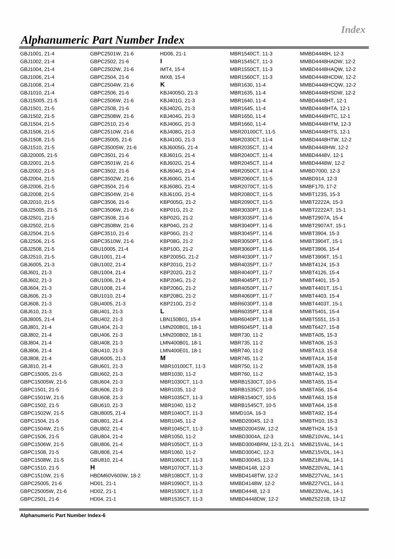
GBJ1001, 21-4 GBPC2501W, 21-6 HD06, 21-1 MBR1540CT, 11-3 MMBD4448H, 12-3GBJ1002, 21-4 GBPC2502, 21-6 I MBR1545CT, 11-3 MMBD4448HADW, 12-2GBJ1004, 21-4 GBPC2502W, 21-6 IMT4, 15-4 MBR1550CT, 11-3 MMBD4448HAQW, 12-2GBJ1006, 21-4 GBPC2504, 21-6 IMX8, 15-4 MBR1560CT, 11-3 MMBD4448HCDW, 12-2GBJ1008, 21-4 GBPC2504W, 21-6 K MBR1630, 11-4 MMBD4448HCQW, 12-2GBJ1010, 21-4 GBPC2506, 21-6 KBJ4005G, 21-3 MBR1635, 11-4 MMBD4448HSDW, 12-2GBJ15005, 21-5 GBPC2506W, 21-6 KBJ401G, 21-3 MBR1640, 11-4 MMBD4448HT, 12-1GBJ1501, 21-5 GBPC2508, 21-6 KBJ402G, 21-3 MBR1645, 11-4 MMBD4448HTA, 12-1GBJ1502, 21-5 GBPC2508W, 21-6 KBJ404G, 21-3 MBR1650, 11-4 MMBD4448HTC, 12-1GBJ1504, 21-5 GBPC2510, 21-6 KBJ406G, 21-3 MBR1660, 11-4 MMBD4448HTM, 12-3GBJ1506, 21-5 GBPC2510W, 21-6 KBJ408G, 21-3 MBR20100CT, 11-5 MMBD4448HTS, 12-1GBJ1508, 21-5 GBPC35005, 21-6 KBJ410G, 21-3 MBR2030CT, 11-4 MMBD4448HTW, 12-2GBJ1510, 21-5 GBPC35005W, 21-6 KBJ6005G, 21-4 MBR2035CT, 11-4 MMBD4448HW, 12-2GBJ20005, 21-5 GBPC3501, 21-6 KBJ601G, 21-4 MBR2040CT, 11-4 MMBD4448V, 12-1GBJ2001, 21-5 GBPC3501W, 21-6 KBJ602G, 21-4 MBR2045CT, 11-4 MMBD4448W, 12-2GBJ2002, 21-5 GBPC3502, 21-6 KBJ604G, 21-4 MBR2050CT, 11-4 MMBD7000, 12-3GBJ2004, 21-5 GBPC3502W, 21-6 KBJ606G, 21-4 MBR2060CT, 11-5 MMBD914, 12-3GBJ2006, 21-5 GBPC3504, 21-6 KBJ608G, 21-4 MBR2070CT, 11-5 MMBF170, 17-2GBJ2008, 21-5 GBPC3504W, 21-6 KBJ610G, 21-4 MBR2080CT, 11-5 MMBT123S, 15-3GBJ2010, 21-5 GBPC3506, 21-6 KBP005G, 21-2 MBR2090CT, 11-5 MMBT2222A, 15-3GBJ25005, 21-5 GBPC3506W, 21-6 KBP01G, 21-2 MBR3030PT, 11-6 MMBT2222AT, 15-1GBJ2501, 21-5 GBPC3508, 21-6 KBP02G, 21-2 MBR3035PT, 11-6 MMBT2907A, 15-4GBJ2502, 21-5 GBPC3508W, 21-6 KBP04G, 21-2 MBR3040PT, 11-6 MMBT2907AT, 15-1GBJ2504, 21-5 GBPC3510, 21-6 KBP06G, 21-2 MBR3045PT, 11-6 MMBT3904, 15-3GBJ2506, 21-5 GBPC3510W, 21-6 KBP08G, 21-2 MBR3050PT, 11-6 MMBT3904T, 15-1GBJ2508, 21-5 GBU10005, 21-4 KBP10G, 21-2 MBR3060PT, 11-6 MMBT3906, 15-4GBJ2510, 21-5 GBU1001, 21-4 KBP2005G, 21-2 MBR4030PT, 11-7 MMBT3906T, 15-1GBJ6005, 21-3 GBU1002, 21-4 KBP201G, 21-2 MBR4035PT, 11-7 MMBT4124, 15-3GBJ601, 21-3 GBU1004, 21-4 KBP202G, 21-2 MBR4040PT, 11-7 MMBT4126, 15-4GBJ602, 21-3 GBU1006, 21-4 KBP204G, 21-2 MBR4045PT, 11-7 MMBT4401, 15-3GBJ604, 21-3 GBU1008, 21-4 KBP206G, 21-2 MBR4050PT, 11-7 MMBT4401T, 15-1GBJ606, 21-3 GBU1010, 21-4 KBP208G, 21-2 MBR4060PT, 11-7 MMBT4403, 15-4GBJ608, 21-3 GBU4005, 21-3 KBP210G, 21-2 MBR6030PT, 11-8 MMBT4403T, 15-1GBJ610, 21-3 GBU401, 21-3 L MBR6035PT, 11-8 MMBT5401, 15-4GBJ8005, 21-4 GBU402, 21-3 LBN150B01, 15-4 MBR6040PT, 11-8 MMBT5551, 15-3GBJ801, 21-4 GBU404, 21-3 LMN200B01, 18-1 MBR6045PT, 11-8 MMBT6427, 15-8GBJ802, 21-4 GBU406, 21-3 LMN200B02, 18-1 MBR730, 11-2 MMBTA05, 15-3GBJ804, 21-4 GBU408, 21-3 LMN400B01, 18-1 MBR735, 11-2 MMBTA06, 15-3GBJ806, 21-4 GBU410, 21-3 LMN400E01, 18-1 MBR740, 11-2 MMBTA13, 15-8GBJ808, 21-4 GBU6005, 21-3 M MBR745, 11-2 MMBTA14, 15-8GBJ810, 21-4 GBU601, 21-3 MBR10100CT, 11-3 MBR750, 11-2 MMBTA28, 15-8GBPC15005, 21-5 GBU602, 21-3 MBR1030, 11-2 MBR760, 11-2 MMBTA42, 15-3GBPC15005W, 21-5 GBU604, 21-3 MBR1030CT, 11-3 MBRB1530CT, 10-5 MMBTA55, 15-4GBPC1501, 21-5 GBU606, 21-3 MBR1035, 11-2 MBRB1535CT, 10-5 MMBTA56, 15-4GBPC1501W, 21-5 GBU608, 21-3 MBR1035CT, 11-3 MBRB1540CT, 10-5 MMBTA63, 15-8GBPC1502, 21-5 GBU610, 21-3 MBR1040, 11-2 MBRB1545CT, 10-5 MMBTA64, 15-8GBPC1502W, 21-5 GBU8005, 21-4 MBR1040CT, 11-3 MIMD10A, 16-3 MMBTA92, 15-4GBPC1504, 21-5 GBU801, 21-4 MBR1045, 11-2 MMBD2004S, 12-3 MMBTH10, 15-3GBPC1504W, 21-5 GBU802, 21-4 MBR1045CT, 11-3 MMBD2004SW, 12-2 MMBTH24, 15-3GBPC1506, 21-5 GBU804, 21-4 MBR1050, 11-2 MMBD3004A, 12-3 MMBZ10VAL, 14-1GBPC1506W, 21-5 GBU806, 21-4 MBR1050CT, 11-3 MMBD3004BRM, 12-3, 21-1 MMBZ15VAL, 14-1GBPC1508, 21-5 GBU808, 21-4 MBR1060, 11-2 MMBD3004C, 12-3 MMBZ15VDL, 14-1GBPC1508W, 21-5 GBU810, 21-4 MBR1060CT, 11-3 MMBD3004S, 12-3 MMBZ18VAL, 14-1GBPC1510, 21-5 H MBR1070CT, 11-3 MMBD4148, 12-3 MMBZ20VAL, 14-1GBPC1510W, 21-5 HBDM60V600W, 18-2 MBR1080CT, 11-3 MMBD4148TW, 12-2 MMBZ27VAL, 14-1GBPC25005, 21-6 HD01, 21-1 MBR1090CT, 11-3 MMBD4148W, 12-2 MMBZ27VCL, 14-1GBPC25005W, 21-6 HD02, 21-1 MBR1530CT, 11-3 MMBD4448, 12-3 MMBZ33VAL, 14-1GBPC2501, 21-6 HD04, 21-1 MBR1535CT, 11-3 MMBD4448DW, 12-2 MMBZ5221B, 13-12
Alphanumeric Part Number Index-6
IndexAlphanumeric Part Number Index

MMBZ5221BS, 13-8 MMBZ5235B, 13-13 MMBZ5248BW, 13-8 MMDT3906, 15-3 MMSZ5234BS, 13-4MMBZ5221BT, 13-2 MMBZ5235BS, 13-9 MMBZ5250B, 13-13 MMDT3906VC, 15-1 MMSZ5235B, 13-16MMBZ5221BTS, 13-10 MMBZ5235BT, 13-3 MMBZ5250BS, 13-9 MMDT3946, 15-3 MMSZ5235BS, 13-4MMBZ5221BW, 13-7 MMBZ5235BTS, 13-10 MMBZ5250BT, 13-3 MMDT3946LP4, 15-1 MMSZ5236B, 13-16MMBZ5222B, 13-12 MMBZ5235BW, 13-7 MMBZ5250BTS, 13-10 MMDT4124, 15-2 MMSZ5236BS, 13-4MMBZ5223B, 13-12 MMBZ5236B, 13-13 MMBZ5250BW, 13-8 MMDT4126, 15-3 MMSZ5237B, 13-16MMBZ5223BS, 13-8 MMBZ5236BS, 13-9 MMBZ5251B, 13-13 MMDT4146, 15-3 MMSZ5237BS, 13-4MMBZ5223BT, 13-2 MMBZ5236BT, 13-3 MMBZ5251BS, 13-9 MMDT4401, 15-2 MMSZ5238B, 13-16MMBZ5223BTS, 13-10 MMBZ5236BTS, 13-10 MMBZ5251BT, 13-3 MMDT4403, 15-3 MMSZ5238BS, 13-4MMBZ5223BW, 13-7 MMBZ5236BW, 13-7 MMBZ5251BTS, 13-10 MMDT4413, 15-3 MMSZ5239B, 13-16MMBZ5225B, 13-12 MMBZ5237B, 13-13 MMBZ5251BW, 13-8 MMDT5401, 15-3 MMSZ5239BS, 13-4MMBZ5225BS, 13-8 MMBZ5237BS, 13-9 MMBZ5252B, 13-13 MMDT5451, 15-3 MMSZ5240B, 13-16MMBZ5225BT, 13-2 MMBZ5237BT, 13-3 MMBZ5252BS, 13-9 MMDT5551, 15-2 MMSZ5240BS, 13-4MMBZ5225BTS, 13-10 MMBZ5237BTS, 13-10 MMBZ5252BT, 13-3 MMDTA42, 15-4 MMSZ5241B, 13-16MMBZ5225BW, 13-7 MMBZ5237BW, 13-7 MMBZ5252BTS, 13-11 MMST2222A, 15-2 MMSZ5241BS, 13-4MMBZ5226B, 13-12 MMBZ5238B, 13-13 MMBZ5252BW, 13-8 MMST2907A, 15-2 MMSZ5242B, 13-16MMBZ5226BS, 13-8 MMBZ5238BS, 13-9 MMBZ5254B, 13-13 MMST3904, 15-2 MMSZ5242BS, 13-4MMBZ5226BT, 13-2 MMBZ5238BTS, 13-10 MMBZ5254BS, 13-9 MMST3906, 15-2 MMSZ5243B, 13-16MMBZ5226BTS, 13-10 MMBZ5239B, 13-13 MMBZ5254BT, 13-3 MMST4124, 15-2 MMSZ5243BS, 13-5MMBZ5226BW, 13-7 MMBZ5239BS, 13-9 MMBZ5254BTS, 13-11 MMST4126, 15-2 MMSZ5245B, 13-16MMBZ5227B, 13-12 MMBZ5239BT, 13-3 MMBZ5254BW, 13-8 MMST4401, 15-2 MMSZ5245BS, 13-5MMBZ5227BS, 13-8 MMBZ5239BTS, 13-10 MMBZ5255B, 13-13 MMST4403, 15-2 MMSZ5246B, 13-16MMBZ5227BT, 13-2 MMBZ5239BW, 13-7 MMBZ5255BS, 13-9 MMST5401, 15-2 MMSZ5246BS, 13-5MMBZ5227BTS, 13-10 MMBZ5240B, 13-13 MMBZ5255BT, 13-3 MMST5551, 15-2 MMSZ5248B, 13-16MMBZ5227BW, 13-7 MMBZ5240BS, 13-9 MMBZ5255BTS, 13-11 MMST6427, 15-8 MMSZ5248BS, 13-5MMBZ5228B, 13-13 MMBZ5240BT, 13-3 MMBZ5255BW, 13-8 MMSTA05, 15-2 MMSZ5250B, 13-16MMBZ5228BS, 13-8 MMBZ5240BTS, 13-10 MMBZ5256B, 13-13 MMSTA06, 15-2 MMSZ5250BS, 13-5MMBZ5228BT, 13-2 MMBZ5240BW, 13-7 MMBZ5256BS, 13-9 MMSTA13, 15-8 MMSZ5251B, 13-16MMBZ5228BTS, 13-10 MMBZ5241B, 13-13 MMBZ5256BT, 13-3 MMSTA14, 15-8 MMSZ5251BS, 13-5MMBZ5228BW, 13-7 MMBZ5241BS, 13-9 MMBZ5256BTS, 13-11 MMSTA42, 15-2 MMSZ5252B, 13-16MMBZ5229B, 13-13 MMBZ5241BT, 13-3 MMBZ5256BW, 13-8 MMSTA55, 15-2 MMSZ5252BS, 13-5MMBZ5229BS, 13-8 MMBZ5241BTS, 13-10 MMBZ5257B, 13-14 MMSTA56, 15-2 MMSZ5254B, 13-17MMBZ5229BT, 13-3 MMBZ5241BW, 13-7 MMBZ5257BS, 13-9 MMSTA63, 15-8 MMSZ5254BS, 13-5MMBZ5229BTS, 13-10 MMBZ5242B, 13-13 MMBZ5257BT, 13-3 MMSTA64, 15-8 MMSZ5255B, 13-17MMBZ5229BW, 13-7 MMBZ5242BS, 13-9 MMBZ5257BTS, 13-11 MMSTA92, 15-2 MMSZ5255BS, 13-5MMBZ5230B, 13-13 MMBZ5242BT, 13-3 MMBZ5257BW, 13-8 MMSZ5221B, 13-16 MMSZ5256B, 13-17MMBZ5230BS, 13-8 MMBZ5242BTS, 13-10 MMBZ5258B, 13-14 MMSZ5221BS, 13-4 MMSZ5256BS, 13-5MMBZ5230BT, 13-3 MMBZ5242BW, 13-7 MMBZ5258BS, 13-9 MMSZ5223B, 13-16 MMSZ5257B, 13-17MMBZ5230BTS, 13-10 MMBZ5243B, 13-13 MMBZ5258BT, 13-3 MMSZ5223BS, 13-4 MMSZ5257BS, 13-5MMBZ5230BW, 13-7 MMBZ5243BS, 13-9 MMBZ5258BTS, 13-11 MMSZ5225B, 13-16 MMSZ5258B, 13-17MMBZ5231B, 13-13 MMBZ5243BT, 13-3 MMBZ5258BW, 13-8 MMSZ5225BS, 13-4 MMSZ5258BS, 13-5MMBZ5231BS, 13-8 MMBZ5243BTS, 13-10 MMBZ5259B, 13-14 MMSZ5226B, 13-16 MMSZ5259B, 13-17MMBZ5231BT, 13-3 MMBZ5243BW, 13-8 MMBZ5259BS, 13-9 MMSZ5226BS, 13-4 MMSZ5259BS, 13-5MMBZ5231BTS, 13-10 MMBZ5244B, 13-13 MMBZ5259BT, 13-3 MMSZ5227B, 13-16 MUR120, 19-1MMBZ5231BW, 13-7 MMBZ5245B, 13-13 MMBZ5259BTS, 13-11 MMSZ5227BS, 13-4 MUR140, 19-1MMBZ5232B, 13-13 MMBZ5245BS, 13-9 MMBZ5259BW, 13-8 MMSZ5228B, 13-16 MUR160, 19-1MMBZ5232BS, 13-9 MMBZ5245BT, 13-3 MMBZ5V6AL, 14-1 MMSZ5228BS, 13-4 MURB1610CT, 19-8MMBZ5232BT, 13-3 MMBZ5245BTS, 13-10 MMBZ6V2AL, 14-1 MMSZ5229B, 13-16 MURB1620CT, 19-8MMBZ5232BTS, 13-10 MMBZ5245BW, 13-8 MMBZ6V8AL, 14-1 MMSZ5229BS, 13-4 MURS120, 19-1MMBZ5232BW, 13-7 MMBZ5246B, 13-13 MMBZ9V1AL, 14-1 MMSZ5230B, 13-16 MURS140, 19-1MMBZ5233B, 13-13 MMBZ5246BS, 13-9 MMDT2222A, 15-2 MMSZ5230BS, 13-4 MURS160, 19-1MMBZ5233BS, 13-9 MMBZ5246BT, 13-3 MMDT2222V, 15-1 MMSZ5231B, 13-16 MURS320, 19-6MMBZ5233BTS, 13-10 MMBZ5246BTS, 13-10 MMDT2227, 15-3 MMSZ5231BS, 13-4 NMMBZ5234B, 13-13 MMBZ5246BW, 13-8 MMDT2227M, 15-4 MMSZ5232B, 13-16 NMSD200B01, 18-2MMBZ5234BS, 13-9 MMBZ5248B, 13-13 MMDT2907A, 15-3 MMSZ5232BS, 13-4 PMMBZ5234BT, 13-3 MMBZ5248BS, 13-9 MMDT2907V, 15-1 MMSZ5233B, 13-16 P6KE10(C)A, 14-5MMBZ5234BTS, 13-10 MMBZ5248BT, 13-3 MMDT3904, 15-2 MMSZ5233BS, 13-4 P6KE100(C)A, 14-5MMBZ5234BW, 13-7 MMBZ5248BTS, 13-10 MMDT3904VC, 15-1 MMSZ5234B, 13-16 P6KE11(C)A, 14-5
Alphanumeric Part Number Index-7
IndexAlphanumeric Part Number Index

P6KE110(C)A, 14-5 PD3Z284C2V7, 13-6 PR1005GL, 19-3 PR6005, 19-8 S1B, 20-1P6KE12(C)A, 14-5 PD3Z284C30, 13-7 PR1005L, 19-2 Q S1BB, 20-1P6KE120(C)A, 14-5 PD3Z284C33, 13-7 PR1006G, 19-3 QSBT40, 9-2, 14-12 S1D, 20-1P6KE13(C)A, 14-5 PD3Z284C36, 13-7 PR1006GL, 19-3 QZX363C12, 13-12 S1DB, 20-1P6KE130(C)A, 14-5 PD3Z284C39, 13-7 PR1007G, 19-3 QZX363C15, 13-12 S1G, 20-1P6KE15(C)A, 14-5 PD3Z284C3V0, 13-6 PR1007GL, 19-3 QZX363C20, 13-12 S1GB, 20-1P6KE150(C)A, 14-5 PD3Z284C3V3, 13-6 PR1501, 19-4 QZX363C5V6, 13-12 S1J, 20-1P6KE16(C)A, 14-5 PD3Z284C3V6, 13-6 PR1501G, 19-5 QZX363C6V8, 13-12 S1JB, 20-1P6KE160(C)A, 14-5 PD3Z284C3V9, 13-6 PR1501GS, 19-4 QZX563C6V8C, 13-4 S1K, 20-1P6KE170(C)A, 14-5 PD3Z284C4V3, 13-6 PR1501S, 19-4 R S1KB, 20-1P6KE18(C)A, 14-5 PD3Z284C4V7, 13-6 PR1502, 19-4 RH02, 21-1 S1M, 20-1P6KE180(C)A, 14-5 PD3Z284C5V1, 13-6 PR1502G, 19-5 RH04, 21-1 S1MB, 20-1P6KE20(C)A, 14-5 PD3Z284C5V6, 13-6 PR1502GS, 19-4 RH06, 21-1 S2A, 20-2P6KE200(C)A, 14-5 PD3Z284C6V2, 13-6 PR1502S, 19-4 RS1A, 19-2 S2AA, 20-2P6KE22(C)A, 14-5 PD3Z284C6V8, 13-6 PR1503, 19-4 RS1AB, 19-2 S2B, 20-2P6KE220(C)A, 14-5 PD3Z284C7V5, 13-6 PR1503G, 19-5 RS1B, 19-2 S2BA, 20-2P6KE24(C)A, 14-5 PD3Z284C8V2, 13-6 PR1503GS, 19-4 RS1BB, 19-2 S2D, 20-2P6KE250(C)A, 14-5 PD3Z284C9V1, 13-6 PR1503S, 19-4 RS1D, 19-2 S2DA, 20-2P6KE27(C)A, 14-5 PDR3G, 20-4 PR1504, 19-4 RS1DB, 19-2 S2G, 20-2P6KE30(C)A, 14-5 PDR5G, 20-4 PR1504G, 19-5 RS1G, 19-2 S2GA, 20-2P6KE300(C)A, 14-5 PDS1040, 10-4 PR1504GS, 19-4 RS1GB, 19-2 S2J, 20-2P6KE33(C)A, 14-5 PDS1040CTL, 10-4 PR1504S, 19-4 RS1J, 19-2 S2JA, 20-2P6KE350(C)A, 14-5 PDS1040L, 10-4 PR1505, 19-4 RS1JB, 19-2 S2K, 20-2P6KE36(C)A, 14-5 PDS1045, 10-4 PR1505G, 19-5 RS1K, 19-2 S2KA, 20-2P6KE39(C)A, 14-5 PDS3100, 10-3 PR1505GS, 19-4 RS1KB, 19-2 S2M, 20-2P6KE400(C)A, 14-5 PDS3200, 10-3 PR1505S, 19-4 RS1M, 19-2 S2MA, 20-2P6KE43(C)A, 14-5 PDS340, 10-3 PR1506G, 19-5 RS1MB, 19-2 S3A, 20-4P6KE47(C)A, 14-5 PDS360, 10-3 PR1506GS, 19-4 RS2A, 19-4 S3AB, 20-4P6KE51(C)A, 14-5 PDS4150, 10-4 PR1507G, 19-5 RS2AA, 19-4 S3B, 20-4P6KE56(C)A, 14-5 PDS5100, 10-4 PR1507GS, 19-4 RS2B, 19-4 S3BB, 20-4P6KE62(C)A, 14-5 PDS5100H, 10-4 PR2001, 19-6 RS2BA, 19-4 S3D, 20-4P6KE68(C)A, 14-5 PDS540, 10-4 PR2001G, 19-6 RS2D, 19-4 S3DB, 20-4P6KE6V8(C)A, 14-5 PDS560, 10-4 PR2002, 19-6 RS2DA, 19-4 S3G, 20-4P6KE75(C)A, 14-5 PDS760, 10-4 PR2002G, 19-6 RS2G, 19-4 S3GB, 20-4P6KE7V5(C)A, 14-5 PDS835L, 10-4 PR2003, 19-6 RS2GA, 19-4 S3J, 20-4P6KE82(C)A, 14-5 PDU340, 19-6 PR2003G, 19-6 RS2J, 19-4 S3JB, 20-4P6KE8V2(C)A, 14-5 PDU420, 19-8 PR2004, 19-6 RS2JA, 19-4 S3K, 20-4P6KE91(C)A, 14-5 PDU540, 19-8 PR2004G, 19-6 RS2K, 19-4 S3KB, 20-4P6KE9V1(C)A, 14-5 PDU620, 19-8 PR2005, 19-6 RS2KA, 19-4 S3M, 20-4PD3S0230, 9-2 PDU620CT, 19-8 PR2005G, 19-6 RS2M, 19-4 S3MB, 20-4PD3S120L, 10-1 PR1001, 19-3 PR2006G, 19-6 RS2MA, 19-4 S5AC, 20-5PD3S130H, 10-1 PR1001G, 19-3 PR2007G, 19-6 RS3A, 19-7 S5BC, 20-5PD3S130L, 10-1 PR1001GL, 19-3 PR3001, 19-7 RS3AB, 19-7 S5DC, 20-5PD3S140, 10-1 PR1001L, 19-2 PR3001G, 19-7 RS3B, 19-7 S5GC, 20-5PD3S160, 10-1 PR1002, 19-3 PR3002, 19-7 RS3BB, 19-7 S5JC, 20-5PD3SD2580, 12-1 PR1002G, 19-3 PR3002G, 19-7 RS3D, 19-7 S5KC, 20-5PD3Z284C10, 13-6 PR1002GL, 19-3 PR3003, 19-7 RS3DB, 19-7 S5MC, 20-5PD3Z284C11, 13-6 PR1002L, 19-2 PR3003G, 19-7 RS3G, 19-7 S8KC, 20-5PD3Z284C12, 13-6 PR1003, 19-3 PR3004, 19-7 RS3GB, 19-7 S8MC, 20-5PD3Z284C13, 13-7 PR1003G, 19-3 PR3004G, 19-7 RS3J, 19-7 SB1100, 11-1PD3Z284C15, 13-7 PR1003GL, 19-3 PR3005, 19-7 RS3JB, 19-7 SB120, 11-1PD3Z284C16, 13-7 PR1003L, 19-2 PR3005G, 19-7 RS3K, 19-7 SB130, 11-1PD3Z284C18, 13-7 PR1004, 19-3 PR3006G, 19-7 RS3KB, 19-7 SB140, 11-1PD3Z284C20, 13-7 PR1004G, 19-3 PR3007G, 19-7 RS3M, 19-7 SB150, 11-1PD3Z284C22, 13-7 PR1004GL, 19-3 PR6001, 19-8 RS3MB, 19-7 SB160, 11-1PD3Z284C24, 13-7 PR1004L, 19-2 PR6002, 19-8 S SB170, 11-1PD3Z284C27, 13-7 PR1005, 19-3 PR6003, 19-8 S1A, 20-1 SB180, 11-1PD3Z284C2V4, 13-6 PR1005G, 19-3 PR6004, 19-8 S1AB, 20-1 SB190, 11-1
Alphanumeric Part Number Index-8
Alphanumeric Part Number IndexIndex

SB3100, 11-1 SBL1645, 11-4 SBR10150CTFP, 11-3 SBR2U30P1, 10-2 SD103ATW, 9-3SB320, 11-1 SBL1645CT, 11-4 SBR1040CT, 11-3 SBR2U30SA, 10-3 SD103AW, 9-3SB330, 11-1 SBL1645PT, 11-4 SBR1040CTFP, 11-3 SBR30100CT, 11-6 SD103AWS, 9-2SB340, 11-1 SBL1650, 11-4 SBR1060CT, 11-3 SBR30100CTFP, 11-6 SD103BW, 9-3SB350, 11-1 SBL1650CT, 11-4 SBR1060CTFP, 11-3 SBR30150CT, 11-6 SD103BWS, 9-2SB360, 11-1 SBL1650PT, 11-4 SBR10U100CT, 11-3 SBR30150CTFP, 11-6 SD103CW, 9-3SB370, 11-1 SBL1660, 11-4 SBR10U100CTFP, 11-3 SBR30200CT, 11-6 SD103CWS, 9-2SB380, 11-1 SBL1660CT, 11-4 SBR10U150CT, 11-3 SBR30200CTFP, 11-6 SD107WS, 9-2SB390, 11-1 SBL1660PT, 11-4 SBR10U150CTFP, 11-3 SBR30300CT, 11-6 SD830, 11-2SB5100, 11-1 SBL2030CT, 11-4 SBR10U200CT, 11-3 SBR30300CTFP, 11-6 SD840, 11-2SB520, 11-1 SBL2030PT, 11-5 SBR10U200CTB, 10-5 SBR3040CT, 11-6 SD845, 11-2SB530, 11-1 SBL2035CT, 11-4 SBR10U200CTFP, 11-3 SBR3040CTFP, 11-6 SD860, 11-2SB540, 11-1 SBL2035PT, 11-5 SBR10U300CT, 11-3 SBR3045CT, 11-6 SD930, 11-2SB550, 11-1 SBL2040CT, 11-4 SBR10U300CTFP, 11-3 SBR3045CTFP, 11-6 SD940, 11-2SB560, 11-1 SBL2040PT, 11-5 SBR10U40CT, 11-3 SBR3060CT, 11-6 SD945, 11-2SB570, 11-1 SBL2045CT, 11-4 SBR10U40CTFP, 11-3 SBR3060CTFP, 11-6 SDA004, 12-2, 14-12SB580, 11-1 SBL2045PT, 11-5 SBR10U60CT, 11-3 SBR30A100CT, 11-6 SDA006, 12-2, 14-12SB590, 11-1 SBL2050CT, 11-4 SBR10U60CTFP, 11-3 SBR30A100CTFP, 11-6 SDM03MT40, 9-4SBG1025L, 10-5 SBL2050PT, 11-5 SBR130S3, 10-1 SBR30A120CT, 11-6 SDM03MT40A, 9-4SBG1030CT, 10-5 SBL2060CT, 11-5 SBR140S3, 10-1 SBR30A150CT, 11-6 SDM03U40, 9-1SBG1030L, 10-5 SBL2060PT, 11-5 SBR20100CT, 11-5 SBR30A150CTFP, 11-6 SDM100K30L, 10-1SBG1035CT, 10-5 SBL3030PT, 11-6 SBR20100CTFP, 11-5 SBR30A40CT, 11-6 SDM10K45, 9-2SBG1040CT, 10-5 SBL3035PT, 11-6 SBR20150CT, 11-5 SBR30A40CTFP, 11-6 SDM10M45SD, 9-4SBG1045CT, 10-5 SBL3040PT, 11-6 SBR20150CTFP, 11-5 SBR30A45CT, 11-6 SDM10P45, 9-1SBG1630CT, 10-5 SBL3045PT, 11-6 SBR2040CT, 11-4 SBR30A45CTFP, 11-6 SDM10U45, 9-1SBG1635CT, 10-5 SBL3050PT, 11-6 SBR2040CTFP, 11-5 SBR30A60CT, 11-6 SDM10U45LP, 9-1SBG1640CT, 10-5 SBL3060PT, 11-6 SBR2045CT, 11-4 SBR30A60CTFP, 11-6 SDM20E40C, 9-4SBG1645CT, 10-5 SBL4030PT, 11-7 SBR2045CTFP, 11-5 SBR30M100CT, 11-6 SDM20N40A, 9-3SBG2030CT, 10-5 SBL4035PT, 11-7 SBR2060CT, 11-5 SBR30M100CTFP, 11-6 SDM20U30, 9-1SBG2035CT, 10-5 SBL4040PT, 11-7 SBR2060CTFP, 11-5 SBR30U30CT, 11-6 SDM20U30LP, 9-1SBG2040CT, 10-5 SBL4045PT, 11-7 SBR20A100CT, 11-5 SBR3A40SA, 10-3 SDM20U40, 9-1SBG2045CT, 10-5 SBL4050PT, 11-7 SBR20A100CTFP, 11-5 SBR3M30P1, 10-3 SDM40E20LA, 9-3SBG3030CT, 10-5 SBL4060PT, 11-7 SBR20A120CT, 11-5 SBR3U100LP, 10-3 SDM40E20LC, 9-3SBG3040CT, 10-5 SBL530, 11-1 SBR20A150CT, 11-5 SBR3U150LP, 10-3 SDM40E20LS, 9-3SBG3045CT, 10-5 SBL535, 11-1 SBR20A150CTFP, 11-5 SBR3U30P1, 10-3 SDM6CC, 9-1SBG3050CT, 10-5 SBL540, 11-1 SBR20A200CT, 11-5 SBR3U40P1, 10-3 SDMG0340L, 9-2SBG3060CT, 10-5 SBL545, 11-1 SBR20A200CTB, 10-5 SBR40100CT, 11-7 SDMG0340LA, 9-2SBL1030, 11-2 SBL550, 11-1 SBR20A200CTFP, 11-5 SBR40100CTFP, 11-7 SDMG0340LC, 9-2SBL1030CT, 11-3 SBL560, 11-1 SBR20A300CT, 11-5 SBR40150CT, 11-7 SDMG0340LS, 9-2SBL1035, 11-2 SBL6030PT, 11-8 SBR20A300CTB, 10-5 SBR40150CTFP, 11-7 SDMK0340L, 9-2SBL1035CT, 11-3 SBL6040PT, 11-8 SBR20A300CTFP, 11-5 SBR4040CT, 11-7 SDMP0340LAT, 9-1SBL1040, 11-2 SBL6050PT, 11-8 SBR20A40CT, 11-4 SBR4040CTFP, 11-7 SDMP0340LCT, 9-1SBL1040CT, 11-3 SBL6060PT, 11-8 SBR20A40CTFP, 11-5 SBR4045CT, 11-7 SDMP0340LST, 9-1SBL1045, 11-2 SBL830, 11-2 SBR20A45CT, 11-4 SBR4045CTFP, 11-7 SDMP0340LT, 9-1SBL1045CT, 11-3 SBL835, 11-2 SBR20A45CTFP, 11-5 SBR4060CT, 11-7 SF10AG, 19-1SBL1050, 11-2 SBL840, 11-2 SBR20A60CT, 11-5 SBR4060CTFP, 11-7 SF10BG, 19-1SBL1050CT, 11-3 SBL845, 11-2 SBR20A60CTFP, 11-5 SBR40U100CT, 11-7 SF10CG, 19-1SBL1060, 11-2 SBL850, 11-2 SBR20U100CT, 11-5 SBR40U45CT, 11-7 SF10DG, 19-1SBL1060CT, 11-3 SBL860, 11-2 SBR20U100CTFP, 11-5 SBR40U60CT, 11-7 SF10FG, 19-1SBL1630, 11-4 SBR0220LP, 9-1 SBR20U150CT, 11-5 SBR60A300CT, 11-7 SF10GG, 19-1SBL1630CT, 11-4 SBR0220T5, 9-1 SBR20U150CTFP, 11-5 SBR60A60CT, 11-7 SF10HG, 19-1SBL1630PT, 11-4 SBR0230T5, 9-1 SBR20U40CT, 11-4 SD101AW, 9-3 SF10JG, 19-1SBL1635, 11-4 SBR02M30LP, 9-1 SBR20U40CTFP, 11-5 SD101AWS, 9-2 SF20AG, 19-5SBL1635CT, 11-4 SBR02U100LP, 9-1 SBR20U60CT, 11-5 SD101BW, 9-3 SF20BG, 19-5SBL1635PT, 11-4 SBR05U20LP, 10-1 SBR20U60CTFP, 11-5 SD101BWS, 9-2 SF20CG, 19-5SBL1640, 11-4 SBR10100CT, 11-3 SBR2A30P1, 10-2 SD101CW, 9-3 SF20DG, 19-5SBL1640CT, 11-4 SBR10100CTFP, 11-3 SBR2A40P1, 10-2 SD101CWS, 9-2 SF20FG, 19-5SBL1640PT, 11-4 SBR10150CT, 11-3 SBR2M30P1, 10-2 SD103ASDM, 9-4, 21-1 SF20GG, 19-5
Alphanumeric Part Number Index-9
IndexAlphanumeric Part Number Index

SF20HG, 19-5 SMAZ15, 13-19 SMBJ8.0(C)A, 14-3 TB0640M, 14-10 UF1502S, 19-3SF20JG, 19-5 SMAZ16, 13-19 SMBJ8.5(C)A, 14-3 TB0720H, 14-10 UF1503, 19-4SF30AG, 19-6 SMAZ18, 13-19 SMBJ85(C)A, 14-4 TB0720L, 14-9 UF1503S, 19-3SF30BG, 19-6 SMAZ20, 13-19 SMBJ9.0(C)A, 14-3 TB0720M, 14-10 UF1504, 19-4SF30CG, 19-6 SMAZ22, 13-19 SMBJ90(C)A, 14-4 TB0900H, 14-10 UF1504S, 19-3SF30DG, 19-6 SMAZ24, 13-19 SMBT70A, 14-4 TB0900L, 14-9 UF1505, 19-4SF30FG, 19-6 SMAZ27, 13-19 SMCJ10(C)A, 14-6 TB0900M, 14-10 UF1505S, 19-3SF30GG, 19-6 SMAZ30, 13-19 SMCJ100(C)A, 14-6 TB1100H, 14-10 UF1506, 19-4SF30HG, 19-6 SMAZ33, 13-19 SMCJ11(C)A, 14-6 TB1100L, 14-9 UF1506S, 19-3SF30JG, 19-6 SMAZ36, 13-19 SMCJ110(C)A, 14-6 TB1100M, 14-10 UF1507, 19-4SMAJ10(C)A, 14-2 SMAZ39, 13-19 SMCJ12(C)A, 14-6 TB1300H, 14-10 UF1507S, 19-3SMAJ100(C)A, 14-3 SMAZ5V1, 13-19 SMCJ120(C)A, 14-6 TB1300L, 14-9 UF2001, 19-5SMAJ11(C)A, 14-2 SMAZ5V6, 13-19 SMCJ13(C)A, 14-6 TB1300M, 14-10 UF2002, 19-5SMAJ110(C)A, 14-3 SMAZ6V2, 13-19 SMCJ130(C)A, 14-6 TB1500H, 14-10 UF2003, 19-5SMAJ12(C)A, 14-2 SMAZ6V8, 13-19 SMCJ14(C)A, 14-6 TB1500L, 14-9 UF2004, 19-5SMAJ120(C)A, 14-3 SMAZ7V5, 13-19 SMCJ15(C)A, 14-6 TB1500M, 14-10 UF2005, 19-5SMAJ13(C)A, 14-2 SMAZ8V2, 13-19 SMCJ150(C)A, 14-6 TB1800H, 14-10 UF2006, 19-5SMAJ130(C)A, 14-3 SMAZ9V1, 13-19 SMCJ16(C)A, 14-6 TB1800L, 14-9 UF2007, 19-5SMAJ14(C)A, 14-2 SMBJ10(C)A, 14-3 SMCJ160(C)A, 14-6 TB1800M, 14-10 UF3001, 19-7SMAJ15(C)A, 14-2 SMBJ100(C)A, 14-4 SMCJ17(C)A, 14-6 TB2300H, 14-10 UF3002, 19-7SMAJ150(C)A, 14-3 SMBJ11(C)A, 14-3 SMCJ170(C)A, 14-6 TB2300L, 14-9 UF3003, 19-7SMAJ16(C)A, 14-2 SMBJ110(C)A, 14-4 SMCJ18(C)A, 14-6 TB2300M, 14-10 UF3004, 19-7SMAJ160(C)A, 14-3 SMBJ12(C)A, 14-4 SMCJ20(C)A, 14-6 TB2600H, 14-10 UF3005, 19-7SMAJ17(C)A, 14-3 SMBJ120(C)A, 14-4 SMCJ22(C)A, 14-6 TB2600L, 14-9 UF3006, 19-7SMAJ170(C)A, 14-3 SMBJ13(C)A, 14-4 SMCJ24(C)A, 14-6 TB2600M, 14-10 UF3007, 19-7SMAJ18(C)A, 14-3 SMBJ130(C)A, 14-4 SMCJ26(C)A, 14-6 TB3100H, 14-10 UG1001, 19-2SMAJ20(C)A, 14-3 SMBJ14(C)A, 14-4 SMCJ28(C)A, 14-6 TB3100L, 14-9 UG1002, 19-2SMAJ22(C)A, 14-3 SMBJ15(C)A, 14-4 SMCJ30(C)A, 14-6 TB3100M, 14-10 UG1003, 19-2SMAJ24(C)A, 14-3 SMBJ150(C)A, 14-4 SMCJ33(C)A, 14-6 TB3500H, 14-10 UG1004, 19-2SMAJ26(C)A, 14-3 SMBJ16(C)A, 14-4 SMCJ36(C)A, 14-6 TB3500L, 14-9 UG1005, 19-2SMAJ28(C)A, 14-3 SMBJ160(C)A, 14-4 SMCJ40(C)A, 14-6 TB3500M, 14-10 UG2001, 19-5SMAJ30(C)A, 14-3 SMBJ17(C)A, 14-4 SMCJ43(C)A, 14-6 TBZ363C20V8, 13-12 UG2002, 19-5SMAJ33(C)A, 14-3 SMBJ170(C)A, 14-4 SMCJ45(C)A, 14-6 TBZ363C5V5, 13-12 UG2003, 19-5SMAJ36(C)A, 14-3 SMBJ18(C)A, 14-4 SMCJ48(C)A, 14-6 TBZ363C6V4, 13-12 UG2004, 19-5SMAJ40(C)A, 14-3 SMBJ20(C)A, 14-4 SMCJ5.0(C)A, 14-6 TBZ363C7V0, 13-12 UG2005, 19-5SMAJ43(C)A, 14-3 SMBJ22(C)A, 14-4 SMCJ51(C)A, 14-6 TPD6V8LP, 14-1 UG3001, 19-7SMAJ45(C)A, 14-3 SMBJ24(C)A, 14-4 SMCJ54(C)A, 14-6 U UG3002, 19-7SMAJ48(C)A, 14-3 SMBJ26(C)A, 14-4 SMCJ58(C)A, 14-6 UDZ10B, 13-4 UG3003, 19-7SMAJ5.0(C)A, 14-2 SMBJ28(C)A, 14-4 SMCJ6.0(C)A, 14-6 UDZ11B, 13-4 UG3004, 19-7SMAJ51(C)A, 14-3 SMBJ30(C)A, 14-4 SMCJ6.5(C)A, 14-6 UDZ12B, 13-5 UG3005, 19-7SMAJ54(C)A, 14-3 SMBJ33(C)A, 14-4 SMCJ60(C)A, 14-6 UDZ13B, 13-5 US1A, 19-1SMAJ58(C)A, 14-3 SMBJ36(C)A, 14-4 SMCJ64(C)A, 14-6 UDZ15B, 13-5 US1B, 19-1SMAJ6.0(C)A, 14-2 SMBJ40(C)A, 14-4 SMCJ7.0(C)A, 14-6 UDZ5V1B, 13-4 US1D, 19-1SMAJ6.5(C)A, 14-2 SMBJ43(C)A, 14-4 SMCJ7.5(C)A, 14-6 UDZ5V6B, 13-4 US1G, 19-1SMAJ60(C)A, 14-3 SMBJ45(C)A, 14-4 SMCJ70(C)A, 14-6 UDZ6V2B, 13-4 US1J, 19-1SMAJ64(C)A, 14-3 SMBJ48(C)A, 14-4 SMCJ75(C)A, 14-6 UDZ6V8B, 13-4 US1K, 19-1SMAJ7.0(C)A, 14-2 SMBJ5.0(C)A, 14-3 SMCJ78(C)A, 14-6 UDZ7V5B, 13-4 US1M, 19-1SMAJ7.5(C)A, 14-2 SMBJ51(C)A, 14-4 SMCJ8.0(C)A, 14-6 UDZ8V2B, 13-4 WSMAJ70(C)A, 14-3 SMBJ54(C)A, 14-4 SMCJ8.5(C)A, 14-6 UDZ9V1B, 13-4 W005G, 21-2SMAJ75(C)A, 14-3 SMBJ58(C)A, 14-4 SMCJ85(C)A, 14-6 UF1001, 19-1 W01G, 21-2SMAJ78(C)A, 14-3 SMBJ6.0(C)A, 14-3 SMCJ9.0(C)A, 14-6 UF1002, 19-1 W02G, 21-2SMAJ8.0(C)A, 14-2 SMBJ6.5(C)A, 14-3 SMCJ90(C)A, 14-6 UF1003, 19-1 W04G, 21-2SMAJ8.5(C)A, 14-2 SMBJ60(C)A, 14-4 T UF1004, 19-1 W06G, 21-2SMAJ85(C)A, 14-3 SMBJ64(C)A, 14-4 T12S5, 14-1 UF1005, 19-1 W08G, 21-2SMAJ9.0(C)A, 14-2 SMBJ7.0(C)A, 14-3 T3V3S5, 14-1 UF1006, 19-1 W10G, 21-2SMAJ90(C)A, 14-3 SMBJ7.5(C)A, 14-3 T5V0S5, 14-1 UF1007, 19-1SMAT70A, 14-3 SMBJ70(C)A, 14-4 T6V0S5, 14-1 UF1501, 19-4SMAZ10, 13-19 SMBJ75(C)A, 14-4 TB0640H, 14-10 UF1501S, 19-3SMAZ12, 13-19 SMBJ78(C)A, 14-4 TB0640L, 14-9 UF1502, 19-4
Alphanumeric Part Number Index-10
Alphanumeric Part Number IndexIndex