dimov stojče ilčev - durban university of technology · cns systems (pty) ltd cns systems...
TRANSCRIPT

Sources for Future African Multipurpose GEO Satellites
(FAMGS)Presentation by:
Dimov Stojče IlčevDurban University of Technology (DUT)
Space Science Centre (SSC)CNS Systems
August 2012

CNS Systems (Pty) Ltd
CNS Systems (Former-
IS Marine Radio Ltd) is South African private company for design, Research and projects of Radio and SatelliteSystems for Communication, Navigation andSurveillance (CNS) and other aspects in the Space Program -
[www.cnssystems.co.za]

Space Science Centre

Aeronautical Communication, Navigation and Surveillance (CNS)
via Spacecraft

Soviet First Artificial Satellite Sputnik 1

First Russian Cosmonaut Yuri Gagarin Lifted in Orbit by Vostok 1
on 12 April 1961

First Commercail Communication Satellites Telstar 1 (Left) Launched by
US in 1962 and Intelsat 1 (Right) in 1964

Introduction of Multipurpose GEO Satellite
The South African company CNS Systems (Pty) Ltd and Space Science Centre (SSC) are potential andmain designers of novel Multipurpose GEO Satellite constellation for full coverage of the entire AfricanContinent and Middle East. The SSC Group at Durban University of Technology (DUT) may collaborate with similar institutes in the Country or Continent and provide essential projectof first Multipurpose GEO Satellite by Africans for Africa. What is Multipurpose GEO Satellite?This is an integration of GEO Communication with GNSS (Navigation) Payloads in a modern satellite configuration for CNS Solutions.

Advantages of Satellite Communications•
Wide Coverage Areas
•
Broadcast DVB-RCS Capability•
Broadcast CNS Solutions
•
Broadband, Multimedia and Internet Capability•
High Bandwidth
•
Flexibility in Network Set-up•
Mobility and Availability
•
Rapid Deployment•
Reliability and Safety
•
Economic Solutions Available•
Backbone in Areas without Adequate
Terrestrial Telecommunication and Cellular Infrastructures
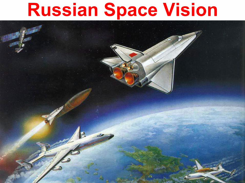
Russian Space Vision

US Space Vision

Negative Effects of Van Allen Radiation Belts [Inner Belt is from 1000 to 5000 km and Outer Belt is from
16000 to 24000 km above the Earth Surface. In 2012, observations from the Van Allen Probes showed that a Third Belt may appear after each Sun eruption. Passing through these belts is very dangerous for the life of cosmonauts]

Platforms and Orbital MechanicsThe platform is an artificial object located in orbitaround the Earth at a minimum altitude of about20 to 25 km in the stratosphere and a maximumdistance of about 36,000 km in the Space. In fact,a space platform is defined as an unattendedobject revolving about a larger one.Orbital mechanics is a specific Space disciplinedescribing planetary and satellite motion in theSolar system, which can solve the problems ofcalculating and determining the position, speed,path, perturbation and other orbital parameters of planets and satellites.

Kepler’s Laws of Satellite MotionA satellite is an artificial object located by rocket in space orbit following the same laws in its motion as the planets rotating around the Sun. In this sense, three so important laws for planetary motion were derived by scientists Johannes Kepler, as follows:1. First Law –
The orbit of each planet follows an elliptical
path in space with the Sun in one focus. Motion lies in the plane around the Sun (1602).2. Second Law –
The line from the Sun to planet or radius
vector (r) sweeps out equal areas in equal intervals of time.This is the Law of Areas (1605).3. Third Law –
The square of the planet’s orbital period
around the Sun (T) is proportional to the cube of the semi- major axis (a = distance from the Sun) of the ellipse for all
planets in the Solar system (1618).

Principia Mathematica of NewtonKepler’s Laws and theory were based on observational records and only described the planetary motion without attempting an additional theoretical or mathematical explanation of why the motion takes place in that manner. In 1687, Sir Isaac Newton published his breakthrough work“Principia Mathematica”
with own syntheses, known as the Three Laws of Motion:1. Law I –
Every body continues in its state of rest or uniform motion in a straight line, unless it is compelled to change that state by forces impressed on it.2. Law II –
The change of momentum per unit time of a body isproportional to the force impressed on it and is in the same direction as that force.3. Law III –
To every action there is always an equal and oppositereaction. Therefore, on the basis of Law II, Newton also formulated the Law of Universal Gravitation, which states that any two bodies attract one another with a force proportional to the products of their masses and inversely proportional to the square of distance between them.

Satellite Installation in Circular and Synchronous Orbit
[Direct and Indirect Ascent Launching]
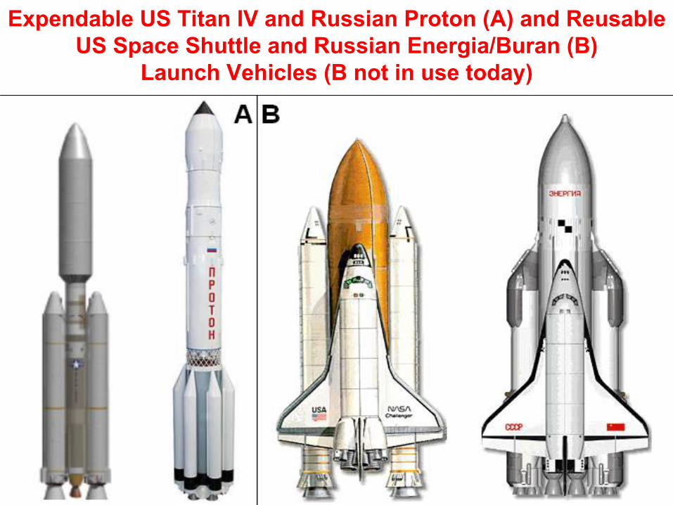
Expendable US Titan IV and Russian Proton (A) and Reusable US Space Shuttle and Russian Energia/Buran (B)
Launch Vehicles (B not in use today)

I. Evolution of Russian Launch Vehicles with Proton (4th from Right) as more
Reliable Rocket today

II. Evolution of Russian Launch Vehicles with Soyuz (3rd from Right) as a Present Successor

Evolution of US Rockets

Comparison of Different Launcher (Present *)

Ceased the US Space Shuttle and Russian Buran

Last Generation of Russian Launchers Angara 1.2; A3, A5 and A7

New Generation of Expendable and Reusable Spaceships

Russian New Heavy-lift Launcher Angara 100

Project of Russian Spaceplane Kliper

Spaceplane Kliper atop Launcher Soyuz

Comparison of Spaceships Soyuz and Kliper

Landing of the Kliper Reentry Vehicle or may be Grounded by means of a Parachute

Russian Nuclear Propulsion Systems to be Used on New Angara Boosters made
by Rosatom and Kurchatov Institute

Crew Exploration Vehicle (CEV) of the USA Company Lockheed-Martin

Crew Exploration Vehicle (CEV) of USA

CEV with Service Module both may be Connected atop Launcher

SeaLaunch System using Ukrainian (Ex-Soviet) Launcher Zenit

Global Coverage with 3 Inmarsat-4 Satellites similar to Sir Arthur Clarke

Global Coverage with 4 Inmarsat-3 Satellites
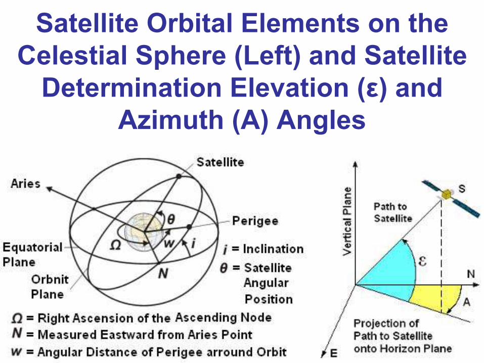
Satellite Orbital Elements on the Celestial Sphere (Left) and Satellite
Determination Elevation (ε) and Azimuth (A) Angles

Satellite Look Angles• Satellite azimuth is the angle measured eastward from the geographical North (N) line to the projection of the satellite path on the horizontal plane at the observer point.
• Satellite elevation is the angle composed upward from the horizon to the vertical satellite direction on the vertical plane at the observer point.

Calculation of Mobile Plotted Position (See next Slide)
•Elevation Angle Map (A) with Plotted Position 17º for Indian Ocean Region (IOR) and 25º for Atlantic Ocean Region (AOR)
•Azimuth Angle Map (B) with Plotted Position 57º for Indian Ocean Region (IOR) and 313º for Atlantic Ocean Region (AOR)

Elevation Angle Map and Plotted Position
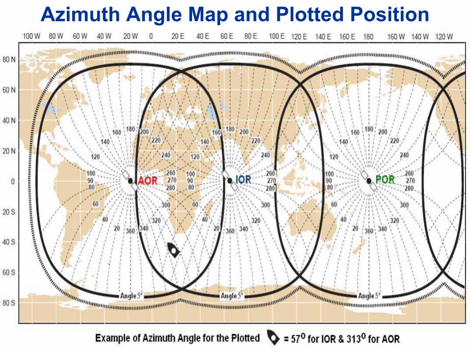
Azimuth Angle Map and Plotted Position

Type of Satellite Orbits1. Low Earth Orbits (LEO): Little and Big LEO2. Polar Earth Orbits (PEO)3. Medium Earth Orbits (MEO)4. Geosynchronous Inclined Orbits(GIO)5. Geostationary Earth Orbits (GEO)6. Highly Elliptical Orbits (HEO): Molnya, Tundra and Loopus.

Type of Satellite Orbits: HEO= High Elliptical Orbit;GEO = Geostationary Earth Orbit; MEO= Medium Earth Orbit; LEO= Low Earth Orbit & PEO = Polar
Earth Orbit

Properties of Four Major OrbitsOrbital Properties LEO MEO HEO GEO
Development PeriodLaunch & Satellite CostSatellite Life (Years)CongestionRadiation DamageOrbital PeriodInclinationCoverageAltitude Range (km-3)Satellite VisibilityHandoverElevation VariationsEccentricityHandheld TerminalNetwork ComplexityTx Power/Antenna GainPropagation DelayPropagation Loss
LongMaximum3–7LowZero<100 min90o
Global0.5–1.5ShortVery MuchRapid0 to HighPossibleComplexLowShortLowHigh
ShortMaximum10–15LowSmall8-12 hours45o
Global8–20MediumMediumSlowHighPossibleMediumLowMediumMediumMedium
MediumMedium2–4LowBig½
Sidereal Day63.4o
Near Global40/A –
1/PMediumNoZeroHighPossibleSimpleLow/HighLargeHighLow
LongMedium10–15HighSmall1 Sidereal DayZeroNear Global40 (i=0)ContinuousNoZeroZeroPossibleSimpleLow/HighLargeHighZero

Proposal: Hybrid Constellation of GEO and HEO Molnya with High Apogee to provide Real Global
Coverage

Proposal: Hybrid Constellation of GEO and PEO for Cospas-
Sarsat GEOSAR and LEOSAR Global Coverage
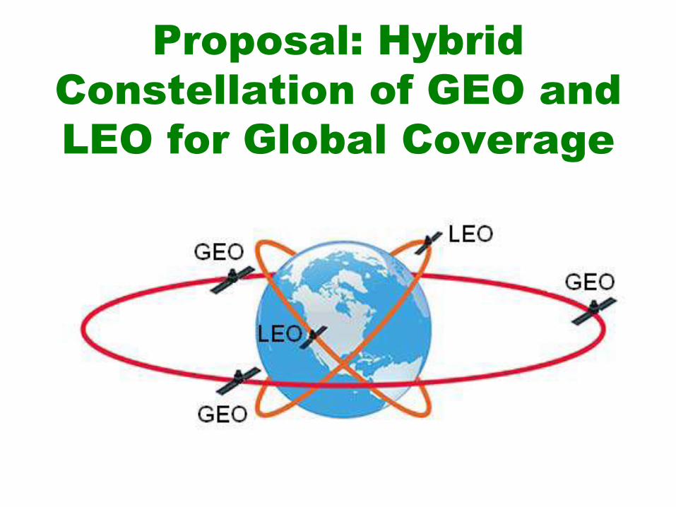
Proposal: Hybrid Constellation of GEO and LEO for Global Coverage

Proposal: Hybrid Constellations of HEO and MEO (Left) and MEO and LEO (Right) for Global Coverage

Spacecraft Sub-System

Three-axes Stabilized Spacecraft•
Momentum wheels in each axis: roll,pitch, yaw for stabilization
•
No despun platform needed forantennas
•
Large solar panels possible (powergeneration)
•
Optimum orientation towards the Sun•
High efficiency
•
More complex design•
More complicated thermal control

Spin-Stabilized Spacecraft•
Earliest version
•
Whole body is momentum wheel•
For stability the momentum arounddesired axis must be greater thanaround any other axis
•
Despun antenna platform for highergain antennas
•
Easy thermal balance•
Only ~ 1/3 of solar panel area useable

Components of GEO Spacecraft

Future Russian GEO Spacecraft Express-AM [which Bus can be model to build new Multifunctional Spacecraft]

Specifications of GEO Spacecraft Express-AM built by Russian Company ISS Reshetnev
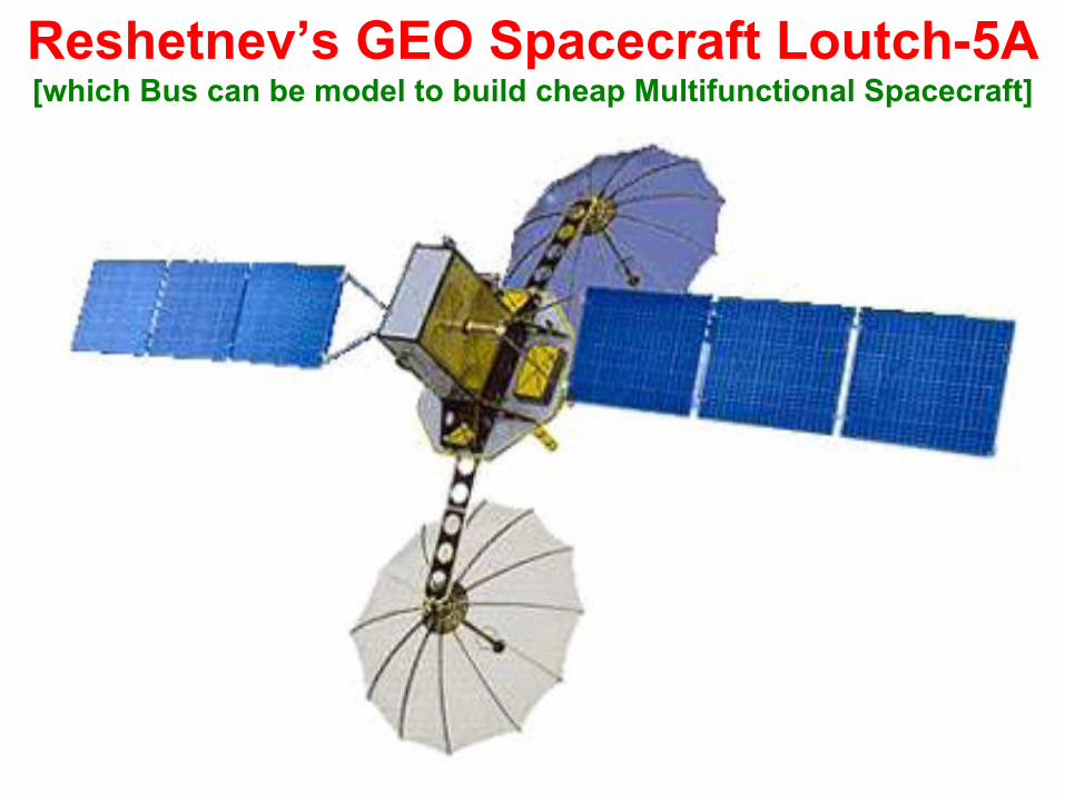
Reshetnev’s GEO Spacecraft Loutch-5A [which Bus can be model to build cheap Multifunctional Spacecraft]

The US GEO Spacecraft GOES

Multifunctional Japanese GEO Spacecraft MTSAT
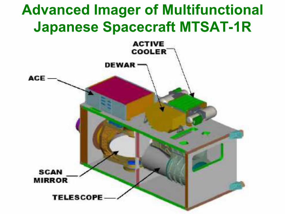
Advanced Imager of Multifunctional Japanese Spacecraft MTSAT-1R

Inter Satellite Link (ISL) Between GEO, LEO and High Altitude Platform (HAP)

Inter Platform and Satellite Links

Spacecraft Transparent or Bent-pipe (A) and Regenerative (B) or Onboard Processing
Transponder (Repeater)
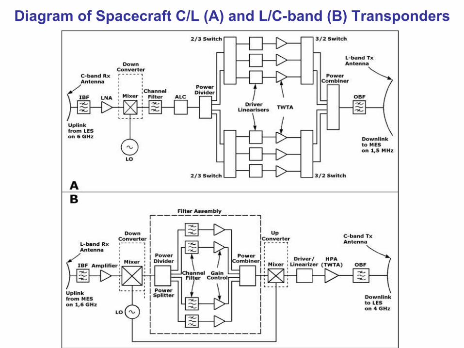
Diagram of Spacecraft C/L (A) and L/C-band (B) Transponders

Communication L/C-Band Transponder as a part of Multifunctional Payload

Block Diagram of Ka-band Communications Transponder

Diagram of VSAT Spacecraft Transponders

GNSS (Navigation) Transponder as a Part of Multifunctional Payload

GEO Satellite Mission Services– Mobile Satellite Communications:• Maritime Mobile Satellite Communications• Land (Road and Rail) Mobile Satellite Communications• Aeronautical Mobile Satellite Communications-
Fixed Satellite Communications:• DVB-RCS Communication via Star and Mesh Networks (Two-way VSAT)• DVB-RCS Voice, Data and Video over IP (VDVoIP) and IPTV Services• Communication links between Mobile and Ground Control Centers (GCC)• Mobile Services (Traffic Services and Operational Communication)• Passenger Services : VDVoIP, Telephony, Internet, SMS and so on– Satellite Navigation (GNSS) Augmentations:• Communication links between ground navigation system facilities (VSAT)• Broadcast of GNSS Augmentation signals to mobiles via Navigation Payload• Broadcast of GNSS signals from mobiles to GC– Service Coverage : Africa and Middle East

Satellite Networks via Transparent and Regenerative Transponders

DVB-RCS Concept of Global Broadcasting Satellite System (GBSS)

Our Proposal: Future South African GEO Constellation of CNS/DVB-RCS Networks for Mobile (MES) and Fixed Earth
Stations (FES)

Space Segment of Communication (GEO) and Global Navigation
Satellite System (GNSS) for CNS

1. Highlights of ASAS NetworkAs observed previous figure, all mobile users (3) receive navigation signals (1) from GNSS-1 of GPS or GLONASS satellites. In the near future can be used GNSS-2 signals of EU Galileo and Chinese Compass satellites (2). These GNSS signals are also received by all Reference Stations (RS) or Ground Monitoring Stations (GMS) of integrity monitoring networks (4) operated by governmental agencies within Africa and Middle East. The monitored data are sent to a regional Integrity and Processing Facility of Master Station or Ground Control Station (GCS) (5), where the data is processed to form the integrity and WADGNSS correction messages, which are then forwarded to the Primary GNSS GES (6).

2. Highlights
of ASAS NetworkAt the Ground Earth Station (GES), the navigation signals are precisely synchronized to a reference time and modulated with the GIC message data and WADGNSS corrections.
The signals are sent to a
satellite on the C-band uplink (7) via communication payload located in Inmarsat and Artemis satellite (8), the augmented signals are frequency-translated and after sent to the mobile user on GNSS L1 and new L5-band like GPS (9) and also to the C-band (10) used for maintaining the navigation signal timing loop. The timing of the signal is done in a very precise manner in order that the signal will appear as though it was generated on board the satellite as a GPS or GLONASS ranging signal.

3. Highlights
of ASAS NetworkThe Secondary GNSS GES can be separate or installed in Communication CNS GES (11), as a hot standby in the event of failure at the Primary GNSS GES. The Traffic Control Centres (TCC) terminals (12) could send request for CNS information by Voice, Data and Video (VDV) on C-band uplink (13) via Communication payload located in GEO spacecraft and on C-band downlink (14) to mobile users (3). The mobile users are able to send augmented CNS data on L-band uplink (15) via GEO communication payload and downlink (16). The TCC sites are processing CNS data received from mobile users and displaying on the like radar screen their current positions very accurate and in the real time for traffic control and management purpose.

4. Highlights
of ASAS NetworkThe most important and unique sequence in this stage is that traffic controller can use the position data for
managing certain traffic in more safe way
than surveillance radar for collision avoidance, during any weather or visibility conditions. In addition, on mobile request TCC operator maysend position data of each mobile in vicinity for enhanced collision
avoidance (13 and 14). Each
mobiles, such as ships and
aircraft will be also ableto provide polling of position data memorized in TCCfor any adjacent mobile (ship or aircraft) and
use it
for
enhanced collision avoidance.

Future African Multipurpose GEO Spacecraft Coverage

DVB-RCS Bands and Backhaul• Hub provides Voice, Data and Video over IP• (VDVoIP) & IPTV on C (4-8 GHz), Ku (12-18 GHz)• or Ka-band (27-
40 GHz) antenna interfaces and
• extends the Terrestrial Broadband, ISP, Video• Broadcasting, UMTS/GPRS (Universal Mobile• Telecommunications System/General Packet• Radio Service), Asynchronous Transfer Mode• (ATM), ISDN/ADSL, Fiber Optic Lines,
Terrestrial• Telecommunication Network (TTN), Cellular• Networks, Virtual Private Networks (VPN), etc.

Digital Video Broadcasting-Return Channel via Satellite (DVB-RCS) Solutions

Interactive Internet via DVB-RCS+M Backbone for Mobile Applications

DVB-RCS/S2 VSAT Network Configuration

Typical Fixed VSAT Satellite Network

DVB-RCS Backbone to Rural Areas

Fixed DVB-RCS Network Designed in 2000

E-education via DVB-RCS Network Designed in 2000

Mobile DVB-RCS Network Designed in 2000

Military DVB-RCS Network Designed in 2000

ESA Design of Mobile DVB-RCS Applications in 2006

DVB-RCS Architecture for Mobile Broadband

E-education via DVB-RCS
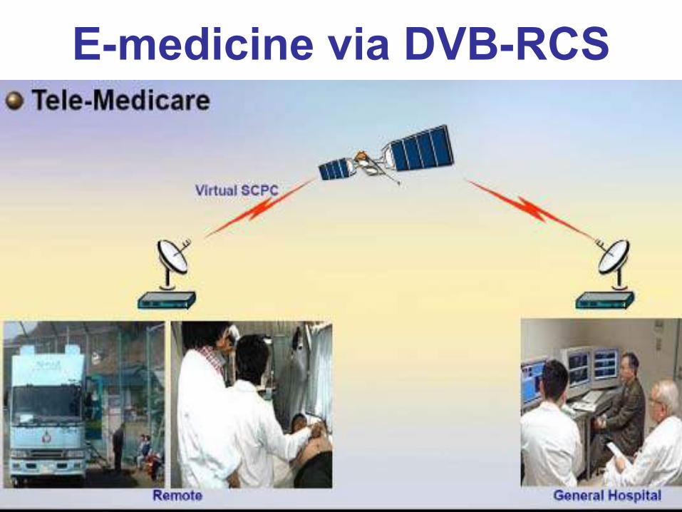
E-medicine via DVB-RCS

Wi-Fi Solutions via DVB-RCS
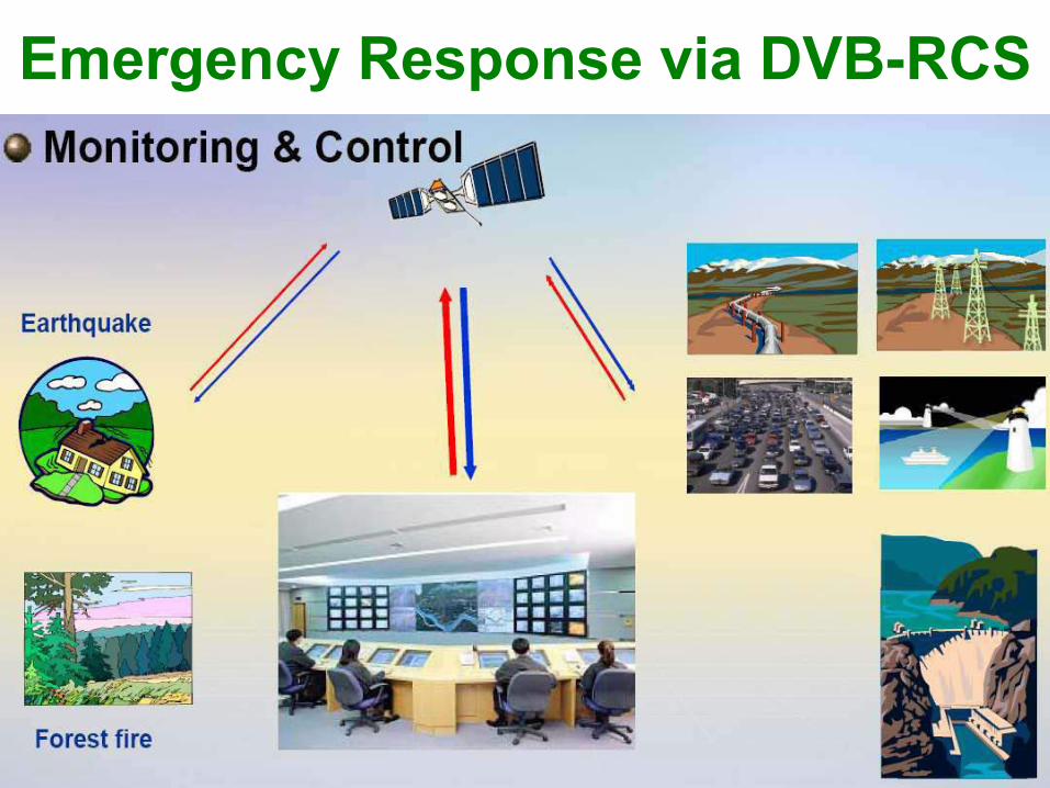
Emergency Response via DVB-RCS

DVB-RCS HUB Terminals of A) Advantech; B) ViaSat and C) Hughes

Advantech Family of DVB-RCS HUB Terminals
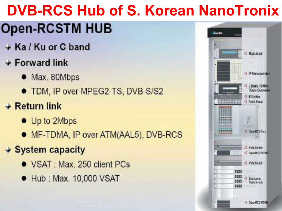
DVB-RCS Hub of S. Korean NanoTronix

DVB-RCS Terminals or VSAT

DVB-RCS VSAT Configuration

Remote In-Door Units (IDU) Terminals with Antenna or Out-Door Unit (ODU)

DVB-RCS Indoor and Outdoor Units

Satellite OperatorsThe current GEO Satellite Constellation Suitable for Satellite Communication, Navigation and Surveillance (CNS) Space Segment over Africa and Middle East is as follows:
1. Inmarsat Indian Ocean region (IOR)2. Inmarsat Atlantic Ocean Region East (AORE)3. Artemis
The Current GEO Satellites suitable for Space Digital Video Broadcasting-Return Channel via Satellite (DVB-RCS) system over Africa and Middle East are as follows:
1. Intelsat IS802 Spot Beam and PanAmSat PAS10 Ku band 3. SES –
NewSkies NSS71 Ku & C band
4. Eutelsat Ku & Ka band W3AResearch Group in Space Science at DUT already proposed a Multipurpose Space Segment of three GEO satellites for CNS over Africa and Middle East offering L/C, Ku and Ka-band with regional and spot coverages.

Global Intelsat DVB-RCS C-band Coverage for Maritime Applications

Global Intelsat DVB-RCS Ku-band Coverage for Maritime Applications

Global KVH DVB-RCS Ku-band VSAT Coverage for Maritime Applications

Yonder/ViaSat DVB-RCS Ku-band Coverage for Aeronautical Applications

Satellite Space and Ground Segment

DVB-RCS for Mobile Users

DVB-RCS VSAT (A) Star and (B) Mesh Connectivity with GEO
Spacecraft

DVB-RCS for Fixed and Portable Users

DVB-RCS for Fixed and Portable Users

Our Proposal: Shipborne DVB-RCS

NERA DVB-RCS Ku-band Unit for Maritime Applications

Our Proposal: CNS for Enhanced Ship Traffic Control (STC) and Seaports DVB-RCS

Coastal Movement Guidance and Control (CMGC)

ARINK DVB-RCS Ku-band Unit for Yonder Aeronautical Applications

Our Proposal: Airborne DVB-RCS

Our Proposal: CNS for Enhanced Air Traffic Control (ATC) and Airport DVB-RCS

Surface Movement Guidance and Control (SMGC)
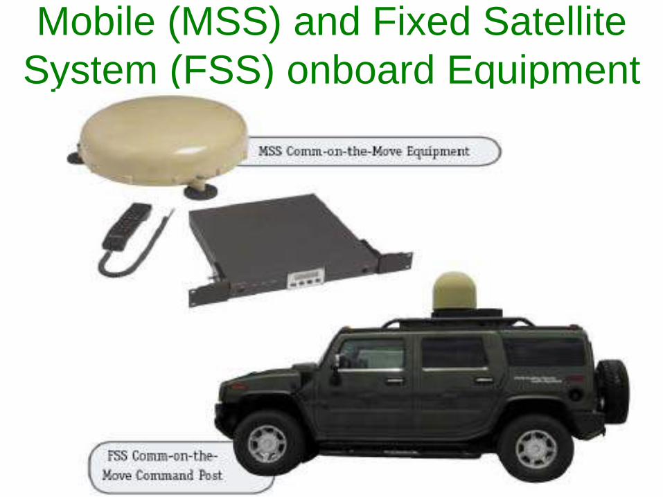
Mobile (MSS) and Fixed Satellite System (FSS) onboard Equipment

Land Movement Guidance and Control (LMGC)

Local Fixed or Mobile DVB-RCS Solutions

DVB-RCS C, Ku and Ka-band (A) ViaSat and (B) Hughes
Transceivers for Mobile Applications

Broadband Antenna Systems for Ships (A), Trains or Busses (B) &
Aircraft (C)
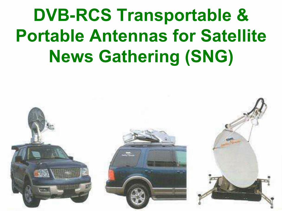
DVB-RCS Transportable & Portable Antennas for Satellite
News Gathering (SNG)

DVB-RCS Mobile and Portable Antennas for Military Applications

Functions of Satellite Payload/Bus
1. Spacecraft Solar Arrays2. Spacecraft Power Supply3. Thermal and Electrical Control4. Attitude and Orbital Control5. Spacecraft Telemetry, Trackingand Command (TT&C)6. Propulsion Engine7. Intersatellite Link System (ILS)

Modern Ka-band Payload Overview

Ku-band Solid State Transponder

Controls of the Antenna Pointing Mechanism (APM) and the Solar Array (SADE)
Applications- Telecommunications Satellites.- Scientific and Earth Observation missions.Main Features- Redundant Flight Units and Compact lightweight design.- Low Power CMOS technology.- Simultaneous control for two or more axis motors.- Step by step motors controlled by Micro-Stepping technique.- Angular acquisition by Optical or Magneto-resistive Encoders.Key Benefits- Flight heritage.- Multi-platform Compatibility

Inmarsat Spacecraft Antenna System (Left) and Principal Property
of a Parabolic Reflector (Right)

Mechanical Parts of APM and SADE

Spacecraft Solar Array

Electronic Parts of Satellite APM and SADE

Spacecraft Command Receivers (Specifications)

Spacecraft Command Receivers (Equipment)

Spacecraft C-Band Beacon Transmitter

Spacecraft Ku-band Beacon Transmitter

Spacecraft Telemetry Transmitter

Spacecraft Microwave Devices

Spacecraft Receiver of Regenerative Transponder
The components of Spacecraft Receivers (Rx)are as follows:1. Rx Antenna and Input Bandpass Filter (IBF)2. Low Noise Amplifier (LNA) and Downconverter3. Mixer/Local Oscillator (LO)4. Input Multiplexer (IMUX)5. Switch Assembly (SWA)6. Demodulator and Automatic Level Control (ALC)7. Power Divider and Onboard Processor (OBP)

Spacecraft Low Noise Amplifier (LNA)

Spacecraft L-band Low Noise Amplifier (LNA)
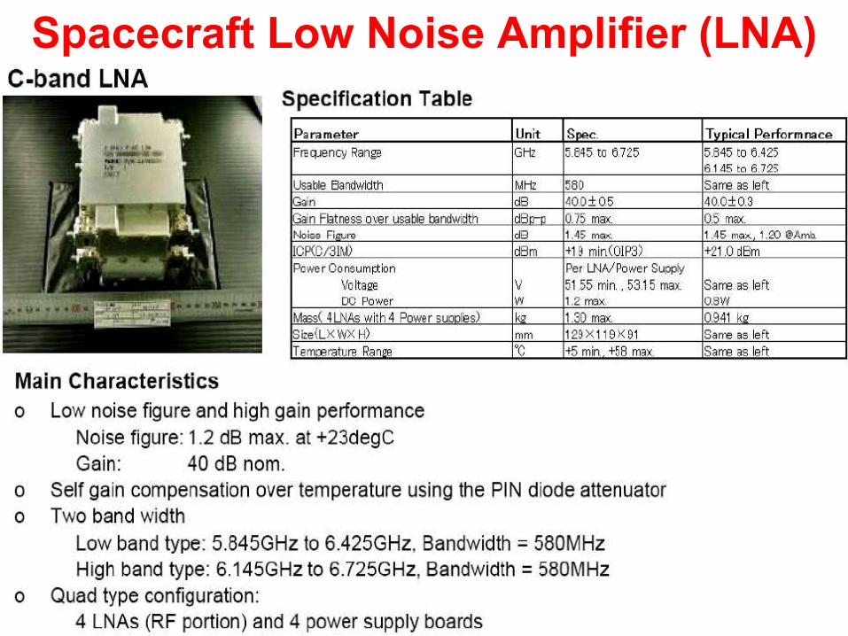
Spacecraft Low Noise Amplifier (LNA)

Spacecraft Ka-band Low Noise Amplifier (LNA)

Spacecraft C-Band Receiver/Downconverter

Spacecraft Ku-band Receiver/Downconverter for Broadband Satellite Service (BSS)

Spacecraft Ku-band Receiver/Downconverter for Fixed Satellite Service (FSS)

Spacecraft Ka/Ku-band Receiver/Downconverter

Spacecraft Ka-band Receiver/Downconverter

New Generation of Spacecraft Ka-band Downconverter

Spacecraft C/X/Ku/Ka-band Input Multiplexers (IMUX)

Spacecraft Transmitter of Regenerative Transponder
The components of Spacecraft Transmitter (Tx)are as follows:1. Onboard Processor (OBP)2. Modulator (MOD) and Channel Amplifier (CAMP)3. Linearizer (LIN)4. Upconverter/Mixer and Drivers5. Power Amplifier: Travelling Wave Tube Amplifier(TWTA) and Solid State Power Amplifier (SSPA)6. Switch Assembly (SWA)7. Tx Antenna
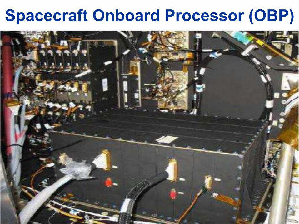
Spacecraft Onboard Processor (OBP)

Ka-band Modulator (A) and Dual TWTA (B)

Spacecraft High Linearity SSPA

Satellite C-band Solid State Power Amplifiers (SSPA)

Spacecraft C/Ka-band Upconverter

Spacecraft Ku/Ka-band Upconverter

Dual Microwave Power Module – MPM (A) and C-band OMUX (B)

Thanks for your attention!!!
Please, any questions?!
The EndThank you for your attention!
Space Science Centre (SSC)
DUTCNS Systems
Cell: +27 82 7650817; Tel: +27 31 3732692
E-mail: [email protected]