digsi 01 2007 englisch - siemens power...
TRANSCRIPT

DIGSI 4 May 2007
DIGSI 4 sNOTES
MM AA YY 22 00 00 77 EE DD II TT II OO NN EE NN GG LL II SS HH AA NN DD GG EE RR MM AA NN
ENGLISH
Many protection setting programs areequipped with an export interface,but often the import is just not sup-ported. But in fact this is especially in-teresting: Data from other applica-tions can be read into the protectionoperating software – after a conver-sion, if required. Often these data arethe result of complicated calculations,for example in MS EXCEL settingsheets or in network calculation soft-ware. A simple transfer saves enginee-ring costs, and of course it also pre-vents typing errors.
DIGSI 4.80 is equipped with an im-port/export interface which allows the
DIGSI now talks XML
INSIDE
TOPICS
DIGSI now talks XML PAGE 1
Insights into the DIGSI
XML format PAGE 2
DIGSI 4.80 has been approved
for three months PAGE 2
SIGRA 4 you PAGE 3
PRESENTED
It’s a pleasure to measure PAGE 3
HINTS & TRICKS
Take-over of settings from EXCEL PAGE 4
QUESTIONS AND ANSWERS PAGE 6
LATEST NEWS PAGE 6
COMING SOON PAGE 6
The DIGSI XML import and export interface for the exchange of data of SIPROTECprotection devices offers the user new and cost-reducing possibilities: The user canread data from other applications into DIGSI via the import interface and thus para-meterise devices from outside. On the other hand, the setting data can be transmit-ted to other applications and can be processed there.
exchange of protection settings andsignal connections in both directionsfor all the devices of the SIPROTEC 4family.
XML – universal, easily readable, struc-tured and platform-independent
While the data output of most of thesetting programs is restricted to asimple ASCII text or, in some cases,uses the database format CSV, a dif-ferent strategy has been pursued forDIGSI from the beginning: DIGSI of-fers a universal format that is inde-pendent from the platform, compre-hensible and durable, based on thestandardised data description lan-guage XML (Extensible Markup Lan-guage). In DIGSI XML, in accordancewith the pertinent standard, suitableXML tags are offered that representthe structure of the parameter set onthe one hand, and describe themeaning of the parameter on theother hand. Therefore the DIGSI XMLformat has a decisive advantage fromthe user's point of view: It is readable,well-structured with only a few levelsand can be learnt easily and quickly.Only what is visible at the DIGSI userinterface or what is included in theannex of every manual will be includ-ed in the exchange file: the text ele-ments in the parameterising dialog canbe found in the DIGSI XML code too.

2 May 2007 DIGSI 4
Insights into the DIGSI XML format
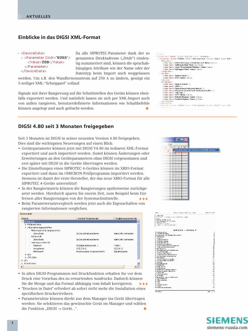
Since all the SIPROTEC parameters areclearly numbered by means of the so-calleddirect address (“DAdr”), the attributeswhich are language-independent, such asthe name or the data type, can be omitted
during import. If you want to change the nominal transformer current to 250 Afor example, a five-line XML “shred” will be absolutely sufficient.
Signals and their configurations on the interfaces of the device can also beexported. And of course they can also be configured from outside by XMLimport. User-friendly information such as switching commands can be setand deleted.
TOPICS
DIGSI 4.80 has been approved for three months
For three months DIGSI has been approved in its latest version 4.80. Themost important news are:• With DIGSI V4.8 device parameters can now be exported and also impor-
ted in a readable XML format. Therefore changes or supplements in the device parameters can be set without DIGSI and can be transferred to thedevices with DIGSI later on.
• The settings in SIPROTEC 4 devices can be exported in the XRIO format and can then be imported in the OMICRON test program. So Siemens is the first manufacturer to support the new XRIO format for all SIPROTEC 4 devices!
• In the configuration matrix you can now reset the configurations columnby column. This saves a great amount of time, for example when remo-ving all the configurations from the system interface.
• When the parameter sets are being compared, the properties of the con-figured information will now also be compared.
• In all DIGSI programs with a print function you will get a preview of the printout, which allows you to correct the quantity and the format inde-pendently from the contents.
• From now on “Print to file” does not require the installation of a specificprinter driver any more.
• Parameter sets can be directly transferred from the Manager to the de-vice. Select the desired device in the Manager and select the function “DIGSI -> Device ...“.

3DIGSI 4 May 2007
Master of measuring: SIMEAS P50: the new Power Meter fills the marketwith enthusiasm. Reason enough to present it here.
If you want to know exactly and reliably what is really happening in yournetwork, the P50 is exactly what you need: low-cost but very powerful, thenew Power Meter with the product name 7KG7750 completes the SIMEASproduct range.
With a remarkable precision of 99.8% cur-rent and voltage are measured and valuessuch as frequency, cosine phi, power, ener-gy consumption or supply, asymmetry, har-monic or THD are calculated as fast as light-ning. “What you see is what you need” – you
can define what is to be displayed and how it is displayed.
And if you want to see more – process signals such as temperature, pres-sure or quantity of pressure flow? Then there are the optional moduleswith analog inputs.
Actually, flexibility is the strength of the P50: • It begins with the power supply, an extended range power supply unit,
which makes it possible to connect the device to any power network. • With the support of standardised communication protocols, the P50 can
be easily integrated into automation and control systems. • The SIMEAS P50 will measure every network, whether monophase,
star-type or delta connections.• External transformers are not necessary. Voltage and current inputs have
been designed in a variable manner and will even measure an overload of 20% correctly.
• With its very small dimensions, the P50 finds enough room in every cabinet. For rail-mounting, the P55 is the suitable variant.
• The parameterising is very simply and can be carried out directly in the device or with a software which you can download from the internet free of charge.
INFO
Features:• Precise measuring (3 voltages, 3 currents)
99.8%• Measuring inputs for voltage: 400V (L-L)
and 690V (L-N)• Measuring inputs for current: 1A and 5A• Calculation of more than 140 measuring
values• RS485 interface• Communication via Profibus DP,
Modbus RTU/ASCII or IEC60870-5-103• Extended range power supply unit with
24 V - 220V DC or with 100 - 230V AC (50 or 60Hz)
• Metal housing 96x96mm• Optional: analog and digital inputs and
outputs• P50: for the integration in a swing-out
frame, big display, protection class front (in accordance with EN 60529): IP 41 or IP 65 - selectable
• P55: for rail-mounting, instead of the display with a rail support, protection classfront (in accordance with EN 60529): IP 20
• Free software download
Ordering information:Designation: Power MeterMLFB: 7KG7750-0xA0x-0AA00 (P50)
7KG7755-0xA00-0AA00 (P55)
SIGRA 4 you
With the new multimedia disk “SIGRA 4 you” you can familiarise yourself with the world’sbest software for the visualisation and analysis of fault records: From the representation andmeasuring of signal curves to the synchronisation of fault records and the offline locationof faults with data from two line ends.
Order you free CD with the order number E50417-A1176-C341.
PRESENTED
It’s a pleasure to measure

4 May 2007 DIGSI 4
Often calculations are made with MSEXCEL. The user works with standardisedsheets with stored formulas or on thebasis of Wizards created with EXCEL. It isclear that he does not want to type outthe data into the system, but would like totransfer them directly into DIGSI. This isnow possible with the new DIGSI XMLinterface. With an EXCEL AddIn recentlyavailable, the suitable XML code for DIGSIis generated directly from the EXCELsheet and can then be imported intoDIGSI.
Please download the EXCEL AddIn“DIGSI XML Interface” (free of charge)from the Download Area (www.sipro-tec.com) and copy it into the AddIn list inyour Windows installation (e.g. C:\Docu-ments and Settings\User\ApplicationData\Microsoft\AddIns). Now the EXCELmenu bar shows a new menu with thetitle “DIGSI”.
The very first menu entry shows thepurpose of the macro: by means of“Export settings to XML…” the settingsfrom the active EXCEL file are convertedinto the XML code, which can be import-ed by DIGSI. The macro needs to knowwhich cell must be assigned to whichparameter in the device.
Assigning the parameters
For the assignment, the macro makes use of an EXCEL feature: every cell con-taining a parameter must have a suitable name. With the function “Assignparameters…” from the “DIGSI” menu, the spreadsheet can be converted in thetwinkling of an eye.Please create the device for which the sheet is used in DIGSI, the set the scope offunctions (better too much than too little) and then export the settings from theManager into an XML file.
HINTS & TRICKS
Take-over of settings from EXCEL
In EXCEL, please selectthe function “Assign pa-rameters…” mentionedabove from the “DIGSI”menu. In the dialog thatpops up now, pleaseenter the XML referencefile you exported fromDIGSI before:
When you have acknowledged this dialog, a list with all the parameters themacro has found in the reference file opens up. Double-click on the parame-ter, then click into the respective EXCEL cell – and the assignment is perfect:
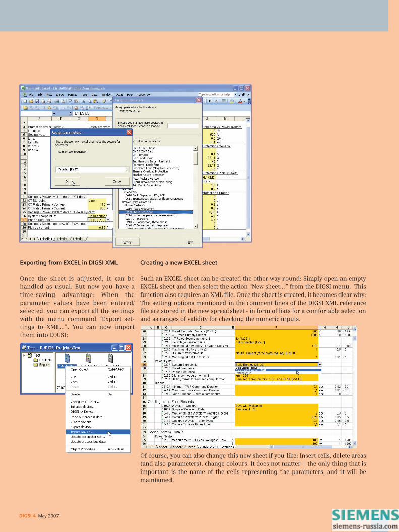
Exporting from EXCEL in DIGSI XML
Once the sheet is adjusted, it can behandled as usual. But now you have atime-saving advantage: When theparameter values have been entered/selected, you can export all the settingswith the menu command “Export set-tings to XML…”. You can now importthem into DIGSI:
Creating a new EXCEL sheet
Such an EXCEL sheet can be created the other way round: Simply open an emptyEXCEL sheet and then select the action “New sheet…” from the DIGSI menu. Thisfunction also requires an XML file. Once the sheet is created, it becomes clear why:The setting options mentioned in the comment lines of the DIGSI XML referencefile are stored in the new spreadsheet - in form of lists for a comfortable selectionand as ranges of validity for checking the numeric inputs.
Of course, you can also change this new sheet if you like: Insert cells, delete areas(and also parameters), change colours. It does not matter – the only thing that isimportant is the name of the cells representing the parameters, and it will bemaintained.
5DIGSI 4 May 2007

6 May 2007 DIGSI 4
Latest News
Full support of DigSilent
DigSilent have made adapters forall the SIPROTEC 4 devices, bymeans of which their networkcalculation software PowerWarecan be smoothly connected toDIGSI via the new DIGSI XMLinterface. Other manufacturerswith such software like Electro-con and IPS follow, too. For moredetails, please read the nextissue of the DIGSI 4 Notes.
Training courses (in Nuremberg) – an excerpt of the current programm
24.-25.05.07 Basics of Communication Networks and the Application in Power
18.-19.06.07 OMICRON test system
20.06.07 SIPROTEC - Communication-Workshop
21.-22.06.07 Basics of power quality
21.-22.06.07 Basics, application and commissioning of IEC61850 communication networks
25.-27.06.07 Application of Distance Relaying
02.-04.07.07 Application and Practice of Numerical Recording System SIMEAS R
02.-06.07.07 SIPROTEC 4 Protection Devices for Service Engineers
Find additional courses and information at www.ptd-training.com.
Discontinued devices
After 30 April 2007 the followingmodems for the remote operation ofSIPROTEC devices will no longer beavailable. Of course repairs can becarried out even after that date.
Discontinued Follow-up product7XV5800-3AA00 7XV5800-3BA007XV5800-7 no replacement!7XV5810-1 7XV5820-17XV5810-2 7XV5820-27XV5810-5 7XV5820-57XV5810-6 7XV5820-6
COMING SOON
IMPRESSUMEditorial & Publishing: Siemens AG; Power Transmission and Distribution (PTD): Gunther Reichenbach, Product Manager; Phone: +49 911 433-7442; E-mail: [email protected];Download/Info: www.siprotec.com; Support: www.siemens.com/ptd-support; Training: www.ptd-training.com; Layout: New Orange Design; Stylesheet: Publicis Kommunikations AgenturErlangen; Printed in Germany © Siemens AG 2007
QUESTIONS & ANSWERS
The normal green field of a CFC block indicates the sequence properties (priorityclass and sequence number). The block with the light green sequence field is the so-called “Predecessor for insert position”. This means that the next block which isincorporated, will be directly after this “predecessor” in the sequence, in the exam-ple this would be in position 16. If you whish to insert a block into the existing plan,mark the block which is directly before it in the sequence and the select the entry“Predecessor for insert position” from the menu “Edit”. This predecessor is alsoindicated in the status bar.
After an Upgrade of a device to the latest version (e.g. V4.50=> V4.62) and the sub-sequent translation of the CFC plans, the “old” devices (<=V4.50) put out an errormessage concerning the timer blocks which are allegedly in the wrong sequencelevel. What must I do?
After a device upgrade, replace all the timer blocks in the CFC plans by the new timerblocks from the block catalogue. Then update the blocks (“Options > Block types”)and translate the CFC plans.
I noticed that with DIGSI 4.80 no connection via modem to SIPROTEC V4 devices ispossible. What can I do?
This problem with the latest DIGSI version appears when the address of the opera-ting interface of service interface is not equal to 1. You can correct this by means ofthe Service Pack 1 for DIGSI 4.80, which you can download from the internet.
Exactly one block in the CFC plan shows a light green field. What does itmean?

DIGSI 4 Mai 2007
DIGSI 4 sNOTES
MM AA II 22 00 00 77 EE DD II TT II OO NN EE NN GG LL II SS HH AA NN DD GG EE RR MM AA NN
DEUTSCH
Viele Schutzeinstellprogramme ver-fügen über eine Exportschnittstelle,der Import aber wird meist gar nichtunterstützt. Dabei ist dieser gerade sointeressant: Daten aus anderen An-wendungen können – ggf. nach Kon-vertierung – in die Schutzbediensoft-ware eingelesen werden. Denn viel-fach sind diese Daten Ergebnisse vonaufwändigen Berechnungen z.B. inMS EXCEL-Einstellblättern oder Netz-kalkulationssoftware. Eine möglichsteinfache Übernahme spart hier Engi-neeringkosten und bewahrt natürlichauch vor Tippfehlern.
DIGSI spricht jetzt XML
INHALT
AKTUELLES
DIGSI spricht jetzt XML SEITE 1
Einblicke in das DIGSI
XML-Format SEITE 2
DIGSI 4.80 seit 3 Monaten
freigegeben SEITE 2
SIGRA 4 you SEITE 3
VORGESTELLT
Ganz versessen auf´s Messen SEITE 3
TIPPS & TRICKS
Einstellungen aus EXCEL
übernehmen SEITE 4
FRAGEN & ANTWORTEN SEITE 6
LETZTE MELDUNGEN SEITE 6
DEMNÄCHST SEITE 6
Mit der XML-Import- und Export-Schnittstelle von DIGSI zum Austausch von Datenvon SIPROTEC-Schutzgeräten eröffnen sich dem Anwender neue, kostensparendeMöglichkeiten: Über die Importschnittstelle kann der Anwender Daten aus anderenAnwendungen in DIGSI einlesen und Geräte auf diese Weise von außen parametrie-ren. Umgekehrt können die Einstelldaten in andere Anwendungen übertragen unddort weiterverarbeitet werden.
DIGSI 4.80 ist mit einer Import-/Ex-port-Schnittstelle ausgestattet, die denAustausch von Schutzeinstellungenund Signalverschaltungen in beidenRichtungen für alle Geräte der SIPRO-TEC 4 Familie erlaubt.
XML – universell, gut lesbar, struktu-riert, plattformunabhängig
Während sich die Datenausgabe dermeisten Einstellprogramme auf einfa-chen ASCII-Text beschränkt oder in Ein-zelfällen das Datenbankformat CSV be-dient, wurde bei DIGSI von Anfang andie Strategie verfolgt, ein universelles,plattformunabhängiges, verständlichesund langlebiges Format anzubieten,das auf der normierten Beschreibungs-sprache XML (extensible markup lang-uage) beruht. In DIGSI XML werdennormgemäß geeignete XML-Tags ange-boten, die zum Einen die Struktur desParametersatzes und zum Anderen dieBedeutung der Parameter wiederge-ben. So hat das DIGSI-XML-Format ausAnwendersicht einen entscheidendenVorteil: Es ist lesbar, ist mit wenigenEbenen gut strukturiert und kannleicht und schnell erlernt werden. Nurdas, was an der DIGSI-Oberfläche sicht-bar ist oder im Anhang eines jeden Ge-rätehandbuchs steht, geht in die Aus-tauschdatei ein: die Textelemente imParametrier-Dialog finden sich imDIGSI-XML-Code wieder.
2 Mai 2007 DIGSI 4
Einblicke in das DIGSI XML-Format
Da alle SIPROTEC-Parameter dank der sogenannten Direktadresse („DAdr“) eindeu-tig nummeriert sind, können die sprachab-hängigen Attribute wie der Name oder derDatentyp beim Import auch weggelassen
werden. Um z.B. den Wandlernennstrom auf 250 A zu ändern, genügt ein 5-zeiliger XML-“Schnippsel“ vollauf.
Signale mit ihrer Rangierung auf die Schnittstellen des Geräts können eben-falls exportiert werden. Und natürlich lassen sie sich per XML-Import auchvon außen rangieren, benutzerdefinierte Informationen wie Schaltbefehlekönnen angelegt und auch gelöscht werden.
AK TUELLES
DIGSI 4.80 seit 3 Monaten freigegeben
Seit 3 Monaten ist DIGSI in seiner neuesten Version 4.80 freigegeben. Dies sind die wichtigsten Neuerungen auf einen Blick:• Geräteparameter können jetzt mit DIGSI V4.80 im lesbaren XML-Format
exportiert und auch importiert werden. Somit können Änderungen oderErweiterungen an den Geräteparametern ohne DIGSI vorgenommen und erst später mit DIGSI in die Geräte übertragen werden.
• Die Einstellungen eines SIPROTEC 4-Gerätes können im XRIO-Format exportiert und dann im OMICRON-Prüfprogramm importiert werden.Siemens ist damit der erste Hersteller, der das neue XRIO-Format für alleSIPROTEC 4-Geräte unterstützt!
• In der Rangiermatrix können die Rangierungen spaltenweise zurückge-setzt werden. Hierdurch sparen Sie enorm Zeit, zum Beispiel beim Ent-fernen aller Rangierungen von der Systemschnittstelle.
• Beim Parametersatzvergleich werden jetzt auch die Eigenschaften von rangierten Informationen verglichen.
• In allen DIGSI-Programmen mit Druckfunktion erhalten Sie vor dem Druck eine Vorschau des zu erwartenden Ausdrucks. Dadurch können Sie die Menge und das Format abhängig vom Inhalt korrigieren.
• "Drucken in Datei" erfordert ab sofort nicht mehr die Installation eines spezifischen Druckertreibers.
• Parametersätze können direkt aus dem Manager ins Gerät übertragen werden: Sie selektieren das gewünschte Gerät im Manager und wählen die Funktion „DIGSI -> Gerät…“.

3DIGSI 4 Mai 2007
Im Messen ist er ein Meister, der SIMEAS P50: der neue Power Meter begeis-tert den Markt. Grund genug, ihn hier einmal vorzustellen.
Wenn Sie genau und zuverlässig wissen wollen, was in Ihrem Netz wirklichlos ist, ist der P50 genau richtig: günstig und gleichzeitig sehr leistungs-fähig ergänzt der neue Power Meter mit dem Produktnamen 7KG7750 dasSIMEAS Produktspektrum.
Mit einer beachtlichen Genauigkeit von99,8% werden Strom und Spannung ge-messen und daraus blitzschnell Messgrößenwie Frequenz, cosinus phi, Leistungen,Energiebezug bzw. –lieferung, Unsymme-trie, Harmonische oder der THD errechnet.
„What you see is what you need“ – Sie bestimmen, was angezeigt und wiees dargestellt wird.
Und wenn Sie noch mehr sehen wollen, Prozesssignale wie Temperatur,Druck oder Druckflussmenge? Dafür stehen optional Module mit analo-gen Eingängen zur Verfügung.
Überhaupt ist Flexibilität die Stärke des P50: • Das beginnt schon bei der Stromversorgung, einem Weitbereichsnetzteil,
das den Anschluss an jedes beliebige Stromnetz ermöglicht. • Mit der Unterstützung standardisierter Kommunikationsprotokolle lässt
sich der P50 ohne Probleme in Automatisierungs- und Leitsysteme inte-grieren.
• Der SIMEAS P50 misst jedes Netz, ob einphasige Netze, Stern- oder Drei-eck-Anschluss.
• Externe Wandler sind nicht nötig: Spannungs- und Stromeingänge sind variabel ausgelegt und messen selbst eine Überlast von 20% korrekt.
• Mit seinen geringen Maßen findet der P50 in jedem Schrank Platz. Für die Montage auf Hutschiene ist der P55 die richtige Variante.
• Die Parametrierung ist ausgesprochen einfach und kann direkt am Gerätoder mit einer kostenlos aus dem Internet erhältlichen Software erfolgen.
INFO
Leistungsmerkmale:• Hochgenaues Messen (3 Spannungen,
3 Ströme): 99,8%• Messeingänge für Spannung: 400V (L-L)
und 690V (L-N)• Messeingänge für Strom: 1A und 5A• Berechnung von mehr als 140 Messgrößen• RS485-Schnittstelle• Kommunikation über Profibus DP,
Modbus RTU/ASCII oder IEC60870-5-103• Weitbereichsstromversorgung mit
24 V – 220V DC oder mit 100 - 230V AC (50 oder 60Hz)
• Metallgehäuse 96x96mm• Optional: analoge und digitale Ein- und
Ausgänge• P50: Für Einbau im Schwenkrahmen,
großes Display, Schutzklasse Front (ge-mäß EN 60529): IP 41 oder IP 65 wählbar
• P55: Für Montage auf Hutschiene, statt Display mit Hutschienenhalterung, Schutz-klasse Front (gemäß EN 60529): IP 20
• Software kostenlos erhältlich
Bestelldaten:Bezeichnung: Power MeterMLFB: 7KG7750-0xA0x-0AA00 (P50)
7KG7755-0xA00-0AA00 (P55)
SIGRA 4 you
Mit der neuen Multimedia-Scheibe „SIGRA 4 you“ können Sie die weltbeste Software zurVisualisierung und Analyse von Störschrieben kennenlernen: Vom Darstellen und Aus-messen von Signalkurven über die Synchronisation von Störschrieben zur Offline-Fehler-ortung mit Daten von 2 Leitungsenden.
Bestellen Sie die CD kostenlos über die Bestellnummer E50417-A1176-C341
VORGESTELLT
Ganz versessen auf´s Messen

4 Mai 2007 DIGSI 4
Oft werden Berechnungen mit MS EXCELangestellt. Hierzu verwendet der An-wender standardisierte Einstellblättermit hinterlegten Formeln oder auf Basisvon EXCEL erstellte Wizards. Klar, dass erdie dabei entstehenden Daten möglichstnicht abtippen sondern direkt in DIGSIeinlesen will. Über die neue DIGSI XML-Schnittstelle ist das nun möglich: Miteinem EXCEL-AddIn, das seit Kurzem zurVerfügung steht, wird direkt aus demEinstellblatt der für DIGSI passende XML-Code erzeugt, der danach in DIGSI im-portiert werden kann.
Das EXCEL AddIn „DIGSI XML Interface“laden Sie kostenlos von der DownloadArea (www.siprotec.de) und kopieren esin das AddIn-Verzeichnis Ihrer Win-dows-Installation (z.B. C:\Documentsand Settings\User\Application Data\Micro-soft\AddIns). Nun zeigt die Menüleistevon EXCEL ein neues Menü mit dem Ti-tel „DIGSI“.
Gleich der erste Menüeintrag zeigt denSinn und Zweck des Makros: mittels„Exportieren in DIGSI XML…“ werdendie Einstellungen aus der geöffnetenEXCEL-Tabelle in XML-Code überge-führt, der von DIGSI importiert werdenkann. Das Makro muss dazu wissen,welche Tabellenzelle welchem Parame-ter eines Geräts zuzuordnen ist.
Parameter zuordnen
Für diese Zuordnung bedient sich das Makro eines Features von EXCEL: jedeZelle, die einen Parameter enthält, wird geeignet benannt. Mit der Funktion„Parameter zuordnen…“ aus dem Menü „DIGSI“ ist die Tabelle im Handum-drehen angepasst:Legen Sie zunächst das Gerät, für das das Einstellblatt verwendet wird, in DIGSIan, stellen Sie den Funktionsumfang entsprechend ein (lieber mehr als zu wenig)und exportieren Sie dann die Einstellungen aus dem Manager in eine XML-Datei.
TIPPS & TRICKS
Einstellungen aus EXCEL übernehmen
Wählen Sie nun in EXCELdie schon erwähnte Funk-tion „Parameter zuordnen…“aus dem Menü „DIGSI“. Indem nun erscheinendenDialog geben Sie die zuvoraus DIGSI exportierte XML-Referenzdatei an:
Nach Quittierung dieses Dialogs öffnet sich eine Liste aller Parameter, die dasMakro in der Referenzdatei gefunden hat. Doppelklick auf den Parameter undKlick in die entsprechende EXCEL-Zelle – schon ist die Zuordnung perfekt:

Aus EXCEL exportieren in DIGSI XML
Ist das Einstellblatt einmal angepasst,kann es wie bisher genutzt werden. Dochnun haben Sie den zeitsparenden Vorteil:Nach Eingabe bzw. Auswahl der Parame-terwerte werden alle Einstellungen perMenübefehl „Exportieren in DIGSI XML…“in eine Datei exportiert. Die können Sienun in DIGSI importieren:
Neues EXCEL-Einstellblatt erstellen
Umgekehrt lässt sich ein solches EXCEL-Einstellblatt erstellen: Einfach ein leeresEXCEL-Blatt öffnen und dann aus dem DIGSI-Menü die Aktion „Neues Einstell-blatt…“ auswählen. Auch diese Funktion verlangt nach einer XML-Datei. Ist dasEinstellblatt erzeugt, wird auch klar, warum: Die in den Kommentarzeilen derDIGSI-XML-Referenzdatei genannten Einstellmöglichkeiten sind in der neuenTabelle hinterlegt, als Listen zur bequemen Auswahl und als Gültigkeitsbereichezur Überprüfung der numerischen Eingaben.
Dieses neue Einstellblatt können Sie verändern wie Sie wollen: Zellen einfügen,Bereiche löschen (auch Parameter), Farben ändern. Egal – einzig wichtig ist dieBenennung der die Parameter repräsentierenden Zellen, und die bleibt erhalten.
5DIGSI 4 Mai 2007

6 Mai 2007 DIGSI 4
Letzte Meldung
Volle Unterstützung von DigSilent
Die Firma DigSilent hat für alleSIPROTEC 4-Geräte Adapter er-stellt, mit deren Hilfe ihre Netz-berechnungssoftware PowerWareüber die neue DIGSI XML-Schnitt-stelle nahtlos an DIGSI ange-schlossen werden kann. Auchandere Hersteller solcher Soft-ware wie Electrocon und IPS fol-gen. Mehr dazu in der nächstenAusgabe der DIGSI 4 Notes.
Trainingsangebote (Ort: Nürnberg) – ein Auszug aus dem aktuellen Programm
21.-23.05.07 DIGSI 4 - Aufbaukurs - Schutz- und Leittechnische Funktionen
11.-13.06.07 DIGSI 4 - Grundkurs - Schutz- und Leittechnische Funktionen
11.-15.06.07 Schutztechnik für Übertragungsnetze
12.-13.06.07 SICAM PAS - Automatisierung mit CFC und ST
13.-15.06.07 Praktische Anwendung des Differentialschutzes
14.-15.06.07 DIGSI 4 - Konfiguration von Stationen und Geräten mit IEC 61850
25.06.07 SIPROTEC - Kommunikations-Workshop
25.-29.06.07 SICAM PAS - Parametrierung
Weitere Kurse und Information unter www.ptd-training.de.
Auslaufende Geräte
Nach dem 30. April 2007 werden fol-gende Modems zur Fernbedienungder SIPROTEC-Geräte nicht mehr ge-liefert. Reparaturen werden selbstver-ständlich auch danach vorgenom-men:
Auslauftyp Nachfolgeprodukt7XV5800-3AA00 7XV5800-3BA007XV5800-7 Kein Ersatz!7XV5810-1 7XV5820-17XV5810-2 7XV5820-27XV5810-5 7XV5820-57XV5810-6 7XV5820-6
DEMNÄCHST
IMPRESSUMEditorial & Publishing: Siemens AG; Power Transmission and Distribution (PTD): Gunther Reichenbach, Produktmanager; Telefon: +49 911 433-7442; E-mail: [email protected];Download/Info: www.siprotec.de; Support: www.siemens.com/ptd-support; Training: www.ptd-training.de; Layout: New Orange Design; Stylesheet: Publicis Kommunikations Agentur Erlangen; Printed in Germany © Siemens AG 2007
FRAGEN & ANT WORTEN
Das normalgrüne Feld eines CFC-Bausteins zeigt die Ablaufeigenschaften(Ablaufebene und Ablaufnummer) an. Der Baustein, dessen Ablauffeld hellgrüngefärbt dargestellt wird, ist der so genannte „Vorgänger für Einbauposition“. Dasbedeutet, dass der nächste Baustein, der eingefügt wird, in der Ablaufreihenfolgedirekt nach diesem „Vorgänger“ ablaufen wird, im gezeigten Beispiel also anPosition 16. Wollen Sie also in einem bestehenden Plan einen Baustein einfügen,markieren Sie zunächst den in der Reihenfolge direkt davor laufenden Baustein undwählen Sie dann den Eintrag „Vorgänger für Einbauposition“ aus dem Menü„Bearbeiten“. Dieser Vorgänger wird übrigens auch in der Statuszeile gezeigt.
Nach einem Upgrade eines Gerätes auf eine aktuellere Version (z.B. V4.50 => V4.62)und anschließendem Übersetzen der CFC-Pläne kommt es bei "alten" Geräten(<=V4.50) zu einer Fehlermeldung bezüglich der Timer-Bausteine, welche sichangeblich in der falschen Ablaufebene befinden Was muss ich tun?
Ersetzen Sie nach dem Geräteupgrade alle Timer-Bausteine in den CFC-Plänen mitneuen Timer-Bausteinen aus dem Bausteinkatalog. Anschließend aktualisieren Siealle Bausteine („Extras > Bausteintypen“) und übersetzen die CFC-Pläne.
Ich habe festgestellt, dass mit DIGSI 4.80 zu SIPROTEC V4-Geräten über Modemkeine Verbindung möglich ist. Was kann ich tun?
Dieses Problem mit der neuen DIGSI-Version besteht, wenn die Adresse derBedienschnittstelle oder Service-Schnittstelle ungleich 1 ist. Eine Behebung ist mitdem Service Pack 1 für DIGSI 4.80 möglich, das Sie von der Download Area laden.
Immer genau ein Baustein im CFC-Plan zeigt ein hellgrünes Feld. Was istseine Bedeutung?„BOOL_TO_CO“?