digitrip retrofit system for allis-chalmers la-1600 f fused ... -...
TRANSCRIPT

Effective July 2010Supersedes IL 33-A4C-1 Dated 10/02Instruction Leaflet IL 33-A4C-2
Digitrip Retrofit System for Allis-Chalmers LA-1600 F Fused Breakers

2
Instruction Leaflet IL 33-A4C-2Effective July 2010
Digitrip Retrofit System for Allis-Chalmers LA-1600 F Fused Breakers
EAton CoRpoRAtIon www.eaton.com
WARNINGPOWER CIRCUIT BREAKERS ARE EQUIPPED WITH HIGH SPEED, HIGH ENERGY OPERATING MECHANISMS. THE BREAKERS AND THEIR ENCLOSURES ARE SIGNED WITH SEVERAL BUILT-IN INTERLOCKS AND SAFETY FEATURES INTENDED TO PROVIDE SAFE AND PROPER OPERATING SEQUENCES. TO PROVIDE MAXIMUM PROTECTION FOR PERSONNEL ASSOCIATED WITH THE INSTALLATION, OPERATION, AND MAINTENANCE OF THESE BREAKERS, THE FOLLOWING PRACTICES MUST BE FOLLOWED. FAILURE TO FOLLOW THESE PRACTICES MAY RESULT IN DEATH, PERSONAL INJURY, OR PROPERTY DAMAGE.
Safety Precautions
• Periodic testing of this device is required (see Step 13 Testing the Breaker for test procedures).
• Only qualified persons, as defined in the National Electric Code, who are familiar with the installation and maintenance of power circuit breakers and their associated switchgear assemblies should perform any work associated with these breakers.
• Completely read and understand all instructions before attempting any installation, operation, maintenance, or modification of these breakers.
• Always turn off and lock out the power source feeding the breaker prior to attempting any installation, maintenance, or modi-fication of the breaker. Do not use the circuit breaker as the sole means for isolating a high voltage circuit. Follow all lockout and tagging rules of the National Electric Code and all other applicable codes, regulations, and work rules.
• Do not work on a closed breaker or a breaker with the closing springs charged. Trip (open) the breaker and be sure the stored energy springs are discharged before performing any work. The breaker may trip open or the charging springs may discharge, causing crushing or cutting injuries.
• For drawout breakers, trip (open), and then remove the breaker to a well-lit work area before beginning work.
• Do not perform any maintenance: including breaker charging, clos-ing, tripping, or any other function which could cause significant movement of the breaker while it is on the extension rails. Doing so may cause the breaker to slip from the rails and fall, potentially causing severe personal injury to those in the vicinity.
• Do not leave the breaker in an intermediate position in the switch-gear cell. Always leave it in the connected, disconnected, or (optional) test position. Failure to do so could lead to improper positioning of the breaker and flashover, causing death, serious personal injury, and / or property damage.
• Do not defeat any safety interlock. Such interlocks are intended to protect personnel and equipment from damage due to flash-over and exposed contacts. Defeating an interlock could lead to death, severe personal injury, and / or property damage
Instruction Leaflet IL 33-A4C-2Effective July 2010
Digitrip Retrofit System for Allis-ChalmersLA-1600 F Fused Breakers
EATON CORPORATION www.eaton.com 3
Description
Introduction .......................................................... 6Step 1: General Breaker Preparation .............. 7Step 2: Removing the Original
Components ......................................... 8Step 3: Modifying the Phase 3 Phase
Barriers ............................................... 10Step 4: Installing the Reset Link Assembly .. 11Step 5: Preparing the DTA Assembly for
Installation .......................................... 12Step 6: Installing the DTA Assembly ............. 15Step 7: Setting the Gap and Cage Height ..... 17Step 8: Installing the Trip Unit ........................ 18Step 9: Installing the External
Harness ............................................... 22Step 10: Installing the Breaker Mounted
CPT Module......................................... 25Step 11: Installing the Sensors ........................ 30Step 12: Final Wiring and Reinstalling the
Original BreakerComponents ....................................... 31
Step 13: Testing the Breaker ............................ 32Step 14: Mounting the Cell Harness ................ 33Step 15: Installing the Retrofitted Breaker
in the Cell ............................................ 33
CONTENTS
Figures
1. Overview: Original ComponentsRemoved from the Breaker. ......................... 8
2. Original Components Removed andSaved for Reinstallation. .............................. 8
3. Reset Spring, Release Magnet Spacer,Threaded Shaft, and Nylon Nut ReinstalledUsing the Supplied Flat Washers. ................ 9
4. Original Components Removed andScrapped. ..................................................... 9
5. Overview: Modifying the Phase 3 PhaseBarriers. ....................................................... 10
6. Trimming the Phase 3 Phase Barriers. ....... 10
7. Replacement of the Trip ShaftInterlock Pin. ............................................... 10
8. Interconnecting Phase BarrierReinstalled in the Breaker. .......................... 10
9. Overview: Reset Link Assembly Installedon the Closing Mechanism......................... 11
10. Reset Link Assembly Installed on theBreaker Pole Shaft Wrist Pin. ..................... 11
11. Overview: DTA Assembly Ready forInstallation in the Breaker. .......................... 12
12. Sensor Harness Installed on the Aux.CT Module. ................................................. 12
13. Aux. CT Module Pigtail Secured to thePanduit Cable Tie Mount. ........................... 12
14. Aux. CT Module Mounted to the DTAAssembly and Sensor Harness Groundsecured to the Aux. CT Module. ................ 13
Digitrip Retrofit Systemfor Allis-ChalmersLA-1600 F FusedBreakers

Digitrip Retrofit System for Allis-ChalmersLA-1600 F Fused Breakers
Instruction Leaflet IL 33-A4C-2Effective July 2010
4 EATON CORPORATION www.eaton.com
15. DTA Wires Connected to the Aux. CTModule terminals. ....................................... 13
16. PT Label Flag Removed from thePT Module. ................................................. 13
17. Insulation Barrier and Panduit Cable TieMount Installed on the PT Module. ............ 14
18. PT Module Assembly Installed on theDTA Assembly. ........................................... 14
19. Microswitch Installed on the AuxiliarySwitch Mounting Bracket. .......................... 14
20. Auxiliary Switch Assembly Installed onthe DTA Assembly. ..................................... 14
21. Overview: DTA Assembly Installed inthe Breaker. ................................................. 15
22. Correct Positioning of the DTA AssemblyFront Mounting Bracket and AuxiliarySwitch Arm. ................................................ 15
23. Correct Positioning of the DTA Assemblyto Provide the Required Gap and to Clearthe Manual Trip Bar. .................................... 16
24. PT Wires Connected to the BottomCurrent Transformers. ................................ 16
25. PT Warning Label Installed on the Breaker. 1626. Sensor Harness Routed to the Back of
the Breaker. ................................................. 17
27. DTA Installed in the Breaker. ...................... 1728. Overview: DTA Gap and Cage Height
Adjusted. ..................................................... 17
29. Adjusting the Cage Height. ........................ 1730. Overview: Trip Unit Installed on the
Breaker. ....................................................... 18
31. Trip Unit Mounting Bracket Installed onthe Minibox. ................................................ 18
32. Location of the “Jacking” Screws. ............. 19
33. Insulation Barrier and Panduit Cable TieMounts Installed on the Minibox. ............... 19
34. Communications Harness Connectedto the Trip Unit. ........................................... 19
35. Location of the Edge Card Receptacle,Communications Harness Connector,and ATR in the Minibox. ............................. 20
36. Trip Unit Installed in the Minibox. ............... 2037. Jacking Screw Instructions. ....................... 20
38. Rating Plug and Trip Unit Cover Installed. . 2139. Trip Unit Assembly Installed on the
Breaker. ....................................................... 21
40. Digitrip Retrofit Label Installed on theBreaker Face Plate. .................................... 21
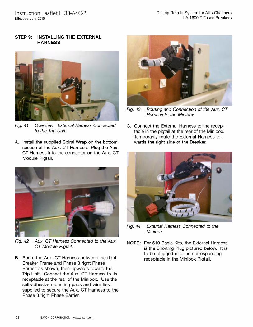
41. Overview: External Harness Connectedto the Trip Unit. ........................................... 22
42. Aux. CT Harness Connected to theAux. CT Module Pigtail. .............................. 22
43. Routing and Connection of the Aux.CT Harness to the Minibox. ....................... 22
44. External Harness Connected to theMinibox. ...................................................... 22
45. 510 Basic Kit External HarnessShorting Plug. ............................................. 23
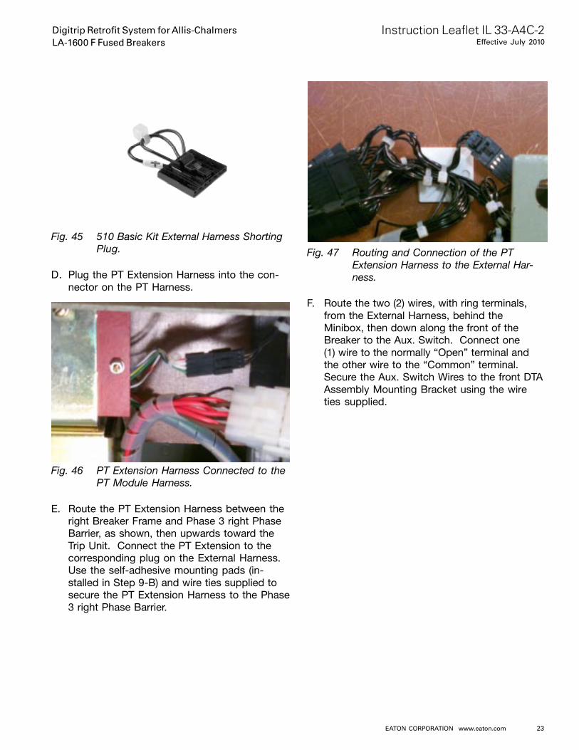
46. PT Extension Harness Connected tothe PT Module Harness. ............................ 23
47. Routing and Connection of the PTExtension Harness to the ExternalHarness. ...................................................... 23
48. Routing and Connection of the AuxiliarySwitch Wires to the Auxiliary Switch. ......... 24
49. External Harness Secured to the Minibox. 2450. Overview: CPT Module Installed on the
Breaker. ....................................................... 2551. Drilling Plan “A”. .......................................... 2552. Fuse Clips and Spade Connector
Removed from the CPT. ............................. 2553. Breaker Mounted CPT Installed on the
CPT Mounting Bracket. .............................. 26
54. CPT Assembly Installed on the Breaker. ... 2655. CPT Harness Connected to the
External Harness. ....................................... 26
56. Load and Line Sides of the HV Wires. ....... 2757. Suggested Location for the HV Fuses. ..... 2758. Load Side HV Wires and CPT Harness
Connected to the Terminals of the CPTModule. ....................................................... 28
59. Finger Safe Covers Installed on the CPT. .. 28
60. HV Wires Connected to the CurrentLimiting Fuse Connectors. ......................... 29
61. HV Fuses Secured to the Breaker. ............ 29
Instruction Leaflet IL 33-A4C-2Effective July 2010
Digitrip Retrofit System for Allis-ChalmersLA-1600 F Fused Breakers
EATON CORPORATION www.eaton.com 5
62. CPT Voltage Labels Supplied with theCPT Kit. ....................................................... 29
63. CPT Voltage Label Installed on the TripUnit Insulation Barrier. ................................ 29
64. Overview: Sensors Installed on theBreaker. ....................................................... 30
65. Sensor Installed on the BreakerConnector and Held in Place by theSensor Spacers. ......................................... 30
66. Sensor Harness Connected to theSensors. ...................................................... 30
67. Overview: All Harness and WiresSecured in the Breaker. .............................. 31
68. Breaker Ready for Testing. ......................... 3169. Retrofit Components .................................. 38
Tables 1. Available Retrofit Kits ................................... 6 2. CPT Low Voltage Taps for Standard .............
and Special Order CPTs(After Removing Fuse Clips) ...................... 26
3. CPT High Voltage Taps for Standardand Special Order CPTs ............................. 27
4. Sensor Taps Rating .................................... 30 5. Torque Values for General Mounting and
Screw Size Conversion .............................. 37 6. Torque Values for Copper BUS
Connectors ................................................. 37
6
Instruction Leaflet IL 33-A4C-2Effective July 2010
Digitrip Retrofit System for Allis-Chalmers LA-1600 F Fused Breakers
EAton CoRpoRAtIon www.eaton.com
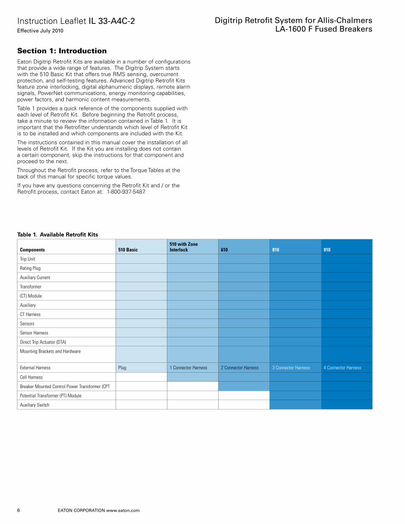
Section 1: IntroductionEaton Digitrip Retrofit Kits are available in a number of configurations that provide a wide range of features. The Digitrip System starts with the 510 Basic Kit that offers true RMS sensing, overcurrent protection, and self-testing features. Advanced Digitrip Retrofit Kits feature zone interlocking, digital alphanumeric displays, remote alarm signals, PowerNet communications, energy monitoring capabilities, power factors, and harmonic content measurements.
Table 1 provides a quick reference of the components supplied with each level of Retrofit Kit. Before beginning the Retrofit process, take a minute to review the information contained in Table 1. It is important that the Retrofitter understands which level of Retrofit Kit is to be installed and which components are included with the Kit.
The instructions contained in this manual cover the installation of all levels of Retrofit Kit. If the Kit you are installing does not contain a certain component, skip the instructions for that component and proceed to the next.
Throughout the Retrofit process, refer to the Torque Tables at the back of this manual for specific torque values.
If you have any questions concerning the Retrofit Kit and / or the Retrofit process, contact Eaton at: 1-800-937-5487.
Table 1. Available Retrofit Kits
Components 510 Basic510 with Zone Interlock 610 810 910
Trip Unit
Rating Plug
Auxiliary Current
Transformer
(CT) Module
Auxiliary
CT Harness
Sensors
Sensor Harness
Direct Trip Actuator (DTA)
Mounting Brackets and Hardware
External Harness Plug 1 Connector Harness 2 Connector Harness 3 Connector Harness 4 Connector Harness
Cell Harness
Breaker Mounted Control Power Transformer (CPT
Potential Transformer (PT) Module
Auxiliary Switch
Instruction Leaflet IL 33-A4C-2Effective July 2010
Digitrip Retrofit System for Allis-ChalmersLA-1600 F Fused Breakers
EATON CORPORATION www.eaton.com 7
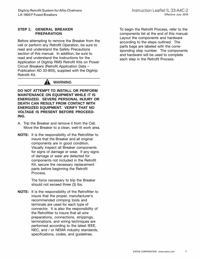
STEP 1: GENERAL BREAKERPREPARATION
Before attempting to remove the Breaker from thecell or perform any Retrofit Operation, be sure toread and understand the Safety Precautionssection of this manual. In addition, be sure toread and understand the Instructions for theApplication of Digitrip RMS Retrofit Kits on PowerCircuit Breakers (Retrofit Application Data –Publication AD 33-855), supplied with the DigitripRetrofit Kit.
To begin the Retrofit Process, refer to thecomponents list at the end of this manual.Layout the components and hardwareaccording to the steps outlined. Theparts bags are labeled with the corre-sponding step number. The componentsand hardware will be used to completeeach step in the Retrofit Process.
WARNING
DO NOT ATTEMPT TO INSTALL OR PERFORMMAINTENANCE ON EQUIPMENT WHILE IT ISENERGIZED. SEVERE PERSONAL INJURY ORDEATH CAN RESULT FROM CONTACT WITHENERGIZED EQUIPMENT. VERIFY THAT NOVOLTAGE IS PRESENT BEFORE PROCEED-ING.
A. Trip the Breaker and remove it from the Cell.Move the Breaker to a clean, well-lit work area.
NOTE: It is the responsibility of the Retrofitter toinsure that the Breaker and all originalcomponents are in good condition.Visually inspect all Breaker componentsfor signs of damage or wear. If any signsof damage or wear are detected forcomponents not included in the RetrofitKit, secure the necessary replacementparts before beginning the RetrofitProcess.
The force necessary to trip the Breakershould not exceed three (3) lbs.
NOTE: It is the responsibility of the Retrofitter toinsure that the proper, manufacturer’srecommended crimping tools andterminals are used for each type ofconnector. It is also the responsibility ofthe Retrofitter to insure that all wirepreparations, connections, strippings,terminations, and wiring techniques areperformed according to the latest IEEE,NEC, and / or NEMA industry standards,specifications, codes, and guidelines.

Digitrip Retrofit System for Allis-ChalmersLA-1600 F Fused Breakers
Instruction Leaflet IL 33-A4C-2Effective July 2010
8 EATON CORPORATION www.eaton.com
STEP 2: REMOVING THE ORIGINALCOMPONENTS
Fig. 1 Overview: Original Components Re-moved from the Breaker.
Refer to the Allis-Chalmers LA-1600 F InstructionManual, originally supplied with the Breaker, toperform the following procedures.
A. If equipped, remove and save the hardwaresecuring the Closing Handle to the Breaker.Remove and save the Closing Handle.
B. Remove and save the hardware securing theFace Plate to the Breaker. Remove and savethe Face Plate.
C. Remove and save the hardware securing theBlown Fuse Indicator wires to the top BreakerConnectors (Stabs). Remove and save thehardware securing the Current Limiting FuseAssembly to the top Breaker Connectors.Remove the Current Limiting Fuse Assemblyand set it behind the Breaker. Note that no
other wires except the Blown Fuse Indicatorwires have to be disconnected from theCurrent Limiting Fuse Assembly.
D. Remove and save the hardware securing thePrimary Disconnects (Finger Clusters) to thebottom Breaker Connectors (Stabs). Removeand save the Primary Disconnects.
E. Remove and save the wing nuts securing theArc Chute Retaining Bar. Remove and savethe Arc Chute Retaining Bar and the ArcChutes.
F. Remove and save the plastic rivets securingthe Interconnecting Phase Barrier in theBreaker. After noting its orientation, removethe Interconnecting Phase Barrier through theright side of the Breaker.
G. Note the orientation of the two (2) Phase 3(right) Phase Barriers. Remove all the PhaseBarriers from the Breaker.
Fig. 2 Original Components Removed andSaved for Reinstallation.
H. Remove and scrap the hardware securing theStatic Trip Device (Trip Unit) and mountingbracket to the Breaker. Remove and scrap theStatic Trip Device, mounting bracket, andassociated wiring.
Instruction Leaflet IL 33-A4C-2Effective July 2010
Digitrip Retrofit System for Allis-ChalmersLA-1600 F Fused Breakers
EATON CORPORATION www.eaton.com 9
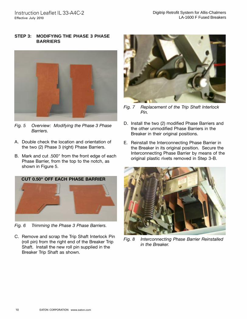
I. Remove the hardware securing the ReleaseMagnet (Direct Trip Actuator) and mountingbracket to the Breaker. Remove and scrapthe Release Magnet, mounting bracket, andbottom mounting hardware (flat head screw,washers, and nut). Save the nylon nut, resetspring, spacer, and top mounting hardware(thread shaft washers, and Nylok nut).
J. Reinstall the Reset Spring. Reinstall theRelease Magnet Spacer, threaded shaft, andnylon nut removed in Step 2-F. To make upfor the thickness of the removed ReleaseMagnet, install the (5) 0.313" flat washerssupplied on the threaded shaft before install-ing the nylon nut.
If the Breaker being Retrofitted is equippedwith an Under Voltage Mechanism, use the(2) .250" washers supplied to make up for thespace left by removing the Release magnet.
Fig. 3 Reset Spring, Release Magnet Spacer,Threaded Shaft, and Nylon Nut Rein-stalled Using the Supplied Flat Washers.
K. Remove and scrap the hardware securing theSensors to the Breaker. Remove and scrapthe Sensors, Insulating Rings, InsulatingSpacers, and associated wiring.
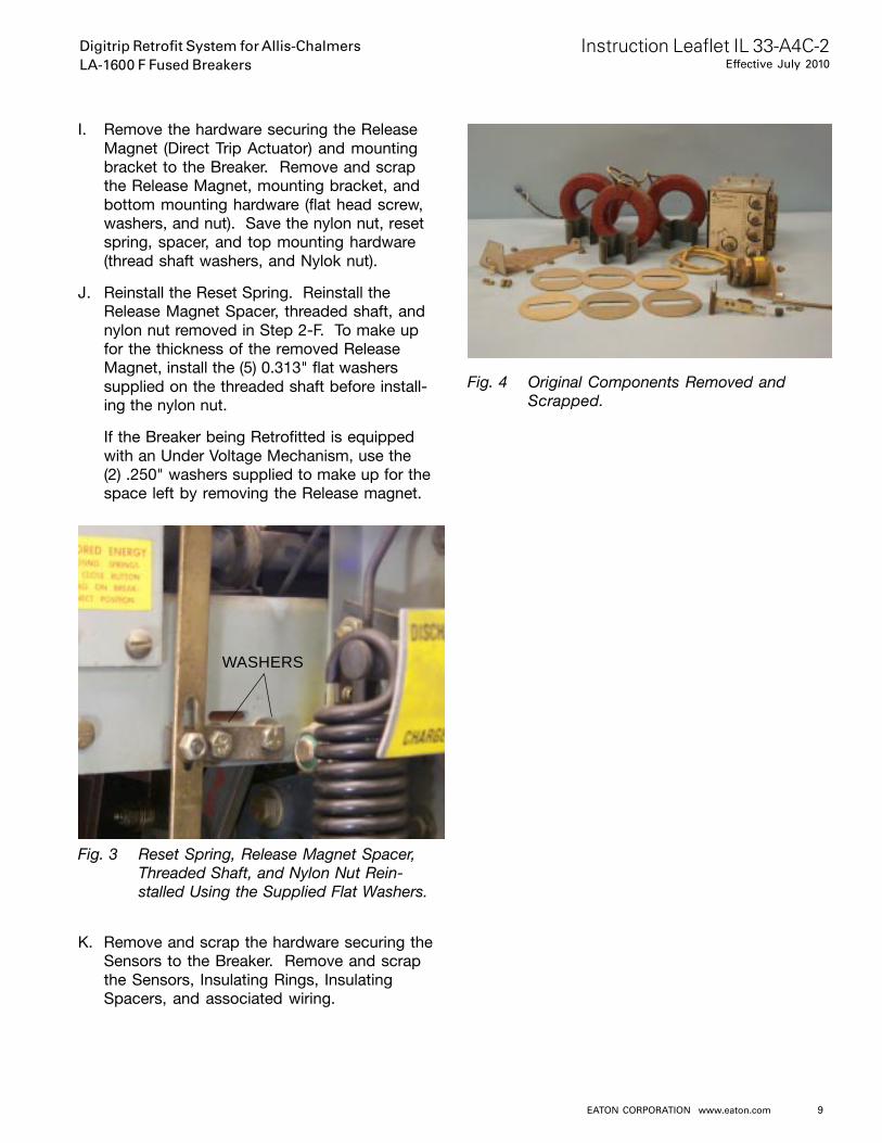
Fig. 4 Original Components Removed andScrapped.
WASHERS
Digitrip Retrofit System for Allis-ChalmersLA-1600 F Fused Breakers
Instruction Leaflet IL 33-A4C-2Effective July 2010
10 EATON CORPORATION www.eaton.com
STEP 3: MODIFYING THE PHASE 3 PHASEBARRIERS
Fig. 7 Replacement of the Trip Shaft InterlockPin.
D. Install the two (2) modified Phase Barriers andthe other unmodified Phase Barriers in theBreaker in their original positions.
E. Reinstall the Interconnecting Phase Barrier inthe Breaker in its original position. Secure theInterconnecting Phase Barrier by means of theoriginal plastic rivets removed in Step 3-B.
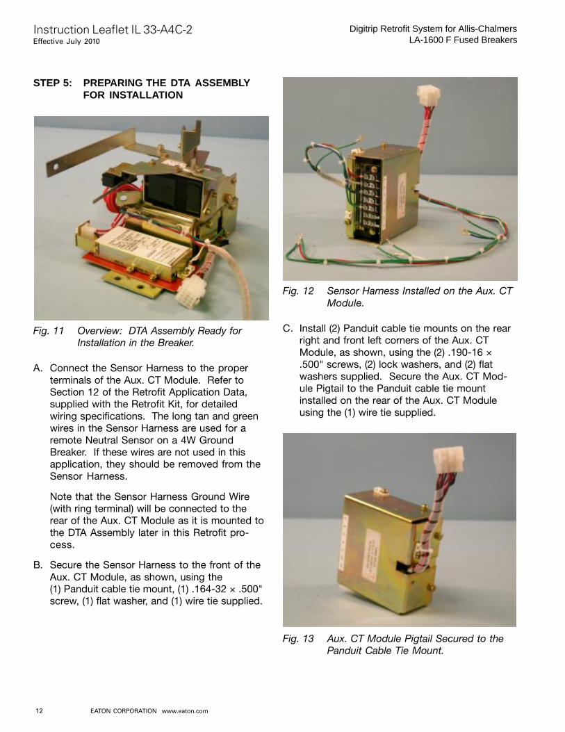
Fig. 5 Overview: Modifying the Phase 3 PhaseBarriers.
A. Double check the location and orientation ofthe two (2) Phase 3 (right) Phase Barriers.
B. Mark and cut .500" from the front edge of eachPhase Barrier, from the top to the notch, asshown in Figure 5.
Fig. 6 Trimming the Phase 3 Phase Barriers.
C. Remove and scrap the Trip Shaft Interlock Pin(roll pin) from the right end of the Breaker TripShaft. Install the new roll pin supplied in theBreaker Trip Shaft as shown.
CUT 0.50" OFF EACH PHASE BARRIER
Fig. 8 Interconnecting Phase Barrier Reinstalledin the Breaker.

Instruction Leaflet IL 33-A4C-2Effective July 2010
Digitrip Retrofit System for Allis-ChalmersLA-1600 F Fused Breakers
EATON CORPORATION www.eaton.com 11
STEP 4: INSTALLING THE RESET LINKASSEMBLY
Fig. 9 Overview: Reset Link Assembly Installedon the Closing Mechanism.
NOTE: On some LA-1600 F breakers, the originalWrist Pin connecting the Insulation Link tothe Breaker Pole Shaft is long enough toaccept the new Reset Link, flat washerand Tru-arc lock ring and does not haveto be replaced. If this is the case with theBreaker being Retrofitted, jump ahead toStep 4-D.
A. Remove and scrap the Wrist Pin and hardwarethat connects the Insulation Link to theBreaker Pole Shaft for Phase 3.
B. Install (1) Tru-arc lock ring on the new WristPin. Completely insert the Wrist Pin into theInsulation Link and Breaker Pole Shaft fromthe left side.
C. Install (2) 0.375" flat washers, then the ResetLink Assembly onto the Wrist Pin as shown.Install (1) Tru-arc lock ring on the right end ofthe Wrist Pin. Note that the Reset Link shouldmove freely on the Wrist Pin.
Fig. 10 Reset Link Assembly Installed on theBreaker Pole Shaft Wrist Pin.
Digitrip Retrofit System for Allis-ChalmersLA-1600 F Fused Breakers
Instruction Leaflet IL 33-A4C-2Effective July 2010
12 EATON CORPORATION www.eaton.com
STEP 5: PREPARING THE DTA ASSEMBLYFOR INSTALLATION
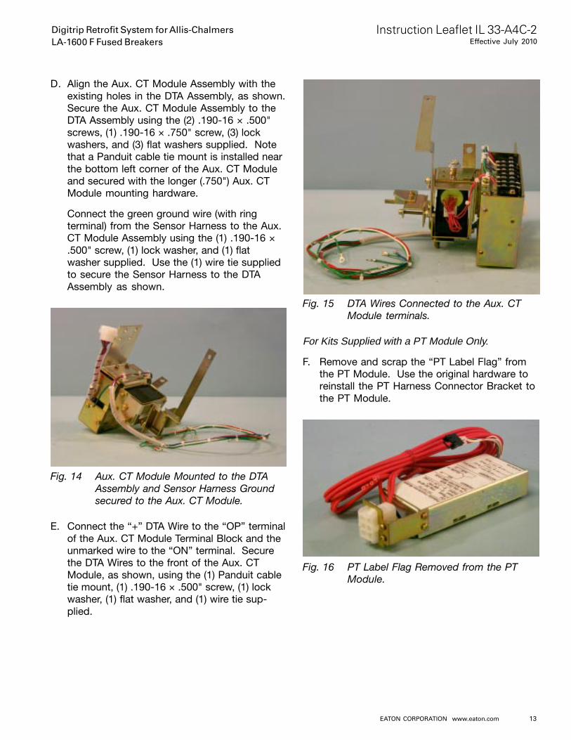
Fig. 11 Overview: DTA Assembly Ready forInstallation in the Breaker.
A. Connect the Sensor Harness to the properterminals of the Aux. CT Module. Refer toSection 12 of the Retrofit Application Data,supplied with the Retrofit Kit, for detailedwiring specifications. The long tan and greenwires in the Sensor Harness are used for aremote Neutral Sensor on a 4W GroundBreaker. If these wires are not used in thisapplication, they should be removed from theSensor Harness.
Note that the Sensor Harness Ground Wire(with ring terminal) will be connected to therear of the Aux. CT Module as it is mounted tothe DTA Assembly later in this Retrofit pro-cess.
B. Secure the Sensor Harness to the front of theAux. CT Module, as shown, using the(1) Panduit cable tie mount, (1) .164-32 × .500"screw, (1) flat washer, and (1) wire tie supplied.
Fig. 12 Sensor Harness Installed on the Aux. CTModule.
C. Install (2) Panduit cable tie mounts on the rearright and front left corners of the Aux. CTModule, as shown, using the (2) .190-16 ×.500" screws, (2) lock washers, and (2) flatwashers supplied. Secure the Aux. CT Mod-ule Pigtail to the Panduit cable tie mountinstalled on the rear of the Aux. CT Moduleusing the (1) wire tie supplied.
Fig. 13 Aux. CT Module Pigtail Secured to thePanduit Cable Tie Mount.
Instruction Leaflet IL 33-A4C-2Effective July 2010
Digitrip Retrofit System for Allis-ChalmersLA-1600 F Fused Breakers
EATON CORPORATION www.eaton.com 13
D. Align the Aux. CT Module Assembly with theexisting holes in the DTA Assembly, as shown.Secure the Aux. CT Module Assembly to theDTA Assembly using the (2) .190-16 × .500"screws, (1) .190-16 × .750" screw, (3) lockwashers, and (3) flat washers supplied. Notethat a Panduit cable tie mount is installed nearthe bottom left corner of the Aux. CT Moduleand secured with the longer (.750") Aux. CTModule mounting hardware.
Connect the green ground wire (with ringterminal) from the Sensor Harness to the Aux.CT Module Assembly using the (1) .190-16 ×.500" screw, (1) lock washer, and (1) flatwasher supplied. Use the (1) wire tie suppliedto secure the Sensor Harness to the DTAAssembly as shown.
Fig. 14 Aux. CT Module Mounted to the DTAAssembly and Sensor Harness Groundsecured to the Aux. CT Module.
E. Connect the “+” DTA Wire to the “OP” terminalof the Aux. CT Module Terminal Block and theunmarked wire to the “ON” terminal. Securethe DTA Wires to the front of the Aux. CTModule, as shown, using the (1) Panduit cabletie mount, (1) .190-16 × .500" screw, (1) lockwasher, (1) flat washer, and (1) wire tie sup-plied.
Fig. 15 DTA Wires Connected to the Aux. CTModule terminals.
For Kits Supplied with a PT Module Only.
F. Remove and scrap the “PT Label Flag” fromthe PT Module. Use the original hardware toreinstall the PT Harness Connector Bracket tothe PT Module.
Fig. 16 PT Label Flag Removed from the PTModule.
Digitrip Retrofit System for Allis-ChalmersLA-1600 F Fused Breakers
Instruction Leaflet IL 33-A4C-2Effective July 2010
14 EATON CORPORATION www.eaton.com
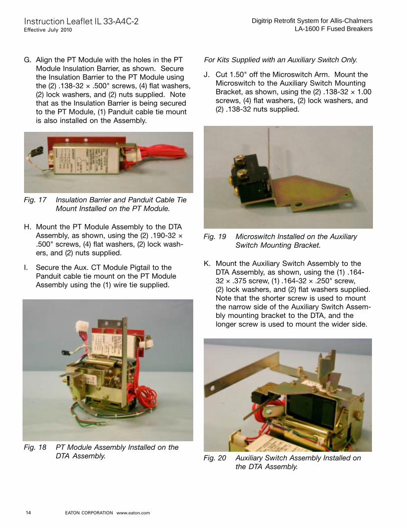
G. Align the PT Module with the holes in the PTModule Insulation Barrier, as shown. Securethe Insulation Barrier to the PT Module usingthe (2) .138-32 × .500" screws, (4) flat washers,(2) lock washers, and (2) nuts supplied. Notethat as the Insulation Barrier is being securedto the PT Module, (1) Panduit cable tie mountis also installed on the Assembly.
For Kits Supplied with an Auxiliary Switch Only.
J. Cut 1.50" off the Microswitch Arm. Mount theMicroswitch to the Auxiliary Switch MountingBracket, as shown, using the (2) .138-32 × 1.00screws, (4) flat washers, (2) lock washers, and(2) .138-32 nuts supplied.
Fig. 17 Insulation Barrier and Panduit Cable TieMount Installed on the PT Module.
H. Mount the PT Module Assembly to the DTAAssembly, as shown, using the (2) .190-32 ×.500" screws, (4) flat washers, (2) lock wash-ers, and (2) nuts supplied.
I. Secure the Aux. CT Module Pigtail to thePanduit cable tie mount on the PT ModuleAssembly using the (1) wire tie supplied.
Fig. 18 PT Module Assembly Installed on theDTA Assembly.
Fig. 19 Microswitch Installed on the AuxiliarySwitch Mounting Bracket.
K. Mount the Auxiliary Switch Assembly to theDTA Assembly, as shown, using the (1) .164-32 × .375 screw, (1) .164-32 × .250" screw,(2) lock washers, and (2) flat washers supplied.Note that the shorter screw is used to mountthe narrow side of the Auxiliary Switch Assem-bly mounting bracket to the DTA, and thelonger screw is used to mount the wider side.
Fig. 20 Auxiliary Switch Assembly Installed onthe DTA Assembly.

Instruction Leaflet IL 33-A4C-2Effective July 2010
Digitrip Retrofit System for Allis-ChalmersLA-1600 F Fused Breakers
EATON CORPORATION www.eaton.com 15
STEP 6: INSTALLING THE DTA ASSEMBLY
Fig. 21 Overview: DTA Assembly Installed in theBreaker.
A. Remove and scrap the nut securing the wash-ers and spring to the Reset Shaft. Hold thespring and washers in place on the ResetShaft. As the DTA Assembly is being in-stalled, align the Reset Shaft with the slot inthe Reset Arm.
B. Temporarily mount the DTA Assembly, asshown, to the existing holes in the rightBreaker Frame using the (2) .250-20 × .750bolts and (2) lock washers supplied.
NOTE: As the DTA Assembly is being tempo-rarily mounted to the right Breaker Frame,the DTA front Mounting Bracket MUST beon the outside of the front Breaker Frame,the DTA Trip Finger MUST be in front ofthe roll pin on the Breaker Trip Bar, andthe Auxiliary Switch Arm, if applicable,MUST be in front of the Insulating Link asshown.
Fig. 22 Correct Positioning of the DTA Assem-bly Front Mounting Bracket and AuxiliarySwitch Arm.
NOTE: Do not tighten the hardware securing theDTA Assembly to the Breaker Frame atthis time.
C. The mounting bracket used to secure the DTAAssembly to the front of the Breaker servestwo (2) functions:
1. to achieve the desired gap between theTrip Finger and the roll pin on the BreakerTrip Bar; and
2. to provide clearance between the TripFinger and the Manual Trip Bar.
Move the DTA Assembly up or down until agap of approximately 0.06" to 0.09" has beenachieved between the Trip Finger and the rollpin on the Breaker Trip Bar, and the Trip Fingeris clearing the Manual Trip Bar. Using thecenter of the slot in the mounting bracket as aguide, mark the front Breaker Frame at thecorrect location for the hole to be drilled.

Digitrip Retrofit System for Allis-ChalmersLA-1600 F Fused Breakers
Instruction Leaflet IL 33-A4C-2Effective July 2010
16 EATON CORPORATION www.eaton.com
cutting. Cut the wires to the appropriatelength, strip each wire 0.250", and install a0.250" ring terminal on each wire.
Connect the PT wires to the correspondingbottom Current Transformer using the originalmounting hardware.
Fig. 23 Correct Positioning of the DTA Assemblyto Provide the Required Gap and toClear the Manual Trip Bar.
D. Using a 0.266 drill, drill a hole in the frontBreaker Frame in the location marked in Step6-C.
NOTE: Cover the region below the area to bedrilled to prevent metal shavings fromfalling into the Breaker Mechanism.
E. For Kits Supplied with a PT Module Only:Refer to Section 7-3, Power Flow Conventionof the Retrofit Application Data, supplied withthe Retrofit Kit for additional wiring informationand to verify the Phase Convention used onthis Breaker Application.
Remove one of the hex bolts from the bottomof each Current Transformer (Breaker Stud).Set the DTA Assembly near the right, frontcorner of the Breaker.
The PT Wires are marked for connection toPhases 1,2, and 3 with corresponding num-bers.
NOTE: Before cutting the PT Wires, verify thePhase Convention used on the BreakerApplication.
Route the PT Wires to a position suitable forattachment to the bottom Breaker Studs.Move the PT Wire markers to a position wherethey will still be attached to the wires after
Fig. 24 PT Wires Connected to the BottomCurrent Transformers.
Install the PT Warning Label in a prominentposition on the front of the Breaker Face Plate.
Fig. 25 PT Warning Label Installed on theBreaker.

Instruction Leaflet IL 33-A4C-2Effective July 2010
Digitrip Retrofit System for Allis-ChalmersLA-1600 F Fused Breakers
EATON CORPORATION www.eaton.com 17
F. Route the Sensor Harness through theBreaker towards the right, rear corner of theBreaker Back Plate. Feed the Sensor Harnessthrough the existing hole with rubber grommetin the Breaker Back Plate. The Sensor Har-ness will be connected to the Sensors later inthe Retrofit Process.
STEP 7: SETTING THE GAP AND CAGEHEIGHT
Fig. 26 Sensor Harness Routed to the Back ofthe Breaker.
G. Align the DTA front Support Bracket with holedrilled in the front Breaker Frame in Step 6-D.Secure the DTA front Support Bracket to theBreaker, as shown, using the (1) .250-20 ×.750" bolt, (1) flat washer, (1) lock washer, and(1) nut supplied. Tighten all hardware securingthe DTA Assembly to the Breaker.
Fig. 27 DTA Installed in the Breaker.
Fig. 28 Overview: DTA Gap and Cage HeightAdjusted.
A. The cage height on the Reset Shaft should beapproximately 0.50". If the cage height isincorrect, loosen the lock nut on the ResetShaft, apply Loc-Tite® 243 to the threads, thenturn the adjusting nut until the correct cageheight is achieved. Tighten the lock nut.
Fig. 29 Adjusting the Cage Height.
B. Refer to the Allis-Chalmers LA-1600 F Instruc-tion Manual, originally supplied with theBreaker, for information on how to energizethe Under Voltage Device to allow the Breakerto be “Closed” and “Tripped”.
CAGE HEIGHT 0.50"

Digitrip Retrofit System for Allis-ChalmersLA-1600 F Fused Breakers
Instruction Leaflet IL 33-A4C-2Effective July 2010
18 EATON CORPORATION www.eaton.com
C. Connect a 24 VDC power supply to the DTAterminals; positive to positive and negative tonegative. Close the Breaker manually. Ener-gize the DTA to trip the Breaker; de-energizewhen the Breaker trips. Make certain that theDTA resets. If the Breaker fails to properly tripinsure that a gap of 0.06" to 0.09" existsbetween the DTA Trip Finger and the roll pinon the Breaker trip Bar. If the Breaker fails toproperly reset, readjust the Reset Link until acage height of 0.50" is achieved. Make thenecessary adjustments until the trips andresets are sure and positive each time.
STEP 8: INSTALLING THE TRIP UNIT
Fig. 30 Overview: Trip Unit Installed on theBreaker.
A. Remove and scrap the two (2) screws fromthe bottom right side of the Trip Unit Minibox.
B. Align the smaller holes in the Trip Unit Mount-ing Bracket with the holes from which thescrews were just removed. Secure the TripUnit Mounting Bracket to the Trip UnitMinibox, as shown, using the using the(2) .164-32 × .500" screws and (2) lock wash-ers supplied.
Fig. 31 Trip Unit Mounting Bracket Installed onthe Minibox.
C. Note the location of the Jacking (“J”) screws inthe back of the Minibox. Also note the in-structions for there use.
Instruction Leaflet IL 33-A4C-2Effective July 2010
Digitrip Retrofit System for Allis-ChalmersLA-1600 F Fused Breakers
EATON CORPORATION www.eaton.com 19
Fig. 32 Location of the “Jacking” Screws.
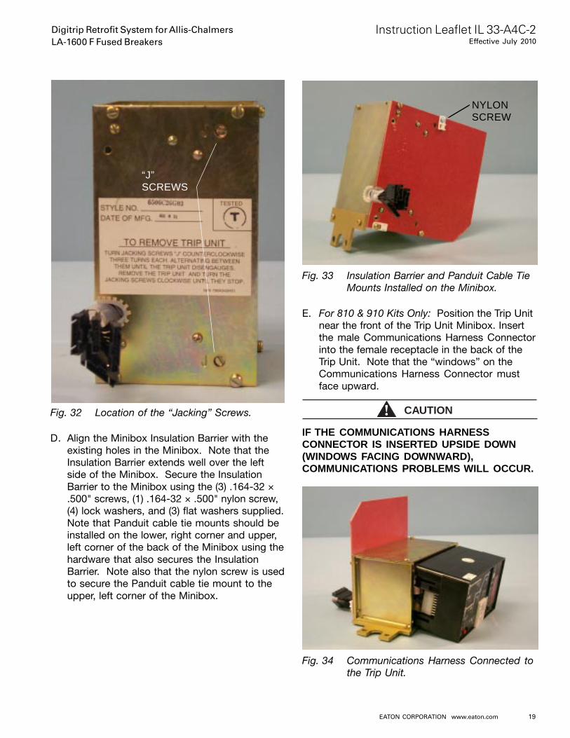
D. Align the Minibox Insulation Barrier with theexisting holes in the Minibox. Note that theInsulation Barrier extends well over the leftside of the Minibox. Secure the InsulationBarrier to the Minibox using the (3) .164-32 ×.500" screws, (1) .164-32 × .500" nylon screw,(4) lock washers, and (3) flat washers supplied.Note that Panduit cable tie mounts should beinstalled on the lower, right corner and upper,left corner of the back of the Minibox using thehardware that also secures the InsulationBarrier. Note also that the nylon screw is usedto secure the Panduit cable tie mount to theupper, left corner of the Minibox.
NYLONSCREW
Fig. 33 Insulation Barrier and Panduit Cable TieMounts Installed on the Minibox.
E. For 810 & 910 Kits Only: Position the Trip Unitnear the front of the Trip Unit Minibox. Insertthe male Communications Harness Connectorinto the female receptacle in the back of theTrip Unit. Note that the “windows” on theCommunications Harness Connector mustface upward.
CAUTION
Fig. 34 Communications Harness Connected tothe Trip Unit.
“J”SCREWS
IF THE COMMUNICATIONS HARNESSCONNECTOR IS INSERTED UPSIDE DOWN(WINDOWS FACING DOWNWARD),COMMUNICATIONS PROBLEMS WILL OCCUR.
Digitrip Retrofit System for Allis-ChalmersLA-1600 F Fused Breakers
Instruction Leaflet IL 33-A4C-2Effective July 2010
20 EATON CORPORATION www.eaton.com
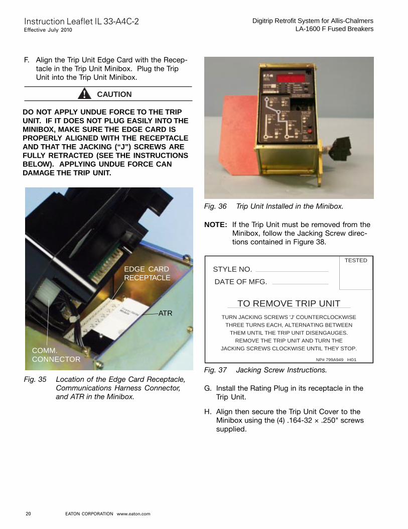
F. Align the Trip Unit Edge Card with the Recep-tacle in the Trip Unit Minibox. Plug the TripUnit into the Trip Unit Minibox.
CAUTION
DO NOT APPLY UNDUE FORCE TO THE TRIPUNIT. IF IT DOES NOT PLUG EASILY INTO THEMINIBOX, MAKE SURE THE EDGE CARD ISPROPERLY ALIGNED WITH THE RECEPTACLEAND THAT THE JACKING (“J”) SCREWS AREFULLY RETRACTED (SEE THE INSTRUCTIONSBELOW). APPLYING UNDUE FORCE CANDAMAGE THE TRIP UNIT.
Fig. 35 Location of the Edge Card Receptacle,Communications Harness Connector,and ATR in the Minibox.
Fig. 36 Trip Unit Installed in the Minibox.
NOTE: If the Trip Unit must be removed from theMinibox, follow the Jacking Screw direc-tions contained in Figure 38.
Fig. 37 Jacking Screw Instructions.
G. Install the Rating Plug in its receptacle in theTrip Unit.
H. Align then secure the Trip Unit Cover to theMinibox using the (4) .164-32 × .250" screwssupplied.
TESTED
NP# 799A949 H01
STYLE NO.
DATE OF MFG.
THREE TURNS EACH, ALTERNATING BETWEEN
THEM UNTIL THE TRIP UNIT DISENGAUGES.
REMOVE THE TRIP UNIT AND TURN THE
JACKING SCREWS CLOCKWISE UNTIL THEY STOP.
TURN JACKING SCREWS 'J' COUNTERCLOCKWISE
TO REMOVE TRIP UNIT
EDGE CARDRECEPTACLE
ATR
COMM.CONNECTOR
Instruction Leaflet IL 33-A4C-2Effective July 2010
Digitrip Retrofit System for Allis-ChalmersLA-1600 F Fused Breakers
EATON CORPORATION www.eaton.com 21
Fig. 38 Rating Plug and Trip Unit Cover In-stalled.
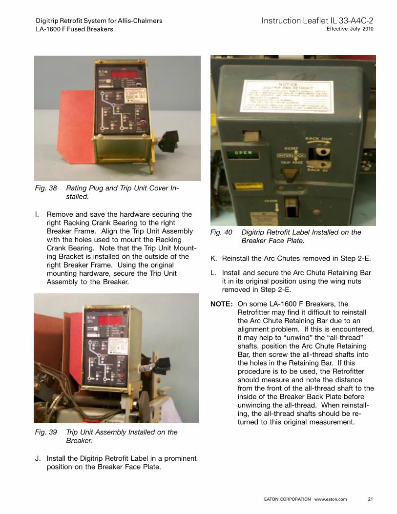
I. Remove and save the hardware securing theright Racking Crank Bearing to the rightBreaker Frame. Align the Trip Unit Assemblywith the holes used to mount the RackingCrank Bearing. Note that the Trip Unit Mount-ing Bracket is installed on the outside of theright Breaker Frame. Using the originalmounting hardware, secure the Trip UnitAssembly to the Breaker.
Fig. 39 Trip Unit Assembly Installed on theBreaker.
J. Install the Digitrip Retrofit Label in a prominentposition on the Breaker Face Plate.
Fig. 40 Digitrip Retrofit Label Installed on theBreaker Face Plate.
K. Reinstall the Arc Chutes removed in Step 2-E.
L. Install and secure the Arc Chute Retaining Barit in its original position using the wing nutsremoved in Step 2-E.
NOTE: On some LA-1600 F Breakers, theRetrofitter may find it difficult to reinstallthe Arc Chute Retaining Bar due to analignment problem. If this is encountered,it may help to “unwind” the “all-thread”shafts, position the Arc Chute RetainingBar, then screw the all-thread shafts intothe holes in the Retaining Bar. If thisprocedure is to be used, the Retrofittershould measure and note the distancefrom the front of the all-thread shaft to theinside of the Breaker Back Plate beforeunwinding the all-thread. When reinstall-ing, the all-thread shafts should be re-turned to this original measurement.
Digitrip Retrofit System for Allis-ChalmersLA-1600 F Fused Breakers
Instruction Leaflet IL 33-A4C-2Effective July 2010
22 EATON CORPORATION www.eaton.com
STEP 9: INSTALLING THE EXTERNALHARNESS
Fig. 41 Overview: External Harness Connectedto the Trip Unit.
A. Install the supplied Spiral Wrap on the bottomsection of the Aux. CT Harness. Plug the Aux.CT Harness into the connector on the Aux. CTModule Pigtail.
Fig. 42 Aux. CT Harness Connected to the Aux.CT Module Pigtail.
B. Route the Aux. CT Harness between the rightBreaker Frame and Phase 3 right PhaseBarrier, as shown, then upwards toward theTrip Unit. Connect the Aux. CT Harness to itsreceptacle at the rear of the Minibox. Use theself-adhesive mounting pads and wire tiessupplied to secure the Aux. CT Harness to thePhase 3 right Phase Barrier.
Fig. 43 Routing and Connection of the Aux. CTHarness to the Minibox.
C. Connect the External Harness to the recep-tacle in the pigtail at the rear of the Minibox.Temporarily route the External Harness to-wards the right side of the Breaker.
Fig. 44 External Harness Connected to theMinibox.
NOTE: For 510 Basic Kits, the External Harnessis the Shorting Plug pictured below. It isto be plugged into the correspondingreceptacle in the Minibox Pigtail.
Instruction Leaflet IL 33-A4C-2Effective July 2010
Digitrip Retrofit System for Allis-ChalmersLA-1600 F Fused Breakers
EATON CORPORATION www.eaton.com 23
Fig. 45 510 Basic Kit External Harness ShortingPlug.
D. Plug the PT Extension Harness into the con-nector on the PT Harness.
Fig. 46 PT Extension Harness Connected to thePT Module Harness.
E. Route the PT Extension Harness between theright Breaker Frame and Phase 3 right PhaseBarrier, as shown, then upwards toward theTrip Unit. Connect the PT Extension to thecorresponding plug on the External Harness.Use the self-adhesive mounting pads (in-stalled in Step 9-B) and wire ties supplied tosecure the PT Extension Harness to the Phase3 right Phase Barrier.
Fig. 47 Routing and Connection of the PTExtension Harness to the External Har-ness.
F. Route the two (2) wires, with ring terminals,from the External Harness, behind theMinibox, then down along the front of theBreaker to the Aux. Switch. Connect one(1) wire to the normally “Open” terminal andthe other wire to the “Common” terminal.Secure the Aux. Switch Wires to the front DTAAssembly Mounting Bracket using the wireties supplied.

Digitrip Retrofit System for Allis-ChalmersLA-1600 F Fused Breakers
Instruction Leaflet IL 33-A4C-2Effective July 2010
24 EATON CORPORATION www.eaton.com
Fig. 48 Routing and Connection of the AuxiliarySwitch Wires to the Auxiliary Switch.
G. Use the wire tie supplied to secure the Exter-nal Harness to the Panduit cable tie mountinstalled on the back of the Minibox.
Fig. 49 External Harness Secured to theMinibox.
Instruction Leaflet IL 33-A4C-2Effective July 2010
Digitrip Retrofit System for Allis-ChalmersLA-1600 F Fused Breakers
EATON CORPORATION www.eaton.com 25
For Kits Supplied with a Breaker Mounted CPTOnly.
STEP 10: INSTALLING THE BREAKERMOUNTED CPT MODULE
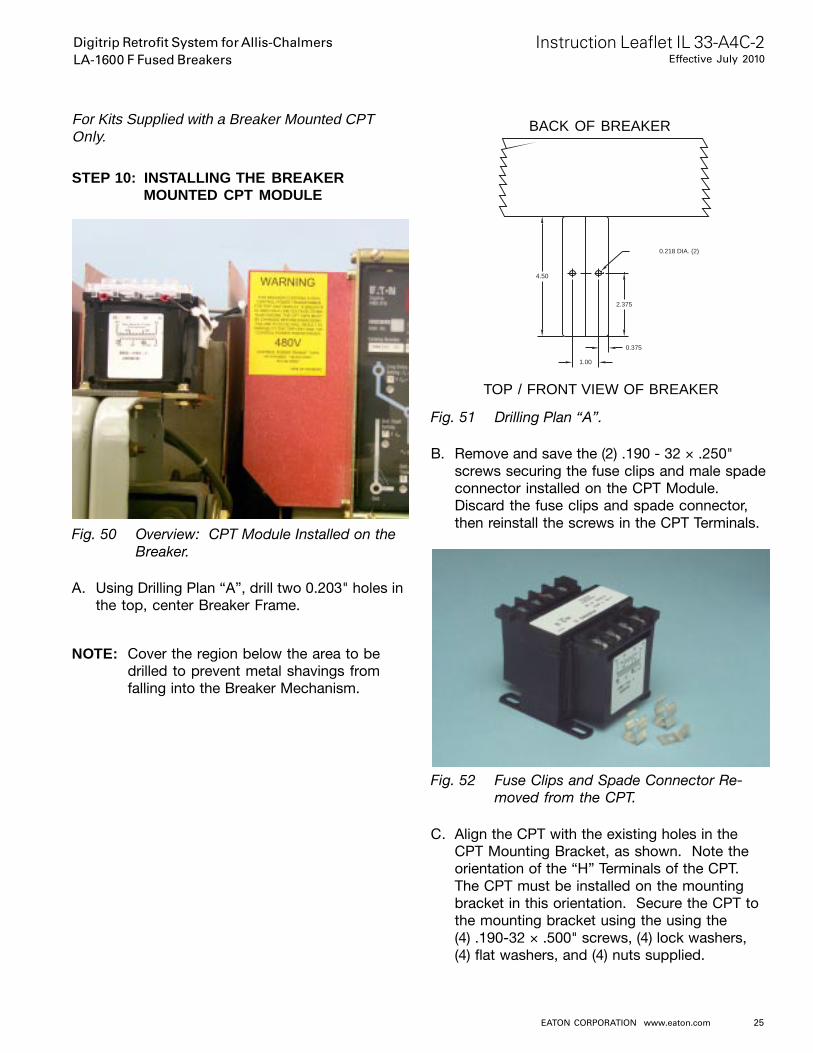
Fig. 51 Drilling Plan “A”.
B. Remove and save the (2) .190 - 32 × .250"screws securing the fuse clips and male spadeconnector installed on the CPT Module.Discard the fuse clips and spade connector,then reinstall the screws in the CPT Terminals.
Fig. 50 Overview: CPT Module Installed on theBreaker.
A. Using Drilling Plan “A”, drill two 0.203" holes inthe top, center Breaker Frame.
NOTE: Cover the region below the area to bedrilled to prevent metal shavings fromfalling into the Breaker Mechanism.
Fig. 52 Fuse Clips and Spade Connector Re-moved from the CPT.
C. Align the CPT with the existing holes in theCPT Mounting Bracket, as shown. Note theorientation of the “H” Terminals of the CPT.The CPT must be installed on the mountingbracket in this orientation. Secure the CPT tothe mounting bracket using the using the(4) .190-32 × .500" screws, (4) lock washers,(4) flat washers, and (4) nuts supplied.
2.375
0.375
1.00
4.50
0.218 DIA. (2)
BACK OF BREAKER
TOP / FRONT VIEW OF BREAKER
Digitrip Retrofit System for Allis-ChalmersLA-1600 F Fused Breakers
Instruction Leaflet IL 33-A4C-2Effective July 2010
26 EATON CORPORATION www.eaton.com
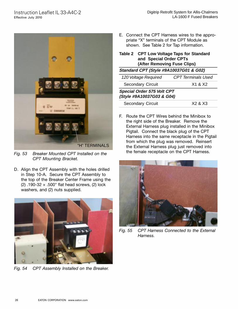
E. Connect the CPT Harness wires to the appro-priate “X” terminals of the CPT Module asshown. See Table 2 for Tap information.
Table 2 CPT Low Voltage Taps for Standardand Special Order CPTs(After Removing Fuse Clips)
Standard CPT (Style #9A10037G01 & G02)
120 Voltage Required CPT Terminals Used
Secondary Circuit X1 & X2
Special Order 575 Volt CPT(Style #9A10037G03 & G04)
Secondary Circuit X2 & X3
F. Route the CPT Wires behind the Minibox tothe right side of the Breaker. Remove theExternal Harness plug installed in the MiniboxPigtail. Connect the black plug of the CPTHarness into the same receptacle in the Pigtailfrom which the plug was removed. Reinsertthe External Harness plug just removed intothe female receptacle on the CPT Harness.Fig. 53 Breaker Mounted CPT Installed on the
CPT Mounting Bracket.
D. Align the CPT Assembly with the holes drilledin Step 10-A. Secure the CPT Assembly tothe top of the Breaker Center Frame using the(2) .190-32 × .500" flat head screws, (2) lockwashers, and (2) nuts supplied.
“H” TERMINALS
Fig. 54 CPT Assembly Installed on the Breaker.
Fig. 55 CPT Harness Connected to the ExternalHarness.
Instruction Leaflet IL 33-A4C-2Effective July 2010
Digitrip Retrofit System for Allis-ChalmersLA-1600 F Fused Breakers
EATON CORPORATION www.eaton.com 27
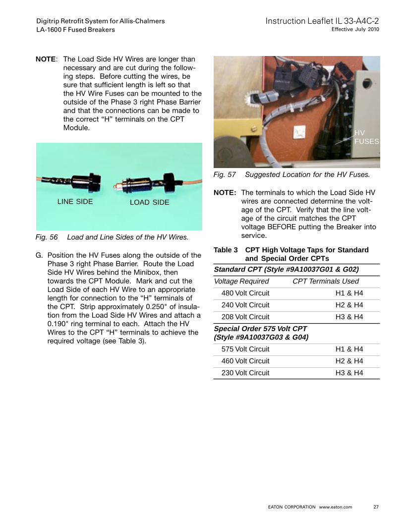
NOTE: The Load Side HV Wires are longer thannecessary and are cut during the follow-ing steps. Before cutting the wires, besure that sufficient length is left so thatthe HV Wire Fuses can be mounted to theoutside of the Phase 3 right Phase Barrierand that the connections can be made tothe correct “H” terminals on the CPTModule.
LINE SIDE LOAD SIDE
Fig. 56 Load and Line Sides of the HV Wires.
G. Position the HV Fuses along the outside of thePhase 3 right Phase Barrier. Route the LoadSide HV Wires behind the Minibox, thentowards the CPT Module. Mark and cut theLoad Side of each HV Wire to an appropriatelength for connection to the “H” terminals ofthe CPT. Strip approximately 0.250" of insula-tion from the Load Side HV Wires and attach a0.190" ring terminal to each. Attach the HVWires to the CPT “H” terminals to achieve therequired voltage (see Table 3).
Fig. 57 Suggested Location for the HV Fuses.
NOTE: The terminals to which the Load Side HVwires are connected determine the volt-age of the CPT. Verify that the line volt-age of the circuit matches the CPTvoltage BEFORE putting the Breaker intoservice.
Table 3 CPT High Voltage Taps for Standardand Special Order CPTs
Standard CPT (Style #9A10037G01 & G02)
Voltage Required CPT Terminals Used
480 Volt Circuit H1 & H4
240 Volt Circuit H2 & H4
208 Volt Circuit H3 & H4
Special Order 575 Volt CPT(Style #9A10037G03 & G04)
575 Volt Circuit H1 & H4
460 Volt Circuit H2 & H4
230 Volt Circuit H3 & H4
HVFUSES
Digitrip Retrofit System for Allis-ChalmersLA-1600 F Fused Breakers
Instruction Leaflet IL 33-A4C-2Effective July 2010
28 EATON CORPORATION www.eaton.com
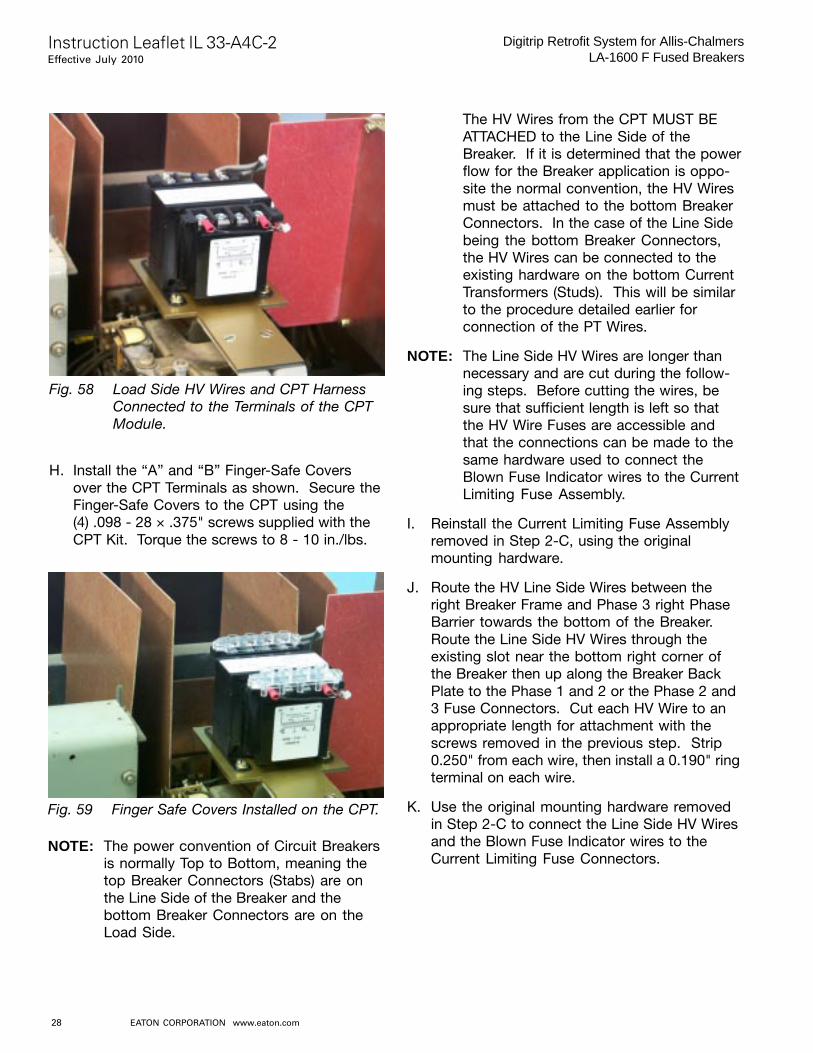
Fig. 58 Load Side HV Wires and CPT HarnessConnected to the Terminals of the CPTModule.
H. Install the “A” and “B” Finger-Safe Coversover the CPT Terminals as shown. Secure theFinger-Safe Covers to the CPT using the(4) .098 - 28 × .375" screws supplied with theCPT Kit. Torque the screws to 8 - 10 in./lbs.
The HV Wires from the CPT MUST BEATTACHED to the Line Side of theBreaker. If it is determined that the powerflow for the Breaker application is oppo-site the normal convention, the HV Wiresmust be attached to the bottom BreakerConnectors. In the case of the Line Sidebeing the bottom Breaker Connectors,the HV Wires can be connected to theexisting hardware on the bottom CurrentTransformers (Studs). This will be similarto the procedure detailed earlier forconnection of the PT Wires.
NOTE: The Line Side HV Wires are longer thannecessary and are cut during the follow-ing steps. Before cutting the wires, besure that sufficient length is left so thatthe HV Wire Fuses are accessible andthat the connections can be made to thesame hardware used to connect theBlown Fuse Indicator wires to the CurrentLimiting Fuse Assembly.
I. Reinstall the Current Limiting Fuse Assemblyremoved in Step 2-C, using the originalmounting hardware.
J. Route the HV Line Side Wires between theright Breaker Frame and Phase 3 right PhaseBarrier towards the bottom of the Breaker.Route the Line Side HV Wires through theexisting slot near the bottom right corner ofthe Breaker then up along the Breaker BackPlate to the Phase 1 and 2 or the Phase 2 and3 Fuse Connectors. Cut each HV Wire to anappropriate length for attachment with thescrews removed in the previous step. Strip0.250" from each wire, then install a 0.190" ringterminal on each wire.
K. Use the original mounting hardware removedin Step 2-C to connect the Line Side HV Wiresand the Blown Fuse Indicator wires to theCurrent Limiting Fuse Connectors.
Fig. 59 Finger Safe Covers Installed on the CPT.
NOTE: The power convention of Circuit Breakersis normally Top to Bottom, meaning thetop Breaker Connectors (Stabs) are onthe Line Side of the Breaker and thebottom Breaker Connectors are on theLoad Side.
Instruction Leaflet IL 33-A4C-2Effective July 2010
Digitrip Retrofit System for Allis-ChalmersLA-1600 F Fused Breakers
EATON CORPORATION www.eaton.com 29
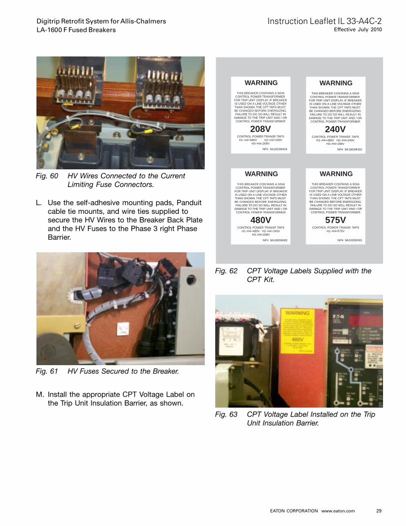
Fig. 60 HV Wires Connected to the CurrentLimiting Fuse Connectors.
L. Use the self-adhesive mounting pads, Panduitcable tie mounts, and wire ties supplied tosecure the HV Wires to the Breaker Back Plateand the HV Fuses to the Phase 3 right PhaseBarrier.
Fig. 61 HV Fuses Secured to the Breaker.
M. Install the appropriate CPT Voltage Label onthe Trip Unit Insulation Barrier, as shown.
208VCONTROL POWER TRANSF. TAPS
H1–H4=480V H2–H4=240VH3–H4=208V
WARNINGTHIS BREAKER CONTAINS A 50VA
CONTROL POWER TRANSFORMER FOR TRIP UNIT DISPLAY. IF BREAKERIS USED ON A LINE VOLTAGE OTHERTHAN SHOWN. THE CPT TAPS MUST BE CHANGED BEFORE ENERGIZING.FAILURE TO DO SO WILL RESULT IN
DAMAGE TO THE TRIP UNIT AND / ORCONTROL POWER TRANSFORMER
NP# 9A10039H04
240VCONTROL POWER TRANSF. TAPS
H1–H4=480V H2–H4=240VH3–H4=208V
WARNINGTHIS BREAKER CONTAINS A 50VA
CONTROL POWER TRANSFORMER FOR TRIP UNIT DISPLAY. IF BREAKERIS USED ON A LINE VOLTAGE OTHERTHAN SHOWN. THE CPT TAPS MUST BE CHANGED BEFORE ENERGIZING.FAILURE TO DO SO WILL RESULT IN
DAMAGE TO THE TRIP UNIT AND / ORCONTROL POWER TRANSFORMER
NP# 9A10039H03
480VCONTROL POWER TRANSF. TAPS
H1–H4=480V H2–H4=240VH3–H4=208V
WARNINGTHIS BREAKER CONTAINS A 50VA
CONTROL POWER TRANSFORMER FOR TRIP UNIT DISPLAY. IF BREAKERIS USED ON A LINE VOLTAGE OTHERTHAN SHOWN. THE CPT TAPS MUST BE CHANGED BEFORE ENERGIZING.FAILURE TO DO SO WILL RESULT IN
DAMAGE TO THE TRIP UNIT AND / ORCONTROL POWER TRANSFORMER
NP# 9A10039H02
575VCONTROL POWER TRANSF. TAPS
H1–H4=575V
WARNINGTHIS BREAKER CONTAINS A 50VA
CONTROL POWER TRANSFORMER FOR TRIP UNIT DISPLAY. IF BREAKERIS USED ON A LINE VOLTAGE OTHERTHAN SHOWN. THE CPT TAPS MUST BE CHANGED BEFORE ENERGIZING.FAILURE TO DO SO WILL RESULT IN
DAMAGE TO THE TRIP UNIT AND / ORCONTROL POWER TRANSFORMER
NP# 9A10039H01
Fig. 62 CPT Voltage Labels Supplied with theCPT Kit.
Fig. 63 CPT Voltage Label Installed on the TripUnit Insulation Barrier.
Digitrip Retrofit System for Allis-ChalmersLA-1600 F Fused Breakers
Instruction Leaflet IL 33-A4C-2Effective July 2010
30 EATON CORPORATION www.eaton.com
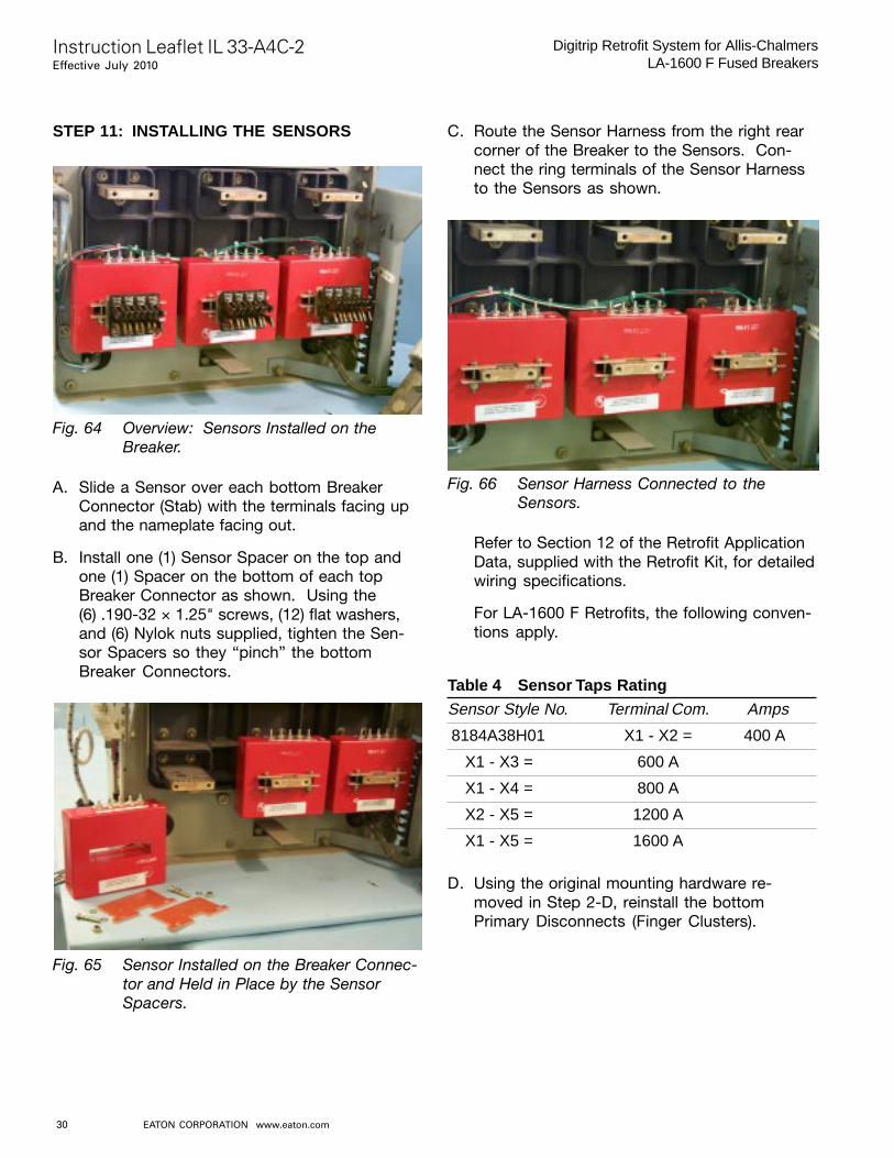
STEP 11: INSTALLING THE SENSORS C. Route the Sensor Harness from the right rearcorner of the Breaker to the Sensors. Con-nect the ring terminals of the Sensor Harnessto the Sensors as shown.
Fig. 64 Overview: Sensors Installed on theBreaker.
A. Slide a Sensor over each bottom BreakerConnector (Stab) with the terminals facing upand the nameplate facing out.
B. Install one (1) Sensor Spacer on the top andone (1) Spacer on the bottom of each topBreaker Connector as shown. Using the(6) .190-32 × 1.25" screws, (12) flat washers,and (6) Nylok nuts supplied, tighten the Sen-sor Spacers so they “pinch” the bottomBreaker Connectors.
Fig. 65 Sensor Installed on the Breaker Connec-tor and Held in Place by the SensorSpacers.
Fig. 66 Sensor Harness Connected to theSensors.
Refer to Section 12 of the Retrofit ApplicationData, supplied with the Retrofit Kit, for detailedwiring specifications.
For LA-1600 F Retrofits, the following conven-tions apply.
Table 4 Sensor Taps RatingSensor Style No. Terminal Com. Amps
8184A38H01 X1 - X2 = 400 A
X1 - X3 = 600 A
X1 - X4 = 800 A
X2 - X5 = 1200 A
X1 - X5 = 1600 A
D. Using the original mounting hardware re-moved in Step 2-D, reinstall the bottomPrimary Disconnects (Finger Clusters).
Instruction Leaflet IL 33-A4C-2Effective July 2010
Digitrip Retrofit System for Allis-ChalmersLA-1600 F Fused Breakers
EATON CORPORATION www.eaton.com 31
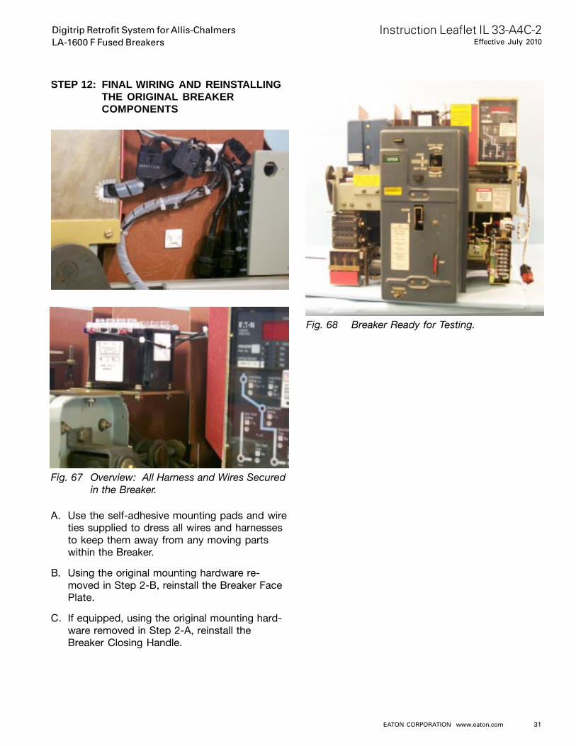
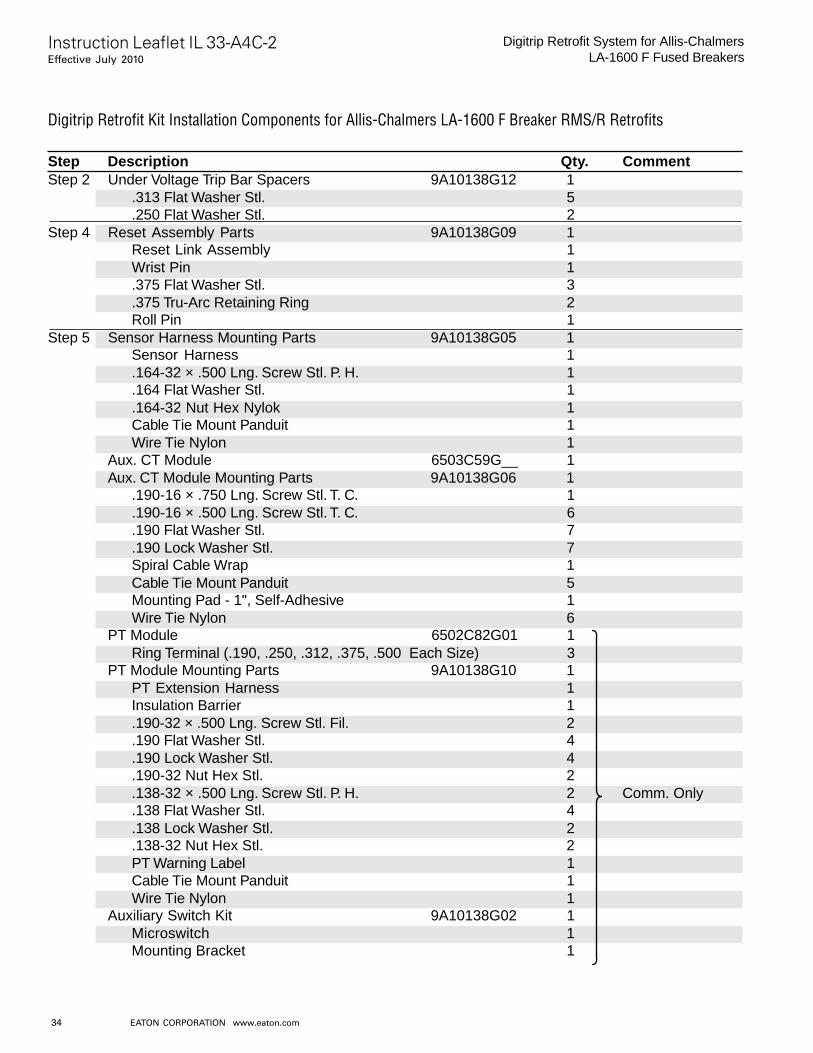
STEP 12: FINAL WIRING AND REINSTALLINGTHE ORIGINAL BREAKERCOMPONENTS
Fig. 68 Breaker Ready for Testing.
Fig. 67 Overview: All Harness and Wires Securedin the Breaker.
A. Use the self-adhesive mounting pads and wireties supplied to dress all wires and harnessesto keep them away from any moving partswithin the Breaker.
B. Using the original mounting hardware re-moved in Step 2-B, reinstall the Breaker FacePlate.
C. If equipped, using the original mounting hard-ware removed in Step 2-A, reinstall theBreaker Closing Handle.

Digitrip Retrofit System for Allis-ChalmersLA-1600 F Fused Breakers
Instruction Leaflet IL 33-A4C-2Effective July 2010
32 EATON CORPORATION www.eaton.com
STEP 13: TESTING THE BREAKER
A. Measure the force necessary to trip theBreaker at where the Trip Finger impacts theDTA Adjusting Disk. The force necessary totrip the Breaker MUST NOT EXCEED 3 lbs.
B. The Retrofit must be tested using primaryinjection. Refer to Section 8 of the Instructionsfor the Application of Digitrip RMS Retrofit Kitson Power Circuit Breakers (Publication AD 33-855), supplied with the Retrofit Kit, for detailedtesting procedures and specifications. Fortest information specific to the Trip Unit, referto the IL publication supplied with the RetrofitKit (see the Pick List for the IL number).
C. While Section 8 of the Instructions for theApplication of Digitrip RMS Retrofit Kits onPower Circuit Breakers provides the informa-tion necessary for testing the Breaker, pleasekeep the following notes in mind when review-ing other sections of the publication.
Confirm that the PowerNet communicationwiring is correct by following the proce-dures detailed in Section 7.4 of the Instruc-tions for the Application of Digitrip RMSRetrofit Kits on Power Circuit Breakers.Note that for 810 and 910 Kits, the imped-ance between COM 1 and COM 2 should bebetween one (1) and three (3) ohms.
When testing is complete, disconnect theExternal Harness from the Cell Harness.Final External Harness connection will beperformed later in the Retrofit Process.
CAUTION
WHEN ALL TESTING IS COMPLETE, THE TRIPUNIT MUST BE RESET. FAILURE TO DO SOMAY CAUSE THE BATTERY IN THE RATINGPLUG TO RUN DOWN.
NOTES:
1. For All Kits Other Than 510 Basic: If testingthe Breaker with Short Delay or GroundFault functions, be sure to either plug in theCell Harness Assembly or use the ZoneInterlock Shorting Plug. Failure to do somay result in shorter than expected triptimes.
2. For 810 and 910 Kits Only: Without anypower applied to the system (neither the 120volt power supply nor the Aux. Power Mod-ule connected), plug the External Harnessinto the Cell Harness and check the imped-ance between COM 1 and COM 2. Theimpedance should be between one (1) andthree (3) ohms. If the impedance is notwithin this range, trace the wiring andexamine each connection to assure itsintegrity.

Instruction Leaflet IL 33-A4C-2Effective July 2010
Digitrip Retrofit System for Allis-ChalmersLA-1600 F Fused Breakers
EATON CORPORATION www.eaton.com 33
STEP 14: MOUNTING THE CELL HARNESS
A. The Cell Harness is to be mounted in theBreaker Cell. The connector end is to bemounted on the right side of the Cell, in alocation suitable for connection with theExternal Harness. The Terminal Blocks can bemounted anywhere space is available in theCell as long as connection to the ExternalHarness can be made.
B. Route the Cell Harness wiring to keep it awayfrom any moving parts within the Cell Housing.
STEP 15: INSTALLING THE RETROFITTEDBREAKER IN THE CELL
WARNING
DO NOT LEAVE THE BREAKER IN AN INTER-MEDIATE POSITION IN THE SWITCHGEARCELL. ALWAYS LEAVE IT IN THE CONNECTED,DISCONNECTED, OR (OPTIONAL) TEST POSI-TION. FAILURE TO DO SO COULD LEAD TOIMPROPER POSITIONING OF THE BREAKERAND FLASHOVER, CAUSING DEATH, SERIOUSPERSONAL INJURY, AND / OR PROPERTYDAMAGE.
NOTE: It is the responsibility of the Retrofitterto insure proper Breaker / Cell fit. Whenracking the Breaker into the Connectedposition, the Retrofitter MUST FOLLOWBOTH the manufacturer’s instructionsand the customer’s safety standardsand procedures for racking a Breakerinto the Connected position.
A. With the Breaker in the Open position and thesprings discharged, slowly rack the Breakerinto the Connected position, making surethere is no interference or binding. TheBreaker should rack smoothly and withoutmechanical interference between any Breakerand Cell parts. The Retrofitter will feel someresistance when the primary fingers connectonto the stabs of the Cell. This is normal.
However, if any unusual resistance is detectedthat could be abnormal interference betweenthe Breaker and Cell parts, stop immediatelyand move the Breaker out of the Connectedposition. Examine what is causing the interfer-ence and correct the situation.
Digitrip Retrofit System for Allis-ChalmersLA-1600 F Fused Breakers
Instruction Leaflet IL 33-A4C-2Effective July 2010
34 EATON CORPORATION www.eaton.com
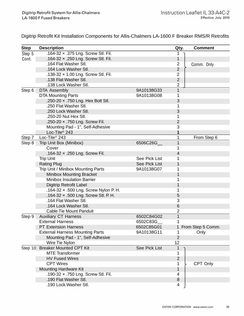
Digitrip Retrofit Kit Installation Components for Allis-Chalmers LA-1600 F Breaker RMS/R Retrofits
Step Description Qty. CommentStep 2 Under Voltage Trip Bar Spacers 9A10138G12 1
.313 Flat Washer Stl. 5
.250 Flat Washer Stl. 2Step 4 Reset Assembly Parts 9A10138G09 1
Reset Link Assembly 1Wrist Pin 1.375 Flat Washer Stl. 3.375 Tru-Arc Retaining Ring 2Roll Pin 1
Step 5 Sensor Harness Mounting Parts 9A10138G05 1Sensor Harness 1.164-32 × .500 Lng. Screw Stl. P. H. 1.164 Flat Washer Stl. 1.164-32 Nut Hex Nylok 1Cable Tie Mount Panduit 1Wire Tie Nylon 1
Aux. CT Module 6503C59G__ 1Aux. CT Module Mounting Parts 9A10138G06 1
.190-16 × .750 Lng. Screw Stl. T. C. 1
.190-16 × .500 Lng. Screw Stl. T. C. 6
.190 Flat Washer Stl. 7
.190 Lock Washer Stl. 7Spiral Cable Wrap 1Cable Tie Mount Panduit 5Mounting Pad - 1", Self-Adhesive 1Wire Tie Nylon 6
PT Module 6502C82G01 1Ring Terminal (.190, .250, .312, .375, .500 Each Size) 3
PT Module Mounting Parts 9A10138G10 1PT Extension Harness 1Insulation Barrier 1.190-32 × .500 Lng. Screw Stl. Fil. 2.190 Flat Washer Stl. 4.190 Lock Washer Stl. 4.190-32 Nut Hex Stl. 2.138-32 × .500 Lng. Screw Stl. P. H. 2 Comm. Only.138 Flat Washer Stl. 4.138 Lock Washer Stl. 2.138-32 Nut Hex Stl. 2PT Warning Label 1Cable Tie Mount Panduit 1Wire Tie Nylon 1
Auxiliary Switch Kit 9A10138G02 1Microswitch 1Mounting Bracket 1
Instruction Leaflet IL 33-A4C-2Effective July 2010
Digitrip Retrofit System for Allis-ChalmersLA-1600 F Fused Breakers
EATON CORPORATION www.eaton.com 35
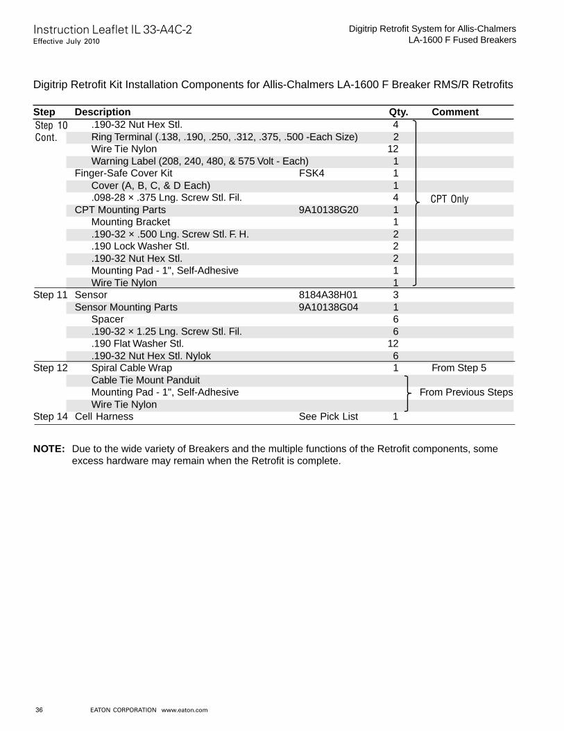
Digitrip Retrofit Kit Installation Components for Allis-Chalmers LA-1600 F Breaker RMS/R Retrofits
Step Description Qty. Comment.164-32 × .375 Lng. Screw Stl. Fil. 1.164-32 × .250 Lng. Screw Stl. Fil. 1.164 Flat Washer Stl. 2.164 Lock Washer Stl. 2.138-32 × 1.00 Lng. Screw Stl. Fil. 2.138 Flat Washer Stl. 2.138 Lock Washer Stl. 2
Step 6 DTA Assembly 9A10138G33 1DTA Mounting Parts 9A10138G08 1
.250-20 × .750 Lng. Hex Bolt Stl. 3
.250 Flat Washer Stl. 1
.250 Lock Washer Stl. 3
.250-20 Nut Hex Stl. 1
.250-20 × .750 Lng. Screw Fil. 2Mounting Pad - 1", Self-Adhesive 3Loc-Tite® 243 1
Step 7 Loc-Tite® 243 1 From Step 6Step 8 Trip Unit Box (Minibox) 6506C26G__ 1
Cover 1.164-32 × .250 Lng. Screw Fil. 4
Trip Unit See Pick List 1Rating Plug See Pick List 1Trip Unit / Minibox Mounting Parts 9A10138G07 1
Minibox Mounting Bracket 1Minibox Insulation Barrier 1Digitrip Retrofit Label 1.164-32 × .500 Lng. Screw Nylon P. H. 1.164-32 × .500 Lng. Screw Stl. P. H. 5.164 Flat Washer Stl. 3.164 Lock Washer Stl. 6Cable Tie Mount Panduit 2
Step 9 Auxiliary CT Harness 6502C84G02 1External Harness 6502C83G__ 1PT Extension Harness 6502C85G01 1 From Step 5 Comm.External Harness Mounting Parts 9A10138G11 1 Only
Mounting Pad - 1", Self-Adhesive 2Wire Tie Nylon 12
Step 10 Breaker Mounted CPT Kit See Pick List 1MTE Transformer 1HV Fused Wires 2CPT Wires 1 CPT Only
Mounting Hardware Kit 1.190-32 × .750 Lng. Screw Stl. Fil. 4.190 Flat Washer Stl. 8.190 Lock Washer Stl. 4
Step 5Cont.
Comm. Only
Digitrip Retrofit System for Allis-ChalmersLA-1600 F Fused Breakers
Instruction Leaflet IL 33-A4C-2Effective July 2010
36 EATON CORPORATION www.eaton.com
Digitrip Retrofit Kit Installation Components for Allis-Chalmers LA-1600 F Breaker RMS/R Retrofits
Step Description Qty. Comment.190-32 Nut Hex Stl. 4Ring Terminal (.138, .190, .250, .312, .375, .500 -Each Size) 2Wire Tie Nylon 12Warning Label (208, 240, 480, & 575 Volt - Each) 1
Finger-Safe Cover Kit FSK4 1Cover (A, B, C, & D Each) 1.098-28 × .375 Lng. Screw Stl. Fil. 4
CPT Mounting Parts 9A10138G20 1Mounting Bracket 1.190-32 × .500 Lng. Screw Stl. F. H. 2.190 Lock Washer Stl. 2.190-32 Nut Hex Stl. 2Mounting Pad - 1", Self-Adhesive 1Wire Tie Nylon 1
Step 11 Sensor 8184A38H01 3Sensor Mounting Parts 9A10138G04 1
Spacer 6.190-32 × 1.25 Lng. Screw Stl. Fil. 6.190 Flat Washer Stl. 12.190-32 Nut Hex Stl. Nylok 6
Step 12 Spiral Cable Wrap 1 From Step 5Cable Tie Mount PanduitMounting Pad - 1", Self-Adhesive From Previous StepsWire Tie Nylon
Step 14 Cell Harness See Pick List 1
NOTE: Due to the wide variety of Breakers and the multiple functions of the Retrofit components, someexcess hardware may remain when the Retrofit is complete.
Step 10Cont.
CPT Only

37
Instruction Leaflet IL 33-A4C-2Effective July 2010
Digitrip Retrofit System for Allis-Chalmers LA-1600 F Fused Breakers
EAton CoRpoRAtIon www.eaton.com
Table 5. Torque Values for General Mounting and Screw Size Conversion
Decimal Size (in) Standard Size Torque (in-lbs) Torque (ft-lbs)
.112 4.40 10 0.8
.138 6.32 18 1.5
.164 8.32 36 3.0
.190 10.32 46 3.8
.250 1/4-20 100 8.3
.312 5/16-18 206 17.2
.375 3/8-16 356 29.7
.438 7/16-14 572 47.7
.500 1/2-13 856 71.3
Table 6. Torque Values for Copper BUS Connectors
Decimal Size (in) Standard Size Torque (in-lbs) Torque (ft-lbs)
.250 1/4-20 60 5
.312 5/16-18 144 12
.375 3/8-16 240 20
.500 1/2-13 600 50

Digitrip Retrofit System for Allis-ChalmersLA-1600 F Fused Breakers
Instruction Leaflet IL 33-A4C-2Effective July 2010
38 EATON CORPORATION www.eaton.com
Fig. 69 Retrofit Components
A. SensorsB. Trip UnitC. Aux. CT ModuleD. Direct Trip Actuator (DTA)E. CPT TransformerF. Rating PlugG. HV WiresH. Aux. CT Harness
I. Sensor HarnessJ. External HarnessK. Cell Terminal BlockL. Aux. SwitchM. PT ModuleN. Reset Link
AB
C
D
EF
G
H
I
J
K
L
M
N

39
Instruction Leaflet IL 33-A4C-2Effective July 2010
Digitrip Retrofit System for Allis-Chalmers LA-1600 F Fused Breakers
EAton CoRpoRAtIon www.eaton.com
Notes:
Instruction Leaflet IL 33-A4C-2Effective July 2010
Digitrip Retrofit System for Allis-Chalmers LA-1600 F Fused Breakers
Eaton CorporationElectrical Group1000 Cherrington ParkwayMoon Township, PA 15108United States877-ETN-CARE (877-386-2273)Eaton.com
© 2010 Eaton CorporationAll Rights ReservedPrinted in USAPublication No. IB 33-A4C-2 / TBG000368Part No. IL33-A4CH02July 2010
PowerChain Management is a registered trademark of Eaton Corporation.
All other trademarks are property of their respective owners.
The instructions for installation, testing, maintenance, or repair herein are provided for the use of the product in general commercial applications and may not be appropriate for use in nuclear applica-tions. Additional instructions may be available upon specific request to replace, amend, or supplement these instructions to qualify them for use with the product in safety-related applications in a nuclear facility.
The information, recommendations, descriptions, and safety nota-tions in this document are based on Eaton’s experience and judg-ment with respect to Retrofitting of Power Breakers. This instruction-al literature is published solely for information purposes and should not be considered all-inclusive. If further information is required, you should consult an authorized Eaton sales representative.
The sale of the product shown in this literature is subject to the terms and conditions outlined in appropriate Eaton selling policies or other contractual agreement between the parties. This literature is not intended to and does not enlarge or add to any such contract. The sole source governing the rights and remedies of any purchaser of this equipment is the contract between the purchaser and Eaton.
NO WARRANTIES, EXPRESSED OR IMPLIED, INCLUDING WARRANTIES OF FITNESS FOR A PARTICULAR PURPOSE OR MERCHANTABILITY, OR WARRANTIES ARISING FROM COURSE OF DEALING OR USAGE OF TRADE, ARE MADE REGARDING THE INFORMATION, RECOMMENDATIONS, AND DESCRIPTIONS CONTAINED HEREIN. In no event will Eaton be responsible to the purchaser or user in contract, in tort (including negligence), strict liability or otherwise for any special, indirect, incidental or conse-quential damage or loss whatsoever, including but not limited to damage or loss of use of equipment, plant or power system, cost of capital, loss of power, additional expenses in the use of existing power facilities, or claims against the purchaser or user by its cus-tomers resulting from the use of the information, recommendations and description contained herein.