digital video surveillance and security || site surveys
TRANSCRIPT
231Digital Video Surveillance and Security. http://dx.doi.org/10.1016/B978-0-12-420042-5.00007-1Copyright © 2014 Anthony C. Caputo. Published by Elsevier Inc. All rights reserved.
7Site Surveys
There are many types of DVS site surveys for camera locations, network equipment, conduit pathways, raceways, and ducts, both above and below ground. The objective is to gather and then document findings and information to assist in determining whether the desired location is suitable for the necessary equipment and meets the design requirements.
Prior to determining which physical site surveys are required to properly design the solution, overall due diligence can assist with decisions made in the field. I can’t tell you how many times I was assigned to do a site survey of a facility but never received the full address. Does this location have any network connectivity? Is there a network topology drawing? How will you gain access to the facility, and does it require an escort? Is there a contact person and a workspace?
A physical security assessment gathers an enterprise view of the current physical security profile along with a gap analysis. Often customers don’t understand all that is required to successfully implement their goals and objectives. The assessment would include review-ing existing physical security and surveillance architectures, network topologies, and, if a diagram isn’t available, confirming the need to schedule a network site survey to docu-ment existing equipment, not what the IT guy thinks they have, or their existing network capacity and configuration. This would also include any wireless technologies and regula-tory requirements. Physical security vulnerabilities should be documented and expressed, but it is my experience that most organizations are blind to threats and vulnerabilities until they become victims of a denial-of-service attack, hijacking, or theft.
This series of assessments may include individual interviews with select stakeholders in addition to a general brainstorming meeting. Due diligence is completed when enough information has been gathered to schedule the required site surveys for validation. Each survey can include an officially designated surveyor from the system integrator, the con-struction contractor, and even the customer or management entity.
The site survey should validate assessment information, including:
• Area of coverage (exactly what is to be monitored) • Power availability (existing exterior and interior power conduit and pathways for high,
medium, and low voltage) • Data pathways (exterior above- and below-ground duct banks, raceways, etc.) • Existing internal network topology (with existing data pathways) • Existing network configuration, availability, and accessibility • Existing main distribution facility (MDF), interim distribution facility (IDF), and data
center space and accessibility
The area of coverage refers to the area where there is a need to monitor or archive activ-ity. This could be a 360-degree area, a single doorway, an outdoor terrace, or a parking lot

232 DIGITAL VIDEO SURVEILLANCE AND SECURITY
egress and ingress or duress/panic alarm station. Wherever the location, it is assumed that someone somewhere wants this location monitored or video archived to present a capable guardian as a deterrent for whatever activity takes place, or may take place, and for video forensics. Understanding the purpose of and the reason for the surveillance will assist you in choosing the best technology and location. For example, if the requirement is to moni-tor a parking lot for vandalism and theft, installing a camera that can be reached, either by climbing onto the roof of a vehicle or by ladder, only adds another potential target for an assailant. In this particular example, the higher or more out of reach the camera is, the safer it is from being rendered inoperative.
Other areas of coverage are unique by project and location but can typically include:
• Doorways • Corridors • Parking lots • Common areas • Public transportation • Vehicles • Sensitive locations • Potential terrorist targets
Monitoring doorways offers a video record of those who exit and enter the facility and could reveal whatever they have in their hands. Doorway points of interest may be some-thing as simple as monitoring the front door of a home to anonymously review visitors ringing the doorbell, monitoring loading docks, or recording vehicles (and license plates) moving in and out of a parking garage.
Adequately capturing the area of coverage for any doorway does not include mounting the camera anywhere above the door, since doing so will guarantee capturing any and all activity in and out of the doorway but will only give you a great shot of the top of everyone’s head. Typically, if you’re installing an outdoor camera, the ideal location for doorway cov-erage is face on, across the egress. This becomes difficult if the mounting location is on a neighbor’s property or a utility-owned pole. Yet unless you’re using covert cameras, mount-ing the camera on the inside of the doorway leaves it vulnerable to vandals. Installing the camera on the same wall of the doorway, at least 25 feet opposite the door hinges, will give a good line of sight. If double doors are used, set up the camera in the line of sight of the opened door, locking the other door in order to force individuals to exit facing one way.
Besides the obvious vandalism, drug trafficking, theft, and potential traps for other vio-lent crimes, corridors are also monitored for liability reasons.
Determining the area of coverage also requires understanding specifics of the cameras that are chosen for the solution. If the surveillance requires monitoring during both day and nighttime, a low-lux camera (see Chapter 3) would be required. If the area of coverage is pitch black at night, with limited or no visibility, infrared technology might be a good option.
One aspect of choosing surveillance solutions is to consider the angle of coverage pro-vided by each camera. If the parking lot is the required area of coverage to monitor traffic

Chapter 7 • Site Surveys 233
flow or potential theft and vandalism, a fixed camera with a wide-angle lens might be enough. However, if license plate recognition (LPR) and human or face recognition is also a requirement, a different camera is needed.
Video surveillance is most commonly used for scene overview—monitoring all activ-ity within a specific location. The depth of detail required in scene overview guides cam-era choice—for example, if the requirement calls for object identification beyond the make and model of an automobile or identification of whether a human figure is male or female. Unless you are planning on covering 20 specific locations with 20 cameras set at a 10-degree area of coverage (with a telephoto lens), pixel depth may be a more important consideration than the lens and angle or view.
Typically, when someone chooses a megapixel camera (see Chapter 3), they do so because there is a need for a larger area of coverage, reasoning that the camera provides more detail; therefore using a fisheye lens to monitor the entire area would satisfy the requirements. However, using a fisheye lens to cover as much of the area as possible doesn’t necessarily give you more pixel depth, just more general coverage, unless you choose a higher-megapixel camera. Human face recognition and LPR both require more pixel depth than the average surveillance camera.
License Plate RecognitionLPR, sometimes referred to as automated license plate recognition (ALPR), which cross-references the license plate number to national and/or international databases, captures a video image of a license plate and then uses an optical character recognition (OCR) algorithm to convert the plate number to the ASCII character set (see Chapter 3 for more details). For this to be a successful representation of the LPR, there must be a minimum of 25 pixels on the vertical side of the license plate characters. That would mean that a total of 5,000 pixels represent the entire license plate. Figure 7.1 shows the capture quality of LPR software.
The quality of the lens, the CCD or CMOS sensor, frame rate, and OCR software are all components for successful LPR, but the number of actual pixels is the core of the conver-sion from blurry image to factual ASCII representation of the license number. A successful camera installation for LPR requires a camera focused on a position where license plates are at least 5,000 pixels of the entire image.
Human RecognitionFacial recognition is much more complicated than LPR because the human face moves far more fluidly and may include various accessories such as sunglasses, hats, and scarves. If the video capture of a face were to be straight on into the camera lens, without any acces-sories, the bare minimum to identify a human face would be 25 to 75 pixels just between the eyes, which means that a total of about 10,000 to 20,000 pixels are needed to identify an entire face.

234 DIGITAL VIDEO SURVEILLANCE AND SECURITY
Determining the distance from the camera to the object of interest requires knowing both the horizontal distance from the camera and the camera’s height. There is a signifi-cant difference between the horizontal distance to an object of interest and its actual dis-tance once you have factored in the height of the camera. For example, if the goal is human facial recognition or identification, a camera on the side of a building may be 30 feet above a targeted egress. If a thief is 20 feet away from the egress, with the camera 30 feet above, the real distance is 36 feet, or 180% of the original horizontal distance.
Calculation of the true distance can be determined using the Pythagorean theorem. The Pythagorean theorem (A² + B² = C²) determines the length of one side of a triangle based on the lengths of the other two sides. Figure 7.2 depicts the distance to the face of the figure as 12 feet. The camera is placed 6 feet above the figure’s head. The exact distance is calculated as 6 squared plus 12 squared, which equals 180. To determine the distance to the subject’s face, you must find the square root of 180, which gives you an answer of about 13.5 feet.
The dimensions of the scene are then used to calculate the number of pixels represent-ing the figure’s face. A tool called a lens calculator can be used to determine the dimen-sions of the scene captured by a camera. If you Google lens calculator, a number will come up for you to use for free, or you can choose to use the IP Video System Design Tool, a small undiscovered gem available at www.jvsg.com (see Figure 7.3).
To use the lens calculator, you’ll need the focal length of the camera lens you’ll be using and the size of the CMOS or CCD sensor (see Chapter 3). Let’s assume a 1/3-inch sensor and a 9 millimeter (mm) lens. The lens calculator determines the scene dimensions to be about 6 feet by 8 feet (a standard 4 × 3 aspect ratio), making the scene 48 square feet (6 × 8 = 48) at 13.5 feet away. An estimation of a human face at that distance would be about 12 × 6 inches, taking up about half of a square foot, or .01 (1%) of the scene.
CIF
4CIF
2MP
5MP
FIGURE 7.1 LPR using CIF, 4 CIF, and MP. License plate recognition software is specifically designed to read license plates beyond the capability of the human eye.

Chapter 7 • Site Surveys 235
The number of pixels representing the face is calculated by determining the resolution used for monitoring (see Chapter 2). A single frame at CIF resolution (352 × 240) includes a total of 84,400 pixels. At 4 CIF resolution (704 × 480), there are 337,920 pixels, 1,310,720 pixels in a 1.3 megapixel (MP) camera (1280 × 1024), and a 3 MP camera includes 3,133,440 pixels per frame.
Figure 7.4 compares the number of facial pixels in three resolutions. The CIF image of the face would be represented by 775 pixels, whereas the 4 CIF image would be 8,680 pix-els. The face on a 3 MP camera embodies 42,525 pixels.
Table 7.1 shows the suggested percentage of pixels required for facial and license plate recognition; Figure 7.5 presents an example of facial images based on this table.
What I have used here is a simple example. However, in the outside world cameras are installed at least 25 feet high, away from unauthorized access and vandalism. With a cam-era that is placed 25 feet high, if someone walks by at about 15 feet, you’ll have a formula that looks more like 20² + 15² = ?², or 400 + 225 = 625. The distance between the camera and the subject’s face would then be 25 feet. Using the same 1/3-inch CMOS or CCD sensor and an 8 mm lens, the square footage would be 15 × 11, or 165, from 25 feet away. The size of the human head from 25 feet away would be about half of the previous example, making it about 6 inches × 3 inches, or about .05% of the overall area of coverage. At that size, with the same three previous resolutions (which would not change), you have about as many pixels for facial and/or license plate recognition. Table 7.2 summarizes the calculations used to determine number of facial pixels per resolution size.
12 feetB
6 feetA
SecurityCamera
HumanFace
13.5 feetC
A² + B² = C²
FIGURE 7.2 Using the Pythagorean theorem to find the real distance of the human figure.

236 DIGITAL VIDEO SURVEILLANCE AND SECURITY
FIGURE 7.3 The IP Video System Design Tool, available at www.jvsg.com, provides excellent functionality for storage and complex field-of-view calculations.
CIF775 Pixels
4CIF8,680 Pixels
3MP42,525 Pixels
FIGURE 7.4 Number of pixels for face recognition.

Chapter 7 • Site Surveys 237
Table 7.1 Recommended Pixels per Frame for Facial and License Plate Recognition
Object CIF 4 CIF 1 MP 3 MP
Pixels per frame 84,400 337,920 1,310,720 3,133,440
Facial pixels percentage (20,000) 24% .06% .015% .0063%
License plate pixels percentage (5,000) .06% .014% .0038% .0015%
4CIF 3MP
~200 GB (MPEG4 - Average Quality)~55 GB (H.264 - Average Quality)
~17 GB (MPEG4 - Average Quality)~8 GB (H.264 - Average Quality)
Daily Storage, 30fps Daily Storage, 30fps
FIGURE 7.5 Example of facial images based on Table 7.1.
Table 7.2 Number of Facial Pixels per Resolution Size
Camera ID
Height of Camera (A)
Horizontal Distance to Camera (B)
Pythagorean Theorem (A² + B² = C)
Actual Distance from Camera (C²)
Sensor Size
Lens Focal Length
Square Footage Covered (Lens Calculator)
Facial Size (%)
CIF Pixels
4 CIF Pixels
3 MP Pixels
1 6 ft. 12 ft. 6² + 12² = 180 13.5 ft. 1/3 in. 8 mm 48 .01 775 8.680 45,525

238 DIGITAL VIDEO SURVEILLANCE AND SECURITY
Power = Camera, No Power = No CameraThe initial site survey often serves merely as a preliminary introduction to the desired location, its target, and accessibility in the area. The site survey may only serve as a means for exploring the area, but remember that where there is no power, there is no camera, so determining power availability is always a good idea on the first exploratory site survey. As part of the site survey, be prepared to explain if there is no cost-effective method to deliver power to the required location. Keep in mind that power doesn’t necessarily need to come from the same location where the data is terminated, although having a separate circuit breaker for the cameras, with enough of a load to handle them, is always preferred. A single circuit breaker per camera is the optimal practice because if the camera requires main-tenance, you will need to shut down the power for only that individual camera and not a daisy-chained group (see Figure 7.6). Remember that if the cameras are down and there is a serious incident, there may be a legal liability for providing a false sense of security.
My work on many city-wide deployments required supplying power to various city light traffic poles and point-of-presence (POP) locations. Most city and public area lights are higher voltage and, more important, they’re either set on timers or use photo sen-sors to determine natural light, enabling them to automatically turn on or off at dawn and dusk. The power requirement for all security cameras (e.g., fixed, analog, CCTV, IP, etc.) is considered uninterrupted power or persistent power. That is, it is AC power that is
FIGURE 7.6 Check for space for dedicated circuit breakers for the cameras, and make sure to label them appropriately.

Chapter 7 • Site Surveys 239
available 24/7 and is typically a clean run of 110/120 volts. For most city-wide projects, every pole with a new camera required new individual wire installs from the source as well as a single dedicated circuit breaker. The size of the wire is based on the distance and voltage required, calculating for voltage load and voltage drops. There are a few use-ful voltage drop tools online that will calculate the gauge wire that is needed for the dis-tance required, and when you get into the #6 and #4 copper wire (about 3/8-inch thick) it becomes costly.
The pathway ran under the street, through manholes, and up the selected pole. Street pole locations typically are specifically designated at street intersections and will use power from the traffic controllers. The traffic control poles may already include 120 VAC but may need to be run from the traffic controller. There should also be a ground-ing mechanism within the pole that should be considered when installing new equip-ment. If the equipment is metal and is attached to the pole, confirm that the pole itself is grounded; otherwise, provide the grounding to protect the equipment from a lightning strike.
Usually, for municipalities, the traffic control poles are the most available assets for installing security equipment, because they are usually managed by the same city agen-cies that champion the surveillance system. The traffic controller also provides a power source and enclosure for installation of new equipment.
Park lighting poles are a different story. Recreational park poles may require additional persistent power installations, since the existing power may not only be daisy-chained back to the power source but could also include a timer that turns all power off during daylight hours.
The power options for recreational park poles without persistent power include using a step-down transformer from 240 VAC or 277 VAC to 120 VAC and removing the timer on daisy-chain circuits and adding photo cells onto each pole in the circuit while leaving the power live 24/7 to all park poles, with a bypass for persistent power at the select security equipment poles.
Replacing high-powered lamps with LED bulbs to reduce power consumption also provides the ability to leave power on 24/7 at camera poles for persistent power and to give additional security lighting for cameras. This would require adding photo cells only at noncamera park poles along the power circuit.
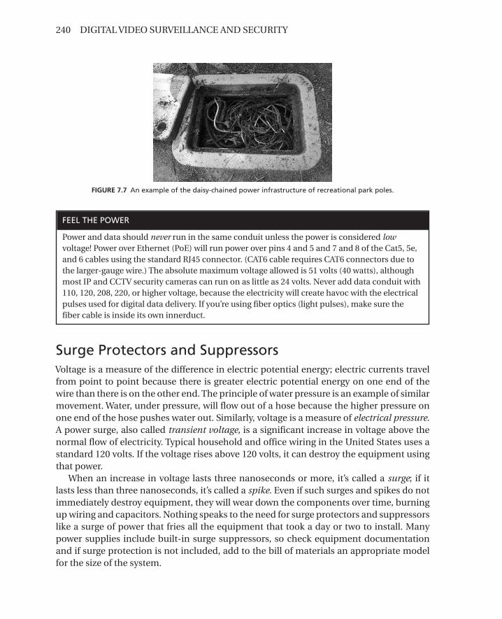
Running new wire (gauge depends on distance to power source) through existing conduit to provide a dedicated persistent power to camera and/or equipment poles may require rodding and/or blowing the existing conduit to clear a pathway for new wiring. This also assumes that conduit has sufficient fill ratio and isn’t crushed, cracked, broken, or packed with mud (see Figure 7.7). If existing wiring or conduit is determined to be unus-able, clearing the pathway can be costly.
In contrast, the island cottage case study from Chapter 1 required only a simple instal-lation of two fixed cameras, each requiring 24 VAC. A dedicated circuit was run from the power circuit breaker panel of 15A to power the adapters and transformers through a surge suppressor.
240 DIGITAL VIDEO SURVEILLANCE AND SECURITY
Surge Protectors and SuppressorsVoltage is a measure of the difference in electric potential energy; electric currents travel from point to point because there is greater electric potential energy on one end of the wire than there is on the other end. The principle of water pressure is an example of similar movement. Water, under pressure, will flow out of a hose because the higher pressure on one end of the hose pushes water out. Similarly, voltage is a measure of electrical pressure. A power surge, also called transient voltage, is a significant increase in voltage above the normal flow of electricity. Typical household and office wiring in the United States uses a standard 120 volts. If the voltage rises above 120 volts, it can destroy the equipment using that power.
When an increase in voltage lasts three nanoseconds or more, it’s called a surge; if it lasts less than three nanoseconds, it’s called a spike. Even if such surges and spikes do not immediately destroy equipment, they will wear down the components over time, burning up wiring and capacitors. Nothing speaks to the need for surge protectors and suppressors like a surge of power that fries all the equipment that took a day or two to install. Many power supplies include built-in surge suppressors, so check equipment documentation and if surge protection is not included, add to the bill of materials an appropriate model for the size of the system.
FIGURE 7.7 An example of the daisy-chained power infrastructure of recreational park poles.
FEEL THE POWER
Power and data should never run in the same conduit unless the power is considered low voltage! Power over Ethernet (PoE) will run power over pins 4 and 5 and 7 and 8 of the Cat5, 5e, and 6 cables using the standard RJ45 connector. (CAT6 cable requires CAT6 connectors due to the larger-gauge wire.) The absolute maximum voltage allowed is 51 volts (40 watts), although most IP and CCTV security cameras can run on as little as 24 volts. Never add data conduit with 110, 120, 208, 220, or higher voltage, because the electricity will create havoc with the electrical pulses used for digital data delivery. If you’re using fiber optics (light pulses), make sure the fiber cable is inside its own innerduct.

Chapter 7 • Site Surveys 241
Uninterrupted Power Supply (UPS)Uninterrupted power supply (UPS) continues to supply electric power to the required equipment for a select period of time when the traditional power supply is lost. Typically, the UPS is used for computers, to prevent them from a hard shutdown that could damage the operating system and mission-critical applications.
The UPS system standard IEC 62040-3 defines the amplitude and deviation of output volt-age acceptable for switching the AC power supply to the DC battery backup. Since the UPS does not require electricity from an outside source to function, it uses any number of energy-storing backup batteries, an AC-DC charger to keep the battery fully charged, and a DC-AC inverter to provide the necessary power to the required equipment. The primary UPS type used for electronic surveillance systems is the standby UPS, which will activate the battery backup when traditional AC input power fails. The typical power transfer time is between 2 and 10 milliseconds, depending on the amount of time it takes to detect the lost utility voltage and turn on the DC-AC inverter. During this time the power to the load is momentarily inter-rupted. The equipment’s power supply typically includes a ride-through or hold-up power, stored within its capacitors, that will hang on until the UPS kicks into action, thus preventing data loss. The typical ride-through power of a personal computer has at least 15 milliseconds.
Since the inverter must operate in a standby mode, operating only when input power fails, these UPS have the highest efficiency (95–97%) and reliability ratings. Although it is the least expensive type of UPS, the standby UPS typically includes software that auto-matically creates a soft shutdown of your operating system and turns off your computer.
A line interactive UPS regulates the input AC voltage using a filter and transformer. This is a bidirectional inverter/charger that is always connected to the output of the UPS to keep the battery charged. When the input power fails, the transfer switch disconnects AC input and the battery/inverter provides output power. There is also an online UPS, which always delivers all or some of the AC power through its inverter, even under normal line conditions, so there is no transfer time at all, and power switches over instantaneously.
Many commodity UPS manufacturers will specify only a volt-ampere (VA) rating. A 500 VA UPS is typically only 60% of their VA rating. This is a throwback to old computer power supplies that had power factors of 0.6, so when selecting the size of UPS, be sure to accu-rately determine the exact net wattage. For instance, 300 watt power consumption under the 0.6 power factor ratings would require a minimum of 500 VA (300 / 0.6 = 500 VA).
Digital video surveillance typically requires UPS or even a backup generator, depend-ing on the nature of the implementation, and is always noted in the initial statement of work and project scope. Avoid relying on a vendor or the most cost-effective unit when choosing the UPS for a digital video solution. A product vendor once pitched a power enclosure solution for a large camera install and included a consumer UPS unit within the enclosure. Unfortunately, when that unit lost persistent power and the battery drained, a bucket truck was required to visit the sites to press the “on” button of the UPS. This is yet another example of how important a single lead architect is for the entire technical solu-tion (see Chapter 6).

242 DIGITAL VIDEO SURVEILLANCE AND SECURITY
Camera Site SurveysThe camera site survey process includes an above- and below-ground component to deter-mine the viability of the target location. There are also specific interdependent tasks that require approval at various stages prior to proceeding. The site survey location should be determined by a number of factors, but first and foremost is acceptance by the customer (the person or entity paying for the project). A formal agreement on site survey location may be included within an existing statement of work or within the scope of the develop-ment process. Either way, there are many factors to consider before choosing a final instal-lation location for any equipment for the entire DVS system.
The customer should have the final approval of the time and location of each specific installation. You might need to obtain approval from divisional or agency experts, which could require a single or multiple signatures. This is done for the protection of all parties involved. It is highly inadvisable to move forward with any installation without this formal acceptance written into a site survey form deliverable. This form goes beyond a simple written statement of “We will install 10 cameras in the parking lot.” The form provides the specific details that, depending on the size and scope of the project, can assist in better control and management for the life of the project (see Chapter 10). The Project Manage-ment Institute (PMI) teaches that there is time for every stage and step in the PM process, as defined by PMI. The fact of the matter is that any project, large or small, can spiral out of control. As many as 75% of all projects fail for one reason or another, and typically it is because the scope and statement of work lacked enough detail to provide a clear road map for all people and/or companies involved. A site survey form can gather enough detail to clarify exactly where and when those 10 cameras will be installed in the parking lot.
A surveillance system also requires more than a single form, again depending on the complexity of the project. Detailed documentation is necessary for each camera location independently, with its required area of coverage, network topology (including IDF loca-tions and the primary MDF), and location of the VMS server and storage.
A site survey form is created, in part, from the system and functional requirements listed in the statement of work and may include the following elements:
• List of survey team members • General information on camera location • Area of coverage • Photographs of each view • Photographs of primary and secondary installation locations • General lighting considerations • Power and power pathway considerations • Data and data pathway options • Potential obstructions • Location on a high level map • Line-of-sight options (for a potential wireless solution) • Auxiliary devices (gunshot detection, motion detector, paging system) • Required signatures
Chapter 7 • Site Surveys 243
The system integrator’s surveyor provides verification of site requirements and most likely is the chief architect of the system. The contractor surveyor evaluates equipment, installation probability, and power load, conduit fill ratio, and availability. The customer surveyor confirms the chosen locations and area of coverage. Confirmation of the loca-tions and area of coverage is important because they can change when moving from the drawing board (conceptual) to the physical location (actual), especially if the initial conceptual design was done using only a Google Earth map or similar tool. For example, primary and secondary locations for each camera installation may be included in the ini-tial conceptual design, yet when the contractor sees the actual location he may find the area lacking electrical or data pathways to one or both locations. The customer surveyor can determine the importance of that specific location, whether it can be cancelled, or if another optional location must be uncovered. Information on any optional locations must be well documented. It may be a specific “hot spot” where surveillance is crucial or there is no conduit pathway for data, but there is power. The site survey form is where these new options are noted and a new plan proposed. This information may be used in a detailed design plan, converting wired locations into wireless locations, with existing loca-tions changed to new locations.
Camera Location
There is a difference between how a DVS system integrator and a customer may understand the following statements: “I want to cover the intersection of Randolph and Franklin” or “I want a camera to cover the rear exit.” Those are general descriptors that could have been added to the statement of work and likely made sense to the customer and salespeople, but those statements lack enough information to do anything, even execute an initial con-ceptual design. A DVS system integrator needs to know: Where at Randolph and Franklin? Northeast on Randolph, or on Franklin? Southwest traffic light pole? Which rear exit? How high? Personnel or freight exit? The site survey form is used to gather the necessary details to make sure the initial fluidity of the requirements is solidified and concrete information is gathered. Obviously, depending on the complexity of the project, the site survey may actually entail a number of site surveys, each one necessitating the involvement of differ-ent experts. It would be beneficial to visit the requested sites and gather information for documentation in the site survey form to clarify during the walkthrough with the contrac-tor and customer. A complete site survey form will capture the desired data, including spe-cific area of coverage, height restrictions, lighting, environmental factors, and security and documenting how to access secured locations. The contractor surveyor provides access to the IDF, MDF, telecom closets, rooms, power cabinets, and manhole covers and under-ground pathways through provided documentation as well as assisting in the verification of both power and data pathways.
Thus, a complete site survey form turns “Randolph and Franklin” into a more specific description, such as “The northwest traffic pole (not the light pole) at the intersection of Randolph and Franklin, on the Randolph side.” “Covering the rear exit” may instead be described as “On the building’s east wall, 15 feet over the freight door, centered between
244 DIGITAL VIDEO SURVEILLANCE AND SECURITY
the freight and personnel exit doors.” Now you have an idea of exactly where you need to find a pathway for power and data.
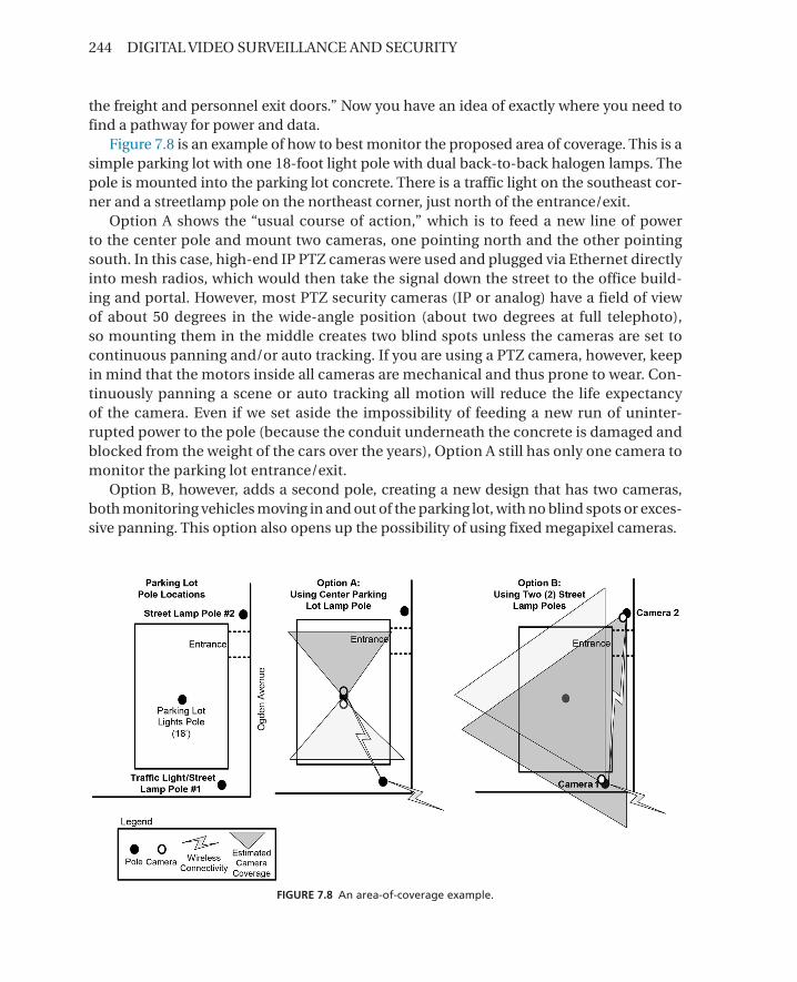
Figure 7.8 is an example of how to best monitor the proposed area of coverage. This is a simple parking lot with one 18-foot light pole with dual back-to-back halogen lamps. The pole is mounted into the parking lot concrete. There is a traffic light on the southeast cor-ner and a streetlamp pole on the northeast corner, just north of the entrance/exit.
Option A shows the “usual course of action,” which is to feed a new line of power to the center pole and mount two cameras, one pointing north and the other pointing south. In this case, high-end IP PTZ cameras were used and plugged via Ethernet directly into mesh radios, which would then take the signal down the street to the office build-ing and portal. However, most PTZ security cameras (IP or analog) have a field of view of about 50 degrees in the wide-angle position (about two degrees at full telephoto), so mounting them in the middle creates two blind spots unless the cameras are set to continuous panning and/or auto tracking. If you are using a PTZ camera, however, keep in mind that the motors inside all cameras are mechanical and thus prone to wear. Con-tinuously panning a scene or auto tracking all motion will reduce the life expectancy of the camera. Even if we set aside the impossibility of feeding a new run of uninter-rupted power to the pole (because the conduit underneath the concrete is damaged and blocked from the weight of the cars over the years), Option A still has only one camera to monitor the parking lot entrance/exit.
Option B, however, adds a second pole, creating a new design that has two cameras, both monitoring vehicles moving in and out of the parking lot, with no blind spots or exces-sive panning. This option also opens up the possibility of using fixed megapixel cameras.
FIGURE 7.8 An area-of-coverage example.

Chapter 7 • Site Surveys 245
Network Infrastructure Site SurveysThe flow diagram shown in Figure 7.9 outlines the basic requirements of the network infra-structure survey procedures.
The purpose of a network infrastructure site survey is to analyze possible data routes (fiber and/or twisted pair) from the camera locations to the IDFs and back to the primary MDF, where the servers and storage are located. This survey may also include details about interconnectivity of separate building locations on a campus environment or across streets and neighborhoods. This process begins with detailed plans, topologies, schematics, and diagrams of any and all common data and electrical pathways and duct banks. This first step will provide identification of actual data pathways on campus. Once those pathways are identified and documented, the site survey team (teams, plural, for a large implemen-tation using concurrent activities) analyzes maps and the physical underground routes to validate the findings. The team will then map proposed data routes from the camera, IDF, and MDF locations. These proposed routes will be compiled in the network infrastructure site survey for approval.
Interim Distribution Facility
An interim distribution facility (IDF) is a data intersection between camera locations and the primary server and storage data center, or main distribution facility (MDF). The IDF can be a data closet where a rack or cabinet resides for Internet or telephone connections or even part of an old CCTV installation (see Figure 7.10) and is usually environmentally friendly (e.g., air conditioned and dry). An IDF should never be located under large plumb-ing banks, in basements, or in attics—nowhere that can be flooded or that can achieve extreme heat. The more networking equipment added to any IDF (or MDF) closet or room, the more the room’s temperature will increase, and heat dissipation must be considered.
Perform
Site Survey
Document Site
Survey Results
Communicate
Site Survey
Information
and Form
Deploy
Survey Team
Schedule Site
Survey Team
for
Assessment
Meeting
Gather Existing
Documentation,
Drawings
& Diagrams
Clarify Goals
& Objectives
& Identified
Locations
General
Site Survey
Process
Identify and
Assign
Survey Teams
FIGURE 7.9 The network infrastructure survey process.
CABLE TAGGING
To clearly identify the cables during installation, the dedicated existing cabling, new cabling, and the splices should be tagged by their specific functions. These tags should be photographed and added to the site survey form or installation documentation to clarify to the contractor which cables must be used for the implementation.

246 DIGITAL VIDEO SURVEILLANCE AND SECURITY
The purpose of IDF surveys is to evaluate the customer-suggested site list for each IDF and to gain a thorough understanding of the physical aspects of the MDF and selected IDF sites from the standpoint of equipment installation and connectivity. The survey process starts with the identification of a potential IDF and the number of cameras that will termi-nate at that location. Considerations include geographic location, proximity to a range of cameras, accessibility and security, suitability for support of networking and networking equipment, and time to results.
Details from the site survey should always be documented in a network infrastruc-ture site survey form in a standardized format using standardized terminology. The forms include a collection of logical network information (IP addresses, VLANs, etc.), physical location, rack diagrams, patch panels and cable entry/exit points, HVAC and power capacity, and contact and security details for future reentry and service requirements.
Main Distribution Facility
The MDF is the heart of the DVS system, housing its server and storage equipment. It should be in a highly secure location, be environmentally controlled, and include enough floor and/or rack space to hold the newly required equipment (see Figure 7.11).
FIGURE 7.10 An example of a CCTV installation requiring a DVS upgrade. Sometimes the biggest challenge is uncovering the cameras that are still operational.
ISOLATE THE DVS NETWORK
Either by virtual configurations (VLANs) or by physical hardware, it’s best to isolate the DVS network from the rest of the business networks, since sharing bandwidth with sites like YouTube and other Internet trafficking may degrade the way the DVS system functions. Do not inherit a poorly designed network, because it will reflect on the DVS system.

Chapter 7 • Site Surveys 247
Fiber Patch Panel /SC
Ethernet (Cat5)Patch Panel
Power Strip
Smart UPS
PDU for Cameras
Ethernet Switch
Fiber Patch Panel /SC
Ethernet (Cat5)Patch Panel
Smart UPS
Smart UPS
Fiber Cameras: 0 Copper Cameras: 9
Integrated Cameras (Coaxial to Encoder): 5
Total Cameras: 14
Multi-Port Encoder
12/07/2009 v5.3IDF 112 File Name: Rack Elevation IDF 112
Current After
List of New Equipment:
FIGURE 7.11 This example rack diagram shows how the DVS implementation will change the IDF rack or cabinet.

248 DIGITAL VIDEO SURVEILLANCE AND SECURITY
If rackmount equipment will be used, measure the height and width of the equipment rack and any available space that is required (e.g., 7-foot, 19-inch Chatsworth relay racks). Rack-mount battery UPS backup systems can weigh in excess of 1,000 pounds, so make sure the specifications of the rack equipment can handle the weight of the accompanying equipment.
Power and Grounding
The required power is entirely based on the type and amount of equipment needed to accomplish the project objectives. Heavy equipment use in the MDF may require as much as two 30 AMP, 208/220/240 volt circuits and one 20 AMP, 110/120 volt circuit terminating in a 1U rackmounted six-outlet power strip. Remember that whatever the specifications, you should install a dedicated circuit for the required equipment so as not to be at the mercy of the existing electrical circuit.
Grounding electricity refers to the voltage level of zero potential through a chassis ground to the Earth to safeguard equipment from a buildup of static electricity or a power surge. If we’ve grounded the power, instead of frying all the equipment the surge just trips the (dedicated) circuit breaker. A building ground to the relay rack should already exist if professional networking equipment already exists within the IDF and MDF. The ground should be terminated on a copper ground bar, and if there isn’t one, don’t inherit this potential disaster! Create your own copper ground bar.
Wireless Site SurveysAs mentioned in the previous chapter, the term wireless does not mean there are no wires. The wireless site survey is an add-on to the previous site surveys to examine another option for delivering data, but there is still the need for power and connectivity back to the MDF. If there is available power to a required location but data is a problem or too cost prohibitive, that’s when wireless becomes a cost-effective solution.
Tools required for a wireless site survey include:
• One spectrum analyzer • Two bucket trucks (optional) • Two laptop computers • Two wireless radios • Two 6-foot coax jumpers • Two omnidirectional antennas
SHIPPING AND RECEIVING
Depending on the size of the DVS project, not only might skids of equipment be delivered, but they may need to be delivered to multiple locations and can weigh (with commercial UPS bat-tery backups) upward of 1,000 pounds. Make sure the destination is notified of the delivery, and remember to record who and when signed for it as received.
Chapter 7 • Site Surveys 249
• Two panel antennas • Two AC power invertors
A wireless site survey can be broken down into smaller phases, but in the end the pri-mary objective is to uncover all wireless activity in the area using the required frequencies (channels).
Pre-Survey Exploration
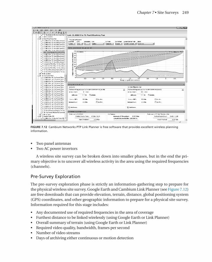
The pre-survey exploration phase is strictly an information-gathering step to prepare for the physical wireless site survey. Google Earth and Cambium Link Planner (see Figure 7.12) are free downloads that can provide elevation, terrain, distance, global positioning system (GPS) coordinates, and other geographic information to prepare for a physical site survey. Information required for this stage includes:
• Any documented use of required frequencies in the area of coverage • Furthest distance to be linked wirelessly (using Google Earth or Link Planner) • Overall summary of terrain (using Google Earth or Link Planner) • Required video quality, bandwidth, frames per second • Number of video streams • Days of archiving either continuous or motion detection
FIGURE 7.12 Cambium Networks PTP Link Planner is free software that provides excellent wireless planning information.

250 DIGITAL VIDEO SURVEILLANCE AND SECURITY
Once this information is gathered, it will create the baseline of power and wireless
equipment required to achieve your objectives. Google Earth (or Google Earth Pro, which offers a high-resolution printing feature for maximum detail) or Link Planner provides a means of visually documenting the data, terrain, distance, and line of sight, taking note of other wireless access points and radios uncovered using the spectrum analyzer (Figure 7.13). Keep in mind that all spectrum analyzers are not created equal. I’ve found many of the spectrum analyzers built into radios useful but wanting because they are limited in their capabilities and quality.
Radio Frequency Spectrum Analysis
As explained in the previous chapter, interference from other wireless equipment is the biggest reason for wireless network failures and problems during either initial deployment or once the network has been established. Couple that with the constant demand for bandwidth-hungry streaming video and I’ve discovered that there is no such thing as too much information. In all my years in DVS, rarely do I find that there’s a single fix causing
FIGURE 7.13 The Rohde & Schwarz FSH6 Spectrum Analyzer can detect any RF frequency up to 6 GHz.

Chapter 7 • Site Surveys 251
deployment or operational problems. When deploying a wireless mesh networking solu-tion for video surveillance, remember that DVS is synchronous, real-time, and bandwidth intensive, and you’re going to do this over half-duplex wireless mesh networking (see Chapter 5).
Gathering all the information prior to deployment saves hours of troubleshooting later. For example, during implementation of a wireless mesh with a few interconnected cam-eras in a point-to-multipoint architecture, if you are aware of other radios within the area using the same frequency, it will save time if you skip a few troubleshooting steps to chang-ing the channel to see what happens.
Most of my recent work is in the public security 4.9 GHz frequency. That’s a good thing because it’s only 50 MHz in size, but it’s also a bad thing because it’s only 50 MHz in size. The benefit of a closed, licensed frequency is that there isn’t much usage. Booting up a wireless-enabled laptop and scanning the available access points in a city the size of Chicago can bring up hundreds of access points in certain areas, depending on the power of the antenna. These APs are using the unlicensed frequencies such as 2.4 GHz and 5.0 GHz.
Figure 7.14 shows a photo of my “wireless mobile.” I’ve set up a number of antennas, each with a purpose and stage of the overall spectrum analysis. The omnidirectional, which
FIGURE 7.14 Wireless mobile has multiple antennas for specific functions, all at arm’s reach of the spectrum analyzer.

252 DIGITAL VIDEO SURVEILLANCE AND SECURITY
reads 360 degrees in the select frequency, shows whether anyone is using that frequency anywhere in the area. The sector antennas, either 90 or 45 degrees, will help in determin-ing from what direction those signals are coming. Finally, the powerful and laser-focused (10 degrees) panel antenna gives a more exact location. This helps in the overall design by selecting different channels and/or frequencies for the antennas pointing in that direction or to cross-polarize the antenna to further protect the signal (see Chapter 5).
Point-to-Point Mesh Radio Tests
If there is heavy usage of the required frequencies, the best practice is to set up a live point-to-point radio survey. By using actual radios with select antennas, a temporary point-to-point wireless connection is made to test actual wireless bandwidth, signal strength, RSSI, and video quality between the two units using a select number of channels that, during the spectrum analysis, were not in use. The best method of doing a point-to-point wireless test is to use two bucket trucks so as to raise the actual radios and antennas to the desired height in order to achieve a truly accurate test. If the radios are to be installed between buildings in close proximity to each other and can serve as a RF valley, the bucket truck test is unneces-sary. However, if the cameras and radios are to be mounted on the roof of these buildings, which are above the treetops, then the more information, the better. You could find that the required frequencies may be far too busy and so other options need to be explored.
During the pre-survey stage, the mesh portal (or master) location is determined. This portal is the radio that links the wireless network into the wired network. That location can become the hub, with a number of select locations (all within the requirements for the area of coverage) being the second radio, whether on your SUV or on a truck. These tests are simple pass or fail, with detailed documentation of how well each point passed in RSSI and bandwidth.
Wireless Survey Results
The wireless collected data is in addition to the official site survey form, since the point of the radio is to deliver video streams from the camera to a wired location, negating any installing, trenching or boring new conduit for data pathways, or clearing existing blocked conduit pathways.
The following information should be added in detail for each radio location:
• Antenna type • Antenna height (from ground level) • Antenna orientation (if directional is used) • Coaxial cable length from e-box to antenna (if not mounted to box) • Current radio SNR readings for each radio • Spectrum analysis: note any possible interference • Exact frequency and manufacturer’s channel
Site Survey Tools
The successful completion of a site survey, whether wired or wireless, requires a select number of tools. Those tools can be hardware and software tools and can be as complex

Chapter 7 • Site Surveys 253
as a laptop or as simple as a crowbar. Nevertheless, these tools are important to have on hand when you’re visiting potential sites so you can at least avoid having to return with the required tool. One of the most important of these tools is a digital camera. Taking photos of everything from racks, power, cabling, and equipment to climate control provides valuable reference when you’re later working on the architectural design and avoiding another revisit.
Those tools may include:
• Laptop • Hardware: • Built-in Ethernet and wireless adapters • RS-232 serial port or USB with RS-232 adapter • USB ports • Dual processor • High-performance video graphics card • Software: • Windows with latest service pack, antivirus software • Turn off all firewall software • Video management software client • Wireless mesh network management software • Microsoft Visio, Word, Excel • Adobe Acrobat • Adobe Photoshop or other image-editing software • Google Earth • Wireless propagation software • Hardware tools: • General tools (e.g., hammer, tape measure, pliers, etc.) • Crescent wrench • Screwdriver set • Nut drivers • Crowbar • Zip ties • Alligator clamps • Digital camera • Interteam communications tools (mobile phone) • Spectrum analyzer
Laptops
The field laptop is a simple laptop running the latest version of Windows that is compatible with whatever software tools required to accomplish the task. As depicted in Figure 7.15, you’ll have notes and site survey forms to complete while on site, requiring a laptop for recording that gathered information. (See Chapter 6 for more specific site survey processes.)
A built-in Ethernet and wireless network adapter, required for many site survey applications, becomes the hardware vehicle for gathering information on the wireless

254 DIGITAL VIDEO SURVEILLANCE AND SECURITY
CameraSite Survey
Process
Survey and Validate Availability of Above
and Underground Conduit Pathways for
Power and Data
ProvideFloor Plans,
Infrastructure Maps, Network Topology and
Diagrams, Schematics
Site Survey Readiness Checklist
Coordinate Schedule and Communicate
Document in Site Survey Form
Provide Camera Locations
(Customer orJoint Effort)
Secondary Location
Primary Location
Choose Primary and Secondary Locations
Shoot Digital Photos of Primary
and Secondary Location
Record Digital Photos from
Cameras on Site Survey
Equipment
Yes
Yes
NoNo
Yes
No
Secondary Location
Primary Location
YesNo
Yes
No
DVS Camera Site Survey Process
Go-No-Go
Perform Quality Inspection of
Data
Assemble Site Survey Team
System Integrator
Customer
Responsibility Color Code
Perform Quality
Inspection of Data
Yes
No
Map out Proposed Routes from IDF to
Camera Location
Power and Data Pathways
Area of Coverage
Review Provided
Documents
FIGURE 7.15 Site survey flowchart.

Chapter 7 • Site Surveys 255
environment. However, having a separate PC card or wireless adapter is not necessarily a bad choice, especially if you can attach a higher-power antenna to it.
This field laptop will also require the basic software necessities for documentation and deliverables, so an application suite such as Microsoft Office would be required, as would a copy of Adobe Acrobat, to convert those documents into noneditable deliverables (or just to shrink them down to email size).
Adobe Photoshop can be used to take screen captures and upsample them larger for print. A screen capture can be done in Windows by pressing and holding the Ctrl key and then press-ing the Print Screen/Sys Rq key, just right of F12. This action saves a copy of the screen on the Clipboard. Create a new document in Photoshop and then press and hold Ctrl key again, simultaneously pressing the V key to paste the screen capture into a new Photoshop image (or you can use Microsoft Paint, included within the Microsoft operating system software).
Google Earth (free version) can also provide a satellite view of the area of coverage as research or for documentation purposes. Google Earth Pro (licensed version) also includes the ability to save high-resolution files of the images; this capability alone makes it worth the cost of the license. There are also wireless planning applications, which, using input informa-tion, can provide an overall visual image of the coverage area of the wireless implementation.
There are many developers of wireless propagation (see Figure 7.16) and/or spec-trum analysis software, including companies such as Motorola (www.motorola.com/rfdesign) and Visiwave (www.visiwave.com). Basic link planning applications can assist in
FIGURE 7.16 Wireless propagation software over an image of Google Earth Pro. (Photo used with permission of VisiWave and Google.)

256 DIGITAL VIDEO SURVEILLANCE AND SECURITY
proliferation of wireless access points to provide full coverage to a select area, but the more sophisticated (and expensive) applications offer more flexibility and reporting func-tions, which alone can save valuable time in creating a wireless site survey document from scratch.
Hardware Tools
When you’re out doing a site survey, part of the objective is to explore. The reason for this is to uncover the best possible way of reaching the system requirements. How embarrassing would it be to design a solution that needs a 1,000 feet of new parallel conduit when during the install a spare pair was uncovered? This is why you need your toolbox, along with a few other select tools. Most of my site surveys are outdoors, so I found a crowbar to be a valuable asset—so much so that I’m on my third one (you know, I lend it to someone but never get it back).
It got to the point that I decided to buy a second set of my preferred tools (the ones I’ve become familiar with and accustomed to) just to keep in my mobile vehicle. I’ve also found that temporary banding products, such as zip ties in various sizes and industrial alligator clamps, always come in handy for mounting antennas to record point-to-point RSSI signals.
Digital Camera
The site survey typically becomes a document deliverable and as such, it requires details on the findings and recommendations. Thanks to digital photography, photographically recording area-of-coverage, obstacles, discoveries, and specific camera installation loca-tions is fast, cheap, and easy. A single photograph of an obstruction includes the thousand words of description an image can provide. Always bring a digital camera whenever you’re doing a site survey. It also helps to write notes that cross-reference your photos, to refresh your memory later.
Communications
Depending entirely on the size of the implementation, there could be more than one active site survey team. This is when interpersonal communication is crucial for sharing important information. This can be accomplished (as usual) using a cellular phone or
DIGITAL CAMERA POWER
There you are, with your customer, walking the area of coverage where she points out those unique areas that she needs monitored to improve the security and safety of the facility(s). These are very select locations, and they are many. Good thing you have your digital camera to record these nuances in the customer’s system requirements, but alas, upon pulling out your fancy digital pocket camera, you discover that the rechargeable battery is dead.
This is why I always carry a spare high-quality digital pocket camera that uses AA batteries and carry extra batteries with me. I went through two sets of AAs in Dallas just this week.

Chapter 7 • Site Surveys 257
walkie-talkie, but the exchange of contact information is important, not only to the dis-covery but to the documentation later.
Chapter Lessons • It’s an exploration of discovery, with the prime objective being meeting the system
requirements in the best and most cost-effective way. • Camera, data, power, and network site surveys are required as a bare minimum for a
DVS system. • The more details you gather, the more useful the information, so fill out a complete site
survey form for each camera location and take lots of photos.