digital video broadcasting (dvb); specification for the ... · digital video broadcasting (dvb);...
TRANSCRIPT

Digital Video Broadcasting (DVB); Specification for the carriage of synchronised auxiliary
data in DVB transport streams
DVB Document A094
June 2016

DVB BlueBook A094
3
Contents Intellectual Property Rights ................................................................................................................................ 5 Foreword............................................................................................................................................................. 5 Introduction ........................................................................................................................................................ 5 1 Scope ........................................................................................................................................................ 6 2 References ................................................................................................................................................ 6 3 Definitions and abbreviations ................................................................................................................... 6 3.1 Definitions ......................................................................................................................................................... 6 3.2 Abbreviations ..................................................................................................................................................... 6 4 Carriage of synchronised auxiliary data ................................................................................................... 7 4.1 Introduction........................................................................................................................................................ 7 4.2 Transport Stream (TS) packet format ................................................................................................................ 7 4.3 PES packet format ............................................................................................................................................. 7 4.4 Stream location .................................................................................................................................................. 8 4.5 Auxiliary data structure ..................................................................................................................................... 8 5 Descriptors ............................................................................................................................................... 9 5.1 Descriptor identification .................................................................................................................................... 9 5.2 Descriptor definitions ........................................................................................................................................ 9 5.2.1 TVA_id descriptor ....................................................................................................................................... 9 5.2.1.1 Usage ...................................................................................................................................................... 9 5.2.1.2 Syntax ..................................................................................................................................................... 9 5.2.1.3 Semantics ................................................................................................................................................ 9 5.2.2 Broadcast timeline descriptor ....................................................................................................................... 9 5.2.2.1 Introduction ............................................................................................................................................ 9 5.2.2.2 Usage .................................................................................................................................................... 10 5.2.2.3 Syntax ................................................................................................................................................... 13 5.2.2.4 Semantics .............................................................................................................................................. 13 5.2.3 Time base mapping descriptor ................................................................................................................... 15 5.2.3.1 Usage .................................................................................................................................................... 15 5.2.3.2 Syntax ................................................................................................................................................... 15 5.2.3.3 Semantics .............................................................................................................................................. 15 5.2.4 Content labeling descriptor ........................................................................................................................ 15 5.2.4.1 Usage .................................................................................................................................................... 15 5.2.4.2 Syntax ................................................................................................................................................... 16 5.2.4.3 Semantics .............................................................................................................................................. 16 5.2.4.4 PSI Signalling ....................................................................................................................................... 17 5.2.5 Synchronised event descriptor.................................................................................................................... 18 5.2.5.1 Usage .................................................................................................................................................... 18 5.2.5.2 Syntax ................................................................................................................................................... 18 5.2.5.3 Semantics .............................................................................................................................................. 19 5.2.6 Synchronised event cancel descriptor ........................................................................................................ 20 5.2.6.1 Usage .................................................................................................................................................... 20 5.2.6.2 Syntax ................................................................................................................................................... 21 5.2.6.3 Semantics .............................................................................................................................................. 21 Annex A: Timeline types ................................................................................................................................ 22 A.1 Metadata content timeline (normative) ...................................................................................................... 22 A.2 Broadcast timeline (normative) ................................................................................................................. 23 A.3 IEC-60461 time-code (informative) .......................................................................................................... 25 Annex B: Using broadcast timelines (informative)...................................................................................... 26 B.1 Multiple timelines .................................................................................................................................. 26 B.1.1 Introduction...................................................................................................................................................... 26

DVB BlueBook A094
4
B.1.2 Multiple timelines using direct timelines ......................................................................................................... 26 B.1.3 Multiple timelines using offset timelines ......................................................................................................... 26 B.2 Preventing advert detection .................................................................................................................... 27 Annex C: Broadcast timelines examples (informative) ............................................................................... 29 C.1 Direct broadcast timeline ....................................................................................................................... 29 C.2 Offset broadcast timeline ....................................................................................................................... 30 C.3 Implicit linking of a single broadcast timeline to an item of content ..................................................... 31 C.4 Associating multiple broadcast timelines with an item of content ......................................................... 32 Annex D: Broadcast timeline disruption in digital TV distribution systems (informative)..................... 34 D.1 Introduction ............................................................................................................................................ 34 D.2 Anticipated content insertion ................................................................................................................. 34 D.3 Unanticipated content insertion .............................................................................................................. 35 D.4 Recommendations for insertion ............................................................................................................. 35 D.5 Recommendations for receivers ............................................................................................................. 35 History .............................................................................................................................................................. 36 History box entries ............................................................................................................................................................ 36

DVB BlueBook A094
5
Intellectual Property Rights IPRs essential or potentially essential to the present document may have been declared to ETSI. The information pertaining to these essential IPRs, if any, is publicly available for ETSI members and non-members, and can be found in ETSI SR 000 314: "Intellectual Property Rights (IPRs); Essential, or potentially Essential, IPRs notified to ETSI in respect of ETSI standards", which is available from the ETSI Secretariat. Latest updates are available on the ETSI Web server (http://webapp.etsi.org/IPR/home.asp).
Pursuant to the ETSI IPR Policy, no investigation, including IPR searches, has been carried out by ETSI. No guarantee can be given as to the existence of other IPRs not referenced in ETSI SR 000 314 (or the updates on the ETSI Web server) which are, or may be, or may become, essential to the present document.
Foreword This European Standard (Telecommunications series) has been produced by Joint Technical Committee (JTC) Broadcast of the European Broadcasting Union (EBU), Comité Européen de Normalisation ELECtrotechnique (CENELEC) and the European Telecommunications Standards Institute (ETSI).
NOTE: The EBU/ETSI JTC Broadcast was established in 1990 to co-ordinate the drafting of standards in the specific field of broadcasting and related fields. Since 1995 the JTC Broadcast became a tripartite body by including in the Memorandum of Understanding also CENELEC, which is responsible for the standardization of radio and television receivers. The EBU is a professional association of broadcasting organizations whose work includes the co-ordination of its members' activities in the technical, legal, programme-making and programme-exchange domains. The EBU has active members in about 60 countries in the European broadcasting area; its headquarters is in Geneva.
European Broadcasting Union CH-1218 GRAND SACONNEX (Geneva) Switzerland Tel: +41 22 717 21 11 Fax: +41 22 717 24 81
The Digital Video Broadcasting Project (DVB) is an industry-led consortium of broadcasters, manufacturers, network operators, software developers, regulatory bodies, content owners and others committed to designing global standards for the delivery of digital television and data services. DVB fosters market driven solutions that meet the needs and economic circumstances of broadcast industry stakeholders and consumers. DVB standards cover all aspects of digital television from transmission through interfacing, conditional access and interactivity for digital video, audio and data. The consortium came together in 1993 to provide global standardisation, interoperability and future proof specifications.
Introduction The Moving Pictures Expert group (MPEG) has specified in ISO/IEC 13818-1 [1] how one or more elementary streams may be carried within a Transport Stream. The present document includes the definition of how two or more elementary streams of a particular service may be encoded so as observe the rules of a timing model and so ensure that they can be synchronised within the receiver. Whilst the description of this timing model focuses on video and audio, it is applicable to any kind of data stream. Existing Digital Video Broadcasting (DVB) specifications for conveying ITU-R System B Teletext in DVB bitstreams (see EN 300 472 [2] ) and Subtitling Systems (see EN 300 743 [3] ) already exploit this. However, they are not readily scalable so as to be applicable to the carriage of other kinds of “auxiliary” data that needs to be synchronised. Hence, the present document has been developed to address this issue and so provide a generic method for the carriage of synchronised auxiliary data in DVB transport streams.
DVB BlueBook A094
6
1 Scope The present document describes a method by which auxiliary data, which needs to be synchronised with linear components of a service, such as video and audio streams, may be carried in a DVB transport stream.
2 References [1] ITU-T Rec H.222 | ISO/IEC 13818-1 Information technology — Generic coding of moving
pictures and associated audio information: Systems.
[2] ETSI EN 300 472: Digital Video Broadcasting (DVB); Specification for conveying ITU-R System B Teletext in DVB bitstreams.
[3] ETSI EN 300 743: Digital Video Broadcasting (DVB); Subtitling systems.
[4] ETSI EN 300 468: Digital Video Broadcasting (DVB); Specification for Service Information (SI) in DVB systems.
[5] ETSI TS 102 323: Digital Video Broadcasting (DVB); Carriage and signalling of TV-Anytime information in DVB transport streams.
[6] ITU-T Rec H.262 | ISO/IEC 13818-2 Information technology — Generic coding of moving pictures and associated audio information: Video.
[7] Void.
[8] IEC 60461: Time and control code.
[9] ETSI TS 102 822-3-1 Broadcast and On-line Services: Search, select and rightful use of content on personal storage systems (“TV-Anytime Phase 1”), Part 3 Metadata, Sub-part 1: Metadata Schemas.
[10] ETSI TS 101 162: “Digital Video Broadcasting (DVB); Allocation of identifiers and codes for Digital Video Broadcasting (DVB) systems”
3 Definitions and abbreviations 3.1 Definitions For the purposes of the present document, the following terms and definitions apply:
broadcast timeline: a stream of data which conveys a metadata content timeline during the broadcast of an item of content. See Annex A.2.
metadata content timeline: the conceptual progress of time inherent in an item of content, which may be referred to by metadata and delivered by a broadcast timeline. See Annex A.1.
timebase: A data type used in TV-Anytime metadata for the purpose of referencing the metadata content timeline for an item of content. See ETSI TS 102 822-3-1 [9].
3.2 Abbreviations For the purposes of the present document, the following abbreviations apply:
CRC Cyclic Redundancy Check CRID Content Reference Identifier DSM-CC Digital Storage Media - Command & Control
NOTE: Defined in ISO/IEC 13818-6.
DVB Digital Video Broadcasting
DVB BlueBook A094
7
MPEG Moving Pictures Expert Group NPT Normal Play Time
NOTE: Defined in ISO/IEC 13818-6.
PES Packetized Elementary Stream PID Packet IDentifier PMT Program Map Table PSI Program Specific Information PTS Presentation Time Stamp PVR Personal Video Recorder SI Service Information STC System Time Clock
NOTE: Defined in ISO/IEC 13818-1 [1].
TS Transport Stream TV TeleVision TVA TV-Anytime
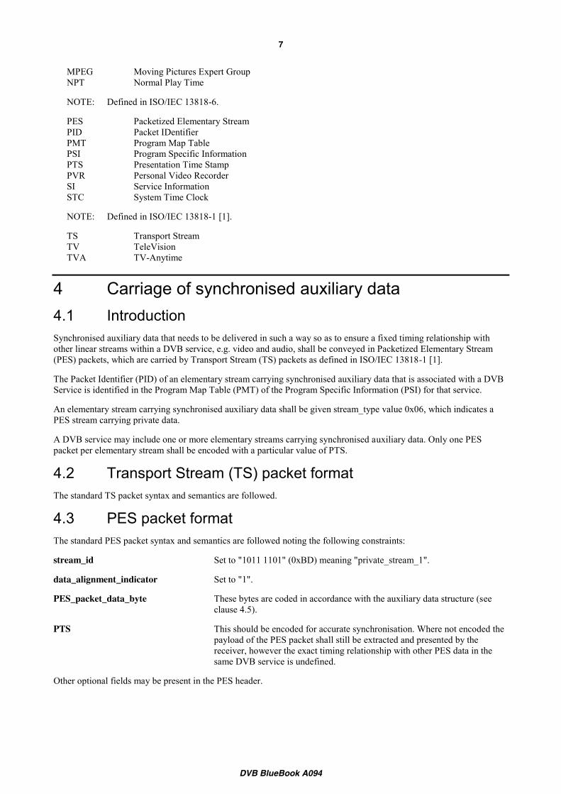
4 Carriage of synchronised auxiliary data 4.1 Introduction Synchronised auxiliary data that needs to be delivered in such a way so as to ensure a fixed timing relationship with other linear streams within a DVB service, e.g. video and audio, shall be conveyed in Packetized Elementary Stream (PES) packets, which are carried by Transport Stream (TS) packets as defined in ISO/IEC 13818-1 [1].
The Packet Identifier (PID) of an elementary stream carrying synchronised auxiliary data that is associated with a DVB Service is identified in the Program Map Table (PMT) of the Program Specific Information (PSI) for that service.
An elementary stream carrying synchronised auxiliary data shall be given stream_type value 0x06, which indicates a PES stream carrying private data.
A DVB service may include one or more elementary streams carrying synchronised auxiliary data. Only one PES packet per elementary stream shall be encoded with a particular value of PTS.
4.2 Transport Stream (TS) packet format The standard TS packet syntax and semantics are followed.
4.3 PES packet format The standard PES packet syntax and semantics are followed noting the following constraints:
stream_id Set to "1011 1101" (0xBD) meaning "private_stream_1".
data_alignment_indicator Set to "1".
PES_packet_data_byte These bytes are coded in accordance with the auxiliary data structure (see clause 4.5).
PTS This should be encoded for accurate synchronisation. Where not encoded the payload of the PES packet shall still be extracted and presented by the receiver, however the exact timing relationship with other PES data in the same DVB service is undefined.
Other optional fields may be present in the PES header.

DVB BlueBook A094
8
4.4 Stream location An elementary stream carrying synchronised auxiliary data will have the stream_type value 0x06 (see clause 4.1) and stream_id value 0xBD (see clause 4.3). However, this information may not always be sufficient to unambiguously locate a specific synchronized auxiliary data stream as there may be more than one elementary stream within a particular DVB Service with the same combination of stream_type and stream_id. Possible reasons for this are as follows:
x There may be more than one elementary stream within a particular DVB Service carrying synchronised auxiliary data (see clause 4.1).
x This combination of stream_type and stream_id can be used for applications other than the delivery of synchronised auxiliary data.
In such cases it will be necessary to provide a means to uniquely locate the relevant elementary stream other than by the combination of stream_type and stream_id. Hence synchronized auxiliary data streams shall be signalled using a data broadcast id descriptor in the PMT, using the data broadcast id value assigned to the present document by TS 101 162 [10]. If more than one synchronized auxiliary data streams are carried within a particular DVB service, they can be distinguished using the component_tag field in the stream identifier descriptor, or via use of the id selector bytes in the data broadcast id descriptor.
4.5 Auxiliary data structure The syntax for this stucture is defined by table 1.
Table 1: auxiliary data structure
Syntax No. of bits Identifier auxiliary_data_structure() { payload_format 4 uimsbf Reserved 3 uimsbf CRC_flag 1 uimsbf for (i=0; i<N; i++) { payload_byte 8 uimsbf } if ( CRC_flag == ‘1’) { CRC_32 32 uimsbf } }
NOTE: Since this structure is all that is carried by the PES_packet_data_bytes its size can be determined from the PES_packet_length and PES_header_data_length fields encoded within the PES packet structure.
payload_format: This 4-bit field identifies the format used for the encoding of the payload field, and is coded according to table 2.
Table 2: payload format
Value Meaning 0x0 DVB reserved 0x1 The payload field shall consist of zero or more descriptors from
those defined in clause 5 of the present document. 0x2-0x7 DVB reserved 0x8-0xF User private
CRC_flag: A 1-bit flag, which when set to '1' indicates that the CRC_32 field is present in the structure. When set to '0' it indicates that this field is not present.
payload_byte: This is an 8-bit field. The sequence of payload_bytes specifies the payload field. The syntax and semantics of payload field are defined within the context of the format that is identified in the payload_format field.
CRC_32: This 32-bit field contains the CRC value that gives a zero output of the registers in the decoder defined in annex B of EN 300 468 [4] after processing the entire auxiliary_data_structure.
DVB BlueBook A094
9
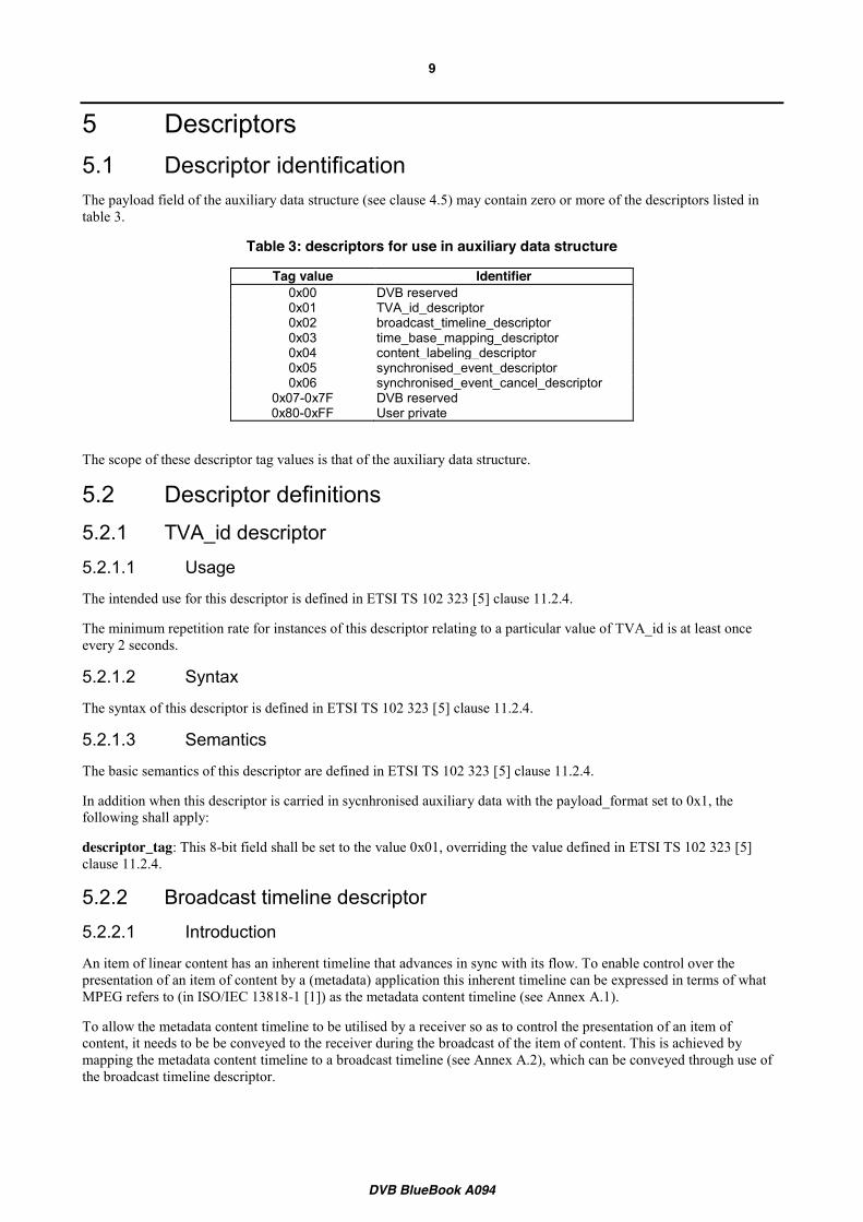
5 Descriptors 5.1 Descriptor identification The payload field of the auxiliary data structure (see clause 4.5) may contain zero or more of the descriptors listed in table 3.
Table 3: descriptors for use in auxiliary data structure
Tag value Identifier 0x00 DVB reserved 0x01 TVA_id_descriptor 0x02 broadcast_timeline_descriptor 0x03 time_base_mapping_descriptor 0x04 content_labeling_descriptor 0x05 synchronised_event_descriptor 0x06 synchronised_event_cancel_descriptor
0x07-0x7F DVB reserved 0x80-0xFF User private
The scope of these descriptor tag values is that of the auxiliary data structure.
5.2 Descriptor definitions 5.2.1 TVA_id descriptor 5.2.1.1 Usage
The intended use for this descriptor is defined in ETSI TS 102 323 [5] clause 11.2.4.
The minimum repetition rate for instances of this descriptor relating to a particular value of TVA_id is at least once every 2 seconds.
5.2.1.2 Syntax
The syntax of this descriptor is defined in ETSI TS 102 323 [5] clause 11.2.4.
5.2.1.3 Semantics
The basic semantics of this descriptor are defined in ETSI TS 102 323 [5] clause 11.2.4.
In addition when this descriptor is carried in sycnhronised auxiliary data with the payload_format set to 0x1, the following shall apply:
descriptor_tag: This 8-bit field shall be set to the value 0x01, overriding the value defined in ETSI TS 102 323 [5] clause 11.2.4.
5.2.2 Broadcast timeline descriptor 5.2.2.1 Introduction
An item of linear content has an inherent timeline that advances in sync with its flow. To enable control over the presentation of an item of content by a (metadata) application this inherent timeline can be expressed in terms of what MPEG refers to (in ISO/IEC 13818-1 [1]) as the metadata content timeline (see Annex A.1).
To allow the metadata content timeline to be utilised by a receiver so as to control the presentation of an item of content, it needs to be be conveyed to the receiver during the broadcast of the item of content. This is achieved by mapping the metadata content timeline to a broadcast timeline (see Annex A.2), which can be conveyed through use of the broadcast timeline descriptor.

DVB BlueBook A094
10
5.2.2.2 Usage
When carried within synchronised auxiliary data the broadcast timeline descriptor provides a means to accurately associate a value of time with a specific point in the broadcast. This provides a means to describe a broadcast timeline.
The broadcast timeline descriptor defines time in terms of a count of ticks. This unformatted tick count can be converted into a value of time using the tick format field, i.e. the number of ticks per unit of time. This allows the encoded value for the broadcast timeline to be converted into other formats for the representation of time as required (see Annex A.3).
NOTE: An unformatted tick count is used since it simplifies the task of processing time values in the receiver.
A broadcast timeline may be defined in two ways:
x As a direct broadcast timeline by the encoding of absolute values of time in a broadcast timeline descriptor.
x As an offset broadcast timeline by the encoding of an offset value of time in a broadcast timeline descriptor. This offset is applied to the absolute value of time defined by a direct broadcast timeline.
NOTE: This enables, for example, different broadcast timelines for a number of different items of content to be defined against a single, free running “station clock”.
A broadcast timeline can be identified by a broadcast_timeline_id, which shall be unique within the scope of the particular elementary stream conveying the synchronised auxiliary data in which the descriptor is being delivered. This does not rule out external references from making use of the broadcast_timeline_id.
NOTE: For a particular application it may be wise to use an identifier with a broader scope and some indirection within the synchronised auxiliary data itself, e.g. through use of the content labeling descriptor (see clause 5.2.4).
Within a particular synchronised auxiliary data stream different instances of the broadcast timeline descriptor may be delivered in the same or different auxiliary data structures. The broadcast timeline descriptor defining an offset broadcast timeline and the broadcast timeline descriptor defining the direct broadcast timeline referenced by the former need not be delivered in the same auxiliary data structure. However, they shall be delivered in the same synchronised auxiliary data stream.
The broadcast timeline descriptor defines a value for a broadcast timeline at a discrete point. To generate values for the broadcast timeline between received values this shall be achieved by extrapolation as follows:
Te = Tr + (Ts x Rr)
Where:
Te Extrapolated value for the broadcast timeline in ticks
Tr Received value for the broadcast timeline in ticks
Ts Time in seconds from the received value for which an extrapolated value is required.
Rr Rate of advancement of the broadcast timeline as defined by the received tick_rate
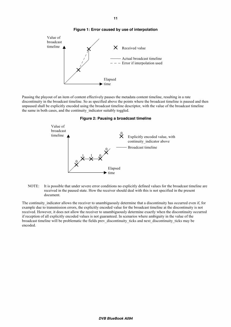
The use of extrapolation to determine values for the broadcast timeline other than those explicitly encoded relies on a constant rate of advancement. Any discontinuity in the broadcast timeline (regardless of whether in rate or value) represents a point beyond which extrapolation is not reliable. Consequently the value of the broadcast timeline at any discontinuity shall be explicitly encoded and the continuity_indicator shall be toggled compared to its state prior to the discontinuity.
NOTE: It is the potential occurrence of discontinuities that makes interpolation unreliable. See figure 1.
DVB BlueBook A094
11
Figure 1: Error caused by use of interpolation
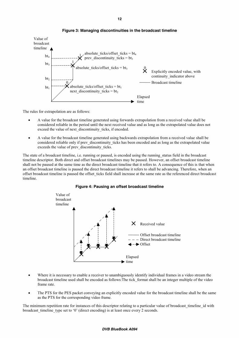
Pausing the playout of an item of content effectively pauses the metadata content timeline, resulting in a rate discontinuity in the broadcast timeline. So as specified above the points where the broadcast timeline is paused and then unpaused shall be explicitly encoded using the broadcast timeline descriptor, with the value of the broadcast timeline the same in both cases, and the continuity_indicator suitably toggled.
Figure 2: Pausing a broadcast timeline
NOTE: It is possible that under severe error conditions no explicitly defined values for the broadcast timeline are received in the paused state. How the receiver should deal with this is not specified in the present document.
The continuity_indicator allows the receiver to unambiguously determine that a discontinuity has occurred even if, for example due to transmission errors, the explicitly encoded value for the broadcast timeline at the discontinuity is not received. However, it does not allow the receiver to unambiguously determine exactly when the discontinuity occurred if reception of all explicitly encoded values is not guaranteed. In scenarios where ambiguity in the value of the broadcast timeline will be problematic the fields prev_discontinuity_ticks and next_discontinuity_ticks may be encoded.
Elapsed time
Value of broadcast timeline
Actual broadcast timeline Error if interpolation used
Received value
Elapsed time
Value of broadcast timeline Explicitly encoded value, with
continuity_indicator above Broadcast timeline
0 0
0
0
1 1
DVB BlueBook A094
12
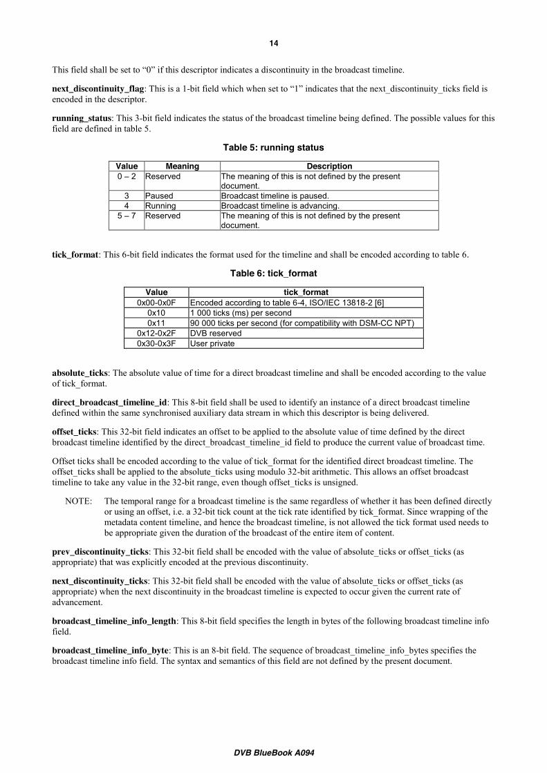
Figure 3: Managing discontinuities in the broadcast timeline
The rules for extrapolation are as follows:
x A value for the broadcast timeline generated using forwards extrapolation from a received value shall be considered reliable in the period until the next received value and as long as the extrapolated value does not exceed the value of next_discontinuity_ticks, if encoded.
x A value for the broadcast timeline generated using backwards extrapolation from a received value shall be considered reliable only if prev_discontinuity_ticks has been encoded and as long as the extrapolated value exceeds the value of prev_discontinuity_ticks.
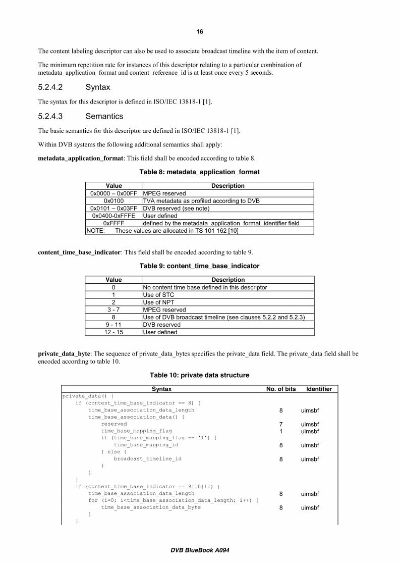
The state of a broadcast timeline, i.e. running or paused, is encoded using the running_status field in the broadcast timeline descriptor. Both direct and offset broadcast timelines may be paused. However, an offset broadcast timeline shall not be paused at the same time as the direct broadcast timeline that it refers to. A consequence of this is that when an offset broadcast timeline is paused the direct broadcast timeline it refers to shall be advancing. Therefore, when an offset broadcast timeline is paused the offset_ticks field shall increase at the same rate as the referenced direct broadcast timeline.
Figure 4: Pausing an offset broadcast timeline
x Where it is necessary to enable a receiver to unambiguously identify individual frames in a video stream the broadcast timeline used shall be encoded as follows:The tick_format shall be an integer multiple of the video frame rate.
x The PTS for the PES packet conveying an explicitly encoded value for the broadcast timeline shall be the same as the PTS for the corresponding video frame.
The minimum repetition rate for instances of this descriptor relating to a particular value of broadcast_timeline_id with broadcast_timeline_type set to ‘0’ (direct encoding) is at least once every 2 seconds.
Elapsed time
Value of broadcast timeline
Explicitly encoded value, with continuity_indicator above Broadcast timeline 0
0
1
1 bt3
bt2
absolute_ticks/offset_ticks = bt1 next_discontinuity_ticks = bt2
absolute_ticks/offset_ticks = bt3
absolute_ticks/offset_ticks = bt4 prev_discontinuity_ticks = bt3
bt1
bt4
Elapsed time
Value of broadcast timeline
Received value
Offset broadcast timeline Direct broadcast timeline Offset

DVB BlueBook A094
13
The minimum repetition rate for instances of this descriptor relating to a particular value of broadcast_timeline_id with broadcast_timeline_type set to ‘1’ (offset encoding) is at least once every 5 seconds.
5.2.2.3 Syntax
The syntax for this descriptor is defined by table 4.
Table 4: broadcast_timeline descriptor
Syntax No. of bits Identifier broadcast_timeline_descriptor() { descriptor_tag 8 uimsbf descriptor_length 8 uimsbf broadcast_timeline_id 8 uimsbf reserved 1 uimsbf broadcast_timeline_type 1 uimsbf continuity_indicator 1 uimsbf prev_discontinuity_flag 1 uimsbf next_discontinuity_flag 1 uimsbf running_status 3 uimsbf if (broadcast_timeline_type == ‘0’) { /* direct encoding */ reserved 2 uimsbf tick_format 6 uimsbf absolute_ticks 32 uimsbf } if (broadcast_timeline_type == ‘1’) { /* offset encoding */ direct_broadcast_timeline_id 8 uimsbf offset_ticks 32 Uimsbf } if (prev_discontinuity_flag == ‘1’) { prev_discontinuity_ticks 32 uimsbf } if (next_discontinuity_flag == ‘1’) { next_discontinuity_ticks 32 uimsbf } broadcast_timeline_info_length 8 Uimsbf for (i=0; i<broadcast_timeline_info_length; i++) { broadcast_timeline_info_byte 8 Uimsbf } }
5.2.2.4 Semantics
descriptor_tag: This 8-bit field shall be set to the value 0x02.
descriptor_length: This 8-bit field specifies the total number of bytes of the data portion of the descriptor following the byte defining the value of this field.
broadcast_timeline_id: This 8-bit field shall be used to uniquely identify the broadcast timeline being defined. The scope of uniqueness of this identifier is the elementary stream conveying the synchronised auxiliary data in which the descriptor is being delivered.
broadcast_timeline_type: This 1-bit field is used to identify the type of broadcast timeline being defined.
When set to ‘0’ a direct broadcast timeline is being defined. In this case an absolute value of time and the format used for this are both explicitly encoded.
When set to ‘1’ an offset broadcast timeline is being defined. In this case another broadcast timeline, of type direct, is identified and an offset to this encoded. The format for the encoding of this offset shall be the same as that used for the absolute time encoded in the identified direct broadcast timeline.
continuity_indicator: This 1-bit field is used to identify a sequence of values for a broadcast timeline that occur between discontinuities. Its state shall be toggled at each discontinuity that occurs.
prev_discontinuity_flag: This is a 1-bit field which when set to “1” indicates that the prev_discontinuity_ticks field is encoded in the descriptor.
DVB BlueBook A094
14
This field shall be set to “0” if this descriptor indicates a discontinuity in the broadcast timeline.
next_discontinuity_flag: This is a 1-bit field which when set to “1” indicates that the next_discontinuity_ticks field is encoded in the descriptor.
running_status: This 3-bit field indicates the status of the broadcast timeline being defined. The possible values for this field are defined in table 5.
Table 5: running status
Value Meaning Description 0 – 2 Reserved The meaning of this is not defined by the present
document. 3 Paused Broadcast timeline is paused. 4 Running Broadcast timeline is advancing.
5 – 7 Reserved The meaning of this is not defined by the present document.
tick_format: This 6-bit field indicates the format used for the timeline and shall be encoded according to table 6.
Table 6: tick_format
Value tick_format 0x00-0x0F Encoded according to table 6-4, ISO/IEC 13818-2 [6]
0x10 1 000 ticks (ms) per second 0x11 90 000 ticks per second (for compatibility with DSM-CC NPT)
0x12-0x2F DVB reserved 0x30-0x3F User private
absolute_ticks: The absolute value of time for a direct broadcast timeline and shall be encoded according to the value of tick_format.
direct_broadcast_timeline_id: This 8-bit field shall be used to identify an instance of a direct broadcast timeline defined within the same synchronised auxiliary data stream in which this descriptor is being delivered.
offset_ticks: This 32-bit field indicates an offset to be applied to the absolute value of time defined by the direct broadcast timeline identified by the direct_broadcast_timeline_id field to produce the current value of broadcast time.
Offset ticks shall be encoded according to the value of tick_format for the identified direct broadcast timeline. The offset_ticks shall be applied to the absolute_ticks using modulo 32-bit arithmetic. This allows an offset broadcast timeline to take any value in the 32-bit range, even though offset_ticks is unsigned.
NOTE: The temporal range for a broadcast timeline is the same regardless of whether it has been defined directly or using an offset, i.e. a 32-bit tick count at the tick rate identified by tick_format. Since wrapping of the metadata content timeline, and hence the broadcast timeline, is not allowed the tick format used needs to be appropriate given the duration of the broadcast of the entire item of content.
prev_discontinuity_ticks: This 32-bit field shall be encoded with the value of absolute_ticks or offset_ticks (as appropriate) that was explicitly encoded at the previous discontinuity.
next_discontinuity_ticks: This 32-bit field shall be encoded with the value of absolute_ticks or offset_ticks (as appropriate) when the next discontinuity in the broadcast timeline is expected to occur given the current rate of advancement.
broadcast_timeline_info_length: This 8-bit field specifies the length in bytes of the following broadcast timeline info field.
broadcast_timeline_info_byte: This is an 8-bit field. The sequence of broadcast_timeline_info_bytes specifies the broadcast timeline info field. The syntax and semantics of this field are not defined by the present document.

DVB BlueBook A094
15
5.2.3 Time base mapping descriptor 5.2.3.1 Usage
The time base mapping descriptor provides a means to explicitly associate an external time base with a broadcast timeline.
The minimum repetition rate for instances of this descriptor relating to a particular value of time_base_mapping_id is at least once every 5 seconds.
5.2.3.2 Syntax
The syntax for this descriptor is defined by table 7.
Table 7: time_base_mapping_descriptor
Syntax No. of bits Identifier time_base_mapping_descriptor() { descriptor_tag 8 uimsbf descriptor_length 8 uimsbf time_base_mapping_id 8 uimsbf reserved 1 uimsbf num_time_bases 7 uimsbf for (i=0; i<num_time_base; i++) { time_base_id 8 uimsbf broadcast_timeline_id 8 uimsbf } }
5.2.3.3 Semantics
descriptor_tag: This 8-bit field shall be set to the value 0x03.
descriptor_length: This 8-bit field specifies the total number of bytes of the data portion of the descriptor following the byte defining the value of this field.
time_base_mapping_id: This 8-bit field shall be used to uniquely identify a set of mappings between external time bases and broadcast timelines. The scope of uniqueness of this identifier is the elementary stream conveying the synchronised auxiliary data in which the descriptor is being delivered.
num_time_bases: This 7-bit field specifies the number of time base to broadcast timeline mappings defined.
The time bases shall be defined in ascending numerical order of time_base_id field.
time_base_id: This 8-bit field identifies the time base to be mapped.
broadcast_timeline_id: This 8-bit field shall be used to identify an instance of a broadcast timeline, which may be of type direct or offset, defined within the same synchronised auxiliary data steam (but not necessarily the same auxiliary data structure) in which this descriptor is being delivered.
5.2.4 Content labeling descriptor 5.2.4.1 Usage
The content labeling descriptor provides a means to associate a label, in the form of an identifier, to an item of content. This label can be used by metadata to reference the associated content. The format of the identifier can vary depending on the metadata application.
Within a particular synchronised auxiliary data stream different instances of the content labeling descriptor may be delivered in the same or different auxiliary data structure.
NOTE: The minimum repetition rate for the broadcast of instances of this descriptor can be used as part of the receiver’s strategy for determining whether or not an externally provided content identifier can be matched at the current moment.
DVB BlueBook A094
16
The content labeling descriptor can also be used to associate broadcast timeline with the item of content.
The minimum repetition rate for instances of this descriptor relating to a particular combination of metadata_application_format and content_reference_id is at least once every 5 seconds.
5.2.4.2 Syntax
The syntax for this descriptor is defined in ISO/IEC 13818-1 [1].
5.2.4.3 Semantics
The basic semantics for this descriptor are defined in ISO/IEC 13818-1 [1].
Within DVB systems the following additional semantics shall apply:
metadata_application_format: This field shall be encoded according to table 8.
Table 8: metadata_application_format
Value Description 0x0000 – 0x00FF MPEG reserved
0x0100 TVA metadata as profiled according to DVB 0x0101 – 0x03FF DVB reserved (see note) 0x0400-0xFFFE User defined
0xFFFF defined by the metadata_application_format_identifier field NOTE: These values are allocated in TS 101 162 [10]
content_time_base_indicator: This field shall be encoded according to table 9.
Table 9: content_time_base_indicator
Value Description 0 No content time base defined in this descriptor 1 Use of STC 2 Use of NPT
3 - 7 MPEG reserved 8 Use of DVB broadcast timeline (see clauses 5.2.2 and 5.2.3)
9 - 11 DVB reserved 12 - 15 User defined
private_data_byte: The sequence of private_data_bytes specifies the private_data field. The private_data field shall be encoded according to table 10.
Table 10: private data structure
Syntax No. of bits Identifier private_data() { if (content_time_base_indicator == 8) { time_base_association_data_length 8 uimsbf time_base_association_data() { reserved 7 uimsbf time_base_mapping_flag 1 uimsbf if (time_base_mapping_flag == ‘1’) { time_base_mapping_id 8 uimsbf } else { broadcast_timeline_id 8 uimsbf } } } if (content_time_base_indicator == 9|10|11) { time_base_association_data_length 8 uimsbf for (i=0; i<time_base_association_data_length; i++) { time_base_association_data_byte 8 uimsbf } }
DVB BlueBook A094
17
for (i=0; i<N; i++) { private_data_byte 8 uimsbf } }
time_base_association_data_length: This 8-bit field specifies the total number of bytes of the data portion of the structure following the byte defining the value of this field.
time_base_mapping_flag: This 1-bit field indicates if explicit mapping from external time base to broadcast timeline is provided.
If the time_base_mapping_flag is set to ‘1’ then explicit mapping is provided, which can be located using the encoded time_base_mapping_id.
If the time_base_mapping_flag is set to ‘0’ then no explicit mapping is provided and all time bases shall be mapped to a single broadcast timeline, which can be located using the encoded broadcast_timeline_id.
time_base_mapping_id: This 8-bit field shall be used to identify a set of time base to broadcast timeline mappings, delivered as the data portion of a time base mapping descriptor.
The relevant time base mapping descriptor shall be delivered within the same auxiliary data structure in which this descriptor is being delivered.
broadcast_timeline_id: This 8-bit field shall be used to identify an instance of a broadcast timeline, which may be of type direct or offset, defined within the same synchronised auxiliary data steam (but not necessarily the same auxiliary data structure) in which this descriptor is being delivered.
In addition when this descriptor is carried in sycnhronised auxiliary data with the payload_format set to 0x1, the following shall apply:
descriptor_tag: This 8-bit field shall be set to the value 0x04, overriding the value defined in ISO/IEC 13818-1 [1].
Further semantics will need to be defined within the context of the specific usage indicated by the encoding of the metadata application format. Such additional semantics are not defined within the present document.
5.2.4.4 PSI Signalling
To indicate that an elementary stream being used for synchronised auxiliary data conveys one or more content labeling descriptors relating to a particular metadata application (i.e. the same encoded metadata application format) a concise form of the content labeling descriptor may be placed in the corresponding ES_info structure (second descriptor loop) of the PMT. This shall be encoded as followed:
metadata_application_format: This field shall have the same value as encoded in the related content labeling descriptor instance(s) within the synchronised auxiliary data.
content_reference_id_record_flag: This 1-bit flag shall be set to ‘0’. Consequently no specific content reference id will be present in this instance of the descriptor.
content_time_base_indicator: This 4-bit field shall be set to 0. Consequently no content time base is defined in this descriptor.
NOTE: For this usage the descriptor tag used is as defined in ISO/IEC 13818-1 [1]. There may be more than one instance of this form of the content labeling descriptor within the ES_info structure for a particular elementary stream if the elementary stream itself conveys content labeling descriptors relating to more than one metadata application.
It is also possible that content labeling descriptors encoded with a particular value of metadata application format may be present within the ES_info structure for more than one elementary stream within a PMT. How this is dealt with is not specified here and is an issue for each particular metadata application: possible solutions include explicitly limiting carriage to a single elementary stream per PMT or making use of the private data field to discriminate between elementary streams.

DVB BlueBook A094
18
5.2.5 Synchronised event descriptor 5.2.5.1 Usage
The synchronised event descriptor contains information allowing the transmission of an application-specific event, the temporal reference of which needs to be synchronised with other components of the broadcast stream, i.e. a synchronised event.
NOTE: The definition of event in this context is a discrete temporal event and is not to be confused with the DVB Event entity as defined in EN 300 468 [4].
Each synchronised event is uniquely identified by the combination of synchronised_event_context, synchronised_event_id and synchronised_event_id_instance fields.
To allow synchronised events relating to more than one application context to be independently managed but still delivered within the same Synchronised Auxiliary Data stream, the syntax of the descriptor contains the synchronised_event_context field. This may be used to discriminate between different contexts.
Within each context, synchronised events of a particular type can be identified using the synchronised_event_id field. Hence the combination of synchronised_event_context and synchronised_event_id shall uniquely identify the type of synchronised event being described by the descriptor.
In common with other methods of delivering events, more than one instance of the synchronised event descriptor may be broadcast for a particular event as a means of reducing the effect of any transmission errors on the successful reception of the event. To provide a means to identify these instances the syntax of the descriptor contains the synchronised_event_id_instance field. This means that the combination of synchronised_event_id and synchronised_event_id_instance uniquely identifies instances of the descriptor relating a particular event.
Transmission instances of the descriptor associated with one synchronised event shall not be temporally interleaved with transmission instances of the descriptor associated with another synchronised event with the same encoded value of synchronised_event_context and synchronised_event_id. This would otherwise create the potential for the generation of spurious events by the receiver.
A side effect of allowing more than one instance of the descriptor to be broadcast for a particular event is that it introduces uncertainty as to the exact point in time that the event is associated with, i.e. depending on which of the instances of the descriptor is the first to be received. To provide a means to remove this uncertainty the syntax of the descriptor contains the reference_offset_ticks field. This field can be encoded with a temporal offset to be applied to the default temporal reference defined by the PTS of the PES packet in which the descriptor has been delivered. This allows different instances of the descriptor relating to a particular event to associate the same temporal reference with the synchronised event even if they are transmitted at different times, i.e. in different PES packets with varying PTS values.
This feature is not only useful for ensuring the successful reception of a synchronised event without introducing ambiguity in its temporal reference. It also allows the definition of the event to be communicated to the receiver in advance of its temporal reference where this is known, e.g. scheduled events for pre-recorded programmes. Provision of this information in advance can assist the receiver in its management and handling of such events.
The information provided by each instance of the descriptor relating to a particular synchronised event shall be consistent. Hence, the temporal reference for a particular synchronised event that is defined by one instance of the descriptor shall be as valid as that defined by any other instance of the descriptor relating to the same synchronised event.
5.2.5.2 Syntax
The syntax for this descriptor is defined by table 11.
Table 11: synchronised event descriptor
Syntax No. of bits Identifier synchronised_event_descriptor(){ descriptor_tag 8 uimsbf descriptor_length 8 uimsbf synchronised_event_context 8 uimsbf synchronised_event_id 16 uimsbf synchronised_event_id_instance 8 uimsbf Reserved 2
DVB BlueBook A094
19
tick_format 6 uimsbf reference_offset_ticks 16 tcimsbf synchronised_event_data_length 8 uimsbf for (j =0; j < N2; j++) { synchronised_event_data_byte 8 uimsbf } }
5.2.5.3 Semantics
descriptor_tag: This 8-bit field shall be set to the value 0x05.
descriptor_length: This 8-bit field specifies the total number of bytes of the data portion of the descriptor following the byte defining the value of this field.
synchronised_event_context: This 8-bit field shall identify the application-specific context for the synchronised event described by the descriptor. The allocation and meaning of the encoded value are outside the scope of the present document.
synchronised_event_id: This 16-bit field shall identify a type of synchronised event within the context identified by the synchronised_event_context. The allocation and meaning of the encoded value are outside the scope of the present document.
Values for synchronised_event_id in the range 0xFFF0-0xFFFF are reserved for DVB use and shall not be used within an application-specific context.
synchronised_event_id_instance: This 8-bit field shall be encoded with a single value for each instance of this descriptor relating to a particular synchronised event. Its value shall be incremented between each instance of a synchronised event of a particular type (i.e. the combination of synchronised_event_context, synchronised_event_id).
NOTE: Instances of synchronised events of different types, i.e. different synchronised_event_contexts and/or different synchronised_event_ids, may be allocated the same value of synchronised_event_id_instance.
NOTE: Since the synchronised_event_id_instance field is of finite size it may eventually wrap, resulting in re-use of a single allocated value for different synchronised events of the same type. This needs to be accommodated by receivers.
tick_format: This 6-bit field indicates the format used for the reference_offset_ticks, and shall be encoded according to table 6.
A single value of tick_format shall be used for all occurrences of this descriptor relating to a particular synchronised event.
reference_offset_ticks: This 16-bit field shall be encoded according to the value of tick_format.
The reference_offset_ticks field shall be encoded with a temporal offset that when applied to the default temporal reference defined by the PTS of the PES packet in which the descriptor has been delivered defines the temporal reference for the synchronised event.
A positive value of reference_offset_ticks shall be encoded if the temporal reference for the event is in the future with respect to the PTS of the PES packet in which the instance of this descriptor is delivered.
A negative value of reference_offset_ticks shall be encoded if the temporal reference for the event is in the past with respect to the PTS of the PES packet in which the instance of this descriptor is delivered.
DVB BlueBook A094
20
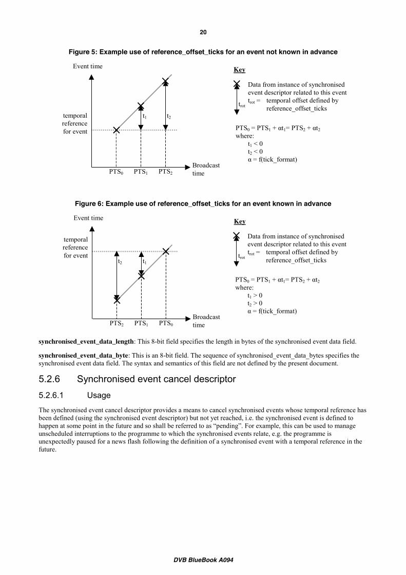
Figure 5: Example use of reference_offset_ticks for an event not known in advance
Figure 6: Example use of reference_offset_ticks for an event known in advance
synchronised_event_data_length: This 8-bit field specifies the length in bytes of the synchronised event data field.
synchronised_event_data_byte: This is an 8-bit field. The sequence of synchronised_event_data_bytes specifies the synchronised event data field. The syntax and semantics of this field are not defined by the present document.
5.2.6 Synchronised event cancel descriptor 5.2.6.1 Usage
The synchronised event cancel descriptor provides a means to cancel synchronised events whose temporal reference has been defined (using the synchronised event descriptor) but not yet reached, i.e. the synchronised event is defined to happen at some point in the future and so shall be referred to as “pending”. For example, this can be used to manage unscheduled interruptions to the programme to which the synchronised events relate, e.g. the programme is unexpectedly paused for a news flash following the definition of a synchronised event with a temporal reference in the future.
Broadcasttime
Event time
Data from instance of synchronised event descriptor related to this event trot = temporal offset defined by
reference_offset_ticks
PTS0 = PTS1 + αt1= PTS2 + αt2 where:
t1 < 0 t2 < 0 α = f(tick_format)
t1
PTS0 PTS1 PTS2
t2 temporal reference for event
trot
Key
Broadcasttime
Event time
Data from instance of synchronised event descriptor related to this event trot = temporal offset defined by
reference_offset_ticks
PTS0 = PTS1 + αt1= PTS2 + αt2 where:
t1 > 0 t2 > 0 α = f(tick_format)
t1
PTS2 PTS1 PTS0
t2
temporal reference for event trot
Key
DVB BlueBook A094
21
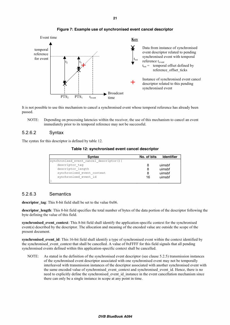
Figure 7: Example use of synchronised event cancel descriptor
It is not possible to use this mechanism to cancel a synchronised event whose temporal reference has already been passed.
NOTE: Depending on processing latencies within the receiver, the use of this mechanism to cancel an event immediately prior to its temporal reference may not be successful.
5.2.6.2 Syntax
The syntax for this descriptor is defined by table 12.
Table 12: synchronised event cancel descriptor
Syntax No. of bits Identifier synchronised_event_cancel_descriptor(){ descriptor_tag 8 uimsbf descriptor_length 8 uimsbf synchronised_event_context 8 uimsbf synchronised_event_id 16 uimsbf }
5.2.6.3 Semantics
descriptor_tag: This 8-bit field shall be set to the value 0x06.
descriptor_length: This 8-bit field specifies the total number of bytes of the data portion of the descriptor following the byte defining the value of this field.
synchronised_event_context: This 8-bit field shall identify the application-specific context for the synchronised event(s) described by the descriptor. The allocation and meaning of the encoded value are outside the scope of the present document.
synchronised_event_id: This 16-bit field shall identify a type of synchronised event within the context identified by the synchronised_event_context that shall be cancelled. A value of 0xFFFF for this field signals that all pending synchronised events defined within this application-specific context shall be cancelled.
NOTE: As stated in the definition of the synchronised event descriptor (see clause 5.2.5) transmission instances of the synchronised event descriptor associated with one synchronised event may not be temporally interleaved with transmission instances of the descriptor associated with another synchronised event with the same encoded value of synchronised_event_context and synchronised_event_id. Hence, there is no need to explicitly define the synchronised_event_id_instance in the event cancellation mechanism since there can only be a single instance in scope at any point in time.
Broadcasttime
Event time
Data from instance of synchronised event descriptor related to pending synchronised event with temporal reference tevent trot = temporal offset defined by
reference_offset_ticks
t1
PTS2 PTS1
t2
temporal reference for event trot
Key
tevent
Instance of synchronised event cancel descriptor related to this pending synchronised event

DVB BlueBook A094
22
Annex A: Timeline types
A.1 Metadata content timeline (normative) An item of linear content has an inherent timeline that advances in sync with its flow. To enable control over the presentation of an item of content by a (metadata) application this inherent timeline can be expressed in terms of what MPEG refers to (in ISO/IEC 13818-1 [1]) as the metadata content timeline.
To enable any point in an item of content to be unambiguously identified the value for the metadata content timeline associated with it shall be unique. To achieve this the following rules regarding the metadata content timeline shall be observed:
x An item of content is a continuous entity; hence the metadata content timeline associated with it shall be continuously advancing.
NOTE: Obviously during broadcast the playout of an item of content may be paused. However, when this occurs the metadata content timeline is inherently paused.
x The rate at which the metadata content timeline advances shall be both constant and positive.
NOTE: This precludes the wrapping of the metadata content timeline.
x Whatever units are used for the metadata content timeline it shall advance in sync with the flow of the item of content. I.e. the metadata content timeline shall be locked to the sampling clock of the item of content.
NOTE: This means that even if a standard unit of time is used for the metadata content timeline, e.g. milliseconds, the metadata content timeline advances in sync with the item of content even if the result is that it drifts with respect to time as determined by some other master system clock or even absolute time as determined by an atomic clock.
x Positive discontinuities in the value of the metadata content timeline may occur.
NOTE: This is to accommodate editorial use of timelines, e.g. start each new scene in a film on a significant value such as a whole number of minutes.
x The metadata content timeline may take any initial value, i.e. at the start of the item of content.
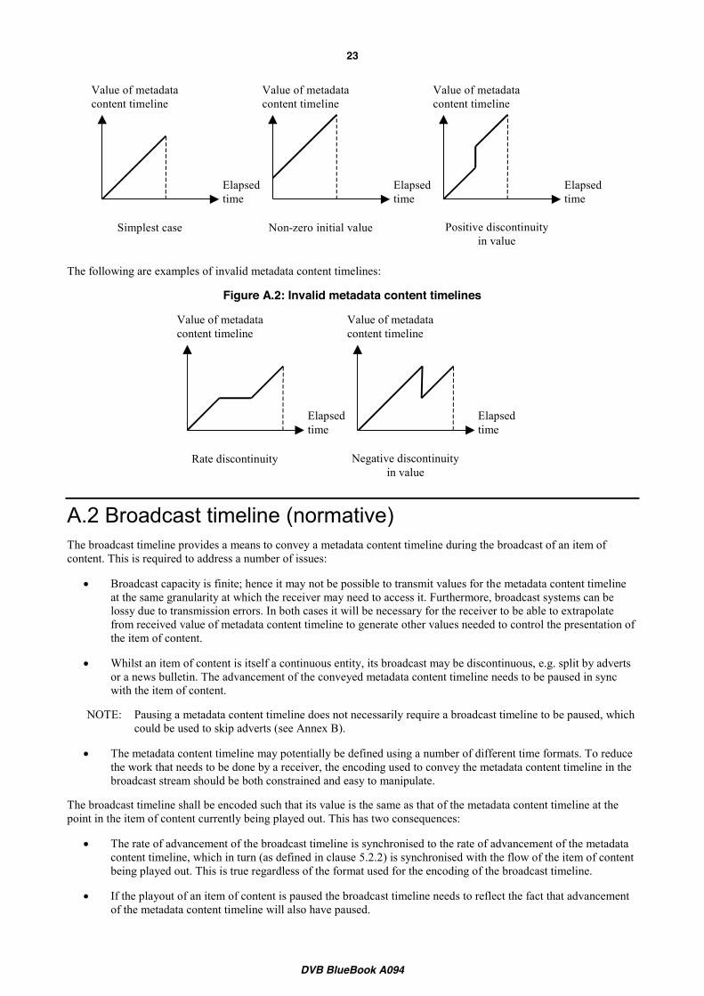
The following are examples of valid metadata content timelines:
Figure A.1: Valid metadata content timelines
DVB BlueBook A094
23
The following are examples of invalid metadata content timelines:
Figure A.2: Invalid metadata content timelines
A.2 Broadcast timeline (normative) The broadcast timeline provides a means to convey a metadata content timeline during the broadcast of an item of content. This is required to address a number of issues:
x Broadcast capacity is finite; hence it may not be possible to transmit values for the metadata content timeline at the same granularity at which the receiver may need to access it. Furthermore, broadcast systems can be lossy due to transmission errors. In both cases it will be necessary for the receiver to be able to extrapolate from received value of metadata content timeline to generate other values needed to control the presentation of the item of content.
x Whilst an item of content is itself a continuous entity, its broadcast may be discontinuous, e.g. split by adverts or a news bulletin. The advancement of the conveyed metadata content timeline needs to be paused in sync with the item of content.
NOTE: Pausing a metadata content timeline does not necessarily require a broadcast timeline to be paused, which could be used to skip adverts (see Annex B).
x The metadata content timeline may potentially be defined using a number of different time formats. To reduce the work that needs to be done by a receiver, the encoding used to convey the metadata content timeline in the broadcast stream should be both constrained and easy to manipulate.
The broadcast timeline shall be encoded such that its value is the same as that of the metadata content timeline at the point in the item of content currently being played out. This has two consequences:
x The rate of advancement of the broadcast timeline is synchronised to the rate of advancement of the metadata content timeline, which in turn (as defined in clause 5.2.2) is synchronised with the flow of the item of content being played out. This is true regardless of the format used for the encoding of the broadcast timeline.
x If the playout of an item of content is paused the broadcast timeline needs to reflect the fact that advancement of the metadata content timeline will also have paused.
Elapsed time
Value of metadata content timeline
Simplest case
Elapsed time
Value of metadata content timeline
Non-zero initial value
Elapsed time
Value of metadata content timeline
Positive discontinuity in value
Elapsed time
Value of metadata content timeline
Rate discontinuity
Elapsed time
Value of metadata content timeline
Negative discontinuity in value

DVB BlueBook A094
24
A broadcast timeline is conveyed through use of the broadcast timeline descriptor (see 5.2.2).

DVB BlueBook A094
25
A.3 IEC-60461 time-code (informative) A time-code is commonly embedded within video in the form of “HH:MM:SS:FF” as defined in IEC 60461 "Time and control codes for video tape recorders" [8]. As described in clause 5.2.2, broadcast timelines as defined by DVB are encoded using an unformatted tick count since it simplifies the task of processing time values in the receiver, particularly with respect to the offset encoding approach. This does not present a significant problem to the broadcaster or the receiver since embedded time-code in the video may be easily converted in timeline ticks and back again, e.g. 15260 ticks at 25 ticks per second could equally be represented as “00:10:10:10”.
It should be noted that at non-integer frame-rates, certain time-code values are skipped, which complicates any conversion. However, reliable conversion is still possible because the skipped values are deterministic, e.g. at 29.97 Hz picture numbers 0 and 1 at the start of each minute, except minutes 0, 10, 20, 30, 40, 50 are omitted from the count.
DVB BlueBook A094
26
Annex B: Using broadcast timelines (informative)
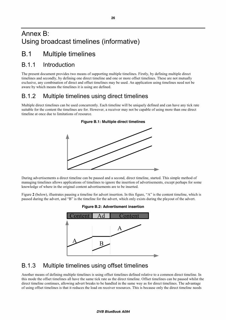
B.1 Multiple timelines B.1.1 Introduction The present document provides two means of supporting multiple timelines. Firstly, by defining multiple direct timelines and secondly, by defining one direct timeline and one or more offset timelines. These are not mutually exclusive, any combination of direct and offset timelines may be used. An application using timelines need not be aware by which means the timelines it is using are defined.
B.1.2 Multiple timelines using direct timelines Multiple direct timelines can be used concurrently. Each timeline will be uniquely defined and can have any tick rate suitable for the content the timelines are for. However, a receiver may not be capable of using more than one direct timeline at once due to limitations of resource.
Figure B.1: Multiple direct timelines
During advertisements a direct timeline can be paused and a second, direct timeline, started. This simple method of managing timelines allows applications of timelines to ignore the insertion of advertisements, except perhaps for some knowledge of where in the original content advertisements are to be inserted.
Figure 2 (below), illustrates pausing a timeline for advert insertion. In this figure, “A” is the content timeline, which is paused during the advert, and “B” is the timeline for the advert, which only exists during the playout of the advert.
Figure B.2: Advertisment insertion
B.1.3 Multiple timelines using offset timelines Another means of defining multiple timelines is using offset timelines defined relative to a common direct timeline. In this mode the offset timelines all have the same tick rate as the direct timeline. Offset timelines can be paused whilst the direct timeline continues, allowing advert breaks to be handled in the same way as for direct timelines. The advantage of using offset timelines is that it reduces the load on receiver resources. This is because only the direct timeline needs
A B
A
Content ContentAd

DVB BlueBook A094
27
to be managed in a real-time manner: the offset timelines are locked to the direct timeline. These benefits are minimised if pausing of offset timelines is used.
For example, figure 3 (below) shows three timelines. Timelines (S) is the studio clock broadcast as a direct timeline. Timelines (A) and (B) are offset timelines defined relative to the studio clock by offsets ∆A and ∆B, respectively.
Figure B.3: Multiple timelines using offsets
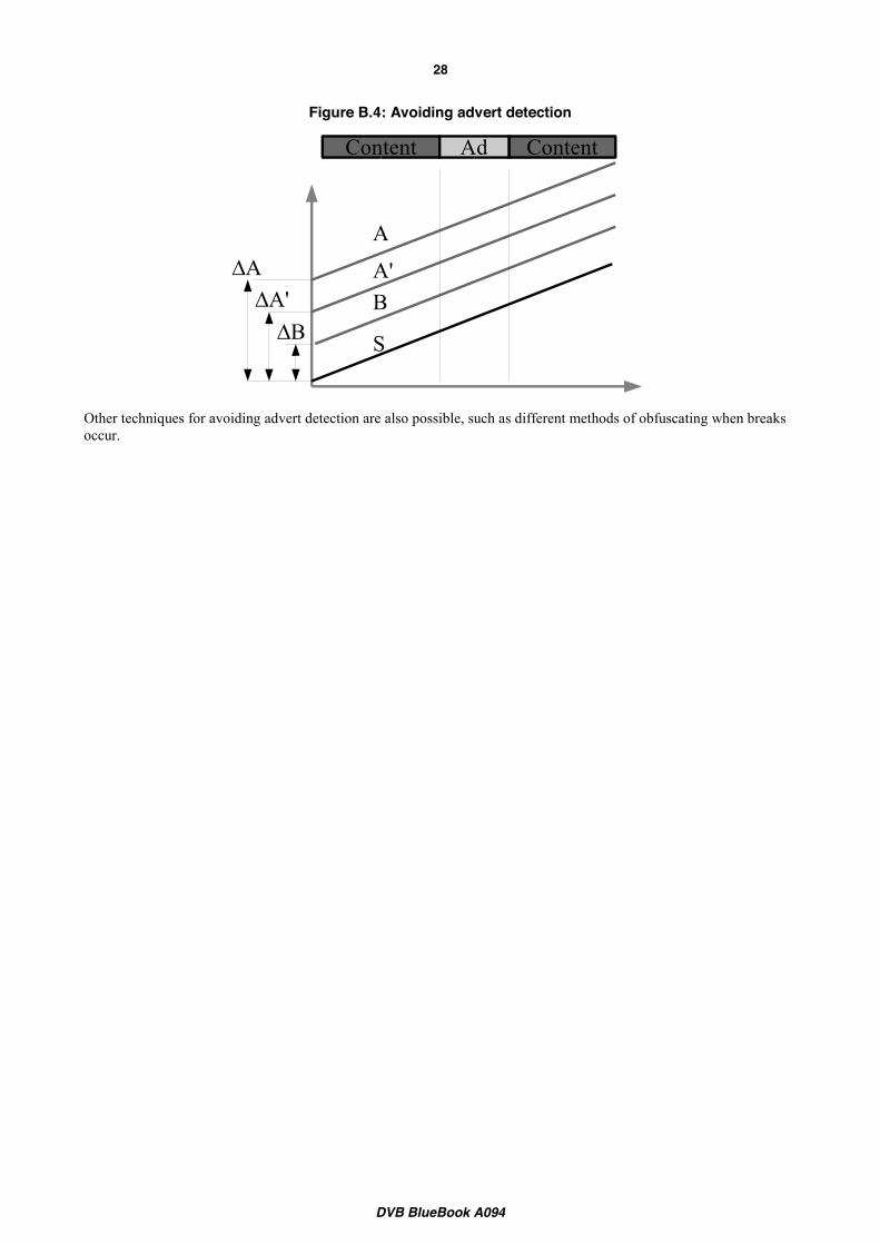
B.2 Preventing advert detection Pausing a broadcast timeline during advert breaks and inserting additional timelines (see figure 2) could provide a means for receivers to discover when breaks occur. In many networks this might be a problem since a PVR could use this information to skip advertisments during playback and thus put revenue from advertising at risk. The present document supports modes of operation that do not reveal where advertisments occur.
Typically a broadcaster will know before broadcast when adverts will be inserted within an item of content and exactly how long those adverts are. In this situation multiple offset timelines can be defined shortly before the start of broadcast. One broadcast timeline will be required for each part of the item of content and one for any advert that requires a timeline. Since these broadcast timelines run throughout the duration of the content without pausing it is impossible to assertain from the timelines when adverts will be inserted.
This method does require that any segmentation metadata or synchronised interactive application is authored using multiple timelines, which requires prior knowledge of when adverts are to be inserted but does not require prior knowledge of how long they will be.
For example, in figure 4 an item of content is shown in two parts. The timeline for the first part is (A) and for the second part (A’). The timeline (B) is for the advert. A receiver has no way of telling if an advert break occurs from the timeline information. The content’s segmentation metadata or the synchronised interactive application is authored with the knowledge of which timeline to use for each part of the content, and likewise for the advertisement.
AB
S
AB
DVB BlueBook A094
28
Figure B.4: Avoiding advert detection
Other techniques for avoiding advert detection are also possible, such as different methods of obfuscating when breaks occur.
A
A'B
Content ContentAd
S
AA'
B
DVB BlueBook A094
29
Annex C: Broadcast timelines examples (informative)
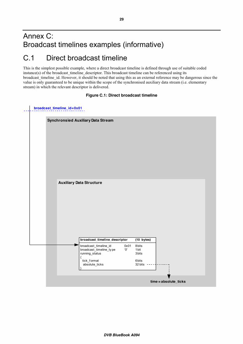
C.1 Direct broadcast timeline This is the simplest possible example, where a direct broadcast timeline is defined through use of suitable coded instance(s) of the broadcast_timeline_descriptor. This broadcast timeline can be referenced using its broadcast_timeline_id. However, it should be noted that using this as an external reference may be dangerous since the value is only guaranteed to be unique within the scope of the synchronised auxiliary data stream (i.e. elementary stream) in which the relevant descriptor is delivered.
Figure C.1: Direct broadcast timeline
Synchronsied Auxiliary Data Stream
Auxiliary Data Structure
broadcast_timeline_descriptor (10 bytes)
broadcast_timeline_id 0x01 8 bitsbroadcast_timeline_ty pe ‘0' 1 bitrunning_status 3 bits{ tick_f ormat 6 bits absolute_ticks 32 bits}
time = absolute_ticks
broadcast_timeline_id = 0x01

DVB BlueBook A094
30
C.2 Offset broadcast timeline This is a slightly more complex example, where an offset broadcast timeline is defined by reference to a direct broadcast timeline. As with the exmple in Annex C.1, this broadcast timeline can be referenced using its broadcast_timeline_id. However, again it should be noted that using this as an external reference may be dangerous since the value is only guaranteed to be unique within the scope of the synchronised auxiliary data stream (i.e. elementary stream) in which the relevant descriptors are delivered.
Figure C.2: Offset broadcast timeline
It is also possible for more than one offset broadcast timeline to be defined with reference to the same direct broadcast timeline.
Synchronsied Auxiliary Data Stream
Auxiliary Data Structure
broadcast_timeline_descriptor (10 bytes)
broadcast_timeline_id 0x01 8 bitsbroadcast_timeline_ty pe ‘0' 1 bitrunning_status 3 bits{ tick_f ormat 6 bits absolute_ticks 32 bits}
broadcast_timeline_id = 0x02
broadcast_timeline_descriptor (10 bytes)
broadcast_timeline_id 0x02 8 bitsbroadcast_timeline_ty pe ‘1' 1 bitrunning_status 3 bits{ direct_broadcast_timeline_id 0x01 8 bits of f set_ticks 32 bits}
time = absolute_ticks + offset_ticks

DVB BlueBook A094
31
C.3 Implicit linking of a single broadcast timeline to an item of content
As described in the previous examples, the use of the broadcast_timeline_id as an external reference may not be reliable. Instead it will often be better to use a content identifier that has (ideally) a global scope. The linking from such a content identifier to a broadcast timeline can be achieved using the content_labeling_descriptor. In the following example a single (direct) broadcast timeline is implicitly associated with the item of content through appropriate coding of a content_labeling_descriptor. It would be just as valid to use the content_labeling_descriptor in this way to create an association with a single offset broadcast timeline.
Figure C.3: Implicit linking of broadcast timeline to an item of content
An example of a content identifier would be the TV-Anytime CRID.
Synchronsied Auxiliary Data Stream
Auxiliary Data Structure
Auxiliary Data Structure
broadcast_timeline_descriptor (10 bytes)
broadcast_timeline_id 0x01 8 bitsbroadcast_timeline_ty pe ‘0' 1 bitrunning_status 3 bits{ tick_f ormat 6 bits absolute_ticks 32 bits}
time = absolute_ticks
content_labeling_descriptor (9+N bytes)
metadata_application_f ormat 16 bitscontent_time_base_indicator 0x8 4 bitscontent_ref erencing_id “/my id” N by testime_base_mapping_f lag ‘0’ 1 bit{ timeline_id 0x01 8 bits}
broadcast_timeline_id
content_referencing_id = "/myid"
DVB BlueBook A094
32
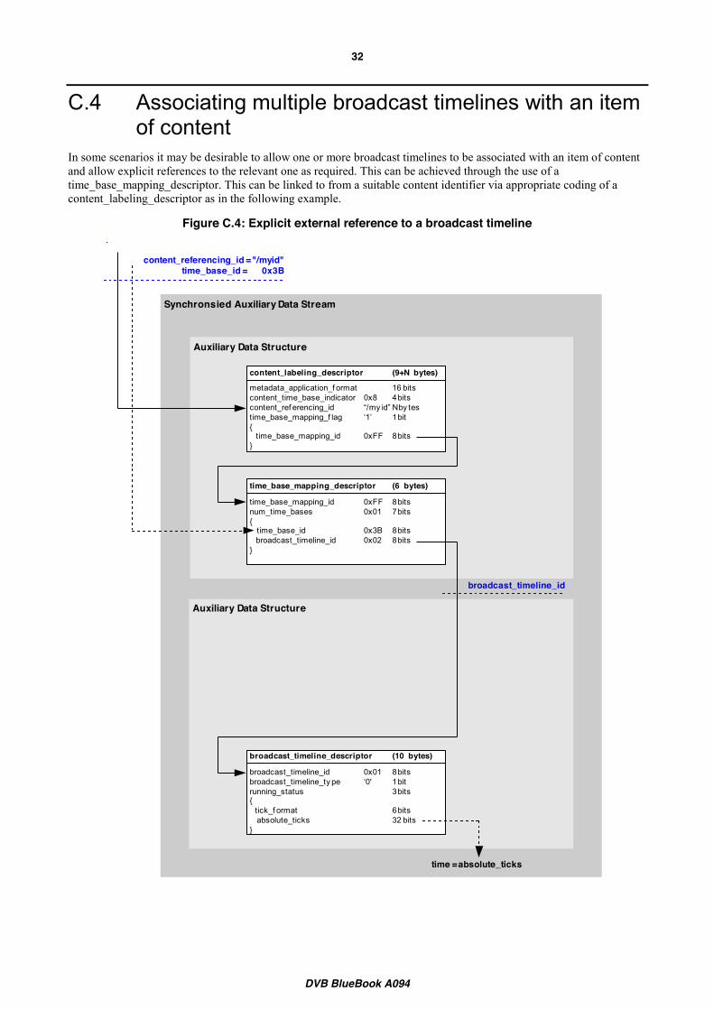
C.4 Associating multiple broadcast timelines with an item of content
In some scenarios it may be desirable to allow one or more broadcast timelines to be associated with an item of content and allow explicit references to the relevant one as required. This can be achieved through the use of a time_base_mapping_descriptor. This can be linked to from a suitable content identifier via appropriate coding of a content_labeling_descriptor as in the following example.
Figure C.4: Explicit external reference to a broadcast timeline
Synchronsied Auxiliary Data Stream
Auxiliary Data Structure
Auxiliary Data Structure
broadcast_timeline_descriptor (10 bytes)
broadcast_timeline_id 0x01 8 bitsbroadcast_timeline_ty pe ‘0' 1 bitrunning_status 3 bits{ tick_f ormat 6 bits absolute_ticks 32 bits}
time = absolute_ticks
content_labeling_descriptor (9+N bytes)
broadcast_timeline_id
time_base_mapping_descriptor (6 bytes)
time_base_mapping_id 0xFF 8 bitsnum_time_bases 0x01 7 bits{ time_base_id 0x3B 8 bits broadcast_timeline_id 0x02 8 bits}
metadata_application_f ormat 16 bitscontent_time_base_indicator 0x8 4 bitscontent_ref erencing_id “/my id” N by testime_base_mapping_f lag ‘1’ 1 bit{ time_base_mapping_id 0xFF 8 bits}
content_referencing_id = "/myid"time_base_id = 0x3B
DVB BlueBook A094
33
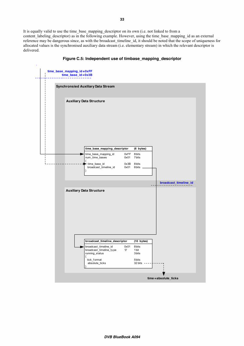
It is equally valid to use the time_base_mapping_descriptor on its own (i.e. not linked to from a content_labeling_descriptor) as in the following example. However, using the time_base_mapping_id as an external reference may be dangerous since, as with the broadcast_timeline_id, it should be noted that the scope of uniqueness for allocated values is the synchronised auxiliary data stream (i.e. elementary stream) in which the relevant descriptor is delivered.
Figure C.5: Independent use of timbase_mapping_descriptor
Synchronsied Auxiliary Data Stream
Auxiliary Data Structure
Auxiliary Data Structure
broadcast_timeline_descriptor (10 bytes)
broadcast_timeline_id 0x01 8 bitsbroadcast_timeline_ty pe ‘0' 1 bitrunning_status 3 bits{ tick_f ormat 5 bits absolute_ticks 32 bits}
time = absolute_ticks
time_base_mapping_descriptor (6 bytes)
time_base_mapping_id 0xFF 8 bitsnum_time_bases 0x01 7 bits{ time_base_id 0x3B 8 bits broadcast_timeline_id 0x01 8 bits}
broadcast_timeline_id
time_base_mapping_id = 0xFFtime_base_id = 0x3B
DVB BlueBook A094
34
Annex D: Broadcast timeline disruption in digital TV distribution systems (informative)
D.1 Introduction There are many reasons why the relationship between a broadcast timeline and the content to which it relates may be disrupted as they pass through digital TV distribution systems. One instance of this is insertion of new content such as adverts or trailers at a point between the originator of the content and the digital TV receiver.
Mechanisms by which insertion may be accomplished include the following:
1. The insertion completely replaces all elementary streams of the original content (including any original timeline) and this data is essentially discarded. E.g. a real-time feed from a network being replaced with local advertisements.
2. The insertion completely replaces all elementary streams of the original content (including any original timeline) but this data is not lost. When the insertion is completed, the original content resumes at the point of interruption without any loss. E.g. a non real-time distribution system where the original content is paused for the duration of the insertion.
3. The insertion replaces only the video and audio elementary streams of the original content and this data is essentially discarded. However, other elementary streams (including any original timeline) are passed through without modification. E.g. a real-time feed from a network being replaced with local advertisements.
Regardless of the insertion mechanism used it is possible that the point where the insertion occurs is either anticipated, where the nature and timing of the insertion is known in advance, or unanticipated, where the original content is unexpectedly interrupted.
This Annex describes the two scenarios in more detail and recommends how such insertions should be executed by the broadcaster and managed by the receiver.
D.2 Anticipated content insertion In this case, the temporal location for the insertion will have been anticipated in the original content. This case presents no significant challenges for the provision of a broadcast timeline and any associated events. Suitable techniques include the following:
x pausing the broadcast timeline for the duration of the insertion
x running the broadcast timeline (or timelines as described in Annex B) continuously through the insertion while ensuring that the values of time in this period are not used, either by metadata referencing the content or by scheduled events
The insertion of the new content could be performed before or after MPEG encoding. In addition, the component carrying the broadcast timeline could be removed from the service during the insertion. However, if the timeline is to be paused (through use of the running_status field) it is important that any removal occurs only after the pause has been signalled. Similarly, to allow receivers to recreate the timeline accurately following the end of the insertion, the timeline component needs to be returned prior to the timeline being resumed.
Where a timeline has been paused or removed, it is recommended that the prev_discontinuity_ticks field be encoded in the broadcast_timeline_descriptor for a period following the resumption of the timeline.
DVB BlueBook A094
35
D.3 Unanticipated content insertion In this scenario, the timeline for the original content will never be paused (through use of the running_status field) because by definition the timing of the insertion is not known at the point of timeline generation.
Where the insertion mechanism is simply to replace (and discard) the original content the original timeline will effectively continue to advance during any downstream insertion.
Where the insertion mechanism is to pause the playout of the original content the state of the original timeline will be somewhat ambiguous: ideally its running_status should be “paused” but as stated above this will not occur.
In both cases the result is that during the insertion it may be unreliable, and so undesirable, for receivers to attempt to track the original timeline (and possibly fire any associated events).
It is therefore recommended that for this scenario, the elementary stream carrying the broadcast timeline be removed from the PMT during the insertion. Although the detection of this removal can never be frame accurate, this provides a positive removal event that can be detected quickly by the receiver. Broadcasters will need to consider the trade off between premature removal of the timeline and the possibility of timeline related events and actions occurring after the start of the insertion
Following the return of the timeline component in the PMT, a receiver can only recreate an accurate timeline once the first broadcast_timeline_descriptor has been received.
D.4 Recommendations for insertion To summarise, when content is being inserted at locations not anticipated in the original content, the following recommendations apply:
x Where it is not possible or appropriate to pause the broadcast timeline during the insertion, the component carrying the timeline should be removed from the PMT.
x If the new inserted content also has a timeline, some co-ordination is required to agree partitioning of relevant name- and number-spaces to allow independent allocation without risk of clash. The precise manner in which the change should be signalled will be application-specific. For example, where the timeline is referenced using a content_labelling_descriptor, this descriptor could be changed to reference an alternative timeline during the insertion; where the timeline is referenced from a DSM-CC carousel, the timeline component could be replaced by another using a different component tag.
D.5 Recommendations for receivers To ensure reliable usage of timelines in the presence of downstream content insertion, receivers will continually monitor the PMT of the relevant service. Timeline information is only valid whilst the elementary stream in which the relevant broadcast_timeline_descriptors are delivered remains present.
Where a timeline has been located via a content_labelling_descriptor, this descriptor should also be monitored for changes.
When a new timeline component is added to a service, receivers should consider the timeline undefined until the first broadcast_timeline_descriptor is received, regardless of whether or not the component has been present previously. With recorded content, a receiver may be able to extrapolate a timeline back to the end of the discontinuity depending on the information in the first received descriptor.
NOTE: All of the above applies only where the receiver can positively confirm that a timeline has been removed. Temporary loss of timeline descriptors due to reception errors or other corruption should be managed by interpolation, as described in clause 5.2.2 of the present document.
DVB BlueBook A094
36
History This clause shall be the last one in the document.
History box entries
Document history <Version> <Date> <Milestone>
A few examples:
Document history V1.1.1 April 2001 Publication
V1.1.1 February 2002 One-step Approval Procedure OAP XXXX: yyyy-mm-dd to yyyy-mm-dd
V1.1.1 June 2001 Pre-processed by the ETSI Secretariat editHelp! E-mail: mailto:[email protected]
2003-12-18