digital torque screwdriver tester model tdt3-g · conduct "safe operations and proper...
TRANSCRIPT

OPERATING INSTRUCTION
To use this product properly and safely, please read this manual carefully before use. If you have any question about the product and its operations, please contact your nearest distributor or TOHNICHI MFG. CO., LTD.
TDT3-G TDT3-G Model
MODEL TDT3-GDIGITAL TORQUE SCREWDRIVER TESTER

1
nDIGITA
L TORQUE SCREWDRIVER TE
STE
R M
ODEL TDT3-G
To customers: Before using this product, please read
this operating instruction carefully to use it properly.
If you have any question, please contact your nearest
distributor or TOHNICHI MFG. CO., LTD. This operating
instruction should be stored in a safe place.
(4) Do not connect or disconnect the power plug with
wet hands.
You may be exposed to the danger of electric shock.
(5) Do not use this tester with a power voltage other
than that specified (AC100V to 240V).
Use with any unspecified power voltage may result in
electric shock or fire.
(6) Do not use a damaged power cable.
Use of a damaged power cable may result in electric
shock or fire.
When handling the power cable, fol low the
instructions below.
• Do not damage, extend or heat the power cable.
• Do not yank the power cable, put heavy objects on
it, or pinch it.
• Do not bend the power cable by force, twist it or
bind it.
• Do not use a power cable other than that supplied
with the product.
• Do not use the power cable with other devices.
(7) Handle the power plug carefully.
Improper handling may result in fire.
• Remove any foreign matter such as dust before
inserting the plug into outlet.
• Be sure to insert the power plug fully into outlet.
(8) When removing the power plug from outlet, grasp
the plug by hand.
Do not pull on the power cable. It may damage the
cable, resulting in fire or electric shock.
(9) Do not place this tester on an unstable or shaky
place such as a rickety table or slope.
The tester may fall, resulting in injury.
(10) Do not put this tester in a place where inflammable
liquid or combustible gas is present.
It may cause electric shock or fire.
(11) Be sure to use the specified accessories or options.
Do not use any accessory or option other than those
specified in this operating instruction.
Use of any unspecified accessory may result in
accident or injury.
Safety Precautions
Safety Symbol
This symbol is used for drawing attention to "safety
precautions". If you see this symbol in this operating
instruction, attention should be paid to safety. Take
preventative actions according to the description and
conduct "safe operations and proper control".
Signal Words
The signal words are the headers which indicate the level
of hazard that should be known for human safety in
handling devices. The signal words for safety are
"Danger", "Warning" and "Caution" depending on the
level of hazard to human. The signal words are used with
the safety symbol to indicate the following situations.
" Danger": Indicates an imminently hazardous situation which,
if not avoided, will result in death or serious injury.
" Warning": Indicates a potentially hazardous situation which, if
not avoided, could result in death or serious injury.
" Caution": Indicates a potentially hazardous situation which, if
not avoided, may result in minor or moderate injury.
Warning(1) Stop using the product when smoke comes out or
strange smell or unusual noise occurs.
Use in an abnormal state may result in electric shock
or fire.
Immediately turn off the power, remove the plug from
the outlet and contact your nearest distributor or
TOHNICHI MFG. CO., LTD.
(2) Do not disassemble or modify this tester.
It may result in loss of safety, degradation in
functions, shortening of product life, or failure.
(3) Stop using the product when foreign matter or liquid
such as water gets inside.
If not, you may be exposed to the danger of electric
shock or fire.

2
nDIGITA
L TORQUE SCREWDRIVER TE
STE
R M
ODEL TDT3-G
(1) Do not put this tester in a place of much moisture or
dust, in a place that is exposed to water or direct
sunlight, or in a place where the humidity or
temperature fluctuates largely.
It may result in electric shock, fire, malfunction,
degradation of performance or failure.
(2) Clean the power plug periodically. Before cleaning,
disconnect the plug from outlet and clean the root of
the plug and the portion between the blades.
Accumulation of dust at the root of the power plug
may cause a short circuit, leading to fire.
(3) If this tester is not to be used for a long time, be sure
to disconnect the power plug from outlet for safety's
sake.
(4) Before moving this tester to another place, be sure to
turn off the power, remove the power plug from
outlet and disconnect all connecting cables. When
moving the tester, avoid shock or vibration to it.
It may damage the power cable or connecting
cables, resulting in fire, electric shock or malfunction.
(5) Do not use this tester to conduct measurements
beyond its capacity.
For safe and efficient operation, use this tester to
measure the torque wrenches suited to the capacity.
Measurement beyond the capacity may cause
accident or damage.
(6) Check for any damaged parts.
Before use, check the tester, accessories and other
parts for damage and make sure that it operates
normally and fulfills the specified functions.
Check the parts and all other portions that may affect
the operation for damage, installation status, etc.
For replacement or repair of damaged parts, contact
your nearest distributor or TOHNICHI MFG. CO.,
LTD.
Caution
For proper and safety use
(1) Source voltage is limited to AC100-240V ±10% range
and it cannot be used beyond this range.
(2) Make sure to use the accompanying AC adapter only.
(3) Do not apply vibration or physical impact on this tester.
(4) Do not use this tester in conditions not specified in
this operating instruction.
(5) Check the functions and settings before use.
(6) Be careful not to expose the product to water or oil
as it may cause malfunction.
(7) Do not drop the product or hit it against other objects
as it may cause product failures.
(8) Do not use the product beyond its capacity specified
in this operating instructions.
(9) This tester is designed to use for torque screwdrivers
only. Do not use it for measuring other products.
(10) Make sure to conduct periodic inspection.
(11) Make sure to conduct zero adjustment before
measuring.
If there should be strange smell or fire on usage,
immediately stop using. Move this instrument to a safe
place and contact TOHNICHI.
Precautions for Use

3
nDIGITA
L TORQUE SCREWDRIVER TE
STE
R M
ODEL TDT3-G
Safety Precautions ............................................................... 1
1. Features.......................................................................... 4
2. Components................................................................... 5
3. Specifications................................................................. 6
4. Names of Parts............................................................... 84-1. Indicator and Operating Parts ................................. 84-2. Power Source and Output ..................................... 9
5. Functions and Operation ...............................................105-1. Run Mode...............................................................105-2. Peak Hold Mode.....................................................105-3. Selecting Upper and Lower Limit Value ...................105-4. OK/NG Judgment/Data Memory.............................105-5. Auto Memory/Reset................................................105-6. Deletion of Data ......................................................115-7. Statistical Processing Function................................115-8. Auto Zero Adjustment .............................................115-9. Over-Torque Alarm..................................................125-10. Error Display ...........................................................12
6. Various Settings ............................................................13
7. Measuring a Torque Screwdriver (Recommended) ......18
8. External Output ..............................................................218-1. Printer Output .........................................................218-2. PC Output ..............................................................23
9. Optional Accessories .....................................................24
10. Calibration Procedure ....................................................25
Contents

4
nDIGITA
L TORQUE SCREWDRIVER TE
STE
R M
ODEL TDT3-G
TDT3-G torque screwdriver tester has the following features.
• Mechanical loading eliminates errors caused by varied factors such as operator’s measuring
speed or application force.
• Torque screwdriver will be firmly fixed by the loading device, which minimizes individual margin
of errors, especially when calibrating direct-reading torque screwdrivers.
• Up to 1000 pc of data can be stored. The number of samples, maximum value, minimum
value or mean value of the stored data can be calculated and displayed.
• Judgment function allows users to register upper/lower limit torque value, and have TDT3-G
give judgment on the measured value against the registered torque range. Blue light is lit when
OK, and red light is lit when the value is out of the registered range.
10 different kinds of upper limit value and lower limit value can be registered.
• RS232C (compliant) connector and USB connector (B type) are equipped as standard. They
can be easily connected to PC and TOHNICHI printer.
• This tester has CE marking and can be used in EU without problem.
1 Features

TDT3-G tester and accessories
5
nDIGITA
L TORQUE SCREWDRIVER TE
STE
R M
ODEL TDT3-G
2 Components
· TDT3-G main body
· STA loading device
· Standard clamp block
· Fixing knob · Clamp tool
· Standard bit · bit S
· AC adapter (BA-6)
· Power connector conversion adapter (C type)
· Operating instruction
· Operation sticker
* When purchasing, TDT3-G package includes STA loading device, fixing knob, standard clamp
block, and standard bit.
When measuring direct reading torque screwdrivers, use LTA loading device (optional).

6
nDIGITA
L TORQUE SCREWDRIVER TE
STE
R M
ODEL TDT3-G
3 Specifications
Model TDT60CN3-G TDT600CN3-G
Newton Min. to Max. 2 to 60 20 to 600
[cN·m] 0.005 (0.01) 0.05 (0.1)
Metric Min. to Max. 0.2 to 6 2 to 60
Torque [kgf·cm] 0.0005 (0.001) 0.005 (0.01)
Range American Min. to Max. 3 to 80 30 to 800
[ozf·in] 0.005 (0.01) 0.05 (0.1)
American Min. to Max. 0.2 to 5 2 to 50
[lbf·in] 0.0005 (0.001) 0.005 (0.01)
Measuring Direction CW/CCW
Accuracy ±1% + 1digit
Data Memory 1000 (99 in M99 mode)
Measuring Mode PEAK/RUN
Statistical Processing Number of samples/max./min./mean value
Upper/Lower Limit Value Setting 10 kinds
Zero Adjustment Auto
Reset Manual/Auto (0.1-5.0 sec. selectable)
Data Output RS232C (compliant), USB (B type) serial communication
Square Drive Hex 6.35 (male) minus 0.7mm (with groove)
Operating Temperature 0-40 degree (without condensation)
Power AC100-240V 50/60Hz
Weight Approx. 11kg
STA (LTD/RTD loading device)Applicable grip diameter ø7-50mm
LTA (loading device for FTD)
LTD/RTD 15, 30, 60CN (60), 120, 260, 500CN
Loading NTD/RNTD 15, 30, 60CN (60), 120, 260, 500CN
AMLD (4), 8CNDevice FTD
BMLD 15, 30CNModels
RTDZ/RNTDZ 260, 500CN
Loading FTD 50CN (50), 100, 200, 400CN
Device LTA FTD2-S (5), 10, 20, 50CN (50), 100, 200, 400CN(option) STC 50CN (50), 200, 400CN
1 digit(in M99 mode)
1 digit(in M99 mode)
1 digit(in M99 mode)
1 digit(in M99 mode)
7
nDIGITA
L TORQUE SCREWDRIVER TE
STE
R M
ODEL TDT3-G
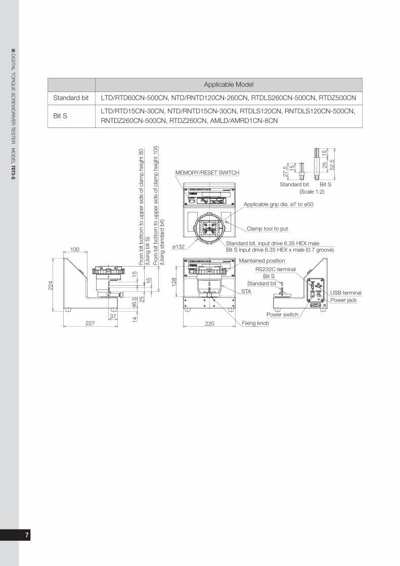
Applicable Model
Standard bit LTD/RTD60CN-500CN, NTD/RNTD120CN-260CN, RTDLS260CN-500CN, RTDZ500CN
Bit SLTD/RTD15CN-30CN, NTD/RNTD15CN-30CN, RTDLS120CN, RNTDLS120CN-500CN,RNTDZ260CN-500CN, RTDZ260CN, AMLD/AMRD1CN-8CN
100
From
bit
bott
om to
upp
er s
ide
of c
lam
p he
ight
80
(Usi
ng b
it S
)Fr
om b
it bo
ttom
to u
pper
sid
e of
cla
mp
heig
ht 1
05(U
sing
sta
ndar
d bi
t)
MEMORY/RESET SWITCH
Applicable grip dia. ø7 to ø50
Clamp tool to put
Standard bit, input drive 6.35 HEX maleBit S input drive 6.35 HEX x male (0.7 groove)ø132
Maintained position
STAStandard bit
Bit SRS232C terminal
Fixing knob
Power switch
Power jackUSB terminal
Bit SStandard bit(Scale 1:2)
1527
.5 25 52.5
15
15
1525
46.5
14
128
224
22737
220
8
nDIGITA
L TORQUE SCREWDRIVER TE
STE
R M
ODEL TDT3-G
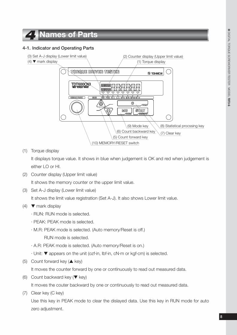
4-1. Indicator and Operating Parts
4 Names of Parts
(3) Set A-J display (Lower limit value) (2) Counter display (Upper limit value)(1) Torque display
(9) Mode key
(7) Clear key
(8) Statistical procssing key
(6) Count backward key
(5) Count forward key
(10) MEMORY/RESET switch
(4) ▼ mark display
(1) Torque display
It displays torque value. It shows in blue when judgement is OK and red when judgement is
either LO or HI.
(2) Counter display (Upper limit value)
It shows the memory counter or the upper limit value.
(3) Set A-J display (Lower limit value)
It shows the limit value registration (Set A-J). It also shows Lower limit value.
(4) t mark display
· RUN: RUN mode is selected.
· PEAK: PEAK mode is selected.
· M.R: PEAK mode is selected. (Auto memory/Reset is off.)
RUN mode is selected.
· A.R: PEAK mode is selected. (Auto memory/Reset is on.)
· Unit: t appears on the unit (ozf·in, lbf·in, cN·m or kgf·cm) is selected.
(5) Count forward key (s key)
It moves the counter forward by one or continuously to read out measured data.
(6) Count backward key (t key)
It moves the couter backward by one or continuously to read out measured data.
(7) Clear key (C key)
Use this key in PEAK mode to clear the dislayed data. Use this key in RUN mode for auto
zero adjustment.

9
nDIGITA
L TORQUE SCREWDRIVER TE
STE
R M
ODEL TDT3-G
(8) Statistical processing key (STAT key)
Use this key to select samples, maximum value, minimum value or average value.
(9) Mode Key (MD key)
Push this key to select RUN mode or PEAK mode.
Keep pushing this key for 2 seconds or more, then it turns to uper/lower limit value selection.
(10) MEMORY/RESET switch
After giving judgement to the measured data, it moves the counter forward by one.
4-2. Power Source and Output
USB terminal
RS232C terminal
Power jack
Power switch
(1) Power jack (12V, 1A, center plus)
Use the included AC adapter (BA-6).
(2) Power switch
Turn power ON and OFF.
(3) RS232C terminal
Use RS232C communication cable to connect.
(4) USB terminal (B type), serial terminal
Connect USB communication cable.
* RS232C terminal and USB terminal should not be connected to external device at the same time.

10
nDIGITA
L TORQUE SCREWDRIVER TE
STE
R M
ODEL TDT3-G
5-1. RUN MODE
Torque value increases as torque is applied, and decreases and returns to 0 as it is released.
t mark appears above RUN. This mode is used when measuring a direct-reading torque
screwdriver or calibrating TDT3-G itself. Push MD key to switch to PEAK MODE.
5-2. PEAK HOLD MODE
Torque value increases as torque is applied, and the displayed value stays at the peak value
after releasing load. t mark appears above PEAK on the display panel. This mode is used
mainly for measuring click-type torque screwdrivers. Push MD key to switch to RUN MODE.
5-3. Selecting Upper and Lower Limit Value
Select pre-registered upper/lower limit value.
(1) Keep pushing MD key for 2 seconds and the display proceeds to upper/lower limit selection.
(2) Using st key, select upper and lower limit value.
(3) Push STAT key to decide upper/lower limit value and returns to measuring condition. If you
push MD key, it returns to measuring condition with previous upper/lower limit value settings.
(For setting upper/lower limit value, refer to chapter 6 Various Settings.)
5-4. OK/NG Judgment/Data Memory
As MEMORY/RESET button is pushed (or AUTO MEMORY/RESET function operates),
judgment will be conducted, and measured data will be saved up to 1000pc. When judgment is
OK, the digital display turns blue for 0.5 seconds. When judgment is LO/HI, the digital display
turns red for 1 second. Judgment will not be conducted when upper/lower limit value is set to
0. Judgment will be conducted with the following conditions.
HI: Upper limit value < Measured value
OK: Lower limit value ≤ Measured value ≤ Upper limit value
LO: Measured value < Lower limit value
5-5. Auto Memory/Reset
In Auto Memory/Reset function, judgment will be conducted 0.1-5.0 seconds after releasing load
(PEAK HOLD) and the measured value is saved automatically. The display proceeds to the next counter.
When the judgment is OK, the digital display turns blue for 0.5 seconds. When the judgment is
LO/HI, the digital display turns red for 1 second. When upper/lower limit value is set to 0,
judgment will not be conducted.
5 Functions and Operation
11
nDIGITA
L TORQUE SCREWDRIVER TE
STE
R M
ODEL TDT3-G
5-6. Deletion of Data
(1) Delete one data
Select the data you want to delete by using st key. Push C key to delete the data.
(2) Delete a range of data
Select the last counter of the data range you want to delete by using st key. Push STAT
key, the “Stt” appears on the display. Then select the first counter of the data range you want
to delete by using st key and push STAT key again. While the display shows “n”, “HI”, “Lo”
or “Av”, push STAT key and C key at the same time to delete the selected range of data.
(3) Delete all data
While pushing MEMORY/RESET switch, turn on the power. “CLEAr” appears on the display
and all the data will be deleted.
Attention
* Before deleting data, check again if the data is really OK to delete.
* Before turning the power off, make sure to transfer all the necessary data to an external device.
5-7. Statistical Processing Function (Number of sample, Max, Minimum, Mean value)
(1) Using st key, select the last counter of the data range you want to calculate.
(2) Push STAT key, then “Stt” appears on the display. Using st key, select the first counter of
your selected data range.
Push STAT key, then it shows the number of sample “n”, maximum value “HI”, lowest value
“Lo”, and the mean value “Av” in order.
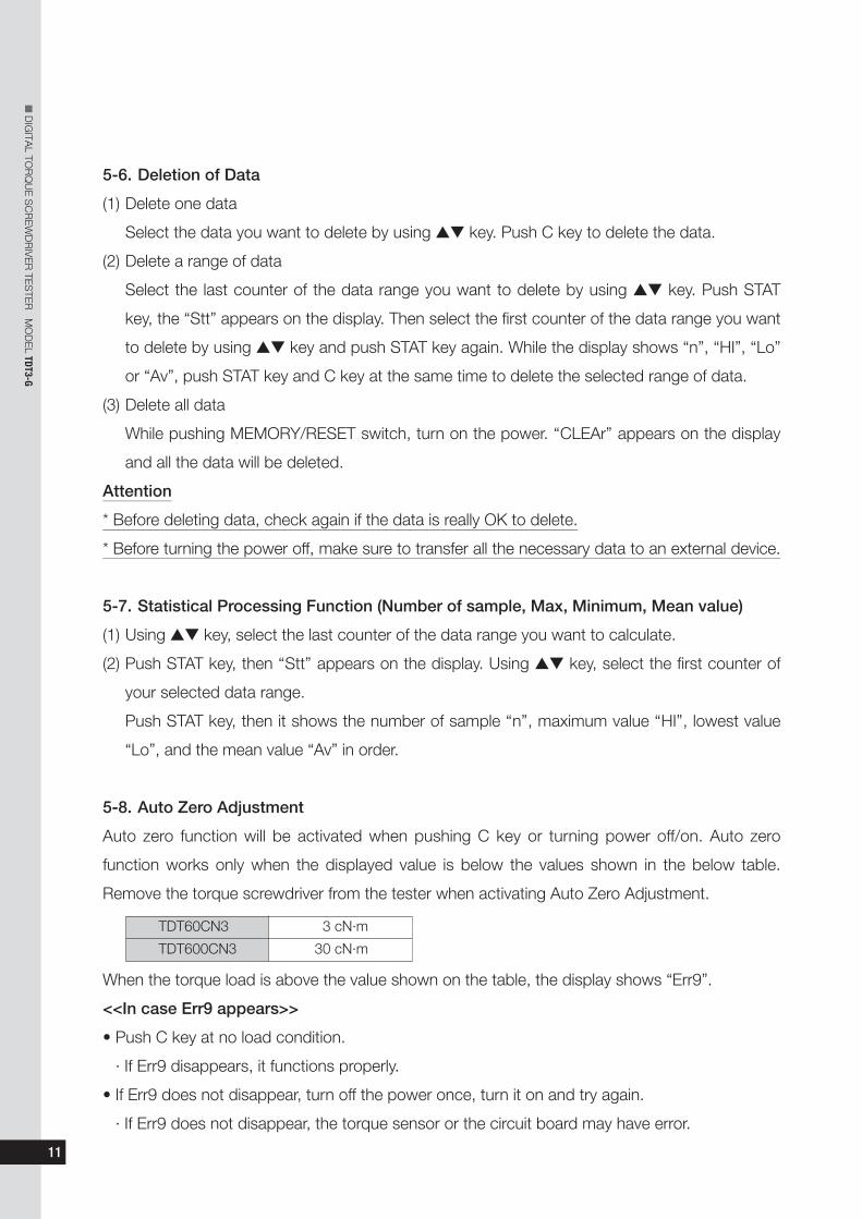
5-8. Auto Zero Adjustment
Auto zero function will be activated when pushing C key or turning power off/on. Auto zero
function works only when the displayed value is below the values shown in the below table.
Remove the torque screwdriver from the tester when activating Auto Zero Adjustment.
When the torque load is above the value shown on the table, the display shows “Err9”.
<<In case Err9 appears>>
• Push C key at no load condition.
· If Err9 disappears, it functions properly.
• If Err9 does not disappear, turn off the power once, turn it on and try again.
· If Err9 does not disappear, the torque sensor or the circuit board may have error.
TDT60CN3 3 cN·m
TDT600CN3 30 cN·m

12
nDIGITA
L TORQUE SCREWDRIVER TE
STE
R M
ODEL TDT3-G
5-9. Over-Torque Alarm
If applied torque exceeds 110% of the maximum limit of the measurable torque range, the value
on the display flashes for alarming.
5-10. Error Display
TDT3-G includes self-check function, and Err1-9 will be displayed when there is an error.
<<when Err1-5 appears>>
• Turn off the power, and turn it on without touching any keys.
· If Err disappears, it is restored.
· If Err continues to stay, contact your nearest distributor or TOHNICHI to seek assistance.
<<when Err8 appears>>
• Contact your nearest distributor or TOHNICHI for repair.
<<when Err9 appears>>
• Push C key at no load condition.
· If Err9 disappears, it is restored.
• If Err9 continues to stay, turn off the power once and turn it on again.
· If Err9 still continues to stay, contact your nearest distributor or TOHNICHI for repair.
13
nDIGITA
L TORQUE SCREWDRIVER TE
STE
R M
ODEL TDT3-G
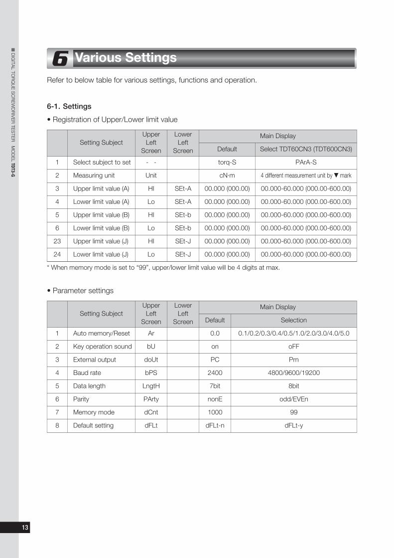
Refer to below table for various settings, functions and operation.
6-1. Settings
• Registration of Upper/Lower limit value
6 Various Settings
Setting SubjectMain Display
Default Select TDT60CN3 (TDT600CN3)
1 Select subject to set - - torq-S PArA-S
2 Measuring unit Unit cN·m 4 different measurement unit by t mark
3 Upper limit value (A) HI SEt-A 00.000 (000.00) 00.000-60.000 (000.00-600.00)
4 Lower limit value (A) Lo SEt-A 00.000 (000.00) 00.000-60.000 (000.00-600.00)
5 Upper limit value (B) HI SEt-b 00.000 (000.00) 00.000-60.000 (000.00-600.00)
6 Lower limit value (B) Lo SEt-b 00.000 (000.00) 00.000-60.000 (000.00-600.00)
23 Upper limit value (J) HI SEt-J 00.000 (000.00) 00.000-60.000 (000.00-600.00)
24 Lower limit value (J) Lo SEt-J 00.000 (000.00) 00.000-60.000 (000.00-600.00)
* When memory mode is set to “99”, upper/lower limit value will be 4 digits at max.
UpperLeft
Screen
LowerLeft
Screen
• Parameter settings
Setting SubjectMain Display
Default Selection
1 Auto memory/Reset Ar 0.0 0.1/0.2/0.3/0.4/0.5/1.0/2.0/3.0/4.0/5.0
2 Key operation sound bU on oFF
3 External output doUt PC Prn
4 Baud rate bPS 2400 4800/9600/19200
5 Data length LngtH 7bit 8bit
6 Parity PArty nonE odd/EVEn
7 Memory mode dCnt 1000 99
8 Default setting dFLt dFLt-n dFLt-y
UpperLeft
Screen
LowerLeft
Screen

14
nDIGITA
L TORQUE DRIVER TE
STE
R M
ODEL TDT2-G
6-2. Registration of Upper/Lower Limit Value
• Changing to setting mode
At no load condition, push C => STAT => MD key in order, then the screen shows item selection
after “----”.
• Selecting items to set
Register upper/lower limit value and other parameter settings.
While it shows “torq-S”, press MD key or STAT key then it proceeds to next.
(If you press C key, it returns to measuring display without setting.)
• Selecting measuring unit (default: cN·m)
Select measuring unit.
Use st key to select unit and push STAT key to decide.
(If you press C key, it returns to measuring display without setting.)
• Registering upper limit value (A) (default: 0)
Register upper limit value (A) for judgment.
Use s key to select digit, and t key to select number, and STAT key to decide and proceed to
lower limit value (A) setting.
(If you push MD key, it proceeds to next without saving. If you push C key, it returns to
measuring display. If the input value is out of the measurable range, it shows “SEtErr” and
automatically returns to upper limit value setting.)

• Register lower limit value (A) (default: 0)
Register lower limit value (A) for judgment.
Use s key to select digit, t key to select number, and STAT key to decide and proceed to
upper limit (B) setting.
(If you push MD key, it proceeds to next without saving. If you push C key, it returns to
measuring display. If the input value is out of the measurable range, it shows “SEtErr” and
automatically returns to upper limit value setting)
In the same way, register upper and lower limit value (B to J).
After registering the lower limit value (J), it returns to the measuring display.
If you want to cancel settings, push C key to return to the measuring display without setting.
6-3 Parameter Settings
• Setting mode
At no load condition, push C => STAT => MD key, then it turns to setting.
• Selecting items to set
Select upper/lower limit or parameter setting.
Use st key to change it to “PArA-S” and push MD key or STAT key to proceed to next.
(If you press C key, it returns to measuring display without setting.)
• Auto memory/Reset (default: 0.0)
Using st key, set the timing from 0.1 to 5.0 seconds and push STAT key to decide and
proceed to next.
To cancel Auto memory/Reset mode (manual mode), set it to 0.0.
(If you press C key, it returns to measuring display without setting.)
15
nDIGITA
L TORQUE SCREWDRIVER TE
STE
R M
ODEL TDT3-G
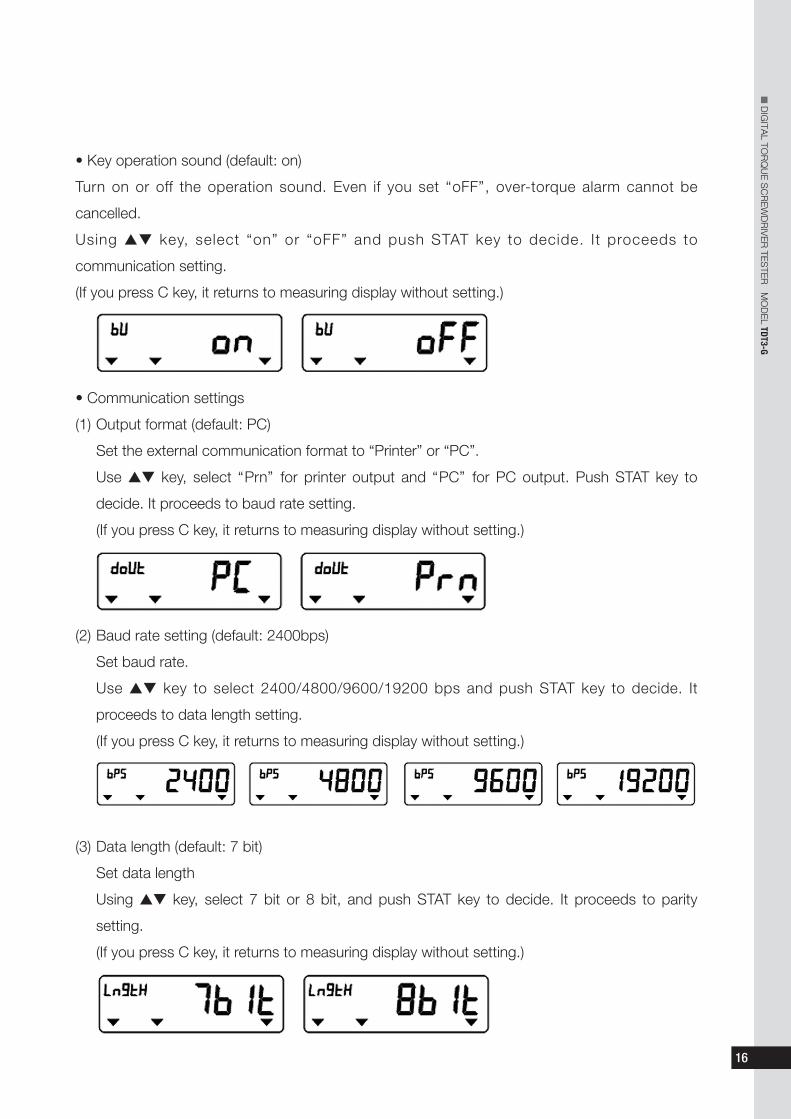
• Key operation sound (default: on)
Turn on or off the operation sound. Even if you set “oFF”, over-torque alarm cannot be
cancelled.
Using st key, select “on” or “oFF” and push STAT key to decide. It proceeds to
communication setting.
(If you press C key, it returns to measuring display without setting.)
• Communication settings
(1) Output format (default: PC)
Set the external communication format to “Printer” or “PC”.
Use st key, select “Prn” for printer output and “PC” for PC output. Push STAT key to
decide. It proceeds to baud rate setting.
(If you press C key, it returns to measuring display without setting.)
(2) Baud rate setting (default: 2400bps)
Set baud rate.
Use st key to select 2400/4800/9600/19200 bps and push STAT key to decide. It
proceeds to data length setting.
(If you press C key, it returns to measuring display without setting.)
(3) Data length (default: 7 bit)
Set data length
Using st key, select 7 bit or 8 bit, and push STAT key to decide. It proceeds to parity
setting.
(If you press C key, it returns to measuring display without setting.)
16
nDIGITA
L TORQUE SCREWDRIVER TE
STE
R M
ODEL TDT3-G

(4) Parity (default: none)
Set parity
Using st key, select “nonE” for none, “EVEn” for even, “odd” for odd and push STAT key to
decide. It returns to measuring condition.
(If you press C key, it returns to measuring display without setting.)
• Memory mode (default: 1000)
Select “1000” or “99” for number of data to store in memory. (1000: 1000pc of data can be
stored. 99: 99pc of data can be stored. Compliant with TDT2 communication format.
* If you select 99, torque value can be max 4 digit.
Using st key to select 1000 or 99, and push STAT to confirm.
(If you press C key, it returns to measuring display without setting.)
Push STAT key to switch memory mode, clear the memory data and proceed to next.
* By switching the memory mode, the measured data will be deleted.
(If you press C key, it returns to measuring display without setting.)
• Default setting
Put settings back to original setting (default setting).
Use st key and select “dFLt-Y” and push STAT key. All settings will be set back to original
setting (default setting).
(If you press C key, it returns to measuring display without setting.)
17
nDIGITA
L TORQUE SCREWDRIVER TE
STE
R M
ODEL TDT3-G

7-1-1. Operating Temperature
Measuring should be conducted at temperature in 18-28°C range. Temperature fluctuation
should be within ±1°C.
7-1-2. Check the Following before Calibrating the Torque Screwdriver.
(1) Torque screwdriver tester should be set at stable working table.
(2) For calibration of direct reading torque screwdriver, make sure to read the value from
upright position to avoid reading errors by angle.
(3) For calibration of click-type torque screwdriver (RTD/LTD), apply training torque at the
maximum value for 5 times without measuring prior to the official calibration. Do the same
training for the other direction as well.
(4) For calibration of direct reading torque screwdriver (FTD, STC), apply training torque to the
max torque value once and release the torque. Then set the digital display back to zero.
Repeat the same procedure for the other direction as well.
7-2. Attention for Measuring Torque Screwdrivers
(1) For measuring click-type torque screwdrivers (RTD/LTD), apply torque slowly and evenly.
Except for preset type (such as RNTD/NTD), click-type torque screwdrivers (such as
RTD/LTD) must measure from the lower point, and adjust to respective torque value.
(2) For measuring direct-reading type torque screwdriver (FTD/STC, etc), use torque
screwdriver tester to apply torque to the measurement value. If the applied torque exceed
the measurement point, it needs to be redone.
* LTA loading device is an optional kit.
18
7 Measuring a Torque Screwdriver (Recommended)
nDIGITA
L TORQUE SCREWDRIVER TE
STE
R M
ODEL TDT3-G

7-3. How to Measure
(1) Set TDT3-G on stable work table free of vibration.
(2) Connect AC adapter to the power jack on side of TDT3-G. Make sure the power is
switched off, then connect the adapter to power source.
(3) Turn on the power. (Leave it on for 30 minutes or more.)
(4) Conduct all settings.
Refer to Chapter 6 Various Settings for Auto memory/Reset and other communication settings.
(5) Set the measuring mode based on the torque screwdriver to measure.
Click type torque screwdriver (RTD/LTD): Peak mode (PEAK)
(6) Conduct auto zero adjustment.
Remove the torque screwdriver from the main body and push C to activate auto zero
adjustment.
(7) Set the bit according to the measuring model.
(See below table to see which bit suit your screwdriver.)
At purchase, TDT3-G package includes STA loading device and the standard bit.
For measuring direct-reading torque screwdriver, purchase LTA loading device (optional).
19
nDIGITA
L TORQUE SCREWDRIVER TE
STE
R M
ODEL TDT3-G
3. Insert the bit on TDT3-G mainbody and fix it by cap screw bolt.
2. Loosen cap screw bolt and remove the bit.
4. Set the loading device on TDT3-G and fix it by the fixing knob.
1. Loosen the fixing knob and remove the loading device.
Loading device
Fixing knob M4Cap screw bolt M3
Bit

(8) Check the measured value of the torque screwdriver.
(9) Put the torque screwdriver through the loading device and fix it by the clamp tool.
If the resin grip is on the screwdriver, remove it before setting.
20
nDIGITA
L TORQUE SCREWDRIVER TE
STE
R M
ODEL TDT3-G
If you hold other places than the loading center, accurate measurement cannot be done.
(11) Upon clicking of the torque screwdriver, release torque. In manual memory mode, push
MEMORY/RESET switch to save the data, then it resets.In auto memory/reset mode, it saves
data upon releasing the torque (2% of the max capacity), then send one counter and reset.
(12) Repeat (10) (11) process to measure.
Table STA loading device and bit selction
1. Put the torque screw driver through the loading device.
Torque screwdriver
Loading center(black)
Hold the external rim (black) of the loadingcenter and apply torque.
2. Use clamp tool to rotate the shaft to fix the torque screwdirver.
Shaft
Clamp tool(width-across-flat w=3mm)
Caution
To hold and fix the torque screwdriver
firmly, set it in such way that clamp block
and the surface of the screwdriver fit well.
BADGOOD
Clamp block Surface of torque screw driver.
(10) Apply torque by loading device until the
torque screwdriver clicks (operates).
Applicable Model
Standard bit LTD/RTD60CN-500CN, NTD/RNTD120CN-260CN, RTDLS260CN-500CN, RTDZ500CN
Bit SLTD/RTD15CN-30CN, NTD/RNTD15CN-30CN, RTDLS120CN, RNTDLS120CN-500CN,RNTDZ260CN-500CN, RTDZ260CN, AMLD/AMRD1CN-8CN

21
nDIGITA
L TORQUE SCREWDRIVER TE
STE
R M
ODEL TDT3-G
8-1. Printer Output
Connect TDT3-G and the printer (EPP16M2) using the cable (No. 382). Set the communication
output format to “Prn” and other communication settings compliant with printer settings (Refer to
chapter 6 for details.)
* Do not use the cable for printer and the USB cable at the same time.
• Communication settings of EPP16M2
Data format : Compliant with RS232C
Data transmission : Start-top synchronization
Baud rate : 2400bps
Data length : 7bit
Stop bit : 1bit
Parity : None
(1) Printing one by one
After measurement, press Memory/Reset key to print the measured data. In this mode, the
results of statistical processing are not printed. In Auto Memory/Reset mode, printing starts
automatically.
(2) Printing a certain range of data
Using s or t key, select the last count value in the print range and press STAT key, then “ST”
will be displayed. Using t or t key, select the first count value in the print range and press
STAT key. Then, press s key while “n” is displayed. The measured value, sampling quantity
“n”, maximum value “MAX”, minimum value “MIN” and mean value “x” of the selected range
will be printed out.
(3) Printing only statistical processing value
Using s or t key, display the last count value in the print range and press STAT key. Then,
“ST” will be displayed. Using s or t key, display the first count value in the print range and
press STAT key. Press t key while “n” is displayed. Only the sampling quantity “n”, maximum
value “MAX, minimum value “MIN” and average value “x” of the selected range will be printed
out.
8 External Output

22
nDIGITA
L TORQUE SCREWDRIVER TE
STE
R M
ODEL TDT3-G
• Continuous printing
In case of memory mode 1000
In case of memory mode
← Memory counter: judgement result, upper/lower← Limit value symbol, torque unit
← “--“ for no judgement”--”← Torque value =====
← Number of sample← Max value← Min value← Mean value
1:OK SET–A30.000cN・m21:HI SET–A31.000cN・m3:––==.===cN・m ・ ・ ・20:0K SET–A30.000 cN・m––––––––––––––n=18HI:31.OOOcN・mLO:29.OOOcN・mx :30.OOOcN・m
← Torque value unit
← Number of sample← Max value← Min value← Mean value
1:30.00cN・m 2 31.00cN・m 3:==.==cN・m ・ ・ ・20:30.00cN・m––––––––––––––n=18HI:31.OOcN・mLO:29.OOcN・mx :30.OOcN・m
“====” shows when the measured value is “0” or over 110%.

23
nDIGITA
L TORQUE SCREWDRIVER TE
STE
R M
ODEL TDT3-G
8-2. PC Output
Connect TDT3-G and external device by cable (No. 383 or No. 385).
Set the communication output format to “PC” and set it in line with other communication settings.
(Refer to Chapter 6 for details.)
* Do not use RS232C cable and USB cable at the same time.
* To use No. 385 cable, the screwdriver needs to be installed. Use the CD-R attached on No.
385 cable.
• Communication setting
Data format : RS232C compliant
Communication method : Asynchronous serial communication
Baud rate : 2400/4800/9600/19200bps
Data length : 7bit/8bit
Stop bit :1bit
Parity : None/Even/Odd
(1) Printing one by one
Push Memory/Reset switch or automatically print by Auto memory/Reset function.
(2) Printing all at one time
Set the last counter of the data range you wish to print out and push MD key. It shows “Stt”.
Use st key to select the first counter of the printing range and push MD key. When it shows
“n”, push STAT to start printing all data.
• PC output format
· In case of memory mode 1000
R E , 0 0 0 1 , 1 0 0 . 0 0 , A , O K CR LF
Torque value (inc. decimal point)
Judgement resultLO: “LO”OK: “OK”HI: “HI”no judgement: “– –”
DirectionCW: blankCCW: “–”
Upper/lower limitregistration letter“A” to “J”
DelimiterMemory counterHeader
· In case of memory mode 99 (TDT3-G compliant)
R E , 0 1 , 1 0 0 . 3 CR LF
Torque value (inc. decimal point)
DelimiterMemory counterHeader

24
nDIGITA
L TORQUE SCREWDRIVER TE
STE
R M
ODEL TDT3-G
Optional Accessories
(1) Printer ........................................................EPP16M2
(2) Cable for printer..........................................No. 382
(3) Cable for PC
TDT3-G -> PC (D-SUB9 Pin connector)......No. 383
TDT3-G -> PC (USB B type) .......................No. 385
(4) Calibration device
TDTCL60CN (Applicable model TDT60CN3-G)
TDTCL600CN (Applicable model TDT600CN3-G)
(5) Loading device for FTD ..............................LTA
(6) Loading device for torque wrench...............TDTLA3
Error list
9
ErrorMessage
Meaning Measures to Take
Err1-5 Switch is kept being Turn off the power. Turn it on without touching any key. If the error is pushed. cancelled, it can be used. If it still shows the error, contact your nearest
distributor or TOHNICHI.
Err8 CPU/memory problem Contact your nearest distributor or TOHNICHI for repair.
Err9 Torque sensor/internal Push C key at no load condition. If the error is cancelled, it can be used. circuit problem If not, the sensor or the internal circuit has problems. Contact your nearest
distributor or TOHNICHI for repair.

25
nDIGITA
L TORQUE SCREWDRIVER TE
STE
R M
ODEL TDT3-G
Calibration Procedure
(1) Precautions for use
1) Be careful not to drop weights on your foot.
2) Place a weight gently.
3) Start calibration at the minimum value.
4) Before calibration, secure the main unit in fixed position to prevent it from moving during
calibration.
5) Hook wire on the calibration lever securely.
(2) Calibration procedure
1) Place TDT3-G on the measurement table in a horizontal position.
2) Turn on the power of TDT3-G. (After the power is turned on, leave the unit as it is for 30
minutes or more for stabilization.)
3) Set TDT3-G in RUN mode.
4) Insert the square drive of the calibration lever into the TDT3-G sensor portion so that the
calibration lever is leveled.
5) Hook the wire on the calibration lever, and press "C" key on TDT3-G to make zero
adjustment.
6) Refer to the table on next page (Weights Information for TDT3-G Calibration), and check
the weight. Place weight on the TDT3-G accordingly, and proceed calibration.
10
Calibration roller
TDT3-G main unit
Calibration wire
Position of calibration roller for TDT60CN3-G
Position of calibration roller for TDT600CN3-G
Calibration lever for TDT60CN3-G
Calibration lever for TDT600CN3-G

26
nDIGITA
L TORQUE SCREWDRIVER TE
STE
R M
ODEL TDT3-G
Weights Information for TDT3-G Calibration
Newton Unit
TDT60CN3-G TDT600CN3-G
Measuring Loading Measuring Loading Point Weights Remarks Point Weights Remarks[cN·m] [kg] [cN·m] [kg]
2 0.1020 Scale Pan + 2g 20 0.2039 Scale Pan + 203.9g
20 1.020 Scale Holder + 20g 200 2.039 Scale Holder + 1.039kg
30 1.530 Scale Holder + 530g 300 3.059 Scale Holder + 2.059kg
40 2.039 Scale Holder + 1.039kg 400 4.079 Scale Holder + 3.079kg
60 3.059 Scale Holder + 2.059kg 600 6.118 Scale Holder + 5.118kg
Metric Unit
TDT60CN3-G TDT600CN3-G
Measuring Loading Measuring Loading Point Weights Remarks Point Weights Remarks
[kgf·cm] [kg] [kgf·cm] [kg]
0.2 0.1 Scale Pan 2 0.2 Scale Pan + 100g
2 1.0 Scale Holder 20 2.0 Scale Holder + 1kg
3 1.5 Scale Holder + 500g 30 3.0 Scale Holder + 2kg
4 2.0 Scale Holder + 1kg 40 4.0 Scale Holder + 3kg
6 3.0 Scale Holder + 2kg 60 6.0 Scale Holder + 5kg
American Unit (lbf·in)
TDT60CN3-G TDT600CN3-G
Measuring Loading Measuring Loading Point Weights Remarks Point Weights Remarks[lbf·in] [kg] [lbf·in] [kg]
0.2 0.1152 Scale Pan + 15.2g 2 0.230 Scale Pan + 130g
1 0.5761 Scale Pan + 476.1g 10 1.152 Scale Holder + 152g
3 1.728 Scale Holder + 728g 30 3.456 Scale Holder + 2.456g
4 2.304 Scale Holder + 1.304kg 40 4.608 Scale Holder + 3.608kg
5 2.880 Scale Holder + 1.880kg 50 5.761 Scale Holder + 4.761kg
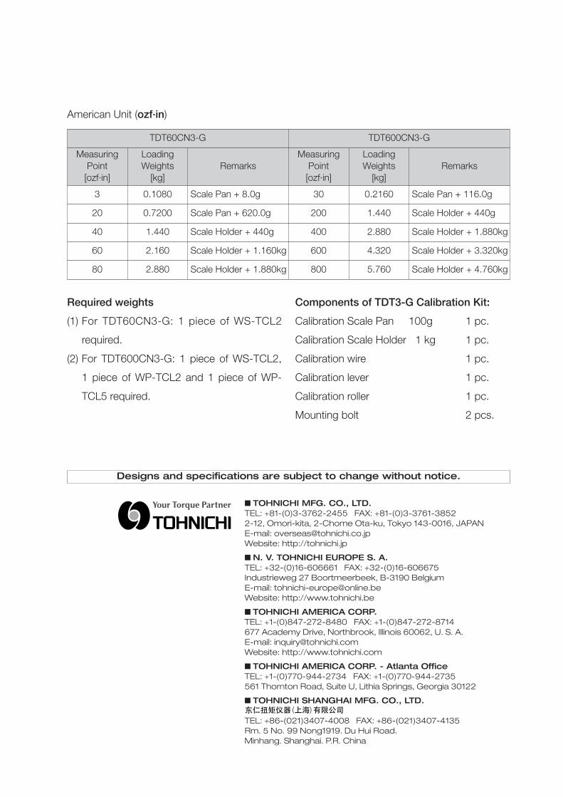
Required weights
(1) For TDT60CN3-G: 1 piece of WS-TCL2
required.
(2) For TDT600CN3-G: 1 piece of WS-TCL2,
1 piece of WP-TCL2 and 1 piece of WP-
TCL5 required.
American Unit (ozf·in)
TDT60CN3-G TDT600CN3-G
Measuring Loading Measuring Loading Point Weights Remarks Point Weights Remarks[ozf·in] [kg] [ozf·in] [kg]
3 0.1080 Scale Pan + 8.0g 30 0.2160 Scale Pan + 116.0g
20 0.7200 Scale Pan + 620.0g 200 1.440 Scale Holder + 440g
40 1.440 Scale Holder + 440g 400 2.880 Scale Holder + 1.880kg
60 2.160 Scale Holder + 1.160kg 600 4.320 Scale Holder + 3.320kg
80 2.880 Scale Holder + 1.880kg 800 5.760 Scale Holder + 4.760kg
Components of TDT3-G Calibration Kit:
Calibration Scale Pan 100g 1 pc.
Calibration Scale Holder 1 kg 1 pc.
Calibration wire 1 pc.
Calibration lever 1 pc.
Calibration roller 1 pc.
Mounting bolt 2 pcs.