digital terrestrial television mheg-5 specication
TRANSCRIPT
muxGROUP
d
Digital Terrestrial Television
MHEG-5 SpeciÞcation
Revision: 1.0Revised: 28 February 1998 20:16© BDB 1997-1998, ConÞdential

COPYRIGHT BRITISH DIGITAL BROADCASTING PLC
This document and the information contained herein is the subject of copyright and intellec-tual property rights under international convention. All rights reserved. No part of this docu-ment may be produced, stored in a retrieval system or transmitted in any form or by any means, electronic, mechanical, or optical, in whole or in part, without the prior written per-mission of British Digital Broadcasting PLC which holds the copyright on behalf of all DMUX group members.
2 Version: 1.0Last Updated: 28 February 1998 20:16Date Printed: 28 February 1998 20:19
File: cover

muxGROUP
d
Digital Terrestrial Television MHEG-5 SpeciÞcation© BDB 1997-1998, ConÞdential
1 Status of this document - - - - - - - - - - - - - - - - - - - - - - - - - - - - - - - - - - - - - - - - - - - - - - - - 9
2 The User Experience- - - - - - - - - - - - - - - - - - - - - - - - - - - - - - - - - - - - - - - - - - - - - - - - - 11
2.1 Introduction . . . . . . . . . . . . . . . . . . . . . . . . . . . . . . . . . . . . . . . . . . . . . . . . . . . . . . . . . 112.1.1 Visual Appearance 11
2.2 User Navigation . . . . . . . . . . . . . . . . . . . . . . . . . . . . . . . . . . . . . . . . . . . . . . . . . . . . . . 13
2.3 Remote Control Functions. . . . . . . . . . . . . . . . . . . . . . . . . . . . . . . . . . . . . . . . . . . . . . 15
2.4 Channel Selections within an Information Service . . . . . . . . . . . . . . . . . . . . . . . . . . . 16
2.5 Use of Video within an Information Service . . . . . . . . . . . . . . . . . . . . . . . . . . . . . . . . 17
3 MHEG-5 Engine Profile - - - - - - - - - - - - - - - - - - - - - - - - - - - - - - - - - - - - - - - - - - - - - - 19
3.1 Basic SpeciÞcation . . . . . . . . . . . . . . . . . . . . . . . . . . . . . . . . . . . . . . . . . . . . . . . . . . . 19
3.2 Object interchange format . . . . . . . . . . . . . . . . . . . . . . . . . . . . . . . . . . . . . . . . . . . . . . 19
3.3 Set of Classes. . . . . . . . . . . . . . . . . . . . . . . . . . . . . . . . . . . . . . . . . . . . . . . . . . . . . . . . 19
3.4 Set of Features . . . . . . . . . . . . . . . . . . . . . . . . . . . . . . . . . . . . . . . . . . . . . . . . . . . . . . . 213.4.1 GetEngineSupport ÒfeatureÓ strings 21
3.4.1.1 Audio Stream Decoders 223.4.1.2 Scaling 22
3.5 Content data encoding . . . . . . . . . . . . . . . . . . . . . . . . . . . . . . . . . . . . . . . . . . . . . . . . . 223.5.1 Use of negative hook values 23
3.5.2 BitmapObjects 24
3.5.3 Stream ÒmemoryÓ formats 24
3.6 UserInput Registers . . . . . . . . . . . . . . . . . . . . . . . . . . . . . . . . . . . . . . . . . . . . . . . . . . . 24
3.7 Semantic constraints on MHEG-5 applications. . . . . . . . . . . . . . . . . . . . . . . . . . . . . . 25
3.8 EngineEvent. . . . . . . . . . . . . . . . . . . . . . . . . . . . . . . . . . . . . . . . . . . . . . . . . . . . . . . . . 25
3.9 Protocol mapping and external interaction . . . . . . . . . . . . . . . . . . . . . . . . . . . . . . . . . 25
3.10 Resident Programs. . . . . . . . . . . . . . . . . . . . . . . . . . . . . . . . . . . . . . . . . . . . . . . . . . . . 263.10.1 Service Selection 26
3.10.1.1 Extracts from DAVIC documents 263.10.1.2 Additional semantics 27
3.10.2 Checking References 273.10.2.1 CheckContentRef 273.10.2.2 CheckObjectRef 273.10.2.3 Uncalled for events 27
3.11 Limitations on Standard Data-Types . . . . . . . . . . . . . . . . . . . . . . . . . . . . . . . . . . . . . . 28
3.12 Special Engine Behaviour . . . . . . . . . . . . . . . . . . . . . . . . . . . . . . . . . . . . . . . . . . . . . . 283.12.1 Killing Applications 28
3.13 Not Required Features . . . . . . . . . . . . . . . . . . . . . . . . . . . . . . . . . . . . . . . . . . . . . . . . . 28
Version: 1.0 3Last Updated: 28 February 1998 20:16Date Printed: 28 February 1998 20:19File: MHEG_proÞleTOC

muxGROUP
d
Digital Terrestrial Television MHEG-5 SpeciÞcation© BDB 1997-1998, ConÞdential
4 MHEG Engine Graphics Model - - - - - - - - - - - - - - - - - - - - - - - - - - - - - - - - - - - - - - - - - - 29
4.1 The Graphics Plane . . . . . . . . . . . . . . . . . . . . . . . . . . . . . . . . . . . . . . . . . . . . . . . . . . . 29
4.2 The Colour Palette . . . . . . . . . . . . . . . . . . . . . . . . . . . . . . . . . . . . . . . . . . . . . . . . . . . . 30
4.3 Colour Representation . . . . . . . . . . . . . . . . . . . . . . . . . . . . . . . . . . . . . . . . . . . . . . . . . 404.3.1 Colour Space 40
4.3.2 Gamma 40
4.3.3 Direct/Absolute colours 40
4.3.4 PNG Modes 40
4.4 Overlapping Visibles . . . . . . . . . . . . . . . . . . . . . . . . . . . . . . . . . . . . . . . . . . . . . . . . . . 414.4.1 Transparency & Overlapping Visibles 41
4.4.2 RTGraphics & Overlapping Visibles 42
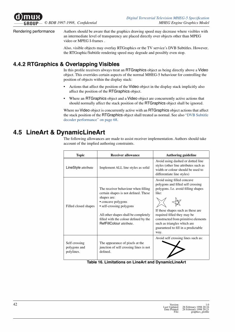
4.5 LineArt & DynamicLineArt . . . . . . . . . . . . . . . . . . . . . . . . . . . . . . . . . . . . . . . . . . . . 42
4.6 PNG Aspect ratios . . . . . . . . . . . . . . . . . . . . . . . . . . . . . . . . . . . . . . . . . . . . . . . . . . . . 43
4.7 Numbers of Objects . . . . . . . . . . . . . . . . . . . . . . . . . . . . . . . . . . . . . . . . . . . . . . . . . . . 43
4.8 MPEG stills . . . . . . . . . . . . . . . . . . . . . . . . . . . . . . . . . . . . . . . . . . . . . . . . . . . . . . . . . 434.8.1 File format 43
4.8.2 Semantics 43
4.9 Graphics priority . . . . . . . . . . . . . . . . . . . . . . . . . . . . . . . . . . . . . . . . . . . . . . . . . . . . . 44
5 Text & Hypertext - - - - - - - - - - - - - - - - - - - - - - - - - - - - - - - - - - - - - - - - - - - - - - - - - - - 45
5.1 Character encoding . . . . . . . . . . . . . . . . . . . . . . . . . . . . . . . . . . . . . . . . . . . . . . . . . . . 455.1.1 Presentable text 45
5.1.2 Non-presented text 45
5.1.3 Type conversion 46
5.2 Fonts. . . . . . . . . . . . . . . . . . . . . . . . . . . . . . . . . . . . . . . . . . . . . . . . . . . . . . . . . . . . . . . 465.2.1 Downloading 46
5.2.1.1 Future compatibility 46
5.2.2 Embedded font 465.2.2.1 The DTG/RNIB font design project 465.2.2.2 Required sizes and styles 47
5.2.3 Invoking the font 47
5.2.4 FontAttributes 475.2.4.1 DAVIC-like long form 475.2.4.2 Short form 48
5.2.5 Character Set 48
5.2.6 TextColour 48
5.3 Text placement . . . . . . . . . . . . . . . . . . . . . . . . . . . . . . . . . . . . . . . . . . . . . . . . . . . . . . . 485.3.1 Font DeÞnition 48
5.3.2 ÒlogicalÓ text width rules 495.3.2.1 Computing ÒlogicalÓ text width 495.3.2.2 Logical text width 505.3.2.3 Converting measurements to display pixels 50
5.3.3 Control of text ßow 515.3.3.1 Line breaking 51
4 Version: 1.0Last Updated: 28 February 1998 20:16Date Printed: 28 February 1998 20:19
File: MHEG_proÞleTOC

muxGROUP
d
Digital Terrestrial Television MHEG-5 SpeciÞcation© BDB 1997-1998, ConÞdential
5.3.3.2 Tabulation 525.3.3.3 Line spacing 525.3.3.4 Reproducing JustiÞcation 53
5.4 Text Objects . . . . . . . . . . . . . . . . . . . . . . . . . . . . . . . . . . . . . . . . . . . . . . . . . . . . . . . . . 545.4.1 Text mark-up 54
5.4.1.1 White Space Characters 545.4.1.2 Format Control Mark-up 545.4.1.3 Future compatibility 55
5.4.2 Control of text ßow 55
5.5 HyperText Objects . . . . . . . . . . . . . . . . . . . . . . . . . . . . . . . . . . . . . . . . . . . . . . . . . . . . 555.5.1 HyperText anchors 55
5.6 Rendering Text. . . . . . . . . . . . . . . . . . . . . . . . . . . . . . . . . . . . . . . . . . . . . . . . . . . . . . . 565.6.1 Placing character cells 56
5.6.2 Rendering within character cells 565.6.2.1 Rendering technology 57
5.7 Entry Fields . . . . . . . . . . . . . . . . . . . . . . . . . . . . . . . . . . . . . . . . . . . . . . . . . . . . . . . . . 57
5.8 Character repertoire . . . . . . . . . . . . . . . . . . . . . . . . . . . . . . . . . . . . . . . . . . . . . . . . . . . 58
6 Receiver Requirements - - - - - - - - - - - - - - - - - - - - - - - - - - - - - - - - - - - - - - - - - - - - - - - 65
6.1 Introduction . . . . . . . . . . . . . . . . . . . . . . . . . . . . . . . . . . . . . . . . . . . . . . . . . . . . . . . . . 65
6.2 Auto Start Application . . . . . . . . . . . . . . . . . . . . . . . . . . . . . . . . . . . . . . . . . . . . . . . . . 65
6.3 Auto Kill Application . . . . . . . . . . . . . . . . . . . . . . . . . . . . . . . . . . . . . . . . . . . . . . . . . 65
6.4 Auto Kill Stream Decoders . . . . . . . . . . . . . . . . . . . . . . . . . . . . . . . . . . . . . . . . . . . . . 656.4.1 Stream inheritance by applications 65
6.5 Application Interaction with user Control of Decoders. . . . . . . . . . . . . . . . . . . . . . . . 676.5.1 Audio Decoder 67
6.5.2 Subtitle Decoder 67
6.6 Application impact on stream decoder speciÞcation. . . . . . . . . . . . . . . . . . . . . . . . . . 686.6.1 DVB Subtitle decoder performance 68
6.6.2 Drawing space for RTGraphics 68
6.6.3 Video decoder performance 68
6.6.4 Video Scaling 686.6.4.1 Video object placement 69
6.7 Persistent storage . . . . . . . . . . . . . . . . . . . . . . . . . . . . . . . . . . . . . . . . . . . . . . . . . . . . . 696.7.1 Storage of Þle names 70
6.7.2 Possible uses of persistent storage (informative) 70
6.8 Reference Decoder Model . . . . . . . . . . . . . . . . . . . . . . . . . . . . . . . . . . . . . . . . . . . . . . 70
6.9 Application Stacking . . . . . . . . . . . . . . . . . . . . . . . . . . . . . . . . . . . . . . . . . . . . . . . . . . 71
7 Object carousel Profile for UK DTT - - - - - - - - - - - - - - - - - - - - - - - - - - - - - - - - - - - - - - 73
7.1 Introduction . . . . . . . . . . . . . . . . . . . . . . . . . . . . . . . . . . . . . . . . . . . . . . . . . . . . . . . . . 73
Version: 1.0 5Last Updated: 28 February 1998 20:16Date Printed: 28 February 1998 20:19File: MHEG_proÞleTOC

muxGROUP
d
Digital Terrestrial Television MHEG-5 SpeciÞcation© BDB 1997-1998, ConÞdential
7.2 Object Carousel ProÞle . . . . . . . . . . . . . . . . . . . . . . . . . . . . . . . . . . . . . . . . . . . . . . . . 737.2.1 DSM-CC Sections 73
7.2.2 Data Carousel 747.2.2.1 General 747.2.2.2 DownloadInfoIndication 747.2.2.3 DownloadServerInitiate 747.2.2.4 ModuleInfo 757.2.2.5 ServiceGatewayInfo 76
7.2.3 The Object Carousel 777.2.3.1 BIOP Generic Object Message 777.2.3.2 BIOP FileMessage 787.2.3.3 BIOP DirectoryMessage 797.2.3.4 BIOP StreamMessage 807.2.3.5 BIOP Interoperable Object References 82
7.2.4 Assignment and use of transactionId values 87
7.2.5 Mapping of objects to data carousel modules 89
7.2.6 Compression of modules 89
7.3 Tag Mapping . . . . . . . . . . . . . . . . . . . . . . . . . . . . . . . . . . . . . . . . . . . . . . . . . . . . . . . . 907.3.1 MHEG-5 ComponentTags to DSM-CC association_tags 90
7.3.2 DSM-CC association_tags to DVB component_tags 90
7.4 Example of an Object Carousel . . . . . . . . . . . . . . . . . . . . . . . . . . . . . . . . . . . . . . . . . . 92
7.5 Application IdentiÞcation and Boot. . . . . . . . . . . . . . . . . . . . . . . . . . . . . . . . . . . . . . . 947.5.1 Introduction 94
7.5.2 Information in the PMT 947.5.2.1 Generic Application IdentiÞcation 947.5.2.2 SpeciÞc Application IdentiÞcation 957.5.2.3 Other Related PMT Descriptors 967.5.2.4 Example Use of application_descriptor 96
7.5.3 Information in the DSI 987.5.3.1 Specifying an Initial Object 987.5.3.2 Example Use of DSI userInfo Field 99
7.5.4 Locating the Initial Object 99
7.5.5 Steps Required to Identify and Boot Application 100
8 Name Mapping - - - - - - - - - - - - - - - - - - - - - - - - - - - - - - - - - - - - - - - - - - - - - - - - - - - - 101
8.1 Names within the receiver . . . . . . . . . . . . . . . . . . . . . . . . . . . . . . . . . . . . . . . . . . . . . 101
8.2 MHEG-5 Component tags . . . . . . . . . . . . . . . . . . . . . . . . . . . . . . . . . . . . . . . . . . . . . 101
8.3 DAVIC deÞnitions . . . . . . . . . . . . . . . . . . . . . . . . . . . . . . . . . . . . . . . . . . . . . . . . . . . 1018.3.1 Stream Events and Normal Play Time Mapping 101
8.3.2 Namespace Mapping 101
8.3.3 MHEG-5 Object References 1028.3.3.1 Mapping Rules for GroupIdentiÞer 1028.3.3.2 Shorthand Notation 1038.3.3.3 Other Service Gateways 103
8.3.4 MHEG-5 Content References 1038.3.4.1 DSMCC Stream Objects 103
8.3.5 URL Format for Access to Broadcast Services 1048.3.5.1 Introduction 104
6 Version: 1.0Last Updated: 28 February 1998 20:16Date Printed: 28 February 1998 20:19
File: MHEG_proÞleTOC

muxGROUP
d
Digital Terrestrial Television MHEG-5 SpeciÞcation© BDB 1997-1998, ConÞdential
8.3.5.2 Numerical format 104
9 MHEG-5 Authoring Guidelines - - - - - - - - - - - - - - - - - - - - - - - - - - - - - - - - - - - - - - - - 107
9.1 Introduction . . . . . . . . . . . . . . . . . . . . . . . . . . . . . . . . . . . . . . . . . . . . . . . . . . . . . . . . 107
9.2 Avoiding confusion with navigator functions . . . . . . . . . . . . . . . . . . . . . . . . . . . . . . 1079.2.1 Use of user inputs 107
9.3 Use of the ÒTextÓ function. . . . . . . . . . . . . . . . . . . . . . . . . . . . . . . . . . . . . . . . . . . . . 1089.3.1 The traditional ÒteletextÓ key 108
9.3.2 Accessing Additional Programme Information 109
9.3.3 ÒTextÓ has no effect 109
9.4 Changing Applications at Programme (Event) boundaries . . . . . . . . . . . . . . . . . . . . 110
9.5 MHEG streams . . . . . . . . . . . . . . . . . . . . . . . . . . . . . . . . . . . . . . . . . . . . . . . . . . . . . 111
9.6 Use of the display . . . . . . . . . . . . . . . . . . . . . . . . . . . . . . . . . . . . . . . . . . . . . . . . . . . 1119.6.1 Visible Area 111
9.6.2 Scene Aspect Ratio 111
9.7 Use of stream decoders . . . . . . . . . . . . . . . . . . . . . . . . . . . . . . . . . . . . . . . . . . . . . . . 111
9.8 Missed events. . . . . . . . . . . . . . . . . . . . . . . . . . . . . . . . . . . . . . . . . . . . . . . . . . . . . . . 111
9.9 File naming . . . . . . . . . . . . . . . . . . . . . . . . . . . . . . . . . . . . . . . . . . . . . . . . . . . . . . . . 111
9.10 Text and HyperText encoding . . . . . . . . . . . . . . . . . . . . . . . . . . . . . . . . . . . . . . . . . . 112
10 References- - - - - - - - - - - - - - - - - - - - - - - - - - - - - - - - - - - - - - - - - - - - - - - - - - - - - - - 113
10.1 ETSI. . . . . . . . . . . . . . . . . . . . . . . . . . . . . . . . . . . . . . . . . . . . . . . . . . . . . . . . . . . . . . 113
10.2 CENELEC . . . . . . . . . . . . . . . . . . . . . . . . . . . . . . . . . . . . . . . . . . . . . . . . . . . . . . . . . 113
10.3 ISO/IEC . . . . . . . . . . . . . . . . . . . . . . . . . . . . . . . . . . . . . . . . . . . . . . . . . . . . . . . . . . . 114
10.4 DVB. . . . . . . . . . . . . . . . . . . . . . . . . . . . . . . . . . . . . . . . . . . . . . . . . . . . . . . . . . . . . . 114
10.5 ITU . . . . . . . . . . . . . . . . . . . . . . . . . . . . . . . . . . . . . . . . . . . . . . . . . . . . . . . . . . . . . . 114
10.6 Apple Corporation Inc. . . . . . . . . . . . . . . . . . . . . . . . . . . . . . . . . . . . . . . . . . . . . . . . 115
10.7 W3C. . . . . . . . . . . . . . . . . . . . . . . . . . . . . . . . . . . . . . . . . . . . . . . . . . . . . . . . . . . . . . 115
10.8 DAVIC . . . . . . . . . . . . . . . . . . . . . . . . . . . . . . . . . . . . . . . . . . . . . . . . . . . . . . . . . . . . 115
Version: 1.0 7Last Updated: 28 February 1998 20:16Date Printed: 28 February 1998 20:19File: MHEG_proÞleTOC

muxGROUP
d
Digital Terrestrial Television MHEG-5 SpeciÞcation© BDB 1997-1998, ConÞdential
8 Version: 1.0Last Updated: 28 February 1998 20:16Date Printed: 28 February 1998 20:19
File: MHEG_proÞleTOC

1 Status of this document
This document is the substantially complete speciÞcation for the MHEG-5 system to be implemented in the Þrst generation of Digital Terrestrial TV receivers to be deployed the UK.
The technical details represent a widely supported working assumption. However, changes may be introduced as issues are uncovered and where clariÞcation is required.
The following issues of detail are under review at the time of publication:
¥ The details of the deÞnition of the colour palette, see ÒThe Colour PaletteÓ on page 30.
¥ The details of the method for coding text mark-up, ÒText ObjectsÓ on page 54.
¥ The details of the character table to be used, ÒCharacter repertoireÓ on page 58.
¥ The details for how a receiver identiÞes which application to launch (See ÒApplication IdentiÞcation and BootÓ on page 94) (topic under discussion within the DVB).
In addition certain topics are recognised as projects for future work:
¥ The Reference Decoder Model see page 70.
¥ The broadcaster MHEG-5 Authoring Guidelines see page 107.
Version: 1.0 9Last Updated: 28 February 1998 20:16Date Printed: 28 February 1998 20:19File: doc_status

muxGROUP
d
Digital Terrestrial Television MHEG-5 SpeciÞcation© BDB 1997-1998, ConÞdential Status of this document
10 Version: 1.0Last Updated: 28 February 1998 20:16Date Printed: 28 February 1998 20:19
File: doc_status
2 The User Experience
2.1 IntroductionThis section looks at the behaviour seen by the user. It is provided to give context to the receiver speciÞcations. However, much of the behaviour shown here results from functional-ity coded into the broadcast application, rather than the receiver.
This broadcaster controlled behaviour should be seen as a concept model for how services may appear. As broadcasters develop their concepts for services, and gain experience from user feed-back, the detail of the behaviour they implement is likely to evolve.
2.1.1 Visual Appearance
Balance of AV and MHEG
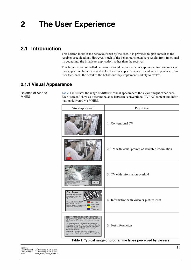
Table 1 illustrates the range of different visual appearances the viewer might experience. Each ÒscreenÓ shows a different balance between Òconventional TVÓ AV content and infor-mation delivered via MHEG.
Visual Appearance Description
1. Conventional TV
2. TV with visual prompt of available information
3. TV with information overlaid
4. Information with video or picture inset
5. Just information
Table 1. Typical range of programme types perceived by viewers
Walking holidays in the jungles of Sarawakstart from £599 for 7 night fromFarm Road Holidays TEXT
Car SalesNew car registrationsthis August were 3%up on last year.
Car production in 1997was 5% up. 150,000unsold cars are now storedin around the country
Main IndexNews IndexNext NewsTV Listings
COOK TO ATTEND SADDAM CRISIS MEETINGForeign Secretary Robin Cook is to hold talks with hisUS, Russian and French counterparts over the Iraqcrisis.
The Geneva meeting has been scheduled for theearly hours of tomorrow. The move follows a claim bythe Russian foreign minister that he had hammeredout a possible deal with Iraq in the row over UNweapons inspections.
Meanwhile, President Clinton has ordered B-52bombers and Stealth fighters to beef US forces in theGulf.
Version: 1.0 11Last Updated: 28 February 1998 20:16Date Printed: 28 February 1998 20:19File: user_navigation_model.fr

muxGROUP
d
Digital Terrestrial Television MHEG-5 SpeciÞcation© BDB 1997-1998, ConÞdential The User Experience
Time and Space The user may see a change in appearance either when they change channel or as a service changes through time.
Walking holidays in the jungles of Sarawakstart from £599 for 7 night fromFarm Road Holidays TEXT
COOK TO ATTEND SADDAM CRISIS MEETINGForeign Secretary Robin Cook is to hold talks with hisUS, Russian and French counterparts over the Iraqcrisis.
The Geneva meeting has been scheduled for theearly hours of tomorrow. The move follows a claim bythe Russian foreign minister that he had hammeredout a possible deal with Iraq in the row over UNweapons inspections.
Meanwhile, President Clinton has ordered B-52bombers and Stealth fighters to beef US forces in theGulf.
Car SalesNew car registrationsthis August were 3%up on last year.
Car production in 1997was 5% up. 150,000unsold cars are now storedin around the country
Main IndexNews IndexNext NewsTV Listings
Tim
e
TV Service 1 TV Service 2 Information Service
COOK TO ATTEND SADDAM CRISIS MEETINGForeign Secretary Robin Cook is to hold talks with hisUS, Russian and French counterparts over the Iraqcrisis.
The Geneva meeting has been scheduled for theearly hours of tomorrow. The move follows a claim bythe Russian foreign minister that he had hammeredout a possible deal with Iraq in the row over UNweapons inspections.
Meanwhile, President Clinton has ordered B-52bombers and Stealth fighters to beef US forces in theGulf.
Service
Figure 1. What might be seen across channels and through time
12 Version: 1.0Last Updated: 28 February 1998 20:16Date Printed: 28 February 1998 20:20
File: user_navigation_model.fr
muxGROUP
d
Digital Terrestrial Television MHEG-5 SpeciÞcationThe User Experience © BDB 1997-1998, ConÞdential
2.2 User Navigation
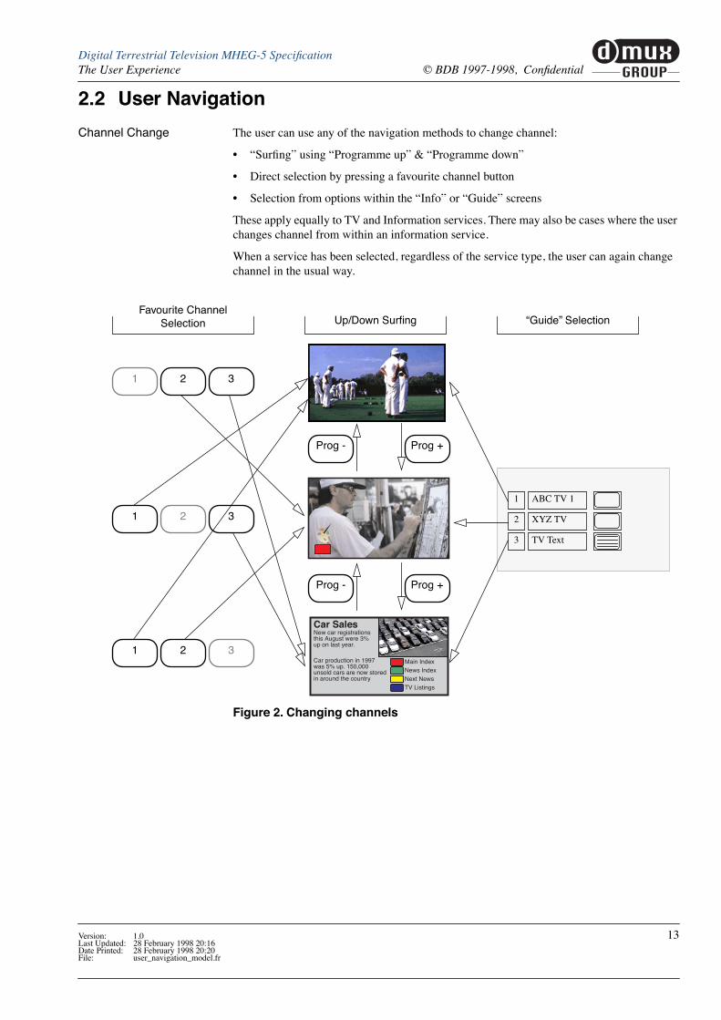
Channel Change The user can use any of the navigation methods to change channel:
¥ ÒSurÞngÓ using ÒProgramme upÓ & ÒProgramme downÓ
¥ Direct selection by pressing a favourite channel button
¥ Selection from options within the ÒInfoÓ or ÒGuideÓ screens
These apply equally to TV and Information services. There may also be cases where the user changes channel from within an information service.
When a service has been selected, regardless of the service type, the user can again change channel in the usual way.
Car SalesNew car registrationsthis August were 3%up on last year.
Car production in 1997was 5% up. 150,000unsold cars are now storedin around the country
Main IndexNews IndexNext NewsTV Listings
Figure 2. Changing channels
1 2 3
1 2 3
1 2 3
Prog - Prog +
Prog - Prog +
Favourite Channel Selection Up/Down SurÞng ÒGuideÓ Selection
ABC TV 1
XYZ TV
TV Text
1
2
3
Version: 1.0 13Last Updated: 28 February 1998 20:16Date Printed: 28 February 1998 20:20File: user_navigation_model.fr

muxGROUP
d
Digital Terrestrial Television MHEG-5 SpeciÞcation© BDB 1997-1998, ConÞdential The User Experience
The ÒTextÓ Button The effect of the ÒTextÓ button may vary slightly from programme to programme.
Car SalesNew car registrationsthis August were 3%up on last year.
Car production in 1997was 5% up. 150,000unsold cars are now storedin around the country
Main IndexNews IndexNext NewsTV Listings
COOK TO ATTEND SADDAM CRISIS MEETINGForeign Secretary Robin Cook is to hold talks with hisUS, Russian and French counterparts over the Iraqcrisis.
The Geneva meeting has been scheduled for theearly hours of tomorrow. The move follows a claim bythe Russian foreign minister that he had hammeredout a possible deal with Iraq in the row over UNweapons inspections.
Meanwhile, President Clinton has ordered B-52bombers and Stealth fighters to beef US forces in theGulf.
Info Pack Courses Next Week Reveal
Text
Figure 3. Using the text button
Text
Text
Text
Text
Text
Programme has no associated text.
Service is linked to a full text serv-ice.
Service is linked to a full text serv-ice.
Text service has no associated TV programme.
User SelectsThis Channel
Car SalesNew car registrationsthis August were 3%up on last year.
Car production in 1997was 5% up. 150,000unsold cars are now storedin around the country
Main IndexNews IndexNext NewsTV Listings
Text
Text
Text service can be viewed as a TV service.
See ÒThe traditional ÒteletextÓkeyÓ on page 108
See ÒAccessing AdditionalProgramme InformationÓ on
page 109
COOK TO ATTEND SADDAM CRISIS MEETINGForeign Secretary Robin Cook is to hold talks with hisUS, Russian and French counterparts over the Iraqcrisis.
The Geneva meeting has been scheduled for theearly hours of tomorrow. The move follows a claim bythe Russian foreign minister that he had hammeredout a possible deal with Iraq in the row over UNweapons inspections.
Meanwhile, President Clinton has ordered B-52bombers and Stealth fighters to beef US forces in theGulf.
Red
Text
Programme is linked to addi-tional informa-tion on the programme.
14 Version: 1.0Last Updated: 28 February 1998 20:16Date Printed: 28 February 1998 20:20
File: user_navigation_model.fr

muxGROUP
d
Digital Terrestrial Television MHEG-5 SpeciÞcationThe User Experience © BDB 1997-1998, ConÞdential
2.3 Remote Control FunctionsFigure 4 illustrates the functions of the receiver remote control. This is provided to help explain the Òfunction groupsÓ. The physical appearance of the remote control and the meth-ods of interaction delivering the required functions may be quite different from the one illus-trated.
Receiver Group These provide the most frequently used receiver control functions.
They have the same effect whether the viewer is watching a TV service, an MHEG service or using other receiver screens. For example, the ÒProgram upÓ & ÒProgram downÓ always have the effect of changing channel.
All other receiver speciÞc functions (e.g. to invoke the receiver set-up screens) are also within this group.
ÒEnteredÓ Group This group is available for use by receiver speciÞc functions while the viewer is watching TV, surÞng between channels or using receiver interaction screens. After the viewer enters a broadcast application these functions become exclusively used by the application.
Numeric set The numeric set can be used by the application for navigation (e.g. selecting from list of options labelled 1-9) or for entering numbers (e.g. to enter a number in a maths quiz).
Pointer set The pointer set provide ÒmouseÓ like ability to ÒtouchÓ and ÒmanipulateÓ things such as but-tons and sliders.
ÒSelectedÓ Group When the viewer is watching TV these keys have no effect.
After selecting an MHEG service these keys become active allowing the user to select between a menu of options. These keys may also be used for navigating around receiver originated screens such as the ÒInfoÓ & ÒGuideÓ screens.
1
Figure 4. Remote Control Function Groups
2 3
4 5 6
7 8 9
0
Vol - Vol +Cancel
Power
Text
Info
Guide
Prog +
Prog -
Red Green Yellow Blue
Left Select
Up
Down
Right
Mute
Subtitle
Wide
Receiver GroupÒEnteredÓ Group
ÒSelectedÓ Group
Pointer set
Numeric set
Version: 1.0 15Last Updated: 28 February 1998 20:16Date Printed: 28 February 1998 20:20File: user_navigation_model.fr

muxGROUP
d Digital Terrestrial Television MHEG-5 SpeciÞcation© BDB 1997-1998, ConÞdential The User Experience
2.4 Channel Selections within an Information ServiceMHEG services can provide facilities to change channel. For example, they may provide listings of current programmes and the ability to select a programme.
The effect of changing channel from an MHEG application is exactly the same as if the user selected a channel from the receiverÕs ÒGuideÓ.
Walking holidays in the jungles of Sarawakstart from £599 for 7 night fromFarm Road Holidays TEXT
Car SalesNew car registrationsthis August were 3%up on last year.
Car production in 1997was 5% up. 150,000unsold cars are now storedin around the country
Main IndexNews IndexNext NewsTV Listings
COOK TO ATTEND SADDAM CRISIS MEETINGForeign Secretary Robin Cook is to hold talks with hisUS, Russian and French counterparts over the Iraqcrisis.
The Geneva meeting has been scheduled for theearly hours of tomorrow. The move follows a claim bythe Russian foreign minister that he had hammeredout a possible deal with Iraq in the row over UNweapons inspections.
Meanwhile, President Clinton has ordered B-52bombers and Stealth fighters to beef US forces in theGulf.
Prog - Prog +
Prog - Prog +
Info Pack Courses Next Week Reveal
Various Navi-gation Steps
Prog - Prog +
Figure 5. Using a TV listings page to change channel
Text
Text
Text
Text
ABC TV 1
XYZ TV
TV Text
1
2
3
Red
Text
Select ÒChannel GuideÓ Page
Select Channel from ÒChannel GuideÓ Page
16 Version: 1.0Last Updated: 28 February 1998 20:16Date Printed: 28 February 1998 20:20
File: user_navigation_model.fr
muxGROUP
dDigital Terrestrial Television MHEG-5 SpeciÞcationThe User Experience © BDB 1997-1998, ConÞdential
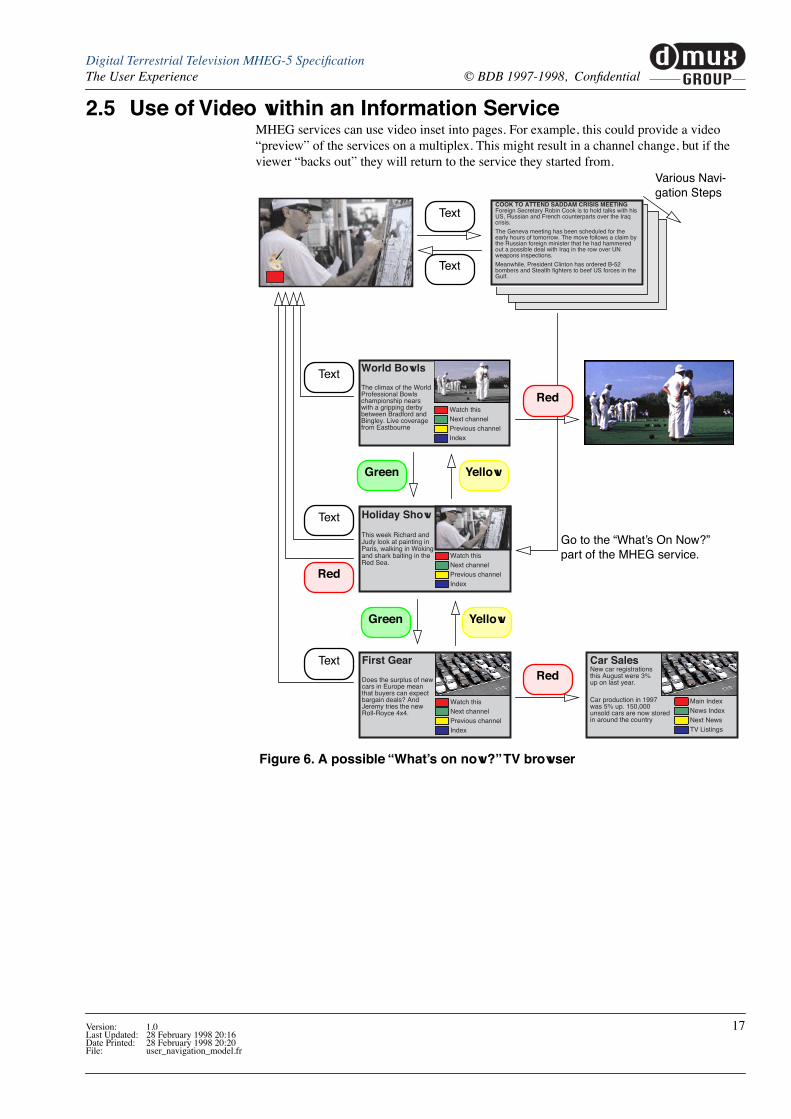
2.5 Use of Video within an Information ServiceMHEG services can use video inset into pages. For example, this could provide a video ÒpreviewÓ of the services on a multiplex. This might result in a channel change, but if the viewer Òbacks outÓ they will return to the service they started from.
Holiday Show
This week Richard andJudy look at painting inParis, walking in Wokingand shark baiting in theRed Sea.
Watch thisNext channelPrevious channelIndex
World Bowls
The climax of the WorldProfessional Bowlschampionship nearswith a gripping derbybetween Bradford andBingley. Live coveragefrom Eastbourne
Watch thisNext channelPrevious channelIndex
First Gear
Does the surplus of newcars in Europe meanthat buyers can expectbargain deals? AndJeremy tries the newRoll-Royce 4x4.
Watch thisNext channelPrevious channelIndex
Car SalesNew car registrationsthis August were 3%up on last year.
Car production in 1997was 5% up. 150,000unsold cars are now storedin around the country
Main IndexNews IndexNext NewsTV Listings
Figure 6. A possible ÒWhatÕs on now?Ó TV browser
Red
Text
Text
COOK TO ATTEND SADDAM CRISIS MEETINGForeign Secretary Robin Cook is to hold talks with hisUS, Russian and French counterparts over the Iraqcrisis.
The Geneva meeting has been scheduled for theearly hours of tomorrow. The move follows a claim bythe Russian foreign minister that he had hammeredout a possible deal with Iraq in the row over UNweapons inspections.
Meanwhile, President Clinton has ordered B-52bombers and Stealth fighters to beef US forces in theGulf.
Various Navi-gation Steps
Red
Red
Text
Green Yellow
Green Yellow
Text
Text
Go to the ÒWhatÕs On Now?Ó part of the MHEG service.
Version: 1.0 17Last Updated: 28 February 1998 20:16Date Printed: 28 February 1998 20:20File: user_navigation_model.fr

muxGROUP
d Digital Terrestrial Television MHEG-5 SpeciÞcation© BDB 1997-1998, ConÞdential The User Experience
18 Version: 1.0Last Updated: 28 February 1998 20:16Date Printed: 28 February 1998 20:21
File: user_navigation_model.fr

3 MHEG-5 Engine ProÞle
This section provides the detail speciÞcation of the MHEG engine required in Þrst genera-tion digital TV receivers. This speciÞcation is an Òapplication domainÓ in the terms set out in Annex D of ISO/IEC 13522-5.
This is Òapplication domainÓ is referred to as ÒUKEngineProÞle1Ó
3.1 Basic SpeciÞcationThe engine shall be compliant with the ISO/IEC 13522-5 (MHEG-5) speciÞcation for a Hypermedia presentation engine using the Òapplication domainÓ deÞnition provided by this document.
The ISO/IEC 13522-5 speciÞcation should be considered in conjunction with the work of the MHEG-5 Maintenance Task Force (MTF) published at:
http://www.fokus.gmd.de/ovma/mug/mtf/entry.htm
3.2 Object interchange formatThe ASN.1 notation deÞned in Annex A of ISO/IEC 13522-5 shall be used as the application interchange format. The encoding of the MHEG-5 objects from this ASN.1 syntax shall make use of the Distinguished Encoding Rules (DER) deÞned in ITU-T X.690.
3.3 Set of ClassesTable 2 identiÞes the classes that a receiver implementing the UKEngineProÞle1 shall implement.
Class
Abs
trac
t/C
oncr
ete[a
]
Req
uire
d(Y
/N[b
] )
Notes
Root A Y
Group A Y
Application C Y
Scene C Y
Ingredient A Y
Link C Y
Program A Y
ResidentProgram C Y See ÒResident ProgramsÓ on page 26
RemoteProgram C N
InterchangedProgram C N
Palette C N
Font C N See ÒText & HypertextÓ on page 45
CursorShape C N
Table 2. Classes supported by this engine proÞle (Sheet 1 of 2)
Version: 1.0 19Last Updated: 28 February 1998 20:16Date Printed: 28 February 1998 20:21File: engine_proÞle.fr

muxGROUP
d Digital Terrestrial Television MHEG-5 SpeciÞcation© BDB 1997-1998, ConÞdential MHEG-5 Engine ProÞle
a] Abstract classes are not ÒinterchangedÓ (i.e. not directly used) in UKEngineProÞle1 MHEG applications
b] ÔYÕ = yes, i.e. receivers implementing UKEngineProÞle1 shall support these classes. ÔNÕ = no, i.e. receivers implementing UKEngineProÞle1 are not required to support these classes. Also, classes marked ÔNÕ may not be completely deÞned in the UK context at this time.
Variable A Y
See Section 3.11 on page 28
BooleanVariable C Y
IntegerVariable C Y
OctetStringVariable C Y
ObjectRefVariable C Y
ContentRefVariable C Y
Presentable A Y
TokenManager A Y
TokenGroup C Y
ListGroup C Y
Visible A Y
Bitmap C YSee ÒBitmapObjectsÓ on page 24 & ÒMPEG stillsÓ on page 43.
LineArt A Y See ÒLineArt & DynamicLineArtÓ on page 42.
Rectangle C Y
DynamicLineArt C Y See ÒLineArt & DynamicLineArtÓ on page 42.
Text C Y See ÒText ObjectsÓ on page 54.
Stream C Y
Audio C YSee ÒAudio Stream DecodersÓ on page 22 &ÒStream ÒmemoryÓ formatsÓ on page 24.
Video C Y
RTGraphics C Y
Interactible A Y
Slider C Y
EntryField C Y See ÒEntry FieldsÓ on page 57.
HyperText C Y See ÒHyperText ObjectsÓ on page 55.
Button A Y
HotSpot C Y
PushButton C Y
SwitchButton C Y
Action C Y
Class
Abs
trac
t/C
oncr
ete[a
]
Req
uire
d(Y
/N[b
] )
Notes
Table 2. Classes supported by this engine proÞle (Sheet 2 of 2)
20 Version: 1.0Last Updated: 28 February 1998 20:16Date Printed: 28 February 1998 20:21
File: engine_proÞle.fr
muxGROUP
dDigital Terrestrial Television MHEG-5 SpeciÞcationMHEG-5 Engine ProÞle © BDB 1997-1998, ConÞdential
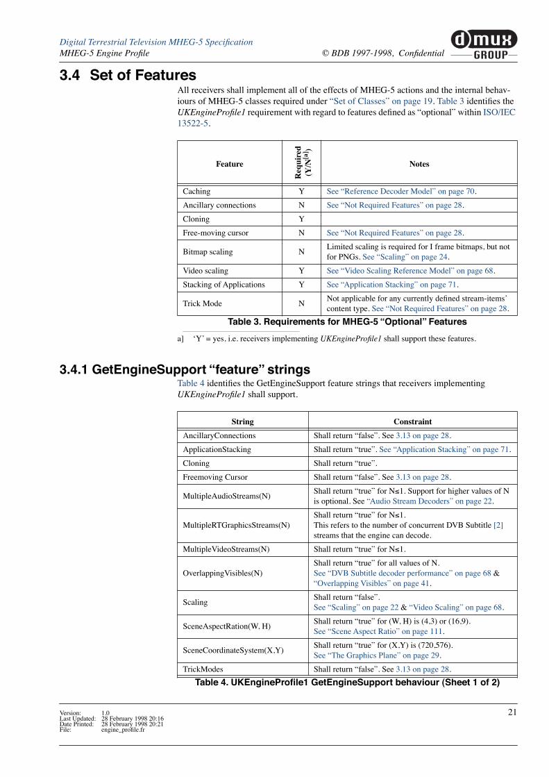
3.4 Set of FeaturesAll receivers shall implement all of the effects of MHEG-5 actions and the internal behav-iours of MHEG-5 classes required under ÒSet of ClassesÓ on page 19. Table 3 identiÞes the UKEngineProÞle1 requirement with regard to features deÞned as ÒoptionalÓ within ISO/IEC 13522-5.
a] ÔYÕ = yes, i.e. receivers implementing UKEngineProÞle1 shall support these features.
3.4.1 GetEngineSupport ÒfeatureÓ stringsTable 4 identiÞes the GetEngineSupport feature strings that receivers implementing UKEngineProÞle1 shall support.
Feature
Req
uire
d(Y
/N[a
] )
Notes
Caching Y See ÒReference Decoder ModelÓ on page 70.
Ancillary connections N See ÒNot Required FeaturesÓ on page 28.
Cloning Y
Free-moving cursor N See ÒNot Required FeaturesÓ on page 28.
Bitmap scaling NLimited scaling is required for I frame bitmaps, but not for PNGs. See ÒScalingÓ on page 24.
Video scaling Y See ÒVideo Scaling Reference ModelÓ on page 68.
Stacking of Applications Y See ÒApplication StackingÓ on page 71.
Trick Mode NNot applicable for any currently deÞned stream-itemsÕ content type. See ÒNot Required FeaturesÓ on page 28.
Table 3. Requirements for MHEG-5 ÒOptionalÓ Features
String Constraint
AncillaryConnections Shall return ÒfalseÓ. See 3.13 on page 28.
ApplicationStacking Shall return ÒtrueÓ. See ÒApplication StackingÓ on page 71.
Cloning Shall return ÒtrueÓ.
Freemoving Cursor Shall return ÒfalseÓ. See 3.13 on page 28.
MultipleAudioStreams(N)Shall return ÒtrueÓ for N£1. Support for higher values of N is optional. See ÒAudio Stream DecodersÓ on page 22.
MultipleRTGraphicsStreams(N)Shall return ÒtrueÓ for N£1. This refers to the number of concurrent DVB Subtitle [2] streams that the engine can decode.
MultipleVideoStreams(N) Shall return ÒtrueÓ for N£1.
OverlappingVisibles(N)Shall return ÒtrueÓ for all values of N.See ÒDVB Subtitle decoder performanceÓ on page 68 & ÒOverlapping VisiblesÓ on page 41.
ScalingShall return ÒfalseÓ.See ÒScalingÓ on page 22 & ÒVideo ScalingÓ on page 68.
SceneAspectRation(W, H)Shall return ÒtrueÓ for (W, H) is (4,3) or (16,9).See ÒScene Aspect RatioÓ on page 111.
SceneCoordinateSystem(X,Y)Shall return ÒtrueÓ for (X,Y) is (720,576). See ÒThe Graphics PlaneÓ on page 29.
TrickModes Shall return ÒfalseÓ. See 3.13 on page 28.
Table 4. UKEngineProÞle1 GetEngineSupport behaviour (Sheet 1 of 2)
Version: 1.0 21Last Updated: 28 February 1998 20:16Date Printed: 28 February 1998 20:21File: engine_proÞle.fr

muxGROUP
d Digital Terrestrial Television MHEG-5 SpeciÞcation© BDB 1997-1998, ConÞdential MHEG-5 Engine ProÞle
Unrecognised requests will always result in GetEngineSupport returning false. This implies that future MHEG engine implementations supporting more than these minimum features will recognise additional strings. These strings will have to be agreed by the DMux group so that consistency is maintained.
3.4.1.1 Audio Stream DecodersTwo types of audio decoder are considered in the context of the UKEngineProÞle1 MHEG engine:
1. Decode MPEG Audio [16] data ÒliveÓ from a stream as it is broadcast (e.g. the sound track for a TV programme).
2. Decode an MPEG Audio [16] object from memory (See ÒStream ÒmemoryÓ formatsÓ on page 24).
UKEngineProÞle1 receivers shall provide one MPEG Audio [16] decoder which can decode data either from a stream OR from an object in memory.
Facility for decoding AIFF-C [24] audio data is not part of UKEngineProÞle1. The meaning of MultipleAudioStreams(N) for N>1 has not yet been deÞned in the UK context.
3.4.1.2 ScalingGetEngineSupport with the feature string ÒScalingÓ shall return ÒfalseÓ in UKEngineProÞle1 to avoid confusion with the DAVIC 1.3 Part 09 semantic where this engine string applies to both bitmaps and video.
VideoScaling(X,Y) The GetEngineSupport with the feature string ÒVideoScaling(X,Y)Ó can be used to deter-mine the video scaling modes supported by an engine. UKEngineProÞle1 receivers shall support the following 2 options:
¥ Full screen video
¥ Quarter screen video
GetEngineSupport with the feature string ÒVideoScaling(X,Y)Ó indicates this by returning ÒtrueÓ when (X,Y) is (720,576) or (360,288).
See ÒVideo ScalingÓ on page 68.
3.5 Content data encodingTable 5 identiÞes the minimum set of coding of attributes that shall be supported by the engine.
VideoScaling(X,Y)Shall return ÒtrueÓ for (X,Y) is (720,576) and (360, 288). See ÒVideoScaling(X,Y)Ó on page 22 & ÒVideo ScalingÓ on page 68.
UKEngineProÞle(1)Shall return ÒtrueÓ when N=1 to indicate that the engine at least supports the minimum requirements of UKEngineProÞle1.
String Constraint
Table 4. UKEngineProÞle1 GetEngineSupport behaviour (Sheet 2 of 2)
Attribute Permissible values
FontAttributes See ÒFontAttributesÓ on page 47
FontName See ÒInvoking the fontÓ on page 47
AbsoluteColour See ÒDirect/Absolute coloursÓ on page 40
Table 5. Content table (Sheet 1 of 2)
22 Version: 1.0Last Updated: 28 February 1998 20:16Date Printed: 28 February 1998 20:21
File: engine_proÞle.fr

muxGROUP
dDigital Terrestrial Television MHEG-5 SpeciÞcationMHEG-5 Engine ProÞle © BDB 1997-1998, ConÞdential
Table 6 identiÞes the minimum set of data types that shall be supported by the engine for each type of content. It also identiÞes the content hook values for each data type.
a] The stream ÒStorageÓ attribute shall be ÒstreamÓ
b] The stream ÒStorageÓ attribute may be ÒstreamÓ or ÒmemoryÓ
3.5.1 Use of negative hook valuesNegative hook values are reserved for use by receiver manufacturers to signal manufacturer speciÞc encoding formats. These shall never be signalled by a broadcaster and may only be used by the manufacturer for local applications.
CharacterSet See ÒCharacter SetÓ on page 48
TransitionEffect (None speciÞed)
Type of content SpeciÞcation (Data Types)Hook values
Font (None speciÞed) See ÒDownloadingÓ on page 46
Palette (None speciÞed)
Bitmap
reserved 1
MPEG-2 Intra frame [15]See ÒMPEG stillsÓ on page 43
2
reserved 3
PNG bitmap 4
Text See ÒText mark-upÓ on page 54. 1
EntryField See ÒCharacter encodingÓ on page 45See ÒEntry FieldsÓ on page 57.
1
HyperText See ÒHyperText ObjectsÓ on page 55 1
Stream See Table 7.
LineArt (None speciÞed)
CursorShape (None speciÞed)
InterchangedProgram (None speciÞed)
Table 6. Encoding Table
Stream ComponentContent-hook
1[a] 2[b]
MPEG-1 video (ISO/IEC 11172-2)OrMPEG-2 video (ISO/IEC 13818-2)
x
MPEG-1 audio (ISO/IEC 11172-2) x x
DVB subtitling (ETS 300 743) x
Table 7. Content hooks for Streams
Attribute Permissible values
Table 5. Content table (Sheet 2 of 2)
Version: 1.0 23Last Updated: 28 February 1998 20:16Date Printed: 28 February 1998 20:21File: engine_proÞle.fr

muxGROUP
d Digital Terrestrial Television MHEG-5 SpeciÞcation© BDB 1997-1998, ConÞdential MHEG-5 Engine ProÞle
3.5.2 BitmapObjects
Scaling Scaling (the ScaleBitmap action) shall be supported for bitmap objects with MPEG I-frame content. See ÒMPEG stillsÓ on page 43. Scaling shall not be supported for bitmap objects using PNG bitmaps
Tiling Support for tiling is only required for PNG bitmaps.
Transparency Transparency can be encoded within the PNG bitmaps. Support for object level transparency is not required for any bitmap type. See ÒTransparency & Overlapping VisiblesÓ on page 41.
3.5.3 Stream ÒmemoryÓ formatsIn this proÞle the only StreamComponent that accepts a Storage speciÞcation of mem-ory is Audio. Video and RTGraphics can only be played from Stream.
Audio Each ÒÞleÓ of audio content is an OctetString carrying Audio elementary stream data. Each ÒÞleÓ delivers an integer number of audio access units and the Þrst byte of each Þle is the Þrst byte of an audio access unit.
3.6 UserInput RegistersTable 8 deÞnes the two input event registers (3 & 4) that shall be supported by receivers implementing UKEngineProÞle1. The DAVIC deÞned registers 1 & 2 are shown for infor-mation only. See ÒRemote Control FunctionsÓ on page 15.
a] The ÒSelectedÓ Group
b] The ÒEnteredÓ Group
UserInputEventTag
Function NameRegister Number
1 2 3[a] 4[b]
1 Up ✓ ✓ ✓
2 Down ✓ ✓ ✓
3 Left ✓ ✓ ✓
4 Right ✓ ✓ ✓
5-14 0, 1, 2, 3, 4, 5, 6, 7, 8, 9 respectively ✓ ✓
15 Select ✓ ✓ ✓
16 Cancel / Exit ✓ ✓ ✓
17 Help ✓ ✓
18-99 Reserved for future DAVIC speciÞcation
100 Red ✓ ✓
101 Green ✓ ✓
102 Yellow ✓ ✓
103 Blue ✓ ✓
104 Text ✓ ✓
105-128 Reserved for future UK speciÞcation
³129 Vendor speciÞc
Table 8. InputEvent Registers
24 Version: 1.0Last Updated: 28 February 1998 20:16Date Printed: 28 February 1998 20:21
File: engine_proÞle.fr

muxGROUP
dDigital Terrestrial Television MHEG-5 SpeciÞcationMHEG-5 Engine ProÞle © BDB 1997-1998, ConÞdential
3.7 Semantic constraints on MHEG-5 applicationsAs implied by the capabilities of the engine in ÒGetEngineSupport ÒfeatureÓ stringsÓ on page 21.
See also See ÒApplication impact on stream decoder speciÞcationÓ on page 68.
3.8 EngineEventTable 9 lists the minimum set of engine events that the engine is required to support.
3.9 Protocol mapping and external interaction
EventTagNotes
Name Value
< 0 Manufacturer speciÞc
Reserved 0 Reserved
QuitApp 1 See ÒKilling ApplicationsÓ on page 28
ObjectRefError 2
See ÒChecking ReferencesÓ on page 27
ObjectRefInvalid 3
ObjectRefOK 4
ContentRefError 5
ContentRefInvalid 6
ContentRefOK 7
TextFunction 8Generated when the user input function ÒTextÓ happens. See ÒRemote Control FunctionsÓ on page 15.
Reserved > 8 Reserved
Table 9. Required Engine Events
MHEG-5 entity Mapping needed Semantics
OpenConnection, CloseConnection
Mapping to connection management
Not required in UKEngineProÞle1.
See ÒNot Required FeaturesÓ on page 28.
RemoteProgram objects
Mapping to RemoteProgram call protocol in the application domain
Application name space in case a TransitionTo action uses the ConnectionTag parameter
Mapping to the name space of the application domain
Persistent storage name space
Mapping to the name space of the persistent storage
See ÒPersistent storageÓ on page 69.
Stream actionsMapping to the stream interface of the application domain See ÒStream Events and Normal
Play Time MappingÓ on page 101
Stream eventsMapping to stream states and stream events in the application domain
Table 10. Protocol Mapping
Version: 1.0 25Last Updated: 28 February 1998 20:16Date Printed: 28 February 1998 20:21File: engine_proÞle.fr

muxGROUP
d Digital Terrestrial Television MHEG-5 SpeciÞcation© BDB 1997-1998, ConÞdential MHEG-5 Engine ProÞle
3.10 Resident ProgramsTable 11 lists the ResidentPrograms that a UKEngineProÞle1 receiver shall implement.
a] See ÒType conversionÓ on page 46
DAVIC deÞnition Several of the functions in Table 11 are deÞned by DAVIC [27], others are under considera-tion. Where DAVIC [27] develops suitable deÞnitions these may be adopted in place of the deÞnitions provided here.
Short names The long form of ResidentProgram names is provided for consistency with DAVIC [27]. The short form is provided for greater efÞciency. Receivers shall recognise both forms.
3.10.1 Service Selection
3.10.1.1 Extracts from DAVIC documentsThe text here is an extract from DAVIC 14B94R10 [28] provided for information. The formal deÞnition of these resident programs remains the DAVIC document except where noted.
SI_GetServiceIndex() Returns the corresponding index value of a service.
Synopsis:
SI_GetServiceIndex( serviceReference, serviceIndex)Arguments:
input GenericOctetString serviceReferenceoutput IntegerVariable serviceIndex
Description:
The Resident program returns the index of the Service in the Service list described by serv-iceReference. ServiceReference is the string used to deÞne a Stream in the URL format deÞned in DAVIC 1.3 part 9 paragraph 9.5. See also ÒName MappingÓ on page 101.
Program Short Name Notes
GetCurrentDate GCD
As deÞned by DAVIC 1.3 Part 09 [27]
FormatDate FDa
GetDayOfWeek GDW
Random Rnd
GetStringLength GSL
GetSubString GSS
CompareString CSt
SearchSubString SSS
SearchAndExtractSubString SES
CastToContentRef[a] CTC
CastToObjectRef[a] CTO
SI_GetServiceIndex GSI As deÞned by DAVIC 14B94R10 [28] and augmented by ÒAdditional semanticsÓ on page 27 (and reproduced below).SI_TuneIndex TIn
CheckContentRef CCR See ÒCheckContentRefÓ on page 27
CheckObjectRef COR See ÒCheckObjectRefÓ on page 27
Table 11. MUKEngineProÞle1 Resident Programs
26 Version: 1.0Last Updated: 28 February 1998 20:16Date Printed: 28 February 1998 20:21
File: engine_proÞle.fr

muxGROUP
dDigital Terrestrial Television MHEG-5 SpeciÞcationMHEG-5 Engine ProÞle © BDB 1997-1998, ConÞdential
SI_TuneIndex() Tunes to the given service.
Synopsis:
SI_TuneIndex( serviceIndex)Arguments:
input GenericIntegerserviceIndex,
Description:
Tunes/switches to the speciÞed service. This function terminates the MHEG-5 application.
3.10.1.2 Additional semanticsThe SI_GetServiceIndex() resident program shall return the serviceIndex -1 for services that are not available to the receiver. In this context a service is ÒavailableÓ if it is running in the current transport stream or is running in a transport stream to which the receiver can nor-mally tune.
3.10.2 Checking ReferencesThis set of additional resident programs can be used by applications to determine if objects are available before embarking on a course of action that requires the objects.
3.10.2.1 CheckContentRefAllows an application to check if an item of content is available.
Synopsis CheckContentRef(ContentIdentiÞer)
Arguments input GenericContentReference ContentIdentiÞer
output engine event ContentRefError or ContentRefOK (See Table 9 on page 25)
Description CheckContentRef is Ònon blockingÓ. The scene continues to operate after CheckContentRef is invoked. An application can act on the engine events ContentRefInvalid and ContentRe-fOK to ÒdecideÓ whether to access the content speciÞed by ContentIdentiÞer.
3.10.2.2 CheckObjectRefAllows an application to check if an object is available.
Synopsis CheckObjectRef(ObjectIdentiÞer)
Arguments input GenericObjectReference ObjectIdentiÞer
output engine event ObjectRefError or ObjectRefOK (See Table 9 on page 25)
Description CheckObjectRef is Ònon blockingÓ. The scene continues to operate after CheckObjectRef is invoked. An application can act on the engine events ObjectRefInvalid and ObjectRefOK to ÒdecideÓ whether to access the object speciÞed by ObjectIdentiÞer.
3.10.2.3 Uncalled for eventsThe engine events ObjectRefError and ContentRefError shall be raised if an application accesses an object or some content that cannot be provided.
Version: 1.0 27Last Updated: 28 February 1998 20:16Date Printed: 28 February 1998 20:21File: engine_proÞle.fr

muxGROUP
d Digital Terrestrial Television MHEG-5 SpeciÞcation© BDB 1997-1998, ConÞdential MHEG-5 Engine ProÞle
3.11 Limitations on Standard Data-Types
BooleanVariable The BooleanVariable size is undeÞned as the implementation of its representation is not signiÞcant provided that all possible Boolean values can be represented. However, when modelling storage (e.g. when written to persistent storage) Booleans occupy 1 byte.
IntegerVariable
OctetString The OctetString data type is restricted to be not longer than 2147483647 octets long, thus the only practical restriction is that of available memory within the RDM (See ÒReference Decoder ModelÓ on page 70).
A null OctetString value shall be encoded as ÒÓ.
ObjectNumber The ObjectNumber data type is restricted in the following way:
a] 0 for Group objects and 1 for Ingredient objects
GroupIndentiÞer Group indentiÞers shall not be more than 64 bytes long. See ÒMapping Rules for GroupIden-tiÞerÓ on page 102.
3.12 Special Engine Behaviour
3.12.1 Killing ApplicationsThe ÒQuitAppÓ EngineEvent shall be sent to any executing application in the following cases:
¥ The service selected by the receiver changes for whatever reason
For example, the service change may be invoked by the user communicating directly with the receiverÕs navigator or might be originated by the application (using ÒSI_GetServiceIndex()Ó).
¥ The engine detects a problem with the application environment
The ÒQuitAppÓ EngineEvent gives the application a Ògrace periodÓ in which to Òtidy-upÓ. If the application does not quit within 500 ms of receiving a ÒQuitAppÓ EngineEvent the engine may terminate the application.
3.13 Not Required FeaturesThis constraint is to ensure that, when implemented, these features are correctly speciÞed for the UK.
Features identiÞed as a not required in this proÞle SHALL NOT be implemented by receiv-ers conforming to this proÞle.
type of value default value size min. value max. value
true or false False UnspeciÞed n/a n/a
type of value default value Size min. value max. value
signed integer 0 32 bits -214783648 214783647
type of value default value Size min. value max. value
signed integer n/a 32 bits 0[a] 214783647
28 Version: 1.0Last Updated: 28 February 1998 20:16Date Printed: 28 February 1998 20:21
File: engine_proÞle.fr

4 MHEG Engine Graphics Model
4.1 The Graphics PlaneThe Ògraphics planeÓ is used to represent all visibles except video streams and MPEG I-frame bitmap objects1.
1. MPEG I-frames and video are assumed to reside in a separate truecolour display buffer.
Drawing Area The drawing area available for applications has pixel dimensions of 720x576.
Visible Area See ÒVisible AreaÓ on page 111.
Scene Aspect Ratio See ÒScene Aspect RatioÓ on page 111.
Graphics/Video Pixel Alignment
The 720x576 coordinate system of the graphics plane shall align exactly with the 720x576 coordinate system of the decoded MPEG video provided that:
¥ the video object is displayed at full size
¥ the video object position is (0, 0)
and one of the following conditions applies:
¥ 4:3 content is displayed on a 4:3 aspect ratio display
¥ 4:3 content is displayed in a pillar box on a 16:9 aspect ratio display
¥ 16:9 content is displayed on a 16:9 aspect ratio display
Colour Range The graphics plane shall be able to support colours at least subjectively equivalent to the 256 colours in ÒThe Colour PaletteÓ .
Version: 1.0 29Last Updated: 28 February 1998 20:16Date Printed: 28 February 1998 20:21File: graphics_proÞle

muxGROUP
d Digital Terrestrial Television MHEG-5 SpeciÞcation© BDB 1997-1998, ConÞdential MHEG Engine Graphics Model
4.2 The Colour PaletteThe graphics plane shall support at least 256 colours1.
1. This speciÞcation allows the graphics plane to be implemented as either an 8 bit indexed store or a truecolour store.
Colours provided for MHEG applications
Two Þxed palettes (A1 and A2) are built into all receivers. When no DVB Subtitle stream is being decoded at least the colours in palette A1 shall be available for use by the application. When a DVB Subtitle stream is being decoded at least the reduced set of colours in A2 shall be available.
When an application invokes a colour in the currently available palette (A1 or A2) it shall be reproduced exactly.
If applications invoke colours that are not in the currently active palette they shall be repro-duced in an implementation dependent way.
Colours provided for DVB Subtitles when sharing the display with an MHEG application.
When a decoded DVB Subtitle stream shares the display with an MHEG application it may use up to 64 different colours at any time (the S palette). These shall be reproduced correctly.
If a subtitle stream uses more than 64 colours, the colours shall be reproduced in an imple-mentation dependent way.
Switching between palette modes
When no RTGraphics object with content type is DVB Subtitles2 is in scope3 at least the col-ours in palette A1 shall be available for use by the application.
2. The only content encoding permitted in UKEngineProÞle1
3. I.e. referenced in the application object or the current scene
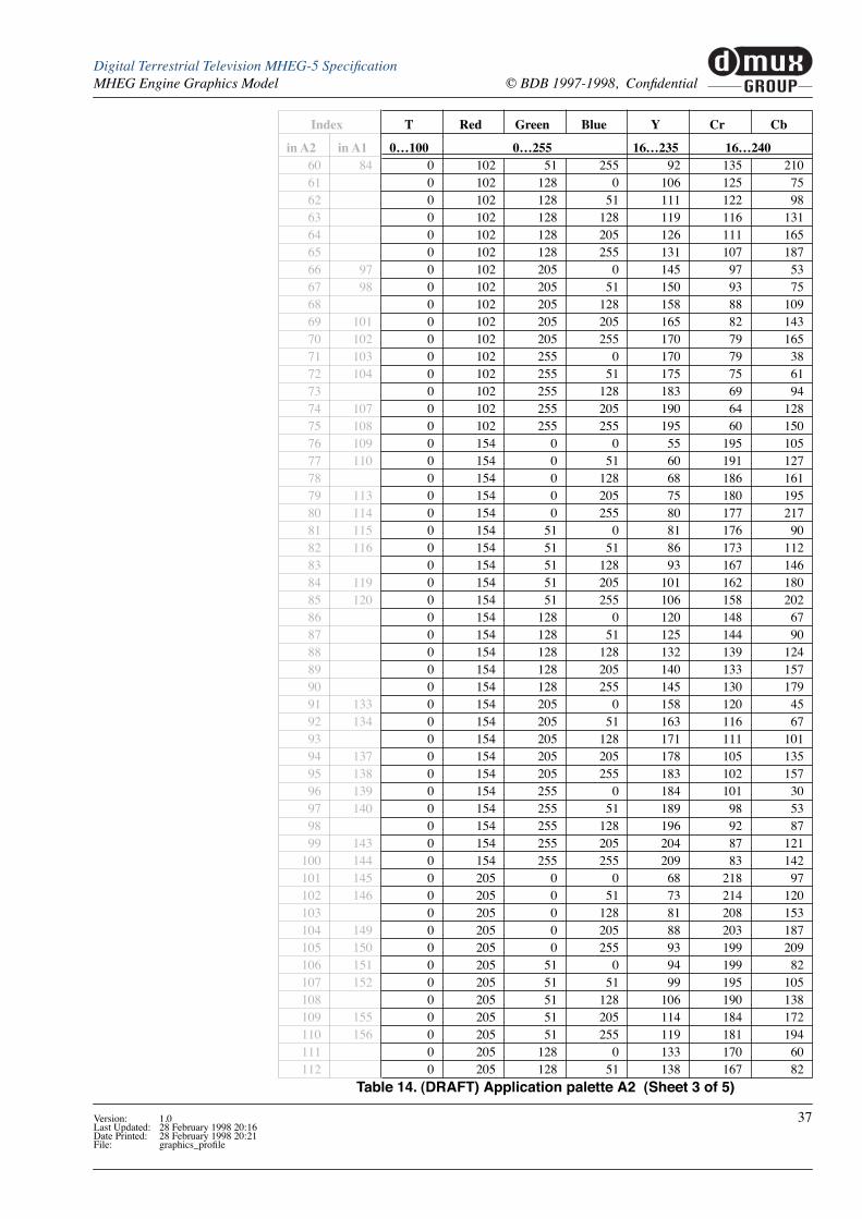
Palette deÞnition The tables 13 and 14 list equivalent RGB and YCrCb deÞnitions for each colour in palettes A1 and A2. The component values in each case are gamma pre-corrected. The rules for the construction of the palettes are given in Table 12. Figure 8 on page 39 illustrates the opaque colours in the two palettes.
a] Plus in also (186, 186, 186) & (224, 224, 224)
Figure 7. Colour Palette modes of operation
M
A2
S
M
A1
No Subtitles
Active
With Subtitles
Active64 colours deÞnable by a DVB Subtitle stream
12 colours deÞnable by the receiver manufacturer
244 Þxed colours deÞned for MHEG-5 application use when no subtitles are active
A1
M
S
180 Þxed colours deÞned for MHEG-5 application use when subtitles are active
A2
Palette T Red Green BlueA1
100%0, 51, 102, 152, 205, 255
A2[a] 0, 51, 102, 152, 205, 255 0, 51, 128, 205, 255A1, A2 50% 0, 128, 255
Table 12. (DRAFT) Palette construction rules
30 Version: 1.0Last Updated: 28 February 1998 20:16Date Printed: 28 February 1998 20:21
File: graphics_proÞle

muxGROUP
dDigital Terrestrial Television MHEG-5 SpeciÞcationMHEG Engine Graphics Model © BDB 1997-1998, ConÞdential
NOTE: The values in these pal-ettes are the subject of on-going research.
Between the two palettes 96 of the opaque colours are common and all of the 50% transpar-ent colours are common. Indexes are listed purely for information, colour indexes are not used in UKEngineProÞle1 applications.
Index T Red Green Blue Y Cr Cb
in A1 in A2 0É100 0É255 16É235 16É2400 0 100 0 0 0 16 128 1281 1 0 0 0 0 16 128 1282 2 0 0 0 51 20 124 1503 0 0 0 102 25 120 1724 0 0 0 154 31 117 1955 4 0 0 0 205 36 113 2186 5 0 0 0 255 40 109 2397 6 0 0 51 0 41 109 1138 7 0 0 51 51 46 105 1359 0 0 51 102 51 101 157
10 0 0 51 154 56 98 18011 9 0 0 51 205 61 94 20312 10 0 0 51 255 66 91 22513 0 0 102 0 67 90 9814 0 0 102 51 72 86 12015 0 0 102 102 77 83 14316 0 0 102 154 82 79 16517 0 0 102 205 87 75 18818 0 0 102 255 92 72 21019 0 0 154 0 93 71 8320 0 0 154 51 98 67 10521 0 0 154 102 103 64 12722 0 0 154 154 108 60 15023 0 0 154 205 113 56 17324 0 0 154 255 118 53 19525 16 0 0 205 0 119 52 6826 17 0 0 205 51 124 48 9027 0 0 205 102 129 45 11328 0 0 205 154 134 41 13529 19 0 0 205 205 139 37 15830 20 0 0 205 255 144 34 18031 21 0 0 255 0 144 34 5332 22 0 0 255 51 149 30 7633 0 0 255 102 154 26 9834 0 0 255 154 159 23 12135 24 0 0 255 205 164 19 14336 25 0 0 255 255 169 16 16537 26 0 51 0 0 29 150 12038 27 0 51 0 51 34 146 14239 0 51 0 102 39 143 16540 0 51 0 154 44 139 18841 29 0 51 0 205 49 135 21042 30 0 51 0 255 54 132 23243 31 0 51 51 0 54 131 10544 32 0 51 51 51 59 128 12845 0 51 51 102 64 124 15046 0 51 51 154 69 120 17347 34 0 51 51 205 74 117 19548 35 0 51 51 255 79 113 217
Table 13. (DRAFT) Application palette A1 (Sheet 1 of 5)
Version: 1.0 31Last Updated: 28 February 1998 20:16Date Printed: 28 February 1998 20:21File: graphics_proÞle

muxGROUP
d Digital Terrestrial Television MHEG-5 SpeciÞcation© BDB 1997-1998, ConÞdential MHEG Engine Graphics Model
49 0 51 102 0 80 112 9050 0 51 102 51 85 109 11351 0 51 102 102 90 105 13552 0 51 102 154 95 101 15853 0 51 102 205 100 98 18054 0 51 102 255 105 94 20255 0 51 154 0 106 93 7556 0 51 154 51 111 90 9857 0 51 154 102 116 86 12058 0 51 154 154 121 82 14359 0 51 154 205 126 79 16560 0 51 154 255 131 75 18761 41 0 51 205 0 132 75 6062 42 0 51 205 51 137 71 8363 0 51 205 102 142 67 10564 0 51 205 154 147 64 12865 44 0 51 205 205 152 60 15066 45 0 51 205 255 157 56 17267 46 0 51 255 0 157 56 4668 47 0 51 255 51 162 52 6869 0 51 255 102 167 49 9170 0 51 255 154 172 45 11371 49 0 51 255 205 177 41 13672 50 0 51 255 255 182 38 15873 51 0 102 0 0 42 172 11274 52 0 102 0 51 47 169 13575 0 102 0 102 52 165 15776 0 102 0 154 57 161 18077 54 0 102 0 205 62 158 20278 55 0 102 0 255 67 154 22479 56 0 102 51 0 67 154 9880 57 0 102 51 51 72 150 12081 0 102 51 102 77 146 14282 0 102 51 154 82 143 16583 59 0 102 51 205 87 139 18884 60 0 102 51 255 92 135 21085 0 102 102 0 93 135 8386 0 102 102 51 98 131 10587 0 102 102 102 103 128 12888 0 102 102 154 108 124 15089 0 102 102 205 113 120 17390 0 102 102 255 118 117 19591 0 102 154 0 119 116 6892 0 102 154 51 124 112 9093 0 102 154 102 129 108 11294 0 102 154 154 134 105 13595 0 102 154 205 139 101 15896 0 102 154 255 144 97 18097 66 0 102 205 0 145 97 5398 67 0 102 205 51 150 93 7599 0 102 205 102 155 90 98
100 0 102 205 154 160 86 120101 69 0 102 205 205 165 82 143
Index T Red Green Blue Y Cr Cb
in A1 in A2 0É100 0É255 16É235 16É240
Table 13. (DRAFT) Application palette A1 (Sheet 2 of 5)
32 Version: 1.0Last Updated: 28 February 1998 20:16Date Printed: 28 February 1998 20:21
File: graphics_proÞle

muxGROUP
dDigital Terrestrial Television MHEG-5 SpeciÞcationMHEG Engine Graphics Model © BDB 1997-1998, ConÞdential
102 70 0 102 205 255 170 79 165103 71 0 102 255 0 170 79 38104 72 0 102 255 51 175 75 61105 0 102 255 102 180 71 83106 0 102 255 154 185 68 106107 74 0 102 255 205 190 64 128108 75 0 102 255 255 195 60 150109 76 0 154 0 0 55 195 105110 77 0 154 0 51 60 191 127111 0 154 0 102 65 188 149112 0 154 0 154 70 184 172113 79 0 154 0 205 75 180 195114 80 0 154 0 255 80 177 217115 81 0 154 51 0 81 176 90116 82 0 154 51 51 86 173 112117 0 154 51 102 91 169 135118 0 154 51 154 96 165 157119 84 0 154 51 205 101 162 180120 85 0 154 51 255 106 158 202121 0 154 102 0 106 158 75122 0 154 102 51 111 154 97123 0 154 102 102 116 150 120124 0 154 102 154 122 147 143125 0 154 102 205 127 143 165126 0 154 102 255 131 139 187127 0 154 154 0 133 138 60128 0 154 154 51 138 135 82129 0 154 154 102 143 131 105130 0 154 154 154 148 128 128131 0 154 154 205 153 124 150132 0 154 154 255 158 120 172133 91 0 154 205 0 158 120 45134 92 0 154 205 51 163 116 67135 0 154 205 102 168 112 90136 0 154 205 154 173 109 113137 94 0 154 205 205 178 105 135138 95 0 154 205 255 183 102 157139 96 0 154 255 0 184 101 30140 97 0 154 255 51 189 98 53141 0 154 255 102 194 94 75142 0 154 255 154 199 90 98143 99 0 154 255 205 204 87 121144 100 0 154 255 255 209 83 142145 101 0 205 0 0 68 218 97146 102 0 205 0 51 73 214 120147 0 205 0 102 78 210 142148 0 205 0 154 83 207 165149 104 0 205 0 205 88 203 187150 105 0 205 0 255 93 199 209151 106 0 205 51 0 94 199 82152 107 0 205 51 51 99 195 105153 0 205 51 102 104 191 127154 0 205 51 154 109 188 150
Index T Red Green Blue Y Cr Cb
in A1 in A2 0É100 0É255 16É235 16É240
Table 13. (DRAFT) Application palette A1 (Sheet 3 of 5)
Version: 1.0 33Last Updated: 28 February 1998 20:16Date Printed: 28 February 1998 20:21File: graphics_proÞle

muxGROUP
d Digital Terrestrial Television MHEG-5 SpeciÞcation© BDB 1997-1998, ConÞdential MHEG Engine Graphics Model
155 109 0 205 51 205 114 184 172156 110 0 205 51 255 119 181 194157 0 205 102 0 120 180 67158 0 205 102 51 125 176 90159 0 205 102 102 130 173 112160 0 205 102 154 135 169 135161 0 205 102 205 140 165 157162 0 205 102 255 145 162 179163 0 205 154 0 146 161 52164 0 205 154 51 151 157 75165 0 205 154 102 156 154 97166 0 205 154 154 161 150 120167 0 205 154 205 166 146 142168 0 205 154 255 171 143 164169 116 0 205 205 0 171 142 37170 117 0 205 205 51 176 138 60171 0 205 205 102 181 135 82172 0 205 205 154 187 131 105173 119 0 205 205 205 192 128 128174 120 0 205 205 255 196 124 149175 121 0 205 255 0 197 124 23176 122 0 205 255 51 202 120 45177 0 205 255 102 207 116 68178 0 205 255 154 212 113 91179 124 0 205 255 205 217 109 113180 125 0 205 255 255 222 106 135181 126 0 255 0 0 81 239 90182 127 0 255 0 51 86 236 112183 0 255 0 102 91 232 135184 0 255 0 154 96 229 157185 129 0 255 0 205 101 225 180186 130 0 255 0 255 106 221 202187 131 0 255 51 0 107 221 75188 132 0 255 51 51 112 217 97189 0 255 51 102 117 213 120190 0 255 51 154 122 210 143191 134 0 255 51 205 127 206 165192 135 0 255 51 255 132 203 187193 0 255 102 0 132 202 60194 0 255 102 51 137 198 82195 0 255 102 102 142 195 105196 0 255 102 154 147 191 128197 0 255 102 205 152 187 150198 0 255 102 255 157 184 172199 0 255 154 0 159 183 45200 0 255 154 51 164 179 67201 0 255 154 102 169 176 90202 0 255 154 154 174 172 113203 0 255 154 205 179 168 135204 0 255 154 255 184 165 157205 141 0 255 205 0 184 164 30206 142 0 255 205 51 189 160 52207 0 255 205 102 194 157 75
Index T Red Green Blue Y Cr Cb
in A1 in A2 0É100 0É255 16É235 16É240
Table 13. (DRAFT) Application palette A1 (Sheet 4 of 5)
34 Version: 1.0Last Updated: 28 February 1998 20:16Date Printed: 28 February 1998 20:21
File: graphics_proÞle

muxGROUP
dDigital Terrestrial Television MHEG-5 SpeciÞcationMHEG Engine Graphics Model © BDB 1997-1998, ConÞdential
208 0 255 205 154 199 153 98209 144 0 255 205 205 204 149 120210 145 0 255 205 255 209 146 142211 146 0 255 255 0 210 146 16212 147 0 255 255 51 215 142 38213 0 255 255 102 220 138 60214 0 255 255 154 225 135 83215 149 0 255 255 205 230 131 106216 150 0 255 255 255 235 128 128217 217 50 0 0 0 16 128 128218 218 50 0 0 128 28 118 184219 219 50 0 0 255 40 109 239220 220 50 0 128 0 80 80 90221 221 50 0 128 128 93 71 146222 222 50 0 128 255 105 62 202223 223 50 0 255 0 144 34 53224 224 50 0 255 128 157 25 110225 225 50 0 255 255 169 16 165226 226 50 128 0 0 48 184 109227 227 50 128 0 128 61 175 165228 228 50 128 0 255 73 166 221229 229 50 128 128 0 113 137 71230 230 50 128 128 128 125 128 128231 231 50 128 128 255 138 118 183232 232 50 128 255 0 177 90 34233 233 50 128 255 128 189 81 91234 234 50 128 255 255 202 72 146235 235 50 255 0 0 81 239 90236 236 50 255 0 128 94 230 146237 237 50 255 0 255 106 221 202238 238 50 255 128 0 146 192 52239 239 50 255 128 128 158 183 109240 240 50 255 128 255 170 174 164241 241 50 255 255 0 210 146 16242 242 50 255 255 128 222 137 72243 243 50 255 255 255 235 128 128244
:255
Reserved for manufacturer use
Index T Red Green Blue Y Cr Cb
in A2 in A1 0É100 0É255 16É235 16É2400 0 100 0 0 0 16 128 1281 1 0 0 0 0 16 128 1282 2 0 0 0 51 20 124 1503 0 0 0 128 28 118 1844 5 0 0 0 205 36 113 2185 6 0 0 0 255 40 109 2396 7 0 0 51 0 41 109 113
Table 14. (DRAFT) Application palette A2 (Sheet 1 of 5)
Index T Red Green Blue Y Cr Cb
in A1 in A2 0É100 0É255 16É235 16É240
Table 13. (DRAFT) Application palette A1 (Sheet 5 of 5)
Version: 1.0 35Last Updated: 28 February 1998 20:16Date Printed: 28 February 1998 20:21File: graphics_proÞle

muxGROUP
d Digital Terrestrial Television MHEG-5 SpeciÞcation© BDB 1997-1998, ConÞdential MHEG Engine Graphics Model
7 8 0 0 51 51 46 105 1358 0 0 51 128 54 100 1699 11 0 0 51 205 61 94 203
10 12 0 0 51 255 66 91 22511 0 0 128 0 80 80 9012 0 0 128 51 85 77 11313 0 0 128 128 93 71 14614 0 0 128 205 100 66 18015 0 0 128 255 105 62 20216 25 0 0 205 0 119 52 6817 26 0 0 205 51 124 48 9018 0 0 205 128 131 43 12419 29 0 0 205 205 139 37 15820 30 0 0 205 255 144 34 18021 31 0 0 255 0 144 34 5322 32 0 0 255 51 149 30 7623 0 0 255 128 157 25 11024 35 0 0 255 205 164 19 14325 36 0 0 255 255 169 16 16526 37 0 51 0 0 29 150 12027 38 0 51 0 51 34 146 14228 0 51 0 128 41 141 17629 41 0 51 0 205 49 135 21030 42 0 51 0 255 54 132 23231 43 0 51 51 0 54 131 10532 44 0 51 51 51 59 128 12833 0 51 51 128 67 122 16134 47 0 51 51 205 74 117 19535 48 0 51 51 255 79 113 21736 0 51 128 0 93 103 8337 0 51 128 51 98 99 10538 0 51 128 128 106 94 13939 0 51 128 205 113 88 17340 0 51 128 255 118 85 19541 61 0 51 205 0 132 75 6042 62 0 51 205 51 137 71 8343 0 51 205 128 144 65 11744 65 0 51 205 205 152 60 15045 66 0 51 205 255 157 56 17246 67 0 51 255 0 157 56 4647 68 0 51 255 51 162 52 6848 0 51 255 128 170 47 10249 71 0 51 255 205 177 41 13650 72 0 51 255 255 182 38 15851 73 0 102 0 0 42 172 11252 74 0 102 0 51 47 169 13553 0 102 0 128 54 163 16954 77 0 102 0 205 62 158 20255 78 0 102 0 255 67 154 22456 79 0 102 51 0 67 154 9857 80 0 102 51 51 72 150 12058 0 102 51 128 80 144 15459 83 0 102 51 205 87 139 188
Index T Red Green Blue Y Cr Cb
in A2 in A1 0É100 0É255 16É235 16É240
Table 14. (DRAFT) Application palette A2 (Sheet 2 of 5)
36 Version: 1.0Last Updated: 28 February 1998 20:16Date Printed: 28 February 1998 20:21
File: graphics_proÞle
muxGROUP
dDigital Terrestrial Television MHEG-5 SpeciÞcationMHEG Engine Graphics Model © BDB 1997-1998, ConÞdential
60 84 0 102 51 255 92 135 21061 0 102 128 0 106 125 7562 0 102 128 51 111 122 9863 0 102 128 128 119 116 13164 0 102 128 205 126 111 16565 0 102 128 255 131 107 18766 97 0 102 205 0 145 97 5367 98 0 102 205 51 150 93 7568 0 102 205 128 158 88 10969 101 0 102 205 205 165 82 14370 102 0 102 205 255 170 79 16571 103 0 102 255 0 170 79 3872 104 0 102 255 51 175 75 6173 0 102 255 128 183 69 9474 107 0 102 255 205 190 64 12875 108 0 102 255 255 195 60 15076 109 0 154 0 0 55 195 10577 110 0 154 0 51 60 191 12778 0 154 0 128 68 186 16179 113 0 154 0 205 75 180 19580 114 0 154 0 255 80 177 21781 115 0 154 51 0 81 176 9082 116 0 154 51 51 86 173 11283 0 154 51 128 93 167 14684 119 0 154 51 205 101 162 18085 120 0 154 51 255 106 158 20286 0 154 128 0 120 148 6787 0 154 128 51 125 144 9088 0 154 128 128 132 139 12489 0 154 128 205 140 133 15790 0 154 128 255 145 130 17991 133 0 154 205 0 158 120 4592 134 0 154 205 51 163 116 6793 0 154 205 128 171 111 10194 137 0 154 205 205 178 105 13595 138 0 154 205 255 183 102 15796 139 0 154 255 0 184 101 3097 140 0 154 255 51 189 98 5398 0 154 255 128 196 92 8799 143 0 154 255 205 204 87 121
100 144 0 154 255 255 209 83 142101 145 0 205 0 0 68 218 97102 146 0 205 0 51 73 214 120103 0 205 0 128 81 208 153104 149 0 205 0 205 88 203 187105 150 0 205 0 255 93 199 209106 151 0 205 51 0 94 199 82107 152 0 205 51 51 99 195 105108 0 205 51 128 106 190 138109 155 0 205 51 205 114 184 172110 156 0 205 51 255 119 181 194111 0 205 128 0 133 170 60112 0 205 128 51 138 167 82
Index T Red Green Blue Y Cr Cb
in A2 in A1 0É100 0É255 16É235 16É240
Table 14. (DRAFT) Application palette A2 (Sheet 3 of 5)
Version: 1.0 37Last Updated: 28 February 1998 20:16Date Printed: 28 February 1998 20:21File: graphics_proÞle

muxGROUP
d Digital Terrestrial Television MHEG-5 SpeciÞcation© BDB 1997-1998, ConÞdential MHEG Engine Graphics Model
113 0 205 128 128 145 161 116114 0 205 128 205 153 156 150115 0 205 128 255 158 152 172116 169 0 205 205 0 171 142 37117 170 0 205 205 51 176 138 60118 0 205 205 128 184 133 94119 173 0 205 205 205 192 128 128120 174 0 205 205 255 196 124 149121 175 0 205 255 0 197 124 23122 176 0 205 255 51 202 120 45123 0 205 255 128 209 115 79124 179 0 205 255 205 217 109 113125 180 0 205 255 255 222 106 135126 181 0 255 0 0 81 239 90127 182 0 255 0 51 86 236 112128 0 255 0 128 94 230 146129 185 0 255 0 205 101 225 180130 186 0 255 0 255 106 221 202131 187 0 255 51 0 107 221 75132 188 0 255 51 51 112 217 97133 0 255 51 128 119 212 131134 191 0 255 51 205 127 206 165135 192 0 255 51 255 132 203 187136 0 255 128 0 146 192 52137 0 255 128 51 151 189 75138 0 255 128 128 158 183 109139 0 255 128 205 166 178 142140 0 255 128 255 170 174 164141 205 0 255 205 0 184 164 30142 206 0 255 205 51 189 160 52143 0 255 205 128 197 155 86144 209 0 255 205 205 204 149 120145 210 0 255 205 255 209 146 142146 211 0 255 255 0 210 146 16147 212 0 255 255 51 215 142 38148 0 255 255 128 222 137 72149 215 0 255 255 205 230 131 106150 216 0 255 255 255 235 128 128151 0 224 224 224 208 128 128152 0 186 186 186 175 128 128153
:216
Reserved for DVB Subtitles
217 217 50 0 0 0 16 128 128218 218 50 0 0 128 28 118 184219 219 50 0 0 255 40 109 239220 220 50 0 128 0 80 80 90221 221 50 0 128 128 93 71 146222 222 50 0 128 255 105 62 202223 223 50 0 255 0 144 34 53224 224 50 0 255 128 157 25 110225 225 50 0 255 255 169 16 165226 226 50 128 0 0 48 184 109
Index T Red Green Blue Y Cr Cb
in A2 in A1 0É100 0É255 16É235 16É240
Table 14. (DRAFT) Application palette A2 (Sheet 4 of 5)
38 Version: 1.0Last Updated: 28 February 1998 20:16Date Printed: 28 February 1998 20:21
File: graphics_proÞle

muxGROUP
dDigital Terrestrial Television MHEG-5 SpeciÞcationMHEG Engine Graphics Model © BDB 1997-1998, ConÞdential
227 227 50 128 0 128 61 175 165228 228 50 128 0 255 73 166 221229 229 50 128 128 0 113 137 71230 230 50 128 128 128 125 128 128231 231 50 128 128 255 138 118 183232 232 50 128 255 0 177 90 34233 233 50 128 255 128 189 81 91234 234 50 128 255 255 202 72 146235 235 50 255 0 0 81 239 90236 236 50 255 0 128 94 230 146237 237 50 255 0 255 106 221 202238 238 50 255 128 0 146 192 52239 239 50 255 128 128 158 183 109240 240 50 255 128 255 170 174 164241 241 50 255 255 0 210 146 16242 242 50 255 255 128 222 137 72243 243 50 255 255 255 235 128 128244
:255
Reserved for manufacturer use
Index T Red Green Blue Y Cr Cb
in A2 in A1 0É100 0É255 16É235 16É240
Table 14. (DRAFT) Application palette A2 (Sheet 5 of 5)
A1 Palette A2 Palette
Figure 8. A1 & A2 Palettes (showing opaque colours only)
Version: 1.0 39Last Updated: 28 February 1998 20:16Date Printed: 28 February 1998 20:21File: graphics_proÞle

muxGROUP
d Digital Terrestrial Television MHEG-5 SpeciÞcation© BDB 1997-1998, ConÞdential MHEG Engine Graphics Model
4.3 Colour Representation
4.3.1 Colour SpaceThe engine is responsible for converting between colour spaces as is required.
Depending on the content type the MHEG engine handles colours in both RGB (colour for buttons, text etc. and PNG graphics) and YCrCb (MPEG stills and DVB subtitles) colour spaces.
This engine speciÞcation doesnÕt comment on the colour representation used in the engineÕs framestore(s).
4.3.2 GammaMPEG video and DVB Subtitles deliver YCrCb data in accordance with ITU-R 601. These signals are gamma pre-corrected. Receivers shall assume that ALL RGB values invoked by MHEG applications are comparably gamma pre-corrected.
Application authors are advised to pre-correct RGB values (such as those in PNG graphics) to be consistent with the pre-correction applied to the MPEG video.
4.3.3 Direct/Absolute coloursDirect/Absolute colour values in MHEG applications shall be expressed as a 4 byte Octet-String constructed as shown in Figure 9.
The Red, Green and Blue code values in the range 0 to 255. The Transparency byte codes values in the range 0 to 255 representing transparency. 0 is opaque.
4.3.4 PNG ModesEngines are required to support ALL of the PNG colour types deÞnes in PNG SpeciÞ-cation Version 1.0 (see Table 15). Engines are responsible for mapping these colours to those used by the engineÕs OSD.
Any combination of PNGs with different colour types may be active at any one time. Simi-larly, engines are responsible for mapping RGB16 direct colour speciÞcations to colours that the OSD can support.
31
0
LSB
Red7
24 23
0Green
7
16 15
0Blue
7
8 7
0Transparency7
0MSB
Figure 9. Absolute colour format
Colour TypeAllowed Bit
DepthsInterpretation
0 1,2,4,8,16 Each pixel is a grayscale sample.2 8,16 Each pixel is an R,G,B triple.3 1,2,4,8 Each pixel is a palette index; PLTE chunk must appear.
4 8,16Each pixel is a grayscale sample, followed by an alpha sample.
6 8,16 Each pixel is an R,G,B triple, followed by an alpha sample.
Table 15. PNG Formats
40 Version: 1.0Last Updated: 28 February 1998 20:16Date Printed: 28 February 1998 20:21
File: graphics_proÞle

muxGROUP
dDigital Terrestrial Television MHEG-5 SpeciÞcationMHEG Engine Graphics Model © BDB 1997-1998, ConÞdential
Where PNG graphics use colours deÞned in the currently active application palette (A1 or A2) these colours shall be reproduced correctly. Other colours shall be reproduced in an implementation dependent way.
Receivers should ignore gAMA (gamma) and cHRM (chromaticity) chunks in PNG Þles.
4.4 Overlapping Visibles
4.4.1 Transparency & Overlapping Visibles
Levels of transparency Receivers are required to implement 3 levels of transparency 0% (opaque), 50% and 100% (completely transparent). Implementation of additional intermediate levels of transparency is optional.
Overlaying visibles When visibles overlap the MHEG-5 rules for Rendering Visibles shall be observed where transparency is 0% or 100% or where semi-transparent pixels are the only visible1 pixels above MPEG video or an MPEG I-frame.
Where intermediate levels of transparency overlay other forms of Visible certain approxima-tions are permitted. If semi-transparent pixels overlay one or more layers of semi-transparent pixels the top most semi-transparent pixel may Òpunch throughÓ to the video or be treated as opaque. However, semi-transparent pixels may not Òpunch throughÓ opaque pixels.
1. I.e. with transparency < 100%.
Perfectly implemented transparent overlay
Acceptably approximated transparent overlay
Figure 10. Approximation of transparency
Red & Green mix
Green punchesthrough transparent
Red
Unacceptably implemented transparent overlay
Green punches through opaque Red
Acceptably approximated transparent overlay
Green overlaytreated as opaque
Version: 1.0 41Last Updated: 28 February 1998 20:16Date Printed: 28 February 1998 20:21File: graphics_proÞle
muxGROUP
d Digital Terrestrial Television MHEG-5 SpeciÞcation© BDB 1997-1998, ConÞdential MHEG Engine Graphics Model
Rendering performance Authors should be aware that the graphics drawing speed may decrease where visibles with an intermediate level of transparency are placed directly over objects other than MPEG video or MPEG I-frames .
Also, visible objects may overlay RTGraphics or the TV serviceÕs DVB Subtitles. However, the RTGraphic/Subtitle rendering speed may degrade and possibly even stop.
4.4.2 RTGraphics & Overlapping VisiblesIn this proÞle receivers always treat an RTGraphics object as being directly above a Video object. This overrides certain aspects of the normal MHEG-5 behaviour for controlling the position of objects within the display stack:
¥ Actions that affect the position of the Video object in the display stack implicitly also affect the position of the RTGraphics object.
¥ Where an RTGraphics object and a Video object are concurrently active actions that should normally affect the stack position of the RTGraphics object shall be ignored.
Where no Video object is concurrently active with an RTGraphics object actions that affect the stack position of the RTGraphics object shall treated as normal. See also ÒDVB Subtitle decoder performanceÓ on page 68.
4.5 LineArt & DynamicLineArtThe following allowances are made to assist receiver implementation. Authors should take account of the implied authoring constraints.
Topic Receiver allowance Authoring guideline
LineStyle attribute Implement ALL line styles as solid
Avoid using dashed or dotted line styles (other line attributes such as width or colour should be used to differentiate line styles)
Filled closed shapes
The receiver behaviour when Þlling certain shapes is not deÞned. These shapes are:¥ concave polygons¥ self-crossing polygons
All other shapes shall be completely Þlled with the colour deÞned by the RefFillColour attribute.
Avoid using Þlled concave polygons and Þlled self crossing polygons. I.e. avoid Þlling shapes like:
If these shapes such as these are required Þlled they may be constructed from primitive elements such as triangles which are guaranteed to Þll in a predictable way.
Self crossing polygons and polylines.
The appearance of pixels at the junction of self crossing lines is not deÞned.
Avoid self crossing lines such as:
Table 16. Limitations on LineArt and DynamicLineArt
42 Version: 1.0Last Updated: 28 February 1998 20:16Date Printed: 28 February 1998 20:21
File: graphics_proÞle
muxGROUP
dDigital Terrestrial Television MHEG-5 SpeciÞcationMHEG Engine Graphics Model © BDB 1997-1998, ConÞdential
4.6 PNG Aspect ratiosPNG bitmaps shall carry a pHYs chunk indicating the pixel aspect ratio of the bitmap. This aspect ratio should be the same as that of the scene containing the bitmap.
The PNG speciÞcation indicates that if the aspect ratio is absent square pixels should be assumed. To avoid overriding this speciÞcation the aspect ratio should be signalled explic-itly.
4.7 Numbers of ObjectsThe minimum number of concurrently active MHEG-5 objects that this proÞle of engine is required to support are:
¥ 1 Video object (an MPEG video stream) OR 1 Bitmap object using MPEG I frame encoding
¥ 1 Audio object (an MPEG audio stream) with source ÔstreamÕ or ÔmemoryÕ
¥ 1 DVB Subtitle stream
See ÒUse of stream decodersÓ on page 111.
The numbers of other presentable object types (e.g. PNG bitmaps, buttons etc.) are only lim-ited by the decoder memory model.
4.8 MPEG stills
4.8.1 File formatThe payload of a Þle delivering an MPEG I frame shall:
¥ be a valid video_sequence() including a sequence_extension()
¥ contain one I frame, i.e. one picture_header(), one picture_coding_extension(), and one picture_data() encoded as an intra coded frame, with picture structure = ÒframeÓ
That is the structure is:
sequence_header()sequence_extension()extension_and_user_data(0)optional group_of_pictures_header() and extension_and_user_data(2) picture_header(picture_coding_type = ÒI frameÓ) picture_coding_extension(picture_structure = Òframe pictureÓ) picture_data()sequence_end_code()
4.8.2 SemanticsAn MPEG-2 video decoder conforming to the same behaviour as the main video decoder (ETR 154 etc.) is used to decode the fragment of data containing the I-frame. The I-frame is scaled in the same way that MPEG video would be scaled. ScaleBitmap( X,Y ) may be used with the same constraints as ScaleVideo( X, Y ). See ÒVideo ScalingÓ on page 68.
So, a bitmap object could have content which is an MPEG I-frame. This frame could be coded as 352x288 and subject to a ScaleBitmap( 360, 288 ) action to provide a 1/4 screen truecolour still picture.
Version: 1.0 43Last Updated: 28 February 1998 20:16Date Printed: 28 February 1998 20:21File: graphics_proÞle

muxGROUP
d Digital Terrestrial Television MHEG-5 SpeciÞcation© BDB 1997-1998, ConÞdential MHEG Engine Graphics Model
4.9 Graphics priorityThe priority to access display resources is (in order of decreasing priority):
¥ Other display using processes (e.g. receiver displays such the navigator, displays pro-duced by the CA system etc.)
¥ Broadcast MHEG-5 applications
¥ Broadcast services (video and subtitling)
When a process with higher priority requests access to the display resources it shall be granted it. This speciÞcation doesnÕt specify in detail the manner in which a receiver pro-vides this resource. However:
¥ When a higher priority process takes the display from a broadcast MHEG-5 application the applications shall be ÒpausedÓ rather than killed.
¥ While the MHEG-5 application does not have access to the display the engine is not required to register real-time events. So, for example, stream or timer events may be missed. See ÒMissed eventsÓ on page 111.
¥ When the display is restored to the application, the engine is responsible for any redraw-ing that may be required.
44 Version: 1.0Last Updated: 28 February 1998 20:16Date Printed: 28 February 1998 20:21
File: graphics_proÞle
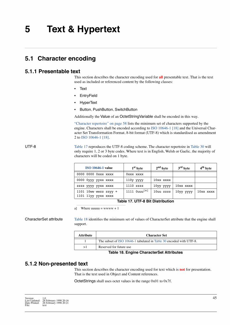
5 Text & Hypertext
5.1 Character encoding
5.1.1 Presentable textThis section describes the character encoding used for all presentable text. That is the text used as included or referenced content by the following classes:
¥ Text
¥ EntryField
¥ HyperText
¥ Button, PushButton, SwitchButton
Additionally the Value of an OctetStringVariable shall be encoded in this way.
ÒCharacter repertoireÓ on page 58 lists the minimum set of characters supported by the engine. Characters shall be encoded according to ISO 10646-1 [18] and the Universal Char-acter Set Transformation Format, 8-bit format (UTF-8) which is standardised as amendment 2 to ISO 10646-1 [18].
UTF-8 Table 17 reproduces the UTF-8 coding scheme. The character repertoire in Table 30 will only require 1, 2 or 3 byte codes. Where text is in English, Welsh or Gaelic, the majority of characters will be coded on 1 byte.
a] Where uuuuu = wwww + 1
CharacterSet attribute Table 18 identiÞes the minimum set of values of CharacterSet attribute that the engine shall support.
5.1.2 Non-presented textThis section describes the character encoding used for text which is not for presentation. That is the text used in Object and Content references.
OctetStrings shall uses octet values in the range 0x01 to 0x7f.
ISO 10646-1 value 1st byte 2nd byte 3rd byte 4th byte
0000 0000 0xxx xxxx 0xxx xxxx
0000 0yyy yyxx xxxx 110y yyyy 10xx xxxx
zzzz yyyy yyxx xxxx 1110 zzzz 10yy yyyy 10xx xxxx
1101 10ww wwzz zzyy +1101 11yy yyxx xxxx
1111 0uuu[a] 10uu zzzz 10yy yyyy 10xx xxxx
Table 17. UTF-8 Bit Distribution
Attribute Character Set
1 The subset of ISO 10646-1 tabulated in Table 30 encoded with UTF-8.
>1 Reserved for future use
Table 18. Engine CharacterSet Attributes
Version: 1.0 45Last Updated: 28 February 1998 20:16Date Printed: 28 February 1998 20:21File: text

muxGROUP
d Digital Terrestrial Television MHEG-5 SpeciÞcation© BDB 1997-1998, ConÞdential Text & Hypertext
5.1.3 Type conversionWhere OctetStrings are converted between from ÒpresentableÓ to Ònon-presentableÓ each character in the ÒpresentableÓ text shall be converted to a single byte by masking with 0x7f.
This type conversion will be applied by the ÒCastToContentRefÓ and ÒCastToObjectRef[a]Ó resident programs (see page 26).
5.2 Fonts
5.2.1 DownloadingReceivers implementing UKEngineProÞle1 shall not support downloadable fonts or the Font class. Application references to fonts shall be direct (i.e. an OctetString representing the name of the font).
5.2.1.1 Future compatibilityThe measures outlined below are designed to improve interoperability with possible future services that make use of downloaded fonts. The preferred approach is the ÒAuthoring solu-tionÓ. However, receivers shall implement the ÒReceiver defensive responseÓ.
Authoring solution Future applications shall be able to determine (via the GetEngineSupport mechanism) the capabilities of the receiver. Using this information applications can adapt their behaviour to avoid problems.
Receiver defensive response
Receivers shall implement the following measures to ensure robust behaviour with any future applications that do use downloaded fonts, or font characteristics that the receiver doesnÕt recognise:
¥ The receiver shall use its in-built font.
¥ If the font style (e.g. bold or plain) is recognised that shall be used, if not plain shall be used in lieu.
¥ If the font size does not match one of those of the in-built font the receiver shall substi-tute the next smaller size provided by the in-built font. If the required font is smaller than the smallest available, then the smallest available in-built size shall be used.
¥ Where there are unrecognised character codes, the receiver shall display character Ô!Õ (0x0021) in that position.
5.2.2 Embedded font
5.2.2.1 The DTG/RNIB font design project
The Project A font design and testing program is being conducted by the DTG and the RNIB with tech-nical support from Bitstream. The objective of this program is to deliver a font with good legibility for use in TV subtitling. The acceptability tests were conducted at the end of 1997 with a view to delivering the Þnished font to the DTG at the end of January 1998. The same font design will be suitable for use in MHEG-5 applications.
Font Characteristics The font is a kerned sans-serif (like Helvetica or Arial) designed to look good on both 4:3 and 16:9 displays. See ÒText on a 4:3 displayÓ on page 51.
IPR This font, ÒUK1Ó, is provided by the RNIB on a royalty free basis for use in digital TV prod-ucts. Manufacturers should contact the RNIB regarding license arrangements if they wish to use the font for another purpose.
46 Version: 1.0Last Updated: 28 February 1998 20:16Date Printed: 28 February 1998 20:21
File: text

muxGROUP
dDigital Terrestrial Television MHEG-5 SpeciÞcationText & Hypertext © BDB 1997-1998, ConÞdential
5.2.2.2 Required sizes and stylesReceivers shall implement at least the DTG/RNIB font ÒUK1Ó in at least the sizes identiÞed in Table 19. This shall be the default font implemented by the engine.
a] The default size and style
5.2.3 Invoking the fontThe font name ÒUK1Ó can be used as a FontName in the application Font attribute or as a text object OriginalFont.
5.2.4 FontAttributesReceivers shall support two font attribute formats, one is DAVIC-like (but verbose), the sec-ond is terser. The short and long forms shall not be mixed within an attribute string.
5.2.4.1 DAVIC-like long formThis string format is <style>.<size>.<linespace>.<letterspace> is carried in an OctetString.1
1. For example, Òbold.28.32.0Ó means bold 28 point text on 32 point line spacing with default letterspace.
Size(points)
Informative NameStyles
Plain Bold
32 Heading / Large subtitle ✓ TBD
28 Subtitle ✓ TBD
24 Body ✓[a] TBD
20 Footnote ✓ TBD
Table 19. ÒUK1Ó sizes and styles
FieldSet of allowed
valuesMeaning
styleÔboldÕ bold text
ÔplainÕ plain text
size Ô20Õ Ô24Õ Ô28Õ Ô32Õ font size in points as decimal integer strings
linespace Ô0Õ ... Ô255Õspace between the baselines of adjacent lines of text in points as decimal integer strings
letterspace Ô-32767Õ ... Ô32767Õincrease in spacing in 1/256 points between consecutive characters expressed as a signed decimal integer string
Table 20. Long form text format parameters
Version: 1.0 47Last Updated: 28 February 1998 20:16Date Printed: 28 February 1998 20:21File: text
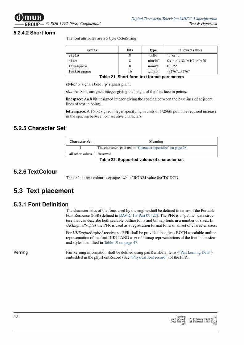
muxGROUP
d Digital Terrestrial Television MHEG-5 SpeciÞcation© BDB 1997-1998, ConÞdential Text & Hypertext
5.2.4.2 Short formThe font attributes are a 5 byte OctetString.
style: ÔbÕ signals bold, ÔpÕ signals plain.
size: An 8 bit unsigned integer giving the height of the font face in points.
linespace: An 8 bit unsigned integer giving the spacing between the baselines of adjacent lines of text in points.
letterspace: A 16 bit signed integer specifying in units of 1/256th point the required increase in the spacing between consecutive characters.
5.2.5 Character Set
5.2.6 TextColourThe default text colour is opaque ÔwhiteÕ RGB24 value 0xCDCDCD.
5.3 Text placement
5.3.1 Font DeÞnitionThe characteristics of the fonts used by the engine shall be deÞned in terms of the Portable Font Resource (PFR) deÞned in DAVIC 1.3 Part 09 [27]. The PFR is a ÒpublicÓ data struc-ture that can describe both scalable outline fonts and bitmap fonts in a number of sizes. In UKEngineProÞle1 the PFR is used as a registration format for a small set of character sizes.
For UKEngineProÞle1 receivers a PFR shall be provided that gives BOTH a scalable outline representation of the font ÒUK1Ó AND a set of bitmap representations of the font in the sizes and styles identiÞed in Table 19 on page 47.
Kerning Pair kerning information shall be deÞned using pairKernData items (ÒPair kerning DataÓ) embedded in the physFontRecord (See ÒPhysical font recordÓ) of the PFR.
syntax bits type allowed values
style 8 bslbf ÔbÕ or ÔpÕ
size 8 uimsbf 0x14, 0x18, 0x1C or 0x20
linespace 8 uimsbf 0...255
letterspace 16 tcimsbf -32767...32767
Table 21. Short form text format parameters
Character Set Meaning
1 The character set listed in ÒCharacter repertoireÓ on page 58
all other values Reserved
Table 22. Supported values of character set
48 Version: 1.0Last Updated: 28 February 1998 20:16Date Printed: 28 February 1998 20:21
File: text

muxGROUP
dDigital Terrestrial Television MHEG-5 SpeciÞcationText & Hypertext © BDB 1997-1998, ConÞdential
5.3.2 ÒlogicalÓ text width rulesTo ensure that text will ßow identically1 on different receivers and authoring stations, regardless of the quality of the character rendering a set of ÒlogicalÓ text width rules are deÞned here. These rules are a simpliÞcation of the rules that might be applied in a typo-graphic rendering system. The objective of these simpliÞcations is to reduce the receiver complexity required to ensure exact correlation of text ßow behaviour.
The ÒlogicalÓ text width shall be used in the following cases:
¥ to determine when to wrap lines of text within a text object
¥ to determine which tab stops text has passed when implementing tab characters
These rules also provide a baseline method for computing character placement when render-ing characters. However, receivers may also use the higher precision methods.
1. I.e. lines and words will break at the same character position.
5.3.2.1 Computing ÒlogicalÓ text widthThe key parameters when calculating the width of a string of N characters are:
¥ Text font size (one of the values in Table 19, ÒÒUK1Ó sizes and styles,Ó on page 47)
¥ charSetWidth (carried by the ÒCharacter RecordÓ)
¥ The metricsResolution (carried by the ÒPhysical font recordÓ)
¥ Any kerning adjustment (See ÒPair kerning DataÓ)
Font sizes Font sizes are expressed as the size of an ÒEmÓ2 in units of ÒpointsÓ3.
2. Broadly speaking this is the minimum distance between the baselines of consecutive lines of text in the given font. If text is 48 point then the Em at that size is 48 points.
3. An archaic typographical unit. Traditionally there were 72.27 points to an inch. Compu-terised systems now use 72 points per inch for simplicity.
Character widths The Physical font record carries a Character Record for each character code. This gives the width of each character relative to the size of an Em in metricsResolution units4.
4. So, if metrics are speciÞed in 1/1000ths of an Em a character with a width of 0.6 Em will have a set width of 600.
Kerning For certain character combinations (a Òkerning pairÓ) a kerning adjustment may also be pro-vided. Typically kerning reduces character spacing for pairs such as AV instead of AV
The Pair kerning Data within the pairKernData extra data items in the Physical font record deÞnes this adjustment. This deÞnes a baseAdjustment (shared by several character pairs) and an adjustment (for a particular character pair). These provide a signed adjustment to the nominal charSetWidth of the Þrst character.
Like charSetWidth kerning adjustments are in terms of metricsResolution units.
Kerning adjustments only apply between characters, not between the start of a line of text and the edge of the text object.
Tracking Tracking (deÞned in the font attribute of the text object See ÒFontAttributesÓ on page 47) allows for an expansion/condensation of the character spacing for all of the characters in a text object.
Version: 1.0 49Last Updated: 28 February 1998 20:16Date Printed: 28 February 1998 20:21File: text

muxGROUP
d Digital Terrestrial Television MHEG-5 SpeciÞcation© BDB 1997-1998, ConÞdential Text & Hypertext
5.3.2.2 Logical text widthThe equation below shows how the width of a string of N characters is computed.
Where in div( A, B ):
¥ B is unsigned and A is signed
and
¥ div( A, B ) = ceil( A / B )
Where '/' is a rational divide and ceil(A) is the Þrst integral number greater than or equal to A. So, the calculations round up when reducing precision and tend to over estimate the width of text.
The width of pixels is 56/45 points, see ÒConverting measurements to display pixelsÓ.
5.3.2.3 Converting measurements to display pixelsThe calculations above are in a high resolution physical coordinate system. These measure-ments need to be converted into the pixel resolution of the display/printing device to allow characters to be rendered.
Computer display systems typically assume a 72 pixel per inch display. So, as each point is 1/72 inch, the horizontal and vertical size of each pixel is 1 point.
Vertical resolution The computer convention is preserved for the vertical dimension of the MHEG display (i.e. each of 576 OSD lines is considered to be 1 point high).
Horizontal resolution Due to the non-square pixel nature of broadcast displays the 1 pixel = 1 point convention cannot be preserved.
From a typographic view point the OSD is 8 inches high. Correspondingly the width of a 4:3 display is 10.66ú inches (768 points) and a 16:9 display 14.22ú inches (1024 points). So, the width of each of the 720 pixels on a 4:3 display is 48/45 points. Similarly, on a 16:9 display the pixels are 64/45 points wide.
logical width of N characterspoints
div N 1Ð( ) track´ 256( , ) div fontsize charSetWidth[i]1
N
å kern[i,i+1]1
N 1Ð
å+è øç ÷æ ö
´ metricsResolution( , )+
=
logical width of N characterspixels div logical width of N characterspoints 45´ 56( , )=
50 Version: 1.0Last Updated: 28 February 1998 20:16Date Printed: 28 February 1998 20:21
File: text

muxGROUP
dDigital Terrestrial Television MHEG-5 SpeciÞcationText & Hypertext © BDB 1997-1998, ConÞdential
A simplifying constraint To simplify the UKEngineProÞle1 ALL receivers shall assume that each of the 720 pix-els has a uniform width of 56/45 points regardless of the scene aspect ratio and display aspect ratio. This corresponds to a 14:9 aspect ratio. So, all text will be subject to moderate aspect ratio distortion. However, broadcasters will be able to predict text ßow without hav-ing to author speciÞcally for each display type. Also, this allows receivers to be implemented with font bitmaps in a single aspect ratio.
5.3.3 Control of text ßow
5.3.3.1 Line breakingIf the TextWrapping attribute of an object is set to ÒtrueÓ the engine shall wrap text within the text box. The behaviour is equivalent to identifying the Þrst word that wonÕt Þt com-pletely within the text box and replacing the space character that precedes the word with a Carriage Return character. I.e. line breaks are only inserted where there are space characters.
If a single word is bigger than the text box, or TextWrapping is set to ÒfalseÓ the engine shall truncate text just before the last character that wonÕt Þt completely within the text box.
The Nth character, after which to break a line, is determine by testing to see if the Òlog-icalÓ width in pixels of the N characters is greater than the distance to the edge of the text box in pixels from the origin of the N characters1.
1. Which will either be the starting edge of the text box or a subsequent tab stop
Text on a 4:3 display
Text on a 16:9 display
Version: 1.0 51Last Updated: 28 February 1998 20:16Date Printed: 28 February 1998 20:21File: text

muxGROUP
d Digital Terrestrial Television MHEG-5 SpeciÞcation© BDB 1997-1998, ConÞdential Text & Hypertext
5.3.3.2 TabulationIn left aligned text (HorizontalJustiÞcation = start) tab stops are deÞned horizontally every 56 points (45 pixels) from the left edge of the text box. ÔHorizontal TabulationÕ advances the origin of the next character to be rendered to the next tab stop in the direction that the text is currently ßowing (the character repertoire in Table 30 only requires left to right text).
Note: a tab ALWAYs advances the rendering of the text. I.e. if the normal origin of the next character to be rendered is on a tab stop, a tab character will advance the rendering to the subsequent tab stop.
5.3.3.3 Line spacingThe line space FontAttribute deÞnes the space between the baselines of consecutive lines of text in points.
LogicalTextWidth[...m]xPos
origin of
origin of
normal origin ofnext character
text box origin (0,0) tab (56,0) tab (112,0)
Figure 11. Effect of horizontal tabulation
Figure 12. Vertical measures
yMin
line space
yMax
baseline
ascent line
52 Version: 1.0Last Updated: 28 February 1998 20:16Date Printed: 28 February 1998 20:21
File: text

muxGROUP
dDigital Terrestrial Television MHEG-5 SpeciÞcationText & Hypertext © BDB 1997-1998, ConÞdential
5.3.3.4 Reproducing JustiÞcation
Vertical - start When VerticalJustiÞcation = start, the baseline of the top line of text shall be yMax below the origin of the text box. See Figure 13.
Horizontal - start When HorizontalJustiÞcation = start (left aligned text) the origin of the Þrst (left most) char-acter shall be at the edge of the enclosing text object. Certain characters (e.g. j) may extend left of the origin (i.e. xPos is negative). Text hanging outside of a text object shall be drawn provided that it lies within the OSD area1. See Figure 13.
1. Where text objects are enclosed by other graphics (e.g. a rectangle) it is the authorÕs responsibility to size the objects if they wish to avoid text affecting an enclosing object.
Vertical - end When VerticalJustiÞcation = end, the baseline of the bottom line of text shall be yMin above the bottom of the text box.
Horizontal - end When HorizontalJustiÞcation = end (right aligned text), the origin of the last (right most) character shall be charSetWidth from the right side of the text box. As with Horizontal - start, certain characters may extend beyond the right hand edge of the text object.
Figure 13. Top-left detail
xPos
-ve yPos
Character cell origin
Text box origin (0,0)
Text box boundary
Baseline
Version: 1.0 53Last Updated: 28 February 1998 20:16Date Printed: 28 February 1998 20:21File: text

muxGROUP
d Digital Terrestrial Television MHEG-5 SpeciÞcation© BDB 1997-1998, ConÞdential Text & Hypertext
5.4 Text ObjectsAll objects using the Text class shall use the character coding described in ÒCharacter encod-ingÓ on page 45 and the fonts described in ÒFontsÓ on page 46.
5.4.1 Text mark-upSee ÒText and HyperText encodingÓ on page 112.
5.4.1.1 White Space CharactersCertain non-printing characters have special meaning. These are identiÞed in Table 23.
5.4.1.2 Format Control Mark-upWithin text object mark-up codes can be used to control the presentation of text. The sequence in Table 24 marks the start of some marked-up text. For each Òstart of mark-upÓ a corresponding Òend of mark-upÓ is deÞned. The byte sequence for the Òend of mark-upÓ is illustrated in Table 25.
UTF8 Value(s) Name Meaning
0x09 Tab See ÒTabulationÓ on page 52
0x0D Carriage Return
Causes the text ßow to break. The origin for the next character to be rendered moves to a new baseline ÒlinespaceÓ below that just rendered. The horizontal position of the next line will depend on the setting of HorizontalJustiÞcation.
0x20 Space
Spaces text by the width deÞned for the space character. When a text object has the TextWrapping attribute set to ÒtrueÓ lines may be broken at a space. See ÒLine breakingÓ on page 51.
0xC2 0xA0Non-breaking
space
Identical spacing characteristics to 0x20 but is not seen as word boundary for deciding a position to break a line of text.(0xC2A0 is the UTF-8 representation of 0x00A0)
Table 23. Special characters
bits value note
start_of_markup 8 0x1B Escape
markup_start_identifier 8 0x40-0x5E Ô@Õ to Ô^Õ
parameters_length 8 N
for( i=0; i<N; i++ ) {
parameter_byte 8 0x00..0xFF
}
Table 24. General format for start of text mark-up
bits value note
end_of_markup 8 0x1B Escape
markup_end_identifier 8 0x60-0x7E ÔÔÕ to Ô~Õ
Table 25. General format for end of text mark-up
54 Version: 1.0Last Updated: 28 February 1998 20:16Date Printed: 28 February 1998 20:21
File: text

muxGROUP
dDigital Terrestrial Television MHEG-5 SpeciÞcationText & Hypertext © BDB 1997-1998, ConÞdential
5.4.1.3 Future compatibilityCompatible extensions to the set of mark-up codes may be deÞned in future proÞles. For each the markup_end_identiÞer will be 32 (0x20) greater than the markup_start_identiÞer. Engines should ignore unrecognised mark-up and should display any text enclosed within an unrecognised mark-up.
5.4.2 Control of text ßow
Required ßow modes Receivers shall implement at least the required set of text ßow modes identiÞed in Table 30.
5.5 HyperText ObjectsIn addition to the mark-up codes identiÞed for Text objects in ÒText mark-upÓ on page 54 HyperText objects can also include the mark-up in Table 28. See ÒText and HyperText encodingÓ on page 112.
5.5.1 HyperText anchorsAfter the application transfers the focus of user interaction to a HyperText object (by using the SetInteractionStatus action) the engine is responsible for managing interaction with the HyperText object.
The OctetString tag_bytes is the ÒtagÓ of the anchor as deÞned by MHEG-5. When the anchor ÒÞresÓ the tag_bytes are returned as the associated data of the AnchorFired event and are placed in the LastAnchorFired internal attribute.
start mark-up end mark-up description
0x1B 0x42 0x00 0x1B 0x42 Applies ÔboldÕ style to the text enclosed
0x1B 0x43 0x04 0xrr 0xgg 0xbb 0xtt
0x1B 0x43Applies colour to the text enclosed. 0xrr speciÞes the red intensity, 0xgg the green, 0xbb the blue and 0xtt the transparency.
Table 26. Text object mark-up codes
Attribute Required Values Optional Values Notes
HorizontalJustiÞcation start, end, centre justiÞed See ÒReproducing JustiÞcationÓ on page 53VerticalJustiÞcation start, end, centre justiÞed
LineOrientation horizontal vertical
StartCorner upper-leftupper-right, lower-left, lower-right
TextWrapping true, falseSee ÒLine breakingÓ on page 51
Table 27. Required set of text ßow modes
start mark-up end mark-up description
0x1B 0x41 0xnn tag_bytes
0x1B 0x41
Associates the OctetString tag_bytes with the Anchor text enclosed between the start mark-up and the end mark-up.0xnn is the length of the tag_bytes OctetString.
Table 28. Additional HyperText mark-up codes
Version: 1.0 55Last Updated: 28 February 1998 20:16Date Printed: 28 February 1998 20:21File: text

muxGROUP
d Digital Terrestrial Television MHEG-5 SpeciÞcation© BDB 1997-1998, ConÞdential Text & Hypertext
The engine is responsible for:
¥ the movement of the user focus amongst the anchors in the HyperText in response to user input
¥ providing feedback to the user as their focus moves
¥ allowing the user to select an anchor
The exact behaviour during this interaction is receiver dependant. However, the following recommendations are made:
¥ links shall be Þred by the user activating the ÒSelectÓ user interface function
¥ interaction with the HyperText object shall be terminated if the user activates the ÒCan-celÓ user interface function
5.6 Rendering TextThis speciÞcation does not deÞne the exact method for rendering characters. The following text is provided Òfor informationÓ. It describes a baseline approach to determining the posi-tions at which to render character bitmaps.
5.6.1 Placing character cellsThe position of each character cell is determined using a resolution measure from the start of text (see Figure 14).
5.6.2 Rendering within character cells
Selecting the font & style The Font ID in the Physical font record names the font and its style. In UKEngineProÞle1 the strings carried by in the Font ID are ÒUK1Ó and ÒUK1 BoldÓ for the plain and bold vari-ants of the font.
Selecting the font size The parameters xppm and yppm in the Bitmap Size Record describe the size of a set of bit-maps in terms of the size of an Em in pixels. In UKEngineProÞle1 yppm shall match the font size requested in the font attributes of the text object. The parameter xppm can be ignored1.
1. xppm would only be relevant if bitmaps optimised for different display aspect ratios were employed.
origin
LogicalTextWidth[a]
LogicalTextWidth[ab]
LogicalTextWidth[abc]
Figure 14. Calculation of character placement
56 Version: 1.0Last Updated: 28 February 1998 20:16Date Printed: 28 February 1998 20:21
File: text

muxGROUP
dDigital Terrestrial Television MHEG-5 SpeciÞcationText & Hypertext © BDB 1997-1998, ConÞdential
Rendering the character When rendering a simple binary bitmap character the position of the character cell is quan-tised from the high resolution measure to the pixel map of the display1. Parameters from the ÒBitmap glyph program stringÓ such as xPos and yPos determine the placement of the char-acter bitmap within the character cell.
The imageData in the Bitmap glyph program string is a compressed pixel map for the char-acter. Each decompressed pixel corresponds exactly to a display pixel.
1. More sophisticated implementations may use antialiasing to implement sub-pixel posi-tioning.
5.6.2.1 Rendering technologyNo restriction is placed on the rendering technology used in a receiver provided that it achieves the deterministic text ßow characteristics described previously.
5.7 Entry FieldsAll receivers shall provide entry Þeld input for the following character repertoires:
xPos
-ve yPos
Character cell origin
Figure 15. Placing a bitmap within the character cell
xPos
yPos= 0
InputType Set of characters Comment
numeric 0 - 9 (UTF-8 coded Unicode 0x30 to 0x39)
alpha
not supportedany
listed
Table 29. Characters supported by EntryFields
Version: 1.0 57Last Updated: 28 February 1998 20:16Date Printed: 28 February 1998 20:21File: text

muxGROUP
d Digital Terrestrial Television MHEG-5 SpeciÞcation© BDB 1997-1998, ConÞdential Text & Hypertext
5.8 Character repertoireThe set of characters identiÞed in Table 30 is under review to see if it is possible to reduce the number of character shapes that receivers have to store. The candidates for possible exclusion are emphasised in the table.
Unicode value G
lyph
Unicode Name For Character
6937
-2
8859
-1 Combining character equivalent
0000 to 0008
Non printing control codes
0009 Horizontal Tabulation 09 09
000A to 000C
000D Carriage Return 0D 0D
000E to 000F
0020 Space 20 20
0021 ! Exclamation Mark 21 21
0022 " Quotation Mark 22 22
0023 # Number Sign 23 23
0024 $ Dollar Sign A4 24
0025 % Percent Sign 25 25
0026 & Ampersand 26 26
0027 ' Apostrophe 27 27
0028 ( Left Parenthesis 28 28
0029 ) Right Parenthesis 29 29
002A * Asterisk 2A 2A
002B + Plus Sign 2B 2B
002C , Comma 2C 2C
002D - Hyphen-minus 2D 2D
002E . Full Stop 2E 2E
002F / Solidus 2F 2F
0030 0 Digit Zero 30 30
0031 1 Digit One 31 31
0032 2 Digit Two 32 32
0033 3 Digit Three 33 33
0034 4 Digit Four 34 34
0035 5 Digit Five 35 35
0036 6 Digit Six 36 36
0037 7 Digit Seven 37 37
0038 8 Digit Eight 38 38
0039 9 Digit Nine 39 39
003A : Colon 3A 3A
003B ; Semicolon 3B 3B
003C < Less-than Sign 3C 3C
003D = Equals Sign 3D 3D
003E > Greater-than Sign 3E 3E
003F ? Question Mark 3F 3F
0040 @ Commercial At 40 40
0041 A Latin Capital Letter A 41 41
0042 B Latin Capital Letter B 42 42
0043 C Latin Capital Letter C 43 43
Table 30. Minimum set of characters supported by the engine (Sheet 1 of 6)
58 Version: 1.0Last Updated: 28 February 1998 20:16Date Printed: 28 February 1998 20:21
File: text

muxGROUP
dDigital Terrestrial Television MHEG-5 SpeciÞcationText & Hypertext © BDB 1997-1998, ConÞdential
0044 D Latin Capital Letter D 44 44
0045 E Latin Capital Letter E 45 45
0046 F Latin Capital Letter F 46 46
0047 G Latin Capital Letter G 47 47
0048 H Latin Capital Letter H 48 48
0049 I Latin Capital Letter I 49 49
004A J Latin Capital Letter J 4A 4A
004B K Latin Capital Letter K 4B 4B
004C L Latin Capital Letter L 4C 4C
004D M Latin Capital Letter M 4D 4D
004E N Latin Capital Letter N 4E 4E
004F O Latin Capital Letter O 4F 4F
0050 P Latin Capital Letter P 50 50
0051 Q Latin Capital Letter Q 51 51
0052 R Latin Capital Letter R 52 52
0053 S Latin Capital Letter S 53 53
0054 T Latin Capital Letter T 54 54
0055 U Latin Capital Letter U 55 55
0056 V Latin Capital Letter V 56 56
0057 W Latin Capital Letter W 57 57
0058 X Latin Capital Letter X 58 58
0059 Y Latin Capital Letter Y 59 59
005A Z Latin Capital Letter Z 5A 5A
005B [ Left Square Bracket 5B 5B
005C \ Reverse Solidus 5C 5C
005D ] Right Square Bracket 5D 5D
005E ^ Circumßex Accent 5E 5E
005F _ Low Line 5F 5F
0060 ` Grave Accent 60 60
0061 a Latin Small Letter A 61 61
0062 b Latin Small Letter B 62 62
0063 c Latin Small Letter C 63 63
0064 d Latin Small Letter D 64 64
0065 e Latin Small Letter E 65 65
0066 f Latin Small Letter F 66 66
0067 g Latin Small Letter G 67 67
0068 h Latin Small Letter H 68 68
0069 i Latin Small Letter I 69 69
006A j Latin Small Letter J 6A 6A
006B k Latin Small Letter K 6B 6B
006C l Latin Small Letter L 6C 6C
006D m Latin Small Letter M 6D 6D
006E n Latin Small Letter N 6E 6E
006F o Latin Small Letter O 6F 6F
0070 p Latin Small Letter P 70 70
0071 q Latin Small Letter Q 71 71
0072 r Latin Small Letter R 72 72
0073 s Latin Small Letter S 73 73
Unicode value G
lyph
Unicode Name For Character
6937
-2
8859
-1 Combining character equivalent
Table 30. Minimum set of characters supported by the engine (Sheet 2 of 6)
Characters highlighted asshown are candidates forexclusion. Service provid-
ers should provide com-ment . Receiver
implementers shouldassume that the full table
is required until notiÞedotherwise.
Version: 1.0 59Last Updated: 28 February 1998 20:16Date Printed: 28 February 1998 20:21File: text
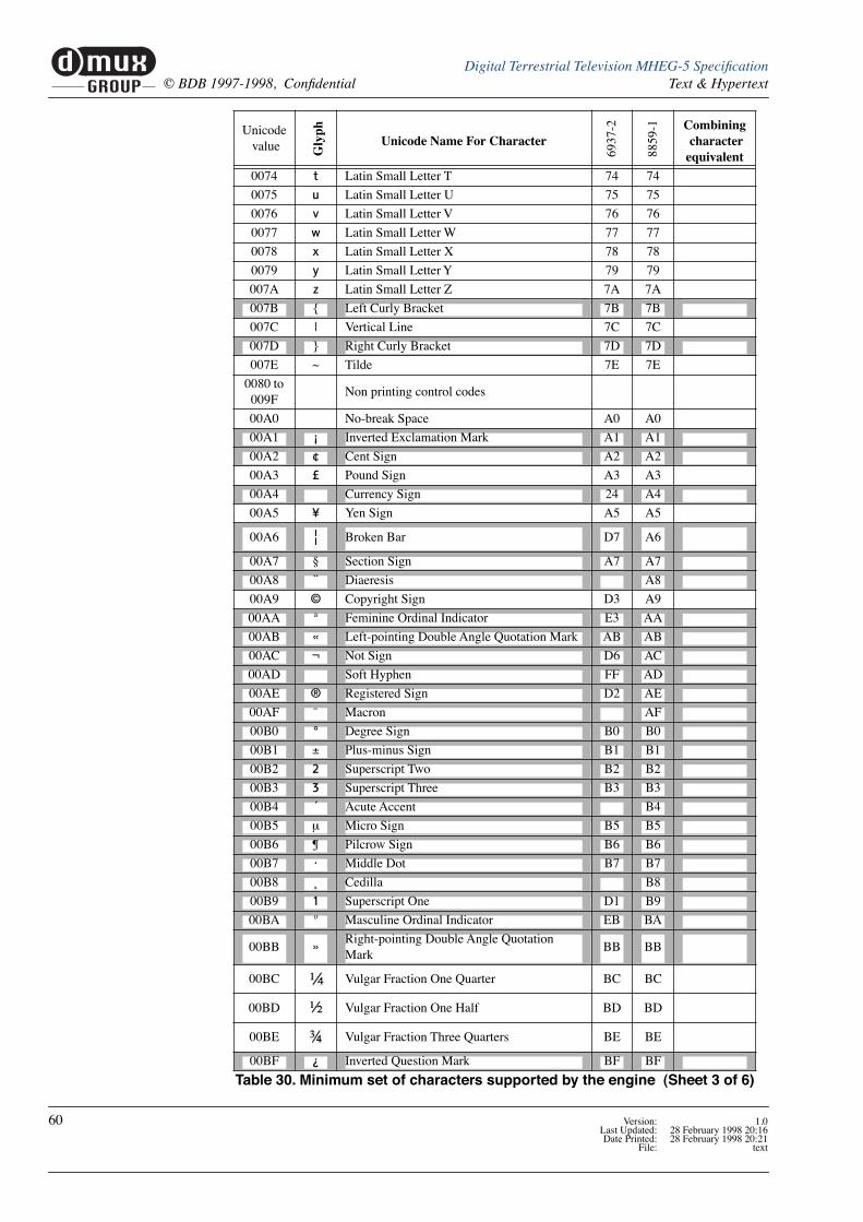
muxGROUP
d Digital Terrestrial Television MHEG-5 SpeciÞcation© BDB 1997-1998, ConÞdential Text & Hypertext
0074 t Latin Small Letter T 74 74
0075 u Latin Small Letter U 75 75
0076 v Latin Small Letter V 76 76
0077 w Latin Small Letter W 77 77
0078 x Latin Small Letter X 78 78
0079 y Latin Small Letter Y 79 79
007A z Latin Small Letter Z 7A 7A
007B { Left Curly Bracket 7B 7B
007C | Vertical Line 7C 7C
007D } Right Curly Bracket 7D 7D
007E ~ Tilde 7E 7E
0080 to 009F
Non printing control codes
00A0 No-break Space A0 A0
00A1 ¡ Inverted Exclamation Mark A1 A1
00A2 ¢ Cent Sign A2 A2
00A3 £ Pound Sign A3 A3
00A4 Û Currency Sign 24 A4
00A5 ¥ Yen Sign A5 A5
00A6 Broken Bar D7 A6
00A7 ¤ Section Sign A7 A7
00A8 ¨ Diaeresis A8
00A9 © Copyright Sign D3 A9
00AA » Feminine Ordinal Indicator E3 AA
00AB « Left-pointing Double Angle Quotation Mark AB AB
00AC Â Not Sign D6 AC
00AD Soft Hyphen FF AD
00AE ® Registered Sign D2 AE
00AF ø Macron AF
00B0 ° Degree Sign B0 B0
00B1 ± Plus-minus Sign B1 B1
00B2 2 Superscript Two B2 B2
00B3 3 Superscript Three B3 B3
00B4 ´ Acute Accent B4
00B5 m Micro Sign B5 B5
00B6 ¦ Pilcrow Sign B6 B6
00B7 · Middle Dot B7 B7
00B8 ü Cedilla B8
00B9 1 Superscript One D1 B9
00BA ¼ Masculine Ordinal Indicator EB BA
00BB »Right-pointing Double Angle Quotation Mark
BB BB
00BC Vulgar Fraction One Quarter BC BC
00BD Vulgar Fraction One Half BD BD
00BE Vulgar Fraction Three Quarters BE BE
00BF ¿ Inverted Question Mark BF BF
Unicode value G
lyph
Unicode Name For Character
6937
-2
8859
-1 Combining character equivalent
Table 30. Minimum set of characters supported by the engine (Sheet 3 of 6)
60 Version: 1.0Last Updated: 28 February 1998 20:16Date Printed: 28 February 1998 20:21
File: text

muxGROUP
dDigital Terrestrial Television MHEG-5 SpeciÞcationText & Hypertext © BDB 1997-1998, ConÞdential
00C0 À Latin Capital Letter A With Grave C0 0041 0300
00C1 Á Latin Capital Letter A With Acute C1 0041 0301
00C2 Â Latin Capital Letter A With Circumßex C2 0041 0302
00C3 Ã Latin Capital Letter A With Tilde C3 0041 0303
00C4 Ä Latin Capital Letter A With Diaeresis C4 0041 0308
00C5 Å Latin Capital Letter A With Ring Above C5 0041 030A
00C6 Æ Latin Capital Letter Ae E1 C6
00C7 Ç Latin Capital Letter C With Cedilla C7 0043 0327
00C8 È Latin Capital Letter E With Grave C8 0045 0300
00C9 É Latin Capital Letter E With Acute C9 0045 0301
00CA Ê Latin Capital Letter E With Circumßex CA 0045 0302
00CB Ë Latin Capital Letter E With Diaeresis CB 0045 0308
00CC Ì Latin Capital Letter I With Grave CC 0049 0300
00CD Í Latin Capital Letter I With Acute CD 0049 0301
00CE Î Latin Capital Letter I With Circumßex CE 0049 0302
00CF Ï Latin Capital Letter I With Diaeresis CF 0049 0308
00D0 Latin Capital Letter Eth E2 D0
00D1 Ñ Latin Capital Letter N With Tilde D1 004E 0303
00D2 Ò Latin Capital Letter O With Grave D2 004F 0300
00D3 Ó Latin Capital Letter O With Acute D3 004F 0301
00D4 Ô Latin Capital Letter O With Circumßex D4 004F 0302
00D5 Õ Latin Capital Letter O With Tilde D5 004F 0303
00D6 Ö Latin Capital Letter O With Diaeresis D6 004F 0308
00D7 ´ Multiplication Sign B4 D7
00D8 Ø Latin Capital Letter O With Stroke E9 D8
00D9 Ù Latin Capital Letter U With Grave D9 0055 0300
00DA Ú Latin Capital Letter U With Acute DA 0055 0301
00DB Û Latin Capital Letter U With Circumßex DB 0055 0302
00DC Ü Latin Capital Letter U With Diaeresis DC 0055 0308
00DD Ÿ Latin Capital Letter Y With Acute DD 0059 0301
00DE Latin Capital Letter Thorn EC DE
00DF ß Latin Small Letter Sharp S FB DF
00E0 à Latin Small Letter A With Grave E0 0061 0300
00E1 á Latin Small Letter A With Acute E1 0061 0301
00E2 â Latin Small Letter A With Circumßex E2 0061 0302
00E3 ã Latin Small Letter A With Tilde E3 0061 0303
00E4 ä Latin Small Letter A With Diaeresis E4 0061 0308
00E5 å Latin Small Letter A With Ring Above E5 0061 030A
00E6 æ Latin Small Letter Ae F1 E6
00E7 ç Latin Small Letter C With Cedilla E7 0063 0327
00E8 è Latin Small Letter E With Grave E8 0065 0300
00E9 é Latin Small Letter E With Acute E9 0065 0301
00EA ê Latin Small Letter E With Circumßex EA 0065 0302
00EB ë Latin Small Letter E With Diaeresis EB 0065 0308
00EC ì Latin Small Letter I With Grave EC 0069 0300
00ED í Latin Small Letter I With Acute ED 0069 0301
00EE î Latin Small Letter I With Circumßex EE 0069 0302
Unicode value G
lyph
Unicode Name For Character
6937
-2
8859
-1 Combining character equivalent
Table 30. Minimum set of characters supported by the engine (Sheet 4 of 6)
Version: 1.0 61Last Updated: 28 February 1998 20:16Date Printed: 28 February 1998 20:21File: text
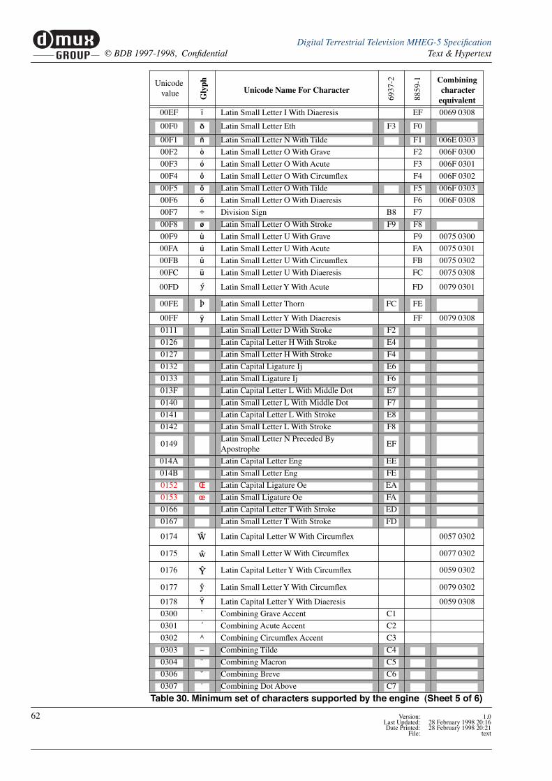
muxGROUP
d Digital Terrestrial Television MHEG-5 SpeciÞcation© BDB 1997-1998, ConÞdential Text & Hypertext
00EF ï Latin Small Letter I With Diaeresis EF 0069 0308
00F0 Latin Small Letter Eth F3 F0
00F1 ñ Latin Small Letter N With Tilde F1 006E 0303
00F2 ò Latin Small Letter O With Grave F2 006F 0300
00F3 ó Latin Small Letter O With Acute F3 006F 0301
00F4 ô Latin Small Letter O With Circumßex F4 006F 0302
00F5 õ Latin Small Letter O With Tilde F5 006F 0303
00F6 ö Latin Small Letter O With Diaeresis F6 006F 0308
00F7 ÷ Division Sign B8 F7
00F8 ø Latin Small Letter O With Stroke F9 F8
00F9 ù Latin Small Letter U With Grave F9 0075 0300
00FA ú Latin Small Letter U With Acute FA 0075 0301
00FB û Latin Small Letter U With Circumßex FB 0075 0302
00FC ü Latin Small Letter U With Diaeresis FC 0075 0308
00FD Latin Small Letter Y With Acute FD 0079 0301
00FE Latin Small Letter Thorn FC FE
00FF ÿ Latin Small Letter Y With Diaeresis FF 0079 0308
0111 Latin Small Letter D With Stroke F2
0126 Latin Capital Letter H With Stroke E4
0127 Latin Small Letter H With Stroke F4
0132 Latin Capital Ligature Ij E6
0133 Latin Small Ligature Ij F6
013F Latin Capital Letter L With Middle Dot E7
0140 Latin Small Letter L With Middle Dot F7
0141 Latin Capital Letter L With Stroke E8
0142 Latin Small Letter L With Stroke F8
0149Latin Small Letter N Preceded By Apostrophe
EF
014A Latin Capital Letter Eng EE
014B Latin Small Letter Eng FE
0152 ΠLatin Capital Ligature Oe EA
0153 œ Latin Small Ligature Oe FA
0166 Latin Capital Letter T With Stroke ED
0167 Latin Small Letter T With Stroke FD
0174 Latin Capital Letter W With Circumßex 0057 0302
0175 Latin Small Letter W With Circumßex 0077 0302
0176 Latin Capital Letter Y With Circumßex 0059 0302
0177 Latin Small Letter Y With Circumßex 0079 0302
0178 Ÿ Latin Capital Letter Y With Diaeresis 0059 0308
0300 ` Combining Grave Accent C1
0301 ´ Combining Acute Accent C2
0302 ^ Combining Circumßex Accent C3
0303 ~ Combining Tilde C4
0304 ø Combining Macron C5
0306 ù Combining Breve C6
0307 ú Combining Dot Above C7
Unicode value G
lyph
Unicode Name For Character
6937
-2
8859
-1 Combining character equivalent
Table 30. Minimum set of characters supported by the engine (Sheet 5 of 6)
62 Version: 1.0Last Updated: 28 February 1998 20:16Date Printed: 28 February 1998 20:21
File: text

muxGROUP
dDigital Terrestrial Television MHEG-5 SpeciÞcationText & Hypertext © BDB 1997-1998, ConÞdential
0308 ¨ Combining Diaeresis C8
030A ˚ Combining Ring Above CA
030B ý Combining Double Acute Accent CD
030C ÿ Combining Caron CF
0327 ü Combining Cedilla CB
0328 þ Combining Ogonek CE
0332 _ Combining Low Line CC
1E80 Latin Capital Letter W With Grave 0057 0300
1E81 Latin Small Letter W With Grave 0077 0300
1E82 Latin Capital Letter W With Acute 0057 0301
1E83 Latin Small Letter W With Acute 0077 0301
1E84 Latin Capital Letter W With Diaeresis 0057 0308
1E85 Latin Small Letter W With Diaeresis 0077 0308
1EF2 Latin Capital Letter Y With Grave 0059 0300
1EF3 Latin Small Letter Y With Grave 0079 0300
2014 — Em Dash D0
2018 ‘ Left Single Quotation Mark A9
2019 ’ Right Single Quotation Mark B9
201C “ Left Double Quotation Mark AA
201D ” Right Double Quotation Mark BA
20A0 Euro-currency Sign
2122 ™ Trade Mark Sign D4
2126 W Ohm Sign E0
212A Kelvin Sign F0
215B Vulgar Fraction One Eighth DC
215C Vulgar Fraction Three Eighths DD
215D Vulgar Fraction Five Eighths DE
215E Vulgar Fraction Seven Eighths DF
2190 Leftwards Arrow AC
2191 Upwards Arrow AD
2192 Rightwards Arrow AE
2193 Downwards Arrow AF
2309 Right Ceiling F5
2669 Quarter Note D5
Unicode value G
lyph
Unicode Name For Character
6937
-2
8859
-1 Combining character equivalent
Table 30. Minimum set of characters supported by the engine (Sheet 6 of 6)
CE
Version: 1.0 63Last Updated: 28 February 1998 20:16Date Printed: 28 February 1998 20:21File: text

muxGROUP
d Digital Terrestrial Television MHEG-5 SpeciÞcation© BDB 1997-1998, ConÞdential Text & Hypertext
64 Version: 1.0Last Updated: 28 February 1998 20:16Date Printed: 28 February 1998 20:21
File: text

6 Receiver Requirements
6.1 IntroductionThis section describes the measures that shall be taken by the receiver to ensure good appli-cation behaviour.
6.2 Auto Start ApplicationWhenever a service that includes an MHEG application as a component is selected the MHEG application shall be launched.
If an MHEG application component is added to a service (e.g. a new event starts that has an associated MHEG application) the MHEG application shall be launched.
HowÕs this done? The receiver looks continuously for the availability of an MHEG application as part of a service. So:
¥ when a service is selected, any MHEG application is launched
¥ if an MHEG application appears in a service that previously didnÕt have an application, the application will be launched.
¥ if an MHEG application Quits the receiver shall try to launch a new application
See ÒApplication IdentiÞcation and BootÓ on page 94.
6.3 Auto Kill ApplicationWhenever the receiver changes channel any executing MHEG application is killed.
I.e. if the user interacts with the receivers navigator functions to change channel the current application will be killed. If the new channel has an application this one will be launched. If the application invokes a channel change (via a resident program), and the channel change is successful, then current application will be killed then replaced by any application associ-ated with the new channel. See ÒKilling ApplicationsÓ on page 28.
Invocation of different video and audio stream objects by an application is not considered a channel change. So, an application can Òpre-viewÓ a service before selecting it.
6.4 Auto Kill Stream DecodersWhenever the receiver changes service all stream decoders are stopped and restarted decoding data from the new service.
I.e. if the user interacts with the receiverÕs navigator functions to change channel the video, audio and subtitle decoders are all stopped and then restarted on the new service.
6.4.1 Stream inheritance by applicationsWhen an MHEG-5 application is launched the Video, Audio and DVB Subtitling stream decoders continue decoding streams from the service containing the application until the application objectÕs preparation phase is complete.
Except where initially active stream objects have been introduced to continue any or all of the Video, Audio and DVB Subtitling stream decoding, the stream decoders will stop when the application object is activated. When an application chooses to play components from
Version: 1.0 65Last Updated: 28 February 1998 20:16Date Printed: 28 February 1998 20:21File: receiver_requirements.fr

muxGROUP
d Digital Terrestrial Television MHEG-5 SpeciÞcation© BDB 1997-1998, ConÞdential Receiver Requirements
the TV service that was active when it launched there shall be no disruption to the stream decoding.
If the user changes service to a service which includes an MHEG application the stream, the decoders will be stopped and restarted with the ÒdefaultÓ streams of the new service in the expectation that the MHEG application will take over control of these streams when it is running.
If, within a service, an MHEG-5 application is launched by another MHEG-5 application, then it has the opportunity to ÒinheritÓ the condition of the stream decoders of the applica-tion that launched it.
Service and component content reference
Applications can be ÒcompiledÓ with explicit service and component references. This is described elsewhere.
Additionally certain generic references are deÞned:
¥ The OctetString Òrec://def_serviceÓ1 may be used as the original content speciÞcation for a Stream object. Òrec://def_serviceÓ means the service currently select by the receiver.
¥ The value Ô-1Õ may be used as the component tag for a Video, Audio or RTGRaphics object. This means the currently selected media component.
For example, an application object might include:
{:Stream 1:OrigContent Òrec://def_serviceÓ:Shared "true":Multiplex ( {:Audio 2 :ComponentTag -1 } )
}
This allows the TV services default audio to continue without disruption. However, Video and Subtitles will stop at the end of application object preparation.
1. See ÒNames within the receiverÓ on page 101.
Component tags for RTGraphics
The MHEG-5 component tag is a 32 bit integer. In all cases the least signiÞcant byte of the tag corresponds to the DVB SI component tag deÞned by the a stream identiÞer descriptor in the PMT of the program.
For an RTGraphics (DVB Subtitle) stream, except when the component tag is -1, the second and third bytes of the MHEG-5 component tag deÞned the least signiÞcant bytes of the required composition_page_id and ancillary_page_id. See Figure 16.
31LSB
0 or -1
24 23
ancillary pge id or -1
16 15
comp. pge id or -1
8 7
component tag or -1
0MSB
Figure 16. Component tag coding for RTGraphics
15 8 7
ancillary page id
0
15 8 7
composition page id
0
66 Version: 1.0Last Updated: 28 February 1998 20:16Date Printed: 28 February 1998 20:21
File: receiver_requirements.fr

muxGROUP
dDigital Terrestrial Television MHEG-5 SpeciÞcationReceiver Requirements © BDB 1997-1998, ConÞdential
6.5 Application Interaction with user Control of DecodersThis section addresses the relationship between user and application control of the stream decoders within the receiver.
6.5.1 Audio Decoder
Controls:
1. This is the userÕs audio stream preference. Typically this will be implemented as an auto-matic receiver response to a stored language preference.
2. This is the MHEG applicationÕs control of the sound level for any application sourced audio. In UKEngineProÞle1 this control is only required to be on/off.
3. This is the MHEG applicationÕs control over whether to replace the programme audio with application sourced audio. See ÒStream inheritance by applicationsÓ on page 65.
4. This is control is operated automatically by the receiver when an application is executing to give the application certain control of the audio.
5. This is the userÕs audio volume control operated by the ÒMuteÓ, ÒVol+Ó, & ÒVol-Ó keys on the remote controler.
6.5.2 Subtitle Decoder
Controls:
1. The ÒSubtitlesÓ key on the remote control or a stored user preference for subtitles control this ÒswitchÓ
2. This is the MHEG applicationÕs control over whether to replace the programme subti-tling with an application selected subtitle stream. See ÒStream inheritance by applica-tionsÓ on page 65.
3. This is control is operated automatically by the receiver when an application is executing to give the application control of the RTGraphics decoder.
Audio Decoder
Control Ô4Õ
Control Ô3Õ
Control Ô1Õ
Application Audiofrom broadcast or
from memory
MPEG Audiochoices inbroadcast
Figure 17. Audio Control - logical model
Control Ô2ÕControl Ô5Õ
RTGraphics Decoder
Control Ô3Õ
Control Ô2Õ
Control Ô1Õ
Application RT Graphicsin broadcast
DVB Subtitlesin broadcast
Figure 18. RT Graphics Control - logical model
Version: 1.0 67Last Updated: 28 February 1998 20:16Date Printed: 28 February 1998 20:21File: receiver_requirements.fr
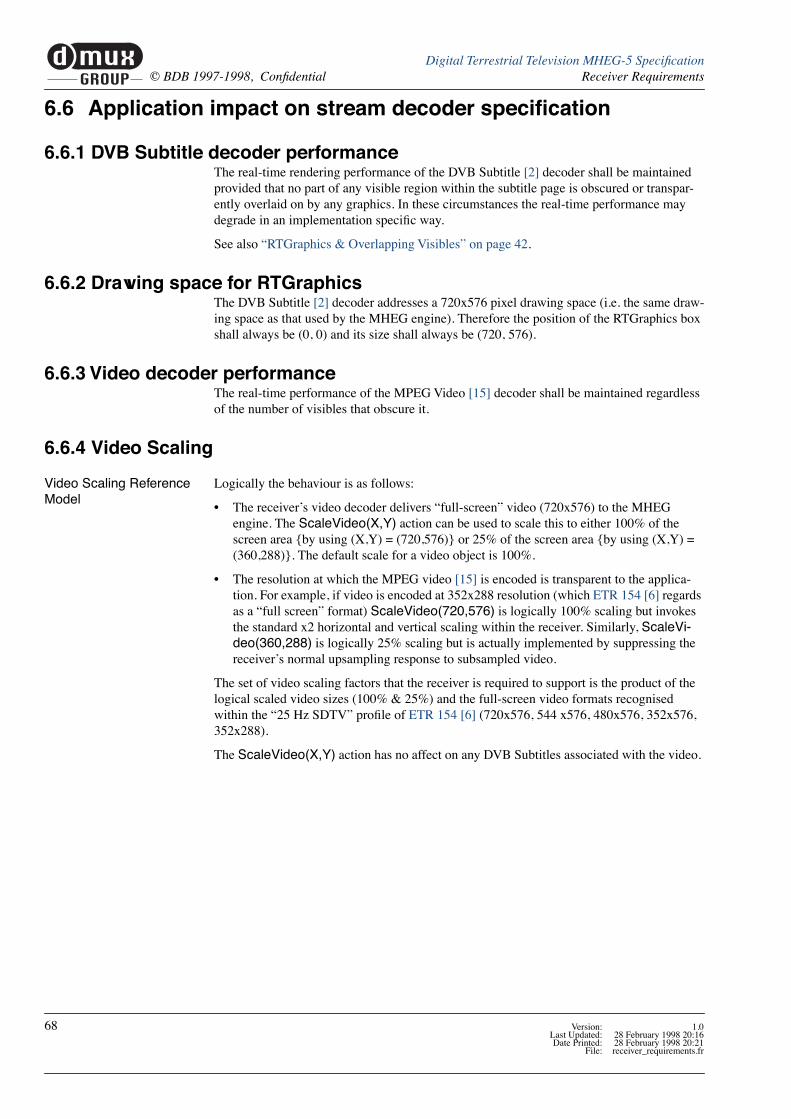
muxGROUP
d Digital Terrestrial Television MHEG-5 SpeciÞcation© BDB 1997-1998, ConÞdential Receiver Requirements
6.6 Application impact on stream decoder speciÞcation
6.6.1 DVB Subtitle decoder performanceThe real-time rendering performance of the DVB Subtitle [2] decoder shall be maintained provided that no part of any visible region within the subtitle page is obscured or transpar-ently overlaid on by any graphics. In these circumstances the real-time performance may degrade in an implementation speciÞc way.
See also ÒRTGraphics & Overlapping VisiblesÓ on page 42.
6.6.2 Drawing space for RTGraphicsThe DVB Subtitle [2] decoder addresses a 720x576 pixel drawing space (i.e. the same draw-ing space as that used by the MHEG engine). Therefore the position of the RTGraphics box shall always be (0, 0) and its size shall always be (720, 576).
6.6.3 Video decoder performanceThe real-time performance of the MPEG Video [15] decoder shall be maintained regardless of the number of visibles that obscure it.
6.6.4 Video Scaling
Video Scaling Reference Model
Logically the behaviour is as follows:
¥ The receiverÕs video decoder delivers Òfull-screenÓ video (720x576) to the MHEG engine. The ScaleVideo(X,Y) action can be used to scale this to either 100% of the screen area {by using (X,Y) = (720,576)} or 25% of the screen area {by using (X,Y) = (360,288)}. The default scale for a video object is 100%.
¥ The resolution at which the MPEG video [15] is encoded is transparent to the applica-tion. For example, if video is encoded at 352x288 resolution (which ETR 154 [6] regards as a Òfull screenÓ format) ScaleVideo(720,576) is logically 100% scaling but invokes the standard x2 horizontal and vertical scaling within the receiver. Similarly, ScaleVi-deo(360,288) is logically 25% scaling but is actually implemented by suppressing the receiverÕs normal upsampling response to subsampled video.
The set of video scaling factors that the receiver is required to support is the product of the logical scaled video sizes (100% & 25%) and the full-screen video formats recognised within the Ò25 Hz SDTVÓ proÞle of ETR 154 [6] (720x576, 544 x576, 480x576, 352x576, 352x288).
The ScaleVideo(X,Y) action has no affect on any DVB Subtitles associated with the video.
68 Version: 1.0Last Updated: 28 February 1998 20:16Date Printed: 28 February 1998 20:21
File: receiver_requirements.fr
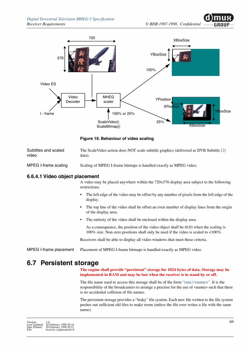
muxGROUP
dDigital Terrestrial Television MHEG-5 SpeciÞcationReceiver Requirements © BDB 1997-1998, ConÞdential
Subtitles and scaled video
The ScaleVideo action does NOT scale subtitle graphics (delivered as DVB Subtitle [2] data).
MPEG I-frame scaling Scaling of MPEG I-frame bitmaps is handled exactly as MPEG video.
6.6.4.1 Video object placementA video may be placed anywhere within the 720x576 display area subject to the following restrictions:
¥ The left edge of the video may be offset by any number of pixels from the left edge of the display.
¥ The top line of the video shall be offset an even number of display lines from the origin of the display area.
¥ The entirety of the video shall be enclosed within the display area.
As a consequence, the position of the video object shall be (0,0) when the scaling is 100% size. Non-zero positions shall only be used if the video is scaled to <100%.
Receivers shall be able to display all video windows that meet these criteria.
MPEG I-frame placement Placement of MPEG I-frame bitmaps is handled exactly as MPEG video.
6.7 Persistent storageThe engine shall provide ÒpersistentÓ storage for 1024 bytes of data. Storage may be implemented in RAM and may be lost when the receiver is in stand-by or off.
The Þle name used to access this storage shall be of the form Òram://<name>Ó. It is the responsibility of the broadcasters to arrange a practise for the use of <name> such that there is no accidental collision of Þle names.
The persistent storage provides a ÒleakyÓ Þle system. Each new Þle written to the Þle system pushes out sufÞcient old Þles to make room (unless the Þle over writes a Þle with the same name).
Video Decoder
Video ES
I - frame
MHEG scaler
ScaleVideo()ScaleBitmap()
576
100% or 25%
720XBoxSize
100%
YBoxSize
XBoxSize
YBoxSize
25%
YPosition
XPosition
Figure 19. Behaviour of video scaling
Version: 1.0 69Last Updated: 28 February 1998 20:16Date Printed: 28 February 1998 20:21File: receiver_requirements.fr

muxGROUP
d Digital Terrestrial Television MHEG-5 SpeciÞcation© BDB 1997-1998, ConÞdential Receiver Requirements
1. Only the data is stored (not type information)
2. The sizes of the variables when stored are deÞned in ÒLimitations on Standard Data-TypesÓ on page 28
3. The set of values is stored in the order they are enumerated in the ASN.1 DER encoding of the StorePersistent InVariables list.
4. The behaviour of ReadPersistent() is undeÞned unless the set of values is enumerated in the same order as the StorePersistent() that created them.
6.7.1 Storage of Þle namesThe <name> part of the Þle name Òram://<name>Ó shall be 8 bytes long. The receiver shall provide storage for at least 32 such Þle names associated with the Òram://Ó persistent store.
See ÒFile names in persistent storageÓ on page 111.
6.7.2 Possible uses of persistent storage (informative)
Start-up Scene reference An application can store the ObjectReference of a speciÞc scene within another application prior to launching that application. The launched application can retrieve the ObjectRefer-ence and TransitionTo the speciÞed scene.
This allows transitions between scenes in two different application. Without this applications could only be launched to start at their root scene.
Return Application reference
An application can store an ObjectReference to itself before launching another application. This allows the launched application to return to the ÒcallingÓ application (although the Spawn action might be a better way of doing this).
Return Application Start-up Scene reference
A scene can store an ObjectReference to itself before launching another application. This allows the ÒcallingÓ application to TransitionTo the ÒcallingÓ scene if it is restarted.
6.8 Reference Decoder ModelA detailed decoder reference will be produced in the future.
Receivers will be expected to implement engines conforming to the reference decoder model with 1 MB of RAM. The reference decoder model will include the storage required to imple-ment the following:
¥ The content required by the currently executing application.
¥ The variables, state etc. used by the currently executing application.
¥ Representation(s) of the application code.
¥ Persistent Þle store and directory structures (See ÒPersistent storageÓ on page 69).
¥ The application identiÞer stack (See ÒApplication StackingÓ on page 71).
¥ Buffers required to receive data from the network (See ÒMapping of objects to data car-ousel modulesÓ on page 89).
¥ Work space required by decoders used solely by the MHEG-5 engine (e.g. PNG decod-ing).
70 Version: 1.0Last Updated: 28 February 1998 20:16Date Printed: 28 February 1998 20:21
File: receiver_requirements.fr

muxGROUP
dDigital Terrestrial Television MHEG-5 SpeciÞcationReceiver Requirements © BDB 1997-1998, ConÞdential
6.9 Application StackingTo support application stacking receivers shall implement an application identiÞer stack capable of holding at least 5 GroupIdentiÞers. See ÒGroupIndentiÞerÓ on page 28. See ÒMapping Rules for GroupIdentiÞerÓ on page 102.
The application identiÞer stack behaves as a simple push down stack. When full, a Spawn action will push the oldest GroupIdentiÞer off the bottom of the stack. If an application ter-minates and the stack is empty then the receiver shall launch the default application for the currently selected service.
The application identiÞer stack shall be reset each time there is a service change.
Version: 1.0 71Last Updated: 28 February 1998 20:16Date Printed: 28 February 1998 20:21File: receiver_requirements.fr

muxGROUP
d Digital Terrestrial Television MHEG-5 SpeciÞcation© BDB 1997-1998, ConÞdential Receiver Requirements
72 Version: 1.0Last Updated: 28 February 1998 20:16Date Printed: 28 February 1998 20:21
File: receiver_requirements.fr
7 Object carousel ProÞle for UK DTT
7.1 IntroductionThe broadcast applications are transmitted using the DSM-CC User-to-User Object Carou-sels.
This speciÞcation is based on the following speciÞcations:
¥ ISO/IEC 13818-1 [14] - MPEG 2 systems
¥ ISO/IEC 13818-6 [17] - DSM-CC
¥ Draft EN 301 192 [5] - DVB speciÞcation for data broadcasting
¥ SI-DAT 382 Rev. 4 [21] - Implementation Guidelines for Databroadcasting
With the constraints and extensions described here.
Work in progress The section ÒApplication IdentiÞcation and BootÓ on page 94 represents the current state of thinking. The proposal is not yet complete and may be modiÞed following discussions within the DVB.
7.2 Object Carousel ProÞleIn the following chapter, the message structures of the Object carousels are introduced with associated additional restrictions. Each section contains a table specifying the restrictions on the usage of the Þelds. The table also indicates the source for these restrictions: the DSM-CC standard, DVB guidelines or a speciÞc restriction for the UK DTT.
For the object carousel messages, also the message syntax is included. In the syntax tables grey shading indicates parts that the broadcaster may put in, but a receiver compliant with this proÞle may ignore.
7.2.1 DSM-CC SectionsAll object carousels messages are transmitted using DSM-CC section format. The DSM-CC Section format is deÞned in chapter 9.2 of the DSM-CC speciÞcation.
The DSM-CC standard provides an option to use either a CRC32 or a checksum for detect-ing bit errors. For UK DTT, we make the following restriction:
The maximum section length is 4096 bytes for all types of sections used in Object Carou-sels. The section overhead is 12 bytes, leaving a maximum of 4084 bytes of payload per sec-tion.
Field Restrictions Source
section_syntax_indicator 1 (indicating the use of the CRC32) UK DTT
Table 31. Restrictions on DSM-CC Section format
Version: 1.0 73Last Updated: 28 February 1998 20:16Date Printed: 28 February 1998 20:21File: ocproÞle.fr

muxGROUP
d Digital Terrestrial Television MHEG-5 SpeciÞcation© BDB 1997-1998, ConÞdential Object carousel ProÞle for UK DTT
7.2.2 Data Carousel
7.2.2.1 GeneralThe deÞnitions in Table 32 apply to both the dsmccDownloadDataHeader and the similar dsmccMessageHeader.
7.2.2.2 DownloadInfoIndicationThe DownloadInfoIndication is a message that describes a set of modules and gives the nec-essary parameters to locate the module and retrieve it.
7.2.2.3 DownloadServerInitiateThe DownloadServerInitiate is used in the case of object carousels to provide the object ref-erence to the service gateway (i.e. root directory) of the object carousel.
Field Restrictions Source
TransactionIdSee ÒAssignment and use of transactionId valuesÓ on page 87
UK DTT
AdaptationLength The adaptionLength shall be 0, indicating no dsmccAdaptationHeader. The adaptation header is not needed in the broadcast scenario.
UK DTT
Table 32. Restrictions on DSM-CC DownloadData and Message headers
Field Restrictions Source
blockSizemaximum size 4066 (max. section payload - DDB-header size (18))The recommended blockSize is 4066.
DSM-CC(UK DTT rec.)
windowSize 0 (not used for Object Carousels) DSM-CC
ackPeriod 0 (not used for Object Carousels) DSM-CC
tCDownloadWindow 0 (not used for Object Carousels) DSM-CC
tCDownloadScenario 0 (not used for Object Carousels) DSM-CC
compatibilityDescriptor(): compatibilityDescriptorLength
0 (no compatibility descriptor for Object Carousels) DSM-CC
PrivateDataLengthThe receiver may ignore the possible contents of the privateData Þeld
DVB
Table 33. Restrictions on the DII
Field Restrictions Source
compatibilityDescriptor(): compatibilityDescriptorLength
0 (no compatibility descriptor for Object Carousels) DSM-CC
privateData Contains the ServiceGatewayInfo structure DSM-CC
serverId Shall be set to 20 bytes with the value of 0xFFDVB / UK DTT
Table 34. Restrictions on DSI
74 Version: 1.0Last Updated: 28 February 1998 20:16Date Printed: 28 February 1998 20:21
File: ocproÞle.fr

muxGROUP
dDigital Terrestrial Television MHEG-5 SpeciÞcationObject carousel ProÞle for UK DTT © BDB 1997-1998, ConÞdential
7.2.2.4 ModuleInfoThe moduleInfo structure is placed in the moduleInfo Þeld of the DownloadInfoIndication of the data carousel. It contains the information needed to locate the module.
Field Restrictions Source
BIOP::ModuleInfo::Taps
The Þrst tap shall have the ÒuseÓ value 0x0017 (BIOP_OBJECT_USE). The id and selector Þelds are not used and the receiver may ignore them. The receiver may ignore possible other taps in the list.
DVB
BIOP::ModuleInfo::UserInfo
The userInfo Þeld contains a loop of descriptors. These are speciÞed in the DVB Data Broadcasting standard. The receiver shall support especially the compressed_module_descriptor (tag 0x09) used to signal that the module is transmitted in compressed form.
DVB / UK DTT
Table 35. Restrictions on the DII moduleInfo Þeld
Syntax bits Type Value CommentBIOP::ModuleInfo() {
moduleTimeOut 32 uimsbf +blockTimeOut 32 uimsbf +minBlockTime 32 uimsbf +taps_count 8 uimsbf N1 ³ 1{
use 16 uimsbf 0x0017 BIOP_OBJECT_USEid 16 uimsbf 0x0000 user privateassocTag 16 uimsbf +selector_length 8 uimsbf 0x00}
for (j=1; j<N1; j++) {
Possible additional taps that may be ignored by receivers.
use 16 uimsbf +id 16 uimsbf +assocTag 16 uimsbf +selector_length 8 uimsbf N2for (j=0; j<N2; j++) {
selector_data 8 uimsbf +}
}
userInfoLength 8 uimsbf N3for (k=0; k<N3; j++) {
userInfo_data 8 uimsbf +}
}
Table 36. BIOP::ModuleInfo syntax
Version: 1.0 75Last Updated: 28 February 1998 20:16Date Printed: 28 February 1998 20:21File: ocproÞle.fr

muxGROUP
d Digital Terrestrial Television MHEG-5 SpeciÞcation© BDB 1997-1998, ConÞdential Object carousel ProÞle for UK DTT
7.2.2.5 ServiceGatewayInfoThe ServiceGatewayInfo structure is carried in the DownloadServerInitiate message and provides the object reference to the Service Gateway object.
Field Restrictions Source
BIOP::ServiceGatewayInfo::downloadTaps
The receiver may ignore the downloadTap list. UK DTT
BIOP::ServiceGatewayInfo::serviceContextList
The receiver may ignore the service context list. UK DTT
BIOP::ServiceGatewayInfo::UserInfo
The user info Þeld contains a loop of descriptors. See ÒApplication IdentiÞcation and BootÓ on page 94.
UK DTT
Table 37. Restrictions on the ServiceGatewayInfo
Syntax bits Type Value CommentServiceGatewayInfo(){
IOP::IOR() + See Table 48 on page 83downloadTaps_count 8 uimsbf N1 software download Tapsfor (i=0; i<N1; i++) {
Tap() 8 uimsbf +}
serviceContextList_count 8 uimsbf N2 serviceContextListfor (i=0; i<N2; i++) {
serviceContextList_data 8 uimsbf +}
userInfoLength 16 uimsbf N3 user infofor (i=0; i<N3; i++) {
userInfo_data 8 uimsbf + See Table 60 on page 98.}
}
Table 38. ServiceGatewayInfo() syntax
76 Version: 1.0Last Updated: 28 February 1998 20:16Date Printed: 28 February 1998 20:21
File: ocproÞle.fr
muxGROUP
dDigital Terrestrial Television MHEG-5 SpeciÞcationObject carousel ProÞle for UK DTT © BDB 1997-1998, ConÞdential
7.2.3 The Object Carousel
7.2.3.1 BIOP Generic Object MessageThe BIOP Generic Object Message is a common structure used by all the BIOP (Broadcast Inter-ORB Protocol) messages.
Field Restrictions Source
MessageHeader::byte_order
0 (indicating big-endian byte order) DVB
MessageSubHeader::objectKey
Maximum length of the key shall be four bytes. DVB
MessageSubHeader::objectKind
The short three-letter aliases shall be used, plus the null-terminator.
DVB
MessageSubHeader::serviceContextList:
The receiver may ignore the service context list UK DTT
Access attributesAccess attributes are not transmitted in object carousels
DSM-CC
Table 39. Restrictions on the BIOP Generic Object Message
Version: 1.0 77Last Updated: 28 February 1998 20:16Date Printed: 28 February 1998 20:21File: ocproÞle.fr

muxGROUP
d Digital Terrestrial Television MHEG-5 SpeciÞcation© BDB 1997-1998, ConÞdential Object carousel ProÞle for UK DTT
7.2.3.2 BIOP FileMessageThe BIOP FileMessage is used for carrying Þle objects.
Field Restrictions Source
MessageSubHeader::ObjectInfo
The Þrst 8 bytes of the ObjectInfo contain the ContentSize attribute. The receiver may skip the possible bytes after the ContentSize attribute.
UK DTT
MessageSubHeader::ServiceContextList
The receiver may skip the possible serviceContextList structures.
UK DTT
Table 40. Restrictions on the BIOP File Message
Syntax bits Type Value CommentBIOP::FileMessage() {
magic 4x8 uimsbf 0x42494F50 ÒBIOPÓbiop_version.major 8 uimsbf 0x01 BIOP major version 1biop_version.minor 8 uimsbf 0x00 BIOP minor version 0byte_order 8 uimsbf 0x00 Big endian byte orderingmessage_type 8 uimsbf 0x00message_size 32 uimsbf *objectKey_length 8 uimsbf N1 <= 4for (i=0; i<N1; i++) {
objectKey_data 8 uimsbf +}
objectKind_length 32 uimsbf 0x00000004objectKind_data 4x8 uimsbf 0x66696C00 ÒÞlÓ type_id aliasobjectInfo_length 16 uimsbf N2DSM::File::ContentSize 64 uimsbf + objectInfofor (i=0; i<N2-8; i++) {
objectInfo_data 8 uimsbf +}
serviceContextList_count 8 uimsbf N3 serviceContextListfor (i=0; i<N3; i++) {
serviceContextList_data 8 uimsbf +}
messageBody_length 32 uimsbf *content_length 32 uimsbf N4for (i=0; i<N4; i++) {
content_byte 8 uimsbf + actual Þle content}
}
Table 41. BIOP::FileMessage syntax
78 Version: 1.0Last Updated: 28 February 1998 20:16Date Printed: 28 February 1998 20:21
File: ocproÞle.fr

muxGROUP
dDigital Terrestrial Television MHEG-5 SpeciÞcationObject carousel ProÞle for UK DTT © BDB 1997-1998, ConÞdential
7.2.3.3 BIOP DirectoryMessageThe BIOP DirectoryMessage is used for carrying the directory objects.
Field Restrictions Source
MessageSubHeader::ObjectInfo
The receiver may skip the possible bytes in the objectInfo Þeld.
UK DTT
MessageSubHeader::ServiceContextList
The receiver may skip the possible serviceContextList structures.
UK DTT
BIOP::NameThe name shall contain exactly one NameComponent.
UK DTT
BIOP::Binding::bindingType
Either ÒncontextÓ (in the case of a Directory object) or ÒnobjectÓ (in the case of a File or a Stream object). Binding type ÒcompositeÓ shall not be used.
DVB
Table 42. Restrictions on the BIOP Directory Message
Syntax bits Type Value CommentBIOP::DirectoryMessage() {
magic 4x8 uimsbf 0x42494F50 ÒBIOPÓbiop_version.major 8 uimsbf 0x01 BIOP major version 1biop_version.minor 8 uimsbf 0x00 BIOP minor version 0byte_order 8 uimsbf 0x00 big endian byte orderingmessage_type 8 uimsbf 0x00message_size 32 uimsbf *objectKey_length 8 uimsbf N1 <= 4for (i=0; i<N1; i++) {
objectKey_data 8 uimsbf +}
objectKind_length 32 uimsbf 0x00000004objectKind_data 4x8 uimsbf 0x64697200 ÒdirÓ type_id aliasobjectInfo_length 16 uimsbf N2 objectInfofor (i=0; i<N2; i++) {
objectInfo_data 8 uimsbf +}
serviceContextList_count 8 uimsbf 0 serviceContextListfor (i=0; i<N3; i++) {
serviceContextList_data 8 uimsbf +}
messageBody_length 32 uimsbf *bindings_count 16 uimsbf N4
Table 43. BIOP::DirectoryMessage syntax (Sheet 1 of 2)
Version: 1.0 79Last Updated: 28 February 1998 20:16Date Printed: 28 February 1998 20:21File: ocproÞle.fr

muxGROUP
d Digital Terrestrial Television MHEG-5 SpeciÞcation© BDB 1997-1998, ConÞdential Object carousel ProÞle for UK DTT
7.2.3.4 BIOP StreamMessageThere are two versions of stream messages. The BIOP StreamMessage is used for carrying the stream objects that donÕt use DSM-CC Stream events. The BIOP StreamEventMessage is used for carrying stream objects that include a stream carrying the DSM-CC Stream events.
for (i=0; i<N4; i++) { BindingBIOP::Name() {
nameComponents_count 8 uimsbf 1for (i=0; i<N5; i++) {
id_length 8 uimsbf N6 NameComponent idfor (j=0; j<N6; j++) {
id_data 8 uimsbf +}
kind_length 8 uimsbf N7 NameComponent kindfor (j=0; j<N7; j++) {
kind_data 8 uimsbf + as type_id (see Table 4-4)}
}
}
BindingType8 uimsbf +
0x01 for nobject0x02 for ncontext
IOP::IOR() + objectRef see Table 48 on page 83objectInfo_length 16 uimsbf 0for (j=0; j<N8; j++) {
objectInfo_byte 8 uimsbf +}
}
}
Syntax bits Type Value Comment
Table 43. BIOP::DirectoryMessage syntax (Sheet 2 of 2)
Field Restrictions Source
MessageSubHeader::ObjectInfo
The ObjectInfo Þeld contains the Stream Info structure and optionally other data after the Stream Info structure. The receiver may ignore the possible other data after the Stream Info structure.
UK DTT
MessageSubHeader::ServiceContextList
The receiver may skip the possible serviceContextList structures.
UK DTT
Table 44. Restrictions on the BIOP Stream Message
Syntax bits Type Value CommentBIOP::StreamMessage() {
magic 4x8 uimsbf 0x42494F50 ÒBIOPÓbiop_version.major 8 uimsbf 0x01 BIOP major version 1biop_version.minor 8 uimsbf 0x00 BIOP minor version 0byte_order 8 uimsbf 0x00 big endian byte orderingmessage_type 8 uimsbf 0x00message_size 32 uimsbf *objectKey_length 8 uimsbf N1 <= 4for (i=0; i<N1; i++) {
objectKey_data 8 uimsbf +
Table 45. BIOP::StreamMessage syntax (Sheet 1 of 2)
80 Version: 1.0Last Updated: 28 February 1998 20:16Date Printed: 28 February 1998 20:21
File: ocproÞle.fr

muxGROUP
dDigital Terrestrial Television MHEG-5 SpeciÞcationObject carousel ProÞle for UK DTT © BDB 1997-1998, ConÞdential
}
objectKind_length 32 uimsbf 0x00000004objectKind_data 8 uimsbf 0x73747200 ÒstrÓ type_id aliasobjectInfo_length 16 uimsbf N6DSM::Stream::Info_T { uimsbf objectInfoaDescription_length 8 uimsbf N2 aDescriptionfor (i=0; i<N2; i++) {
aDescription_bytes 8 uimsbf +}
duration.aSeconds 32 simsbf + AppNPT secondsduration.aMicroSeconds 16 uimsbf + AppNPT micro secondsaudio 8 uimsbf +video 8 uimsbf +data 8 uimsbf +
}
for (i=0; i<N6-(N2+10); i++) {
objectInfo_byte 8 uimsbf +}
serviceContextList_count 8 uimsbf 0 serviceContextListfor (i=0; i<N3; i++) {
serviceContextList_data 8 uimsbf +}
messageBody_length 32 uimsbf *taps_count 8 uimsbf N4for (i=0; i<N4; i++) {
use16 uimsbf +
see Table 4-12 in DVB Guidelines for Data Broadcasting
id 16 uimsbf 0x0000 undeÞnedassocTag 16 uimsbf +selector_length 8 uimsbf 0x00 no selector
}
}
Syntax bits Type Value Comment
Table 45. BIOP::StreamMessage syntax (Sheet 2 of 2)
Syntax bits Type Value CommentBIOP::StreamEventMessage() {
magic 4x8 uimsbf 0x42494F50 ÒBIOPÓversion.major 8 uimsbf 0x01 BIOP major version 1version.minor 8 uimsbf 0x00 BIOP minor version 0byte_order 8 uimsbf 0x00 big endian byte orderingmessage_type 8 uimsbf *message_size 32 uimsbf *objectKey_length 8 uimsbf N1for (i=0; i<N1; i++) {
objectKey_data 8 uimsbf +}
objectKind_length 32 uimsbf 0x00000004objectKind_data 4x8 uimsbf 0x73746500 ÒsteÓ type_id aliasobjectInfo_length 16 uimsbf N6DSM::Stream::Info_T { uimsbfaDescription_length 8 uimsbf N2 aDescriptionfor (i=0; i<N2; i++) {
Table 46. BIOP::StreamEventMessage syntax (Sheet 1 of 2)
Version: 1.0 81Last Updated: 28 February 1998 20:16Date Printed: 28 February 1998 20:21File: ocproÞle.fr

muxGROUP
d Digital Terrestrial Television MHEG-5 SpeciÞcation© BDB 1997-1998, ConÞdential Object carousel ProÞle for UK DTT
7.2.3.5 BIOP Interoperable Object References The Interoperable Object References (IOR) are references to objects and contain the neces-sary information to locate the object. The IOR structure may contain different options to be able to point to objects that can be reached via different types of connections. For this receiver proÞle, the use of IORs is limited to references to objects carried in broadcast object carousels. For object carousels, there are two types of object references: one to be used to
aDescription_bytes 8 uimsbf + see BIOP::StreamMessage()}
duration.aSeconds 32 simsbf + see BIOP::StreamMessage()duration.aMicroSeconds 16 uimsbf + see BIOP::StreamMessage()audio 8 uimsbf + see BIOP::StreamMessage()video 8 uimsbf + see BIOP::StreamMessage()data 8 uimsbf + see BIOP::StreamMessage()
}
DSM::Event::EventList_T {
eventNames_count 16 uimsbf N3for (i=0; i<N3; i++) {
eventName_length 8 uimsbf N4for (j=0; j<N4; j++) {
eventName_data 8 uimsbf + (including zero terminator)}
}
}
for (i=0; i<N6-(N2+10); i++) {
objectInfo_byte 8 uimsbf +}
serviceContextList_count 8 uimsbf N3for (i=0; i<N3; i++) {
serviceContextList_data 8 uimsbf +}
messageBody_length 32 uimsbf *taps_count 8 uimsbf N5for (i=0; i<N5; i++) {
use16 uimsbf +
see Table 4-12 in DVB Guidelines for Data Broadcasting
id 16 uimsbf 0x0000 undeÞnedassocTag 16 uimsbf +selector_length 8 uimsbf 0x00 no selector
}
eventIds_count 8 uimsbf N3 (= eventNames_count)for (i=0; i<N3; i++) {
eventId 16 uimsbf +}
}
Syntax bits Type Value Comment
Table 46. BIOP::StreamEventMessage syntax (Sheet 2 of 2)
82 Version: 1.0Last Updated: 28 February 1998 20:16Date Printed: 28 February 1998 20:21
File: ocproÞle.fr

muxGROUP
dDigital Terrestrial Television MHEG-5 SpeciÞcationObject carousel ProÞle for UK DTT © BDB 1997-1998, ConÞdential
reference objects carried in the same object carousel and one to be used to reference objects in other object carousels.
Field Restrictions Source
IOP::IOR::type_idContains the objectKind of the referenced object. A short three-letter aliases shall be used, plus a null-terminator.
UK DTT
IOP::IOR::taggedProÞleList
There shall be at least 1 taggedProÞle included in an IOR. For objects carried in a broadcast object carousel, the Þrst taggedProÞle shall be either a TAG_BIOP proÞle or a TAG_LITE_OPTIONS. If the Þrst tagged proÞle is some other proÞle, the object is not carried in a broadcast object carousel and the receiver shall ignore the object.
UK DTT
Table 47. Restrictions on the BIOP IOR
Syntax bits Type Value CommentIOP::IOR {
type_id_length 32 uimsbf N1for (i=0; i<N1; i++) {
type_id_byte 8 uimsbf + Short alias type_id (e.g. ÒdirÓ)}
taggedProfiles_count 32 uimsbf N2 ProÞle bodiesprofileId_tag
32 uimsbf +For objects in broadcast carousels: either TAG_BIOP or TAG_LITE_OPTIONS
profile_data_length 32 uimsbf N3for (I=0; i<N3; i++) {
profile_data_byte8 uimsbf
For objects in broadcast carousels: either BIOPProÞleBody or LiteOptionsProÞleBody
}
for (n=0; n<N2-1;n++) { Receiver may ignore other proÞles (2...N1) if present
IOP::taggedProfile() {
profileId_tag 32 uimsbf +profile_data_length 32 uimsbf N3for (i=0; i<N3; i++) {
profile_data_byte 8 uimsbf}
}
}
}
Table 48. IOP::IOR syntax
Version: 1.0 83Last Updated: 28 February 1998 20:16Date Printed: 28 February 1998 20:21File: ocproÞle.fr

muxGROUP
d Digital Terrestrial Television MHEG-5 SpeciÞcation© BDB 1997-1998, ConÞdential Object carousel ProÞle for UK DTT
BiopProÞleBody The BiopProÞleBody is used for references to objects within the same object carousel.
Field Restrictions Source
BiopProÞleBody::byte_order
0 (indicating big-endian byte order) DVB
BiopProÞleBody::LiteOptionComponents
The list shall contain a exactly 1 BiopObjectLocation and exactly 1 DsmConnectionBinder as the Þrst two components in that order. The receiver may ignore possible other components in the list.
UK DTT
DsmConnectionBinder
For objects carried in the broadcast object carousel, the Þrst Tap shall be of type BIOP_DELIVERY_PARA_USE. If there is another type of tap in the Þrst position, the receiver may ignore this object reference, as it is a reference for object accessed using another type of protocol (e.g. for return channel use). The receiver may ignore possible other taps in the list.
UK DTT
BIOP::TapIn the BIOP_DELIVER_PARA_USE tap, the id Þeld is not used and may be ignored by the receiver.
UK DTT
DsmConnectionBinder
For objects carried in the broadcast object carousel, the Þrst Tap shall be of type BIOP_DELIVERY_PARA_USE. If there is another type of tap in the Þrst position, the receiver may ignore this object reference, as it is a reference for object accessed using another type of protocol (e.g. for return channel use). The receiver may ignore possible other taps in the list.
UK DTT
Table 49. Restrictions on the BIOP ProÞle Body
84 Version: 1.0Last Updated: 28 February 1998 20:16Date Printed: 28 February 1998 20:21
File: ocproÞle.fr

muxGROUP
dDigital Terrestrial Television MHEG-5 SpeciÞcationObject carousel ProÞle for UK DTT © BDB 1997-1998, ConÞdential
Syntax bits Type Value CommentBIOPProfileBody {
profileId_tag 32 uimsbf 0x49534F06 TAG_BIOP (BIOP ProÞle Body)profile_data_length 32 uimsbf *profile_data_byte_order 8 uimsbf 0x00 big endian byte orderliteComponents_count 8 uimsbf N1BIOP::ObjectLocation {
componentId_tag 32 uimsbf 0x49534F50 TAG_ObjectLocationcomponent_data_length 8 uimsbf *carouselId 32 uimsbf +moduleId 16 uimsbf +version.major 8 uimsbf 0x01 BIOP protocol major version 1version.minor 8 uimsbf 0x00 BIOP protocol minor version 0objectKey_length 8 uimsbf N2 <= 4for (k=0; k<N2; k++) {
objectKey_data 8 uimsbf +}
}
DSM::ConnBinder {
componentId_tag 32 uimsbf 0x49534F40 TAG_ConnBindercomponent_data_length 8 uimsbf N4taps_count 8 uimsbf N3BIOP::Tap {
use
16 uimsbf 0x0016
For objects carried in the broadcast object carousel: BIOP_DELIVERY_PARA_USE If there is another type of tap in the Þrst position, the receiver may ignore this object reference, as it is a reference for object accessed using another type of protocol (e.g. for return channel use).
Id 16 uimsbf 0x0000 user privateassocTag 16 uimsbf +selector_length 8 uimsbf 0x0Aselector_type 16 uimsbf 0x0001transactionId 32 uimsbf *timeout 32 uimsbf *}
for (n=0; n<N4-18; n++) { The receiver may skip over the possible additional taps
additional_tap_byte 8 uimsbf}
}
for (n=0;n<N6;n++) { N6=N1-2BIOP::LiteOptionComponent{
componentId_tag 32 uimsbf +component_data_length 8 uimsbf N7for (i=0; i<N7; i++) {
component_data_byte 8 uimsbf}
}
}
}
Table 50. BIOP ProÞle Body syntax
Version: 1.0 85Last Updated: 28 February 1998 20:16Date Printed: 28 February 1998 20:21File: ocproÞle.fr

muxGROUP
d Digital Terrestrial Television MHEG-5 SpeciÞcation© BDB 1997-1998, ConÞdential Object carousel ProÞle for UK DTT
Lite Options ProÞle Body The LiteOptionsProÞleBody is used for making links to objects carried in other object car-ousels. For this receiver proÞle, the use of the LiteOptionsProÞleBody is limited to be used only within the same transport stream. Thus, the use of the object carousel will not require tuning to a new transport stream.
Field Restrictions Source
LiteOptionsProÞleBody::proÞle_data_byte_order
0 (indicating big-endian byte order) DVB
LiteOptionsProÞleBody::LiteOptionComponents
The list shall contain a ServiceLocation component as the Þrst component. The receiver may ignore possible other components in the list.
UK DTT
Dsm::ServiceLocation
For objects carried in the broadcast object carousel, the service domain NSAP address shall follow the Carousel NSAP address format. If there is another type of NSAP address, the receiver may ignore this object reference, as it is a reference for object accessed using another type of protocol (e.g. for return channel use). The carousel NSAP address shall point to an object carousel in the same transport stream. If the NSAP address points to another transport stream, the receiver may ignore the object reference.
UK DTT
Dsm::ServiceLocation::InitialContext
The receiver may ignore the initial context UK DTT
Table 51. Restrictions on the Lite Options ProÞle Body
Syntax bits Type Value CommentLiteOptionsProfileBody {
profileId_tag32 uimsbf 0x49534F05
TAG_LITE_OPTIONS (Lite Options ProÞle Body)
profile_data_length 32 uimsbf *profile_data_byte_order 8 uimsbf 0x00 big endian byte ordercomponent_count 8 uimsbf N1DSM::ServiceLocation {
componentId_tag 32 uimsbf 0x49534F46 TAG_ServiceLocationcomponent_data_length 32 uimsbf *serviceDomain_length 8 uimsbf 0x14 Length of carousel NSAP addressserviceDomain_data()
160 uimsbf +DVBcarouselNSAPaddress, see Table 4-8 in DVB Guidelines for Data Broadcasting
CosNaming::Name() { pathNamenameComponents_count 32 uimsbf N2for (i=0; i<N2; i++) {
id_length 32 uimsbf N3 NameComponent idfor (j=0; j<N3 j++) {
id_data 8 uimsbf +}
kind_length 32 uimsbf N4 NameComponent kindfor (j=0; j<N4 j++) {
kind_data8 uimsbf +
as type_id (see Table 4-4 in DVB Guidelines for Data Broadcasting)
}
}
Table 52. Syntax of Options ProÞle Body with ServiceLocation component. (Sheet 1 of 2)
86 Version: 1.0Last Updated: 28 February 1998 20:16Date Printed: 28 February 1998 20:21
File: ocproÞle.fr
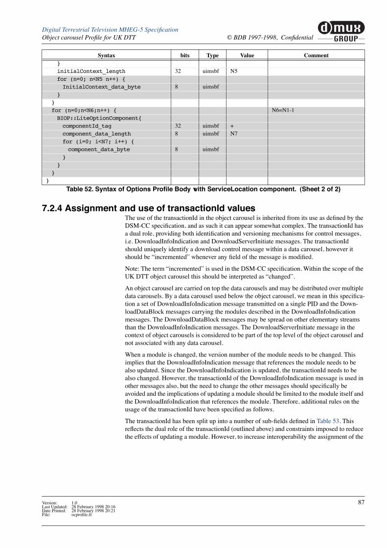
muxGROUP
dDigital Terrestrial Television MHEG-5 SpeciÞcationObject carousel ProÞle for UK DTT © BDB 1997-1998, ConÞdential
7.2.4 Assignment and use of transactionId valuesThe use of the transactionId in the object carousel is inherited from its use as deÞned by the DSM-CC speciÞcation, and as such it can appear somewhat complex. The transactionId has a dual role, providing both identiÞcation and versioning mechanisms for control messages, i.e. DownloadInfoIndication and DownloadServerInitiate messages. The transactionId should uniquely identify a download control message within a data carousel, however it should be ÒincrementedÓ whenever any Þeld of the message is modiÞed.
Note: The term ÒincrementedÓ is used in the DSM-CC speciÞcation. Within the scope of the UK DTT object carousel this should be interpreted as ÒchangedÓ.
An object carousel are carried on top the data carousels and may be distributed over multiple data carousels. By a data carousel used below the object carousel, we mean in this speciÞca-tion a set of DownloadInfoIndication message transmitted on a single PID and the Down-loadDataBlock messages carrying the modules described in the DownloadInfoIndication messages. The DownloadDataBlock messages may be spread on other elementary streams than the DownloadInfoIndication messages. The DownloadServerInitiate message in the context of object carousels is considered to be part of the top level of the object carousel and not associated with any data carousel.
When a module is changed, the version number of the module needs to be changed. This implies that the DownloadInfoIndication message that references the module needs to be also updated. Since the DownloadInfoIndication is updated, the transactionId needs to be also changed. However, the transactionId of the DownloadInfoIndication message is used in other messages also, but the need to change the other messages should speciÞcally be avoided and the implications of updating a module should be limited to the module itself and the DownloadInfoIndication that references the module. Therefore, additional rules on the usage of the transactionId have been speciÞed as follows.
The transactionId has been split up into a number of sub-Þelds deÞned in Table 53. This reßects the dual role of the transactionId (outlined above) and constraints imposed to reduce the effects of updating a module. However, to increase interoperability the assignment of the
}
initialContext_length 32 uimsbf N5for (n=0; n<N5 n++) {
InitialContext_data_byte 8 uimsbf}
}
for (n=0;n<N6;n++) { N6=N1-1BIOP::LiteOptionComponent{
componentId_tag 32 uimsbf +component_data_length 8 uimsbf N7for (i=0; i<N7; i++) {
component_data_byte 8 uimsbf}
}
}
}
Syntax bits Type Value Comment
Table 52. Syntax of Options ProÞle Body with ServiceLocation component. (Sheet 2 of 2)
Version: 1.0 87Last Updated: 28 February 1998 20:16Date Printed: 28 February 1998 20:21File: ocproÞle.fr

muxGROUP
d Digital Terrestrial Television MHEG-5 SpeciÞcation© BDB 1997-1998, ConÞdential Object carousel ProÞle for UK DTT
transactionId has been designed to be independent of the expected Þltering in target receiv-ers.
Due to the role of the transactionId as a versioning mechanism, any change to a control mes-sage will cause the transactionId of that control message to be incremented. Any change to a Module will necessitate incrementing its moduleVersion Þeld. This change must be reßected in the corresponding Þeld in the description of the Module in the DownloadInfoIndication message(s) that describes it. Since a Þeld in the DownloadInfoIndication message is changed its transactionId must be incremented to indicate a new version of the message. Also, any change in the DownloadServerInitiate message implies that its transactionId must also be incremented. However, when the transactionId is divided into subÞelds as speciÞed above, updating a message will change only the Version part of the transactionId while the IdentiÞcation part remains the same.
Since the transactionId is used also for identifying the messages when referencing the mes-sages in other structures, it is very desirable that these referenced would not need to be updated every time the control message is update. Therefore the following rule shall be applied when locating the messages based on the references:
When locating a message based on the transactionId value used for referencing the mes-sage, only the IdentiÞcation part (bits 1...15) shall be matched.
Using this rule, the implications of updating a module can be limited to the module itself and the DownloadInfoIndication message describing the module. Also, this implies that if a receiver wants to Þnd out if a particular module that it has retrieved earlier has changed, it needs to Þlter the DownloadInfoIndication message that described that module and check if it has been changed.
Bits Value Sub-Þeld Description
0 User-deÞned Updated ßagThis must be toggled every time the control message is updated
1-15 User-deÞned IdentiÞcation
This must and can only be all zeros for the DownloadServerInitiate message. All other control messages must have one or more non-zero bit(s).
16-29 User-deÞned VersionThis must be incremented/changed every time the control message is updated.
30-31Bit 30 - zeroBit 31 - non-zero
Originator
This is deÞned in the DSM-CC speciÞcation [17] as 0x02 if the transactionId has been assigned by the network - in a broadcast scenario this is implicit.
Table 53. Sub-Þelds of the transactionId
88 Version: 1.0Last Updated: 28 February 1998 20:16Date Printed: 28 February 1998 20:21
File: ocproÞle.fr

muxGROUP
dDigital Terrestrial Television MHEG-5 SpeciÞcationObject carousel ProÞle for UK DTT © BDB 1997-1998, ConÞdential
7.2.5 Mapping of objects to data carousel modulesThe DSM-CC Object Carousels allow one or more objects to be carried in one module of the data carousel. In order to optimize the performance and memory requirements two addi-tional requirements are speciÞed:
¥ When mapping objects to modules of a data carousel, only closely related objects (e.g. objects of one MHEG scene) should be put into one module. Objects that are not closely related should not be put into the same module. If in the process of retrieving an object from the carousel a receiver acquires a module containing multiple objects, it should attempt to cache these since the expectation should be that the other objects are related to the object requested and probably will be needed soon.
¥ The size of a module that contains multiple objects should not exceed [64] kB when decompressed1. For modules containing only a single object, there is obviously no limit for the size (except what is determined by the memory in the receivers and the size of the length Þelds).
1. I.e. when the Þle has been decompressed from the Þle transport but before the content decoding has started.
7.2.6 Compression of modulesThe modules may be transmitted either in uncompressed or compressed form. If the module is transmitted in compressed form, this is signalled by including the compressed_module_descriptor in the userInfo Þeld of the moduleInfo in the DownloadIn-foIndication message.
Presence of the compressed_module_descriptor indicates that the data in the module has the ÒzlibÓ structure as deÞned in RFC1950.
Table 54 shows the syntax of the compressed_module_descriptor:
Presence of the compressed_module_descriptor indicates that the data in the module has the ÒzlibÓ structure as deÞned in RFC 1950. Table 55 shows the syntax of the ZLIB structure.
The receiver shall support the Deßate compression algorithm as speciÞed in RFC 1951. This is signalled setting the most signiÞcant nibble of the compression_method to 0x8 (i.e.
No. of bytes
Mnemonic Value
compressed_module_descriptor(){
descriptor_tag 1 uimsbf 0x09descriptor_length 1 uimsbforiginal_size 4 uimsbf
}
Table 54. compressed_module_descriptor
No. of bytes
Value
zlib structure(){
compression_method 1flags_check 1compressed_data ncheck value 4
}
Table 55. zlib structure
Version: 1.0 89Last Updated: 28 February 1998 20:16Date Printed: 28 February 1998 20:21File: ocproÞle.fr
muxGROUP
d Digital Terrestrial Television MHEG-5 SpeciÞcation© BDB 1997-1998, ConÞdential Object carousel ProÞle for UK DTT
compression_method is 1000xxxx). The receiver is not required to support other compres-sion algorithms.
7.3 Tag Mapping
7.3.1 MHEG-5 ComponentTags to DSM-CC association_tagsThe MHEG-5 ComponentTag is mapped to the least signiÞcant byte of the association_tag as deÞned by ISO/IEC 13818-6 [17]. The most signiÞcant byte of the association_tag may take any value (0xXX). The value encoded in the least signiÞcant byte (LSB) of the association_tag shall be equal to the MHEG-5 ComponentTag value. In addition, the value of the component_tag deÞned in the stream_identiÞer_descriptor speciÞed by DVB shall also take the same value as the MHEG-5 ComponentTag. A stream_identiÞer_descriptor in the descriptor loop of a PID is equivalent with an association_tag_descriptor for that PID with an association_tag value of MSB=0xXX and LSB=<component_tag> and a use value of 0x0100.
7.3.2 DSM-CC association_tags to DVB component_tagsThe component_tag in a PMTÕs stream_identiÞer_descriptor is used to relate SI service component information with an elementary stream without directly referring to a PID value. Likewise, the association_tag in the DSM-CCÕs association_tag_descriptor is used to relate (part of) an object carousel with an elementary stream without directly referencing a PID value. To avoid duplicating component_- and association_tags, the DVB speciÞcation deÞnes a mapping between the two. The mapping of the 8-bit component_tag to the 16-bit association_tag is as follows: (ref. paragraph 8.3)
Òit is assumed that in the absence of an association_tag_descriptor, the component_tag Þeld of the stream_identiÞer_descriptor is the Least SigniÞcant Byte of the referenced association_tag value.Ó
Similarly, the DVB Guideline is: (ref. 4.7.7.3)
ÒA stream_identiÞer_descriptor in the descriptor loop of a PID shall be equivalent with an association_tag_descriptor for that PID with an association_tag value of LSB=<component_tag> and a use value of 0x0100.Ó
Note that this deÞnition provides the ßexibility to distribute the object carousel over multiple elementary streams and over multiple services while still allowing the use of the same component_tag value in the different PMTs.
See also ÒComponent tags for RTGraphicsÓ on page 66.
90 Version: 1.0Last Updated: 28 February 1998 20:16Date Printed: 28 February 1998 20:21
File: ocproÞle.fr

muxGROUP
dDigital Terrestrial Television MHEG-5 SpeciÞcationObject carousel ProÞle for UK DTT © BDB 1997-1998, ConÞdential
The following Þgure illustrates the decision tree for identifying the elementary stream(s) by which the object carousel is distributed:
In UK DTT, the stream_identiÞer_descriptor shall always be used for assigning a component_tag for the elementary streams. Use of association_tag_descriptors is not required. If the association_tag_descriptor is optionally used, a stream_identiÞer_descriptor shall still be present and the tag values shall be set consistently in each descriptor. This restriction simpliÞes the decision tree above so that the second decision can be skipped.
association_tag in(any of the)
deferred_association_descriptors?
association_tag in(any of the)
association_tag_descriptors in the elementary stream loop
?
LSB of association_tagin (any of the)
stream_identiÞer_descriptors in the elementary stream loop
?
association_tag
No
No
No
Error
Go to other PMT
Match
Match
Figure 20. Object Carousel ES identiÞcation decision tree
Yes
Yes
Yes
Version: 1.0 91Last Updated: 28 February 1998 20:16Date Printed: 28 February 1998 20:21File: ocproÞle.fr

muxGROUP
d Digital Terrestrial Television MHEG-5 SpeciÞcation© BDB 1997-1998, ConÞdential Object carousel ProÞle for UK DTT
7.4 Example of an Object CarouselThe Þgure below illustrates an object carousel that is distributed over three elementary streams belonging to the same service.
The DownloadServerInitiate (DSI) message is carried on the Þrst elementary stream. It con-tains the object reference that points to the service gateway. The tap with the BIOP_DELIVERY_PARA_USE points to a DownloadInfoIndication (DII) message that provides the information about the module and the location where the module is being broadcasted. In the example, the service gateway object is in the module number 1 that is carried on the second elementary stream (indicated by a BIOP_OBJECT_USE tap structure in the DII message).
The Service Gateway object is a root directory that, in this example, references three subdi-rectories. Taps with BIOP_DELIVERY_PARA_USE are used in the object references of the subdirectories to provide links to the modules via the DownloadInfoIndication (DII) mes-sage. The two Þrst subdirectories Òdir1Ó and Òdir2Ó are referenced in the DII message that is carried in the Þrst elementary stream. The third subdirectory is referenced in the DII mes-sage carried in the third elementary stream.
In this example, the two Þrst elementary streams carry the messages of one logical data car-ousel while the third elementary stream carries the messages of another logical data carou-sel. All these belong to the same object carousel. In the example, the third elementary stream contains the objects in the Òdir3Ó subdirectory and the objects in the Òdir1Ó and Òdir2Ó subdi-rectories are distributed over the Þrst and second elementary stream.
It is important to note that the third elementary stream may originate from a completely sep-arate source than the Þrst two elementary streams. The directory hierarchy and objects con-tained in the third elementary stream are ÒmountedÓ in the root directory by providing the Òdir3Ó directory entry with the appropriate location information.
DSI mod 2 mod 3DII
mod 4 mod 5 mod 6mod 1
DII mod 2 mod 4mod 1 mod 3
DSI: IOR of Service Gatewayobject_key = kmodule_id = 1tap: use = BIOP_DELIVERY_PARA_USE association_tag = 1
PID ncomponent_tag 1
PID n+1component_tag 2
PID n+2component_tag 3
Service Gatewaydir1: object_key = k1, module_id = 2 tap: BIOP_DELIVERY_PARA_USE association_tag = 1dir2: object_key = k2, module_id = 3 tap: BIOP_DELIVERY_PARA_USE association_tag = 1dir3: object_key = k3, module_id = 1 tap: BIOP_DELIVERY_PARA_USE association_tag = 3
Figure 21. Example carousel
92 Version: 1.0Last Updated: 28 February 1998 20:16Date Printed: 28 February 1998 20:21
File: ocproÞle.fr

muxGROUP
dDigital Terrestrial Television MHEG-5 SpeciÞcationObject carousel ProÞle for UK DTT © BDB 1997-1998, ConÞdential
This type of structure could be used, for example, in a national information service that con-tains some regional parts. The common national parts could be carried in this example case on the two Þrst elementary streams that are distributed unmodiÞed in the whole country. The regional parts are carried in the third elementary stream that is locally inserted at each region. From the applicationÕs point of view, the common national parts are in the Òdir1Ó and Òdir2Ó subdirectories while the regional parts are in the Òdir3Ó subdirectory.
Another example where this type of structure could be used is if the service contains multi-ple independent applications. In this case, each application could be placed in its own subdi-rectory and these subdirectories might be carried as separate data carousels on different elementary streams.
Version: 1.0 93Last Updated: 28 February 1998 20:16Date Printed: 28 February 1998 20:21File: ocproÞle.fr

muxGROUP
d Digital Terrestrial Television MHEG-5 SpeciÞcation© BDB 1997-1998, ConÞdential Object carousel ProÞle for UK DTT
7.5 Application IdentiÞcation and Boot
7.5.1 IntroductionThis section covers the identiÞcation and boot of an application by a receiver. The term ÒapplicationÓ in this section of the speciÞcation will describe the use of the broadcast stream. So, the application deÞned in this speciÞcation can be described as:
UK DTT ProÞle Version 1 of MHEG-5 delivered using the DVB Object CarouselRevision 1
The mechanism speciÞed is designed to rely only on information in the PMT, i.e. there is no need to access the SDT or EIT to be able to identify and boot the application.
This section is still in development. The proposal is not yet complete and may be modi-Þed following discussions within the DVB.
7.5.2 Information in the PMT
7.5.2.1 Generic Application IdentiÞcationAny application delivered within a UK DTT multiplex (whether or not covered in this speci-Þcation) shall be identiÞed by the use of the application_descriptor in the PMT. If present, it shall be in the descriptor loop for the elementary stream (SI component) from which the application may be booted.
Note: This descriptor loop is usually referred to as the second descriptor loop of the PMT.
A generic form of the application_descriptor which receivers shall be able to parse is as follows:
a] The value of descriptor_tag is a working value allocated from the DVB user private range which may be subject to change.
b] The size of the application_type_id field may be subject to change.
Only one instance of the descriptor shall be included in an single descriptor loop since it is capable of identifying multiple applications if necessary. Instances of the descriptor may be associated with as many elementary streams in a single MPEG Program as is necessary.
Size (bytes)
Value Comment
application_descriptor{
descriptor_tag 1 0x80 [a]
descriptor_length 1 N1*(2+N2+N3)for( i=0; i<N1; j++){
application_type_id 4[b] Registered centrallyapplication_type_id_revision 1 Registered locallyapplication_specific_data_length 1 N3for( j=0; j<N3; j++ ){
application_specific_data_byte 1 See Table 57}
}
}
Table 56. Application descriptor
94 Version: 1.0Last Updated: 28 February 1998 20:16Date Printed: 28 February 1998 20:21
File: ocproÞle.fr
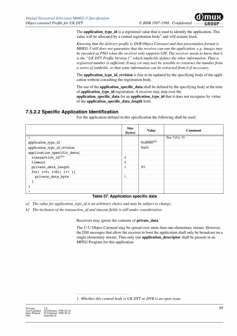
muxGROUP
dDigital Terrestrial Television MHEG-5 SpeciÞcationObject carousel ProÞle for UK DTT © BDB 1997-1998, ConÞdential
The application_type_id is a registered value that is used to identify the application. This value will be allocated by a central registration body1 and will remain Þxed.
Knowing that the delivery proÞle is DVB Object Carousel and that presentation format is MHEG-5 still does not guarantee that the receiver can run the application, e.g. images may be encoded as PNG when the receiver only supports GIF. The receiver needs to know that it is the ÒUK DTT ProÞle Version 1Ó which implicitly deÞnes the other information. Thus a registered number is sufÞcient. It may (or may not) be sensible to construct the number from a series of subÞelds, so that some information can be extracted from it if necessary.
The application_type_id_revision is free to be updated by the specifying body of the appli-cation without consulting the registration body.
The use of the application_speciÞc_data shall be deÞned by the specifying body at the time of application_type_id registration. A receiver may skip over the application_speciÞc_data for an application_type_id that it does not recognise by virtue of the application_speciÞc_data_length Þeld.
1. Whether this central body is UK DTT or DVB is an open issue.
7.5.2.2 SpeciÞc Application IdentiÞcationFor the application deÞned in this speciÞcation the following shall be used:
a] The value for application_type_id is an arbitrary choice and may be subject to change.
b] The inclusion of the transaction_id and timeout Þelds is still under consideration.
Receivers may ignore the contents of private_data.
The U-U Object Carousel may be spread over more than one elementary stream. However, the DSI messages that allow the receiver to boot the application shall only be broadcast on a single elementary stream. Thus only one application_descriptor shall be present in an MPEG Program for this application.
Size (bytes)
Value Comment
: See Table 56
application_type_id 0x8000[a]
application_type_id_revision 0x01application_specific_data{
transaction_id[b] 4timeout 4private_data_length 1 N1for( i=0; i<N1; i++ ){
private_data_byte 1}
}
:
Table 57. Application speciÞc data
Version: 1.0 95Last Updated: 28 February 1998 20:16Date Printed: 28 February 1998 20:21File: ocproÞle.fr

muxGROUP
d Digital Terrestrial Television MHEG-5 SpeciÞcation© BDB 1997-1998, ConÞdential Object carousel ProÞle for UK DTT
7.5.2.3 Other Related PMT Descriptors
7.5.2.4 Example Use of application_descriptorThe following example shows an application where the U-U Object Carousel has been spread over two elementary streams. DSI messages are only broadcast on elementary_stream_1.
Descriptor Comment
carousel_id_descriptor Receivers may ignore this descriptor.
data_broadcast_descriptor Receivers may ignore this descriptor.
data_broadcast_id_descriptor Receivers may ignore this descriptor.
association_tag_descriptorReceivers shall interpret this descriptor as deÞned, except for the selector and private_data Þelds which may be ignored.
deferred_association_tag_descriptor Receivers shall interpret this descriptor as deÞned.
stream_identiÞer_descriptor Receivers shall interpret this descriptor as deÞned.
Table 58. Other PMT descriptors
Size (bytes)
Value
PMT{
< various fields >
first_descriptor_loop{
}
elementary_stream_loop{
elementary_stream_1{
< various fields >
second_descriptor_loop{
application_descriptor(){ See Table 56descriptor_tag 1 0x80descriptor_length 1 0x0Eapplication_type_id 4 0x8000application_type_id_revision 1 0x01application_specific_data_length 1 N3 = 9transaction_id 4 0xFFFFFFFFtimeout 4 0xFFFFFFFFprivate_data_length 1 N1 = 0
}
stream_identifier_descriptor(){ DeÞned by DVBdescriptor_tag 1descriptor_length 1component_tag 1
}
}
}
Table 59. Signalling in the PMT (Sheet 1 of 2)
96 Version: 1.0Last Updated: 28 February 1998 20:16Date Printed: 28 February 1998 20:21
File: ocproÞle.fr

muxGROUP
dDigital Terrestrial Television MHEG-5 SpeciÞcationObject carousel ProÞle for UK DTT © BDB 1997-1998, ConÞdential
elementary_stream_2{
< various fields >
second_descriptor_loop{
stream_identifier_descriptor(){ DeÞned by DVBdescriptor_tag 1descriptor_length 1component_tag 1
}
}
}
}
}
Size (bytes)
Value
Table 59. Signalling in the PMT (Sheet 2 of 2)
Version: 1.0 97Last Updated: 28 February 1998 20:16Date Printed: 28 February 1998 20:21File: ocproÞle.fr

muxGROUP
d Digital Terrestrial Television MHEG-5 SpeciÞcation© BDB 1997-1998, ConÞdential Object carousel ProÞle for UK DTT
7.5.3 Information in the DSI
7.5.3.1 Specifying an Initial ObjectAn initial object, which in this speciÞcation is the Application object to launch, may be explicitly deÞned for reasons of application authoring convenience or to support multiple languages.
It is not mandatory to explicitly specify an initial object. If no initial object is speciÞed then default values will be used. See ÒNo Explicit Initial Object IdentiÞedÓ on page 99.
Explicit initial objects may be speciÞed using an application initial object descriptor in the userInfo Þeld of the ServiceGatewayInfo message (see page 76) as well as in the DSI mes-sage. The initial object value to use (when there is more than one choice) may be determined by the use of ISO language codes.
To specify a default choice or a single, language independent choice the ISO language code ÒundÓ should be used.
No order of preference shall be implied by the order of choices in the loop.
a] The value for application_initial_object_descriptor is an arbitrary choice and may be subject to change.
The initial_object_length shall include a null terminator.
The initial_object Þeld may include a path.
Size (bytes)
Value
application_initial_object_descriptor(){
descriptor_tag 1 0x81[a]
descriptor_length
1 N1
num_initial_objects 1 N2for( j=0; j<N2; j++){
ISO_639_language_code 3initial_object_length 1 N3for( k=0; k<N3; k++){
initial_object_byte 1}
}
}
Table 60. Initial object speciÞcation descriptor
N1 1 4 N3 j( )+j 0=
j N2<
å+=
98 Version: 1.0Last Updated: 28 February 1998 20:16Date Printed: 28 February 1998 20:21
File: ocproÞle.fr
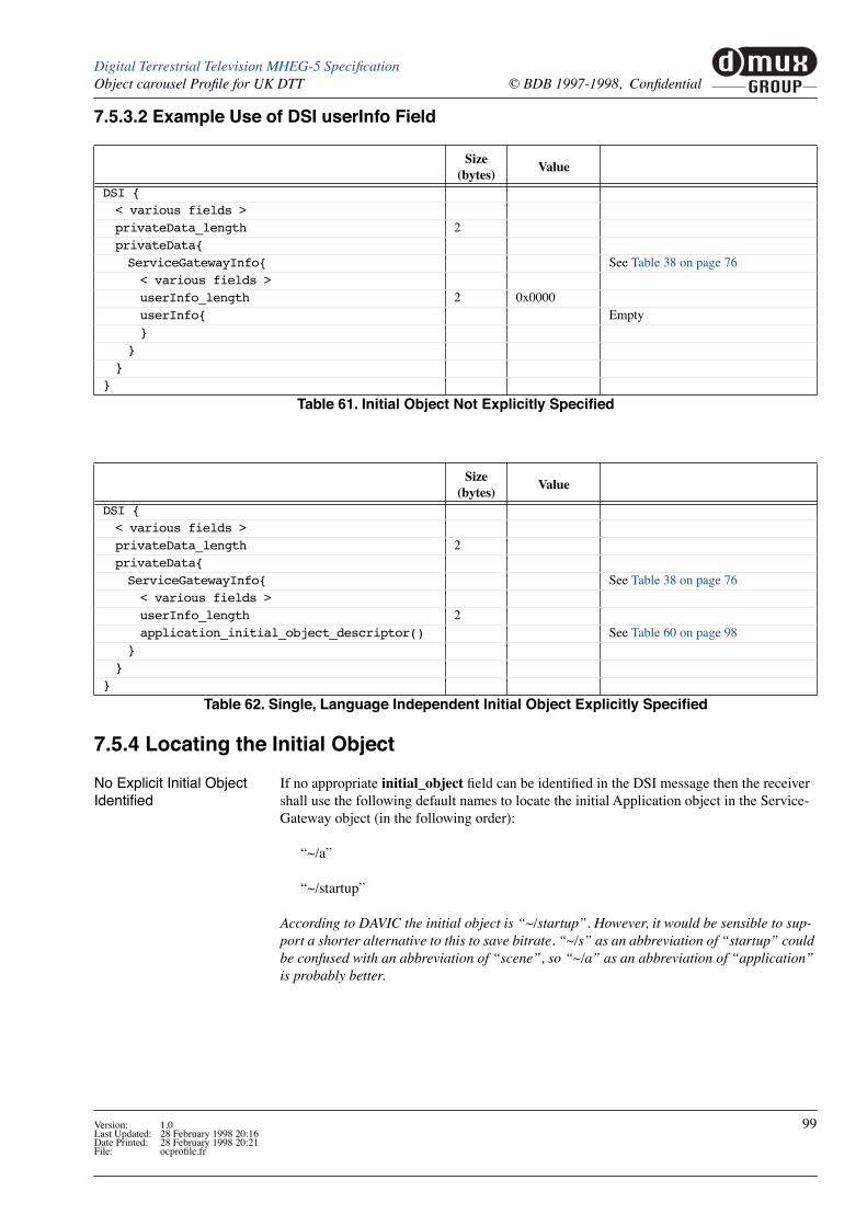
muxGROUP
dDigital Terrestrial Television MHEG-5 SpeciÞcationObject carousel ProÞle for UK DTT © BDB 1997-1998, ConÞdential
7.5.3.2 Example Use of DSI userInfo Field
7.5.4 Locating the Initial Object
No Explicit Initial Object IdentiÞed
If no appropriate initial_object Þeld can be identiÞed in the DSI message then the receiver shall use the following default names to locate the initial Application object in the Service-Gateway object (in the following order):
Ò~/aÓ
Ò~/startupÓ
According to DAVIC the initial object is Ò~/startupÓ. However, it would be sensible to sup-port a shorter alternative to this to save bitrate. Ò~/sÓ as an abbreviation of ÒstartupÓ could be confused with an abbreviation of ÒsceneÓ, so Ò~/aÓ as an abbreviation of ÒapplicationÓ is probably better.
Size (bytes)
Value
DSI {
< various fields >
privateData_length 2privateData{
ServiceGatewayInfo{ See Table 38 on page 76< various fields >
userInfo_length 2 0x0000userInfo{ Empty}
}
}
}
Table 61. Initial Object Not Explicitly SpeciÞed
Size (bytes)
Value
DSI {
< various fields >
privateData_length 2privateData{
ServiceGatewayInfo{ See Table 38 on page 76< various fields >
userInfo_length 2application_initial_object_descriptor() See Table 60 on page 98
}
}
}
Table 62. Single, Language Independent Initial Object Explicitly SpeciÞed
Version: 1.0 99Last Updated: 28 February 1998 20:16Date Printed: 28 February 1998 20:21File: ocproÞle.fr

muxGROUP
d Digital Terrestrial Television MHEG-5 SpeciÞcation© BDB 1997-1998, ConÞdential Object carousel ProÞle for UK DTT
Explicit Initial Object IdentiÞed
If an appropriate initial_object Þeld can be identiÞed from the DSI message then the receiver shall use this to locate the initial Application object.
If the initial_object Þeld identiÞes a File object, this shall be the initial object.
If the initial_object Þeld identiÞes a Directory object, the receiver shall use the default names to locate the initial Application object in this Directory object.
If the initial_object Þeld produces no match in either of the above steps, it shall be dis-carded and the receiver shall use the default names to locate the initial Application object in the ServiceGateway.
So for initial_object:
Òmy_appÓ
The receiver shall work down the following list (in the order shown):
Ò~/my_appÓ
Ò~/my_app/aÓ
Ò~/my_app/startupÓ
Ò~/aÓ
Ò~/startupÓ
7.5.5 Steps Required to Identify and Boot Application1. Tune to the transport stream of the service (MPEG Program).
2. Acquire the PAT.
3. Acquire the PMT of the service using the information in the PAT.
4. Search through the second descriptor loops in the PMT, i.e. the descriptor loop for each elementary stream, for an instance of the application_descriptor containing the appro-priate application_type_id and application_type_id_revision values. This identiÞes the elementary stream on which DSI messages are broadcast.
5. If there is no match, there is no associated application in the service.
6. Acquire the DSI from this elementary stream.
7. Acquire the DII message (DII1) that identiÞes the module (Module1) containing the ServiceGateway object, using information in the DSI message (IOR1).
8. Acquire Module1 using information in DII1.
9. Extract the ServiceGateway object from Module1 using information in IOR1.
10. Get the name of the initial File object (in this case containing an MHEG-5 Application object) using explicit information in the DSI message and/or default values. The location of this File object is relative to the ServiceGateway object.
11. If the name points to subdirectories follow the whole path, Þltering the appropriate Directory objects (essentially repeating steps 6...8 in a more generic fashion as required).
12. Acquire the DII message (DII2) that identiÞes the module (Module2) containing the ini-tial File object, using information in the ServiceGateway object (IOR2).
13. Acquire Module2 using information in DII2.
14. Extract the initial File object from Module2 using information in IOR2.
100 Version: 1.0Last Updated: 28 February 1998 20:16Date Printed: 28 February 1998 20:21
File: ocproÞle.fr

8 Name Mapping
8.1 Names within the receiver
8.2 MHEG-5 Component tagsSee ÒComponent tags for RTGraphicsÓ on page 66.
See ÒTag MappingÓ on page 90.
8.3 DAVIC deÞnitionsThe text here is an extract from DAVIC 1.3 Part 09 [27] provided for information. The formal deÞnition of these resident programs remains the DAVIC document except where noted.
See also:
¥ ÒNon-presented textÓ on page 45
¥ ÒType conversionÓ on page 46
¥ ÒGroupIndentiÞerÓ on page 28
8.3.1 Stream Events and Normal Play Time MappingThe DSM-CC StreamEvent interface provides the possibility to carry private data in the data structure for the event, in the form of the PrivateDataByte Þeld. These bytes shall be mapped one-to-one on the StreamEventTag of the MHEG-5 event StreamEvent.
The MHEG-5 internal attribute CounterPosition of the Stream class shall also be mapped on the value of the DSM-CC Normal Play Time of the corresponding stream. The counter posi-tion shall represent a millisecond precision. Mapping from Normal Play Time to CounterPo-sition shall take place by rounding the value to the nearest millisecond.
8.3.2 Namespace MappingWhen an application starts, it is assumed that a service gateway has been located and attached to, so that there is exactly one name space within which the application objects are located. Within that name space, a service has also been located. That service is a DSM-CC directory; within it, there can be other directories, Þles, and streams.
Furthermore, it is assumed that each object belongs to exactly one application. This assump-tion is necessary to allow for unambiguous object references.
Name Format Use Comment
rec://def_serviceContentReference for a Stream object
This content reference identiÞes the receivers currently selected service. See ÒStream inheritance by applicationsÓ on page 65.
ram://<name>Name space for persistent storage.
See ÒPersistent storageÓ on page 69
Table 63. Names within the receiver
Version: 1.0 101Last Updated: 28 February 1998 20:16Date Printed: 28 February 1998 20:22File: names

muxGROUP
d Digital Terrestrial Television MHEG-5 SpeciÞcation© BDB 1997-1998, ConÞdential Name Mapping
The high-level API differentiates between three types of retrieved data:
¥ objects that comply to the high-level API deÞnition,
¥ the content (such as bitmaps or text) of those objects, and
¥ streams (such as video and audio).
For accessing the various objects of an application on the server side, the DSM-CC Direc-tory, File and Stream objects are used. Note that the server, in this context, does not have to be a physical server, but could be implemented, for example, as a broadcast carousel in a pure-broadcast topology.
Each Þle is either a Scene object, an Application object, or the content data of an Ingredient object. Each Scene object, Application object and content data is stored in a separate Þle.
8.3.3 MHEG-5 Object ReferencesMHEG-5 objects can be exchanged in two ways: either the object is exchanged as a DSM-CC Þle object or within another high-level API object. The former method is used for Appli-cations and Scenes, the latter for all other objects contained in a scene or application object.
MHEG-5 references objects by an ObjectReference, consisting of an optional byte string GroupIdentiÞer, followed by an integer, the ObjectNumber.
For the mapping on DSM-CC, the following additional rules are deÞned:
1. Each Application and Scene object shall have in its GroupIdentiÞer a byte string which maps on the name of the DSM-CC Þle which contains that object. These objects shall have their ObjectNumber set to 0.
2. Each application shall have exactly one Application object. That object shall be con-tained in a DSM-CC File object with the name ÔstartupÕ. Only one Application object shall be contained in each such Þle.
3. Ingredient Objects other than Application and Scene objects may
¥ either leave out the GroupIdentiÞer, in which case it is assumed to be a string which maps on the name of a DSM-CC Þle which contains the object (Application or Scene) of which this object is a part,
¥ or Þll in the GroupIdentiÞer with such a string.
4. Such objects shall have their ObjectNumber set to a value which is unique within that Scene.
5. For the GroupIdentiÞer, the mapping rules deÞned in the following Clause apply.
8.3.3.1 Mapping Rules for GroupIdentiÞerAll GroupIdentiÞers are ASCII strings. They are composed of four components:
Source Path Origin Path Filename
The Source component is optional, and speciÞes the data source to be used to retrieve the data. Each source identiÞcation is terminated with a Ò:Ó. The default source identiÞcation is ÒDSM:Ó (in upper case). DAVIC 1.3 does not specify any further data sources, but the use of other source identiÞcations is permitted.
The Path Origin is either Ô//Õ or Ô/Õ. If the path origin is Ô//Õ then the following path and Þlename are to be interpreted as an absolute path starting from the root of the current service gateway to which the runtime is attached. If the path origin is Ô/Õ then the following path and Þlename is to be interpreted as a relative path, starting from the directory that contains the current Application object.
102 Version: 1.0Last Updated: 28 February 1998 20:16Date Printed: 28 February 1998 20:22
File: names

muxGROUP
dDigital Terrestrial Television MHEG-5 SpeciÞcationName Mapping © BDB 1997-1998, ConÞdential
The Path component is a (possible empty) sequence of directory names, each followed by a Ô/Õ character. Each directory name is to be used to delimit directory references (of the depth type).
The Filename component identiÞes the DSMCC object within the directory that is identiÞed by the preceding Source, Path Origin and Path components.
For instance, if the GroupIdentiÞer is ÔDSM://apps/otherApplÕ, it is mapped on the DSM-CC name ÔotherApplÕ in the directory ÔappsÕ of the service gateway to which the runtime has attached. If the GroupIdentiÞer is ÔDSM:/scenes/mySceneÕ, it is mapped on the DSM-CC name ÔmySceneÕ in the directory ÔscenesÕ of the directory where the Application object was found.
8.3.3.2 Shorthand NotationDAVIC deÞnes shorthand notations for references to objects accessible from the default Data Source. In DAVIC 1.3 the default Data Source is a DSM-CC service gateway. The rationale behind the shorthand notation is compatibility with previous versions of the DAVIC speciÞcation.
There are two abbreviations allowed. The Þrst abbreviation is Ô~/Õ (standard ASCII tilde + slash), which may be used to specify the default Data Source and a relative Path Origin; use in DAVIC 1.3 means ÔDSM:Õ for the Data Source and Ô/Õ for Path Origin. This abbreviation can therefore be used to refer to objects relative to the current application.
The other abbreviation is Ô/Õ (standard ASCII slash), which may be used to specify the default Data Source and an absolute Path Origin; use in DAVIC 1.3 means ÔDSM:Õ for the Source and Ô//Õ for Path Origin. This abbreviation can therefore be used to refer to objects with an absolute path from the root of the current service gateway to which the runtime is attached.
For instance, an object, referred to as ÔDSM:/scenes/mySceneÕ may be referred to as Ô~/scenes/mySceneÕ, while the object referred to as ÔDSM://apps/otherApplÕ may be referred to as Ô/apps/otherApplÕ.
8.3.3.3 Other Service GatewaysIt is possible to refer to objects in another service gateway, as DSMCC objects have built-in indirection to the actual location of the data. An object with the path ÒDSM://Mheg5/Bank-ing/WelcomeÓ can refer to a DSMCC object whose actual data is only accessible from another service gateway. Normal access to such an object will result in a Ôservice transfer exceptionÕ, which will be followed by an attempt to attach to that service gateway.
8.3.4 MHEG-5 Content ReferencesMHEG-5 has a separate way of referencing the actual content of objects belonging to the Ingredient class. This is done by way of a ContentReference. The ContentReference consists of an optional PublicIdentiÞer followed by a SystemIdentiÞer, which is a byte string. The following rule shall apply.
For the SystemIdentiÞer, the exact same mapping shall be used as for the GroupIdentiÞer above. The PublicIdentiÞer shall not be used.
8.3.4.1 DSMCC Stream ObjectsNote that the mapping of ContentReference and GroupIdentiÞer allow references to both DSMCC File and DSMCC Stream objects. Although this is possible, applications shall not refer to DSMCC Stream objects using a GroupIdentiÞer. GroupIdentiÞers are always expected to refer to DSMCC File objects.
ContentReferences of content of MHEG-5 Stream objects may refer to both DSMCC File and DSMCC Stream objects. If such a ContentReference refers to a DSMCC File object, the
Version: 1.0 103Last Updated: 28 February 1998 20:16Date Printed: 28 February 1998 20:22File: names
muxGROUP
d Digital Terrestrial Television MHEG-5 SpeciÞcation© BDB 1997-1998, ConÞdential Name Mapping
MHEG-5 Stream object shall have its Storage attribute set to ÔmemoryÕ. If the ContentRefer-ence refers to a DSMCC Stream object, the MHEG-5 Stream object shall have its Storage attribute set to ÔstreamÕ.
ContentReferences of content of MHEG-5 Ingredients, other than Stream objects must always refer to a DSMCC File object.
8.3.5 URL Format for Access to Broadcast Services
8.3.5.1 IntroductionDAVIC deÞnes a speciÞc Uniform Resource Locator (URL) format to access broadcast serv-ices. This URL format provides a general addressing mechanism intended to access broad-cast services from e.g. JAVA and HTML. Note that URLs are commonly used in JAVA for addressing resources and other objects.
DAVIC broadcast networks carry the Service Information (SI) which contains globally unique parameters for locating the services in the broadcast networks. The URL format deÞned by DAVIC to access such services is based on these parameters as they provide an addressing mechanism in a physical network independent way. The same services may be carried simultaneously in many physical networks, but the parameters in the SI will remain the same and thus they can be used by the clients to locate the services regardless of the actual physical network.
DAVIC deÞned the following general format of the URLs :
<protocol>://<ÒserverÓ>/<dir1>/.../<Þle>
The protocol (scene) part of the URL identiÞes that it is a broadcast service. The ÒserverÓ part of the URL points to the service as the services are the basic element that is carried in the broadcast networks. The rest of the URL speciÞes the individual component inside a service. The format of the last part is dependent on the type of the service (this part is not needed if the URL points to the whole service).
8.3.5.2 Numerical formatThe combination of original_network_id, transport_stream_id and service_id identiÞes a service in a DVB / DAVIC broadcast network globally uniquely. Thus, the Þrst part of the URL in a numerical form can be following:
UK modiÞcation dvb://<original_network_id>.[<transport_stream_id>][.<service_id>[.<component_tag>][;<event_id>]][/<...>]
UK modiÞcation So, URLs specifying a service might be of the form:dvb://abcd.1234.5679
ordvb://abcd..5679
See ETR 211 [8]. Services are unique within the scope of a single original network ID. So, transport stream ID is not required to uniquely specify a service within an original network. The transport stream id (0x1234 in this case) is optional in URLs and can be left empty.
In terrestrial networks the same service may be available to the receiver on more than one transport stream. Where a URL does not deÞne the transport stream ID the receiver is free to choose which transport stream ID it selects when obtaining a service.
The <original_network_id>, <transport_stream_id>, <service_id>, <event_id> and <component_tag> are the values represented as hexadecimal strings without any Ò0xÓ preÞx (for example, Ò4d2eÓ).
104 Version: 1.0Last Updated: 28 February 1998 20:16Date Printed: 28 February 1998 20:22
File: names

muxGROUP
dDigital Terrestrial Television MHEG-5 SpeciÞcationName Mapping © BDB 1997-1998, ConÞdential
Depending on the service the following part of the URL (Ò/<...>Ò) may contain a more detailed speciÞer that identiÞes the desired part of the service. For example, if the service contains a data carousel, the last part of the URL may contain the Þle name.
Version: 1.0 105Last Updated: 28 February 1998 20:16Date Printed: 28 February 1998 20:22File: names

muxGROUP
d Digital Terrestrial Television MHEG-5 SpeciÞcation© BDB 1997-1998, ConÞdential Name Mapping
106 Version: 1.0Last Updated: 28 February 1998 20:16Date Printed: 28 February 1998 20:22
File: names

9 MHEG-5 Authoring Guidelines
9.1 IntroductionThis section describes the measures that should be taken by the broadcaster to ensure good application behaviour.
9.2 Avoiding confusion with navigator functions
9.2.1 Use of user inputs
Requirement The user shall be able to ÒsurfÓ through services with MHEG applications without a change in the user interface behaviour.
Selecting & Entering Two concepts are introduced selecting the MHEG application and entering it.
When the user Þrst navigates to a service that is wholly or partly implemented as an MHEG application it is ÒselectedÓ. If the user interacts with the MHEG aspects of that service they ÒenterÓ it.
Until the user ÒentersÓ the application the channel change facility of the receiver should not be modiÞed by the application.
Limiting Input methods on Þrst selection
Applications should be authored so that none of the user inputs normally associated with changing channel are used by the application until the user has ÒenteredÓ the application.
Doing it The Þrst scene of the application should:
¥ Use an input register that excludes the ÒÒEnteredÓ GroupÓ of keys(i.e. only the ÒÒSelectedÓ GroupÓ)
¥ Require the user to actively select an EntryField, or any other Interactible, before setting its InteractionStatus to True.
These measures mean that when an application is Þrst ÒselectedÓ it makes no use of the ÒÒEnteredÓ GroupÓ of keys. So, these keys retain their usual receiver speciÞc functions (such as Ògo to favourite channelÓ).
An entry Þeld may be included in the Þrst scene (e.g. to allow the user to ÒjumpÓ to a speci-Þed scene). However, it is not initially active, and so wonÕt absorb numeric input. One of the ÒÒSelectedÓ GroupÓ must be used activate the entry Þeld (or to navigate to a scene where the entry Þeld is active). Again this preserves the Ògo to favourite channelÓ function of the ÒÒEnteredÓ GroupÓ of keys.
Within these constraints the author is free to use the ÒÒSelectedÓ GroupÓ of keys to navigate from this Þrst scene.
Starting Applications ÒEnteredÓ
Through use of ÒPersistent storageÓ an application can launch a second application that tran-sitions immediately to an interior ÒenteredÓ scene. This should only be done after the user has ÒenteredÓ the Þrst application.
Version: 1.0 107Last Updated: 28 February 1998 20:16Date Printed: 28 February 1998 20:22File: authoring_requirements.fr

muxGROUP
d Digital Terrestrial Television MHEG-5 SpeciÞcation© BDB 1997-1998, ConÞdential MHEG-5 Authoring Guidelines
9.3 Use of the ÒTextÓ functionThe ÒTextÓ user input event has a speciÞc meaning that should be observed by all applica-tions to avoid confusing the user. It means ÒtoggleÓ the visibility of the MHEG aspect of the service.
9.3.1 The traditional ÒteletextÓ keyIn Figure 22 ÒTextÓ toggles between conventional TV and a full screen MHEG application. This is very similar to the behaviour of todayÕs ÒteletextÓ button.
An available elaboration is that a single ÒteletextÓ service can be shared by a number of TV services.
Entering In this case the Þrst scene of the ÒAuto Start ApplicationÓ associated with the service pro-duces no visible effect. This Þrst ÒinvisibleÓ scene responds to ÒTextÓ either by transitioning to another scene within the same application or by launching a different application.
Leaving If the application is part of the service then the ÒreturnÓ when ÒTextÓ is used a second time can be implemented in various ways:
¥ TransitionTo the Þrst scene
¥ Quitting the application (which will automatically be restarted on the Þrst scene)
¥ Launching the application (which will automatically start on the Þrst scene)
¥ Service change (resident program) to the information application
If the information application is NOT part of the service (i.e. the ÒinvisibleÓ application launched it) then the options are for the visible application to:
¥ Launch the invisible application
¥ Service change (resident program) to the invisible application
If there is a one-to-one relationship between TV service (with invisible ÒspringboardÓ appli-cation) and the information service then the return link can be explicitly coded into the appli-cation.
If more than one ÒTV serviceÓ directs its viewers to a single information service (as might be the case with BBC services funnelling their viewers to a single Ceefax service) then each of the ÒinvisibleÓ applications should store appropriate information in persistent storage to allow returning to the point of origin (See ÒPersistent storageÓ on page 37).
COOK TO ATTEND SADDAM CRISIS MEETINGForeign Secretary Robin Cook is to hold talks with hisUS, Russian and French counterparts over the Iraqcrisis.
The Geneva meeting has been scheduled for theearly hours of tomorrow. The move follows a claim bythe Russian foreign minister that he had hammeredout a possible deal with Iraq in the row over UNweapons inspections.
Meanwhile, President Clinton has ordered B-52bombers and Stealth fighters to beef US forces in theGulf.
Text
Text
Figure 22. ÒTextÓ accesses ÒteletextÓ
Text
Text
108 Version: 1.0Last Updated: 28 February 1998 20:16Date Printed: 28 February 1998 20:22
File: authoring_requirements.fr
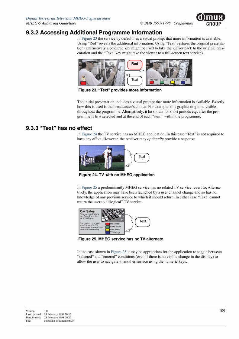
muxGROUP
dDigital Terrestrial Television MHEG-5 SpeciÞcationMHEG-5 Authoring Guidelines © BDB 1997-1998, ConÞdential
9.3.2 Accessing Additional Programme InformationIn Figure 23 the service by default has a visual prompt that more information is available. Using ÒRedÓ reveals the additional information. Using ÒTextÓ restores the original presenta-tion (alternatively a coloured key might be used to take the viewer back to the original pres-entation and the ÒTextÓ key might take the viewer to a full-screen text service).
The initial presentation includes a visual prompt that more information is available. Exactly how this is used is the broadcasterÕs choice. For example, this graphic might be visible throughout the programme. Alternatively, it be shown for short periods e.g. after the pro-gramme is Þrst selected and at the end of each ÒitemÓ within the programme.
9.3.3 ÒTextÓ has no effectIn Figure 24 the TV service has no MHEG application. In this case ÒTextÓ is not required to have any effect. However, the receiver may optionally provide a response.
In Figure 25 a predominantly MHEG service has no related TV service revert to. Alterna-tively, the application may have been launched by a user channel change and so has no knowledge of any previous service to which it should return. In either case ÒTextÓ cannot return the user to a ÒlogicalÓ TV service.
In the case shown in Figure 25 it may be appropriate for the application to toggle between ÒselectedÓ and ÒenteredÓ conditions (even if there is no visible change in the display) to allow the user to navigate to another service using the numeric keys.
Info Pack Courses Next Week Reveal
Figure 23. ÒTextÓ provides more information
Red
Text
Text
Figure 24. TV with no MHEG application
Car SalesNew car registrationsthis August were 3%up on last year.
Car production in 1997was 5% up. 150,000unsold cars are now storedin around the country
Main IndexNews IndexNext NewsTV Listings
Text
Figure 25. MHEG service has no TV alternate
Version: 1.0 109Last Updated: 28 February 1998 20:16Date Printed: 28 February 1998 20:22File: authoring_requirements.fr

muxGROUP
d Digital Terrestrial Television MHEG-5 SpeciÞcation© BDB 1997-1998, ConÞdential MHEG-5 Authoring Guidelines
9.4 Changing Applications at Programme (Event) boundariesIn some cases MHEG applications will be associated with a particular TV programme. So, as the schedule progresses applications must die and new ones replace them.
Various strategies are available to create the effect seen in Figure 26. In Figure 27 the receiverÕs auto start behaviour is used to start an appropriate application at the start of each programme.
In Figure 28 the MHEG application carousel operates continuously periodically being updated with new applications. Applications explicitly launch their successor.
The receiverÕs auto start behaviour is still required to start the Þrst application of the day and to start applications when viewers join the service.
Walking holidays in the jungles of Sarawakstart from £599 for 7 night fromFarm Road Holidays TEXT
Tim
e 1) Programme with no application
2) Programme with Þrst application
3) Programme with second application
Figure 26. A progression of applications through the schedule
Figure 27. Dead manÕs shoes method
Programme (1) Programme (2) Programme (3)
MHEG stream
MPEG AV stream
Receiver Auto Starts application
Application kills itself
Receiver Auto Starts next application
Figure 28. Baton passing method
Programme (1) Programme (2) Programme (3)
MHEG stream
MPEG AV stream
Invisible application Application launches its successor
Application launches its successor
110 Version: 1.0Last Updated: 28 February 1998 20:16Date Printed: 28 February 1998 20:22
File: authoring_requirements.fr

muxGROUP
dDigital Terrestrial Television MHEG-5 SpeciÞcationMHEG-5 Authoring Guidelines © BDB 1997-1998, ConÞdential
9.5 MHEG streamsEach program (service) may contain at most one MHEG application designated as an autostart application.
There may be a number of other non-autostart applications. These are always Launched by other applications.
A TS may contain any number of MHEG services.
9.6 Use of the display
9.6.1 Visible AreaTypically a 5% border region is lost due to monitor overscan. This leaves a central 648x518 area of the graphics plane which will normally be visible provided that the user does not conÞgure their equipment in an unusual way. For example, additional area may be lost if a 4/3 service is ÒzoomedÓ to Þle a 16/9 display.
9.6.2 Scene Aspect RatioWhere an MHEG application is associated with one or more video streams, the scene Aspec-tRatio shall be equivalent to the aspect ratio of the video.
9.7 Use of stream decodersReceivers conforming to UKEngineProÞle1 are modelled as providing just one of each of the following decoders:
¥ MPEG video or still picture
¥ MPEG audio
¥ DVB Subtitle
To obtain deterministic behaviour authorÕs should not build applications that attempt to acti-vate more than one of each type of decoder. E.g. applications should Stop a running Stream object using MPEG video before Running a Bitmap object with MPEG I-frame content.
See ÒNumbers of ObjectsÓ on page 43.
9.8 Missed eventsApplications are not guaranteed to receive all events. For example, stream events and timer events may be missed while an application is paused as a consequence of losing priority access to the display. See ÒGraphics priorityÓ on page 44.
9.9 File naming
Name length The length of Þle references is limited. See ÒGroupIndentiÞerÓ on page 28.
Name character coding The character set for Þle references is limited. See ÒNon-presented textÓ on page 45.
File names in persistent storage
The <name> part of the Þle name Òram://<name>Ó used to access Þles in persistent storage (See ÒPersistent storageÓ on page 69) shall be managed to avoid accidental Þle name colli-sion between the applications of different service providers.
The length of <name> is deÞned in ÒStorage of Þle namesÓ on page 70. The Þrst characters of these names are allocated to multiplex operators as shown in Table 64 where ÔxxxxxÕ
Version: 1.0 111Last Updated: 28 February 1998 20:16Date Printed: 28 February 1998 20:22File: authoring_requirements.fr

muxGROUP
d Digital Terrestrial Television MHEG-5 SpeciÞcation© BDB 1997-1998, ConÞdential MHEG-5 Authoring Guidelines
indicates characters that may be allocated by the multiplex operator to services and applica-tions as they choose.
Where an application (or co-operating applications) is (are) delivered by more than one mul-tiplex operator the application author shall be responsible for liaising with the multiplex operators to obtain a <name> allocated within the space of one operator.
Further names ÒrootsÓ may be allocated following mutual agreement between all the multi-plex operators.
9.10 Text and HyperText encodingMark-up coding for Text and HyperText objects is described in ÒText ObjectsÓ on page 54 and ÒHyperText ObjectsÓ on page 55 is functionally equivalent to a small subset of HTML re-coded to improve transmission efÞciency. A simple translation process between the two formats is possible.
a] Tab characters have meaning See ÒTabulationÓ on page 52.
b] All space characters are signiÞcant.
c] And so on. I.e. the HTML Ònamed character entitiesÓ can be directly represented with a simple character code where they exist in the ÒCharacter repertoireÓ on page 58.
<name> format multiplex operator
BBCxxxxx BBC
D34xxxxx Digital 3/4
SDNxxxxx SDN
BDBxxxxx BDB
Table 64. Format of Þle names for persistent storage
HTML mark-up broadcast mark-up codes
0x09[a]
0x20[b]
0xC2 0xA0
<BR> 0x0D
<P>
</P> 0x0D 0x0D
<B> [text in bold] </B> 0x1B 0x42 0x00 [text in bold] 0x1B 0x42
<FONT COLOR="#rrggbbtt"> [coloured text] </FONT> 0x1B 0x43 0x04 0xrr 0xgg 0xbb 0xtt [coloured text] 0x1B 0x43
<A HREF="tag bytes"> [anchor text] </A> 0x1B 0x41 0xnn tag_bytes [anchor text] 0x1B 0x41
< 0x3C
> 0x3E
&[c] 0x26
Table 65. Text object mark-up codes
112 Version: 1.0Last Updated: 28 February 1998 20:16Date Printed: 28 February 1998 20:22
File: authoring_requirements.fr

10 References
10.1 ETSI
10.2 CENELEC
[1] ETS 300 468 Digital broadcasting systems for television, sound and data services; SpeciÞcation for Service Information (SI) in Digital Video Broadcasting (DVB) systems.
[2] ETS 300 743 Digital broadcasting systems for television, sound and data services; Subtitling sys-tems.
[3] prETS 300801 Digital Video Broadcasting (DVB); DVB interaction channel through the Public Switched Telecommunications System (PSTN) / Integrated Services Digital Network (ISDN).
[4] prETS 300802 Digital Video Broadcasting (DVB); Network Independent Protocols for DVB Inter-active Services.
[5] Draft EN 301 192 Digital Video Broadcasting (DVB); DVB speciÞcation for data broadcasting
[6] ETR 154 Digital broadcasting systems for television; Implementation Guidelines for the use of MPEG-2 Systems, Video and Audio in Satellite and Cable Broadcasting Applica-tions.
[7] ETR 162 Digital broadcasting systems for television, sound and data services; Allocation of Service Information (SI) codes for Digital Video Broadcasting (DVB) systems.
[8] ETR 211 Digital broadcasting systems for television, sound and data services; Guidelines on the implementation and usage Service Information (SI). August 1997 Second Edi-tion.
[9] prEN 50201 Interfaces for DVB-IRDs
[10] prEN 50221 Common Interface SpeciÞcation for Conditional Access and other Digital Video Broadcasting Decoder Applications
113 Version: 1.0Last Updated: 28 February 1998 20:16Date Printed: 28 February 1998 20:22
File: rfrncs.frm
10.3 ISO/IEC
10.4 DVB
10.5 ITU
[11] ISO/IEC 11172-2 MPEG 1 video
[12] ISO/IEC 11172-3 MPEG 1 audio
[13] ISO/IEC 13522-5 MHEG-5
Information technology - Coding of multimedia and hypermedia information: Sup-port for Base-Level Interactive Applications.
[14] ISO/IEC 13818-1 Information technology - Generic coding of moving pictures and associated audio information: Systems. ISO/IEC 13818-1:1996(E)
[15] ISO/IEC 13818-2 Information technology - Generic coding of moving pictures and associated audio information: Video.
[16] ISO/IEC 13818-3 Information technology - Generic coding of moving pictures and associated audio information: Audio.
[17] ISO/IEC 13818-6 Information technology - Generic coding of moving pictures and associated audio information: Extensions for Digital Storage Media Command and Control.
[18] ISO 10646-1 Information Technology - Universal Multiple-Octet Coded Character Set (UCS) - Part 1: Architecture and Basic Multilingual Plane.
Also see ÒThe Unicode Standard, Version 2.0Ó, The Unicode Consortium published by Addison-Wesley. ISBN 0-201-48345-9.
[19] DVB A008 DVB Commercial requirements for asymmetric interactive services supporting broadcast to the home with narrow band return channels.
[20] DVB V2 SI 244 DVB Data Broadcasting Services - Commercial Requirements.
[21] SI-DAT 382 Rev. 4 Implementation Guidelines for Databroadcasting
[22] ITU-T X.680 INFORMATION TECHNOLOGY Ð ABSTRACT SYNTAX NOTATION ONE (ASN.1): SPECIFICATION OF BASIC NOTATION
Also published as ISO/IEC International Standard 8824-1.
ASN.1
[23] ITU-T X.690 INFORMATION TECHNOLOGY Ð ASN.1 ENCODING RULES: SPECIFICA-TION OF BASIC ENCODING RULES (BER), CANONICAL ENCODING RULES (CER) AND DISTINGUISHED ENCODING RULES (DER)
Also published as ISO/IEC International Standard 8825-1.
DER
Version: 1.0 114Last Updated: 28 February 1998 20:16Date Printed: 28 February 1998 20:22File: rfrncs.frm

muxGROUP
dDigital Terrestrial Television MHEG-5 SpeciÞcationReferences © BDB 1997-1998, ConÞdential
10.6 Apple Corporation Inc.
10.7 W3C
10.8 DAVIC
[24] AIFF-C AIFF-C Audio Interchange File Format, version C, allowing for Compression.
[25] HTML 3.2 HyperText Mark-up Language reference speciÞcation, by Dave Raggett, 14-Jan-1997
available at http://www.w3.org/TR/REC-html32.html
[26] PNG Portable Network Graphics SpeciÞcation, Version 1.0, 01-October-1996
available at http://www.w3.org/TR/REC-png.html
[27] DAVIC 1.3 Part 09 DAVIC 1.3 SpeciÞcation Part 09, Information Representation, Revision 6.1
[28] DAVIC 14B94R10 DAVIC 1.4 Baseline document 94, Revision 1.0, ÒMHEG-5 Resident Programs to access SI.Ó
Version: 1.0 115Last Updated: 28 February 1998 20:16Date Printed: 28 February 1998 20:22File: rfrncs.frm

muxGROUP
d Digital Terrestrial Television MHEG-5 SpeciÞcation© BDB 1997-1998, ConÞdential References
116 Version: 1.0Last Updated: 28 February 1998 20:16Date Printed: 28 February 1998 20:22
File: rfrncs.frm