digital technique of fault study of power system · pdf filedigital technique of fault study...
TRANSCRIPT
International Research Journal of Engineering and Technology (IRJET) e-ISSN: 2395 -0056
Volume: 03 Issue: 07 | July -2016 www.irjet.net p-ISSN: 2395-0072
© 2016, IRJET | Impact Factor value: 4.45 | ISO 9001:2008 Certified Journal | Page 162
Digital Technique of fault study of power system
Pralay Roy1, Shubham kumar Gupta2
1Assistant professor, Dept. of Electrical Engineering, Siliguri Institute of Technology, sukna, Darjeeling 2Third year student, Dept. of Electrical Engineering, Siliguri Institute of Technology, sukna, Darjeeling
------------------------------------------------------------------***------------------------------------------------------------
Abstract -In huge complex power system networks, faults are inevitable. It’s very important to analyze the fault level for avoiding the severe consequences and proving the conditions thus quality power supply need not to face any kind of discontinuity. The objective of this paper is to study the common fault types which are balanced and unbalanced fault of transmission line in power system using a systematic procedure of digital techniques and to perform the analysis and obtain the result from simulation on that type of fault using MATLAB. Key Words:Power system fault analysis, Asymmetrical fault, Symmetrical components, MATLAB, Z-parameters.
1.INTRODUCTION Power system works in normal balanced condition but whenever some fault arises it becomes unbalanced. Any unexpected disturbance in the normal working condition is termed as fault. Fault may arise due to various factors such as Lightening stroke, high wind which leads to falling of trees on line, wind and ice loading resulting in failure of insulators. Fault can be symmetrical or unsymmetrical, when the fault occurs at all the three phases at a time, it is said to be symmetrical fault and where one or more phases may be involved is unsymmetrical fault. Though the symmetric fault is rare, but this type of faults shows most severe effects to our power systems. Unsymmetrical fault can be treated as a regular problem of the power system and has to be analyzed more preciously thus the system can remain in its stable condition and can lead its operation without breaking continuity. The point at which the fault occurs behaves as sink point and the voltage at that point tends to become zero. Thus all the points have potential higher than faulty point starts to send current to these faulty point and thus the fault level rises to very higher magnitude than normal operating level. Therefore, it is important to determine the values of system voltage and current during fault conditions so that the protective devices may be set to detect the fault and isolate the faulty portion of the system.
1.1 Faults in Three phase system 1. Symmetrical three-phase fault
2. Single line-to-ground fault
3. Line-to-line fault
4. Double line-to-ground fault
Symmetrical fault is defined as the simultaneous short circuit across all the three phases. It is most infrequent fault but the most severe type of fault encountered. Symmetrical fault is the rarest one and calculation of fault level is much simpler, but in case of unsymmetrical symmetry faulted power system does not have three phase symmetry, so it cannot be solved by per phase analysis. To find fault current and voltage, it is first transformed into their symmetrical component, use of which help to reduce the complexity of transmission line and components are by large and symmetrical, although the fault may be unsymmetrical .This can be done by replacing three phase fault current by the sum of three phases zero sequence sources, a three phase positive sequence source, a three phase negative sequence.
1.2 BUS IMPEDENCE CALCULATION
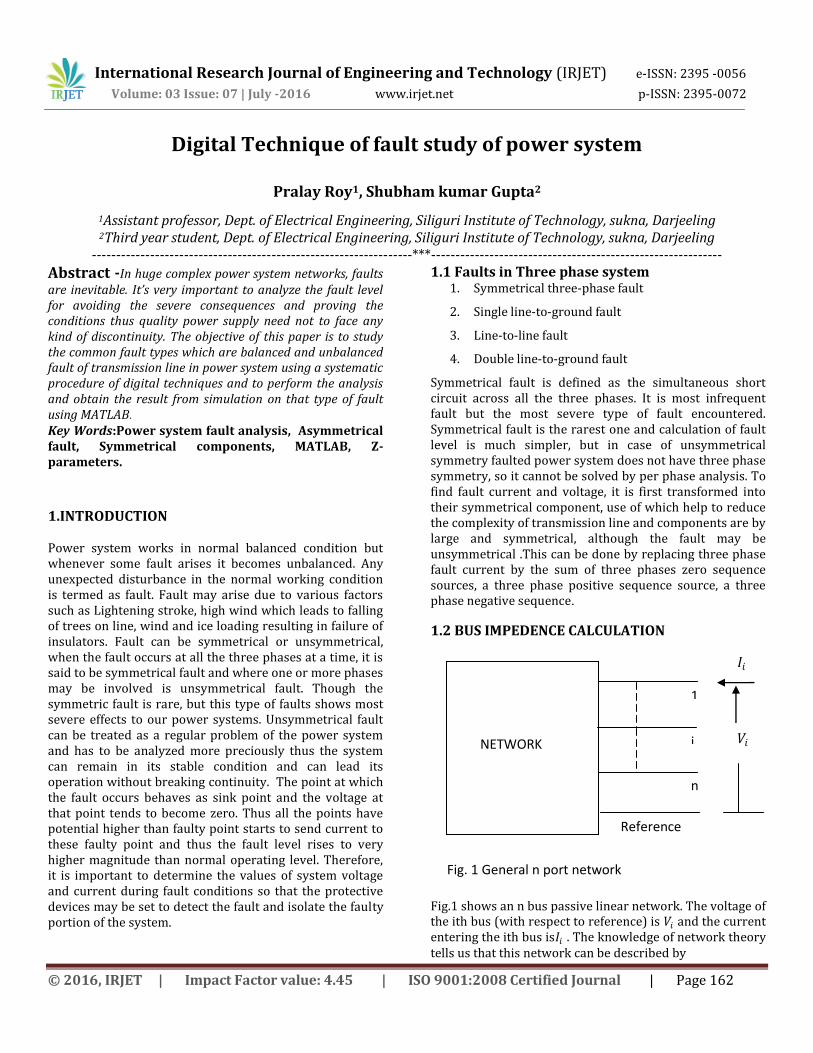
Fig.1 shows an n bus passive linear network. The voltage of the ith bus (with respect to reference) is 𝑉𝑖 and the current entering the ith bus is𝐼𝑖 . The knowledge of network theory tells us that this network can be described by
Reference
1
i
n
NETWORK
𝐼𝑖
𝑉𝑖
Fig. 1 General n port network

International Research Journal of Engineering and Technology (IRJET) e-ISSN: 2395 -0056
Volume: 03 Issue: 07 | July -2016 www.irjet.net p-ISSN: 2395-0072
© 2016, IRJET | Impact Factor value: 4.45 | ISO 9001:2008 Certified Journal | Page 163
𝑉𝑏𝑢𝑠 𝑛×1 = 𝑍𝑏𝑢𝑠 𝑛×𝑛 𝐼𝑏𝑢𝑠 𝑛×1
Where 𝑉𝑏𝑢𝑠 is the bus voltage matrix,𝐼𝑏𝑢𝑠 is the bus current matrix and 𝑍𝑏𝑢𝑠 is the bus impedance matrix. The general entry 𝑍𝑖𝑘 of 𝑍𝑏𝑢𝑠 can be obtained
𝑍𝑖𝑘 = 𝑉𝑖
𝐼𝑘
𝐼1=𝐼2 .......=𝐼𝑛=0
𝐼𝑘 ≠ 0
When an existing𝑍𝑏𝑢𝑠 is added with new element having self-impedance 𝑍𝑠 , a new bus may be created or a new bus may not be created. This leads to the addition of 𝑍𝑠 in the following ways:
1. Injection of𝑍𝑠 from a new bus to reference. 2. Injection of𝑍𝑠 from a new bus to old bus. 3. Injection of𝑍𝑠 from an old bus to reference 4. Injection of𝑍𝑠 between two old buses.
TYPE 1 MODIFICATION Fig. 2 shows a branch 𝑍𝑠 connected between reference bus and a new bus q. For this new branch we can write
𝑉𝑞 = 𝑧𝑠𝐼𝑞
Or 𝑍𝑏𝑢𝑠 𝑛𝑒𝑤 =
S
bus
Z
oldZ
0...0
0
:
0
TYPE 2 MODIFICTION
𝑉𝑞 = 𝑧𝑠𝐼𝑞 + 𝑉𝑘
= 𝑍𝑘1𝐼1 + 𝑍𝑘2𝐼2 + ......... + 𝑍𝑘𝑘 𝐼𝑘 + ........ + 𝑍𝑘𝑛 𝐼𝑛 + (𝑍𝑘𝑘 +𝑧𝑠)𝐼𝑞
The equation for 𝑉1can be written by considering that new current at kth bus is𝐼𝑘 + 𝐼𝑞 .
𝑉1= 𝑍11𝐼1 + 𝑍12𝐼2 + ......... + 𝑍1𝑘𝐼𝑘 + ........ + 𝑍1𝑛𝐼𝑛 +𝑍1𝑘𝐼𝑞
The equations for 𝑉2, 𝑉3 …… . 𝑉𝑛 also get modified in a similar manner and is given by
Reference Fig. 2 Type 1 modification
Network
𝑍𝑠 𝑉𝑞
𝐼𝑞 q
1
n
1
n
Network
q
𝐼𝑞
𝐼𝑘 + 𝐼𝑞 k
𝐼𝑘
𝑍𝑠
Fig. 3 Type 2 modification Reference

International Research Journal of Engineering and Technology (IRJET) e-ISSN: 2395 -0056
Volume: 03 Issue: 07 | July -2016 www.irjet.net p-ISSN: 2395-0072
© 2016, IRJET | Impact Factor value: 4.45 | ISO 9001:2008 Certified Journal | Page 164
TYPE 3 MODIFICATION The new set of the equation is
𝑜𝑟 𝑍𝑏𝑢𝑠 𝑛𝑒𝑤 = 𝑍𝑏𝑢𝑠 𝑜𝑙𝑑 - 1
𝑍𝑘𝑘 +𝑧𝑠
𝑍1𝑘
𝑍2𝑘:
𝑍𝑛𝑘
𝑍𝑘1 𝑍𝑘2 … . 𝑍𝑘𝑛
TYPE 4 MODIFICATION
𝑉𝐾 = 𝑍𝑠+𝑉𝑖
Or =𝑧𝑠𝐼𝑞+𝑍𝑖1𝐼1 + 𝑍𝑖2𝐼2+.......+𝑍𝑖𝑖(𝐼𝑖 + 𝐼𝑞 ) + 𝑍𝑖𝑗 𝐼𝑗 +𝑍𝑖𝑘 (𝐼𝑘 −
𝐼𝑞 )+.........
Rearranging
0 = (𝑍𝑖1 − 𝑍𝑘1)𝐼1 + ... + (𝑍𝑖𝑖 − 𝑍𝑘𝑖 )𝐼𝑖 + (𝑍𝑖𝑗 − 𝑍𝑘𝑗 )𝐼𝑗 +
(𝑍𝑖𝑘 − 𝑍𝑘𝑘 )𝐼𝑘 +....+(𝑧𝑠 + 𝑍𝑖𝑖 − 𝑍𝑖𝑘 − 𝑍𝑘𝑖 + 𝑍𝑘𝑘 )
Equations 𝑉1, 𝑉2, 𝑉3 ………𝑉𝑛 can be written in the
following form:
Or 𝑍𝑏𝑢𝑠 𝑛𝑒𝑤 = 𝑍𝑏𝑢𝑠 𝑜𝑙𝑑 -
1
𝑍𝑠+𝑍𝑖𝑖+𝑍𝑘𝑘 −2𝑍𝑖𝑘
𝑍1𝑖 − 𝑍1𝑘
𝑍2𝑖 − 𝑍2𝑘::
𝑍𝑛𝑖 − 𝑍𝑛𝑘
(𝑍𝑖1 − 𝑍𝑘1) …… (𝑍𝑖𝑛 − 𝑍𝑘𝑛 )
1.3 SEQUENCE MATRICES The sequence impedance matrices required for the short
circuit studies are:
𝑍0−𝑏𝑢𝑠 = zero sequence bus impedance matrix (n×
𝑛),generally entry 𝑍𝑖𝑘0
𝑍1−𝑏𝑢𝑠 = positive sequence bus impedance matrix
(n× 𝑛),generally entry 𝑍𝑖𝑘1
𝑍2−𝑏𝑢𝑠 = negative sequence bus impedance matrix
(n× 𝑛),generally entry 𝑍𝑖𝑘2
The equations relating the sequence quantities are:
𝑉0−𝑏𝑢𝑠 = - 𝑍0−𝑏𝑢𝑠 𝐼0−𝑏𝑢𝑠
𝑉1−𝑏𝑢𝑠 = 𝐸𝑏𝑢𝑠 - 𝑍1−𝑏𝑢𝑠 𝐼1−𝑏𝑢𝑠
Network
Reference
𝑍𝑠 𝐼𝑞
1
n
k
Fig. 4 Type 3 modification
n
Network
𝑍𝑠
i k
Reference Fig. 5 Type 4 modification
1
𝐼𝑖
𝐼𝑘

International Research Journal of Engineering and Technology (IRJET) e-ISSN: 2395 -0056
Volume: 03 Issue: 07 | July -2016 www.irjet.net p-ISSN: 2395-0072
© 2016, IRJET | Impact Factor value: 4.45 | ISO 9001:2008 Certified Journal | Page 165
𝑉2−𝑏𝑢𝑠 = - 𝑍2−𝑏𝑢𝑠 𝐼2−𝑏𝑢𝑠
The prefault currents are neglected, vector E contains 1∠0
in all entries. The currents are all zero till the network is
terminated externally . At a time only one bus( i.e. faulted
bus k ) is terminated. Thus, only 𝐼𝑘0 , 𝐼𝑘1 , 𝐼𝑘2 have non-zero
entry
1.4 SHORT CIRCUIT STUDIES
Symmetrical fault :-For a symmetrical fault the negative sequence and zero sequence are absent, i.e.,𝑉0−𝑏𝑢𝑠 ,𝑉2−𝑏𝑢𝑠 ,𝐼0−𝑏𝑢𝑠 and 𝐼2−𝑏𝑢𝑠 are zero.
𝑉𝑘1=E-(𝑍𝑘11𝐼11 + 𝑍𝑘21𝐼21 + ⋯+ 𝑍𝑘𝑘1𝐼𝑘1 + ⋯ +𝑍𝑘𝑛1𝐼𝑛1) (1)
But all the currents except the current at the faulted bus, i.e., 𝐼𝑘1are zero. Therefore,
𝑉𝑘1 = E-𝑍𝑘𝑘1𝐼𝑘1 (2)
If 𝑍𝑓 is the fault impedance
𝑉𝑘1 =𝐼𝑘1𝑍𝑓 (3)
From (2 and 3)
𝐼𝑘1 = 𝐸
𝑍𝑘𝑘 1+𝑍𝑓 (4)
The voltage at ith bus is
𝑉𝑖1 = E − Zik 1𝐼𝑘1 = E (1- Zik 1
𝑍𝑘𝑘 1+𝑍𝑓) (5)
For i = 1, 2 ......... n
Single Line to Ground Fault
Fig. 7: - Single Line-to-ground fault.
Assuming that fault current 𝐼𝑓 occurred on the phase with
fault impedance 𝑍𝑓 . The boundary conditions are:
n
General zero
sequence
network
modified for
fault analysis
1
k
Reference
𝐼0𝑘
𝑉0𝑘
Fig. 6(a) system zero
sequence network
𝐼1𝑘
General positive
sequence network
modified for fault
analysis
N
Reference
1
n
k
𝑉1𝑘
Fig. 6(b) system positive
sequence network
General negative
sequence
network
modified for
fault analysis
1
k
n
Reference
𝐼2𝑘
𝑉2𝑘
Fig. 6(c) system negative
sequence network

International Research Journal of Engineering and Technology (IRJET) e-ISSN: 2395 -0056
Volume: 03 Issue: 07 | July -2016 www.irjet.net p-ISSN: 2395-0072
© 2016, IRJET | Impact Factor value: 4.45 | ISO 9001:2008 Certified Journal | Page 166
𝑉𝑎𝑔 = 𝑍𝑓𝐼𝑎
𝐼𝑏 = 0, 𝐼𝐶 = 0
The symmetrical component of current are, with𝐼𝑏=𝐼𝐶=0 :
𝐼𝑎0
𝐼𝑎1
𝐼𝑎2
= 1
3 1 1 11 𝑎 𝑎2
1 𝑎2 𝑎
𝐼𝑎 = 𝐼𝑓00
𝐼𝑎0=𝐼𝑎1
=𝐼𝑎2=𝐼𝑓
3
𝐼𝑓 = 𝐼𝑎 = 𝐼𝑎0+𝐼𝑎1
+𝐼𝑎2=
3𝑉𝑓
𝑍0+ 𝑍1+𝑍2+3𝑍𝑓
Where, 𝑍0, 𝑍1 , 𝑍2 is a zero, positive, negative sequence impedance.
Using Z-parameters analysis (Digital approach)
We know that
𝑰𝒊𝟎 = 𝑰𝒊𝟏 = 𝑰𝒊𝟐 = 𝟎 For i = 1, 2 ...... n (6a)
i≠ K (6b)
And 𝐼𝑘0 = 𝐼𝑘1 = 𝐼𝑘2
𝑉𝑘0 + 𝑉𝑘1 + 𝑉𝑘2 = 3𝑍𝑓𝐼𝑘1 (7)
Also 𝑉𝑘0 = -𝑍𝑘𝑘0𝐼𝑘0
𝑉𝑘1 = E-𝑍𝑘𝑘1𝐼𝑘1 (8)
𝑉𝑘2= -𝑍𝑘𝑘2𝐼𝑘2
Combining equation (6, 7 and 8)
𝐼𝑘1 = 𝐸
𝑍𝑘𝑘 0+𝑍𝑘𝑘 1 +𝑍𝑘𝑘 2+3𝑍𝑓 (9)
The sequence components of bus voltages at ith bus (i = 1, 2, 3 ..... n) are
𝑉𝑖0= -𝑍𝑖𝑘0𝐼𝑘0 =−𝑍𝑖𝑘0𝐼𝑘1 (10a)
=−𝑍𝑖𝑘0𝐸
𝑍𝑘𝑘 0+𝑍𝑘𝑘 1 +𝑍𝑘𝑘 2+3𝑍𝑓 (10b)
𝑉𝑖1 = E-𝑍𝑖𝑘1𝐼𝑘1 (11a)
= E [1-𝑍𝑖𝑘1
𝑍𝑘𝑘 0+𝑍𝑘𝑘 1 +𝑍𝑘𝑘 2+3𝑍𝑓 ] (11b)
= E [𝑍𝑘𝑘 0+𝑍𝑘𝑘 1 +𝑍𝑘𝑘 2+3𝑍𝑓−𝑍𝑖𝑘1
𝑍𝑘𝑘 0+𝑍𝑘𝑘 1 +𝑍𝑘𝑘 2+3𝑍𝑓 ] (11c)
𝑉𝑖2= -𝑍𝑖𝑘2𝐼𝑘2= -𝑍𝑖𝑘2𝐼𝑘1 (12a)
=−𝑍𝑖𝑘2𝐸
𝑍𝑘𝑘 0+𝑍𝑘𝑘 1 +𝑍𝑘𝑘 2+3𝑍𝑓 (12b)
Line to Line Fault
Fig.8: Line-to-Line fault
Line-to-Line fault takes place on phase b and c. The boundary conditions are:
𝐼𝑎 = 0
𝐼𝑏+ 𝐼𝐶 = 0
𝑉𝑏= 𝑉𝑐
The symmetrical component of current are:
𝐼𝑎0
𝐼𝑎1
𝐼𝑎2
= 1
3 1 1 11 𝑎 𝑎2
1 𝑎2 𝑎
0 𝐼𝑏−𝐼𝑏
𝐼𝑎0
𝐼𝑎1
𝐼𝑎2
=
01
3(𝑎 − 𝑎2)𝐼𝑏
−1
3(𝑎 − 𝑎2)𝐼𝑏
Therefore, 𝐼𝑎1= - 𝐼𝑎2
Also 𝑉𝑎1 = 𝑉𝑎2
Or 𝐼𝑎1=
𝑉𝑓
𝑍1+𝑍2
Where, 𝑍1 , 𝑍2 is positive, negative sequence impedances.
Using Z-parameters analysis (Digital approach)
For a line to line fault
𝑉0−𝑏𝑢𝑠 = 𝐼0−𝑏𝑢𝑠 = 0 (13)

International Research Journal of Engineering and Technology (IRJET) e-ISSN: 2395 -0056
Volume: 03 Issue: 07 | July -2016 www.irjet.net p-ISSN: 2395-0072
© 2016, IRJET | Impact Factor value: 4.45 | ISO 9001:2008 Certified Journal | Page 167
(6a and 8) are still valid
𝑉𝑘1 = 𝑉𝑘2+ 𝐼𝑘1𝑍𝑓 (14)
Substituting the values for 𝑉𝑘1 and 𝑉𝑘2from (7) into (13)
E − 𝑍𝑘𝑘1𝐼𝑘1 = -𝑍𝑘𝑘2𝐼𝑘2+ 𝐼𝑘1𝑍𝑓 (15)
We know that for a line to line fault 𝐼𝑘2 = -𝐼𝑘1 . Making this substitution in (14)
E − 𝑍𝑘𝑘1𝐼𝑘1 = 𝑍𝑘𝑘2𝐼𝑘1 + 𝐼𝑘1𝑍𝑓
Or 𝐼𝑘1 = 𝐸
𝑍𝑘𝑘 1+𝑍𝑘𝑘 2+𝑍𝑓 (16)
The positive and negative sequence voltages at ith bus (i = 1, 2 ...... n) are
𝑉𝑖1 = E-𝑍𝑖𝑘1𝐼𝑘1 (17a)
= E-𝑍𝑖𝑘1𝐸
𝑍𝑘𝑘 1+𝑍𝑘𝑘 2+𝑍𝑓 (17b)
= E[𝑍𝑘𝑘 1+𝑍𝑘𝑘 2+𝑍𝑓−𝑍𝑖𝑘1
𝑍𝑘𝑘 1+𝑍𝑘𝑘 2+𝑍𝑓] (17c)
𝑉𝑖2 = -𝑍𝑖𝑘2𝐼𝑘2 (18a)
= +𝑍𝑖𝑘2𝐼𝑘1 (18b)
= 𝑍𝑖𝑘2𝐸
𝑍𝑘𝑘 1+𝑍𝑘𝑘 2+𝑍𝑓 (18c)
Double Line to Ground Fault
Fig. 9: - Double-line-to-ground fault
The boundary conditions for Double Line-to-Ground:
𝐼𝑎 = 0
𝑉𝑏= 𝑉𝑐 = (𝐼𝑏 + 𝐼𝑐)𝑍𝑓
The symmetrical components of voltage are:
𝑉𝑎0
𝑉𝑎1
𝑉𝑎2
= 1
3 1 1 11 𝑎 𝑎2
1 𝑎2 𝑎
𝑉𝑎𝑉𝑏
𝑉𝑐
Also 𝑉𝑎1=𝑉𝑎2
=𝑉𝑎0-3𝑍𝑓𝐼𝑎0
And Since 𝐼𝑎 = 0
Therefore, 𝐼𝑎0+ 𝐼𝑎1
+ 𝐼𝑎2= 0
Or 𝐼𝑎1=
𝑉𝑓
𝑍1+𝑍2(𝑍0+3𝑍𝑓 )
𝑍2+𝑍0+3𝑍𝑓
Where,𝑍0, 𝑍1, 𝑍2 is a Zero, positive, negative sequence impedance.
Using Z-parameters analysis (Digital approach)
We know 𝑉𝑘1 = 𝑉𝑘2 (19a)
𝑉𝑘0 -𝑉𝑘1 = 3𝐼𝑘0𝑍𝑓 (19b)
And 𝐼𝑘0 + 𝐼𝑘1 + 𝐼𝑘2 = 0 (20)
Equations (6a and 8) are still valid. From (8, 19 and 20)
𝐼𝑘1 = 𝐸−𝑉𝑘1
𝑍𝑘𝑘 1 (21a)
𝐼𝑘2= −𝑉𝑘2
𝑍𝑘𝑘 2 = −
𝑉𝑘1
𝑍𝑘𝑘 2 (21b)
𝐼𝑘0 = −𝑉𝑘0
𝑍𝑘𝑘 0 =
−𝑉𝑘1
𝑍𝑘𝑘 0+3𝑍𝑓 (21c)
Substituting (21) into (20) we have
−𝑉𝑘1
𝑍𝑘𝑘 0+3𝑍𝑓+
𝐸−𝑉𝑘1
𝑍𝑘𝑘 1−
𝑉𝑘1
𝑍𝑘𝑘 2 = 0
Or 𝑉𝑘1 =E(𝑍𝑘𝑘 0+3𝑍𝑓)𝑍𝑘𝑘 2
𝑍𝑘𝑘 1 𝑍𝑘𝑘 2+𝑍𝑘𝑘 0+3𝑍𝑓 +𝑍𝑘𝑘 2( 𝑍𝑘𝑘 0+3𝑍𝑓) (22)
𝑍𝑘𝑘1 𝑍𝑘𝑘2 + 𝑍𝑘𝑘0 + 3𝑍𝑓 + 𝑍𝑘𝑘2( 𝑍𝑘𝑘0 + 3𝑍𝑓) =∆ (23)
From (21)
𝐼𝑘1 = 𝑍𝑘𝑘2 + 𝑍𝑘𝑘0 + 3𝑍𝑓 E/∆ (24a)
𝐼𝑘2 = -E(𝑍𝑘𝑘0 + 3𝑍𝑓)/∆ (24b)
International Research Journal of Engineering and Technology (IRJET) e-ISSN: 2395 -0056
Volume: 03 Issue: 07 | July -2016 www.irjet.net p-ISSN: 2395-0072
© 2016, IRJET | Impact Factor value: 4.45 | ISO 9001:2008 Certified Journal | Page 168
𝐼𝑘0 = -E𝑍𝑘𝑘2/∆ (24c)
The sequence components of voltages at ith bus (i = 1, 2 … n) are
𝑉𝑖0 = - 𝑍𝑖𝑘0𝐼𝑘0= 𝐸𝑍𝑖𝑘0𝑍𝑘𝑘2/∆ (25a)
𝑉𝑖1= E-𝑍𝑖𝑘1𝐼𝑘1= E [∆-𝑍𝑖𝑘1 𝑍𝑘𝑘2𝑍𝑘𝑘0 + 3𝑍𝑓 ]/∆
(25b)
𝑉𝑖2=-𝑍𝑖𝑘2𝐼𝑘2 = 𝑍𝑖𝑘2[𝑍𝑘𝑘0 + 3𝑍𝑓)] E/∆ (25c)
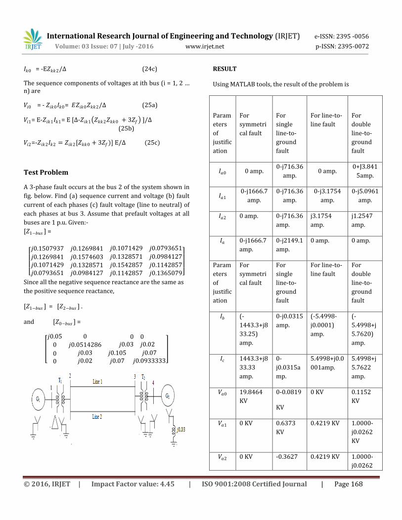
Test Problem
A 3-phase fault occurs at the bus 2 of the system shown in
fig. below. Find (a) sequence current and voltage (b) fault
current of each phases (c) fault voltage (line to neutral) of
each phases at bus 3. Assume that prefault voltages at all
buses are 1 p.u. Given:-
[𝑍1−𝑏𝑢𝑠 ] =
𝑗0.1507937 𝑗0.1269841 𝑗0.1071429 𝑗0.0793651
𝑗0.1269841 𝑗0.1574603 𝑗0.1328571 𝑗0.0984127
𝑗0.1071429𝑗0.0793651
𝑗0.1328571𝑗0.0984127
𝑗0.1542857 𝑗0.1142857𝑗0.1142857 𝑗0.1365079
Since all the negative sequence reactance are the same as
the positive sequence reactance,
[𝑍1−𝑏𝑢𝑠 ] = [𝑍2−𝑏𝑢𝑠 ] . and [𝑍0−𝑏𝑢𝑠 ] =
𝑗0.05 0 0 00 𝑗0.0514286 𝑗0.03 𝑗0.02
00
𝑗0.03𝑗0.02
𝑗0.105𝑗0.07
𝑗0.07𝑗0.0933333
RESULT
Using MATLAB tools, the result of the problem is
Param
eters
of
justific
ation
For
symmetri
cal fault
For
single
line-to-
ground
fault
For line-to-
line fault
For
double
line-to-
ground
fault
𝐼𝑎0 0 amp. 0-j716.36
amp. 0 amp.
0+J3.841
5amp.
𝐼𝑎1 0-j1666.7
amp.
0-j716.36
amp.
0-j3.1754
amp.
0-j5.0961
amp.
𝐼𝑎2 0 amp. 0-j716.36
amp.
j3.1754
amp.
j1.2547
amp.
𝐼𝑎 0-j1666.7
amp.
0-j2149.1
amp.
0 amp. 0 amp.
Param
eters
of
justific
ation
For
symmetri
cal fault
For
single
line-to-
ground
fault
For line-to-
line fault
For
double
line-to-
ground
fault
𝐼𝑏 (-
1443.3+j8
33.25)
amp.
0-j0.0315
amp.
(-5.4998-
j0.0001)
amp.
(-
5.4998+j
5.7620)
amp.
𝐼𝑐 1443.3+j8
33.33
amp.
0-
j0.0315a
mp.
5.4998+j0.0
001amp.
5.4998+j
5.7622
amp.
𝑉𝑎0 19.8464
KV
0-0.0819
KV
0 KV 0.1152
KV
𝑉𝑎1 0 KV 0.6373
KV
0.4219 KV 1.0000-
j0.0262
KV
𝑉𝑎2 0 KV -0.3627 0.4219 KV 1.0000-
j0.0262

International Research Journal of Engineering and Technology (IRJET) e-ISSN: 2395 -0056
Volume: 03 Issue: 07 | July -2016 www.irjet.net p-ISSN: 2395-0072
© 2016, IRJET | Impact Factor value: 4.45 | ISO 9001:2008 Certified Journal | Page 169
KV KV
𝑉𝑎 19.8464
KV
24.4906
KV
0.8437 KV 2.1152-
j0.0525
KV
𝑉𝑏 (-9.9223-
j17.1870)
KV
(-27.844-
j110.00)
KV
-0.4219 KV 0 KV
𝑉𝑐 (-
9.9223+j1
7.1870)
KV
(-
27.848+j
110.00)
KV
-0.4219 KV 0 KV
RESULT ANALYSIS
It is evident from the result that a 3-phase fault is the most
dangerous one and it has larger magnitude of current than
other types of fault. Also among the unsymmetrical, line-
to-line fault because of absence of zero sequence network
as there is no path to ground ,it has higher magnitude of
current with respect to single line-to-ground fault and
double line-to-ground fault. This could be matched with
theoretical equation (16) as well, where zero sequence
networks is not there in denominator. The magnitude of
Double line-to-ground fault lies between single line-to-
ground fault and line –to-line fault i.e. less than line-to-line
fault and more than single line-to-ground fault. As far as
voltage is concerned line-to-line voltage has least voltage
among the unsymmetrical faults.
Also, data and analysis came same when the fault occurred
at bus 3 and parameters calculated at bus 2.
CONCLUSION
This paper is basically related with finding the fault that
occurs in power system using digital approach and
through MATLAB programming and it is concluded that
the evaluation of fault is very important part of power
system analysis for stable and economic operations of
power system network and also because it provide data
such as voltage and currents which are necessary in
designing the protective schemes of power system. The
calculations are done theoretically and also by MATLAB
programming. Both results are found equal, so this type of
digital fault calculation is very useful.
REFERENCES
[1] D P Kothari and I J Nagrath, “Unsymmetrical Fault Analysis”,in Power System Engineering,2nd ed.,Tata McGraw Hill,2011,pp.525-530.
[2] C.L.Wadhwa, “Symmetrical Components and Fault Calculation’’,in Electrical Power System,6th ed., New Age International Limited, 2010, pp.312-329.
[3] J.B.Gupta, “Unsymmetrical Fault Analysis”,in A course in Power Systems,11th ed.,S.K.Kataria & Sons,2013,pp.80-83.
[4] P.S.R. Murthy, “Unbalaced Fault Analysis”,in Power System Analysis,BS publication,2007,pp. 241-243.
[5] Md. Fadli Bin Samsudin, “Transmissions Line Fault Analysis Using Bus Impedence Matrix,”Elect. Res. Lab ,Universiti Technologi Malaysia,Final Rep.,May 2011.
[6] Sushma Ghimire,"Analysis of fault location methods on transmission line,”M.S. thesis,Dept. Elect. Eng.,University of New Orleans,New Orleans,Louisiana,United states,2011.
BIOGRAPHIES
Mr. PRALAY ROY Assistant Professor of Electrical Engineering Dept., Siliguri Institute of Technology, Sukna, Darjeeling. Area of Interest-Power system, Electrical Machine, Power Electronics, Analog Electronics.
Mr. Shubham Kumar Gupta 3rd year B.TECH student, 2016 of Dept. of Electrical Engineering, Siliguri Institute of Technology, Sukna,Darjeeling. Area of Interest- Analog Electronics, Electrical Machines, Power System, Basic Electrical Embedded System.