digital systems lecture notes -...
TRANSCRIPT

Digital SystemsLecture notes
Dr Peadar Grant
2017/18 Semester 1Updated December 12, 2017
Contents
1 Computer components . . . . . . . . . . . . 1-11.1 Key components . . . . . . . . . . . . 1-11.2 Long term storage . . . . . . . . . . . . 1-11.3 Remote communications . . . . . . . . 1-1
2 Electrical basics . . . . . . . . . . . . . . . 2-12.1 Key quantities . . . . . . . . . . . . . . 2-12.2 Ohm’s law . . . . . . . . . . . . . . . . 2-12.3 Power law . . . . . . . . . . . . . . . . 2-12.4 Combining the two laws . . . . . . . . 2-22.5 Mains electricity . . . . . . . . . . . . 2-2
3 Units and prefixes . . . . . . . . . . . . . . 3-13.1 Units . . . . . . . . . . . . . . . . . . . 3-13.2 Magnitude . . . . . . . . . . . . . . . . 3-13.3 Engineering units . . . . . . . . . . . . 3-13.4 Calculator usage . . . . . . . . . . . . . 3-2
4 Digital logic systems . . . . . . . . . . . . . 4-14.1 System . . . . . . . . . . . . . . . . . . 4-14.2 Signals . . . . . . . . . . . . . . . . . . 4-14.3 Digital System . . . . . . . . . . . . . 4-14.4 Truth table . . . . . . . . . . . . . . . . 4-14.5 Binary logic circuits . . . . . . . . . . . 4-24.6 Specifying functionality . . . . . . . . . 4-2
5 Logic gates . . . . . . . . . . . . . . . . . . 5-15.1 Basic logical operations . . . . . . . . . 5-15.2 Logic circuits . . . . . . . . . . . . . . 5-25.3 Intermediate operations . . . . . . . . . 5-25.4 Analysis and synthesis . . . . . . . . . 5-2
6 Boolean Algebra . . . . . . . . . . . . . . . 6-16.1 Simplification . . . . . . . . . . . . . . 6-16.2 Commutative . . . . . . . . . . . . . . 6-16.3 Associative . . . . . . . . . . . . . . . 6-16.4 De Morgan’s Laws . . . . . . . . . . . 6-16.5 Identities . . . . . . . . . . . . . . . . 6-16.6 Distributive laws . . . . . . . . . . . . 6-1
7 Real-world data . . . . . . . . . . . . . . . 7-17.1 Bit . . . . . . . . . . . . . . . . . . . . 7-17.2 Multi-state data . . . . . . . . . . . . . 7-17.3 Large numbers of bits . . . . . . . . . . 7-17.4 Byte . . . . . . . . . . . . . . . . . . . 7-2
8 Communication systems . . . . . . . . . . . 8-18.1 Communications system . . . . . . . . 8-18.2 Serial and parallel transmission . . . . . 8-18.3 Performance . . . . . . . . . . . . . . . 8-1
9 Binary numbers . . . . . . . . . . . . . . . 9-19.1 Number systems . . . . . . . . . . . . . 9-1
9.2 Base-2 numbers . . . . . . . . . . . . . 9-1
10 Fractional numbers . . . . . . . . . . . . . 10-110.1 Conversions to decimal . . . . . . . . . 10-110.2 Conversions from decimal . . . . . . . 10-110.3 Direct conversions . . . . . . . . . . . 10-2
11 Number representation . . . . . . . . . . . 11-111.1 Storage . . . . . . . . . . . . . . . . . 11-111.2 Unsigned integers . . . . . . . . . . . . 11-111.3 Signed integers . . . . . . . . . . . . . 11-1
12 Networks . . . . . . . . . . . . . . . . . . . 12-112.1 Topology . . . . . . . . . . . . . . . . 12-112.2 Transmission types . . . . . . . . . . . 12-112.3 7-layer model . . . . . . . . . . . . . . 12-212.4 Addresses . . . . . . . . . . . . . . . . 12-2
13 Hexadecimal . . . . . . . . . . . . . . . . . 13-113.1 Hexadecimal . . . . . . . . . . . . . . 13-113.2 Decimal conversion . . . . . . . . . . . 13-113.3 Binary conversion . . . . . . . . . . . . 13-1
14 Routing . . . . . . . . . . . . . . . . . . . . 14-114.1 Interconnecting LANs . . . . . . . . . 14-114.2 Routing . . . . . . . . . . . . . . . . . 14-114.3 Subnet mask . . . . . . . . . . . . . . . 14-1
15 Broadband . . . . . . . . . . . . . . . . . . 15-115.1 Key metrics . . . . . . . . . . . . . . . 15-115.2 Common connection methods . . . . . 15-1
16 Operating systems . . . . . . . . . . . . . . 16-116.1 Main tasks . . . . . . . . . . . . . . . . 16-116.2 Components . . . . . . . . . . . . . . . 16-116.3 Multitasking . . . . . . . . . . . . . . . 16-1
17 User interfaces . . . . . . . . . . . . . . . . 17-1
18 Scripting . . . . . . . . . . . . . . . . . . . 18-1
19 Name resolution . . . . . . . . . . . . . . . 19-1
20 DNS . . . . . . . . . . . . . . . . . . . . . . 1
i
Chapter 1Computer components
Most digital devices, whether very simple (like an oventimer) or very complex (like a supercomputer) willshare a number of key traits and components.
1.1 Key components
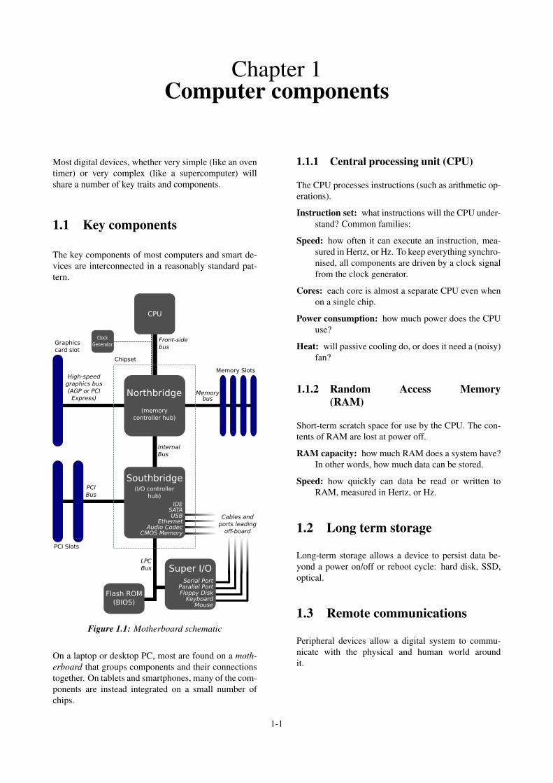
The key components of most computers and smart de-vices are interconnected in a reasonably standard pat-tern.
CPU
Flash ROM
(BIOS)
Super I/OSerial Port
Parallel PortFloppy Disk
KeyboardMouse
Northbridge
(memory
controller hub)
Southbridge(I/O controller
hub)
IDESATAUSB
EthernetAudio Codec
CMOS Memory
Clock
GeneratorGraphics
card slot
High-speed
graphics bus
(AGP or PCI
Express)
Chipset
Front-side
bus
Memorybus
Memory Slots
PCI
Bus
PCI Slots
LPC
Bus
Internal
Bus
Cables and
ports leading
off-board
Figure 1.1: Motherboard schematic
On a laptop or desktop PC, most are found on a moth-erboard that groups components and their connectionstogether. On tablets and smartphones, many of the com-ponents are instead integrated on a small number ofchips.
1.1.1 Central processing unit (CPU)
The CPU processes instructions (such as arithmetic op-erations).
Instruction set: what instructions will the CPU under-stand? Common families:
Speed: how often it can execute an instruction, mea-sured in Hertz, or Hz. To keep everything synchro-nised, all components are driven by a clock signalfrom the clock generator.
Cores: each core is almost a separate CPU even whenon a single chip.
Power consumption: how much power does the CPUuse?
Heat: will passive cooling do, or does it need a (noisy)fan?
1.1.2 Random Access Memory(RAM)
Short-term scratch space for use by the CPU. The con-tents of RAM are lost at power off.
RAM capacity: how much RAM does a system have?In other words, how much data can be stored.
Speed: how quickly can data be read or written toRAM, measured in Hertz, or Hz.
1.2 Long term storage
Long-term storage allows a device to persist data be-yond a power on/off or reboot cycle: hard disk, SSD,optical.
1.3 Remote communications
Peripheral devices allow a digital system to commu-nicate with the physical and human world aroundit.
1-1

Chapter 2Electrical basics
2.1 Key quantities
Voltage (V) the potential difference (like water pres-sure) between two points. Measured in Volts, sym-bol V using a voltmeter.
Current (I) the amount of charge (like water flow)that’s flowing through a wire or component. Mea-sured in Amperes, symbol A, using an ammeter.
Resistance (R) the difficulty that a componentpresents to current flowing in response to avoltage across it. Similar to a constriction in awater pipe. Measured in Ohm, symbol Ω, usingan ohmmeter.
Power (P) the rate at which a system can convert oneform of energy into another. Measured in Watt,symbol W, using a wattmeter.
The functions of a voltmeter, ammeter and ohmmeterare often combined into a common cheap measurementinstrument called a multimeter.
2.2 Ohm’s law
Ohm’s law relates voltage, current and resis-tance.
V = R · I (2.1)
Example 2.1 (Ohm’s law). When the current flowingthrough a component with resistance 4 Ω is measuredwith an ammeter, it was found to be 5 A. What voltageexists across the two terminals of the component?
Solution: Use Equation 2.1 directly:
V = R · I= 4 ·5= 20V
2.2.1 Manipulating Ohm’s law
Although it’s easiest to remember in the V = R · I form,it is straightforward to rearrange it to get either current
or resistance:
⇒ I =VR
(2.2)
⇒ R =VI
(2.3)
Example 2.2 (Ohm’s law). A light bulb is connected toa 12 V battery. The current flowing through the lightbulb is 2 A. What is the resistance of the light bulb?
Solution: Rearrange Equation 2.1 to make R the subjectof the formula, i.e. Equation 2.3:
R =122
= 6Ω
2.3 Power law
Power is related to voltage and current, in a similarmanner to Ohm’s law.
P =V · I (2.4)
Example 2.3 (Power calculation). A graphics card ispowered by a 12 V supply and the current flowing intothe card is measured as 8 A. Calculate the power con-sumed by the graphics card.
Solution: We just use the power relation Equation 2.4directly to get:
P =V · I= 12 ·8= 96W
2.3.1 Manipulating the power law
Just as in the case of Ohm’s law, the power relationP =V · I can be rearranged to give either voltage or cur-rent:
⇒V =PI
(2.5)
⇒ I =PV
(2.6)
2-1
CHAPTER 2. ELECTRICAL BASICS 2-2
Example 2.4 (Power calculation). A 24 V power supplyis delivering 120 W. Calculate the current.
Solution: Re-arrange Equation 2.4 to make I the subjectof the formula, as in Equation 2.6.
I =PV
=12024
= 5A
2.4 Combining the two laws
Ohm’s law and the power law can be combined if nec-essary:
1. See if the quantity you need can be determined us-ing either the power relation or ohm’s law.
2. If not, choose a form of either in terms of the de-sired quantity.
3. One of the variables on the right will be unknown,so choose a form of the other law for it.
4. Simplify the right-hand side using algebra.
5. Substitute in the numbers for the variables.
Example 2.5 (Combined Ohm and power relation forpower). Calculate the power converted to heat in an 8 Ω
resistor when a voltage of 4 V is applied across it.
Solution: In this case, we want P, which requires know-ing V and I, Equation 2.4. We don’t know I but we canuse Ohm’s law to get it from Equation 2.2, so we get
P =V · I
=V ·(
VR
)=
V 2
R
=42
8
=168
= 2W
Example 2.6 (Combined Ohm and power relation forcurrent). Calculate the current flowing through a 20 Ω
resistor that is producing 500 W of heat.
I =PV
=P
R · I
⇒ I2 =PR
⇒ I =
√PR
=
√50020
=√
25= 5A
2.5 Mains electricity
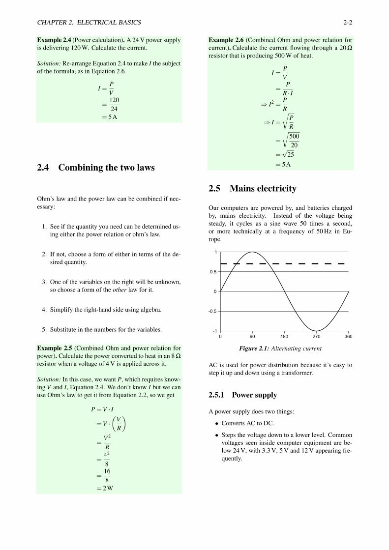
Our computers are powered by, and batteries chargedby, mains electricity. Instead of the voltage beingsteady, it cycles as a sine wave 50 times a second,or more technically at a frequency of 50 Hz in Eu-rope.
1
0.5
0
-0.5
-1
900 180 270 360
Figure 2.1: Alternating current
AC is used for power distribution because it’s easy tostep it up and down using a transformer.
2.5.1 Power supply
A power supply does two things:
• Converts AC to DC.
• Steps the voltage down to a lower level. Commonvoltages seen inside computer equipment are be-low 24 V, with 3.3 V, 5 V and 12 V appearing fre-quently.

Chapter 3Units and prefixes
Technical mathematics needs units (to differentiatereal-world quantities from each other) and prefixes (sowe can easily discuss very large and very small num-bers easily).
3.1 Units
Apples aren’t the same as oranges — that’s why weneed units when doing technical mathematics.
Quantity Symbol Unit Abbreviation
Distance metre mTime t second sVoltage V volt VCurrent I ampere APower P watt WResistance R ohm Ω
Table 3.1: SI units
One way to check that our calculations are correct, par-ticularly when manipulating equations like Ohm’s lawis to check that the units divide out.
3.2 Magnitude
It would be silly to try and quantify the distance fromDundalk to Brisbane in terms of metres. Similarly, itwould be odd to discuss the duration of a camera flashor a spaceflight to Mars in terms of seconds.
3.2.1 Scientific notation
One way to make numbers easier to understand is to usescientific notation, where a number x is expressed as amantissa m and exponent n:
x = m×10n (3.1)
We usually choose m and n so that 1≤ m < 10.
Scientific notation is not necessarily easy to work withwhen speaking or writing, so we instead use engineer-ing units.
3.2.2 Engineering notation
Engineering notation is the same as scientific notationin principle, except that we restrict n to be multiples of3, including zero. These correspond to powers of 10that area multiples of three, e.g. 10−9, 106 etc.
x = m×10n (3.2)
m is now chosen so that 1≤ m≤ 1000.
3.3 Engineering units
To make things easier to discuss and understand, we of-ten use standard prefixes to denote specific powers often, Table 3.2, that correspond to those from engineer-ing notation.
Prefix Same as Common name
P 1015 PetaT 1012 TeraG 109 GigaM 106 Megak 103 Kilo
100 1
m 10−3 milliµ 10−6 micron 10−9 nanop 10−12 picof 10−15 femto
Table 3.2: Positive unit prefixes (decimal)
Some things to note:
• The k in kilo is lowercase.
• Micro is denoted by the greek letter µ , pronounced“mu”. Most computers don’t use greek letters, sowe use u.
3.3.1 Mental conversions
There are two simple rules to follow for mental conver-sions:
Changing to the next largest unit: divide by 1000.
3-1
CHAPTER 3. UNITS AND PREFIXES 3-2
Changing to the next smallest unit: multiply by1000.
Example 3.1 (Unprefixed to prefixed quantity). Anelectric passenger train consumes 1715000 W of powerfrom the overhead line. Express the power inmegawatts.
Solution:
P = 1715000W
=1715000
1000kW
= 1715kW
=17151000
MW
= 1.715MW
3.4 Calculator usage
To make calulations in engineering units relativelyeasy:
1. Always manipulate formulas in symbolic formrather than putting in numbers. Only put in thenumbers when your formula is in its final form.
2. Put your calculator into ENG mode.
3. Enter all prefixed quantities in their correspond-ing engineering form using the EXP key from Ta-ble 3.2.
4. Use the TAB function to truncate the display to 2-3significant figures (after the decimal point).
5. You can then write the answer using the letter pre-fix corresponding to the displayed power of 10from Table 3.2.
Example 3.2 (Engineering mode on calculator). Alarge piece of equipment consumes 460 kW from a230 V power supply. What is the current drawn?
Solution: We’ll use Ohm’s law so that
I =PV
Putting your calculator in ENG mode, you can then en-ter:
460×103÷230
The answer should display as 200×103. We know thatthe unit for current is the amp, and from Table 3.2 weknow that 103 is k, so our answer is 200 kA.

Chapter 4Digital logic systems
4.1 System
A system produces one or more outputs as a functionof one or more inputs.
output = f (input) (4.1)
Systeminput(s) output(s)
Figure 4.1: Digital system with inputs and outputs
The simplest system has only one input and only oneoutput.
4.2 Signals
Signals represent real-world data in electrical (or other)form. There are two key types of signals:
Analogue signal can take on any value within a spe-cific range. (Time, Distance, Temperature etc)
Digital signal can take on one of a number of allowedvalues. (Traffic light state, Electrical switch)
4.3 Digital System
A digital system, often called a digital logic system orlogic circuit produces one or more digital outputs as afunction of one or more digital inputs.
4.3.1 Combinational vs. sequential
Most logic circuits can be classified as either combina-tional or sequential:
Combinational depends only on current inputs.
Sequential depends on current inputs and history.
This course will mainly consider basic combinationallogic circuits.
4.4 Truth table
A truth table is one way to specify what a digital logicsystem does. The truth table of a digital system liststhe output for every possible input. The arrangement oftruth table is always:
1. Input(s) go on the left.
2. Output(s) go on the right.
3. Each row lists different a input combination.
Example 4.1 (Truth table). A self-driving car controlsystem should drive when the traffic light is green oramber and only when no pedestrian is in its path. If thetraffic light is red or there is a pedestrian in front, themotor should stop. Describe this system’s functionalityin a truth table.
Solution: We list out all the possible combinationsof the inputs. The traffic light is in one of 3states, and the pedestrian is either present or not.
Traffic light Pedestrian Motor
Green No DriveGreen Yes StopAmber No DriveAmber Yes StopRed No StopRed Yes Stop
4.4.1 Rows
From combination theory, the number of rows in a truthtable is the product of the number of states that eachinput can take on. The hash-symbol (#) means “numberof”.
4.4.2 Columns
The number of columns is simply the sum of the num-ber of inputs and the number of outputs.
#columns = #outputs+#inputs (4.2)
4-1

CHAPTER 4. DIGITAL LOGIC SYSTEMS 4-2
Example 4.2 (Columns in a truth table). A logic circuithas three inputs and two outputs. Find the number ofcolumns in the truth table.
Solution: Each input requires a column, as does eachoutput. We use Equation 4.2:
#columns = #outputs+#inputs= 2+3= 5
4.5 Binary logic circuits
A binary digital logic system is one where the input andoutput signals can all only take on one of two possiblevalues:
• One of the possible values is false, or 0.
• The other is true, or 1.
The real-world meaning of 0 and 1 need to be definedsomewhere for a system to be actually built. Differentsignals in the one system may map 0 and 1 to differ-ent things. A binary signal is commonly called a bit.From now on, when we talk about logic circuits, weassume that we are dealing with a binary digital logiccircuit.
4.5.1 Rows
The hash-symbol (#) means “number of”.
#rows = 2(#inputs) (4.3)
Example 4.3 (Rows in a truth table). A logic circuit hasthree inputs and two outputs. Find the number of rowsin the truth table.
Solution: The number of rows depends solely on thenumber of inputs, the number of outputs does not mat-ter. We use Equation 4.3:
#rows = 23
= 8
4.5.2 Computing powers of 2
You must be comfortable with powers of 2. It’s betterto work them out than to try to learn off a list of them.First, remember that
x0 = 1 ∀x (4.4)
so anything raised to the power of zero is one. Then justapply the rule
xn = x · x(n−1) (4.5)
Example 4.4 (Powers of 2). Find 24
Solution: Determine 20 using Equation 4.4, then multi-ply by 2 at each step as in Equation 4.5:
20 = 1
21 = 2 ·1 = 2
22 = 2 ·2 = 4
23 = 2 ·4 = 8
24 = 2 ·8 = 16
4.5.3 Input combinations
It’s best to list input combination systematically. It’ssuggested that you “count in base 2” upwards from theright hand side of the inputs:
a b c x
0 0 0 00 0 1 00 1 0 00 1 1 0... ... ... ...1 1 1 1
Table 4.1: Truth table for the circuit abc
4.6 Specifying functionality
There are a few ways we can specify the functionalityof a digital system:
Natural language works well for simple systems, butbecomes unwieldy and imprecise with larger sys-tems.
Truth tables give a full description of a system’s func-tionality. They are able to encode the functionalityof systems very precisely but can become large.
Boolean algebra is where we break down a system’sfunctionality into a set of interconnected elemen-tary operations, and describe them mathematicallyusing familiar symbols.

Chapter 5Logic gates
5.1 Basic logical operations
Digital logic circuits can be broken down into a set ofinterconnected logic operations, called gates. Three ba-sic logic operations underlie all digital systems, AND,OR and NOT.
5.1.1 NOT
Simplest logical operation, takes one input and pro-duces one output (unary), maps 0 to 1 and 1 to 0:
p = 0⇒NOT p = 1 (5.1)p′ = 1 (5.2)p = 1 (5.3)
p = 1⇒NOT p = 0 (5.4)p′ = 0 (5.5)p = 0 (5.6)
We often want to show logic circuits diagramattically.The NOT operator is shown in Figure 5.1.
p NOT p
Figure 5.1: NOT gate symbol
The truth table for a NOT gate is shown in Ta-ble 5.1
a a′
0 11 0
Table 5.1: Truth table for NOT gate
5.1.2 AND
For the AND gate, the output will be true if and only ifboth p and q are true, otherwise it will be false.
p
qp AND q
Figure 5.2: AND gate symbol
The truth table for an AND gate is shown in Ta-ble 5.2
a b ab
0 0 00 1 01 0 01 1 1
Table 5.2: Truth table for AND gate
There are a number of ways we can write the AND op-eration. Often we use the dot (similar to numerical mul-tiplication):
p AND q = p ·q (5.7)
The AND operation is commutative, meaning that theorder of the inputs doesn’t affect the result:
p AND q = q AND p (5.8)
5-1

CHAPTER 5. LOGIC GATES 5-2
5.1.3 OR
For the OR gate, the output will true if either or both ofp and q are true. If both p and q are false, the outputwill be false.
p
qp OR q
Figure 5.3: OR gate symbol
The truth table for an OR gate is shown in Table 5.3.
a b ab
0 0 00 1 11 0 11 1 1
Table 5.3: Truth table for OR gate
The OR operation is often written using the plussign:
p OR q = p+q (5.9)
Note that this means in boolean logic that:
1+1 = 1 (5.10)
Like the AND gate, the OR gate is also commutative,meaning that the order of the inputs doesn’t affect theresult:
p OR q = q OR p (5.11)
5.2 Logic circuits
The elementary logic operations can be combined to-gether in what are called Logic circuits. Gates receiveinput from external inputs, and from the outputs ofother gates.
5.2.1 Guidelines
• Horizontal flow of signals.
• Inputs on the left, outputs on the right.
• Any value can be connected to multiple inputs.
5.2.2 Rules
• No unconnected inputs. Unconnected inputs 6=0! If an input is unconnected it’s value is unde-fined.
• Cannot connect two or more outputs together.
• All external inputs and outputs labelled.
Example 5.1 (Logic circuit). Draw the logic circuit thatimplements the boolean expression:
x = (a ·b)′
Solution: Looking at the above expression, we have theAND operation a ·b, which is input to a NOT operation.
a
bx
5.3 Intermediate operations
It’s often useful to show the intermediate operations in atruth table, by inserting additional columns between theinputs (on the left) and the outputs (on the right).
Example 5.2 (Show intermediate operations). Show theintermediate operations for the equations:
x = (a ·b)′
Solution:a b a ·b (a ·b)′
0 0 0 10 1 0 11 0 0 11 1 1 0
5.4 Analysis and synthesis
There are two main activities involved with digital logiccircuits:
Synthesis taking a description of what the circuit doesin boolean algebra, and implementing it as logicgates.
Analysis looking at what an implemented logic circuitdoes, and writing its functionality in boolean alge-bra.

Chapter 6Boolean Algebra
6.1 Simplification
We’ve seen already that some expressions actually re-duce down to simpler equivalents, sometimes just 1 or0.
1. Construct Truth table and summarise output (ifpossible).
2. Apply laws and identities of boolean algebra.
6.2 Commutative
Commutativity imples that we can interchangeoperands without affecting the result:
a+b = b+a (6.1)ab = ba (6.2)
6.3 Associative
Associativity means that we can do either side of anequivalant-precedence operation first:
a+(b+ c) = (a+b)+ c (6.3)a(bc) = (ab)c (6.4)
6.4 De Morgan’s Laws
De Morgan’s laws mainly allow us to transform opera-tions involving negation from an AND to an OR opera-tion:
(a+b)′ = a′b′ (6.5)(ab)′ = a′+b′ (6.6)
6.5 Identities
There are a few identities that you need to watch outfor.
6.5.1 Redundant inputs
Sometimes in an expression one of the inputs will be-come redundant, often as a function of previous simpli-fication.
a(a+b) = a (6.7)a+ab = a (6.8)
a+0 = a (6.9)a ·1 = a (6.10)
a+a = a (6.11)aa = a (6.12)
(a′)′ = a (6.13)
6.5.2 Evaluating to true
Some boolean logic expressions always evaluate totrue, making the actual value(s) of the input(s) irrele-vant.
a+1 = 1 (6.14)a+a′ = 1 (6.15)
6.5.3 Evaluating to false
Similarly, some boolean logic expressions will alwaysevaluate to false.
a ·0 = 0 (6.16)a ·a′ = 0 (6.17)
6.6 Distributive laws
The distributive laws allow us to convert betweenbracketed and bracketed equivalents:
a(b+ c) = ab+ac (6.18)a+bc = (a+b)(a+ c) (6.19)
6-1

Chapter 7Real-world data
Our digital systems are only worth using if they canstore and process real-world data.
7.1 Bit
A bit is the smallest unit of binary data.
• Bit allows us to store 1 of two states, i.e. true/false
• This can be stored electrically, mechanically etc.
The problem is that most real world data has more thantwo states.
7.2 Multi-state data
From combination theory, n bits, each of which has twopossible states, can together represent 2n states.
Example 7.1 (States per bit). How many states can 1,2, 3 bits represent?
1 bit: ⇒ 21 = 2 (7.1)
2 bits: ⇒ 22 = 4 (7.2)
3 bits: ⇒ 23 = 8 (7.3)
So, adding one additional bit to a group of bits dou-bles the number of states that the group can repre-sent.
7.2.1 Bits required
Given n states, the minimum number of bits nb neces-sary to represent all states is:
nb = dlog2 ne (7.4)
The ceiling operator d...e means the next integer notsmaller than:
Example 7.2 (Ceiling operator). Calculate d2.6e
Solution:
d2.6e= 3 (7.5)
Unless your calculator can directly work out logs to thebase of 2, it’s often best to write out a table of powersof 2, as in subsection 4.5.2, and work from that.
Example 7.3 (Bits required). Calculate the minimumnumber of bits needed to represent the uppercase lettersA to Z, the digits 0-9, the period, comma and space.
Solution:
nb = dlog2(26+10+3)e≈ d5.17e= 6
7.3 Large numbers of bits
As we can see from Example 7.4, we often end upneeding large numbers of bits for typical real-worlddata:
Example 7.4. A greyscale (no colour) image is repre-sented as a grid of 640 by 480 pixels, where each pixelcan take on 256 different brightness levels from blackto white. Calculate the number of bits required to rep-resent this image.
Solution: First, we need to know how many bits a singlepixel needs:
nb = dlog2 256e= 8
So we need 8 bits per pixel, giving
bits required = 640×480×8= 2457600
7.3.1 Binary prefixes
As with decimal quantities, we often use the same pre-fix letters (k, M, G, T, P) to mean slightly differentthings when we’re discussing bits rather than other dec-imal quantities. The reason for this will become moreapparent when we look at binary numbers.
7.3.2 Using binary prefixes
When converting among different quantities, the rulesare similar to those for decimal quantities:
Changing to the next largest unit: divide by 1024.
7-1

CHAPTER 7. REAL-WORLD DATA 7-2
Prefix Same as Common name
P 250 = (210)5 PetaT 240 = (210)4 TeraG 230 = (210)3 GigaM 220 = (210)2 Megak 210 = 1024 kilo
Table 7.1: Positive unit prefixes (binary)
Changing to the next smallest unit: multiply by1024.
Here, we usually try to ensure that the prefixed value isless than 1024.
Example 7.5 (Bits to kilobits). Express 2048 bits in kb.
Solution:
1 kb = 1024 bits
⇒ 2048 bits =20481024
kb
= 2 kb
7.4 Byte
A byte is conventionally defined as a group of 8bits.
• Sizing is mainly historical!
• ASCII set fits within 7 bits, leaving 1 spare.
• Computer CPUs can address individual bytes inmemory, not bits.
7.4.1 Byte storage requirements
Normally, we assume a question asked in bytes to meancomplete bytes.

Chapter 8Communication systems
8.1 Communications system
A simple point-to-point communication system sends amessage from point A to point B, Figure 8.1.
Figure 8.1: Communication system components
Message data (text, audio, video, or images)
Sender the device that is sending the data
Receiver the device that receives the message
Transmission medium is the physical path the mes-sage takes from the sender to the receiver.
Protocol a set of rules that govern communication
8.2 Serial and parallel transmis-sion
Some systems are capable of sending multiple signalssimultaneously (parallel), whilst others send one at atime (serial).
D0D1D2D3D4D5D6D7
ReceiverParallel InterfaceSender
D0D1D2D3D4D5D6D7 0 (MSB)
1 (LSB)
110001
Serial Interface
DIDO1
(MSB)
D0 D1 D2 D3 D4 D5 D6 D71 0 0 0 1 1 0
(LSB)
Sender Receiver
Example transfers of 01100011
Figure 8.2: Serial vs parallel transmission
8.3 Performance
We use a number of metrics to quantify how well a com-munication system performs:
Data rate (or bit rate) under continuous load is usu-ally the most important performance indicator of acommuniation system.
Latency: how long does it take for the first bit to getfrom the input to the output?
Reliability: does every message sent in get delivered,or are some lost?
Jitter: does the system delay every message by thesame amount?
8-1

Chapter 9Binary numbers
A lot of quantities we meet in life are numerical, likemoney, time, grades. To make sense of these, we usenumber systems.
9.1 Number systems
9.1.1 Notation
We’re most familiar with positional numbering systemsnowadays, although many ancient civilisations usednon-positional (additive, subtractive, others) numeralsystems. Digit position determines its weight:
1409⇒ digit 4 has greater value (9.1)1049⇒ digit 4 has less value (9.2)
The radix point indicates fractional parts:
10.3⇒ .3 is the fractional part (9.3)10.193⇒ .193 is the fractional part (9.4)
9.1.2 Number base
A base-n positional number system has n possiblenumerals to choose from at each position. For ex-ample in base-10, the numbers belong to the set0,1,2,3,4,5,6,7,8,9.
Sometimes we will see some other bases:
• Symbols/numerals used are entirely arbitary!
• Subsets/supersets of 0-10 often re-used.
9.1.3 Common bases
A number system can be constructed with any concie-veable base, but a few should be known:
Base-10 (Decimal): human civilisation for daily math.
Base-2 (Binary): majority of digital systems.
Base-8 (Octal): used by programmers to represent bi-nary quantities.
Base-16 (Hexadecimal): used by programmers to rep-resent binary quantities.
9.1.4 Spoken and written numbers
To avoid confusion, we often indicate the base follow-ing a number. For example, 10012 means that the nu-merals 1001 are in base-2, and is said as “1 0 0 1 to thebase 2 / in binary”.
10012 is not one thousand and one to the base 2! Whenworking in base-10, we usually drop the 10 subscriptunless actively doing a conversion.
9.2 Base-2 numbers
Humans work usually in base-10. Computers work inbinary, each position directly corresponds to bit values,using 0,1.
010 = 02 (9.5)110 = 12 (9.6)210 = 102 (9.7)310 = 112 (9.8)410 = 1002 (9.9)510 = 1012 (9.10)610 = 1102 (9.11)
9.2.1 Binary to decimal
Multiply each bit by the appropriate power of the base(from 0 on the right) and add.
Example 9.1 (Converting binary to decimal). Convert1101012 to decimal:
Solution:
1101012 (9.12)
= 1×25 +1×24 +0×23 +1×22 +0×21 +1×20
(9.13)
= 25 +24 +22 +20 (9.14)= 32+16+4+1 (9.15)= 5310 (9.16)
9-1

CHAPTER 9. BINARY NUMBERS 9-2
9.2.2 Decimal to binary
1. Repeatedly divide by 2 until the division gives azero whole-number part.
2. Read remainders from bottom up.
Example 9.2 (Decimal to binary). Convert 1910 to bi-nary.
Solution:
19÷2 = 912
⇒ 9÷2 = 412
⇒ 4÷2 = 202
⇒ 2÷2 = 102
⇒ 1÷2 = 012
Read the remainders backwards to get 100112.

Chapter 10Fractional numbers
10.1 Conversions to decimal
The conversion of binary/hex to decimal is the exactsame as before. Each fractional position right of theradix point is an increasing negative power of thebase.
10.1.1 Binary to decimal
To convert a base-2/binary number with a fractionalpart to decimal, we do the same as for integers, andjust continue on with negative powers right of radixpoint.
Example 10.1 (Fractional binary to decimal). Convert101.12 to decimal.
101.12 = 1×22 +0×21 +1×20 +1×2−1
= 22 +20 +2−1
= 4+1+0.5= 5.510
10.1.2 Hex to decimal
To convert a fractional hex number to decimal, wemultiply by negative powers of 16 right of radixpoint:
Example 10.2 (Fractional hex to decimal). ConvertA4.C16 to decimal.
A4.C16 = 10×161 +4×160 +12×16−1
= 160+4+0.75= 164.7510
10.2 Conversions from deci-mal
The conversions from decimal to binary/hex are a littlemore complicated. The method is slightly different leftand right of the radix point:
1. Convert the whole number part as before, bysuccessive division and reading the remaindersbackwards.
2. Convert the fractional part by successive multi-plication discarding integer portion until either:
(a) Fractional part is zero.
(b) Repeating pattern emerges.
(c) We have enough precision (won’t be an exactconversion!)
3. Read remainders forwards for fractional part.
10.2.1 Decimal to binary
Example 10.3 (Fractional decimal to binary). Convert3.812510 to binary. 310 = 112
0.8125×2 = 1.625fractional only: 0.625×2 = 1.25
0.25×2 = 0.50.5×2 = 1.0⇒ Stop
combining: 3.812510 = 112 +0.11012
= 11.11012
Sometimes (more often in fact) we won’t get a zero,so where do we stop? We stop when a patternemerges:
10.2.2 Decimal to hex
The exact same idea applies as for decimal to binary,only that the multiplication is by 16.
Example 10.4 (Fractional decimal to hex). Convert11.510 to hexadecimal. Whole number part 1110 = B16.
0.5×16 = 8.0 Stop⇒ 11.510 = B.8
In base-16, we more usually will end up with a repeat-ing fractional position (or pattern):
Example 10.5. Convert 13.810 to hex.
whole: 1310 = D16
fractional: 0.8×16 = 12.80.8×16 = 12.8
0.8⇒ same as before!13.810 = D.CC recurring
10-1

CHAPTER 10. FRACTIONAL NUMBERS 10-2
10.3 Direct conversions
As with whole numbers, it’s very easy to directly con-vert between binary and hex, much easier than conver-sions that involve decimals.
10.3.1 Hex to binary
Work outwards from the radix point.
Example 10.6 (Fractional hex to binary). Convert30.D616 to binary.
3⇒ 00110⇒ 0000D⇒ 11016⇒ 0110
⇒ 30.D616 = 110000.11010112
10.3.2 Binary to hex
Work outwards from the radix point, in groups of 4bits.
Example 10.7 (Fractional binary to hex). Convert101.1101112 to hex. First pad to groups of 4 bits:
101.110111 = 0101.11011100⇒ 01002 = 5
11012 = D
11002 = C

Chapter 11Number representation
11.1 Storage
When representing integers, n bits can represent 2n dif-ferent integers.
n−bit⇒ 2n different integers (11.1)
Example 11.1 (Bits storing integers). How many inte-gers can be stored by 4 bits.
Solution:
4bit⇒ 24 different integers (11.2)
11.1.1 Storage in bytes
Often because we tend to quantify memory in terms ofbytes, this calculation will be carried out in terms ofbytes. To do this, we just remember than 1 B is madeup of 8 bit.
n−B⇒ 2(1×n) different integers (11.3)
Example 11.2 (Bytes storing integers). Calculate thenumber of integers that can be stored in 1 and 2 bytes.
1B⇒ 2(1×8) = 256 integers (11.4)
2B⇒ 2(2×8) = 65536 integers (11.5)
11.2 Unsigned integers
Unsigned integers are those which are either positive orzero. For an unsigned integer n bits can store a numberbetween 0 and 2n−1.
n−bit⇒ 0≤ x≤ (2n−1) (11.6)
Example 11.3 (Unsigned integer range). Determine therange of unsigned integers that can be stored by 8 bits.
Solution:
8bit⇒ 0≤ x≤ (28−1) (11.7)⇒ 0≤ x≤ 255 (11.8)
11.2.1 Unsigned integer representa-tion
The procedure for storing an unsigned integer in n bitsor bytes is:
1. Ensure it fits within the range.
2. Convert to base-2.
3. Pad with zeros.
Example 11.4 (Representing a base-10 number inbase-2). Give the 4-bit unsigned representation of 510.
Solution:
4 bits⇒ 0≤ x≤(24−1
)(11.9)
⇒ 0≤ x≤ 15 (11.10)⇒ 5 within this range (11.11)
510 = 1012 (11.12)= 0101 (11.13)
11.3 Signed integers
Signed integers may be negative, positive or zero.For an n-bit signed integer, integers between −(2n−1)and 2n−1 − 1 can be stored, or expressed mathemati-cally:
n−bit⇒−(2n−1)≤ x≤ 2n−1−1 (11.14)
Example 11.5 (Signed integer range). Determine therange of numbers that can be stored as a 8-bit signedinteger.
Solution:
8bit⇒−(2n−1)≤ x≤ 2n−1−1 (11.15)
⇒−(28−1)≤ x≤ 28−1−1 (11.16)
⇒−(27)≤ x≤ (27−1) (11.17)⇒−128≤ x≤ 127 (11.18)
11.3.1 Signed integer to binary
The two’s compliment system stores a number usinga sign bit that is calculated by flipping the bits. Theprocedure is:
11-1

CHAPTER 11. NUMBER REPRESENTATION 11-2
1. Convert absolute value to n-bit representation.
2. Flip all the bits.
3. Add 1 to the number (deals with zero!)
Example 11.6 (Converting a signed integer to binary).Find the 4-bit representation of −5.
Solution:
510 = 1012 (11.19)fill out⇒ 0101 (11.20)
flip bits⇒ 1010 (11.21)add 1⇒ 1011 (11.22)
11.3.2 Binary to signed integer
Converting a binary number to its signed integerequivalent is accomplished using the following proce-dure:
1. Check if it’s signed or unsigned. If unsigned, justconvert as for any integer.
2. If starting bit is zero, just convert as for any integer.
3. Flip the bits.
4. Add 1.
When working with binary-stored integers, check ifthey’re signed or unsigned! There is no way of tellingfrom looking at the bits.
Chapter 12Networks
12.1 Topology
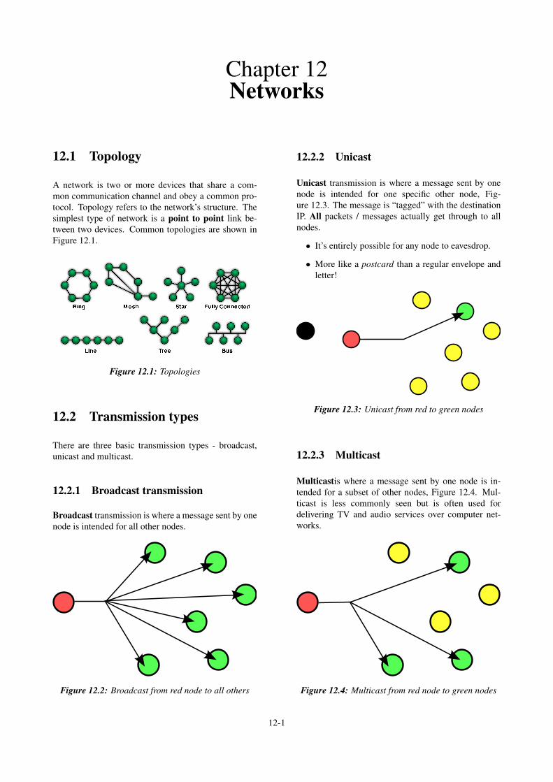
A network is two or more devices that share a com-mon communication channel and obey a common pro-tocol. Topology refers to the network’s structure. Thesimplest type of network is a point to point link be-tween two devices. Common topologies are shown inFigure 12.1.
Figure 12.1: Topologies
12.2 Transmission types
There are three basic transmission types - broadcast,unicast and multicast.
12.2.1 Broadcast transmission
Broadcast transmission is where a message sent by onenode is intended for all other nodes.
Figure 12.2: Broadcast from red node to all others
12.2.2 Unicast
Unicast transmission is where a message sent by onenode is intended for one specific other node, Fig-ure 12.3. The message is “tagged” with the destinationIP. All packets / messages actually get through to allnodes.
• It’s entirely possible for any node to eavesdrop.
• More like a postcard than a regular envelope andletter!
Figure 12.3: Unicast from red to green nodes
12.2.3 Multicast
Multicastis where a message sent by one node is in-tended for a subset of other nodes, Figure 12.4. Mul-ticast is less commonly seen but is often used fordelivering TV and audio services over computer net-works.
Figure 12.4: Multicast from red node to green nodes
12-1

CHAPTER 12. NETWORKS 12-2
12.3 7-layer model
The 7-layer model is a way to conceptually divide upthe complex interactions between different layers whena network is used to communicate from one node toanother:
Layer 7 — Application: message format, human-machine interface
Layer 6 — Presentation: coding data into 1s and 0s,encryption (if present), compression (if present)
Layer 5 — Session: authentication, permissions, ses-sion restoration
Layer 4 — Transport: end-to-end error control
Layer 3 — Network: network addressing, rout-ing/switching between circuits
Layer 2 — Data Link: Access and flow control, errordetection on single circuit
Layer 1 — Physical: bit stream: physical medium,method of representing bits.
The physical layer is the lowest level, and defines thingslike connectors and electrical voltages. The applicationlayer is the highest level, and refers to things like webbrowsers. You need to know the names and the func-tions of each layer. A handy memory aid:
People don’t need the seedy part (of)apples.
12.4 Addresses
12.4.1 MAC address
A hardware address is non-resettable and burned intoeach network interface at the factory. Most network de-vices use a 48-bit address, commonly called a MediumAccess Control, or MAC, address.
12.4.2 IP address
IP addresses are an example of a logical address, whichis one that makes sense to a network’s users or admin-istrators, Figure 12.6.
12.4.3 Address Resolution Protocol
1. Source checks own ARP cache for destination’sMAC address. If found, use it.
2. If not found, source broadcasts ARP request toentire LAN asking for destination’s MAC address.
1st octet 2nd octet 3rd octet 4th octet 5th octet 6th octet
6 octets
or
Organisationally UniqueIdentifier (OUI)
Network Interface Controller(NIC) Specific
3 octets 3 octets
b7 b6 b5 b4 b3 b2 b1 b0
8 bits
0:
1:
unicast
multicast
0:
1:
globally unique (OUI enforced)
locally administered
Figure 12.5: 48-bit MAC address
An IPv4 address
172 16 1254. . .
10101100 00010000 11111110 00000001 . . .
One byte Eight bits=
Thirty-two bits (4 x 8), or 4 bytes
(dotted-decimal notation)
Figure 12.6: IPv4 address
3. Each node sees request and checks if IP addressbelongs to it.
4. If it’s not its own IP, request is ignored.
5. Destination sends ARP reply with own h/w ad-dress back to source .
6. Source stores destination’s hardware address inARP cache.

Chapter 13Hexadecimal
13.1 Hexadecimal
Hexadecimal (Hex), or base-16, is an extremely com-mon representation used by humans to represent bi-nary numbers stored in digital systems. The hexadeci-mal number system borrows 6 alphabetic characters andadds them to the decimal numerals. Hex uses 0, 1, 2,3, 4, 5, 6, 7, 8, 9, A, B, C, D, E, F
910 = 916 (13.1)1010 = A16 careful! (13.2)1110 = B16 (13.3)1210 =C16 (13.4)1310 = D16 (13.5)1410 = E16 (13.6)1510 = F16 careful! (13.7)1610 = 1016 (13.8)
13.1.1 Zero prefixing
Don’t forget that in any numbering scheme, prefixing anumber with zero gives the same number:
Example 13.1 (Zero prefix).
010010 = 10010 (13.9)0AF16 = AF16 etc (13.10)
13.2 Decimal conversion
13.2.1 Hex to decimal
Same as base-10 to 2: multiply by positional power ofbase starting from 0 on right.
Example 13.2 (Hex to decimal). Convert 4EB16 to dec-imal.
4EB16 = 4×162 +14×161 +11×160 (13.11)= 4×256+14×16+11×1 (13.12)= 125910 (13.13)
13.2.2 Decimal to hex
Same as base-10 to 2: divide by 16 and read remain-ders backwards.
Example 13.3 (Decimal to hex conversion). Convert1710 to hexadecimal.
Solution: First take 17 and divide by 16:
17÷16 = 1116
(13.14)
1÷16 = 0116
(13.15)
Then read the remainders backwards to get 1116.
13.3 Binary conversion
It may surprise you to know that converting hex to/frombinary is a lot simpler than converting hex to/from dec-imal. This is because of an interesting property to dowith the number of bits needed to store a hex position,subsection 13.3.1
13.3.1 Bit storage requirement
By now we know that to store 16 states, 4 bits are re-quired:
bits required = dlog2 16e (13.16)= d4e (13.17)= 4 (13.18)
Note how log2 16 is exactly 4:
• 4 bits perfectly stores a hex position.
• no overspill into adjacent positions.
• no unused bit patterns.
Similarly to how we name 8 bits a byte, we call 4 bits anibble.
13-1
CHAPTER 13. HEXADECIMAL 13-2
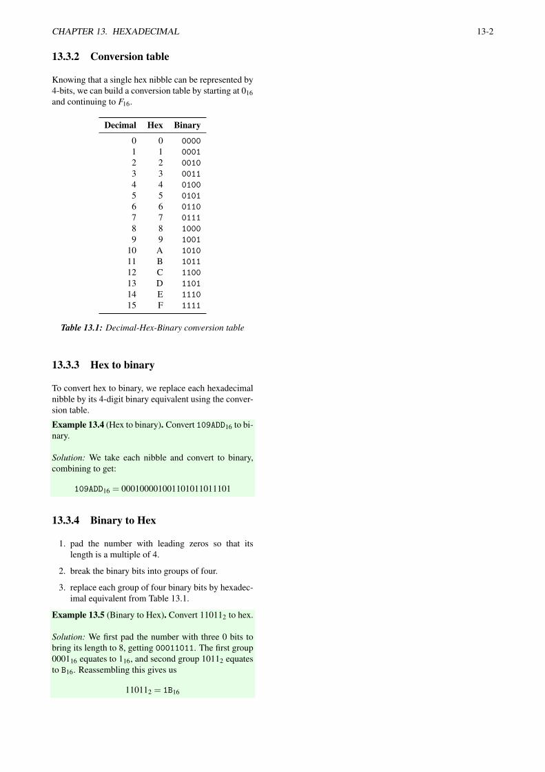
13.3.2 Conversion table
Knowing that a single hex nibble can be represented by4-bits, we can build a conversion table by starting at 016and continuing to F16.
Decimal Hex Binary
0 0 00001 1 00012 2 00103 3 00114 4 01005 5 01016 6 01107 7 01118 8 10009 9 1001
10 A 101011 B 101112 C 110013 D 110114 E 111015 F 1111
Table 13.1: Decimal-Hex-Binary conversion table
13.3.3 Hex to binary
To convert hex to binary, we replace each hexadecimalnibble by its 4-digit binary equivalent using the conver-sion table.
Example 13.4 (Hex to binary). Convert 109ADD16 to bi-nary.
Solution: We take each nibble and convert to binary,combining to get:
109ADD16 = 000100001001101011011101
13.3.4 Binary to Hex
1. pad the number with leading zeros so that itslength is a multiple of 4.
2. break the binary bits into groups of four.
3. replace each group of four binary bits by hexadec-imal equivalent from Table 13.1.
Example 13.5 (Binary to Hex). Convert 110112 to hex.
Solution: We first pad the number with three 0 bits tobring its length to 8, getting 00011011. The first group000116 equates to 116, and second group 10112 equatesto B16. Reassembling this gives us
110112 = 1B16

Chapter 14Routing
14.1 Interconnecting LANs
Hubs and switches are used to connect devices on a net-work. They are (usually) visually identical but work atdifferent layers of the OSI model:
Hub (Layer 1): just repeats all packets to all ports.
Switch (Layer 2): learns the MAC address(es) associ-ated with each port and drops packets not intendedfor them.
Assuming that logical (IP) addresses are unique acrossboth LANs, we can just plug one switch or hub into an-other. Both LANs essentially then become one.
14.2 Routing
Switching is strictly a layer 2 activity, but we of-ten want to explicitly decide where packets should gobased on logical (IP) addresses. To do this, a devicecalled a router is inserted between the two separate net-works:
• The router is physically connected to both net-works.
• A router has a separete IP address on each networkthat it’s connected to.
Figure 14.1: Routing topology and data flow
14.2.1 Routing process
1. Use subnet mask to check if destination IP is local.
2. If local, just do ARP as normal.
3. (Check routing table to see if there’s a specificgateway for destination IP.)
4. If no match, forward packet to router’s IP, oftencalled Default Gateway. Let the router handle itfrom there!
14.3 Subnet mask
The subnet mask is a way of saying how many bits ofan IP address refer to computers inside the local net-work. Any bit that’s 1 means that its corresponding bitidentifies the network.
32 bits
8 bits 24 bits
256 networks each
with 16,777,216 hosts
16 bits
65,536 networks each
with 65,536 hosts
16 bits
16,777,216 networks
each with 256 hosts
8 bits24 bits
Network
Network
Network
Host
Host
Host
Figure 14.2: Subnet masks
Example 14.1 (Subnet mask). How many hostsare available within the subnet with the mask255.255.255.0?
Solution: The three most significant bytes are masked,leaving only the lowest eight bits. There are therefore28 possible IP addresses within this subnet, or 256.
14-1

Chapter 15Broadband
15.1 Key metrics
Downstream bit rate — maximum data rate from in-ternet to subscriber. (bit s−1)
Upstream bit rate — maximum data rate from sub-scriber to internet. (bit s−1)
Contention ratio — number of subscribers sharingupstream / downstream channel.
Many of these measurements are asymmetric, wherethey differ for the downstream and upstream direc-tions.
15.1.1 Contention ratio
The contention ratio is often conveniently downplayedby internet service providers, but can seriously affect aninternet connection under sustained load.
Example 15.1. A broadband user’s connection has acontention ratio of 15:1 and a downstream bit rate of60 Mbits−1. Calculate the worst case of the downloadbit rate?
worst case =60 Mbps
15(15.1)
= 4 Mbps (15.2)
15.2 Common connection meth-ods
Modem dial-up use the Public Switched TelephoneNetwork (PSTN).
Cable modem became common in the USA due to thepopularity of cable TV.
Asymmetric Digital Subscriber Line (ADSL) usesexchange-located equipment (DSLAM) combinesvoice and data on the same line.
Very-high bitrate Digital Subscriber Line (VDSL)re-locate the DSLAM into a street cabinet, whichallows greater speeds. Uplink from street cabinetby fibre.
Fibre to the Home (FTTH) is where optical fibreruns directly into the subscriber’s house.
Cellular using the mobile 3G/4G network.
PSTN Upstream Downstream
0 4 kHz 25.875 kHz 138 kHz 1104 kHz
Figure 15.1: ADSL frequency sharing voice and data
15-1
Chapter 16Operating systems
Learning goals
1. Describe the key functions performed by an oper-ating system.
2. Categorise operating system components.
3. Evaluate OS suitability for a given purpose.
16.1 Main tasks
The OS manages the resources of a computer, start-ing and stopping programs and controlling their us-age of processing, memory, storage and peripheral re-sources.
16.1.1 Program definitions
Program / application: an executable program.
Process: a running copy of a program.
Thread: a process can have two or more “mini pro-grams” within it that share address space but runconcurrently.
16.2 Components
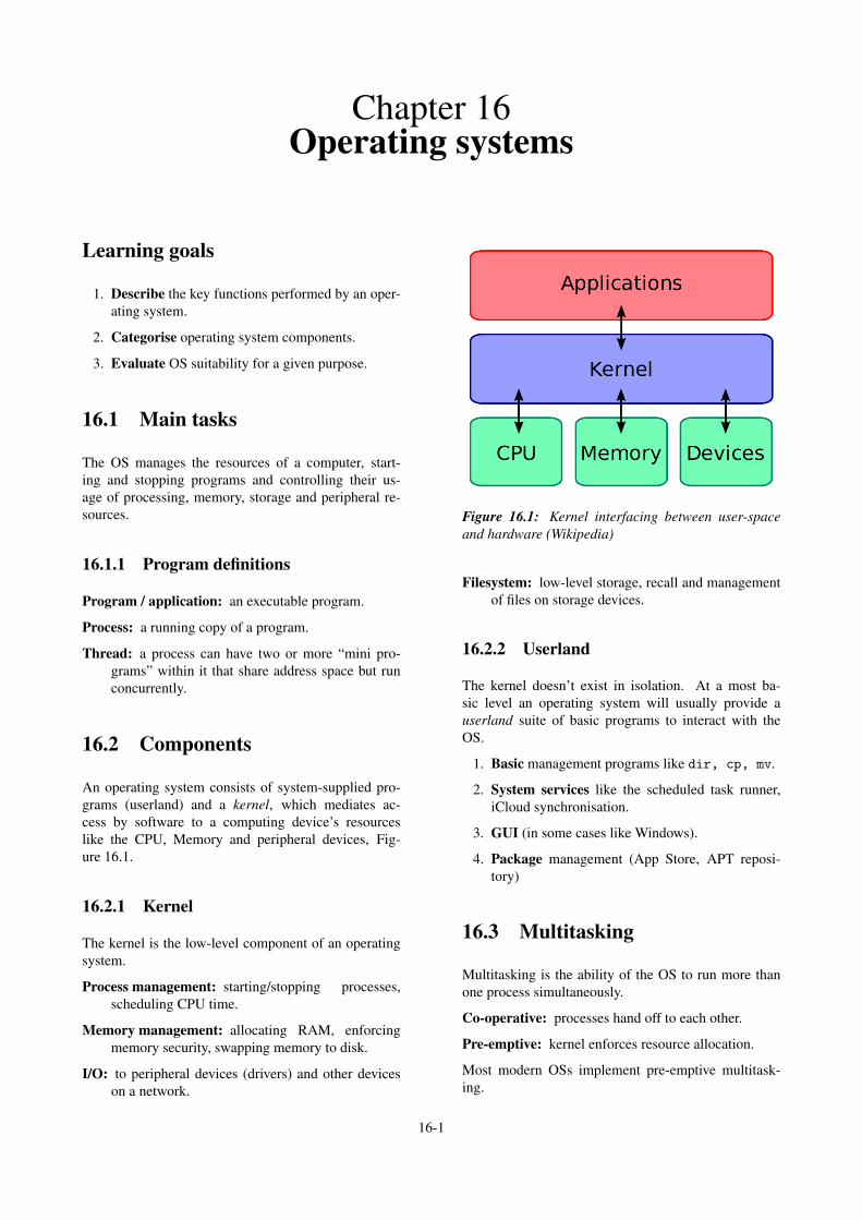
An operating system consists of system-supplied pro-grams (userland) and a kernel, which mediates ac-cess by software to a computing device’s resourceslike the CPU, Memory and peripheral devices, Fig-ure 16.1.
16.2.1 Kernel
The kernel is the low-level component of an operatingsystem.
Process management: starting/stopping processes,scheduling CPU time.
Memory management: allocating RAM, enforcingmemory security, swapping memory to disk.
I/O: to peripheral devices (drivers) and other deviceson a network.
Figure 16.1: Kernel interfacing between user-spaceand hardware (Wikipedia)
Filesystem: low-level storage, recall and managementof files on storage devices.
16.2.2 Userland
The kernel doesn’t exist in isolation. At a most ba-sic level an operating system will usually provide auserland suite of basic programs to interact with theOS.
1. Basic management programs like dir, cp, mv.
2. System services like the scheduled task runner,iCloud synchronisation.
3. GUI (in some cases like Windows).
4. Package management (App Store, APT reposi-tory)
16.3 Multitasking
Multitasking is the ability of the OS to run more thanone process simultaneously.
Co-operative: processes hand off to each other.
Pre-emptive: kernel enforces resource allocation.
Most modern OSs implement pre-emptive multitask-ing.
16-1

Chapter 17User interfaces
17-1

Chapter 18Scripting
18-1

Chapter 19Name resolution
19-1

Chapter 20DNS
1
CHAPTER 20. DNS 2
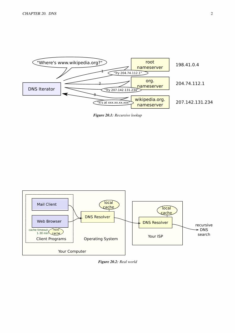
Figure 20.1: Recursive lookup
Your Computer
Client Programs Operating SystemYour ISP
cache timeout:
1-30 min
recursive
DNS
search
Figure 20.2: Real world

CHAPTER 20. DNS 3
Domain Name Space
= resource records
associated with name
see also: RFC 1034 4.2:
How the database is divided into zones.
= zone of authority,
managed by a name server
"delegated subzone"
"zone d
ele
gation"
NS RR ("resource record")
names the nameserver
authoritative for
delegated subzone
When a system administrator
wants to let another administrator
manage a part of a zone, the first
administrator's nameserver delegates
part of the zone to another
nameserver.
Figure 20.3: Domain Name Space