digital simulation of multimachine power systems for
TRANSCRIPT

IEEE TRANSACTIONS ON POWER APPARATUS AND SYSTEMS VOL. PAS-87} NO. 1 JANUARY 1968
existence will have to affect other groups and raise secondaryquestions which must be solved. A third and vital intangibleasset is the wake of trained people that such a project produces.
3) The digital computer has been in operation over a year andall programs work in practice as planned.
4) Dispatcher-computer communication is practical andworking well. The dispatchers who are responsible for its properoperation have shown good acceptance and are daily exhibitingimagination in the communication with and use of the digitalcomputer.
5) The program has at no time produced a predispatch showingless dollar cost with a system constraint than the same systemcondition without the system constraint, indicating the effective-ness of the program in optimizing dollar dispatch cost.
6) The pumped hydro and stored hydro water balance algo-rithm has always worked as planned.
7) The various techniques described in the paper made itpossible to limit the predispatch running time to well withinacceptable limits.
8) The off-line predispatch study is used for operation planningand, in addition, it can also be used for studies not strictly per-taining to day by day dispatch, such as providing the necessarydaily dispatch studies of hydro generation to produce a hydrorule curve.
9) Predispatch running time is generally between 2 and 30minutes depending on the mode and on the stored hydro andpumped hydro storage constraints.
SUMMARYConsiderable effort by both manufacturer and Union Electric
personnel has led to the realization of the goal of a practicaloptimum predispatch program and on-line control system, in-cluding the classical elements of conventional hydro and steamdispatch with the added dimensions of pumped hydro storageand economy interchange dispatch.
Innovations, such as the development of the prorate cycle costmethod of unit commitment, inclusion of optimum economyinterchange evaluation and pricing as an integral part of systemdispatch, and the development of a sophisticated water closurelogic scheme led to an overall system which is valid and practicalfrom the standpoints of operability, memory requirements, andprogram running time.
REFERENCES[1 T. Kennedy and E. M. Mabuce, "Dispatch of pumped hydro stor-
age on an interconnected hydrothermal system," IEEE Trans.Power A pparatus and Systems, vol. PAS-84, pp. 446-457, June 1965.
[2] "System dispatch with a digital-analog computer," pre-sented at the Missouri Valley Electric Association Meeting, KansasCity, Mo., April 9, 1965.
Digital Simulation of Multimachine Power Systems
for Stability StudiesK. PRABHASHANKAR AND WASYL JANISCHEWSYJ, ME-MBER, IEEE
Abstract-A digital simulation technique suitable for detailedanalysis of both large and small disturbances on extensive powersystems is presented. The analysis employs a hybrid reference framefor statement of the problem and for its solution. The equations ofthe interconnecting network are expressed with regard to a syn-chronously rotating common reference frame and are treated withthe aid of matrix methods. Synchronous machine equations andequations of the voltage regulator and of the speed governor aresolved in Park's reference frame fixed to the field of each individualmachine. Provision is made for representing different machines indifferent degrees of detail. An efficient numerical technique forsolution of the resulting complex nonlinear equations describing thebehavior of the complete power system is introduced.
IN VIEW OF the increasing complexity of present-day powersystems, their design and operation requires a more detailed
analysis of possible performance modes than may be achievedby available computer programs. In overcoming this difficulty,
Paper 31 TP 67-49, recommended and approved by the PowerSystem Engineering Committee of the IEEE Power Group forpresentation at the IEEE Winter Power Meeting, New York,N. Y., January 29-February 3, 1967. Manuscript submitted October31, 1966; made available for printing June 14, 1967.K. Prabhashankar is with Karnataka Regional Engineering Col-
lege, Surathkal, India.W. Janischewskj is with the University of Toronto, Toronto, On-
tario, Canada.
the present paper describes a digital simulation technique par-ticularly applicable to stability studies of extensive systems.
Studies of power system stability to date have developed alongtwo distinct paths. One approach, largely used in digital computerprograms,R[], [2] is based on the well-established network-analyzersimulation. This approach is well suited for handling large powersystems; however, its effectiveness is reduced by the inherentoversimplification in the representation of synchronous machines.The inadequacy is only partially offset by special techniquesthat approximately account for damping and braking torques.The second approach, widely used on analog computers,3_1-[6] ismore closely based on Park's equationsM71 and provides a moredetailed representation of synchronous machines. Unfortunately,an analog computer is unable to handle any practical-size powersystem. A different approach is proposed by the present paperwhich combines the strong points of both approaches and, inconsequence, is particularly suited for detailed stability analysisof large power systems.
DEVELOPMENT OF EQUATIONS FORMULTIMACHINE SYSTEM
Equations describing the behavior of the entire system aredeveloped on the basis of a hybrid reference frame. Each in-dividual synchronous machine is described by Park's equationsin a reference frame fixed to its own field and rotating with it.The complete set of equations includes governor and excitationsystems. Provision is made to represent by simpler models, if
73
Authorized licensed use limited to: NATIONAL INSTITUTE OF TECHNOLOGY SURATHKAL. Downloaded on May 08,2021 at 16:11:22 UTC from IEEE Xplore. Restrictions apply.
IEEE TRANSACTIONS ON POWER APPARATUS AND SYSTEMS JANUARY 1968
desired, machines electrically remote from a disturbance.The interconnecting network is stated in terms of a mixed
network matrix composed of impedances, admittances, anddimensionless elements. The associated solution for currents andvoltages at each specified node is expressed with regard to thesynchronously rotating common reference frame.Machines are connected to the network at the specified nodes,
at which voltages and currents in the two reference frames arerelated to one another by axis transformation. During any dis-turbance, speeds of machines change and hence their individualreference frames oscillate with respect to the synchronouslyrotating common reference frame.
In order to distinguish between reference frames, subscriptsd and q are used to denote components along the two axes ofmachine reference frames while subscripts D and Q refer tocomponents of the common reference frame.
Description of Synchronous MachineComplete description of the dynamic behavior of the syn-
chronous machine requires consideration of its electrical andmechanical characteristics as well as those of associated controlsystems. The necessary mathematical statements are sum-marized in the following paragraphs. Only those modes ofoperation that do not require zero-axis variables are considered.
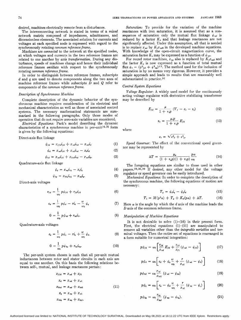
Electrical Equations: Park's model describing the dynamiccharacteristics of a synchronous machine in per-unit[41 [8] formis given by the following equations:
Direct-axis flux linkage
V'fd = Xffdfd + Xadikd -XXdd (1)
d= X adifd + X adikd - Xdid (2)
4kd = Xadifd + Xkkdikd - Xadid.
Quadrature-axis flux linkage
4 = X,itq - xqiq
/Iq = Xk4ik- Xaqi.
Direct-axis voltages
Vfd = - P4fd + rfdifd
ed = - p -d rid - X
0 = - Pkcd + rkdid.CtOO
Quadrature-axis voltages
=Q=- p40-ri9 + -CV.
1o = p4'k, + rk4,
coo
Saturation: To provide for the variation of the machinereactances with iron saturation, it is assumed that as a con-sequence of saturation only the mutual flux linkage ltad iSreduced by a factor K. and that leakage reactances are notsignificantly affected. Under this assumption, all that is neededis to replace Xad by K,xado in the developed machine equations.With knowledge of the open-circuit magnetization curve, thesaturation factor K, may be expressed as a function of Vad.For round rotor machines, Xaq also is replaced by K,x,aO and
the factor K, is now expressed as a function of total mutualflux 't, = (2tad + 42ta)"/2. The method used for the inclusion ofsaturation is by no means very rigorous. However, it provides asimple approach and leads to results that are reasonably wellsubstantiated in practice.[4]
Control System EquationsVoltage Regulator: A widely used model for the continuously
acting voltage regulator with derivative stabilizing transformermay be described by
Efd =A
(V.-eet - V)1 + rep E
V,= /2o Ef+ To,p
(12)
(13)
where
et e2d + e20.
Speed Governor: The effect of the convenitional speed gover-nor may be represented by
AT = Ag pa.(1 + rgp) (l + Thp) COO(3) (14)
The foregoing equations are similar to those used in other(4) papers.3[3],X1[5]9 If desired, any other model for the voltage5 regulator or speed governor can be easily introduced.(5) Mechanical Equations: In order to complete the description of
the synchronous machine, the following equations of motion arenecessary:
(6) T,J= V'diq - V'idTi = M1(p2a) + T0 + Kd(pa) + AT.
(15)
(16)
(7) Here a is the angle by which the d axis of the machine leads theD axis of the common reference frame.
(8) Manipulation of Machine EquationsIt is not desirable to solve (1)-(16) in their present form.
First, the electrical equations (1)-(11) are manipulated toremove all variables other than the integrable variables and ter-
(9) minal voltages. Then the entire set of equations is rearranged ina form suitable for numerical integration:
(10)
The per-unit system chosen is such that all per-unit mutualinductances between rotor and stator circuits in each axis areequal to one another. On this basis the following relations be-tween self-, mutual, and leakage reactances pertain:
Xffd = X ad + X11
Xd = Xad + Xal
Xkkd = X ad + Xkdl
Xq = Xaq + X al
Xkkg = Xaq + Xkql.
(11)
p#fd = Efd + (4d' 'fd)],d Xi
COePCOO .+a
d
P4kd = CO (4ad kcd)Xkdl
coo [eg {d Xal
p4',,0 = COO rk,,, (aq -k)Xk0l
(17)
(18)
(19)
(20)
(21)
74
Authorized licensed use limited to: NATIONAL INSTITUTE OF TECHNOLOGY SURATHKAL. Downloaded on May 08,2021 at 16:11:22 UTC from IEEE Xplore. Restrictions apply.
PRABHASHANKAR AND JANISCHEWSYJ: SIMULATION OF MULTIMACHINE POWER SYSTEMS
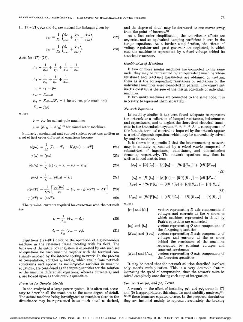
In (17)-(21), Pad and Pag are mutual flux linkages given by1 (Pd ALfd Aikd
Pad=T_7I -2+KA Xal Xf 1 Xkdl / (22)
aq1 (P1,0+ Pq (23)
Pe=K2 \Xai Xkql)(3Also, for (17)-(23),
K, 1 1 1 + 1Xad Xf 1 X a] Xkdl
1 1 1K2 =-+ +
Xag Xal Xk41
X = £ o+Pa
Xad = Kx adO
Xaq= Ksxa,o(K, = 1 for salient-pole machines)K, = f(p)
where
P = Pad for salient-pole machines
P = (P2ad + P2.q)112 for round rotor machines.
Similarly, mechanical and control system equations written asa set of first order differential equations become
v(pa) =I
[T - T- Kd(pa) - AT] (24)
p(a) = (pa) (25)
p(Efd) = -[M(Vr- et- v,) - Efd] (26)Xe
p(v.) = - U/(pEfd) -V] (27)7-a
p(pAT) =-[ ([ pa) - (7g + rA)(pT) - AT] (28)rg'rh 6<0
p(AT) = (pAT). (29)The terminal currents required for connection with the network
are
id= - (Pad -/d) (30)
(al a (31)
Equations (17)-(31) describe the operation of a synchronousmachine in the reference frame rotating with its field. Thebehavior of the entire power system is expressed by one such setof equations for each machine together with the terminal con-
straints imposed by the interconnecting network. In the processof computation, voltages ed and e0, which result from networkconstraints and appear as nonintegrable variables in machineequations, are considered as the input quantities for the solutionof the machine differential equations, whereas currents id andiq are looked upon as their output quantities.
Provision for Simpler Models
In the analysis of a large power system, it is often not neces-
sary to describe all the machines to the same degree of detail.The actual machine being investigated or machines close to thedisturbance may be represented in as much detail as desired,
and the degree of detail may be decreased as one moves awayfrom the point of interest.[4]As a first order simplification, the amortisseur effects are
neglected and an equivalent damping coefficient is used in thetorque equations. As a further simplification, the effects ofvoltage regulator and speed governor are neglected, in whichcase the machine is represented by a fixed voltage behind itstransient reactance.
Combination of MachinesIf two or more similar machines are connected to the same
node, they may be represented by an equivalent machine whoseresistance and reactance parameters are obtained by treatingthem as if the corresponding resistances or reactances of theindividual machines were connected in parallel. The equivalentinertia constant is the sum of the inertia constants of individualmachines.
If two unlike machines are connected to the same node, it isnecessary to represent them separately.
Network EquationsIn stability studies it has been found adequate to represent
the network as a collection of lumped resistances, inductances,and capacitances, and to neglect the short-lived electrical transi-ents in the transmission system.[8],[5],[9],[10] As a consequence ofthis fact, the terminal constraints imposed by the network appearas a set of algebraic equationis which may be conveniently solvedby matrix methods.
It is shown in Appendix I that the interconnecting networkmay be suitably represented by a mixed matrix composed ofsubmatrices of impedance, admittance, and dimensionlesselements, respectively. The network equations may then bewritten in real matrix form:
[eD] = [R][iD] - [x][iQ] - [RG][EMD] + [xB][EmQ](32)
[eQ] = [R] [iQ] + [XI[iD]- [RG][EMQ] - [xB][EMD]
[IMD] = [RG] T [iD] - [xB]7T[iQ] + [G][EMDn] - [B]I[EMQ](33)
[IMQ] = [RG]T [iQ] + [xB]T [iD] + [B][EMD] + [G][EMQ]where
[eD] and [iDI vectors representing D axis components ofvoltages and currents at the n nodes towhich machines represented in detail byPark's equations are connected
[eQ] and [iQ] vectors representing Q axis components ofthe foregoing quantities
[EMD] and [IMD] vectors representing D axis components ofvoltages and currents at the m nodesbehind the reactances of the machinesrepresented by constant voltages andtransient reactances
[EMQ] and [IMQ] vectors representing Q axis components ofthe foregoing quantities.
It may be noted that the network solution described involvesonly matrix multiplication. This is a very desirable featureincreasing the speed of computation, since the network must besolved completely once during each step of integration.
Comments on pPd and pp0 TermsA remark on the effect of including PPd and pP, terms in (7)
and (9) is appropriate at this stage. In most stability analyses, [],15], [9] these terms are equated to zero. In the proposed simulationthey are included mainly to represent accurately the braking
75
Authorized licensed use limited to: NATIONAL INSTITUTE OF TECHNOLOGY SURATHKAL. Downloaded on May 08,2021 at 16:11:22 UTC from IEEE Xplore. Restrictions apply.

IEEE TRANSACTIONS ON POWER APPARATUS AND SYSTEMS JANUARY 1968
torques which exist in machines during a fault. The effectof these torques is considered very important[6] and has to beaccurately accounted for in any detailed analysis.
Incidentally, there is an added advantage to the necessity ofsolving network equations separately when pqd and piq/ termsare present. The solution in that case, as explained earlier,involves only matrix multiplication. If, however, p;4 and p4 areneglected, the resulting algebraic equations describing machineshave to be solved simultaneously with those of the network.[10],[11] In consequence, solution involving only matrix multiplicationwill not be feasible and it may then be necessary to resort tointerative or other more complicated numerical techniques.
Axis TransformationEquations (17)-(31) describe an individual machine with
respect to its own reference frame. In general the reference frameof each machine is different from that of any other machine aswell as from the common reference frame rotating at synchronousspeed. Consequently, it is necessary to perform axis transforma-tion at each connection node in order to relate the components ofvoltages and currents expressed in the d, q reference axes of eachmachine to the synchronously rotating reference axes D, Q of thenetwork.Phasor relations between the two reference frames are shown in
Fig. 1. On its basis the transformation of eD, eQ to ed, e, and ofid, iq to iD, iQ may be stated as
ed = eD Cosa + eQsin a
e= eQ cos a - eD sin a (34)
D= td cos a - iq sin a
iQ = id sin a + i4 cos a. (35)
For a synchronous machine represented by a fixed voltagebehind the transient reactance, no axes transformation is needed.It is necessary only to find the components of the fixed voltagealong the D, Q axes of the common reference frame correspondingto each position of the machine's rotor. The values of currentcomponents obtained from the network solution together withthese voltage components give the electrical torque output to beused in (16).
If it is desired to represent one or more nodes as infinite buses,they can be handled in the same way as explained in the previousparagraph, with the only difference that in this case the com-ponents of the voltage along D, Q axes remain fixed. Con-sequently, any multiplication involving infinite bus voltagecomponents need be performed only once and stored, therebysaving on computer time.
Initial ConditionsBefore the differential equations representing the machines
can be solved, it is necessary to find the initial values of pertinentvariables. Prior to a disturbance the power output, power factor,terminal voltage, and current are known for each machine. Also,under steady-state conditions, ikd, ikq, and all the derivativeterms are zero.The situation is represented in the phasor diagram of Fig. 2,
from which the load angle a results as
Fig. 1. Axis-transformation phasor diagram.
d- axis
Fig. 2. Phasor diagram for computation of initial load angle.
Once the load angle a is determined, other variables may becomputed from
ed = et sina
eq = et cosa
id = it sin (a+ d)
iq = iCos ( + 0)
XIq = -ed -rid
Q'd = e0 + ri, (37)
e + ri, + Xdidtfd =
Xad
Pkd = X ad (ifd - id)
u'kq = aqi
V/f = Xffdifd - X adid
TX = d%q -iqid
efd = ?fd rfd.
The value of reactances xad and Xaq entering (37) are the saturatedvalues and are actually given by
Xad = KsXadO
Xaq = K,xaqO (Ks = 1 for salient-pole machine).
a = arctan itx6 cos 0-it R sin 0( ea + t R cos 0 + it xq sin 0
angle between q axis and etpower factormachine terminal current.
In the absence of a prior knowledge of K. it may be assumed equal(36) to unity and (37) may be solved iteratively along with the equa-
tion relating K, to the mutual flux linkage.Initially the common reference frame may be chosen arbitrarily.
Once this is done, however, the values of (, the angle between theterminal voltage of each machine and the chosen Q axis, becomefixed. With knowledge of ,B and 6, the angle between the referenceframe of the individual machine and the common reference frame
where
acos 6it
76
Authorized licensed use limited to: NATIONAL INSTITUTE OF TECHNOLOGY SURATHKAL. Downloaded on May 08,2021 at 16:11:22 UTC from IEEE Xplore. Restrictions apply.

PRABHASHANKAR AND JANISCHEWSYJ: SIMULATION OF MULTIMACHINE POWER SYSTEMS
mav be computed from
06-a -. (38)
COMPUTATION PROCEDUREStability analysis involves the solution of the set of differential
equations (17)-(29) together with that of the algebraic equations(30)-(35).
Choice of Numerical Integration SchemeThe literature on numerical integration for solution of ordinary
differential equations contains many techniques. In order toestablish an efficient scheme of computation, Runge-Kutta andpredictor-corrector methods are used alternatively.Runge-Kutta-Gil Alethod (RKG): Among the family of Runge-
Kutta methods, the most widely used version is that due to Gill.This method is readily applicable to digital computers requiringa minimum number of storage registers and controlling growth ofround-off errors.[12] In common with any of the Runge-Kuttafamily of methods, it is self-starting and stable. As indicated bythe description of the RKG method in Appendix II, the solutionof a set of differential equations involves the evaluation of therate of change of variables four times during each step of inte-gration. The present case involves a set of differential equationswhich are to be solved simultaneously with a set of algebraicequations, and hence the latter have to be solved four timesduring each step.Hamming's Predictor-Corrector Method: The reason for the
choice of Hamming's method is the fact that in addition tobeing stable it is noniterative. The method is summarized inAppendix II and requires two evaluations of the rate of change ofeach variable per step. To find the solution at any instant,knowledge of four previous values of each variable is necessaryand hence, besides requiring more storage registers, it is not self-starting.
Integration Step Length: As the total computing time is largelydependent on the integration interval, maximum permissiblestep length is a very important factor in the choice of the inte-gration method. For accurate solution of the differential equationsunder consideration, tests revealed that, for both RKG andHamming's methods, the largest step length permitted is in theneighborhood of 0.001 second.
This observation is in contrast with the results presented byHumpage and Scott,[t33 where, working with a simplified model,it was found that predictor-corrector methods permitted largerstep lengths than the RKG method. This observation is ap-parently the result of the fact that, when using the RKG method,Humpage and Scott solved algebraic equations only once at theend of each integration interval, whereby simultaneous solutionof differential and algebraic equations was not achieved. Shouldsimultaneous solution be performed, the permissible step lengthin the RKG method would be much larger, leading to an overallreduction of computation time in spite of the requirement that thenetwork be solved a larger number of times during each interval.
Auxiliary Prediction of Nonintegrable VariablesIt was mentioned earlier that Hamming's method requires
the solution of algebraic equations twice during each integrationinterval, one of them being (53) of this paper. An alternative tothe solution of the network at this point is the possibility ofextrapolating the nonintegrable variables ed and e,. A suitableformula for extrapolation using four previous values is given by(39), which is derived on the basis of Lagrange's equations inAppendix III.
eK+l =-eK-3 + 4eK-2- 6eK-1, + 4eK. (39)
Equation (39) was tested by comparing the resulting values ofed and e, with those obtained by the solution of the network.The agreement between the two sets was found to be very good.
Final Form of Integration SchemeAs a result of the auxiliary prediction of ed and e9, Hamming's
method requires the network solution, for each integration step,only once in addition to two evaluations of the rate of change ofintegrable variables. With this scheme, total computing timerequired is about half that required by the RKG method.Therefore, it was decided to adopt Hamming's method through-out the computation except for starting, which is achieved by theRKG method. When there is an abrupt change in the functionbeing integrated, for example, after a switching operation, theintegration is restarted by the RKG method.With a step length equal to 0.001 second, a 3-machine system
with all the machines represented in complete detail requires,for a study time duration of 3 seconds, 1.3 minutes of computingtime on an IBM 7094-II computer.
CONCLUSIONThe digital simulation technique described in the paper is
suitable for detailed stability analysis of a power system to anydisturbance either large or small. The synchronous generatormodel used provides for an accurate account of effects related toslip and to various damping and braking torques. These areimportant factors to be considered in any detailed analysis.The approach presented here can be extended to include othersituations such as unbalanced faults and dynamic loads.
APPENDIX IMATRIx REPRESENTATION OF NETWORK
The network admittance matrix Y may be written in par-titioned form as
y = YiJ y12]Y21 y2(40)
In the partioned matrix, the subscript 1 is associated with nodesto which controlled sources are connected and subscript 2 refersto those not connected to controlled sources. For the analysis noinformation about nodes associated with subscript 2 is neces-sary, and for this reason they are eliminated by a series ofsingle row and column reductions in accordance with
YR = I/l - Yl2Y2-lY21. (41)
The resultant network equations in terms of the reduced admit-tance matrix are
I = YRE.
These may be written in expanded form as
FIM YNN YMM1 EN
LIMYLYMNYmmJL EMj(42)
where the subscripts denote
N nodes connected to synchronous machines represented indetail by Park's equations
M nodes behind transient reactances of machines representedby fixed voltages.
In the analysis proposed, complete solution of the network isrequired once for each step of integration. Currents at the nodesassociated with the subscript N are known after the solution ofmachine differential equations; voltages EM, being fixed inmagnitude, are also known. Therefore, the purpose of the net-work solution is to find voltages EN and currents IM for use inthe next step of integration. For this purpose (42) is rearrangedinto
[I] YNZNN -ZNNYNM lFkiJ (43)['Mi = [NZNNYMM- YMNIZNNYNMJ LEmJ
77
Authorized licensed use limited to: NATIONAL INSTITUTE OF TECHNOLOGY SURATHKAL. Downloaded on May 08,2021 at 16:11:22 UTC from IEEE Xplore. Restrictions apply.
IEEE TRANSACTIONS ON POWER APPARATUS AND SYSTEMS JANUARY 1968
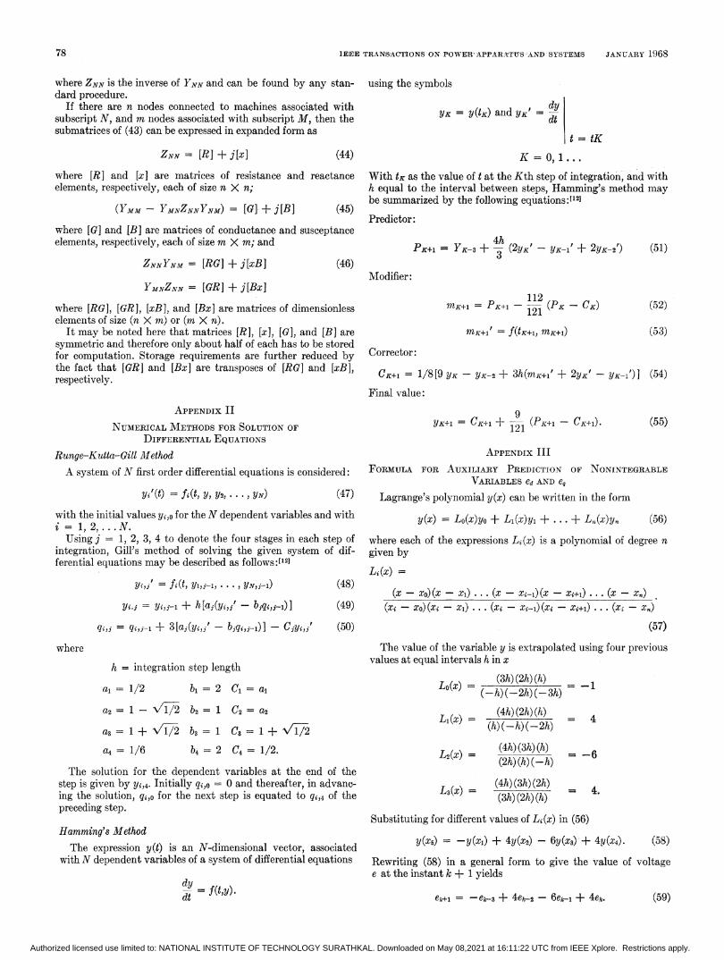
where ZNN is the inverse of YNN and can be found by any stan-dard procedure.
If there are n nodes connected to machines associated withsubscript N, and m nodes associated with subscript M, then thesubmatrices of (43) can be expressed in expanded form as
ZNN = [RI+ j[x] (44)where [R] and [x I are matrices of resistance and reactanceelements, respectively, each of size n X n;
(YMM - YMNZNNYNM) = [G] + j[B] (45)where [G] and [B] are matrices of conductance and susceptanceelements, respectively, each of size m X m; and
ZNNYNM = [RG] + j[xB] (46)
YMNZNN = [GR] + j[Bx]
where [RG], [GR], [xB], and [Bx] are matrices of dimensionlesselements of size (n X m) or (m X n).
It may be noted here that matrices [R], [xl, [G], and [B] aresymmetric and therefore only about half of each has to be storedfor computation. Storage requirements are further reduced bythe fact that [GR] and [Bx] are transposes of [RG] and [xB],respectively.
using the symbols
YK = Y(tK) and YK' =dt = tK
K = 0,1...
With tK as the value of t at the Kth step of integration, and withh equal to the interval between steps, Hamming's method maybe summarized by the following equations:[12]
Predictor:
PK+l = YK-3 + - (2YK' - YK-1' + 2YK-2')3(51)
Modifier:
MK+~K+ 12(PK - CK)121
MK+l ~=f(tK±l, mK+l)
(52)
(53)Corrector:
CK+1 = 1/8[9 YK - YK-2 + 3h(mK+1 + 2YK' - YK-i1) ] (54)
Final value:APPENDIX II
NUMERICAL METHODS FOR SOLUTION OFDIFFERENTIAL EQUATIONS
Runge-Kutta-Gill MlethodA system of N first order differential equations is considered:
(47)with the initial values yi,o for the N dependent variables and withi = 1, 2, ... N.
Using j = 1, 2, 3, 4 to denote the four stages in each step ofintegration, Gill's method of solving the given system of dif-ferential equations may be described as follows:[12]
YK+l = CK+1 + 2 (PK+l - CK+1).121 (55)
APPENDIX IIIFORMULA FOR AUXILIARY PREDICTION OF NONINTEGRABLE
VARIABLES ed AND eq
Lagrange's polynomial y(x) can be written in the form
y(x) = Lo(x)yo + L1(x)y, + . . . + L,,(x)y. (56)
where each of the expressions Li (x) is a polynomial of degree ngiven by
Li(x) =Yi,j = fi(t, Yl,j-l, . .. , YN,j-l)
yi,j = yi,j-1 + h[aj(yi,j' -biqi)-)]
qi,j = qi,j-i + 3 [aj(yi,j' - bjqi, -1)] -Cjyi,j'
(48) (x - xo) (x - x1) . . . (x - xi-1) (x - xi+1) . . . (x - Xe)(49) (xi - xo) (xi - xi) . . . (xi - xi-,) (xi - xi+i) .. . (x - x,)
(50)
where
h = integration step length
a, = 1/2 bi = 2 Ci= a,
(57)
The value of the variable y is extrapolated using four previousvalues at equal intervals h in x
Lo(x) (h) (2h) (h) -1
a2 = 1-V/1/2 b2 = 1 C2= a2
a3 =1+V//2 b3=1 C3=1+V12
a4 = 1/6 4 = 2 C4 = 1/2.
The solution for the dependent variables at the end of thestep is given by Yi,4. Initially qi,o = 0 and thereafter, in advanc-ing the solution, qi,o for the next step is equated to qi,4 of thepreceding step.
Hamming's MethodThe expression y(t) is an N-dimensional vector, associated
with N dependent variables of a system of differential equations
dy = f(t,y).
Li(x) =(4h) (2h) (h)
(h) (-h) (-2h)
L2(X) - (4h) (3h) (h)(2h) (h) (-h)
4
= -6
L3(x) =(4h) (3h) (2h) 4(3h) (2h) (h) =
Substituting for different values of Li(x) in (56)
y(x5) = -y(xi) + 4y(x2) - 6y(x3) -+ 4y(x4). (58)
Rewriting (58) in a general form to give the value of voltagee at the instant k + 1 yields
eA+l = -ek--3 + 4ek-2 - 6ek-1 + 4ek. (59)
78
Yi'(t) = fi (t, Y, Y2, - - - , YN)
Authorized licensed use limited to: NATIONAL INSTITUTE OF TECHNOLOGY SURATHKAL. Downloaded on May 08,2021 at 16:11:22 UTC from IEEE Xplore. Restrictions apply.
PRABHASHANKAR AND JANISCHEWSYJ: SIMULATION OF MULTIMACHINE POWER SYSTEMS
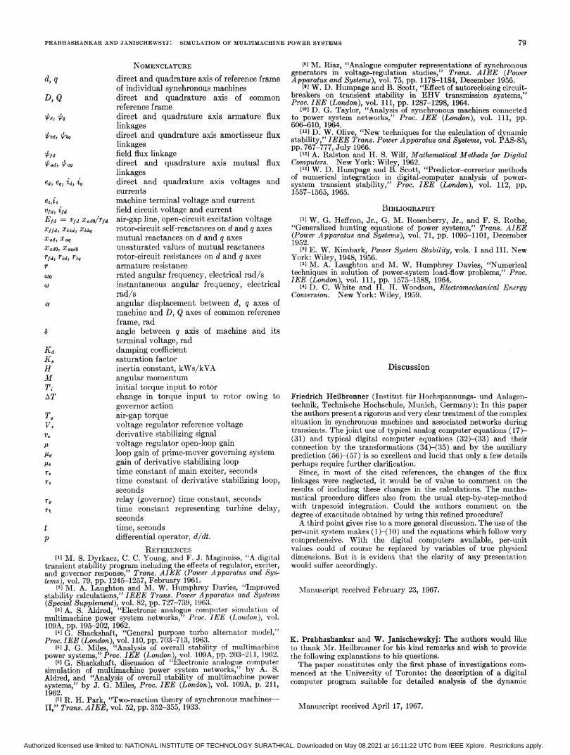
NOMENCLATUREdirect and quadrature axis of reference frameof individual synchronous machinesdirect and quadrature axis of commonreference framedirect and quadrature axis armature fluxlinkagesdirect and quadrature axis amortisseur fluxlinkagesfield flux linkagedirect and quadrature axis mutual fluxlinkagesdirect and quadrature axis voltages andcurrentsmachine terminal voltage and currentfield circuit voltage and currentair-gap line, open-circuit excitation voltagerotor-circuit self-reactances on d and q axesmutual reactances on d and q axesunsaturated values of mutual reactancesrotor-circuit resistances on d and q axesarmature resistancerated angular frequency, electrical rad/sinstantaneous angular frequency, electricalrad/sangular displacement between d, q axes ofmachine and D, Q axes of common referenceframe, radangle between q axis of machine and itsterminal voltage, raddamping coefficientsaturation factorinertia constant, kWs/kVAangular momentuminitial torque input to rotorchange in torque input to rotor owing togovernor actionair-gap torquevoltage regulator reference voltagederivative stabilizing signalvoltage regulator open-loop gainloop gain of prime-mover governing systemgain of derivative stabilizing looptime constant of main exciter, secondstime constant of derivative stabilizing loop,secondsrelay (governor) time constant, secondstime constant representing turbine delay,secondstime, secondsdifferential operator, d/dt.
REFERENCES['] M. S. Dyrkacz, C. C. Young, and F. J. Maginniss, "A digital
transient stability program including the effects of regulator, exciter,and governor response," Trans. AIEE (Power Apparatus and Sys-tems), vol. 79, pp. 1245-1257, February 1961.
[2] M. A. Laughton and M. W. Humphrey Davies, "Improvedstability calculations," IEEE Trans. Power A pparatus and Systems(Special Supplement), vol. 82, pp. 727-739, 1963.
[2] A. S. Aldred, "Electronic analogue computer simulation ofmultimachine power system networks," Proc. IEE (London), vol.109A, pp. 195-202, 1962.
[4] G. Shackshaft, "General purpose turbo alternator model,"Proc. IEE (London), vol. 110, pp. 703-713, 1963.
[1] J. G. Miles, "Analysis of overall stability of multimachinepower systems," Proc. IEE (London), vol. 109A, pp. 203-211, 1962.
[6] G. Shackshaft, discussion of "Electronic analogue computersimulation of multimachine power system networks," by A. S.Aldred, and "Analysis of overall stability of multimachine powersystems," by J. G. Miles, Proc. IEE (London), vol. 109A, p. 211,1962.
[7] R. H. Park, "Two-reaction theory of synchronous machines-II," Trans. AIEE, vol. 52, pp. 352-355, 1933.
[8] M. Riaz, "Analogue computer representations of synchroniousgenerators in voltage-regulation studies," Trans. AIEE (PowerApparatus and Systems), vol. 75, pp. 1178-1184, December 1956.
[9] W. D. Humpage and B. Scott, "Effect of autoreclosing circuit-breakers on transient stability in EHV transmission systems,"Proc. IEE (London), vol. 111, pp. 1287-1298, 1964.
110] D. G. Taylor, "Analysis of synchronous machines connectedto power system networks," Proc. IEE (London), vol. 111, pp.606-610, 1964.
[1l] D. W. Olive, "New techniques for the calculation of dynamicstability," IEEE Trans. Power Apparatus and Systems, vol. PAS-85,pp. 767-777, July 1966.
[12l A. Ralston and H. S. Wilf, Mathematical Methods for DigitalComputers. New York: Wiley, 1962.
[13] W. D. Humpage and B. Scott, "Predictor-corrector methodsof numerical integration in digital-computer analysis of power-system transient stability," Proc. IEE (London), vol. 112, pp.1557-1565, 1965.
BIBLIOGRAPHY[1] W. G. Heffron, Jr., G. M. Rosenberry, Jr., and F. S. Rothe,
"Generalized hunting equations of power systems," Trans. AIEE(Power Apparatus and Systems), vol. 71, pp. 1095-1101, December1952.
[2] E. W. Kimbark, Power System Stability, vols. I and III. NewYork: Wiley, 1948, 1956.
[3] M. A. Laughton and M. W. Humphrey Davies, "Numericaltechniques in solution of power-system load-flow problems," Proc.IEE (London), vol. 111, pp. 1575-1588, 1964.
[4] D. C. White and H. H. Woodson, Electromechanical EnergyConversion. New York: Wiley, 1959.
Discussion
Friedrich Heilbronner (Institut ffur Hochspannungs- und Anlagen-technik, Technische Hochschule, Munich, Germany): In this paperthe authors present a rigorous and very clear treatment of the complexsituation in synchronous machines and associated networks durinlgtransients. The joint use of typical analog computer equations (17)-(31) and typical digital computer equations (32)-(33) and theirconnection by the transformations (34)-(35) and by the auxiliaryprediction (56)-(57) is so excellent and lucid that only a few detailsperhaps require further clarification.
Since, in most of the cited references, the changes of the fluxlinkages were neglected, it would be of value to comment on theresults of including these changes in the calculations. The mathe-matical procedure differs also from the usual step-by-step-methodwith trapezoid integration. Could the authors comment on thedegree of exactitude obtained by using this refined procedure?A third point gives rise to a more general discussion. The use of the
per-unit system makes (1)-(10) and the equations which follow verycomprehensive. With the digital computers available, per-unitvalues could of course be replaced by variables of true physicaldimensions. But it is evident that the clarity of any presentationwould suffer accordingly.
MWanusscript received February 23, 1967.
K. Prabhashankar and W. Janischewskyj: The authors would liketo thank Mr. Heilbronner for his kind remarks and wish to providethe following explanations to his questions.The paper constitutes only the first phase of investigations com-
menced at the University of Toronto: the description of a digitalcomputer program suitable for detailed analysis of the dynamic
Manuscript received April 17, 1967.
d, q
D, Q
'Pd, 'Pg
kd7 ;4k
¢fd'Pad, 'Paq
ed, e0, id, tq
et,itVfd ifdEfd = Vfd XadO/rfd
Xffd Xked, XzkkqXadl XaqX adO) X a,dOrfd, rk, rmqrcoo
Cl!a
a
KdK.HmTiAT
TgVrvs
A8reMs
Tg
tp
79
Authorized licensed use limited to: NATIONAL INSTITUTE OF TECHNOLOGY SURATHKAL. Downloaded on May 08,2021 at 16:11:22 UTC from IEEE Xplore. Restrictions apply.

IEEE TRANSACTIONS ON POWER APPARATUS AND SYSTEMS VOL. PAS-87, NO. 1 JANUARY 1968
performance of power systems. The next step is the use of theprogram for study of computed stability performance resultingfrom omission of specific details in the system. Partial results ofthis study were given in the presentation; a separate paper is plannedfor future presentation.The changes in the flux linkages included in (18) and (20) represent
the electrical transients in the stator circuits. When these effects areconsidered, the air-gap torque includes high-frequency componentsas well as additional unidirectional terms. Of these, the effects ofunidirectional components are very important for machines veryclose to a short circuit. The braking effect of these torque com-ponents is often so large that the machine actually slows down for thefirst few cycles before accelerating. Inclusion of p4'd and p4iq terms, asdiscussed in the paper, offers an additional advantage, since thesolution of the network algebraic equations becomes noniterative.A disadvantage in this case, however, is that the maximum integra-tion step length for numerically stable solution is limited to about0.001 second rather than the 0.01 to 0.05 second permissible in thecase when the stator transients are neglected. This fact may morethan offset the advantage gained by the noniterative nature of the
network solution. We are at present considering the advantages tobe gained by the reduction of computer time when p#d and p4kqterms are neglected and the resulting additional algebraic equationsare solved by iterative techniques simultaneously with networkequations. In this case the fundamental frequency components ofid and i5, which correspond to the dc and second harmonic com-ponents of the phase currents, do not appear in the solution. Thestator and rotor resistance losses due to these components of currentsmay be computed to account for the initial braking torque.As regards the numerical method used, in view of the relatively
large number of differential equations involved, it was consideredappropriate to use higher order integration methods which are moreefficient than the simple step-by-step first-order method.The third point raised by Mr. Heilbronner may be discussed in
great detail; however, at this time it should suffice to state thatthe presented computer program could be easily modified to use allsystem variables in their true physical dimensions. On the otherhand, the employment of the per-unit system is justifiable on thebasis that system data are presently entered in the logs of powercompanies in per-unit values.
Formation of the Coefficient Matrix of a
Large Dynamic SystemJAMES E. VAN NESS, SENIOR MEMBER, IEEE, AND WILLIAM F. GODDARD
Abstract-The coefficient matrix for the set of first-order differ-ential equations that describe a dynamic system is formed from theblock diagram or equations that describe the system. The methodfor accomplishing this is described in terms of matrix equations.Then the derivative of this coefficient matrix with respect to one ofthe system parameters is found in terms of the matrices used toform it. The coefficient matrix and its derivative can be used to findthe eigenvalues of the system and the sensitivities of the eigenvaluesto the system's parameters.
INTRODUCTIONA WELL-KNOWN approach in conitrol systems analysis is to
represent the system by a set of first-order, linear differ-ential equations and to examine the eigenvalues of these equa-tions. If the equations describe the operation of the systemaround some equilibrium point, then the eigenvalues will charac-terize the dynamic response of the system. And, even though theequations are based upon a linear description of the system, theeigenvalues will give much information as to the response of thesystem to large disturbances where nonlinearities come intoeffect. Recently this approach has been successfully applied tothe study of large power systems.111-['] A difficulty is that the
Paper 31 TP 6748, recommended and approved by the PowerSystem Engineering Committee of the IEEE Power Group forpresentation at the IEEE Winter Power Meeting, New York, N. Y.,January 29-February 3, 1967. Manuscript submitted October 27,1966; made available for printing November 17, 1966. This workwas supported in part by the Bonneville Power Administration ofthe Department of the Interior under Contract 14-03-61278.
J. E. Van Ness is with Northwestern University, Evanston, Ill.W. F. Goddard is with the General Electric Company, Syracuse,
N. Y.
original description of the dynamic systems is generally in theform of block diagrams and not a set of differential equations.A method will be described here of forming a set of equations
of the form
Y = AY (1)
from the block diagram and other equations that describe asystem. In this equation, Y is a vector of the state variables forthe system. Y is its time derivative, and A is the coefficientmatrix. It is from the coefficient matrix that the eigenvalues canbe found. The method has been made very general so that manydifferent configurations can be studied. Thus, with this method,voltage regulators, devices to control the power flow on dctransmission lines, different types of governors, and other controlequipment can be easily added to the model, and their effect onsystems dynamics studied. Using this method a computerprogram can be written which will take parameters of a blockdiagram (gains, time constants, and signal flow) and supple-mentary equations as describing the system and form the Amatrix in the computer. Other programs which find the eigen-values and their sensitivities are presently available.
Since the sensitivities of the eigenvalues with respect to thesystem's parameters have proved to be very valuable in analyzinglarge systems,J][21 it is necessary to be able to form the deriva-tive of the matrix with respect to various system parameters.The method developed here gives a general formula for so doing.
DESCRIBING THE SYSTEM TO BE STUDIEDDynamic systems of the type to be studied by these methods
are most often described in terms of a block diagram with blocksof the type shown in Fig. 1. The method of forming the A matrixto be developed here will use these blocks as one of the majorforms of input data. In addition, equations such as the linearized
80
Authorized licensed use limited to: NATIONAL INSTITUTE OF TECHNOLOGY SURATHKAL. Downloaded on May 08,2021 at 16:11:22 UTC from IEEE Xplore. Restrictions apply.