digital servo drive for brushless or brush motors … · digital servo drive for brushless or brush...
TRANSCRIPT
RoHS
DIGITAL SERVO DRIVE for BRUSHLESS or BRUSH MOTORS
Harmonic Drive LLC, 247 Lynnfield Street, Peabody, MA 01960 Tel: 978.572.1800 Fax: 978.572.9406Web: www.harmonicdrive.net 800.921.3332 Page 1 of 32
RTL Series
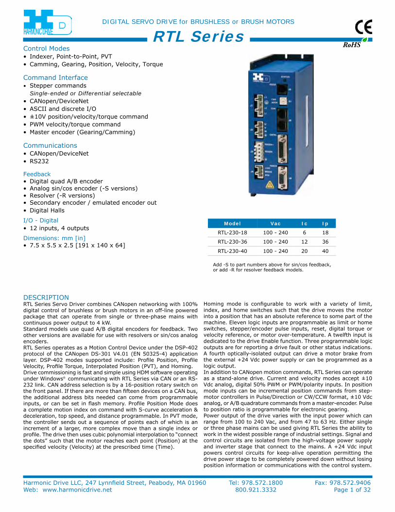
DeSCriPTionrTL Series Servo Driver combines CAnopen networking with 100% digital control of brushless or brush motors in an off-line powered package that can operate from single or three-phase mains with continuous power output to 4 kW.Standard models use quad A/B digital encoders for feedback. Two other versions are available for use with resolvers or sin/cos analog encoders.rTL Series operates as a Motion Control Device under the DSP-402 protocol of the CAnopen DS-301 V4.01 (en 50325-4) application layer. DSP-402 modes supported include: Profile Position, Profile Velocity, Profile Torque, interpolated Position (PVT), and Homing.Drive commissioning is fast and simple using HDM software operating under Windows® communicating with rTL Series via CAn or an rS-232 link. CAn address selection is by a 16-position rotary switch on the front panel. if there are more than fifteen devices on a CAn bus, the additional address bits needed can come from programmable inputs, or can be set in flash memory. Profile Position Mode does a complete motion index on command with S-curve acceleration & deceleration, top speed, and distance programmable. in PVT mode, the controller sends out a sequence of points each of which is an increment of a larger, more complex move than a single index or profile. The drive then uses cubic polynomial interpolation to “connect the dots” such that the motor reaches each point (Position) at the specified velocity (Velocity) at the prescribed time (Time).
Homing mode is configurable to work with a variety of limit, index, and home switches such that the drive moves the motor into a position that has an absolute reference to some part of the machine. eleven logic inputs are programmable as limit or home switches, stepper/encoder pulse inputs, reset, digital torque or velocity reference, or motor over-temperature. A twelfth input is dedicated to the drive enable function. Three programmable logic outputs are for reporting a drive fault or other status indications. A fourth optically-isolated output can drive a motor brake from the external +24 Vdc power supply or can be programmed as a logic output.in addition to CAnopen motion commands, rTL Series can operate as a stand-alone drive. Current and velocity modes accept ±10 Vdc analog, digital 50% PWM or PWM/polarity inputs. in position mode inputs can be incremental position commands from step-motor controllers in Pulse/Direction or CW/CCW format, ±10 Vdc analog, or A/B quadrature commands from a master-encoder. Pulse to position ratio is programmable for electronic gearing.Power output of the drive varies with the input power which can range from 100 to 240 Vac, and from 47 to 63 Hz. either single or three phase mains can be used giving rTL Series the ability to work in the widest possible range of industrial settings. Signal and control circuits are isolated from the high-voltage power supply and inverter stage that connect to the mains. A +24 Vdc input powers control circuits for keep-alive operation permitting the drive power stage to be completely powered down without losing position information or communications with the control system.
Control Modes • indexer, Point-to-Point, PVT • Camming, Gearing, Position, Velocity, Torque
Command interface• Stepper commands Single-ended or Differential selectable• CAnopen/Devicenet • ASCii and discrete i/o • ±10V position/velocity/torque command • PWM velocity/torque command • Master encoder (Gearing/Camming)
Communications• CAnopen/Devicenet • rS232
Feedback• Digital quad A/B encoder • Analog sin/cos encoder (-S versions) • resolver (-r versions) • Secondary encoder / emulated encoder out • Digital Halls
i/o - Digital• 12 inputs, 4 outputs
Dimensions: mm [in]• 7.5 x 5.5 x 2.5 [191 x 140 x 64]
Model Vac Ic Ip
rTL-230-18 100 - 240 6 18
rTL-230-36 100 - 240 12 36
rTL-230-40 100 - 240 20 40
Add -S to part numbers above for sin/cos feedback, or add -r for resolver feedback models.

RoHS
DIGITAL SERVO DRIVE for BRUSHLESS or BRUSH MOTORS
Harmonic Drive LLC, 247 Lynnfield Street, Peabody, MA 01960 Tel: 978.572.1800 Fax: 978.572.9406Web: www.harmonicdrive.net 800.921.3332 Page 2 of 32
RTL SeriesGenerAL SPeCiFiCATionS Test conditions: Wye connected load: 2 mH line-line. Ambient temperature = 25 °C. Power input = 230 Vac, 60 Hz, 1 Ø
MODEL rTL-230-18 rTL-230-36 rTL-230-40 Same specs for -S and -r modelsouTPuT CurrenT
Peak Current 18 (12.7) 36 (25.5) 40 (28.3) Adc (Arms, sinusoidal) Peak time 1 1 1 s Continuous current (note 1) 6 (4.24) 12 (8.5) 20 (14.1) Adc (Arms, sinusoidal)inPuT PoWer Mains voltage, phase, frequency 100~240 Vac, ±10%, 1 Ø or 3 Ø, 47~63 Hz Mains current 20 Arms +24 Vdc Control power +20 to +32 Vdc, 500 mA max required for operationDiGiTAL ConTroL Digital Control Loops Current, velocity, position. 100% digital loop control Sampling rate (time) Current loop: 15 kHz (67 µs), Velocity & position loops: 3 kHz (333 µs) Bus voltage compensation Changes in bus or mains voltage do not affect bandwidth Minimum load inductance 200 µH line-lineCoMMAnD inPuTS (noTe: DiGiTAL inPuT FunCTionS Are ProGrAMMABLe) Distributed Control Modes CAnopen Position, Velocity, Torque, Homing, Profile, and interpolated profile modes Devicenet® Compatible with Allen-Bradley PLC’s ASCii Multiple drives accessible from a single rS-232 port Stand-alone mode Analog torque, velocity, position reference ±10 Vdc, 12 bit resolution Dedicated differential analog input input impedance 74.8 kΩ Between ref(+), ref(-) Digital position reference Pulse/Direction, CW/CCW Stepper commands (2 MHz maximum rate) Quad A/B encoder 2 M line/sec, 8 Mcount/sec (after quadrature) Digital torque & velocity reference PWM , Polarity PWM = 0% - 100%, Polarity = 1/0 PWM 50% PWM = 50% ±50%, no polarity signal required PWM frequency range 1 kHz minimum, 100 kHz maximum PWM minimum pulse width 220 ns indexing up to 32 programs can be launched from inputs or ASCii commands. each program can consist of moves, i/o commands, time delays, and other programmable operations. Camming Master quadrature encoder provides position as index to cam table. Digital inputs initiate cam functions.DiGiTAL inPuTS number 12 inputs [in1~5,11,12] 74HC14 Schmitt trigger, 330 µs rC filter, Vin-Lo < 1.35 Vdc, Vin-Hi >3.65 Vdc, +24 Vdc max [in1] dedicated to drive enable function, other inputs are programmable input [in6] 74HC14 Schmitt trigger, 100 ns rC filter, Vin-Lo < 1.35 Vdc, Vin-Hi >3.65 Vdc, +12 Vdc max inputs [in7~10] Single-ended: Comparator with 2.5 Vdc reference, 100 ns rC filter, Vin-Lo <2.3 Vdc, Vin-Hi > 2.45 Vdc Differential: rS-485 line receiver on input pairs [in9-7], and [in10-8], 100 ns rC filters, +12 Vdc max All inputs 10 kΩ pull-up to +5 Vdc or pull-down to ground, selectable in groups, active level programmableDiGiTAL ouTPuTS (noTe 2) number 4 [ouT1], [ouT2], [ouT3] Current-sinking MoSFeT with 1 kΩ pullup to +5 Vdc through diode Current rating 1 Adc max, +40 Vdc max. Functions programmable external flyback diode required if driving inductive loads Brake [ouT4] opto-isolated, current-sinking with flyback diode to +24 Vdc, 1 Adc maxMuLTi-MoDe enCoDer PorT
As input Secondary digital quadrature encoder (A, /A, B, /B, X, /X), 121 Ω terminating resistors 18 M-counts/sec, post-quadrature (4.5 M-lines/sec) As output Quadrature encoder emulation with programmable resolution to 4096 lines (65,536 counts) per rev from analog sin/cos encoders or resolvers. Buffered signals from digital quad A/B/X primary encoder A, /A, B, /B, X, /X, from 26LS31 differential line driver
rS-232 PorT Signals rxD, TxD, Gnd in 6-position, 4-contact rJ-11 style modular connector Mode Full-duplex, DTe serial communication port for drive setup and control, 9,600 to 115,200 baud Protocol Binary and ASCii formatsCAn PorTS Signals CAnH, CAnL, Gnd in 8-position rJ-45 style modular connector, wired as per CAn Cia Dr-303-1, V1.1 Format CAn V2.0b physical layer for high-speed connections compliant Data CAnopen Device Profile DSP-402 Address selection 16 position rotary switch on front panel with 3 additional address bits available as digital inputs or programmable to flash memory (7-bit addressing, 127 nodes per CAn network)STATuS inDiCATorS Drive Status Bicolor LeD, drive status indicated by color, and blinking or non-blinking condition CAn Status Bicolor LeD, status of CAn bus indicated by color and blink codes to CAn indicator Specification 303-3reGenerATion
operation internal solid-state switch drives external regen resistor (see ordering Guide for types) Cut-in Voltage +HV > 390 Vdc regen output is on, (optional external) regen resistor is dissipating energy Drop-out Voltage +HV < 380 Vdc regen output is off, (optional external) regen resistor not dissipating energy Tolerance ±2 Vdc For either Cut-in or Drop-out voltage
noTeS: 1. Heatsinking and/or forced-air cooling is required for continuous output power rating
2. Brake[ouT4] is programmable as motor brake, or as general purpose digital output
RoHS
DIGITAL SERVO DRIVE for BRUSHLESS or BRUSH MOTORS
Harmonic Drive LLC, 247 Lynnfield Street, Peabody, MA 01960 Tel: 978.572.1800 Fax: 978.572.9406Web: www.harmonicdrive.net 800.921.3332 Page 3 of 32
RTL Series
enCoDer
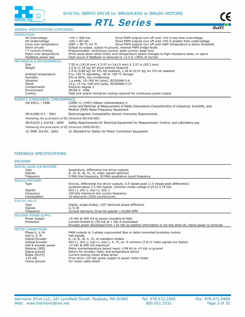
DiGiTAL QuAD A/B enCoDer Type Quadrature, differential line driver outputs Signals A, /A, B, /B, (X, /X, index signals optional) Frequency 5 MHz line frequency, 20 MHz quadrature count frequency
AnALoG enCoDer Type Sin/cos, differential line driver outputs, 0.5 Vpeak-peak (1.0 Vpeak-peak differential) centered about 2.5 Vdc typical. Common-mode voltage 0.25 to 3.75 Vdc Signals Sin(+), sin(-), cos(+), cos(-) Frequency 230 kHz maximum line (cycle) frequency interpolation 10 bits/cycle (1024 counts/cycle)
DIGITAL HALLS Type Digital, single-ended, 120° electrical phase difference Signals u, V, W Frequency Consult Harmonic Drive for speeds >10,000 rPM
enCoDer PoWer SuPPLy Power Supply +5 Vdc @ 400 mA to power encoders & Halls Protection Current-limited to 750 mA @ 1 Vdc if overloaded encoder power developed from +24 Vdc so position information is not lost when AC mains power is removed
MoTor ConneCTionS Phase u, V, W PWM outputs to 3-phase ungrounded Wye or delta connected brushless motors Hall u, V, W Hall signals Digital encoder A, /A, B, /B, X, /X, on standard models Analog encoder Sin(+), sin(-), cos(+), cos(-), X, /X, on -S versions (X & /X index signals are digital) Hall & encoder power +5 Vdc @ 400 mA maximum Motemp [in5] Motor overtemperature sensor input, 4.99 kΩ to +5 Vdc or ground Signal ground return for encoder, Halls, and temperature sensor Brake [ouT4] Current-sinking motor brake driver +24 Vdc From drive +24 Vdc power supply to power motor brake Frame ground For motor cable shield
FeeDBACk SPeCiFiCATionS
GenerAL SPeCiFiCATionS (ConTinueD)
ProTeCTionS HV overvoltage +HV > 400 Vdc Drive PWM outputs turn off until +HV is less than overvoltage HV undervoltage +HV < 60 Vdc Drive PWM outputs turn off until +HV is greater than undervoltage Drive over temperature iGBT > 80 °C ±3 °C Drive PWM outputs turn off until iGBT temperature is below threshold Short circuits output to output, output to ground, internal PWM bridge faults I2T Current limiting Programmable: continuous current, peak current, peak time Motor over temperature Drive shuts down when motor over-temperature switch changes to high-resistance state, or opens Feedback power loss Fault occurs if feedback is removed or +5 V is <85% of normal
MeCHAniCAL & enVironMenTAL Size 7.55 in (191,8 mm) X 5.57 in (141,5 mm) X 2.57 in (65,3 mm) Weight 3.0 lb (1.36 kg) for drive without heatsink 1.9 lb (0.86 kg) for XTL-HS heatsink, 1.26 lb (0.57 kg) for XTL-HL heatsink Ambient temperature 0 to +45 °C operating, -40 to +85 °C storage Humidity 0% to 95%, non-condensing Vibration 2 g peak, 10~500 Hz (sine), ieC60068-2-6 Shock 10 g, 10 ms, half-sine pulse, ieC60068-2-27 Contaminants Pollution degree 2 environment ieC68-2: 1990 Cooling Heat sink and/or forced air cooling required for continuous power output
AGenCy STAnDArDS ConForMAnCeen 55011 : 1998 CiSPr 11 (1997) edition 2/Amendment 2:
Limits and Methods of Measurement of radio Disturbance Characteristics of industrial, Scientific, and Medical (iSM) radio Frequency equipment
en 61000-6-1 : 2001 electromagnetic Compatibility Generic immunity requirementsFollowing the provisions of EC Directive 89/336/EEC:en 61010-1 2nd ed.: 2004 Safety requirements for electrical equipment for Measurement, Control, and Laboratory useFollowing the provisions of EC Directive 2006/95/EC:uL 508C 3rd ed.: 2002 uL Standard for Safety for Power Conversion equipment
RoHS
DIGITAL SERVO DRIVE for BRUSHLESS or BRUSH MOTORS
Harmonic Drive LLC, 247 Lynnfield Street, Peabody, MA 01960 Tel: 978.572.1800 Fax: 978.572.9406Web: www.harmonicdrive.net 800.921.3332 Page 4 of 32
RTL Series
REG
EN+
REG
EN-
REG
EN+
REG
EN-
3.00 (76,2)
1.5 (38,1)
7.15 (181,6) 5.54 (140,7)
2.55 (64,8)
1.99 (50,5)
0.925 (23,5)
STANDARDHEATSINK OPTION (-HS)
6.75(171,5)
LOW-PROFILEHEATSINK OPTION (-HL)0.88 (22,4)
1.00 (25,4)
8 x 0.160
7.55 (191,7)
(4,1)
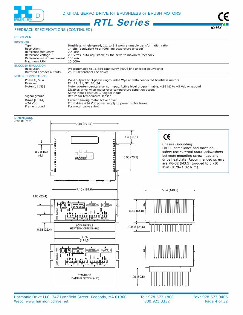
Chassis Grounding: For Ce compliance and machine safety use external tooth lockwashers between mounting screw head and drive heatplate. recommended screws are #6-32 (M3.5) torqued to 8~10 lb·in (0.79~1.02 n·m).
DiMenSionS inches (mm)
RESOLVER
RESOLVER Type Brushless, single-speed, 1:1 to 2:1 programmable transformation ratio resolution 14 bits (equivalent to a 4096 line quadrature encoder) reference frequency 7.5 kHz reference voltage 2.8 Vrms, auto-adjustable by the drive to maximize feedback reference maximum current 100 mA Maximum rPM 10,000+
enCoDer eMuLATion resolution Programmable to 16,384 counts/rev (4096 line encoder equivalent) Buffered encoder outputs 26C31 differential line driver
MoTor ConneCTionS Phase u, V, W PWM outputs to 3-phase ungrounded Wye or delta connected brushless motors resolver r1, r2, S1, S2, S3, S4 Motemp [in5] Motor overtemperature sensor input. Active level programmable. 4.99 kΩ to +5 Vdc or ground Disables drive when motor over-temperature condition occurs Same input circuit as GP digital inputs Signal ground return for temperature sensor Brake [ouT4] Current-sinking motor brake driver +24 Vdc From drive +24 Vdc power supply to power motor brake Frame ground For motor cable shield
FeeDBACk SPeCiFiCATionS (ConTinueD)
RoHS
DIGITAL SERVO DRIVE for BRUSHLESS or BRUSH MOTORS
Harmonic Drive LLC, 247 Lynnfield Street, Peabody, MA 01960 Tel: 978.572.1800 Fax: 978.572.9406Web: www.harmonicdrive.net 800.921.3332 Page 5 of 32
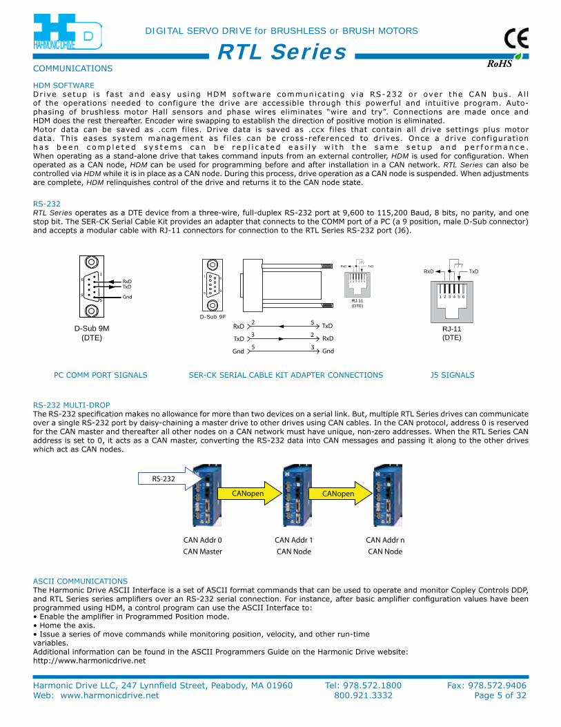
RTL SeriesHDM SoFTWAreDr ive setup is fast and easy us ing HDM software communicat ing v ia rS-232 or over the CAn bus. A l l of the operations needed to configure the drive are accessible through this powerful and intuitive program. Auto-phasing of brushless motor Hall sensors and phase wires eliminates “wire and try”. Connections are made once and HDM does the rest thereafter. encoder wire swapping to establish the direction of positive motion is eliminated.Motor data can be saved as .ccm files. Drive data is saved as .ccx files that contain all drive settings plus motor data. This eases system management as fi les can be cross-referenced to drives. once a drive configuration h a s b e e n c o m p l e t e d s y s t e m s c a n b e r e p l i c a t e d e a s i l y w i t h t h e s a m e s e t u p a n d p e r f o r m a n c e . When operating as a stand-alone drive that takes command inputs from an external controller, HDM is used for configuration. When operated as a CAn node, HDM can be used for programming before and after installation in a CAn network. RTL Series can also be controlled via HDM while it is in place as a CAn node. During this process, drive operation as a CAn node is suspended. When adjustments are complete, HDM relinquishes control of the drive and returns it to the CAn node state.
CoMMuniCATionS
6
9
1
5
RxDTxD
Gnd
D-Sub 9M(DTE)
6
9
1
5
D-Sub 9F
RxD TxD
1 2 3 4 5 6
RJ-11(DTE)
RxD3 2TxD2 5
Gnd
RxD
TxD
Gnd5 3
RxD TxD
1 2 3 4 5 6
RJ-11(DTE)
rS-232RTL Series operates as a DTe device from a three-wire, full-duplex rS-232 port at 9,600 to 115,200 Baud, 8 bits, no parity, and one stop bit. The Ser-Ck Serial Cable kit provides an adapter that connects to the CoMM port of a PC (a 9 position, male D-Sub connector) and accepts a modular cable with rJ-11 connectors for connection to the rTL Series rS-232 port (J6).
rS-232 MuLTi-DroPThe rS-232 specification makes no allowance for more than two devices on a serial link. But, multiple rTL Series drives can communicate over a single rS-232 port by daisy-chaining a master drive to other drives using CAn cables. in the CAn protocol, address 0 is reserved for the CAn master and thereafter all other nodes on a CAn network must have unique, non-zero addresses. When the rTL Series CAn address is set to 0, it acts as a CAn master, converting the rS-232 data into CAn messages and passing it along to the other drives which act as CAn nodes.
ASCii CoMMuniCATionSThe Harmonic Drive ASCii interface is a set of ASCii format commands that can be used to operate and monitor Copley Controls DDP, and rTL Series series amplifiers over an rS-232 serial connection. For instance, after basic amplifier configuration values have been programmed using HDM, a control program can use the ASCii interface to:• enable the amplifier in Programmed Position mode.• Home the axis.• issue a series of move commands while monitoring position, velocity, and other run-timevariables.Additional information can be found in the ASCii Programmers Guide on the Harmonic Drive website:http://www.harmonicdrive.net
Ser-Ck SeriAL CABLe kiT ADAPTer ConneCTionS J5 SiGnALSPC CoMM PorT SiGnALS
CANopen
RS-232
CANopen
CAN Addr 0CAN Master CAN Node CAN Node
CAN Addr 1 CAN Addr n
RoHS
DIGITAL SERVO DRIVE for BRUSHLESS or BRUSH MOTORS
Harmonic Drive LLC, 247 Lynnfield Street, Peabody, MA 01960 Tel: 978.572.1800 Fax: 978.572.9406Web: www.harmonicdrive.net 800.921.3332 Page 6 of 32
RTL Series
CAN Status LED
J6
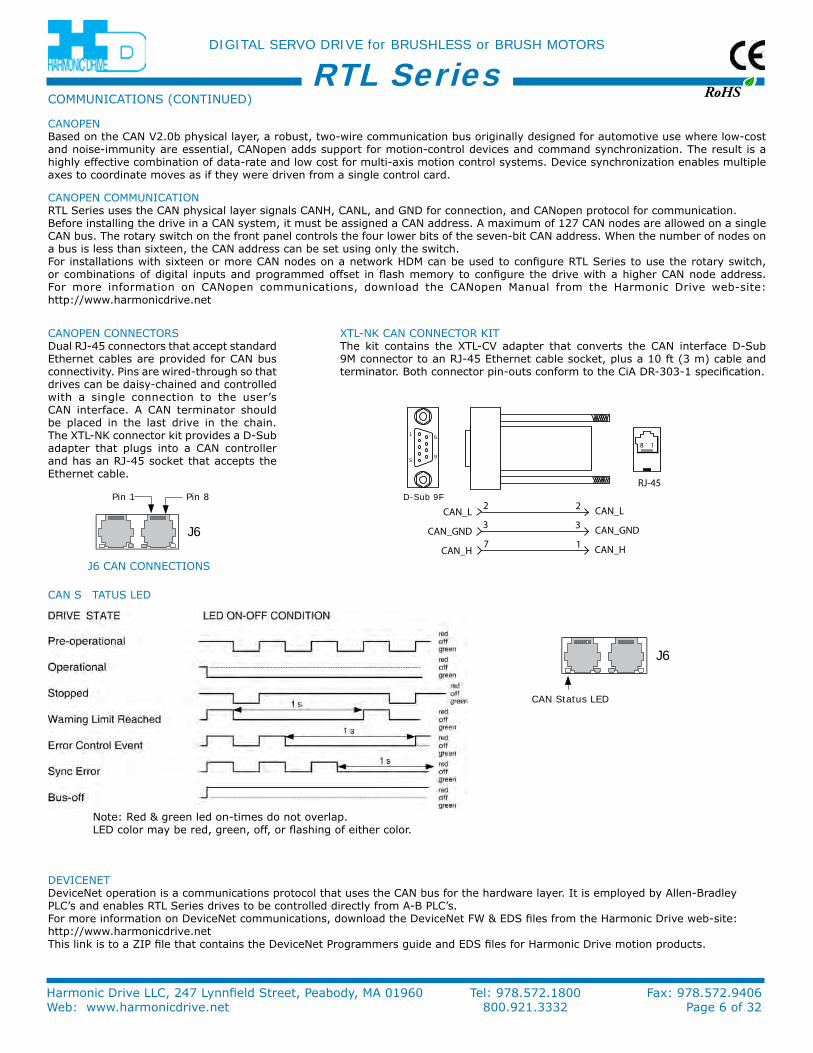
DeViCeneTDevicenet operation is a communications protocol that uses the CAn bus for the hardware layer. it is employed by Allen-Bradley PLC’s and enables rTL Series drives to be controlled directly from A-B PLC’s. For more information on Devicenet communications, download the Devicenet FW & eDS files from the Harmonic Drive web-site:http://www.harmonicdrive.net This link is to a ZiP file that contains the Devicenet Programmers guide and eDS files for Harmonic Drive motion products.
CAnoPen CoMMuniCATionrTL Series uses the CAn physical layer signals CAnH, CAnL, and GnD for connection, and CAnopen protocol for communication. Before installing the drive in a CAn system, it must be assigned a CAn address. A maximum of 127 CAn nodes are allowed on a single CAn bus. The rotary switch on the front panel controls the four lower bits of the seven-bit CAn address. When the number of nodes on a bus is less than sixteen, the CAn address can be set using only the switch.For installations with sixteen or more CAn nodes on a network HDM can be used to configure rTL Series to use the rotary switch, or combinations of digital inputs and programmed offset in flash memory to configure the drive with a higher CAn node address. For more information on CAnopen communications, download the CAnopen Manual from the Harmonic Drive web-site: http://www.harmonicdrive.net
CAnoPenBased on the CAn V2.0b physical layer, a robust, two-wire communication bus originally designed for automotive use where low-cost and noise-immunity are essential, CAnopen adds support for motion-control devices and command synchronization. The result is a highly effective combination of data-rate and low cost for multi-axis motion control systems. Device synchronization enables multiple axes to coordinate moves as if they were driven from a single control card.
note: red & green led on-times do not overlap. LeD color may be red, green, off, or flashing of either color.
CAn S TATuS LeD
CoMMuniCATionS (ConTinueD)
6
9
1
5
D-Sub 9F
3 3
2 2
18
CAN_L
CAN_GND
CAN_H
CAN_L
RJ-45
CAN_GND
CAN_H7 1J6
Pin 8Pin 1
CAnoPen ConneCTorSDual rJ-45 connectors that accept standard ethernet cables are provided for CAn bus connectivity. Pins are wired-through so that drives can be daisy-chained and controlled with a single connection to the user’s CAn interface. A CAn terminator should be placed in the last drive in the chain. The XTL-nk connector kit provides a D-Sub adapter that plugs into a CAn controller and has an rJ-45 socket that accepts the ethernet cable.
XTL-nk CAn ConneCTor kiTThe kit contains the XTL-CV adapter that converts the CAn interface D-Sub 9M connector to an rJ-45 ethernet cable socket, plus a 10 ft (3 m) cable and terminator. Both connector pin-outs conform to the CiA Dr-303-1 specification.
J6 CAn ConneCTionS
RoHS
DIGITAL SERVO DRIVE for BRUSHLESS or BRUSH MOTORS
Harmonic Drive LLC, 247 Lynnfield Street, Peabody, MA 01960 Tel: 978.572.1800 Fax: 978.572.9406Web: www.harmonicdrive.net 800.921.3332 Page 7 of 32
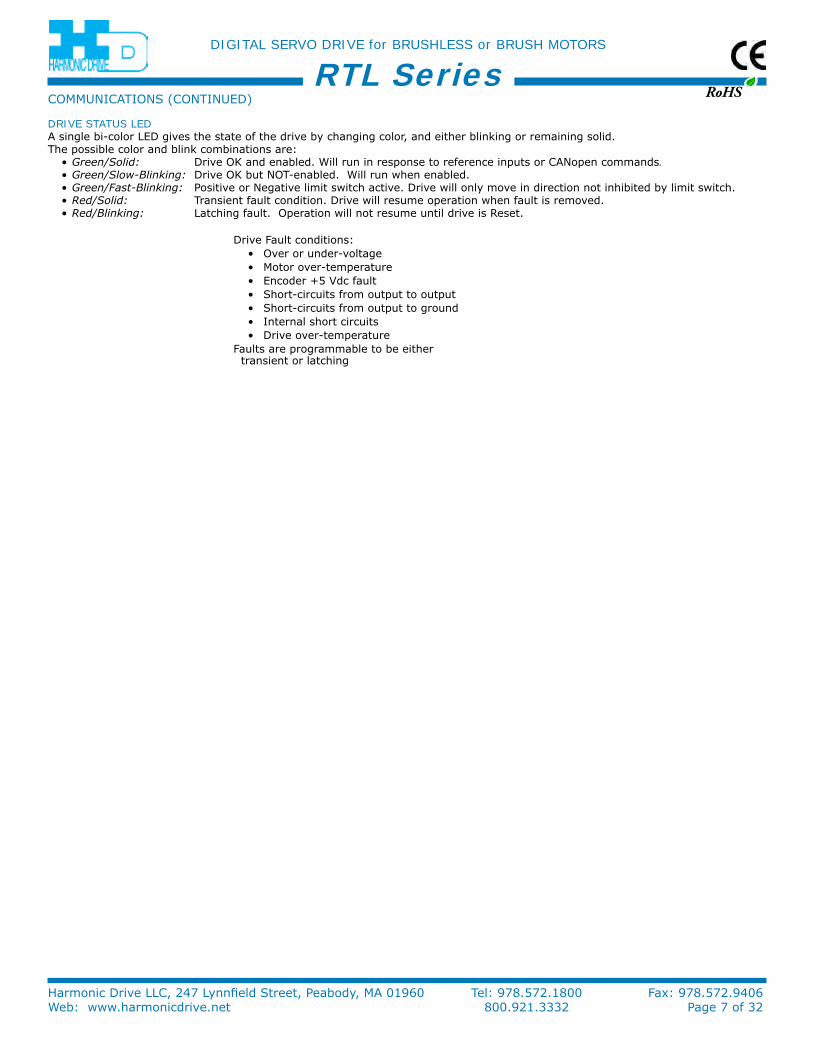
RTL SeriesDRIVE STATUS LEDA single bi-color LeD gives the state of the drive by changing color, and either blinking or remaining solid. The possible color and blink combinations are:•Green/Solid: Drive ok and enabled. Will run in response to reference inputs or CAnopen commands.•Green/Slow-Blinking: Drive ok but noT-enabled. Will run when enabled.•Green/Fast-Blinking: Positive or negative limit switch active. Drive will only move in direction not inhibited by limit switch.•Red/Solid: Transient fault condition. Drive will resume operation when fault is removed.•Red/Blinking: Latching fault. operation will not resume until drive is reset.
Drive Fault conditions:• over or under-voltage• Motor over-temperature• encoder +5 Vdc fault• Short-circuits from output to output• Short-circuits from output to ground• internal short circuits• Drive over-temperature
Faults are programmable to be either transient or latching
CoMMuniCATionS (ConTinueD)
RoHS
DIGITAL SERVO DRIVE for BRUSHLESS or BRUSH MOTORS
Harmonic Drive LLC, 247 Lynnfield Street, Peabody, MA 01960 Tel: 978.572.1800 Fax: 978.572.9406Web: www.harmonicdrive.net 800.921.3332 Page 8 of 32
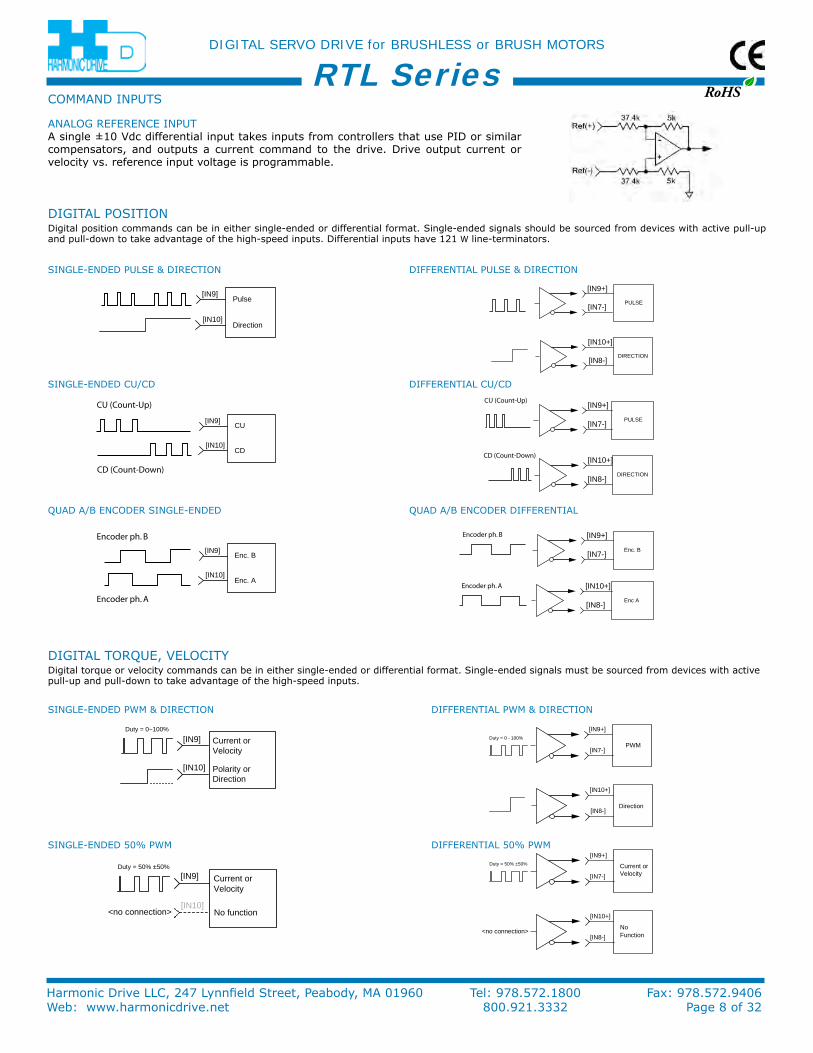
RTL SeriesAnALoG reFerenCe inPuTA single ±10 Vdc differential input takes inputs from controllers that use PiD or similar compensators, and outputs a current command to the drive. Drive output current or velocity vs. reference input voltage is programmable.
CoMMAnD inPuTS
PULSE
[IN9+]
[IN7-]
DIRECTION
[IN10+]
[IN8-]
PULSE
[IN9+]
[IN7-]
DIRECTION
[IN10+]
[IN8-]
CD (Count-Down)
CU (Count-Up)
Pulse
Direction
[IN9]
[IN10]
CU
CD
[IN9]
[IN10]
CU (Count-Up)
CD (Count-Down)
Enc. B
Enc. A
[IN9]
[IN10]
Encoder ph. A
Encoder ph. B
Enc A
[IN10+]
[IN8-]
Encoder ph. A
Enc. B
[IN9+]
[IN7-]
Encoder ph. B
DiGiTAL PoSiTionDigital position commands can be in either single-ended or differential format. Single-ended signals should be sourced from devices with active pull-up and pull-down to take advantage of the high-speed inputs. Differential inputs have 121 W line-terminators.
SinGLe-enDeD PuLSe & DireCTion
DiFFerenTiAL Cu/CD
DiFFerenTiAL PuLSe & DireCTion
SinGLe-enDeD Cu/CD
QuAD A/B enCoDer SinGLe-enDeD QuAD A/B enCoDer DiFFerenTiAL
DiGiTAL TorQue, VeLoCiTyDigital torque or velocity commands can be in either single-ended or differential format. Single-ended signals must be sourced from devices with active pull-up and pull-down to take advantage of the high-speed inputs.
Current orVelocity
Polarity orDirection
[IN9]
[IN10]
Duty = 0~100%
SinGLe-enDeD PWM & DireCTion
Current orVelocity
No function
[IN9]
[IN10]
Duty = 50% ±50%
<no connection>
SinGLe-enDeD 50% PWM
Current orVelocity
[IN9+]
[IN7-]
Duty = 50% ±50%
NoFunction
<no connection>
[IN10+]
[IN8-]
DiFFerenTiAL 50% PWM
PWM
[IN9+]
[IN7-]
Duty = 0 - 100%
Direction
[IN10+]
[IN8-]
DiFFerenTiAL PWM & DireCTion
RoHS
DIGITAL SERVO DRIVE for BRUSHLESS or BRUSH MOTORS
Harmonic Drive LLC, 247 Lynnfield Street, Peabody, MA 01960 Tel: 978.572.1800 Fax: 978.572.9406Web: www.harmonicdrive.net 800.921.3332 Page 9 of 32
RTL SeriesCoMMAnD inPuTS (ConTinueD)
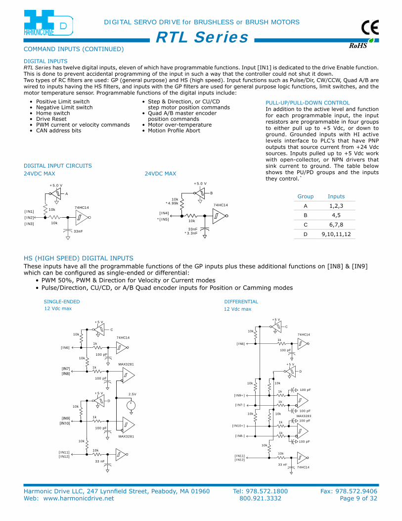
HS (HiGH SPeeD) DiGiTAL inPuTSThese inputs have all the programmable functions of the GP inputs plus these additional functions on [in8] & [in9] which can be configured as single-ended or differential:
• PWM 50%, PWM & Direction for Velocity or Current modes• Pulse/Direction, Cu/CD, or A/B Quad encoder inputs for Position or Camming modes
DiFFerenTiALSinGLe-enDeD12 Vdc max 12 Vdc max
100 pF
1k
+5 V
C10k
10k
10k
74HC14
[IN6]
[IN7-]
+5 V
100 pF
100 pF
100 pF
100 pF
10k
[IN9+]
[IN10+]
[IN8-]
1k
1k
1k
1k
10k
10k
33 nF
10k
74HC14
MAX3283
[IN11][IN12]
D
100 pF
1k
2.5V+5 V
10k100 pF
1k
+5 V
C
D
10k
[IN6]
74HC14
MAX3281
33 nF
10k
10k
10k
[IN11][IN12]
+
[IN7][IN8]
100 pF
1k
MAX3281
[IN9][IN10]
33nF
10k
10k 74HC14[IN1]
[IN2]
[IN3]
A
+5.0 V
33nF*3.3nF
10k
10k*4.99k 74HC14
[IN4]
*[IN5]
+5.0 V
B
DiGiTAL inPuTSRTL Series has twelve digital inputs, eleven of which have programmable functions. input [in1] is dedicated to the drive enable function. This is done to prevent accidental programming of the input in such a way that the controller could not shut it down.Two types of rC filters are used: GP (general purpose) and HS (high speed). input functions such as Pulse/Dir, CW/CCW, Quad A/B are wired to inputs having the HS filters, and inputs with the GP filters are used for general purpose logic functions, limit switches, and the motor temperature sensor. Programmable functions of the digital inputs include:
• Positive Limit switch • Step & Direction, or Cu/CD • negative Limit switch step motor position commands • Home switch • Quad A/B master encoder • Drive reset position commands • PWM current or velocity commands • Motor over-temperature • CAn address bits • Motion Profile Abort
DiGiTAL inPuT CirCuiTS24VDC MAX 24VDC MAX
Group inputs
A 1,2,3
B 4,5
C 6,7,8
D 9,10,11,12
PuLL-uP/PuLL-DoWn ConTroLin addition to the active level and function for each programmable input, the input resistors are programmable in four groups to either pull up to +5 Vdc, or down to ground. Grounded inputs with Hi active levels interface to PLC’s that have PnP outputs that source current from +24 Vdc sources. inputs pulled up to +5 Vdc work with open-collector, or nPn drivers that sink current to ground. The table below shows the Pu/PD groups and the inputs they control.`
RoHS
DIGITAL SERVO DRIVE for BRUSHLESS or BRUSH MOTORS
Harmonic Drive LLC, 247 Lynnfield Street, Peabody, MA 01960 Tel: 978.572.1800 Fax: 978.572.9406Web: www.harmonicdrive.net 800.921.3332 Page 10 of 32
RTL Series
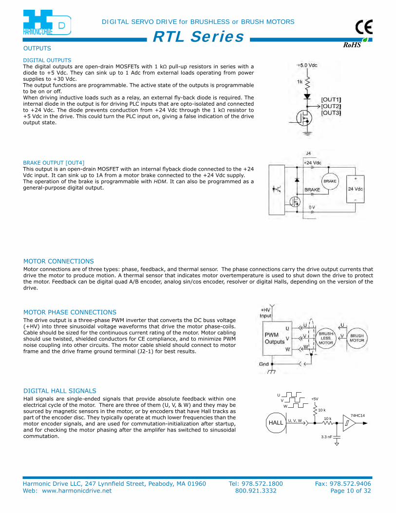
DiGiTAL HALL SiGnALSHall signals are single-ended signals that provide absolute feedback within one electrical cycle of the motor. There are three of them (u, V, & W) and they may be sourced by magnetic sensors in the motor, or by encoders that have Hall tracks as part of the encoder disc. They typically operate at much lower frequencies than the motor encoder signals, and are used for commutation-initialization after startup, and for checking the motor phasing after the amplifer has switched to sinusoidal commutation.
HALL U, V, W 10 k
3.3 nF
74HC14
+5V
10 k
UV
W
DiGiTAL ouTPuTSThe digital outputs are open-drain MoSFeTs with 1 kΩ pull-up resistors in series with a diode to +5 Vdc. They can sink up to 1 Adc from external loads operating from power supplies to +30 Vdc.The output functions are programmable. The active state of the outputs is programmable to be on or off.When driving inductive loads such as a relay, an external fly-back diode is required. The internal diode in the output is for driving PLC inputs that are opto-isolated and connected to +24 Vdc. The diode prevents conduction from +24 Vdc through the 1 kΩ resistor to +5 Vdc in the drive. This could turn the PLC input on, giving a false indication of the drive output state.
BrAke ouTPuT [ouT4]This output is an open-drain MoSFeT with an internal flyback diode connected to the +24 Vdc input. it can sink up to 1A from a motor brake connected to the +24 Vdc supply.The operation of the brake is programmable with HDM. it can also be programmed as a general-purpose digital output.
ouTPuTS
MoTor PHASe ConneCTionSThe drive output is a three-phase PWM inverter that converts the DC buss voltage (+HV) into three sinusoidal voltage waveforms that drive the motor phase-coils. Cable should be sized for the continuous current rating of the motor. Motor cabling should use twisted, shielded conductors for Ce compliance, and to minimize PWM noise coupling into other circuits. The motor cable shield should connect to motor frame and the drive frame ground terminal (J2-1) for best results.
MoTor ConneCTionSMotor connections are of three types: phase, feedback, and thermal sensor. The phase connections carry the drive output currents that drive the motor to produce motion. A thermal sensor that indicates motor overtemperature is used to shut down the drive to protect the motor. Feedback can be digital quad A/B encoder, analog sin/cos encoder, resolver or digital Halls, depending on the version of the drive.
RoHS
DIGITAL SERVO DRIVE for BRUSHLESS or BRUSH MOTORS
Harmonic Drive LLC, 247 Lynnfield Street, Peabody, MA 01960 Tel: 978.572.1800 Fax: 978.572.9406Web: www.harmonicdrive.net 800.921.3332 Page 11 of 32
RTL Series
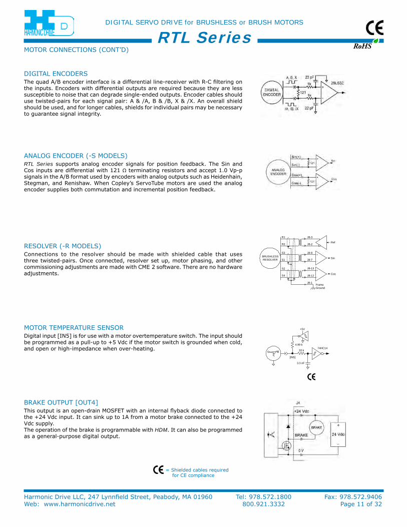
reSoLVer (-r MoDeLS)Connections to the resolver should be made with shielded cable that uses three twisted-pairs. once connected, resolver set up, motor phasing, and other commissioning adjustments are made with CMe 2 software. There are no hardware adjustments.
J8-8BRUSHLESSRESOLVER
-
+
-
+J8-13
J8-12
Sin
Cos
J8-7
J8-3
J8-2Ref
R1
R2
S3
S1
S2
S4
FrameGround
J8-1
AnALoG enCoDer (-S MoDeLS)RTL Series supports analog encoder signals for position feedback. The Sin and Cos inputs are differential with 121 Ω terminating resistors and accept 1.0 Vp-p signals in the A/B format used by encoders with analog outputs such as Heidenhain, Stegman, and renishaw. When Copley’s ServoTube motors are used the analog encoder supplies both commutation and incremental position feedback.
DiGiTAL enCoDerSThe quad A/B encoder interface is a differential line-receiver with r-C filtering on the inputs. encoders with differential outputs are required because they are less susceptible to noise that can degrade single-ended outputs. encoder cables should use twisted-pairs for each signal pair: A & /A, B & /B, X & /X. An overall shield should be used, and for longer cables, shields for individual pairs may be necessary to guarantee signal integrity.
10 k
3.3 nF
74HC14
+5V
4.99 k
[IN5]
MoTor TeMPerATure SenSorDigital input [in5] is for use with a motor overtemperature switch. The input should be programmed as a pull-up to +5 Vdc if the motor switch is grounded when cold, and open or high-impedance when over-heating.
= Shielded cables required for Ce compliance
BrAke ouTPuT [ouT4]This output is an open-drain MoSFeT with an internal flyback diode connected to the +24 Vdc input. it can sink up to 1A from a motor brake connected to the +24 Vdc supply.The operation of the brake is programmable with HDM. it can also be programmed as a general-purpose digital output.
MoTor ConneCTionS (ConT’D)
RoHS
DIGITAL SERVO DRIVE for BRUSHLESS or BRUSH MOTORS
Harmonic Drive LLC, 247 Lynnfield Street, Peabody, MA 01960 Tel: 978.572.1800 Fax: 978.572.9406Web: www.harmonicdrive.net 800.921.3332 Page 12 of 32
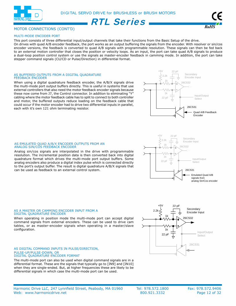
RTL SeriesMuLTi-MoDe enCoDer PorTThis port consists of three differential input/output channels that take their functions from the Basic Setup of the drive.on drives with quad A/B encoder feedback, the port works as an output buffering the signals from the encoder. With resolver or sin/cos encoder versions, the feedback is converted to quad A/B signals with programmable resolution. These signals can then be fed back to an external motion controller that closes the position or velocity loops. As an input, the port can take quad A/B signals to produce a dual-loop position control system or use the signals as master-encoder feedback in camming mode. in addition, the port can take stepper command signals (Cu/CD or Pulse/Direction) in differential format.
1k
22 pF
22 pF
2.2k SecondaryEncoder Input
Input/OutputSelect
Quad A/B FeedbackEncoder
26CS31
26CS32
+5V
1k
1k
22 pF
22 pF
2.2k SecondaryEncoder Input
Input/OutputSelect
Emulated Quad A/Bsignals from analog Sin/Cos encoderor resolver
26CS31
26CS32
+5V
1k
1k
22 pF
22 pF
2.2k SecondaryEncoder Input
Input/OutputSelect
26CS31
26CS32
+5V
1k
AS BuFFereD ouTPuTS FroM A DiGiTAL QuADrATure FeeDBACk enCoDerWhen using a digital quadrature feedback encoder, the A/B/X signals drive the multi-mode port output buffers directly. This is useful in systems that use external controllers that also need the motor feedback encoder signals because these now come from J7, the Control connector. in addition to eliminating “y” cabling where the motor feedback cable has to split to connect to both controller and motor, the buffered outputs reduce loading on the feedback cable that could occur if the motor encoder had to drive two differential inputs in parallel, each with it’s own 121 ohm terminating resistor.
AS eMuLATeD QuAD A/B/X enCoDer ouTPuTS FroM An AnALoG Sin/CoS FeeDBACk enCoDerAnalog sin/cos signals are interpolated in the drive with programmable resolution. The incremental position data is then converted back into digital quadrature format which drives the multi-mode port output buffers. Some analog encoders also produce a digital index pulse which is connected directly to the port’s output buffer. The result is digital quadrature A/B/X signals that can be used as feedback to an external control system.
AS A MASTer or CAMMinG enCoDer inPuT FroM A DiGiTAL QuADrATure enCoDerWhen operating in position mode the multi-mode port can accept digital command signals from external encoders. These can be used to drive cam tables, or as master-encoder signals when operating in a master/slave configuration.
AS DiGiTAL CoMMAnD inPuTS in PuLSe/DireCTion,PuLSe-uP/PuLSe-DoWn, or DiGiTAL QuADrATure enCoDer ForMATThe multi-mode port can also be used when digital command signals are in a differential format. These are the signals that typically go to [in9] and [in10] when they are single-ended. But, at higher frequencies these are likely to be differential signals in which case the multi-mode port can be used.
MoTor ConneCTionS (ConT’D)
RoHS
DIGITAL SERVO DRIVE for BRUSHLESS or BRUSH MOTORS
Harmonic Drive LLC, 247 Lynnfield Street, Peabody, MA 01960 Tel: 978.572.1800 Fax: 978.572.9406Web: www.harmonicdrive.net 800.921.3332 Page 13 of 32
RTL Series
DANGER: HIGH VOLTAGECIRCUITS ON J1, J2, & J3ARE CONNECTED TOMAINS POWER
7
8
11
12
13
DIGITALENCODER
DIGITALHALLS
TEMPSENSOR
7
6
5
12
11
4
14
2
3
13
1-HV
J8
21
22
23
26
24
25
1
14
1
20
19
2
+5 Vdc @ 400 mA
Signal Ground
15 Signal Ground
Ref(-)
Multi-ModeEncoder
Port
A
/A
B
/B
X
/X
Frame Ground
+24V
BRAKE
RTN J4
Earth
Fuse
J1
4L3
1
AC MAINS:100 to 240 Vac1Ø or 3Ø47 to 63 Hz
H
1
4
5
J3REGEN+
REGEN-
Frame Ground
2
3
J2
U
V
W
BRUSHLESSMOTOR
* Fuse
* Fuse
4
3
2
1
Mot U
Mot V
Mot W
Frame Ground
3
L2 N2
1L1
L3
L2
L1
[IN7] HS
[IN8] HS
[IN9] HS
[IN10] HS
10
[IN1] Enable
[IN4] GP
[IN2] GP
[IN3] GP
3 Ref(+) J7±10 VdcAnalog
Reference
[IN6] HS
9 [IN12] GP
8 [IN11] GP
17 [OUT2]
16 [OUT1]
18 [OUT3]
FrameGnd
10Motemp [IN5]
Signal Ground 15
Signal Ground 5
BRAKE
+24 Vdc0.5 Adc
+
-
LIN
EFI
LTE
R
* Fuse
* Fuse
Control Power SupplyRequired for
Drive Operation
Drive mounting screw
+5 Vdc 4
+5 Vdc 2
Hall W 9
Hall V 6
Hall U 3
A
/A
B
/B
X
/X
/A
A
/B
B
/X
Vcc
0V
X
Outputs BufferedQuad A/B fromEncoder
* Optional
(noTe 1)
(noTe 1)
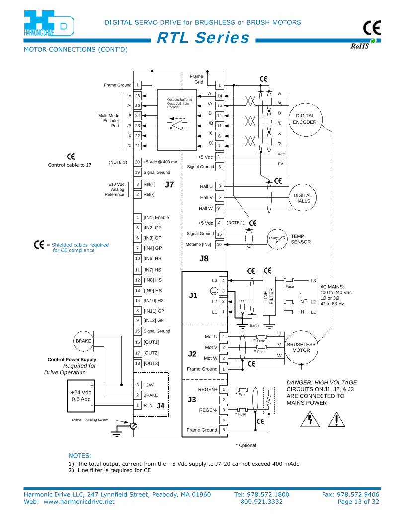
= Shielded cables required for Ce compliance
Control cable to J7
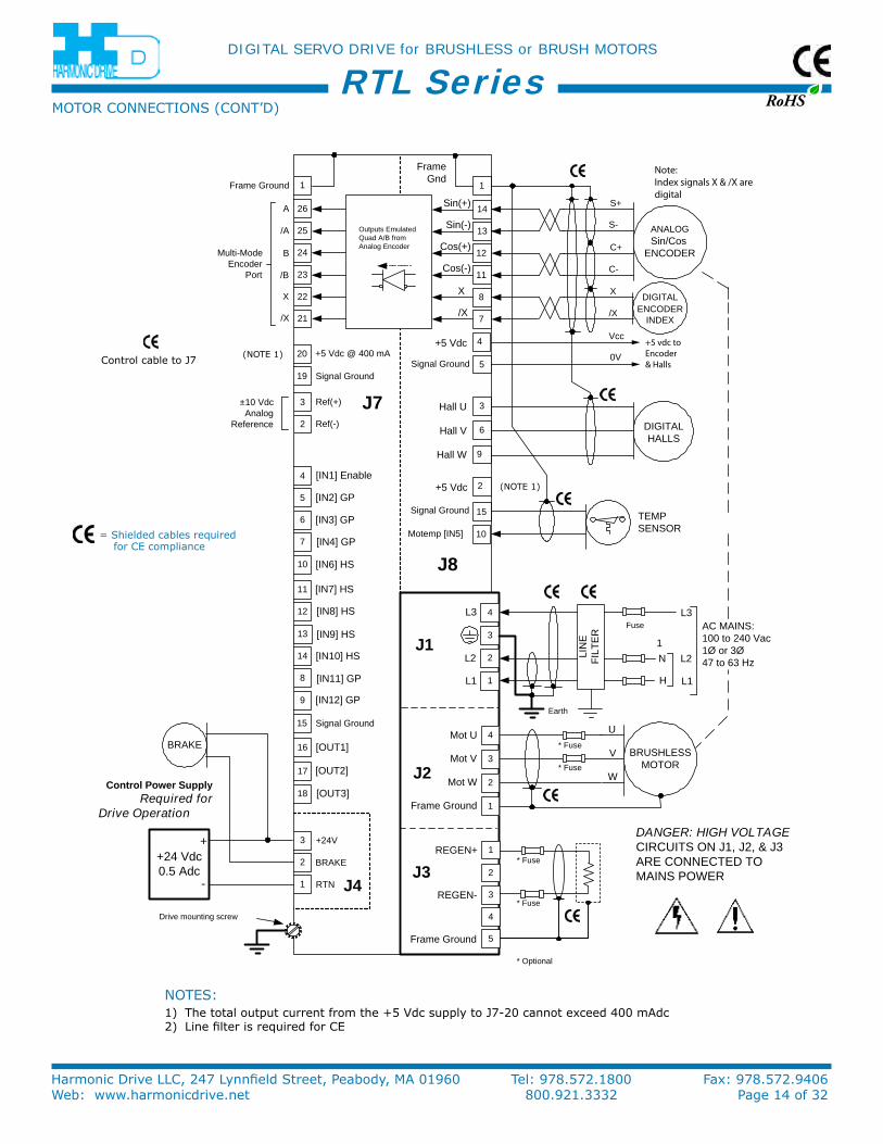
noTeS:1) The total output current from the +5 Vdc supply to J7-20 cannot exceed 400 mAdc2) Line filter is required for Ce
MoTor ConneCTionS (ConT’D)
RoHS
DIGITAL SERVO DRIVE for BRUSHLESS or BRUSH MOTORS
Harmonic Drive LLC, 247 Lynnfield Street, Peabody, MA 01960 Tel: 978.572.1800 Fax: 978.572.9406Web: www.harmonicdrive.net 800.921.3332 Page 14 of 32
RTL Series
DANGER: HIGH VOLTAGECIRCUITS ON J1, J2, & J3ARE CONNECTED TOMAINS POWER
7
8
11
12
13 ANALOGSin/Cos
ENCODER
DIGITALENCODER
INDEX
DIGITALHALLS
TEMPSENSOR
7
6
5
12
11
4
14
2
3
13
1-HV
J8
21
22
23
26
24
25
1
14
1
20
19
2
+5 Vdc @ 400 mA
Signal Ground
15 Signal Ground
Ref(-)
Multi-ModeEncoder
Port
A
/A
B
/B
X
/X
Frame Ground
+24V
BRAKE
RTN J4
Earth
Fuse
J1
4L3
1
AC MAINS:100 to 240 Vac1Ø or 3Ø47 to 63 Hz
H
1
4
5
J3REGEN+
REGEN-
Frame Ground
2
3
J2
U
V
W
BRUSHLESSMOTOR
* Fuse
* Fuse
4
3
2
1
Mot U
Mot V
Mot W
Frame Ground
3
L2 N2
1L1
L3
L2
L1
[IN7] HS
[IN8] HS
[IN9] HS
[IN10] HS
10
[IN1] Enable
[IN4] GP
[IN2] GP
[IN3] GP
3 Ref(+) J7±10 VdcAnalog
Reference
[IN6] HS
9 [IN12] GP
8 [IN11] GP
17 [OUT2]
16 [OUT1]
18 [OUT3]
FrameGnd
10Motemp [IN5]
Signal Ground 15
Signal Ground 5
BRAKE
+24 Vdc0.5 Adc
+
-
LIN
EFI
LTE
R
* Fuse
* Optional
* Fuse
Control Power SupplyRequired for
Drive Operation
Drive mounting screw
+5 Vdc 4
+5 Vdc 2
Hall W 9
Hall V 6
Hall U 3
Sin(+)
Sin(-)
Cos(+)
Cos(-)
S-
X
/X
S+
C-
C+
/X
Vcc
0V
X
Outputs EmulatedQuad A/B fromAnalog Encoder
Note:Index signals X & /X aredigital
+5 vdc to Encoder& Halls
(noTe 1)
(noTe 1)
noTeS:1) The total output current from the +5 Vdc supply to J7-20 cannot exceed 400 mAdc2) Line filter is required for Ce
= Shielded cables required for Ce compliance
Control cable to J7
MoTor ConneCTionS (ConT’D)

RoHS
DIGITAL SERVO DRIVE for BRUSHLESS or BRUSH MOTORS
Harmonic Drive LLC, 247 Lynnfield Street, Peabody, MA 01960 Tel: 978.572.1800 Fax: 978.572.9406Web: www.harmonicdrive.net 800.921.3332 Page 15 of 32
RTL Series
* Optional
DANGER: HIGH VOLTAGECIRCUITS ON J1, J2, & J3ARE CONNECTED TOMAINS POWER
10Motemp [IN5]
12
13
7
8
2
BRUSHLESSRESOLVER
7
6
5
12
11
4
14
2
3
13
1-HV
J8
21
22
23
26
24
25
11
3
1
20
19
2
+5 Vdc @ 400 mA
Signal Ground
Signal Ground
Signal Ground
15 Signal Ground
Ref(-)
Multi-ModeEncoder
Port
A
/A
B
/B
X
/X
Frame Ground
+24V
BRAKE
RTN J4
Earth
Fuse
J1
4L3
1
AC MAINS:100 to 240 Vac1Ø or 3Ø47 to 63 Hz
H
1
4
5
J3REGEN+
REGEN-
Frame Ground
2
3
J2
U
V
W
BRUSHLESSMOTOR
* Fuse
* Fuse
4
3
2
1
Mot U
Mot V
Mot W
Frame Ground
3
L2 N2
1L1
L3
L2
L1
[IN7] HS
[IN8] HS
[IN9] HS
[IN10] HS
10
[IN1] Enable
[IN4] GP
[IN2] GP
[IN3] GP
3 Ref(+) J7±10 VdcAnalog
Reference
[IN6] HS
9 [IN12] GP
8 [IN11] GP
17 [OUT2]
16 [OUT1]
18 [OUT3]
FrameGnd
FrameGnd
No Connect
No Connect
No Connect
5
15
BRAKE
+24 Vdc0.5 Adc
+
-
LIN
EFI
LTE
R
* Fuse
* Fuse
Control Power SupplyRequired for
Drive Operation
Drive mounting screw
4
9
14
R1
R2
S3
S1
S2
S4
R2
R1
S1
S3
S4
S2
Outputs EmulatedQuad A/B fromResolver
Inputs SecondaryPosition Encoder
6
1(noTe 1)
noTeS:1) The total output current from the +5 Vdc supply to J7-20 cannot exceed 400 mAdc2) Line filter is required for Ce
= Shielded cables required for Ce compliance
Control cable to J7
MoTor ConneCTionS (ConT’D)
RoHS
DIGITAL SERVO DRIVE for BRUSHLESS or BRUSH MOTORS
Harmonic Drive LLC, 247 Lynnfield Street, Peabody, MA 01960 Tel: 978.572.1800 Fax: 978.572.9406Web: www.harmonicdrive.net 800.921.3332 Page 16 of 32
RTL Series
~
~ -
+
~+
REGEN(-) REGEN(+)
SHIELD
U
V
W
J2
DC BUSS(+)
DC BUSS(-)
J3
1760 µFL1
MAINSL3
L2J1
PWMSTAGE
POWERCONTROL
ISOLATION BARRIER
SHIELD
+5 Vdc
SIGNAL GND
RESOLVERDRIVE &DECODING
J8
CONTROLLOGIC
+5 Vdc
ENABLE [IN1]
SIGNAL GND
CONTROLSIGNALGROUND
CONTROLSYSTEM
J7
GROUND+24 Vdc
+24VDC BRAKE
+24 VdcJ4
RTNCntrl
BRAKE
DC/DCConverter
&
POWER
LOGIC
SIGNAL
DC/DC
(SAFETY GROUND)
PWMINVERTER
MOTOR
RESOLVER
CASE
FRAME GROUND
FRAME GROUND
20
40
60
80
100
120
240220200180160140120100
Energy Absorption vs.Mains Voltage
Mains Voltage (Vac)
Ener
gy
Ab
sorp
tio
n (
W·s
)
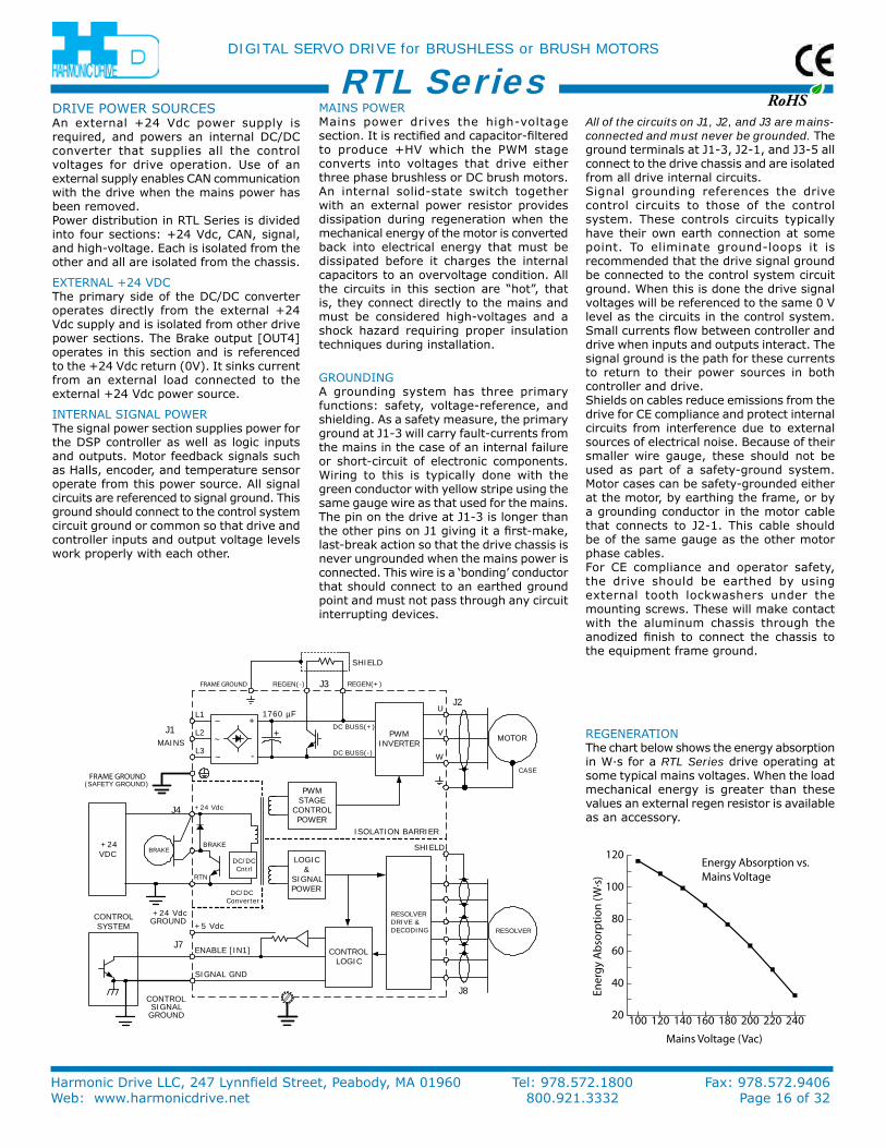
GrounDinGA grounding system has three primary functions: safety, voltage-reference, and shielding. As a safety measure, the primary ground at J1-3 will carry fault-currents from the mains in the case of an internal failure or short-circuit of electronic components. Wiring to this is typically done with the green conductor with yellow stripe using the same gauge wire as that used for the mains. The pin on the drive at J1-3 is longer than the other pins on J1 giving it a first-make, last-break action so that the drive chassis is never ungrounded when the mains power is connected. This wire is a ‘bonding’ conductor that should connect to an earthed ground point and must not pass through any circuit interrupting devices.
All of the circuits on J1, J2, and J3 are mains-connected and must never be grounded. The ground terminals at J1-3, J2-1, and J3-5 all connect to the drive chassis and are isolated from all drive internal circuits.Signal grounding references the drive control circuits to those of the control system. These controls circuits typically have their own earth connection at some point. To eliminate ground-loops it is recommended that the drive signal ground be connected to the control system circuit ground. When this is done the drive signal voltages will be referenced to the same 0 V level as the circuits in the control system. Small currents flow between controller and drive when inputs and outputs interact. The signal ground is the path for these currents to return to their power sources in both controller and drive.Shields on cables reduce emissions from the drive for Ce compliance and protect internal circuits from interference due to external sources of electrical noise. Because of their smaller wire gauge, these should not be used as part of a safety-ground system. Motor cases can be safety-grounded either at the motor, by earthing the frame, or by a grounding conductor in the motor cable that connects to J2-1. This cable should be of the same gauge as the other motor phase cables.For Ce compliance and operator safety, the drive should be earthed by using external tooth lockwashers under the mounting screws. These will make contact with the aluminum chassis through the anodized finish to connect the chassis to the equipment frame ground.
DriVe PoWer SourCeSAn external +24 Vdc power supply is required, and powers an internal DC/DC converter that supplies all the control voltages for drive operation. use of an external supply enables CAn communication with the drive when the mains power has been removed.Power distribution in rTL Series is divided into four sections: +24 Vdc, CAn, signal, and high-voltage. each is isolated from the other and all are isolated from the chassis.
eXTernAL +24 VDCThe primary side of the DC/DC converter operates directly from the external +24 Vdc supply and is isolated from other drive power sections. The Brake output [ouT4] operates in this section and is referenced to the +24 Vdc return (0V). it sinks current from an external load connected to the external +24 Vdc power source.
inTernAL SiGnAL PoWerThe signal power section supplies power for the DSP controller as well as logic inputs and outputs. Motor feedback signals such as Halls, encoder, and temperature sensor operate from this power source. All signal circuits are referenced to signal ground. This ground should connect to the control system circuit ground or common so that drive and controller inputs and output voltage levels work properly with each other.
MAinS PoWerMains power drives the high-voltage section. it is rectified and capacitor-filtered to produce +HV which the PWM stage converts into voltages that drive either three phase brushless or DC brush motors. An internal solid-state switch together with an external power resistor provides dissipation during regeneration when the mechanical energy of the motor is converted back into electrical energy that must be dissipated before it charges the internal capacitors to an overvoltage condition. All the circuits in this section are “hot”, that is, they connect directly to the mains and must be considered high-voltages and a shock hazard requiring proper insulation techniques during installation.
reGenerATionThe chart below shows the energy absorption in W·s for a RTL Series drive operating at some typical mains voltages. When the load mechanical energy is greater than these values an external regen resistor is available as an accessory.
RoHS
DIGITAL SERVO DRIVE for BRUSHLESS or BRUSH MOTORS
Harmonic Drive LLC, 247 Lynnfield Street, Peabody, MA 01960 Tel: 978.572.1800 Fax: 978.572.9406Web: www.harmonicdrive.net 800.921.3332 Page 17 of 32
RTL Series
3 TURNSAROUNDTOROID
INDUCTOR
MOTOR
MAINS
REGEN
CONTROLLER
RTL
FEEDBACK
LINEFILTER
J1
J2
J8J7
J3J424 VPOWERSUPPLY
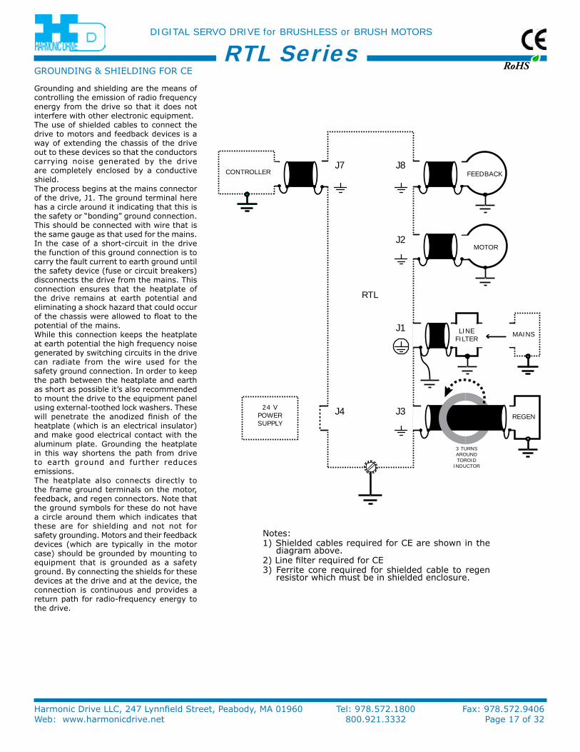
Grounding and shielding are the means of controlling the emission of radio frequency energy from the drive so that it does not interfere with other electronic equipment.The use of shielded cables to connect the drive to motors and feedback devices is a way of extending the chassis of the drive out to these devices so that the conductors carrying noise generated by the drive are completely enclosed by a conductive shield.The process begins at the mains connector of the drive, J1. The ground terminal here has a circle around it indicating that this is the safety or “bonding” ground connection. This should be connected with wire that is the same gauge as that used for the mains. in the case of a short-circuit in the drive the function of this ground connection is to carry the fault current to earth ground until the safety device (fuse or circuit breakers) disconnects the drive from the mains. This connection ensures that the heatplate of the drive remains at earth potential and eliminating a shock hazard that could occur of the chassis were allowed to float to the potential of the mains.While this connection keeps the heatplate at earth potential the high frequency noise generated by switching circuits in the drive can radiate from the wire used for the safety ground connection. in order to keep the path between the heatplate and earth as short as possible it’s also recommended to mount the drive to the equipment panel using external-toothed lock washers. These will penetrate the anodized finish of the heatplate (which is an electrical insulator) and make good electrical contact with the aluminum plate. Grounding the heatplate in this way shortens the path from drive to earth ground and further reduces emissions.The heatplate also connects directly to the frame ground terminals on the motor, feedback, and regen connectors. note that the ground symbols for these do not have a circle around them which indicates that these are for shielding and not not for safety grounding. Motors and their feedback devices (which are typically in the motor case) should be grounded by mounting to equipment that is grounded as a safety ground. By connecting the shields for these devices at the drive and at the device, the connection is continuous and provides a return path for radio-frequency energy to the drive.
notes:1) Shielded cables required for Ce are shown in the
diagram above.2) Line filter required for Ce3) Ferrite core required for shielded cable to regen
resistor which must be in shielded enclosure.
GrounDinG & SHieLDinG For Ce
RoHS
DIGITAL SERVO DRIVE for BRUSHLESS or BRUSH MOTORS
Harmonic Drive LLC, 247 Lynnfield Street, Peabody, MA 01960 Tel: 978.572.1800 Fax: 978.572.9406Web: www.harmonicdrive.net 800.921.3332 Page 18 of 32
RTL Series
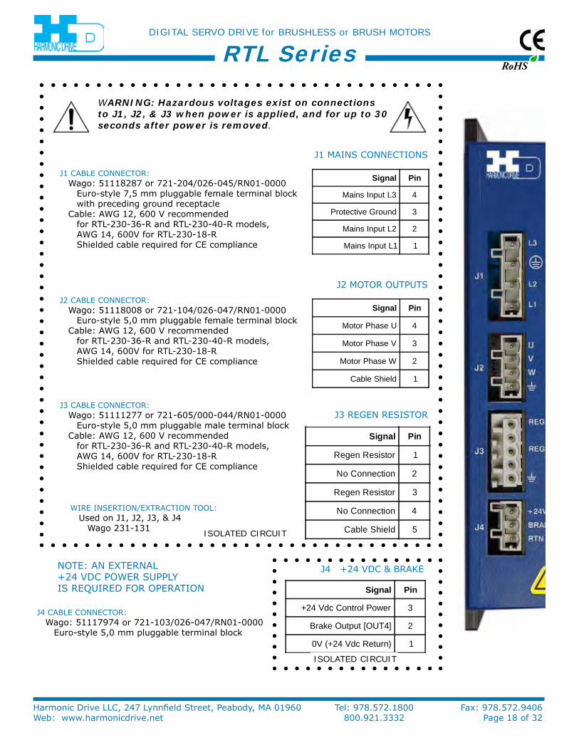
Signal Pin
Motor Phase U 4
Motor Phase V 3
Motor Phase W 2
Cable Shield 1
Signal Pin
Mains Input L3 4
Protective Ground 3
Mains Input L2 2
Mains Input L1 1
Signal Pin
Regen Resistor 1
No Connection 2
Regen Resistor 3
No Connection 4
Cable Shield 5
Signal Pin
+24 Vdc Control Power 3
Brake Output [OUT4] 2
0V (+24 Vdc Return) 1
J1 MAinS ConneCTionS
J2 MoTor ouTPuTS
J3 reGen reSiSTor
J4 +24 VDC & BrAke
J1 CABLe ConneCTor: Wago: 51118287 or 721-204/026-045/rn01-0000
euro-style 7,5 mm pluggable female terminal block with preceding ground receptacle
Cable: AWG 12, 600 V recommended for rTL-230-36-r and rTL-230-40-r models, AWG 14, 600V for rTL-230-18-r Shielded cable required for Ce compliance
J2 CABLe ConneCTor: Wago: 51118008 or 721-104/026-047/rn01-0000
euro-style 5,0 mm pluggable female terminal blockCable: AWG 12, 600 V recommended
for rTL-230-36-r and rTL-230-40-r models, AWG 14, 600V for rTL-230-18-r Shielded cable required for Ce compliance
J3 CABLe ConneCTor:Wago: 51111277 or 721-605/000-044/rn01-0000
euro-style 5,0 mm pluggable male terminal blockCable: AWG 12, 600 V recommended
for rTL-230-36-r and rTL-230-40-r models, AWG 14, 600V for rTL-230-18-r Shielded cable required for Ce compliance
WARNING: Hazardous voltages exist on connections to J1, J2, & J3 when power is applied, and for up to 30 seconds after power is removed.
Wire inSerTion/eXTrACTion TooL:used on J1, J2, J3, & J4
Wago 231-131ISOLATED CIRCUIT
ISOLATED CIRCUIT
J4 CABLe ConneCTor:Wago: 51117974 or 721-103/026-047/rn01-0000
euro-style 5,0 mm pluggable terminal block
noTe: An eXTernAL +24 VDC PoWer SuPPLy iS reQuireD For oPerATion

RoHS
DIGITAL SERVO DRIVE for BRUSHLESS or BRUSH MOTORS
Harmonic Drive LLC, 247 Lynnfield Street, Peabody, MA 01960 Tel: 978.572.1800 Fax: 978.572.9406Web: www.harmonicdrive.net 800.921.3332 Page 19 of 32
RTL Series
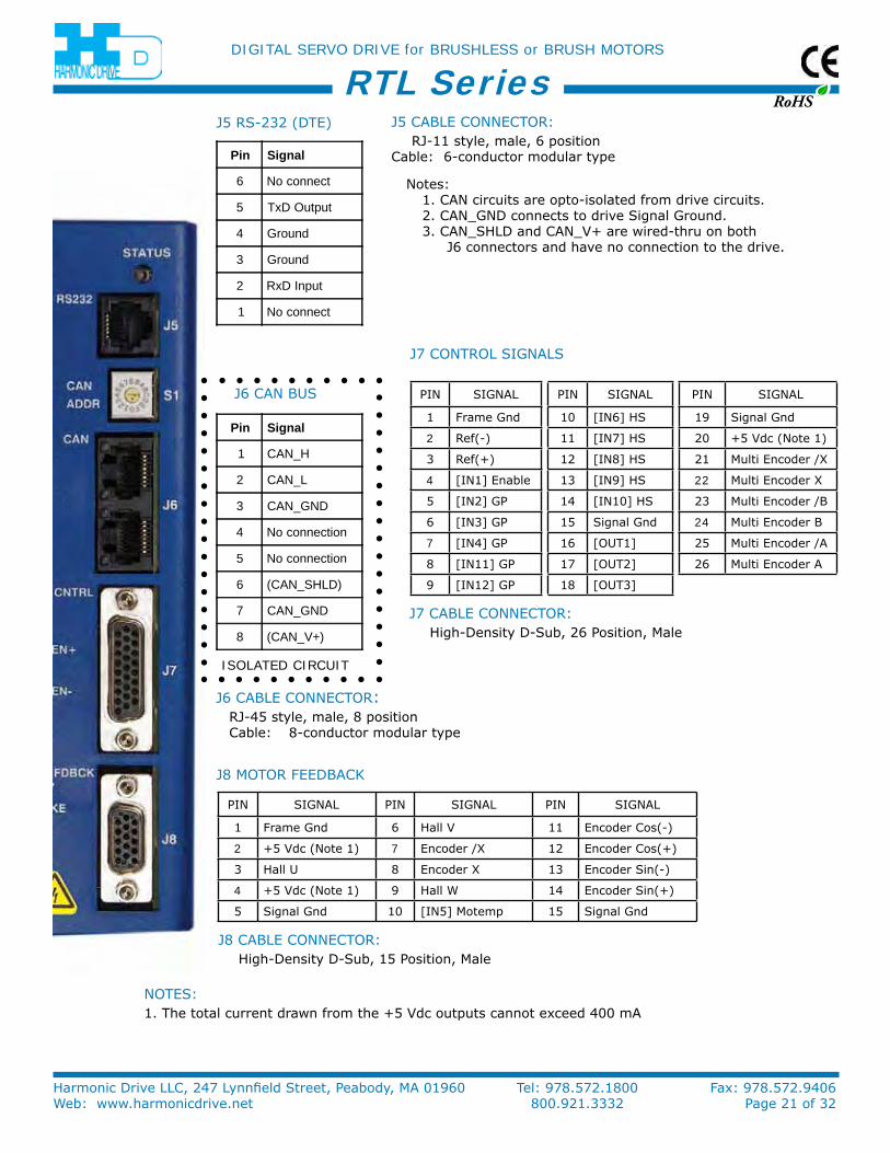
Pin SiGnAL Pin SiGnAL Pin SiGnAL
1 Frame Gnd 6 Hall V 11 encoder /B
2 +5 Vdc (note 1) 7 encoder /X 12 encoder B
3 Hall u 8 encoder X 13 encoder /A
4 +5 Vdc (note 1) 9 Hall W 14 encoder A
5 Signal Gnd 10 [in5] Motemp 15 Signal Gnd
Pin SiGnAL Pin SiGnAL Pin SiGnAL
1 Frame Gnd 10 [in6] HS 19 Signal Gnd
2 ref(-) 11 [in7] HS 20 +5 Vdc (note 1)
3 ref(+) 12 [in8] HS 21 Multi encoder /X
4 [in1] enable 13 [in9] HS 22 Multi encoder X
5 [in2] GP 14 [in10] HS 23 Multi encoder /B
6 [in3] GP 15 Signal Gnd 24 Multi encoder B
7 [in4] GP 16 [ouT1] 25 Multi encoder /A
8 [in11] GP 17 [ouT2] 26 Multi encoder A
9 [in12] GP 18 [ouT3]
Pin Signal
6 No connect
5 TxD Output
4 Ground
3 Ground
2 RxD Input
1 No connect
Pin Signal
1 CAN_H
2 CAN_L
3 CAN_GND
4 No connection
5 No connection
6 (CAN_SHLD)
7 CAN_GND
8 (CAN_V+)
J8 MoTor FeeDBACk
J7 ConTroL SiGnALS
J6 CAn BuS
J5 rS-232 (DTe)
ISOLATED CIRCUIT
notes:1. CAn circuits are opto-isolated from drive circuits. 2. CAn_GnD connects to drive Signal Ground. 3. CAn_SHLD and CAn_V+ are wired-thru on both J6 connectors and have no connection to the drive.
J5 CABLe ConneCTor: rJ-11 style, male, 6 position Cable: 6-conductor modular type
J6 CABLe ConneCTor:rJ-45 style, male, 8 position Cable: 8-conductor modular type
J7 CABLe ConneCTor: High-Density D-Sub, 26 Position, Male
J8 CABLe ConneCTor: High-Density D-Sub, 15 Position, Male
noTeS:1. The total current drawn from the +5 Vdc outputs cannot exceed 400 mA

RoHS
DIGITAL SERVO DRIVE for BRUSHLESS or BRUSH MOTORS
Harmonic Drive LLC, 247 Lynnfield Street, Peabody, MA 01960 Tel: 978.572.1800 Fax: 978.572.9406Web: www.harmonicdrive.net 800.921.3332 Page 20 of 32
RTL Series
Signal Pin
Motor Phase U 4
Motor Phase V 3
Motor Phase W 2
Cable Shield 1
Signal Pin
Mains Input L3 4
Protective Ground 3
Mains Input L2 2
Mains Input L1 1
Signal Pin
Regen Resistor 1
No Connection 2
Regen Resistor 3
No Connection 4
Cable Shield 5
Signal Pin
+24 Vdc Control Power 3
Brake Output [OUT4] 2
0V (+24 Vdc Return) 1
J1 MAinS ConneCTionS
J2 MoTor ouTPuTS
J3 reGen reSiSTor
J4 +24 VDC & BrAke
J1 CABLe ConneCTor: Wago: 51118287 or 721-204/026-045/rn01-0000
euro-style 7,5 mm pluggable female terminal block with preceding ground receptacle
Cable: AWG 12, 600 V recommended for rTL-230-36-r and rTL-230-40-r models, AWG 14, 600V for rTL-230-18-r Shielded cable required for Ce compliance
J2 CABLe ConneCTor: Wago: 51118008 or 721-104/026-047/rn01-0000
euro-style 5,0 mm pluggable female terminal blockCable: AWG 12, 600 V recommended
for rTL-230-36-r and rTL-230-40-r models, AWG 14, 600V for rTL-230-18-r Shielded cable required for Ce compliance
J3 CABLe ConneCTor:Wago: 51111277 or 721-605/000-043/rn01-0000
euro-style 5,0 mm pluggable male terminal blockCable: AWG 12, 600 V recommended
for rTL-230-36-r and rTL-230-40-r models, AWG 14, 600V for rTL-230-18-r Shielded cable required for Ce compliance
WARNING: Hazardous voltages exist on connections to J1, J2, & J3 when power is applied, and for up to 30 seconds after power is removed.
Wire inSerTion/eXTrACTion TooL:used on J1, J2, J3, & J4
Wago 231-131ISOLATED CIRCUIT
ISOLATED CIRCUIT
J4 CABLe ConneCTor:Wago: 51117974 or 721-103/026-047/rn01-0000
euro-style 5,0 mm pluggable terminal block
noTe: An eXTernAL +24 VDC PoWer SuPPLy iS reQuireD For oPerATion
RoHS
DIGITAL SERVO DRIVE for BRUSHLESS or BRUSH MOTORS
Harmonic Drive LLC, 247 Lynnfield Street, Peabody, MA 01960 Tel: 978.572.1800 Fax: 978.572.9406Web: www.harmonicdrive.net 800.921.3332 Page 21 of 32
RTL Series
Pin SiGnAL Pin SiGnAL Pin SiGnAL
1 Frame Gnd 6 Hall V 11 encoder Cos(-)
2 +5 Vdc (note 1) 7 encoder /X 12 encoder Cos(+)
3 Hall u 8 encoder X 13 encoder Sin(-)
4 +5 Vdc (note 1) 9 Hall W 14 encoder Sin(+)
5 Signal Gnd 10 [in5] Motemp 15 Signal Gnd
Pin SiGnAL Pin SiGnAL Pin SiGnAL
1 Frame Gnd 10 [in6] HS 19 Signal Gnd
2 ref(-) 11 [in7] HS 20 +5 Vdc (note 1)
3 ref(+) 12 [in8] HS 21 Multi encoder /X
4 [in1] enable 13 [in9] HS 22 Multi encoder X
5 [in2] GP 14 [in10] HS 23 Multi encoder /B
6 [in3] GP 15 Signal Gnd 24 Multi encoder B
7 [in4] GP 16 [ouT1] 25 Multi encoder /A
8 [in11] GP 17 [ouT2] 26 Multi encoder A
9 [in12] GP 18 [ouT3]
noTeS:1. The total current drawn from the +5 Vdc outputs cannot exceed 400 mA
Pin Signal
6 No connect
5 TxD Output
4 Ground
3 Ground
2 RxD Input
1 No connect
Pin Signal
1 CAN_H
2 CAN_L
3 CAN_GND
4 No connection
5 No connection
6 (CAN_SHLD)
7 CAN_GND
8 (CAN_V+)
J8 MoTor FeeDBACk
J7 ConTroL SiGnALS
J6 CAn BuS
J5 rS-232 (DTe)
ISOLATED CIRCUIT
notes:1. CAn circuits are opto-isolated from drive circuits. 2. CAn_GnD connects to drive Signal Ground. 3. CAn_SHLD and CAn_V+ are wired-thru on both J6 connectors and have no connection to the drive.
J5 CABLe ConneCTor: rJ-11 style, male, 6 position Cable: 6-conductor modular type
J6 CABLe ConneCTor:rJ-45 style, male, 8 position Cable: 8-conductor modular type
J7 CABLe ConneCTor: High-Density D-Sub, 26 Position, Male
J8 CABLe ConneCTor: High-Density D-Sub, 15 Position, Male

RoHS
DIGITAL SERVO DRIVE for BRUSHLESS or BRUSH MOTORS
Harmonic Drive LLC, 247 Lynnfield Street, Peabody, MA 01960 Tel: 978.572.1800 Fax: 978.572.9406Web: www.harmonicdrive.net 800.921.3332 Page 22 of 32
RTL Series
Signal Pin
Motor Phase U 4
Motor Phase V 3
Motor Phase W 2
Cable Shield 1
Signal Pin
Mains Input L3 4
Protective Ground 3
Mains Input L2 2
Mains Input L1 1
Signal Pin
Regen Resistor 1
No Connection 2
Regen Resistor 3
No Connection 4
Cable Shield 5
Signal Pin
+24 Vdc Control Power 3
Brake Output [OUT4] 2
0V (+24 Vdc Return) 1
J1 MAinS ConneCTionS
J2 MoTor ouTPuTS
J3 reGen reSiSTor
J4 +24 VDC & BrAke
J1 CABLe ConneCTor: Wago: 51118287 or 721-204/026-045/rn01-0000
euro-style 7,5 mm pluggable female terminal block with preceding ground receptacle
Cable: AWG 12, 600 V recommended for rTL-230-36-r and rTL-230-40-r models, AWG 14, 600V for rTL-230-18-r Shielded cable required for Ce compliance
J2 CABLe ConneCTor: Wago: 51118008 or 721-104/026-047/rn01-0000
euro-style 5,0 mm pluggable female terminal blockCable: AWG 12, 600 V recommended
for rTL-230-36-r and rTL-230-40-r models, AWG 14, 600V for rTL-230-18-r Shielded cable required for Ce compliance
J3 CABLe ConneCTor:Wago: 51111277 or 721-605/000-043/rn01-0000
euro-style 5,0 mm pluggable male terminal blockCable: AWG 12, 600 V recommended
for rTL-230-36-r and rTL-230-40-r models, AWG 14, 600V for rTL-230-18-r Shielded cable required for Ce compliance
WARNING: Hazardous voltages exist on connections to J1, J2, & J3 when power is applied, and for up to 30 seconds after power is removed.
Wire inSerTion/eXTrACTion TooL:used on J1, J2, J3, & J4
Wago 231-131ISOLATED CIRCUIT
ISOLATED CIRCUIT
J4 CABLe ConneCTor:Wago: 51117974 or 721-103/026-047/rn01-0000
euro-style 5,0 mm pluggable terminal block
noTe: An eXTernAL +24 VDC PoWer SuPPLy iS reQuireD For oPerATion
RoHS
DIGITAL SERVO DRIVE for BRUSHLESS or BRUSH MOTORS
Harmonic Drive LLC, 247 Lynnfield Street, Peabody, MA 01960 Tel: 978.572.1800 Fax: 978.572.9406Web: www.harmonicdrive.net 800.921.3332 Page 23 of 32
RTL Series
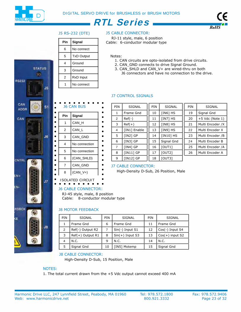
Pin SiGnAL Pin SiGnAL Pin SiGnAL
1 Frame Gnd 6 Frame Gnd 11 Frame Gnd
2 ref(-) output r2 7 Sin(-) input S1 12 Cos(-) input S4
3 ref(+) output r1 8 Sin(+) input S3 13 Cos(+) input S2
4 n.C. 9 n.C. 14 n.C.
5 Signal Gnd 10 [in5] Motemp 15 Signal Gnd
Pin SiGnAL Pin SiGnAL Pin SiGnAL
1 Frame Gnd 10 [in6] HS 19 Signal Gnd
2 ref(-) 11 [in7] HS 20 +5 Vdc (note 1)
3 ref(+) 12 [in8] HS 21 Multi encoder /X
4 [in1] enable 13 [in9] HS 22 Multi encoder X
5 [in2] GP 14 [in10] HS 23 Multi encoder /B
6 [in3] GP 15 Signal Gnd 24 Multi encoder B
7 [in4] GP 16 [ouT1] 25 Multi encoder /A
8 [in11] GP 17 [ouT2] 26 Multi encoder A
9 [in12] GP 18 [ouT3]
noTeS:1. The total current drawn from the +5 Vdc output cannot exceed 400 mA
Pin Signal
6 No connect
5 TxD Output
4 Ground
3 Ground
2 RxD Input
1 No connect
Pin Signal
1 CAN_H
2 CAN_L
3 CAN_GND
4 No connection
5 No connection
6 (CAN_SHLD)
7 CAN_GND
8 (CAN_V+)
J8 MoTor FeeDBACk
J7 ConTroL SiGnALS
J6 CAn BuS
J5 rS-232 (DTe)
ISOLATED CIRCUIT
notes:1. CAn circuits are opto-isolated from drive circuits. 2. CAn_GnD connects to drive Signal Ground. 3. CAn_SHLD and CAn_V+ are wired-thru on both J6 connectors and have no connection to the drive.
J5 CABLe ConneCTor: rJ-11 style, male, 6 position Cable: 6-conductor modular type
J6 CABLe ConneCTor:rJ-45 style, male, 8 position Cable: 8-conductor modular type
J7 CABLe ConneCTor: High-Density D-Sub, 26 Position, Male
J8 CABLe ConneCTor: High-Density D-Sub, 15 Position, Male
RoHS
DIGITAL SERVO DRIVE for BRUSHLESS or BRUSH MOTORS
Harmonic Drive LLC, 247 Lynnfield Street, Peabody, MA 01960 Tel: 978.572.1800 Fax: 978.572.9406Web: www.harmonicdrive.net 800.921.3332 Page 24 of 32
RTL Series
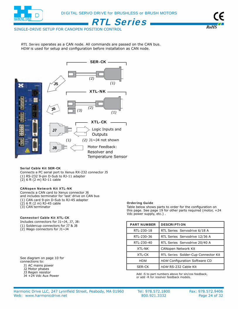
PaRT nuMbeR deScRIPTIon
rTL-230-18 rTL Series Servodrive 6/18 A
rTL-230-36 rTL Series Servodrive 12/36 A
rTL-230-40 rTL Series Servodrive 20/40 A
XTL-nk CAnopen network kit
XTL-Ck RTL Series Solder-Cup Connector kit
HDM HDM Configuration Software CD
Ser-Ck HDM rS-232 Cable kit
J6
SinGLe-DriVe SeTuP For CAnoPen PoSiTion ConTroL
See diagram on page 10 for connections to:
J1 AC mains power J2 Motor phases J3 regen resistor J4 +24 Vdc Aux Power
canopen network Kit XTL-nKConnects a CAn card to Xenus connector J6 and includes terminator for ‘last’ drive on CAn bus(1) CAn card 9-pin D-Sub to rJ-45 adapter (2) 6 ft (2 m) rJ-45 cable (3) CAn terminator
Logic inputs andoutputs
Motor Feedback:resolver andTemperature Sensor
RTL Series operates as a CAn node. All commands are passed on the CAn bus.HDM is used for setup and configuration before installation as CAn node.
Serial cable Kit SeR-cKConnects a PC serial port to Xenus rX-232 connector J5(1) rS-232 9-pin D-Sub to rJ-11 adapter (2) 6 ft (2 m) rJ-11 cable
ordering GuideTable below shows parts to order for the configuration on this page. See page 19 for other parts required (motor, +24 Vdc power supply, etc.) .
connector/cable Kit XTL-cKincludes connectors for J1~J4, J7, J8:(1) Soldercup connectors for J7 & J8 (2) Wago connectors for J1~J4
(2) J1~J4 not shown
XTL-nK
XTL-cK
SeR-cK
(1)(2)
(1)(2)
(3)
J8
J7
J5
(1)
Add -S to part numbers above for sin/cos feedback, or add -r for resolver feedback models.
RoHS
DIGITAL SERVO DRIVE for BRUSHLESS or BRUSH MOTORS
Harmonic Drive LLC, 247 Lynnfield Street, Peabody, MA 01960 Tel: 978.572.1800 Fax: 978.572.9406Web: www.harmonicdrive.net 800.921.3332 Page 25 of 32
RTL Series
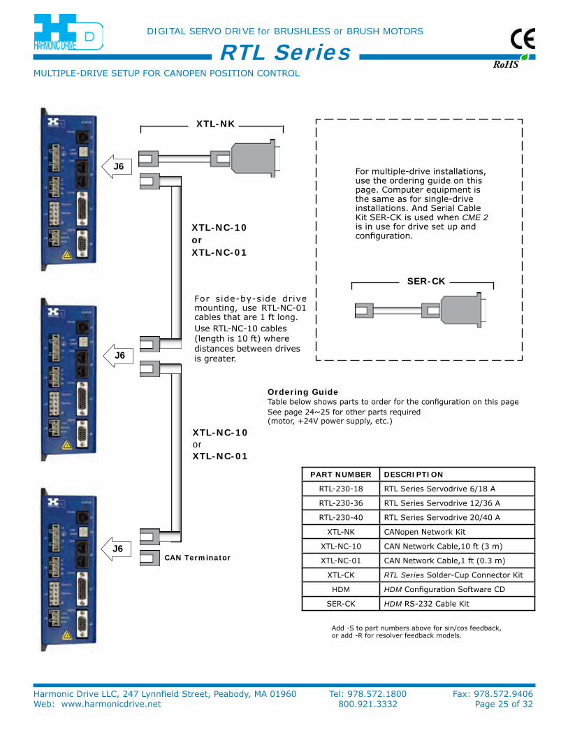
PaRT nuMbeR deScRIPTIon
rTL-230-18 rTL Series Servodrive 6/18 A
rTL-230-36 rTL Series Servodrive 12/36 A
rTL-230-40 rTL Series Servodrive 20/40 A
XTL-nk CAnopen network kit
XTL-nC-10 CAn network Cable,10 ft (3 m)
XTL-nC-01 CAn network Cable,1 ft (0.3 m)
XTL-Ck RTL Series Solder-Cup Connector kit
HDM HDM Configuration Software CD
Ser-Ck HDM rS-232 Cable kit
J6
J6
J6
For multiple-drive installations, use the ordering guide on this page. Computer equipment is the same as for single-drive installations. And Serial Cable kit Ser-Ck is used when CME 2 is in use for drive set up and configuration.
ordering GuideTable below shows parts to order for the configuration on this pageSee page 24~25 for other parts required (motor, +24V power supply, etc.)
For side-by-side drive mounting, use rTL-nC-01 cables that are 1 ft long.use rTL-nC-10 cables (length is 10 ft) where distances between drives is greater.
MuLTiPLe-DriVe SeTuP For CAnoPen PoSiTion ConTroL
XTL-nc-10orXTL-nc-01
XTL-nK
can Terminator
XTL-nc-10orXTL-nc-01
SeR-cK
Add -S to part numbers above for sin/cos feedback, or add -r for resolver feedback models.
RoHS
DIGITAL SERVO DRIVE for BRUSHLESS or BRUSH MOTORS
Harmonic Drive LLC, 247 Lynnfield Street, Peabody, MA 01960 Tel: 978.572.1800 Fax: 978.572.9406Web: www.harmonicdrive.net 800.921.3332 Page 26 of 32
RTL Series
PaRT nuMbeR deScRIPTIon
rTL-230-18 rTL Series Servodrive 6/18 A
rTL-230-36 rTL Series Servodrive 12/36 A
rTL-230-40 rTL Series Servodrive 20/40 A
XTL-Ck RTL Series Solder-Cup Connector kit
HDM HDM Configuration Software CD
Ser-Ck HDM rS-232 Cable kit
J5
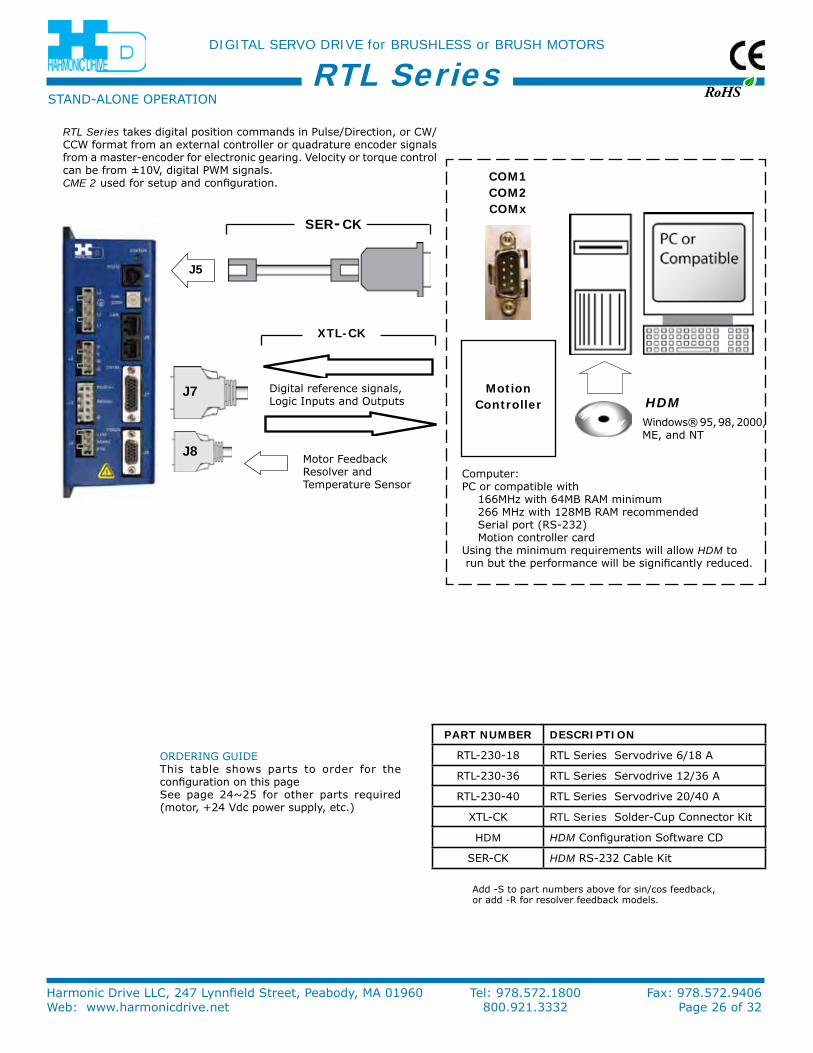
STAnD-ALone oPerATion
Computer:PC or compatible with 166MHz with 64MB rAM minimum 266 MHz with 128MB rAM recommended Serial port (rS-232) Motion controller cardusing the minimum requirements will allow HDM to run but the performance will be significantly reduced.
RTL Series takes digital position commands in Pulse/Direction, or CW/CCW format from an external controller or quadrature encoder signals from a master-encoder for electronic gearing. Velocity or torque control can be from ±10V, digital PWM signals.CME 2 used for setup and configuration.
Digital reference signals, Logic inputs and outputs
Motor Feedbackresolver andTemperature Sensor
orDerinG GuiDeThis table shows parts to order for the configuration on this pageSee page 24~25 for other parts required (motor, +24 Vdc power supply, etc.)
coM1coM2coMx
HDMWindows® 95, 98, 2000, Me, and nT
SeR-cK
XTL-cK
J8
J7 Motioncontroller
Add -S to part numbers above for sin/cos feedback, or add -r for resolver feedback models.
RoHS
DIGITAL SERVO DRIVE for BRUSHLESS or BRUSH MOTORS
Harmonic Drive LLC, 247 Lynnfield Street, Peabody, MA 01960 Tel: 978.572.1800 Fax: 978.572.9406Web: www.harmonicdrive.net 800.921.3332 Page 27 of 32
RTL Series
Edge Filter(Optional)
RS-232(DTE)
HDMASCII
Control
CANMaster
CANNode(s)
+24 VdcPowerSupply
Motor
Quad A/BEncoder
-SModels
-RModels
Sin/CosEncoder Resolver
Line Filter
RegenResistor
(Optional)
Controller or
PLC
AC Mains90~264 Vac
47~63 Hz1 or 3 ph.
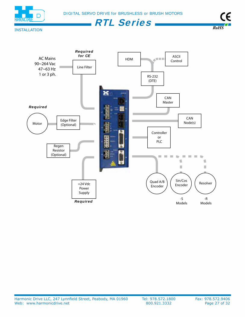
inSTALLATion
Required for CE
Required
Required
RoHS
DIGITAL SERVO DRIVE for BRUSHLESS or BRUSH MOTORS
Harmonic Drive LLC, 247 Lynnfield Street, Peabody, MA 01960 Tel: 978.572.1800 Fax: 978.572.9406Web: www.harmonicdrive.net 800.921.3332 Page 28 of 32
RTL Series
Heatsink
#6-32 Mounting Screws
Dry Film interface Pad
RTL Series Drive
Blue Protective Sheet (Discard)
Clear Protective Sheet (Discard)
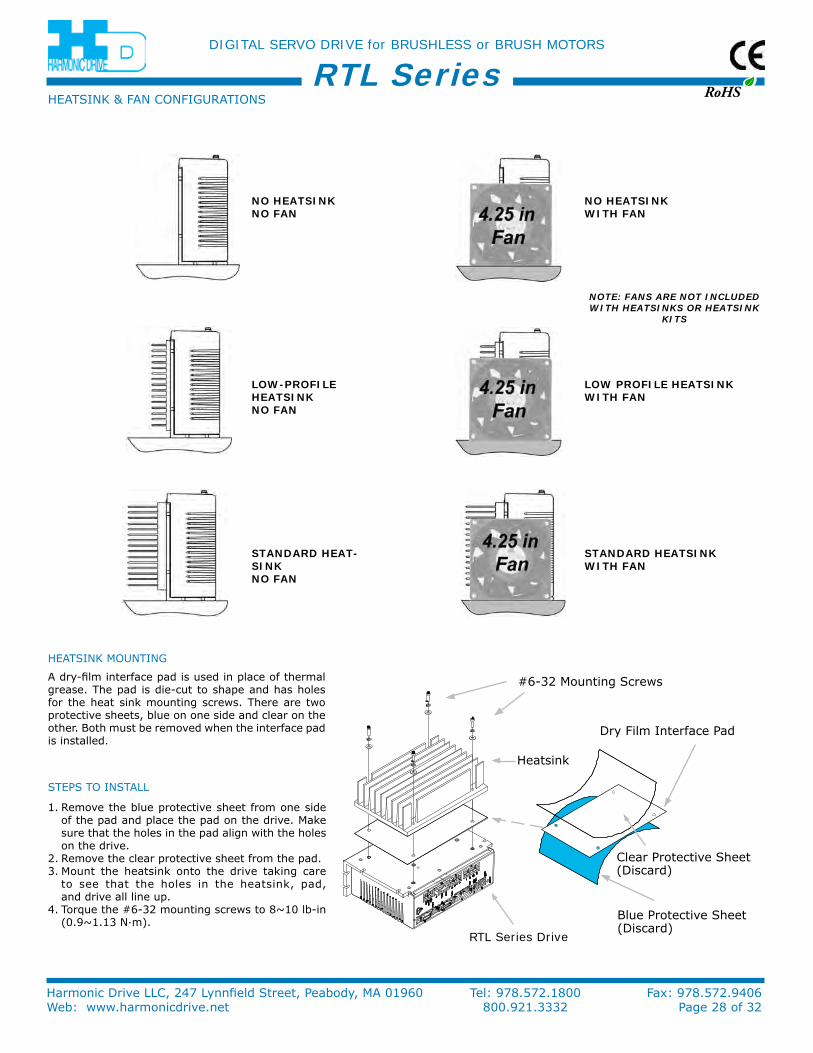
HeATSink & FAn ConFiGurATionS
HeATSink MounTinG
A dry-film interface pad is used in place of thermal grease. The pad is die-cut to shape and has holes for the heat sink mounting screws. There are two protective sheets, blue on one side and clear on the other. Both must be removed when the interface pad is installed.
STePS To inSTALL
1. remove the blue protective sheet from one side of the pad and place the pad on the drive. Make sure that the holes in the pad align with the holes on the drive.
2. remove the clear protective sheet from the pad.3. Mount the heatsink onto the drive taking care
to see that the holes in the heatsink, pad, and drive all line up.
4. Torque the #6-32 mounting screws to 8~10 lb-in (0.9~1.13 n·m).
no heaTSInK no fan
no heaTSInK wITh fan
Low-PRofILe heaTSInK no fan
Low PRofILe heaTSInK wITh fan
STandaRd heaT-SInK no fan
STandaRd heaTSInK wITh fan
NotE: fANs ARE Not INCluDED wItH HEAtsINks oR HEAtsINk
kIts
RoHS
DIGITAL SERVO DRIVE for BRUSHLESS or BRUSH MOTORS
Harmonic Drive LLC, 247 Lynnfield Street, Peabody, MA 01960 Tel: 978.572.1800 Fax: 978.572.9406Web: www.harmonicdrive.net 800.921.3332 Page 29 of 32
RTL Series
20
30
40
50
60
654321
Continuous Output Current (Adc)
Am
bie
ntT
emp
erat
ure
(˚C
)
Model: RTL-230-18Mains: 120 Vac
No Heatsink
Low ProfileHeatsink *
1
2
1
2
* All other heatsink and fan combinationsenable operationat 55 ˚C
20
30
40
50
60
121110987654321
No Heatsink
StandardHeatsink
Low ProfileHeatsink w/fan
Low ProfileHeatsink orno Heatsink w/fan
StandardHeatsink w/fan
4
5
1
2
3
Am
bie
nt T
emp
erat
ure
(°C
)
Model: RTL-230-36Mains: 120 Vac
1
3
4
5
2
Continuous Output Current (Adc)
20
30
40
50
60
654321
Continuous Output Current (Adc)
Am
bie
nt T
emp
erat
ure
(°C
)
Model: RTL-230-18Mains: 240 Vac
No Heatsink
Low ProfileHeatsink *
1
2
All other heatsink and fan combinations enable operation at 55 °C
1
2
3 3
20
30
40
50
60
121110987654321
Continuous Output Current (Adc)
Am
bie
ntT
emp
erat
ure
(˚C
)
Model: RTL-230-36Mains: 240 Vac
StandardHeatsink
Low ProfileHeatsink w/fan
Low ProfileHeatsink orno Heatsinkw/fan
StandardHeatsink w/fan
5
5
4
1
1
2
23
3
4
No Heatsink
20
30
40
50
60
2018161412108642
Continuous Output Current (Adc)
Am
bie
ntT
emp
erat
ure
(˚C
)
Model: RTL-230-40Mains: 120 Vac
No Heatsink
StandardHeatsink
Low ProfileHeatsink w/fan
Low ProfileHeatsink orno Heatsinkw/fan
StandardHeatsink w/fan
1
23
4
5
1 2
34
5
20
30
40
50
60
2018161412108642
Continuous Output Current (Adc)
Am
bie
ntT
emp
erat
ure
(˚C
)
Model: RTL-230-40Mains: 240 Vac
No Heatsink
StandardHeatsink
Low ProfileHeatsink w/fan
Low ProfileHeatsink orno Heatsinkw/fan
StandardHeatsink w/fan
1
2
3
4
5
1
2
3
4
5
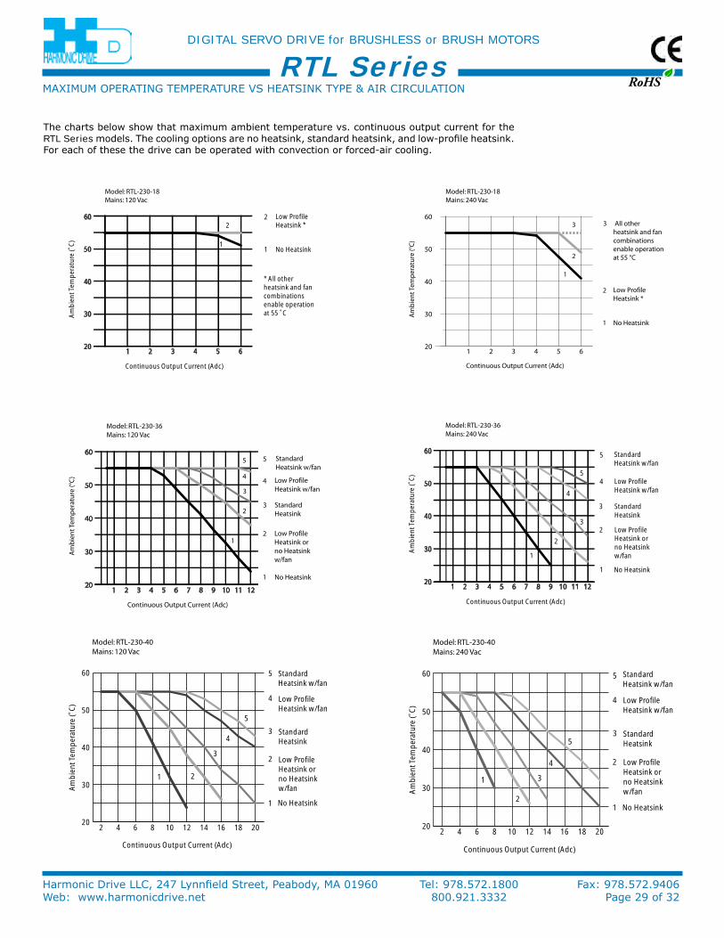
The charts below show that maximum ambient temperature vs. continuous output current for the RTL Series models. The cooling options are no heatsink, standard heatsink, and low-profile heatsink. For each of these the drive can be operated with convection or forced-air cooling.
MAXiMuM oPerATinG TeMPerATure VS HeATSink TyPe & Air CirCuLATion
RoHS
DIGITAL SERVO DRIVE for BRUSHLESS or BRUSH MOTORS
Harmonic Drive LLC, 247 Lynnfield Street, Peabody, MA 01960 Tel: 978.572.1800 Fax: 978.572.9406Web: www.harmonicdrive.net 800.921.3332 Page 30 of 32
RTL Series
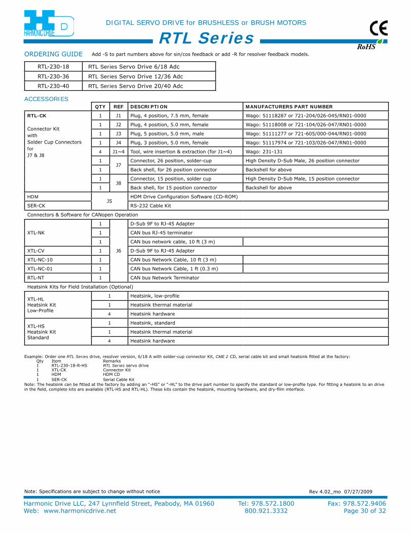
QTy Ref deScRIPTIon ManufacTuReRS PaRT nuMbeR
RTL-cK
Connector kitwithSolder Cup ConnectorsforJ7 & J8
1 J1 Plug, 4 position, 7.5 mm, female Wago: 51118287 or 721-204/026-045/rn01-0000
1 J2 Plug, 4 position, 5.0 mm, female Wago: 51118008 or 721-104/026-047/rn01-0000
1 J3 Plug, 5 position, 5.0 mm, male Wago: 51111277 or 721-605/000-044/rn01-0000
1 J4 Plug, 3 position, 5.0 mm, female Wago: 51117974 or 721-103/026-047/rn01-0000
4 J1~4 Tool, wire insertion & extraction (for J1~4) Wago: 231-131
1J7
Connector, 26 position, solder-cup High Density D-Sub Male, 26 position connector
1 Back shell, for 26 position connector Backshell for above
1J8
Connector, 15 position, solder cup High Density D-Sub Male, 15 position connector
1 Back shell, for 15 position connector Backshell for above
HDMJ5
HDM Drive Configuration Software (CD-roM)
Ser-Ck rS-232 Cable kit
Connectors & Software for CAnopen operation
XTL-nk
1
J6
D-Sub 9F to rJ-45 Adapter
1 CAn bus rJ-45 terminator
1 CAn bus network cable, 10 ft (3 m)
XTL-CV 1 D-Sub 9F to rJ-45 Adapter
XTL-nC-10 1 CAn bus network Cable, 10 ft (3 m)
XTL-nC-01 1 CAn bus network Cable, 1 ft (0.3 m)
rTL-nT 1 CAn bus network Terminator
Heatsink kits for Field installation (optional)
XTL-HL Heatsink kit Low-Profile
1 Heatsink, low-profile
1 Heatsink thermal material
4 Heatsink hardware
XTL-HS Heatsink kit Standard
1 Heatsink, standard
1 Heatsink thermal material
4 Heatsink hardware
Add -S to part numbers above for sin/cos feedback or add -r for resolver feedback models.orDerinG GuiDe
rTL-230-18 RTL Series Servo Drive 6/18 Adc
rTL-230-36 RTL Series Servo Drive 12/36 Adc
rTL-230-40 RTL Series Servo Drive 20/40 Adc
example: order one RTL Series drive, resolver version, 6/18 A with solder-cup connector kit, CME 2 CD, serial cable kit and small heatsink fitted at the factory:Qty item remarks 1 rTL-230-18-r-HS RTL Series servo drive1 XTL-Ck Connector kit 1 HDM HDM CD 1 Ser-Ck Serial Cable kit
note: The heatsink can be fitted at the factory by adding an “-HS” or “-HL” to the drive part number to specify the standard or low-profile type. For fitting a heatsink to an drive in the field, complete kits are available (rTL-HS and rTL-HL). These kits contain the heatsink, mounting hardware, and dry-film interface.
rev 4.02_mo 07/27/2009note: Specifications are subject to change without notice
ACCESSORIES

