digital robust control of throttled … · digital robust control of throttled variable...
TRANSCRIPT

1st FPNI – PhD Symposium, 20.-22. Sept. 2000, Hamburg
DIGITAL ROBUST CONTROL OF THROTTLED VARIABLEDISPLACEMENT HYDRAULIC MOTORS IN AIRCRAFT
POWER DRIVE UNITS
Olaf BIEDERMANNTechnical University Hamburg-HarburgInstitute of Aircraft Systems EngineeringNesspriel 5, D-21129 Hamburg, Germany
Phone: +49 (0)40 428788 210Fax: +49 (0)40 428788 270
Email: [email protected]
The introduction of variable displacement hydraulic motors to secondary and primary flight actuation offers aconsiderable potential for power optimization and saving in aircraft hydraulic systems. The application inaircraft systems requires high safety, reliability and availability at the smallest expense possible. Therefore thecombination of a variable displacement hydraulic motor with a fixed orifice guarantees fail-passive systembehavior. The integration in fly-by-wire flight control architecture leads to digital control structures. Robustcontroller design is forced because of the influence of several uncertain physical parameters during flightmission. Moreover the significant nonlinear characteristic of the throttled VDHM affects dynamic behavior. Anintegral discrete-time robust controller design methodology is presented considering specified requirements asdynamic bandwidth, static position accuracy and stationary power drive performance. Here the parameter spaceapproach is used for direct sampled-data controller synthesis. A static linear state feedback controller is chosen.All combinations of uncertain and linearized parameters leads to a multi-model problem which is solved bysimultaneous stabilization. Finally simulated and experimental results show typical operation cases and verifyexpected system dynamics in time- and frequency-domain.
Keywords: Variable Displacement Hydraulic Motor, Power Drive Unit, Trimmable Horizontal StabilizerActuator, Flight Control Actuation, Robust Control, Sampled-data Control, Parameter Space Design
1 INTRODUCTION
The application of variable displacement hydraulic motors (VDHM) in secondary andprimary flight controls’ power drive units offers a considerable potential for poweroptimization and saving in aircraft hydraulic systems (comp. Ivantysynova, 1998). Thetechnology of VDHM, or so called secondary controlled hydraulic units in the field of mobilehydraulics, enables load adaptive conversion of hydraulic to mechanical power by adjustingdisplacement without typical pressure losses of valve controlled constant displacementmotors. Another advantage is manifested by its flexible electro-hydraulic digital processcontrol.The application in aircraft systems leads to high safety, reliability and at the smallest expensepossible. Therefore the combination of VDHM with a fixed orifice provides certain
2
advantages as inherent passive protection against overspeed and simplification of necessarymonitors (comp. Biedermann and Geerling 2000).Today’s fly-by-wire flight control power drive units have to fulfil a multitude of digitalcontrol functions which finally leads to a full state feedback control structure. This factenables discrete-time state space description and design methods. The influence of severaluncertain physical parameters during flight mission forces a robust controller design.A wide variety of control concepts for variable displacement units has been investigated anddeveloped over the years (e.g. Murrenhoff, 1983, Haas, 1989, Backé and Kögl, 1993,Weishaupt, 1995, Kordak, 1996, Berg, 1999). Besides classical linear design methods(cascade control), robust design approaches have been made. Weishaupt (1995) chooses astate feedback controller design. Robustness should be achieved by parameter identificationand adaptive control. Steady-state speed error is compensated by an extra switch integrator. InBerg (1999) a higher order cascade controller is presented guaranteeing high bandwidthrobust control and position accuracy. Integrator wind-up and high frequency limit-cycles areprevented by an augmentation system. Sampled-data consideration was neglected so far. InKliffken (1997) a robust sampled-data controller synthesis for hydraulic flight controlactuators is presented using the parameter space approach by Ackermann (1993). It enables anintegral, immediate solution of the robust problem for a given static state feedback controller.This paper presents an integral and direct discrete-time robust controller design methodologyconsidering specified design requirements as dynamic bandwidth, static position accuracy andstationary power drive unit performance. The controller is designed for the linear system andis validated by nonlinear simulation and experimental results.
2 SYSTEM CONCEPT
In the first place power drive units of the high lift system, called power control unit (PCU),and of the trimmable horizontal stabilizer, called trimmable horizontal stabilizer actuator(THSA), are suitable applications in aircraft systems. Both applications show similaractuation assembly structures. They are characterized by redundant power drive trainsconverting power by a speed summing gear and via a transmission system to the controlsurface (comp. Figure 1).In Geerling (1997) and Biedermann and Geerling (1998) a new concept for application inPCUs is presented which is expanded in Biedermann and Geerling (2000) by a passive powerlimiting device and power optimized control strategies. This conceptional work has deliveredthe basic approach that is going to be applied in the PCU of the very large transport aircraftAirbus A3XX. The same concept could be applied to THSA considering enhanced primaryflight control actuator specifications as e.g. closed-loop frequency-domain dynamics, staticposition accuracy as well as several stationary performance operation points have to be met.

3
Figure 1: Flight controls’ power drive units
2.1 Electro-Hydraulic Actuation Concept
Figure 1 shows a new possible configuration scheme for a VDHM-driven THSA in four-quadrant operation mode. Displacement of the VDHM is adjusted by swash plate actuator(SPA) which is moved by an electro-hydraulic servovalve (EHSV). Two independentmotor/valve group assemblies drive into a speed summing differential power gear (DG) eachprovided with a pressure-off brake (POB) and brake solenoid valve (BRSV) to ensure safesystem operation after one motor/valve group failure. In case of a single hydraulic systemfailure the stabilizer is operated with half speed. The stabilizer surface itself is moved by afail-safe ball screw/nut assembly. A no-back brake (NB) ensures irreversibility of themechanism. The hydraulic group is separated from the pressure supply by a shut-off valve(SOV) during non-operational time. Passive overspeed protection is reached by combiningVDHM with a turbulent orifice. Thus simple protection against certain failure cases as e.g.hardover of swash plate is guaranteed. While pressure losses due to the orifice seem to becontradictory to the benefits of variable displacement motors, power characteristics andrequirements of flight control actuators justify the use of this concept. During normal,faultless operation pressure losses are acceptable low while in failure mode cases the orificeserves as passive mechanical output power limitation.
Figure 2: Hydro-mechanical scheme of the plant
Flaps
Slats
Trimmable HorizontalStabilizer
Power Control Unit (PCU)
Trimmable Horizontal Stabilizer Actuator (THSA)
VDHM POB
VDHM/Valve Group Assembly 1VDHM/Valve Group Assembly 2
Power Drive Unit
DG
NBSPA
EHSV
SOV BRSV
FS
V ,xM K
pDR
pS
pR
ωM
Mt
i
Qe
4
Each hydraulic motor/valve group assembly is controlled and monitored by an independentdigital electronic unit. Stabilizer position δ control, speed limitation and pressure maintainingfunctionality are feasible by using process signals angular position pick-off ϕ at the outputshaft, motor speed ωM, swash plate position xK and supply pressure pS (comp. Figure 2).
2.2 Characteristic of Throttled VDHM
The combination of VDHM with turbulent orifice leads to a nonlinear plant characteristic.The theoretical torque MM,th of a throttled VDHM is reduced by the pressure loss of the orificewith its coefficient BDR (Biedermann and Geerling 2000):
��� ���� �������
dr
MMvolDR
th
MRS
MDRRS
thM
M
VB
M
VppVpppM .8
1 22
23223, ω
ηπππ−−=−−= (1)
Equation (1) can be separated in the well known theoretical motor torque Mth at constantpressure supply which is weakened by a pressure drop induced loss of torque Mdr. Dynamicbehavior of the motor can be derived from Newton’s equation of momentum
trthMMr MMMJ −−= ,ω� , (2)
whith Mt corresponding with the geared aerodynamic load FS (comp. Figure 2). The frictiontorque Mr consists of Coulomb friction MC, viscous friction Mv and breakout torque MH.Neglecting breakout torque MH and considering equation (1), a describing function for thestationary characteristic with 0=Mω� of a throttled variable displacement motor can befound:
tMCMMMMvolDR
MRS MMdV
BV
pp−⋅−−−
−= )(sign
81
20 23
223 ωωωηππ ω . (3)
In Figure 3 the stationary speed characteristic for graphs of constant load torque Mt are plottedversus theoretical motor torque Mth resp. displacement VM. The typical characteristic ofconventional VDHM is outlined. Here small changes in motor torque Mth resp. displacementVM under constant load Mt lead to significant increase of motor angular speed ωM. As aconsequence speed must usually be limited by the control algorithm (Murrenhoff, 1983 andKordak, 1996). In case of a failure within the control loop, system dynamics will lead tospeeds exceeding permissible range in fractions of a second.In comparison motor speed ωM graphs of a throttled VDHM are bend by the effect of theorifice with increasing motor flow Qe. A speed maximum ωM,max for no load is reached. Theinterpolation of all speed peaks yields an anticline with certain remarkable properties. Alongthis graph a maximum of constant convertible hydraulic power PM,max can be foundcharacterized by constant flow Qe and constant pressure loss pDR = (pS - pR)/3. Furtherincrease of the motor flow produces dramatic turbulent pressure losses and reduces

5
mechanical output power. The combination of a VDHM with an orifice is thus reasonable aslong as the maximum operational power POP,max does not surpass the maximum convertiblepower PM,max. Hence, for practical use a characteristic limitation functionality has to beestablished to guarantee active operation on the favorable side of the anticline (comp. Figure3). This could be realized e.g. by implementing an extra speed limitation function ωlim tostate-of-the-art controllers as already deployed by Murrenhoff (1983), Haas (1989) and Backéand Kögl (1993).
Figure 3: Stationary characteristic and operative range
2.3 Design Requirements
Today’s primary flight control actuation systems have to fulfil a variety of steady-state anddynamic requirements under variable environmental conditions:I) Dynamic frequency response of the position closed-loop controlII) Static accuracy of the position closed-loop controlIII) Stabilizer rate limitation/VDHM speed limitationIV) Stabilizer operational performance: For defined operation points of aerodynamic
loads FS certain surface rates δ� have to be met.V) Pressure maintaining functionality: The reduction of consumed hydraulic power if the
system pressure pS drops under a certain limit to give priority to other flight controlactuation systems of higher priority.
Additionally, throttled VDHM require the following:VI) Characteristic limitation functionality: Implementation of a limitation governing the
nonlinear characteristic of the throttled VDHM.A controller has to be designed which meets all listed requirements under variable anduncertain parameters. Moreover it is the endeavor of the system designer to implement a low-order controller and to avoid limit cycles.
VM / VM,max [-]
active operative range
passive operative range
Active and passive operative characteristicStationary characteristic in motor quadrants
III
III IV
III
III IV
Op,maxP
ωlim
M,maxPM,maxω

6
3 CLOSED-LOOP CONTROL SYSTEM
The favored implementation of the control algorithm is realized in micro controller real-timeenvironment with limited resources in hard- and software. Therefore objectives in choosing asuitable linear control structure lead to static feedback gains and a low-order controller. Theexistence of all measured states enables state feedback controller design. An additional speedlimitation function restricts the operative range of the stationary characteristics which varyunder variable, uncertain parameters. Sampled-data control requires a discrete-time notation.
3.1 State Feedback Control
With a reasonable choice of the sample-time T Ackermann (1985) recommends the analysisof controllability, observability, control, disturbance and tracking error should be performedconsidering the linear continuous-time plant. Basis of the controller design is a linear time-invariant SISO model in well known state space description (Lunze, 1996):
).()(),()()(
ttytdtut
xcebAxx
′=++=�
(4)
Applying equation (4), the plant of the VDHM-driven THSA can be written as
( ) . 0
0, 001, 0
0,
0000
00
, )()(, )()(, )(
1
�
���
�
�
−==′����
���
�
�
=����
���
�
�
−=
==����
���
�
�
=
−+r
K
QySVr
DRxMx
r
DRM
DG
J
AVV
JVV
Jdd
in
t
K
M tMtdtitux
t
ecbA
x
ωω
ωϕ
(5)
As shown in Figure 4 the EHSV is represented by a proportional and the SPA by its integralbehavior. The linearized characteristic (3) and (2) leads to a first order differential equationwith VDRx and dDRω being the linearized coefficients. Parallel two motor operation is expressedwith n = 2, otherwise n = 1. Controllability and observability is not given along the anticlinefor ( ) 0=− DRxMx VV . The full knowledge of all significant, measurable states allows the state
feedback notation (Lunze, 1997):
)()(),()()()(
ttytdtVwt
xcebxkbAx
′=++′−=�
(6)
with controller feedback gain vector k and command signal w(t)
( ) )()(, ttwkkk cx ϕωϕ ==′k . (7)

7
Figure 4: Speed-limited state feedback controller
Compensation of static command position error can be reached by adding a prefilter which iscalculated as (Lunze, 1997)
( ) ϕkV =′−′−= −− 11)( bkbAc . (8)
The prefilter V guarantees exact command response neglecting disturbance. In the presence ofplant disturbance Mt the static position error εϕ=can be derived as follows
tMx
x MVk
k 1
ϕϕε = . (9)
The controller structure is completed by adding a static speed limiting saturation which is wellknown in industrial application (comp. Kordak, 1996). Unfortunately steady-state error εω ofthe speed-limited control loop can be found under disturbance load Mt. Depending ondisplacement VM resp. swash plate actuator position xk the speed limit ωlim can be expressed asa linear function:
���
ω
ω
ε
ωω .0,lim Kx
lim xkk−= (10)
Usually in industrial application this error is compensated by an PI-controller (comp. Kordak,1996). The aim in flight control actuation systems is to avoid integral behavior to minimizecontroller order. Therefore, by using a static speed limiting saturation, the task is to find aspeed and characteristic limitation function ωlim(xK) that satisfies all performance operationpoints. Finally pressure maintaining functionality could be realized by additionally limitingspeed in relation to supply pressure, ωlim = f(xK, pS), but is not discussed here.
V V
A
SV Qy
K
xK � M
Mt
n
iDG �
V V
JMx DRx
r
�
d d
JM DR
r
� ��
kx
k �
k �
V� C
EHSV-SPA VDHM DG
State feedback control with speed limitation PrefilterLimiter
i
� lim,0
8
3.2 THSA Stationary Characteristic and Uncertain Parameters
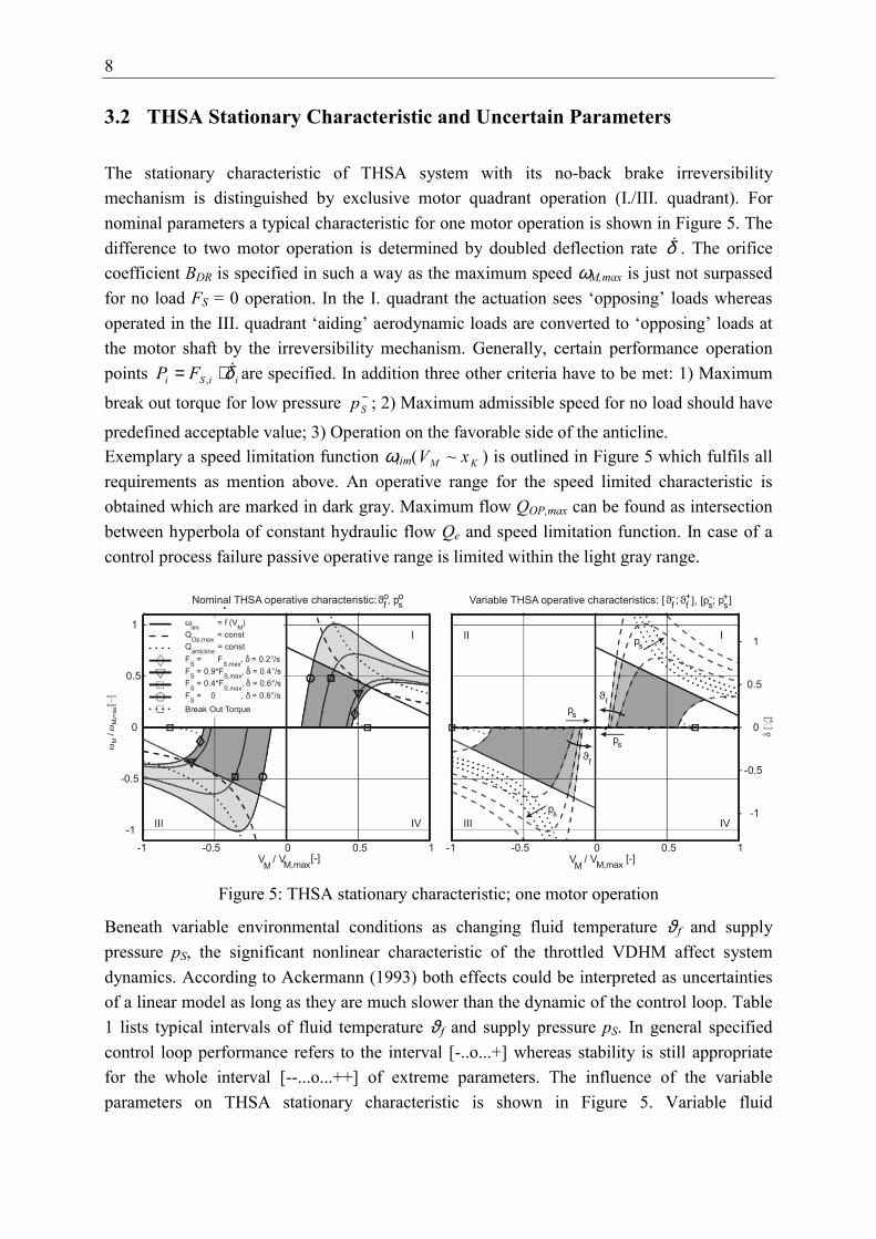
The stationary characteristic of THSA system with its no-back brake irreversibilitymechanism is distinguished by exclusive motor quadrant operation (I./III. quadrant). Fornominal parameters a typical characteristic for one motor operation is shown in Figure 5. Thedifference to two motor operation is determined by doubled deflection rate δ� . The orificecoefficient BDR is specified in such a way as the maximum speed ωM,max is just not surpassedfor no load FS = 0 operation. In the I. quadrant the actuation sees ‘opposing’ loads whereasoperated in the III. quadrant ‘aiding’ aerodynamic loads are converted to ‘opposing’ loads atthe motor shaft by the irreversibility mechanism. Generally, certain performance operationpoints iiSi FP δ�⋅= , are specified. In addition three other criteria have to be met: 1) Maximum
break out torque for low pressure −Sp ; 2) Maximum admissible speed for no load should have
predefined acceptable value; 3) Operation on the favorable side of the anticline.Exemplary a speed limitation function ωlim( KM xV ~ ) is outlined in Figure 5 which fulfils allrequirements as mention above. An operative range for the speed limited characteristic isobtained which are marked in dark gray. Maximum flow QOP,max can be found as intersectionbetween hyperbola of constant hydraulic flow Qe and speed limitation function. In case of acontrol process failure passive operative range is limited within the light gray range.
Figure 5: THSA stationary characteristic; one motor operation
Beneath variable environmental conditions as changing fluid temperature ϑ f and supplypressure pS, the significant nonlinear characteristic of the throttled VDHM affect systemdynamics. According to Ackermann (1993) both effects could be interpreted as uncertaintiesof a linear model as long as they are much slower than the dynamic of the control loop. Table1 lists typical intervals of fluid temperature ϑ f and supply pressure pS. In general specifiedcontrol loop performance refers to the interval [-..o...+] whereas stability is still appropriatefor the whole interval [--...o...++] of extreme parameters. The influence of the variableparameters on THSA stationary characteristic is shown in Figure 5. Variable fluid
-1
-0.5
0
0.5
1
Variable THSA operative characteristics: [ϑ-f ; ϑ
+f ], [p
-s ; p
+s ]
VM
/ VM,max [-]
ps
ps
ϑf
ϑf
III
III IV
-1 -0.5 0 0.5 1
ps
ps
Nominal THSA operative characteristic: ϑof , p
os
I
III IV
-1 -0.5 0 0.5 1 -1
-0.5
0
0.5
1
VM
/ VM,max [-]
ωlim
= f (VM
)Q
Op,max = const
Qanticline
= constF
S = F
S,max, δ = 0.2°/s
FS = 0.9*FS,max, δ = 0.4°/sF
S = 0.4*F
S,max, δ = 0.6°/s
FS = 0 , δ = 0.6°/s
Break Out Torque

9
temperature ϑ f especially affects characteristic gradient, equivalent to viscous frictioncoefficient dMω. Variable pressure pS has a certain effect on the location of the anticline. Bothparameters have no influence on speed limitation function as stated in equation (10).Nonlinear uncertainties are obtained by linearization with VDRx and dDRω being the linearcoefficients in their numerical ranges as quoted in Table 1.
Uncertainty intervalParameter
-- - o + ++ Dependency
pS [bar] 125 170 207 235 235 variable
ϑ f [°C] -55 -15 15 70 110 variable
VQy [m2s-1] 0.097 0.113 0.125 0.133 0.133 variable, f(pS)
VMx [N] 1660 2259 2750 3122 3122 f(pS)
dMω [Nms rad-1] 0.9370 0.0552 0.0171 0.0045 0.0027 f(ϑ f)
VDRx [N] - - 0 1500 - nonlinear
dDRω==[Nms rad-1] - - 0 0.028 - nonlinear
Table 1: Uncertain and variable parameters
3.3 Sampled Data Control
State space description (2) can be easily transferred to a corresponding discrete-time structure(Lunze, 1997):
.,)()(1
kk
kkdkdk
yduTT
xcebxAx
′=++=+ (11)
Continuous-time system and input matrices are transformed by utilizing the matrixexponential
=
=T
d
d
d0
T
e
,e
bb
AA
A
αα (12)
yielding into a sample-time T dependent description of the dynamic system.
10
4 ROBUST DIGITAL CONTROLLER DESIGN
An uncertain plant model of the closed-loop control system with dependencies on sample-time, state feedback gains and variable parameters is defined. The parameter space approachis used to determine the set of stabilizing parameters in a parameter space. This isaccomplished by mapping the boundary of an admissible eigenvalue region via thecharacteristic polynomial into the parameter space. For practical applications, a two-dimensional graphical representation of stability boundaries is easy comprehensible.
4.1 Uncertain Plant Model
The dependency of the closed-loop state space model (6) on the uncertain parameters vector qconsidering discrete-time description (11) is written as (Ackermann, 1993)
( ).
,),(),(),(1
kk
kkdkddk
ydVwTTT
xceqbxkqbqAx
′=++′−=+ (13)
Sampled-data notation leads to a dependency on sample-time T. Vector q combines luncertain interval parameters qi which are described by their upper and lower bounds
+−ii qq and . Usually these parameters span a parameter box Q or so called parameter space
[ ]{ }liqqqQ iii ,...,1 with; =∈= +−q . (14)
Uncertain parameters should be physically motivated to prevent over-estimated conservativebounds. Usually the robust problem is solved for particular combination of Q∈q e.g. thecorners of Q. The uncertain characteristic polynomial of the sampled-data control system is
( )kqbqAIkq ′+−= ),(),(det),,,( TTzTzp ddd . (15)
For a given combination of upper and lower bounds of uncertain plant parameters a four-dimensional problem is obtained depending on the feedback gains and the sample-time.
4.2 Pole Region Assignment
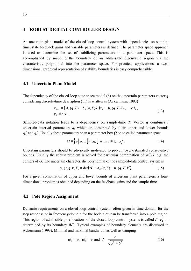
Dynamic requirements on a closed-loop control system, often given in time-domain for thestep response or in frequency-domain for the bode plot, can be transferred into a pole region.This region of admissible pole locations of the closed-loop control systems is called Γ-regiondetermined by its boundary Γ∂ . Typical examples of boundary elements are discussed inAckermann (1993). Minimal and maximal bandwidth as well as damping
22 and ,
baadca bb+
=== +− ωω (16)

11
define a common boundary Γ∂ . As shown in Figure 6 the chosen boundary consists of thespecific elements, a hyperbola and circle in the s-plane. The hyperbola guarantees a certaindegree of damping d and a minimal bandwidth −
bω whereas the circle limits the maximalbandwidth +
bω .With sTz e= the boundary Γ∂ could be transformed into the z-plane. A complex description
)()( αωασ jz += for the boundary Γ∂ in the z-plane is obtained, parameterized by α :
( ) ( )[ ] [ ]
( ) ( ) [ ]�
�
�
∈���� �
�
� −±�
�
� −
−∈−±−==∂
abTjbT
ccTjcTz
IaaT
IT
- ;,1sin1cose
;,sincose)(
22
2222
αα
αααααΓ
ααα
α
(17)
The first part of equation (17) reflects the continuos circle while the second row stands for thehyperbola with αI as the intersection of both graphs. The complex root boundary representsthose combinations of controller parameters which produce conjugate poles on Γ∂ . In case oftwo free controller parameters the complex root boundary Γ∂ can be solved directly for theuncertain characteristic polynomial ),,,( Tzpd kq applying the Boundary RepresentationTheorem (Ackermann, 1993).The intersections of the boundary Γ∂ and the real axis of the z-plane yield real rootboundaries
[ ]acz T −−∈==∂ , ,e)( ααΓ α . (18)
By evaluating the uncertain characteristic polynomial
0),,),(( ≡Tzpd kqα , (19)
solution for single poles on the real root boundaries can be found.
Figure 6: Pole region assignment
-1 -0.5 0
-1
-0.5
0
0.5
1
Re (s) / ωb
Im (s
) / ω
b
s-plane
∂Γ
Γ
Re (z)
Im (z
)
z-plane
Γ
-1 -0.5 0 0.5 1
-1
-0.5
0
0.5
1
d = 0.5
d = 0.7
d = 0.3d = 0.1
a
b
c
d = 0.7
d = 0.1
d = 0.5
d = 0.3
Complex circle
Real boundary
Real boundary
∂Γ
Complex hyperbola

12
4.3 THSA Controller Design
In the case of the VDHM actuation plant three significant concentrated uncertain parametersqi can be defined (l = 3):
.,, 321 ωω DRMDRxMxK
QySV ddqVVqAVV
q −=−== (20)
The desired pole region is specified with
7.0 and 162 , 2 =⋅== +− dbb πωπω . (21)
While today’s applications demand a minimal bandwidth 5.02 ⋅≈− πωb state feedback controloffers a much higher bandwidth range. A maximum bandwidth is chosen keeping a certaindistance to the neglected natural eigenfrequency ωSV of the servovalve. Severalrecommendations (comp. Ackermann, 1985) and engineering design experience lead to amaximum bandwidth 4SVb ωω ≤+ . The step response for d = 0.7 is considered as particularlyfavorable by Ackermann (1985). It shows a minimum overshoot of 4.3% and almost aperiodicbehavior. The magnitude of the frequency response is characterized by the fact that with d >0.7 no resonant peak occurs.Figure 7 displays a graphical representation of the controller region KΓ in two-dimensionalsets of solution. Applying the Boundary Representation Theorem mentioned in section 4.2 thecomplex root boundary Γ∂ (hyperbola and circle) is mapped into the controller-plane. Thereal root boundaries solved in equation (19) appear as straight lines. In addition to commonparameter space approach static control accuracy and steady-state performance specificationcan favorably be implied. Assuming a specified position error εϕ for a given maximum load
+tM and parameter −
MxV equation (9) yields to relation
ϕkkx ⋅≤ 7.5 . (22)
The illustration of the throttled VDHM characteristic in Figure 5 points out essential operationranges leading to admissible upper and lower gradients of the speed limitation function ωlim
(10). A maximum gradient of the speed limitation can be selected:
3.6≤ωk
kx . (23)
Both terms (22) and (23) represent straight lines in the controller plane (comp. Figure 7).Especially static position accuracy imposes further restriction finding an intersection KΓ of anadmissible set of controller parameters ki and sample-time T. For a nominal set of parameters
0q a region 0ΓK can be found that not only Γ-stabilizes the control system, but guarantees
static position accuracy and admissible gradients of the speed limitation function ωlim. A set ofΓ-stabilizers KΓ is thus obtained satisfying simultaneously the whole parameter box Q of allcombination of parameter intervals qi.The four-dimensional problem can be solved by keeping two controller parameter constant.Thus cross-sections of the k-plane are obtained. The variation of the sample-time T and the

13
position feedback gain kϕ show an integral way to find a set of realizable sample-times T withdependency on feedback gains ki fulfilling the robust control problem. The chosen controllervalues are marked with a cross.
Figure 7: Controller plane
5 VERIFICATION AND VALIDATION
The designed controller is verified by a nonlinear simulation and validated by experimentalresults. The test set-up consists of an Airbus A310 differential slat actuation gear driven bytwo industrial axial piston VDHM (Mannesmann-Rexroth Brueninghaus Hydromatik, typeA10VSO). Torque loads at the output shaft of the differential gear are simulated by aservovalve controlled constant displacement motor. The control algorithm is implemented bya Matlab/Simulink based real-time environment executed on a personal computer. Thehardware-in-the-loop simulation allows representation of the dynamic behavior of the THSAmechanical irreversibility mechanism (screw/nut/no-back assembly).
ϕ
ϕ
ϕ
ϕ
ϕ
ϕ
0.5 0.7 0.9 0.3 1.4
2.2
1.8
k [-]ω
k [
-]x
0.5 0.7 0.9 0.3 1.4
2.2
1.8
ϕ
k [-]ω
k [
-]x
0.5 0.7 0.9 0.3
Nominal parameters:
1.4
2.6
2.2
1.8
ϑof , p , k = 0.35, T = 0.01 mso
s ϕ
Speed limitation
Real boundaries
Complex hyperbola
Static accuracy
Complex circle
KΓ
k [-]ω
k [
-]x
0.5 0.7 0.9 0.3
1.4
2.6
2.2
1.8
ϕ
k [-]ω
KΓ
speed lim.
static acc.k
[-]
xϑ
ϑ
ϑ
ϑ
-
+
-
+f
f
f
f
, p
, p
, p
, p
+
+
-
-s
s
s
s
o
+ +
++

14
5.1 Time-Domain ResponseFigure 8 shows a positioning test sequence for nominal parameters and one motor operation.The aim of the sequence is to show transient disturbance step response, steady-state error εωand static position error εϕ=considering the whole nonlinear operative range.At time t = 0.0 sec. (operation point “0”: OP 0) a rate-limited command signal ϕC of 1°stabilizer deflection causes the actuation system to reach steady-state speed saturation at OP1. During system movement a load disturbance step of maximum operation load FS is applied.Hence, the motor speed decreases showing expected aperiodic transient response. At OP 2 themaximum ‘opposing’ load performance is delivered. The commanded position ϕC = 1° isreached with a static position error °≈ 06.0ϕε for operation under maximum load. When loadis relieved (OP 3→OP 4) the remaining position error drops to °≈ 01.0ϕε caused by inherentactuation systems’ Coulomb friction MC and breakout torque MH. A further adaptation of theprefilter V could improve static position accuracy.Starting from OP 4 at time t = 3.5 sec. the whole sequence is repeated by applying a rate-limited command signal ϕC back to 0° stabilizer deflection. It shows system dynamics for‘aiding’ load cases . At OP 6 maximum actuation system performance is reached.Overall command and disturbance transient time response verify expected system dynamics.The comparison between simulation and experiment displays good accordance. Somediscrepancies are apparent during unsteady transient response. The reason can be found in thedynamic tracking error of the experimental load simulation regulator that is not modeled.
Figure 8: Command and disturbance response: Transient time response and state trajectory
5.2 Frequency-Domain Response
For primary flight control actuators usually a frequency-domain specification is given. Figure9 illustrates frequency response for a commanded signal amplitude °= 5.0ˆCϕ and two motoroperation. A comparison between simulation and experiment is made for nominal fluidtemperature 0
fϑ and variable supply pressure pS in its upper and lower bound +−SS pp and . The
0
0.25
0.5
0.75
1
Test sequence: Command position δc, time response δ
0 1 2 3 4 5
-0.5
0
0.5
Motor angular speed ωM
t [sec]
-1
-0.5
0
0.5
1
Test sequence: Power and state plane
VM / VM,max [-]-1 -0.5 0 0.5 1
-1
-0.5
0
0.5
1 ExperimentSimulation
0
-0.5 5
432
86 7
4.5 4.7 4.9 0 0.025 0.050.075
δ c, δ
[°]
ω M / ω M
,max
[-]
2.0 2.2 2.40.925 0.950.975 1
48
3
1
2
7
5
6 ‘Opposing’ load cases:1->2 : no load -> max. op. load3->4: max. op. load -> no load
‘Aiding’ load cases:5->6 : no load -> max. op. load7->8: max. op. load -> no load

15
specified minimum bandwidth Hz1 resp. 2 == −−bb fπω for the linear controller design is
not met because motor speed signal and swash plate servo actuator signal reach saturation for Hz5.0>f . Nevertheless today’s frequency-domain specification of trimmable horizontal
stabilizer actuators are easily met. State feedback control of VDHM enables even higherminimum bandwidth for low-level signal dynamics.
Figure 9: Frequency response
6 CONCLUSION
This paper has presented a direct and integral discrete-time robust controller designmethodology applied for the VDHM-driven THSA. Sets of solutions for the four-dimensionalcontroller have been derived. All specified design requirements as frequency responsedynamics, static position accuracy and steady-state power drive performance are met. Beyondthat even higher minimum bandwidth are realizable. Nonlinear simulations and experimentalresults are in good accordance and verify predicted system dynamics, even though controllerdesign is based on a linearized plant.Overall feasibility of four-quadrant VDHM operation for application in the THSA is proven.The presented technology meanwhile became baseline for the high lift actuation system of theprojected 'megaliner' Airbus A3XX. Similarity in assembly, control and monitor structure canbe found in both flight control actuation systems. Thus the same design approach andmethodology can be used for both applications simplifying engineering effort.Furthermore system control strategies offer further potential improvements. The fullknowledge of all significant states enables improved system monitoring, e.g. ‘online’-failurelocalization and identification as well as in-service life data recording. Moreover improvedmaintainability is possible by enhanced testability and fault diagnosis options. These are idealconditions for more fault tolerant system design which leads to higher system availability.
Phase
-90
-80
-70
-60
-50
-40
-30
-20
-10
0
10
Phas
e sh
ift [d
eg]
0.1 0.2 0.3 0.4 0.5 1 2-9
-8
-7
-6
-5
-4
-3
-2
-1
0
1Frequency response = 0.5°, two motor operation: δ ϑo
f , [p-s; p+
s ]Am
plitu
de ra
tio [d
B]
Frequency [Hz]
Simulation: p ,-s p ,o
s p+s
Experiment: p ,-s p ,o
s p+s
Amplitude
^C

16
7 ACKNOWLEDGEMENTS
The author thanks the Liebherr Aerospace Lindenberg GmbH for promoting and supportingthe research project ‘Positioning of control surfaces with throttled Variable DisplacementHydraulic Motors’ and the DaimlerChrysler Aerospace GmbH for providing typical systemdata.
8 LIST OF NOTATIONS
Symbols and Variables
A [-] system matrixAK [m2] median piston areab [-] input vectorBDR [m3s-1Pa-0.5] orifice flow coefficientc [-] output vectord [-] damping coefficientd(t) [-] disturbance signaldDRω [Nms] throttle damping coefficientdMω [Nms rad-1] viscous friction damping coefficiente [-] disturbance vectorFS [N] aerodynamic load forcei [A] servovalve currentiDG [-] differential gear reductionJr [kg m2] reduced inertiak [-] coefficients of feedback gain vectork [-] state feedback gain vectorKΓ [-] controller regionMC [Nm] Coulomb friction torqueMdr [Nm] pressure loss torqueMH [Nm] break out torqueMM,th [Nm] reduced theoretical motor torqueMr [Nm] friction torqueMt [Nm] load torqueMth [Nm] theoretical motor torqueMv [Nm] viscous friction torquepd [-] discrete-time polynomial characteristicpDR [Pa] pressure loss over orificePM [W] theoretical hydro-mechanic powerPOP [W] effective operational power
17
pR [Pa] return pressurepS [Pa] supply pressureq [-] coefficients of uncertainty vectorQ [-] parameter spacex [-] state vectorq [-] vector of uncertain concentrated parametersQe [m3s-1] effective hydraulic motor flows [-] Laplace operatorT [s] sample-timet [s] timeu(t) [-] input signalV [-] prefilterVDRx [N] orifice reduction gainVM [m-3] displacementVMx [N] motor gainVQy [m2s-1] linear flow coefficientVSV [m A-1] servovalve gainw(t) [-] command signalx [-] state vectorxK [m] piston positiony(t) [-] output signalz [-] discrete-time operatorϑ f [°C] hydraulic fluid temperature∂Γ [-] stability boundaryΓ [-] stability regionα [-] parametric variableαI [-] intersection of hyperbola and circleδ [deg] horizontal stabilizer deflectionεϕ [rad] static position errorεω [rad s-1] steady-state speed errorηvol [-] volumetric efficiencyϕ [rad] angular position at output shaftσ [-] complex root termω [-] real root termωb [rad s-1] bandwidthωlim [rad s-1] speed limitation functionωlim,0 [rad s-1] static speed limitωM [rad s-1] motor angular speedωSV [rad s-1] eigenfrequency of servovalve
18
Indices+ upper boundc commandd discrete-timei counter variablek counter variable- lower boundmax maximalo nominal
Abbreviations
BRSV Pressure-Off Brake Solenoid ValveDG Differential GearEHSV Electro-Hydraulic ServovalveNB No-Back BrakePCU Power Control UnitPOB Pressure-Off BrakeSISO Single Input Single OutputSOV Shut-Off ValveSPA Swash Plate ActuatorTHSA Trimmable Horizontal Stabilizer ActuatorVDHM Variable Displacement Hydraulic Motor
9 REFERENCES
Ackermann, J. (1985). Sampled-Data Control Systems - Analysis and Synthesis, RobustSystem Design. Springer, London.
Ackermann, J. et al. (1993). Robust Control Systems with Uncertain Physical Parameters.Springer, London.
Backé, W., Kögl, Ch. (1993). Secondary controlled motors in speed and torque control.Proceedings of the 2nd JHPS International Symposium on Fluid Power. pp. 241-248.Tokyo, Japan.
Berg, H. (1999). Robuste Regelung verstellbarer Hydromotoren am Konstantdrucknetz. PhDthesis, Gerhard-Mercator University of Duisburg, VDI, Düsseldorf, Germany.
19
Biedermann, O., Geerling, G. (1998). Power Control Units with Secondary ControlledHydraulic Motors - A New Concept for Application in Aircraft High Lift Systems.Proceedings of the Conference on Recent Advances in Aerospace Hydraulics, pp. 73-77, Toulouse, France.
Biedermann, O., Geerling, G. (2001). Einsatz von gedrosselten Verstellmotoren beiFlugzeug-Landeklappensystemen. No 45, Vol 1, pp. 39-44, Vereinigte Fachverlage,Mainz.
Geerling, G. (1997). Secondary Controlled Variable Displacement Motors in Aircraft PowerDrive Units. Proceedings of the 5th Scandinavian International Conference on FluidPower SICEP '97, Ed. 1 , pp. 167-179, Linköping, Sweden.
Haas, H.-J. (1989). Sekundärgeregelte hydrostatische Antriebe im Drehzahl- undDrehwinkelregelkreis. PhD thesis, RWTH Aachen, Germany.
Ivantysynova, M. (1998). Potential of Secondary Control for Hydraulic Drives Used inModern flight Control Systems. Proceedings of the Conference on Recent Advances inAerospace Hydraulics, pp. 67-72, Toulouse, France.
Kliffken, M. G. (1997). Robust Sampled-Data Control of Hydraulic Flight Control Actuators.Proceedings of the 5th Scandinavian International Conference on Fluid Power, SICEP'97, Linköping, Sweden.
Kordak, R. (1996). Hydrostatische Antriebe mit Sekundärregelung. Der Hydrauliktrainer,Bd. 6, Mannesmann-Rexroth, Lohr am Main, Germany.
Lunze, J. (1996). Regelungstechnik 1. Springer, Berlin.
Lunze, J. (1997). Regelungstechnik 2. Springer, Berlin.
Murrenhoff, H. (1983). Regelung von verstellbaren Verdrängereinheiten am Konstant-Drucknetz. PhD thesis, RWTH Aachen, Germany.
Weishaupt, E. (1995). Adaptive Regelungskonzepte für eine hydraulische Verstelleinheit amNetz mit aufgeprägtem Versorgungsdruck im Drehzahl- und Drehwinkelregelkreis.PhD thesis, RWTH Aachen, Germany.