digital proportional radio control fm - hobbicomanuals.hobbico.com/fut/5nlk-6nlk-manual.pdf · ·...
TRANSCRIPT
FutabaDIGITAL PROPORTIONALRADIO CONTROL FM
D60399
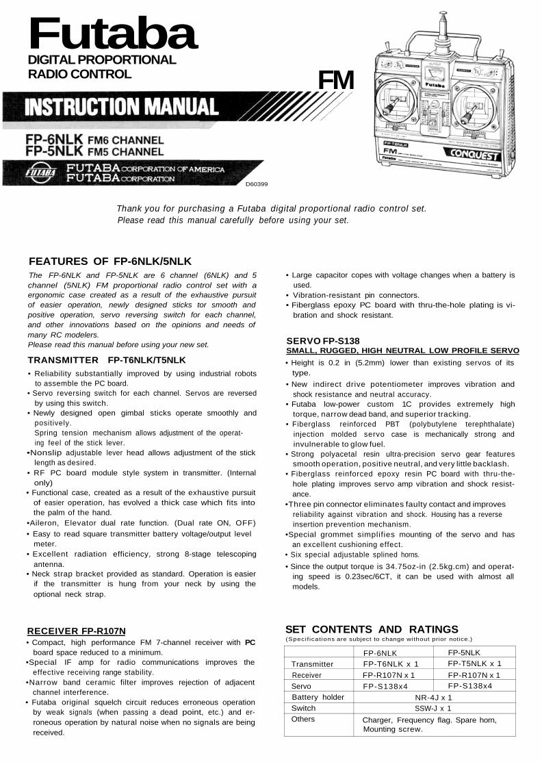
Thank you for purchasing a Futaba digital proportional radio control set.Please read this manual carefully before using your set.
FEATURES OF FP-6NLK/5NLKThe FP-6NLK and FP-5NLK are 6 channel (6NLK) and 5channel (5NLK) FM proportional radio control set with aergonomic case created as a result of the exhaustive pursuitof easier operation, newly designed sticks tor smooth andpositive operation, servo reversing switch for each channel,and other innovations based on the opinions and needs ofmany RC modelers.Please read this manual before using your new set.
TRANSMITTER FP-T6NLK/T5NLK• Reliability substantially improved by using industrial robots
to assemble the PC board.• Servo reversing switch for each channel. Servos are reversed
by using this switch.• Newly designed open gimbal sticks operate smoothly and
positively.Spring tension mechanism allows adjustment of the operat-ing feel of the stick lever.
•Nonslip adjustable lever head allows adjustment of the sticklength as desired.
• RF PC board module style system in transmitter. (Internalonly)
• Functional case, created as a result of the exhaustive pursuitof easier operation, has evolved a thick case which fits intothe palm of the hand.
•Aileron, Elevator dual rate function. (Dual rate ON, OFF)• Easy to read square transmitter battery voltage/output level
meter.• Excellent radiation efficiency, strong 8-stage telescoping
antenna.• Neck strap bracket provided as standard. Operation is easier
if the transmitter is hung from your neck by using theoptional neck strap.
• Large capacitor copes with voltage changes when a battery isused.
• Vibration-resistant pin connectors.• Fiberglass epoxy PC board with thru-the-hole plating is vi-
bration and shock resistant.
SERVO FP-S138SMALL, RUGGED, HIGH NEUTRAL LOW PROFILE SERVO• Height is 0.2 in (5.2mm) lower than existing servos of its
type.• New indirect drive potentiometer improves vibration and
shock resistance and neutral accuracy.• Futaba low-power custom 1C provides extremely high
torque, narrow dead band, and superior tracking.• Fiberglass reinforced PBT (polybutylene terephthalate)
injection molded servo case is mechanically strong andinvulnerable to glow fuel.
• Strong polyacetal resin ultra-precision servo gear featuressmooth operation, positive neutral, and very little backlash.
• Fiberglass reinforced epoxy resin PC board with thru-the-hole plating improves servo amp vibration and shock resist-ance.
•Three pin connector eliminates faulty contact and improvesreliability against vibration and shock. Housing has a reverseinsertion prevention mechanism.
•Special grommet simplifies mounting of the servo and hasan excellent cushioning effect.
• Six special adjustable splined horns.• Since the output torque is 34.75oz-in (2.5kg.cm) and operat-
ing speed is 0.23sec/6CT, it can be used with almost allmodels.
RECEIVER FP-R107N• Compact, high performance FM 7-channel receiver with PC
board space reduced to a minimum.•Special IF amp for radio communications improves the
effective receiving range stability.•Narrow band ceramic filter improves rejection of adjacent
channel interference.• Futaba original squelch circuit reduces erroneous operation
by weak signals (when passing a dead point, etc.) and er-roneous operation by natural noise when no signals are beingreceived.
SET CONTENTS AND RATINGS(Specif icat ions are subject to change without prior notice.)
TransmitterReceiverServoBattery holderSwitchOthers
FP-6NLKFP-T6NLK x 1FP-R107N x 1FP-S138x4
NR-4J x 1SSW-J x 1
Charger, Frequency flag. Spare horn,Mounting screw.
FP-5NLKFP-T5NLK x 1FP-R107N x 1FP-S138x4
TRANSMITTER FP-T6NLK/T5NOperating system : 2 stick, servo reverse
Aileron, Elevator dualswitch,Landing gear switch (5ch)[Switch (6ch) 6NLK only
Transmitting frequency : 53, 72MHz bandsModulation system : FMPower requirement : 9.6V NiCd battery
(NT-8LP)Current drain : 190mA
RECEIVER FP-R107N SERVO FP-S138Receiving frequency : 53, 72MHz bands Control system +pulse width controlIntermediate frequency : 455kHz Operating angle One side 45° or morePower requirement : 4.8V NiCd battery (including trim)
(Common use with servo) Power requirement 4.8V~6VCurrent drain : 13.5mA (4.8V reception) Current drain (IDLE) 6.0V, 8mADimensions : 1.38 x 2.42 x 0.8 in Output torque 34.75oz-in (2.5kg-cm)
(35 .2x61 .7x20 .3mm) Operating speed 0.23 sec/60°Weight : 1.55oz (43g) Dimensions 1.59 x 0.79 x 1.38 inReceiving range : 550 yards (500m) on the (40.5 x 20 x 35.3mm)
ground, 1,100 yards Weight 1.44oz(41g)(1,000m) in the air.(at the best conditions)
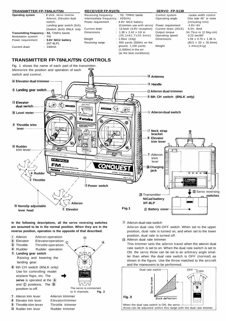
TRANSMITTER FP-T6NLK/T5N CONTROLSFig. 1 shows the name of each part of the transmitter.Memorize the position and operation of eachswitch and control.
Elevator dual trimmer
Landing gear switch
Antenna
Handle
Aileron dual trimmer6th CH switch (6NLK only)
Aileron dual switch
Neck strapbracketElevatortrim lever
Ailerontrimlever
Chargingjack
Power switch
Rudder
Throttle
TransmitterNiCad batteryNT-8LPAileron
ElevatorNonslip adjustablelever head Fig.1 Battery cover
Servo reversingswitches
Ruddertrim lever
Throttle trimlever
Level meter
In the following descriptions, all the servo reversing switchesare assumed to be in the normal position. When they are in thereverse position, operation is the opposite of that described.
®Aileron Aileron operationElevator Elevator operationThrottle Throttle operationRudder Rudder operationLanding gear switchRaising and lowering thelanding gear.
6th CH switch (6NLK only)Use for controlling modelairplane flaps, etc. Theservo is operated at theand positions. The
The servo is connectedto 6 channels. Fig. 2
position is off.
Aileron trim leverElevator trim leverThrottle trim leverRudder trim lever
Aileron trimmerElevator trimmerThrottle trimmerRudder trimmer
Aileron dual rate switchAileron dual rate ON-OFF switch. When set to the upperposition, dual rate is turned on, and when set to the lowerposition, dual rate is turned off.Aileron dual rate trimmerThis trimmer sets the aileron travel when the aileron dualrate switch is set to on. When the dual rate switch is set toON, the servo throw can be set to an arbitrary angle smal-ler than when the dual rate switch is OFF (normal) asshown in the figure. Use the throw matched to the aircraftand the maneuvers to be performed.
throw can be adjusted within this range with the dual rate trimmer.When the dual rate switch is ON, the servo
Fig. 3
OFF 100%Dual rate switch
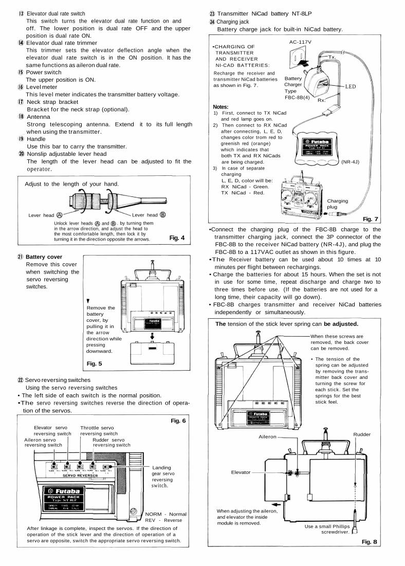
Elevator dual rate switchThis switch turns the elevator dual rate function on andoff. The lower position is dual rate OFF and the upperposition is dual rate ON.Elevator dual rate trimmerThis trimmer sets the elevator deflection angle when theelevator dual rate switch is in the ON position. It has thesame functions as aileron dual rate.Power switchThe upper position is ON.Level meterThis level meter indicates the transmitter battery voltage.Neck strap bracketBracket for the neck strap (optional).AntennaStrong telescoping antenna. Extend it to its full lengthwhen using the transmitter.HandleUse this bar to carry the transmitter.Nonslip adjustable lever headThe length of the lever head can be adjusted to fit theoperator.
Adjust to the length of your hand.
in the arrow direction, and adjust the head tothe most comfortable length, then lock it byturning it in the direction opposite the arrows.
Battery coverRemove this coverwhen switching theservo reversingswitches.
andUnlock lever heads . by turning them
Lever headLever head
Remove thebatterycover, bypulling it inthe arrowdirection whilepressingdownward.
Fig. 5
Servo reversing switches
Fig. 4
Using the servo reversing switches• The left side of each switch is the normal position.•The servo reversing switches reverse the direction of opera-
tion of the servos.
Fig. 6Elevator servoreversing switch
Aileron servoreversing switch
Throttle servoreversing switch
Rudder servoreversing switch
Landinggear servoreversingswitch.
NORM - NormalREV - Reverse
After linkage is complete, inspect the servos. If the direction ofoperation of the stick lever and the direction of operation of aservo are opposite, switch the appropriate servo reversing switch.
Transmitter NiCad battery NT-8LPCharging jackBattery charge jack for built-in NiCad battery.
•CHARGING OFTRANSMITTERAND RECEIVERNI-CAD BATTERIES:
Recharge the receiver andtransmitter NiCad batteriesas shown in Fig. 7.
AC-117V
BatteryChargerTypeFBC-8B(4) Rx:
Notes:1) First, connect to TX NiCad
and red lamp goes on.2) Then connect to RX NiCad
after connecting, L, E, D,changes color trom red togreenish red (orange)which indicates thatboth TX and RX NiCadsare being charged.
3) In case of separatechargingL, E, D, color will be:RX NiCad - Green.TX NiCad - Red.
•Connect the charging plug of the FBC-8B charge to thetransmitter charging jack, connect the 3P connector of theFBC-8B to the receiver NiCad battery (NR-4J), and plug theFBC-8B to a 117VAC outlet as shown in this figure.
•The Receiver battery can be used about 10 times at 10minutes per flight between rechargings.
• Charge the batteries for about 15 hours. When the set is notin use for some time, repeat discharge and charge two tothree times before use. (If the batteries are not used for along time, their capacity will go down).
• FBC-8B charges transmitter and receiver NiCad batteriesindependently or simultaneously.
The tension of the stick lever spring can be adjusted.
Fig. 8
Tx.
Chargingplug
Fig. 7
(NR-4J)
LED
When adjusting the aileron,and elevator the insidemodule is removed.
Use a small Phillipsscrewdriver.
Elevator
Aileron Rudder
• The tension of thespring can be adjustedby removing the trans-mitter back cover andturning the screw foreach stick. Set thesprings for the beststick feel.
When these screws areremoved, the back covercan be removed.

RECEIVER FP-R107N & SERVO FP-S138
Receiver, servos, switches, and batteryconnections
Extension cord
Receiver crystal
7-channel FM receiver FP-R107N
Antenna wire
Landing gearadapter
SwitchSSW-J Charging plug
NR-4J
Fig. 9
The parts enclosed by thedotted lines must bepurchased separately.
6th CHservo(6NLKonly)
Landing gearservo
Landing gearservo
Rudderservo
Throttleservo
Elevatorservo
Aileronservo
PRECAUTIONS• Connect the receiver, servos, switches, and battery firmly as
shown in Fig. 9. Then extend the transmitter and receiverantennas fully.
• Set the transmitter power switch to ON. Then set the receiv-er power switch to ON. The servos stop near the neutralposition. Operate the transmitter sticks and check that eachservo follows the movement of the stick.
•Connect the pushrod to each servo horn, then check if thedirection of travel of each servo matches the direction ofoperation of its transmitter stick. To reverse the directionof servo travel, switch the servo reversing switch.
• Operate each servo over its full stroke, and check if the push-rod binds or is too loose. Applying unreasonable force to theservo horn will adversely affect the servo and quickly drainthe battery. Always make the travel of each control mecha-nism somewhat larger than the full travel (including trim) ofthe servo horn. Adjust the servo horns so that they movesmoothly even when the trim lever and stick are operatedsimultaneously in the same direction.
• Be alert for noise.This set is noise-resistant, but is not completely immune tonoise. We recommend the use of noiseless parts.
•When installing the switch harness, cut a rectangular holesomewhat larger than the full stroke of the switch and installthe switch so that it moves smoothly from ON to OFF. Thisalso applies to the switch mount when the switch is installedinside the fuselage and is turned on and off from the outsidewith a piece of wire, etc. Install the switch where it will notbe exposed to engine oil, dust, etc.
Fig. 10
Wood screwwith flatwasher
RubberbushingGrommet
Plywood,FRP board,Aluminumsheet
Flat washerRubberbushing
Grommet
(Using plywood, FRP, oraluminum sheet)
SERVO MOUNTING(Using wood screws)
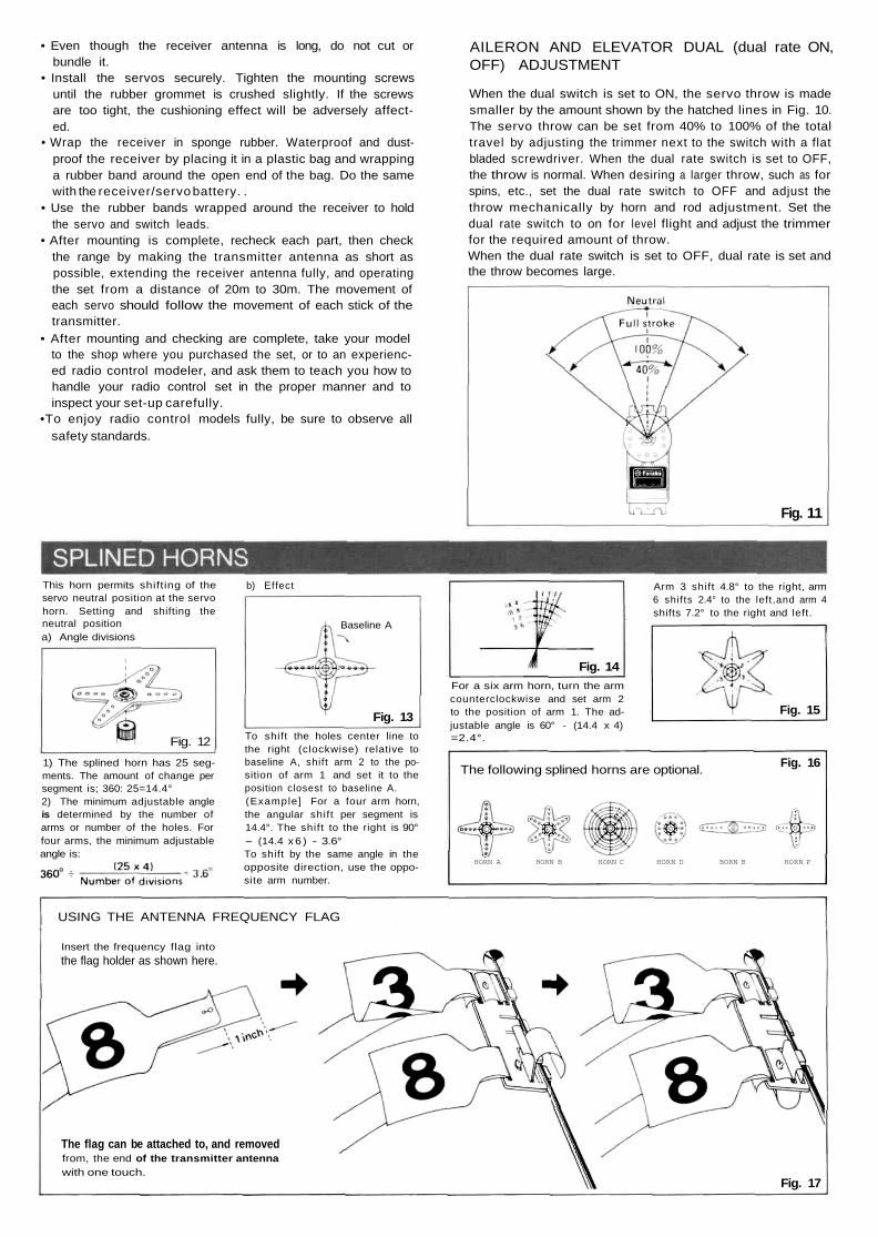
• Even though the receiver antenna is long, do not cut orbundle it.
• Install the servos securely. Tighten the mounting screwsuntil the rubber grommet is crushed slightly. If the screwsare too tight, the cushioning effect will be adversely affect-ed.
• Wrap the receiver in sponge rubber. Waterproof and dust-proof the receiver by placing it in a plastic bag and wrappinga rubber band around the open end of the bag. Do the samewith the receiver/servo battery. .
• Use the rubber bands wrapped around the receiver to holdthe servo and switch leads.
• After mounting is complete, recheck each part, then checkthe range by making the transmitter antenna as short aspossible, extending the receiver antenna fully, and operatingthe set from a distance of 20m to 30m. The movement ofeach servo should follow the movement of each stick of thetransmitter.
• After mounting and checking are complete, take your modelto the shop where you purchased the set, or to an experienc-ed radio control modeler, and ask them to teach you how tohandle your radio control set in the proper manner and toinspect your set-up carefully.
•To enjoy radio control models fully, be sure to observe allsafety standards.
AILERON AND ELEVATOR DUAL (dual rate ON,OFF) ADJUSTMENT
When the dual switch is set to ON, the servo throw is madesmaller by the amount shown by the hatched lines in Fig. 10.The servo throw can be set from 40% to 100% of the totaltravel by adjusting the trimmer next to the switch with a flatbladed screwdriver. When the dual rate switch is set to OFF,the throw is normal. When desiring a larger throw, such as forspins, etc., set the dual rate switch to OFF and adjust thethrow mechanically by horn and rod adjustment. Set thedual rate switch to on for level flight and adjust the trimmerfor the required amount of throw.When the dual rate switch is set to OFF, dual rate is set andthe throw becomes large.
Fig. 11
This horn permits shifting of theservo neutral position at the servohorn. Setting and shifting theneutral positiona) Angle divisions
b) Effect
Fig. 12
Fig. 13
1) The splined horn has 25 seg-ments. The amount of change persegment is; 360: 25=14.4°2) The minimum adjustable angleis determined by the number ofarms or number of the holes. Forfour arms, the minimum adjustableangle is:
To shift the holes center line tothe right (clockwise) relative tobaseline A, shif t arm 2 to the po-sition of arm 1 and set it to theposition closest to baseline A.(Example] For a four arm horn,the angular shift per segment is14.4°. The shift to the right is 90°- (14.4 x 6 ) - 3.6°To shift by the same angle in theopposite direction, use the oppo-site arm number.
Fig. 14
Arm 3 shift 4.8° to the right, arm6 shif ts 2.4° to the left,and arm 4shifts 7.2° to the right and left.
For a six arm horn, turn the armcounterclockwise and set arm 2to the position of arm 1. The ad-justable angle is 60° - (14.4 x 4)=2.4°.
Fig. 15
The following splined horns are optional. Fig. 16
Baseline A
HORN A HORN B HORN C HORN D BORN B HORN P
USING THE ANTENNA FREQUENCY FLAG
Insert the frequency flag intothe flag holder as shown here.
The flag can be attached to, and removedfrom, the end of the transmitter antennawith one touch.
Fig. 17

No.
1
2
3
4
5
6
7
8
9
10
11
12
13
14
15
16
17
18
19
20
21
22
Part Name
Upper case
Middle case
Bottom case
Metal bearing
Potentiometer
VR drive plate
Motor
Motor pinion
VR set screw
1st gear
2nd gear
3rd gear
Final gear
Intermediate shaft
2-stage shaft
Servo horn 0
Horn set screw 2.6x8
Printed wiring board . . . . S138
S138. . . .3PB-WRB300
Lead wire packing
Case set screw
Nameplate . . . . S138
Part No.
S05650
S06010
S06020
S04134
i39995
S02753
S91218
S02461
J55016
S02751
S02491
S02492
S02752
S02495
S02494
S01239
J55178
AS 1305
AT2465
S90045
J50360
S60141
Fig. 18
REPAIRSERVICE
To insure prompt service, please follow the instructions given below.1. Charge the batteries for at least 18 hours prior to shipment.2. Return the system only. Not your complete installation. Remove the servos from their
mounts and remove the foam padding from the receiver.3. Plugs or other modifications which interfere with factory test procedures will be returned to
factory standard at your expense.4. Carefully pack all components individually, using sufficient packing material to prevent
damage during shipment.5. Include a brief but thorough explanation of all problems and service required and tape it to
the back of the transmitter. Place a label describing the function of the servo on each servo.6. Be sure to include your full address and tel. No., zip code inside the box as well as on the
outside.7. Include a packing list of all items being returned, and double check to make sure that all
items are packed.8. Upon receipt of your equipment at the Futaba factory, an estimate of the cost of repair
(over $25.00 only) will be sent to you. Your equipment will then be repaired and returnedto you upon receipt of payment or C.O.D. (cash).
This factory repair service applies only to the continental U.S.A., Hawaii, and Alaska.
Australia: FUTABA SALES AUSTRALIA PTY LTD.,MELBOURNE TEL: 211.4788
Argentine: MODELISMO AERONAUTICO DEGA SRL.BUENOS AIRES TEL: 393-2299
Canada: UDISCO LTD., MONTREALTEL; 481 8109
Chile: HOBBY LANDIA, SANTIAGOTEL: 743957
Denmark: FUTABA IMPORT DENMARK.COPENHAGEN TEL: 0291 0101
England: RIPMAX LIMITED. LONDONTEL: 01 8048272
Finland: NORETRON KY. HELSINKITEL: 90 488880
Greece: C. & G. MACRIYIANNIS CO., PIRAEUSTEL: 021 3604 391 • or 021 4176191
Hong Kong: RADAR CO LTD TEL: 3.680507Italy: RADIOSISTEMI SRL, Carrara
TLX: 500494 FORTIM IFAX: 0039 585 52247
Lebanon: KHAIRALLAH MODELCRAFT. BEIRUTTEL: 326 681
New Zealand: AMALGAMATED WIRELESS(AUSTRALIA) N.Z. LTD. WELLINGTON
=— TEL: 58979Norway: HARALD LYCHE CO A/S. Drammen
TEL: (03) 83 39 70Singapore: SINGAPORE HOBBY SUPPLIES
TEL: 5330337South Africa: REDIPAK (PTY.) LTD.,
JOHANNESBURG TEL: 21 1511Spain: HOBBY & TOY INTERNATIONAL,
VALENCIA TEL: (96) 357 23 93Sweden: RADIO CONTROL CENTER,
JONKOPING TEL: 036 145360U.S.A.: FUTABA CORPORATION OF AMERICA,
CALIFORNIA TEL; 2135379610W.Germany: ROBBE MODELLSPORT GMBH,
GREBENHAIN TEL: 06644 870